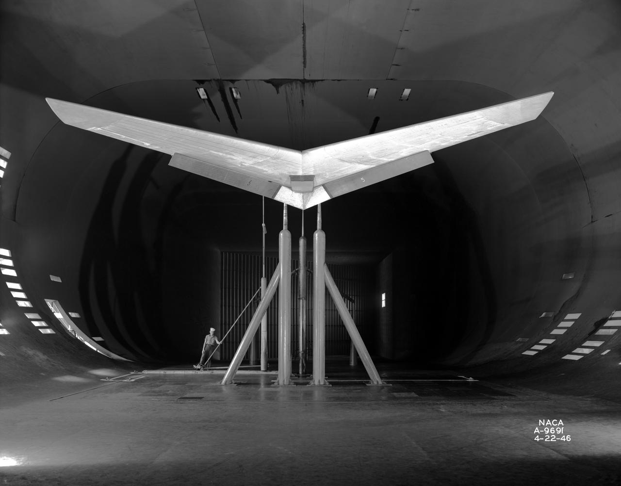
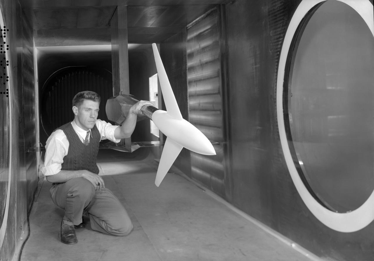
Front View of -45 deg. Forward swept wing with inboard split flaps deflected 60 deg. In NACA Ames 40x80 foot Wind Tunnel.
The F-111B with its wings swept to their maximum angle. It carried the Mission Adaptive Wing, a single-piece composite structure with leading and trailing edges that could be lowered or raised in flight.
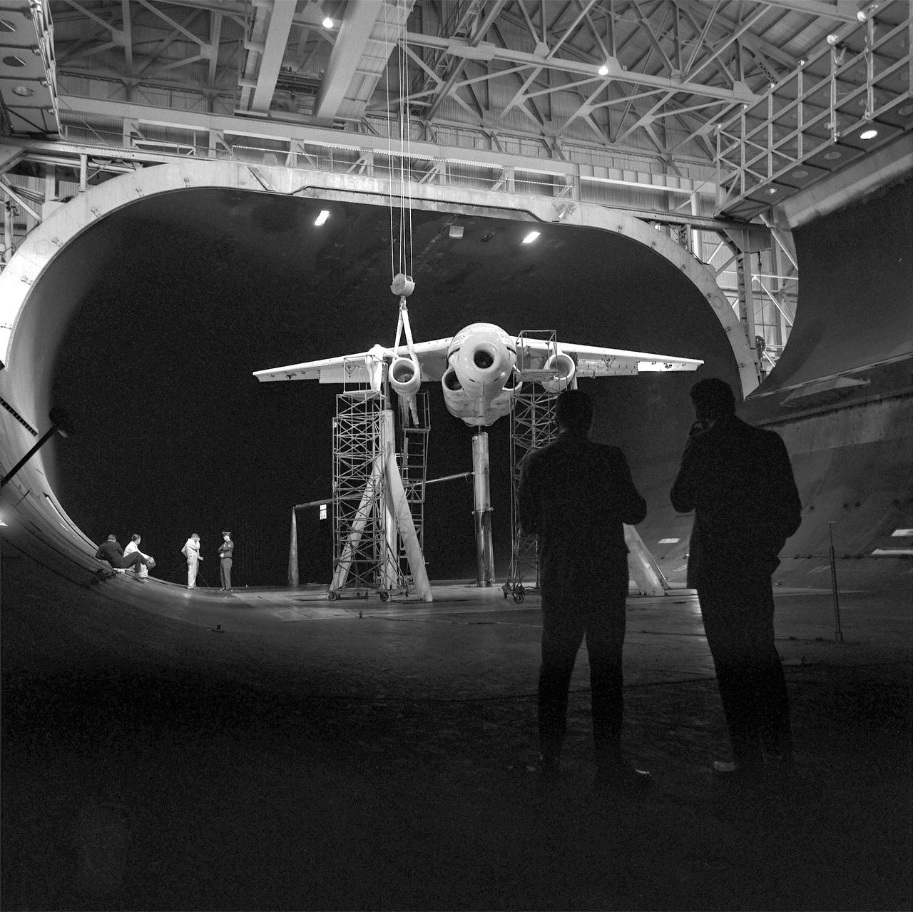
(11/12/1971) 3/4 Scale swept augmentor wing Quest model being installed into the test section of the ames 40 x 80 foot wind tunnel, overhead doors open.
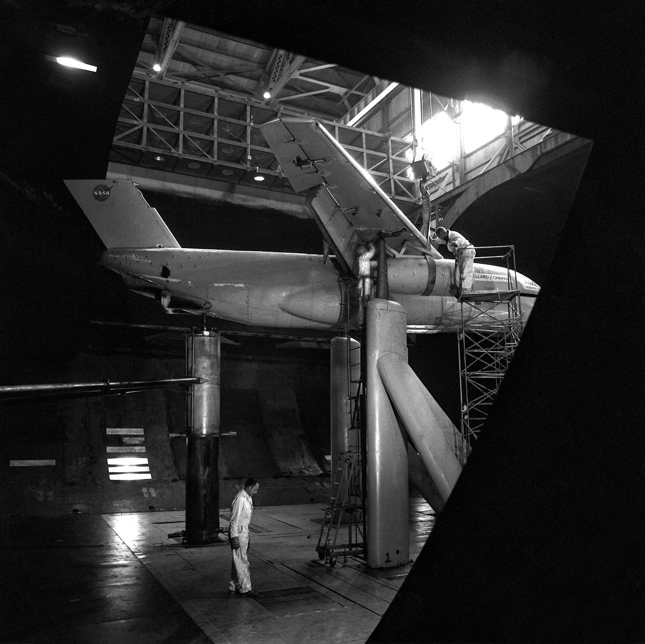
(11/12/1971) 3/4 rear view of swept 75% scale augmentor wing quest model being installed into the test section of the Ames 40x80 foot wind tunnel, overhead doors open.
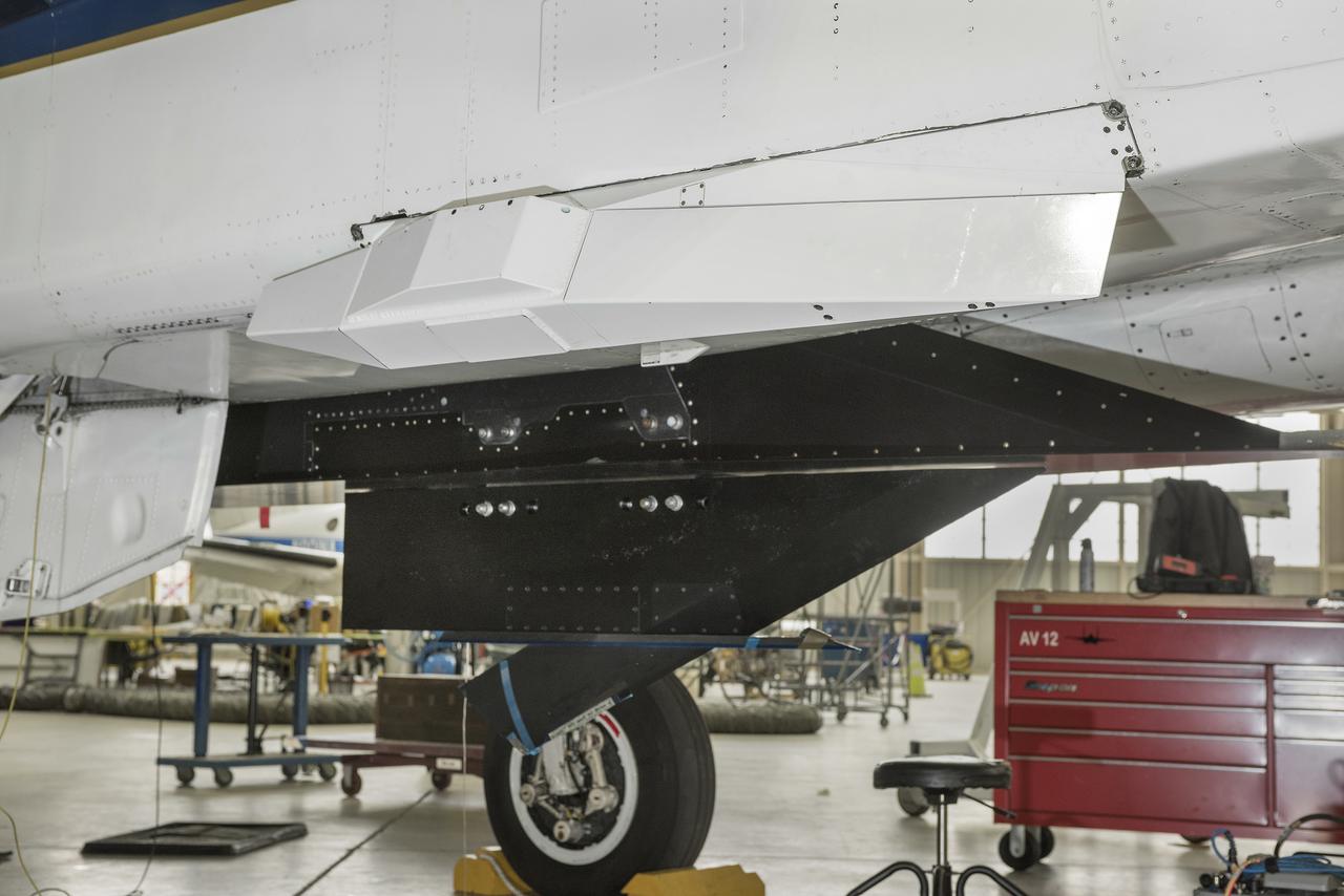
The Swept Wing Laminar Flow test article, integrated to the underside of a NASA F-15, will examine the effectiveness of different configurations of small dots, called distributed roughness elements, to extend smooth, laminar airflow over a wing’s depth, reducing friction drag.
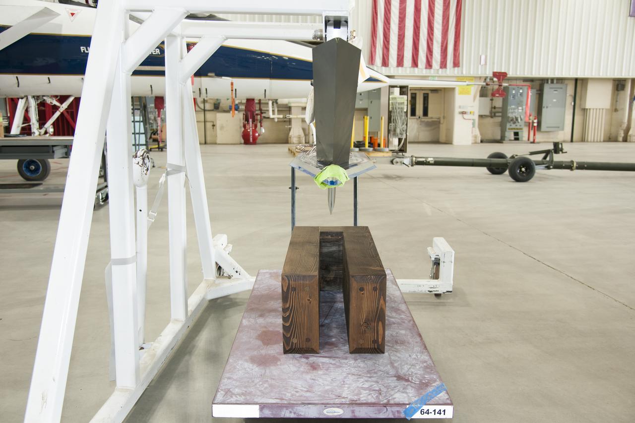
Testing different configurations of distributed roughness elements on the Swept Wing Laminar Flow test article, seen suspended above, will allow NASA researchers to observe which distributions are most efficient in extending laminar flow over a supersonic aircraft’s wing.
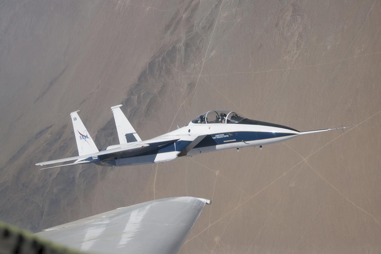
NASA’s F-15 research test bed will expose the Swept Wing Laminar Flow test article to speeds up to Mach 2, matching conditions presented during wind tunnel testing at NASA’s Langley Research Center.
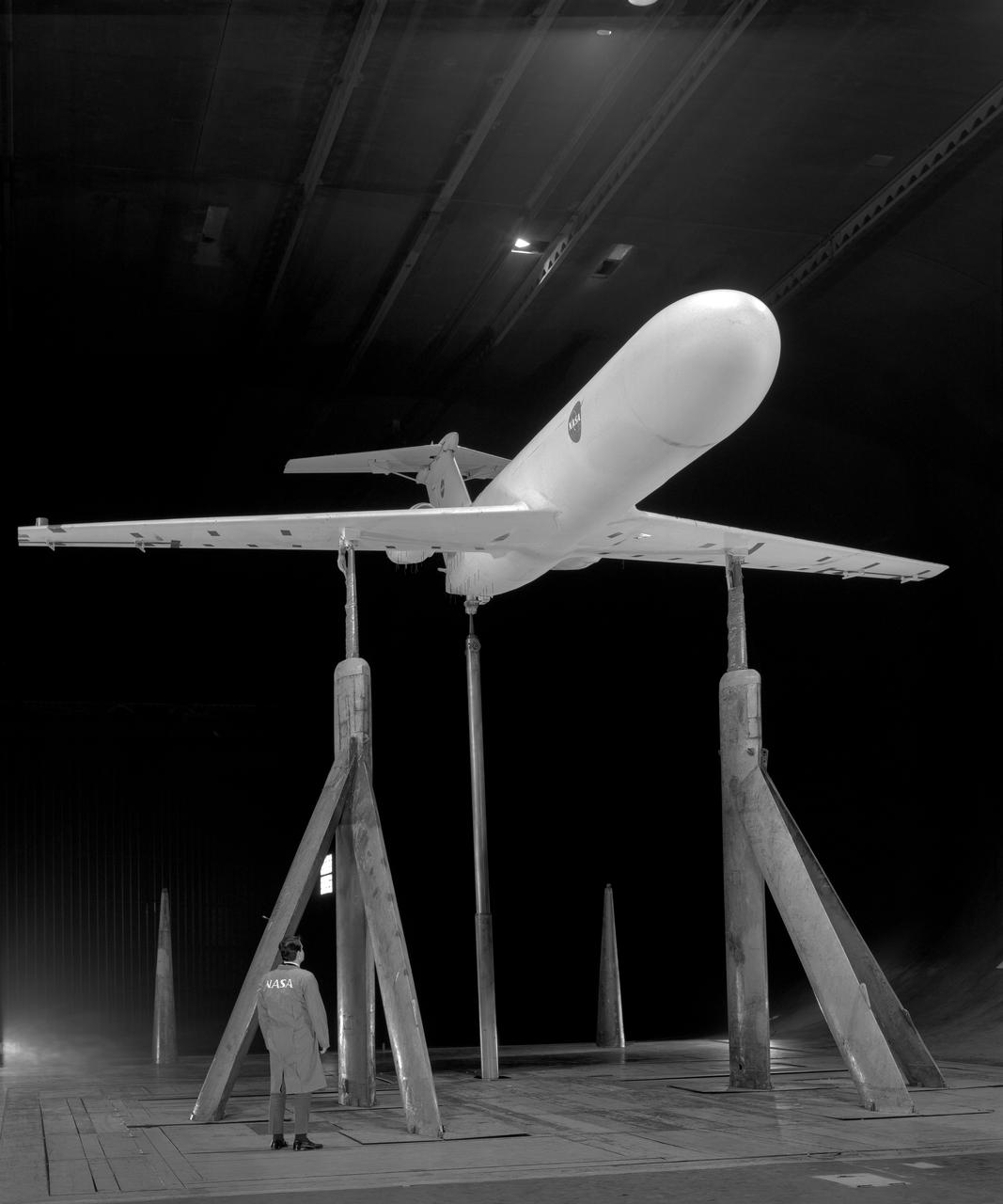
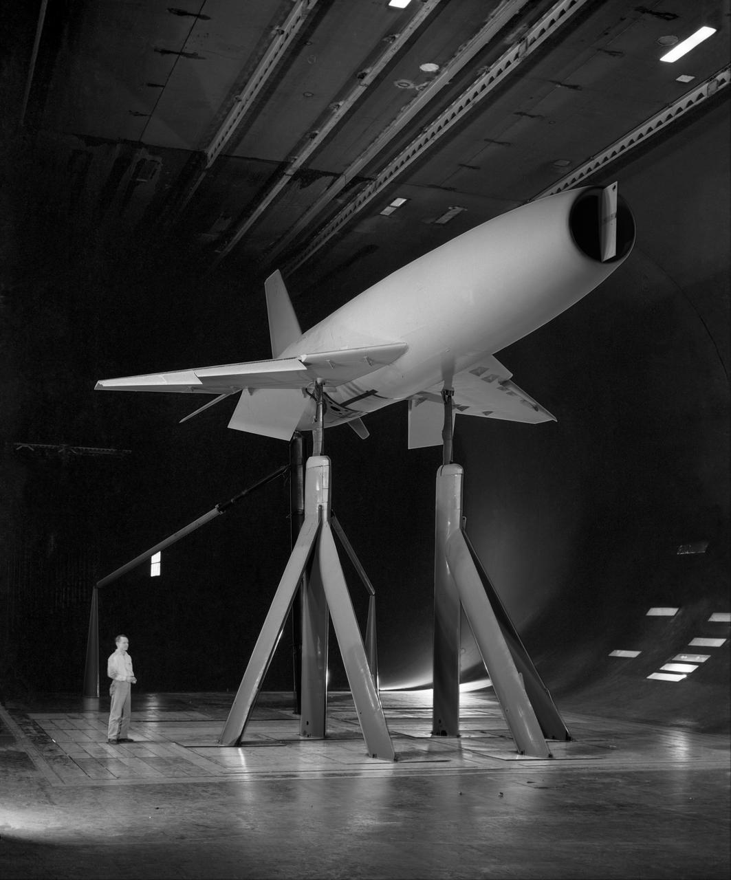
Deep Stall Model in Ames 40x80 foot Wind Tunnel. 3/4 front view from below of swept wing jet transport with T-Tail and Aft Engins, with Art Morris.
6x6 wind tunnel test on the effects of wing sweep.
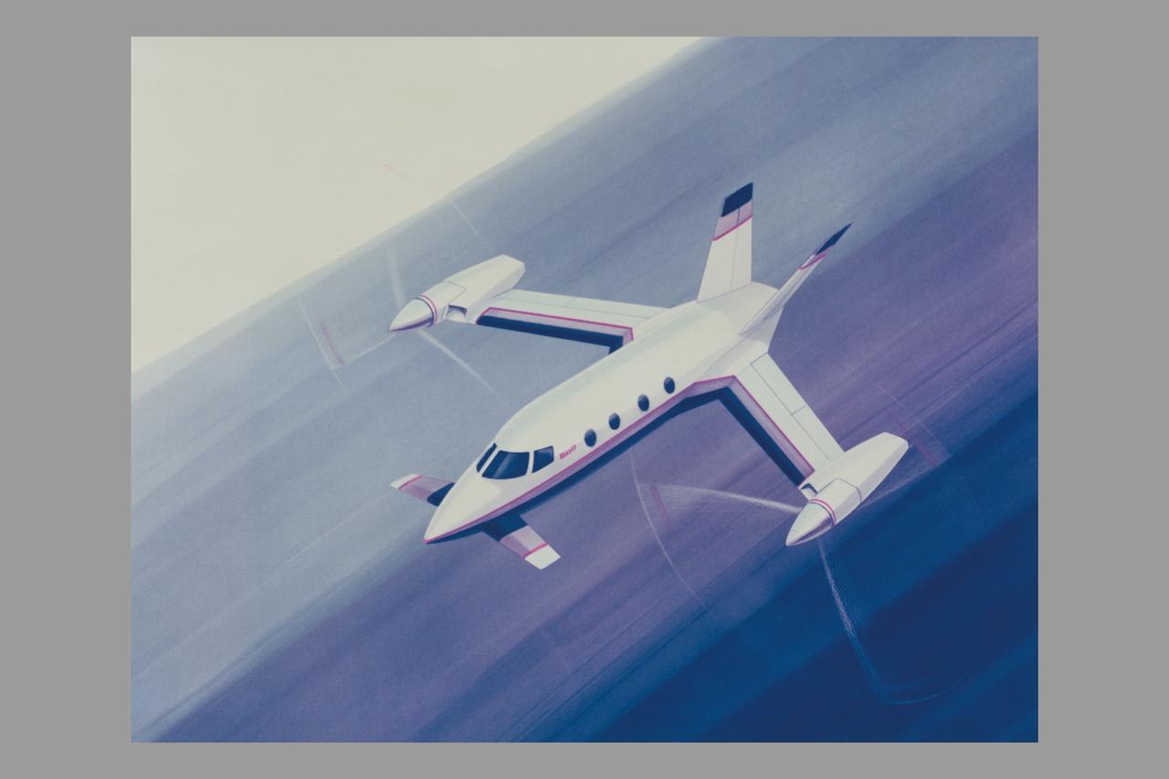
Artwork: Bell Textron Co. Bell Textron Tilt Rotor Forward Swept Wing Configuration (Bell-029564 Swept Wing Tilt Rotor Concept)
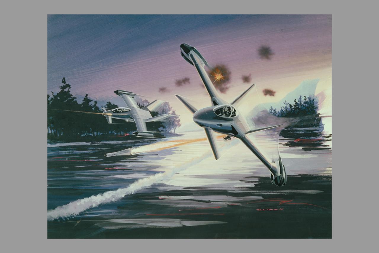
Artwork: Bell Textron Co. Bell Textron Tilt Rotor folding swept wing and Forward Swept Wing Configurations (Bell-030355 Military High Speed Tilt Rotor)
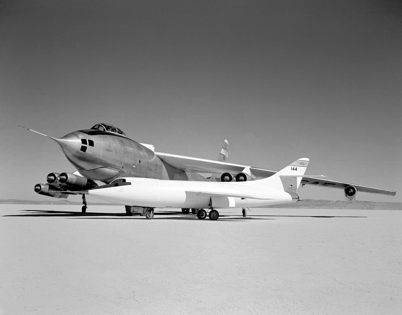
In 1954 this photo of two swept wing airplanes was taken on the ramp of NACA High-Speed Flight Research Station. The Douglas D-558-ll is a research aircraft while the Boeing B-47A Stratojet is a production bomber and very different in size. Both contributed to the studies for swept back wing research.
Application of blowing type boundry-layer control to the leading and trailing edge flaps of a 52 deg swept wing. 3/4 view of Aspect Ratio 2.8, taper ratio .17, 45 deg swept back wing model -3/4 front view

Overhead view of Boeing Super Sonic Transport , wings un-swept.
NATIONAL ADVISORY COMMITTEE FOR AERONAUTICS 0012 NEW SWEPT WING INSTRUMENTED MODEL
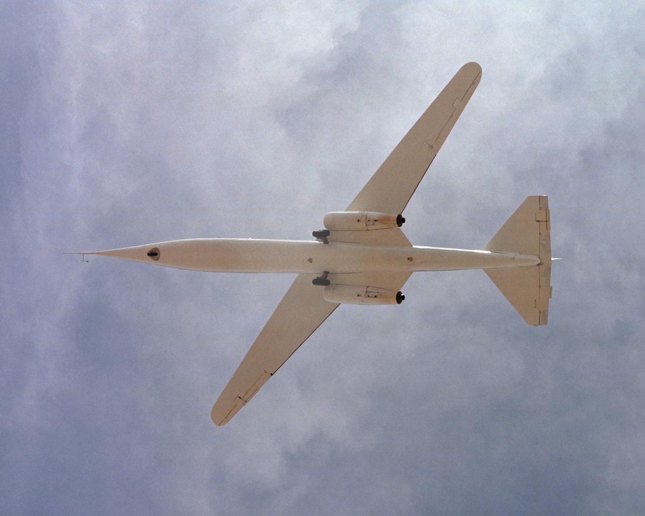
The AD-1 aircraft with its wing swept. Visible are the twin jet engines that powered the aircraft and the fixed landing gear.
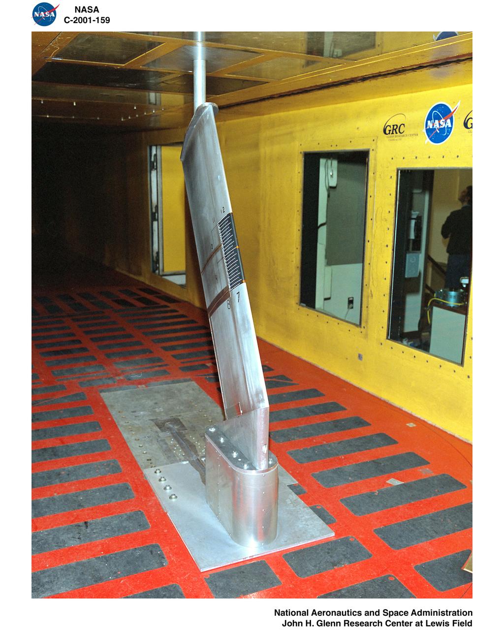
SWEPT WING ICING FUNDAMENTALS MODEL NUMBER 2D GLC305 18 INCH CORD SET AT 28 DEGREE SWEEP ANGLE
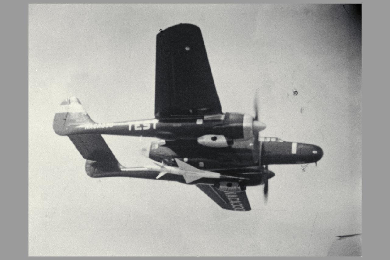
Photo by NACA 45 degree Sweptback wing model drop test Close-up of Body as it Leaves the Plane. Investigation of a Cambered and Twisted 45 degrees Swept-back Wing in the Transonic Range by the Recoverable-body Techniques.
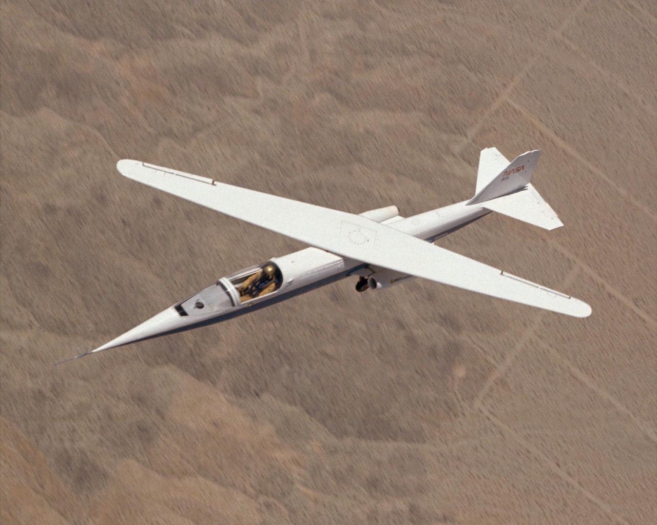
AD-1 in flight. Flight #30. The AD-1 aircraft in flight with its wing swept at 60 degrees, the maximum sweep angle.
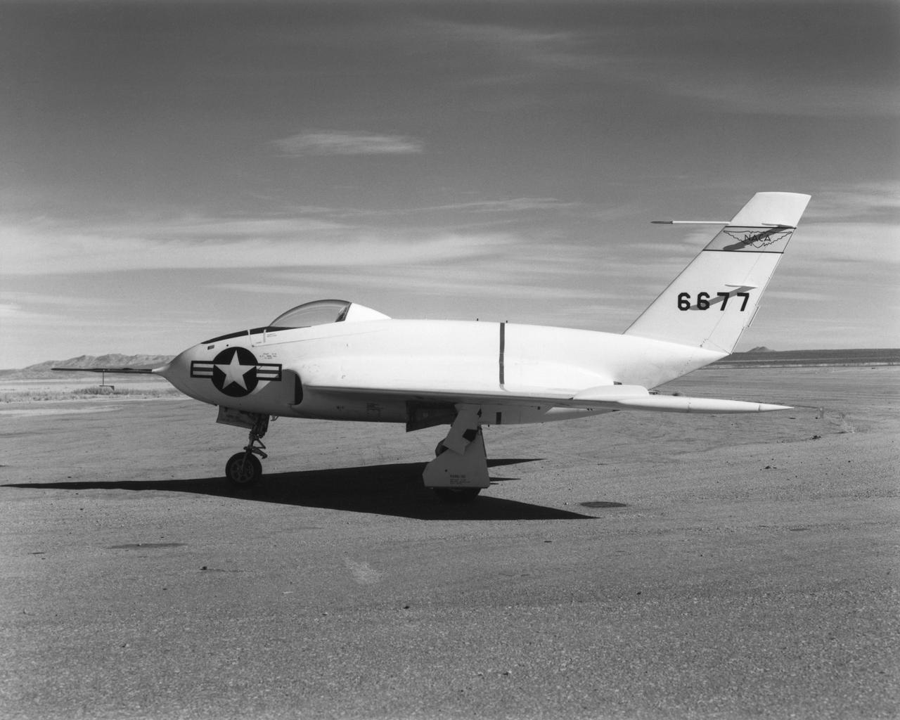
In this 1950 view of the left side of the NACA High-Speed Flight Research Station's X-4 research aircraft, the low swept wing and horizontal taillest design are seen. The X-4 Bantam, a single-place, low swept-wing, semi-tailless aircraft, was designed and built by Northrop Aircraft, Inc. It had no horizontal tail surfaces and its mission was to obtain in-flight data on the stability and control of semi-tailless aircraft at high subsonic speeds.
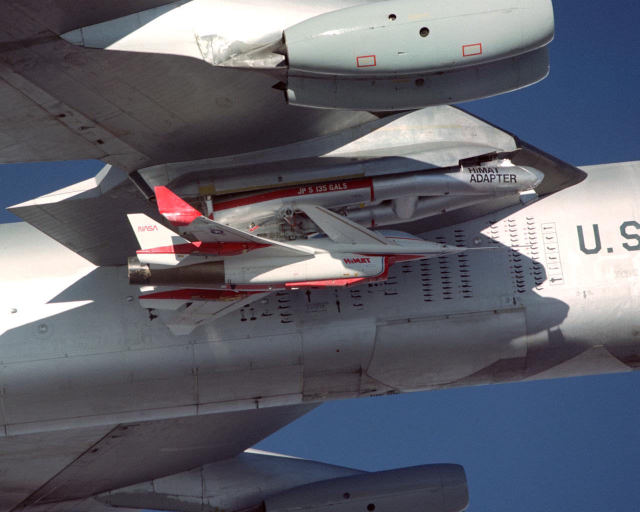
A close-up view of the Highly Maneuverable Aircraft Technology (HiMAT) research vehicle attached to a wing pylon on NASA’s B-52 mothership during a 1980 test flight. The HiMAT used sharply swept-back wings and a canard configuration to test possible technology for advanced fighters.
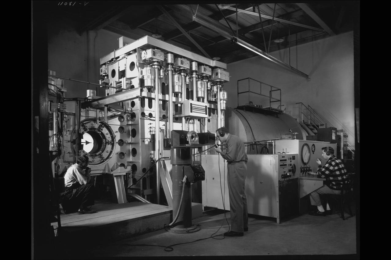
NACA Photographer NASA Ames 1X3Ft W.T Blowdown, flexible throat: A swept wing model readied for a test in June 1948, in the 1 by 3 foot blowdown tunnel with a variable geometry throat mechanism
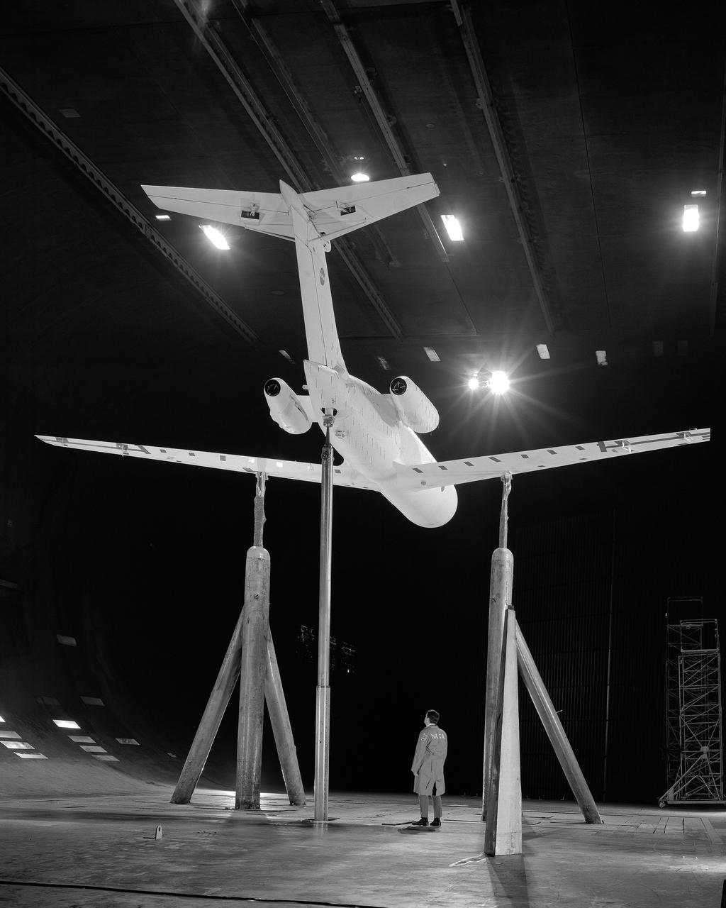
3/4 rear view from below of swept wing jet transport with T-Tail and Aft Engins, with Art Morris. Deep Stall Model in Ames 40x80 foot Wind Tunnel.
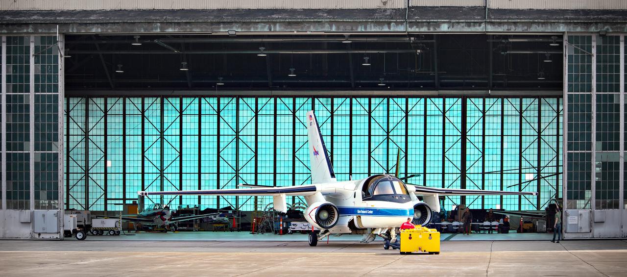
The Lockheed Viking S-3B aircraft is being pulled out of the hangar at Glenn Research Center in preparation for its departure and retirement from service. This former NAVY aircraft was the last such aircraft still flying. It has gone to a museum on the west coast. After leaving service with the NAVY, it came to GRC to be used in aircraft icing experiments. The swept wings made it suitable for such research as opposed to the straight wings on GRG’s other icing research aircraft, the De Havilland Twin Otter.

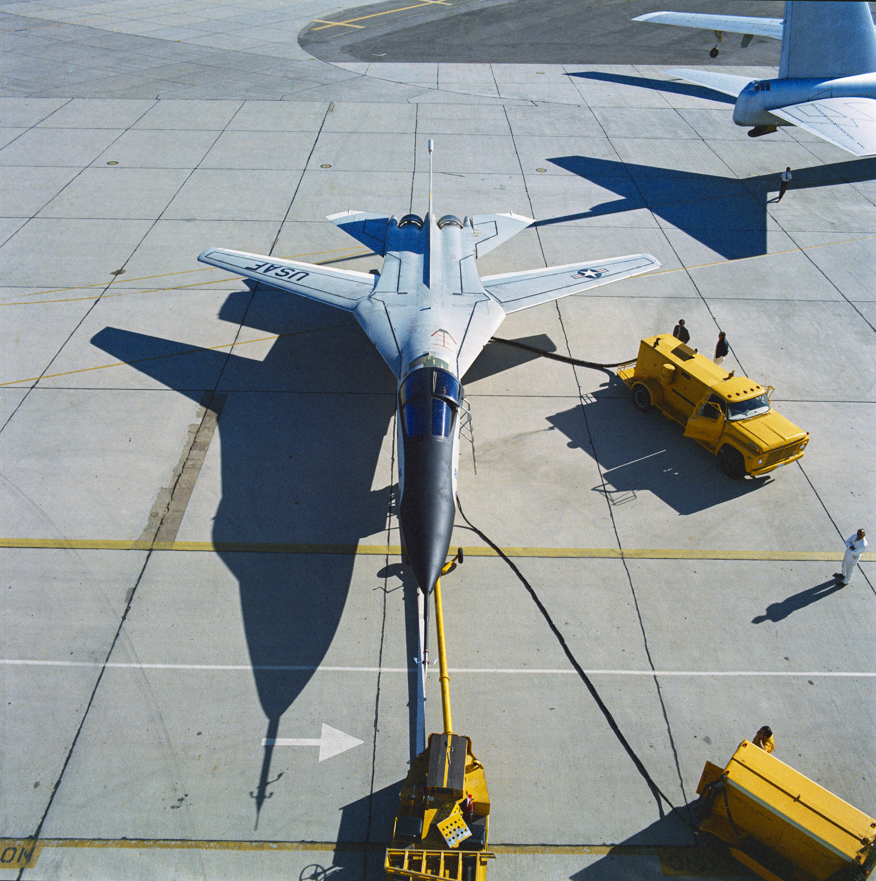
F-111B Fighter, Variable Sweep wings, wings swept forward, landing gear down. Slat experiments. The General Dynamics/Grumman F-111B was a long-range carrier-based interceptor aircraft that was planned to be a follow-on to the F-4 Phantom II. The F-111B was developed in the 1960s by General Dynamics in conjunction with Grumman for the United States Navy (USN) as part of the joint Tactical Fighter Experimental (TFX) with the United States Air Force (USAF) to produce a common fighter for the services that could perform a variety of missions.
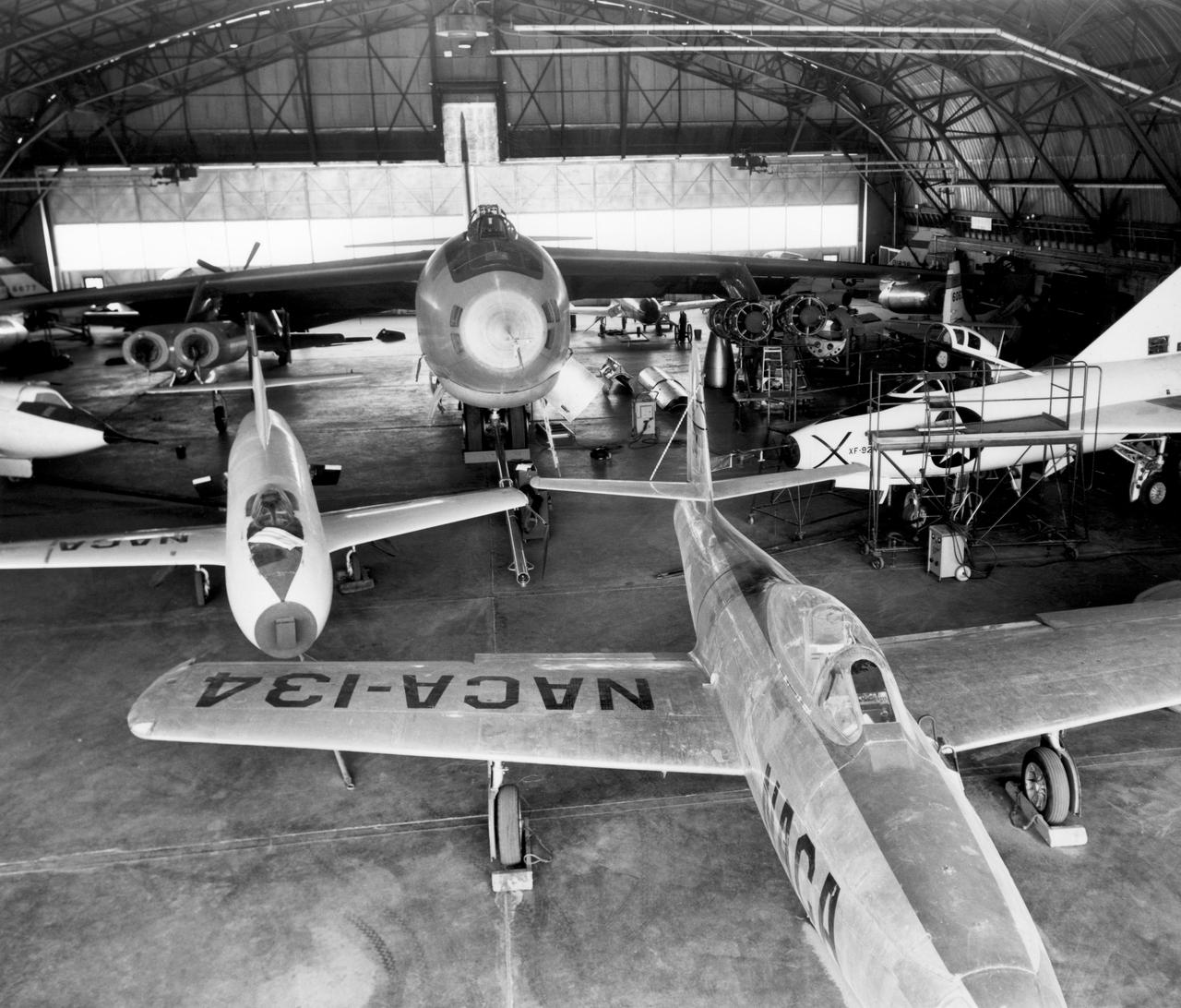
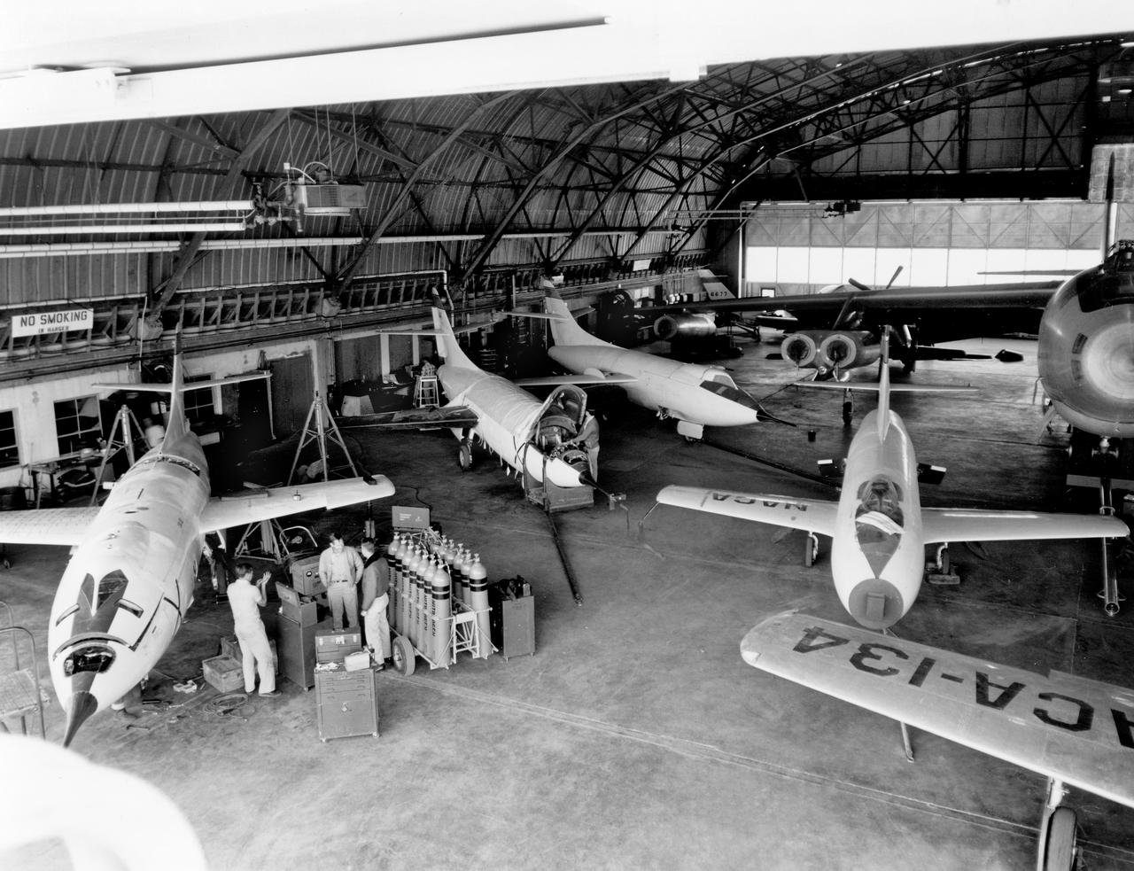
In the center foreground of this 1953 hangar photo is the YF-84A (NACA 134/Air Force 45-59490) used for vortex generator research. It arrived on November 28, 1949, and departed on April 21, 1954. Beside it is the third D-558-1 aircraft (NACA 142/Navy 37972). This aircraft was used for a total of 78 transonic research flights from April 1949 to June 1954. It replaced the second D-558-1, lost in the crash which killed Howard Lilly. Just visible on the left edge is the nose of the first D-558-2 (NACA 143/Navy 37973). Douglas turned the aircraft over to NACA on August 31, 1951, after the contractor had completed its initial test flights. NACA only made a single flight with the aircraft, on September 17, 1956, before the program was cancelled. In the center of the photo is the B-47A (NACA 150/Air Force 49-1900). The B-47 jet bomber, with its thin, swept-back wings, and six podded engines, represented the state of the art in aircraft design in the early 1950s. The aircraft undertook a number of research activities between May 1953 and its 78th and final research flight on November 22, 1957. The tests showed that the aircraft had a buffeting problem at speeds above Mach 0.8. Among the pilots who flew the B-47 were later X-15 pilots Joe Walker, A. Scott Crossfield, John B. McKay, and Neil A. Armstrong. On the right side of the B-47 is NACA's X-1 (Air Force 46-063). The second XS-1 aircraft built, it was fitted with a thicker wing than that on the first aircraft, which had exceeded Mach 1 on October 14, 1947. Flight research by NACA pilots indicated that this thicker wing produced 30 percent more drag at transonic speeds compared to the thinner wing on the first X-1. After a final flight on October 23, 1951, the aircraft was grounded due to the possibility of fatigue failure of the nitrogen spheres used to pressurize the fuel tanks. At the time of this photo, in 1953, the aircraft was in storage. In 1955, the aircraft was extensively modified, becoming the X-1E. In front o
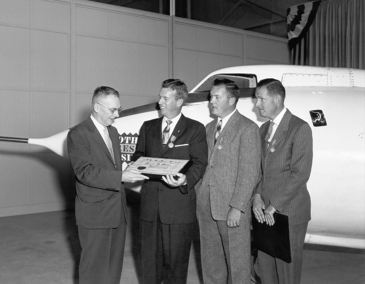
Hugh Dryden (far left) presents the NACA Exceptional Service Medal award at the NACA High Speed Flight Station. He awarded (L-R) Joe Walker (X-1A research pilot), Stan Butchart (pilot of the B-29 mothership),and Richard Payne (X-1A crew chief) in recognition of their research extending knowledge of swept wing flight.
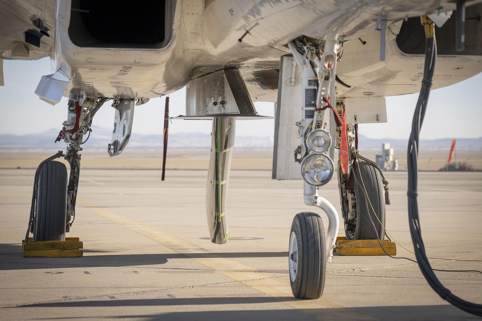
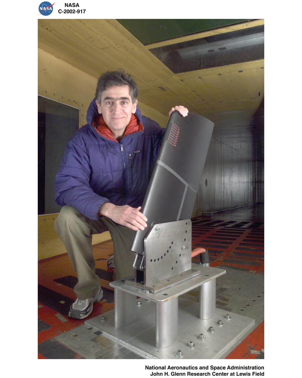
NASA’s Cross Flow Attenuated Natural Laminar Flow test article is mounted beneath the agency’s F-15 research aircraft ahead of the design’s high-speed taxi test on Tuesday, Jan. 12, 2026, at NASA’s Armstrong Flight Research Center in Edwards, California. The 3-foot-tall scale model is designed to increase a phenomenon known as laminar flow and reduce drag, improving efficiency in large, swept wings like those found on most commercial aircraft.
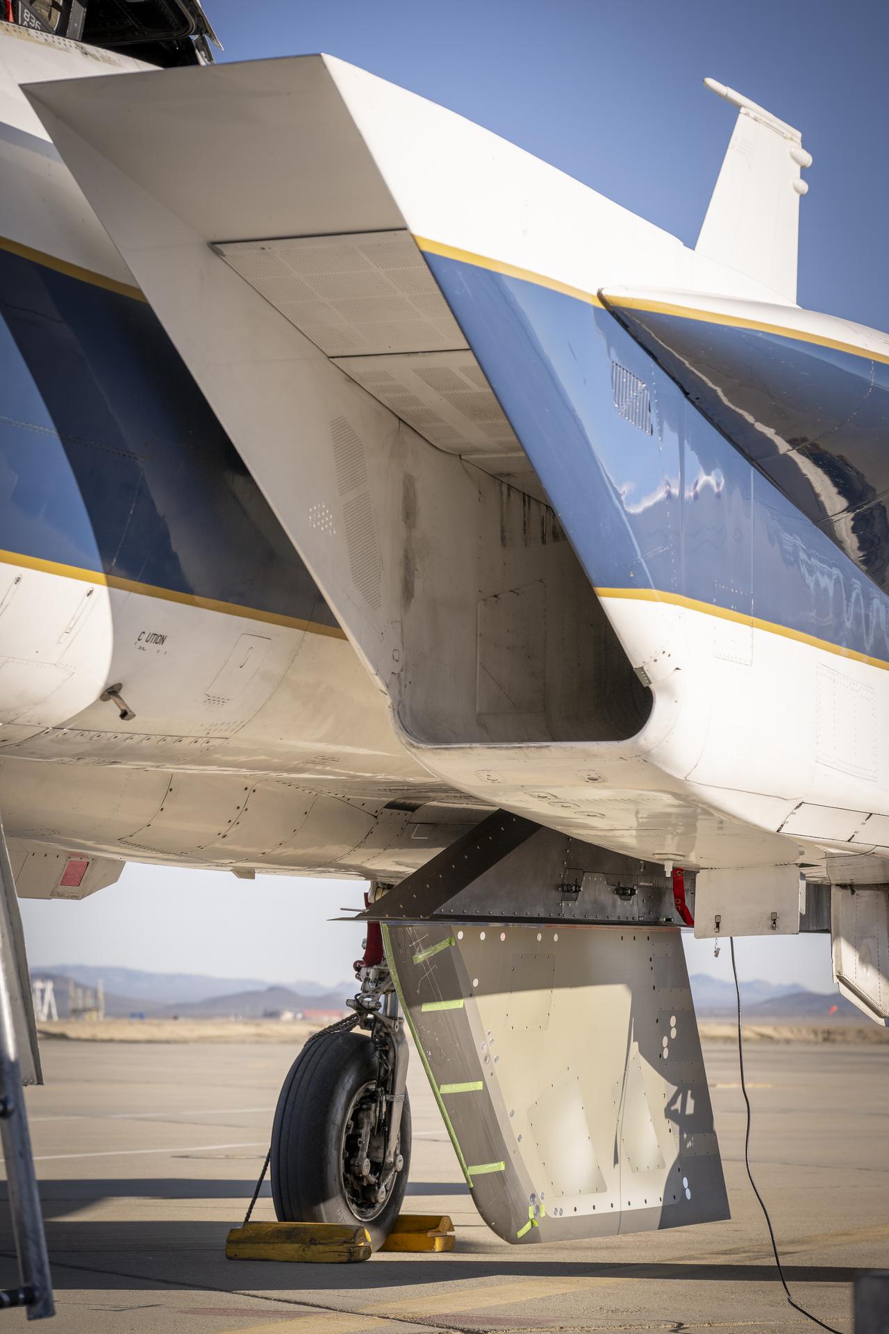
NASA’s Cross Flow Attenuated Natural Laminar Flow test article is mounted beneath the agency’s F-15 research aircraft ahead of the design’s high-speed taxi test on Tuesday, Jan. 12, 2026, at NASA’s Armstrong Flight Research Center in Edwards, California. The 3-foot-tall scale model is designed to increase a phenomenon known as laminar flow and reduce drag, improving efficiency in large, swept wings like those found on most commercial aircraft.
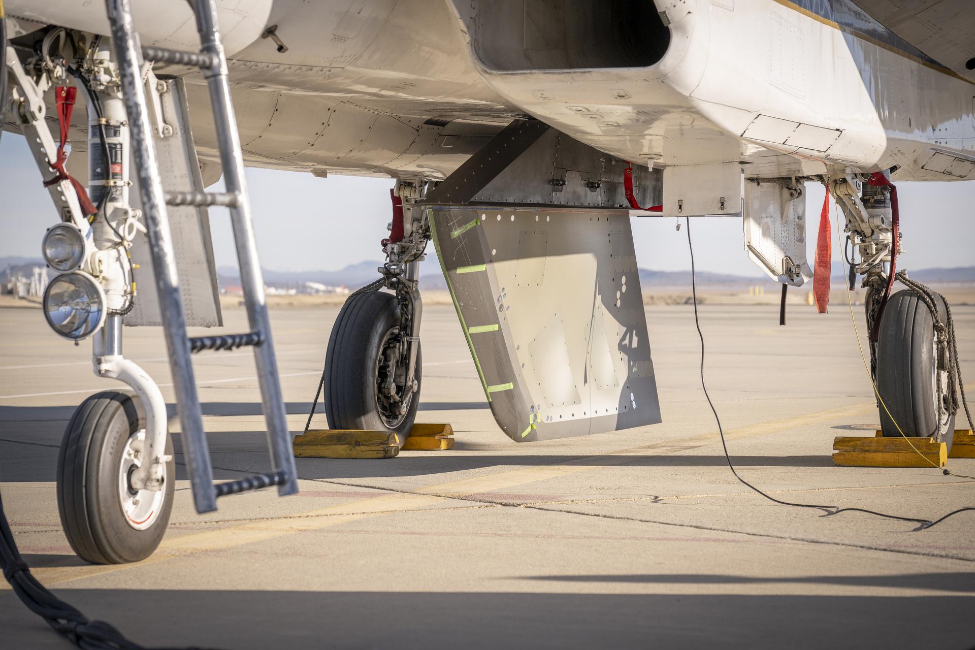
NASA’s Cross Flow Attenuated Natural Laminar Flow test article is mounted beneath the agency’s F-15 research aircraft ahead of the design’s high-speed taxi test on Tuesday, Jan. 12, 2026, at NASA’s Armstrong Flight Research Center in Edwards, California. The 3-foot-tall scale model is designed to increase a phenomenon known as laminar flow and reduce drag, improving efficiency in large, swept wings like those found on most commercial aircraft.
The aircraft in this 1953 photo of the National Advisory Committee for Aeronautics (NACA) hangar at South Base of Edwards Air Force Base showed the wide range of research activities being undertaken. On the left side of the hangar are the three D-558-2 research aircraft. These were designed to test swept wings at supersonic speeds approaching Mach 2. The front D-558-2 is the third built (NACA 145/Navy 37975). It has been modified with a leading-edge chord extension. This was one of a number of wing modifications, using different configurations of slats and/or wing fences, to ease the airplane's tendency to pitch-up. NACA 145 had both a jet and a rocket engine. The middle aircraft is NACA 144 (Navy 37974), the second built. It was all-rocket powered, and Scott Crossfield made the first Mach 2 flight in this aircraft on November 20, 1953. The aircraft in the back is D-558-2 number 1. NACA 143 (Navy 37973) was also carried both a jet and a rocket engine in 1953. It had been used for the Douglas contractor flights, then was turned over to the NACA. The aircraft was not converted to all-rocket power until June 1954. It made only a single NACA flight before NACA's D-558-2 program ended in 1956. Beside the three D-558-2s is the third D-558-1. Unlike the supersonic D-558-2s, it was designed for flight research at transonic speeds, up to Mach 1. The D-558-1 was jet-powered, and took off from the ground. The D-558-1's handling was poor as it approached Mach 1. Given the designation NACA 142 (Navy 37972), it made a total of 78 research flights, with the last in June 1953. In the back of the hangar is the X-4 (Air Force 46-677). This was a Northrop-built research aircraft which tested a swept wing design without horizontal stabilizers. The aircraft proved unstable in flight at speeds above Mach 0.88. The aircraft showed combined pitching, rolling, and yawing motions, and the design was considered unsuitable. The aircraft, the second X-4 built, was then used as a pilot traine
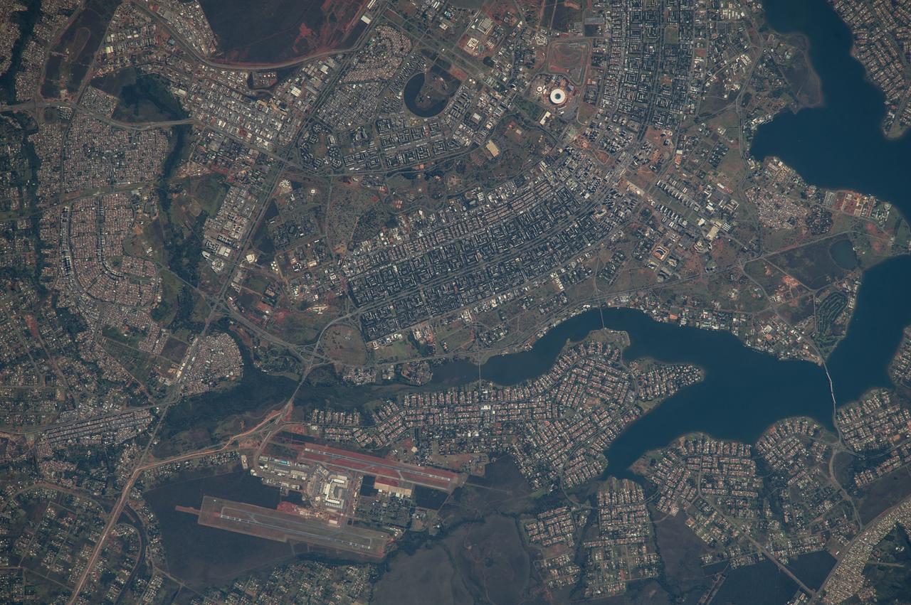
ISS040-E-005839 (28 May 2014) --- The Brasilia World Cup Stadium (top center) is featured in this image photographed by an Expedition 40 crew member on the International Space Station on May 28, 2014. Brazil?s national football stadium, the Estado Nacional, lies near the heart of the capital city of Brasilia. The new roof appears as a brilliant white ring in this image. The stadium is one of Brasilia?s largest buildings. Renovation began in 2010 and it is now the second most expensive stadium in the world, after Wembley Stadium in London, UK. To accommodate expected World Cup fans from all over the world, renovations for all modes of transportation, particularly airports, have been put in place in Brasilia and other host cities. Brasilia?s international airport can be seen lower left on the far side of Lake Paranoa. Brasilia is widely known for its modern building designs and city layout. Space station crew members have the best view of the city?s well-known ?swept wing? city layout ? giving the sense of a flying bird ? expressed in the curves of the boulevards (top). The stadium occupies the city center between the wings. The President Juscelino Kubitschek Bridge crosses the lake at bottom right. Its 1200-meter span gives scale to the city and stadium.
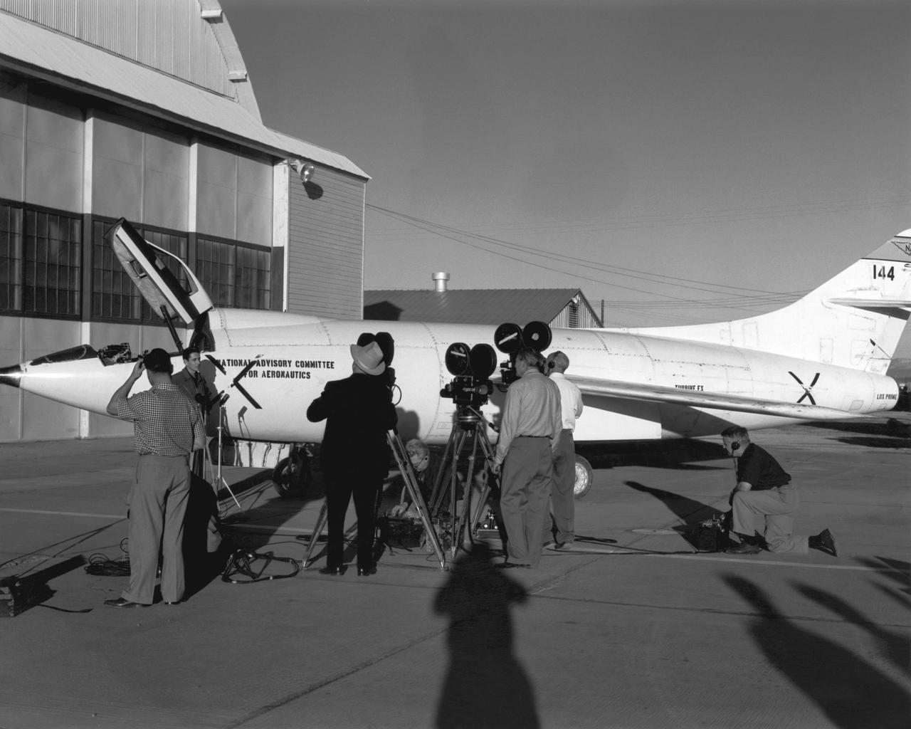
Scott Crossfield talks to newsmen in front of NACA South Base hangar after his first flight to Mach 2 in the Douglas D-558-2.
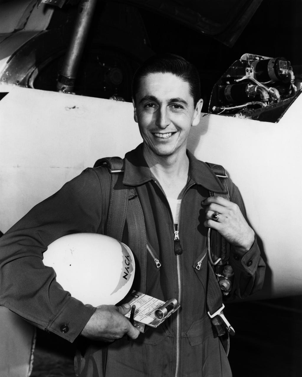
NACA pilot A. Scott Crossfield next to the D-558-2 after first Mach 2 flight.
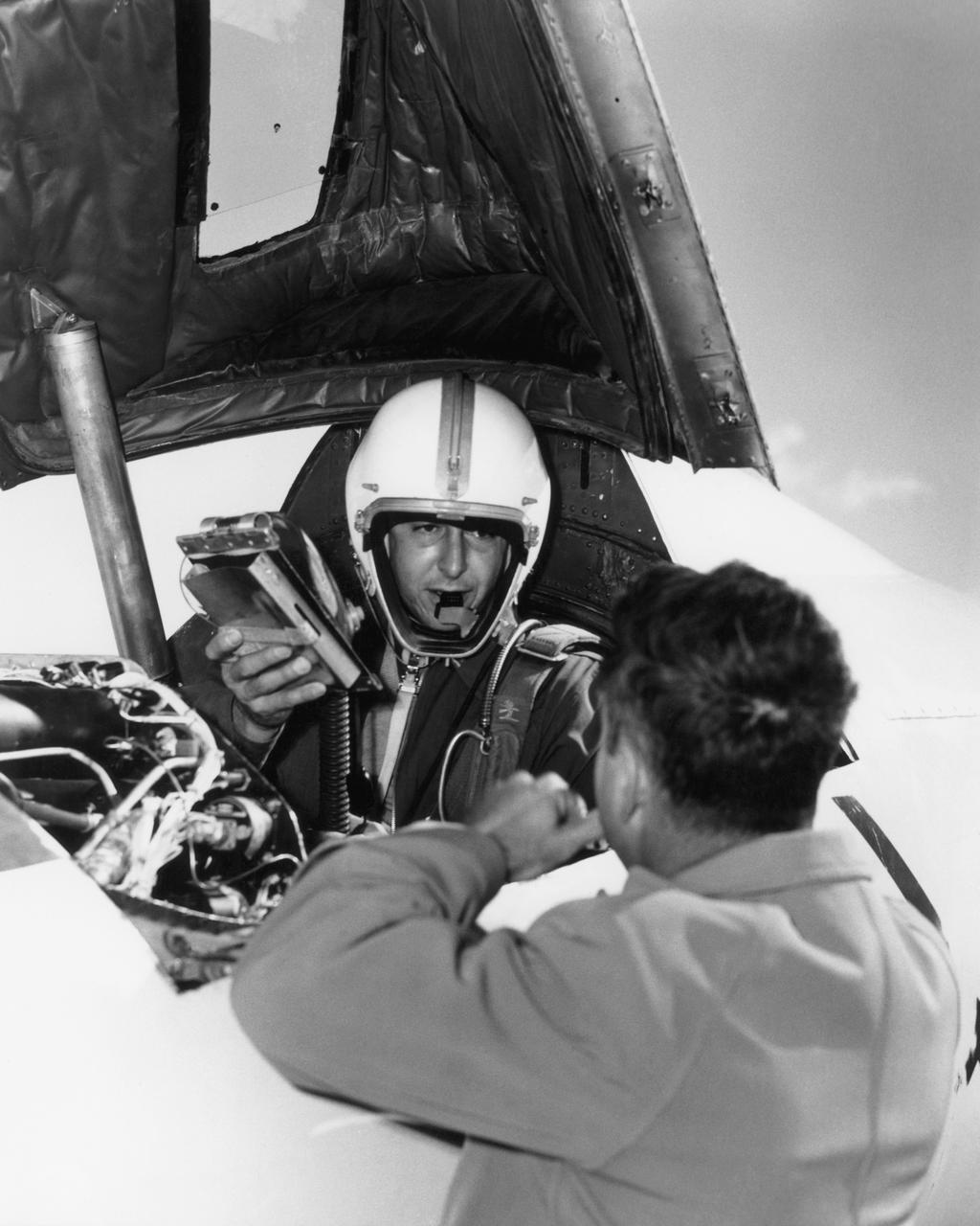
Scott Crossfield in cockpit of the Douglas D-558-2 after first Mach 2 flight.

The NASA Dryden 747 Shuttle Carrier Aircraft crew poses in an engine inlet; Standing L to R - aircraft mechanic John Goleno and SCA Team Leader Pete Seidl; Kneeling L to R - aircraft mechanics Todd Weston and Arvid Knutson, and avionics technician Jim Bedard NASA uses two modified Boeing 747 jetliners, originally manufactured for commercial use, as Space Shuttle Carrier Aircraft (SCA). One is a 747-100 model, while the other is designated a 747-100SR (short range). The two aircraft are identical in appearance and in their performance as Shuttle Carrier Aircraft. The 747 series of aircraft are four-engine intercontinental-range swept-wing "jumbo jets" that entered commercial service in 1969. The SCAs are used to ferry space shuttle orbiters from landing sites back to the launch complex at the Kennedy Space Center, and also to and from other locations too distant for the orbiters to be delivered by ground transportation. The orbiters are placed atop the SCAs by Mate-Demate Devices, large gantry-like structures which hoist the orbiters off the ground for post-flight servicing, and then mate them with the SCAs for ferry flights.
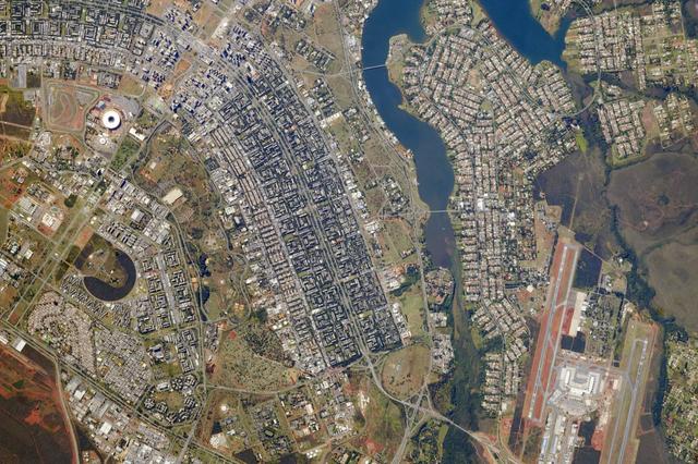
Brazil’s national football stadium, the Estado Nacíonal, lies near the heart of the capital city of Brasília. The roof appears as a brilliant white ring in this photograph taken from the International Space Station. The stadium is one of Brasília’s largest buildings. Renovation began in 2010, and it is now the second most expensive stadium in the world after Wembley Stadium in London. To accommodate World Cup fans visiting from all over the world, renovations were made to nearly all modes of transportation—particularly airports—in Brasília and other host cities. Brasília’s international airport is visible at lower right, on the far side of Lake Paranoá. (Note that the image is rotated so that north is to the left.) Brasília is widely known for its modern building designs and city layout. Astronauts have the best view of the city’s well-known “swept wing” city layout, which takes the form of a flying bird that is expressed in the curves of the boulevards (image left). The stadium occupies the city center, between the wings. Credit: ISS Read more/high res: <a href="http://earthobservatory.nasa.gov/NaturalHazards/view.php?id=83866&src=nha" rel="nofollow">earthobservatory.nasa.gov/NaturalHazards/view.php?id=8386...</a> Credit: <b><a href="http://www.earthobservatory.nasa.gov/" rel="nofollow"> NASA Earth Observatory</a></b> <b><a href="http://www.nasa.gov/audience/formedia/features/MP_Photo_Guidelines.html" rel="nofollow">NASA image use policy.</a></b> <b><a href="http://www.nasa.gov/centers/goddard/home/index.html" rel="nofollow">NASA Goddard Space Flight Center</a></b> enables NASA’s mission through four scientific endeavors: Earth Science, Heliophysics, Solar System Exploration, and Astrophysics. Goddard plays a leading role in NASA’s accomplishments by contributing compelling scientific knowledge to advance the Agency’s mission. <b>Follow us on <a href="http://twitter.com/NASAGoddardPix" rel="nofollow">Twitter</a></b> <b>Like us on <a href="http://www.facebook.com/pages/Greenbelt-MD/NASA-Goddard/395013845897?ref=tsd" rel="nofollow">Facebook</a></b> <b>Find us on <a href="http://instagram.com/nasagoddard?vm=grid" rel="nofollow">Instagram</a></b>
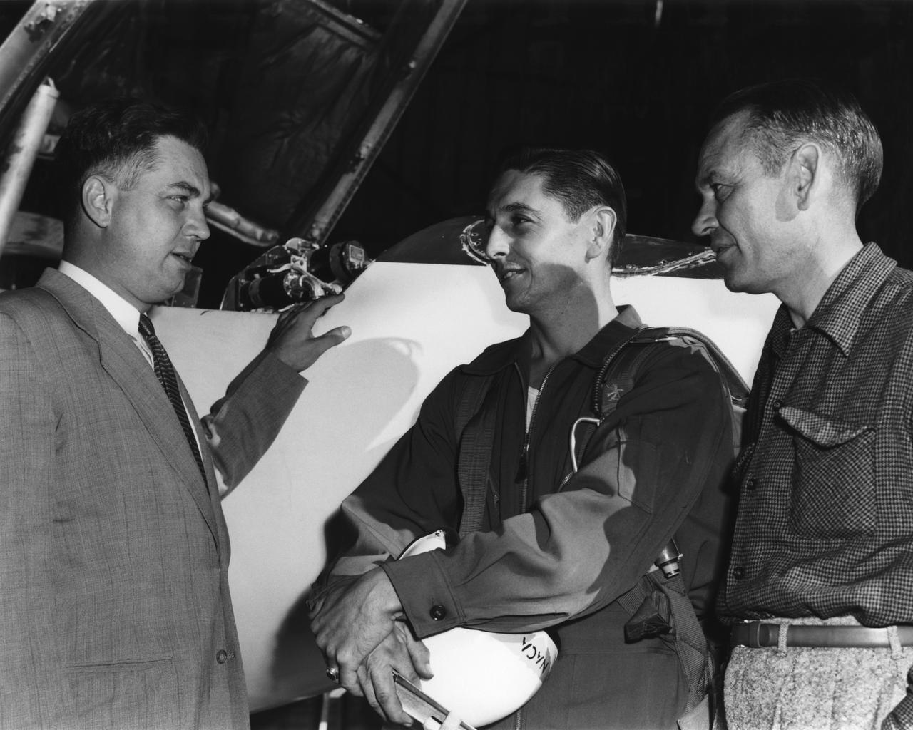
High-Speed Research Station Director Walter C. Williams, NACA pilot A. Scott Crossfield, and Director of Flight Operations Joe Vensel in front of the Douglas D-558-2 after the first Mach 2 flight.
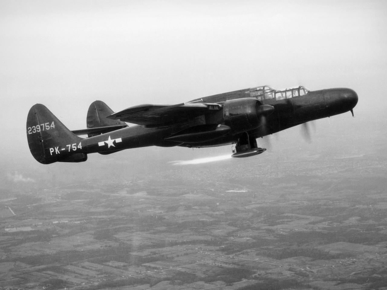
The National Advisory Committee for Aeronautics (NACA) Lewis Flight Propulsion Laboratory obtained a Northrop P-61 Black Widow in October 1945 and modified it to serve as a subsonic testbed for ramjet engines and swept-wing aircraft models. The P-61 was developed during World War II specifically for nighttime attacks. It was the largest and heaviest US fighter in the war. The P-61’s unique design included an abbreviated fuselage and twin booms that were joined by a single tail. To facilitate its nighttime missions, the P-61 was painted black and carried a radar system in its nose. It was designed so the crew could perform their flight and tracking tasks in complete darkness. NACA Lewis was in the midst of a massive research effort on ramjets when it acquired the Black Widow. Researchers used the aircraft to accelerate the ramjet until it reached a velocity at which it could be ignited. A ramjet can be seen being fired underneath the aircraft in this photograph. Sensors and instrumentation fed data from the ramjet to the pilot and researchers on the ground. The NACA researchers created a rectangular ramjet with a V-shaped gutter flameholder. The researchers installed the ramjet on the P-61 and flew it at subsonic speeds over a range of altitudes up to 29,000 feet. The ramjet had been previously tested at low speeds on a test stand on the hangar apron. The rectangular ramjet was also used to study different types of flameholders and nozzles used to spray fuel into the combustion chamber. The Black Widow was transferred from Lewis in October 1948.
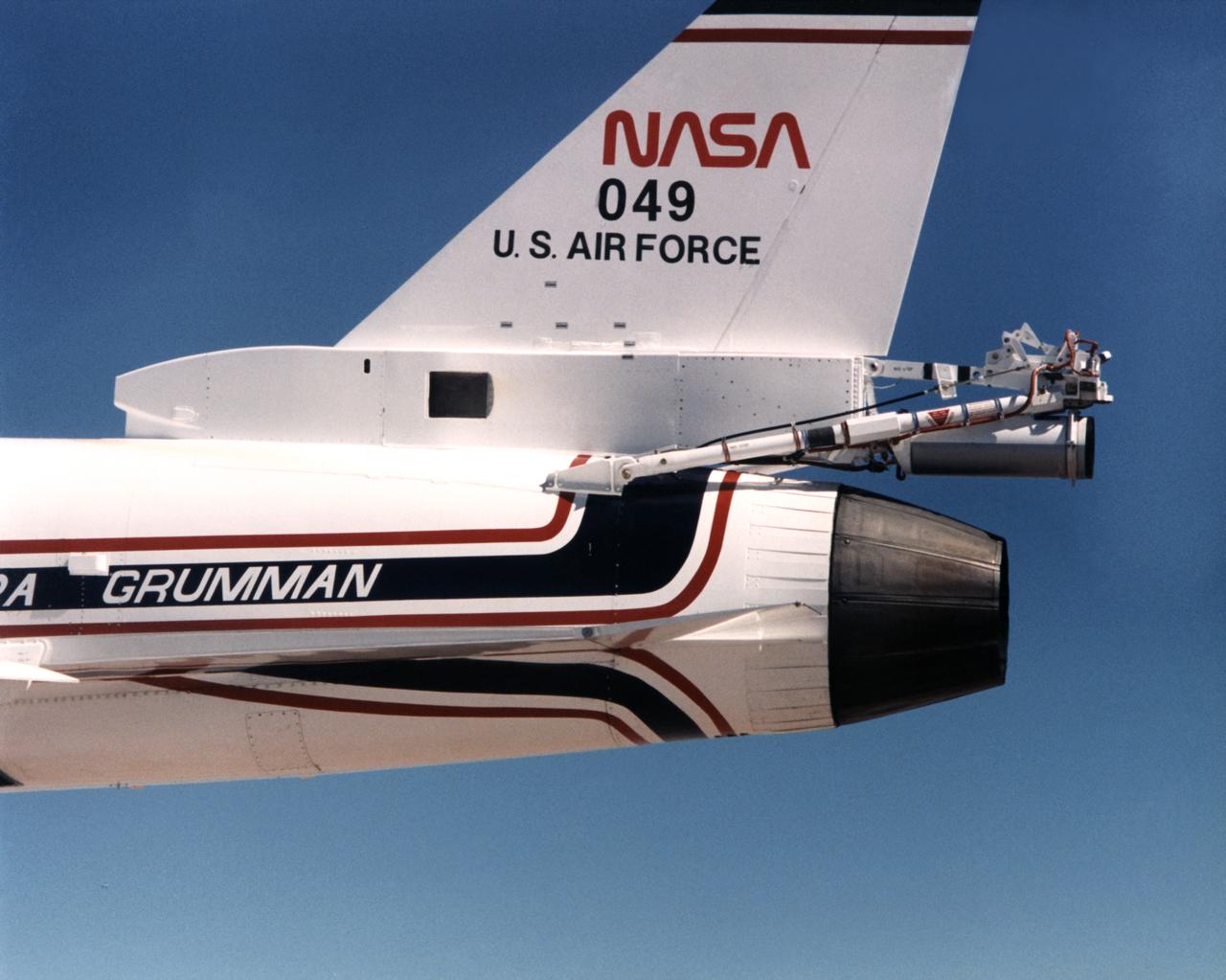
Because the number two X-29 at NASA's Ames-Dryden Flight Research Facility (later the Dryden Flight Research Center) flew at higher angles of attack than the number one aircraft, it required a spin chute system for safety. The system deployed a parachute for recovery of the aircraft if it inadvertently entered an uncontrolled spin. Most of the components of the spin chute system were located on a truss at the aft end of the aircraft. In addition, there were several cockpit modifications to facilitate use of the chute. The parachute was made of nylon and was of the conical ribbon type.
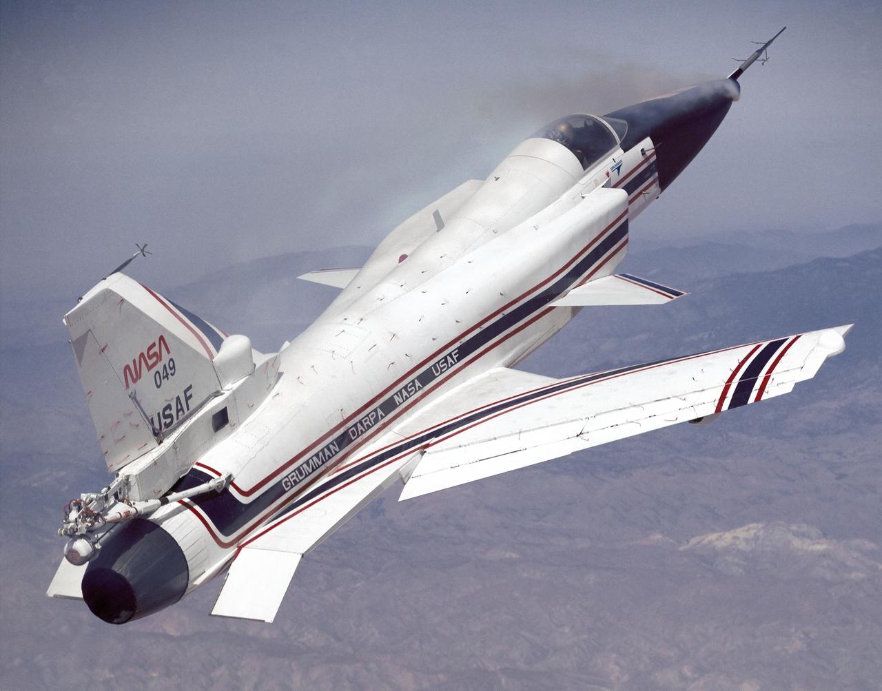
This photo shows the X-29 during a 1991 research flight. Smoke generators in the nose of the aircraft were used to help researchers see the behavior of the air flowing over the aircraft. The smoke here is demonstrating forebody vortex flow. This mission was flown September 10, 1991, by NASA research pilot Rogers Smith.