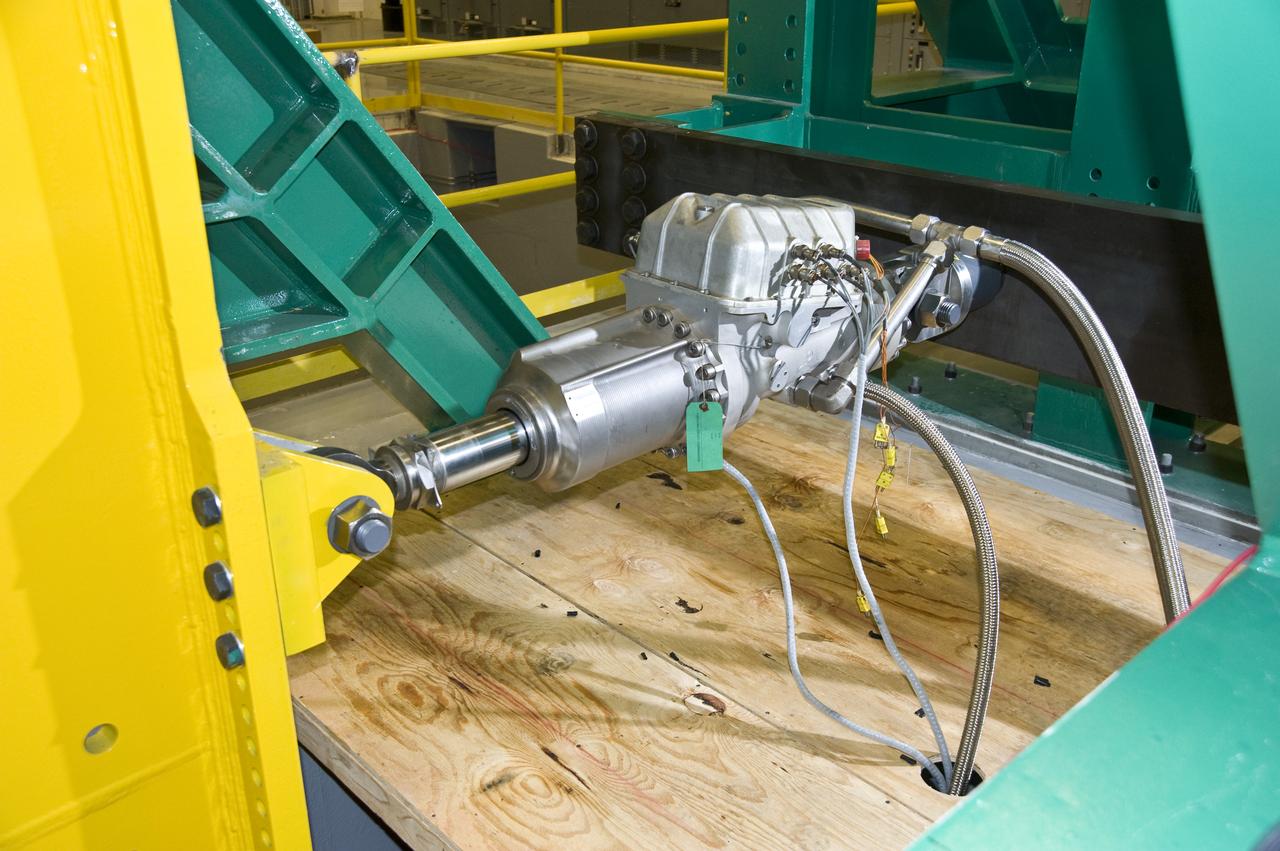
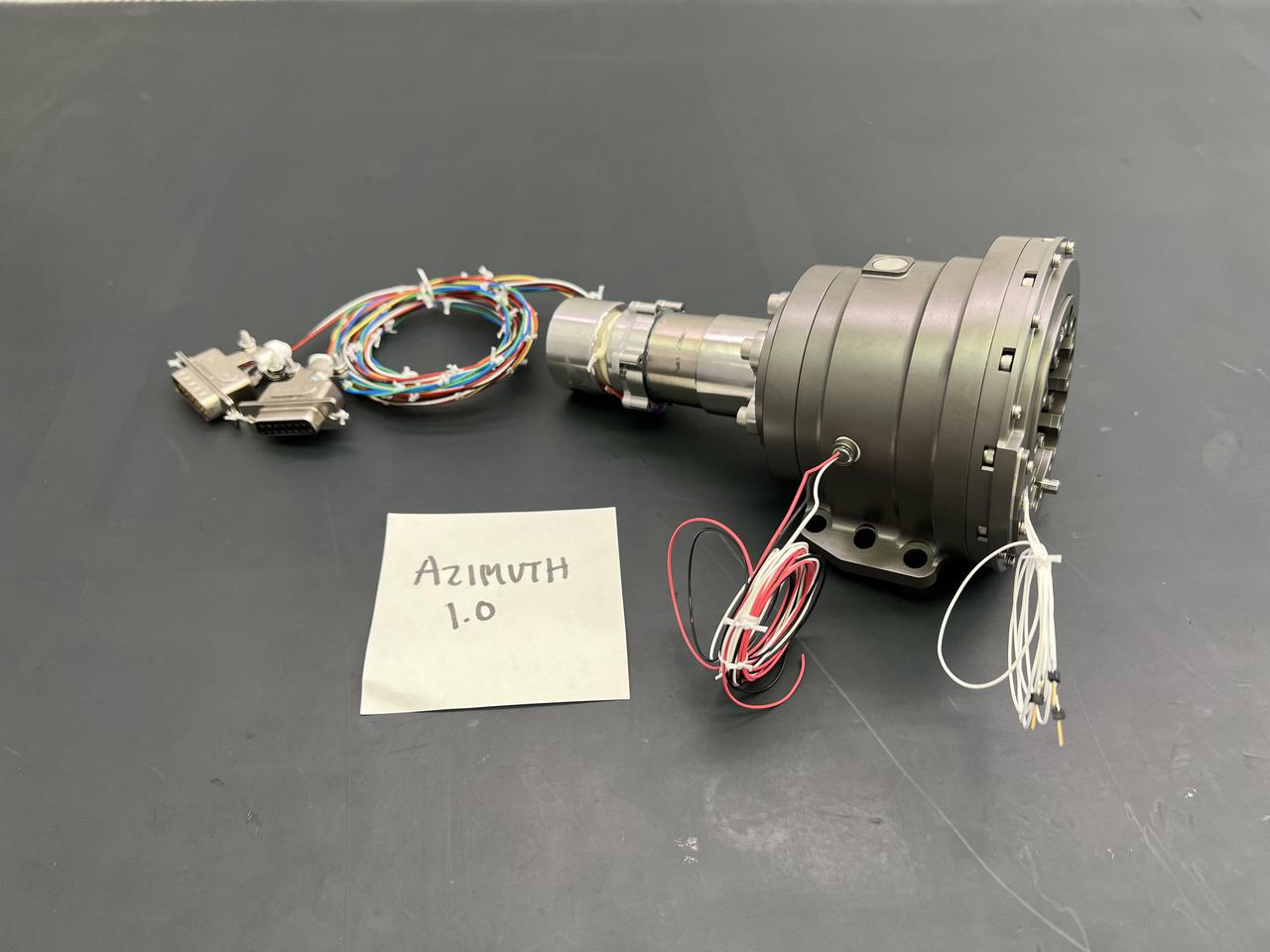
THRUST VECTOR CONTROL (TVC) TEST LAB TEST ACTUATOR
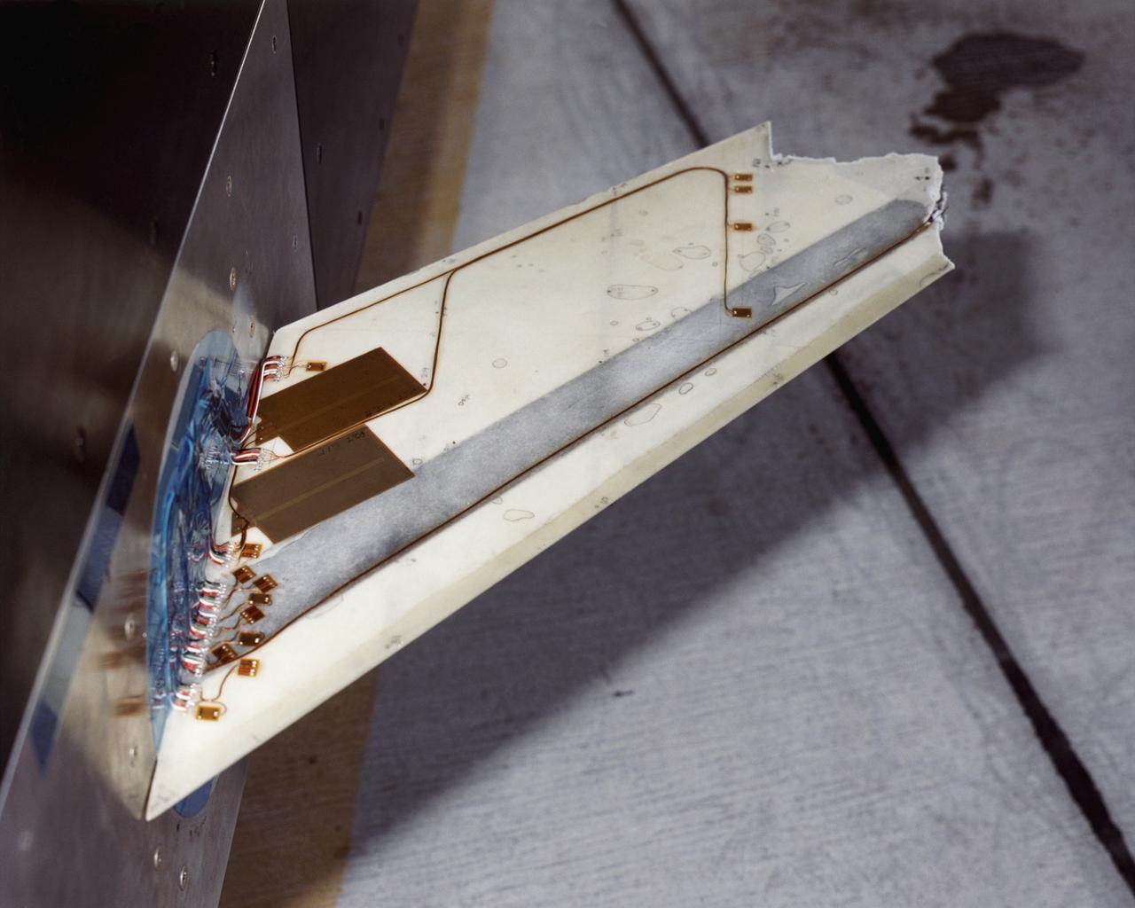
The Aerostructures Test Wing (ATW), which consisted of an 18-inch carbon fiber test wing with surface-mounted piezoelectric strain actuators, following intentional failure on its final flight
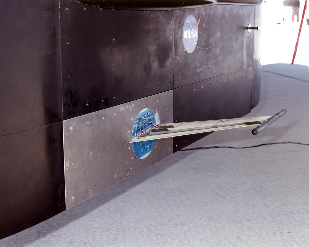
The Aerostructures Test Wing (ATW), which consisted of an 18-inch carbon fiber test wing with surface-mounted piezoelectric strain actuators, was mounted on a special ventral flight test fixture and flown on Dryden's F-15B Research Testbed aircraft
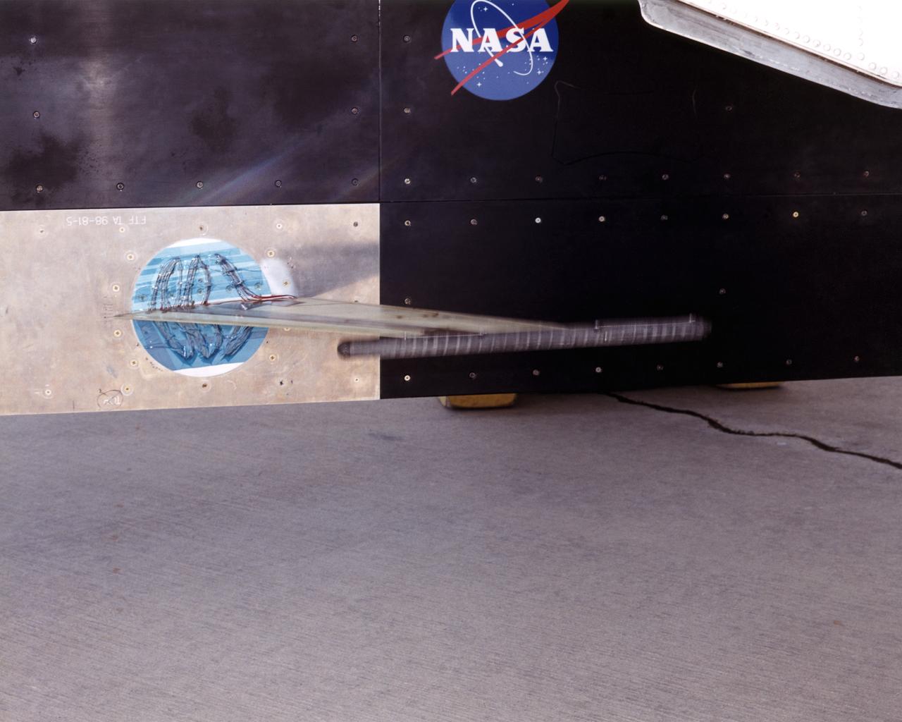
The Aerostructures Test Wing (ATW) experiment, which consisted of an 18-inch carbon fiber test wing with surface-mounted piezoelectric strain actuators, undergoing ground testing prior to flight on Dryden's F-15B Research Testbed aircraft
N-206 12ft W.T. ADTE Project (Aeronautics Design and Test Environment) Old TPC valve actuators
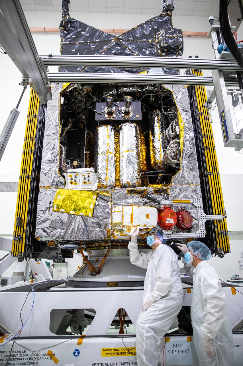
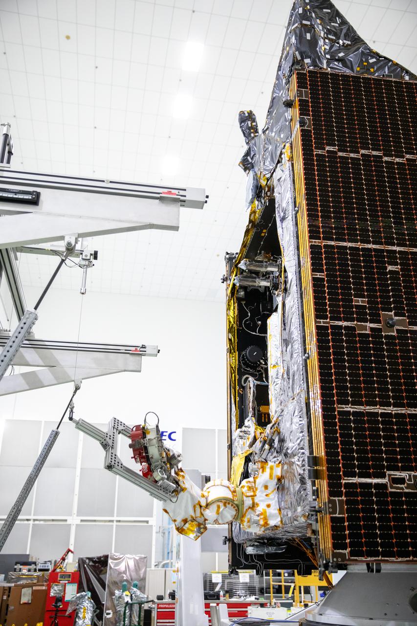
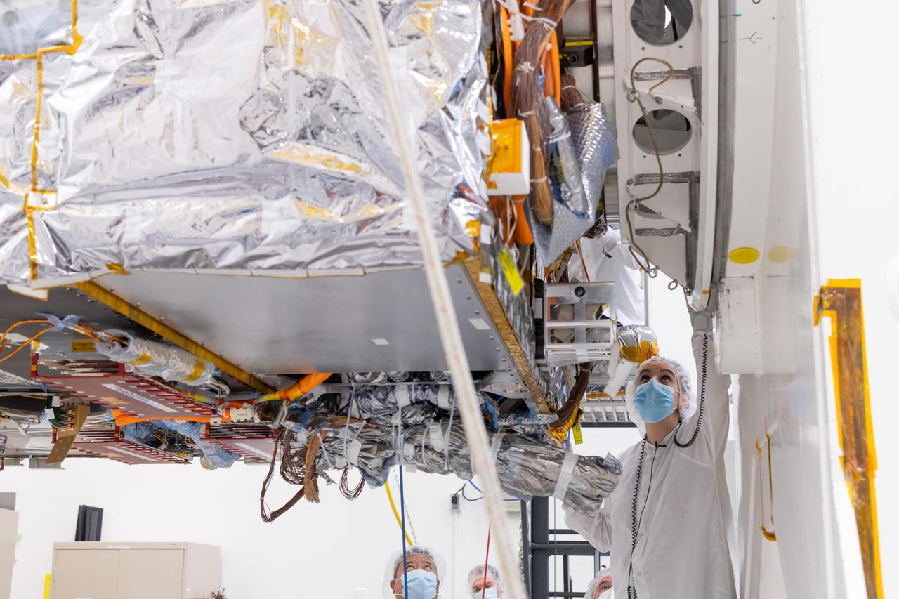
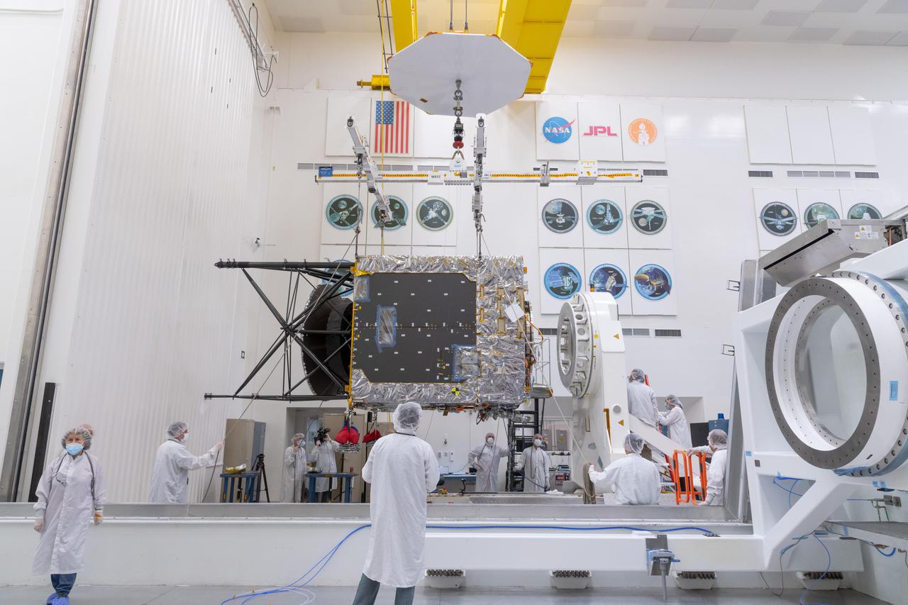
A team of engineers and technicians work on deploying and stowing stationary plasma thrusters (SPT) on NASA's Psyche spacecraft inside the Astrotech Space Operations Facility near the agency’s Kennedy Space Center in Florida on Aug. 4, 2023. This is part of the assembly, test, and launch operations preparations. The SPT are on a dual axis positioning mechanism (DAPM), and together they make a DSM, or DAPM-actuated SPT module. Psyche will launch atop a SpaceX Falcon Heavy rocket from Launch Complex 39A at Kennedy. Launch is targeted for Oct. 5, 2023. Riding with Psyche is a pioneering technology demonstration, NASA’s Deep Space Optical Communications (DSOC) experiment.
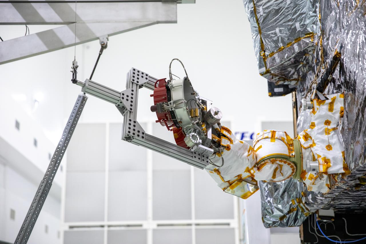
A team of engineers and technicians work on deploying and stowing stationary plasma thrusters (SPT) on NASA's Psyche spacecraft inside the Astrotech Space Operations Facility near the agency’s Kennedy Space Center in Florida on Aug. 4, 2023. This is part of the assembly, test, and launch operations preparations. The SPT are on a dual axis positioning mechanism (DAPM), and together they make a DSM, or DAPM-actuated SPT module. Psyche will launch atop a SpaceX Falcon Heavy rocket from Launch Complex 39A at Kennedy. Launch is targeted for Oct. 5, 2023. Riding with Psyche is a pioneering technology demonstration, NASA’s Deep Space Optical Communications (DSOC) experiment.
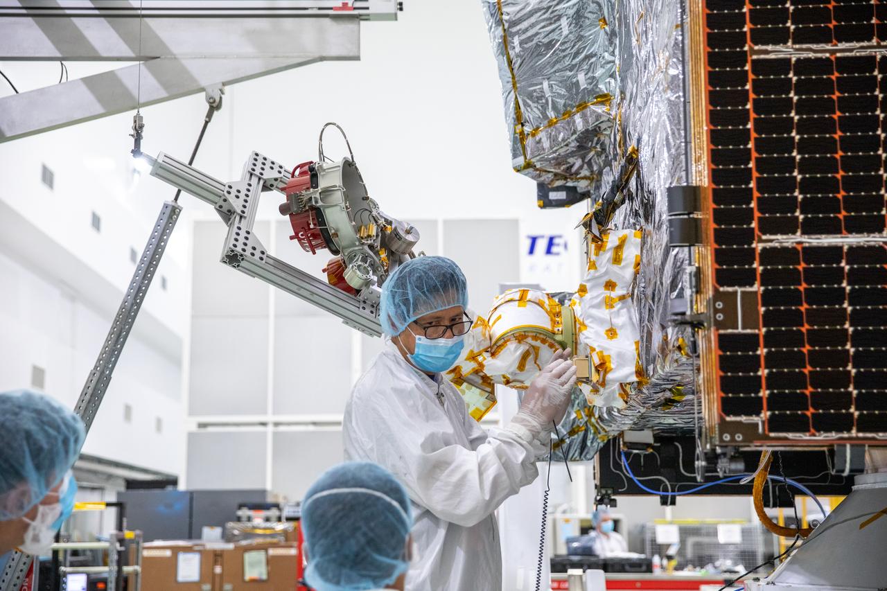
A team of engineers and technicians work on deploying and stowing stationary plasma thrusters (SPT) on NASA's Psyche spacecraft inside the Astrotech Space Operations Facility near the agency’s Kennedy Space Center in Florida on Aug. 4, 2023. This is part of the assembly, test, and launch operations preparations. The SPT are on a dual axis positioning mechanism (DAPM), and together they make a DSM, or DAPM-actuated SPT module. Psyche will launch atop a SpaceX Falcon Heavy rocket from Launch Complex 39A at Kennedy. Launch is targeted for Oct. 5, 2023. Riding with Psyche is a pioneering technology demonstration, NASA’s Deep Space Optical Communications (DSOC) experiment.
A team of engineers and technicians work on deploying and stowing stationary plasma thrusters (SPT) on NASA's Psyche spacecraft inside the Astrotech Space Operations Facility near the agency’s Kennedy Space Center in Florida on Aug. 4, 2023. This is part of the assembly, test, and launch operations preparations. The SPT are on a dual axis positioning mechanism (DAPM), and together they make a DSM, or DAPM-actuated SPT module. Psyche will launch atop a SpaceX Falcon Heavy rocket from Launch Complex 39A at Kennedy. Launch is targeted for Oct. 5, 2023. Riding with Psyche is a pioneering technology demonstration, NASA’s Deep Space Optical Communications (DSOC) experiment.
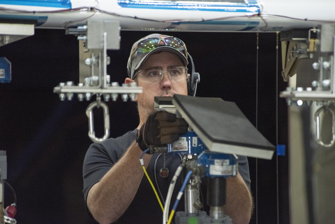
Ray Sadler adjusts hydraulic actuators with pads to the wing of the X-57 distributed electric aircraft wing at NASA's Armstrong Flight Research Center in California. Tests increased confidence in the wing's durability and calibrated installed strain gauges for inflight load monitoring of the wing.
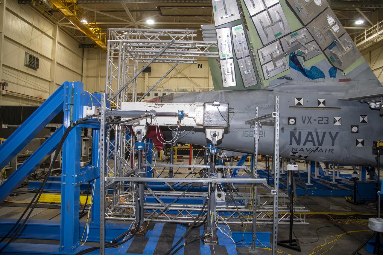
– Hydraulic actuators are pinned to horizontal tail test fixture for testing a F/A-18E from the Naval Air Systems Command (NAVAIR) in Patuxent River, Maryland. The aircraft is in NASA’s Armstrong Flight Research Center Flight Loads Laboratory in Edwards, California, for the center’s biggest load calibrations tests. This testing is needed before the aircraft can serve as a test vehicle for determining if it can safely manage maneuvers and proposed upgrades.
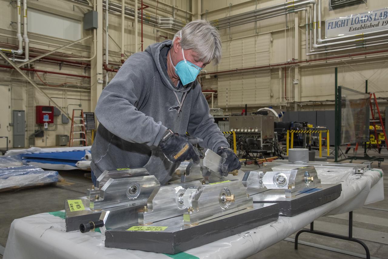
Assembled test structures called whiffle trees, which are needed to distribute prescribed hydraulic actuator loads, are attached to load pads to test the F/A-18E from the Naval Air Systems Command (NAVAIR) in Patuxent River, Maryland. The aircraft is in NASA’s Armstrong Flight Research Center Flight Loads Laboratory in Edwards, California, for the center’s biggest load calibrations tests. This testing is needed before the aircraft can serve as a test vehicle for determining if it can safely manage maneuvers and proposed upgrades.
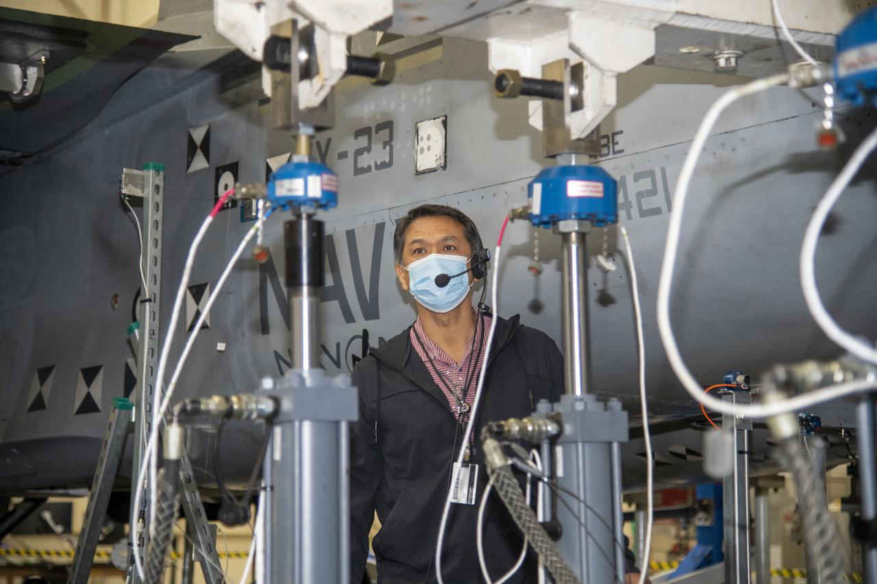
Larry Hudson does an inspection after the actuator on the F/A-18E from the Naval Air Systems Command (NAVAIR) in Patuxent River, Maryland, is pinned to the horizontal tail load test fixture. The aircraft is in NASA’s Armstrong Flight Research Center Flight Loads Laboratory in Edwards, California, for the center’s biggest load calibrations tests. This testing is needed before the aircraft can serve as a test vehicle for determining if it can safely manage maneuvers and proposed upgrades.
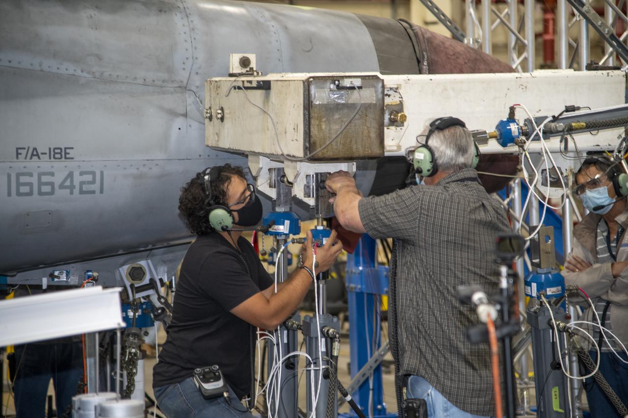
The actuator on the F/A-18E from the Naval Air Systems Command (NAVAIR) in Patuxent River, Maryland, is pinned to the horizontal tail load test fixture. The aircraft is in NASA’s Armstrong Flight Research Center Flight Loads Laboratory in Edwards, California, for the center’s biggest load calibrations tests. This testing is needed before the aircraft can serve as a test vehicle for determining if it can safely manage maneuvers and proposed upgrades.
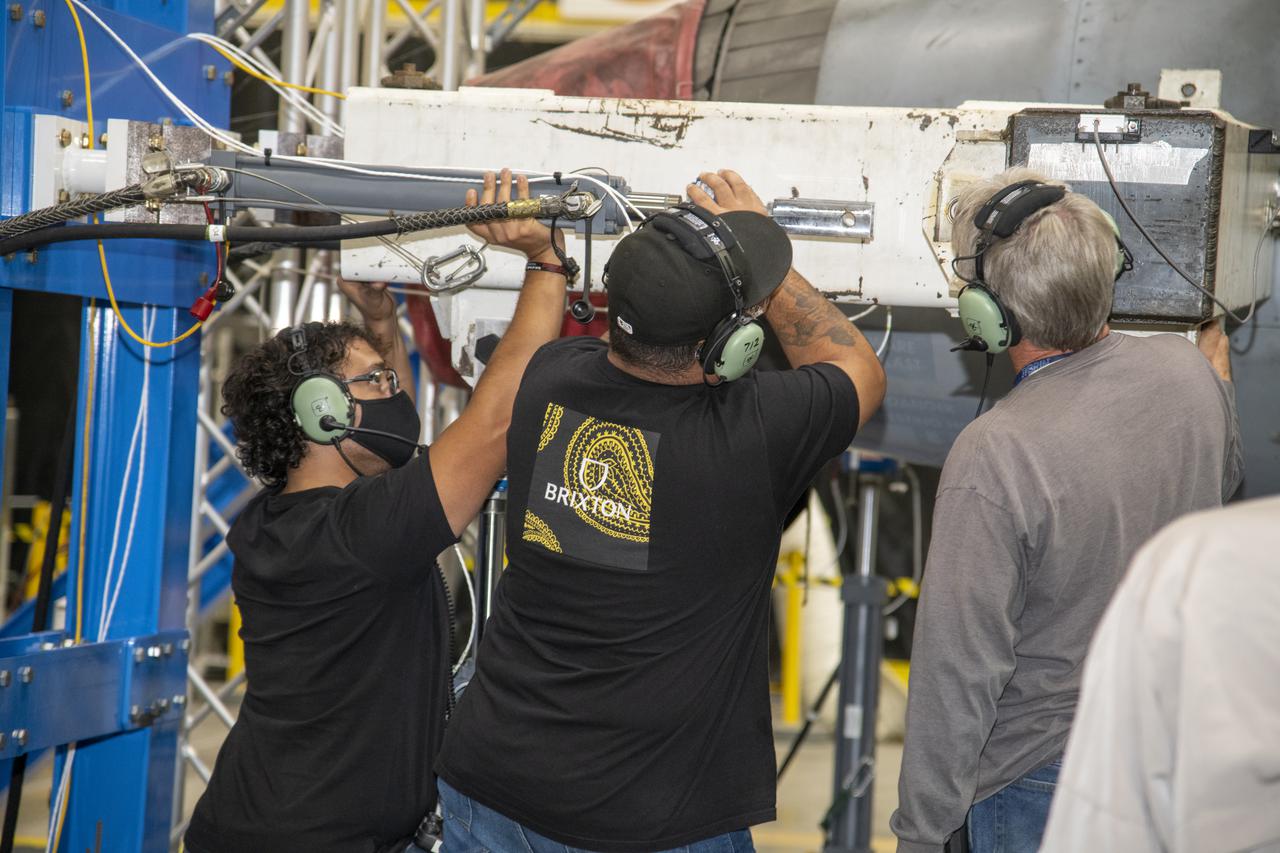
The actuator on the F/A-18E from the Naval Air Systems Command (NAVAIR) in Patuxent River, Maryland, is positioned for pinning to the horizontal tail load test fixture. The aircraft is in NASA’s Armstrong Flight Research Center Flight Loads Laboratory in Edwards, California, for the center’s biggest load calibrations tests. This testing is needed before the aircraft can serve as a test vehicle for determining if it can safely manage maneuvers and proposed upgrades.
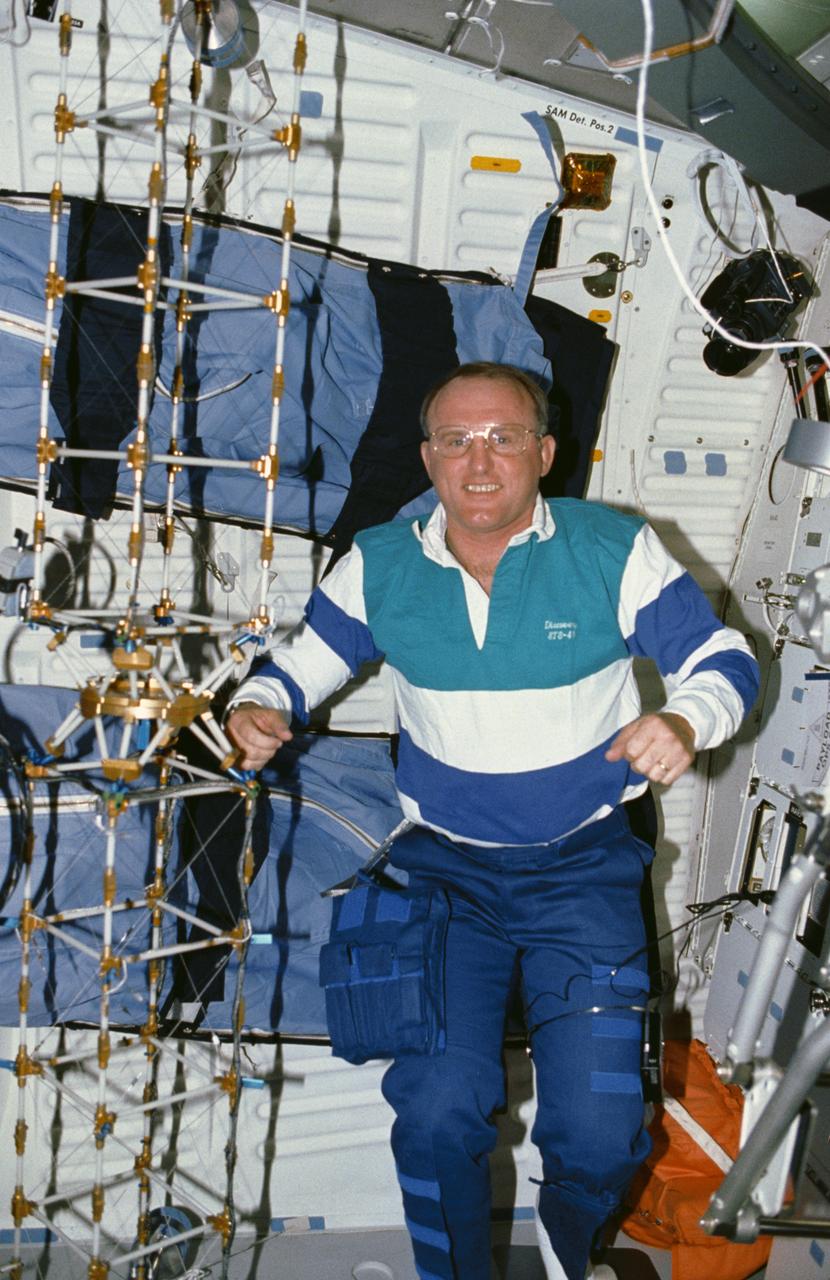
STS048-10-023 (16 Sept 1991) --- Astronaut James F. Buchli poses with the structural test article (STA), a model of the space station truss structure. The STA is part of the middeck zero gravity dynamics experiment (MODE). MODE was designed to study the vibration characteristics of the jointed truss structure. The structural test article includes four strain gauges and eleven accelerometers and is vibrated by an actuator. Assembled by crewmembers in the Shuttle orbiter's middeck, the device is about 72 inches long with an 8-inch square cross section.
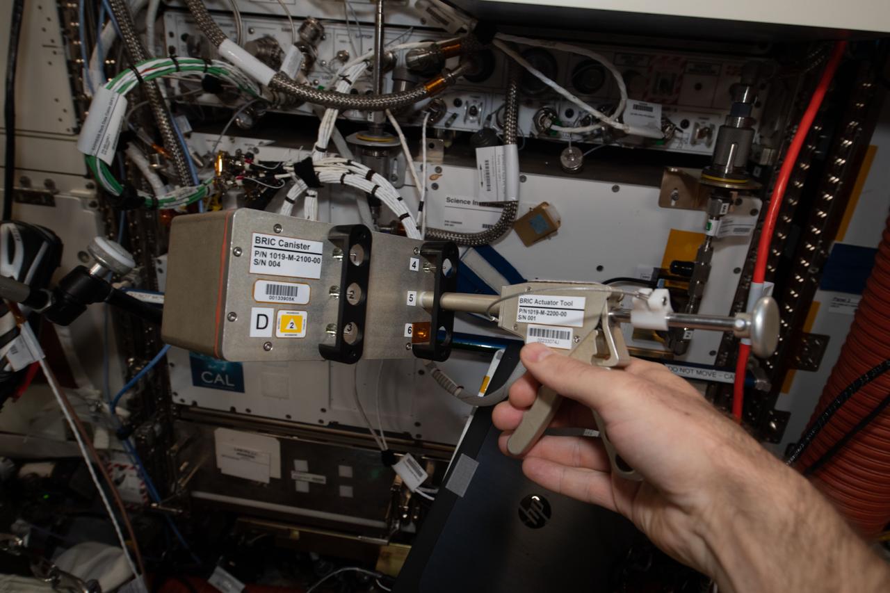
iss065e094066 (6/9/2021) --- A close-up view of the a BRIC-24 Canister and actuator tool. Biological Research In Canisters-24 (BRIC-24) tests how space affects organelle contacts and vacuole fusion in plants, systems that may be important for plant gravity sensing and response. Vacuoles are organelles in plant cells that have important functions.
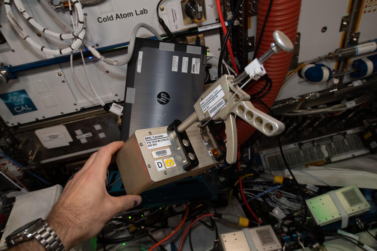
iss065e094062 (6/9/2021) --- A close-up view of the a BRIC-24 Canister and actuator tool. Biological Research In Canisters-24 (BRIC-24) tests how space affects organelle contacts and vacuole fusion in plants, systems that may be important for plant gravity sensing and response. Vacuoles are organelles in plant cells that have important functions.
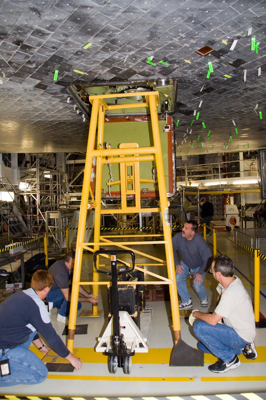
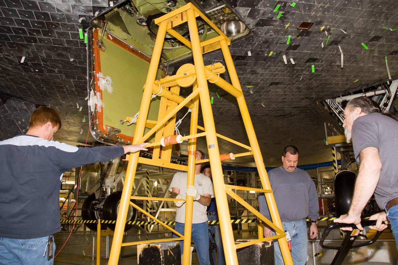
CAPE CANAVERAL, Fla. - In Orbiter Processing Facility 1 at NASA's Kennedy Space Center in Florida, United Space Alliance technicians verify the alignment of the test equipment that will be used to perform a push test on an external tank door on space shuttle Atlantis. Two umbilical doors, located on the shuttle's aft fuselage, close after external tank separation following launch. The test confirms that the door's actuators are functioning properly and that signals sent from the actuators correctly indicate that the doors have closed, creating the necessary thermal barrier for reentry. Atlantis is next slated to deliver an Integrated Cargo Carrier and Russian-built Mini Research Module to the International Space Station on the STS-132 mission. The second in a series of new pressurized components for Russia, the module will be permanently attached to the Zarya module. Three spacewalks are planned to store spare components outside the station, including six spare batteries, a boom assembly for the Ku-band antenna and spares for the Canadian Dextre robotic arm extension. A radiator, airlock and European robotic arm for the Russian Multi-purpose Laboratory Module also are payloads on the flight. Launch is targeted for May 14, 2010. Photo credit: NASA/Troy Cryder
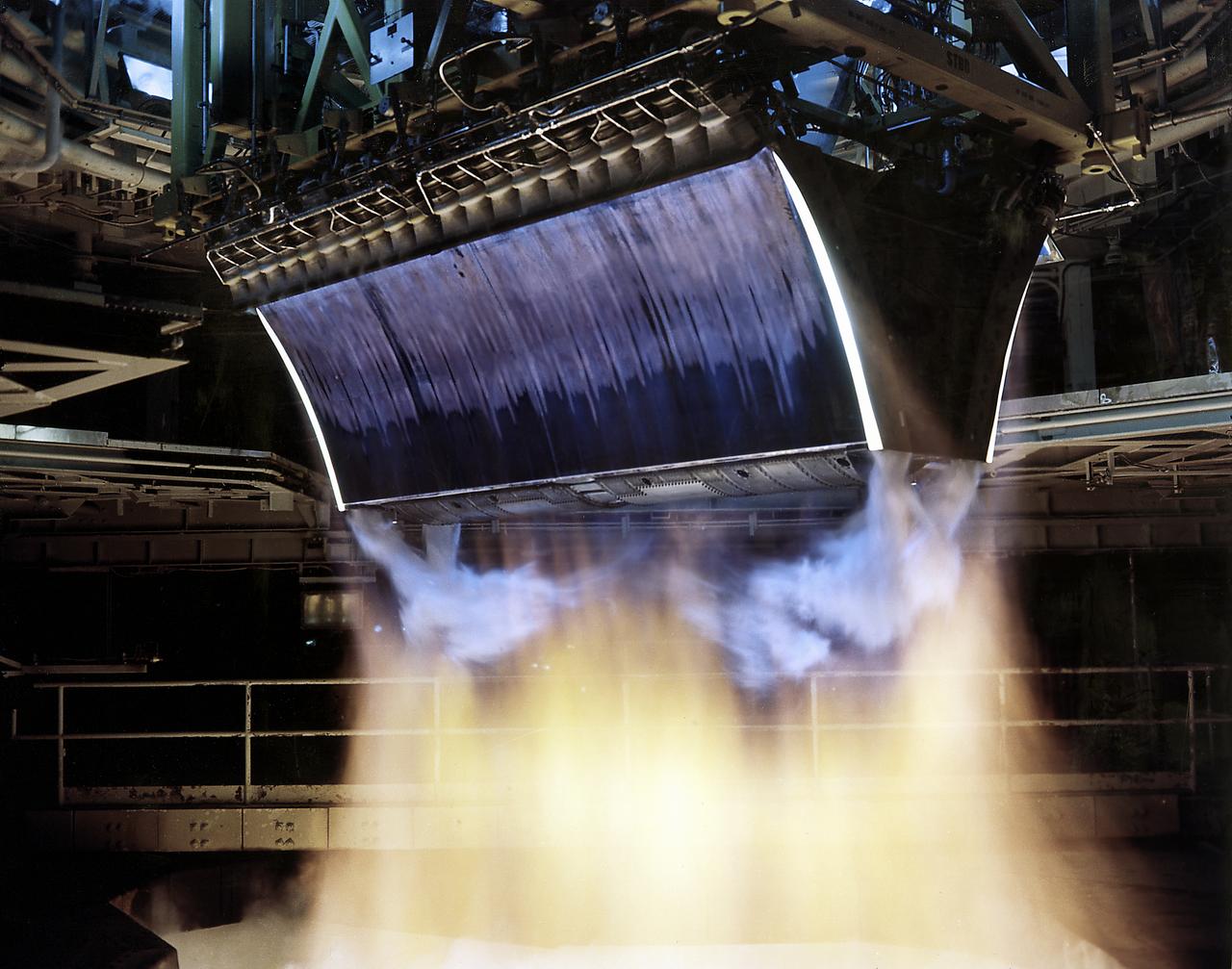
The test of twin Linear Aerospike XRS-2200 engines, originally built for the X-33 program, was performed on August 6, 2001 at NASA's Sternis Space Center, Mississippi. The engines were fired for the planned 90 seconds and reached a planned maximum power of 85 percent. NASA's Second Generation Reusable Launch Vehicle Program , also known as the Space Launch Initiative (SLI), is making advances in propulsion technology with this third and final successful engine hot fire, designed to test electro-mechanical actuators. Information learned from this hot fire test series about new electro-mechanical actuator technology, which controls the flow of propellants in rocket engines, could provide key advancements for the propulsion systems for future spacecraft. The Second Generation Reusable Launch Vehicle Program, led by NASA's Marshall Space Flight Center in Huntsville, Alabama, is a technology development program designed to increase safety and reliability while reducing costs for space travel. The X-33 program was cancelled in March 2001.
CAPE CANAVERAL, Fla. - In Orbiter Processing Facility 1 at NASA's Kennedy Space Center in Florida, United Space Alliance technicians remove the test equipment that was used to perform a push test on an external tank door on space shuttle Atlantis. Two umbilical doors, located on the shuttle's aft fuselage, close after external tank separation following launch. The test confirms that the door's actuators are functioning properly and that signals sent from the actuators correctly indicate that the doors have closed, creating the necessary thermal barrier for reentry. Atlantis is next slated to deliver an Integrated Cargo Carrier and Russian-built Mini Research Module to the International Space Station on the STS-132 mission. The second in a series of new pressurized components for Russia, the module will be permanently attached to the Zarya module. Three spacewalks are planned to store spare components outside the station, including six spare batteries, a boom assembly for the Ku-band antenna and spares for the Canadian Dextre robotic arm extension. A radiator, airlock and European robotic arm for the Russian Multi-purpose Laboratory Module also are payloads on the flight. Launch is targeted for May 14, 2010. Photo credit: NASA/Troy Cryder
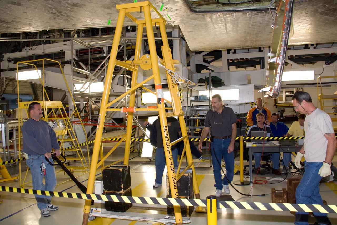
CAPE CANAVERAL, Fla. - In Orbiter Processing Facility 1 at NASA's Kennedy Space Center in Florida, United Space Alliance technicians roll the test equipment away from an external tank door on space shuttle Atlantis following the successful completion of a push test. Two umbilical doors, located on the shuttle's aft fuselage, close after external tank separation following launch. The test confirms that the door's actuators are functioning properly and that signals sent from the actuators correctly indicate that the doors have closed, creating the necessary thermal barrier for reentry. Atlantis is next slated to deliver an Integrated Cargo Carrier and Russian-built Mini Research Module to the International Space Station on the STS-132 mission. The second in a series of new pressurized components for Russia, the module will be permanently attached to the Zarya module. Three spacewalks are planned to store spare components outside the station, including six spare batteries, a boom assembly for the Ku-band antenna and spares for the Canadian Dextre robotic arm extension. A radiator, airlock and European robotic arm for the Russian Multi-purpose Laboratory Module also are payloads on the flight. Launch is targeted for May 14, 2010. Photo credit: NASA/Troy Cryder
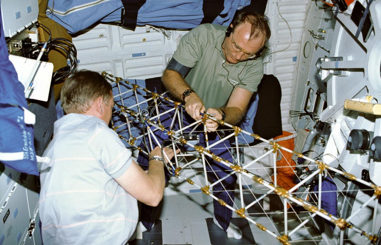
STS048-09-019 (16 Sept 1991) --- Astronauts Mark N. Brown, left, and James F. Buchli work with the structural test article (STA), a model of the space station truss structure. STA is part of the middeck zero gravity dynamics experiment (MODE). MODE was designed to study the vibration characteristics of the jointed truss structure. The structural test article includes four strain gauges and eleven accelerometers and is vibrated by an actuator. Assembled by crewmembers in the Shuttle orbiter's middeck, the device is about 72 inches long with an 8-inch square cross section.
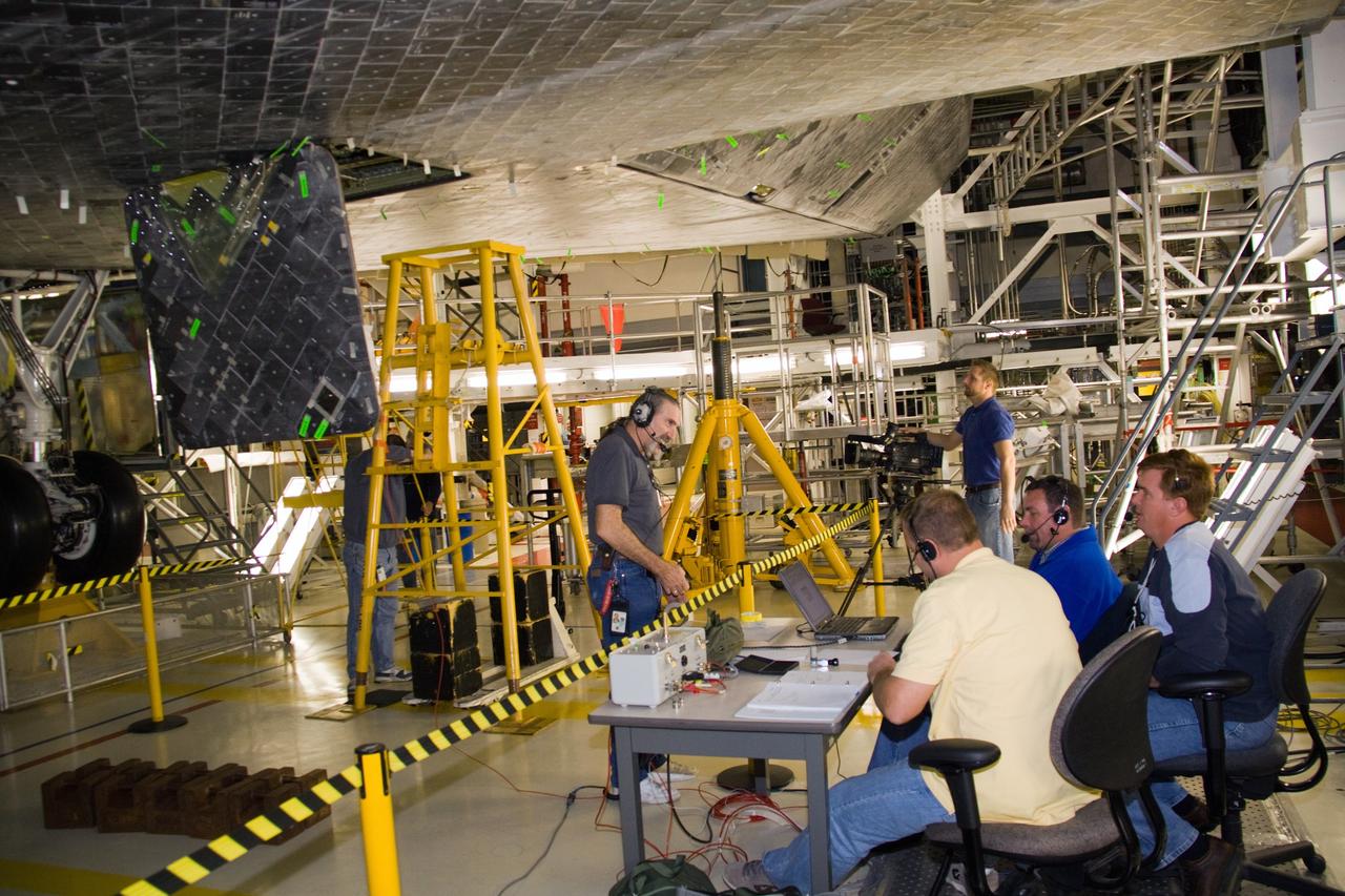
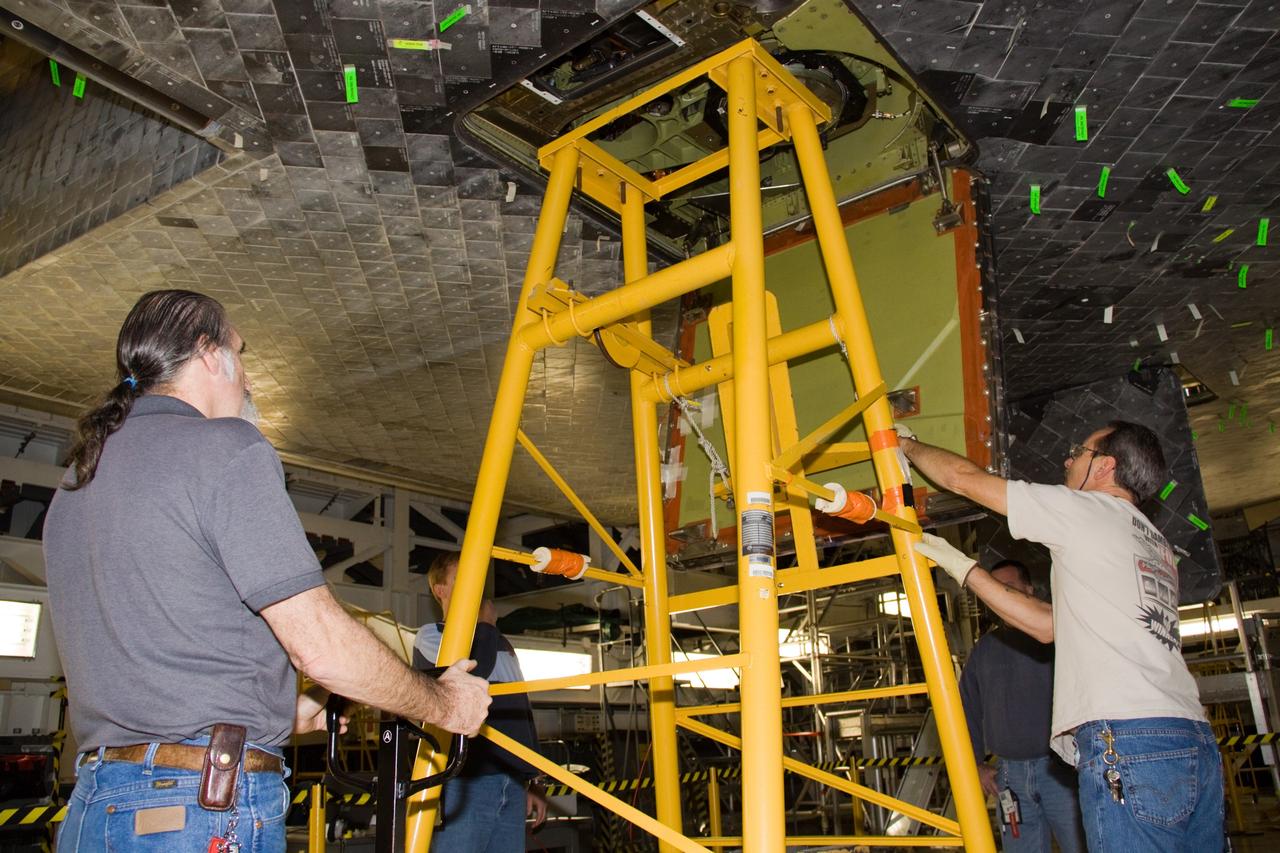
CAPE CANAVERAL, Fla. - In Orbiter Processing Facility 1 at NASA's Kennedy Space Center in Florida, United Space Alliance technicians prepare to perform a push test on an external tank door beneath space shuttle Atlantis. Two umbilical doors, located on the shuttle's aft fuselage, close after external tank separation following launch. The test confirms that the door's actuators are functioning properly and that signals sent from the actuators correctly indicate that the doors have closed, creating the necessary thermal barrier for reentry. Atlantis is next slated to deliver an Integrated Cargo Carrier and Russian-built Mini Research Module to the International Space Station on the STS-132 mission. The second in a series of new pressurized components for Russia, the module will be permanently attached to the Zarya module. Three spacewalks are planned to store spare components outside the station, including six spare batteries, a boom assembly for the Ku-band antenna and spares for the Canadian Dextre robotic arm extension. A radiator, airlock and European robotic arm for the Russian Multi-purpose Laboratory Module also are payloads on the flight. Launch is targeted for May 14, 2010. Photo credit: NASA/Troy Cryder
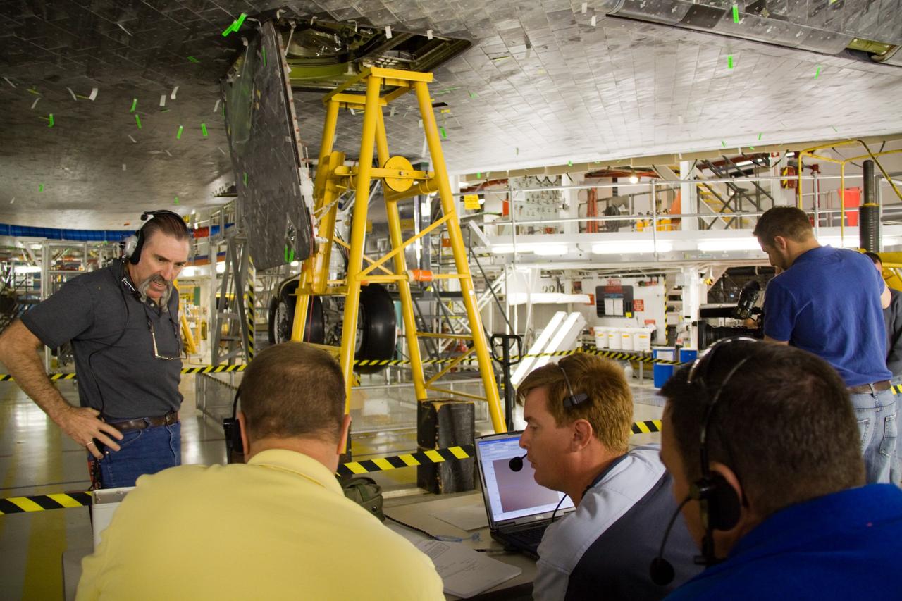
CAPE CANAVERAL, Fla. - In Orbiter Processing Facility 1 at NASA's Kennedy Space Center in Florida, United Space Alliance technicians study the results of a push test performed on an external tank door on space shuttle Atlantis. Two umbilical doors, located on the shuttle's aft fuselage, close after external tank separation following launch. The test confirms that the door's actuators are functioning properly and that signals sent from the actuators correctly indicate that the doors have closed, creating the necessary thermal barrier for reentry. Atlantis is next slated to deliver an Integrated Cargo Carrier and Russian-built Mini Research Module to the International Space Station on the STS-132 mission. The second in a series of new pressurized components for Russia, the module will be permanently attached to the Zarya module. Three spacewalks are planned to store spare components outside the station, including six spare batteries, a boom assembly for the Ku-band antenna and spares for the Canadian Dextre robotic arm extension. A radiator, airlock and European robotic arm for the Russian Multi-purpose Laboratory Module also are payloads on the flight. Launch is targeted for May 14, 2010. Photo credit: NASA/Troy Cryder

CAPE CANAVERAL, Fla. - In Orbiter Processing Facility 1 at NASA's Kennedy Space Center in Florida, preparations are under way to perform a push test on an external tank door, shown in this close-up, of space shuttle Atlantis. Two umbilical doors, located on the shuttle's aft fuselage, close after external tank separation following launch. The test confirms that the door's actuators are functioning properly and that signals sent from the actuators correctly indicate that the doors have closed, creating the necessary thermal barrier for reentry. Atlantis is next slated to deliver an Integrated Cargo Carrier and Russian-built Mini Research Module to the International Space Station on the STS-132 mission. The second in a series of new pressurized components for Russia, the module will be permanently attached to the Zarya module. Three spacewalks are planned to store spare components outside the station, including six spare batteries, a boom assembly for the Ku-band antenna and spares for the Canadian Dextre robotic arm extension. A radiator, airlock and European robotic arm for the Russian Multi-purpose Laboratory Module also are payloads on the flight. Launch is targeted for May 14, 2010. Photo credit: NASA/Troy Cryder
CAPE CANAVERAL, Fla. - In Orbiter Processing Facility 1 at NASA's Kennedy Space Center in Florida, United Space Alliance technicians perform a push test on an external tank door on space shuttle Atlantis. Two umbilical doors, located on the shuttle's aft fuselage, close after external tank separation following launch. The test confirms that the door's actuators are functioning properly and that signals sent from the actuators correctly indicate that the doors have closed, creating the necessary thermal barrier for reentry. Atlantis is next slated to deliver an Integrated Cargo Carrier and Russian-built Mini Research Module to the International Space Station on the STS-132 mission. The second in a series of new pressurized components for Russia, the module will be permanently attached to the Zarya module. Three spacewalks are planned to store spare components outside the station, including six spare batteries, a boom assembly for the Ku-band antenna and spares for the Canadian Dextre robotic arm extension. A radiator, airlock and European robotic arm for the Russian Multi-purpose Laboratory Module also are payloads on the flight. Launch is targeted for May 14, 2010. Photo credit: NASA/Troy Cryder
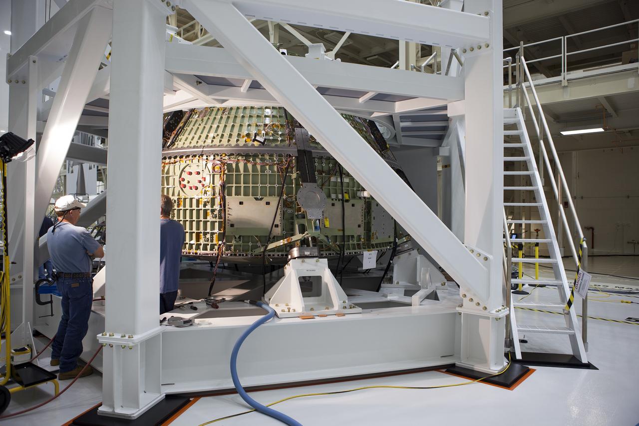
CAPE CANAVERAL, Fla. -- Inside the Operations and Checkout Building high bay at NASA’s Kennedy Space Center in Florida, technicians place a hydraulic actuator in the test stand for the Orion crew module. Lockheed Martin Space Systems and NASA engineers are preparing Orion for a series of static load tests that simulate the massive loads the spacecraft would experience during its mission. Orion is the exploration spacecraft designed to carry crews to space beyond low Earth orbit. It will provide emergency abort capability, sustain the crew during the space travel and provide safe re-entry from deep space return velocities. Orion’s first unpiloted test flight, Exploration Flight Test 1, is scheduled to launch in 2014 atop a Delta IV rocket. A second uncrewed flight test is scheduled for 2017 on NASA’s Space Launch System rocket. For more information, visit http://www.nasa.gov/orion. Photo credit: NASA/Gary Thompson

Outlined with gold stripes are the hinged nose strakes, modifications made to NASA's F-18 HARV (High Alpha Research Vehicle) at the Dryden Flight Research Center, Edwards, California. Actuated Nose Strakes for Enhanced Rolling (ANSER) were installed to fly the third and final phase in the HARV flight test project. Normally folded flush, the units -- four feet long and six inches wide -- can be opened independently to interact with the nose vortices to produce large side forces for control. Early wind tunnel tests indicated that the strakes would be as effective in yaw control at high angles of attack as rudders are at lower angles. Testing involved evaluation of the strakes by themselves as well as combined with the aircraft's Thrust Vectoring System. The strakes were designed by NASA's Langley Research Center, then installed and flight tested at Dryden.
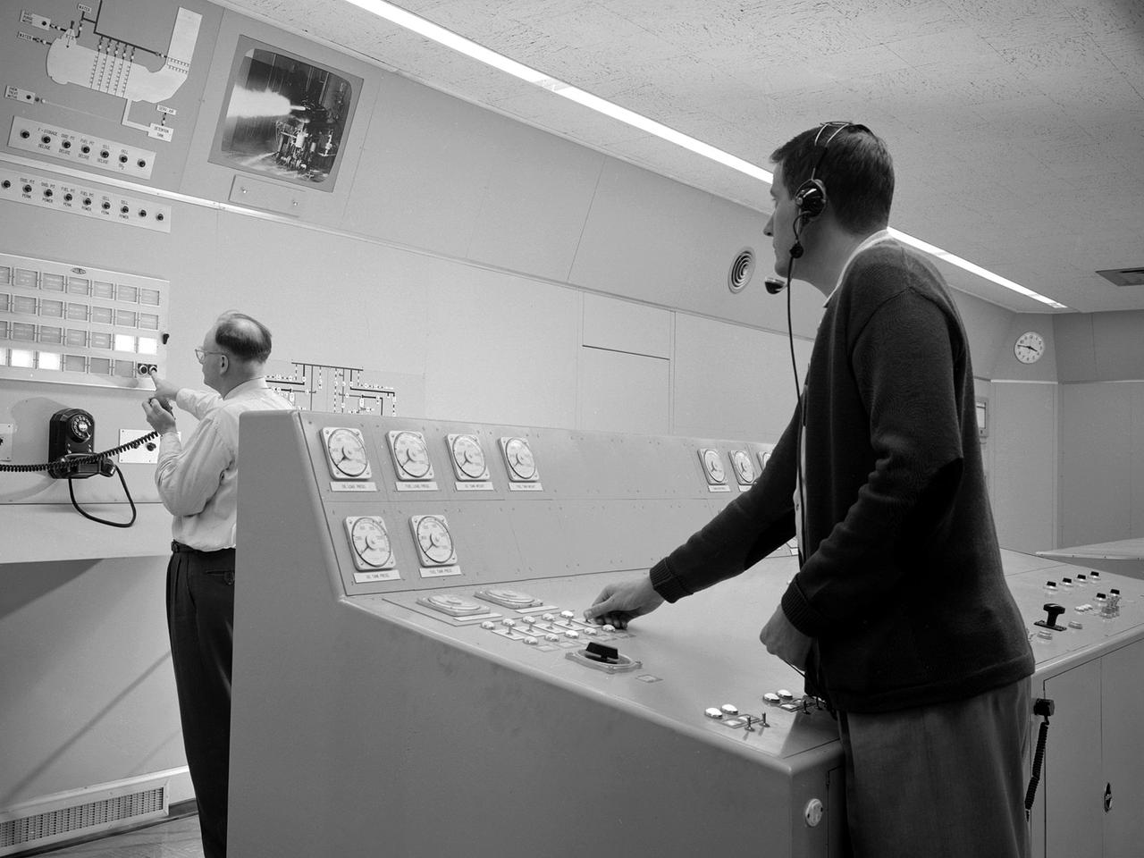
Test engineers monitor an engine firing from the control room of the Rocket Engine Test Facility at the National Advisory Committee for Aeronautics (NACA) Lewis Flight Propulsion Laboratory. The Rocket Engine Test Facility, built in the early 1950s, had a rocket stand designed to evaluate high-energy propellants and rocket engine designs. The facility was used to study numerous different types of rocket engines including the Pratt and Whitney RL-10 engine for the Centaur rocket and Rocketdyne’s F-1 and J-2 engines for the Saturn rockets. The Rocket Engine Test Facility was built in a ravine at the far end of the laboratory because of its use of the dangerous propellants such as liquid hydrogen and liquid fluorine. The control room was located in a building 1,600 feet north of the test stand to protect the engineers running the tests. The main control and instrument consoles were centrally located in the control room and surrounded by boards controlling and monitoring the major valves, pumps, motors, and actuators. A camera system at the test stand allowed the operators to view the tests, but the researchers were reliant on data recording equipment, sensors, and other devices to provide test data. The facility’s control room was upgraded several times over the years. Programmable logic controllers replaced the electro-mechanical control devices. The new controllers were programed to operate the valves and actuators controlling the fuel, oxidant, and ignition sequence according to a predetermined time schedule.

Members of JPL's assembly, test and launch operations team for NASA's Perseverance mission show appreciation for their newly named rover. The image was taken on March 4, 2020, at a payload processing facility at NASA's Kennedy Space Center. The plate is actually a rock and debris shield, designed to protect a cable that carries power and data from computers in the rover's body to actuators in the arm, as well as to the rotary percussive drill and instruments in the turret. Weighing in at about 104 grams (3.7 ounces), the 17-inch-long by 3.25-inch-wide (43-centimeter-long by 8.26-centimeter-wide) plate was cut using a water jet. The surface was coated with black thermal paint before a computer-guided laser generated the name "Perseverance" by ablating paint off the surface. The nameplate was attached to the rover on March 4, 2020. https://photojournal.jpl.nasa.gov/catalog/PIA23767

A Mercury capsule is mounted inside the Altitude Wind Tunnel for a test of its escape tower rockets at the National Aeronautics and Space Administration (NASA) Lewis Research Center. In October 1959 NASA’s Space Task Group allocated several Project Mercury assignments to Lewis. The Altitude Wind Tunnel was quickly modified so that its 51-foot diameter western leg could be used as a test chamber. The final round of tests in the Altitude Wind Tunnel sought to determine if the smoke plume from the capsule’s escape tower rockets would shroud or compromise the spacecraft. The escape tower, a 10-foot steel rig with three small rockets, was attached to the nose of the Mercury capsule. It could be used to jettison the astronaut and capsule to safety in the event of a launch vehicle malfunction on the pad or at any point prior to separation from the booster. Once actuated, the escape rockets would fire, and the capsule would be ejected away from the booster. After the capsule reached its apex of about 2,500 feet, the tower, heatshield, retropackage, and antenna would be ejected and a drogue parachute would be released. Flight tests of the escape system were performed at Wallops Island as part of the series of Little Joe launches. Although the escape rockets fired prematurely on Little Joe’s first attempt in August 1959, the January 1960 follow-up was successful.

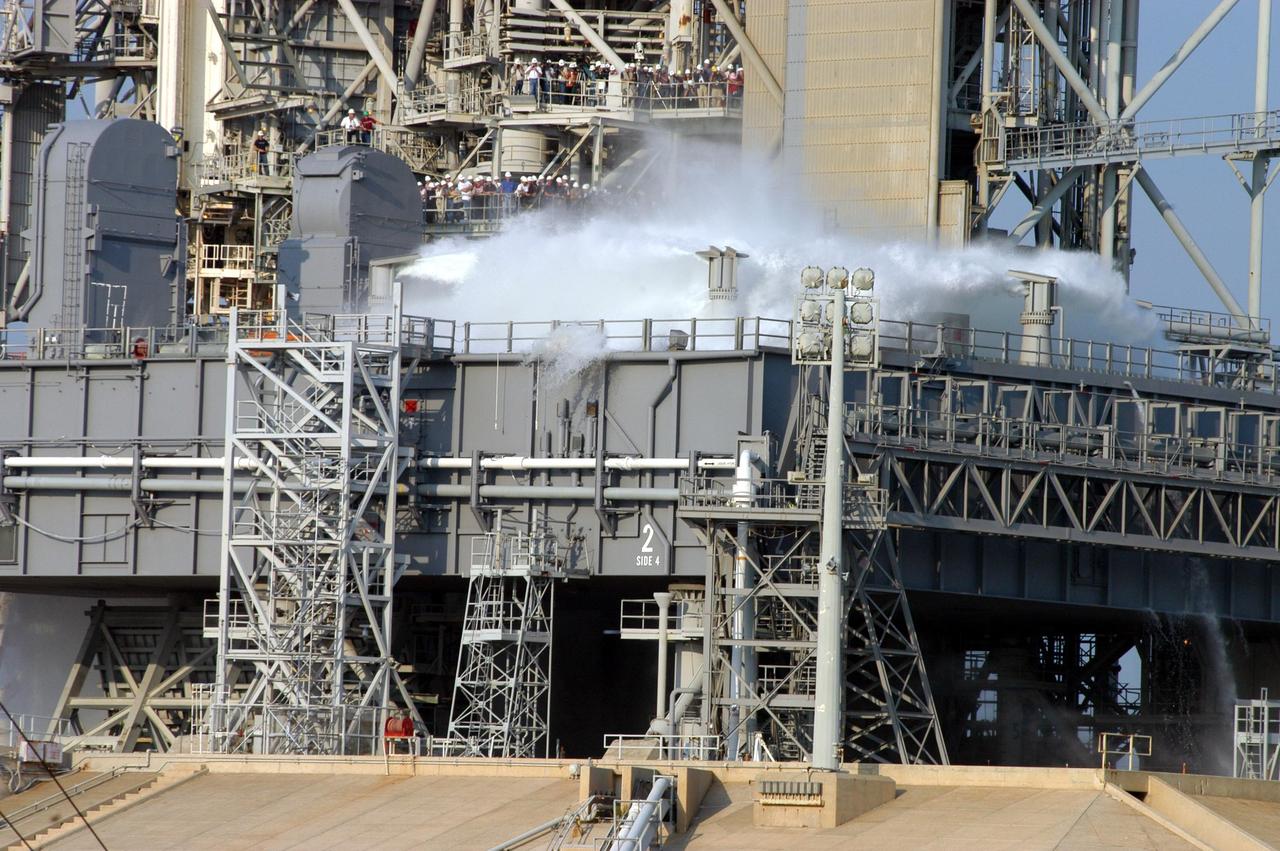
KENNEDY SPACE CENTER, FLA. -- For the fourth time in Space Shuttle Program history, 350,000 gallons of water are released on a Mobile Launcher Platform (MLP) at Launch Pad 39A during a water sound suppression test. This test is being conducted following the replacement of the six main system valves, which had been in place since the beginning of the Shuttle Program and had reached the end of their service life. Also, the hydraulic portion of the valve actuators has been redesigned and simplified to reduce maintenance costs. The sound suppression water system is installed on the launch pads to protect the orbiter and its payloads from damage by acoustical energy reflected from the MLP during launch. The system includes an elevated water tank with a capacity of 300,000 gallons. The tank is 290 feet high and stands on the northeast side of the Pad. The water is released just before the ignition of the orbiter's three main engines and twin solid rocket boosters, and flows through parallel 7-foot-diameter pipes to the Pad area.

KENNEDY SPACE CENTER, FLA. -- Water recedes from the Mobile Launcher Platform (MLP) on Launch Pad 39A after the water sound suppression test. Workers and the media (left) were on hand to witness the rare event. This test was conducted following the replacement of the six main system valves, which had been in place since the beginning of the Shuttle Program and had reached the end of their service life. Also, the hydraulic portion of the valve actuators has been redesigned and simplified to reduce maintenance costs. The sound suppression water system is installed on the launch pads to protect the orbiter and its payloads from damage by acoustical energy reflected from the MLP during launch. The system includes an elevated water tank with a capacity of 300,000 gallons. The tank is 290 feet high and stands on the northeast side of the Pad. The water is released just before the ignition of the orbiter's three main engines and twin solid rocket boosters, and flows through parallel 7-foot-diameter pipes to the Pad area.

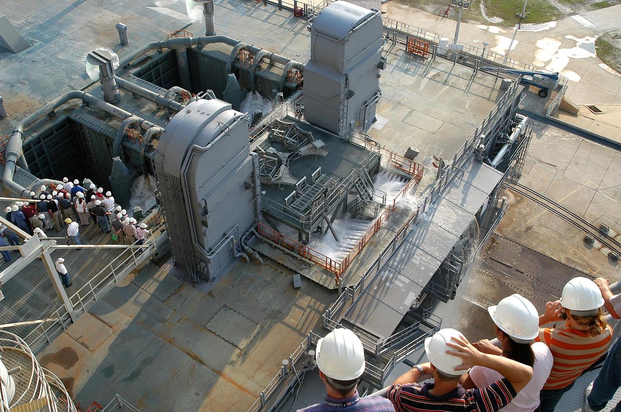
KENNEDY SPACE CENTER, FLA. -- For the fourth time in Space Shuttle Program history, 350,000 gallons of water are being released on a Mobile Launcher Platform (MLP) at Launch Pad 39A during a water sound suppression test. Because of the unusual event, media and workers watch from nearby vantage points on the Fixed Service Structure (left). This test is being conducted following the replacement of the six main system valves, which had been in place since the beginning of the Shuttle Program and had reached the end of their service life. Also, the hydraulic portion of the valve actuators has been redesigned and simplified to reduce maintenance costs. The sound suppression water system is installed on the launch pads to protect the orbiter and its payloads from damage by acoustical energy reflected from the MLP during launch. The system includes an elevated water tank with a capacity of 300,000 gallons. The tank is 290 feet high and stands on the northeast side of the Pad. The water is released just before the ignition of the orbiter's three main engines and twin solid rocket boosters, and flows through parallel 7-foot-diameter pipes to the Pad area.

KENNEDY SPACE CENTER, FLA. -- For the fourth time in Space Shuttle Program history, 350,000 gallons of water are being released on a Mobile Launcher Platform (MLP) at Launch Pad 39A during a water sound suppression test. Because of the unusual event, media and workers watch from nearby vantage points on the Fixed Service Structure (left). This test is being conducted following the replacement of the six main system valves, which had been in place since the beginning of the Shuttle Program and had reached the end of their service life. Also, the hydraulic portion of the valve actuators has been redesigned and simplified to reduce maintenance costs. The sound suppression water system is installed on the launch pads to protect the orbiter and its payloads from damage by acoustical energy reflected from the MLP during launch. The system includes an elevated water tank with a capacity of 300,000 gallons. The tank is 290 feet high and stands on the northeast side of the Pad. The water is released just before the ignition of the orbiter's three main engines and twin solid rocket boosters, and flows through parallel 7-foot-diameter pipes to the Pad area.
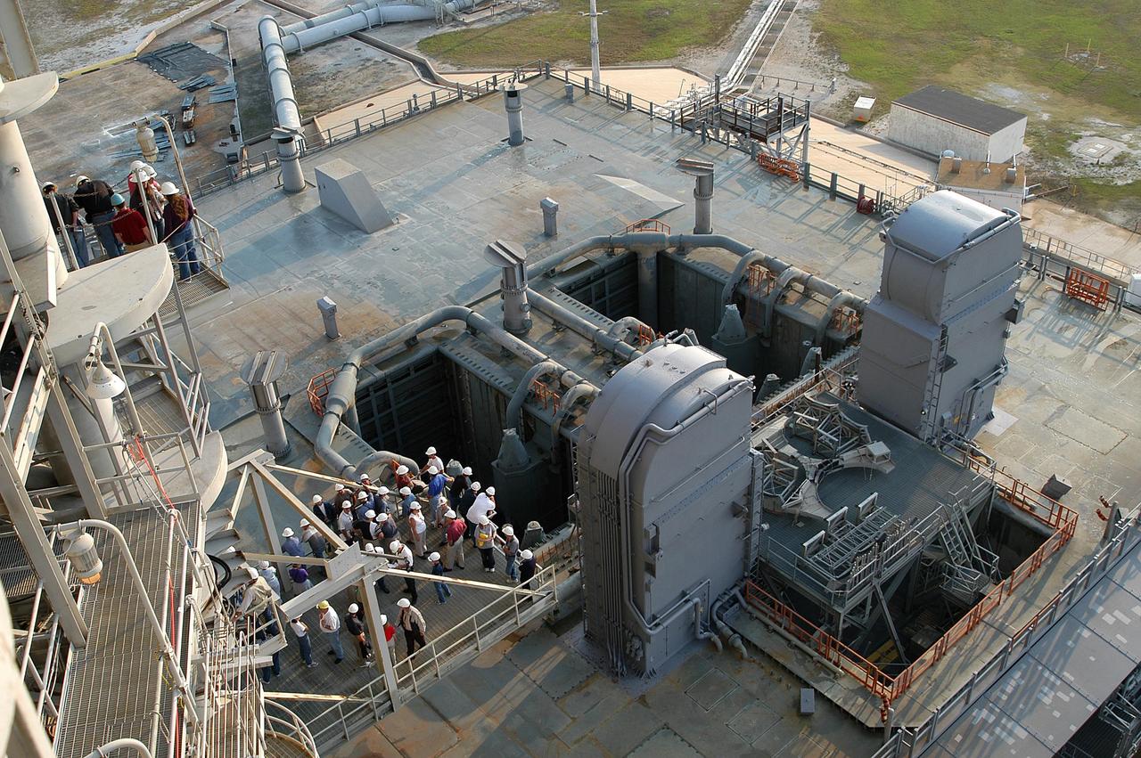
KENNEDY SPACE CENTER, FLA. -- From vantage points on the Fixed Service Structure (left) on Launch Pad 39A, workers and the media look down upon the Mobile Launcher Platform (MLP) waiting for the start of a water sound suppression test. This test is being conducted following the replacement of the six main system valves, which had been in place since the beginning of the Shuttle Program and had reached the end of their service life. Also, the hydraulic portion of the valve actuators has been redesigned and simplified to reduce maintenance costs. The sound suppression water system is installed on the launch pads to protect the orbiter and its payloads from damage by acoustical energy reflected from the MLP during launch. The system includes an elevated water tank with a capacity of 300,000 gallons. The tank is 290 feet high and stands on the northeast side of the Pad. The water is released just before the ignition of the orbiter's three main engines and twin solid rocket boosters, and flows through parallel 7-foot-diameter pipes to the Pad area.

KENNEDY SPACE CENTER, FLA. -- For the fourth time in Space Shuttle Program history, 350,000 gallons of water are released on a Mobile Launcher Platform (MLP) at Launch Pad 39A during a water sound suppression test. This test is being conducted following the replacement of the six main system valves, which had been in place since the beginning of the Shuttle Program and had reached the end of their service life. Also, the hydraulic portion of the valve actuators has been redesigned and simplified to reduce maintenance costs. The sound suppression water system is installed on the launch pads to protect the orbiter and its payloads from damage by acoustical energy reflected from the MLP during launch. The system includes an elevated water tank with a capacity of 300,000 gallons. The tank is 290 feet high and stands on the northeast side of the Pad. The water is released just before the ignition of the orbiter's three main engines and twin solid rocket boosters, and flows through parallel 7-foot-diameter pipes to the Pad area.

KENNEDY SPACE CENTER, FLA. -- Water is released onto the Mobile Launcher Platform (MLP) on Launch Pad 39A at the start of a water sound suppression test. Workers and the media (left) are on hand to witness the rare event. This test is being conducted following the replacement of the six main system valves, which had been in place since the beginning of the Shuttle Program and had reached the end of their service life. Also, the hydraulic portion of the valve actuators has been redesigned and simplified to reduce maintenance costs. The sound suppression water system is installed on the launch pads to protect the orbiter and its payloads from damage by acoustical energy reflected from the MLP during launch. The system includes an elevated water tank with a capacity of 300,000 gallons. The tank is 290 feet high and stands on the northeast side of the Pad. The water is released just before the ignition of the orbiter's three main engines and twin solid rocket boosters, and flows through parallel 7-foot-diameter pipes to the Pad area.

KENNEDY SPACE CENTER, FLA. -- Water is released onto the Mobile Launcher Platform (MLP) on Launch Pad 39A at the start of a water sound suppression test. Workers and the media (left) are on hand to witness the rare event. This test is being conducted following the replacement of the six main system valves, which had been in place since the beginning of the Shuttle Program and had reached the end of their service life. Also, the hydraulic portion of the valve actuators has been redesigned and simplified to reduce maintenance costs. The sound suppression water system is installed on the launch pads to protect the orbiter and its payloads from damage by acoustical energy reflected from the MLP during launch. The system includes an elevated water tank with a capacity of 300,000 gallons. The tank is 290 feet high and stands on the northeast side of the Pad. The water is released just before the ignition of the orbiter's three main engines and twin solid rocket boosters, and flows through parallel 7-foot-diameter pipes to the Pad area.

KENNEDY SPACE CENTER, FLA. -- For the fourth time in Space Shuttle Program history, 350,000 gallons of water are released on a Mobile Launcher Platform (MLP) at Launch Pad 39A during a water sound suppression test. Because of the unusual event, media and workers watch from nearby vantage points on the Fixed Service Structure (left). This test is being conducted following the replacement of the six main system valves, which had been in place since the beginning of the Shuttle Program and had reached the end of their service life. Also, the hydraulic portion of the valve actuators has been redesigned and simplified to reduce maintenance costs. The sound suppression water system is installed on the launch pads to protect the orbiter and its payloads from damage by acoustical energy reflected from the MLP during launch. The system includes an elevated water tank with a capacity of 300,000 gallons. The tank is 290 feet high and stands on the northeast side of the Pad. The water is released for launch just before the ignition of the orbiter's three main engines and twin solid rocket boosters, and flows through parallel 7-foot-diameter pipes to the Pad area.
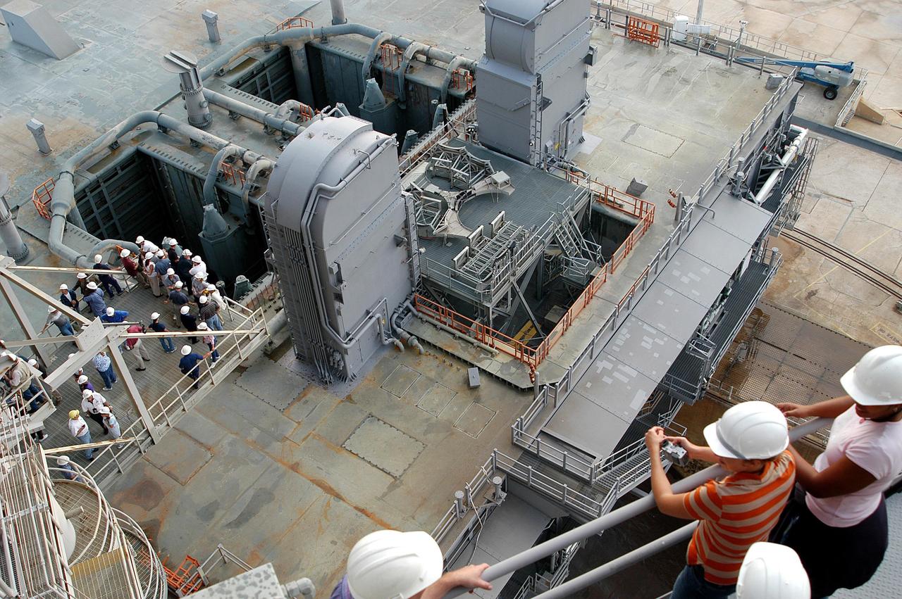
KENNEDY SPACE CENTER, FLA. -- From vantage points on the Fixed Service Structure (left) on Launch Pad 39A, workers and the media look down upon the Mobile Launcher Platform (MLP) waiting for the start of a water sound suppression test. This test is being conducted following the replacement of the six main system valves, which had been in place since the beginning of the Shuttle Program and had reached the end of their service life. Also, the hydraulic portion of the valve actuators has been redesigned and simplified to reduce maintenance costs. The sound suppression water system is installed on the launch pads to protect the orbiter and its payloads from damage by acoustical energy reflected from the MLP during launch. The system includes an elevated water tank with a capacity of 300,000 gallons. The tank is 290 feet high and stands on the northeast side of the Pad. The water is released just before the ignition of the orbiter's three main engines and twin solid rocket boosters, and flows through parallel 7-foot-diameter pipes to the Pad area.

KENNEDY SPACE CENTER, FLA. -- For the fourth time in Space Shuttle Program history, 350,000 gallons of water are being released on a Mobile Launcher Platform (MLP) at Launch Pad 39A during a water sound suppression test. Because of the unusual event, media and workers watch from nearby vantage points on the Fixed Service Structure (left). This test is being conducted following the replacement of the six main system valves, which had been in place since the beginning of the Shuttle Program and had reached the end of their service life. Also, the hydraulic portion of the valve actuators has been redesigned and simplified to reduce maintenance costs. The sound suppression water system is installed on the launch pads to protect the orbiter and its payloads from damage by acoustical energy reflected from the MLP during launch. The system includes an elevated water tank with a capacity of 300,000 gallons. The tank is 290 feet high and stands on the northeast side of the Pad. The water is released just before the ignition of the orbiter's three main engines and twin solid rocket boosters, and flows through parallel 7-foot-diameter pipes to the Pad area.

KENNEDY SPACE CENTER, FLA. -- A crimson and gold sunrise over the Central Florida coast begins illuminating Launch Pad 39A, where a water sound suppression test is to take place. This test is being conducted following the replacement of the six main system valves, which had been in place since the beginning of the Shuttle Program and had reached the end of their service life. Also, the hydraulic portion of the valve actuators has been redesigned and simplified to reduce maintenance costs. The sound suppression water system is installed on the launch pads to protect the orbiter and its payloads from damage by acoustical energy reflected from the MLP during launch. The system includes an elevated water tank with a capacity of 300,000 gallons. The tank is 290 feet high and stands on the northeast side of the Pad. The water is released just before the ignition of the orbiter’s three main engines and twin solid rocket boosters, and flows through parallel 7-foot-diameter pipes to the Pad area.
KENNEDY SPACE CENTER, FLA. -- From vantage points on the Fixed Service Structure (bottom right and left) on Launch Pad 39A, workers and the media look down upon the Mobile Launcher Platform (MLP) at the start of a water sound suppression test. This test is being conducted following the replacement of the six main system valves, which had been in place since the beginning of the Shuttle Program and had reached the end of their service life. Also, the hydraulic portion of the valve actuators has been redesigned and simplified to reduce maintenance costs. The sound suppression water system is installed on the launch pads to protect the orbiter and its payloads from damage by acoustical energy reflected from the MLP during launch. The system includes an elevated water tank with a capacity of 300,000 gallons. The tank is 290 feet high and stands on the northeast side of the Pad. The water is released just before the ignition of the orbiter's three main engines and twin solid rocket boosters, and flows through parallel 7-foot-diameter pipes to the Pad area.
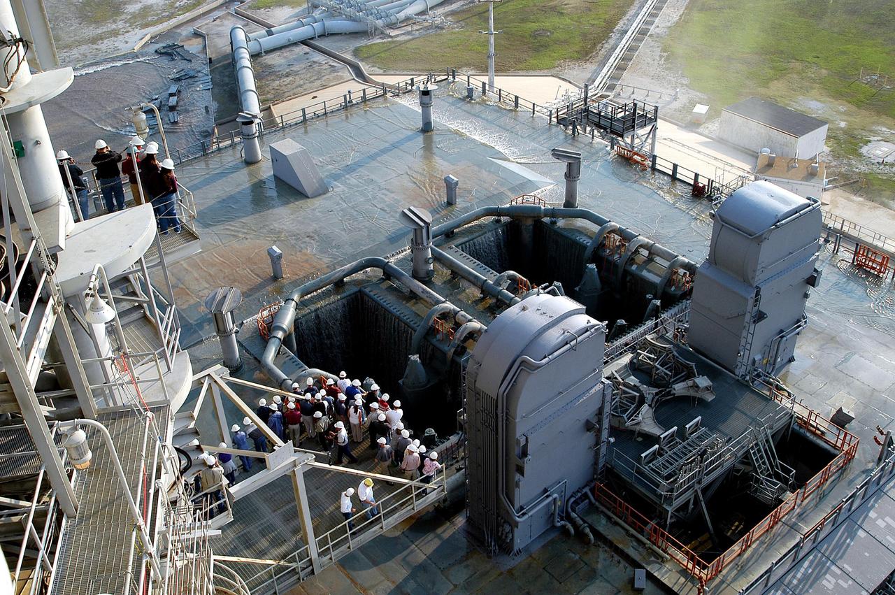
KENNEDY SPACE CENTER, FLA. -- Some water remains on the surface of the Mobile Launcher Platform (MLP) on Launch Pad 39A after a water sound suppression test. Workers and the media (left) were on hand to witness the rare event. This test was conducted following the replacement of the six main system valves, which had been in place since the beginning of the Shuttle Program and had reached the end of their service life. Also, the hydraulic portion of the valve actuators has been redesigned and simplified to reduce maintenance costs. The sound suppression water system is installed on the launch pads to protect the orbiter and its payloads from damage by acoustical energy reflected from the MLP during launch. The system includes an elevated water tank with a capacity of 300,000 gallons. The tank is 290 feet high and stands on the northeast side of the Pad. The water is released just before the ignition of the orbiter's three main engines and twin solid rocket boosters, and flows through parallel 7-foot-diameter pipes to the Pad area.

KENNEDY SPACE CENTER, FLA. -- For the fourth time in Space Shuttle Program history, 350,000 gallons of water are released on a Mobile Launcher Platform (MLP) at Launch Pad 39A during a water sound suppression test. This test is being conducted following the replacement of the six main system valves, which had been in place since the beginning of the Shuttle Program and had reached the end of their service life. Also, the hydraulic portion of the valve actuators has been redesigned and simplified to reduce maintenance costs. The sound suppression water system is installed on the launch pads to protect the orbiter and its payloads from damage by acoustical energy reflected from the MLP during launch. The system includes an elevated water tank with a capacity of 300,000 gallons. The tank is 290 feet high and stands on the northeast side of the Pad. The water is released just before the ignition of the orbiter's three main engines and twin solid rocket boosters, and flows through parallel 7-foot-diameter pipes to the Pad area.
KENNEDY SPACE CENTER, FLA. -- For the fourth time in Space Shuttle Program history, 350,000 gallons of water are released on a Mobile Launcher Platform (MLP) at Launch Pad 39A during a water sound suppression test. This test is being conducted following the replacement of the six main system valves, which had been in place since the beginning of the Shuttle Program and had reached the end of their service life. Also, the hydraulic portion of the valve actuators has been redesigned and simplified to reduce maintenance costs. The sound suppression water system is installed on the launch pads to protect the orbiter and its payloads from damage by acoustical energy reflected from the MLP during launch. The system includes an elevated water tank with a capacity of 300,000 gallons. The tank is 290 feet high and stands on the northeast side of the Pad. The water is released just before the ignition of the orbiter's three main engines and twin solid rocket boosters, and flows through parallel 7-foot-diameter pipes to the Pad area.
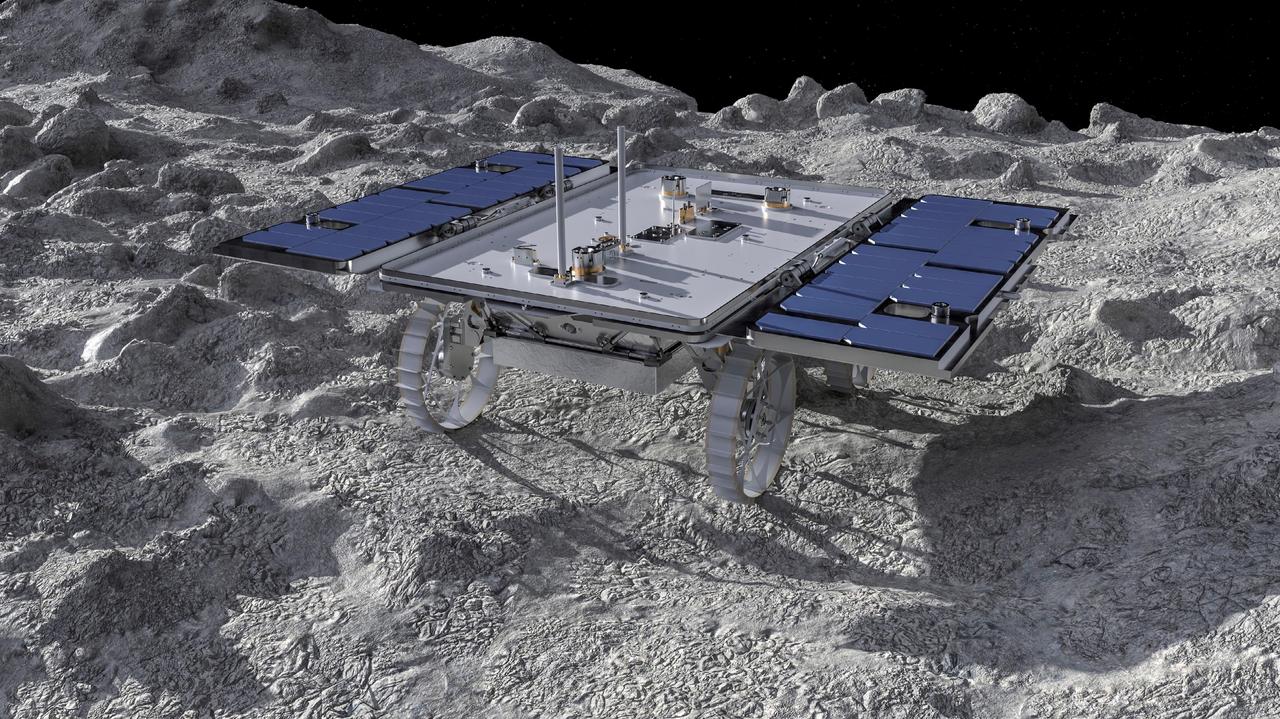
This artist's concept depicts a small rover – part of NASA's CADRE (Cooperative Autonomous Distributed Robotic Exploration) technology demonstration headed for the Moon – on the lunar surface. Motiv Space Systems in Pasadena, California, created the rendering and is collaborating with NASA's Jet Propulsion Laboratory on critical rover and mobility functions. Slated to arrive aboard a lunar lander in 2024 under NASA's CLPS (Commercial Lunar Payload Services) initiative, CADRE is designed to demonstrate that multiple robots can cooperate and explore together autonomously – without direct input from human mission controllers. A trio of the miniature solar-powered rovers, each about the size of a carry-on suitcase, will explore the Moon as a team, communicating via radio with each other and a base station aboard a lunar lander. By taking simultaneous measurements from multiple locations, CADRE will also demonstrate how multirobot missions can record data impossible for a single robot to achieve – a tantalizing prospect for future missions. Motiv contributed subsystems and hardware elements for three of four CADRE systems, including designing and building the mobility system and rover chassis, the base station, the rover deployers, and the motor controller boards. The company also procured and tested the actuators with the flight motor controller boards. https://photojournal.jpl.nasa.gov/catalog/PIA26161
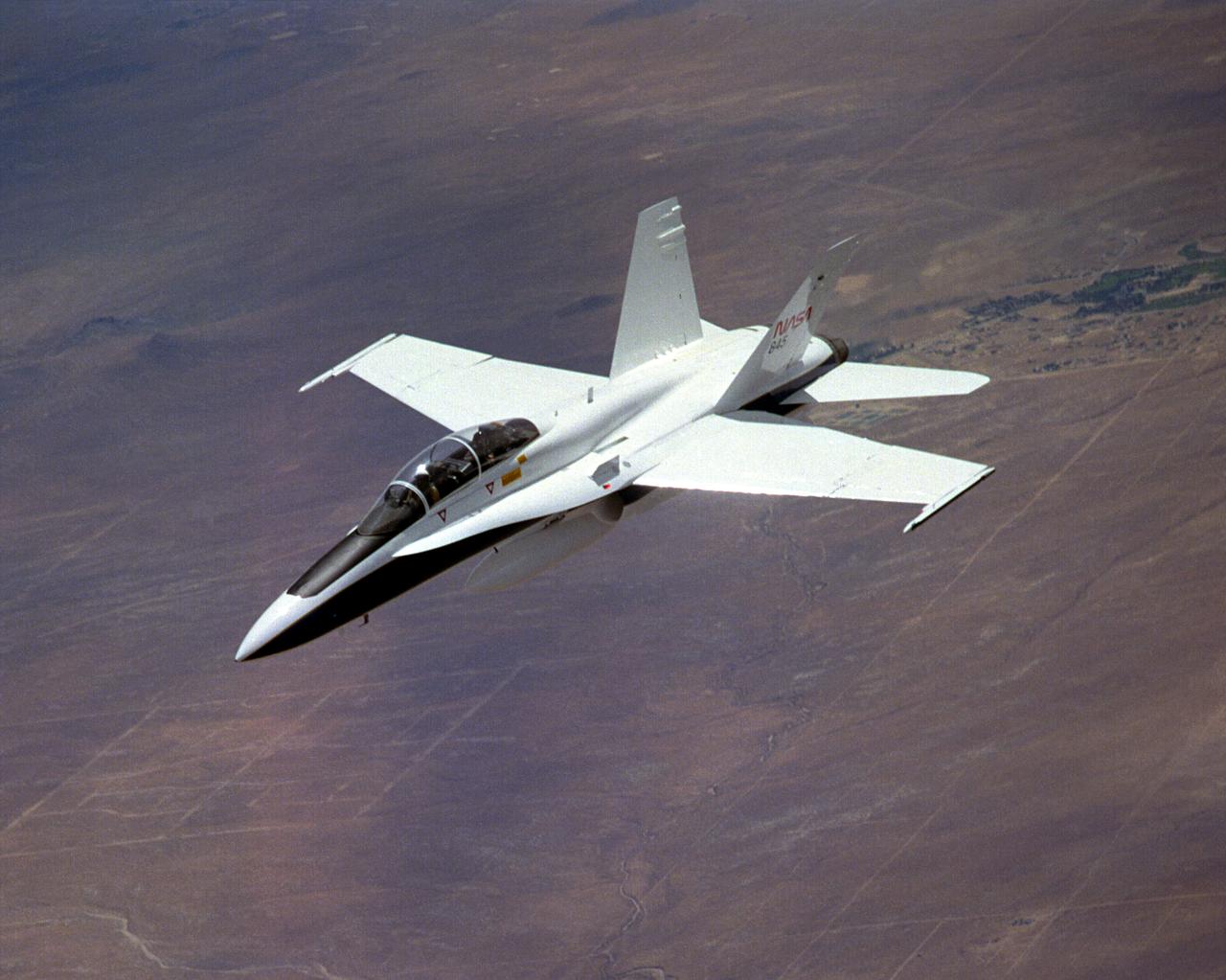
The National Aeronautics and Space Administration's Systems Research Aircraft (SRA), a highly modified F-18 jet fighter, during a research flight. The former Navy aircraft was flown by NASA's Dryden Flight Research Center at Edwards Air Force Base, California, to evaluate a number of experimental aerospace technologies in a multi-year, joint NASA/DOD/industry program. Among the more than 20 experiments flight-tested were several involving fiber optic sensor systems. Experiments developed by McDonnell-Douglas and Lockheed-Martin centered on installation and maintenace techniques for various types of fiber-optic hardware proposed for use in military and commercial aircraft, while a Parker-Hannifin experiment focused in alternative fiber-optic designs for position measurement sensors as well as operational experience in handling optical sensor systems. Other experiments flown on this testbed aircraft included electronically-controlled control surface actuators, flush air data collection systems, "smart" skin antennae and laser-based systems. Incorporation of one or more of these technologies in future aircraft and spacecraft could result in signifigant savings in weight, maintenance and overall cost.
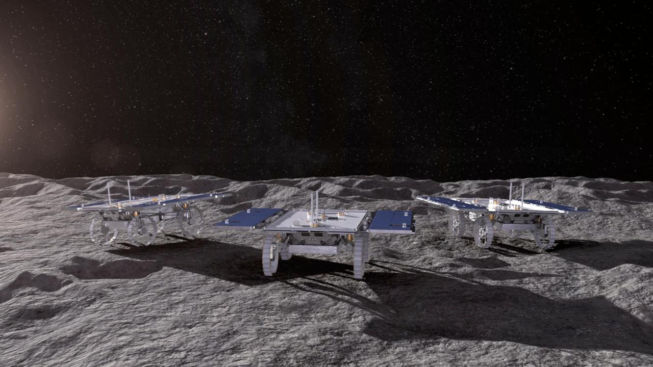
This animated artist's concept depicts three small rovers – part of NASA's CADRE (Cooperative Autonomous Distributed Robotic Exploration) technology demonstration headed for the Moon – driving together on the lunar surface. Motiv Space Systems in Pasadena, California, created the rendering and collaborated with NASA's Jet Propulsion Laboratory on critical rover and mobility functions. Slated to arrive aboard a lunar lander at the Reiner Gamma region of the Moon under NASA's CLPS (Commercial Lunar Payload Services) initiative, CADRE is designed to demonstrate that multiple robots can cooperate and explore together autonomously – without direct input from human mission controllers. A trio of the miniature solar-powered rovers, each about the size of a carry-on suitcase, will explore the Moon as a team, communicating via radio with each other and a base station aboard the lander. By taking simultaneous measurements from multiple locations, CADRE will also demonstrate how multirobot missions can record data impossible for a single robot to achieve – a tantalizing prospect for future missions. Motiv contributed subsystems and hardware elements for three of four CADRE systems, including designing and building the mobility system and rover chassis, the base station, the rover deployers, and the motor controller boards. The company also procured and tested the actuators with the flight motor controller boards. Animation available at https://photojournal.jpl.nasa.gov/catalog/PIA26296
The National Aeronautics and Space Administration's Systems Research Aircraft (SRA), a highly modified F-18 jet fighter, on an early research flight over Rogers Dry Lake. The former Navy aircraft was flown by NASA's Dryden Flight Research Center at Edwards Air Force Base, California, to evaluate a number of experimental aerospace technologies in a multi-year, joint NASA/DOD/industry program. Among the more than 20 experiments flight-tested were several involving fiber optic sensor systems. Experiments developed by McDonnell-Douglas and Lockheed-Martin centered on installation and maintenace techniques for various types of fiber-optic hardware proposed for use in military and commercial aircraft, while a Parker-Hannifin experiment focused on alternative fiber-optic designs for postion measurement sensors as well as operational experience in handling optical sensor systems. Other experiments flown on this testbed aircraft included electronically-controlled control surface actuators, flush air data collection systems, "smart" skin antennae and laser-based systems. Incorporation of one or more of these technologies in future aircraft and spacecraft could result in signifigant savings in weight, maintenance and overall cost.
In early 2022, the Cold Operable Lunar Deployable Arm (COLDArm) project – led by NASA's Jet Propulsion Laboratory in Southern California – successfully integrated special gears into pieces of a robotic arm that is planned to perform a robot-controlled lunar surface experiment with imagery in the coming years. These bulk metallic glass (BMG) gears, integrated into COLDArm's joints and actuators, were developed through the Game Changing Development bulk metallic glass gears project to operate at extreme temperatures below minus 280 degrees Fahrenheit (minus 173 degrees Celsius). The gear alloys have a disordered atomic-scale structure, making them both strong and elastic enough to withstand these exceptionally low temperatures. Typical gearboxes require heating to operate at such cryogenic temperatures. The BMG gear motors have been tested and successfully operated at roughly minus 279 degrees Fahrenheit (minus 173 degrees Celsius) without heating assistance. This gear motor is one of the key technologies to enable the robotic arm to operate in extremely cold environments, such as during lunar night. Each of the four joints containing BMG gears will be tested once the arm is fully assembled, which is scheduled for spring of 2022. Robotic joint testing will include dynamometer testing to measure torque/rotational speed, as well as cryogenic thermal vacuum testing to understand how the equipment would perform in an environment similar to space. Once proven, the BMG gears and COLDArm capabilities will enable future missions to work in extreme environments on the Moon, Mars, and ocean worlds. https://photojournal.jpl.nasa.gov/catalog/PIA24567
The Solar Electric Propulsion (SEP) Chassis of NASA's Psyche spacecraft is mounted onto a rotation fixture in High Bay 1 of the Spacecraft Assembly Facility at NASA's Jet Propulsion Laboratory in Southern California. This photo was taken March 28, 2021, just after the chassis — a major component of the Psyche spacecraft — was delivered to JPL by Maxar Technologies. Maxar's team in Palo Alto, California, designed and built the chassis, which includes all the primary and secondary structure and the hardware components needed for the high-power electrical system, the propulsion system, the thermal system, guidance and navigation sensors and actuators, and the high-gain antenna. The phase known as assembly test, and launch operations (ATLO) for Psyche is now underway at JPL. In this photo, ATLO Mechanical Lead Michelle Colizzi of JPL oversees the docking of the chassis to the dolly. Over the next year additional hardware will be added to the spacecraft including the command and data handling system, a power distribution assembly, the X-band telecommunications hardware suite, three science instruments (two imagers, two magnetometers, and a Gamma Ray Neutron Spectrometer), and a deep space optical communications technology demonstrator. The spacecraft will finish assembly and then undergo rigorous checkout and testing, before it's shipped to NASA's Kennedy Space Center in Cape Canaveral, Florida, for an August 2022 launch to the main asteroid belt. Psyche will arrive at the metal-rich asteroid of the same name in 2026, orbiting for 21 months to investigate its composition. Scientists think that Psyche is made up of mostly iron and nickel — similar to Earth's core. Exploring the asteroid could give valuable insight into how our own planet and others formed. https://photojournal.jpl.nasa.gov/catalog/PIA24476
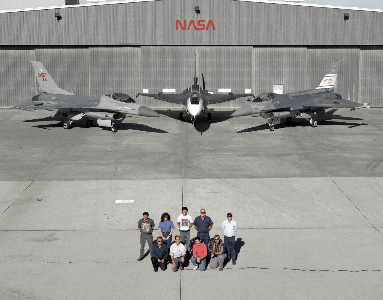
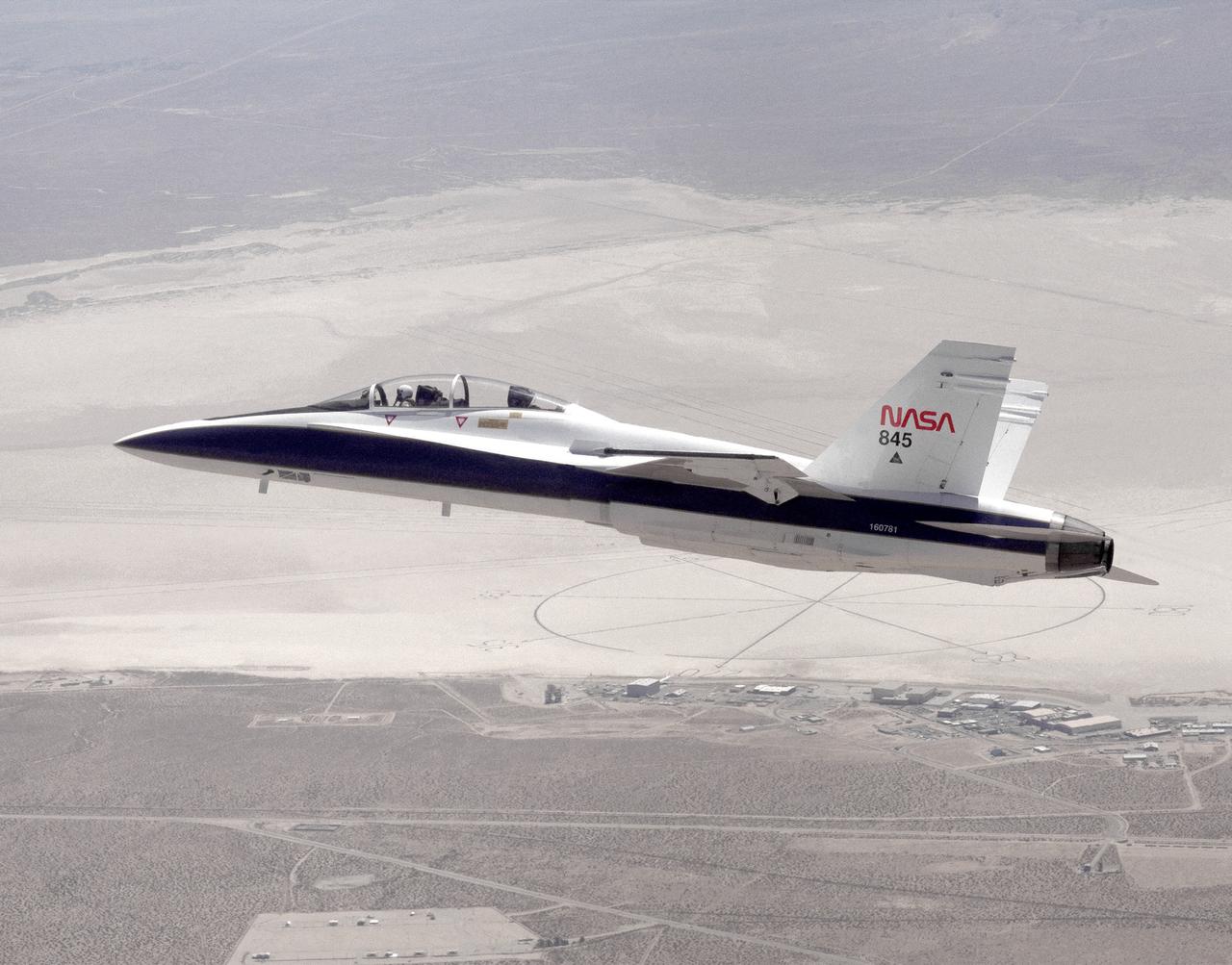
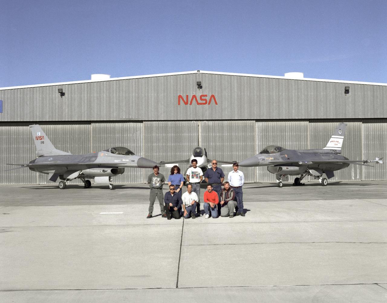
The support crew for the F-16A, the F-16XL no. 1, and the F-16 AFTI are, top row, left to right: Randy Weaver; mechanic, Susan Ligon; mechanic, Bob Garcia; Crew Chief, Rich Kelly; mechanic, Dale Edminister; Avionics Technician. Bottom row, left to right, Art Cope; mechanic, John Huffman; Avionics Technician, Jaime Garcia; Avionics Technician, Don Griffith, Avionics Tech. Co-op student. The F-16A (NASA 516), the only civil registered F-16 in existence, was transferred to Dryden from Langley, and was primarily used in engine tests and for parts. It was subsequently transfered from Dryden. The single-seat F-16XL no. 1 (NASA 849) was most recently used in the Cranked-Arrow Wing Aerodynamics Project (CAWAP) to test boundary layer pressures and distribution. Previously it had been used in a program to investigate the characteristics of sonic booms for NASA's High Speed Research Program. Data from the program will be used in the development of a high speed civilian transport. During the series of sonic boom research flights, the F-16XL was used to probe the shock waves being generated by a NASA SR-71 and record their shape and intensity. The Advanced Fighter Technology Integration (AFTI) F-16 was used to develop and demonstrate technologies to improve navigation and a pilot's ability to find and destroy enemy ground targets day or night, including adverse weather. Earlier research in the joint NASA-Air Force AFTI F-16 program demonstrated voice actuated controls, helmet-mounted sighting and integration of forward-mounted canards with the standard flight control system to achieve uncoupled flight.
A major component of NASA's Psyche spacecraft has been delivered to the agency's Jet Propulsion Laboratory in Southern California, where the phase known as assembly, test, and launch operations (ATLO) is now underway. Taken on March 28, 2021, this photo shows the Solar Electric Propulsion (SEP) Chassis just after it was delivered to JPL by Maxar Technologies. Here, the chassis is about to be attached to the dolly in High Bay 1 of JPL's Spacecraft Assembly Facility. Maxar's team in Palo Alto, California, designed and built the SEP Chassis, which includes all the primary and secondary structure and the hardware components needed for the high-power electrical system, the propulsion system, the thermal system, guidance and navigation sensors and actuators, and the high-gain antenna. Over the next year additional hardware will be added to the spacecraft, including the command and data handling system, a power distribution assembly, the X-band telecommunications hardware suite, three science instruments (two imagers, two magnetometers, and a Gamma Ray Neutron Spectrometer), and a deep space optical communications technology demonstrator. The spacecraft will finish assembly and then undergo rigorous checkout and testing before being shipped to NASA's Kennedy Space Center in Cape Canaveral, Florida, for an August 2022 launch to the main asteroid belt. Psyche will arrive at the metal-rich asteroid of the same name in 2026, orbiting for 21 months to investigate its composition. Scientists think that Psyche is made up of mostly iron and nickel — similar to Earth's core. Exploring the asteroid could give valuable insight into how our own planet and others formed. https://photojournal.jpl.nasa.gov/catalog/PIA24474
The support crew for the F-16A, the F-16XL no. 1, and the F-16 AFTI are, top row, left to right: Randy Weaver; mechanic, Susan Ligon; mechanic, Bob Garcia; Crew Chief, Rich Kelly; mechanic, Dale Edminister; Avionics Technician. Bottom row, left to right, Art Cope; mechanic, John Huffman; Avionics Technician, Jaime Garcia; Avionics Technician, Don Griffith, Avionics Tech. Co-op student. The F-16A (NASA 516), the only civil registered F-16 in existence, was transferred to Dryden from Langley, and was primarily used in engine tests and for parts. It was subsequently transfered from Dryden. The single-seat F-16XL no. 1 (NASA 849) was most recently used in the Cranked-Arrow Wing Aerodynamics Project (CAWAP) to test boundary layer pressures and distribution. Previously it had been used in a program to investigate the characteristics of sonic booms for NASA's High Speed Research Program. Data from the program will be used in the development of a high speed civilian transport. During the series of sonic boom research flights, the F-16XL was used to probe the shock waves being generated by a NASA SR-71 and record their shape and intensity. The Advanced Fighter Technology Integration (AFTI) F-16 was used to develop and demonstrate technologies to improve navigation and a pilot's ability to find and destroy enemy ground targets day or night, including adverse weather. Earlier research in the joint NASA-Air Force AFTI F-16 program demonstrated voice actuated controls, helmet-mounted sighting and integration of forward-mounted canards with the standard flight control system to achieve uncoupled flight.
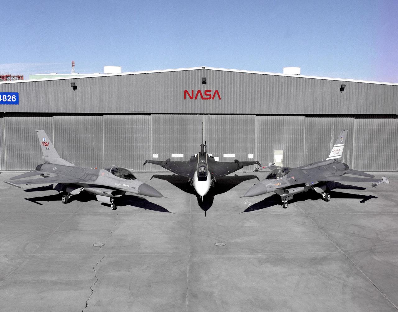
Photographed outside their hangar at the Dryden Flight Research Center, Edwards, California, part of Dryden's F-16 fleet is, left to right; an F-16A, the F-16XL no. 1, and the F-16 AFTI. The F-16A (NASA 516), the only civil registered F-16 in existence, was transferred to Dryden from Langley, and was primarily used in engine tests and for parts. It was subsequently transfered from Dryden. The single-seat F-16XL no. 1 (NASA 849) was most recently used in the Cranked-Arrow Wing Aerodynamics Project (CAWAP) to test boundary layer pressures and distribution. Previously it had been used in a program to investigate the characteristics of sonic booms for NASA's High Speed Research Program. Data from the program will be used in the development of a high speed civilian transport. During the series of sonic boom research flights, the F-16XL was used to probe the shock waves being generated by a NASA SR-71 and record their shape and intensity. The Advanced Fighter Technology Integration (AFTI) F-16 was used to develop and demonstrate technologies to improve navigation and a pilot's ability to find and destroy enemy ground targets day or night, including adverse weather. Earlier research in the joint NASA-Air Force AFTI F-16 program demonstrated voice actuated controls, helmet-mounted sighting and integration of forward-mounted canards with the standard flight control system to achieve uncoupled flight.

A major component of NASA's Psyche spacecraft has been delivered to NASA's Jet Propulsion Laboratory in Southern California, where the phase known as assembly, test, and launch operations (ATLO) is now underway. This photo, shot March 28, 2021 shows engineers and technicians preparing to move the Solar Electric Propulsion (SEP) Chassis from its shipping container to a dolly in High Bay 1 of JPL's Spacecraft Assembly Facility. The photo was captured just after the chassis was delivered to JPL by Maxar Technologies. Maxar's team in Palo Alto, California, designed and built the SEP Chassis, which includes all the primary and secondary structure and the hardware components needed for the high-power electrical system, the propulsion system, the thermal system, guidance and navigation sensors and actuators, and the high-gain antenna. Over the next year, additional hardware will be added to the spacecraft including the command and data handling system, a power distribution assembly, the X-band telecommunications hardware suite, three science instruments (two imagers, two magnetometers, and a gamma ray neutron Spectrometer), and a deep space optical communications technology demonstrator. The spacecraft will finish assembly and then undergo rigorous checkout and testing before being shipped to NASA's Kennedy Space Center in Cape Canaveral, Florida, for an August 2022 launch to the main asteroid belt. Psyche will arrive at the metal-rich asteroid of the same name in 2026, orbiting for 21 months to investigate its composition. Scientists think that Psyche is made up of mostly iron and nickel — similar to Earth's core. Exploring the asteroid could give valuable insight into how our own planet and others formed. https://photojournal.jpl.nasa.gov/catalog/PIA24475