
NASA astronauts Christina Koch and Victor J. Glover examine a sample of AVCOAT Thermal Protection System (TPS) that protects the Orion spacecraft as it enters Earth’s atmosphere.
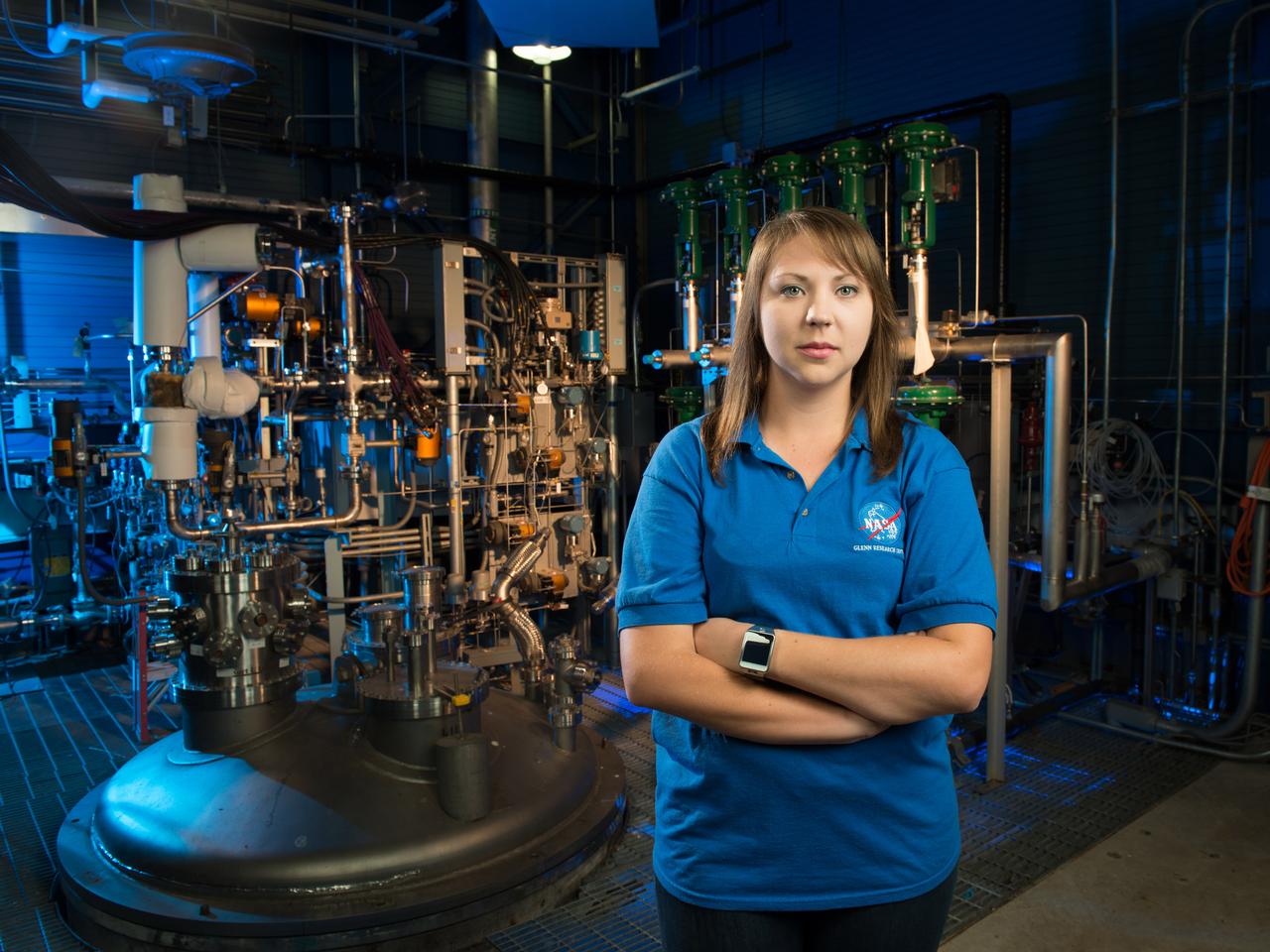
NASA Glenn engineer Monica Guzik in the Small Multi-Purpose Research Facility (SMiRF). The facility provides the ability to simulate the environmental conditions encountered in space for a variety of cryogenic applications such as thermal protection systems, fluid transfer operations and propellant level gauging. SMiRF is a low-cost, small-scale screening facility for concept and component testing of a wide variety of hardware and is capable of testing cryogenic hydrogen, oxygen, methane and nitrogen.
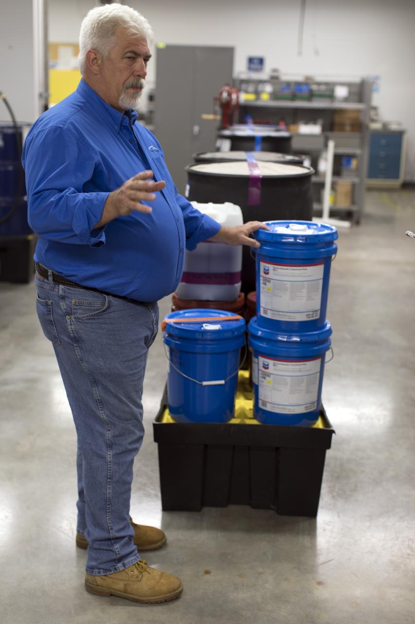
Tim King of Jacobs at NASA's Kennedy Space Center in Florida, explains operations in the Oil Pharmacy operated under the Test and Operations Support Contract, or TOSC. The facility consolidated storage and distribution of petroleum products used in equipment maintained under the contract. This included standardized naming, testing processes and provided a central location for distribution of oils used in everything from simple machinery to the crawler-transporter and cranes in the Vehicle Assembly Building.
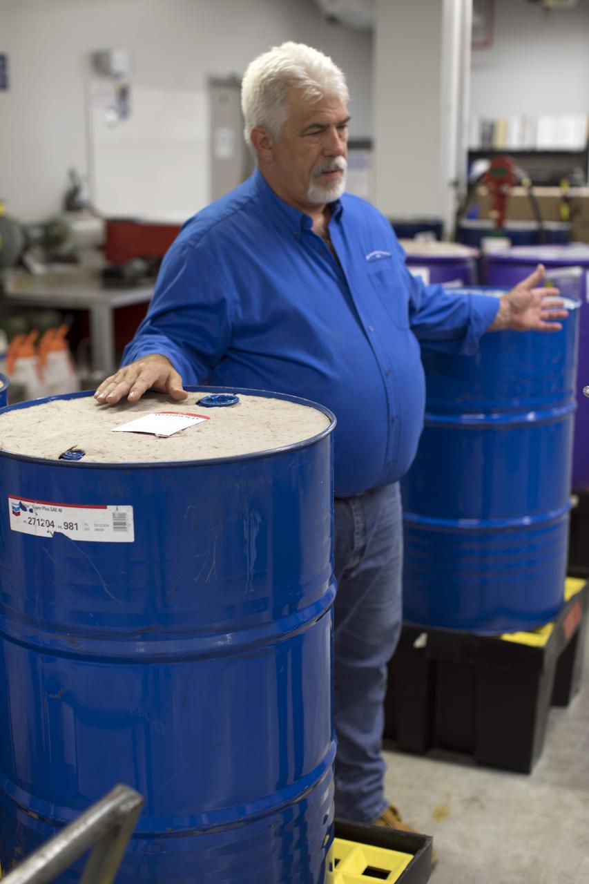
Tim King of Jacobs at NASA's Kennedy Space Center in Florida, explains operations in the Oil Pharmacy operated under the Test and Operations Support Contract, or TOSC. The facility consolidated storage and distribution of petroleum products used in equipment maintained under the contract. This included standardized naming, testing processes and provided a central location for distribution of oils used in everything from simple machinery to the crawler-transporter and cranes in the Vehicle Assembly Building.
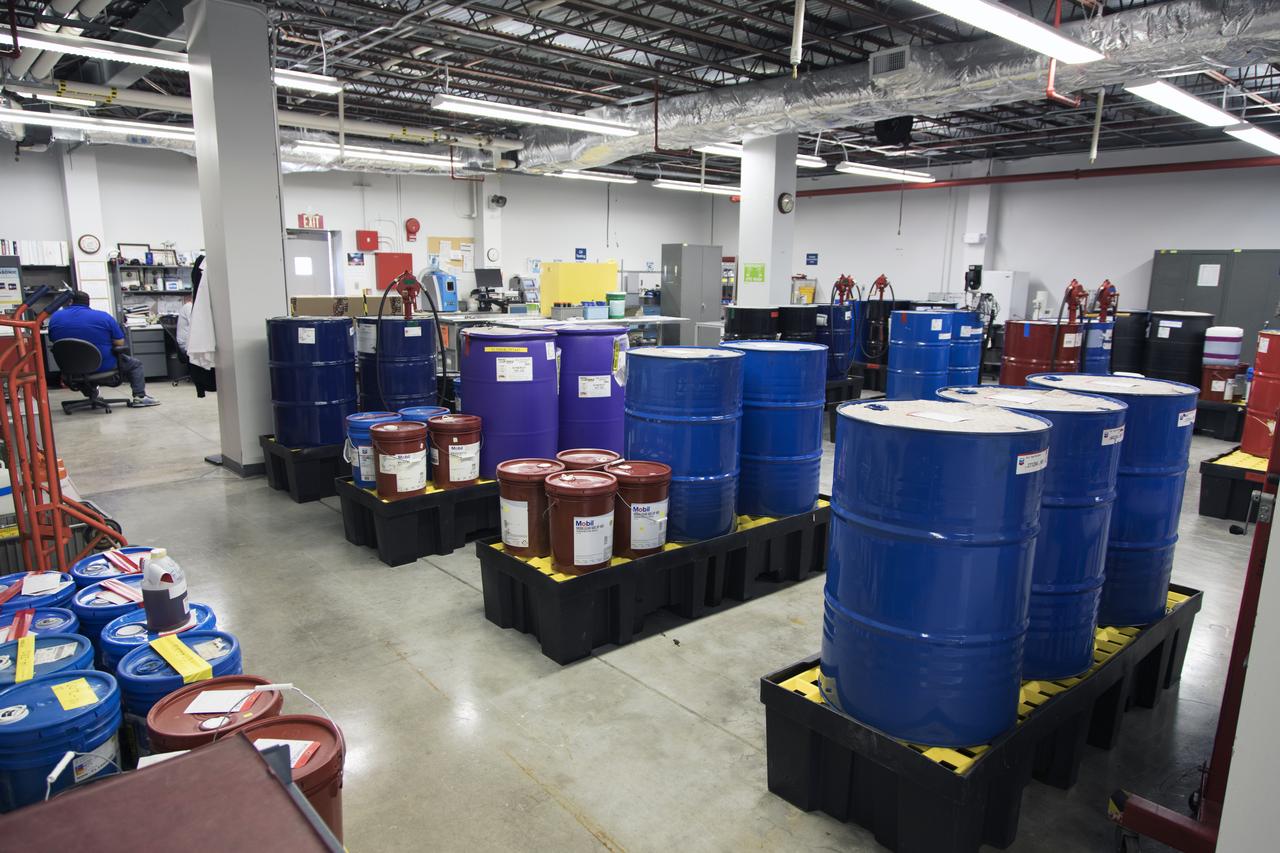
An overall view of the Oil Pharmacy operated under the Test and Operations Support Contract, or TOSC. The facility consolidated storage and distribution of petroleum products used in equipment maintained under the contract. This included standardized naming, testing processes and provided a central location for distribution of oils used in everything from simple machinery to the crawler-transporter and cranes in the Vehicle Assembly Building.
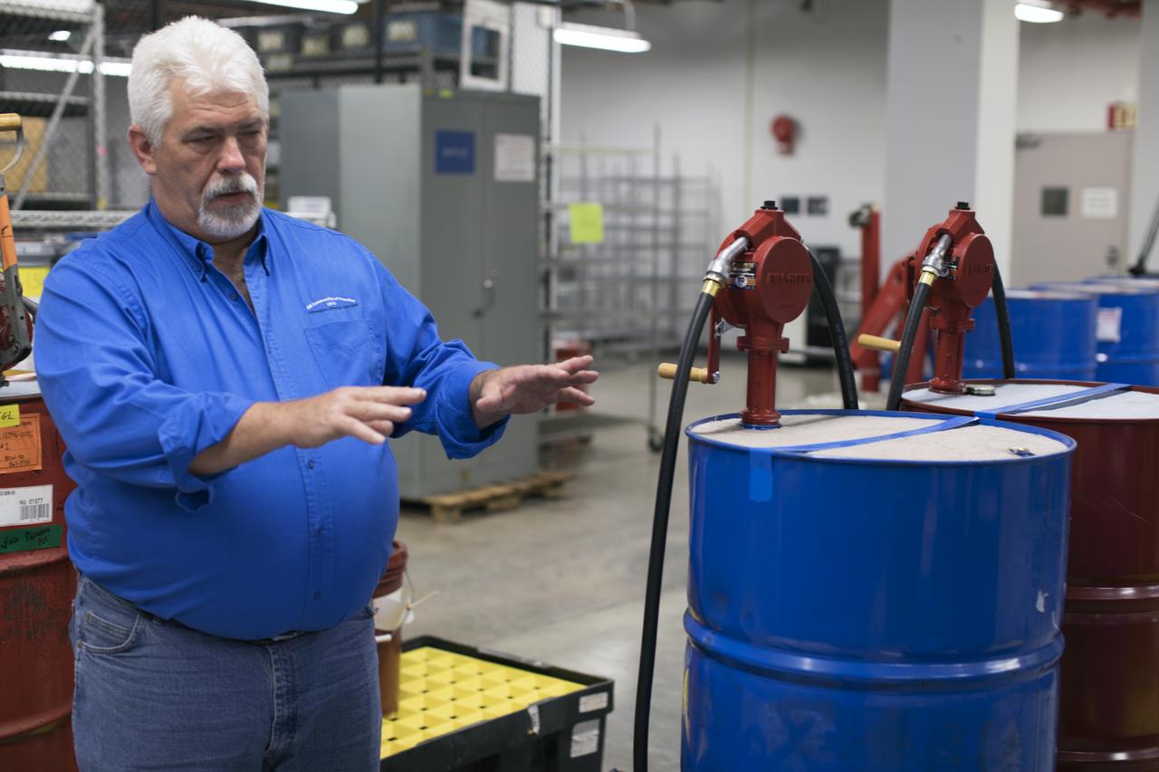
Tim King of Jacobs at NASA's Kennedy Space Center in Florida, explains operations in the Oil Pharmacy operated under the Test and Operations Support Contract, or TOSC. The facility consolidated storage and distribution of petroleum products used in equipment maintained under the contract. This included standardized naming, testing processes and provided a central location for distribution of oils used in everything from simple machinery to the crawler-transporter and cranes in the Vehicle Assembly Building.
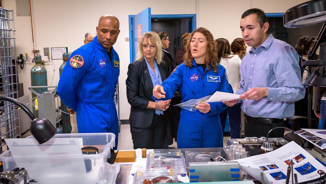
Jose A. B. Santos, right, discusses thermal protection materials with NASA astronaut Victor J. Glover, Orion Deputy Program Manager Debbie Korth, and NASA astronaut Christina Koch in STAR Labs in N242.
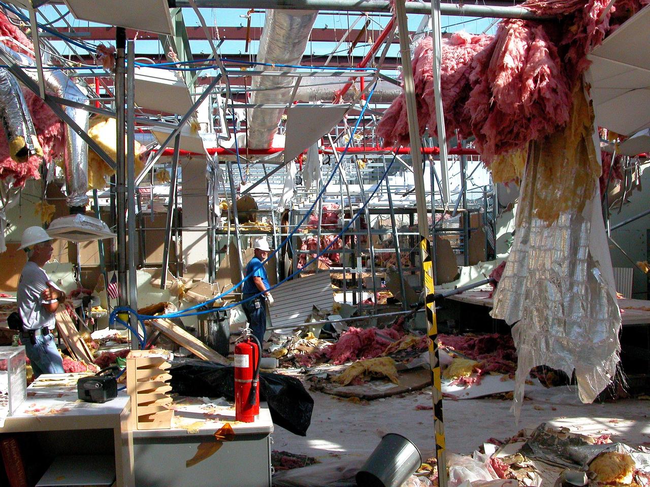
KENNEDY SPACE CENTER, FLA. - KSC employees clean up inside the second floor of the Thermal Protection System Facility damaged by Hurricane Frances. The storm's path over Florida took it through Cape Canaveral and KSC property during Labor Day weekend. Located in Launch Complex 39, the facility is used to manufacture both internal and external insulation products for the Space Shuttle orbiters.
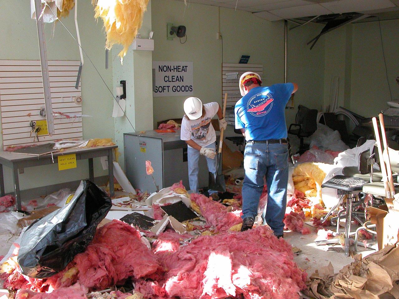
KENNEDY SPACE CENTER, FLA. - KSC employees clean up inside the second floor of the Thermal Protection System Facility damaged by Hurricane Frances. The storm's path over Florida took it through Cape Canaveral and KSC property during Labor Day weekend. Located in Launch Complex 39, the facility is used to manufacture both internal and external insulation products for the Space Shuttle orbiters.
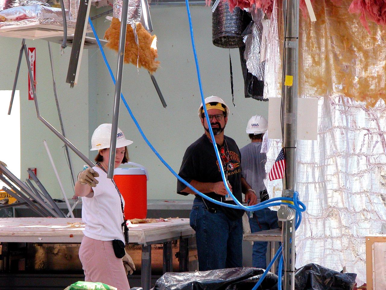
KENNEDY SPACE CENTER, FLA. - KSC employees clean up inside the second floor of the Thermal Protection System Facility damaged by Hurricane Frances. The storm's path over Florida took it through Cape Canaveral and KSC property during Labor Day weekend. Located in Launch Complex 39, the facility is used to manufacture both internal and external insulation products for the Space Shuttle orbiters.
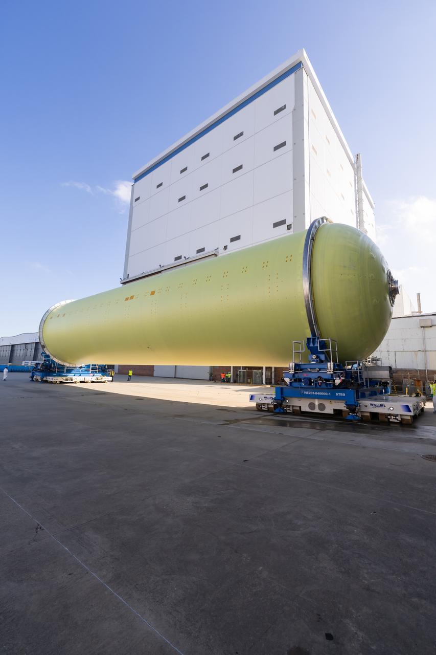
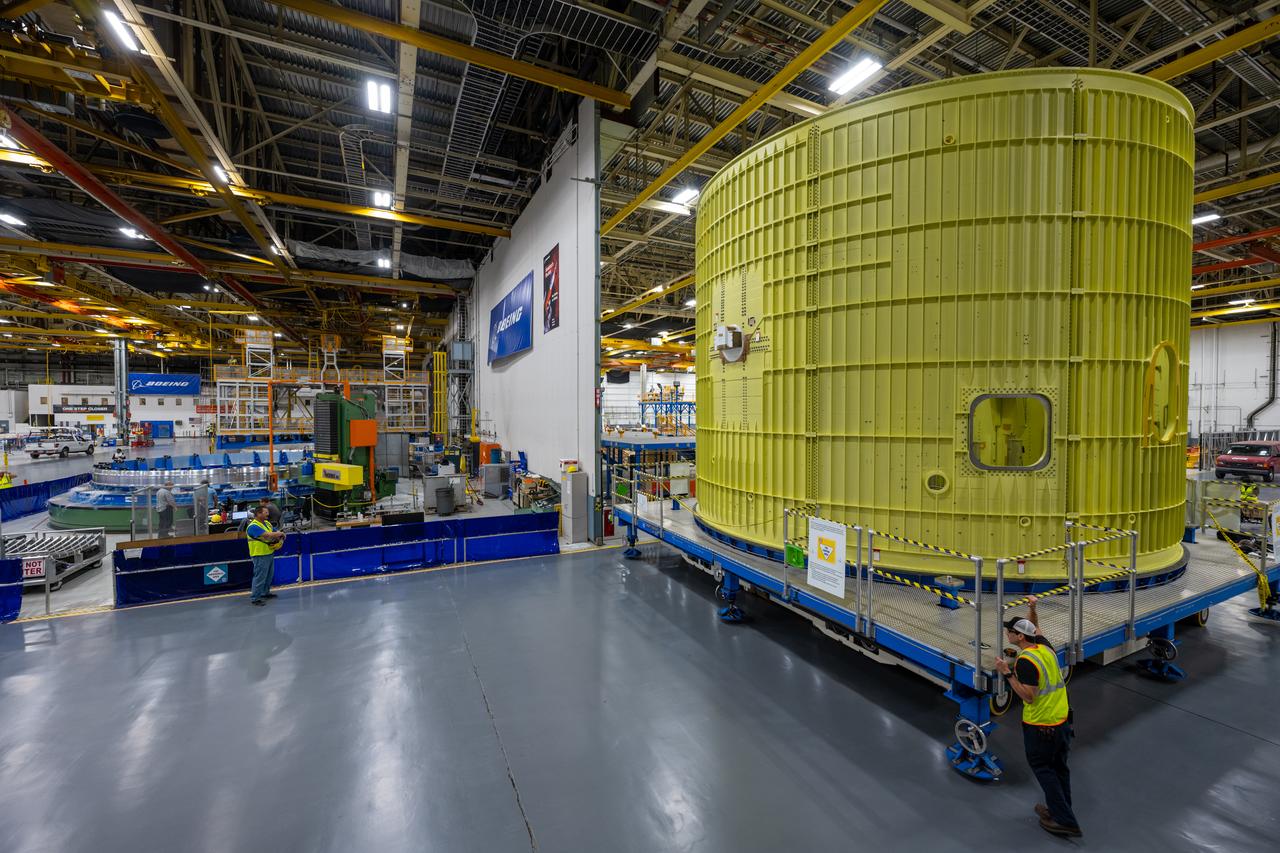
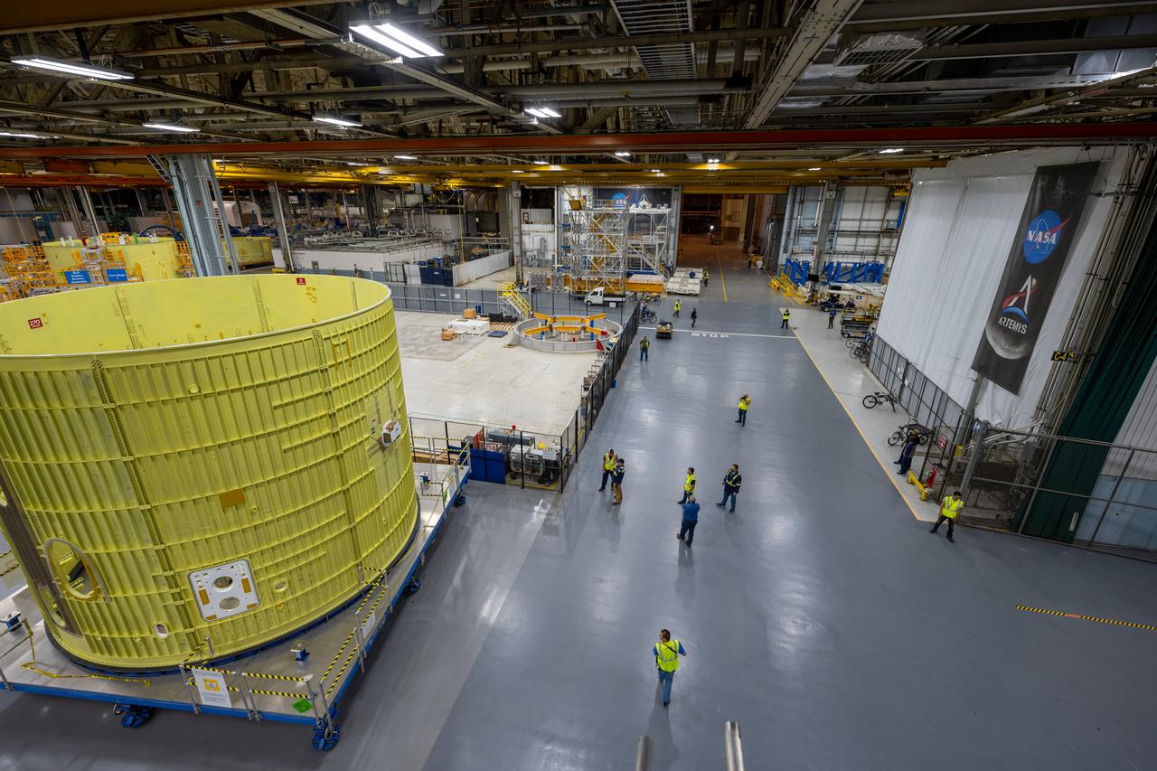
Teams move a liquid hydrogen tank for NASA’s SLS (Space Launch System) rocket out of a priming cell and into an adjacent cell on May 20 at the agency’s Michoud Assembly Facility in New Orleans. Inside the cell, the tank, which will be used on the core stage of NASA’s Artemis III mission, will receive its thermal protection system. The thermal protection system, or spray-on foam insulation, provides protection to the core stage during launch. It is flexible enough to move with the rocket yet can withstand the aerodynamic pressures as the SLS accelerates from 0 to 17,500 mph and soars to more than 100 miles above the Earth. This third-generation insulation is more environmentally friendly and keeps the cryogenic propellant, which powers the rocket’s four RS-25 engines, extremely cold (the liquid hydrogen must remain at minus 423 degrees Fahrenheit/253 degrees Celsius) to remain in its liquid state. When applied the thermal protection system is a light-yellow color, which “tans” once exposed to the Sun’s ultraviolet rays, giving the SLS core stage its signature orange color.
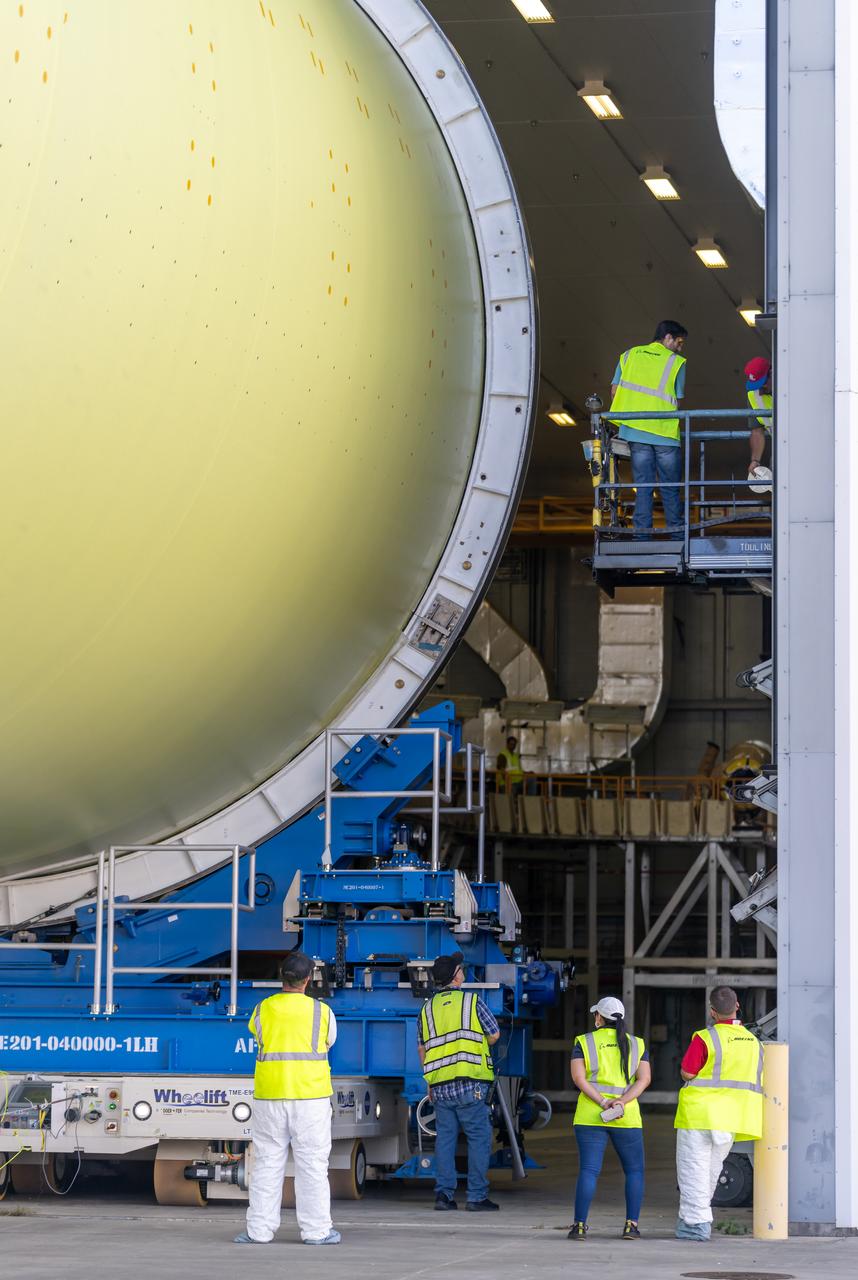
Teams move a liquid hydrogen tank for NASA’s SLS (Space Launch System) rocket out of a priming cell and into an adjacent cell on May 20 at the agency’s Michoud Assembly Facility in New Orleans. Inside the cell, the tank, which will be used on the core stage of NASA’s Artemis III mission, will receive its thermal protection system. The thermal protection system, or spray-on foam insulation, provides protection to the core stage during launch. It is flexible enough to move with the rocket yet can withstand the aerodynamic pressures as the SLS accelerates from 0 to 17,500 mph and soars to more than 100 miles above the Earth. This third-generation insulation is more environmentally friendly and keeps the cryogenic propellant, which powers the rocket’s four RS-25 engines, extremely cold (the liquid hydrogen must remain at minus 423 degrees Fahrenheit/253 degrees Celsius) to remain in its liquid state. When applied the thermal protection system is a light-yellow color, which “tans” once exposed to the Sun’s ultraviolet rays, giving the SLS core stage its signature orange color.
Teams move a liquid hydrogen tank for NASA’s SLS (Space Launch System) rocket out of a priming cell and into an adjacent cell on May 20 at the agency’s Michoud Assembly Facility in New Orleans. Inside the cell, the tank, which will be used on the core stage of NASA’s Artemis III mission, will receive its thermal protection system. The thermal protection system, or spray-on foam insulation, provides protection to the core stage during launch. It is flexible enough to move with the rocket yet can withstand the aerodynamic pressures as the SLS accelerates from 0 to 17,500 mph and soars to more than 100 miles above the Earth. This third-generation insulation is more environmentally friendly and keeps the cryogenic propellant, which powers the rocket’s four RS-25 engines, extremely cold (the liquid hydrogen must remain at minus 423 degrees Fahrenheit/253 degrees Celsius) to remain in its liquid state. When applied the thermal protection system is a light-yellow color, which “tans” once exposed to the Sun’s ultraviolet rays, giving the SLS core stage its signature orange color.
Teams move a liquid hydrogen tank for NASA’s SLS (Space Launch System) rocket out of a priming cell and into an adjacent cell on May 20 at the agency’s Michoud Assembly Facility in New Orleans. Inside the cell, the tank, which will be used on the core stage of NASA’s Artemis III mission, will receive its thermal protection system. The thermal protection system, or spray-on foam insulation, provides protection to the core stage during launch. It is flexible enough to move with the rocket yet can withstand the aerodynamic pressures as the SLS accelerates from 0 to 17,500 mph and soars to more than 100 miles above the Earth. This third-generation insulation is more environmentally friendly and keeps the cryogenic propellant, which powers the rocket’s four RS-25 engines, extremely cold (the liquid hydrogen must remain at minus 423 degrees Fahrenheit/253 degrees Celsius) to remain in its liquid state. When applied the thermal protection system is a light-yellow color, which “tans” once exposed to the Sun’s ultraviolet rays, giving the SLS core stage its signature orange color.
Teams move a liquid hydrogen tank for NASA’s SLS (Space Launch System) rocket out of a priming cell and into an adjacent cell on May 20 at the agency’s Michoud Assembly Facility in New Orleans. Inside the cell, the tank, which will be used on the core stage of NASA’s Artemis III mission, will receive its thermal protection system. The thermal protection system, or spray-on foam insulation, provides protection to the core stage during launch. It is flexible enough to move with the rocket yet can withstand the aerodynamic pressures as the SLS accelerates from 0 to 17,500 mph and soars to more than 100 miles above the Earth. This third-generation insulation is more environmentally friendly and keeps the cryogenic propellant, which powers the rocket’s four RS-25 engines, extremely cold (the liquid hydrogen must remain at minus 423 degrees Fahrenheit/253 degrees Celsius) to remain in its liquid state. When applied the thermal protection system is a light-yellow color, which “tans” once exposed to the Sun’s ultraviolet rays, giving the SLS core stage its signature orange color.
Teams move a liquid hydrogen tank for NASA’s SLS (Space Launch System) rocket out of a priming cell and into an adjacent cell on May 20 at the agency’s Michoud Assembly Facility in New Orleans. Inside the cell, the tank, which will be used on the core stage of NASA’s Artemis III mission, will receive its thermal protection system. The thermal protection system, or spray-on foam insulation, provides protection to the core stage during launch. It is flexible enough to move with the rocket yet can withstand the aerodynamic pressures as the SLS accelerates from 0 to 17,500 mph and soars to more than 100 miles above the Earth. This third-generation insulation is more environmentally friendly and keeps the cryogenic propellant, which powers the rocket’s four RS-25 engines, extremely cold (the liquid hydrogen must remain at minus 423 degrees Fahrenheit/253 degrees Celsius) to remain in its liquid state. When applied the thermal protection system is a light-yellow color, which “tans” once exposed to the Sun’s ultraviolet rays, giving the SLS core stage its signature orange color.
Teams move a liquid hydrogen tank for NASA’s SLS (Space Launch System) rocket out of a priming cell and into an adjacent cell on May 20 at the agency’s Michoud Assembly Facility in New Orleans. Inside the cell, the tank, which will be used on the core stage of NASA’s Artemis III mission, will receive its thermal protection system. The thermal protection system, or spray-on foam insulation, provides protection to the core stage during launch. It is flexible enough to move with the rocket yet can withstand the aerodynamic pressures as the SLS accelerates from 0 to 17,500 mph and soars to more than 100 miles above the Earth. This third-generation insulation is more environmentally friendly and keeps the cryogenic propellant, which powers the rocket’s four RS-25 engines, extremely cold (the liquid hydrogen must remain at minus 423 degrees Fahrenheit/253 degrees Celsius) to remain in its liquid state. When applied the thermal protection system is a light-yellow color, which “tans” once exposed to the Sun’s ultraviolet rays, giving the SLS core stage its signature orange color.
Teams move a liquid hydrogen tank for NASA’s SLS (Space Launch System) rocket out of a priming cell and into an adjacent cell on May 20 at the agency’s Michoud Assembly Facility in New Orleans. Inside the cell, the tank, which will be used on the core stage of NASA’s Artemis III mission, will receive its thermal protection system. The thermal protection system, or spray-on foam insulation, provides protection to the core stage during launch. It is flexible enough to move with the rocket yet can withstand the aerodynamic pressures as the SLS accelerates from 0 to 17,500 mph and soars to more than 100 miles above the Earth. This third-generation insulation is more environmentally friendly and keeps the cryogenic propellant, which powers the rocket’s four RS-25 engines, extremely cold (the liquid hydrogen must remain at minus 423 degrees Fahrenheit/253 degrees Celsius) to remain in its liquid state. When applied the thermal protection system is a light-yellow color, which “tans” once exposed to the Sun’s ultraviolet rays, giving the SLS core stage its signature orange color.
Teams move a liquid hydrogen tank for NASA’s SLS (Space Launch System) rocket out of a priming cell and into an adjacent cell on May 20 at the agency’s Michoud Assembly Facility in New Orleans. Inside the cell, the tank, which will be used on the core stage of NASA’s Artemis III mission, will receive its thermal protection system. The thermal protection system, or spray-on foam insulation, provides protection to the core stage during launch. It is flexible enough to move with the rocket yet can withstand the aerodynamic pressures as the SLS accelerates from 0 to 17,500 mph and soars to more than 100 miles above the Earth. This third-generation insulation is more environmentally friendly and keeps the cryogenic propellant, which powers the rocket’s four RS-25 engines, extremely cold (the liquid hydrogen must remain at minus 423 degrees Fahrenheit/253 degrees Celsius) to remain in its liquid state. When applied the thermal protection system is a light-yellow color, which “tans” once exposed to the Sun’s ultraviolet rays, giving the SLS core stage its signature orange color.
Teams move a liquid hydrogen tank for NASA’s SLS (Space Launch System) rocket out of a priming cell and into an adjacent cell on May 20 at the agency’s Michoud Assembly Facility in New Orleans. Inside the cell, the tank, which will be used on the core stage of NASA’s Artemis III mission, will receive its thermal protection system. The thermal protection system, or spray-on foam insulation, provides protection to the core stage during launch. It is flexible enough to move with the rocket yet can withstand the aerodynamic pressures as the SLS accelerates from 0 to 17,500 mph and soars to more than 100 miles above the Earth. This third-generation insulation is more environmentally friendly and keeps the cryogenic propellant, which powers the rocket’s four RS-25 engines, extremely cold (the liquid hydrogen must remain at minus 423 degrees Fahrenheit/253 degrees Celsius) to remain in its liquid state. When applied the thermal protection system is a light-yellow color, which “tans” once exposed to the Sun’s ultraviolet rays, giving the SLS core stage its signature orange color.
Teams move a liquid hydrogen tank for NASA’s SLS (Space Launch System) rocket out of a priming cell and into an adjacent cell on May 20 at the agency’s Michoud Assembly Facility in New Orleans. Inside the cell, the tank, which will be used on the core stage of NASA’s Artemis III mission, will receive its thermal protection system. The thermal protection system, or spray-on foam insulation, provides protection to the core stage during launch. It is flexible enough to move with the rocket yet can withstand the aerodynamic pressures as the SLS accelerates from 0 to 17,500 mph and soars to more than 100 miles above the Earth. This third-generation insulation is more environmentally friendly and keeps the cryogenic propellant, which powers the rocket’s four RS-25 engines, extremely cold (the liquid hydrogen must remain at minus 423 degrees Fahrenheit/253 degrees Celsius) to remain in its liquid state. When applied the thermal protection system is a light-yellow color, which “tans” once exposed to the Sun’s ultraviolet rays, giving the SLS core stage its signature orange color.

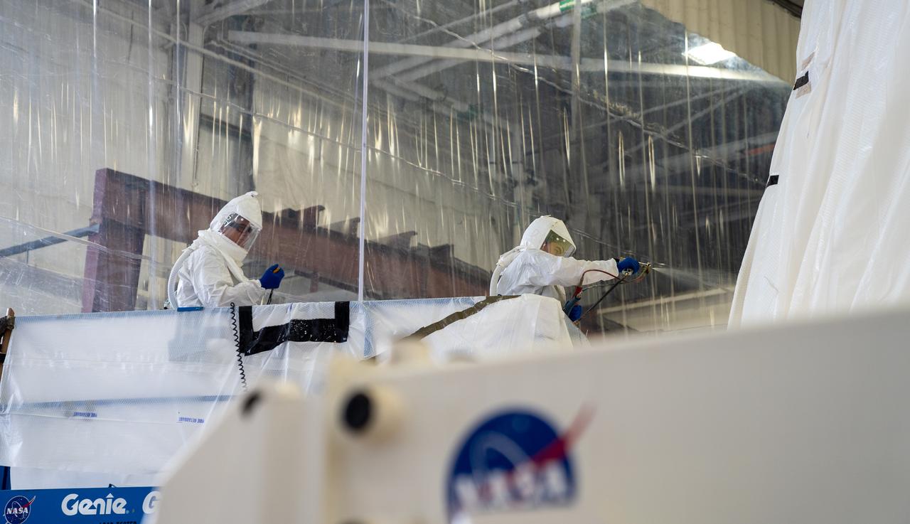
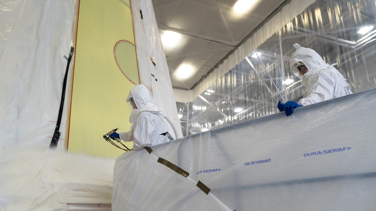
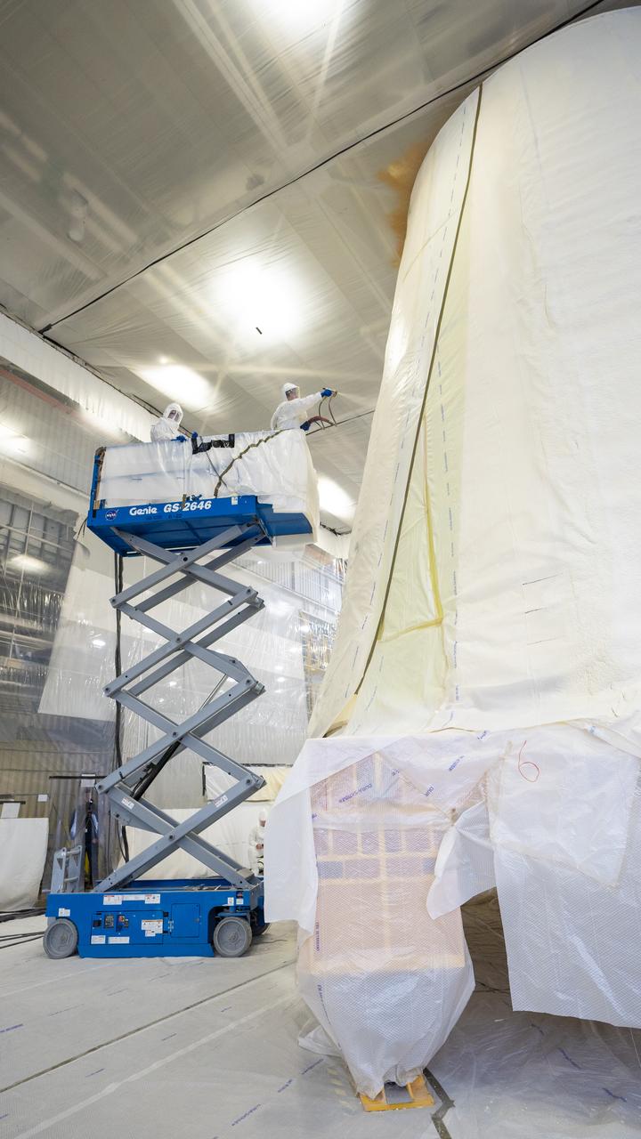
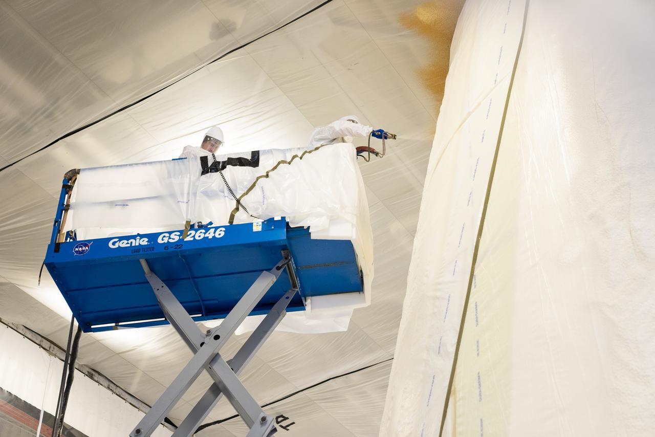
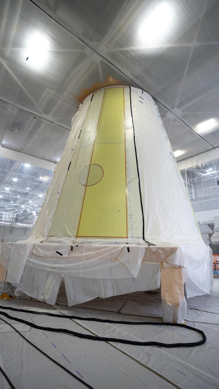
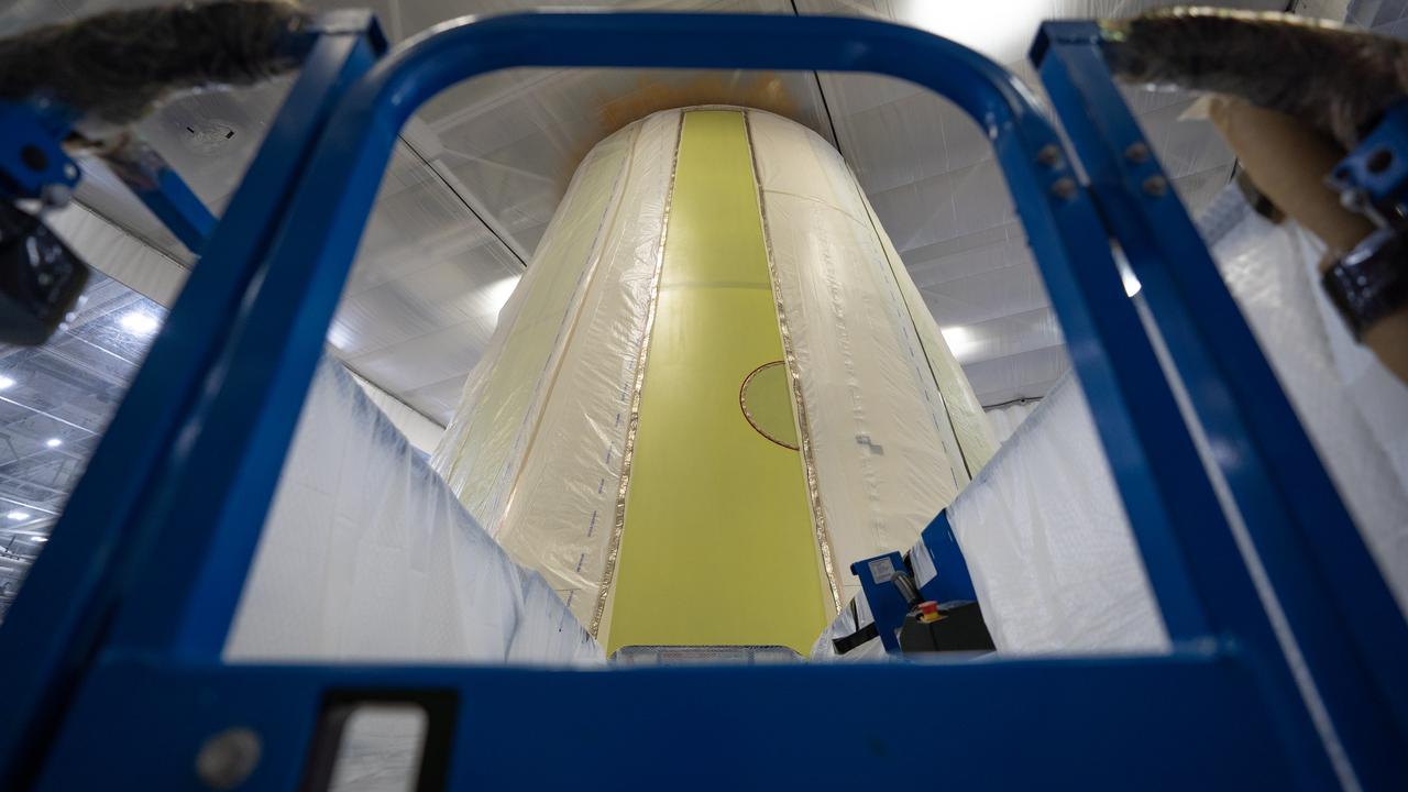
These photos show how technicians at NASA’s Marshall Space Flight Center in Huntsville, Alabama, have applied the thermal protection system material to the launch vehicle stage adapter (LVSA) of NASA’s SLS (Space Launch System) rocket for Artemis III, which will land astronauts on the Moon to advance long-term lunar exploration and scientific discovery and inspire the Artemis Generation. The LVSA is a cone-shaped element that connects the mega rocket’s core stage to its interim cryogenic propulsion stage (ICPS), partially enclosing it and protecting its avionics and electrical systems from the extreme pressures, sounds, and temperatures during launch and flight. Teams at Marshall began applying the thermal protection system material in the spring of 2023. Unlike other parts of the SLS rocket, the thermal protection system material for the LVSA is applied entirely by hand using a spray gun. During application, the technicians use a thin measuring rod to gauge the proper thickness. Once the thermal protection system has cured, certain areas are sanded down to meet parameters. The entire process takes several months. The LVSA is fully manufactured at Marshall by NASA, lead contractor Teledyne Brown Engineering, and the Jacobs Space Group’s ESSCA contract. The LVSA for Artemis III is the last of its kind as future SLS rockets will transition to its next, more powerful Block 1B configuration beginning with Artemis IV. NASA is working to land the first woman and first person of color on the Moon under Artemis. SLS is part of NASA’s backbone for deep space exploration, along with the Orion spacecraft, advanced spacesuits and rovers, the Gateway in orbit around the Moon, and commercial human landing systems. SLS is the only rocket that can send Orion, astronauts, and supplies to the Moon in a single mission.
These photos show how technicians at NASA’s Marshall Space Flight Center in Huntsville, Alabama, have applied the thermal protection system material to the launch vehicle stage adapter (LVSA) of NASA’s SLS (Space Launch System) rocket for Artemis III, which will land astronauts on the Moon to advance long-term lunar exploration and scientific discovery and inspire the Artemis Generation. The LVSA is a cone-shaped element that connects the mega rocket’s core stage to its interim cryogenic propulsion stage (ICPS), partially enclosing it and protecting its avionics and electrical systems from the extreme pressures, sounds, and temperatures during launch and flight. Teams at Marshall began applying the thermal protection system material in the spring of 2023. Unlike other parts of the SLS rocket, the thermal protection system material for the LVSA is applied entirely by hand using a spray gun. During application, the technicians use a thin measuring rod to gauge the proper thickness. Once the thermal protection system has cured, certain areas are sanded down to meet parameters. The entire process takes several months. The LVSA is fully manufactured at Marshall by NASA, lead contractor Teledyne Brown Engineering, and the Jacobs Space Group’s ESSCA contract. The LVSA for Artemis III is the last of its kind as future SLS rockets will transition to its next, more powerful Block 1B configuration beginning with Artemis IV. NASA is working to land the first woman and first person of color on the Moon under Artemis. SLS is part of NASA’s backbone for deep space exploration, along with the Orion spacecraft, advanced spacesuits and rovers, the Gateway in orbit around the Moon, and commercial human landing systems. SLS is the only rocket that can send Orion, astronauts, and supplies to the Moon in a single mission.
These photos show how technicians at NASA’s Marshall Space Flight Center in Huntsville, Alabama, have applied the thermal protection system material to the launch vehicle stage adapter (LVSA) of NASA’s SLS (Space Launch System) rocket for Artemis III, which will land astronauts on the Moon to advance long-term lunar exploration and scientific discovery and inspire the Artemis Generation. The LVSA is a cone-shaped element that connects the mega rocket’s core stage to its interim cryogenic propulsion stage (ICPS), partially enclosing it and protecting its avionics and electrical systems from the extreme pressures, sounds, and temperatures during launch and flight. Teams at Marshall began applying the thermal protection system material in the spring of 2023. Unlike other parts of the SLS rocket, the thermal protection system material for the LVSA is applied entirely by hand using a spray gun. During application, the technicians use a thin measuring rod to gauge the proper thickness. Once the thermal protection system has cured, certain areas are sanded down to meet parameters. The entire process takes several months. The LVSA is fully manufactured at Marshall by NASA, lead contractor Teledyne Brown Engineering, and the Jacobs Space Group’s ESSCA contract. The LVSA for Artemis III is the last of its kind as future SLS rockets will transition to its next, more powerful Block 1B configuration beginning with Artemis IV. NASA is working to land the first woman and first person of color on the Moon under Artemis. SLS is part of NASA’s backbone for deep space exploration, along with the Orion spacecraft, advanced spacesuits and rovers, the Gateway in orbit around the Moon, and commercial human landing systems. SLS is the only rocket that can send Orion, astronauts, and supplies to the Moon in a single mission.
These photos show how technicians at NASA’s Marshall Space Flight Center in Huntsville, Alabama, have applied the thermal protection system material to the launch vehicle stage adapter (LVSA) of NASA’s SLS (Space Launch System) rocket for Artemis III, which will land astronauts on the Moon to advance long-term lunar exploration and scientific discovery and inspire the Artemis Generation. The LVSA is a cone-shaped element that connects the mega rocket’s core stage to its interim cryogenic propulsion stage (ICPS), partially enclosing it and protecting its avionics and electrical systems from the extreme pressures, sounds, and temperatures during launch and flight. Teams at Marshall began applying the thermal protection system material in the spring of 2023. Unlike other parts of the SLS rocket, the thermal protection system material for the LVSA is applied entirely by hand using a spray gun. During application, the technicians use a thin measuring rod to gauge the proper thickness. Once the thermal protection system has cured, certain areas are sanded down to meet parameters. The entire process takes several months. The LVSA is fully manufactured at Marshall by NASA, lead contractor Teledyne Brown Engineering, and the Jacobs Space Group’s ESSCA contract. The LVSA for Artemis III is the last of its kind as future SLS rockets will transition to its next, more powerful Block 1B configuration beginning with Artemis IV. NASA is working to land the first woman and first person of color on the Moon under Artemis. SLS is part of NASA’s backbone for deep space exploration, along with the Orion spacecraft, advanced spacesuits and rovers, the Gateway in orbit around the Moon, and commercial human landing systems. SLS is the only rocket that can send Orion, astronauts, and supplies to the Moon in a single mission.
These photos show how technicians at NASA’s Marshall Space Flight Center in Huntsville, Alabama, have applied the thermal protection system material to the launch vehicle stage adapter (LVSA) of NASA’s SLS (Space Launch System) rocket for Artemis III, which will land astronauts on the Moon to advance long-term lunar exploration and scientific discovery and inspire the Artemis Generation. The LVSA is a cone-shaped element that connects the mega rocket’s core stage to its interim cryogenic propulsion stage (ICPS), partially enclosing it and protecting its avionics and electrical systems from the extreme pressures, sounds, and temperatures during launch and flight. Teams at Marshall began applying the thermal protection system material in the spring of 2023. Unlike other parts of the SLS rocket, the thermal protection system material for the LVSA is applied entirely by hand using a spray gun. During application, the technicians use a thin measuring rod to gauge the proper thickness. Once the thermal protection system has cured, certain areas are sanded down to meet parameters. The entire process takes several months. The LVSA is fully manufactured at Marshall by NASA, lead contractor Teledyne Brown Engineering, and the Jacobs Space Group’s ESSCA contract. The LVSA for Artemis III is the last of its kind as future SLS rockets will transition to its next, more powerful Block 1B configuration beginning with Artemis IV. NASA is working to land the first woman and first person of color on the Moon under Artemis. SLS is part of NASA’s backbone for deep space exploration, along with the Orion spacecraft, advanced spacesuits and rovers, the Gateway in orbit around the Moon, and commercial human landing systems. SLS is the only rocket that can send Orion, astronauts, and supplies to the Moon in a single mission.
These photos show how technicians at NASA’s Marshall Space Flight Center in Huntsville, Alabama, have applied the thermal protection system material to the launch vehicle stage adapter (LVSA) of NASA’s SLS (Space Launch System) rocket for Artemis III, which will land astronauts on the Moon to advance long-term lunar exploration and scientific discovery and inspire the Artemis Generation. The LVSA is a cone-shaped element that connects the mega rocket’s core stage to its interim cryogenic propulsion stage (ICPS), partially enclosing it and protecting its avionics and electrical systems from the extreme pressures, sounds, and temperatures during launch and flight. Teams at Marshall began applying the thermal protection system material in the spring of 2023. Unlike other parts of the SLS rocket, the thermal protection system material for the LVSA is applied entirely by hand using a spray gun. During application, the technicians use a thin measuring rod to gauge the proper thickness. Once the thermal protection system has cured, certain areas are sanded down to meet parameters. The entire process takes several months. The LVSA is fully manufactured at Marshall by NASA, lead contractor Teledyne Brown Engineering, and the Jacobs Space Group’s ESSCA contract. The LVSA for Artemis III is the last of its kind as future SLS rockets will transition to its next, more powerful Block 1B configuration beginning with Artemis IV. NASA is working to land the first woman and first person of color on the Moon under Artemis. SLS is part of NASA’s backbone for deep space exploration, along with the Orion spacecraft, advanced spacesuits and rovers, the Gateway in orbit around the Moon, and commercial human landing systems. SLS is the only rocket that can send Orion, astronauts, and supplies to the Moon in a single mission.
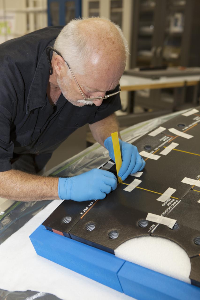
CAPE CANAVERAL, Fla. – Inside the Operations and Checkout Building high bay at NASA’s Kennedy Space Center in Florida, a tile technician places spacers between the thermal protection system tiles that will be installed on the Orion crew module. Orion is the exploration spacecraft designed to carry astronauts to destinations not yet explored by humans, including an asteroid and Mars. It will have emergency abort capability, sustain the crew during space travel and provide safe re-entry from deep space return velocities. The first unpiloted test flight of the Orion is scheduled to launch in 2014 atop a Delta IV rocket and in 2017 on NASA’s Space Launch System rocket. For more information, visit http://www.nasa.gov/orion. Photo credit: NASA/Dimitri Gerondidakis
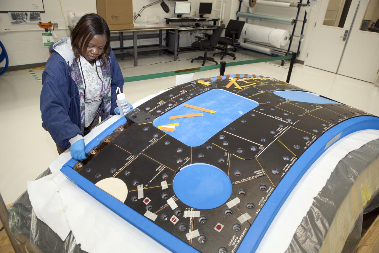
CAPE CANAVERAL, Fla. – Inside the Operations and Checkout Building high bay at NASA’s Kennedy Space Center in Florida, a tile technician works on a section of thermal protection system tiles that will be installed on the Orion crew module. Orion is the exploration spacecraft designed to carry astronauts to destinations not yet explored by humans, including an asteroid and Mars. It will have emergency abort capability, sustain the crew during space travel and provide safe re-entry from deep space return velocities. The first unpiloted test flight of the Orion is scheduled to launch in 2014 atop a Delta IV rocket and in 2017 on NASA’s Space Launch System rocket. For more information, visit http://www.nasa.gov/orion. Photo credit: NASA/Dimitri Gerondidakis
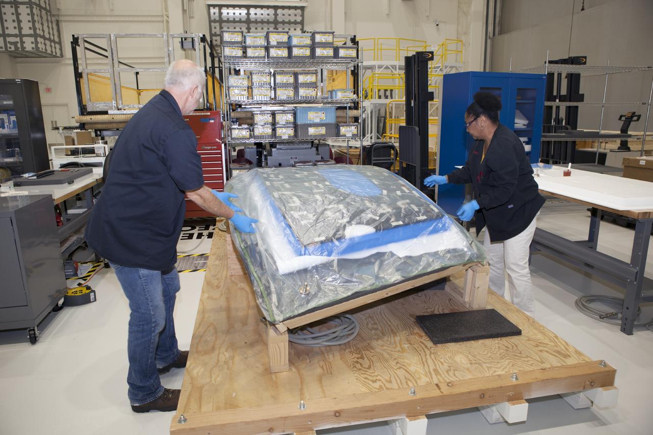
CAPE CANAVERAL, Fla. – Inside the Operations and Checkout Building high bay at NASA’s Kennedy Space Center in Florida, two tile technicians wrap a section of the thermal protection system tiles that will be installed on the Orion crew module. Orion is the exploration spacecraft designed to carry astronauts to destinations not yet explored by humans, including an asteroid and Mars. It will have emergency abort capability, sustain the crew during space travel and provide safe re-entry from deep space return velocities. The first unpiloted test flight of the Orion is scheduled to launch in 2014 atop a Delta IV rocket and in 2017 on NASA’s Space Launch System rocket. For more information, visit http://www.nasa.gov/orion. Photo credit: NASA/Dimitri Gerondidakis
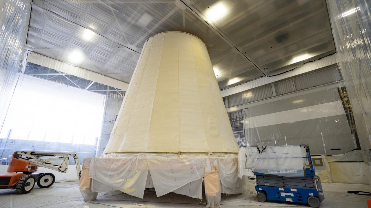
These photos show the launch vehicle stage adapter (LVSA) of NASA’s SLS (Space Launch System) rocket for Artemis III before technicians at NASA’s Marshall Space Flight Center in Huntsville, Alabama, applied the thermal protection system to it. Artemis III will land astronauts on the Moon to advance long-term lunar exploration and scientific discover and inspire the Artemis Generation. Teams at Marshall began applying the thermal protection system material in the spring of 2023. Unlike other parts of the SLS rocket, the thermal protection system material for the LVSA is applied entirely by hand using a spray gun. During application, the technicians use a thin measuring rod to gauge the proper thickness. Once the thermal protection system has cured, certain areas are sanded down to meet parameters. The entire process takes several months. The LVSA is fully manufactured at Marshall by NASA, lead contractor Teledyne Brown Engineering, and the Jacobs Space Group’s ESSCA contract. The LVSA for Artemis III is the last of its kind as future SLS rockets will transition to its next, more powerful Block 1B configuration beginning with Artemis IV. NASA is working to land the first woman and first person of color on the Moon under Artemis. SLS is part of NASA’s backbone for deep space exploration, along with the Orion spacecraft, advanced spacesuits and rovers, the Gateway in orbit around the Moon, and commercial human landing systems. SLS is the only rocket that can send Orion, astronauts, and supplies to the Moon in a single mission.
These photos show the launch vehicle stage adapter (LVSA) of NASA’s SLS (Space Launch System) rocket for Artemis III before technicians at NASA’s Marshall Space Flight Center in Huntsville, Alabama, applied the thermal protection system to it. Artemis III will land astronauts on the Moon to advance long-term lunar exploration and scientific discover and inspire the Artemis Generation. Teams at Marshall began applying the thermal protection system material in the spring of 2023. Unlike other parts of the SLS rocket, the thermal protection system material for the LVSA is applied entirely by hand using a spray gun. During application, the technicians use a thin measuring rod to gauge the proper thickness. Once the thermal protection system has cured, certain areas are sanded down to meet parameters. The entire process takes several months. The LVSA is fully manufactured at Marshall by NASA, lead contractor Teledyne Brown Engineering, and the Jacobs Space Group’s ESSCA contract. The LVSA for Artemis III is the last of its kind as future SLS rockets will transition to its next, more powerful Block 1B configuration beginning with Artemis IV. NASA is working to land the first woman and first person of color on the Moon under Artemis. SLS is part of NASA’s backbone for deep space exploration, along with the Orion spacecraft, advanced spacesuits and rovers, the Gateway in orbit around the Moon, and commercial human landing systems. SLS is the only rocket that can send Orion, astronauts, and supplies to the Moon in a single mission.
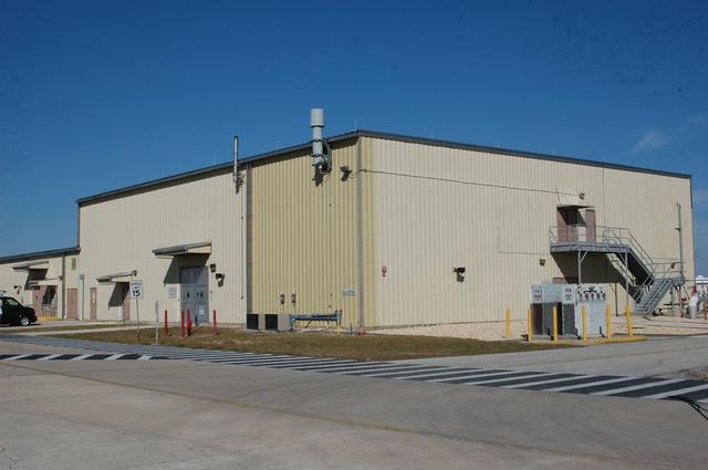
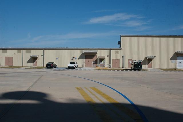
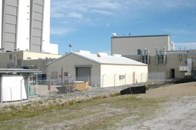
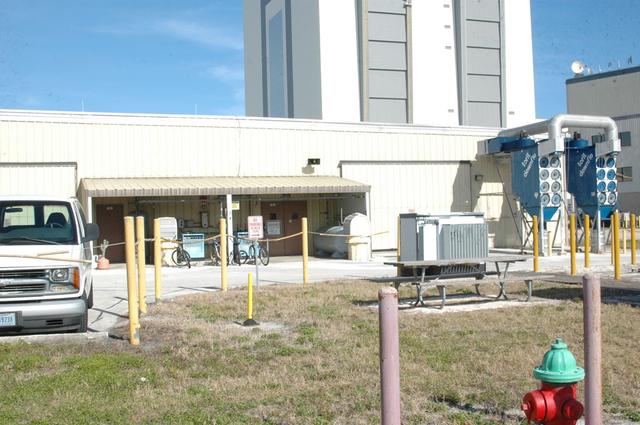
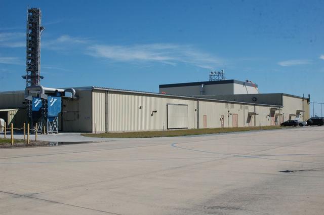
Exterior view of the Thermal Ptroctection System facility
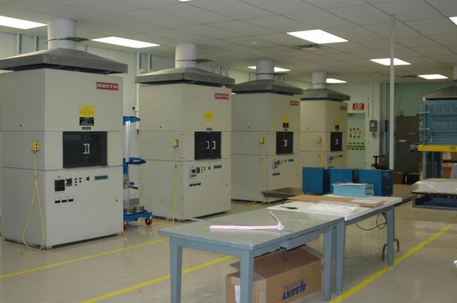
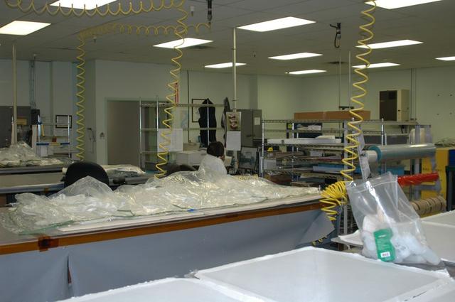
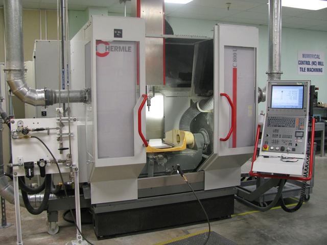
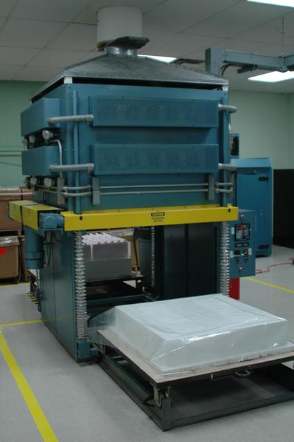
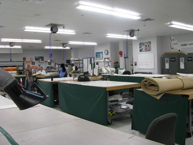
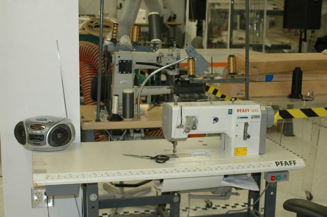
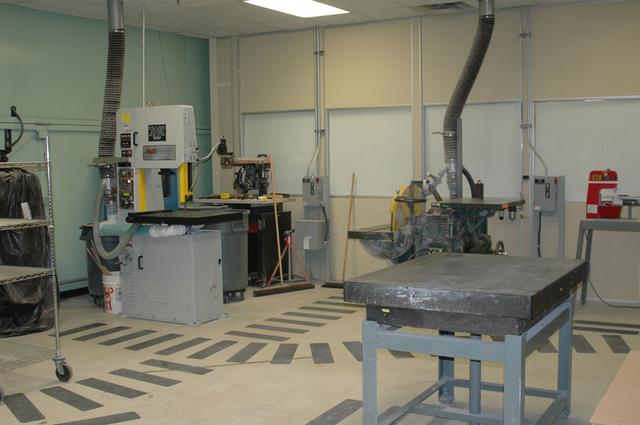
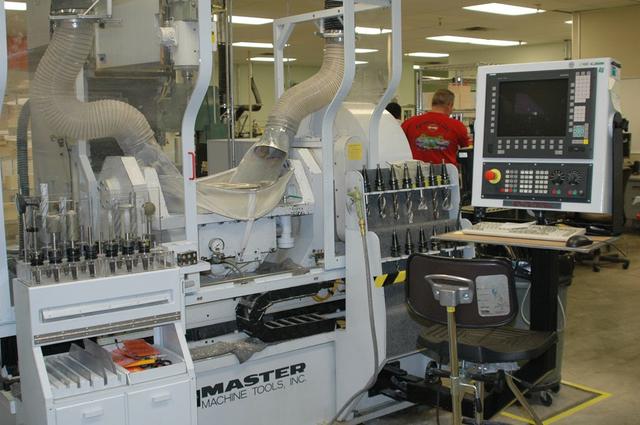
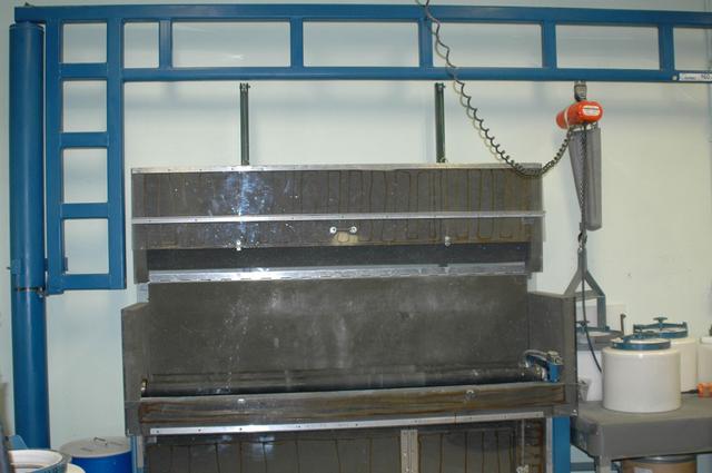
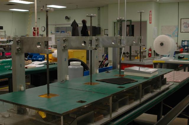
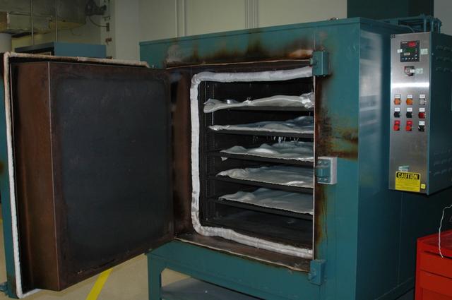
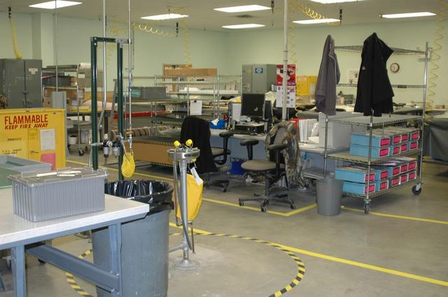
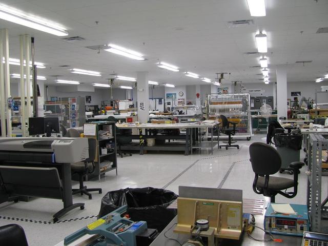
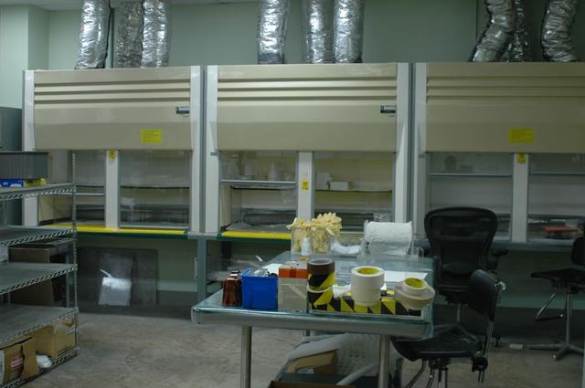
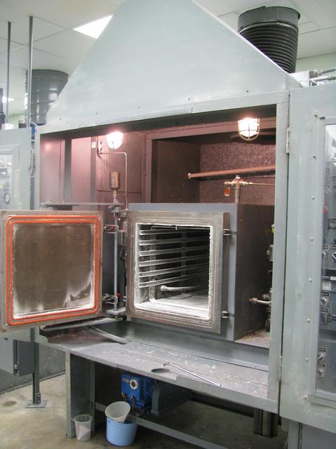
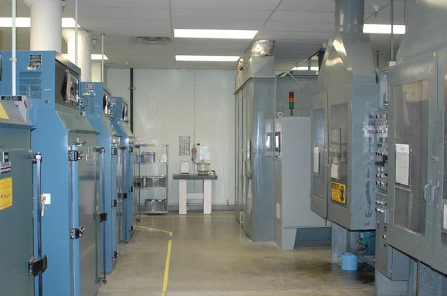
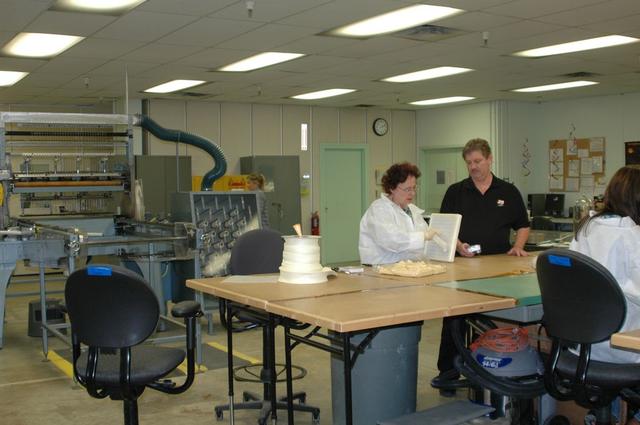
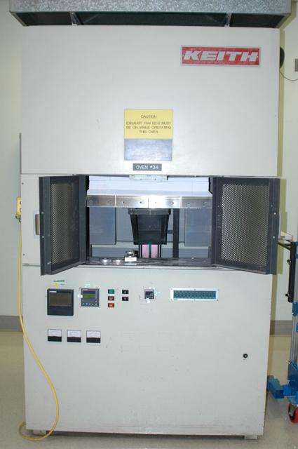
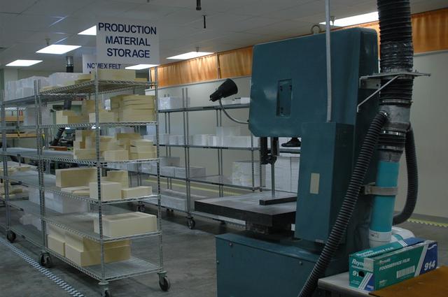
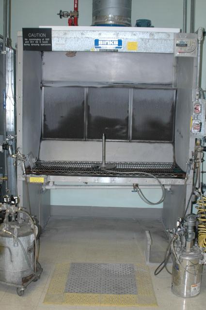
Interior view of the Thermal Ptroctection System facility
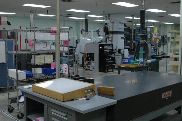
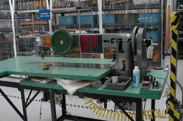
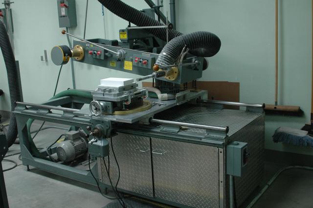
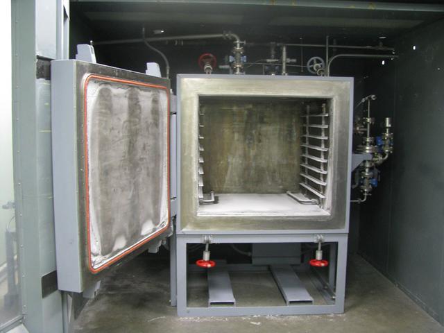
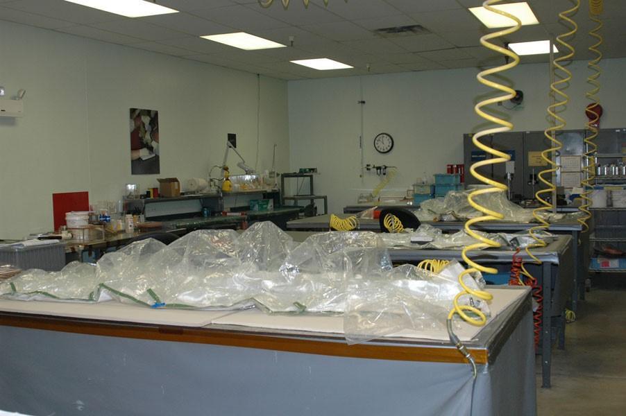
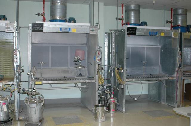
Interior view of the Thermal Ptroctection System facility
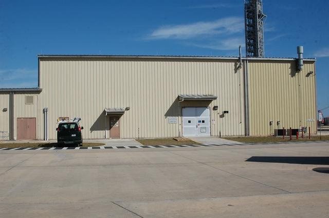
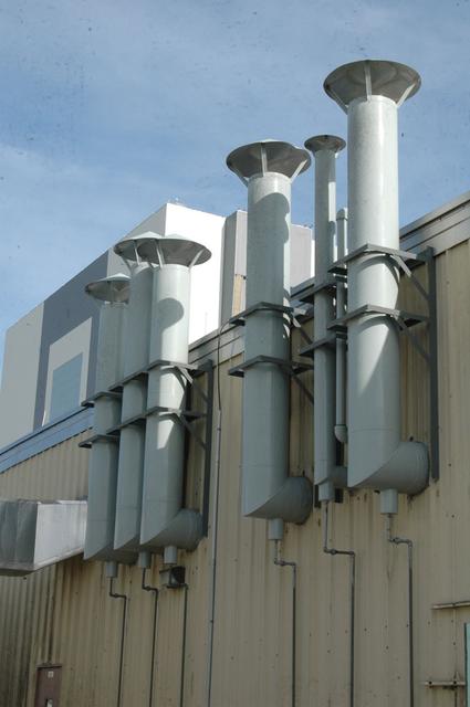
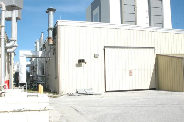
Exterior view of the Thermal Ptroctection System facility
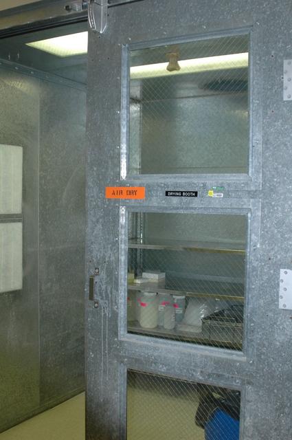
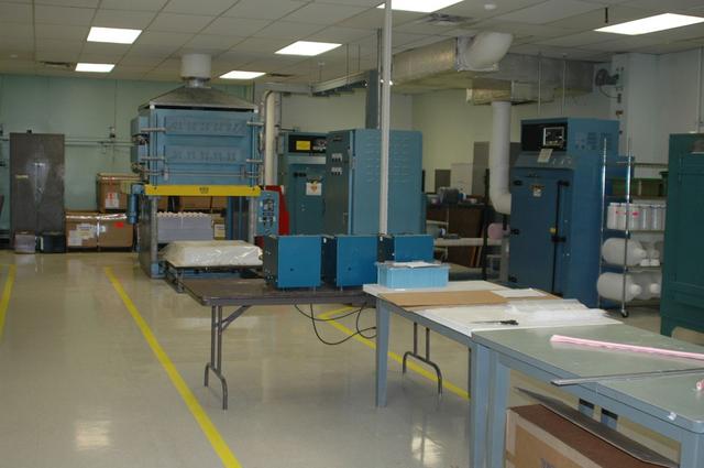
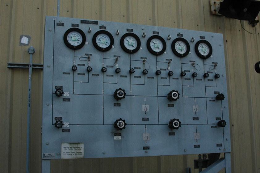
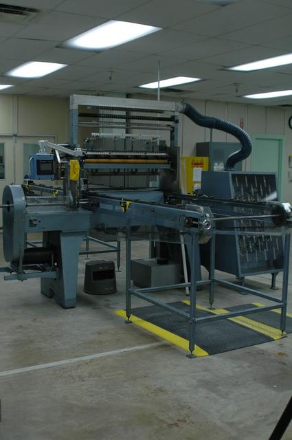
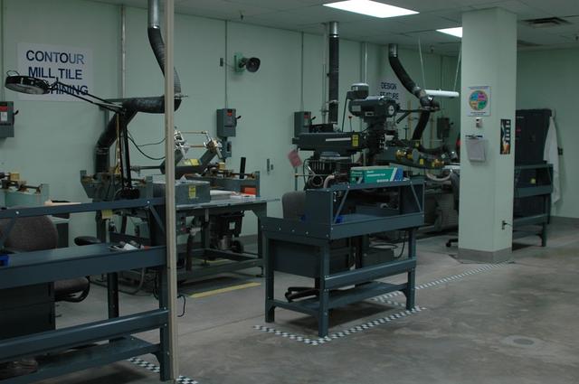
Interior view of the Thermal Ptroctection System facility
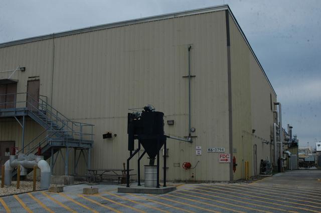
Exterior view of the Thermal Ptroctection System facility
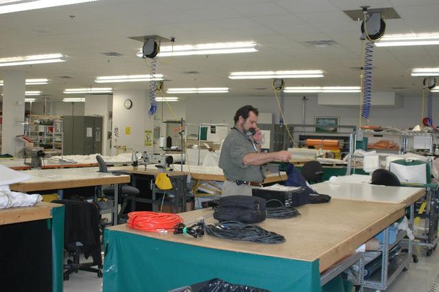
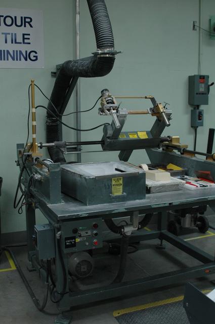
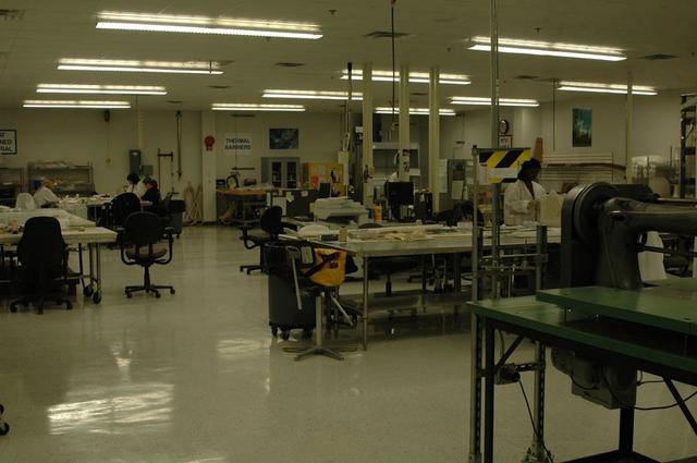
Interior view of the Thermal Ptroctection System facility
Interior view of the Thermal Ptroctection System facility
Interior view of the Thermal Ptroctection System facility
Interior view of the Thermal Ptroctection System facility
Interior view of the Thermal Ptroctection System facility
Interior view of the Thermal Ptroctection System facility
Interior view of the Thermal Ptroctection System facility
Interior view of the Thermal Ptroctection System facility
Exterior view of the Thermal Ptroctection System facility
Exterior view of the Thermal Ptroctection System facility
Interior view of the Thermal Ptroctection System facility
Exterior view of the Thermal Ptroctection System facility
Interior view of the Thermal Ptroctection System facility
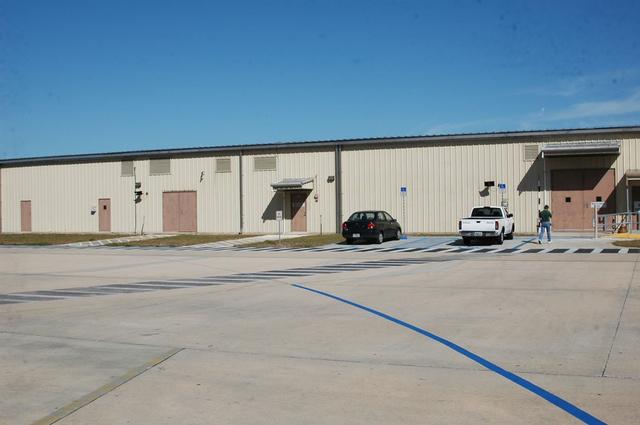
Exterior view of the Thermal Ptroctection System facility
Interior view of the Thermal Ptroctection System facility
Interior view of the Thermal Ptroctection System facility
Interior view of the Thermal Ptroctection System facility
Interior view of the Thermal Ptroctection System facility
Interior view of the Thermal Ptroctection System facility
Interior view of the Thermal Ptroctection System facility
Interior view of the Thermal Ptroctection System facility
Interior view of the Thermal Ptroctection System facility
Exterior view of the Thermal Ptroctection System facility
Interior view of the Thermal Ptroctection System facility
Interior view of the Thermal Ptroctection System facility
Interior view of the Thermal Ptroctection System facility

Interior view of the Thermal Ptroctection System facility
Interior view of the Thermal Ptroctection System facility
Interior view of the Thermal Ptroctection System facility
Interior view of the Thermal Ptroctection System facility
Exterior view of the Thermal Ptroctection System facility
Interior view of the Thermal Ptroctection System facility
Interior view of the Thermal Ptroctection System facility
Interior view of the Thermal Ptroctection System facility
Interior view of the Thermal Ptroctection System facility
Interior view of the Thermal Ptroctection System facility
Interior view of the Thermal Ptroctection System facility
Interior view of the Thermal Ptroctection System facility
Exterior view of the Thermal Ptroctection System facility
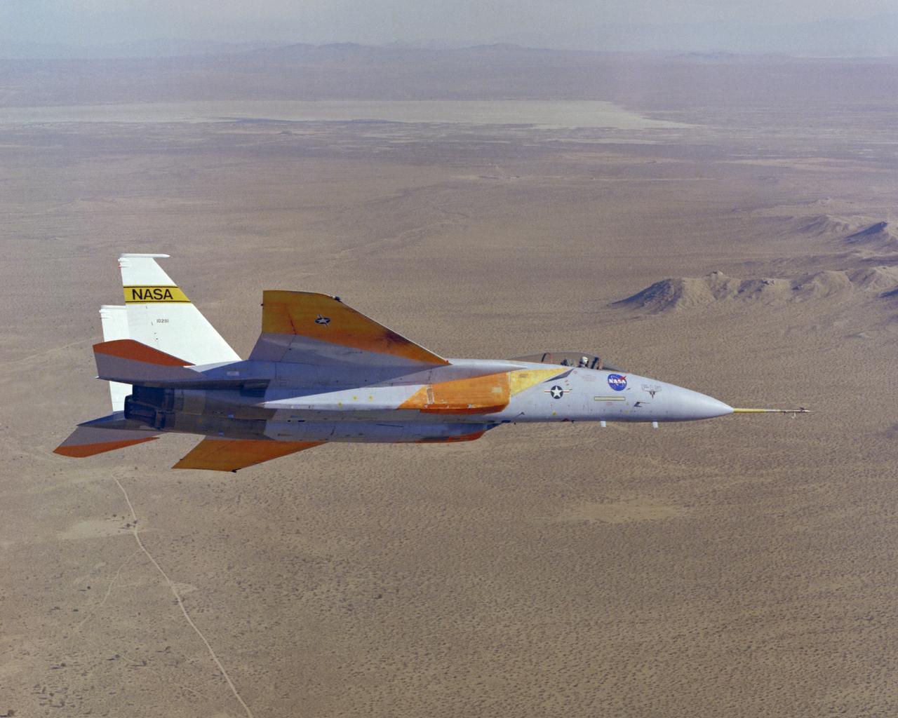
The number two F-15A (Serial #71-0281) was obtained by NASA from the U.S. Air Force in 1976 and was used for more than 25 advanced research projects involving aerodynamics, performance, propulsion control, control integration, instrumentation development, human factors, and flight test techniques. Included in these projects was its role as a testbed to evaluate aerodynamic pressures on Space Shuttle thermal protection tiles at specific altitudes and speeds.
Technicians at NASA’s Michoud Assembly Facility move the intertank of NASA’s Space Launch System rocket for Artemis III to Cell G to await application of the thermal protection system. Thermal protection systems protect space vehicles from aerodynamic heating during entry to planet atmosphere and re-entry to earth atmosphere.

In-flight photo of the NASA F-15B used in tests of the X-33 Thermal Protection System (TPS) materials. Flying at subsonic speeds, the F-15B tests measured the air loads on the proposed X-33 protective materials. In contrast, shock loads testing investigated the local impact of the supersonic shock wave itself on the TPS materials. Similar tests had been done in 1985 for the space shuttle tiles, using an F-104 aircraft.
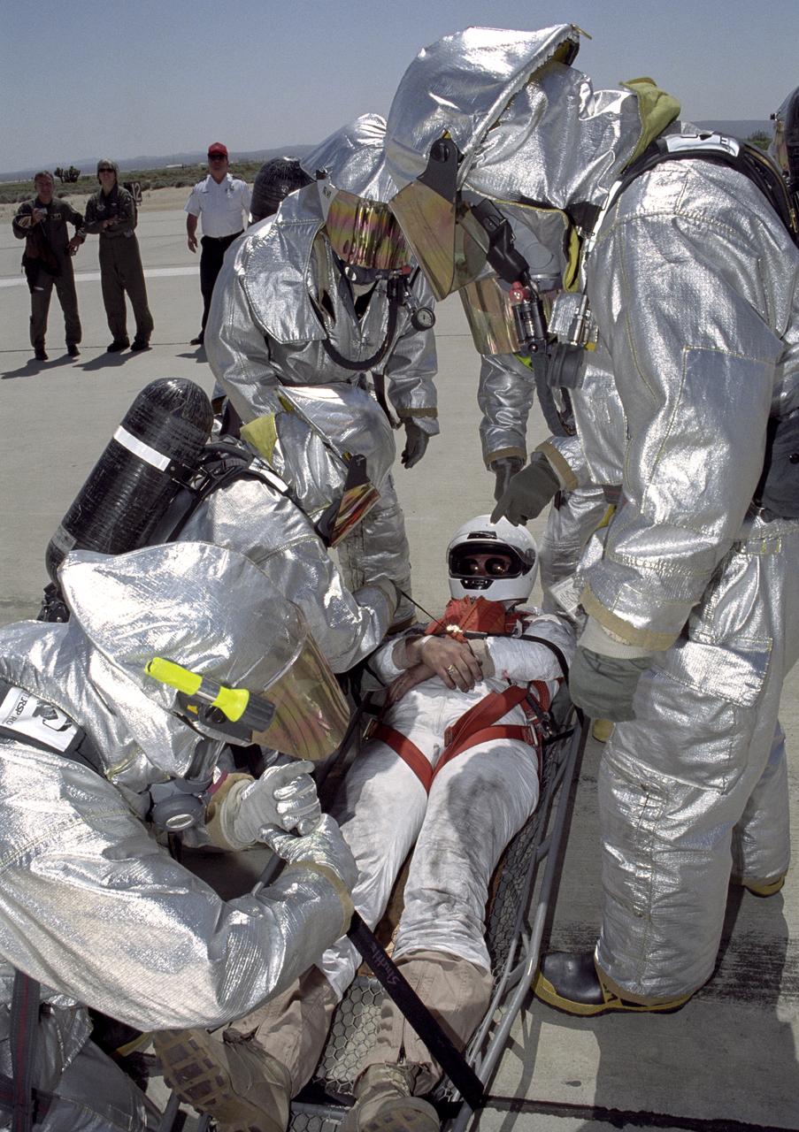
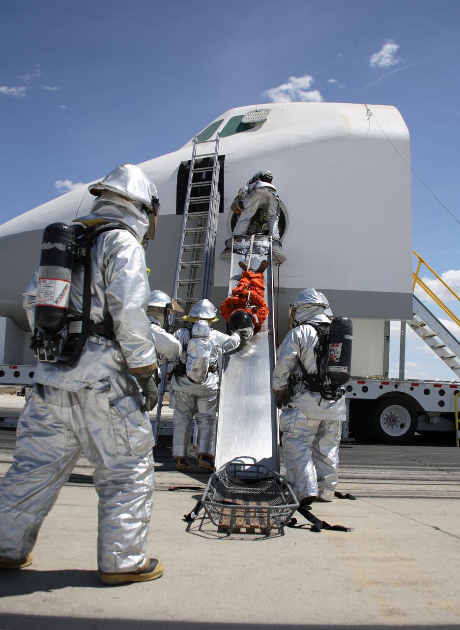
Clad in full thermal protection suits, Air Force fire-rescue crews strap a stand-in "astronaut" into a litter during a Space Shuttle rescue training exercise at Edwards AFB.
KENNEDY SPACE CENTER, FLA. - In the Orbiter Processing Facility, KSC employee Nadine Phillips prepares an area on the orbiter Discovery for blanket installation. The blankets are part of the Orbiter Thermal Protection System, thermal shields to protect against temperatures as high as 3,000° Fahrenheit, which are produced during descent for landing. Discovery is scheduled to fly on mission STS-121 to the International Space Station.
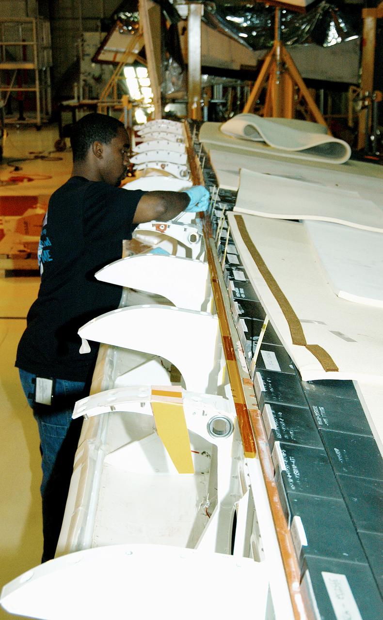
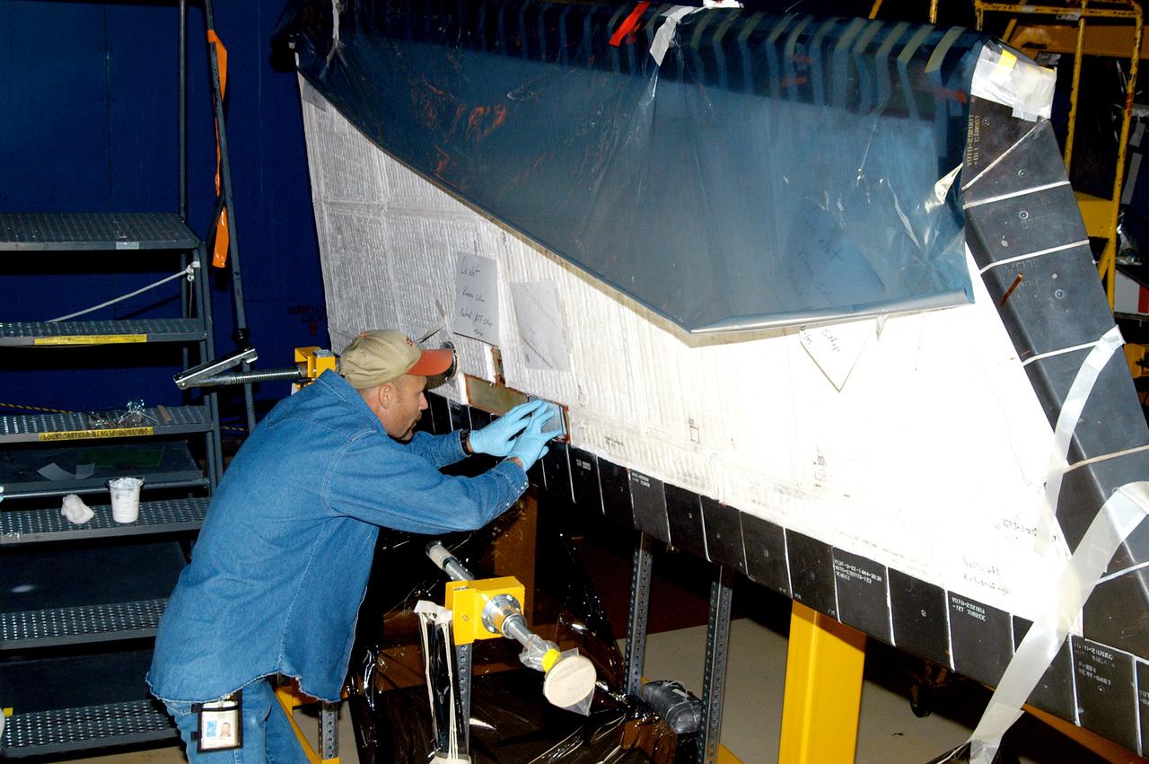
KENNEDY SPACE CENTER, FLA. - In the Orbiter Processing Facility, KSC employee Duane Williams prepares the blanket insulation to be installed on the body flap on orbiter Discovery. The blankets are part of the Orbiter Thermal Protection System, thermal shields to protect against temperatures as high as 3,000° Fahrenheit, which are produced during descent for landing. Discovery is scheduled to fly on mission STS-121 to the International Space Station.
KENNEDY SPACE CENTER, FLA. - In the Orbiter Processing Facility, KSC employee Duane Williams prepares the blanket insulation to be installed on the body flap on orbiter Discovery. The blankets are part of the Orbiter Thermal Protection System, thermal shields to protect against temperatures as high as 3,000° Fahrenheit, which are produced during descent for landing. Discovery is scheduled to fly on mission STS-121 to the International Space Station.
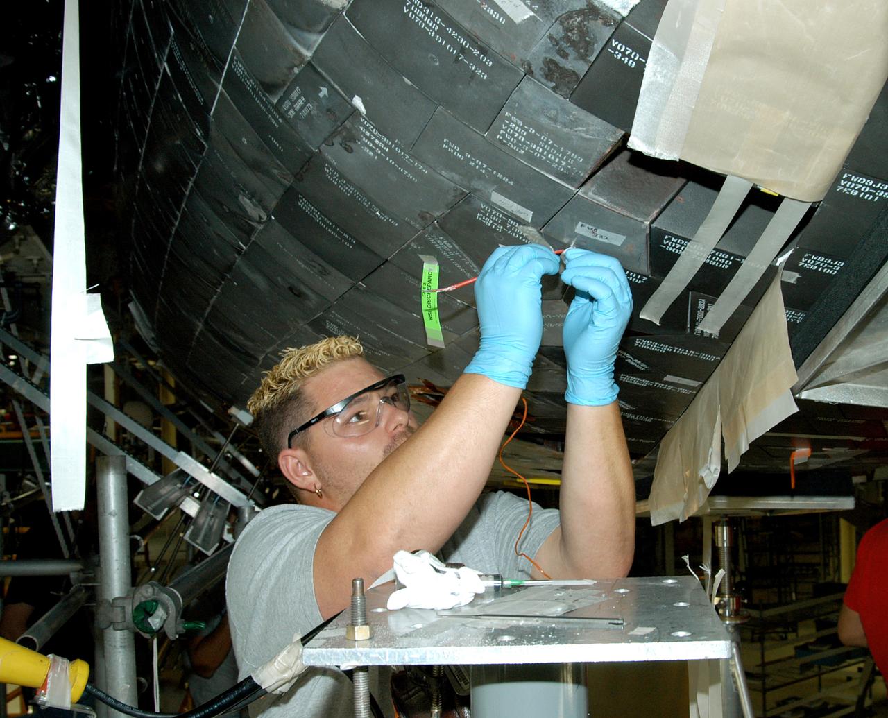
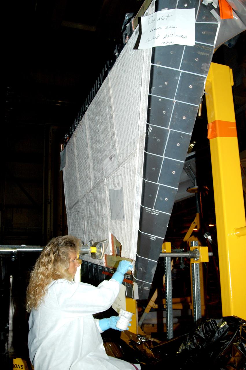
KENNEDY SPACE CENTER, FLA. - In the Orbiter Processing Facility, KSC employee Chris Moore repairs tile on the forward area of the orbiter Discovery. The vehicle has undergone Orbiter Major Modifications in the past year, which includes tile check and repair. The tiles are part of the Orbiter Thermal Protection System, thermal shields to protect against temperatures as high as 3,000° Fahrenheit, which are produced during descent for landing. Discovery is scheduled to fly on mission STS-121 to the International Space Station.
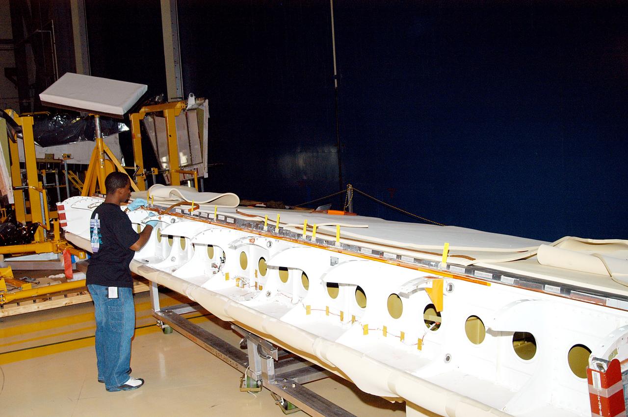
KENNEDY SPACE CENTER, FLA. - In the Orbiter Processing Facility, KSC employee Joel Smith prepares an area on the orbiter Discovery for blanket installation. The blankets are part of the Orbiter Thermal Protection System, thermal shields to protect against temperatures as high as 3,000° Fahrenheit, which are produced during descent for landing. Discovery is scheduled to fly on mission STS-121 to the International Space Station.
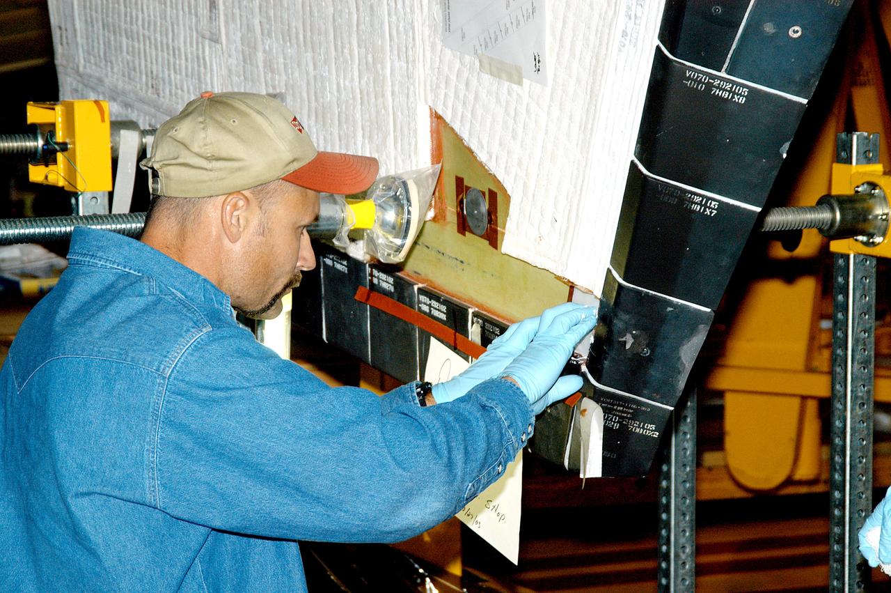
KENNEDY SPACE CENTER, FLA. - In the Orbiter Processing Facility, KSC employee Joel Smith prepares an area on the orbiter Discovery for blanket installation. The blankets are part of the Orbiter Thermal Protection System, thermal shields to protect against temperatures as high as 3,000° Fahrenheit, which are produced during descent for landing. Discovery is scheduled to fly on mission STS-121 to the International Space Station.
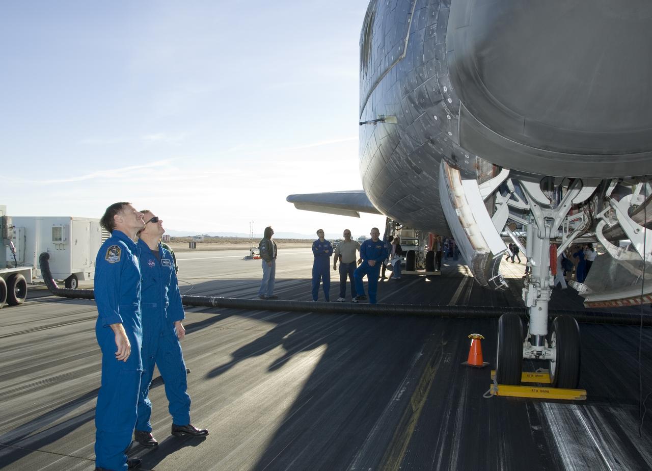
STS-126 commander Chris Ferguson and pilot Eric Boe examine shuttle Endeavour's thermal protection system following the STS-126 landing at Edwards AFB Nov. 30.
Clad in thermal protection suits, fire/rescue crew aid a volunteer "Injured astronaut" to a head-first ride down the exit slide from the shuttle cabin mockup. (USAF photo # 070505-F-1287F-132)

A close up of the Flight Test Fixture II, mounted on the underside of the F-15B Aerodynamic Flight Facility aircraft. The Thermal Protection System (TPS) samples, which included metallic Inconel tiles, soft Advanced Flexible Reusable Surface Insulation tiles, and sealing materials, were attached to the forward-left side position of the test fixture. In-flight video from the aircraft's on-board video system, as well as chase aircraft photos and video footage, documented the condition of the TPS during flights. Surface pressures over the TPS was measured by thermocouples contained in instrumentation "islands," to document shear and shock loads.
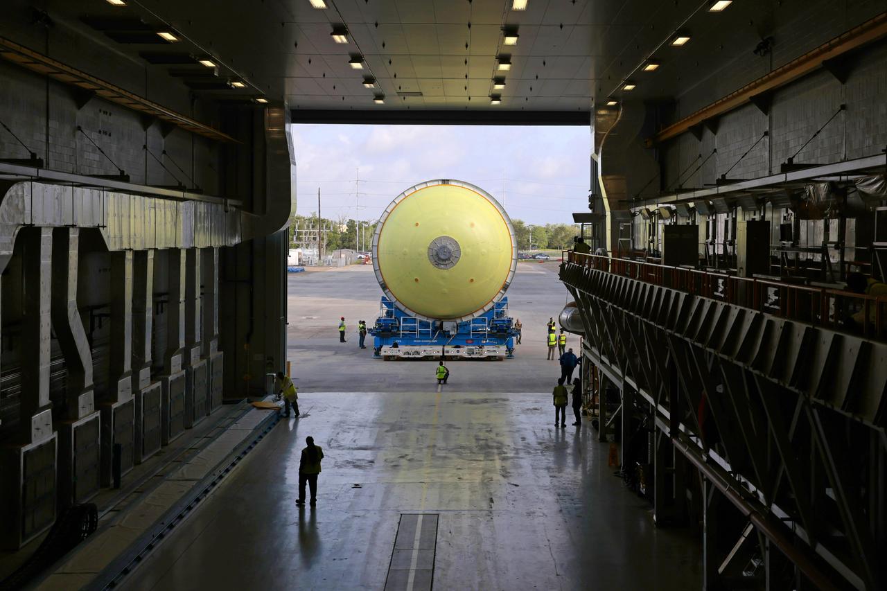
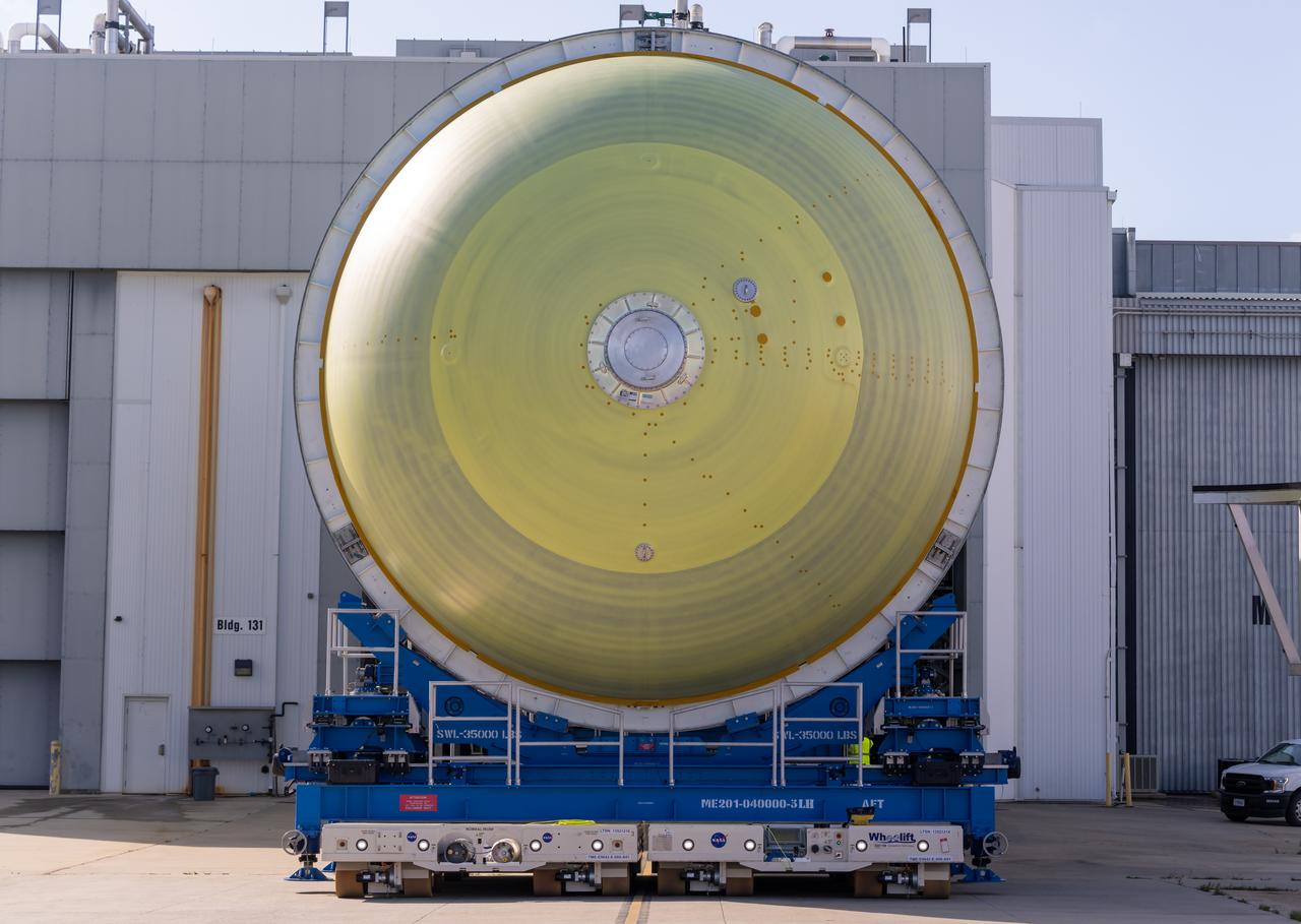
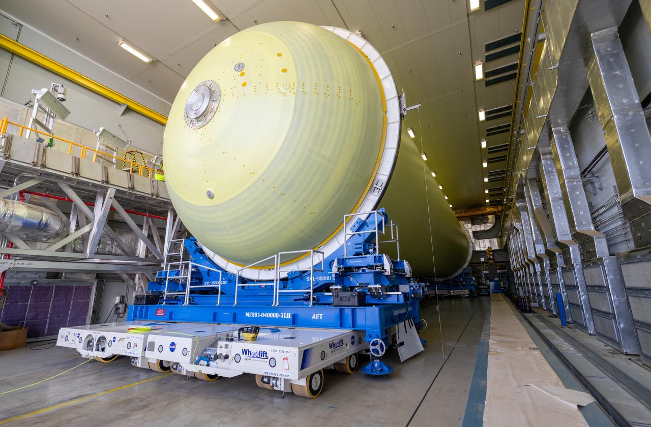
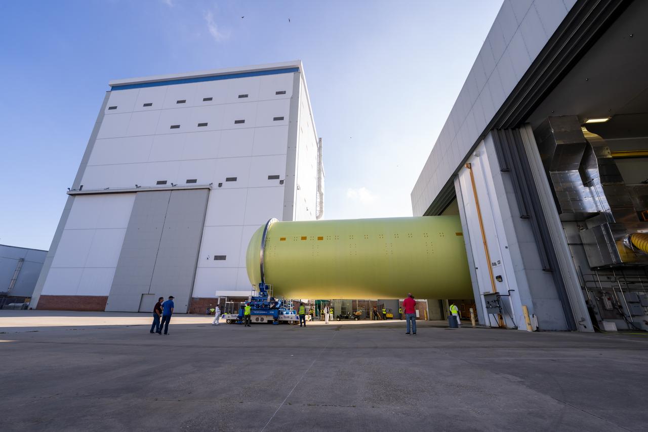
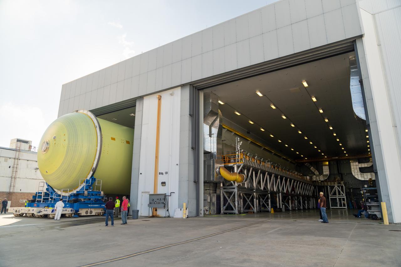
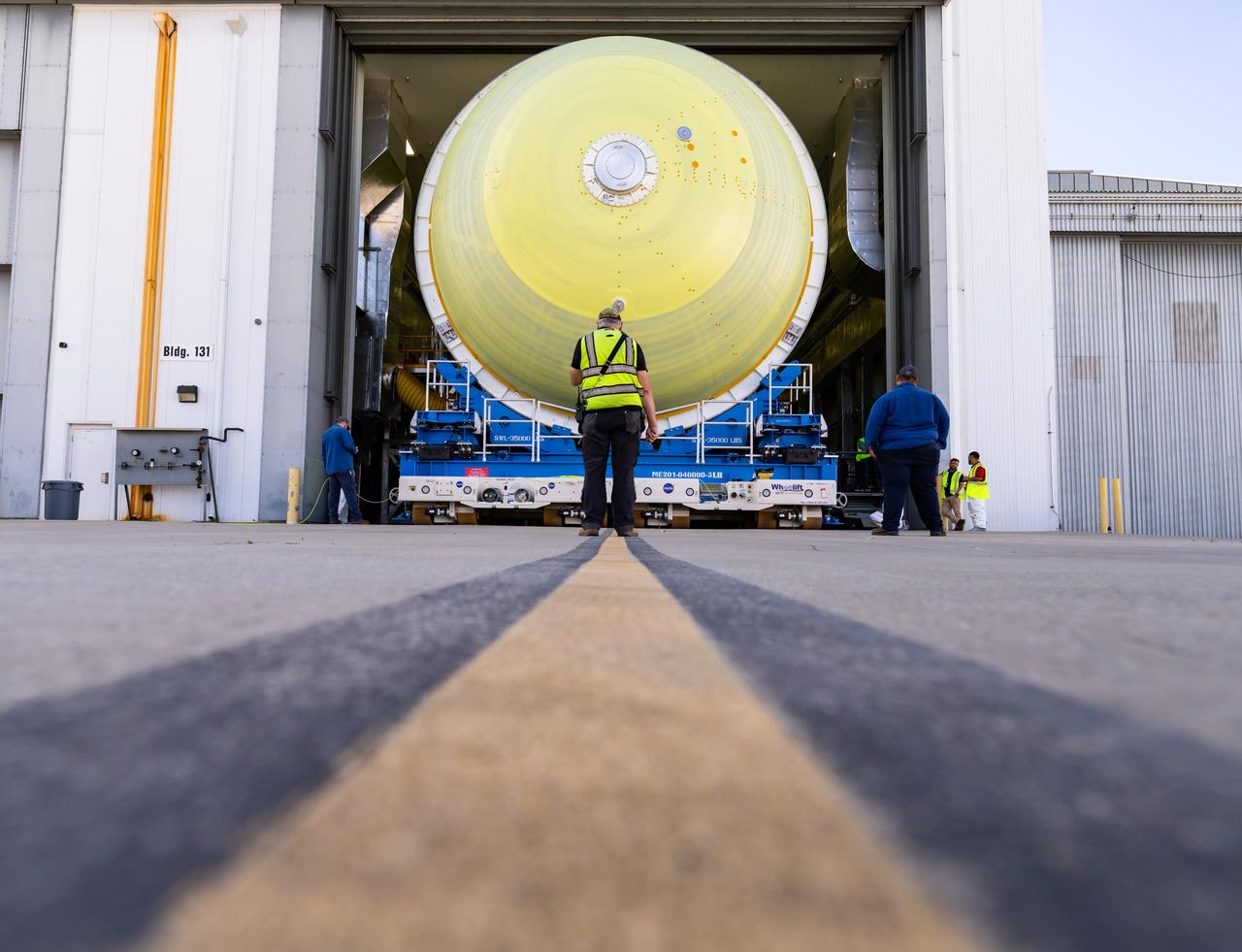
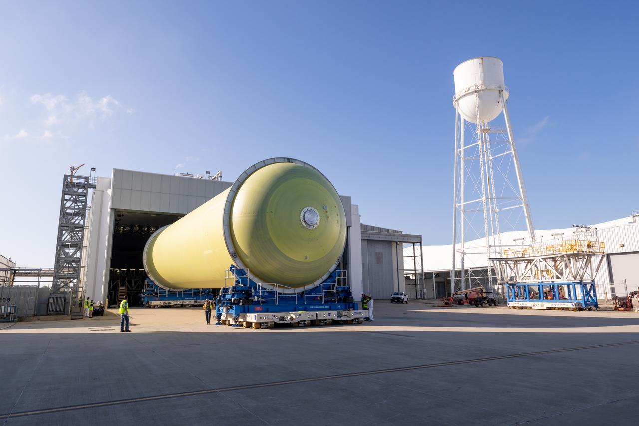
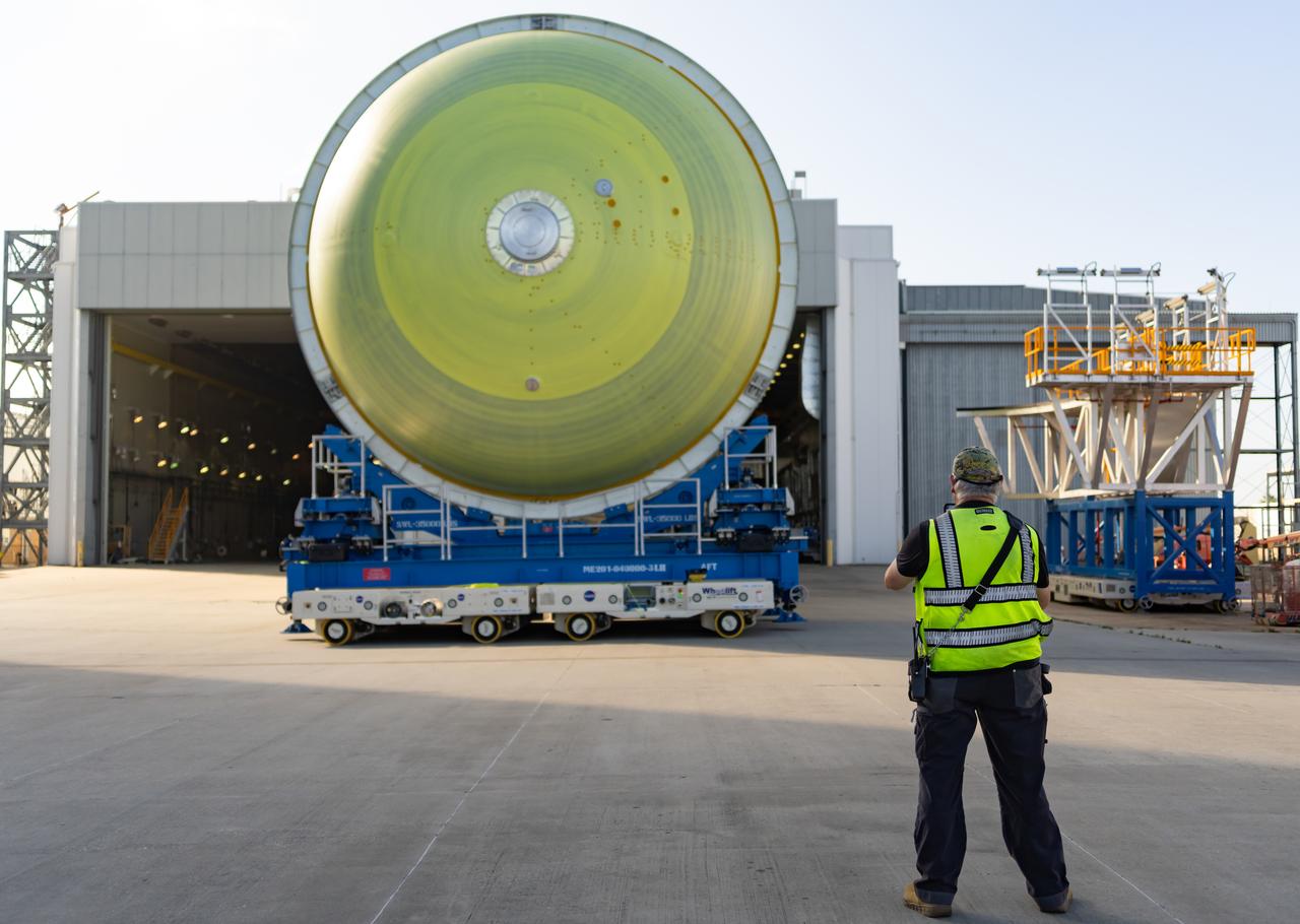
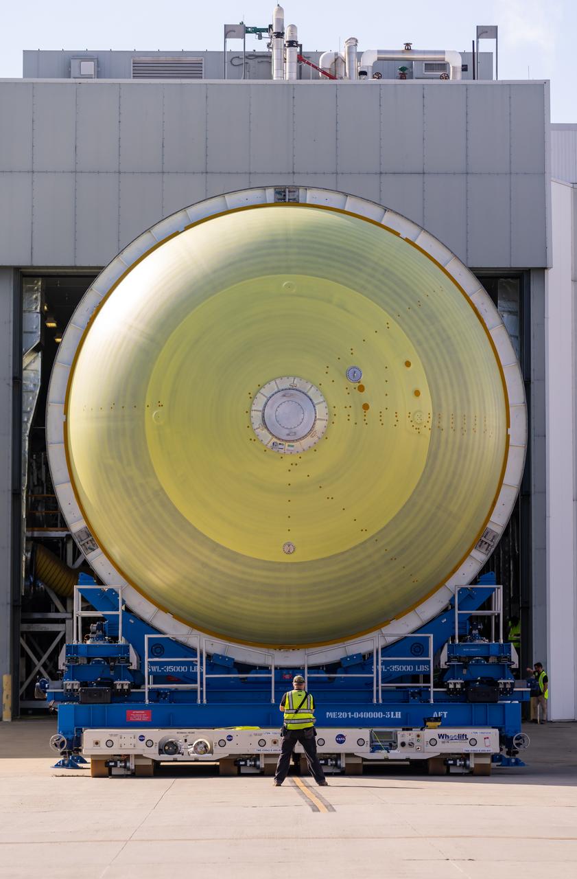
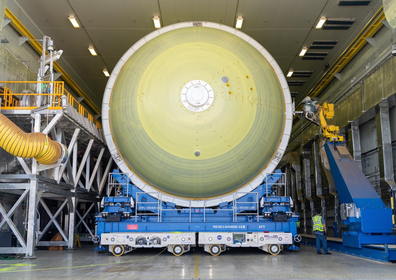
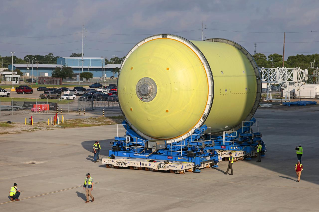
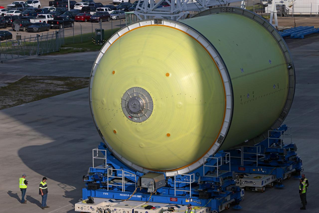
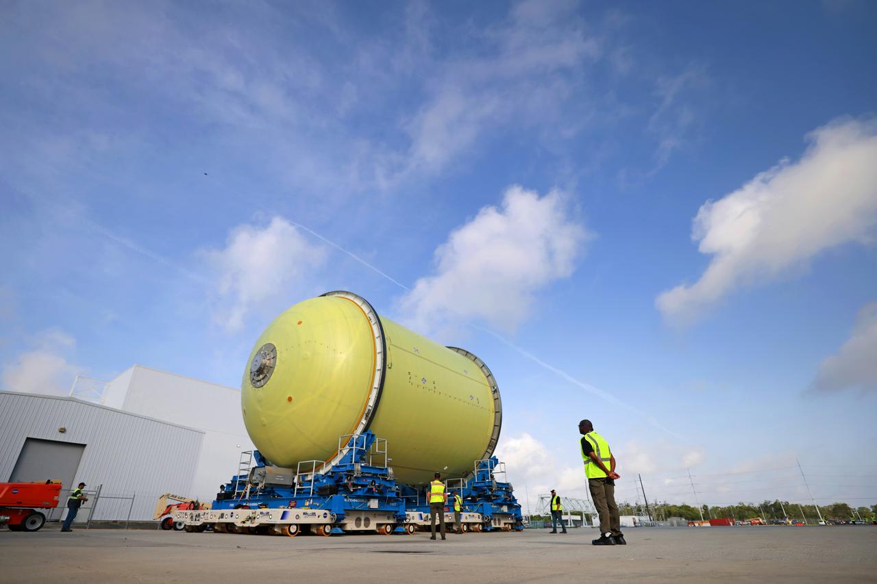
Teams move a liquid oxygen tank from the main factory at NASA’s Michoud Assembly Facility in New Orleans to a nearby production cell on April 25, 2025. Designated for the core stage of NASA’s SLS (Space Launch System) rocket for NASA’s Artemis III mission, the tank will now undergo application of its thermal protection system through an automated process. The propellant tank is one of five major elements that make up the 212-foot-tall rocket stage. The core stage, along with its four RS-25 engines, produce more than two million pounds of thrust to help launch NASA’s Orion spacecraft, astronauts, and supplies beyond Earth’s orbit and to the lunar surface for Artemis. Image credit: NASA/Michael DeMocker
Teams move a liquid oxygen tank from the main factory at NASA’s Michoud Assembly Facility in New Orleans to a nearby production cell on April 25, 2025. Designated for the core stage of NASA’s SLS (Space Launch System) rocket for NASA’s Artemis III mission, the tank will now undergo application of its thermal protection system through an automated process. The propellant tank is one of five major elements that make up the 212-foot-tall rocket stage. The core stage, along with its four RS-25 engines, produce more than two million pounds of thrust to help launch NASA’s Orion spacecraft, astronauts, and supplies beyond Earth’s orbit and to the lunar surface for Artemis. Image credit: NASA/Michael DeMocker
Teams move a liquid oxygen tank from the main factory at NASA’s Michoud Assembly Facility in New Orleans to a nearby production cell on April 25, 2025. Designated for the core stage of NASA’s SLS (Space Launch System) rocket for NASA’s Artemis III mission, the tank will now undergo application of its thermal protection system through an automated process. The propellant tank is one of five major elements that make up the 212-foot-tall rocket stage. The core stage, along with its four RS-25 engines, produce more than two million pounds of thrust to help launch NASA’s Orion spacecraft, astronauts, and supplies beyond Earth’s orbit and to the lunar surface for Artemis. Image credit: NASA/Michael DeMocker

Teams move a liquid oxygen tank from the main factory at NASA’s Michoud Assembly Facility in New Orleans to a nearby production cell on April 25, 2025. Designated for the core stage of NASA’s SLS (Space Launch System) rocket for NASA’s Artemis III mission, the tank will now undergo application of its thermal protection system through an automated process. The propellant tank is one of five major elements that make up the 212-foot-tall rocket stage. The core stage, along with its four RS-25 engines, produce more than two million pounds of thrust to help launch NASA’s Orion spacecraft, astronauts, and supplies beyond Earth’s orbit and to the lunar surface for Artemis. Image credit: NASA/Michael DeMocker

Teams move a liquid oxygen tank from the main factory at NASA’s Michoud Assembly Facility in New Orleans to a nearby production cell on April 25, 2025. Designated for the core stage of NASA’s SLS (Space Launch System) rocket for NASA’s Artemis III mission, the tank will now undergo application of its thermal protection system through an automated process. The propellant tank is one of five major elements that make up the 212-foot-tall rocket stage. The core stage, along with its four RS-25 engines, produce more than two million pounds of thrust to help launch NASA’s Orion spacecraft, astronauts, and supplies beyond Earth’s orbit and to the lunar surface for Artemis. Image credit: NASA/Michael DeMocker
Teams move a liquid oxygen tank from the main factory at NASA’s Michoud Assembly Facility in New Orleans to a nearby production cell on April 25, 2025. Designated for the core stage of NASA’s SLS (Space Launch System) rocket for NASA’s Artemis III mission, the tank will now undergo application of its thermal protection system through an automated process. The propellant tank is one of five major elements that make up the 212-foot-tall rocket stage. The core stage, along with its four RS-25 engines, produce more than two million pounds of thrust to help launch NASA’s Orion spacecraft, astronauts, and supplies beyond Earth’s orbit and to the lunar surface for Artemis. Image credit: NASA/Michael DeMocker
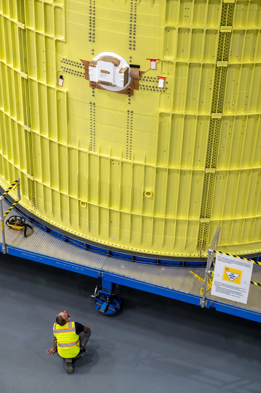
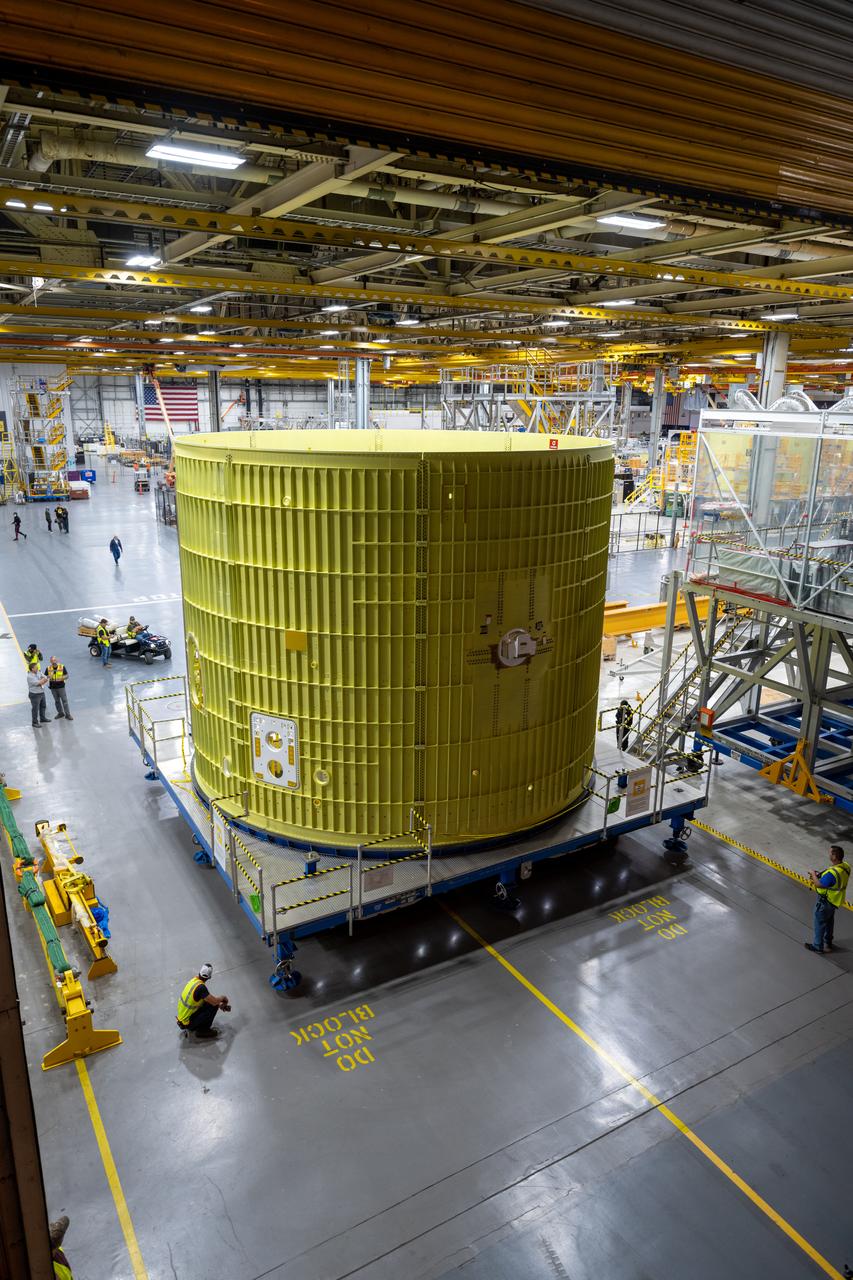
Technicians at NASA’s Michoud Assembly Facility move the intertank of NASA’s Space Launch System rocket for Artemis III to Cell G to await application of the thermal protection system. Thermal protection systems protect space vehicles from aerodynamic heating during entry to planet atmosphere and re-entry to earth atmosphere. The intertank lays between the liquid hydrogen tank and liquid oxygen tank. Together with the engine section and the forward skirt, they comprise the SLS core stage. The liquid hydrogen tank and liquid oxygen tank hold 733,000 gallons of propellant to power the stage’s four RS-25 engines needed for liftoff and Artemis missions to the Moon and future missions to Mars.
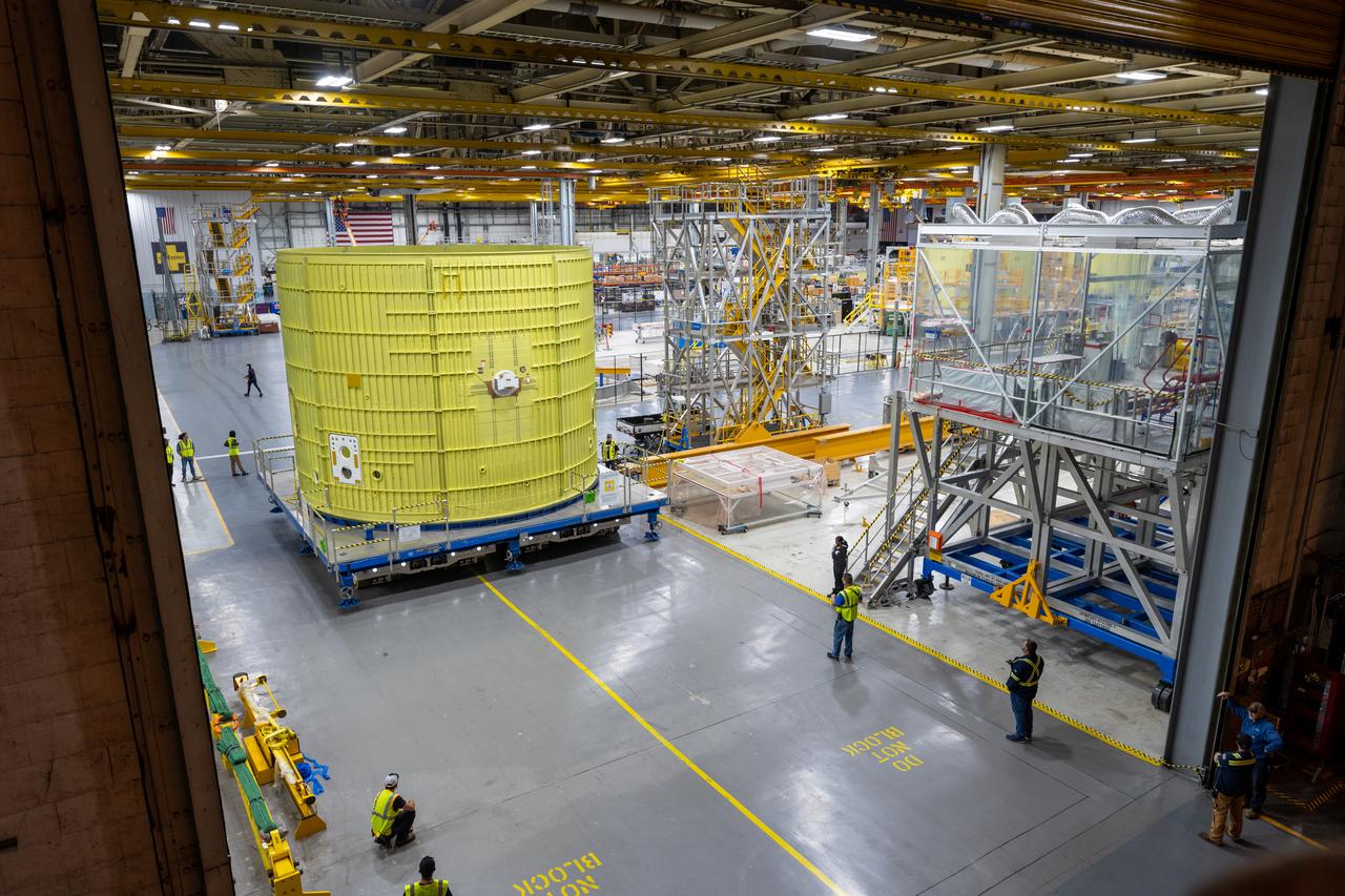
Technicians at NASA’s Michoud Assembly Facility move the intertank of NASA’s Space Launch System rocket for Artemis III to Cell G to await application of the thermal protection system. Thermal protection systems protect space vehicles from aerodynamic heating during entry to planet atmosphere and re-entry to earth atmosphere. The intertank lays between the liquid hydrogen tank and liquid oxygen tank. Together with the engine section and the forward skirt, they comprise the SLS core stage. The liquid hydrogen tank and liquid oxygen tank hold 733,000 gallons of propellant to power the stage’s four RS-25 engines needed for liftoff and Artemis missions to the Moon and future missions to Mars.
Technicians at NASA’s Michoud Assembly Facility move the intertank of NASA’s Space Launch System rocket for Artemis III to Cell G to await application of the thermal protection system. Thermal protection systems protect space vehicles from aerodynamic heating during entry to planet atmosphere and re-entry to earth atmosphere. The intertank lays between the liquid hydrogen tank and liquid oxygen tank. Together with the engine section and the forward skirt, they comprise the SLS core stage. The liquid hydrogen tank and liquid oxygen tank hold 733,000 gallons of propellant to power the stage’s four RS-25 engines needed for liftoff and Artemis missions to the Moon and future missions to Mars.
Technicians at NASA’s Michoud Assembly Facility move the intertank of NASA’s Space Launch System rocket for Artemis III to Cell G to await application of the thermal protection system. Thermal protection systems protect space vehicles from aerodynamic heating during entry to planet atmosphere and re-entry to earth atmosphere. The intertank lays between the liquid hydrogen tank and liquid oxygen tank. Together with the engine section and the forward skirt, they comprise the SLS core stage. The liquid hydrogen tank and liquid oxygen tank hold 733,000 gallons of propellant to power the stage’s four RS-25 engines needed for liftoff and Artemis missions to the Moon and future missions to Mars.