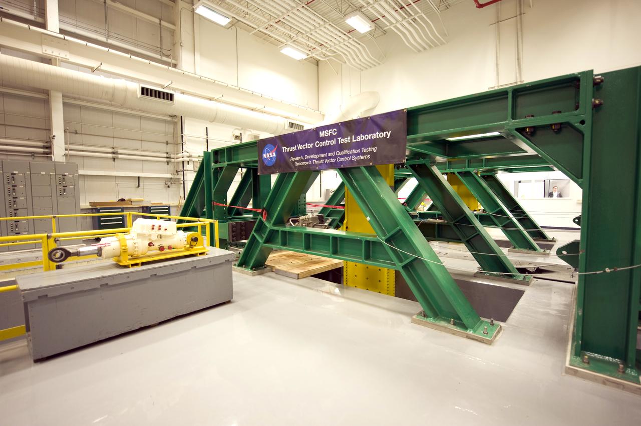
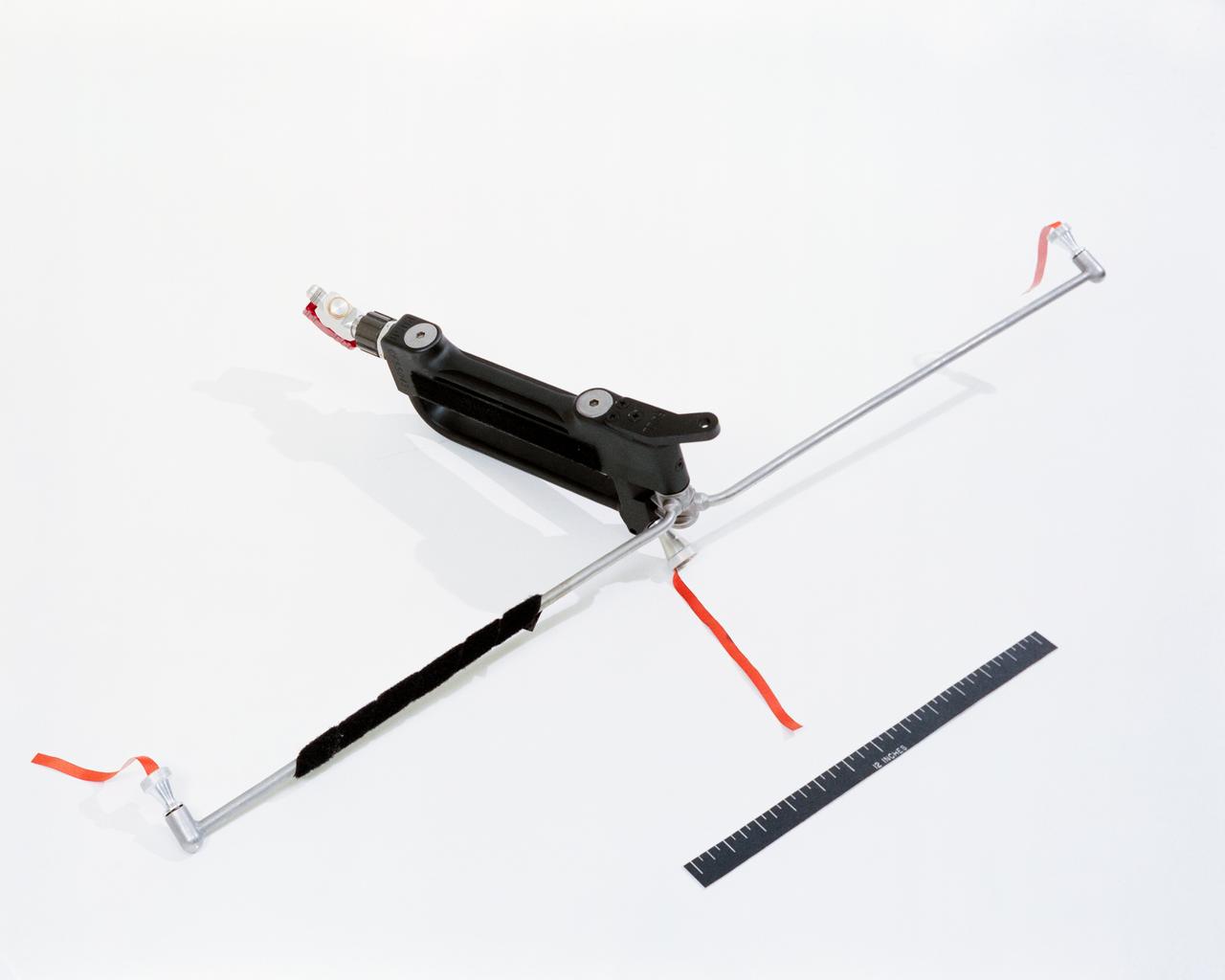
THRUST VECTOR CONTROL (TVC) TEST LAB INERTIAL LOAD SIMULATORS
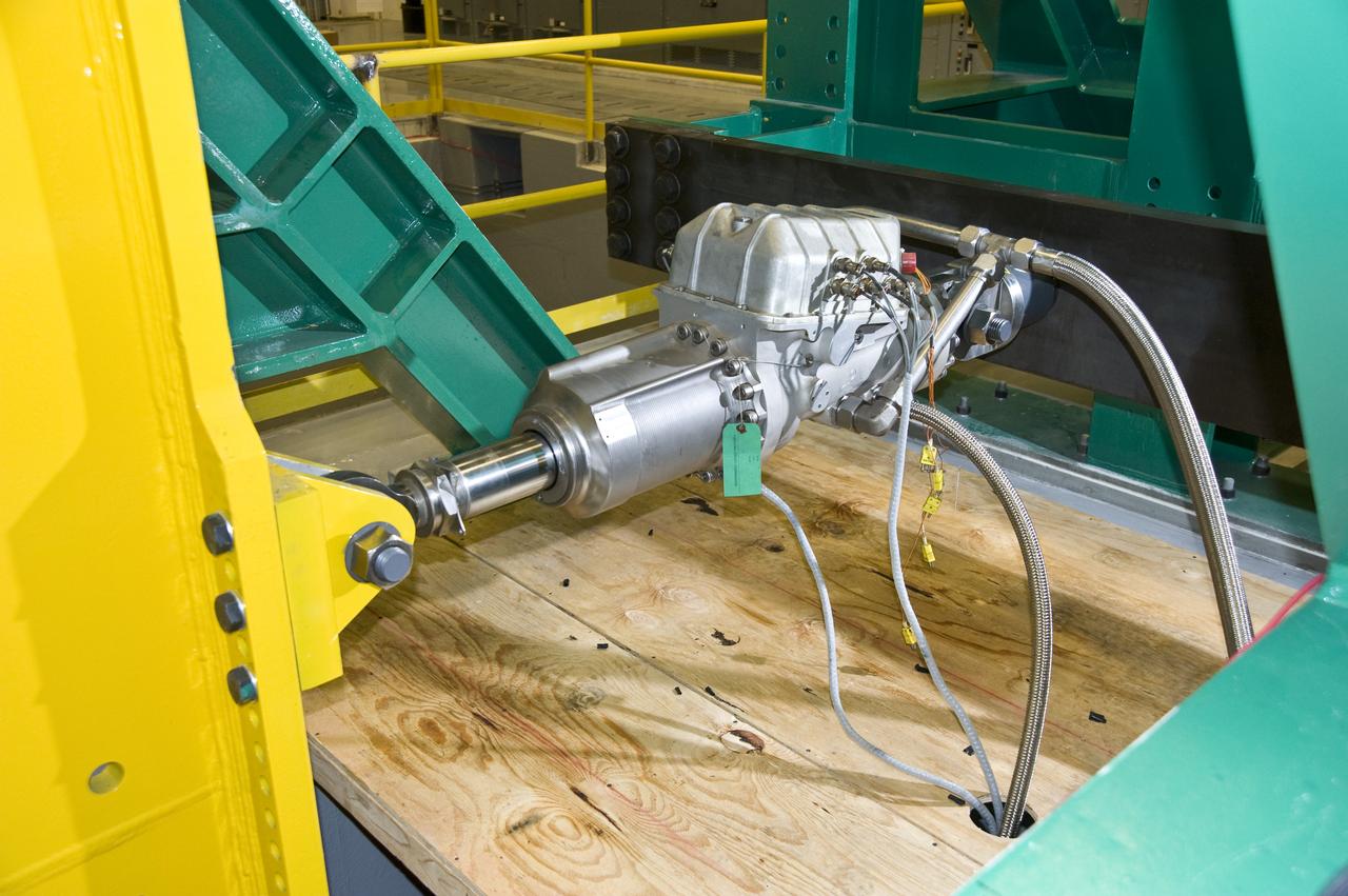
THRUST VECTOR CONTROL (TVC) TEST LAB TEST ACTUATOR
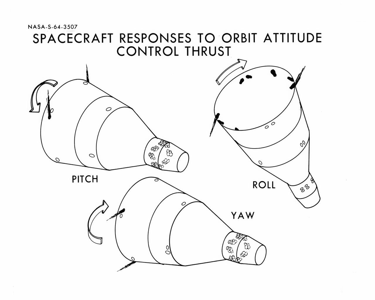
S64-03507 (1964) --- Diagrams shows Gemini spacecraft responses to orbital attitude systems's thrusters. Firing of appropriate combination of the thrusters cause pitch, roll and yaw.
Testing of the Ascent Thrust Vector Control System in support of the Ares 1-X program at the Marshall Space Flight Center in Huntsville, Alabama. This image is extracted from a high definition video file and is the highest resolution available
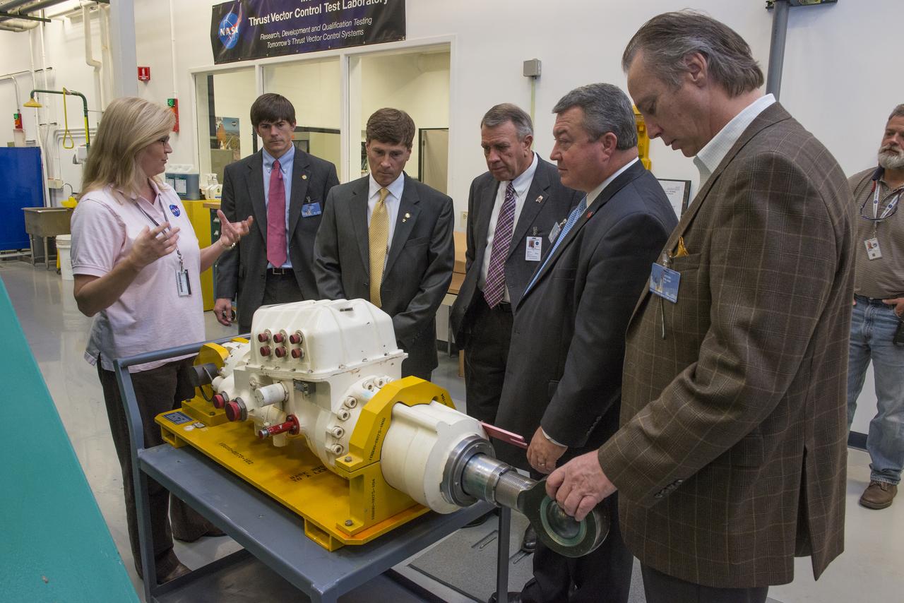
LISA BATES PROVIDES AN OVERVIEW OF THRUST VECTOR CONTROL TO STATE SENATOR BILL HOLTZCLAW, REPRESENTATIVE MAC MCCUTCHEON, GREG CANFIELD OF THE ALABAMA DEPARTMENT OF COMMERCE, GOVERNOR BENTLEY’S CHIEF OF STAFF, DAVID PERRY, AND LT. GOVERNOR STRANGES CHIEF OF STAFF, STEVE PELHAM.
LISA BATES PROVIDES AN OVERVIEW OF THRUST VECTOR CONTROL TO STATE SENATOR BILL HOLTZCLAW, REPRESENTATIVE MAC MCCUTCHEON, GREG CANFIELD OF THE ALABAMA DEPARTMENT OF COMMERCE, GOVERNOR BENTLEY’S CHIEF OF STAFF, DAVID PERRY, AND LT. GOVERNOR STRANGES CHIEF OF STAFF, STEVE PELHAM
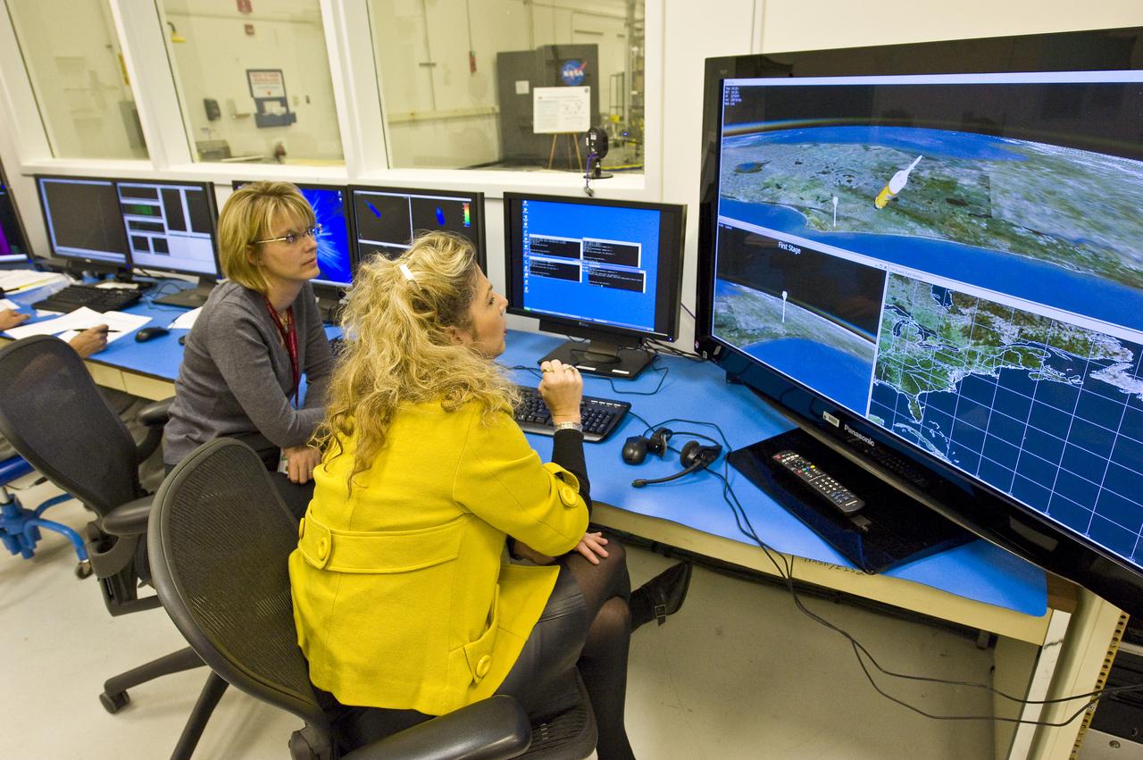
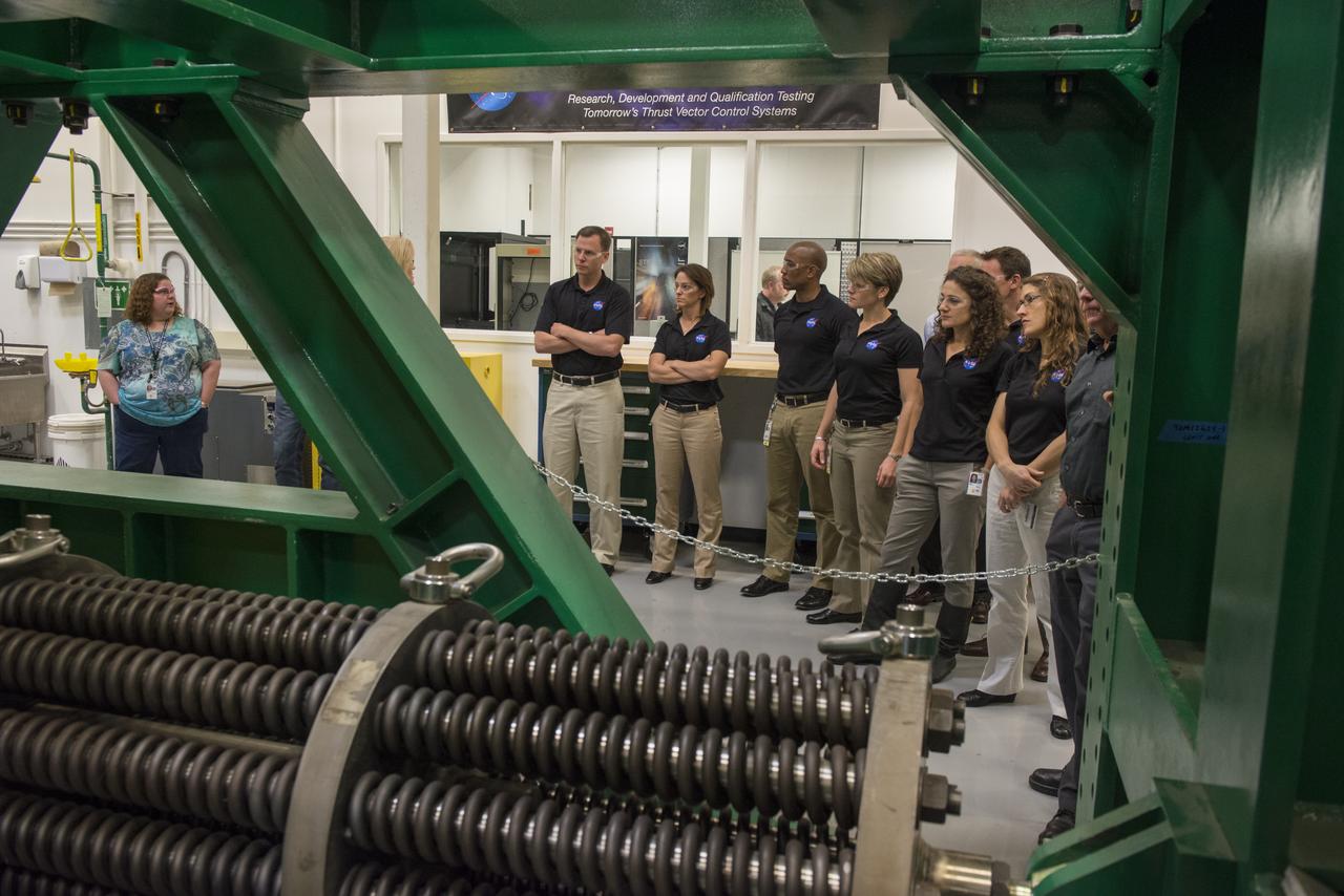
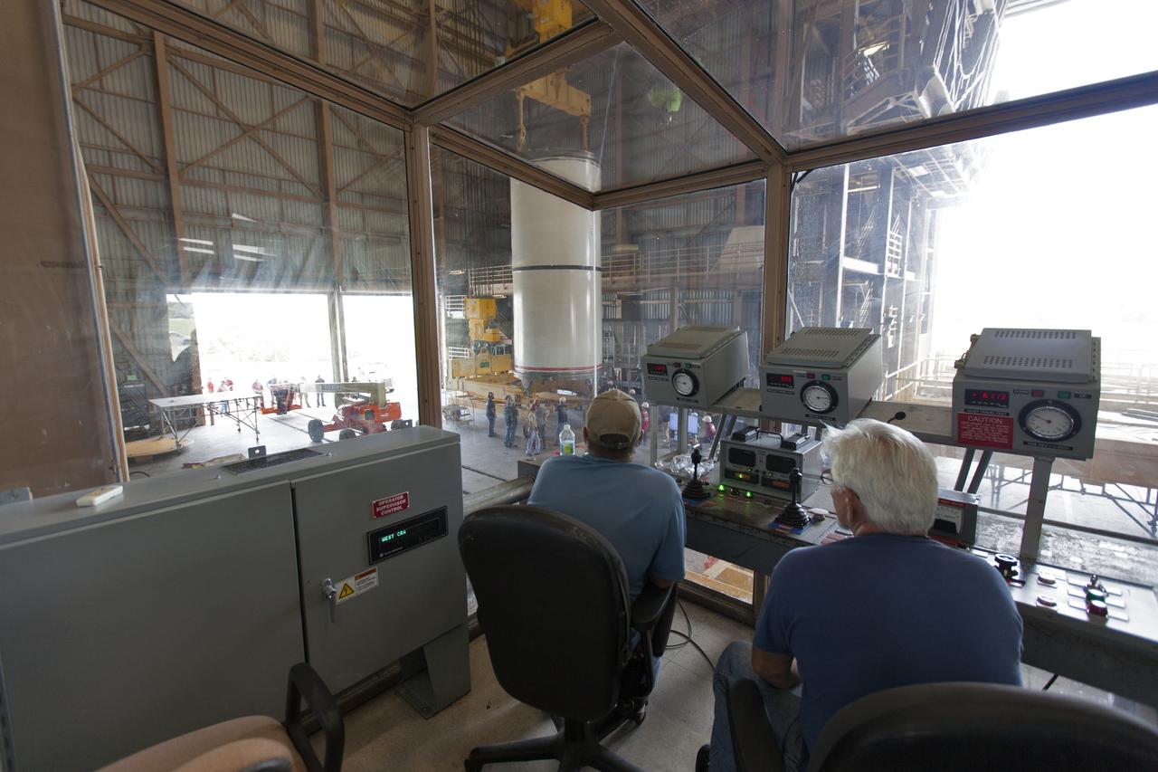
TVC TEST LAB/HARDWARE IN THE LOOP FACILITY FLIGHT SIMULATION CONTROL ROOM
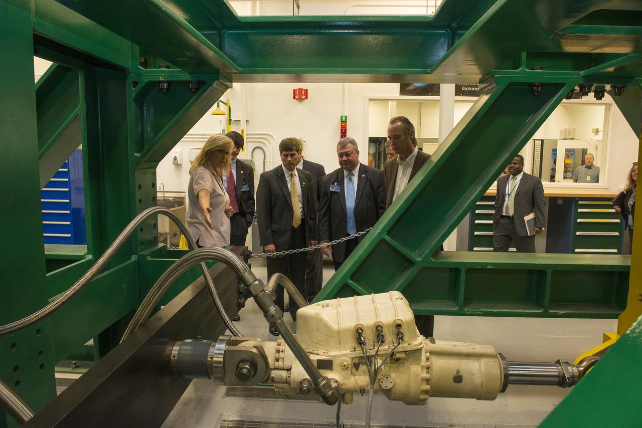
MIRANDA HOLTON GIVES OVERVIEW OF THRUST VECTOR CONTROL LAB
MIRANDA HOLTON GIVES OVERVIEW OF THRUST VECTOR CONTROL LAB
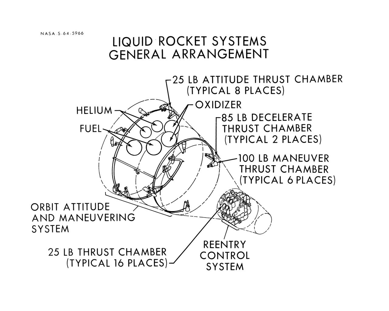
S64-05966 (1964) --- Diagram shows the general arrangement of the liquid rocket systems on the Gemini spacecraft are shown. The locations of the 25-pound, 85-pound and 100-pound thrusters of the orbital attitude and maneuver system and the 25-pound thrusters of the re-entry control system are shown.
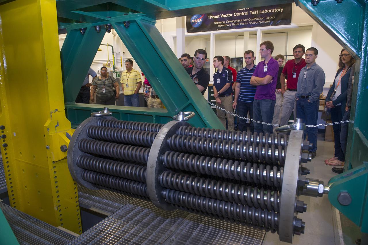
THE 2013 ASTRONAUT CANDIDATE CLASS VISITED THE THRUST VECTOR CONTROL TEST LAB AT MARSHALL'S PROPULSION RESEARCH DEVELOPMENT LABORATORY WHERE ENGINEERS ARE DEVELOPING AND TESTING THE SPACE LAUNCH SYSTEM'S GUIDANCE, NAVIGATION AND CONTROL SOFTWARE AND AVIONICS HARDWARE.
The modified F-18 High Alpha Research Vehicle (HARV) carries out air flow studies on a flight from the Dryden Flight Research Center, Edwards, California. Using oil, researchers were able to track the air flow across the wing at different speeds and angles of attack. A thrust vectoring system had been installed on the engines' exhaust nozzles for the high angle of attack research program. The thrust vectoring system, linked to the aircraft's flight control system, moves a set of three paddles on each engine to redirect thrust for directional control and increased maneuverability at angles of attack at up to 70 degrees.
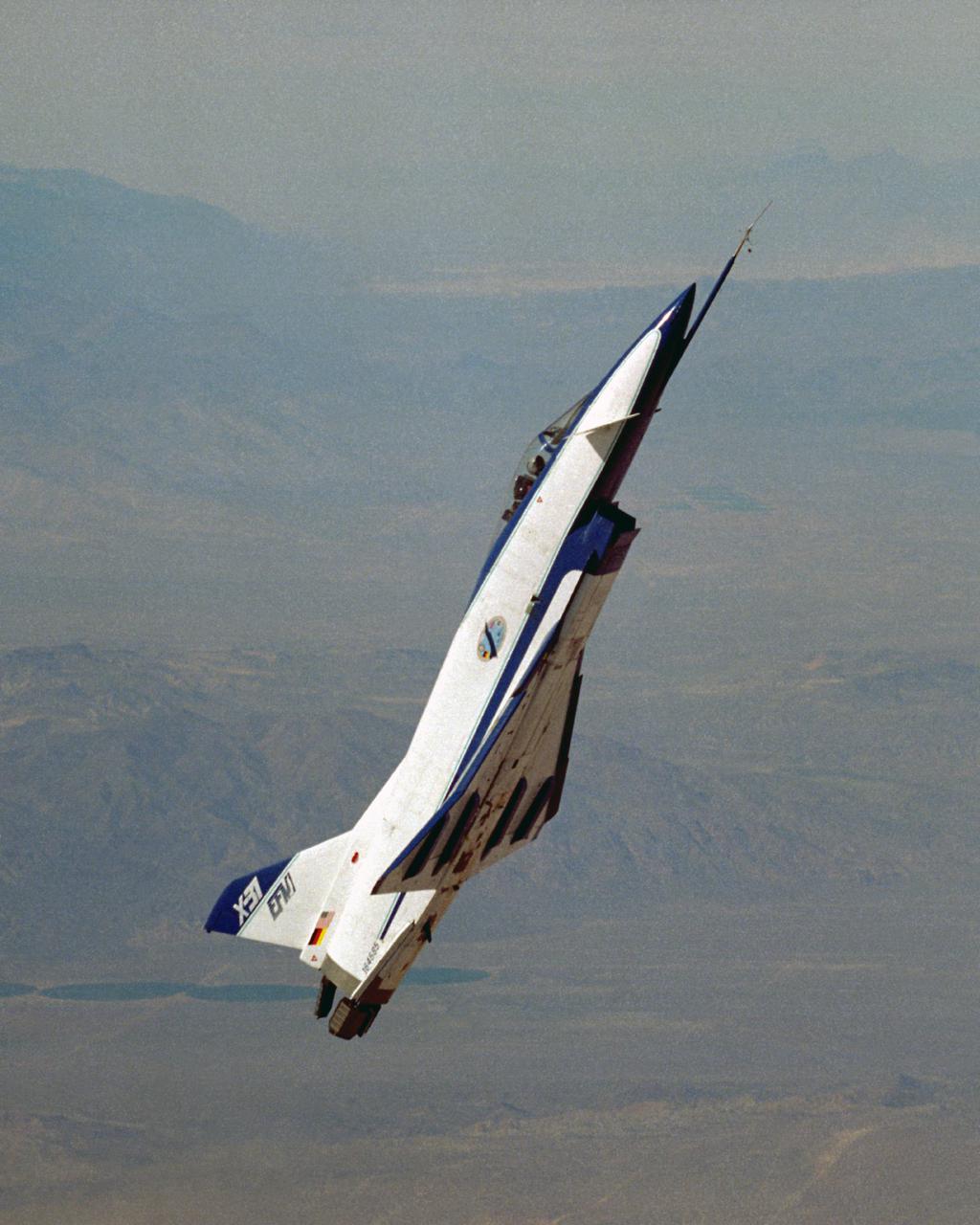
The X-31, the world’s first international X-plane, demonstrates controlled flight at high alpha courtesy of its canards and thrust vectoring paddles in the exhaust stream.
The F-15 Advanced Controls Technology for Integrated Vehicles, the first pre-production F-15B, shows its canards. Less obvious are the multi-axis thrust vectoring exhaust nozzles.
STS039-27-016 (28 April-6 May 1991) --- The Space Shuttle Discovery fires reaction control subsystem (RCS) thrusters in this 35mm frame, taken from inside the crew cabin. Seen in Discovery's payload bay are the tops of cannisters on the STP-1 payload, configured on the STS 39 Hitchhiker carrier; and the Air Force Program (AFP) 675 package. AFP-675 consists of the Cryogenic Infrared Radiance Instrumentation for Shuttle (CIRRIS)-1A; Far Ultraviolet Camera (FAR-UV) Experiment; Horizon Ultraviolet Program (HUP); Quadruple Ion Neutral Mass Spectrometer (QINMS); and the Uniformly Redundant Array (URA).
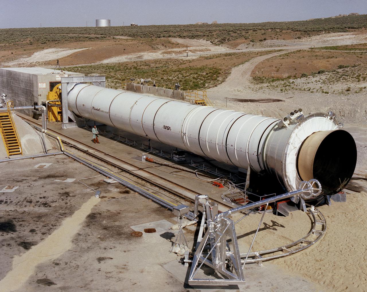
This photograph shows a static firing test of the Solid Rocket Qualification Motor-8 (QM-8) at the Morton Thiokol Test Site in Wasatch, Utah. The twin solid rocket boosters provide the majority of thrust for the first two minutes of flight, about 5.8 million pounds, augmenting the Shuttle's main propulsion system during liftoff. The major design drivers for the solid rocket motors (SRM's) were high thrust and reuse. The desired thrust was achieved by using state-of-the-art solid propellant and by using a long cylindrical motor with a specific core design that allows the propellant to burn in a carefully controlled marner. Under the direction of the Marshall Space Flight Center, the SRM's are provided by the Morton Thiokol Corporation.
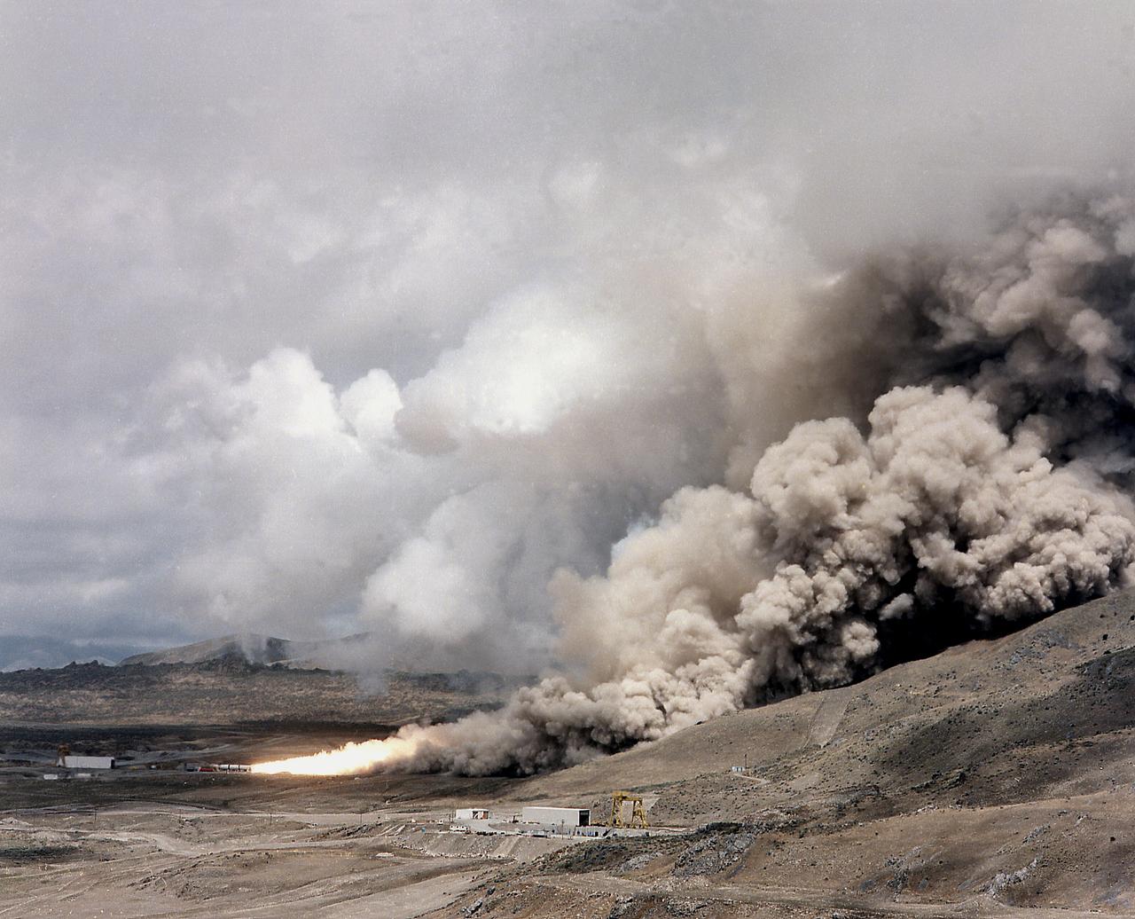
This photograph is a long shot view of a full scale solid rocket motor (SRM) for the solid rocket booster (SRB) being test fired at Morton Thiokol's Wasatch Operations in Utah. The twin boosters provide the majority of thrust for the first two minutes of flight, about 5.8 million pounds, augmenting the Shuttle's main propulsion system during liftoff. The major design drivers for the SRM's were high thrust and reuse. The desired thrust was achieved by using state-of-the-art solid propellant and by using a long cylindrical motor with a specific core design that allows the propellant to burn in a carefully controlled marner. Under the direction of the Marshall Space Flight Center, the SRM's are provided by the Morton Thiokol Corporation.

F-15B ACTIVE in flight
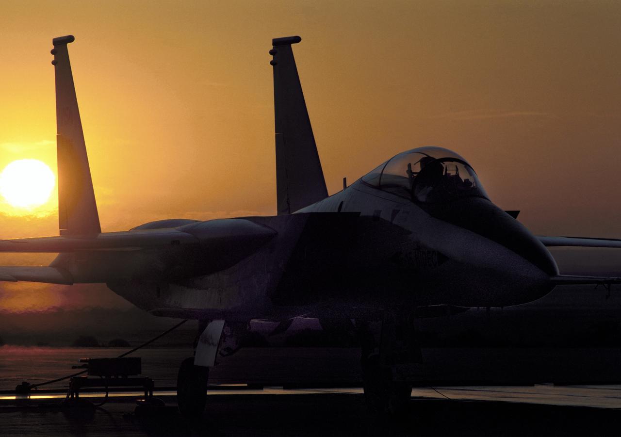
NASA's highly modified F-15A (Serial #71-0287) used for digital electronic flight and engine control systems research, at sunrise on the ramp at the Dryden Flight Research Facility, Edwards, California. The F-15 was called the HIDEC (Highly Integrated Digital Electronic Control) flight facility. Research programs flown on the testbed vehicle have demonstrated improved rates of climb, fuel savings, and engine thrust by optimizing systems performance. The aircraft also tested and evaluated a computerized self-repairing flight control system for the Air Force that detects damaged or failed flight control surfaces. The system then reconfigures undamaged control surfaces so the mission can continue or the aircraft is landed safely.
Engineers at the Marshall Space Flight Center (MSFC) have begun a series of engine tests on a new breed of space propulsion: a Reaction Control Engine developed for the Space Launch Initiative (SLI). The engine, developed by TRW Space and Electronics of Redondo Beach, California, is an auxiliary propulsion engine designed to maneuver vehicles in orbit. It is used for docking, reentry, attitude control, and fine-pointing while the vehicle is in orbit. The engine uses nontoxic chemicals as propellants, a feature that creates a safer environment for ground operators, lowers cost, and increases efficiency with less maintenance and quicker turnaround time between missions. Testing includes 30 hot-firings. This photograph shows the first engine test performed at MSFC that includes SLI technology. Another unique feature of the Reaction Control Engine is that it operates at dual thrust modes, combining two engine functions into one engine. The engine operates at both 25 and 1,000 pounds of force, reducing overall propulsion weight and allowing vehicles to easily maneuver in space. The low-level thrust of 25 pounds of force allows the vehicle to fine-point maneuver and dock while the high-level thrust of 1,000 pounds of force is used for reentry, orbit transfer, and coarse positioning. SLI is a NASA-wide research and development program, managed by the MSFC, designed to improve safety, reliability, and cost effectiveness of space travel for second generation reusable launch vehicles.
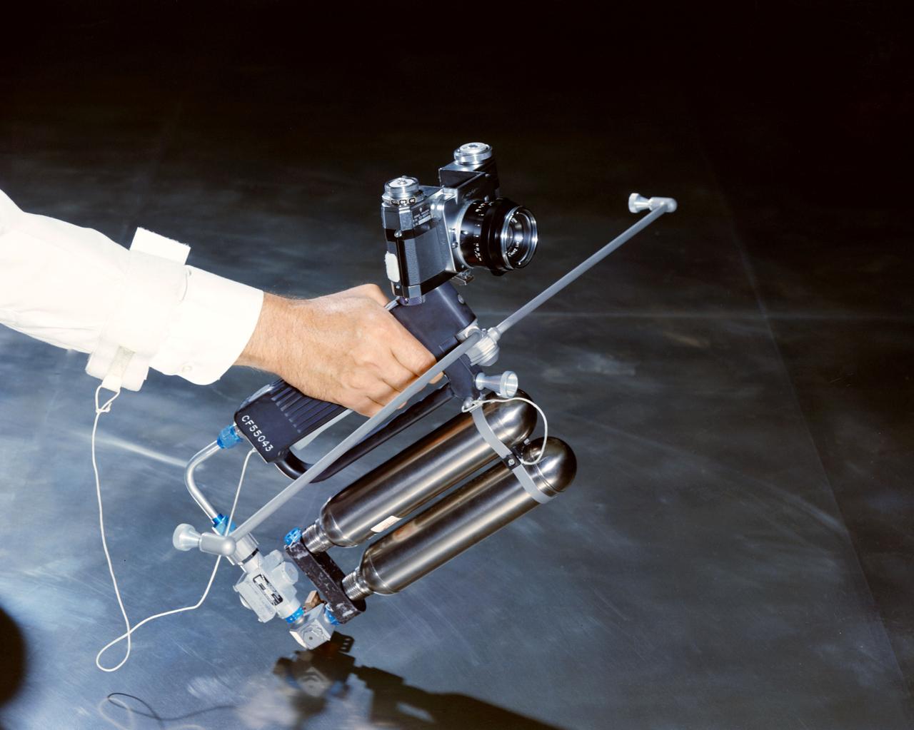
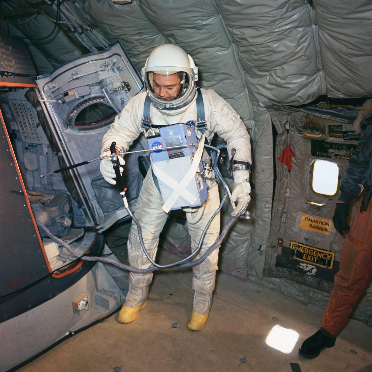
Hand-Held Self-Maneuvering Unit to be used during extravehicular activity (EVA) on Gemini 4 flight. It is an integral unit that contains its own high pressure metering valves and nozzles required to produce controlled thrust. A camera is mounted on the front of the unit.
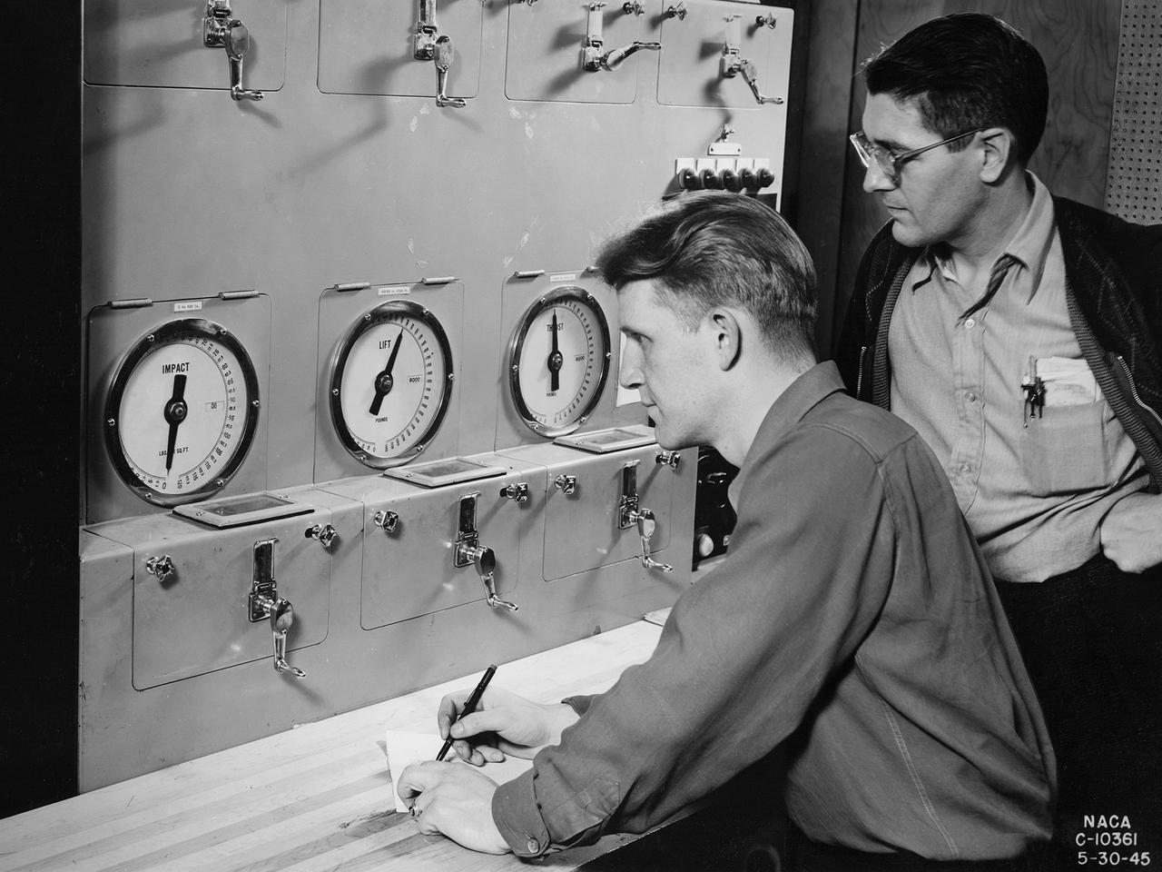
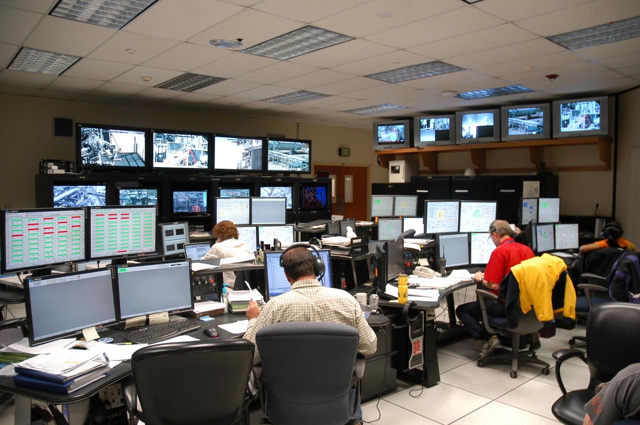
Researchers at the National Advisory Committee for Aeronautics (NACA) Aircraft Engine Research Laboratory monitor a ramjet's performance in the Altitude Wind Tunnel from the control room. The soundproof control room was just a few feet from the tunnel’s 20-foot-diameter test section. In the control room, the operators could control all aspects of the tunnel’s operation, including the air density, temperature, and speed. They also operated the engine or test article in the test section by controlling the angle-of-attack, speed, power, and other parameters. The men in this photograph are monitoring the engine’s thrust and lift. A NACA-designed 20-inch-diameter ramjet was installed in the tunnel in May 1945. Thrust figures from these runs were compared with drag data from tests of scale models in small supersonic tunnels to verify the ramjet’s feasibility. The tunnel was used to analyze the ramjet’s overall performance up to altitudes of 47,000 feet and speeds to Mach 1.84. The researchers found that an increase in altitude caused a reduction in the engine’s horsepower and identified optimal flameholder configurations.
KENNEDY SPACE CENTER, FLA. -- Inside NASA Kennedy Space Center’s Orbiter Processing Facility Bay 1, workers get ready to lift the sling placed round the forward reaction control system that will be installed on Atlantis. The forward reaction control system is located in the forward fuselage nose area. During ascent of the space shuttle, it provides the thrust for attitude (rotational) maneuvers (pitch, yaw and roll) and for small velocity changes along the orbiter axis (translation maneuvers).
KENNEDY SPACE CENTER, FLA. -- In NASA Kennedy Space Center’s Orbiter Processing Facility Bay 1, a technician inspects a point of installation of the forward reaction control system on Atlantis. The control system fits just behind the nose cone and provides the thrust for attitude (rotational) maneuvers (pitch, yaw and roll) and for small velocity changes along the orbiter axis (translation maneuvers). Processing of Atlantis is under way for mission STS-115, the 19th flight to the International Space Station.
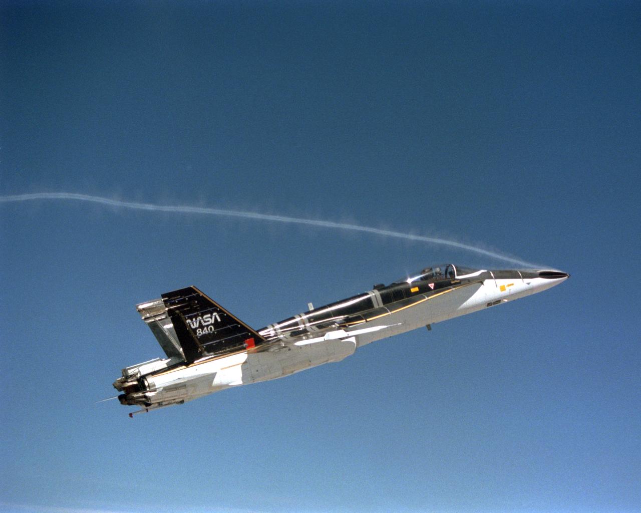
During the final phase of tests with the HARV, Dryden technicians installed nose strakes, which were panels that fitted flush against the sides of the forward nose. When the HARV was at a high alpha, the aerodynamics of the nose caused a loss of directional stability. Extending one or both of the strakes results in strong side forces that, in turn, generated yaw control. This approach, along with the aircraft's Thrust Vectoring Control system, proved to be stability under flight conditions in which conventional surfaces, such as the vertical tails, were ineffective.
KENNEDY SPACE CENTER, FLA. -- Inside NASA Kennedy Space Center’s Orbiter Processing Facility Bay 1, workers move the sling into place around the forward reaction control system that will be installed on Atlantis. When ready, the shuttle equipment will be lifted for installation. The forward reaction control system is located in the forward fuselage nose area. During ascent of the space shuttle, it provides the thrust for attitude (rotational) maneuvers (pitch, yaw and roll) and for small velocity changes along the orbiter axis (translation maneuvers).
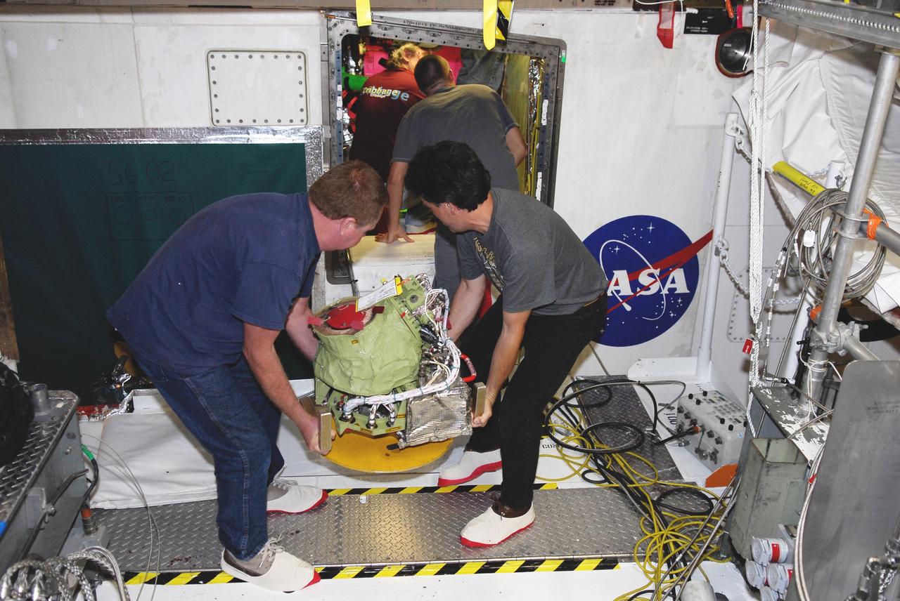
KENNEDY SPACE CENTER, FLA. -- In NASA Kennedy Space Center’s Orbiter Processing Facility Bay 1, technicians check details for the installation of the forward reaction control system on Atlantis (behind them). The control system fits just behind the nose cone and provides the thrust for attitude (rotational) maneuvers (pitch, yaw and roll) and for small velocity changes along the orbiter axis (translation maneuvers). Processing of Atlantis is under way for mission STS-115, the 19th flight to the International Space Station.
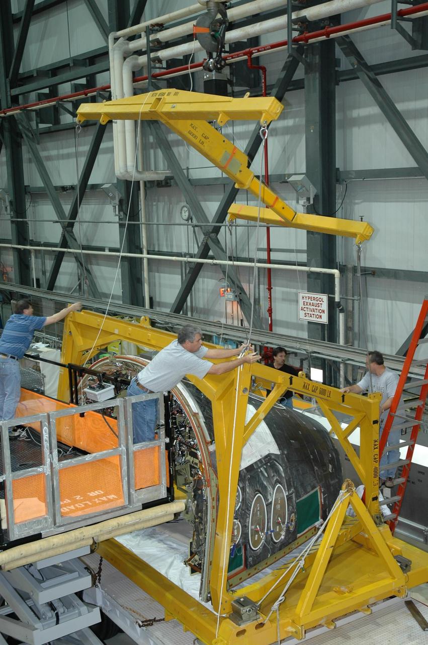
KENNEDY SPACE CENTER, FLA. -- Inside NASA Kennedy Space Center’s Orbiter Processing Facility Bay 1, workers secure the overhead crane to the sling placed round the forward reaction control system that will be installed on Atlantis. When ready, the shuttle equipment will be lifted for installation. The forward reaction control system is located in the forward fuselage nose area. During ascent of the space shuttle, it provides the thrust for attitude (rotational) maneuvers (pitch, yaw and roll) and for small velocity changes along the orbiter axis (translation maneuvers).
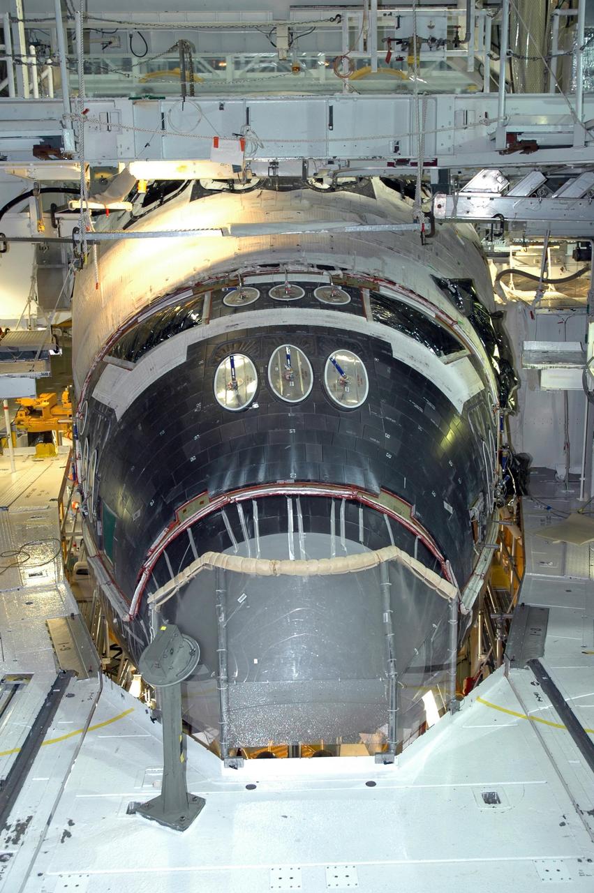
KENNEDY SPACE CENTER, FLA. -- In NASA Kennedy Space Center’s Orbiter Processing Facility Bay 1, installation of the forward reaction control system on Atlantis is complete. The control system fits just behind the nose cone and provides the thrust for attitude (rotational) maneuvers (pitch, yaw and roll) and for small velocity changes along the orbiter axis (translation maneuvers). Processing of Atlantis is under way for mission STS-115, the 19th flight to the International Space Station.
KENNEDY SPACE CENTER, FLA. -- Inside NASA Kennedy Space Center’s Orbiter Processing Facility Bay 1, workers make adjustments to the sling being placed round the forward reaction control system that will be installed on Atlantis. When ready, the shuttle equipment will be lifted for installation. The forward reaction control system is located in the forward fuselage nose area. During ascent of the space shuttle, it provides the thrust for attitude (rotational) maneuvers (pitch, yaw and roll) and for small velocity changes along the orbiter axis (translation maneuvers).
KENNEDY SPACE CENTER, FLA. -- In NASA Kennedy Space Center’s Orbiter Processing Facility Bay 1, workers are installing the forward reaction control system on Atlantis. The control system fits just behind the nose cone and provides the thrust for attitude (rotational) maneuvers (pitch, yaw and roll) and for small velocity changes along the orbiter axis (translation maneuvers). Processing of Atlantis is under way for mission STS-115, the 19th flight to the International Space Station.
KENNEDY SPACE CENTER, FLA. -- In NASA Kennedy Space Center’s Orbiter Processing Facility Bay 1, workers are installing the forward reaction control system on Atlantis. The control system fits just behind the nose cone and provides the thrust for attitude (rotational) maneuvers (pitch, yaw and roll) and for small velocity changes along the orbiter axis (translation maneuvers). Processing of Atlantis is under way for mission STS-115, the 19th flight to the International Space Station.
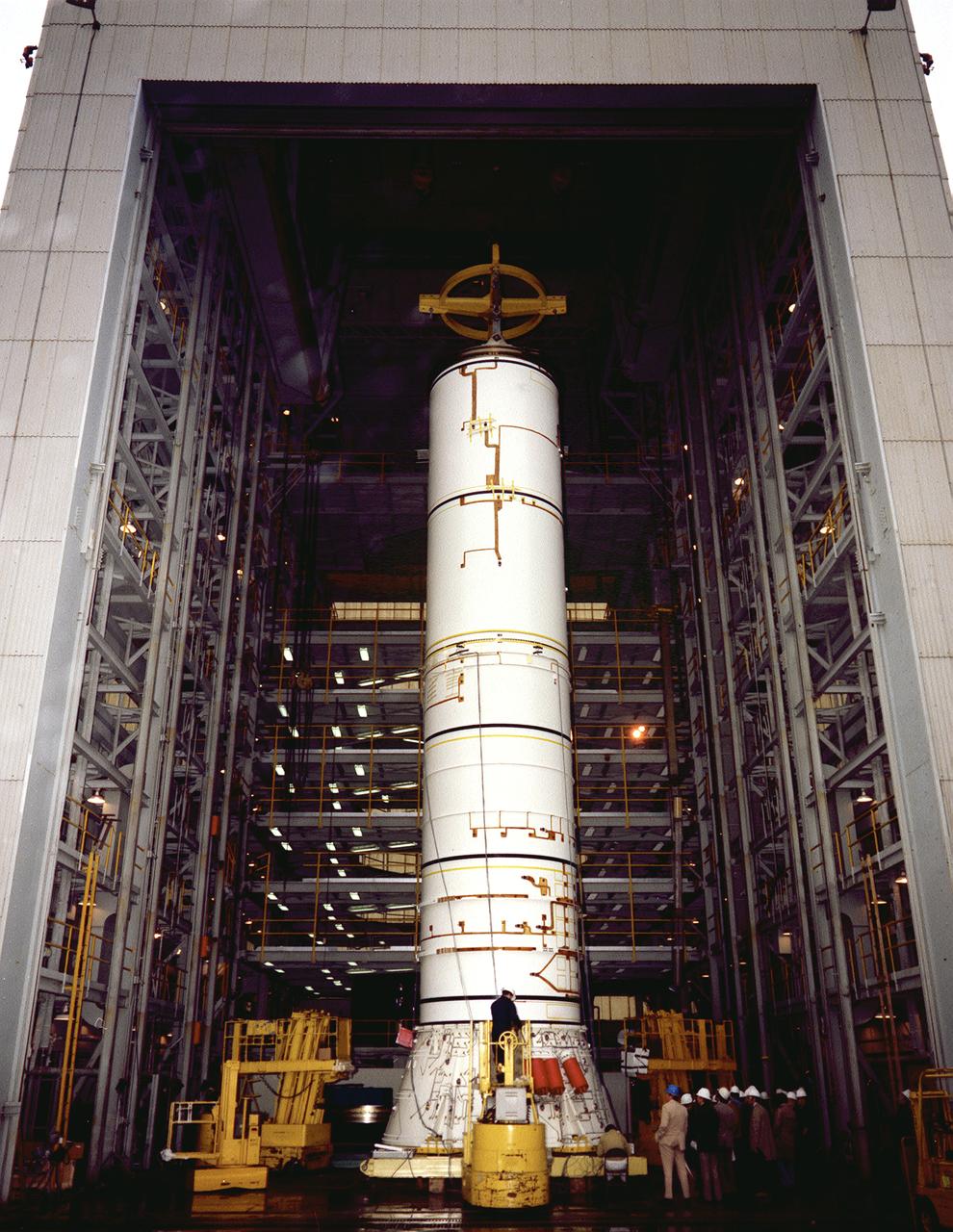
The structural test article to be used in the solid rocket booster (SRB) structural and load verification tests is being assembled in a high bay building of the Marshall Space Flight Center (MSFC). The Shuttle's two SRB's are the largest solids ever built and the first designed for refurbishment and reuse. Standing nearly 150-feet high, the twin boosters provide the majority of thrust for the first two minutes of flight, about 5.8 million pounds, augmenting the Shuttle's main propulsion system during liftoff. The major design drivers for the solid rocket motors (SRM's) were high thrust and reuse. The desired thrust was achieved by using state-of-the-art solid propellant and by using a long cylindrical motor with a specific core design that allows the propellant to burn in a carefully controlled marner. At burnout, the boosters separate from the external tank and drop by parachute to the ocean for recovery and subsequent refurbishment.
This is a photograph of the solid rocket booster's (SRB's) Qualification Motor-1 (QM-1) being prepared for a static firing in a test stand at the Morton Thiokol Test Site in Wasatch, Utah, showing the aft end of the booster. The twin boosters provide the majority of thrust for the first two minutes of flight, about 5.8 million pounds, augmenting the Shuttle's main propulsion system during liftoff. The major design drivers for the solid rocket motors (SRM's) were high thrust and reuse. The desired thrust was achieved by using state-of-the-art solid propellant and by using a long cylindrical motor with a specific core design that allows the propellant to burn in a carefully controlled marner. Under the direction of the Marshall Space Flight Center, the SRM's are provided by the Morton Thiokol Corporation.
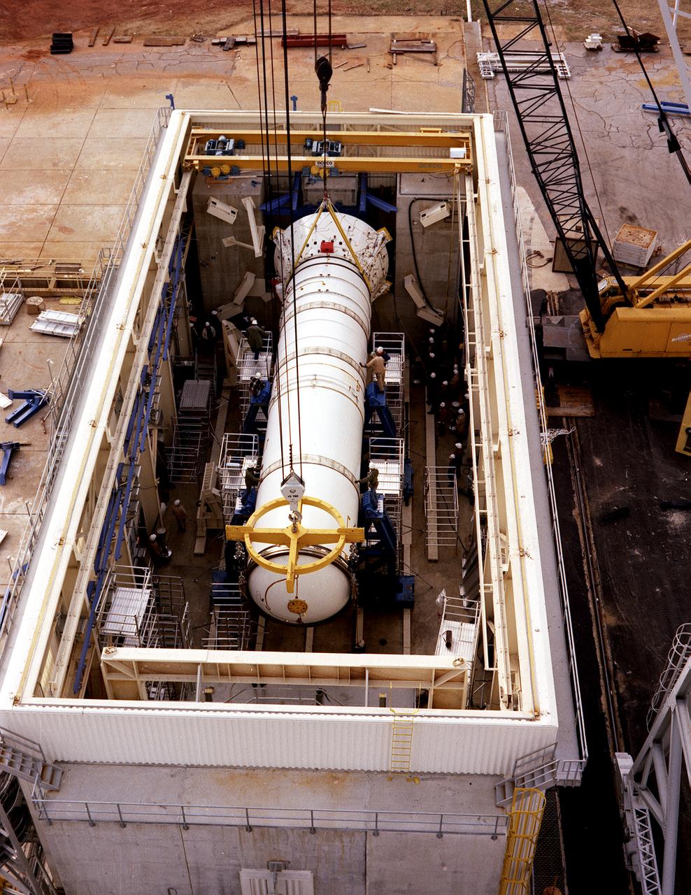
The solid rocket booster (SRB) structural test article is being installed in the Solid Rocket Booster Test Facility for the structural and load verification test at the Marshall Space Flight Center (MSFC). The Shuttle's two SRB's are the largest solids ever built and the first designed for refurbishment and reuse. Standing nearly 150-feet high, the twin boosters provide the majority of thrust for the first two minutes of flight, about 5.8 million pounds, augmenting the Shuttle's main propulsion system during liftoff. The major design drivers for the solid rocket motors (SRM's) were high thrust and reuse. The desired thrust was achieved by using state-of-the-art solid propellant and by using a long cylindrical motor with a specific core design that allows the propellant to burn in a carefully controlled marner. At burnout, the boosters separate from the external tank and drop by parachute to the ocean for recovery and subsequent refurbishment.
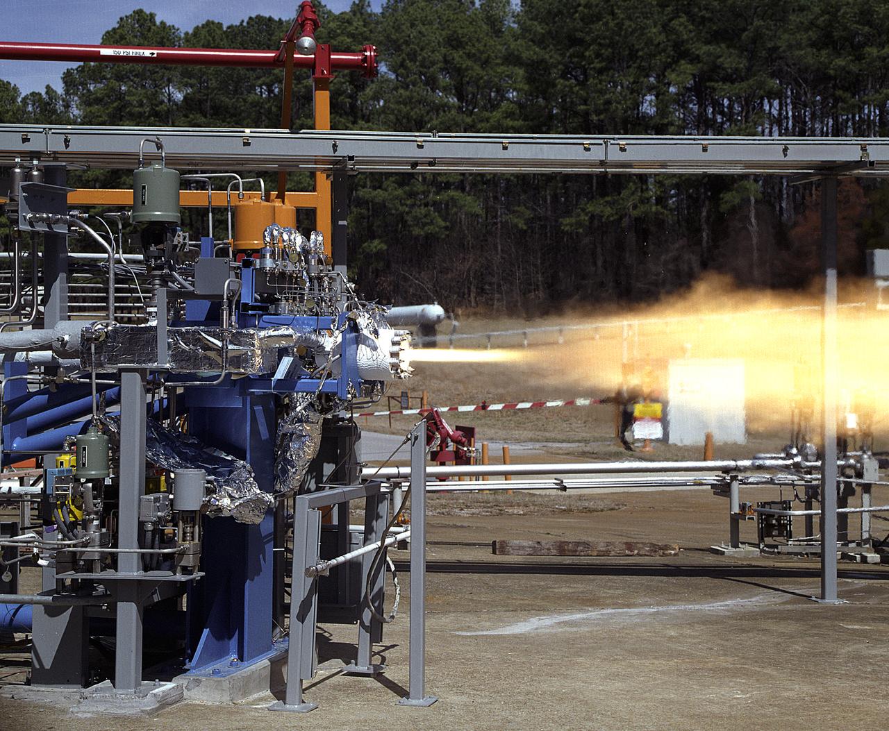
NASA's Marshall Space Flight Center (MSFC) in Huntsville, Alabama, has begun a series of engine tests on the Reaction Control Engine developed by TRW Space and Electronics for NASA's Space Launch Initiative (SLI). SLI is a technology development effort aimed at improving the safety, reliability, and cost effectiveness of space travel for reusable launch vehicles. The engine in this photo, the first engine tested at MSFC that includes SLI technology, was tested for two seconds at a chamber pressure of 185 pounds per square inch absolute (psia). Propellants used were liquid oxygen as an oxidizer and liquid hydrogen as fuel. Designed to maneuver vehicles in orbit, the engine is used as an auxiliary propulsion system for docking, reentry, fine-pointing, and orbit transfer while the vehicle is in orbit. The Reaction Control Engine has two unique features. It uses nontoxic chemicals as propellants, which creates a safer environment with less maintenance and quicker turnaround time between missions, and it operates in dual thrust modes, combining two engine functions into one engine. The engine operates at both 25 and 1,000 pounds of force, reducing overall propulsion weight and allowing vehicles to easily maneuver in space. The force of low level thrust allows the vehicle to fine-point maneuver and dock, while the force of the high level thrust is used for reentry, orbital transfer, and course positioning.
CAPE CANAVERAL, Fla. – Auxiliary power unit 3, or APU3, is ready for installation in space shuttle Endeavour for the STS-126 mission. The auxiliary power unit is a hydrazine-fueled, turbine-driven power unit that generates mechanical shaft power to drive a hydraulic pump that produces pressure for the orbiter's hydraulic system. There are three separate APUs, three hydraulic pumps and three hydraulic systems, located in the aft fuselage of the orbiter. When the three auxiliary power units are started five minutes before lift-off, the hydraulic systems are used to position the three main engines for activation, control various propellant valves on the engines and position orbiter aerosurfaces. The auxiliary power units are not operated after the first orbital maneuvering system thrusting period because hydraulic power is no longer required. One power unit is operated briefly one day before deorbit to support checkout of the orbiter flight control system. One auxiliary power unit is restarted before the deorbit thrusting period. The two remaining units are started after the deorbit thrusting maneuver and operate continuously through entry, landing and landing rollout. On STS-126, Endeavour will deliver a multi-purpose logistics module to the International Space Station. Launch is targeted for Nov. 10. Photo credit: NASA/Kim Shiflett
CAPE CANAVERAL, Fla. – In Orbiter Processing Facility bay No. 2, auxiliary power unit 3, or APU3, is in place on space shuttle Endeavour for the STS-126 mission. The auxiliary power unit is a hydrazine-fueled, turbine-driven power unit that generates mechanical shaft power to drive a hydraulic pump that produces pressure for the orbiter's hydraulic system. There are three separate APUs, three hydraulic pumps and three hydraulic systems, located in the aft fuselage of the orbiter. When the three auxiliary power units are started five minutes before lift-off, the hydraulic systems are used to position the three main engines for activation, control various propellant valves on the engines and position orbiter aerosurfaces. The auxiliary power units are not operated after the first orbital maneuvering system thrusting period because hydraulic power is no longer required. One power unit is operated briefly one day before deorbit to support checkout of the orbiter flight control system. One auxiliary power unit is restarted before the deorbit thrusting period. The two remaining units are started after the deorbit thrusting maneuver and operate continuously through entry, landing and landing rollout. On STS-126, Endeavour will deliver a multi-purpose logistics module to the International Space Station. Launch is targeted for Nov. 10. Photo credit: NASA/Kim Shiflett
CAPE CANAVERAL, Fla. – In Orbiter Processing Facility bay No. 2, technicians begin installation of an auxiliary power unit 3, or APU3, in space shuttle Endeavour for the STS-126 mission. The auxiliary power unit is a hydrazine-fueled, turbine-driven power unit that generates mechanical shaft power to drive a hydraulic pump that produces pressure for the orbiter's hydraulic system. There are three separate APUs, three hydraulic pumps and three hydraulic systems, located in the aft fuselage of the orbiter. When the three auxiliary power units are started five minutes before lift-off, the hydraulic systems are used to position the three main engines for activation, control various propellant valves on the engines and position orbiter aerosurfaces. The auxiliary power units are not operated after the first orbital maneuvering system thrusting period because hydraulic power is no longer required. One power unit is operated briefly one day before deorbit to support checkout of the orbiter flight control system. One auxiliary power unit is restarted before the deorbit thrusting period. The two remaining units are started after the deorbit thrusting maneuver and operate continuously through entry, landing and landing rollout. On STS-126, Endeavour will deliver a multi-purpose logistics module to the International Space Station. Launch is targeted for Nov. 10. Photo credit: NASA/Kim Shiflett
CAPE CANAVERAL, Fla. – In Orbiter Processing Facility bay No. 2, technicians install auxiliary power unit 3, or APU3, in space shuttle Endeavour for the STS-126 mission. The auxiliary power unit is a hydrazine-fueled, turbine-driven power unit that generates mechanical shaft power to drive a hydraulic pump that produces pressure for the orbiter's hydraulic system. There are three separate APUs, three hydraulic pumps and three hydraulic systems, located in the aft fuselage of the orbiter. When the three auxiliary power units are started five minutes before lift-off, the hydraulic systems are used to position the three main engines for activation, control various propellant valves on the engines and position orbiter aerosurfaces. The auxiliary power units are not operated after the first orbital maneuvering system thrusting period because hydraulic power is no longer required. One power unit is operated briefly one day before deorbit to support checkout of the orbiter flight control system. One auxiliary power unit is restarted before the deorbit thrusting period. The two remaining units are started after the deorbit thrusting maneuver and operate continuously through entry, landing and landing rollout. On STS-126, Endeavour will deliver a multi-purpose logistics module to the International Space Station. Launch is targeted for Nov. 10. Photo credit: NASA/Kim Shiflett
CAPE CANAVERAL, Fla. – In Orbiter Processing Facility bay No. 2, technicians begin installation of an auxiliary power unit 3, or APU3, in space shuttle Endeavour for the STS-126 mission. The auxiliary power unit is a hydrazine-fueled, turbine-driven power unit that generates mechanical shaft power to drive a hydraulic pump that produces pressure for the orbiter's hydraulic system. There are three separate APUs, three hydraulic pumps and three hydraulic systems, located in the aft fuselage of the orbiter. When the three auxiliary power units are started five minutes before lift-off, the hydraulic systems are used to position the three main engines for activation, control various propellant valves on the engines and position orbiter aerosurfaces. The auxiliary power units are not operated after the first orbital maneuvering system thrusting period because hydraulic power is no longer required. One power unit is operated briefly one day before deorbit to support checkout of the orbiter flight control system. One auxiliary power unit is restarted before the deorbit thrusting period. The two remaining units are started after the deorbit thrusting maneuver and operate continuously through entry, landing and landing rollout. On STS-126, Endeavour will deliver a multi-purpose logistics module to the International Space Station. Launch is targeted for Nov. 10. Photo credit: NASA/Kim Shiflett
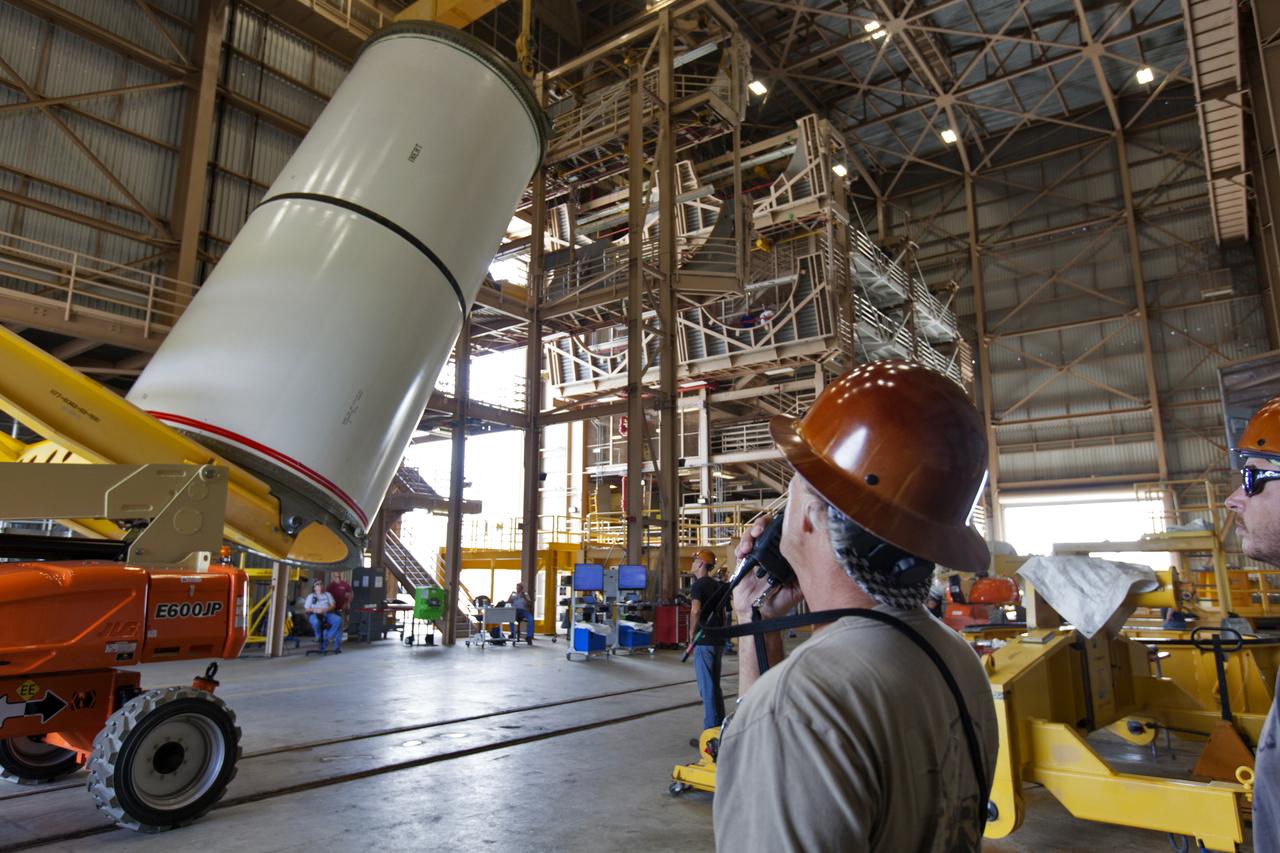
Jacobs technicians, on the Test and Operations Support Contract, practice crane operations with an inert booster rocket segment in the Rotation, Processing and Surge Facility on June 22, 2018, at NASA's Kennedy Space Center in Florida. Dual cranes are being used to move the segment from vertical to horizontal, a maneuver known as a "breakover rotation." As part of routine processing operations for the agency's Space Launch System (SLS) rocket, the RPSF team will receive all of the solid rocket fuel segments for inspection and preparation prior to transporting them to the Vehicle Assembly Building for stacking on the mobile launcher. Many pathfinding operations are being done to prepare for launch of the SLS and Orion spacecraft on Exploration Mission-1 and deep space missions.
Jacobs technicians, on the Test and Operations Support Contract, practice crane operations with an inert booster rocket segment in the Rotation, Processing and Surge Facility on June 22, 2018, at NASA's Kennedy Space Center in Florida. Dual cranes are being used to move the segment from vertical to horizontal, a maneuver known as a "breakover rotation." As part of routine processing operations for the agency's Space Launch System (SLS) rocket, the RPSF team will receive all of the solid rocket fuel segments for inspection and preparation prior to transporting them to the Vehicle Assembly Building for stacking on the mobile launcher. Many pathfinding operations are being done to prepare for launch of the SLS and Orion spacecraft on Exploration Mission-1 and deep space missions.
Jacobs technicians, on the Test and Operations Support Contract, check bolt fittings as they practice crane operations with an inert booster rocket segment in the Rotation, Processing and Surge Facility on June 22, 2018, at NASA's Kennedy Space Center in Florida. Dual cranes are being used to move the segment from vertical to horizontal, a maneuver known as a "breakover rotation." As part of routine processing operations for the agency's Space Launch System (SS) rocket, the RPSF team will receive all of the solid rocket fuel segments for inspection and preparation prior to transporting them to the Vehicle Assembly Building for stacking on the mobile launcher. Many pathfinding operations are being done to prepare for launch of the SLS and Orion spacecraft on Exploration Mission-1 and deep space missions.
STS064-08-032 (10 Sept. 1994) --- At the commander's station on the space shuttle Discovery's forward flight deck, astronaut Richard N. Richards, STS-64 mission commander, initiates a thruster firing of the spacecraft during operations with the Shuttle Plume Impingement Flight Experiment (SPIFEX). Photo credit: NASA or National Aeronautics and Space Administration
Jacobs technicians, on the Test and Operations Support Contract, practice crane operations with an inert booster rocket segment in the Rotation, Processing and Surge Facility on June 22, 2018, at NASA's Kennedy Space Center in Florida. Dual cranes were used to move the segment from vertical to horizontal, a maneuver known as a "breakover rotation." As part of routine processing operations for the agency's Space Launch System (SLS) rocket, the RPSF team will receive all of the solid rocket fuel segments for inspection and preparation prior to transporting them to the Vehicle Assembly Building for stacking on the mobile launcher. Many pathfinding operations are being done to prepare for launch of the SLS and Orion spacecraft on Exploration Mission-1 and deep space missions.
Jacobs technicians, on the Test and Operations Support Contract, practice crane operations with an inert booster rocket segment in the Rotation, Processing and Surge Facility on June 22, 2018, at NASA's Kennedy Space Center in Florida. Dual cranes are being used to move the segment from vertical to horizontal, a maneuver known as a "breakover rotation." As part of routine processing operations for the agency's Space Launch System (SLS) rocket, the RPSF team will receive all of the solid rocket fuel segments for inspection and preparation prior to transporting them to the Vehicle Assembly Building for stacking on the mobile launcher. Many pathfinding operations are being done to prepare for launch of the SLS and Orion spacecraft on Exploration Mission-1 and deep space missions.
A Jacobs technician, on the Test and Operations Support Contract, checks bolt fittings during practice crane operations with an inert booster rocket segment in the Rotation, Processing and Surge Facility on June 22, 2018, at NASA's Kennedy Space Center in Florida. Dual cranes will be used to move the segment from vertical to horizontal, a maneuver known as a "breakover rotation." As part of routine processing operations for the agency's Space Launch System (SLS) rocket, the RPSF team will receive all of the solid rocket fuel segments for inspection and preparation prior to transporting them to the Vehicle Assembly Building for stacking on the mobile launcher. Many pathfinding operations are being done to prepare for launch of the SLS and Orion spacecraft on Exploration Mission-1 and deep space missions.
Jacobs technicians, on the Test and Operations Support Contract, practice crane operations with an inert booster rocket segment in the Rotation, Processing and Surge Facility on June 22, 2018, at NASA's Kennedy Space Center in Florida. Dual cranes are being used to move the segment from vertical to horizontal, a maneuver known as a "breakover rotation." As part of routine processing operations for the agency's Space Launch System (SLS) rocket, the RPSF team will receive all of the solid rocket fuel segments for inspection and preparation prior to transporting them to the Vehicle Assembly Building for stacking on the mobile launcher. Many pathfinding operations are being done to prepare for launch of the SLS and Orion spacecraft on Exploration Mission-1 and deep space missions.
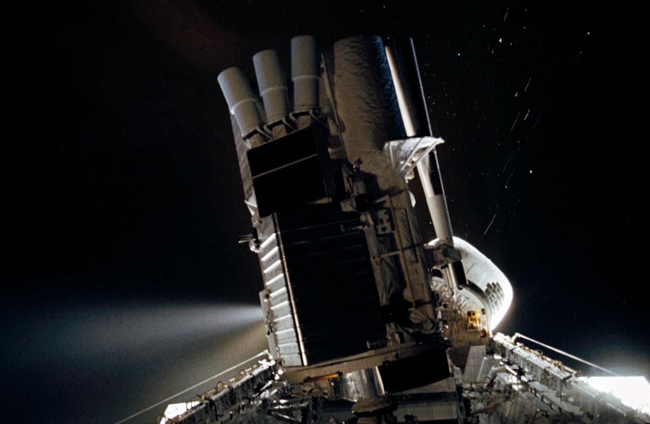
STS035-35-007 (2-10 Dec 1990) --- During the STS-35 mission, the Astronomy Laboratory 1 (ASTRO-1) payload, in its on-orbit operating configuration in the payload bay (PLB), is silhouetted against the firing of a reaction control system (RCS) jet. In the center of the frame, three ultraviolet telescopes are mounted and precisely co-aligned on a common structure, called the cruciform, that is attached to the instrument pointing system (IPS). Visible on the cruciform are Integrated Radiator System (IRS) (silver box on left), the Optical Sensor Package (OSP) (above IRS), the Ultraviolet Imaging Telescope (UIT), and the star tracker (S TRK) (far right). A right RCS jet is fired during this maneuver of Columbia, Orbiter Vehicle (OV) 102.
Jacobs technicians, on the Test and Operations Support Contract, practice crane operations with an inert booster rocket segment in the Rotation, Processing and Surge Facility on June 22, 2018, at NASA's Kennedy Space Center in Florida. Dual cranes are being used to move the segment from vertical to horizontal, a maneuver known as a "breakover rotation." As part of routine processing operations for the agency's Space Launch System (SLS) rocket, the RPSF team will receive all of the solid rocket fuel segments for inspection and preparation prior to transporting them to the Vehicle Assembly Building for stacking on the mobile launcher. Many pathfinding operations are being done to prepare for launch of the SLS and Orion spacecraft on Exploration Mission-1 and deep space missions.
Jacobs technicians, on the Test and Operations Support Contract, practice crane operations with an inert booster rocket segment in the Rotation, Processing and Surge Facility on June 22, 2018, at NASA's Kennedy Space Center in Florida. Dual cranes are being used to move the segment from vertical to horizontal, a maneuver known as a "breakover rotation." As part of routine processing operations for the agency's Space Launch System (SLS) rocket, the RPSF team will receive all of the solid rocket fuel segments for inspection and preparation prior to transporting them to the Vehicle Assembly Building for stacking on the mobile launcher. Many pathfinding operations are being done to prepare for launch of the SLS and Orion spacecraft on Exploration Mission-1 and deep space missions.
Jacobs technicians, on the Test and Operations Support Contract, practice crane operations with an inert booster rocket segment in the Rotation, Processing and Surge Facility on June 22, 2018, at NASA's Kennedy Space Center in Florida. Dual cranes are used to move the segment from vertical to horizontal, a maneuver known as a "breakover rotation." As part of routine processing operations for the agency's Space Launch System (SLS) rocket, the RPSF team will receive all of the solid rocket fuel segments for inspection and preparation prior to transporting them to the Vehicle Assembly Building for stacking on the mobile launcher. Many pathfinding operations are being done to prepare for launch of the SLS and Orion spacecraft on Exploration Mission-1 and deep space missions.
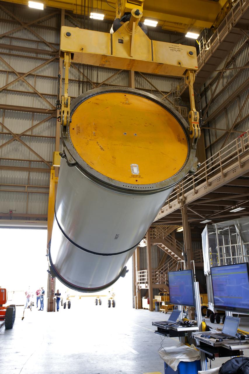
Jacobs technicians, on the Test and Operations Support Contract, practice crane operations with an inert booster rocket segment in the Rotation, Processing and Surge Facility on June 22, 2018, at NASA's Kennedy Space Center in Florida. Dual cranes are used to move the segment from vertical to horizontal, a maneuver known as a "breakover rotation." As part of routine processing operations for the agency's Space Launch System (SLS) rocket, the RPSF team will receive all of the solid rocket fuel segments for inspection and preparation prior to transporting them to the Vehicle Assembly Building for stacking on the mobile launcher. Many pathfinding operations are being done to prepare for launch of the SLS and Orion spacecraft on Exploration Mission-1 and deep space missions.
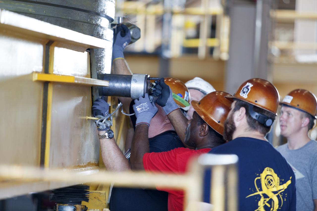
Jacobs technicians, on the Test and Operations Support Contract, check bolt fittings as they practice crane operations with an inert booster rocket segment in the Rotation, Processing and Surge Facility on June 22, 2018, at NASA's Kennedy Space Center in Florida. Dual cranes are being used to move the segment from vertical to horizontal, a maneuver known as a "breakover rotation." As part of routine processing operations for the agency's Space Launch System (SLS) rocket, the RPSF team will receive all of the solid rocket fuel segments for inspection and preparation prior to transporting them to the Vehicle Assembly Building for stacking on the mobile launcher. Many pathfinding operations are being done to prepare for launch of the SLS and Orion spacecraft on Exploration Mission-1 and deep space missions.
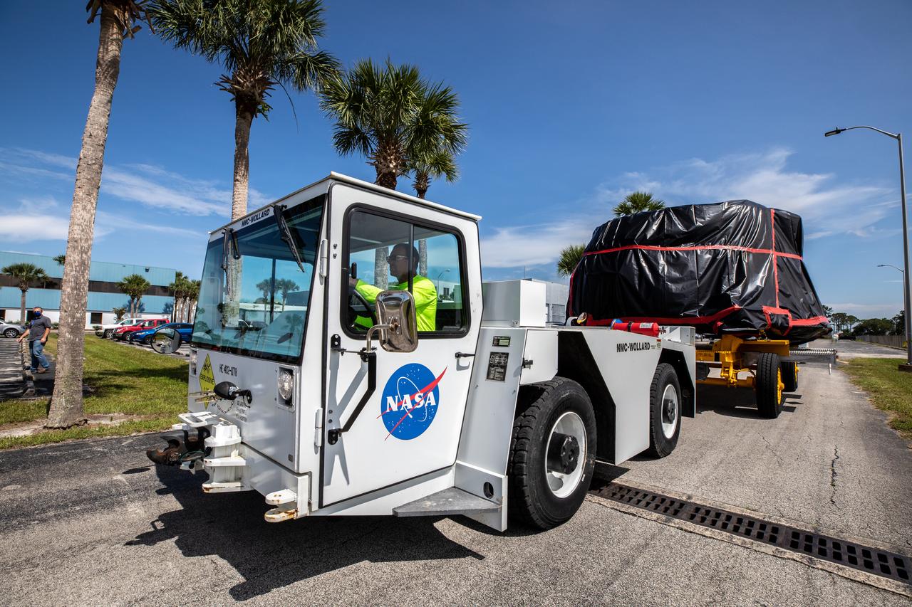
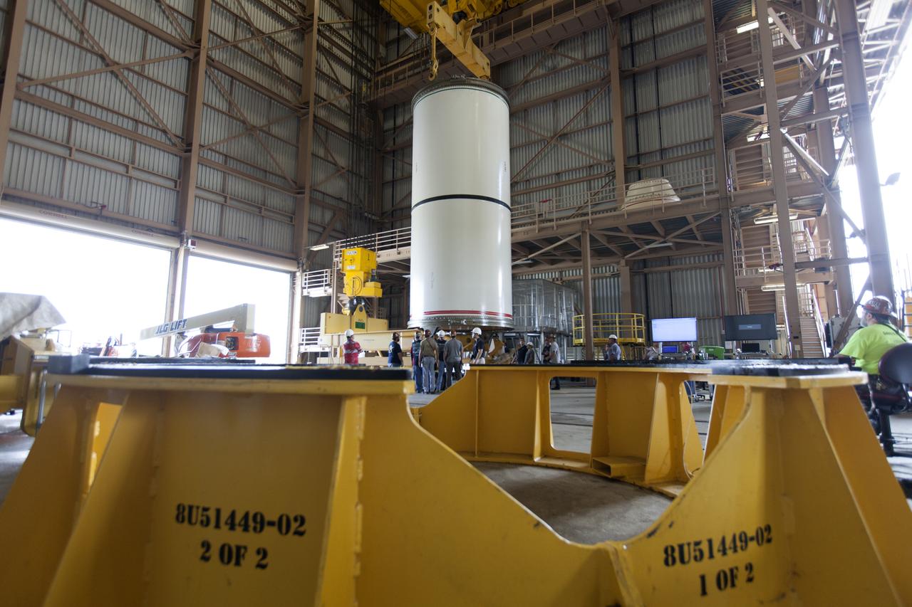
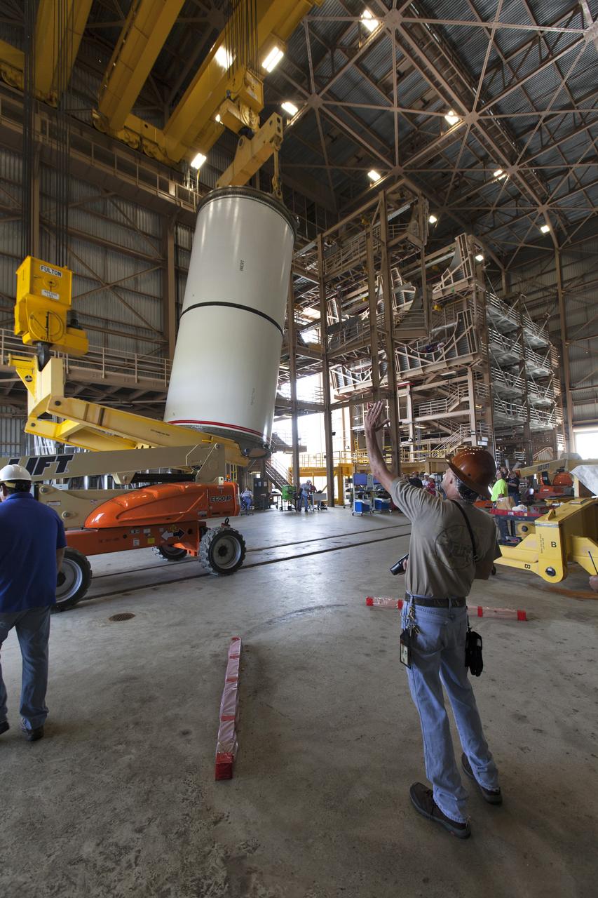
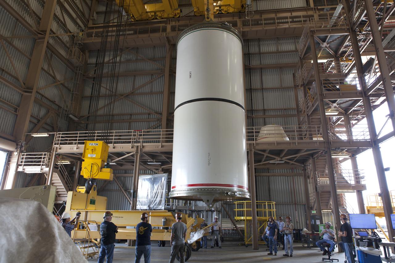
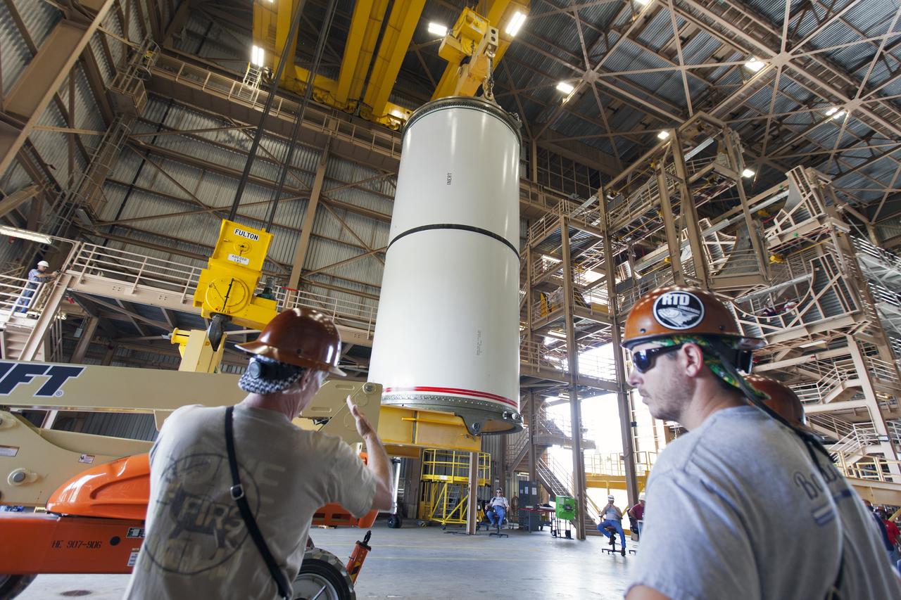
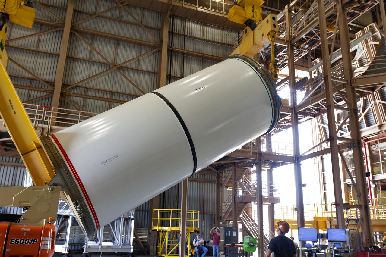
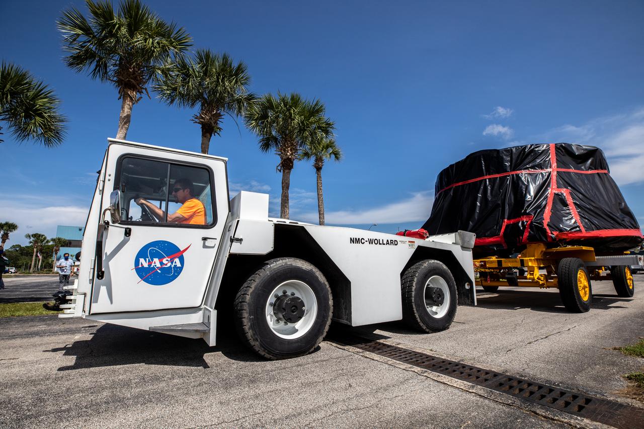
The Artemis I aft skirts for NASA's Space Launch System (SLS) rocket’s twin solid rocket boosters are transported to the Rotation Processing and Surge Facility (RPSF) at the agency’s Kennedy Space Center in Florida on June 10, 2020. The aft skirts were refurbished by Northrop Grumman. They house the thrust vector control system, which controls 70 percent of the steering during initial ascent of the SLS rocket. The segments will remain in the RPSF until ready for stacking with the forward and aft parts of the boosters on the mobile launcher in High Bay 3 of the Vehicle Assembly Building. Through the Artemis Program, NASA is working to land the first woman and next man on the Moon by 2024.
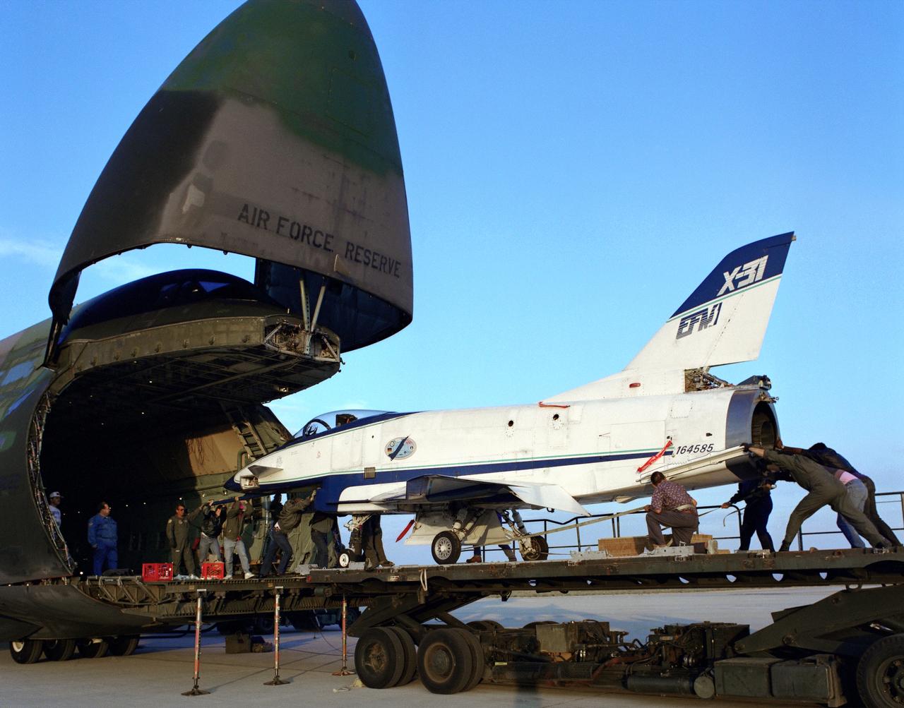
The X-31 Enhanced Fighter Maneuverability Technology Demonstrator Aircraft, based at the NASA Dryden Flight Research Center, Edwards, California, begins rolling aboard an Air Force Reserve C-5 transport which ferried it on May 22, 1995 to Europe where it was flown in the Paris Air Show in June 1995. To fit in the C-5 the right wing of the X-31 had to be removed. At the air show, the X-31 demonstrated the value of using thrust vectoring (directing engine exhaust flow) coupled with advanced flight control systems to provide controlled flight at very high angles of attack.

The Artemis I aft skirts for NASA's Space Launch System (SLS) rocket’s twin solid rocket boosters are transported to the Rotation Processing and Surge Facility (RPSF) at the agency’s Kennedy Space Center in Florida on June 10, 2020. The aft skirts were refurbished by Northrop Grumman. They house the thrust vector control system, which controls 70 percent of the steering during initial ascent of the SLS rocket. The segments will remain in the RPSF until ready for stacking with the forward and aft parts of the boosters on the mobile launcher in High Bay 3 of the Vehicle Assembly Building. Through the Artemis Program, NASA is working to land the first woman and next man on the Moon by 2024.
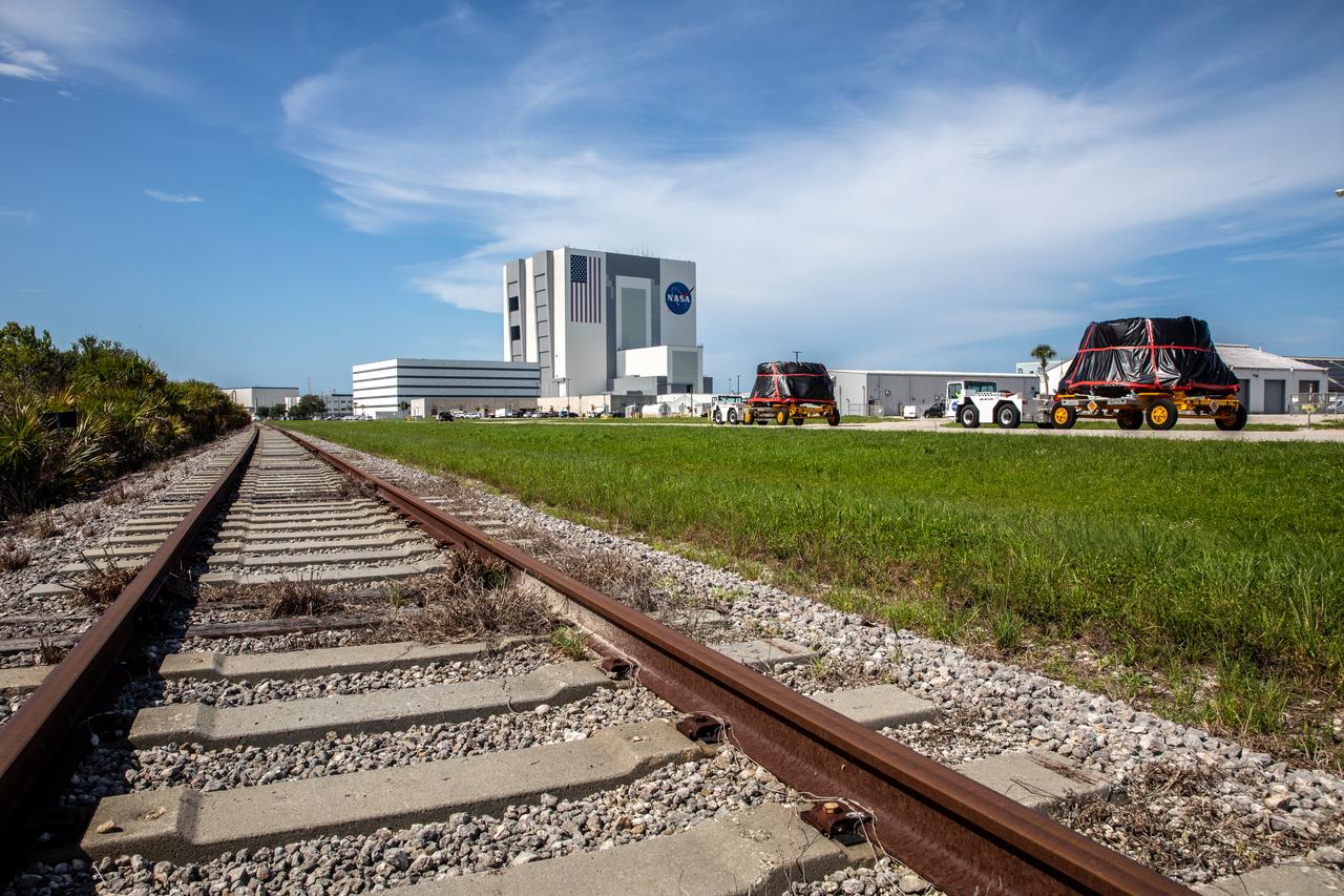
The Artemis I aft skirts for NASA’s Space Launch System (SLS) rocket’s twin solid rocket boosters are moved along the road to the Rotation, Processing and Surge Facility (RPSF) at the agency’s Kennedy Space Center in Florida on June 10, 2020. The aft skirts were refurbished by Northrop Grumman. They house the thrust vector control system, which controls 70 percent of the steering during initial ascent of the SLS rocket. The aft skirts will remain in the RPSF until ready for stacking with the forward and aft parts of the boosters on the mobile launcher in High Bay 3 of the Vehicle Assembly Building. Through the Artemis Program, NASA is working to land the first woman and next man on the Moon by 2024.
The Artemis I aft skirts for NASA's Space Launch System (SLS) rocket’s twin solid rocket boosters are transported to the Rotation Processing and Surge Facility (RPSF) at the agency’s Kennedy Space Center in Florida on June 10, 2020. The aft skirts were refurbished by Northrop Grumman. They house the thrust vector control system, which controls 70 percent of the steering during initial ascent of the SLS rocket. The segments will remain in the RPSF until ready for stacking with the forward and aft parts of the boosters on the mobile launcher in High Bay 3 of the Vehicle Assembly Building. Through the Artemis Program, NASA is working to land the first woman and next man on the Moon by 2024.
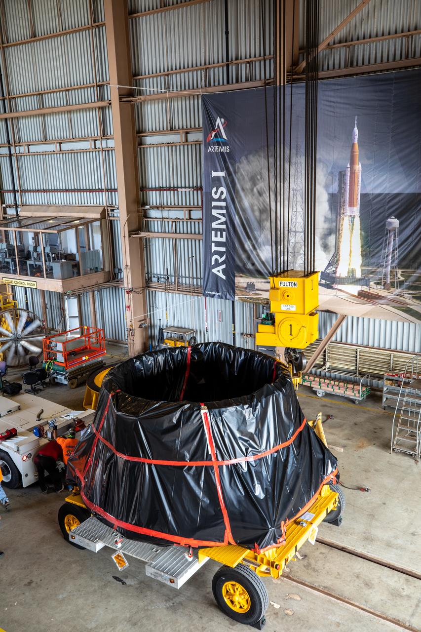
The first of two Artemis I aft skirts for NASA's Space Launch System (SLS) rocket’s twin solid rocket boosters is moved into the Rotation Processing and Surge Facility (RPSF) at the agency’s Kennedy Space Center in Florida on June 10, 2020. The aft skirts were refurbished by Northrop Grumman. They house the thrust vector control system, which controls 70 percent of the steering during initial ascent of the SLS rocket. The segments will remain in the RPSF until ready for stacking with the forward and aft parts of the boosters on the mobile launcher in High Bay 3 of the Vehicle Assembly Building. Through the Artemis Program, NASA is working to land the first woman and next man on the Moon by 2024.
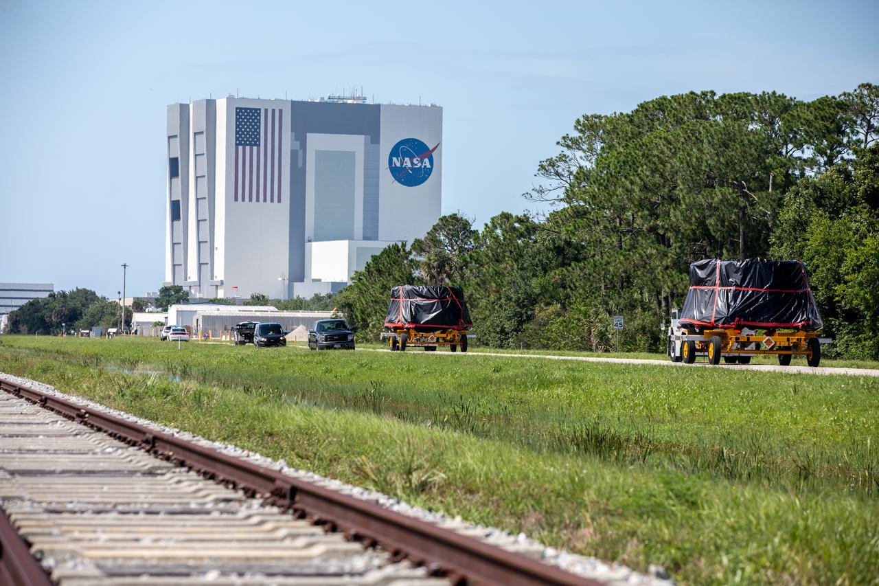
The Artemis I aft skirts for NASA’s Space Launch System (SLS) rocket’s twin solid rocket boosters are moved along the road to the Rotation, Processing and Surge Facility (RPSF) at the agency’s Kennedy Space Center in Florida on June 10, 2020. The aft skirts were refurbished by Northrop Grumman. They house the thrust vector control system, which controls 70 percent of the steering during initial ascent of the SLS rocket. The aft skirts will remain in the RPSF until ready for stacking with the forward and aft parts of the boosters on the mobile launcher in High Bay 3 of the Vehicle Assembly Building. Through the Artemis Program, NASA is working to land the first woman and next man on the Moon by 2024.
CAPE CANAVERAL, Fla. – The forward reaction control system, or FRCS, will be removed from space shuttle Endeavour's forward fuselage nose area in NASA Kennedy Space Center's Orbiter Processing Facility 2. The FRCS provides the thrust for attitude (rotational) maneuvers (pitch, yaw and roll) and for small velocity changes along the orbiter axis (translation maneuvers). Endeavour is designated as the shuttle for the STS-130 mission, targeted for launch in February 2010. Photo credit: NASA/Jack Pfaller
CAPE CANAVERAL, Fla. – In NASA Kennedy Space Center's Orbiter Processing Facility 2, a worker removes the forward reaction control system, or FRCS, from space shuttle Endeavour's forward fuselage nose area. The FRCS provides the thrust for attitude (rotational) maneuvers (pitch, yaw and roll) and for small velocity changes along the orbiter axis (translation maneuvers). Endeavour is designated as the shuttle for the STS-130 mission, targeted for launch in February 2010. Photo credit: NASA/Jack Pfaller
Assembling activities of the Skylab cluster are shown in this photograph. The Orbital Workshop (OWS) was lowered for joining to aft skirt and placed over the thrust structure inside the assembly tower. The OWS provided living and working quarters for the Skylab crew and the thruster provided short-term attitude control of the Skylab. The Marshall Space Flight Center had responsibilities for the design and development of the Skylab hardware, and management of experiments.
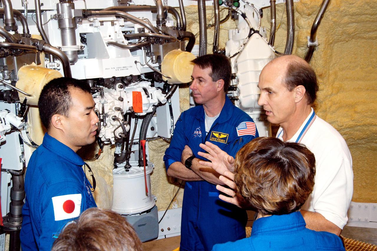
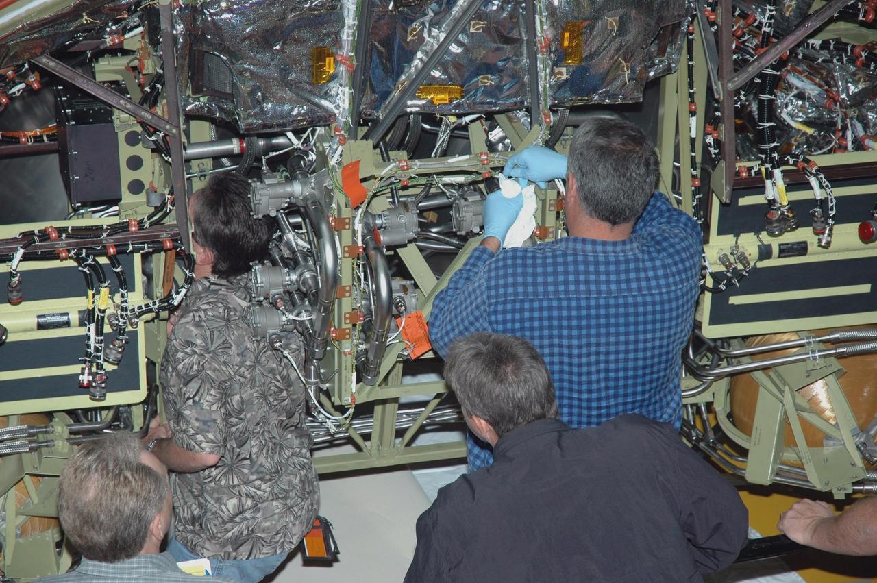
KENNEDY SPACE CENTER, FLA. - In the SRB Assembly and Refurbishment Facility, STS-114 Mission Specialists Soichi Noguchi (left), Stephen Robinson (center) and Commander Eileen Collins (back to camera) are briefed by Bob Dougert, manager of Test Engineering and Operations, on the thrust vector control system in solid rocket boosters. The crew is at KSC for familiarization with Shuttle and mission equipment. The STS-114 mission is Logistics Flight 1, which is scheduled to deliver supplies and equipment, plus the external stowage platform, to the International Space Station.
KENNEDY SPACE CENTER, FLA. - In the Orbiter Processing Facility, the left-hand Orbital Maneuvering System (OMS) pod is maneuvered toward the engine interfaces on the orbiter Discovery for installation. The Orbital Maneuvering System provides the thrust for orbit insertion, orbit circularization, orbit transfer, rendezvous, deorbit, abort to orbit and abort once around. It can provide up to 1,000 pounds of propellant to the aft reaction control system. Each pod contains one OMS engine and the hardware needed to pressurize, store and distribute the propellants to perform the velocity maneuvers.

CAPE CANAVERAL, Fla. – The forward reaction control system, or FRCS, will be removed from space shuttle Endeavour's forward fuselage nose area in NASA Kennedy Space Center's Orbiter Processing Facility 2. The FRCS provides the thrust for attitude (rotational) maneuvers (pitch, yaw and roll) and for small velocity changes along the orbiter axis (translation maneuvers). Endeavour is designated as the shuttle for the STS-130 mission, targeted for launch in February 2010. Photo credit: NASA/Jack Pfaller

KENNEDY SPACE CENTER, FLA. - Workers in the Orbiter Processing Facility watch closely as Discovery’s Forward Reaction Control System (FRCS) is lowered into position in the orbiter’s forward fuselage nose area. The FRCS provides the thrust for attitude (rotational) maneuvers (pitch, yaw and roll) and for small velocity changes along the orbiter axis (translation maneuvers). Discovery is designated as the Return to Flight vehicle for mission STS-114, no earlier than March 2005.
S66-19184 (1966) --- Close-up view of the Hand Held Maneuvering Unit which will be used by astronaut David R. Scott during the extravehicular activity on the Gemini-8 spaceflight. High pressure cold gas released through the unit's nozzles produces the required controlled thrust to maneuver in a zero-gravity environment. Photo credit: NASA
S66-28782 (1 April 1966) --- Astronaut Michael Collins, prime crew pilot of the Gemini-10 spaceflight, experiences a condition of weightlessness during zero-gravity egress training. A KC-135 Air Force plane, flying a parabolic curve, creates a weightless environment as a training exercise in preparation for spaceflight. The Hand-Held Maneuvering Unit in his right hand produces controlled thrust for moving about. Photo credit: NASA
S66-28636 (1 April 1966) --- Astronaut Clifton C. Williams Jr., backup crew pilot of the Gemini-10 spaceflight, undergoes zero-gravity egress training. A KC-135 Air Force plane, flying a parabolic curve, creates a weightless environment as a training exercise in preparation for spaceflight. The Hand-Held Maneuvering Unit in his right hand produces controlled thrust for moving about. Photo credit: NASA
CAPE CANAVERAL, Fla. – In NASA Kennedy Space Center's Orbiter Processing Facility 2, workers begin removing the forward reaction control system, or FRCS, from space shuttle Endeavour's forward fuselage nose area. The FRCS provides the thrust for attitude (rotational) maneuvers (pitch, yaw and roll) and for small velocity changes along the orbiter axis (translation maneuvers). Endeavour is designated as the shuttle for the STS-130 mission, targeted for launch in February 2010. Photo credit: NASA/Jack Pfaller
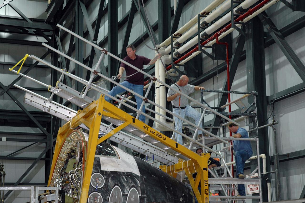
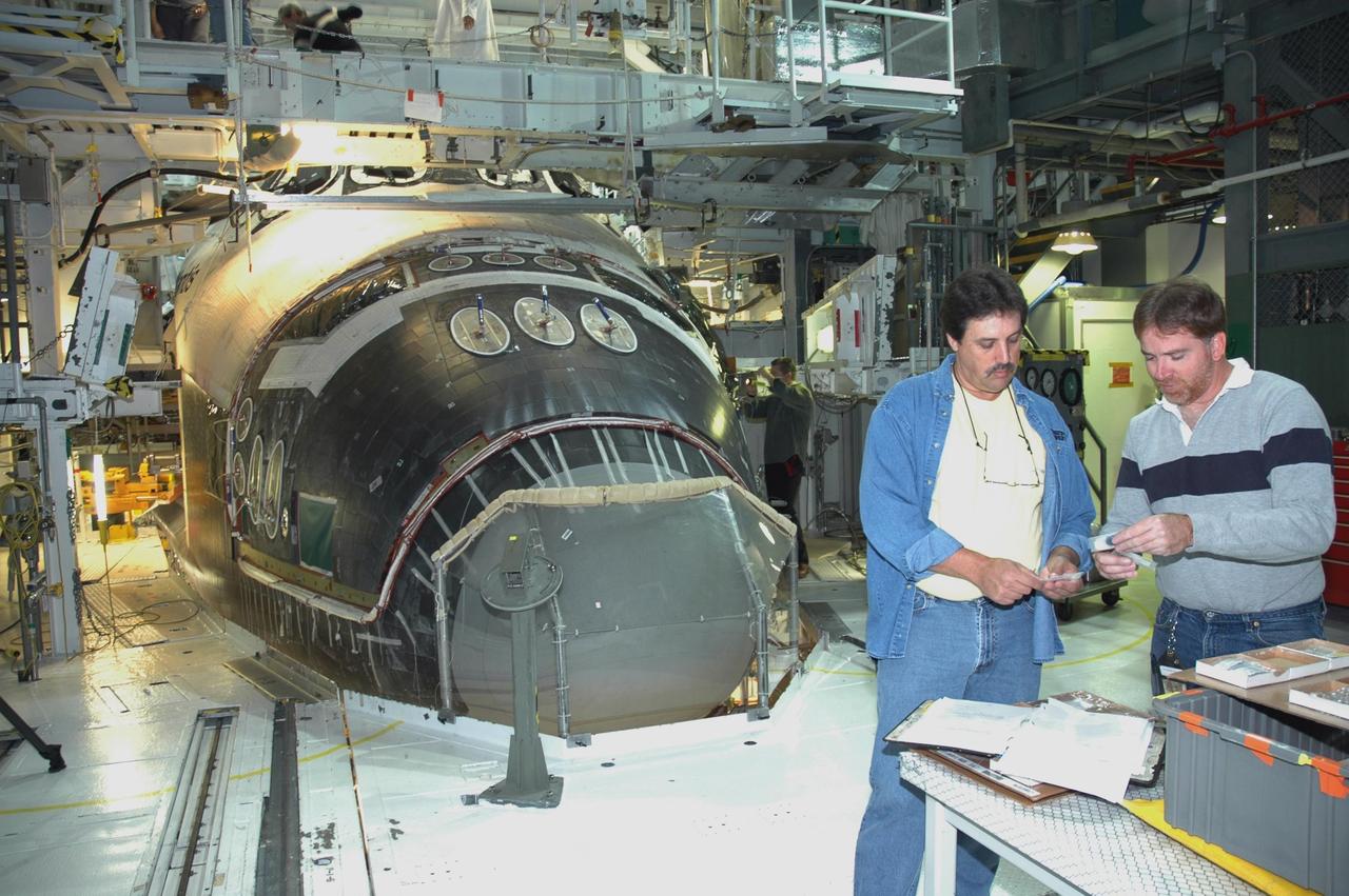
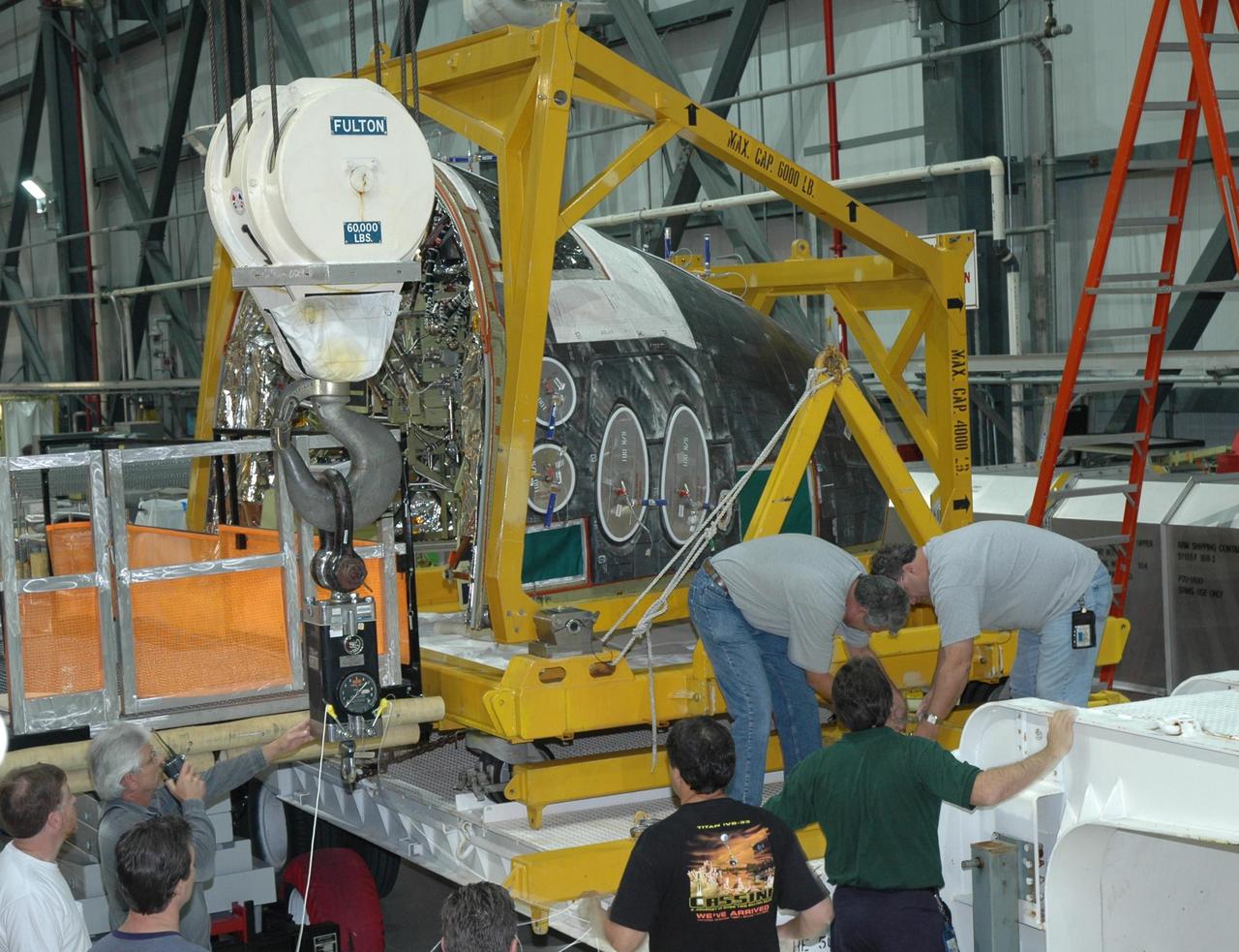
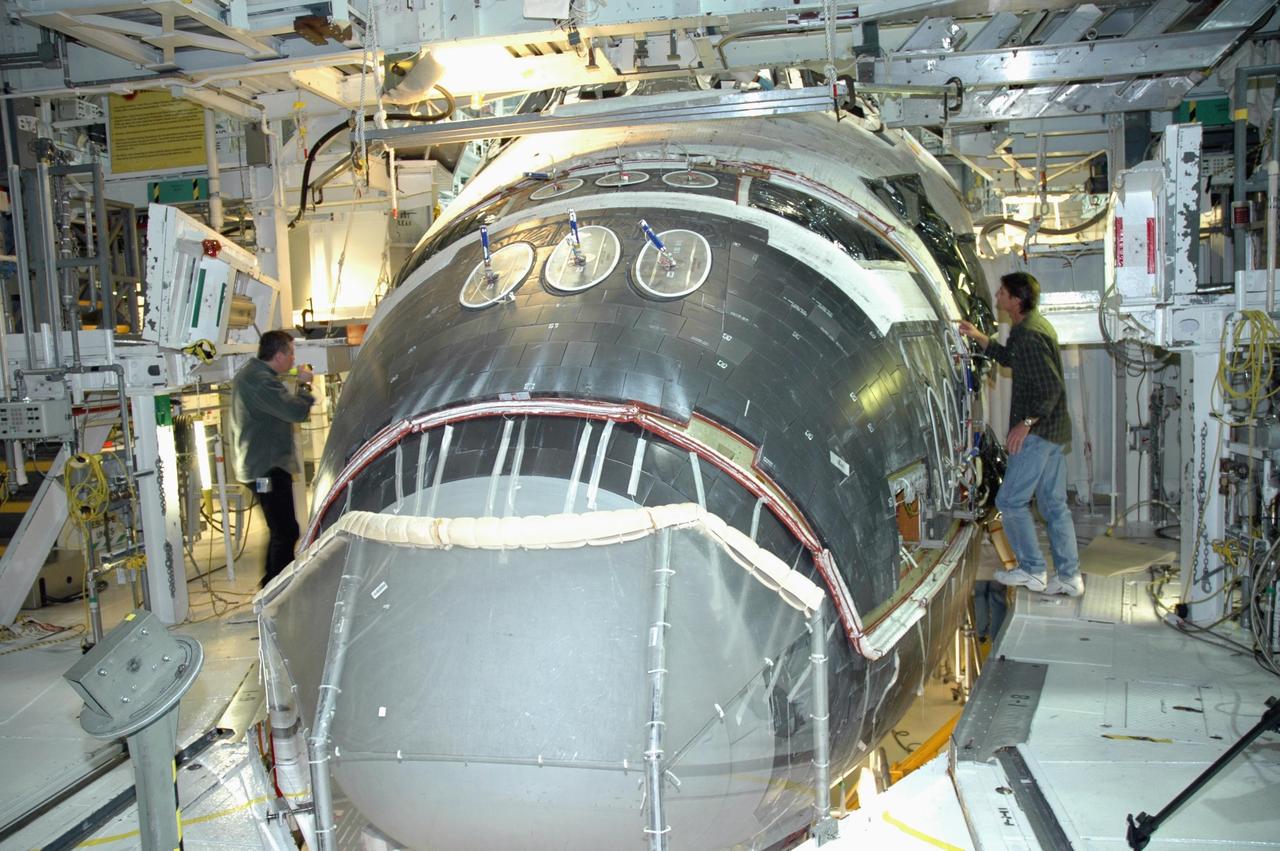
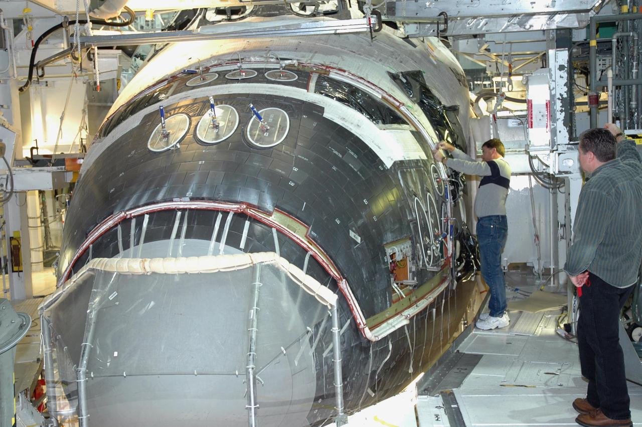
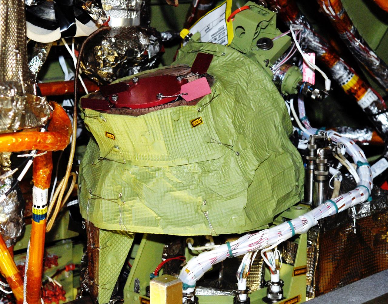
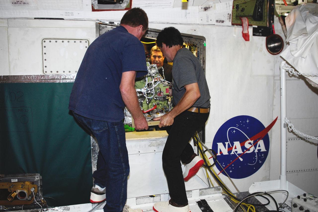
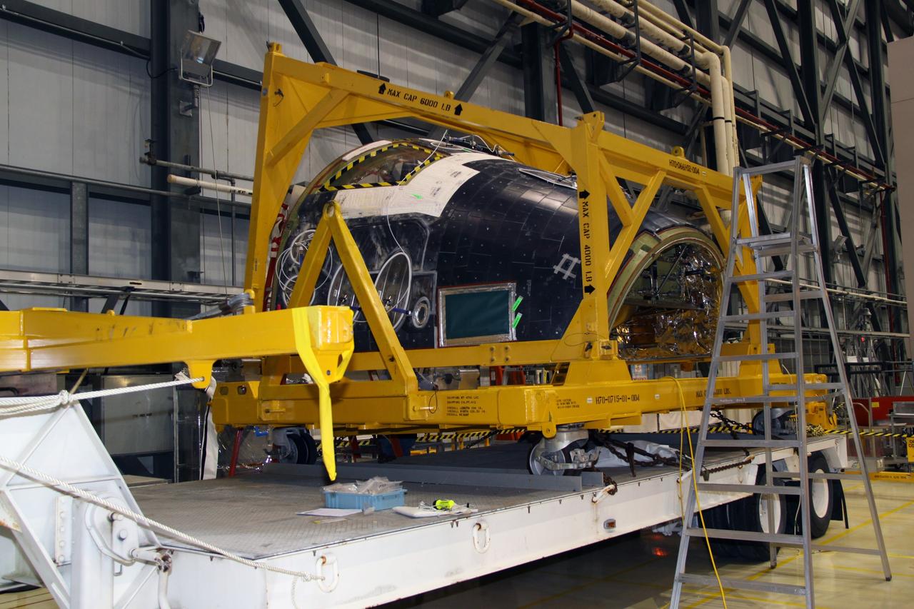
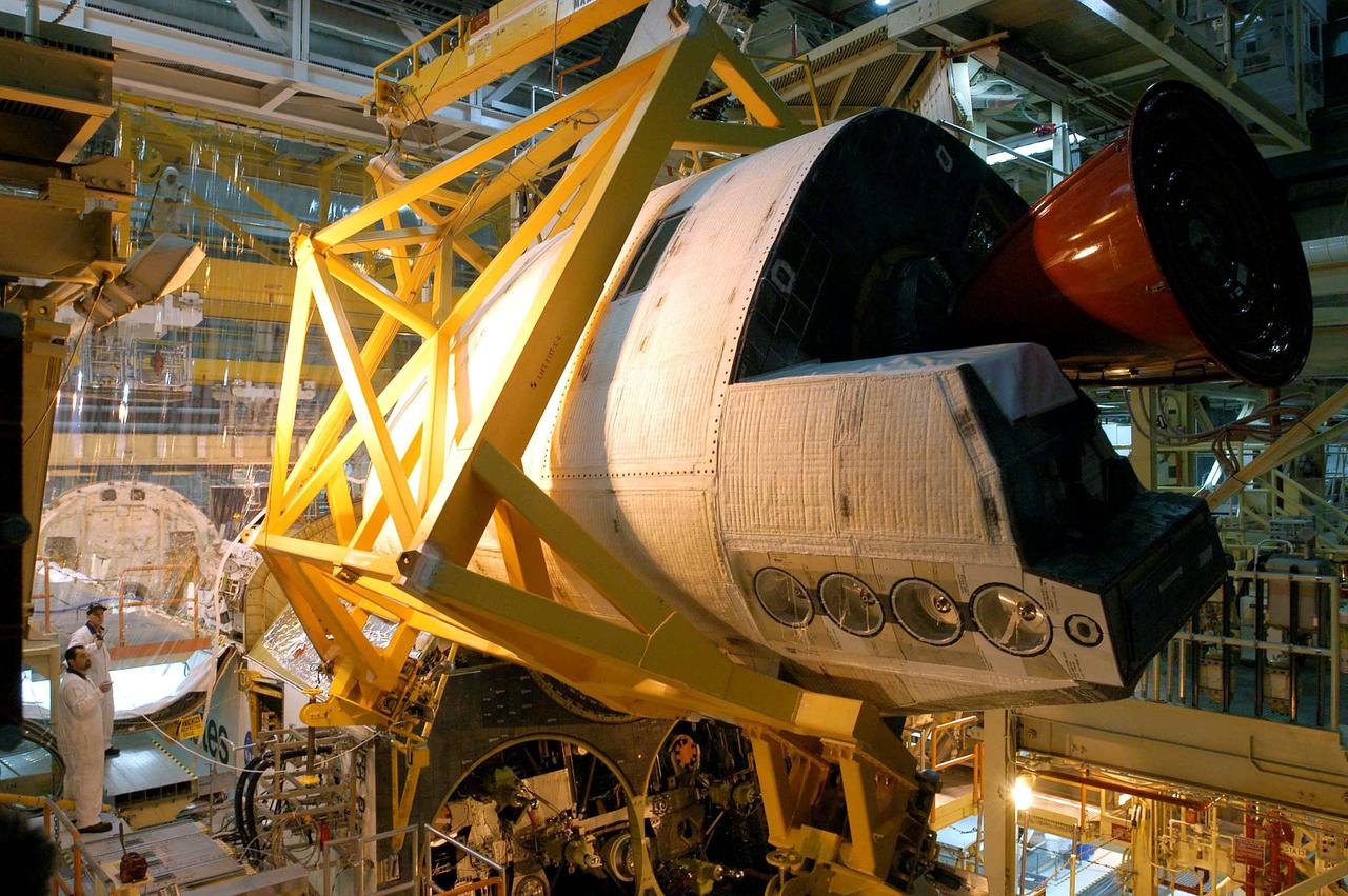
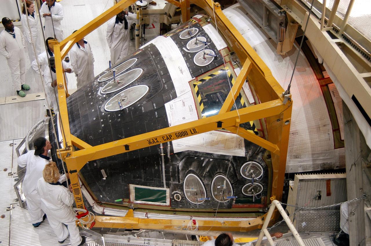
KENNEDY SPACE CENTER, FLA. - The Forward Reaction Control System (FRCS) of space shuttle Atlantis sits in the transfer aisle of Orbiter Processing Facility Bay 1 in anticipation of being installed. The FRCS provides the thrust for attitude (rotational) maneuvers (pitch, yaw and roll) and for small velocity changes along the orbiter axis (translation maneuvers). Processing of Atlantis is under way for mission STS-115, the 19th flight to the International Space Station.
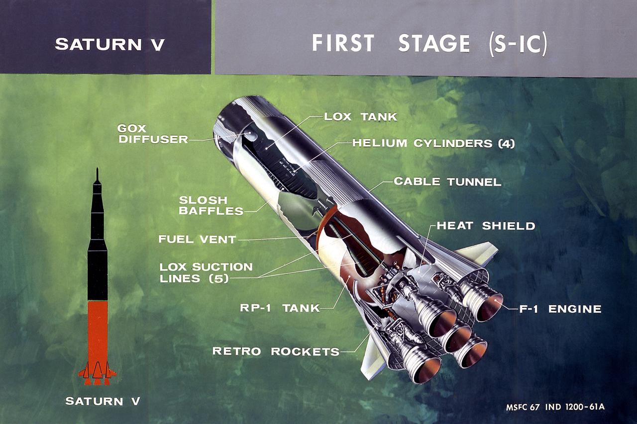
This illustration shows a cutaway drawing with callouts of the major components for the S-IC (first) stage of the Saturn V launch vehicle. The S-IC stage is 138 feet long and 33 feet in diameter, producing more than 7,500,000 pounds of thrust through five F-1 engines powered by liquid oxygen and kerosene. Four of the engines are mounted on an outer ring and gimball for control purposes. The fifth engine is rigidly mounted in the center. When ignited, the roar produced by the five engines equals the sound of 8,000,000 hi-fi sets.
KENNEDY SPACE CENTER, FLA. - In the Orbiter Processing Facility, the Forward Reaction Control System (FRCS) is lifted by an overhead crane for installation in Discovery. Located in the forward fuselage nose area, the FRCS provides the thrust for attitude (rotational) maneuvers (pitch, yaw and roll) and for small velocity changes along the orbiter axis (translation maneuvers). Discovery is designated as the Return to Flight vehicle for mission STS-114, no earlier than March 2005.
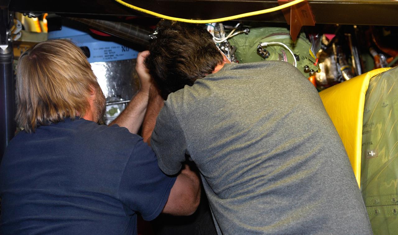
KENNEDY SPACE CENTER, FLA. - In Orbiter Processing Facility Bay 1, technicians work on the Forward Reaction Control System (FRCS) of space shuttle Atlantis as it sits in the transfer aisle prior to installation. The FRCS provides the thrust for attitude (rotational) maneuvers (pitch, yaw and roll) and for small velocity changes along the orbiter axis (translation maneuvers). Processing of Atlantis is under way for mission STS-115, the 19th flight to the International Space Station.
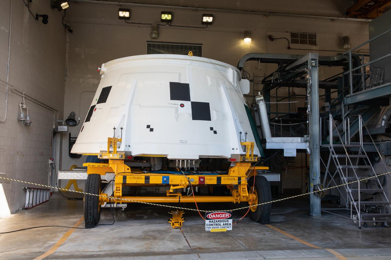
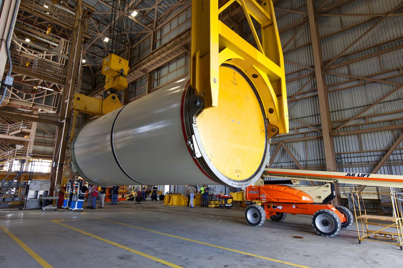
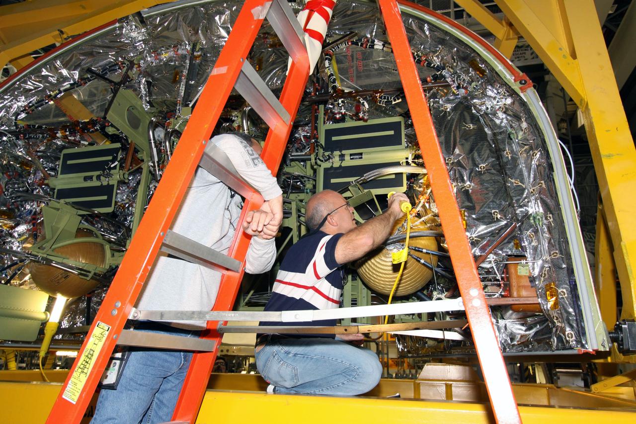
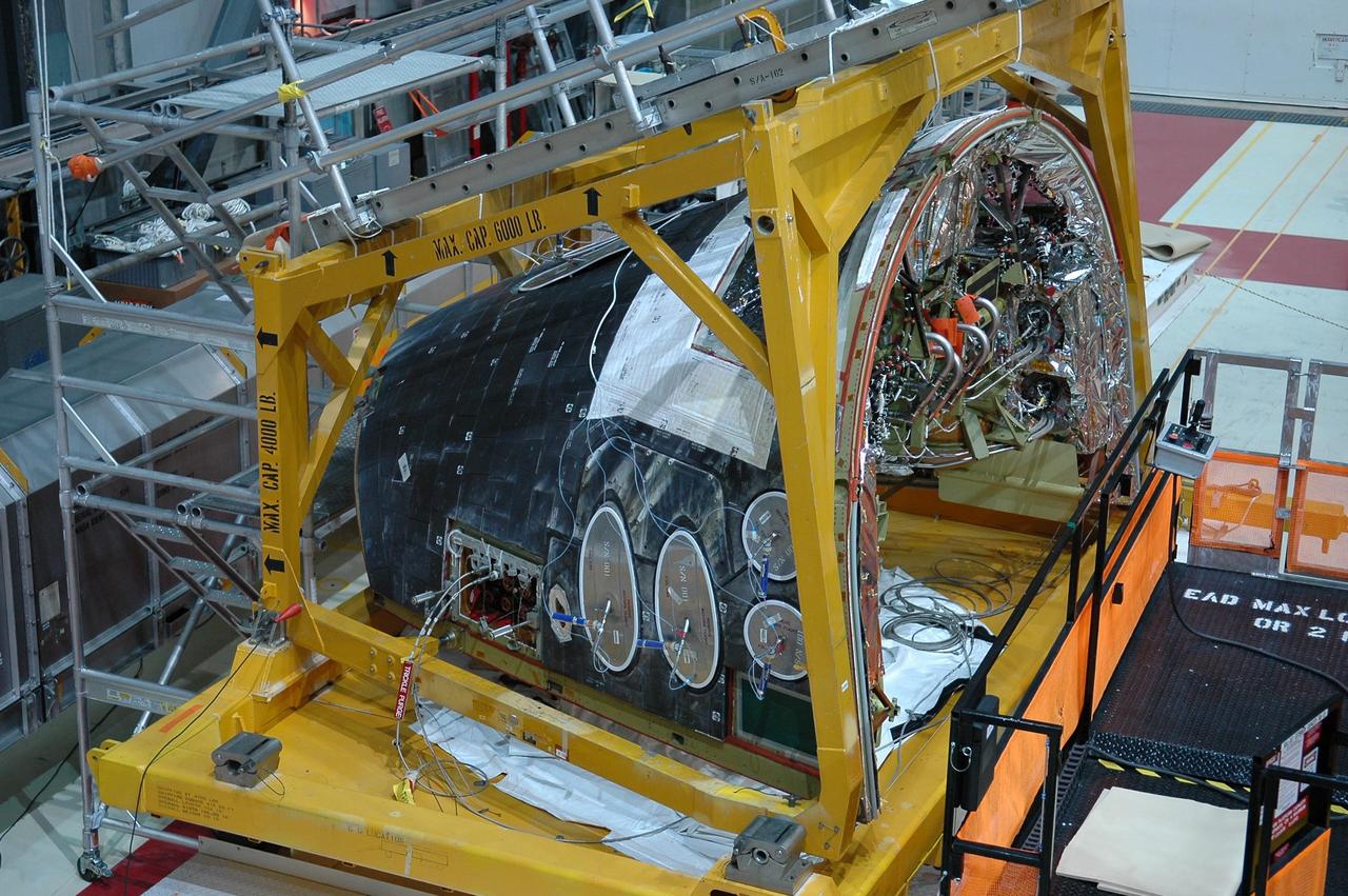
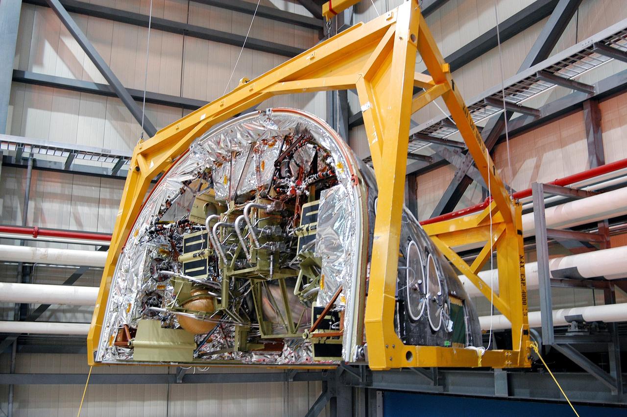
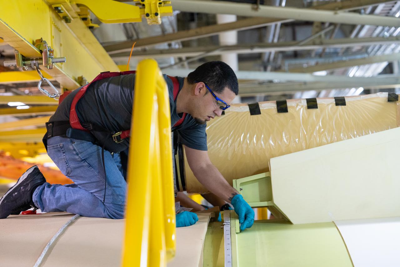
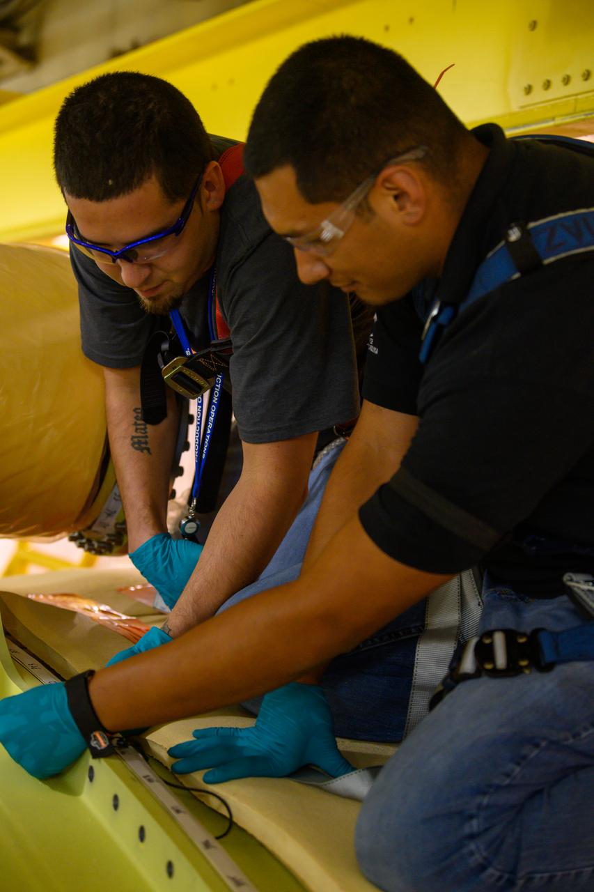
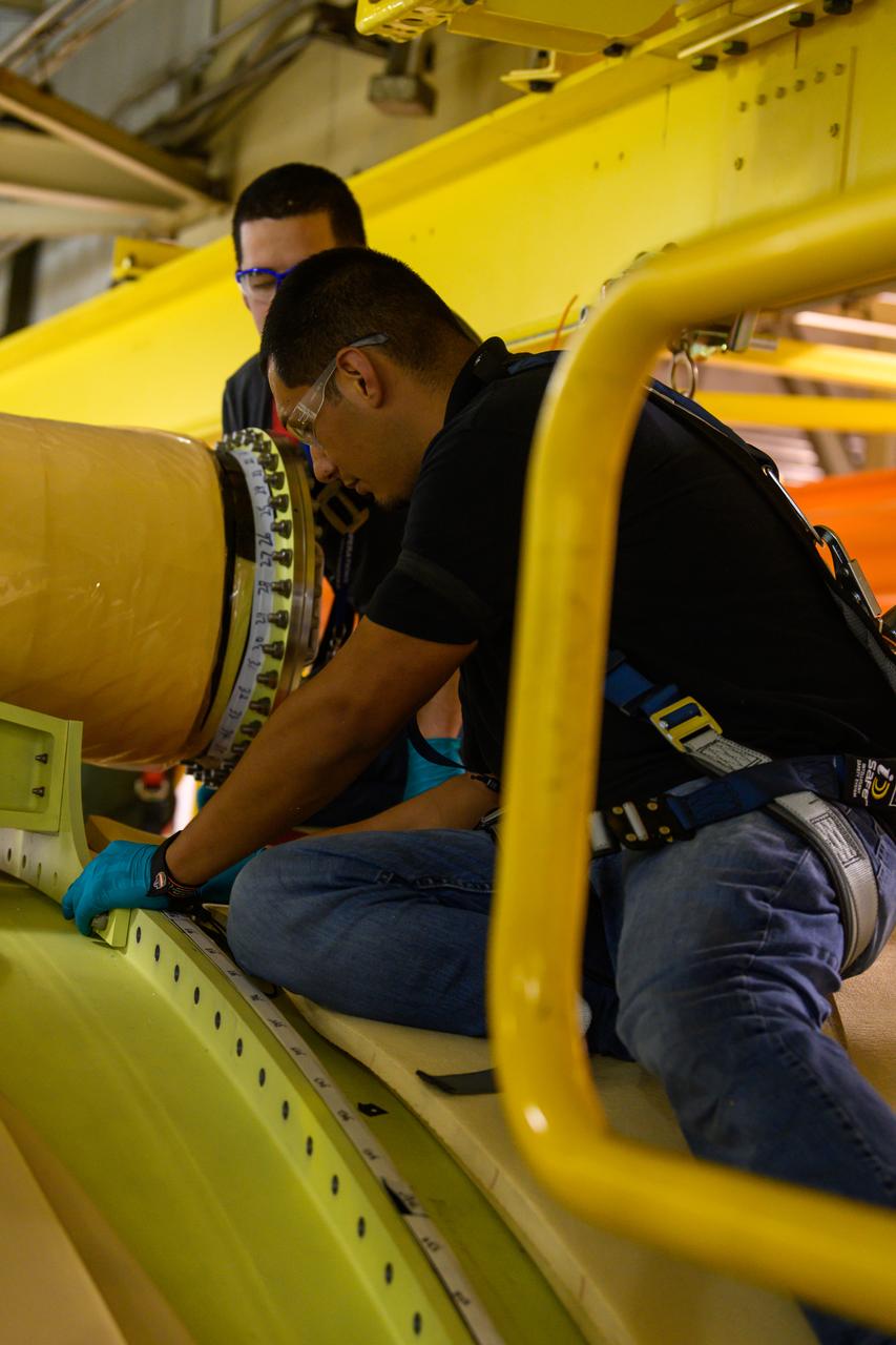
The aft skirt for one of the Space Launch System’s (SLS) two solid rocket boosters is inside the Booster Fabrication Facility at NASA’s Kennedy Space Center in Florida on Oct. 16, 2019. Segments of the boosters are being inspected and prepared for Artemis I, the agency’s first uncrewed flight of Orion atop the SLS. The aft skirts contain the thrust vector control system that steers the booster’s nozzles based on commands from the booster avionics during launch.
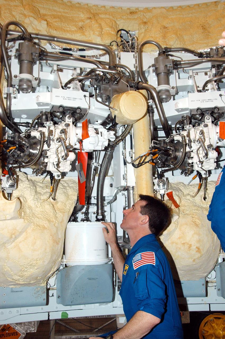
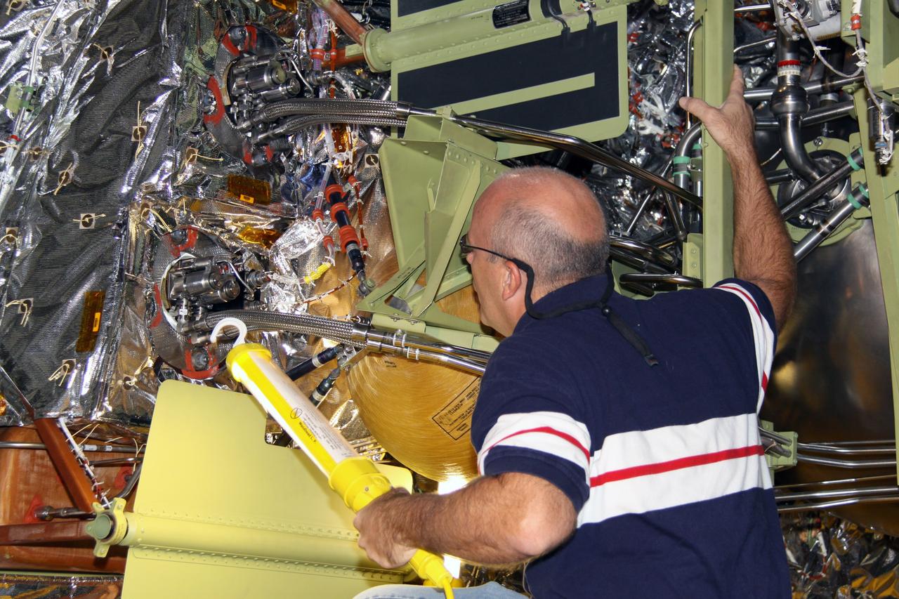
KENNEDY SPACE CENTER, FLA. - In the SRB Assembly and Refurbishment Facility, STS-114 Mission Specialist Stephen Robinson looks at part of the thrust vector control system in a segment of a solid rocket booster. The crew is at KSC for familiarization with Shuttle and mission equipment. The STS-114 mission is Logistics Flight 1, which is scheduled to deliver supplies and equipment, plus the external stowage platform, to the International Space Station.
KENNEDY SPACE CENTER, FLA. - In the Orbiter Processing Facility, the Forward Reaction Control System (FRCS) is lowered toward Discovery’s forward fuselage nose area where it will be installed. The FRCS provides the thrust for attitude (rotational) maneuvers (pitch, yaw and roll) and for small velocity changes along the orbiter axis (translation maneuvers). Discovery is designated as the Return to Flight vehicle for mission STS-114, no earlier than March 2005.
KENNEDY SPACE CENTER, FLA. - Workers in the Orbiter Processing Facility stand by as a crane lifts the Forward Reaction Control System (FRCS) for installation in Discovery. Located in the forward fuselage nose area, the FRCS provides the thrust for attitude (rotational) maneuvers (pitch, yaw and roll) and for small velocity changes along the orbiter axis (translation maneuvers). Discovery is designated as the Return to Flight vehicle for mission STS-114, no earlier than March 2005.

KENNEDY SPACE CENTER, FLA. - The Forward Reaction Control System (FRCS) of space shuttle Atlantis sits in the transfer aisle of Orbiter Processing Facility Bay 1 in anticipation of being installed. The FRCS provides the thrust for attitude (rotational) maneuvers (pitch, yaw and roll) and for small velocity changes along the orbiter axis (translation maneuvers). Processing of Atlantis is under way for mission STS-115, the 19th flight to the International Space Station.
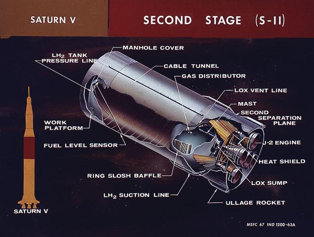
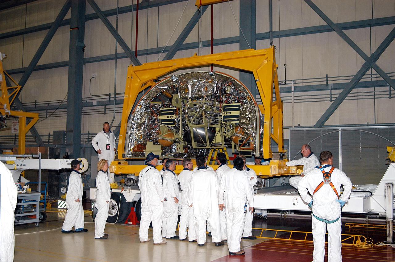
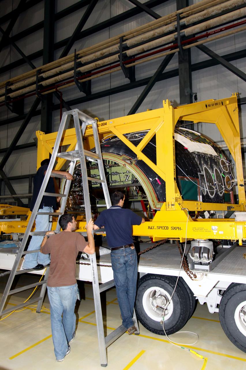
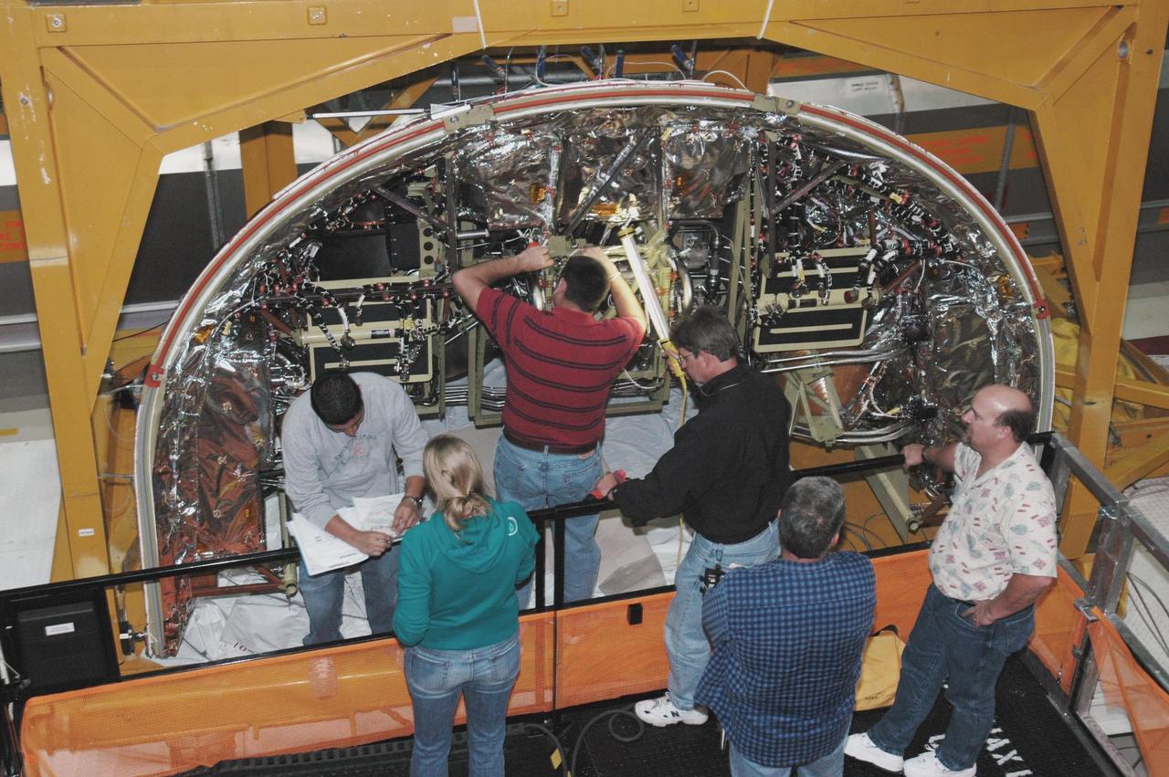
This cutaway illustration shows the Saturn V S-II (second) stage with callouts of major components. When the Saturn V first stage burns out and drops away, power for the Saturn was provided by the S-II (second) stage with five J-2 engines which produced a total of 1,150,000 pounds of thrust. Four outer engines are placed in a square pattern with gimbaling capability for control and guidance, with the fifth engine fixed rigidly in the center.
CAPE CANAVERAL, Fla. – In NASA Kennedy Space Center's Orbiter Processing Facility 2, workers prepare to remove the forward reaction control system, or FRCS, from space shuttle Endeavour's forward fuselage nose area. The FRCS provides the thrust for attitude (rotational) maneuvers (pitch, yaw and roll) and for small velocity changes along the orbiter axis (translation maneuvers). Endeavour is designated as the shuttle for the STS-130 mission, targeted for launch in February 2010. Photo credit: NASA/Jack Pfaller
KENNEDY SPACE CENTER, FLA. - In Orbiter Processing Facility Bay 1, technicians work on the Forward Reaction Control System (FRCS) of space shuttle Atlantis as it sits in the transfer aisle prior to installation. The FRCS provides the thrust for attitude (rotational) maneuvers (pitch, yaw and roll) and for small velocity changes along the orbiter axis (translation maneuvers). Processing of Atlantis is under way for mission STS-115, the 19th flight to the International Space Station.

KENNEDY SPACE CENTER, FLA. - The Forward Reaction Control System (FRCS) of space shuttle Atlantis sits in the transfer aisle of Orbiter Processing Facility Bay 1 in anticipation of being installed. The FRCS provides the thrust for attitude (rotational) maneuvers (pitch, yaw and roll) and for small velocity changes along the orbiter axis (translation maneuvers). Processing of Atlantis is under way for mission STS-115, the 19th flight to the International Space Station.
KENNEDY SPACE CENTER, FLA. - Workers in the Orbiter Processing Facility watch closely as Discovery’s Forward Reaction Control System (FRCS) is lowered into position in the orbiter’s forward fuselage nose area. The FRCS provides the thrust for attitude (rotational) maneuvers (pitch, yaw and roll) and for small velocity changes along the orbiter axis (translation maneuvers). Discovery is designated as the Return to Flight vehicle for mission STS-114, no earlier than March 2005.
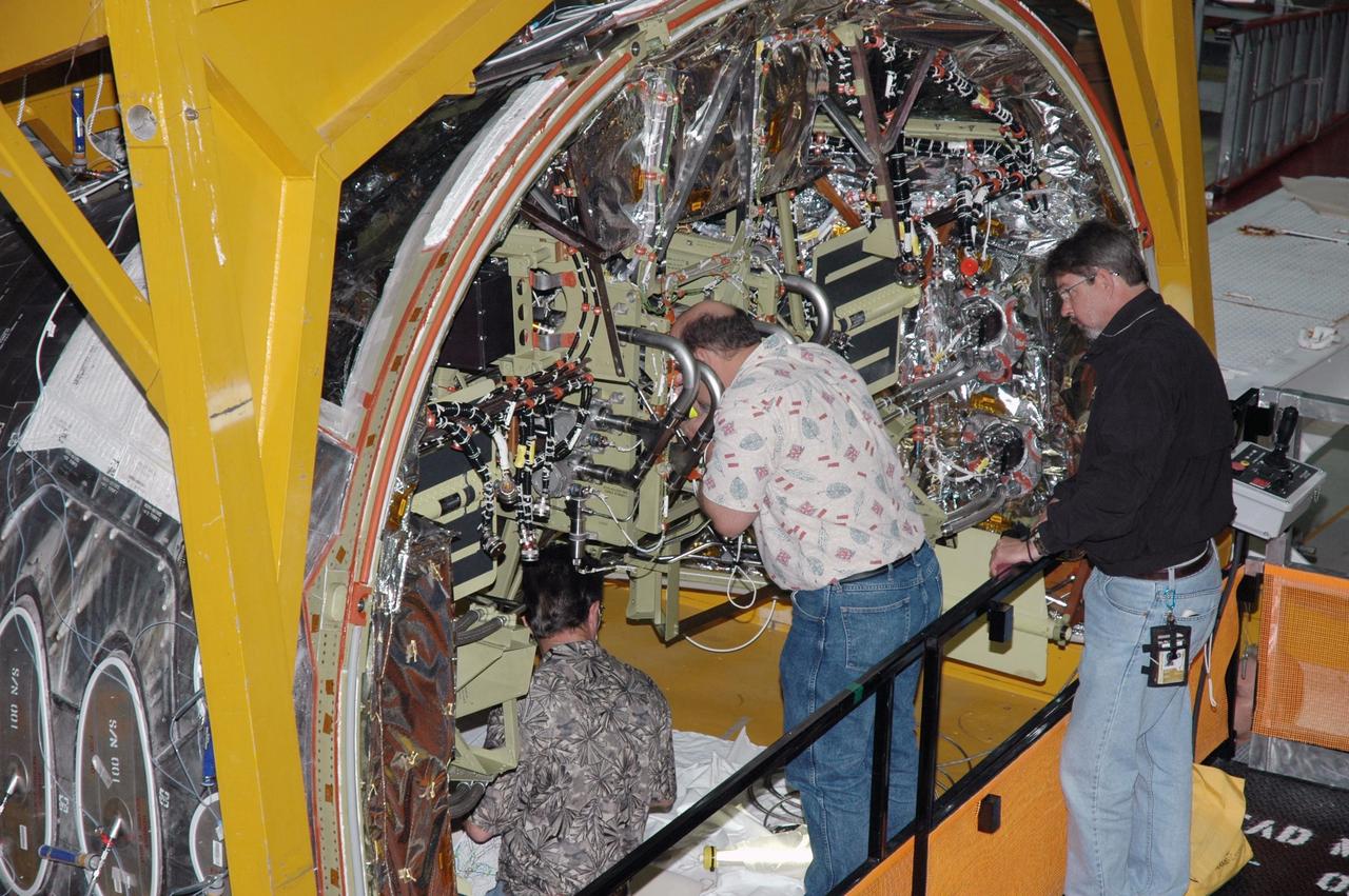
KENNEDY SPACE CENTER, FLA. - In Orbiter Processing Facility Bay 1, technicians work on the Forward Reaction Control System (FRCS) of space shuttle Atlantis as it sits in the transfer aisle prior to installation. The FRCS provides the thrust for attitude (rotational) maneuvers (pitch, yaw and roll) and for small velocity changes along the orbiter axis (translation maneuvers). Processing of Atlantis is under way for mission STS-115, the 19th flight to the International Space Station.
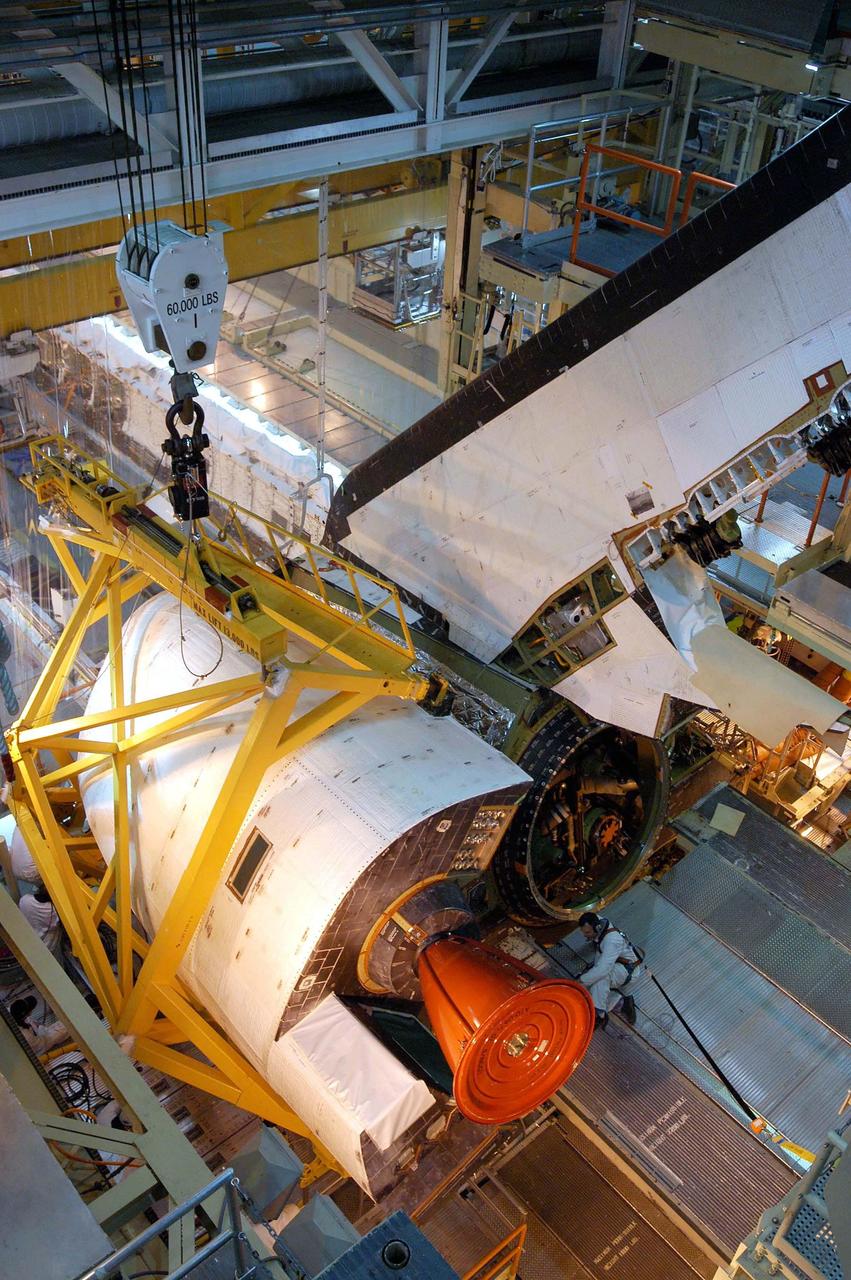
KENNEDY SPACE CENTER, FLA. - In the Orbiter Processing Facility, the left-hand Orbital Maneuvering System (OMS) pod is lowered toward the orbiter Discovery for installation. The Orbital Maneuvering System provides the thrust for orbit insertion, orbit circularization, orbit transfer, rendezvous, deorbit, abort to orbit and abort once around. It can provide up to 1,000 pounds of propellant to the aft reaction control system. Each pod contains one OMS engine and the hardware needed to pressurize, store and distribute the propellants to perform the velocity maneuvers.
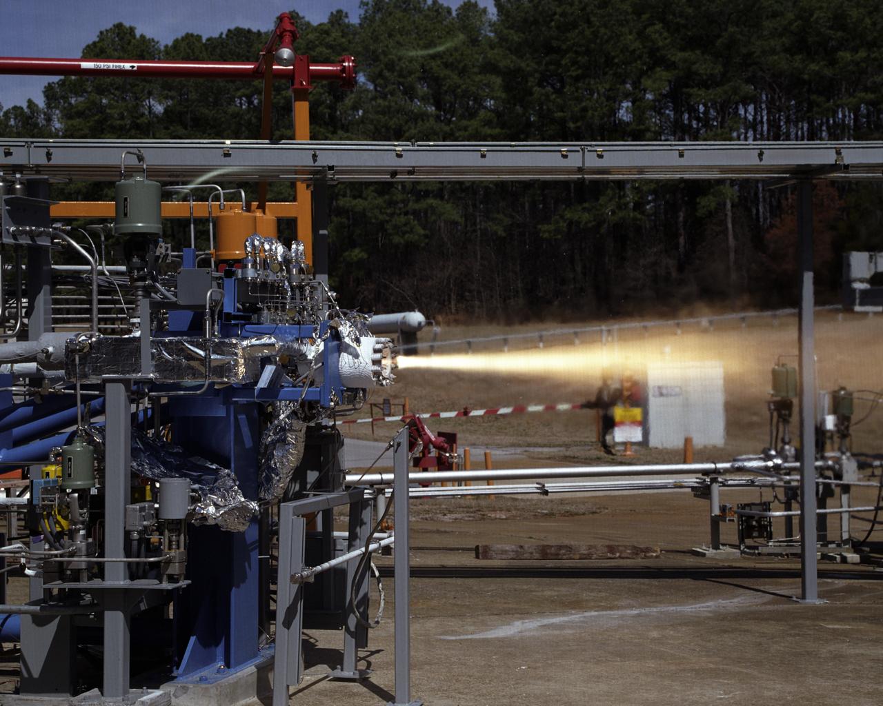
Jason Hopper of NASA (front row), Jody Ladner of Lockheed Martin (back row, left) and Chris Mulkey of NASA prepare to test the Blue Origin BE-3 engine thrust chamber in the E-1 Test Stand Control Center at John C. Stennis Space Center on Nov. 8. The test was one of 27 conducted in Stennis' E Test Complex the week of Nov. 5.

CAPE CANAVERAL, Fla. – In NASA Kennedy Space Center's Orbiter Processing Facility 2, workers remove the forward reaction control system, or FRCS, from space shuttle Endeavour's forward fuselage nose area. The FRCS provides the thrust for attitude (rotational) maneuvers (pitch, yaw and roll) and for small velocity changes along the orbiter axis (translation maneuvers). Endeavour is designated as the shuttle for the STS-130 mission, targeted for launch in February 2010. Photo credit: NASA/Jack Pfaller
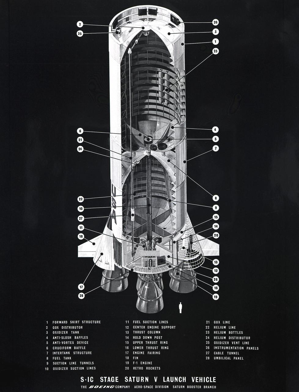
This cutaway illustration shows the Saturn V S-IC (first) stage with detailed callouts of the components. The S-IC Stage is 138 feet long and 33 feet in diameter, producing 7,500,000 pounds of thrust through five F-1 engines that are powered by liquid oxygen and kerosene. Four of the engines are mounted on an outer ring and gimbal for control purposes. The fifth engine is rigidly mounted in the center. When ignited, the roar produced by the five engines equals the sound of 8,000,000 hi-fi sets.
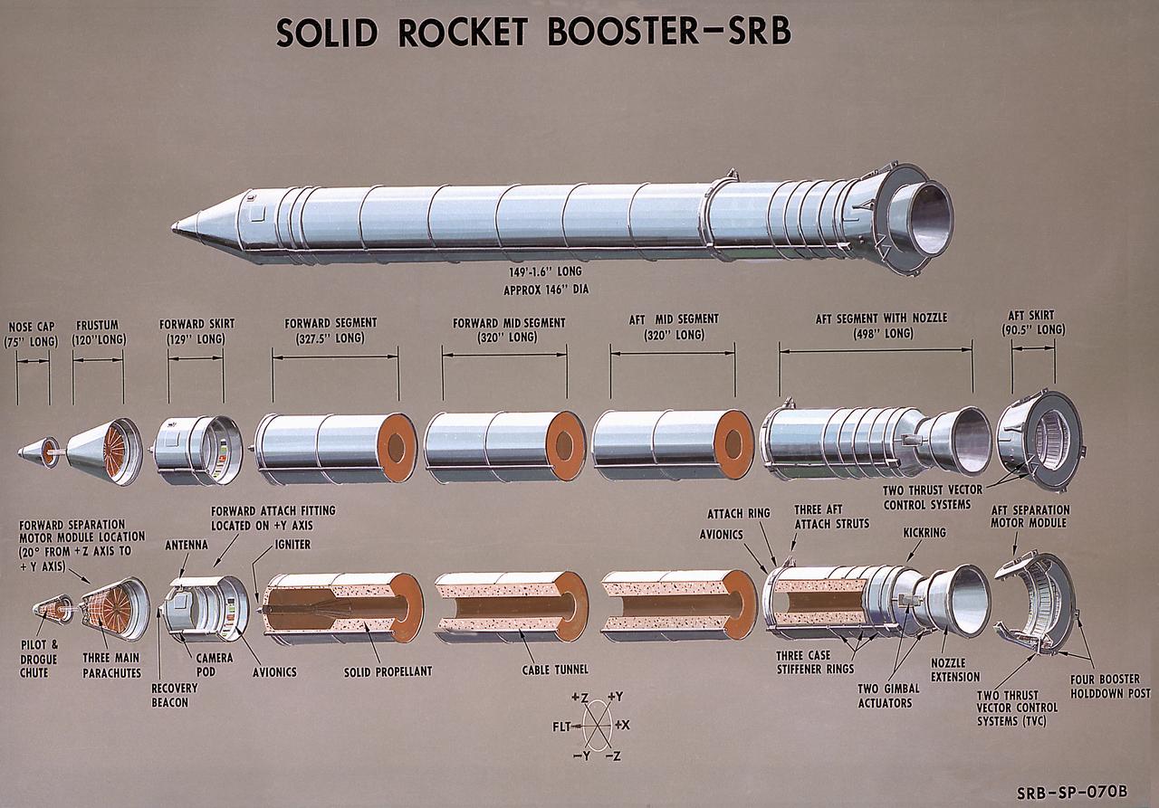
This illustration is a cutaway of the solid rocket booster (SRB) sections with callouts. The Shuttle's two SRB's are the largest solids ever built and the first designed for refurbishment and reuse. Standing nearly 150-feet high, the twin boosters provide the majority of thrust for the first two minutes of flight, about 5.8 million pounds, augmenting the Shuttle's main propulsion system during liftoff. The major design drivers for the solid rocket motors (SRM's) were high thrust and reuse. The desired thrust was achieved by using state-of-the-art solid propellant and by using a long cylindrical motor with a specific core design that allows the propellant to burn in a carefully controlled marner. At burnout, the boosters separate from the external tank and drop by parachute to the ocean for recovery and subsequent refurbishment. The boosters are designed to survive water impact at almost 60 miles per hour, maintain flotation with minimal damage, and preclude corrosion of the hardware exposed to the harsh seawater environment. Under the project management of the Marshall Space Flight Center, the SRB's are assembled and refurbished by the United Space Boosters. The SRM's are provided by the Morton Thiokol Corporation.
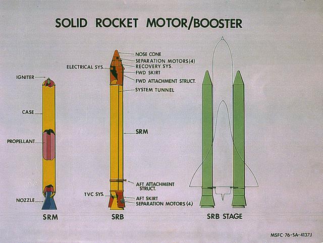
This image illustrates the solid rocket motor (SRM)/solid rocket booster (SRB) configuration. The Shuttle's two SRB's are the largest solids ever built and the first designed for refurbishment and reuse. Standing nearly 150-feet high, the twin boosters provide the majority of thrust for the first two minutes of flight, about 5.8 million pounds, augmenting the Shuttle's main propulsion system during liftoff. The major design drivers for the SRM's were high thrust and reuse. The desired thrust was achieved by using state-of-the-art solid propellant and by using a long cylindrical motor with a specific core design that allows the propellant to burn in a carefully controlled marner. At burnout, the boosters separate from the external tank and drop by parachute to the ocean for recovery and subsequent refurbishment. The boosters are designed to survive water impact at almost 60 miles per hour, maintain flotation with minimal damage, and preclude corrosion of the hardware exposed to the harsh seawater environment. Under the project management of the Marshall Space Flight Center, the SRB's are assembled and refurbished by the United Space Boosters. The SRM's are provided by the Morton Thiokol Corporation.
NASA finished assembling and joining the main structural components for the largest rocket stage the agency has built since the Saturn V that sent Apollo astronauts to the Moon. Engineers at the agency’s Michoud Assembly Facility in New Orleans connected the last of the five sections of the Space Launch System (SLS) rocket core stage Sept. 19. The stage will produce 2 million pounds of thrust to send Artemis I, the first flight SLS and NASA’s Orion spacecraft to the Moon. The engine section is located at the bottom of the 212-foot-tall stage and houses the four RS-25 engines. The core stage’s two liquid propellant tanks and four RS-25 engines will produce more than 2 million pounds of thrust to send the SLS rocket and Orion on the Artemis lunar missions. The engine section houses the four RS-25 engines and includes vital systems for mounting, controlling and delivering fuel form the propellant tanks to the rocket’s engines. Offering more payload mass, volume capability and energy to speed missions through space, the SLS rocket, along with NASA’s Gateway in lunar orbit and Orion, is part of NASA’s backbone for deep space exploration and the Artemis lunar program. No other rocket is capable of carrying astronauts in Orion around the Moon in a single mission.
NASA finished assembling and joining the main structural components for the largest rocket stage the agency has built since the Saturn V that sent Apollo astronauts to the Moon. Engineers at the agency’s Michoud Assembly Facility in New Orleans connected the last of the five sections of the Space Launch System (SLS) rocket core stage Sept. 19. The stage will produce 2 million pounds of thrust to send Artemis I, the first flight SLS and NASA’s Orion spacecraft to the Moon. The engine section is located at the bottom of the 212-foot-tall stage and houses the four RS-25 engines. The core stage’s two liquid propellant tanks and four RS-25 engines will produce more than 2 million pounds of thrust to send the SLS rocket and Orion on the Artemis lunar missions. The engine section houses the four RS-25 engines and includes vital systems for mounting, controlling and delivering fuel form the propellant tanks to the rocket’s engines. Offering more payload mass, volume capability and energy to speed missions through space, the SLS rocket, along with NASA’s Gateway in lunar orbit and Orion, is part of NASA’s backbone for deep space exploration and the Artemis lunar program. No other rocket is capable of carrying astronauts in Orion around the Moon in a single mission.
NASA finished assembling and joining the main structural components for the largest rocket stage the agency has built since the Saturn V that sent Apollo astronauts to the Moon. Engineers at the agency’s Michoud Assembly Facility in New Orleans connected the last of the five sections of the Space Launch System (SLS) rocket core stage Sept. 19. The stage will produce 2 million pounds of thrust to send Artemis I, the first flight SLS and NASA’s Orion spacecraft to the Moon. The engine section is located at the bottom of the 212-foot-tall stage and houses the four RS-25 engines. The core stage’s two liquid propellant tanks and four RS-25 engines will produce more than 2 million pounds of thrust to send the SLS rocket and Orion on the Artemis lunar missions. The engine section houses the four RS-25 engines and includes vital systems for mounting, controlling and delivering fuel form the propellant tanks to the rocket’s engines. Offering more payload mass, volume capability and energy to speed missions through space, the SLS rocket, along with NASA’s Gateway in lunar orbit and Orion, is part of NASA’s backbone for deep space exploration and the Artemis lunar program. No other rocket is capable of carrying astronauts in Orion around the Moon in a single mission.
NASA finished assembling and joining the main structural components for the largest rocket stage the agency has built since the Saturn V that sent Apollo astronauts to the Moon. Engineers at the agency’s Michoud Assembly Facility in New Orleans connected the last of the five sections of the Space Launch System (SLS) rocket core stage Sept. 19. The stage will produce 2 million pounds of thrust to send Artemis I, the first flight SLS and NASA’s Orion spacecraft to the Moon. The engine section is located at the bottom of the 212-foot-tall stage and houses the four RS-25 engines. The core stage’s two liquid propellant tanks and four RS-25 engines will produce more than 2 million pounds of thrust to send the SLS rocket and Orion on the Artemis lunar missions. The engine section houses the four RS-25 engines and includes vital systems for mounting, controlling and delivering fuel form the propellant tanks to the rocket’s engines. Offering more payload mass, volume capability and energy to speed missions through space, the SLS rocket, along with NASA’s Gateway in lunar orbit and Orion, is part of NASA’s backbone for deep space exploration and the Artemis lunar program. No other rocket is capable of carrying astronauts in Orion around the Moon in a single mission.
NASA finished assembling and joining the main structural components for the largest rocket stage the agency has built since the Saturn V that sent Apollo astronauts to the Moon. Engineers at the agency’s Michoud Assembly Facility in New Orleans connected the last of the five sections of the Space Launch System (SLS) rocket core stage Sept. 19. The stage will produce 2 million pounds of thrust to send Artemis I, the first flight SLS and NASA’s Orion spacecraft to the Moon. The engine section is located at the bottom of the 212-foot-tall stage and houses the four RS-25 engines. The core stage’s two liquid propellant tanks and four RS-25 engines will produce more than 2 million pounds of thrust to send the SLS rocket and Orion on the Artemis lunar missions. The engine section houses the four RS-25 engines and includes vital systems for mounting, controlling and delivering fuel form the propellant tanks to the rocket’s engines. Offering more payload mass, volume capability and energy to speed missions through space, the SLS rocket, along with NASA’s Gateway in lunar orbit and Orion, is part of NASA’s backbone for deep space exploration and the Artemis lunar program. No other rocket is capable of carrying astronauts in Orion around the Moon in a single mission.
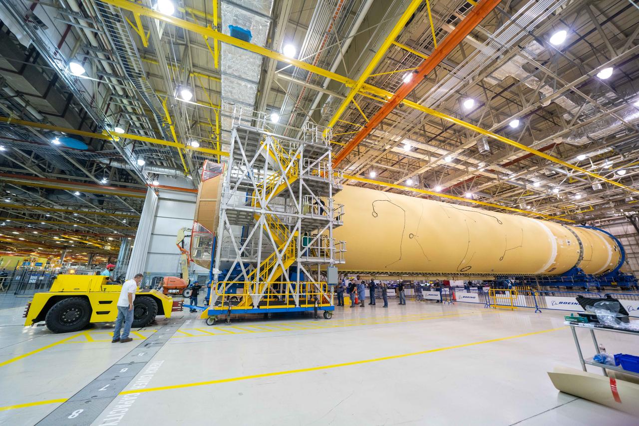
NASA finished assembling and joining the main structural components for the largest rocket stage the agency has built since the Saturn V that sent Apollo astronauts to the Moon. Engineers at the agency’s Michoud Assembly Facility in New Orleans connected the last of the five sections of the Space Launch System (SLS) rocket core stage Sept. 19. The stage will produce 2 million pounds of thrust to send Artemis I, the first flight SLS and NASA’s Orion spacecraft to the Moon. The engine section is located at the bottom of the 212-foot-tall stage and houses the four RS-25 engines. The core stage’s two liquid propellant tanks and four RS-25 engines will produce more than 2 million pounds of thrust to send the SLS rocket and Orion on the Artemis lunar missions. The engine section houses the four RS-25 engines and includes vital systems for mounting, controlling and delivering fuel form the propellant tanks to the rocket’s engines. Offering more payload mass, volume capability and energy to speed missions through space, the SLS rocket, along with NASA’s Gateway in lunar orbit and Orion, is part of NASA’s backbone for deep space exploration and the Artemis lunar program. No other rocket is capable of carrying astronauts in Orion around the Moon in a single mission.