NASA will demonstrate high-risk, high-payoff technology advancements critical for U.S. aerospace manufacturers to bring to market innovative, cost-effective, and sustainable products and services demanded by airlines and customers.

This is the 3rd entry of the TTBW model in 14x22. This test specifically is a lateral-directional test looking at the effects of 3D printed ventral, keel, and dorsal strakes on the stability and control characteristics of the model. Cooperative agreement between Boeing and NASA.
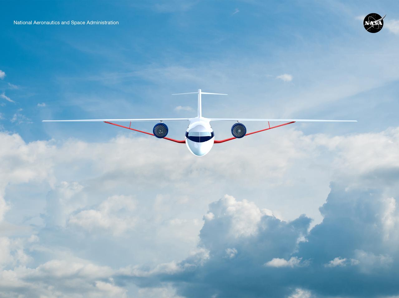
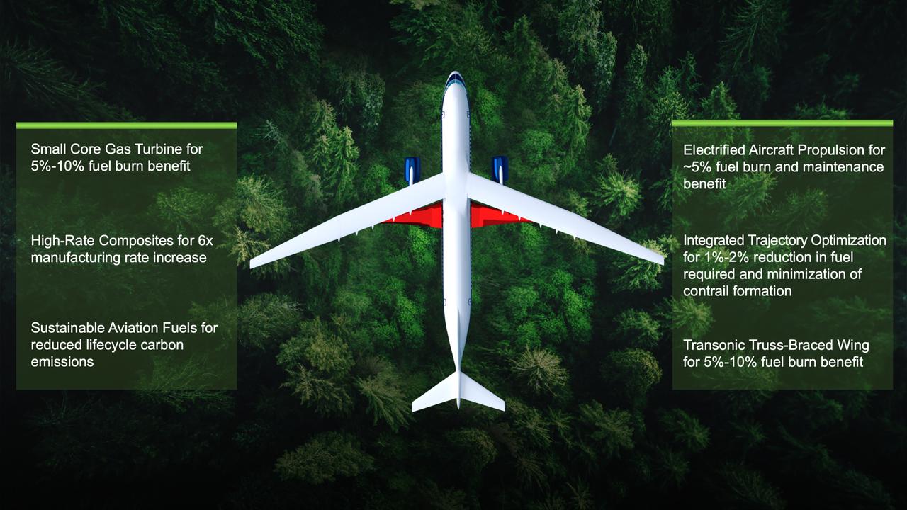
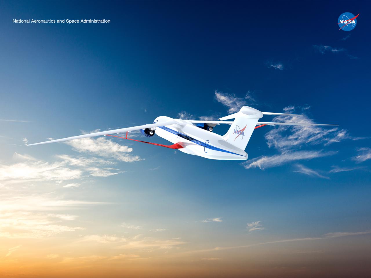
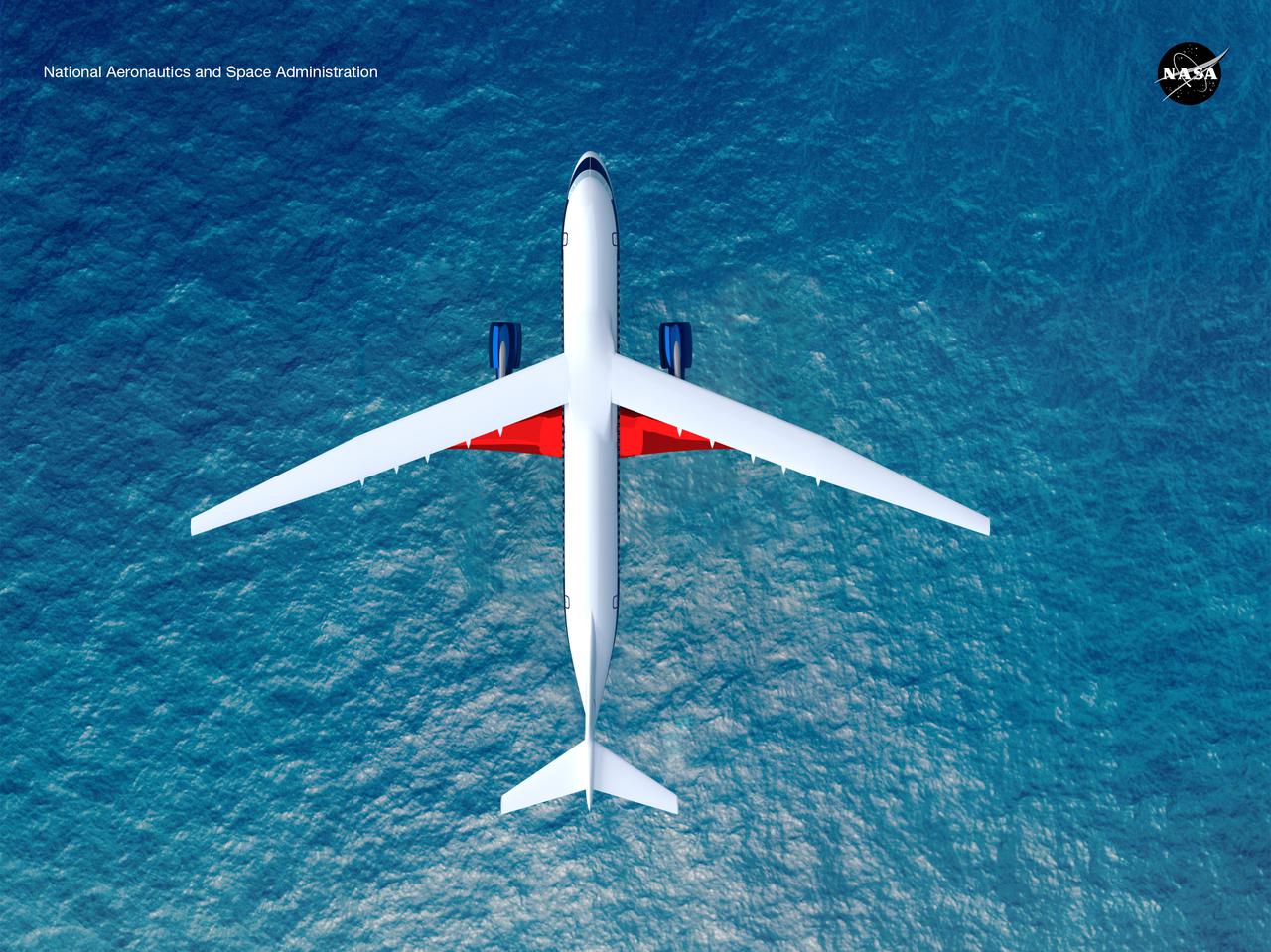
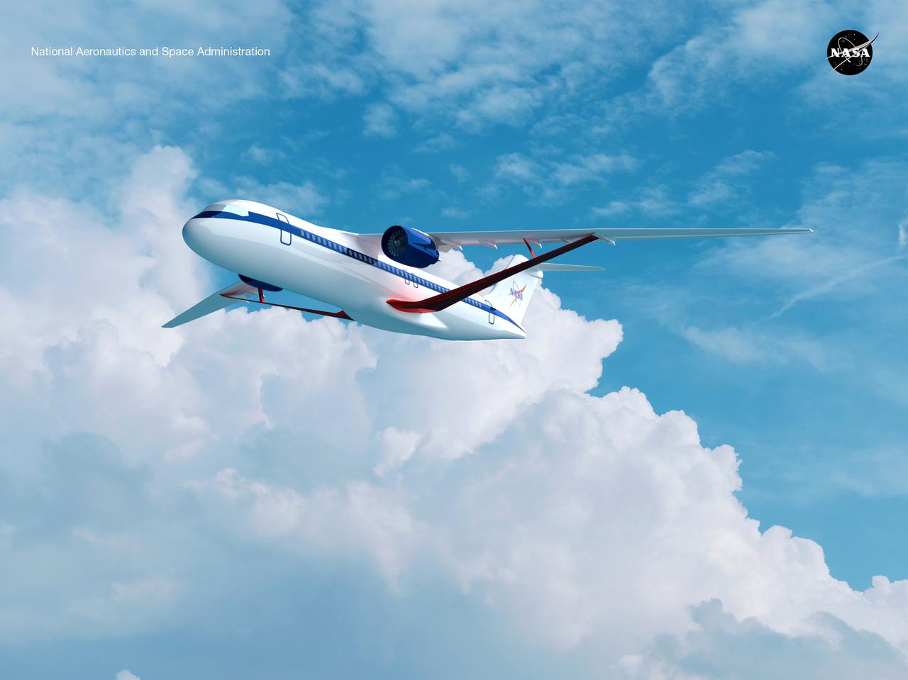
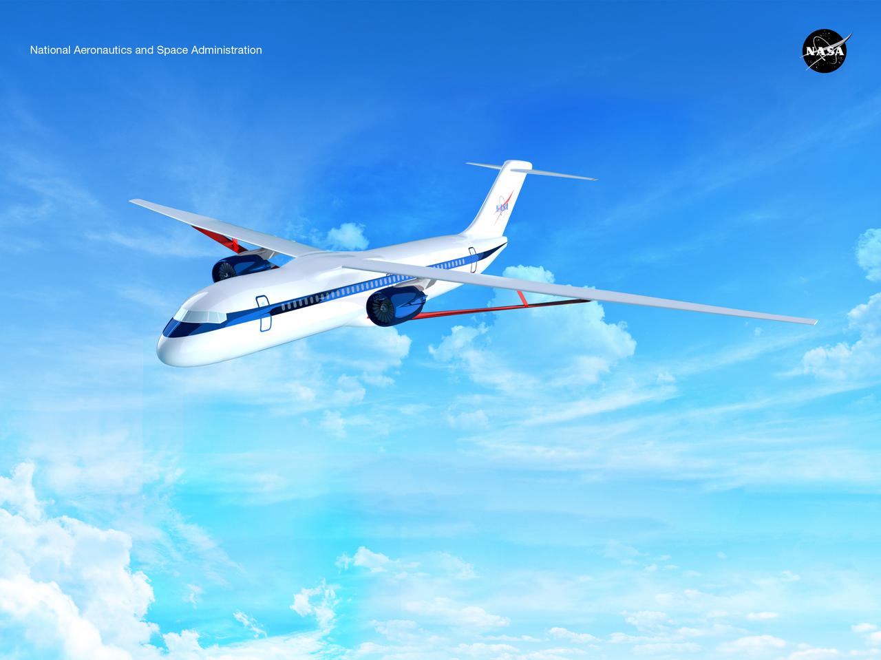
Notice anything different about the wings on this airliner? This conceptual truss-braced wing narrowbody is an aircraft with a 170ft span folding wing. By utilizing trusses, the aircraft can have longer, thinner wings with greater aspect ratios. This, in turn, translates into less drag and 5-10% less fuel burned. The Transonic Truss-Braced Wing aircraft originated from a joint effort by NASA and Boeing to develop subsonic commercial transport concepts – meeting NASA-defined metrics in terms of reduced noise, emissions, and fuel consumption. The design is currently undergoing wind tunnel testing and other studies by NASA researchers.
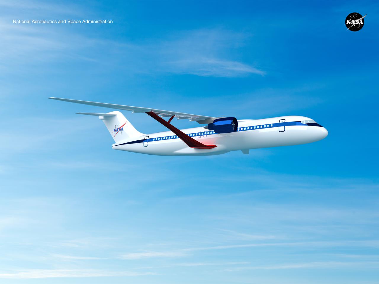
Notice anything different about the wings on this airliner? This conceptual truss-braced wing narrowbody is an aircraft with a 170ft span folding wing. By utilizing trusses, the aircraft can have longer, thinner wings with greater aspect ratios. This, in turn, translates into less drag and 5-10% less fuel burned. The Transonic Truss-Braced Wing aircraft originated from a joint effort by NASA and Boeing to develop subsonic commercial transport concepts – meeting NASA-defined metrics in terms of reduced noise, emissions, and fuel consumption. The design is currently undergoing wind tunnel testing and other studies by NASA researchers.
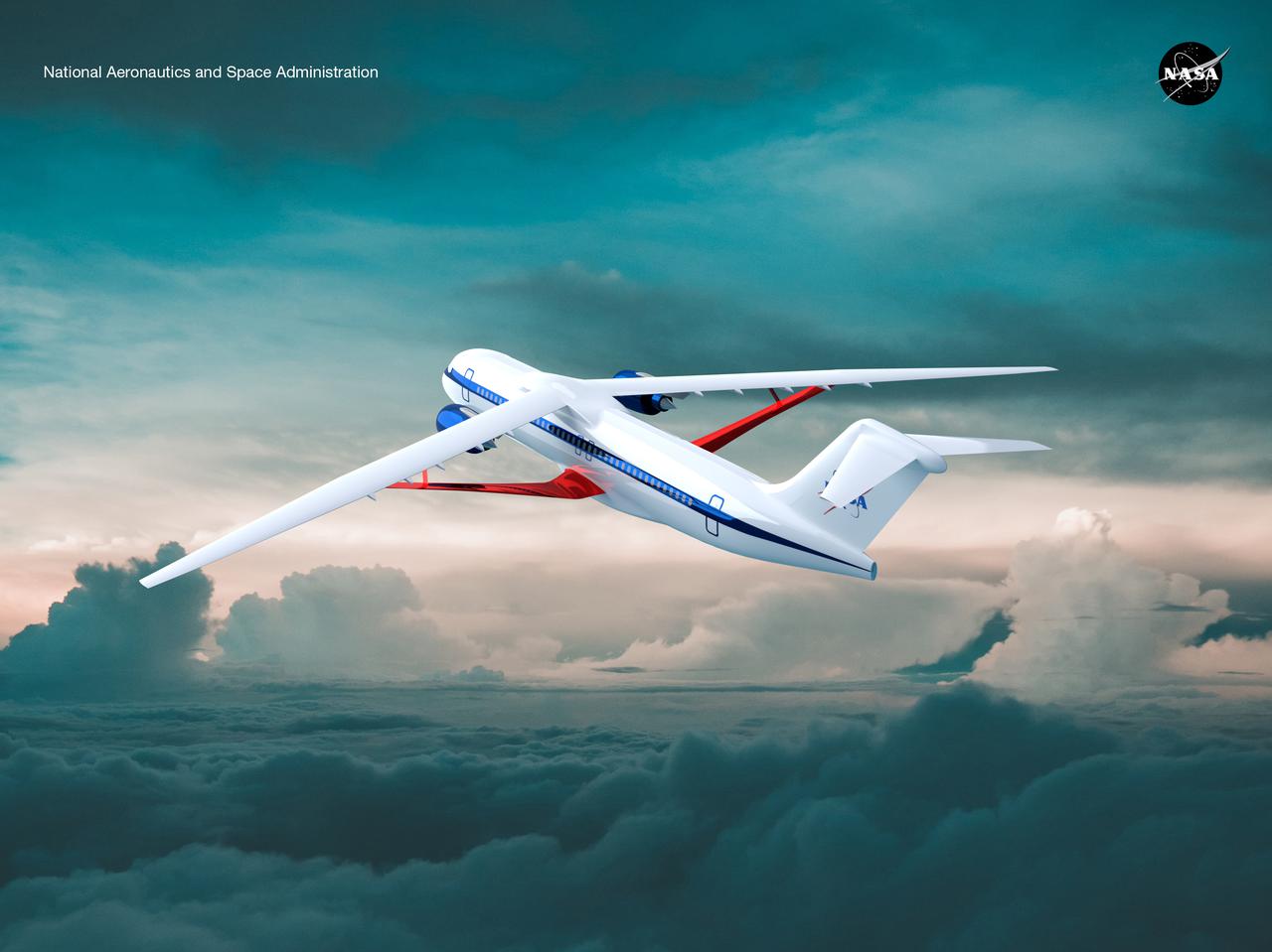
Notice anything different about the wings on this airliner? This conceptual truss-braced wing narrowbody is an aircraft with a 170ft span folding wing. By utilizing trusses, the aircraft can have longer, thinner wings with greater aspect ratios. This, in turn, translates into less drag and 5-10% less fuel burned. The Transonic Truss-Braced Wing aircraft originated from a joint effort by NASA and Boeing to develop subsonic commercial transport concepts – meeting NASA-defined metrics in terms of reduced noise, emissions, and fuel consumption. The design is currently undergoing wind tunnel testing and other studies by NASA researchers.
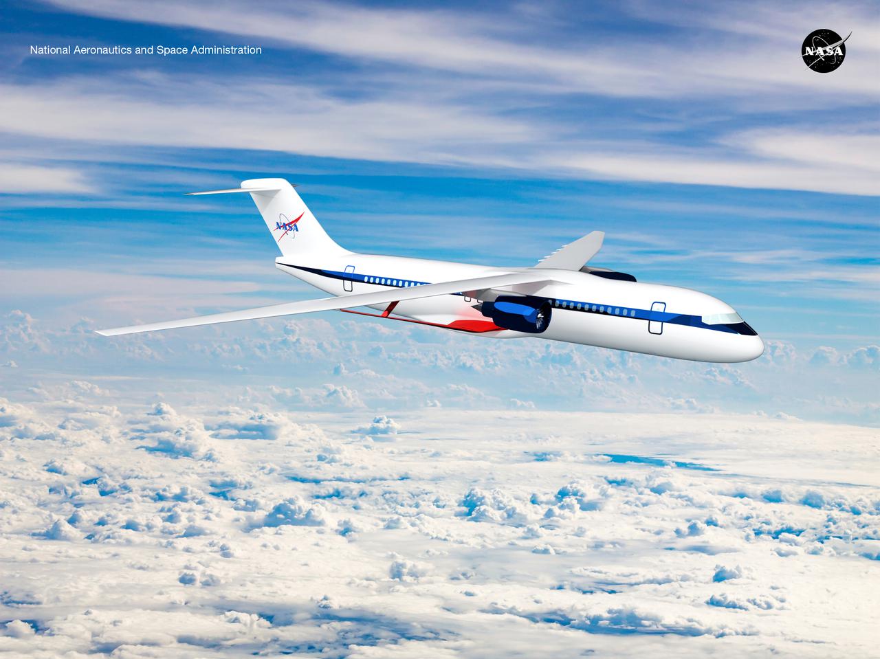
An artist’s concept of the transonic truss-braced wing aircraft configuration in flight over a forest of trees.
An artist’s concept of the transonic truss-braced wing aircraft configuration in flight over a forest of trees.
Notice anything different about the wings on this airliner? This conceptual truss-braced wing narrowbody is an aircraft with a 170ft span folding wing. By utilizing trusses, the aircraft can have longer, thinner wings with greater aspect ratios. This, in turn, translates into less drag and 5-10% less fuel burned. The Transonic Truss-Braced Wing aircraft originated from a joint effort by NASA and Boeing to develop subsonic commercial transport concepts – meeting NASA-defined metrics in terms of reduced noise, emissions, and fuel consumption. The design is currently undergoing wind tunnel testing and other studies by NASA researchers.
Notice anything different about the wings on this airliner? This conceptual truss-braced wing narrowbody is an aircraft with a 170ft span folding wing. By utilizing trusses, the aircraft can have longer, thinner wings with greater aspect ratios. This, in turn, translates into less drag and 5-10% less fuel burned. The Transonic Truss-Braced Wing aircraft originated from a joint effort by NASA and Boeing to develop subsonic commercial transport concepts – meeting NASA-defined metrics in terms of reduced noise, emissions, and fuel consumption. The design is currently undergoing wind tunnel testing and other studies by NASA researchers.
Notice anything different about the wings on this airliner? This conceptual truss-braced wing narrowbody is an aircraft with a 170ft span folding wing. By utilizing trusses, the aircraft can have longer, thinner wings with greater aspect ratios. This, in turn, translates into less drag and 5-10% less fuel burned. The Transonic Truss-Braced Wing aircraft originated from a joint effort by NASA and Boeing to develop subsonic commercial transport concepts – meeting NASA-defined metrics in terms of reduced noise, emissions, and fuel consumption. The design is currently undergoing wind tunnel testing and other studies by NASA researchers.
Notice anything different about the wings on this airliner? This conceptual truss-braced wing narrowbody is an aircraft with a 170ft span folding wing. By utilizing trusses, the aircraft can have longer, thinner wings with greater aspect ratios. This, in turn, translates into less drag and 5-10% less fuel burned. The Transonic Truss-Braced Wing aircraft originated from a joint effort by NASA and Boeing to develop subsonic commercial transport concepts – meeting NASA-defined metrics in terms of reduced noise, emissions, and fuel consumption. The design is currently undergoing wind tunnel testing and other studies by NASA researchers.
Notice anything different about the wings on this airliner? This conceptual truss-braced wing narrowbody is an aircraft with a 170ft span folding wing. By utilizing trusses, the aircraft can have longer, thinner wings with greater aspect ratios. This, in turn, translates into less drag and 5-10% less fuel burned. The Transonic Truss-Braced Wing aircraft originated from a joint effort by NASA and Boeing to develop subsonic commercial transport concepts – meeting NASA-defined metrics in terms of reduced noise, emissions, and fuel consumption. The design is currently undergoing wind tunnel testing and other studies by NASA researchers.
Notice anything different about the wings on this airliner? This conceptual truss-braced wing narrowbody is an aircraft with a 170ft span folding wing. By utilizing trusses, the aircraft can have longer, thinner wings with greater aspect ratios. This, in turn, translates into less drag and 5-10% less fuel burned. The Transonic Truss-Braced Wing aircraft originated from a joint effort by NASA and Boeing to develop subsonic commercial transport concepts – meeting NASA-defined metrics in terms of reduced noise, emissions, and fuel consumption. The design is currently undergoing wind tunnel testing and other studies by NASA researchers.
Notice anything different about the wings on this airliner? This conceptual truss-braced wing narrowbody is an aircraft with a 170ft span folding wing. By utilizing trusses, the aircraft can have longer, thinner wings with greater aspect ratios. This, in turn, translates into less drag and 5-10% less fuel burned. The Transonic Truss-Braced Wing aircraft originated from a joint effort by NASA and Boeing to develop subsonic commercial transport concepts – meeting NASA-defined metrics in terms of reduced noise, emissions, and fuel consumption. The design is currently undergoing wind tunnel testing and other studies by NASA researchers.
Notice anything different about the wings on this airliner? This conceptual truss-braced wing narrowbody is an aircraft with a 170ft span folding wing. By utilizing trusses, the aircraft can have longer, thinner wings with greater aspect ratios. This, in turn, translates into less drag and 5-10% less fuel burned. The Transonic Truss-Braced Wing aircraft originated from a joint effort by NASA and Boeing to develop subsonic commercial transport concepts – meeting NASA-defined metrics in terms of reduced noise, emissions, and fuel consumption. The design is currently undergoing wind tunnel testing and other studies by NASA researchers.
Notice anything different about the wings on this airliner? This conceptual truss-braced wing narrowbody is an aircraft with a 170ft span folding wing. By utilizing trusses, the aircraft can have longer, thinner wings with greater aspect ratios. This, in turn, translates into less drag and 5-10% less fuel burned. The Transonic Truss-Braced Wing aircraft originated from a joint effort by NASA and Boeing to develop subsonic commercial transport concepts – meeting NASA-defined metrics in terms of reduced noise, emissions, and fuel consumption. The design is currently undergoing wind tunnel testing and other studies by NASA researchers.
Notice anything different about the wings on this airliner? This conceptual truss-braced wing narrowbody is an aircraft with a 170ft span folding wing. By utilizing trusses, the aircraft can have longer, thinner wings with greater aspect ratios. This, in turn, translates into less drag and 5-10% less fuel burned. The Transonic Truss-Braced Wing aircraft originated from a joint effort by NASA and Boeing to develop subsonic commercial transport concepts – meeting NASA-defined metrics in terms of reduced noise, emissions, and fuel consumption. The design is currently undergoing wind tunnel testing and other studies by NASA researchers.
Notice anything different about the wings on this airliner? This conceptual truss-braced wing narrowbody is an aircraft with a 170ft span folding wing. By utilizing trusses, the aircraft can have longer, thinner wings with greater aspect ratios. This, in turn, translates into less drag and 5-10% less fuel burned. The Transonic Truss-Braced Wing aircraft originated from a joint effort by NASA and Boeing to develop subsonic commercial transport concepts – meeting NASA-defined metrics in terms of reduced noise, emissions, and fuel consumption. The design is currently undergoing wind tunnel testing and other studies by NASA researchers.
Notice anything different about the wings on this airliner? This conceptual truss-braced wing narrowbody is an aircraft with a 170ft span folding wing. By utilizing trusses, the aircraft can have longer, thinner wings with greater aspect ratios. This, in turn, translates into less drag and 5-10% less fuel burned. The Transonic Truss-Braced Wing aircraft originated from a joint effort by NASA and Boeing to develop subsonic commercial transport concepts – meeting NASA-defined metrics in terms of reduced noise, emissions, and fuel consumption. The design is currently undergoing wind tunnel testing and other studies by NASA researchers.
Notice anything different about the wings on this airliner? This conceptual truss-braced wing narrowbody is an aircraft with a 170ft span folding wing. By utilizing trusses, the aircraft can have longer, thinner wings with greater aspect ratios. This, in turn, translates into less drag and 5-10% less fuel burned. The Transonic Truss-Braced Wing aircraft originated from a joint effort by NASA and Boeing to develop subsonic commercial transport concepts – meeting NASA-defined metrics in terms of reduced noise, emissions, and fuel consumption. The design is currently undergoing wind tunnel testing and other studies by NASA researchers.
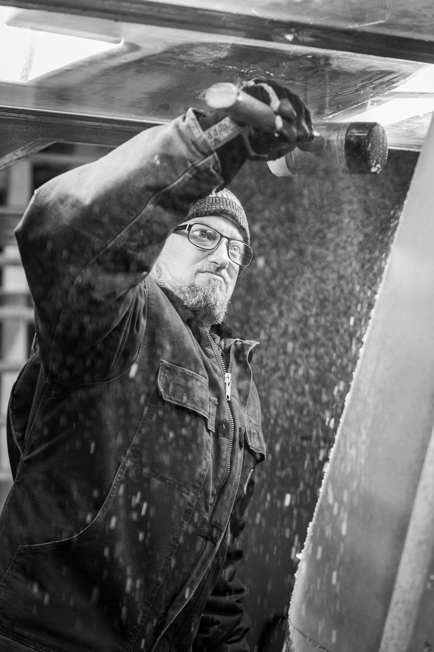
A technician is shown preparing the research model for its next test condition by removing ice accretion. Photo Credit: (NASA/Jordan Salkin)
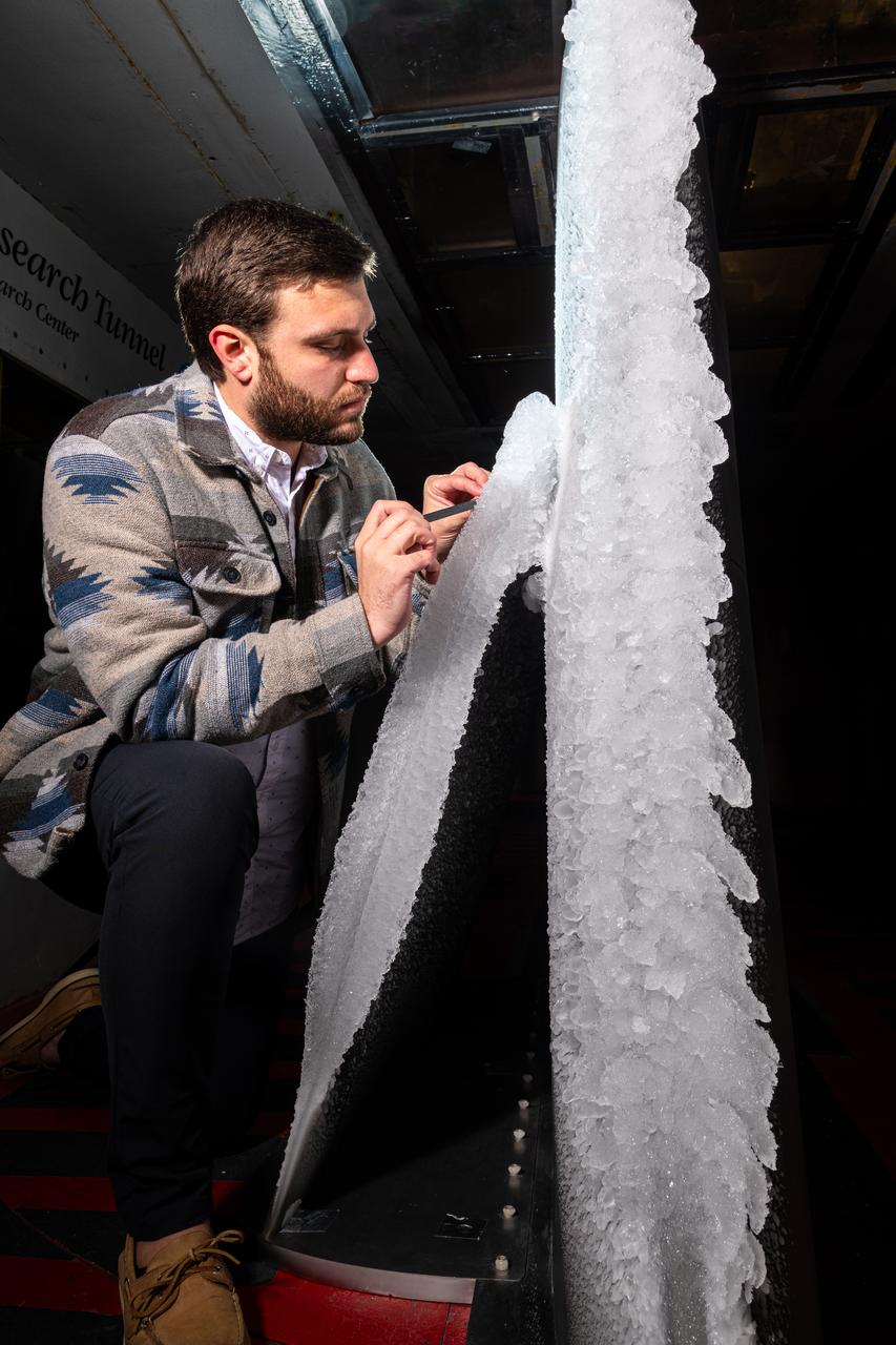
Thomas Ozoroski, an Icing Researcher, is shown documenting ice accretion on the leading edge of the next-generation Transonic Truss-Braced Wing design at NASA Glenn's Icing Research Center. This critical research will help understand icing effects for future, high-lift, ultra-efficient aircraft. Photo Credit: (NASA/Jordan Salkin)
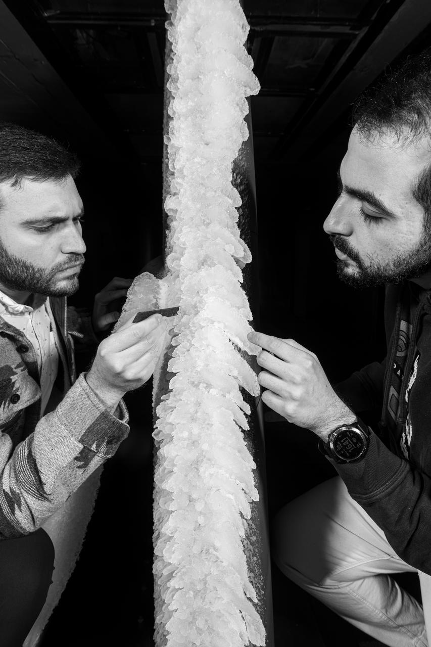
Zaid Sabri and Thomas Ozoroski, Icing Researchers, are shown documenting ice accretion on the leading edge of the next-generation Transonic Truss-Braced Wing design at NASA Glenn's Icing Research Center. This critical research will help understand icing effects for future, high-lift, ultra-efficient aircraft. Photo Credit: (NASA/Jordan Salkin)
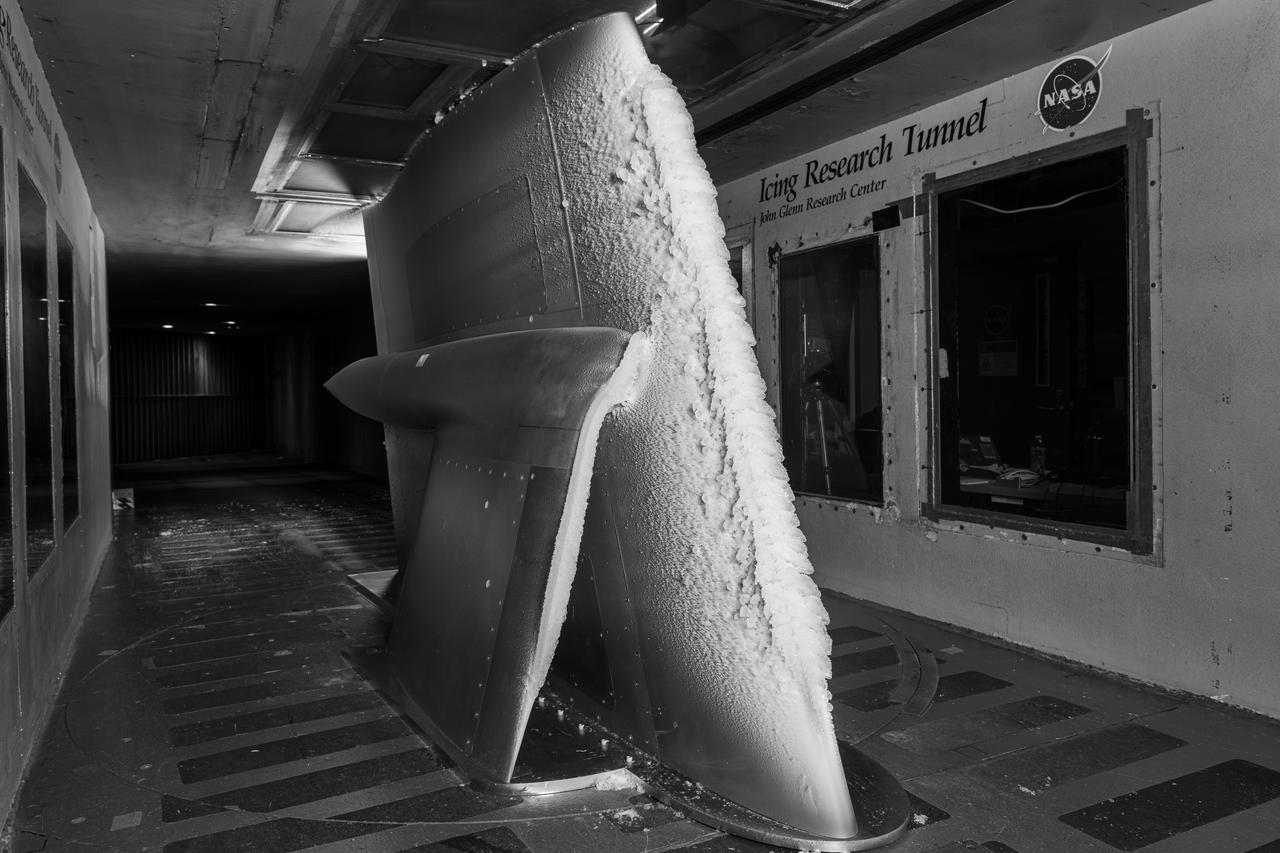
Ice accretion is shown on the leading edge of the next-generation Transonic Truss-Braced Wing design at NASA Glenn's Icing Research Center. This critical research will help understand icing effects for future, high-lift, ultra-efficient aircraft. Photo Credit: (NASA/Jordan Salkin)

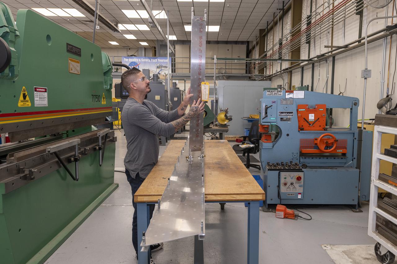
Matthew Sanchez attaches the strut and the wing to ensure they fit together as intended for a 10-foot model of the Transonic Truss-Braced Wing at NASA’s Armstrong Flight Research Center, in Edwards, California. The aircraft concept involves a wing braced on an aircraft using diagonal struts that also add lift and could result in significantly improved aerodynamics.
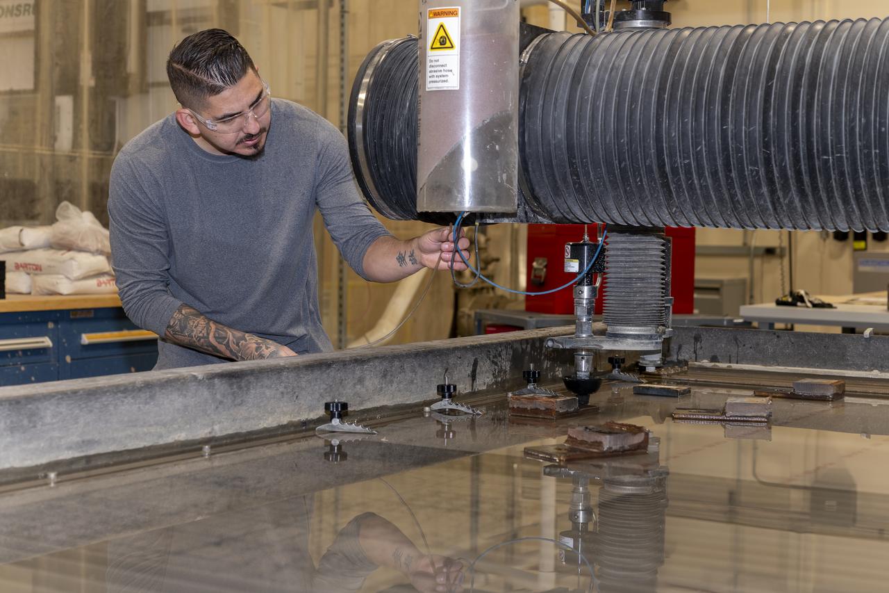
Matthew Sanchez uses a water jet to cut aluminum for the outer layer of the strut for the 10-foot model of the Transonic Truss-Braced Wing at NASA’s Armstrong Flight Research Center, in Edwards, California. The aircraft concept involves a wing braced on an aircraft using diagonal struts that also add lift and could result in significantly improved aerodynamics.

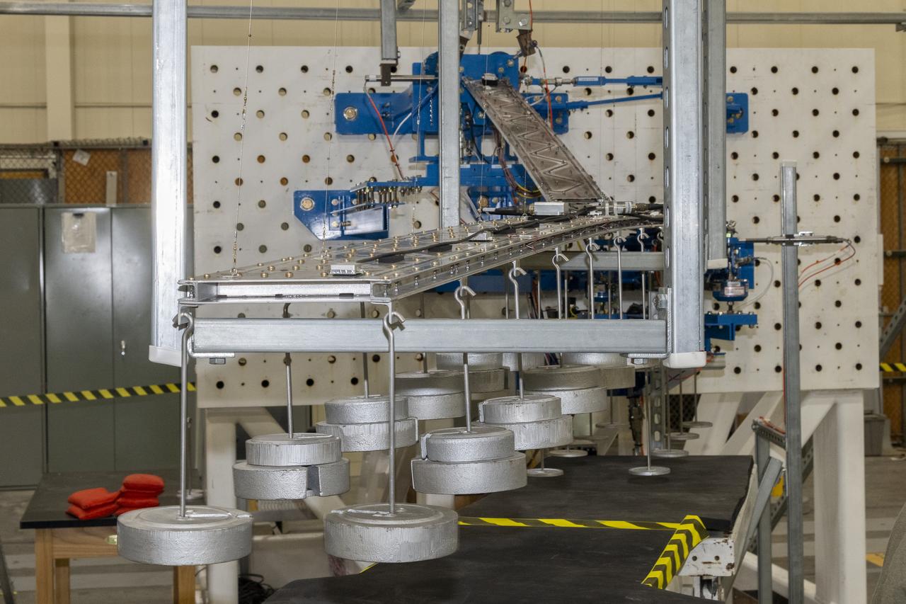
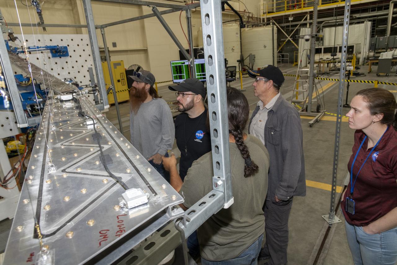
Researchers test a 10-foot Mock Truss-Braced Wing at NASA’s Armstrong Flight Research Center in Edwards, California. From left, test director Frank Pena and Ray Sadler watch as Lucas Oramas, left, and Charlie Eloff add weight to the test wing to apply stress used to determine its limits. The aircraft concept involves a wing braced on an aircraft using diagonal struts that also add lift and could result in significantly improved aerodynamics.
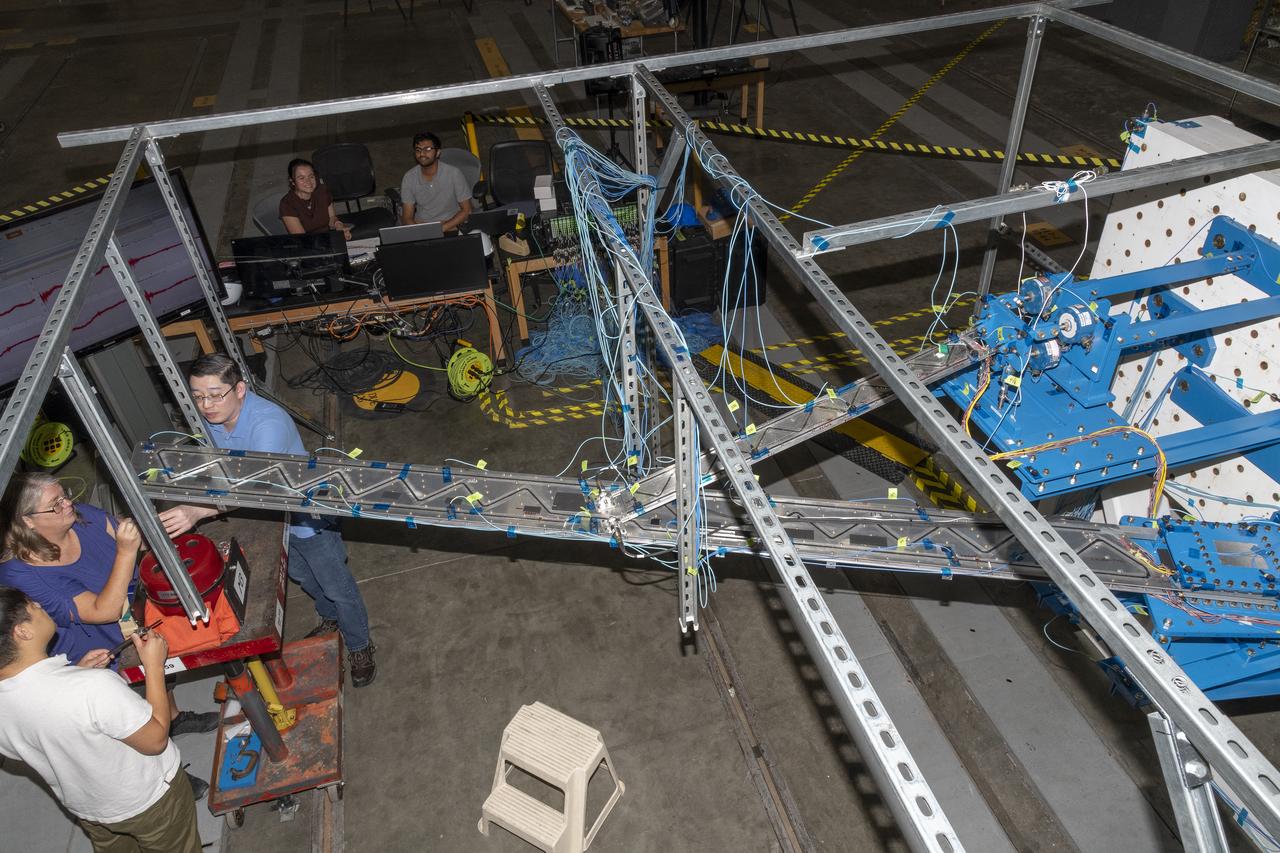
Researchers test a 10-foot Mock Truss-Braced Wing at NASA’s Armstrong Flight Research Center in Edwards, California. A view from above shows the test structure, the wing, and the strut. The aircraft concept involves a wing braced on an aircraft using diagonal struts that also add lift and could result in significantly improved aerodynamics.

Researchers test a 10-foot Mock Truss-Braced Wing at NASA’s Armstrong Flight Research Center in Edwards, California. Jonathan Lopez, from left, and Jeff Howell watch test data as it is collected. The aircraft concept involves a wing braced on an aircraft using diagonal struts that also add lift and could result in significantly improved aerodynamics.
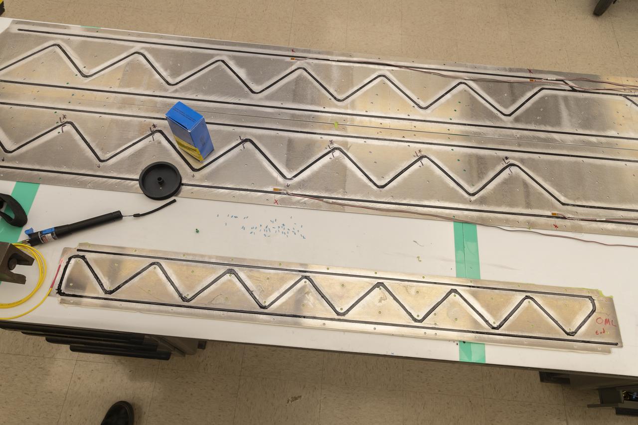
Instrumentation of the wing and strut that comprise the Mock Truss-Braced Wing 10-foot model are complete at NASA’s Armstrong Flight Research Center in Edwards, California.
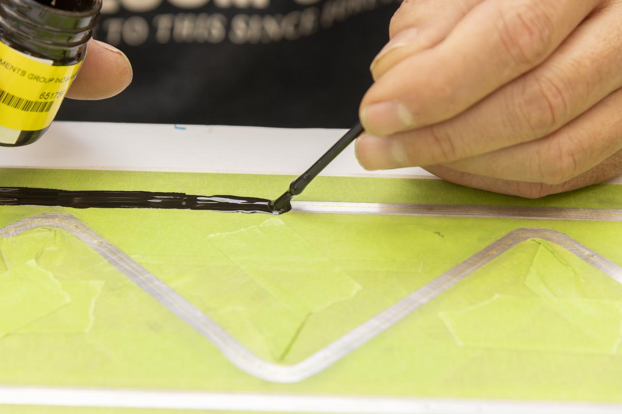
An epoxy is applied to adhere the fiber optic sensor installation on the Mock Truss-Braced Wing 10-foot model at NASA’s Armstrong Flight Research Center in Edwards, California.
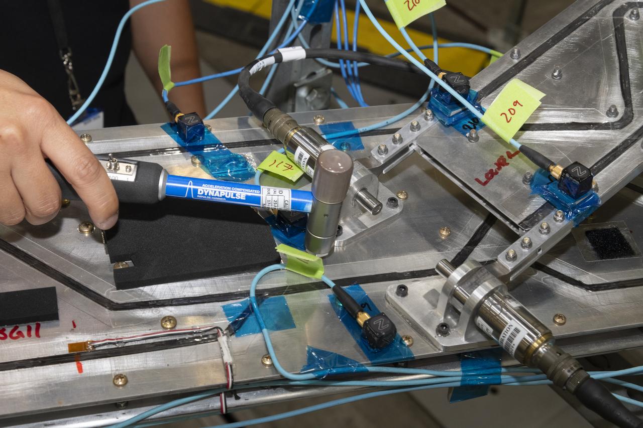
Researchers test a 10-foot Mock Truss-Braced Wing at NASA’s Armstrong Flight Research Center in Edwards, California. Ben Park, NASA mock wing ground vibration test director, taps the wing structure with an instrumented hammer in key locations and sensors monitor the results. The aircraft concept involves a wing braced on an aircraft using diagonal struts that also add lift and could result in significantly improved aerodynamics.

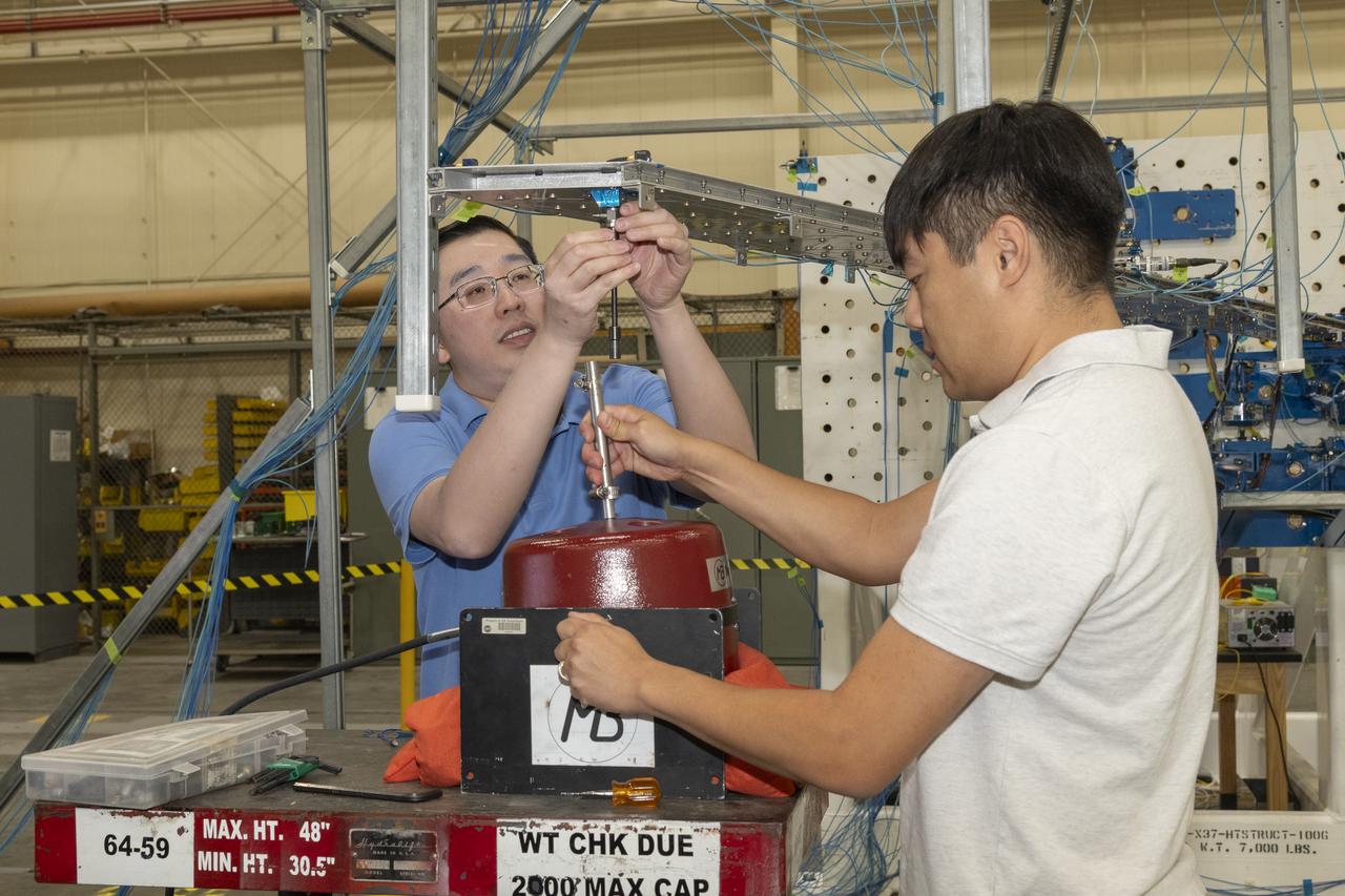
Aaron Rumsey and Beto Hinojos carefully add weight to a 6-foot model of the Transonic Truss-Braced Wing at NASA’s Armstrong Flight Research Center, in Edwards, California. The aircraft concept involves a wing braced on an aircraft using diagonal struts that also add lift and could result in significantly improved aerodynamics.

Engineering technician Jeff Howell mounts conventional strain gauges to the Mock Truss-Braced Wing 10-foot model at NASA’s Armstrong Flight Research Center in Edwards, California. The conventional system data will be compared the Fiber Optic Sensing System developed at the center on the same wing to see how well the testing methods match.
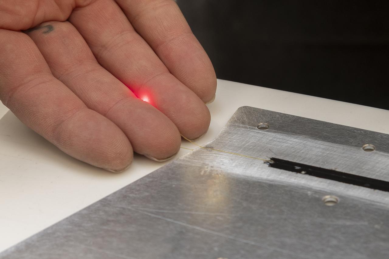
A red light confirms that the fiber of the Fiber Optic Sensing System installed on the Mock Truss-Braced Wing 10-foot model works as intended at NASA’s Armstrong Flight Research Center in Edwards, California. The fiber, which is about the thickness of a human hair, is part of a system that can provide strain information researchers can use to determine the model’s durability.
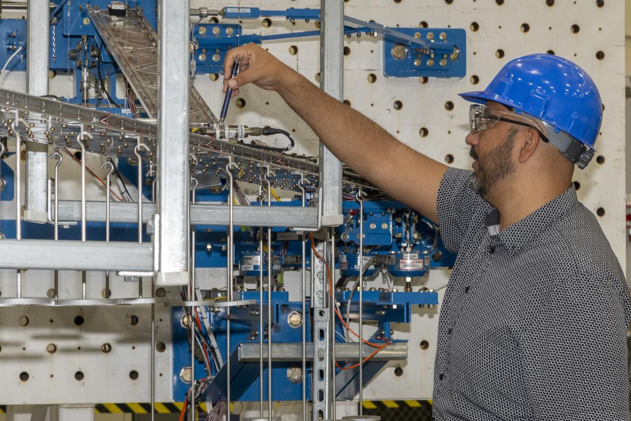
Researchers test a 10-foot Mock Truss-Braced Wing at NASA’s Armstrong Flight Research Center in Edwards, California. Frank Pena, test director, checks the mock wing. The aircraft concept involves a wing braced on an aircraft using diagonal struts that also add lift and could result in significantly improved aerodynamics.
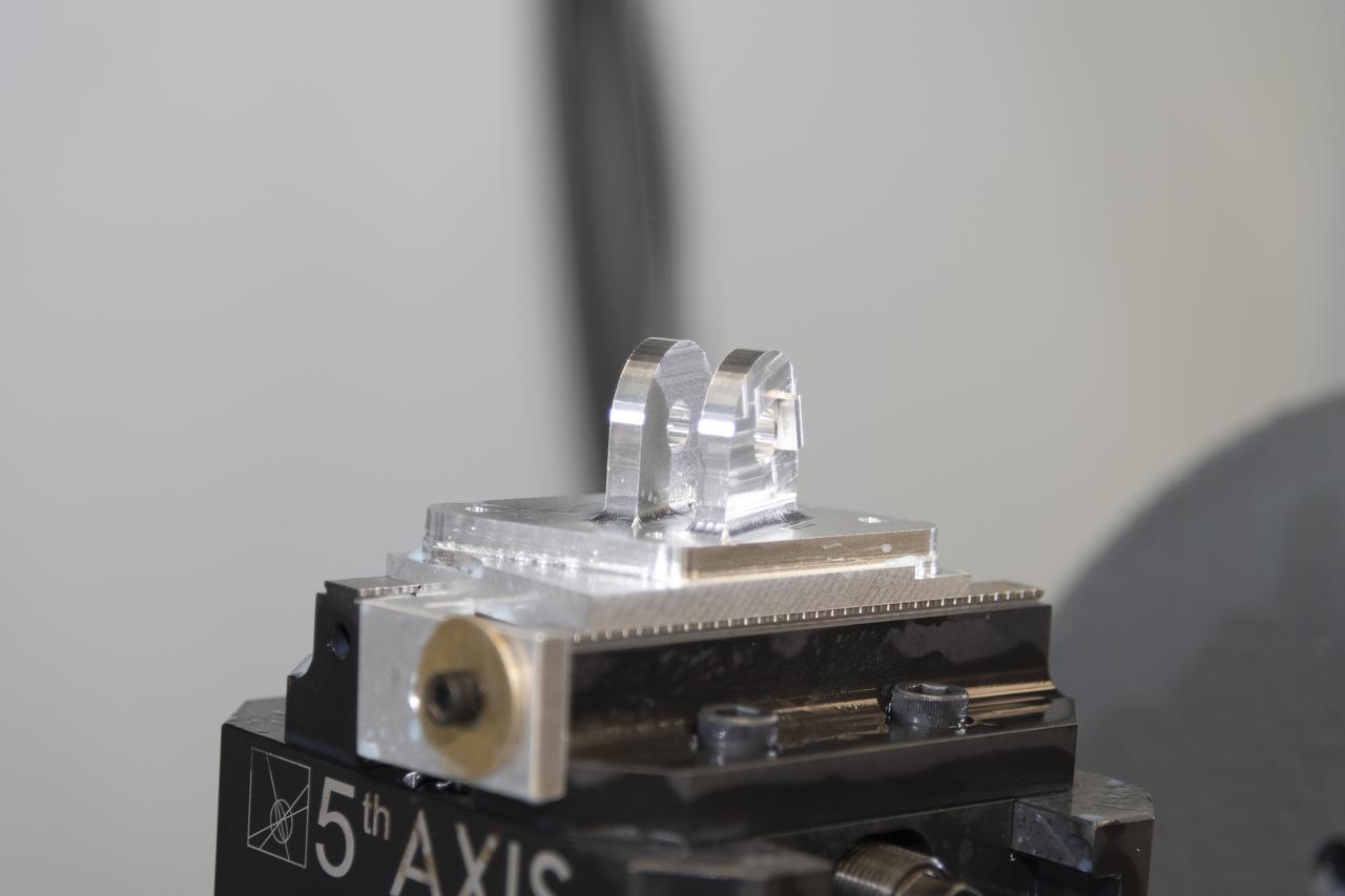
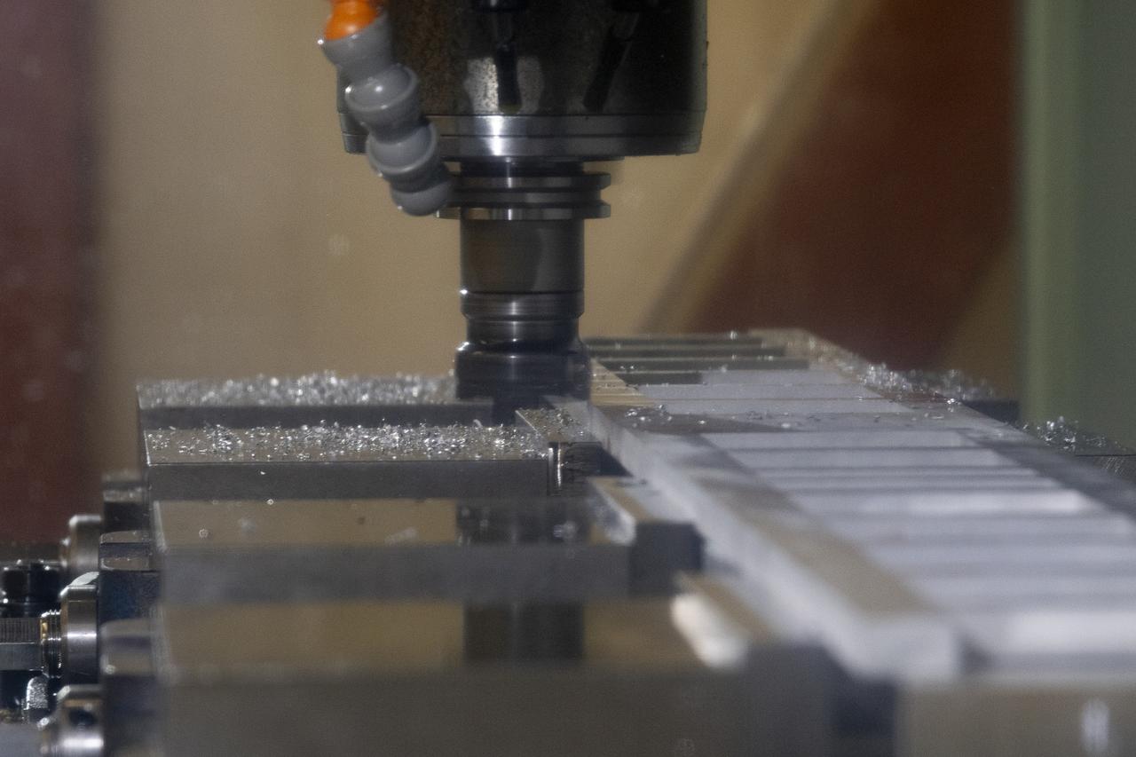
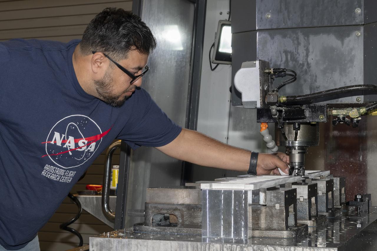
A block of aluminum is transformed by a machine programmed to cut, rotate, and turn it to make a forward wing strut fastener for a 10-foot model of the Transonic Truss-Braced Wing at NASA’s Armstrong Flight Research Center, in Edwards, California. The aircraft concept involves a wing braced on an aircraft using diagonal struts that also add lift and could result in significantly improved aerodynamics.
Frank Pena and Benjamin Park watch as data streams in from tests on a 6-foot model of the Transonic Truss-Braced Wing at NASA’s Armstrong Flight Research Center, in Edwards, California.

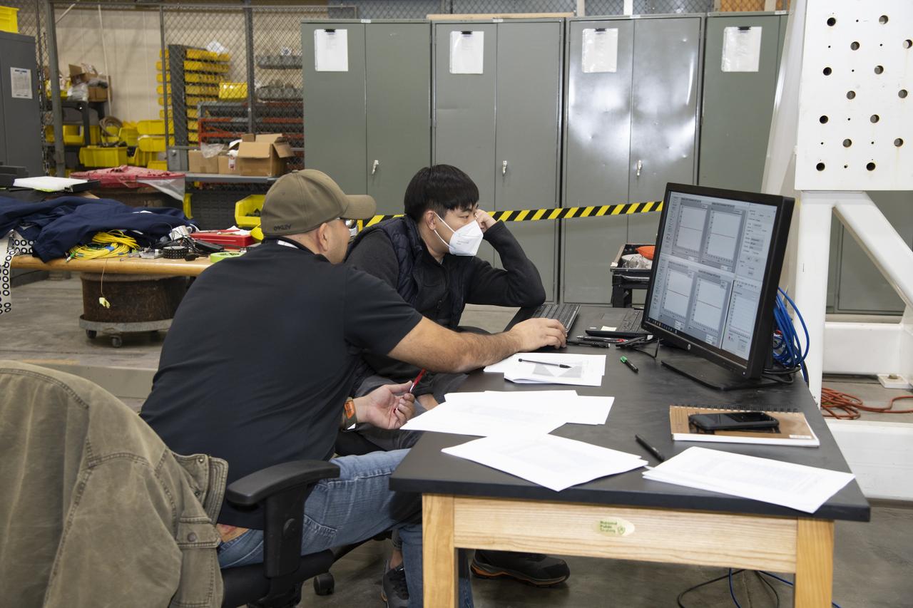
Jose Vasquez programed a machine to cut, rotate and turn a block of steel to form a jury strut adaptor for a 10-foot model of the Transonic Truss-Braced Wing at NASA’s Armstrong Flight Research Center, in Edwards, California. The aircraft concept involves a wing braced on an aircraft using diagonal struts that also add lift and could result in significantly improved aerodynamics.
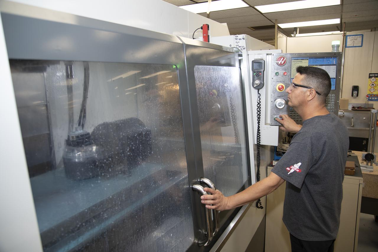
Jose Vasquez uses a machine to cut, rotate and turn a block of aluminum to make a forward wing strut fastener for a 10-foot model of the Transonic Truss-Braced Wing at NASA’s Armstrong Flight Research Center, in Edwards, California. The aircraft concept involves a wing braced on an aircraft using diagonal struts that also add lift and could result in significantly improved aerodynamics.
A jury strut adaptor is created for a 10-foot model of the Transonic Truss-Braced Wing at NASA’s Armstrong Flight Research Center, in Edwards, California. The aircraft concept involves a wing braced on an aircraft using diagonal struts that also add lift and could result in significantly improved aerodynamics.
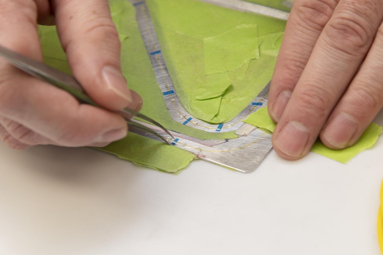
Engineering technician Jeff Howell removes thin pieces of tape from fiber used for a bonding process on the Mock Truss-Braced Wing 10-foot model at NASA’s Armstrong Flight Research Center in Edwards, California.
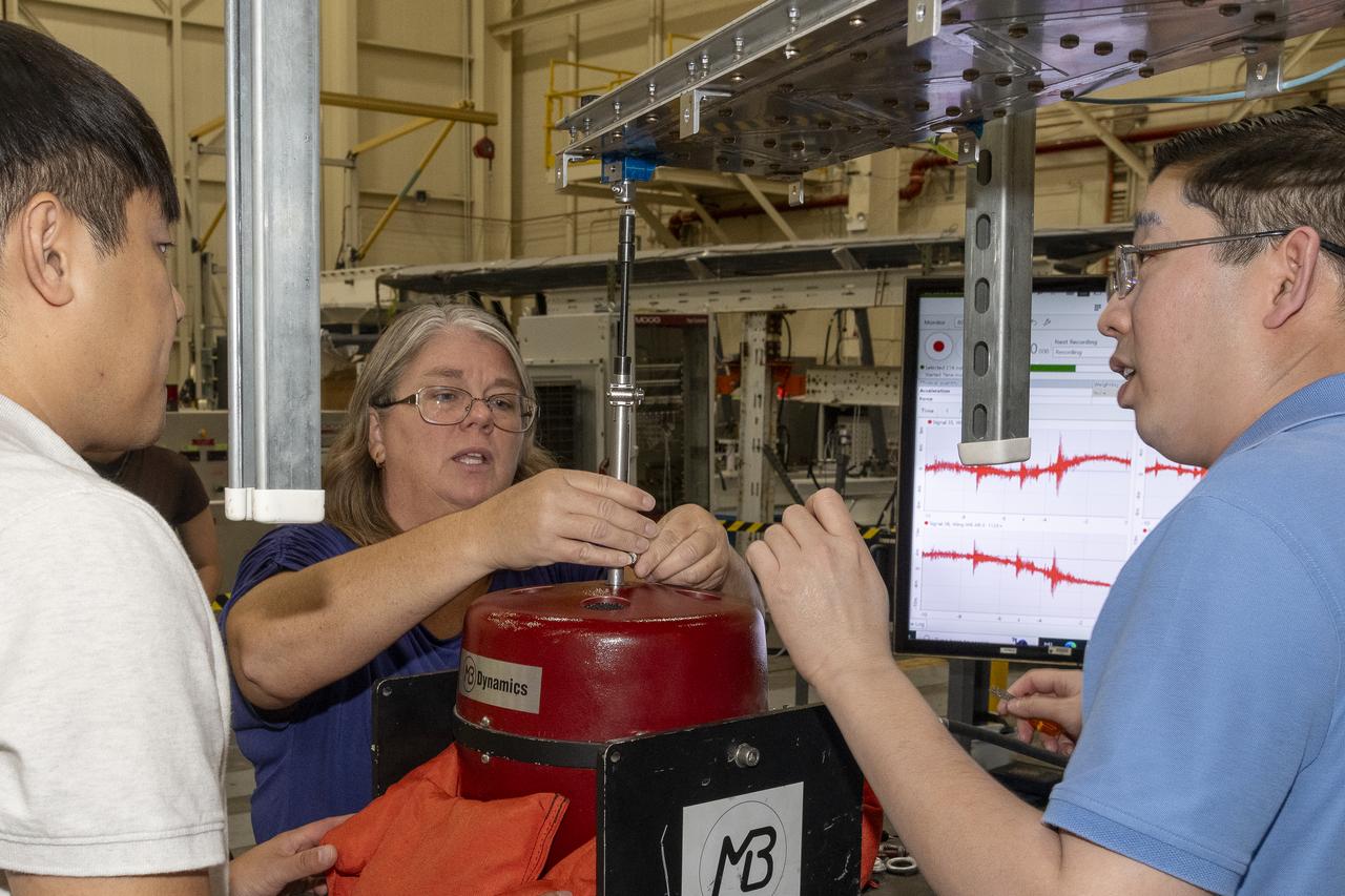
Researchers test a 10-foot Mock Truss-Braced Wing at NASA’s Armstrong Flight Research Center in Edwards, California. From left, ground vibration test director Ben Park, Natalie Spivey, and Samson Truong, prepare for a vibration test. The aircraft concept involves a wing braced on an aircraft using diagonal struts that also add lift and could result in significantly improved aerodynamics.
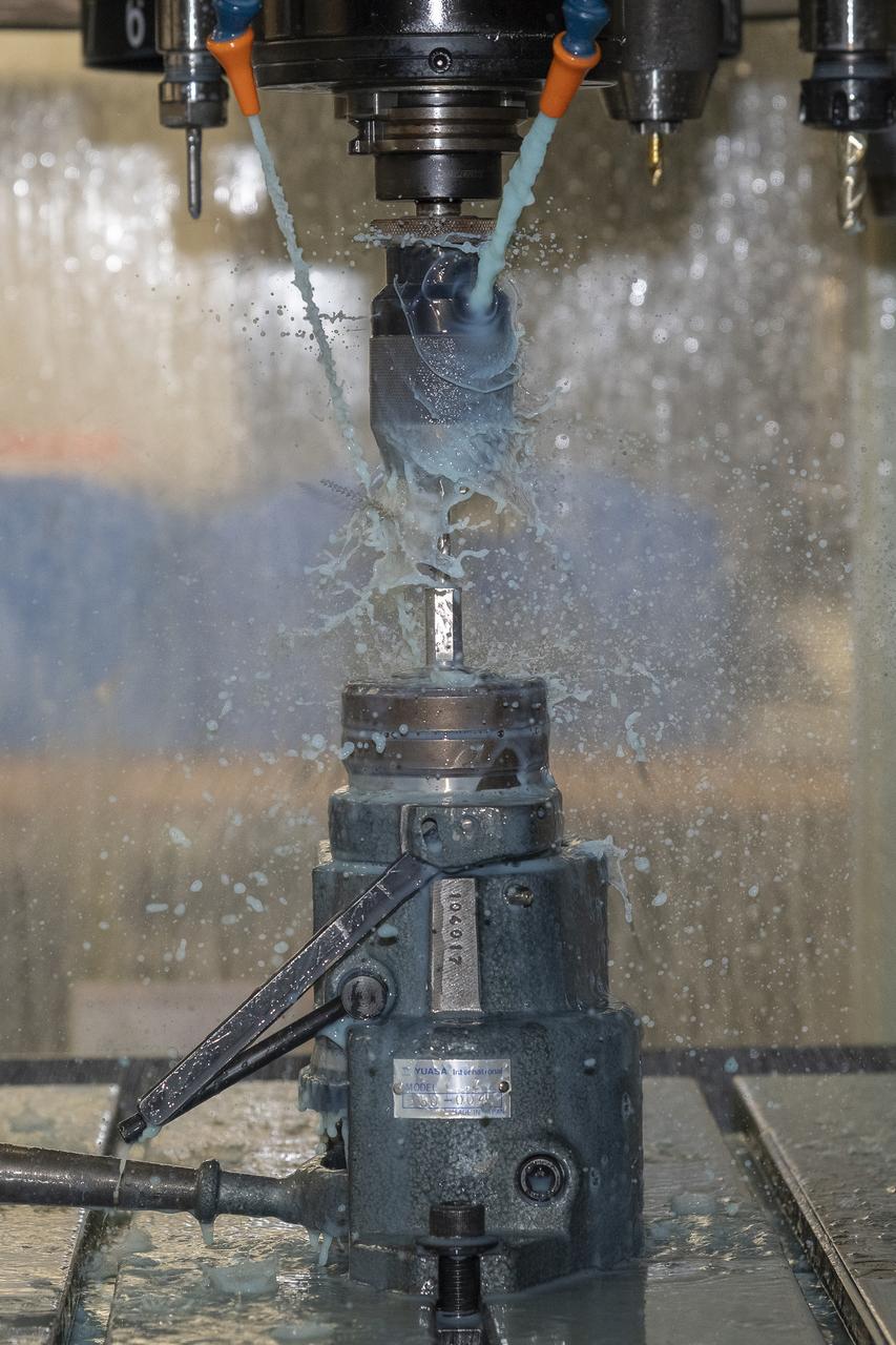
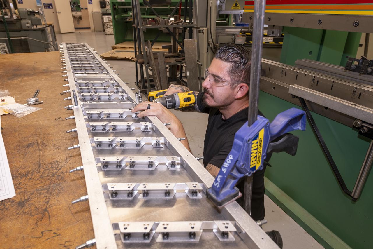
A milling machine drills holes in the strut frame assembly for a 10-foot model of the Transonic Truss-Braced Wing at NASA’s Armstrong Flight Research Center, in Edwards, California. The aircraft concept involves a wing braced on an aircraft using diagonal struts that also add lift and could result in significantly improved aerodynamics.
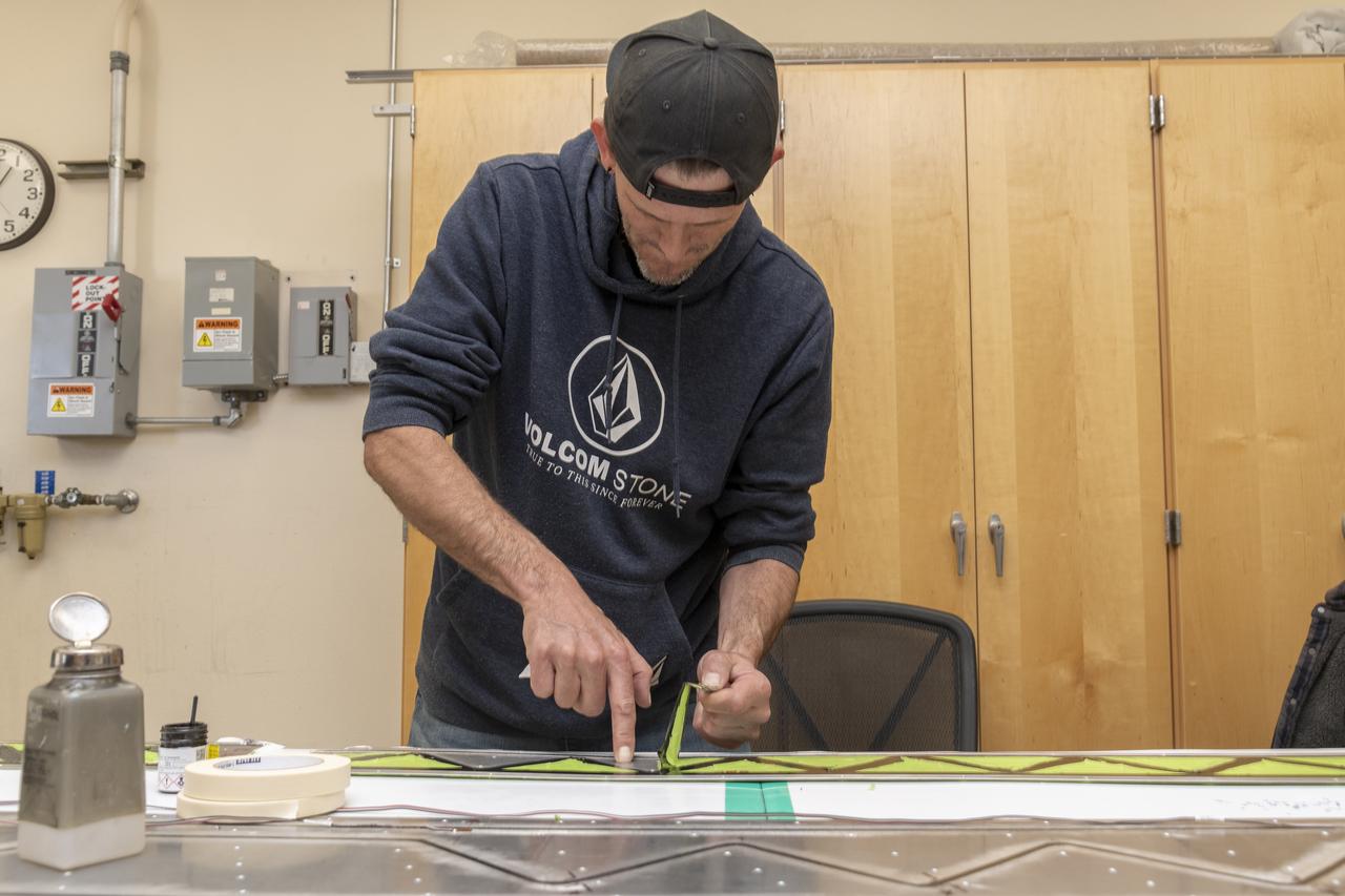
Engineering technician Jeff Howell removes tape from the Mock Truss-Braced Wing 10-foot model at NASA’s Armstrong Flight Research Center in Edwards, California. The tape was used to limit the amount of epoxy on the model wing during the process to secure the fiber optic strain sensors to the wing.
Researchers test a 10-foot Mock Truss-Braced Wing at NASA’s Armstrong Flight Research Center in Edwards, California. The aircraft concept involves a wing braced on an aircraft using diagonal struts that also add lift and could result in significantly improved aerodynamics.
Matthew Sanchez places the strut and the wing side-by-side before assembling them for a check to ensure they fit together as intended for a 10-foot model of the Transonic Truss-Braced Wing at NASA’s Armstrong Flight Research Center, in Edwards, California. The aircraft concept involves a wing braced on an aircraft using diagonal struts that also add lift and could result in significantly improved aerodynamics.
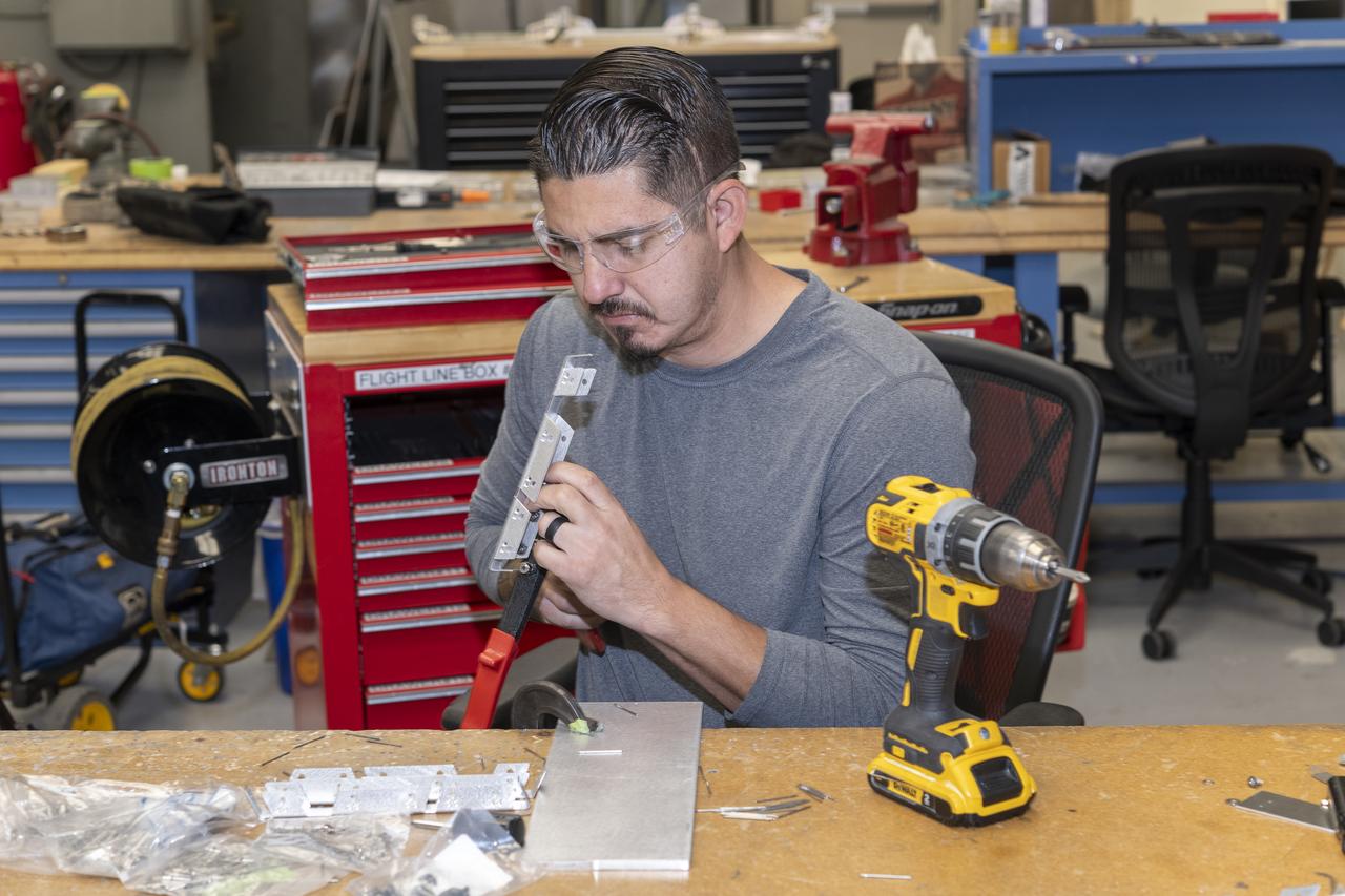
Matthew Sanchez assembles wing ribs for a 10-foot model of the Transonic Truss-Braced Wing at NASA’s Armstrong Flight Research Center, in Edwards, California. The aircraft concept involves a wing braced on an aircraft using diagonal struts that also add lift and could result in significantly improved aerodynamics.
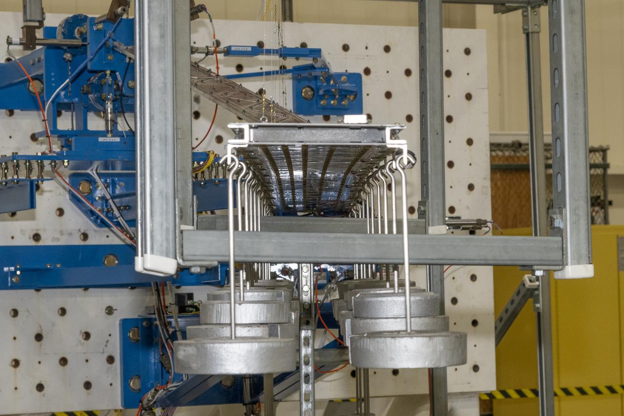
Researchers test a 10-foot Mock Truss-Braced Wing at NASA’s Armstrong Flight Research Center in Edwards, California. Weights are hung from the wing to apply stress used to determine its limits. The aircraft concept involves a wing braced on an aircraft using diagonal struts that also add lift and could result in significantly improved aerodynamics.
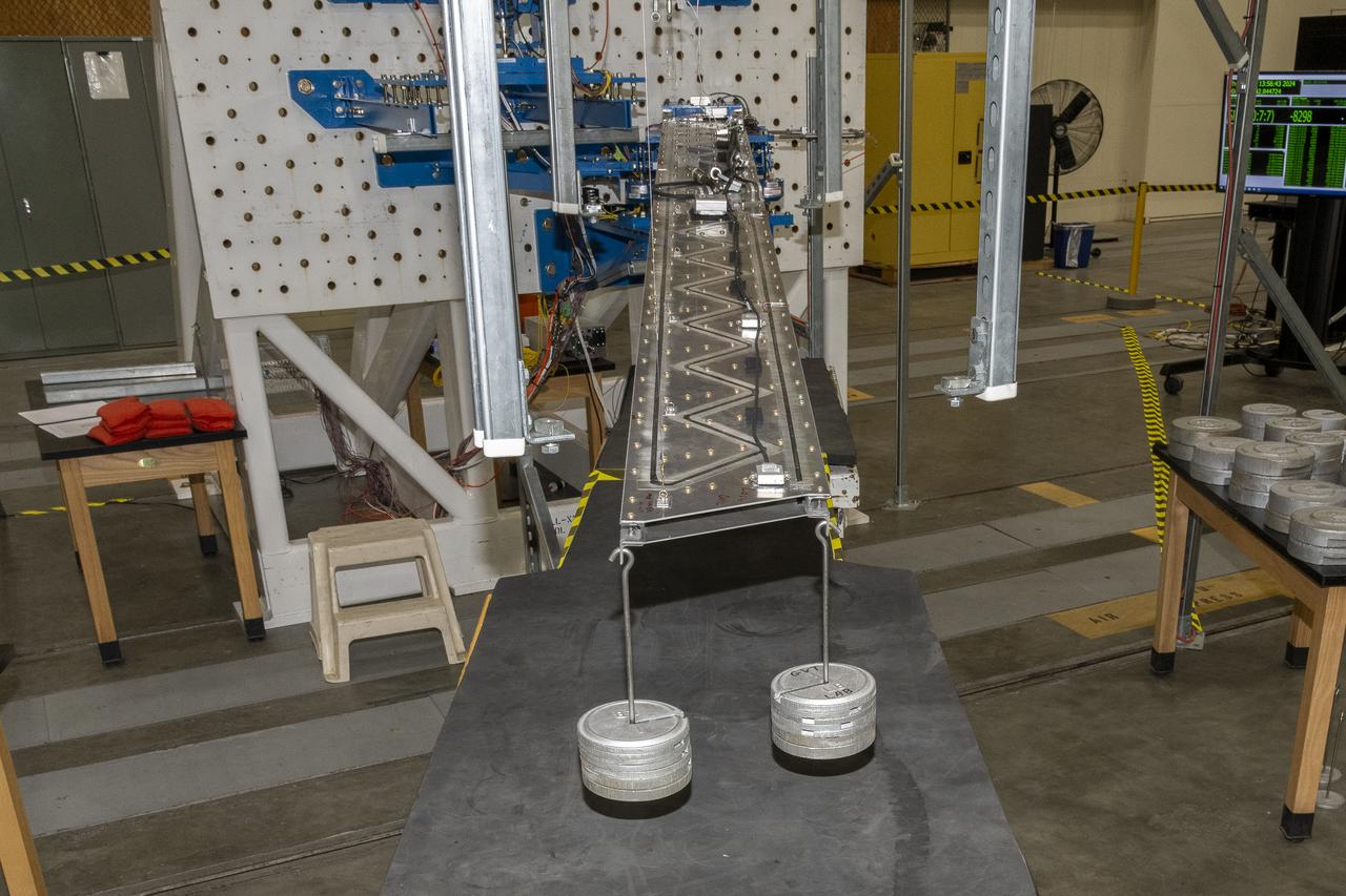
Researchers test a 10-foot Mock Truss-Braced Wing at NASA’s Armstrong Flight Research Center in Edwards, California. Weights are added to the wingtip to apply stress used to determine its limits. The aircraft concept involves a wing braced on an aircraft using diagonal struts that also add lift and could result in significantly improved aerodynamics.
Matthew Sanchez assembles wing ribs to the 10-foot model of the Transonic Truss-Braced Wing at NASA’s Armstrong Flight Research Center, in Edwards, California. The aircraft concept involves a wing braced on an aircraft using diagonal struts that also add lift and could result in significantly improved aerodynamics.
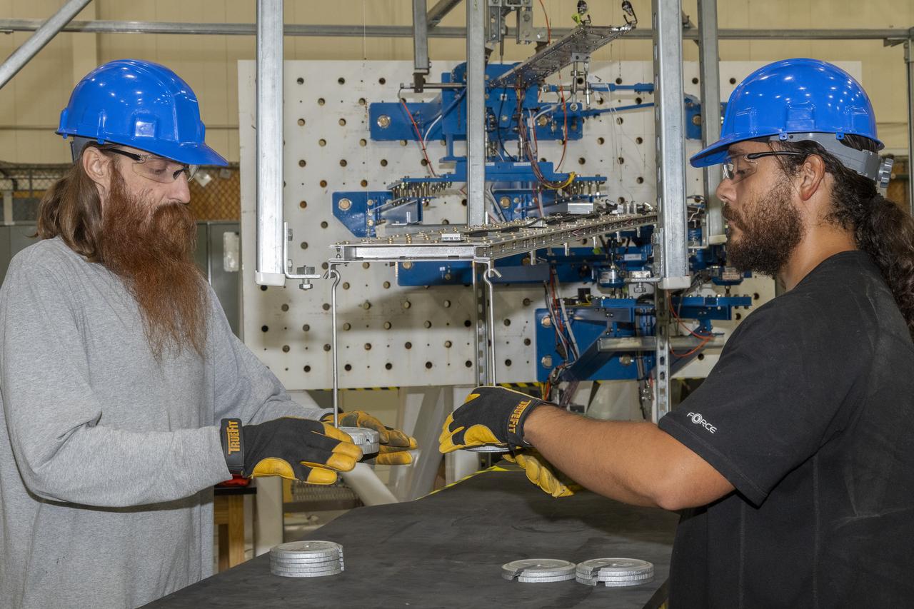
Researchers test a 10-foot Mock Truss-Braced Wing at NASA’s Armstrong Flight Research Center in Edwards, California. Charlie Eloff, left, and Lucas Oramas add weight to the test wing to apply stress used to determine its limits. The aircraft concept involves a wing braced on an aircraft using diagonal struts that also add lift and could result in significantly improved aerodynamics.
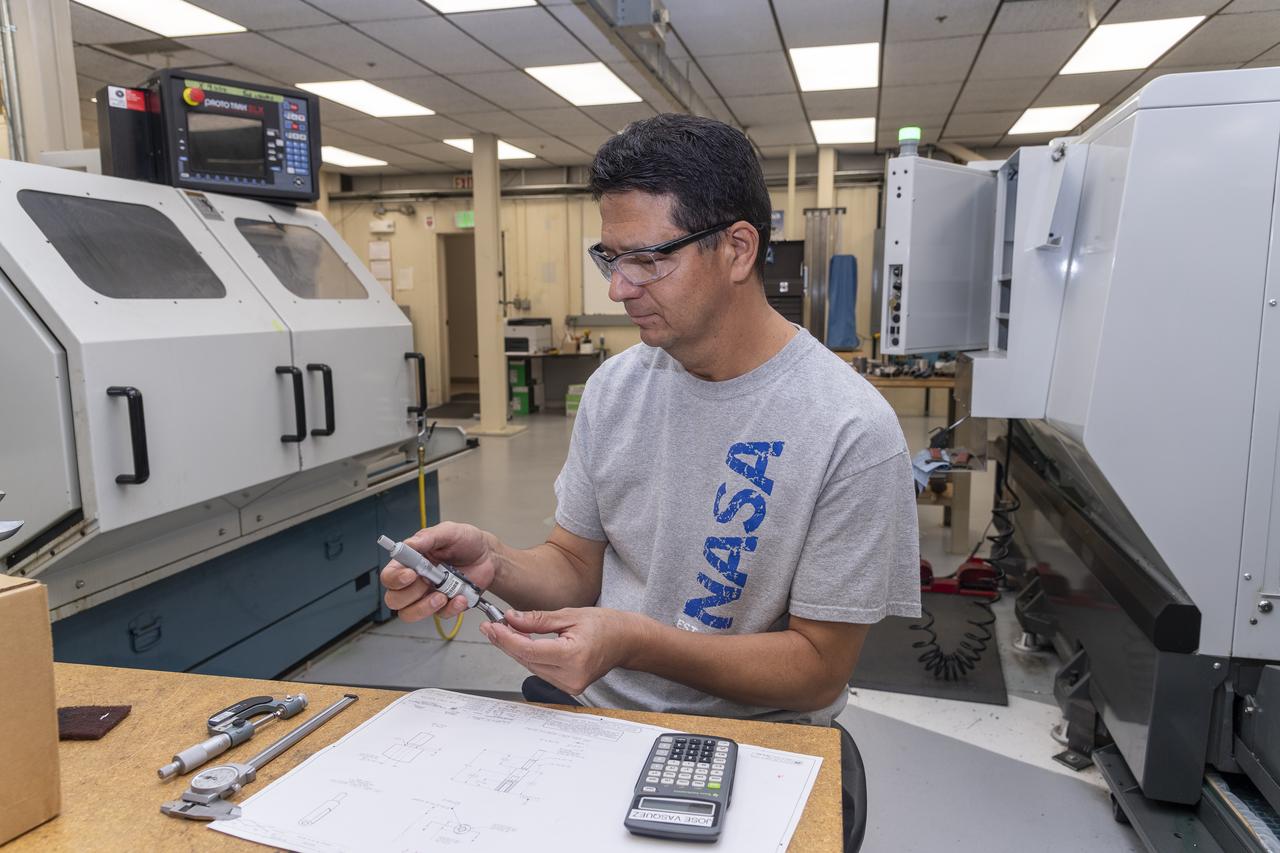
Jose Vasquez verifies a jury strut adaptor created for a 10-foot model of the Transonic Truss-Braced Wing at NASA’s Armstrong Flight Research Center, in Edwards, California. The aircraft concept involves a wing braced on an aircraft using diagonal struts that also add lift and could result in significantly improved aerodynamics.
Researchers test a 10-foot Mock Truss-Braced Wing at NASA’s Armstrong Flight Research Center in Edwards, California. The test team makes observations between tests. The aircraft concept involves a wing braced on an aircraft using diagonal struts that also add lift and could result in significantly improved aerodynamics.
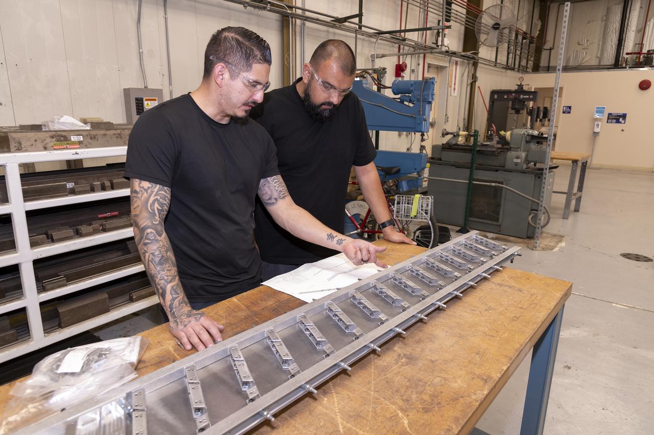
Matthew Sanchez, left, consults with Sal Navarro on assembling wing ribs to the 10-foot model of the Transonic Truss-Braced Wing at NASA’s Armstrong Flight Research Center, in Edwards, California. The aircraft concept involves a wing braced on an aircraft using diagonal struts that also add lift and could result in significantly improved aerodynamics.
Matthew Sanchez attaches the strut and the wing to ensure they fit together as intended for a 10-foot model of the Transonic Truss-Braced Wing at NASA’s Armstrong Flight Research Center, in Edwards, California. The aircraft concept involves a wing braced on an aircraft using diagonal struts that also add lift and could result in significantly improved aerodynamics.
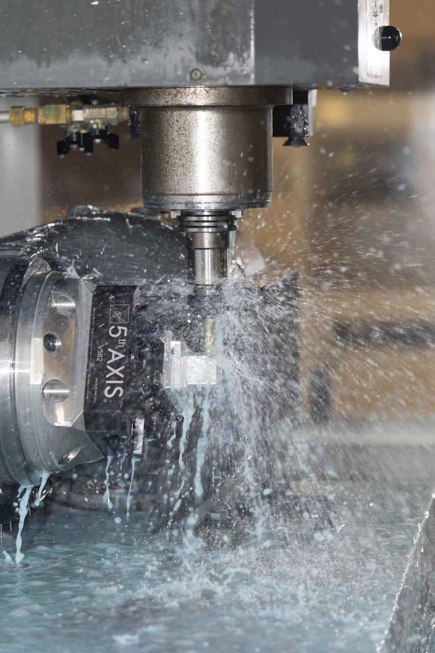
A machine cuts, rotates, and turns a block of aluminum to make a forward wing strut fastener for a 10-foot model of the Transonic Truss-Braced Wing at NASA’s Armstrong Flight Research Center, in Edwards, California. The aircraft concept involves a wing braced on an aircraft using diagonal struts that also add lift and could result in significantly improved aerodynamics.
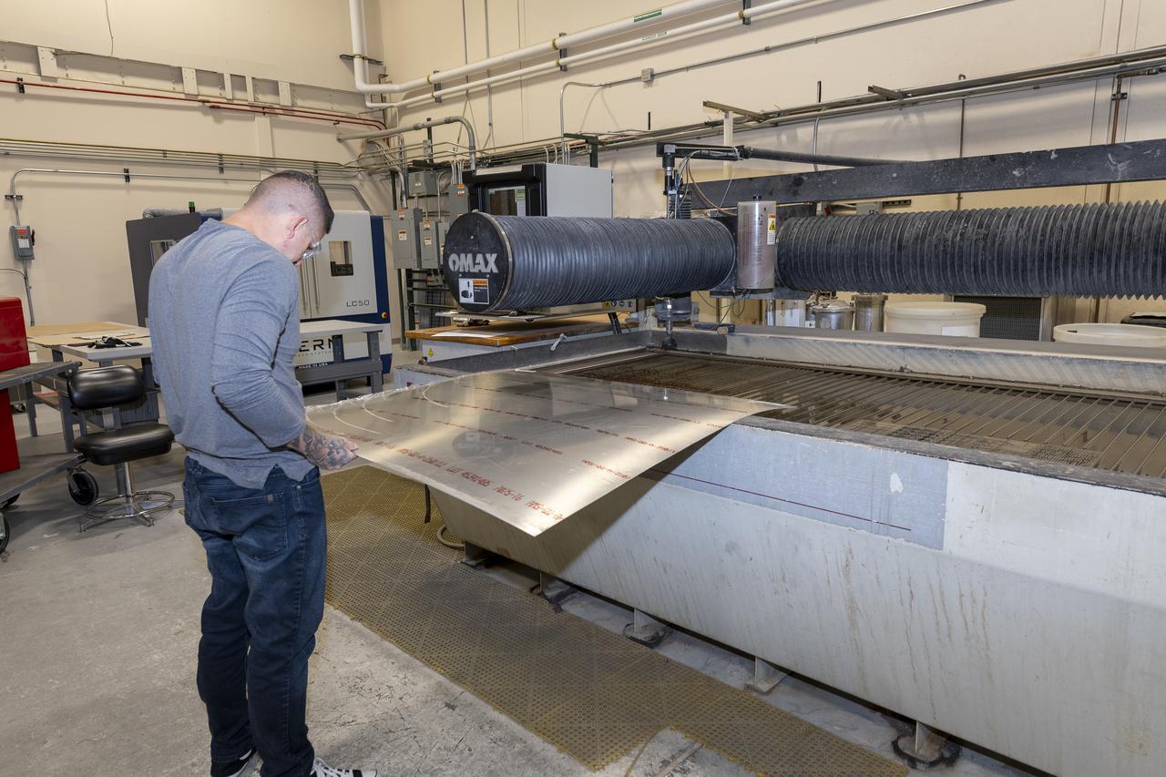
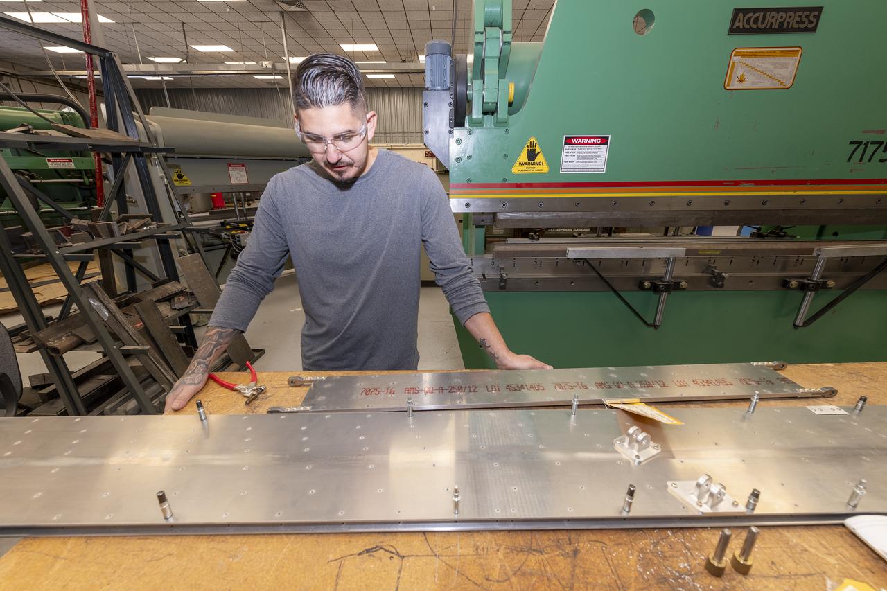
Matthew Sanchez prepares a sheet of aluminum that will be cut into the outer layer of the strut for the 10-foot model of the Transonic Truss-Braced Wing at NASA’s Armstrong Flight Research Center, in Edwards, California. The aircraft concept involves a wing braced on an aircraft using diagonal struts that also add lift and could result in significantly improved aerodynamics.
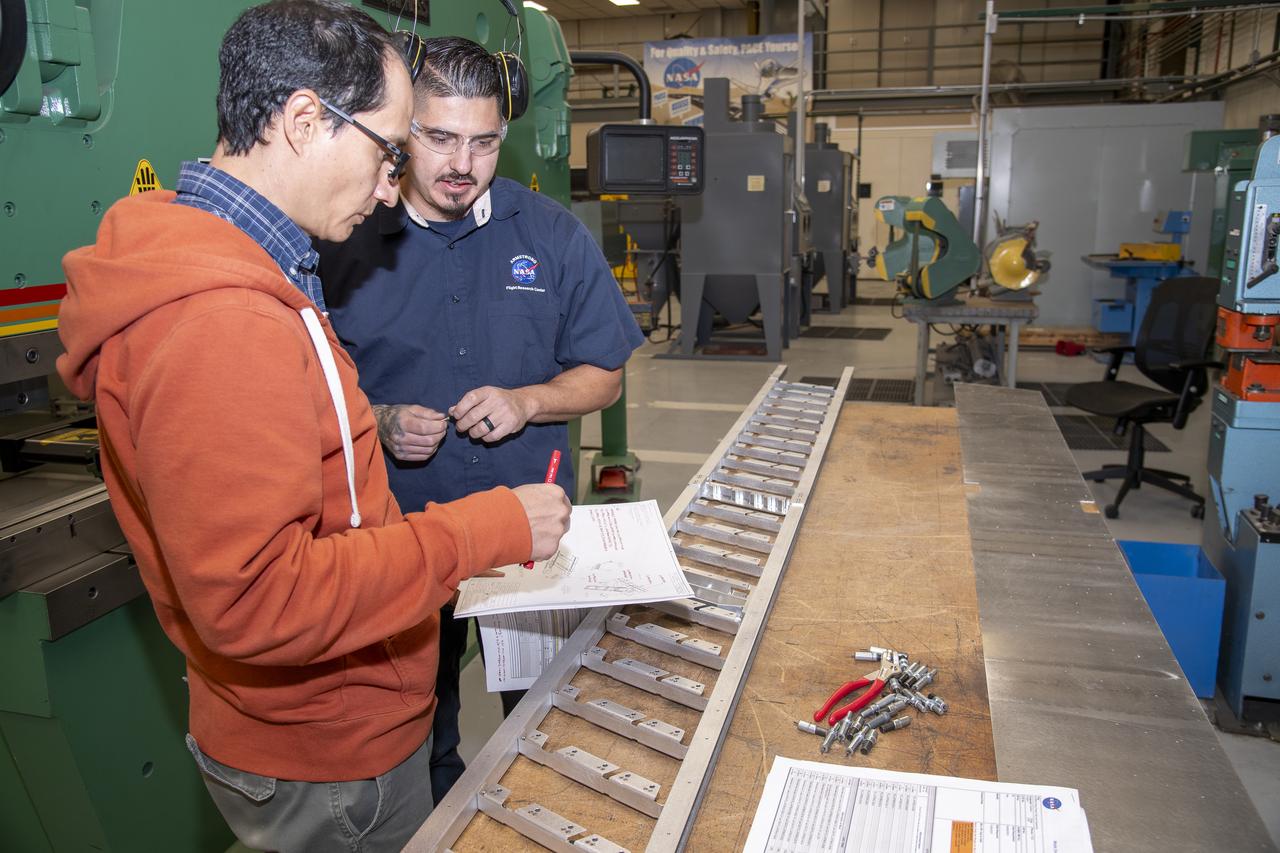
German Escobar works on milling the strut frame assembly for a 10-foot model of the Transonic Truss-Braced Wing at NASA’s Armstrong Flight Research Center, in Edwards, California. The aircraft concept involves a wing braced on an aircraft using diagonal struts that also add lift and could result in significantly improved aerodynamics.
Researchers test a 10-foot Mock Truss-Braced Wing at NASA’s Armstrong Flight Research Center in Edwards, California. Samson Truong, from left, and Ben Park, NASA mock wing ground vibration test director, prepare for a vibration test. The aircraft concept involves a wing braced on an aircraft using diagonal struts that also add lift and could result in significantly improved aerodynamics.
Matthew Sanchez consults with Andrew Holguin on the strut for a 10-foot model of the Transonic Truss-Braced Wing at NASA’s Armstrong Flight Research Center, in Edwards, California. The aircraft concept involves a wing braced on an aircraft using diagonal struts that also add lift and could result in significantly improved aerodynamics.
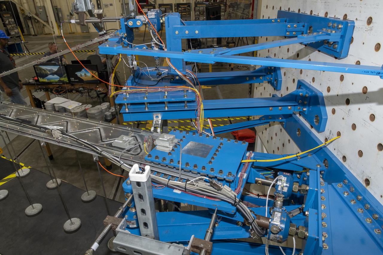
Researchers test a 10-foot Mock Truss-Braced Wing at NASA’s Armstrong Flight Research Center in Edwards, California. The infrastructure, in blue, holds the wing and truss and enables the test. The aircraft concept involves a wing braced on an aircraft using diagonal struts that also add lift and could result in significantly improved aerodynamics.