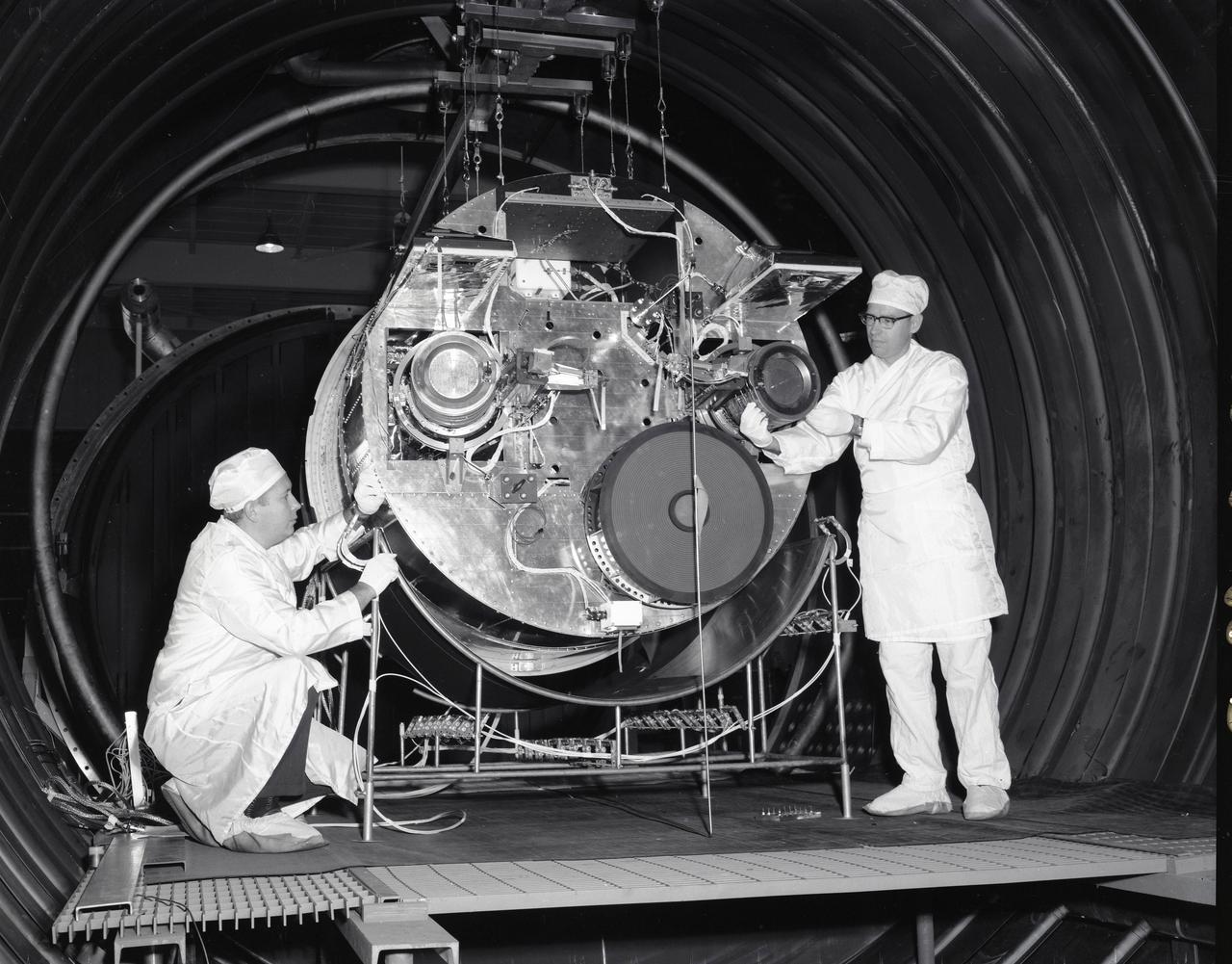
SPACE ELECTRIC ROCKET TEST, SERT II IN TANK 5
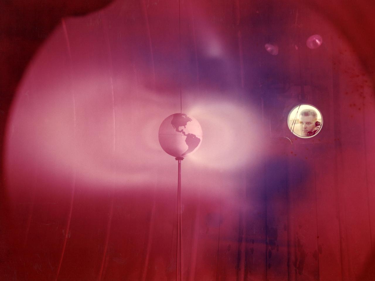
The model of the Earth housed inside Vacuum Tank 5 contained a coil which produced a magnetic field simulating that of the Earth. It was bombarded with a stream of ionized particles simulating the solar wind which impinges on the Earth's magnetic field. The bands or belts of luminous plasma seen in this image were suggestive of the Van Allen belts found around the Earth. Scientists at Lewis probed the plasma around the model and studied scaling laws in an attempt to find an explanation for the actual formation of the Van Allen belt.
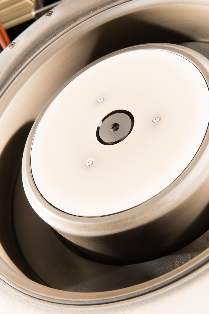
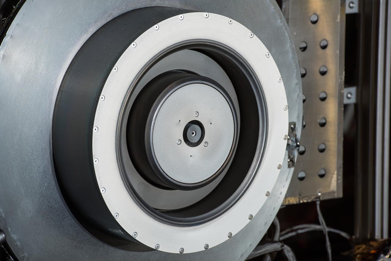
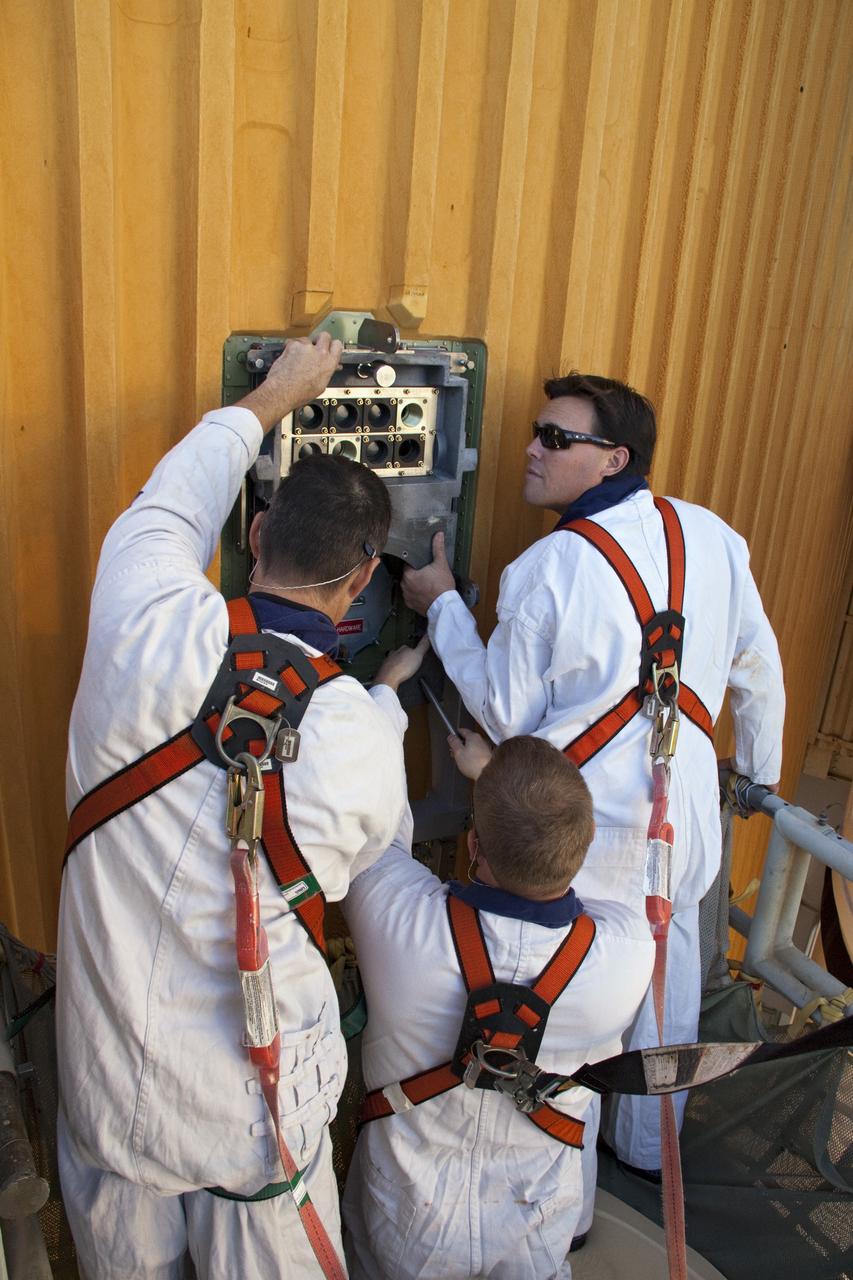
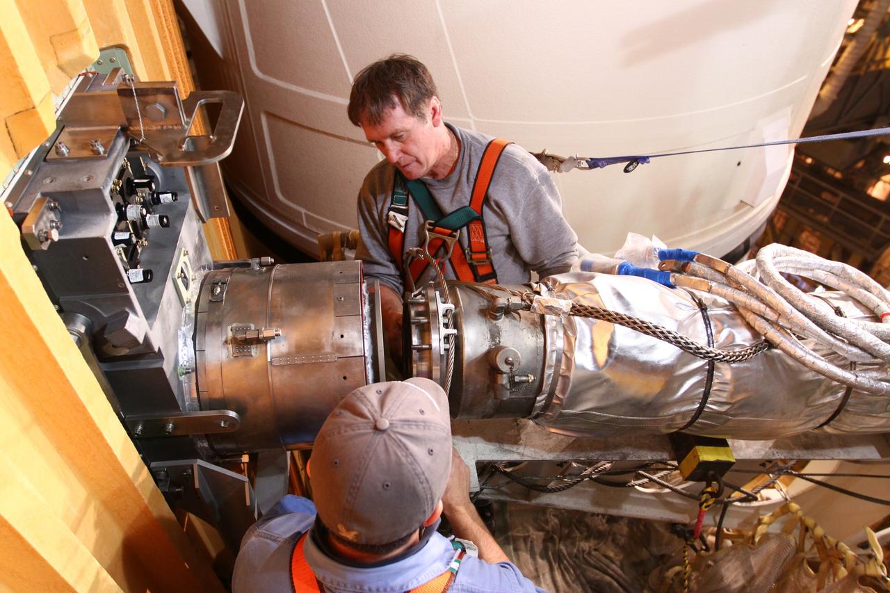
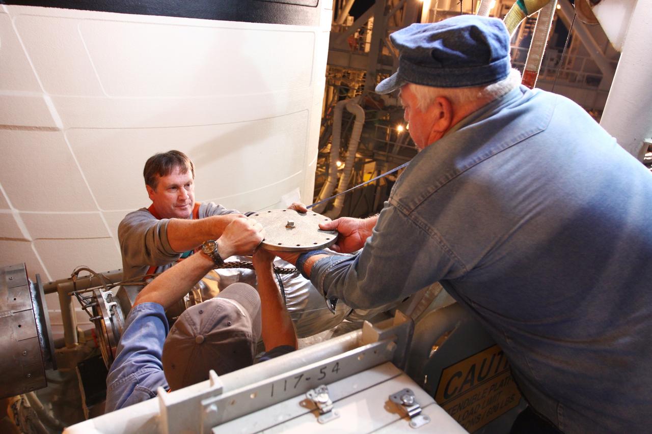
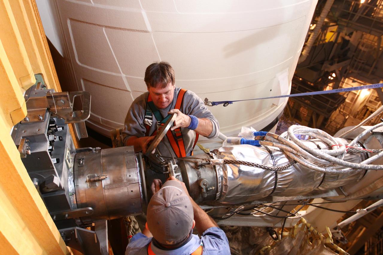
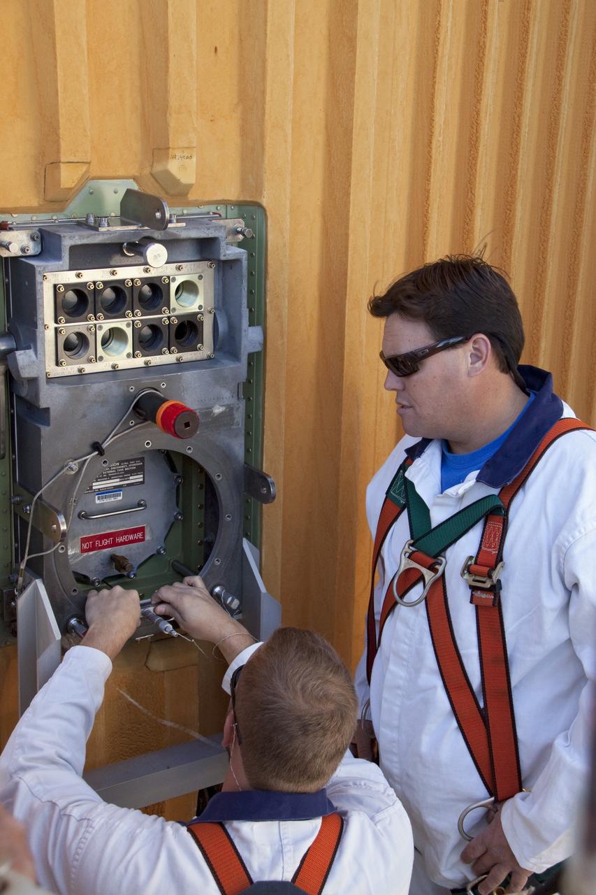
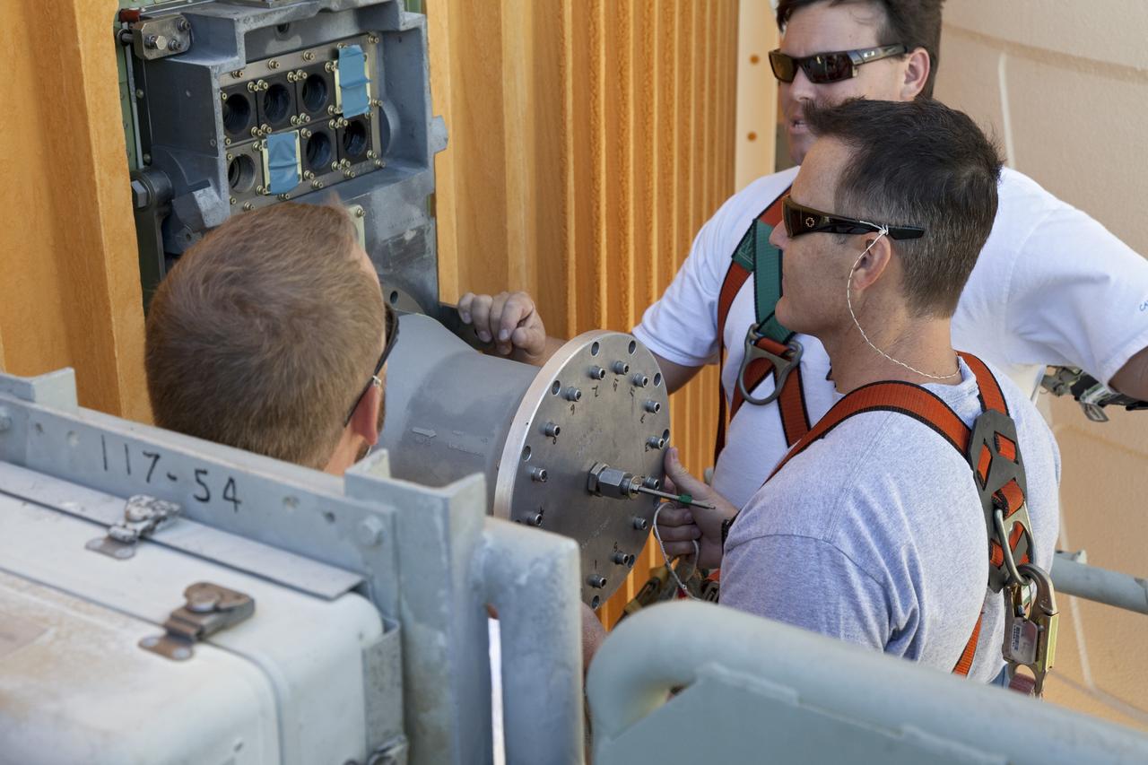
Hall Thruster in Tank 5
Hall Thruster in Tank 5
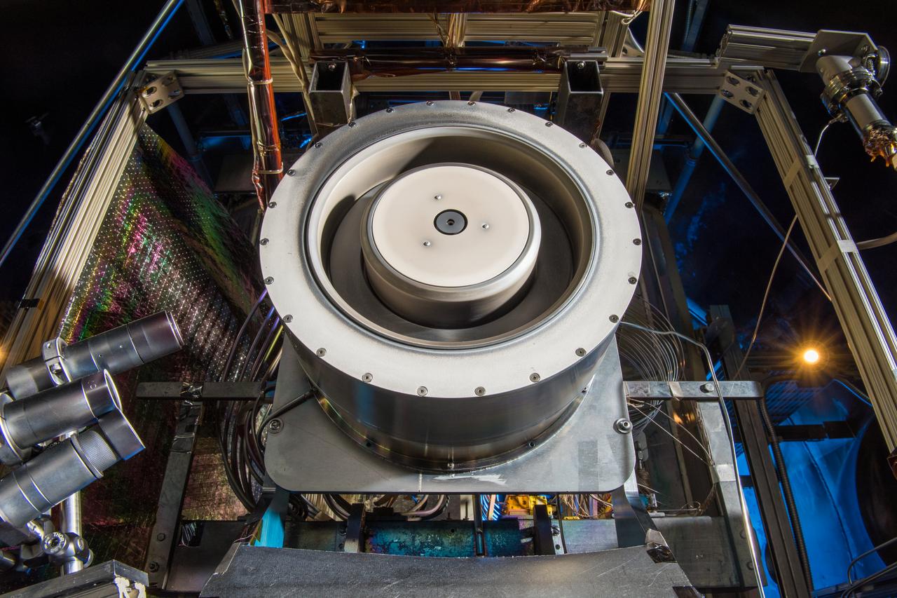
Hall Thruster in Tank 5
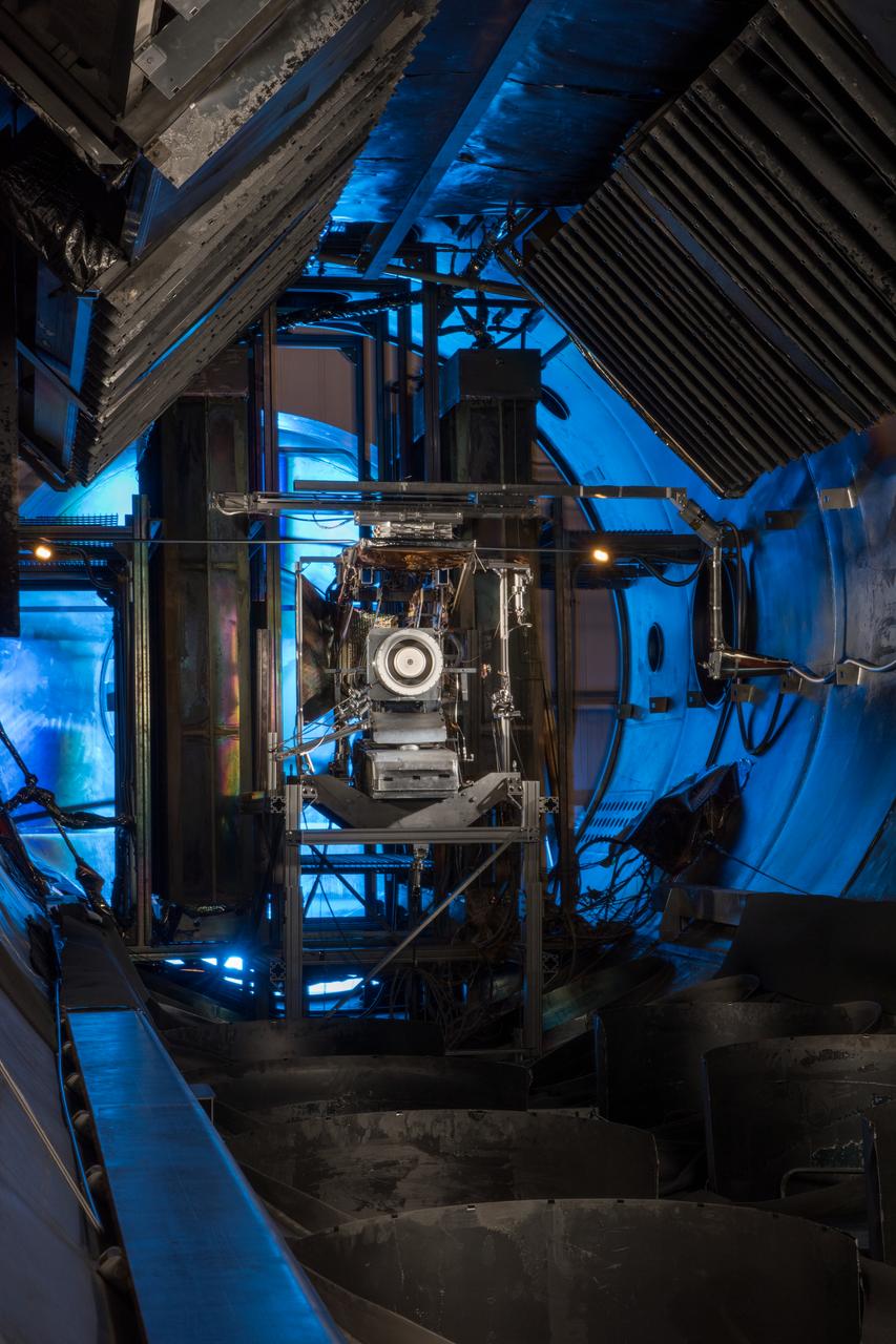
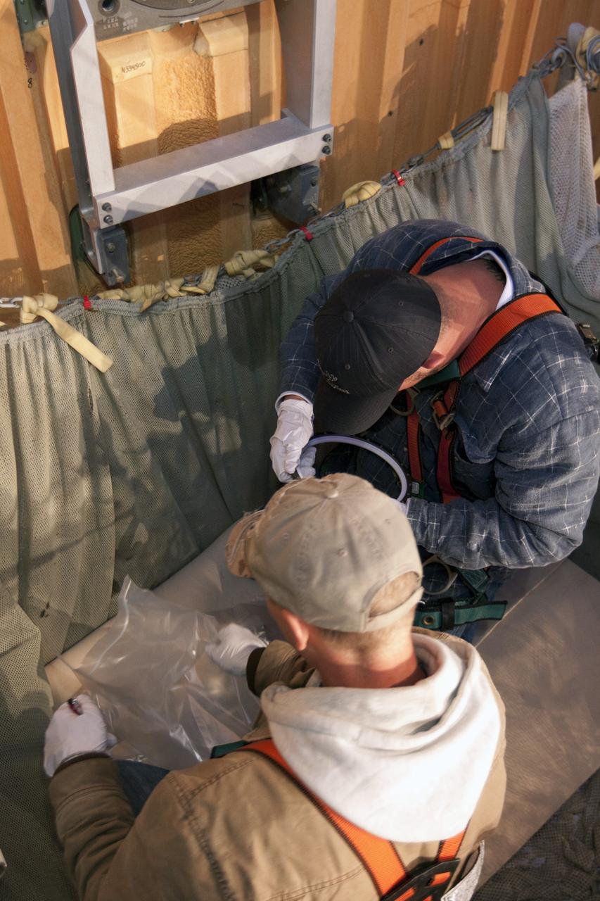
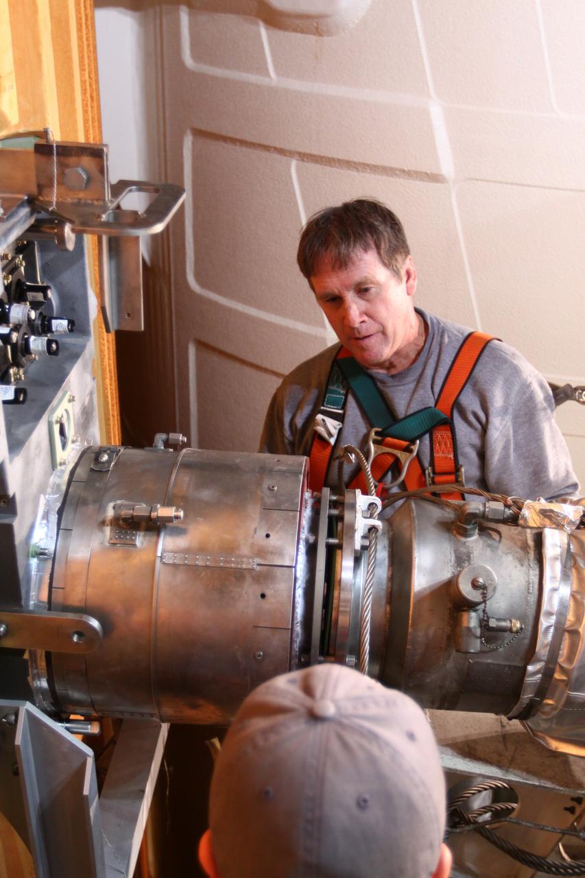
Post Ion Engine Test Documentation of Tank 5 Interior
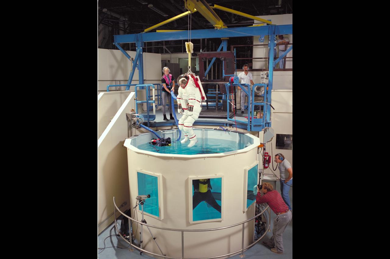
AX-5 SPACE SUIT TESTING AMES NEUTRAL BUOYANCY TANK (NBT) WITH VIC VYKUKAL
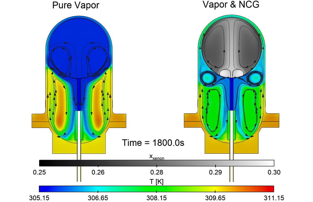
jsc2025e067420 (8/5/2025) --- Simulations of the effects of noncondensable gas on the flow and thermal structures that develop in a fuel tank in microgravity for the ZBOT-NC investigation. On the left, simulation of a tank with pure fluid and on the right, one with a fluid and gas. Credit: Case Western Reserve University
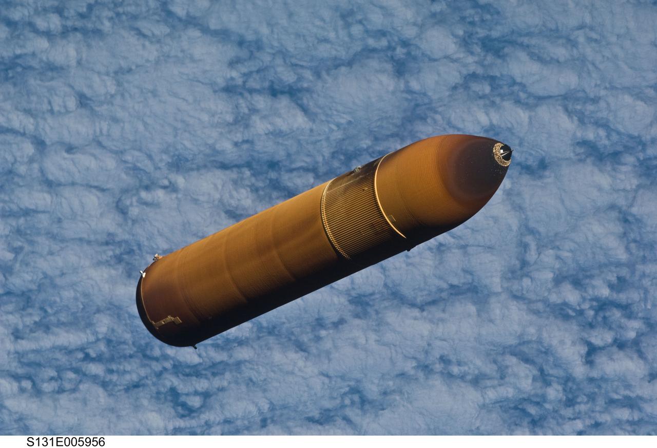
S131-E-005956 (5 April 2010) --- Backdropped by a cloud-covered part of Earth, the STS-131 external fuel tank (ET) begins its relative separation from the Space Shuttle Discovery following launch.
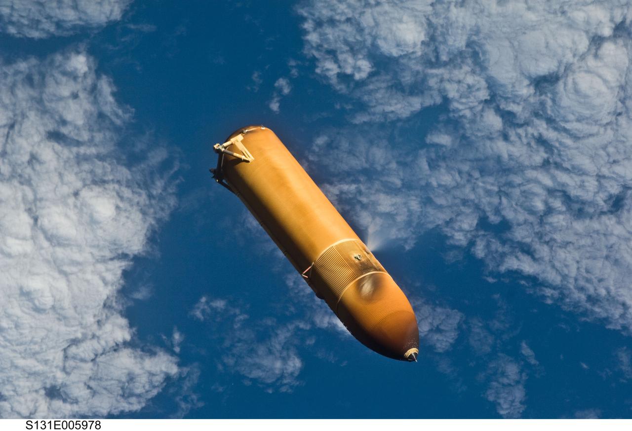
S131-E-005978 (5 April 2010) --- Backdropped by a blue and white part of Earth, the STS-131 external fuel tank (ET) begins its relative separation from the Space Shuttle Discovery following launch.
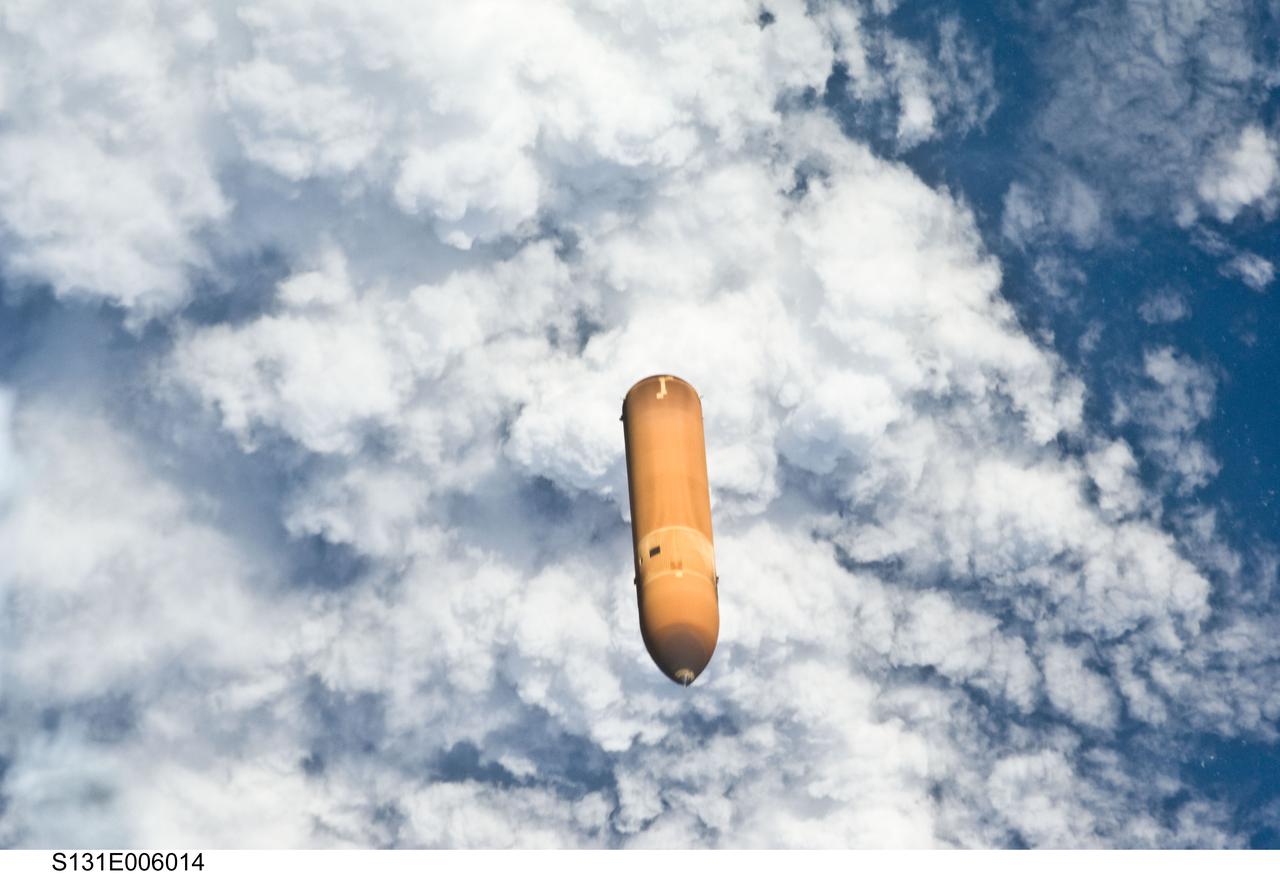
S131-E-006014 (5 April 2010) --- Backdropped by a cloud-covered part of Earth, the STS-131 external fuel tank (ET) begins its relative separation from the Space Shuttle Discovery following launch.
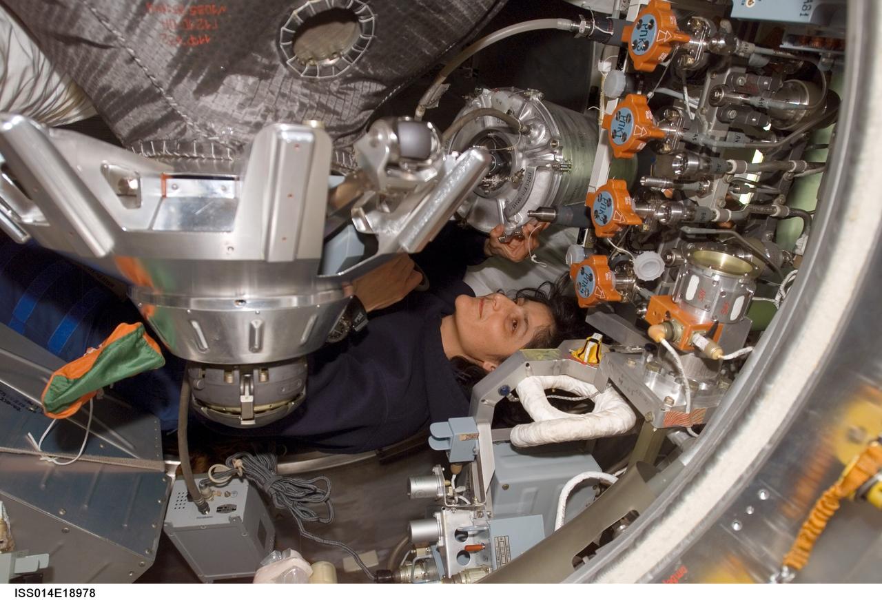
ISS014-E-18978 (5 April 2007) --- Astronaut Sunita L. Williams, Expedition 14 flight engineer, works with water tanks in the Progress 24 spacecraft docked to the International Space Station.
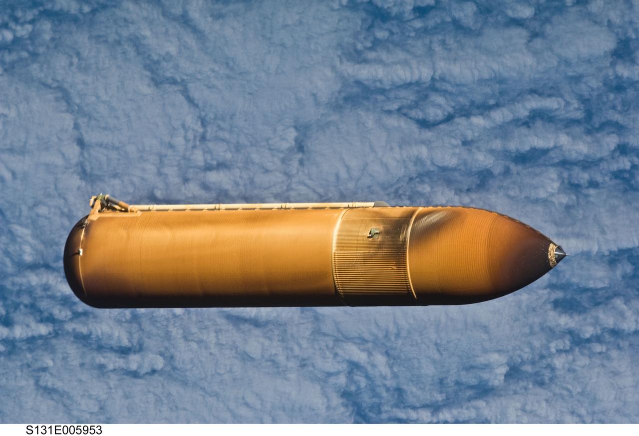
S131-E-005953 (5 April 2010) --- Backdropped by a cloud-covered part of Earth, the STS-131 external fuel tank (ET) begins its relative separation from the Space Shuttle Discovery following launch.
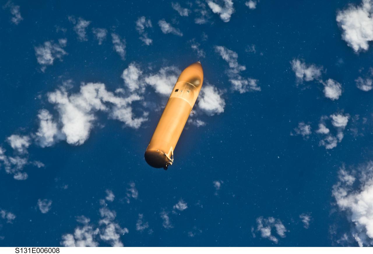
S131-E-006008 (5 April 2010) --- Backdropped by a blue and white part of Earth, the STS-131 external fuel tank (ET) begins its relative separation from the Space Shuttle Discovery following launch.
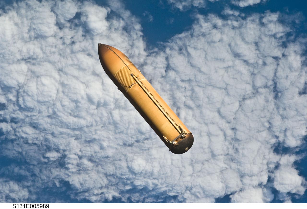
S131-E-005989 (5 April 2010) --- Backdropped by a blue and white part of Earth, the STS-131 external fuel tank (ET) begins its relative separation from the Space Shuttle Discovery following launch.
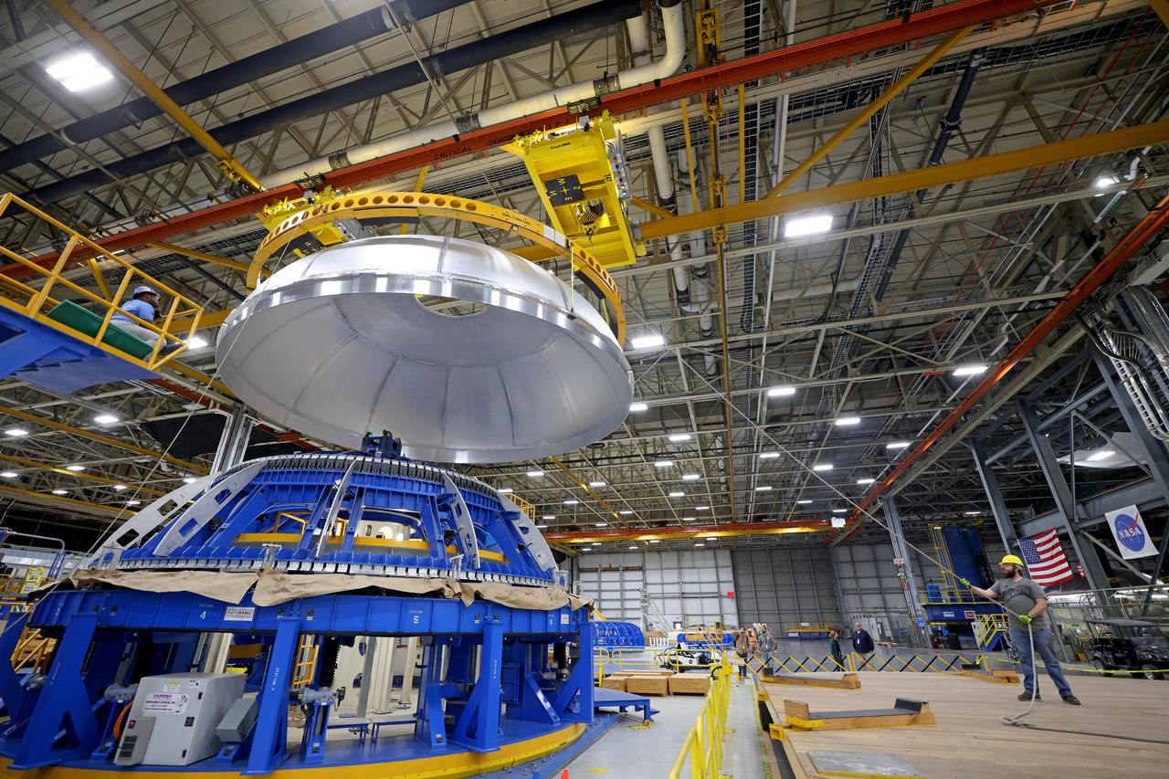
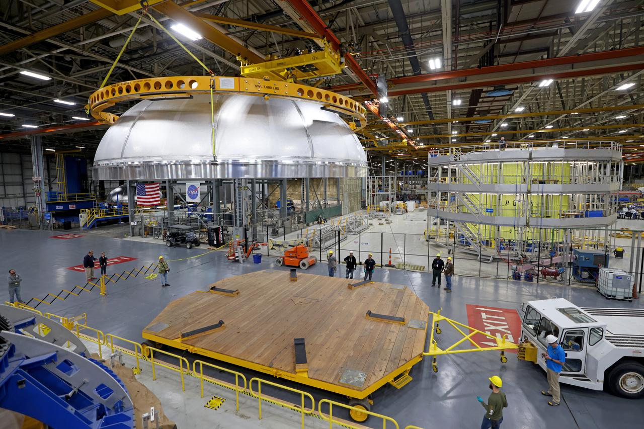
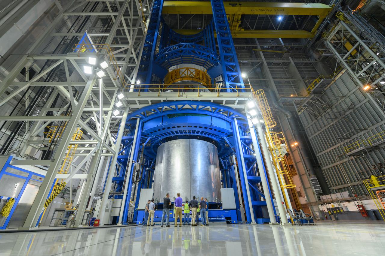
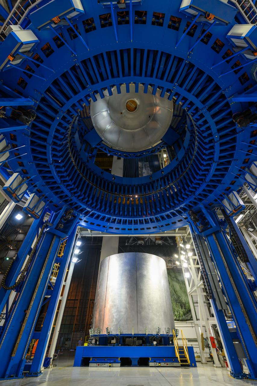
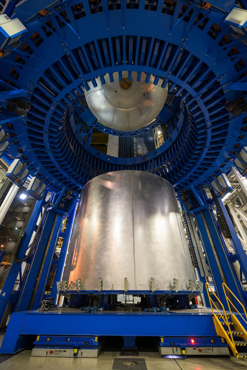
This imagery shows how technicians at NASA’s Michoud Assembly Facility moved the aft dome of the liquid oxygen tank for NASA’s SLS (Space Launch System) rocket for the next phase of production inside the Vertical Assembly center Dec. 5. The dome will form part of the core stage that will power NASA’s Artemis III mission. Engineers will soon rotate the dome to attach it to the previously joined forward dome and aft barrel segments using friction-stir welding. The liquid oxygen tank is one of five major components that make up the SLS rocket’s core stage. Together with the forward skirt, intertank, liquid hydrogen tank, engine section, along with the four RS-25 engines at its base, the 212-foot core stage will help power NASA’s Artemis missions to the Moon. Image credit: NASA/Michael DeMocker

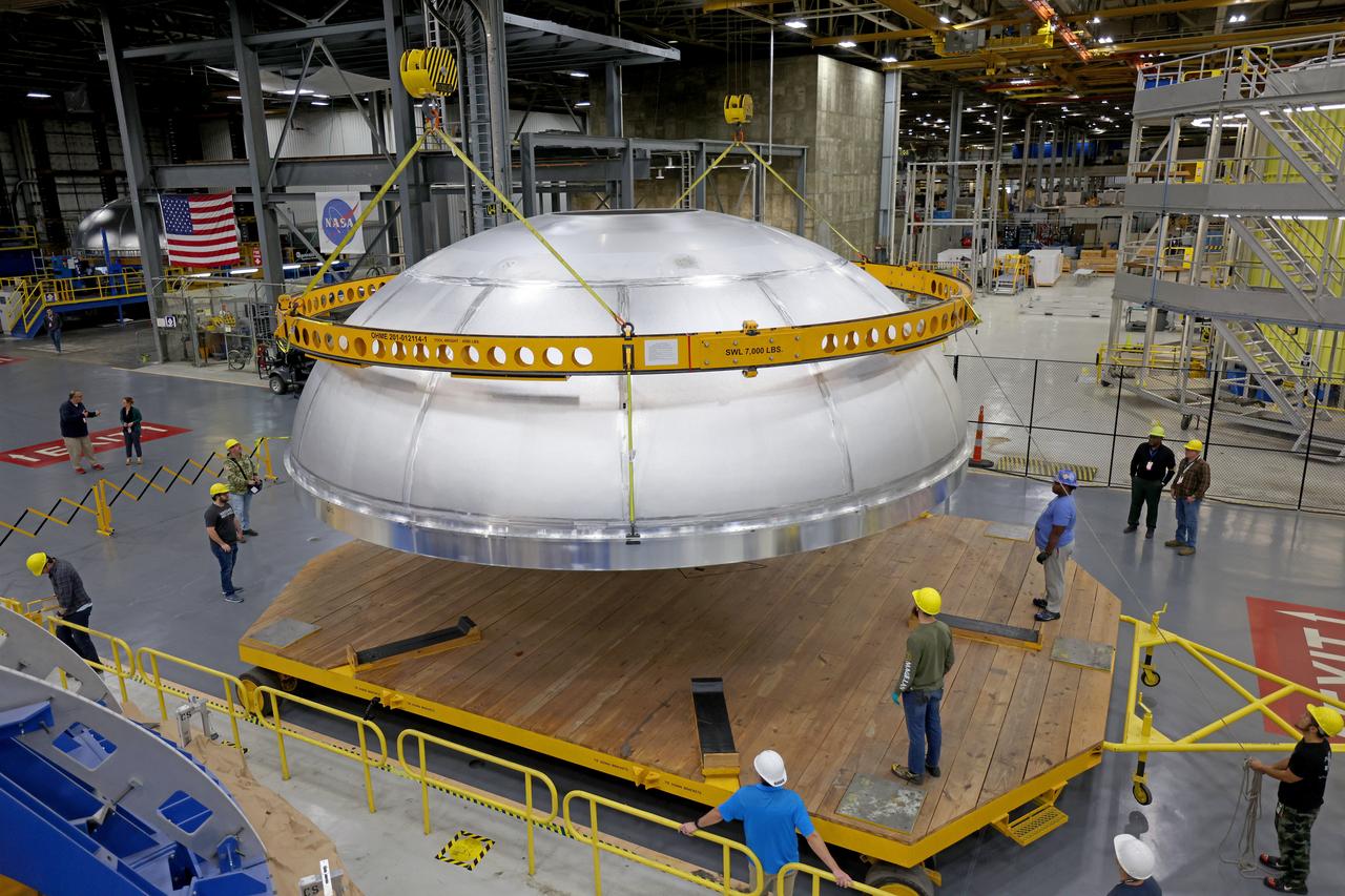
This imagery shows how technicians at NASA’s Michoud Assembly Facility moved the aft dome of the liquid oxygen tank for NASA’s SLS (Space Launch System) rocket for the next phase of production inside the Vertical Assembly center Dec. 5. The dome will form part of the core stage that will power NASA’s Artemis III mission. Engineers will soon rotate the dome to attach it to the previously joined forward dome and aft barrel segments using friction-stir welding. The liquid oxygen tank is one of five major components that make up the SLS rocket’s core stage. Together with the forward skirt, intertank, liquid hydrogen tank, engine section, along with the four RS-25 engines at its base, the 212-foot core stage will help power NASA’s Artemis missions to the Moon.

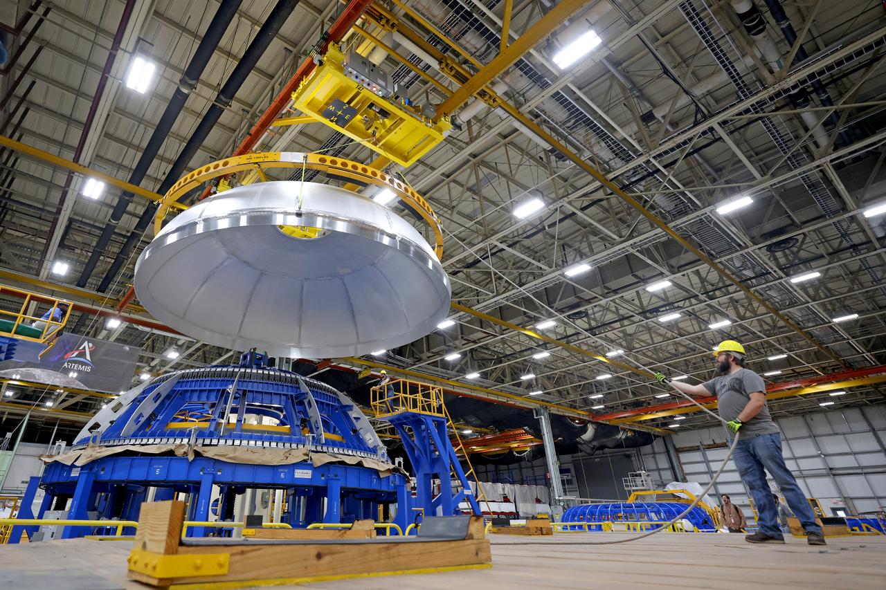
This imagery shows how technicians at NASA’s Michoud Assembly Facility moved the aft dome of the liquid oxygen tank for NASA’s SLS (Space Launch System) rocket for the next phase of production inside the Vertical Assembly center Dec. 5. The dome will form part of the core stage that will power NASA’s Artemis III mission. Engineers will soon rotate the dome to attach it to the previously joined forward dome and aft barrel segments using friction-stir welding. The liquid oxygen tank is one of five major components that make up the SLS rocket’s core stage. Together with the forward skirt, intertank, liquid hydrogen tank, engine section, along with the four RS-25 engines at its base, the 212-foot core stage will help power NASA’s Artemis missions to the Moon.

This imagery shows how technicians at NASA’s Michoud Assembly Facility moved the aft dome of the liquid oxygen tank for NASA’s SLS (Space Launch System) rocket for the next phase of production inside the Vertical Assembly center Dec. 5. The dome will form part of the core stage that will power NASA’s Artemis III mission. Engineers will soon rotate the dome to attach it to the previously joined forward dome and aft barrel segments using friction-stir welding. The liquid oxygen tank is one of five major components that make up the SLS rocket’s core stage. Together with the forward skirt, intertank, liquid hydrogen tank, engine section, along with the four RS-25 engines at its base, the 212-foot core stage will help power NASA’s Artemis missions to the Moon.
This imagery shows how technicians at NASA’s Michoud Assembly Facility moved the aft dome of the liquid oxygen tank for NASA’s SLS (Space Launch System) rocket for the next phase of production inside the Vertical Assembly center Dec. 5. The dome will form part of the core stage that will power NASA’s Artemis III mission. Engineers will soon rotate the dome to attach it to the previously joined forward dome and aft barrel segments using friction-stir welding. The liquid oxygen tank is one of five major components that make up the SLS rocket’s core stage. Together with the forward skirt, intertank, liquid hydrogen tank, engine section, along with the four RS-25 engines at its base, the 212-foot core stage will help power NASA’s Artemis missions to the Moon. Image credit: NASA/Michael DeMocker
This imagery shows how technicians at NASA’s Michoud Assembly Facility moved the aft dome of the liquid oxygen tank for NASA’s SLS (Space Launch System) rocket for the next phase of production inside the Vertical Assembly center Dec. 5. The dome will form part of the core stage that will power NASA’s Artemis III mission. Engineers will soon rotate the dome to attach it to the previously joined forward dome and aft barrel segments using friction-stir welding. The liquid oxygen tank is one of five major components that make up the SLS rocket’s core stage. Together with the forward skirt, intertank, liquid hydrogen tank, engine section, along with the four RS-25 engines at its base, the 212-foot core stage will help power NASA’s Artemis missions to the Moon. Image credit: NASA/Michael DeMocker
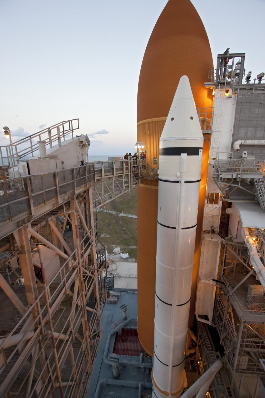
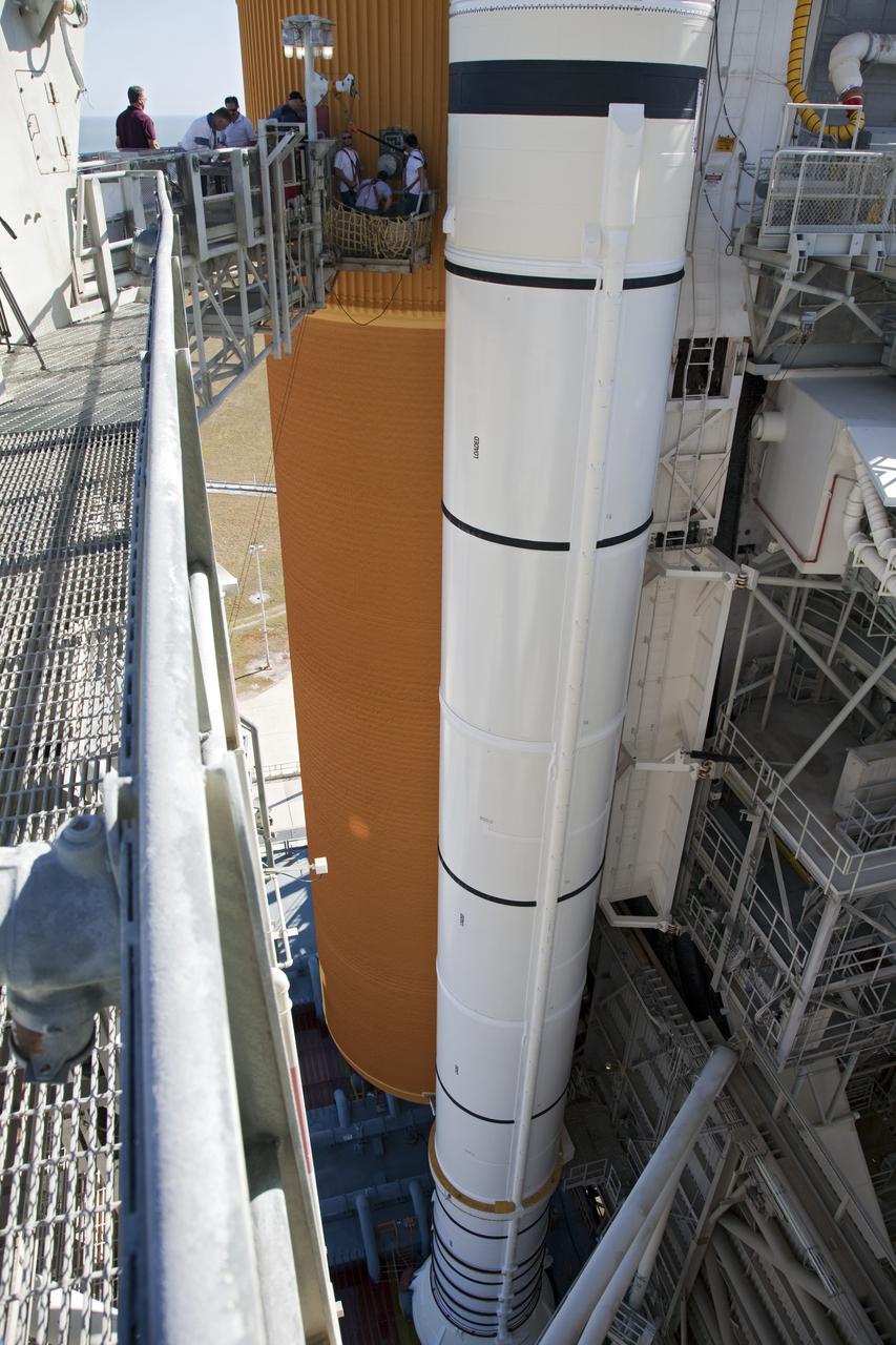
CAPE CANAVERAL, Fla. -- On Launch Pad 39A at NASA's Kennedy Space Center in Florida, technicians prepare to work inside the intertank of space shuttle Discovery's external fuel tank. Seen here are step pads that will be temporarily installed in the intertank. The intertank is unpressurized and holds most of the tank's electrical components. It sits between the liquid hydrogen tank and liquid oxygen tank. Technicians will be working inside the intertank to further analyze two cracks that were found on the tank’s metal exterior. The foam cracked during initial loading operations for space shuttle Discovery’s launch attempt on Nov. 5. The cracks are on one of the stringers, which are the composite aluminum ribs located vertically on the intertank area. Discovery's next launch attempt is no earlier than Nov. 30 at 4:02 a.m. EST. For more information on STS-133, visit www.nasa.gov/mission_pages/shuttle/shuttlemissions/sts133/. Photo credit: NASA/Jack Pfaller
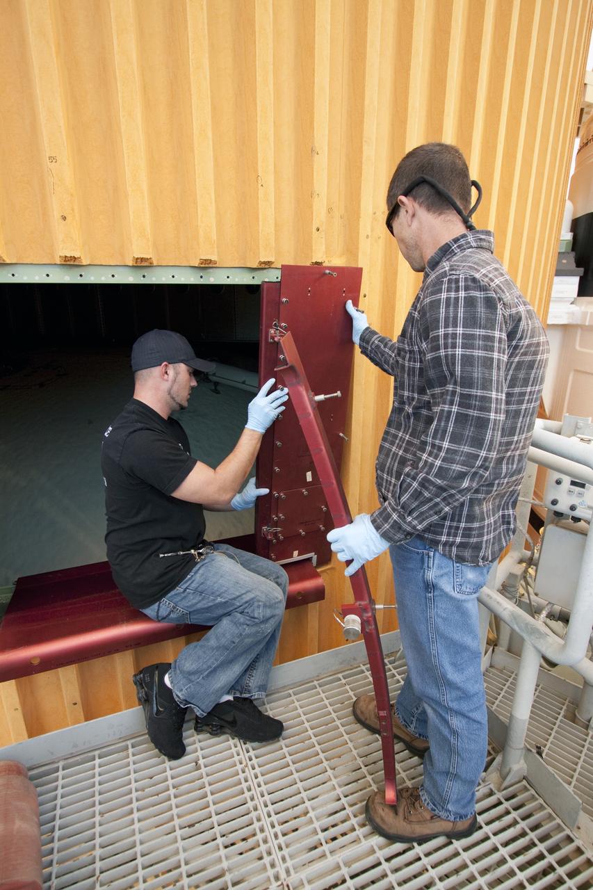
CAPE CANAVERAL, Fla. -- On Launch Pad 39A at NASA's Kennedy Space Center in Florida, technicians prepare to work inside the intertank of space shuttle Discovery's external fuel tank, which is accessible through this door. The intertank is unpressurized and holds most of the tank's electrical components. It sits between the liquid hydrogen tank and liquid oxygen tank. Technicians will be working inside the intertank to further analyze two cracks that were found on the tank’s metal exterior. The foam cracked during initial loading operations for space shuttle Discovery’s launch attempt on Nov. 5. The cracks are on one of the stringers, which are the composite aluminum ribs located vertically on the intertank area. Discovery's next launch attempt is no earlier than Nov. 30 at 4:02 a.m. EST. For more information on STS-133, visit www.nasa.gov/mission_pages/shuttle/shuttlemissions/sts133/. Photo credit: NASA/Jack Pfaller
CAPE CANAVERAL, Fla. -- On Launch Pad 39A at NASA's Kennedy Space Center in Florida, technicians prepare to work inside the intertank of space shuttle Discovery's external fuel tank, which is accessible through this door. The intertank is unpressurized and holds most of the tank's electrical components. It sits between the liquid hydrogen tank and liquid oxygen tank. Technicians will be working inside the intertank to further analyze two cracks that were found on the tank’s metal exterior. The foam cracked during initial loading operations for space shuttle Discovery’s launch attempt on Nov. 5. The cracks are on one of the stringers, which are the composite aluminum ribs located vertically on the intertank area. Discovery's next launch attempt is no earlier than Nov. 30 at 4:02 a.m. EST. For more information on STS-133, visit www.nasa.gov/mission_pages/shuttle/shuttlemissions/sts133/. Photo credit: NASA/Jack Pfaller
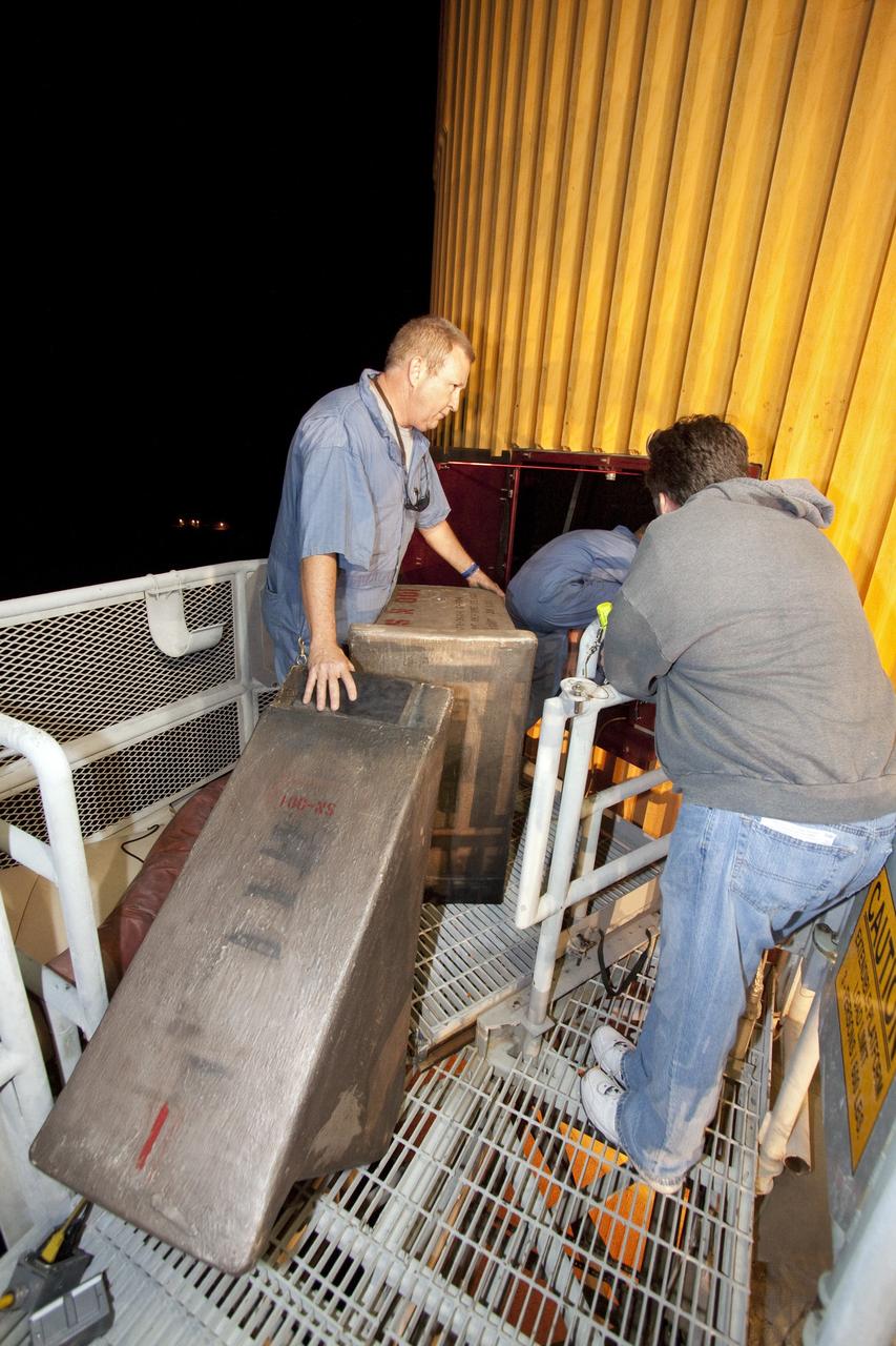
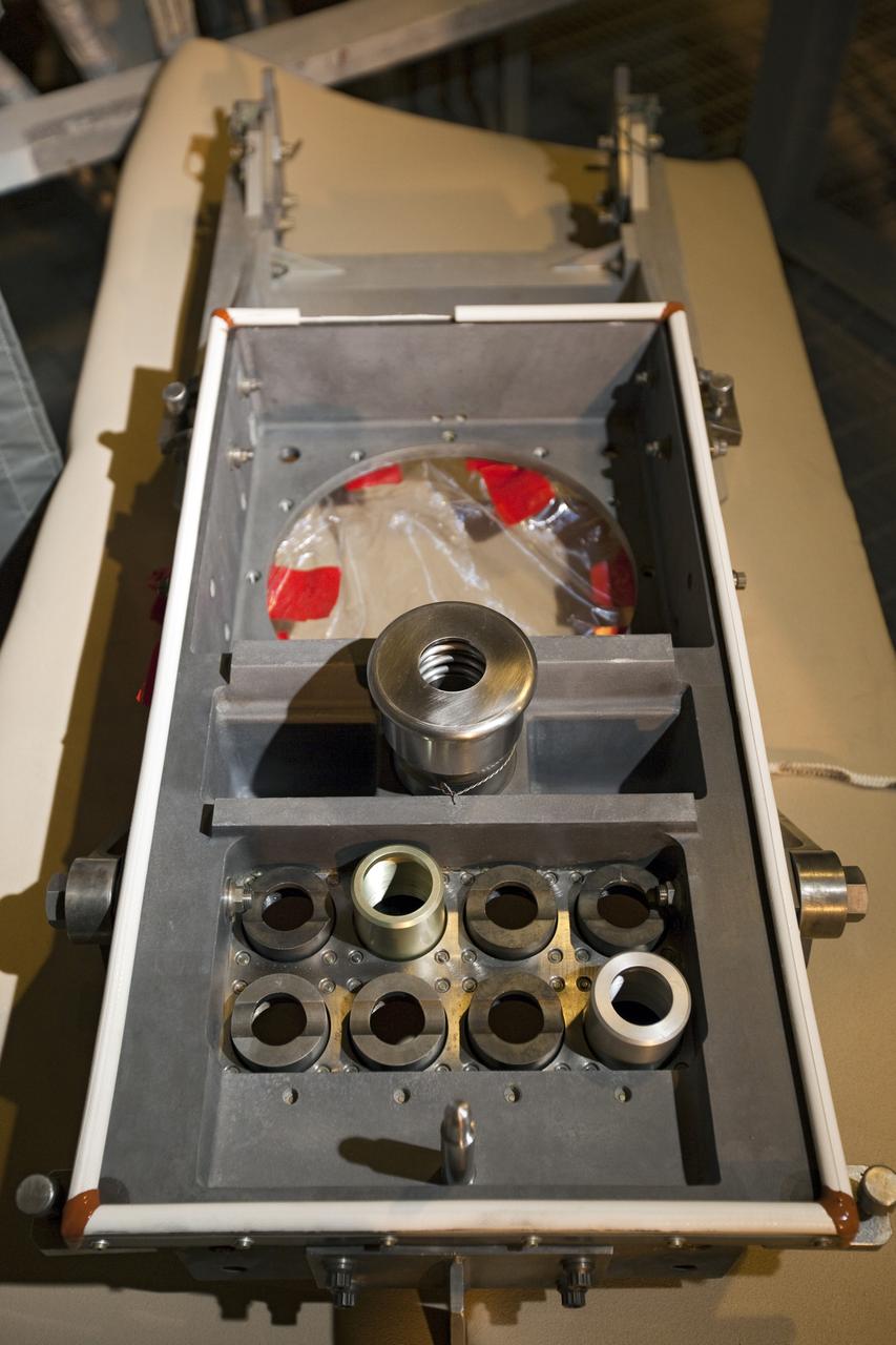
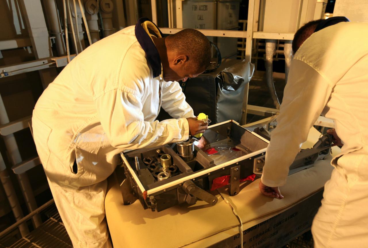
CAPE CANAVERAL, Fla. -- On Launch Pad 39A at NASA's Kennedy Space Center in Florida, technicians take temporary step pads into the intertank of space shuttle Discovery's external fuel tank. The intertank is unpressurized and holds most of the tank's electrical components. It sits between the liquid hydrogen tank and liquid oxygen tank. Technicians will be working inside the intertank to further analyze two cracks that were found on the tank’s metal exterior. The foam cracked during initial loading operations for space shuttle Discovery’s launch attempt on Nov. 5. The cracks are on one of the stringers, which are the composite aluminum ribs located vertically on the intertank area. Discovery's next launch attempt is no earlier than Nov. 30 at 4:02 a.m. EST. For more information on STS-133, visit www.nasa.gov/mission_pages/shuttle/shuttlemissions/sts133/. Photo credit: NASA/Jack Pfaller
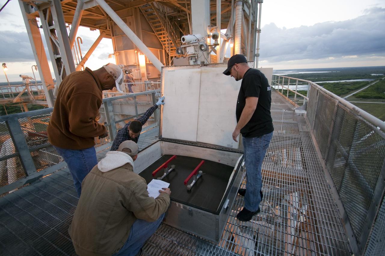
CAPE CANAVERAL, Fla. -- On Launch Pad 39A at NASA's Kennedy Space Center in Florida, technicians prepare to work inside the intertank of space shuttle Discovery's external fuel tank. Seen here are step pads that will be temporarily installed in the intertank. The intertank is unpressurized and holds most of the tank's electrical components. It sits between the liquid hydrogen tank and liquid oxygen tank. Technicians will be working inside the intertank to further analyze two cracks that were found on the tank’s metal exterior. The foam cracked during initial loading operations for space shuttle Discovery’s launch attempt on Nov. 5. The cracks are on one of the stringers, which are the composite aluminum ribs located vertically on the intertank area. Discovery's next launch attempt is no earlier than Nov. 30 at 4:02 a.m. EST. For more information on STS-133, visit www.nasa.gov/mission_pages/shuttle/shuttlemissions/sts133/. Photo credit: NASA/Jack Pfaller
CAPE CANAVERAL, Fla. -- On Launch Pad 39A at NASA's Kennedy Space Center in Florida, technicians prepare to work inside the intertank of space shuttle Discovery's external fuel tank. The intertank is unpressurized and holds most of the tank's electrical components. It sits between the liquid hydrogen tank and liquid oxygen tank. Technicians will be working inside the intertank to further analyze two cracks that were found on the tank’s metal exterior. The foam cracked during initial loading operations for space shuttle Discovery’s launch attempt on Nov. 5. The cracks are on one of the stringers, which are the composite aluminum ribs located vertically on the intertank area. Discovery's next launch attempt is no earlier than Nov. 30 at 4:02 a.m. EST. For more information on STS-133, visit www.nasa.gov/mission_pages/shuttle/shuttlemissions/sts133/. Photo credit: NASA/Jack Pfaller
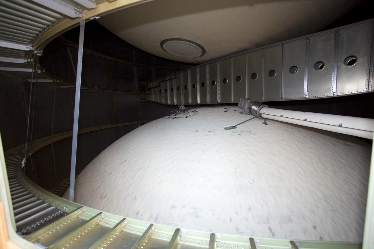
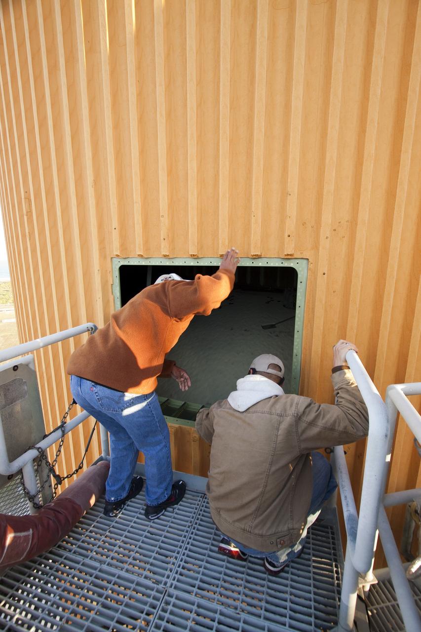
CAPE CANAVERAL, Fla. -- On Launch Pad 39A at NASA's Kennedy Space Center in Florida, this view gives a look inside the intertank of space shuttle Discovery's external fuel tank. The intertank is unpressurized and holds most of the tank's electrical components. It sits between the liquid hydrogen tank, below, and liquid oxygen tank, above. Technicians will be working inside the intertank to further analyze two cracks that were found on the tank’s metal exterior. The foam cracked during initial loading operations for space shuttle Discovery’s launch attempt on Nov. 5. The cracks are on one of the stringers, which are the composite aluminum ribs located vertically on the intertank area. Discovery's next launch attempt is no earlier than Nov. 30 at 4:02 a.m. EST. For more information on STS-133, visit www.nasa.gov/mission_pages/shuttle/shuttlemissions/sts133/. Photo credit: NASA/Jack Pfaller
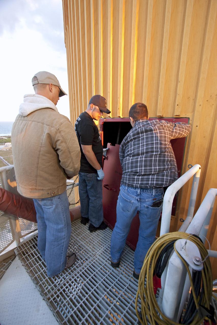
CAPE CANAVERAL, Fla. -- On Launch Pad 39A at NASA's Kennedy Space Center in Florida, technicians prepare to work inside the intertank of space shuttle Discovery's external fuel tank, which is accessible through this door. The intertank is unpressurized and holds most of the tank's electrical components. It sits between the liquid hydrogen tank and liquid oxygen tank. Technicians will be working inside the intertank to further analyze two cracks that were found on the tank’s metal exterior. The foam cracked during initial loading operations for space shuttle Discovery’s launch attempt on Nov. 5. The cracks are on one of the stringers, which are the composite aluminum ribs located vertically on the intertank area. Discovery's next launch attempt is no earlier than Nov. 30 at 4:02 a.m. EST. For more information on STS-133, visit www.nasa.gov/mission_pages/shuttle/shuttlemissions/sts133/. Photo credit: NASA/Jack Pfaller
CAPE CANAVERAL, Fla. -- On Launch Pad 39A at NASA's Kennedy Space Center in Florida, technicians prepare to work inside the intertank of space shuttle Discovery's external fuel tank. The intertank is unpressurized and holds most of the tank's electrical components. It sits between the liquid hydrogen tank and liquid oxygen tank. Technicians will be working inside the intertank to further analyze two cracks that were found on the tank’s metal exterior. The foam cracked during initial loading operations for space shuttle Discovery’s launch attempt on Nov. 5. The cracks are on one of the stringers, which are the composite aluminum ribs located vertically on the intertank area. Discovery's next launch attempt is no earlier than Nov. 30 at 4:02 a.m. EST. For more information on STS-133, visit www.nasa.gov/mission_pages/shuttle/shuttlemissions/sts133/. Photo credit: NASA/Jack Pfaller
CAPE CANAVERAL, Fla. -- On Launch Pad 39A at NASA's Kennedy Space Center in Florida, technicians prepare to work inside the intertank of space shuttle Discovery's external fuel tank. Seen here are step pads that will be temporarily installed in the intertank. The intertank is unpressurized and holds most of the tank's electrical components. It sits between the liquid hydrogen tank and liquid oxygen tank. Technicians will be working inside the intertank to further analyze two cracks that were found on the tank’s metal exterior. The foam cracked during initial loading operations for space shuttle Discovery’s launch attempt on Nov. 5. The cracks are on one of the stringers, which are the composite aluminum ribs located vertically on the intertank area. Discovery's next launch attempt is no earlier than Nov. 30 at 4:02 a.m. EST. For more information on STS-133, visit www.nasa.gov/mission_pages/shuttle/shuttlemissions/sts133/. Photo credit: NASA/Jack Pfaller

CAPE CANAVERAL, Fla. -- On Launch Pad 39A at NASA's Kennedy Space Center in Florida, technicians will access the intertank of space shuttle Discovery's external fuel tank through this door. The intertank is unpressurized and holds most of the tank's electrical components. It sits between the liquid hydrogen tank and liquid oxygen tank. Technicians will be working inside the intertank to further analyze two cracks that were found on the tank’s metal exterior. The foam cracked during initial loading operations for space shuttle Discovery’s launch attempt on Nov. 5. The cracks are on one of the stringers, which are the composite aluminum ribs located vertically on the intertank area. Discovery's next launch attempt is no earlier than Nov. 30 at 4:02 a.m. EST. For more information on STS-133, visit www.nasa.gov/mission_pages/shuttle/shuttlemissions/sts133/. Photo credit: NASA/Jack Pfaller
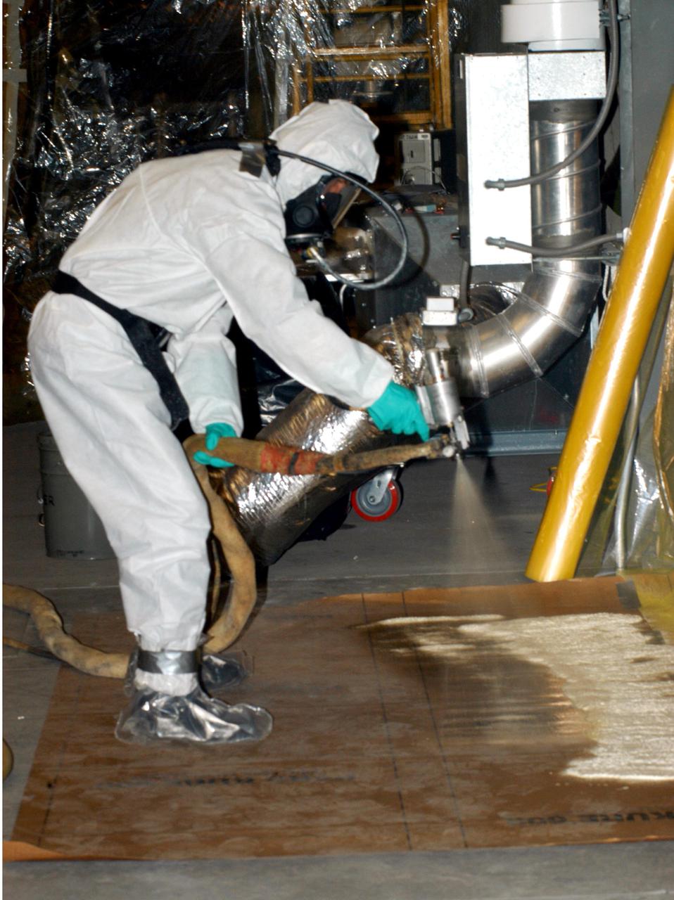
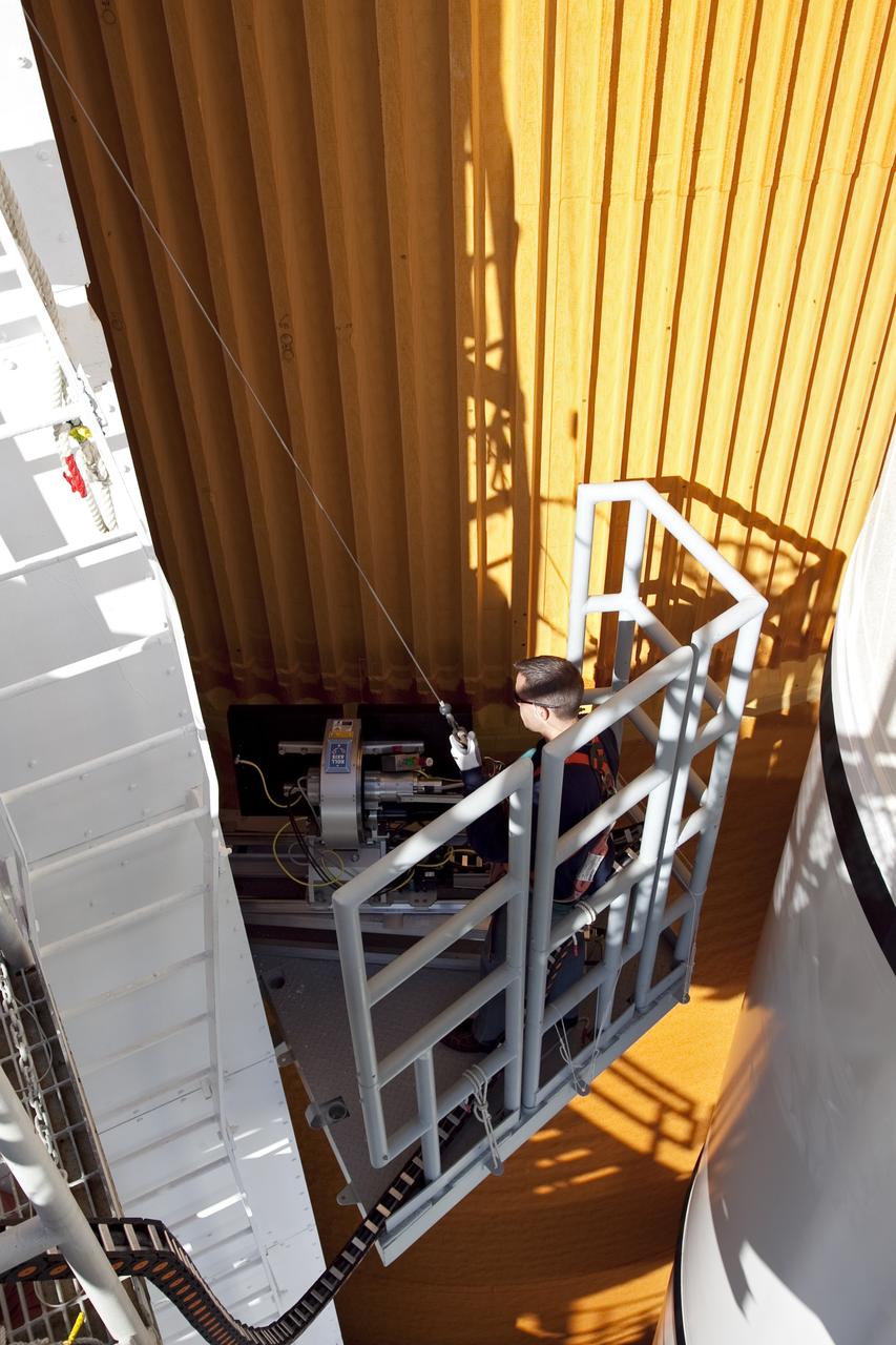
KENNEDY SPACE CENTER, FLA. - In the Vehicle Assembly Building, United Space Alliance technician Rob Williams tests the spray gun before starting aft hard-point closeout spray on the External Tank (ET).The spray is being applied on an area of the tank where the ET is mated to the transporter. Foam is not applied to that area at the Michoud Assembly Facility in Louisiana to avoid damage to the foam during travel. The ET, which arrived at KSC Jan. 5, is in the checkout cell for final processing. The tank is scheduled to fly on Space Shuttle Discovery on Return to Flight mission STS-114. The launch window is May 12 to June 3.
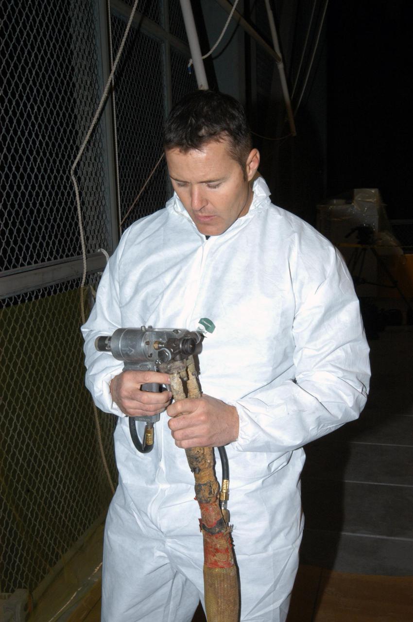
KENNEDY SPACE CENTER, FLA. - In the Vehicle Assembly Building, United Space Alliance technician Ed Carillion attaches the foam spray nozzle to the spray gun to be used for the aft hard-point closeout spray on the External Tank (ET). The spray is being applied on an area of the tank where the ET is mated to the transporter. Foam is not applied to that area at the Michoud Assembly Facility in Louisiana to avoid damage to the foam during travel. The ET, which arrived at KSC Jan. 5, is in the checkout cell for final processing. The tank is scheduled to fly on Space Shuttle Discovery on Return to Flight mission STS-114. The launch window is May 12 to June 3.
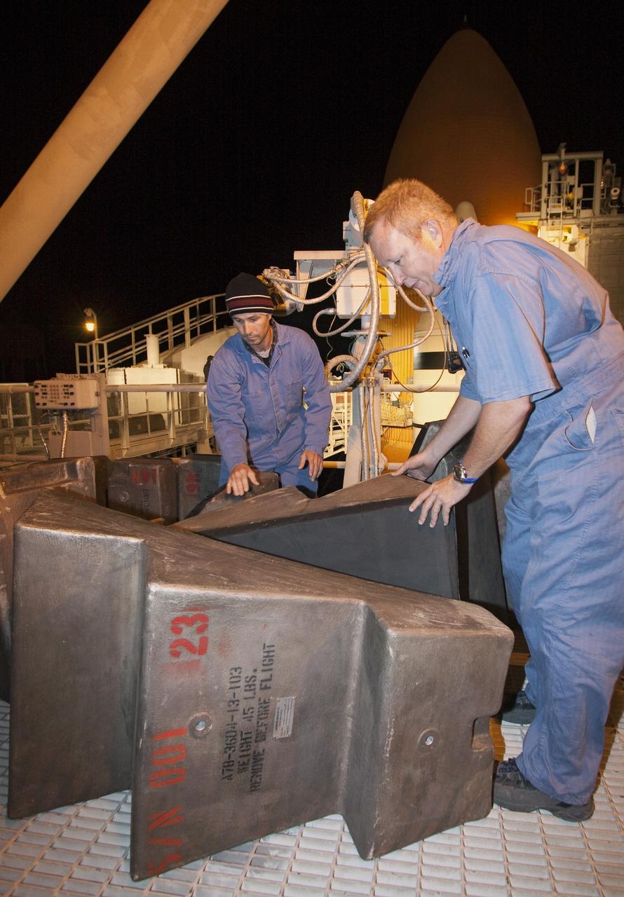
KENNEDY SPACE CENTER, FLA. -- Inside the Vehicle Assembly Building, the external tank for Endeavour is being lowered toward the mobile launcher platform for mating with the solid rocket boosters. Endeavour is currently targeted for rollover to the VAB July 5. On the lower end of the tank is seen the bipod fittings that connect the external tank to the orbiter through the shuttle's two forward attachment struts. Endeavour is the designated orbiter for mission STS-118, targeted for launch on Aug. 9 to the International Space Station. The mission will continue space station construction by delivering a third starboard truss segment, S5, as well as carrying the external stowage platform 3. Photo credit: NASA/Amanda Diller
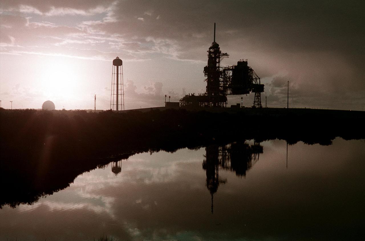
KENNEDY SPACE CENTER, Fla. -- Just after dawn, Launch Pad 39A is caught in silhouette and reflected in the water nearby. On the pad is Space Shuttle Discovery, waiting for launch on mission STS-92 Oct. 5, 2000. At the left of the pad is the 300,000-gallon water tank that is part of the sound suppression system during launches. At far left, the ball-shaped structure is a storage tank for one of the cryogenic liquid propellants of the orbiter’s main engines
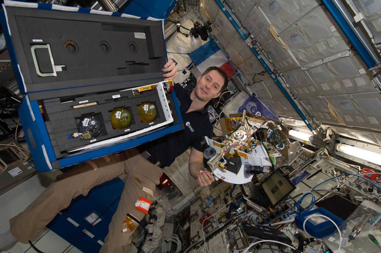
iss051e033988 (5/2/2017) --- European Space Agency (ESA) astronaut Thomas Pesquet is photographed with the Tanks Bag and Science Arm for the Fluid Dynamics in Space (FLUIDICS) experiment. Image was taken in the Columbus European Laboratory during preparations for the first run of the experiment. The FLUIDICS investigation evaluates the Center of Mass (CoM) position regarding a temperature gradient on a representation of a fuel tank. The observation of capillary wave turbulence on the surface of a fluid layer in a low-gravity environment can provide insights into measuring the existing volume in a sphere.
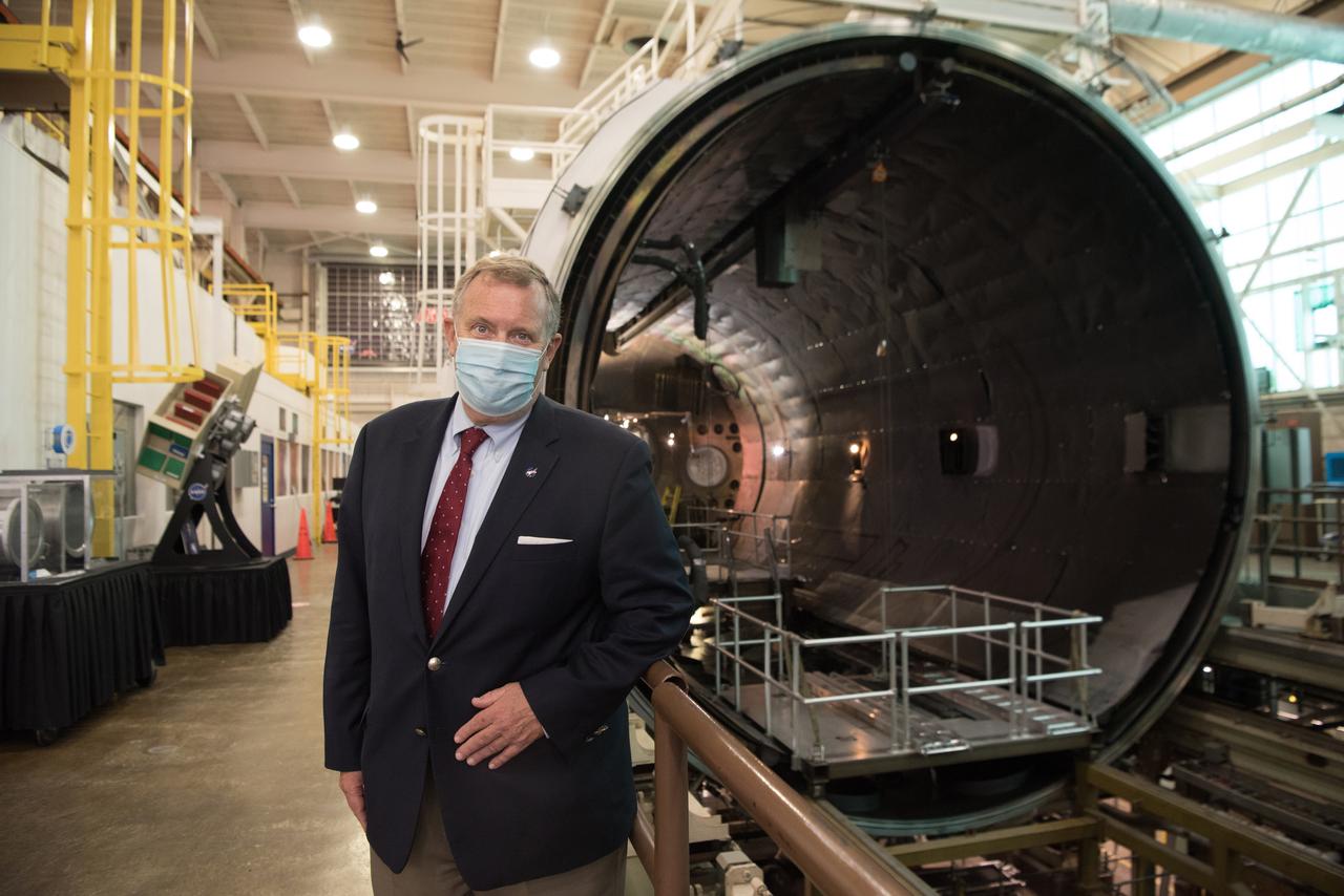
Visit to GRC by the Deputy Administrator, James Morhard
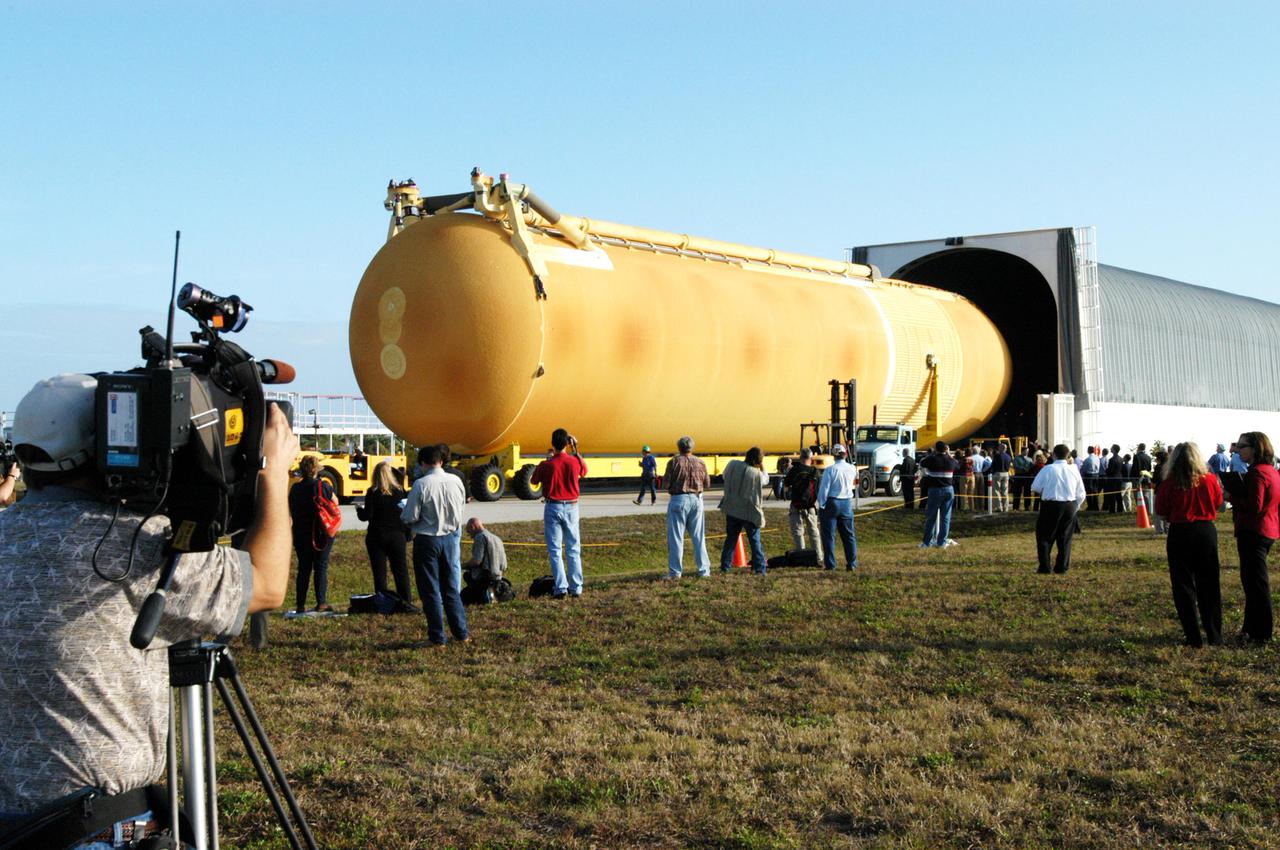
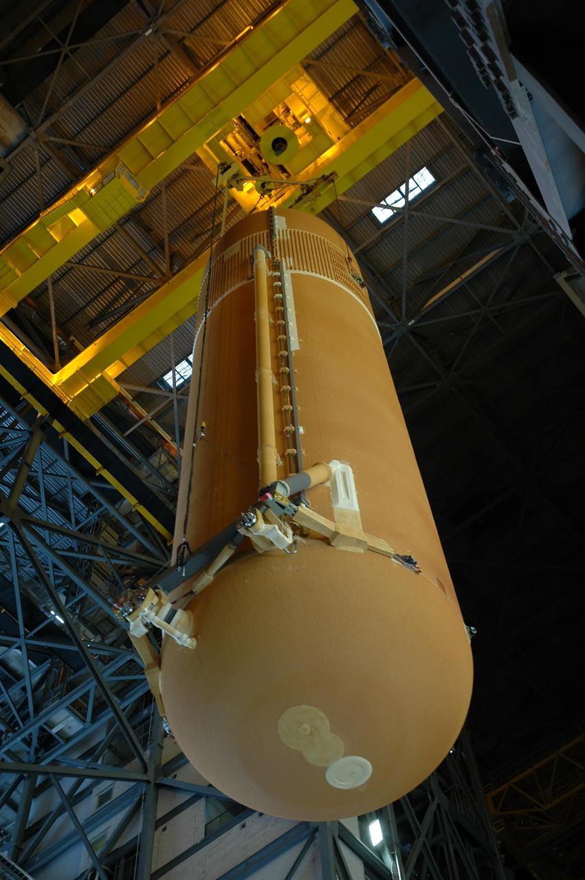
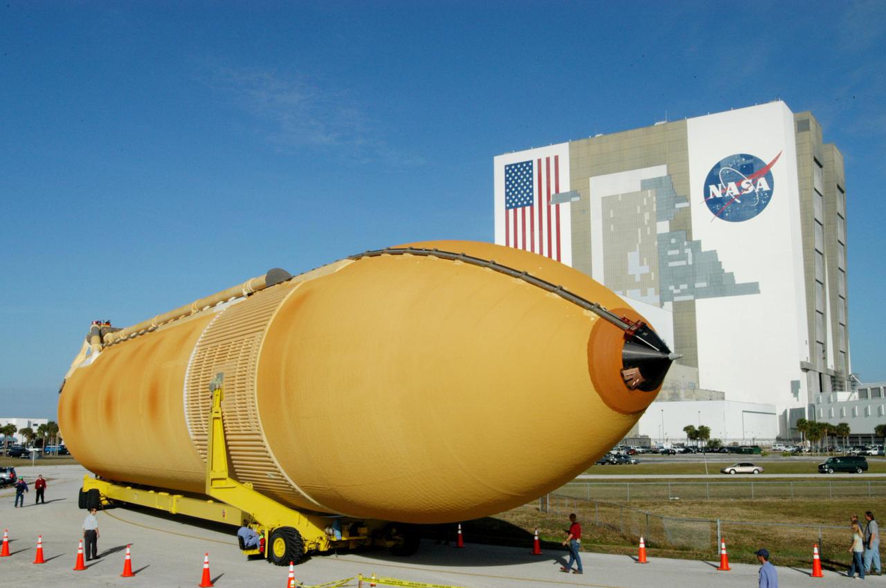
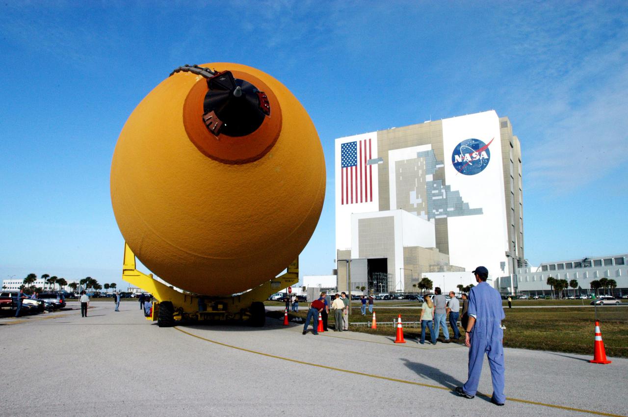
KENNEDY SPACE CENTER, FLA. - Media view the newly redesigned External Tank as it is off-loaded from the barge that carried it from the Michoud Assembly Facility in New Orleans. The tank is being transported to the Vehicle Assembly Building. The tank arrived Jan. 5 after a 900-mile sea voyage aboard NASA’s specially designed barge, Pegasus, from the Michoud Assembly Facility in New Orleans. In the transfer aisle of the VAB, the tank will be raised from a horizontal to a vertical position, then lifted high up into a storage cell, or “checkout cell,” where it will undergo inspections of the mechanical, electrical and thermal protection systems. New processing activities resulting from re-design of the tank include inspection of the bipod heater and External Tank separation camera, which includes charging the camera batteries. The tank will be then prepared for mating to the Solid Rocket Boosters. When preparations are complete, the tank will be lifted from the checkout cell, moved across the transfer aisle and into High Bay 1, where it will be lowered and attached to the boosters, which are sitting on the Mobile Launch Platform. The tank is designated for the Return to Flight mission, STS-114, targeted for a launch opportunity beginning in May. The seven-member Discovery crew will fly to the International Space Station primarily to test and evaluate new procedures for flight safety, including Space Shuttle inspection and repair techniques.
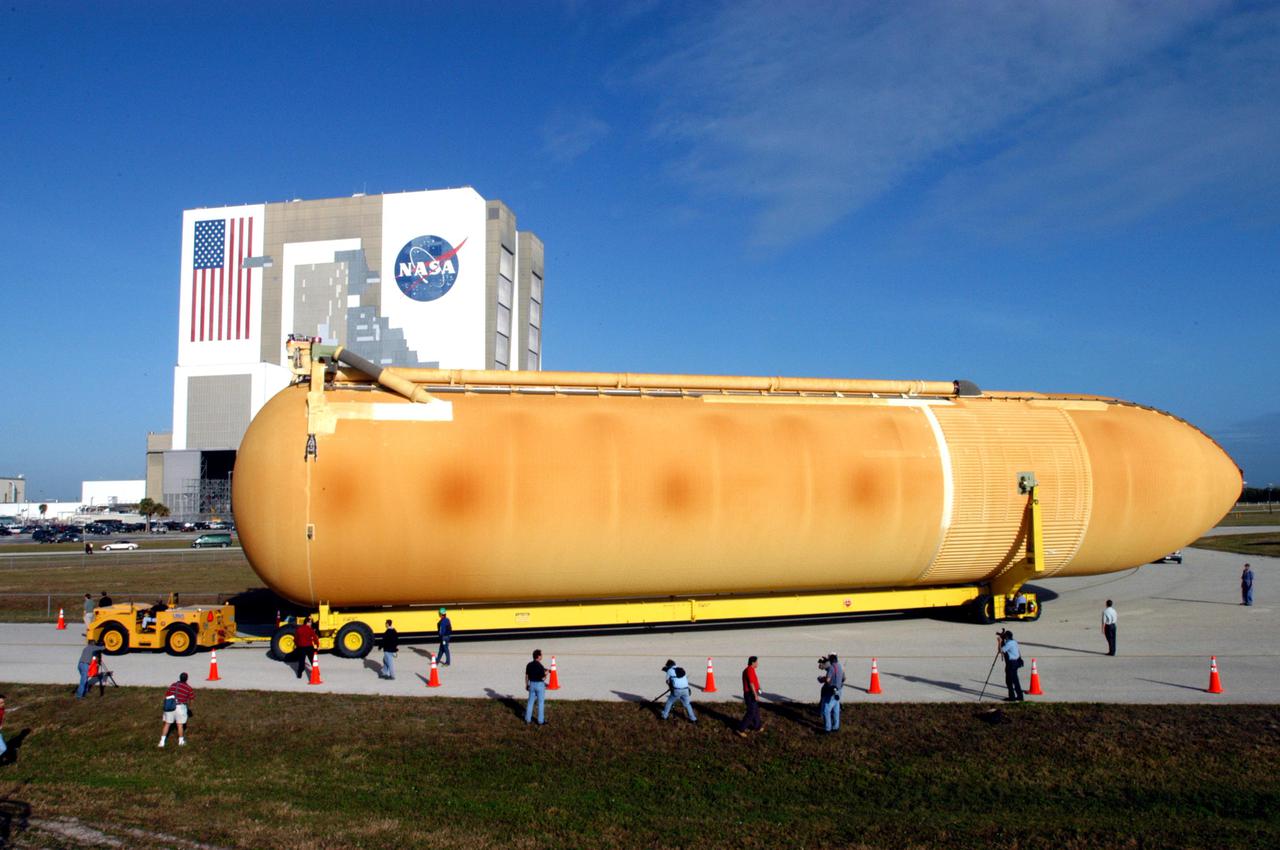
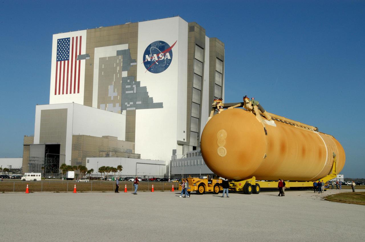
KENNEDY SPACE CENTER, FLA. - KSC employees accompany the newly redesigned External Tank as it wends its way through the parking area at the Launch Complex 39 Area Turn Basin. The tank is being moved to the Vehicle Assembly Building, seen behind it. The tank arrived Jan. 5 after a 900-mile sea voyage aboard NASA’s specially designed barge, Pegasus, from the Michoud Assembly Facility in New Orleans. In the transfer aisle of the VAB, the tank will be raised from a horizontal to a vertical position, then lifted high up into a storage cell, or “checkout cell,” where it will undergo inspections of the mechanical, electrical and thermal protection systems. New processing activities resulting from re-design of the tank include inspection of the bipod heater and External Tank separation camera, which includes charging the camera batteries. The tank will be then prepared for mating to the Solid Rocket Boosters. When preparations are complete, the tank will be lifted from the checkout cell, moved across the transfer aisle and into High Bay 1, where it will be lowered and attached to the boosters, which are sitting on the Mobile Launch Platform. The tank is designated for the Return to Flight mission, STS-114, targeted for a launch opportunity beginning in May. The seven-member Discovery crew will fly to the International Space Station primarily to test and evaluate new procedures for flight safety, including Space Shuttle inspection and repair techniques.
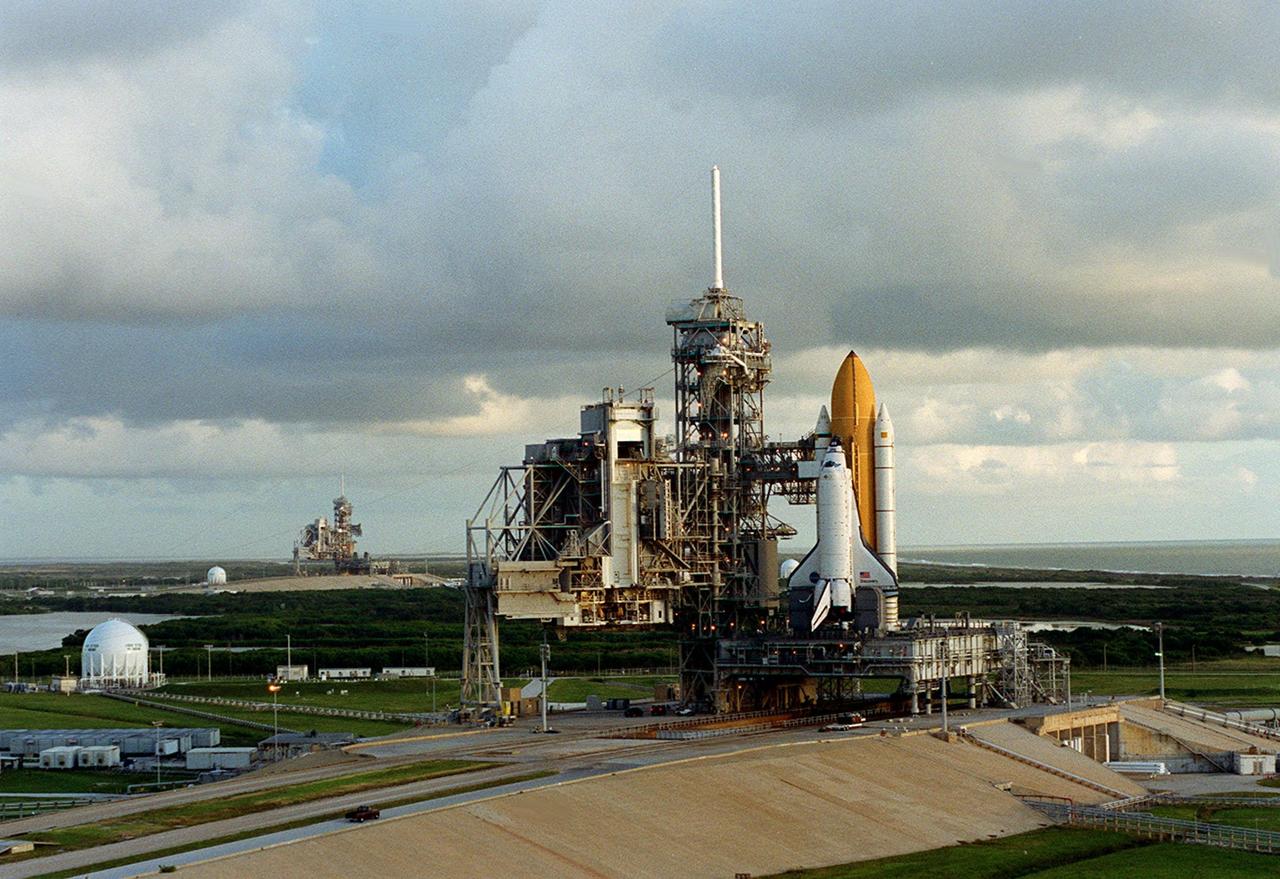
KENNEDY SPACE CENTER, Fla. -- This aerial photo captures Launch Pads 39B (left) and 39A (right). Space Shuttle Discovery waits on pad 39A for launch on mission STS-92 Oct. 5, 2000. The ball-shaped structures at left of the pads are storage tanks of the cryogenic liquid propellants for the orbiter’s main engines
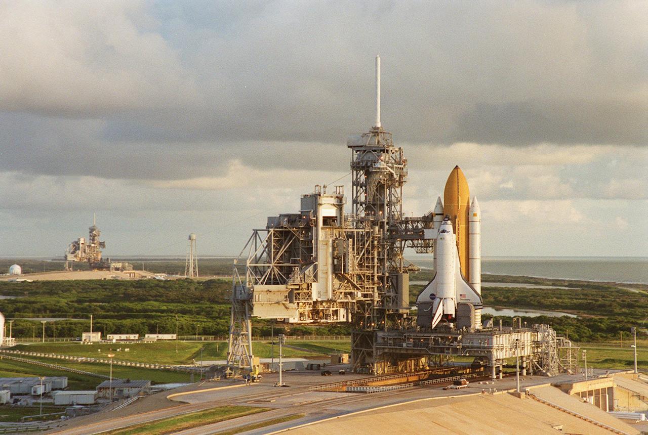
Cloudy skies form a backdrop for Launch Pads 39B (left) and 39A (foreground). Space Shuttle Discovery waits on top of the pad for its launch Oct. 5 to the International Space Station. Between the pads can be seen the 300,000-gallon water tank that provides water for the sound suppression system during launch.

KENNEDY SPACE CENTER, Fla. -- This aerial photo captures Launch Pads 39B (left) and 39A (right). Space Shuttle Discovery waits on pad 39A for launch on mission STS-92 Oct. 5, 2000. The ball-shaped structures at left of the pads are storage tanks of the cryogenic liquid propellants for the orbiter’s main engines
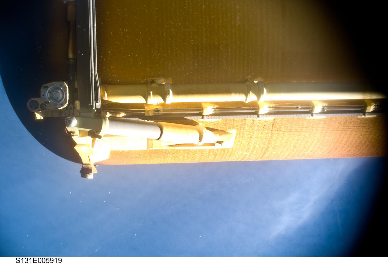
S131-E-005919 (5 April 2010) --- Space shuttle Discovery?s external fuel tank (ET) is featured in this image photographed by the umbilical well camera aboard Discovery shortly after separating from the shuttle following launch.
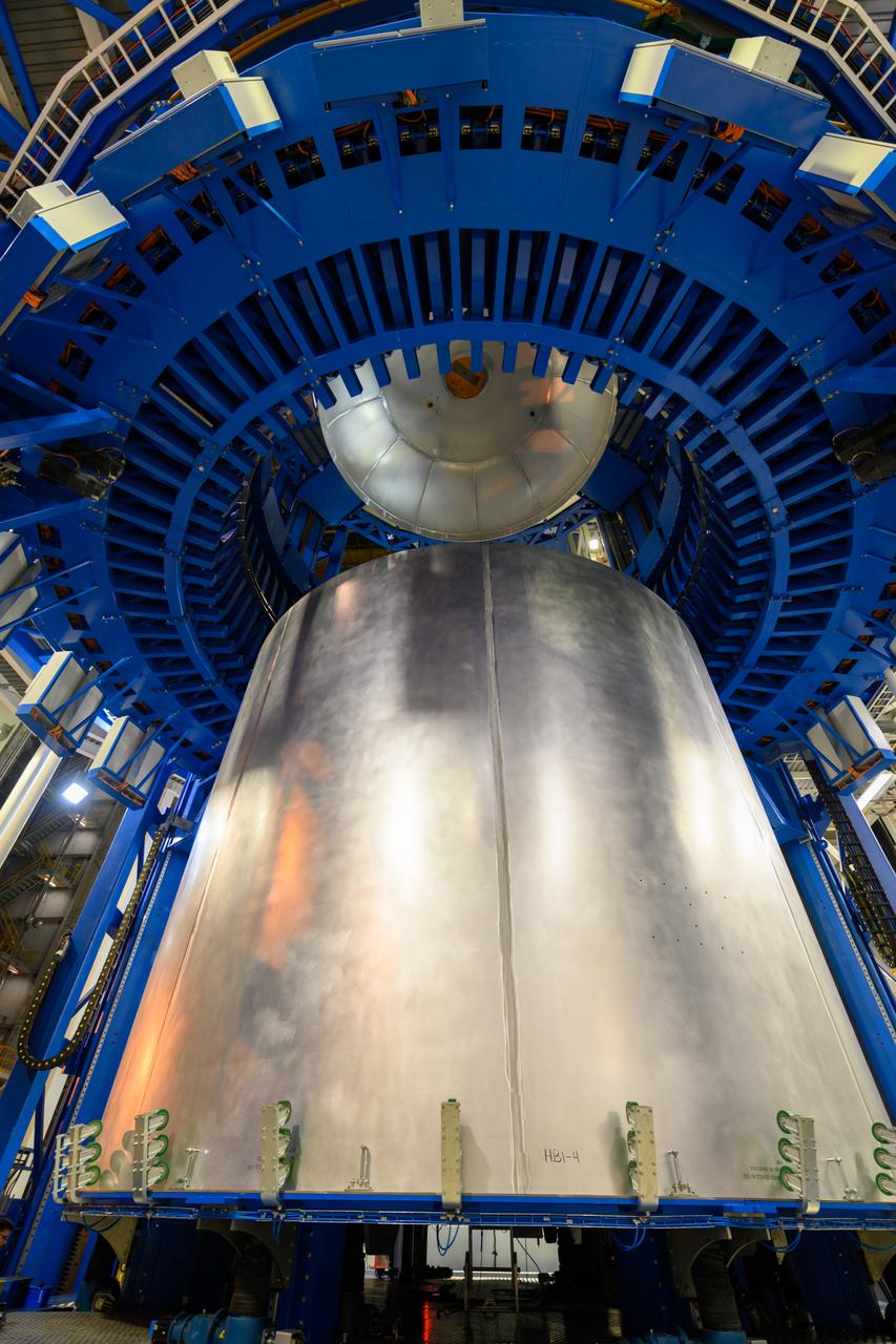
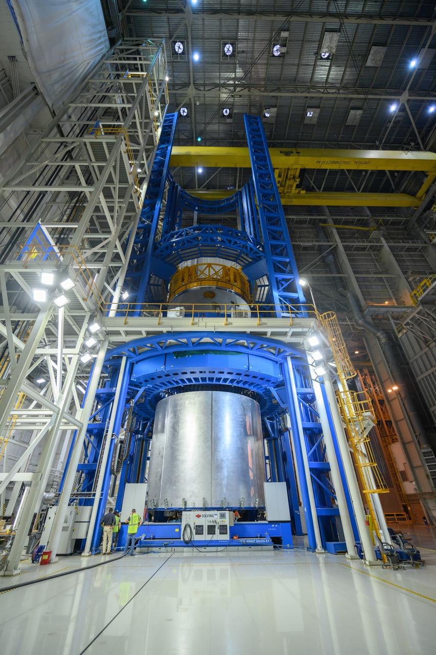
Space Launch System Corestage-2 Liquid Hydrogen(LH2) tank is under construction at NASA's Michoud Assembly Facility. Here you can see 1 of 5 barrels being loaded in the Vertical Assembly Center tool where it will be welded.
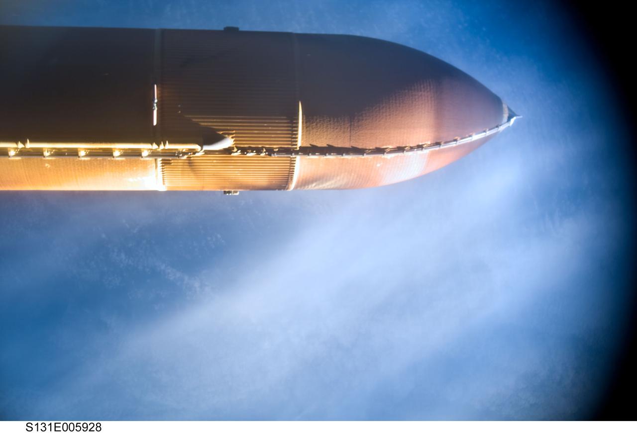
S131-E-005928 (5 April 2010) --- Space shuttle Discovery?s external fuel tank (ET) is featured in this image photographed by the umbilical well camera aboard Discovery shortly after separating from the shuttle following launch.
Space Launch System Corestage-2 Liquid Hydrogen(LH2) tank is under construction at NASA's Michoud Assembly Facility. Here you can see 1 of 5 barrels being loaded in the Vertical Assembly Center tool where it will be welded.
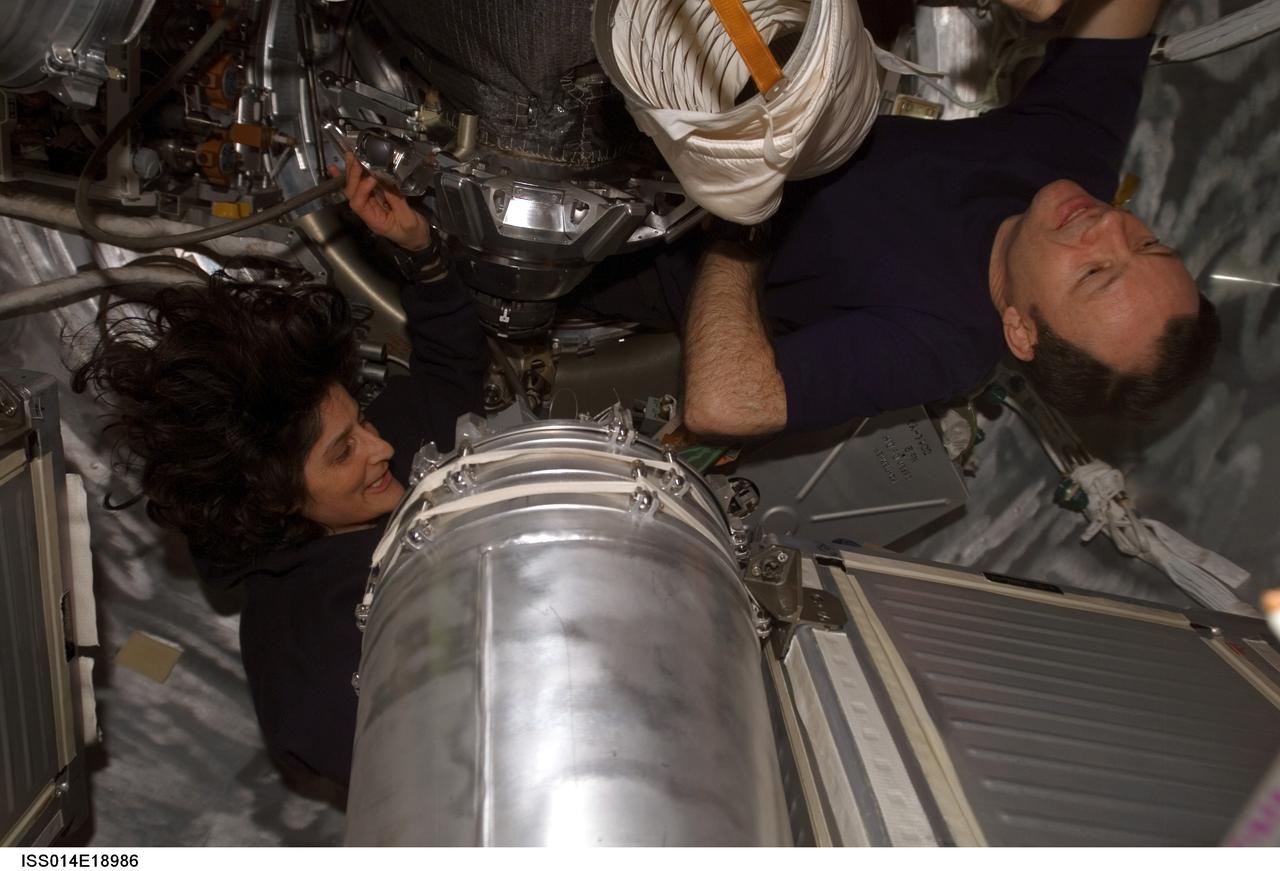
ISS014-E-18986 (5 April 2007) --- Astronauts Michael E. Lopez-Alegria (right), Expedition 14 commander and NASA space station science officer, and Sunita L. Williams, flight engineer, work with water tanks in the Progress 24 spacecraft docked to the International Space Station.
Space Launch System Corestage-2 Liquid Hydrogen(LH2) tank is under construction at NASA's Michoud Assembly Facility. Here you can see 1 of 5 barrels being loaded in the Vertical Assembly Center tool where it will be welded.
Space Launch System Corestage-2 Liquid Hydrogen(LH2) tank is under construction at NASA's Michoud Assembly Facility. Here you can see 1 of 5 barrels being loaded in the Vertical Assembly Center tool where it will be welded.
Space Launch System Corestage-2 Liquid Hydrogen(LH2) tank is under construction at NASA's Michoud Assembly Facility. Here you can see 1 of 5 barrels being loaded in the Vertical Assembly Center tool where it will be welded.
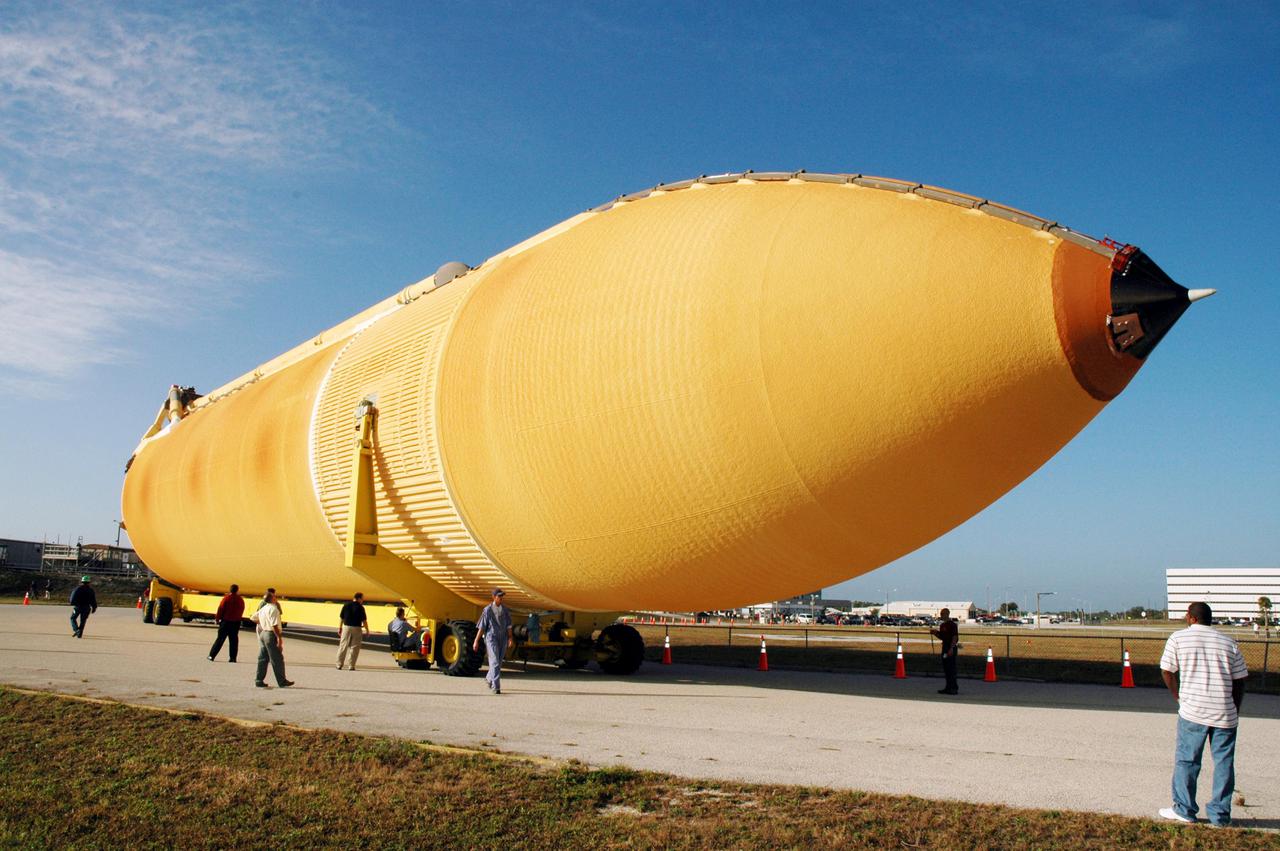
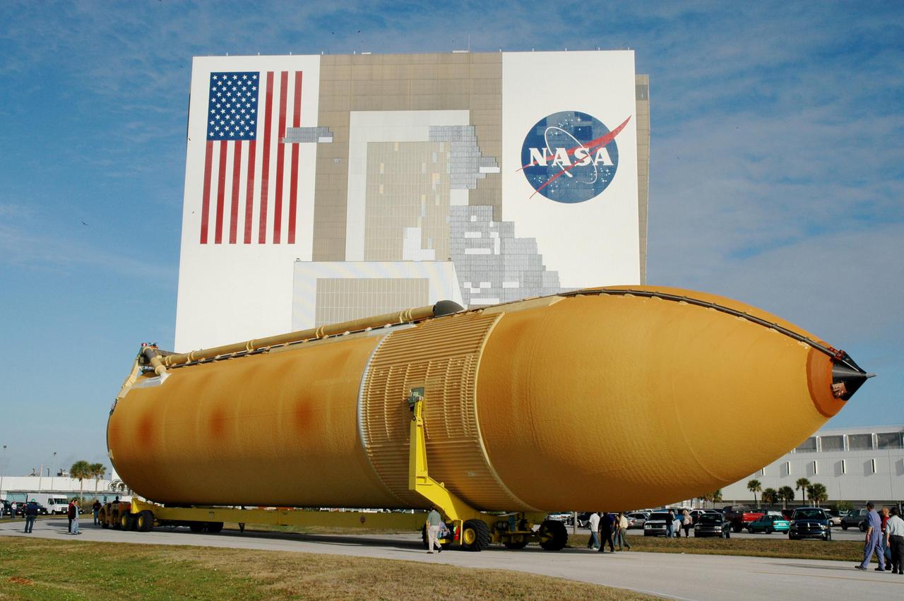
KENNEDY SPACE CENTER, FLA. - The newly redesigned External Tank turns the corner of the Launch Complex 39 Area Turn Basin parking area on its way to the Vehicle Assembly Building, seen at right. The tank arrived Jan. 5 after a 900-mile sea voyage aboard NASA’s specially designed barge, Pegasus, from the Michoud Assembly Facility in New Orleans. In the transfer aisle of the VAB, the tank will be raised from a horizontal to a vertical position, then lifted high up into a storage cell, or “checkout cell,” where it will undergo inspections of the mechanical, electrical and thermal protection systems. New processing activities resulting from re-design of the tank include inspection of the bipod heater and External Tank separation camera, which includes charging the camera batteries. The tank will be then prepared for mating to the Solid Rocket Boosters. When preparations are complete, the tank will be lifted from the checkout cell, moved across the transfer aisle and into High Bay 1, where it will be lowered and attached to the boosters, which are sitting on the Mobile Launch Platform. The tank is designated for the Return to Flight mission, STS-114, targeted for a launch opportunity beginning in May. The seven-member Discovery crew will fly to the International Space Station primarily to test and evaluate new procedures for flight safety, including Space Shuttle inspection and repair techniques.
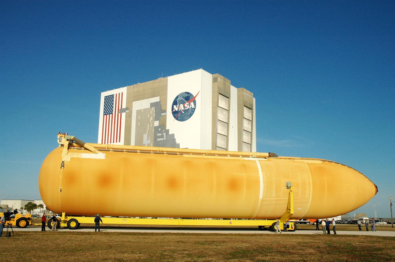
KENNEDY SPACE CENTER, FLA. - The newly redesigned External Tank wends its way through the parking area at the Launch Complex 39 Area Turn Basin on its way to the Vehicle Assembly Building, seen behind it. The tank arrived Jan. 5 after a 900-mile sea voyage aboard NASA’s specially designed barge, Pegasus, from the Michoud Assembly Facility in New Orleans. In the transfer aisle of the VAB, the tank will be raised from a horizontal to a vertical position, then lifted high up into a storage cell, or “checkout cell,” where it will undergo inspections of the mechanical, electrical and thermal protection systems. New processing activities resulting from re-design of the tank include inspection of the bipod heater and External Tank separation camera, which includes charging the camera batteries. The tank will be then prepared for mating to the Solid Rocket Boosters. When preparations are complete, the tank will be lifted from the checkout cell, moved across the transfer aisle and into High Bay 1, where it will be lowered and attached to the boosters, which are sitting on the Mobile Launch Platform. The tank is designated for the Return to Flight mission, STS-114, targeted for a launch opportunity beginning in May. The seven-member Discovery crew will fly to the International Space Station primarily to test and evaluate new procedures for flight safety, including Space Shuttle inspection and repair techniques.
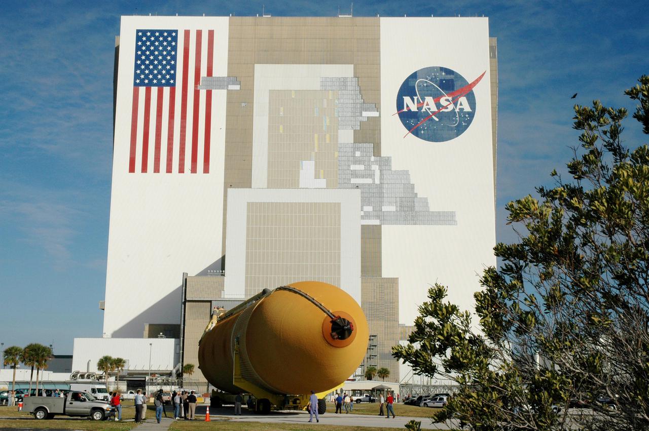
KENNEDY SPACE CENTER, FLA. - The newly redesigned External Tank heads for the open doors of the Vehicle Assembly Building, seen behind it. The tank arrived Jan. 5 after a 900-mile sea voyage aboard NASA’s specially designed barge, Pegasus, from the Michoud Assembly Facility in New Orleans. In the transfer aisle of the VAB, the tank will be raised from a horizontal to a vertical position, then lifted high up into a storage cell, or “checkout cell,” where it will undergo inspections of the mechanical, electrical and thermal protection systems. New processing activities resulting from re-design of the tank include inspection of the bipod heater and External Tank separation camera, which includes charging the camera batteries. The tank will be then prepared for mating to the Solid Rocket Boosters. When preparations are complete, the tank will be lifted from the checkout cell, moved across the transfer aisle and into High Bay 1, where it will be lowered and attached to the boosters, which are sitting on the Mobile Launch Platform. The tank is designated for the Return to Flight mission, STS-114, targeted for a launch opportunity beginning in May. The seven-member Discovery crew will fly to the International Space Station primarily to test and evaluate new procedures for flight safety, including Space Shuttle inspection and repair techniques.
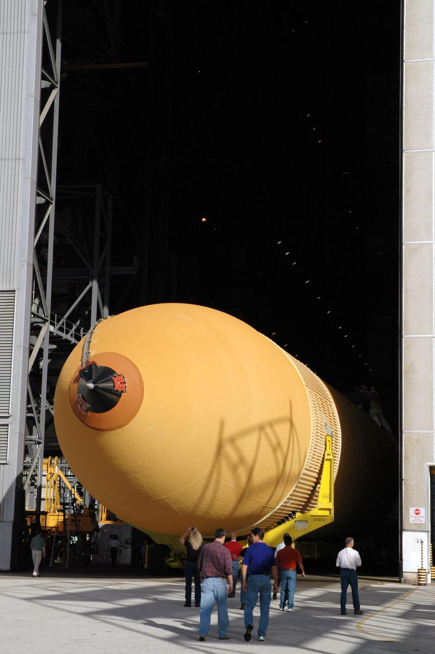
KENNEDY SPACE CENTER, FLA. - Accompanied by KSC employees, the newly redesigned External Tank rolls into the Vehicle Assembly Building. The tank arrived Jan. 5 after a 900-mile sea voyage aboard NASA’s specially designed barge, Pegasus, from the Michoud Assembly Facility in New Orleans. In the transfer aisle of the VAB, the tank will be raised from a horizontal to a vertical position, then lifted high up into a storage cell, or “checkout cell,” where it will undergo inspections of the mechanical, electrical and thermal protection systems. New processing activities resulting from re-design of the tank include inspection of the bipod heater and External Tank separation camera, which includes charging the camera batteries. The tank will be then prepared for mating to the Solid Rocket Boosters. When preparations are complete, the tank will be lifted from the checkout cell, moved across the transfer aisle and into High Bay 1, where it will be lowered and attached to the boosters, which are sitting on the Mobile Launch Platform. The tank is designated for the Return to Flight mission, STS-114, targeted for a launch opportunity beginning in May. The seven-member Discovery crew will fly to the International Space Station primarily to test and evaluate new procedures for flight safety, including Space Shuttle inspection and repair techniques.
KENNEDY SPACE CENTER, FLA. - The newly redesigned External Tank is slowly moved from the dock in the Launch Complex 39 Area Turn Basin on its way to the Vehicle Assembly Building, seen at left. The tank arrived Jan. 5 after a 900-mile sea voyage aboard NASA’s specially designed barge, Pegasus, from the Michoud Assembly Facility in New Orleans. In the transfer aisle of the VAB, the tank will be raised from a horizontal to a vertical position, then lifted high up into a storage cell, or “checkout cell,” where it will undergo inspections of the mechanical, electrical and thermal protection systems. New processing activities resulting from re-design of the tank include inspection of the bipod heater and External Tank separation camera, which includes charging the camera batteries. The tank will be then prepared for mating to the Solid Rocket Boosters. When preparations are complete, the tank will be lifted from the checkout cell, moved across the transfer aisle and into High Bay 1, where it will be lowered and attached to the boosters, which are sitting on the Mobile Launch Platform. The tank is designated for the Return to Flight mission, STS-114, targeted for a launch opportunity beginning in May. The seven-member Discovery crew will fly to the International Space Station primarily to test and evaluate new procedures for flight safety, including Space Shuttle inspection and repair techniques.
KENNEDY SPACE CENTER, FLA. - The newly redesigned External Tank turns the corner of the Launch Complex 39 Area Turn Basin parking area on its way to the Vehicle Assembly Building, seen at right. The tank arrived Jan. 5 after a 900-mile sea voyage aboard NASA’s specially designed barge, Pegasus, from the Michoud Assembly Facility in New Orleans. In the transfer aisle of the VAB, the tank will be raised from a horizontal to a vertical position, then lifted high up into a storage cell, or “checkout cell,” where it will undergo inspections of the mechanical, electrical and thermal protection systems. New processing activities resulting from re-design of the tank include inspection of the bipod heater and External Tank separation camera, which includes charging the camera batteries. The tank will be then prepared for mating to the Solid Rocket Boosters. When preparations are complete, the tank will be lifted from the checkout cell, moved across the transfer aisle and into High Bay 1, where it will be lowered and attached to the boosters, which are sitting on the Mobile Launch Platform. The tank is designated for the Return to Flight mission, STS-114, targeted for a launch opportunity beginning in May. The seven-member Discovery crew will fly to the International Space Station primarily to test and evaluate new procedures for flight safety, including Space Shuttle inspection and repair techniques.
KENNEDY SPACE CENTER, FLA. - The newly redesigned External Tank slowly moves toward the Vehicle Assembly Building, seen at right. The tank arrived Jan. 5 after a 900-mile sea voyage aboard NASA’s specially designed barge, Pegasus, from the Michoud Assembly Facility in New Orleans. In the transfer aisle of the VAB, the tank will be raised from a horizontal to a vertical position, then lifted high up into a storage cell, or “checkout cell,” where it will undergo inspections of the mechanical, electrical and thermal protection systems. New processing activities resulting from re-design of the tank include inspection of the bipod heater and External Tank separation camera, which includes charging the camera batteries. The tank will be then prepared for mating to the Solid Rocket Boosters. When preparations are complete, the tank will be lifted from the checkout cell, moved across the transfer aisle and into High Bay 1, where it will be lowered and attached to the boosters, which are sitting on the Mobile Launch Platform. The tank is designated for the Return to Flight mission, STS-114, targeted for a launch opportunity beginning in May. The seven-member Discovery crew will fly to the International Space Station primarily to test and evaluate new procedures for flight safety, including Space Shuttle inspection and repair techniques.
KENNEDY SPACE CENTER, FLA. - The newly redesigned External Tank moves closer to its destination, the Vehicle Assembly Building, seen behind it. The tank arrived Jan. 5 after a 900-mile sea voyage aboard NASA’s specially designed barge, Pegasus, from the Michoud Assembly Facility in New Orleans. In the transfer aisle of the VAB, the tank will be raised from a horizontal to a vertical position, then lifted high up into a storage cell, or “checkout cell,” where it will undergo inspections of the mechanical, electrical and thermal protection systems. New processing activities resulting from re-design of the tank include inspection of the bipod heater and External Tank separation camera, which includes charging the camera batteries. The tank will be then prepared for mating to the Solid Rocket Boosters. When preparations are complete, the tank will be lifted from the checkout cell, moved across the transfer aisle and into High Bay 1, where it will be lowered and attached to the boosters, which are sitting on the Mobile Launch Platform. The tank is designated for the Return to Flight mission, STS-114, targeted for a launch opportunity beginning in May. The seven-member Discovery crew will fly to the International Space Station primarily to test and evaluate new procedures for flight safety, including Space Shuttle inspection and repair techniques.
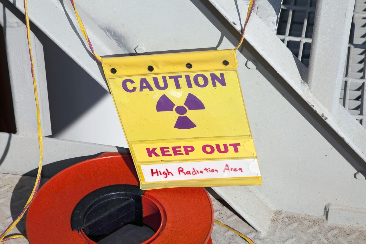
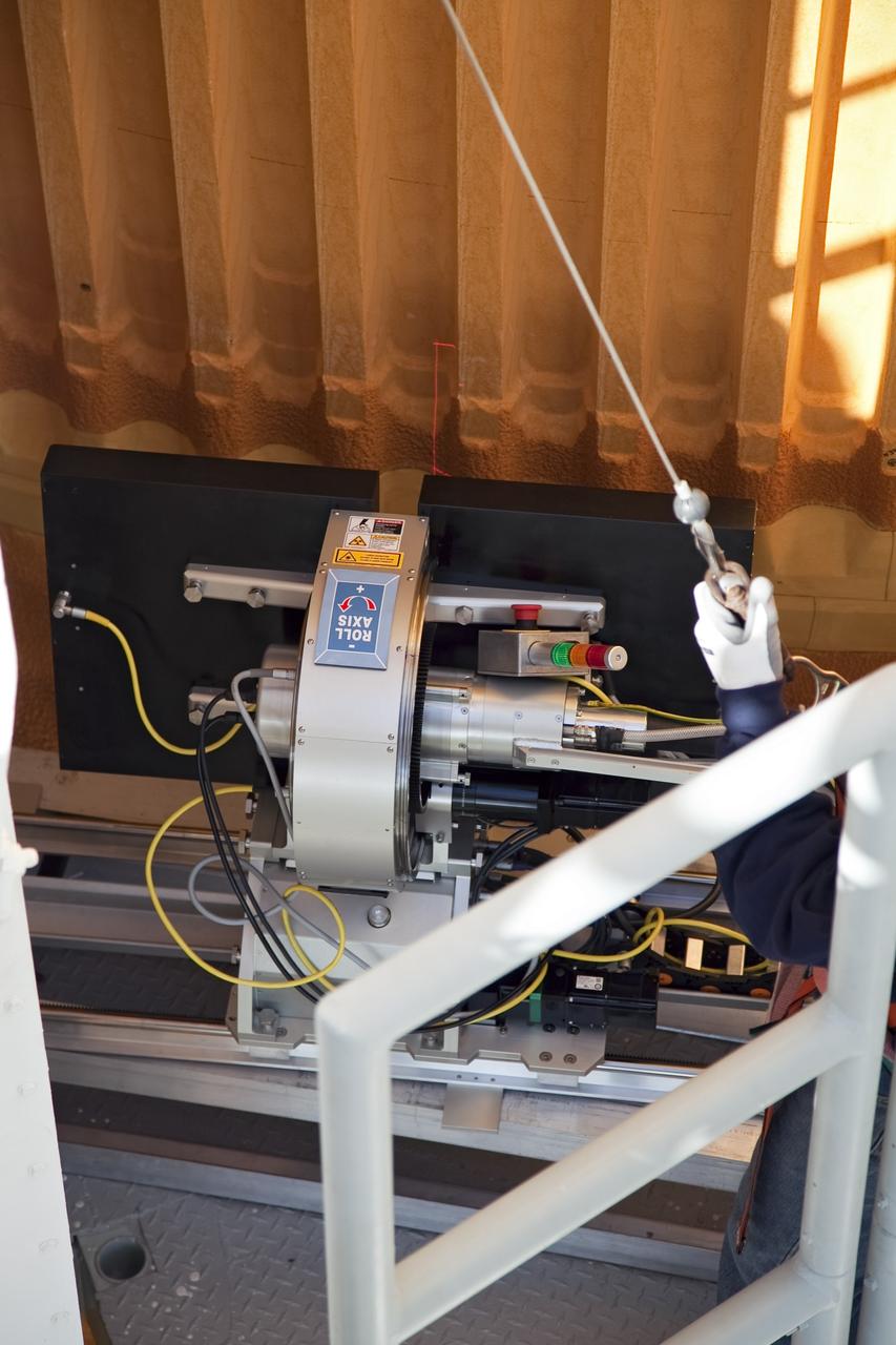
CAPE CANAVERAL, Fla. -- An engineer uses a backscatter device to examine space shuttle Discovery's external fuel tank on Launch Pad 39A at NASA's Kennedy Space Center in Florida. The device bounces radiation off the tank, allowing technicians to see under the tank's foam insulation. The foam cracked during initial loading operations for Discovery’s STS-133 launch attempt on Nov. 5, and technicians later identified two cracked stringers, which are the composite aluminum ribs located vertically on the tank’s intertank area. Those two stringers have been replaced and reinforced with doublers, which are shaped metal pieces twice as thick as the original stringers. Launch is no earlier than Dec. 17 at 8:51 p.m. EST. For more information on STS-133, visit www.nasa.gov/mission_pages/shuttle/shuttlemissions/sts133/. Photo credit: NASA/Frank Michaux
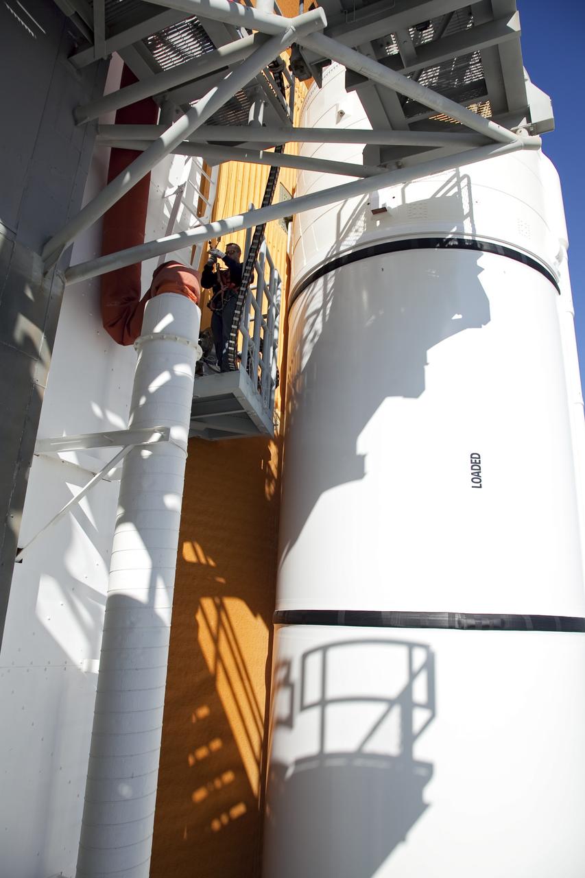
CAPE CANAVERAL, Fla. -- An engineer uses a backscatter device to examine space shuttle Discovery's external fuel tank on Launch Pad 39A at NASA's Kennedy Space Center in Florida. The device bounces radiation off the tank, allowing technicians to see under the tank's foam insulation. The foam cracked during initial loading operations for Discovery’s STS-133 launch attempt on Nov. 5, and technicians later identified two cracked stringers, which are the composite aluminum ribs located vertically on the tank’s intertank area. Those two stringers have been replaced and reinforced with doublers, which are shaped metal pieces twice as thick as the original stringers. Launch is no earlier than Dec. 17 at 8:51 p.m. EST. For more information on STS-133, visit www.nasa.gov/mission_pages/shuttle/shuttlemissions/sts133/. Photo credit: NASA/Frank Michaux
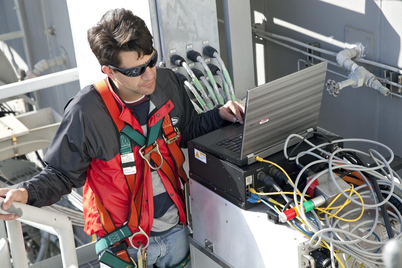
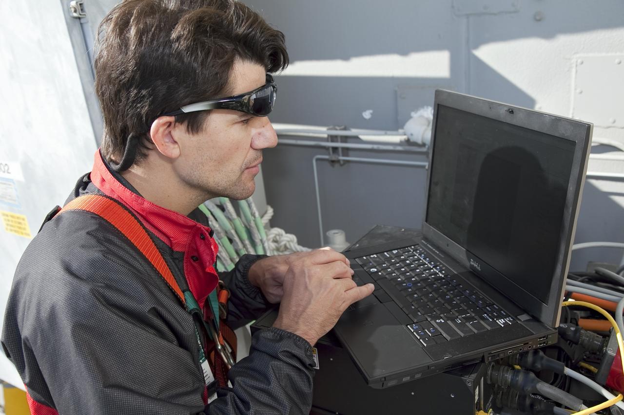
CAPE CANAVERAL, Fla. -- An engineer examines images of space shuttle Discovery's external fuel tank taken from a backscatter device on Launch Pad 39A at NASA's Kennedy Space Center in Florida. The device bounces radiation off the tank, allowing technicians to see under the tank's foam insulation. The foam cracked during initial loading operations for Discovery’s STS-133 launch attempt on Nov. 5, and technicians later identified two cracked stringers, which are the composite aluminum ribs located vertically on the tank’s intertank area. Those two stringers have been replaced and reinforced with doublers, which are shaped metal pieces twice as thick as the original stringers. Launch is no earlier than Dec. 17 at 8:51 p.m. EST. For more information on STS-133, visit www.nasa.gov/mission_pages/shuttle/shuttlemissions/sts133/. Photo credit: NASA/Frank Michaux

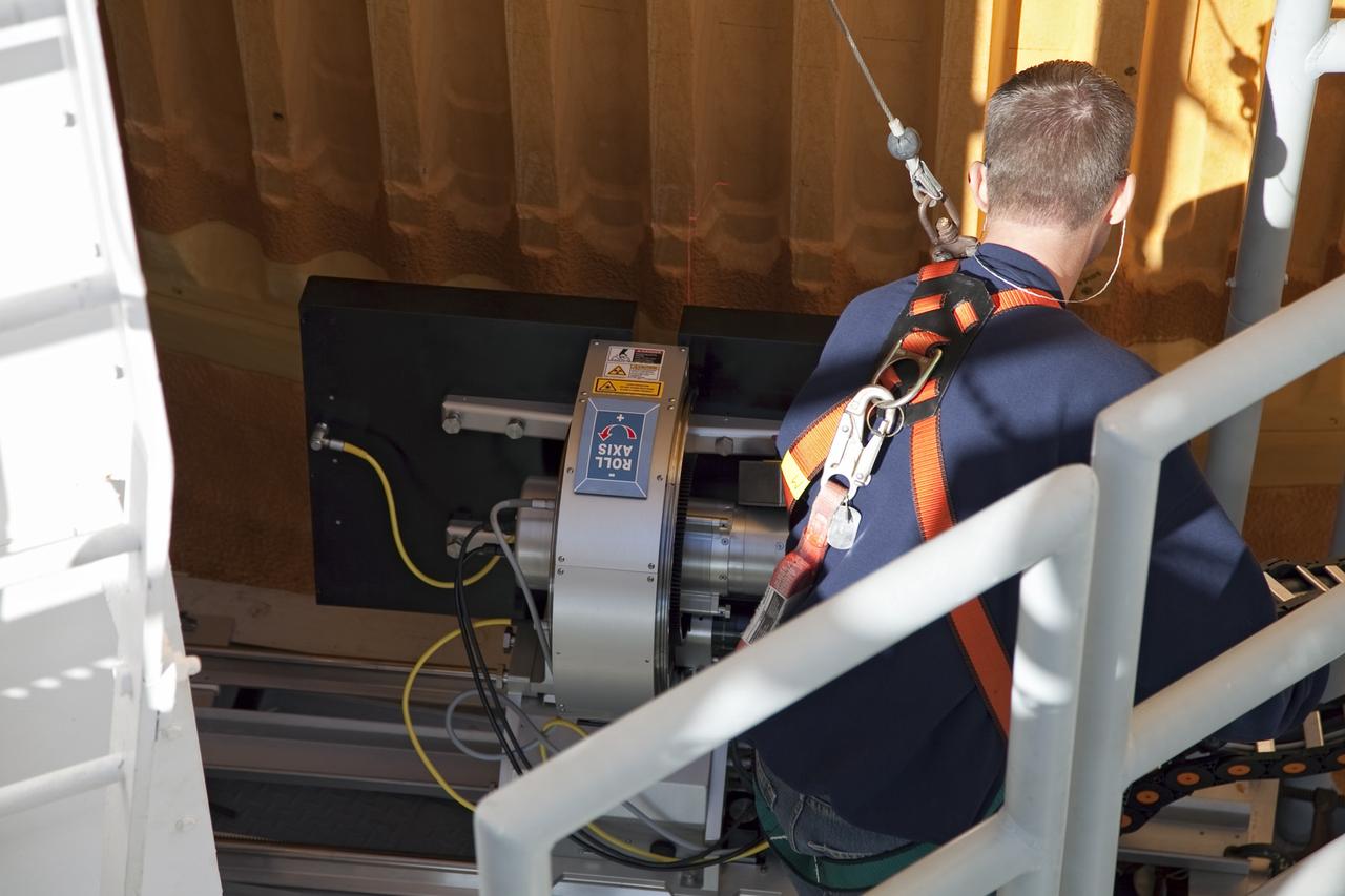
CAPE CANAVERAL, Fla. -- A backscatter device is being used to examine space shuttle Discovery's external fuel tank on Launch Pad 39A at NASA's Kennedy Space Center in Florida. The device bounces radiation off the tank, allowing technicians to see under the tank's foam insulation. The foam cracked during initial loading operations for Discovery’s STS-133 launch attempt on Nov. 5, and technicians later identified two cracked stringers, which are the composite aluminum ribs located vertically on the tank’s intertank area. Those two stringers have been replaced and reinforced with doublers, which are shaped metal pieces twice as thick as the original stringers. Launch is no earlier than Dec. 17 at 8:51 p.m. EST. For more information on STS-133, visit www.nasa.gov/mission_pages/shuttle/shuttlemissions/sts133/. Photo credit: NASA/Frank Michaux
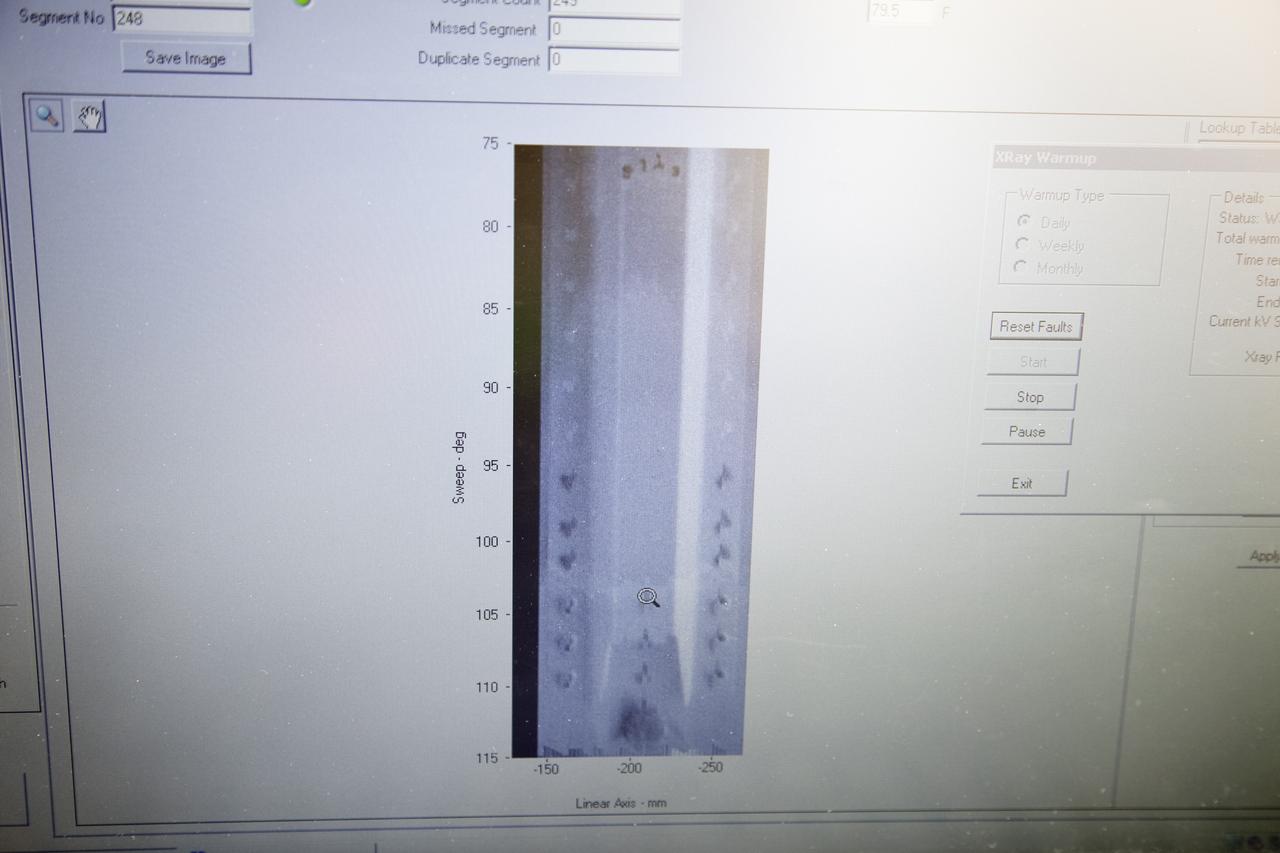
CAPE CANAVERAL, Fla. -- An engineer examines images of space shuttle Discovery's external fuel tank taken from a backscatter device on Launch Pad 39A at NASA's Kennedy Space Center in Florida. The device bounces radiation off the tank, allowing technicians to see under the tank's foam insulation. The foam cracked during initial loading operations for Discovery’s STS-133 launch attempt on Nov. 5, and technicians later identified two cracked stringers, which are the composite aluminum ribs located vertically on the tank’s intertank area. Those two stringers have been replaced and reinforced with doublers, which are shaped metal pieces twice as thick as the original stringers. Launch is no earlier than Dec. 17 at 8:51 p.m. EST. For more information on STS-133, visit www.nasa.gov/mission_pages/shuttle/shuttlemissions/sts133/. Photo credit: NASA/Frank Michaux
CAPE CANAVERAL, Fla. -- An engineer uses a backscatter device to examine space shuttle Discovery's external fuel tank on Launch Pad 39A at NASA's Kennedy Space Center in Florida. The device bounces radiation off the tank, allowing technicians to see under the tank's foam insulation. The foam cracked during initial loading operations for Discovery’s STS-133 launch attempt on Nov. 5, and technicians later identified two cracked stringers, which are the composite aluminum ribs located vertically on the tank’s intertank area. Those two stringers have been replaced and reinforced with doublers, which are shaped metal pieces twice as thick as the original stringers. Launch is no earlier than Dec. 17 at 8:51 p.m. EST. For more information on STS-133, visit www.nasa.gov/mission_pages/shuttle/shuttlemissions/sts133/. Photo credit: NASA/Frank Michaux
CAPE CANAVERAL, Fla. -- A backscatter device is being used to examine space shuttle Discovery's external fuel tank on Launch Pad 39A at NASA's Kennedy Space Center in Florida. The device bounces radiation off the tank, allowing technicians to see under the tank's foam insulation. The foam cracked during initial loading operations for Discovery’s STS-133 launch attempt on Nov. 5, and technicians later identified two cracked stringers, which are the composite aluminum ribs located vertically on the tank’s intertank area. Those two stringers have been replaced and reinforced with doublers, which are shaped metal pieces twice as thick as the original stringers. Launch is no earlier than Dec. 17 at 8:51 p.m. EST. For more information on STS-133, visit www.nasa.gov/mission_pages/shuttle/shuttlemissions/sts133/. Photo credit: NASA/Frank Michaux
CAPE CANAVERAL, Fla. -- An engineer uses a backscatter device to examine space shuttle Discovery's external fuel tank on Launch Pad 39A at NASA's Kennedy Space Center in Florida. The device bounces radiation off the tank, allowing technicians to see under the tank's foam insulation. The foam cracked during initial loading operations for Discovery’s STS-133 launch attempt on Nov. 5, and technicians later identified two cracked stringers, which are the composite aluminum ribs located vertically on the tank’s intertank area. Those two stringers have been replaced and reinforced with doublers, which are shaped metal pieces twice as thick as the original stringers. Launch is no earlier than Dec. 17 at 8:51 p.m. EST. For more information on STS-133, visit www.nasa.gov/mission_pages/shuttle/shuttlemissions/sts133/. Photo credit: NASA/Frank Michaux
CAPE CANAVERAL, Fla. -- Engineers will use a backscatter device to examine space shuttle Discovery's external fuel tank on Launch Pad 39A at NASA's Kennedy Space Center in Florida. The device bounces radiation off the tank, allowing technicians to see under the tank's foam insulation. The foam cracked during initial loading operations for Discovery’s STS-133 launch attempt on Nov. 5, and technicians later identified two cracked stringers, which are the composite aluminum ribs located vertically on the tank’s intertank area. Those two stringers have been replaced and reinforced with doublers, which are shaped metal pieces twice as thick as the original stringers. Launch is no earlier than Dec. 17 at 8:51 p.m. EST. For more information on STS-133, visit www.nasa.gov/mission_pages/shuttle/shuttlemissions/sts133/. Photo credit: NASA/Frank Michaux
CAPE CANAVERAL, Fla. -- An engineer examines images of space shuttle Discovery's external fuel tank taken from a backscatter device on Launch Pad 39A at NASA's Kennedy Space Center in Florida. The device bounces radiation off the tank, allowing technicians to see under the tank's foam insulation. The foam cracked during initial loading operations for Discovery’s STS-133 launch attempt on Nov. 5, and technicians later identified two cracked stringers, which are the composite aluminum ribs located vertically on the tank’s intertank area. Those two stringers have been replaced and reinforced with doublers, which are shaped metal pieces twice as thick as the original stringers. Launch is no earlier than Dec. 17 at 8:51 p.m. EST. For more information on STS-133, visit www.nasa.gov/mission_pages/shuttle/shuttlemissions/sts133/. Photo credit: NASA/Frank Michaux
CAPE CANAVERAL, Fla. -- An engineer uses a backscatter device to examine space shuttle Discovery's external fuel tank on Launch Pad 39A at NASA's Kennedy Space Center in Florida. The device bounces radiation off the tank, allowing technicians to see under the tank's foam insulation. The foam cracked during initial loading operations for Discovery’s STS-133 launch attempt on Nov. 5, and technicians later identified two cracked stringers, which are the composite aluminum ribs located vertically on the tank’s intertank area. Those two stringers have been replaced and reinforced with doublers, which are shaped metal pieces twice as thick as the original stringers. Launch is no earlier than Dec. 17 at 8:51 p.m. EST. For more information on STS-133, visit www.nasa.gov/mission_pages/shuttle/shuttlemissions/sts133/. Photo credit: NASA/Frank Michaux
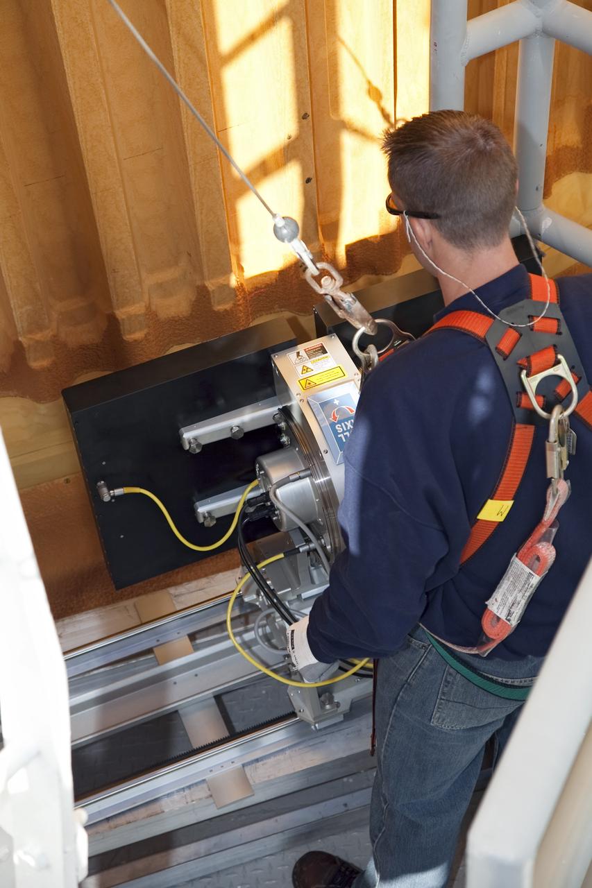
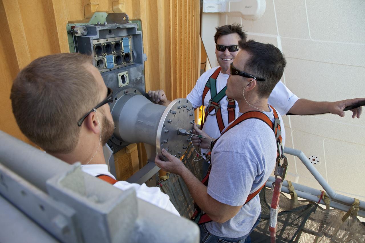
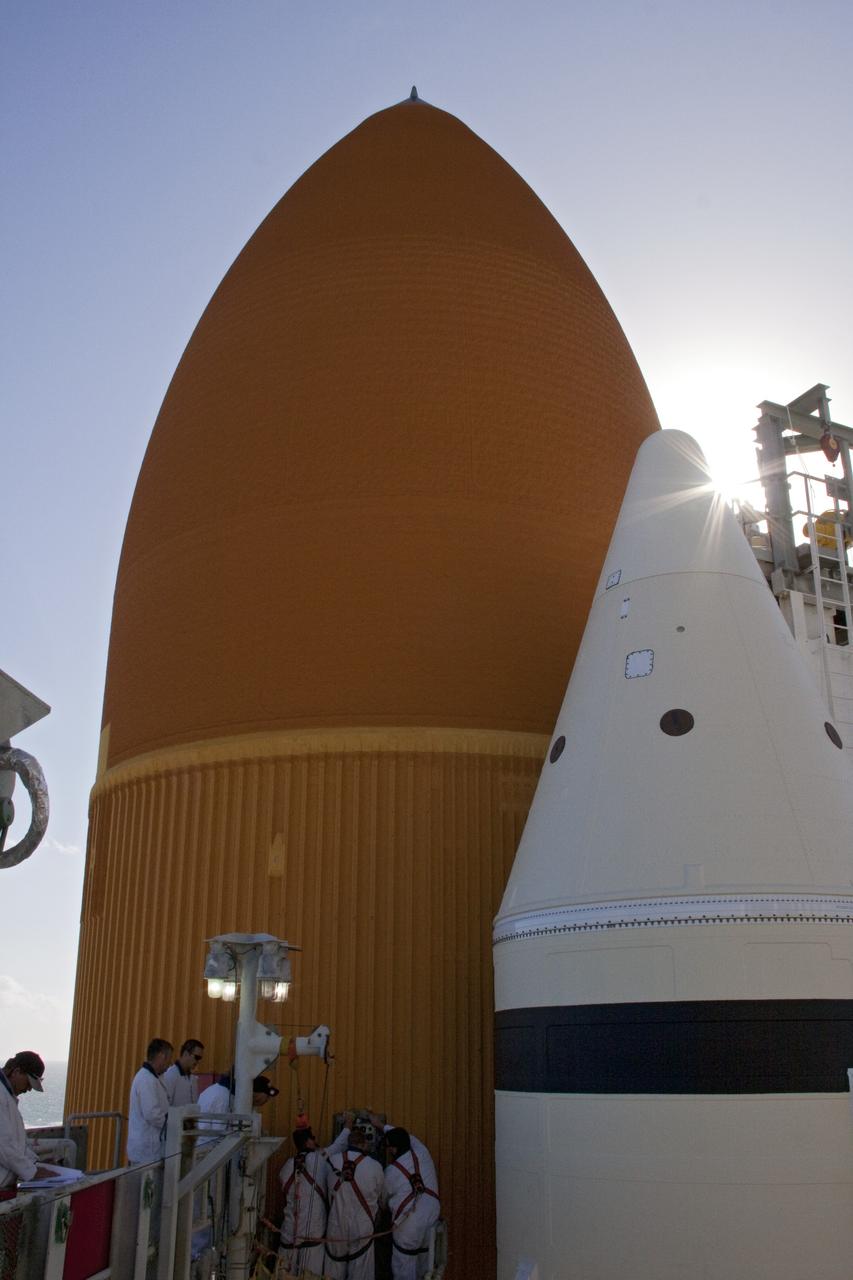
CAPE CANAVERAL, Fla. -- On Launch Pad 39A at NASA's Kennedy Space Center in Florida, technicians reattach the vent line to the ground umbilical carrier plate (GUCP) on space shuttle Discovery's external fuel tank. A hydrogen gas leak at that location during tanking for Discovery's STS-133 mission to the International Space Station caused the launch attempt to be scrubbed Nov. 5. The GUCP is the overboard vent to the pad and the flame stack where the excess hydrogen is burned off. Discovery's next launch attempt is no earlier than Nov. 30 at 4:02 a.m. EST. For more information on STS-133, visit www.nasa.gov/mission_pages/shuttle/shuttlemissions/sts133/. Photo credit: NASA/Ben Smegelsky
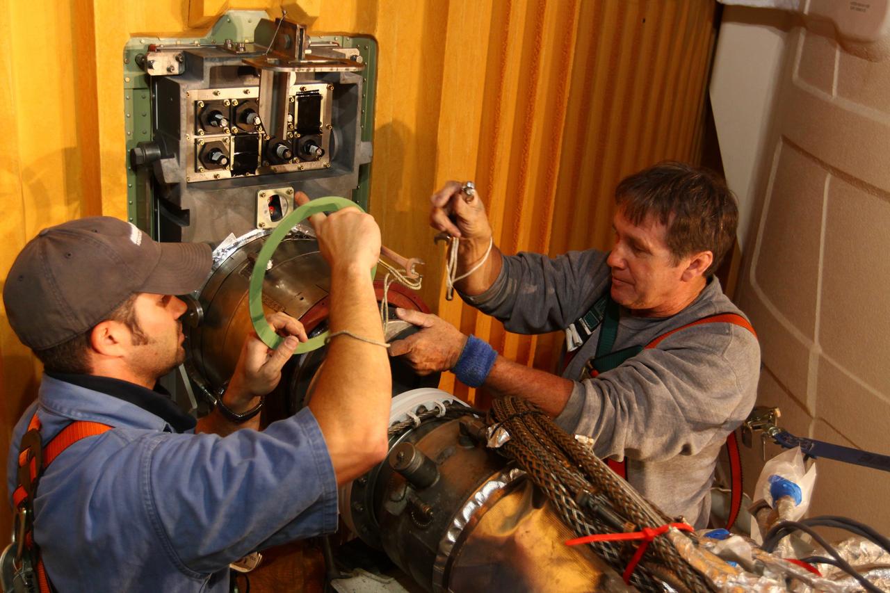
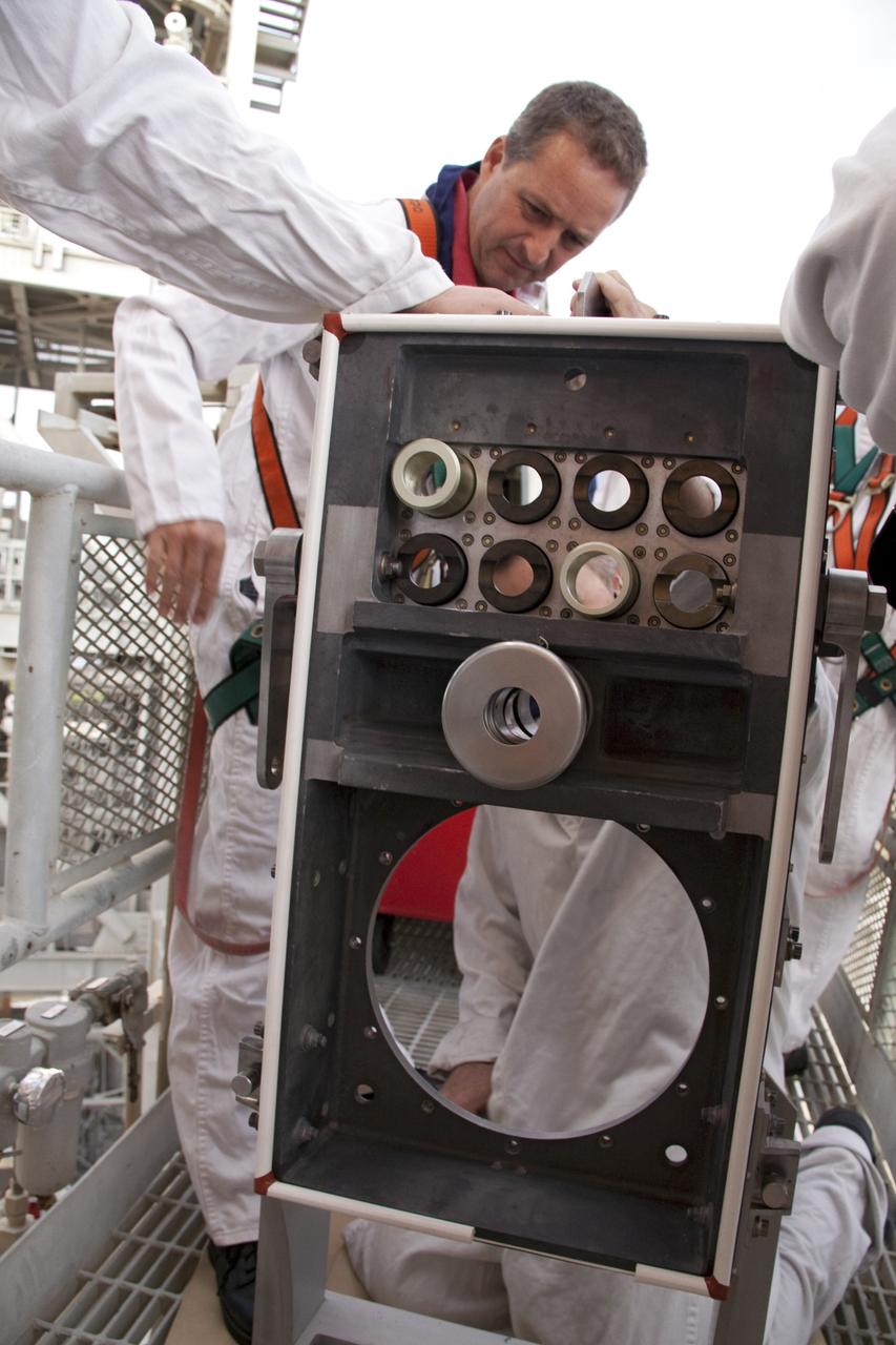
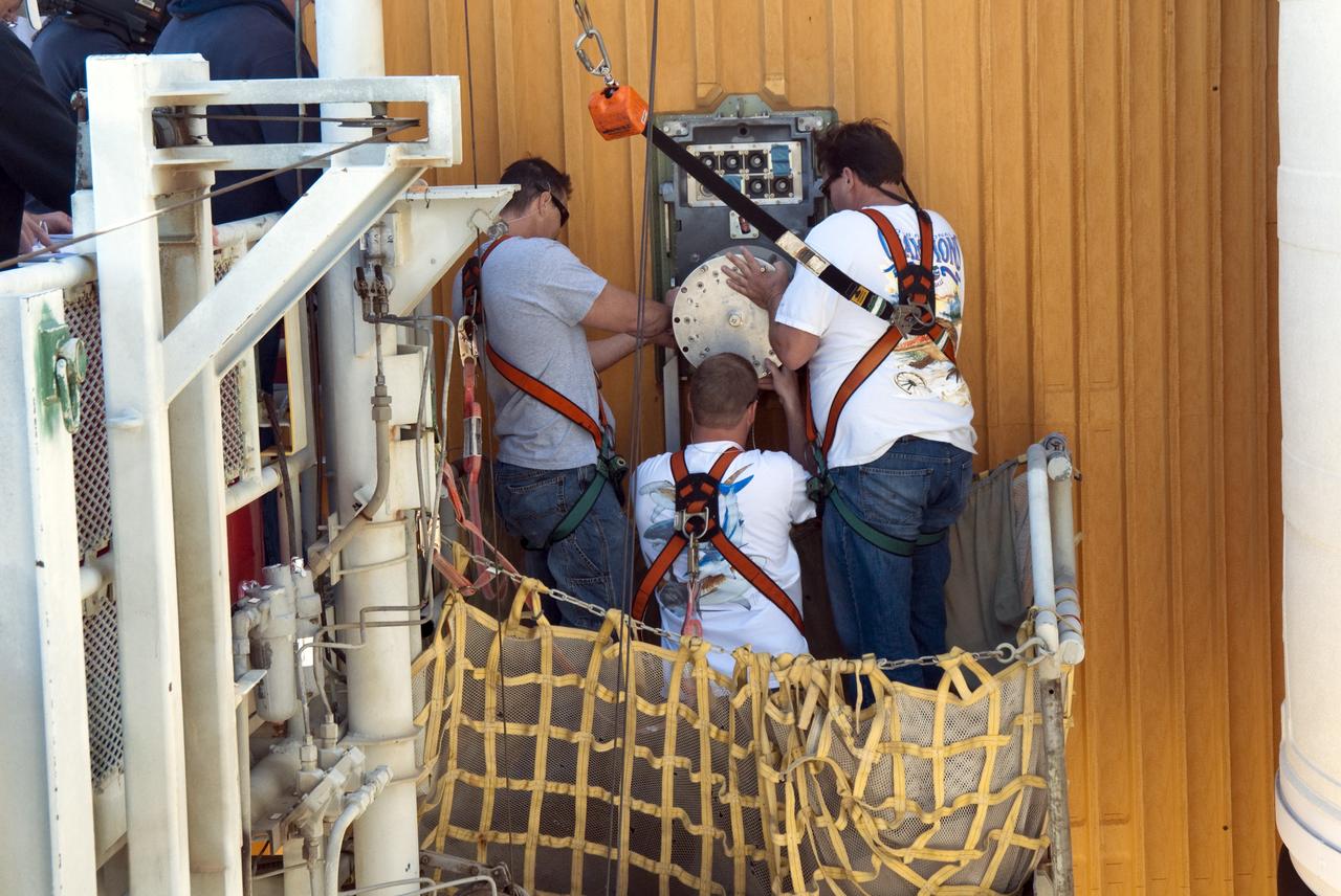
CAPE CANAVERAL, Fla. -- On Launch Pad 39A at NASA's Kennedy Space Center in Florida, workers begin to remove the ground umbilical carrier plate (GUCP) from space shuttle Discovery's external fuel tank. A hydrogen gas leak at that location during tanking for Discovery's STS-133 mission to the International Space Station caused the launch attempt to be scrubbed Nov. 5. The GUCP will be examined to determine the cause of the hydrogen leak and then repaired. The GUCP is the overboard vent to the pad and the flame stack where the excess hydrogen is burned off. For more information on STS-133, visit www.nasa.gov/mission_pages/shuttle/shuttlemissions/sts133/. Photo credit: NASA/Dimitri Gerondidakis

CAPE CANAVERAL, Fla. -- On Launch Pad 39A at NASA's Kennedy Space Center in Florida, workers begin to remove the seal from the ground umbilical carrier plate (GUCP). A hydrogen gas leak at that location on the external fuel tank during tanking for space shuttle Discovery's STS-133 mission to the International Space Station caused the launch attempt to be scrubbed Nov. 5. The GUCP will be examined to determine the cause of the hydrogen leak and then repaired. The GUCP is the overboard vent to the pad and the flame stack where the excess hydrogen is burned off. For more information on STS-133, visit www.nasa.gov/mission_pages/shuttle/shuttlemissions/sts133/. Photo credit: NASA/Jack Pfaller
CAPE CANAVERAL, Fla. -- On Launch Pad 39A at NASA's Kennedy Space Center in Florida, workers prepare to install this new 7-inch quick disconnect on the ground umbilical carrier plate (GUCP) of space shuttle Discovery's external fuel tank. A hydrogen gas leak at that location during tanking for Discovery's STS-133 mission to the International Space Station caused the launch attempt to be scrubbed Nov. 5. The GUCP is the overboard vent to the pad and the flame stack where the excess hydrogen is burned off. For more information on STS-133, visit www.nasa.gov/mission_pages/shuttle/shuttlemissions/sts133/. Photo credit: NASA/Charisse Nahser
CAPE CANAVERAL, Fla. -- On Launch Pad 39A at NASA's Kennedy Space Center in Florida, workers install a new 7-inch quick disconnect on the ground umbilical carrier plate (GUCP) of space shuttle Discovery's external fuel tank. A hydrogen gas leak at that location during tanking for Discovery's STS-133 mission to the International Space Station caused the launch attempt to be scrubbed Nov. 5. The GUCP is the overboard vent to the pad and the flame stack where the excess hydrogen is burned off. For more information on STS-133, visit www.nasa.gov/mission_pages/shuttle/shuttlemissions/sts133/. Photo credit: NASA/Frankie Martin
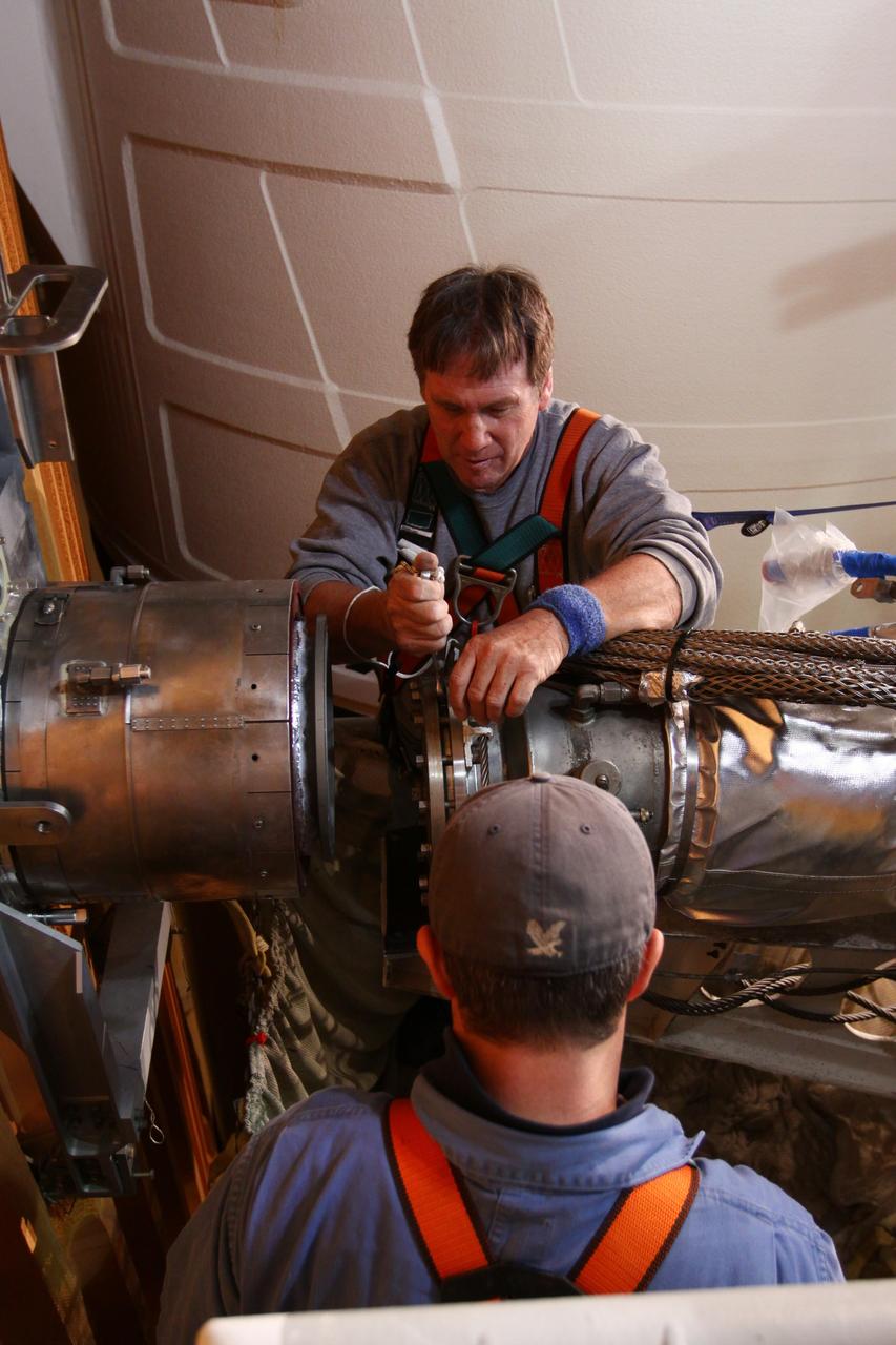
CAPE CANAVERAL, Fla. -- On Launch Pad 39A at NASA's Kennedy Space Center in Florida, technicians reattach the vent line to the ground umbilical carrier plate (GUCP) on space shuttle Discovery's external fuel tank. A hydrogen gas leak at that location during tanking for Discovery's STS-133 mission to the International Space Station caused the launch attempt to be scrubbed Nov. 5. The GUCP is the overboard vent to the pad and the flame stack where the excess hydrogen is burned off. Discovery's next launch attempt is no earlier than Nov. 30 at 4:02 a.m. EST. For more information on STS-133, visit www.nasa.gov/mission_pages/shuttle/shuttlemissions/sts133/. Photo credit: NASA/Ben Smegelsky
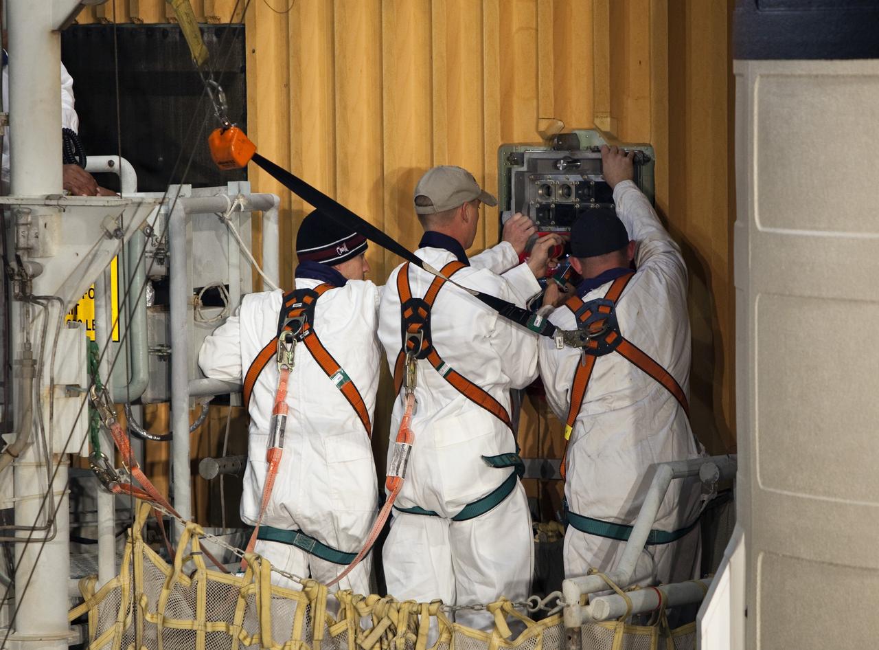
CAPE CANAVERAL, Fla. -- On Launch Pad 39A at NASA's Kennedy Space Center in Florida, workers prepare to install a new ground umbilical carrier plate (GUCP) on space shuttle Discovery's external fuel tank. A hydrogen gas leak at that location during tanking for Discovery's STS-133 mission to the International Space Station caused the launch attempt to be scrubbed Nov. 5. The GUCP is the overboard vent to the pad and the flame stack where the excess hydrogen is burned off. For more information on STS-133, visit www.nasa.gov/mission_pages/shuttle/shuttlemissions/sts133/. Photo credit: NASA/Troy Cryder
CAPE CANAVERAL, Fla. -- On Launch Pad 39A at NASA's Kennedy Space Center in Florida, workers begin to install a new ground umbilical carrier plate (GUCP) on space shuttle Discovery's external fuel tank. A hydrogen gas leak at that location during tanking for Discovery's STS-133 mission to the International Space Station caused the launch attempt to be scrubbed Nov. 5. The GUCP is the overboard vent to the pad and the flame stack where the excess hydrogen is burned off. For more information on STS-133, visit www.nasa.gov/mission_pages/shuttle/shuttlemissions/sts133/. Photo credit: NASA/Troy Cryder
CAPE CANAVERAL, Fla. -- On Launch Pad 39A at NASA's Kennedy Space Center in Florida, workers begin to install a new ground umbilical carrier plate (GUCP) on space shuttle Discovery's external fuel tank. A hydrogen gas leak at that location during tanking for Discovery's STS-133 mission to the International Space Station caused the launch attempt to be scrubbed Nov. 5. The GUCP is the overboard vent to the pad and the flame stack where the excess hydrogen is burned off. For more information on STS-133, visit www.nasa.gov/mission_pages/shuttle/shuttlemissions/sts133/. Photo credit: NASA/Troy Cryder

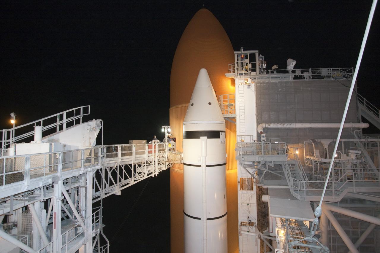
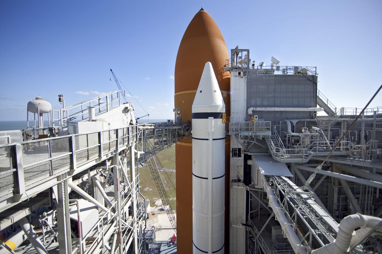
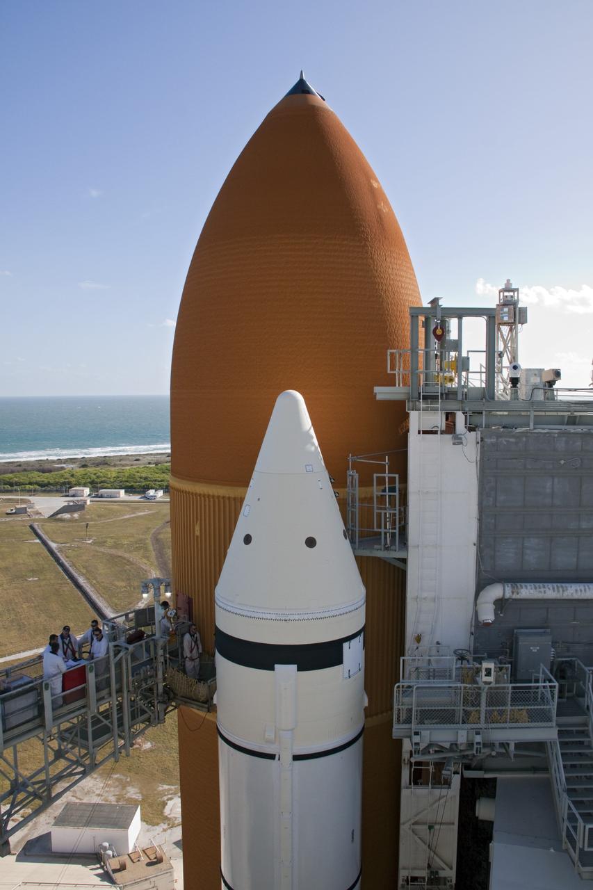
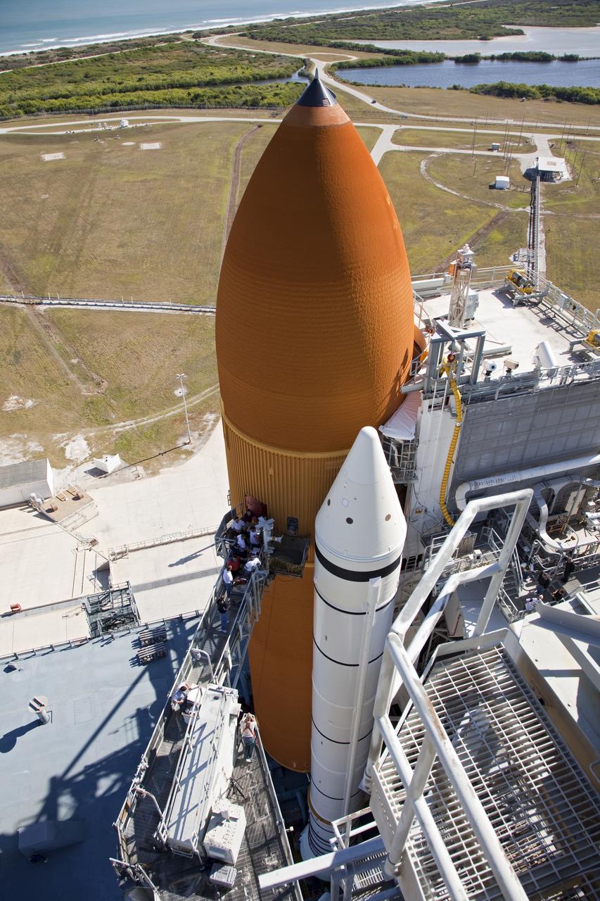
CAPE CANAVERAL, Fla. -- On Launch Pad 39A at NASA's Kennedy Space Center in Florida, workers will focus their attention on the ground umbilical carrier plate (GUCP), which is on space shuttle Discovery's orange external fuel tank at the end of the access arm. A hydrogen gas leak at that location during tanking for Discovery's STS-133 mission to the International Space Station caused the launch attempt to be scrubbed Nov. 5. The GUCP will be examined to determine the cause of the hydrogen leak and then repaired. The GUCP is the overboard vent to the pad and the flame stack where the excess hydrogen is burned off. For more information on STS-133, visit www.nasa.gov/mission_pages/shuttle/shuttlemissions/sts133/. Photo credit: NASA/Jack Pfaller
CAPE CANAVERAL, Fla. -- On Launch Pad 39A at NASA's Kennedy Space Center in Florida, technicians reattach the vent line to the ground umbilical carrier plate (GUCP) on space shuttle Discovery's external fuel tank. A hydrogen gas leak at that location during tanking for Discovery's STS-133 mission to the International Space Station caused the launch attempt to be scrubbed Nov. 5. The GUCP is the overboard vent to the pad and the flame stack where the excess hydrogen is burned off. Discovery's next launch attempt is no earlier than Nov. 30 at 4:02 a.m. EST. For more information on STS-133, visit www.nasa.gov/mission_pages/shuttle/shuttlemissions/sts133/. Photo credit: NASA/Ben Smegelsky
CAPE CANAVERAL, Fla. -- On Launch Pad 39A at NASA's Kennedy Space Center in Florida, technicians reattach the vent line to the ground umbilical carrier plate (GUCP) on space shuttle Discovery's external fuel tank. A hydrogen gas leak at that location during tanking for Discovery's STS-133 mission to the International Space Station caused the launch attempt to be scrubbed Nov. 5. The GUCP is the overboard vent to the pad and the flame stack where the excess hydrogen is burned off. Discovery's next launch attempt is no earlier than Nov. 30 at 4:02 a.m. EST. For more information on STS-133, visit www.nasa.gov/mission_pages/shuttle/shuttlemissions/sts133/. Photo credit: NASA/Ben Smegelsky
CAPE CANAVERAL, Fla. -- On Launch Pad 39A at NASA's Kennedy Space Center in Florida, technicians reattach the vent line to the ground umbilical carrier plate (GUCP) on space shuttle Discovery's external fuel tank. A hydrogen gas leak at that location during tanking for Discovery's STS-133 mission to the International Space Station caused the launch attempt to be scrubbed Nov. 5. The GUCP is the overboard vent to the pad and the flame stack where the excess hydrogen is burned off. Discovery's next launch attempt is no earlier than Nov. 30 at 4:02 a.m. EST. For more information on STS-133, visit www.nasa.gov/mission_pages/shuttle/shuttlemissions/sts133/. Photo credit: NASA/Ben Smegelsky
CAPE CANAVERAL, Fla. -- On Launch Pad 39A at NASA's Kennedy Space Center in Florida, workers install a new 7-inch quick disconnect on the ground umbilical carrier plate (GUCP) of space shuttle Discovery's external fuel tank. A hydrogen gas leak at that location during tanking for Discovery's STS-133 mission to the International Space Station caused the launch attempt to be scrubbed Nov. 5. The GUCP is the overboard vent to the pad and the flame stack where the excess hydrogen is burned off. For more information on STS-133, visit www.nasa.gov/mission_pages/shuttle/shuttlemissions/sts133/. Photo credit: NASA/Frankie Martin
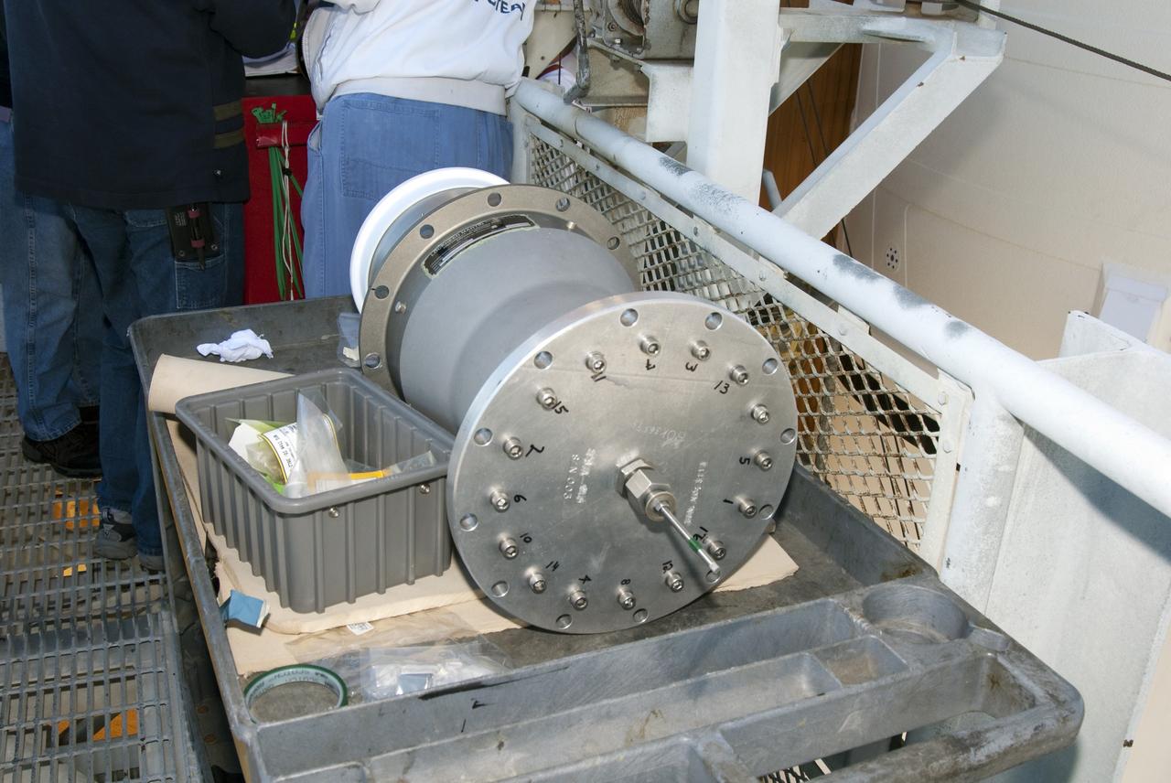
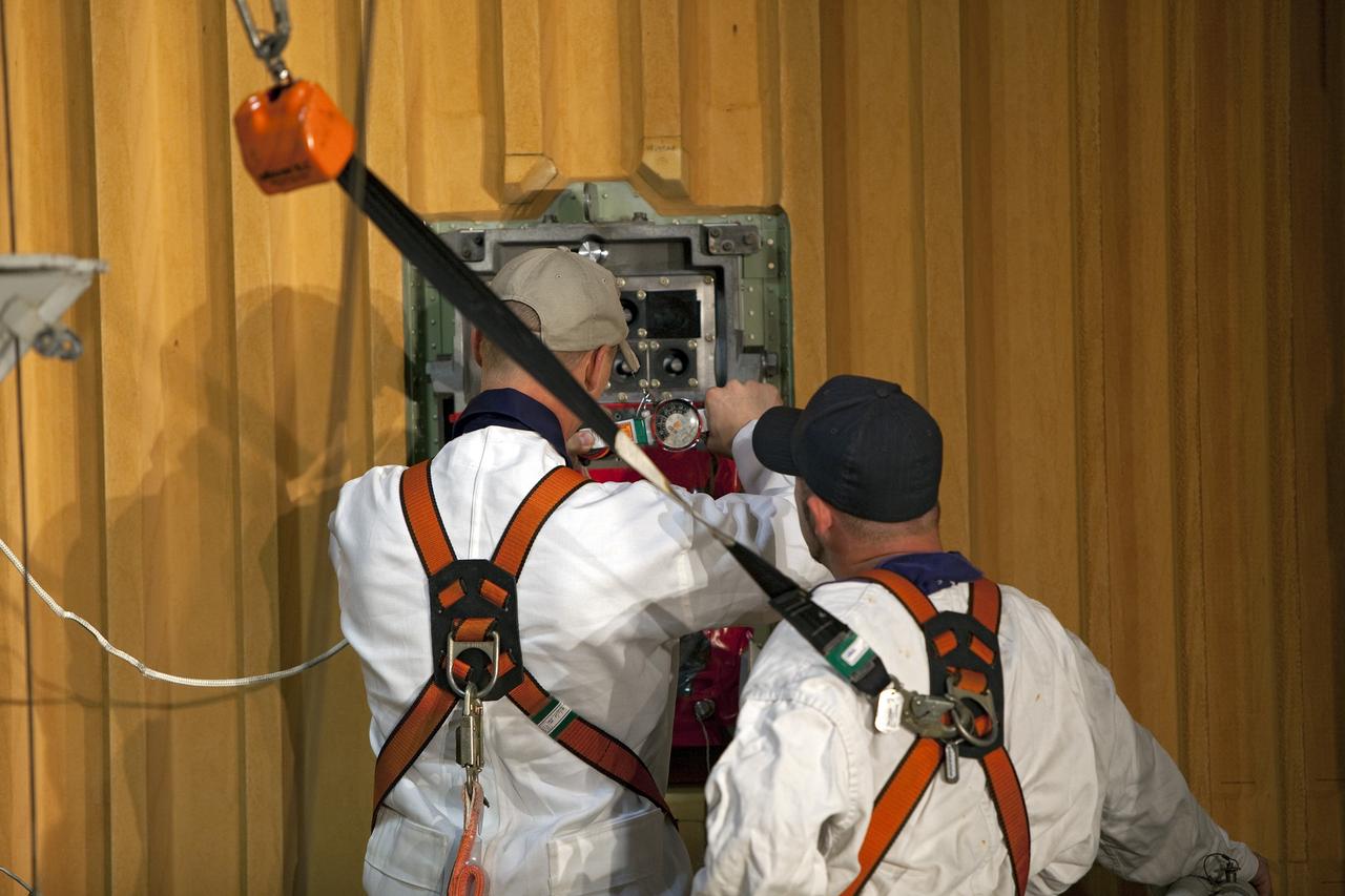
CAPE CANAVERAL, Fla. -- On Launch Pad 39A at NASA's Kennedy Space Center in Florida, the ground umbilical carrier plate (GUCP) is ready to be examined. A hydrogen gas leak at that location on the external fuel tank during tanking for space shuttle Discovery's STS-133 mission to the International Space Station caused the launch attempt to be scrubbed Nov. 5. The GUCP will be examined to determine the cause of the hydrogen leak and then repaired. The GUCP is the overboard vent to the pad and the flame stack where the excess hydrogen is burned off. For more information on STS-133, visit www.nasa.gov/mission_pages/shuttle/shuttlemissions/sts133/. Photo credit: NASA/Dimitri Gerondidakis

CAPE CANAVERAL, Fla. -- On Launch Pad 39A at NASA's Kennedy Space Center in Florida, technicians reattach the vent line to the ground umbilical carrier plate (GUCP) on space shuttle Discovery's external fuel tank. A hydrogen gas leak at that location during tanking for Discovery's STS-133 mission to the International Space Station caused the launch attempt to be scrubbed Nov. 5. The GUCP is the overboard vent to the pad and the flame stack where the excess hydrogen is burned off. Discovery's next launch attempt is no earlier than Nov. 30 at 4:02 a.m. EST. For more information on STS-133, visit www.nasa.gov/mission_pages/shuttle/shuttlemissions/sts133/. Photo credit: NASA/Ben Smegelsky

CAPE CANAVERAL, Fla. -- On Launch Pad 39A at NASA's Kennedy Space Center in Florida, workers install a new 7-inch quick disconnect on the ground umbilical carrier plate (GUCP) of space shuttle Discovery's external fuel tank. A hydrogen gas leak at that location during tanking for Discovery's STS-133 mission to the International Space Station caused the launch attempt to be scrubbed Nov. 5. The GUCP is the overboard vent to the pad and the flame stack where the excess hydrogen is burned off. For more information on STS-133, visit www.nasa.gov/mission_pages/shuttle/shuttlemissions/sts133/. Photo credit: NASA/Charisse Nahser
CAPE CANAVERAL, Fla. -- On Launch Pad 39A at NASA's Kennedy Space Center in Florida, a new 7-inch quick disconnect is installed on the ground umbilical carrier plate (GUCP) of space shuttle Discovery's external fuel tank. A hydrogen gas leak at that location during tanking for Discovery's STS-133 mission to the International Space Station caused the launch attempt to be scrubbed Nov. 5. The GUCP is the overboard vent to the pad and the flame stack where the excess hydrogen is burned off. For more information on STS-133, visit www.nasa.gov/mission_pages/shuttle/shuttlemissions/sts133/. Photo credit: NASA/Frankie Martin

CAPE CANAVERAL, Fla. -- On Launch Pad 39A at NASA's Kennedy Space Center in Florida, technicians reattach the vent line to the ground umbilical carrier plate (GUCP) on space shuttle Discovery's external fuel tank. A hydrogen gas leak at that location during tanking for Discovery's STS-133 mission to the International Space Station caused the launch attempt to be scrubbed Nov. 5. The GUCP is the overboard vent to the pad and the flame stack where the excess hydrogen is burned off. Discovery's next launch attempt is no earlier than Nov. 30 at 4:02 a.m. EST. For more information on STS-133, visit www.nasa.gov/mission_pages/shuttle/shuttlemissions/sts133/. Photo credit: NASA/Ben Smegelsky
CAPE CANAVERAL, Fla. -- On Launch Pad 39A at NASA's Kennedy Space Center in Florida, workers examine the ground umbilical carrier plate (GUCP). A hydrogen gas leak at that location on the external fuel tank during tanking for space shuttle Discovery's STS-133 mission to the International Space Station caused the launch attempt to be scrubbed Nov. 5. The GUCP will be examined to determine the cause of the hydrogen leak and then repaired. The GUCP is the overboard vent to the pad and the flame stack where the excess hydrogen is burned off. For more information on STS-133, visit www.nasa.gov/mission_pages/shuttle/shuttlemissions/sts133/. Photo credit: NASA/Dimitri Gerondidakis
CAPE CANAVERAL, Fla. -- On Launch Pad 39A at NASA's Kennedy Space Center in Florida, workers begin to install a new ground umbilical carrier plate (GUCP) on space shuttle Discovery's external fuel tank. A hydrogen gas leak at that location during tanking for Discovery's STS-133 mission to the International Space Station caused the launch attempt to be scrubbed Nov. 5. The GUCP is the overboard vent to the pad and the flame stack where the excess hydrogen is burned off. For more information on STS-133, visit www.nasa.gov/mission_pages/shuttle/shuttlemissions/sts133/. Photo credit: NASA/Troy Cryder
CAPE CANAVERAL, Fla. -- On Launch Pad 39A at NASA's Kennedy Space Center in Florida, workers install a new 7-inch quick disconnect on the ground umbilical carrier plate (GUCP) of space shuttle Discovery's external fuel tank. A hydrogen gas leak at that location during tanking for Discovery's STS-133 mission to the International Space Station caused the launch attempt to be scrubbed Nov. 5. The GUCP is the overboard vent to the pad and the flame stack where the excess hydrogen is burned off. For more information on STS-133, visit www.nasa.gov/mission_pages/shuttle/shuttlemissions/sts133/. Photo credit: NASA/Charisse Nahser
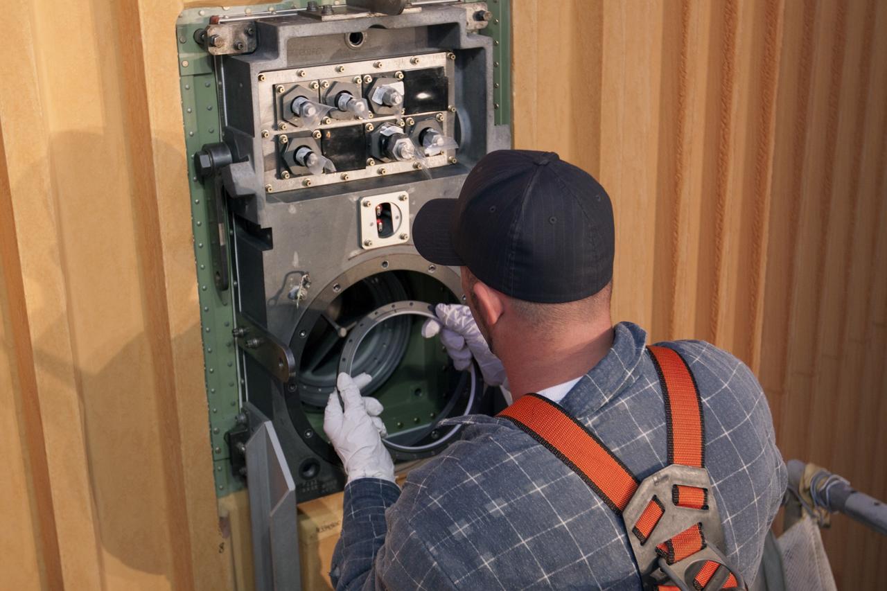
CAPE CANAVERAL, Fla. -- On Launch Pad 39A at NASA's Kennedy Space Center in Florida, workers remove the seal from the ground umbilical carrier plate (GUCP). A hydrogen gas leak at that location on the external fuel tank during tanking for space shuttle Discovery's STS-133 mission to the International Space Station caused the launch attempt to be scrubbed Nov. 5. The GUCP will be examined to determine the cause of the hydrogen leak and then repaired. The GUCP is the overboard vent to the pad and the flame stack where the excess hydrogen is burned off. For more information on STS-133, visit www.nasa.gov/mission_pages/shuttle/shuttlemissions/sts133/. Photo credit: NASA/Jack Pfaller
CAPE CANAVERAL, Fla. -- On Launch Pad 39A at NASA's Kennedy Space Center in Florida, workers prepare to remove the ground umbilical carrier plate (GUCP) from space shuttle Discovery's external fuel tank. A hydrogen gas leak at that location during tanking for Discovery's STS-133 mission to the International Space Station caused the launch attempt to be scrubbed Nov. 5. The GUCP will be examined to determine the cause of the hydrogen leak and then repaired. The GUCP is the overboard vent to the pad and the flame stack where the excess hydrogen is burned off. For more information on STS-133, visit www.nasa.gov/mission_pages/shuttle/shuttlemissions/sts133/. Photo credit: NASA/Dimitri Gerondidakis
CAPE CANAVERAL, Fla. -- On Launch Pad 39A at NASA's Kennedy Space Center in Florida, workers begin to install a new ground umbilical carrier plate (GUCP) on space shuttle Discovery's external fuel tank. A hydrogen gas leak at that location during tanking for Discovery's STS-133 mission to the International Space Station caused the launch attempt to be scrubbed Nov. 5. The GUCP is the overboard vent to the pad and the flame stack where the excess hydrogen is burned off. For more information on STS-133, visit www.nasa.gov/mission_pages/shuttle/shuttlemissions/sts133/. Photo credit: NASA/Troy Cryder
CAPE CANAVERAL, Fla. -- On Launch Pad 39A at NASA's Kennedy Space Center in Florida, workers install a new 7-inch quick disconnect on the ground umbilical carrier plate (GUCP) of space shuttle Discovery's external fuel tank. A hydrogen gas leak at that location during tanking for Discovery's STS-133 mission to the International Space Station caused the launch attempt to be scrubbed Nov. 5. The GUCP is the overboard vent to the pad and the flame stack where the excess hydrogen is burned off. For more information on STS-133, visit www.nasa.gov/mission_pages/shuttle/shuttlemissions/sts133/. Photo credit: NASA/Frankie Martin
CAPE CANAVERAL, Fla. -- On Launch Pad 39A at NASA's Kennedy Space Center in Florida, workers examine the seal from the ground umbilical carrier plate (GUCP). A hydrogen gas leak at that location on the external fuel tank during tanking for space shuttle Discovery's STS-133 mission to the International Space Station caused the launch attempt to be scrubbed Nov. 5. The GUCP will be examined to determine the cause of the hydrogen leak and then repaired. The GUCP is the overboard vent to the pad and the flame stack where the excess hydrogen is burned off. For more information on STS-133, visit www.nasa.gov/mission_pages/shuttle/shuttlemissions/sts133/. Photo credit: NASA/Jack Pfaller
CAPE CANAVERAL, Fla. -- On Launch Pad 39A at NASA's Kennedy Space Center in Florida, technicians reattach the vent line to the ground umbilical carrier plate (GUCP) on space shuttle Discovery's external fuel tank. A hydrogen gas leak at that location during tanking for Discovery's STS-133 mission to the International Space Station caused the launch attempt to be scrubbed Nov. 5. The GUCP is the overboard vent to the pad and the flame stack where the excess hydrogen is burned off. Discovery's next launch attempt is no earlier than Nov. 30 at 4:02 a.m. EST. For more information on STS-133, visit www.nasa.gov/mission_pages/shuttle/shuttlemissions/sts133/. Photo credit: NASA/Ben Smegelsky