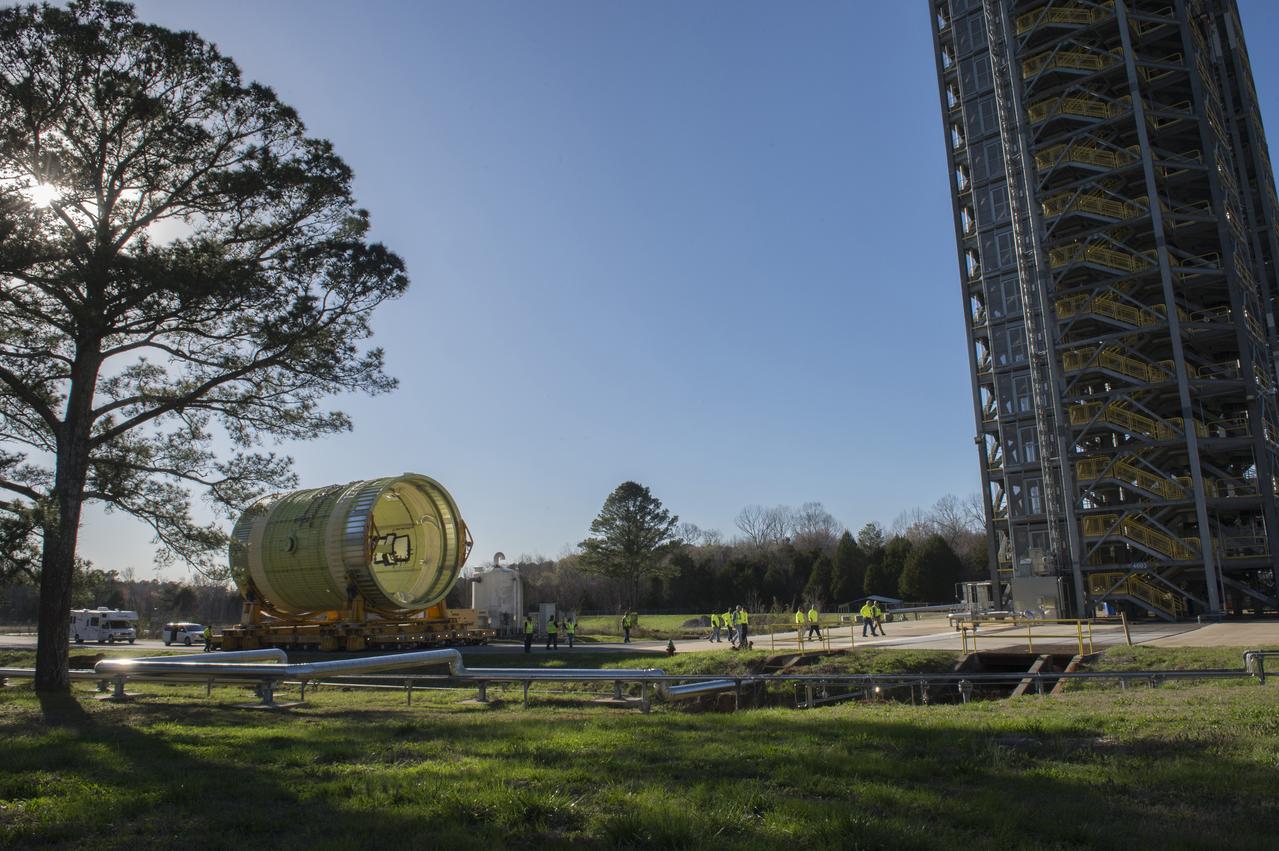
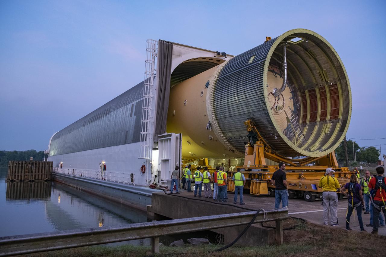
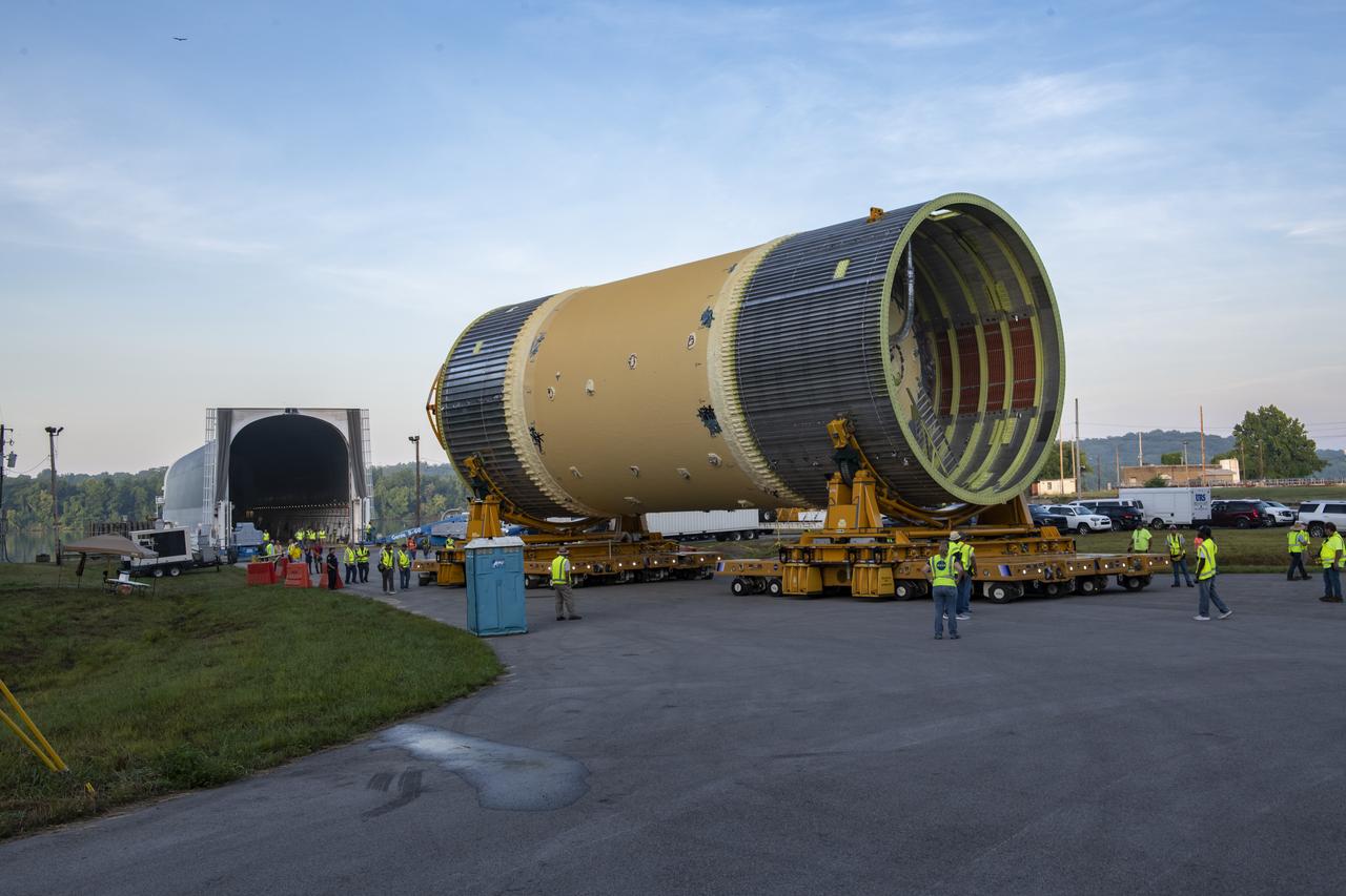
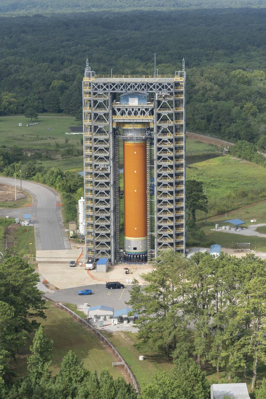
The SLS Stages Intertank Structural Test Assembly (STA) is rolling off the NASA Pegasus Barge at the MSFC Dock enroute to the MSFC 4619 Load Test Annex test facility for qualification testing via MSFC West Test Area. STA approaches Test Stand 4693, SLS LH2 test Stand, on way to Bldg. 4619
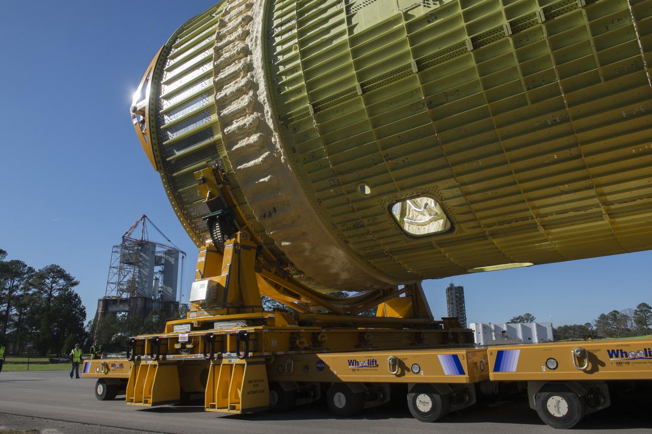
The SLS Stages Intertank Structural Test Assembly (STA) is rolling off the NASA Pegasus Barge at the MSFC Dock enroute to the MSFC 4619 Load Test Annex test facility for qualification testing via MSFC West Test Area. Historic Saturn 1-C test stand on far left, blockhouse 4670 on far right, SLS LH2 test stand, 4693, in center.
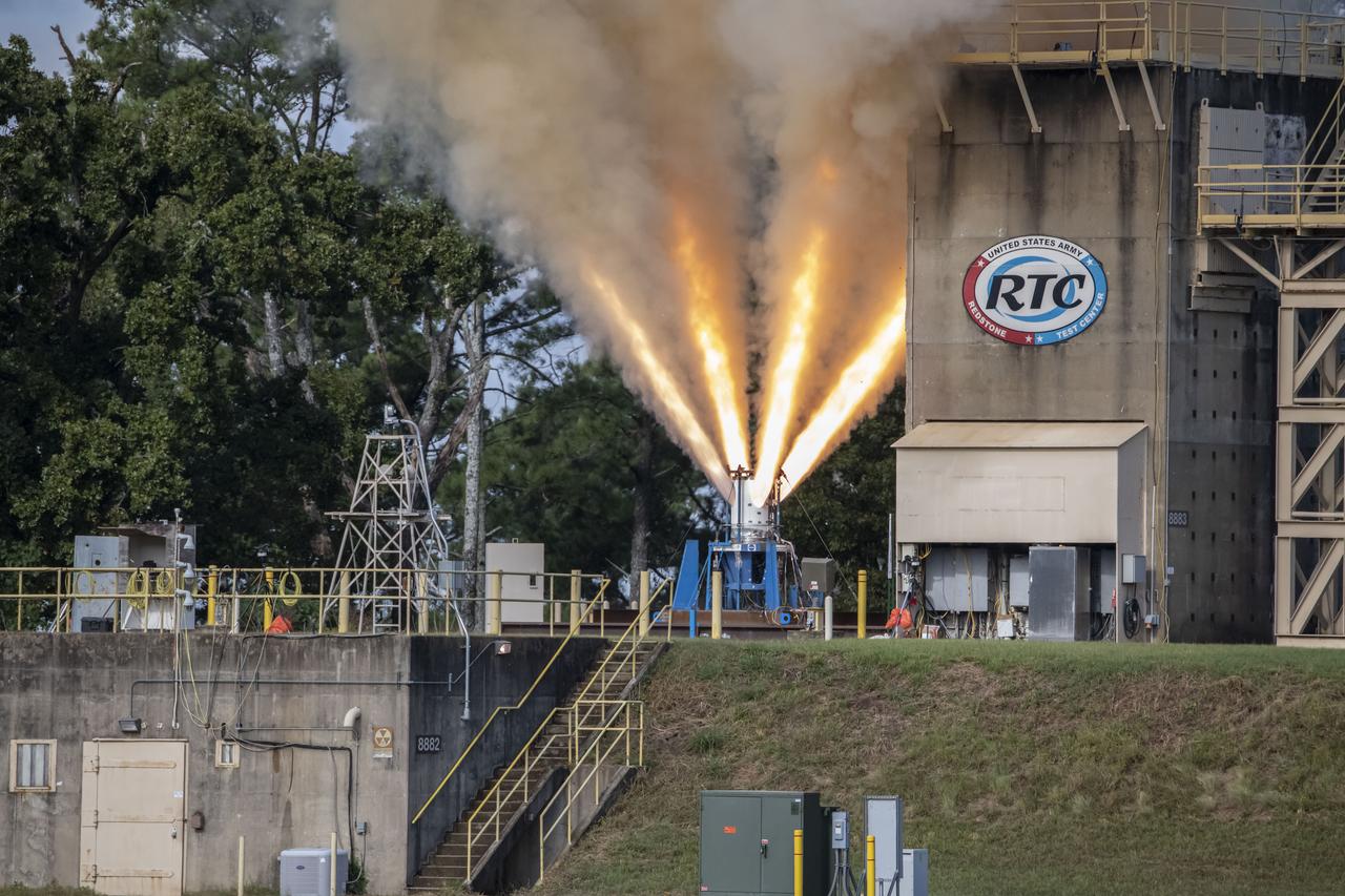
Redstone Test Center hosted the final hot fire test of the Aerojet Rocketdyne Orion Launch Abort System (LAS) at Redstone Arsenal’s test area 5.
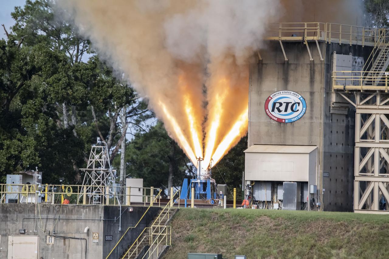
Redstone Test Center hosted the final hot fire test of the Aerojet Rocketdyne Orion Launch Abort System (LAS) at Redstone Arsenal’s test area 5.
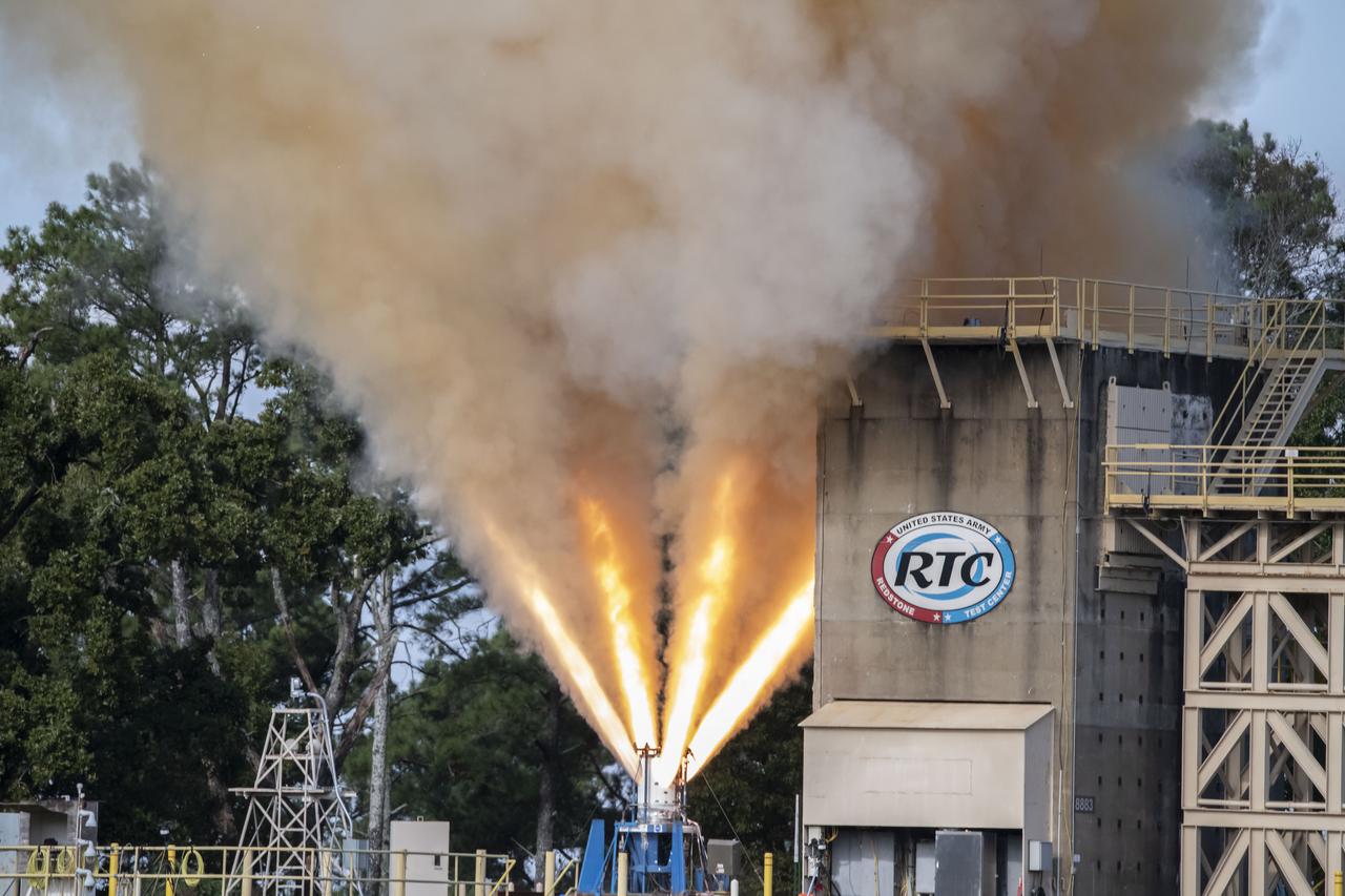
Redstone Test Center hosted the final hot fire test of the Aerojet Rocketdyne Orion Launch Abort System (LAS) at Redstone Arsenal’s test area 5.
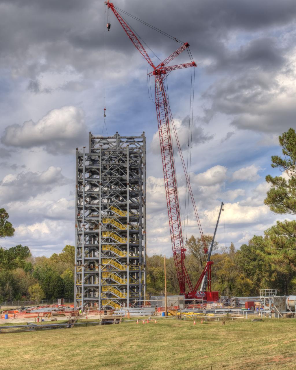
TEST STAND 4693 CONSTRUCTION RISES ABOVE THE TREE LINE. OCTOBER 23, 2015
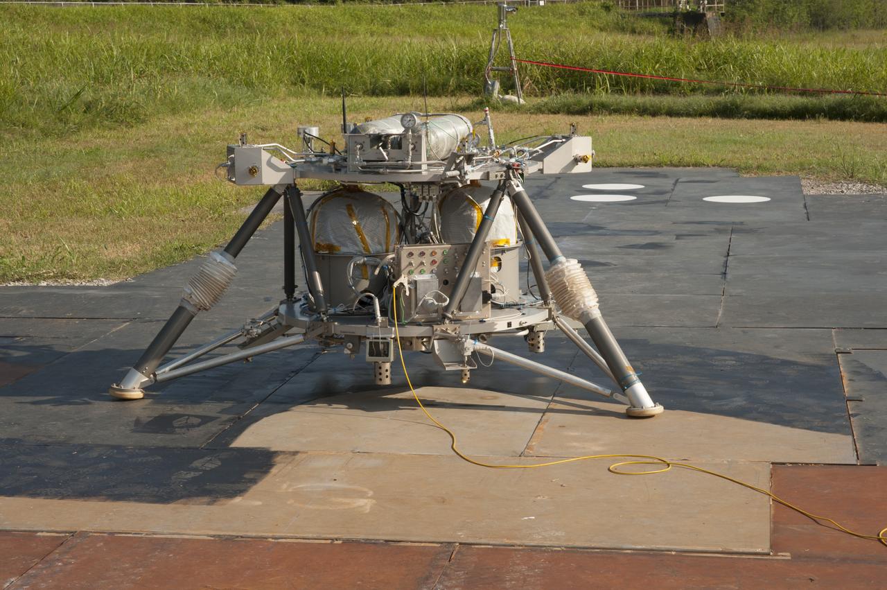
PHOTOGRAPH IN WEST TEST AREA OF THE "MIGHT EAGLE" LANDER
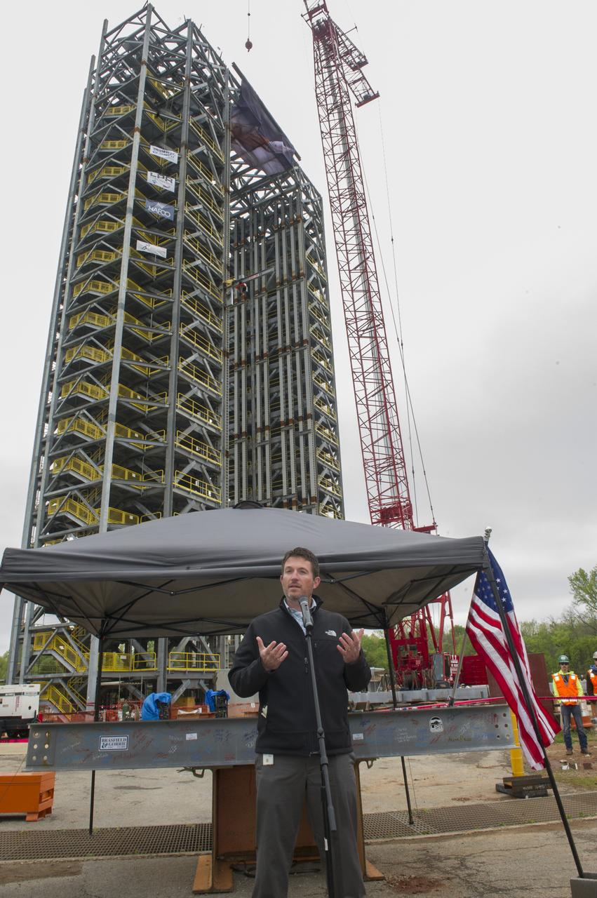
PHIL HENDRIX, SPEAKS TO THE CROWD IN FRONT OF A STEEL BEAM DESTINED FOR TEST STAND 4693 DURING THE STRUCTURE'S TOPPING OUT CEREMONY APRIL 12.
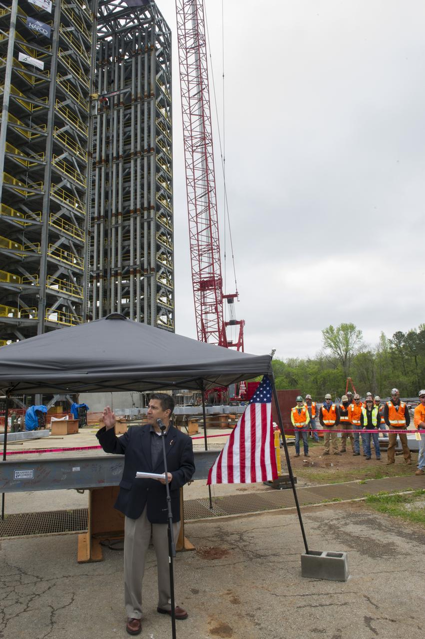
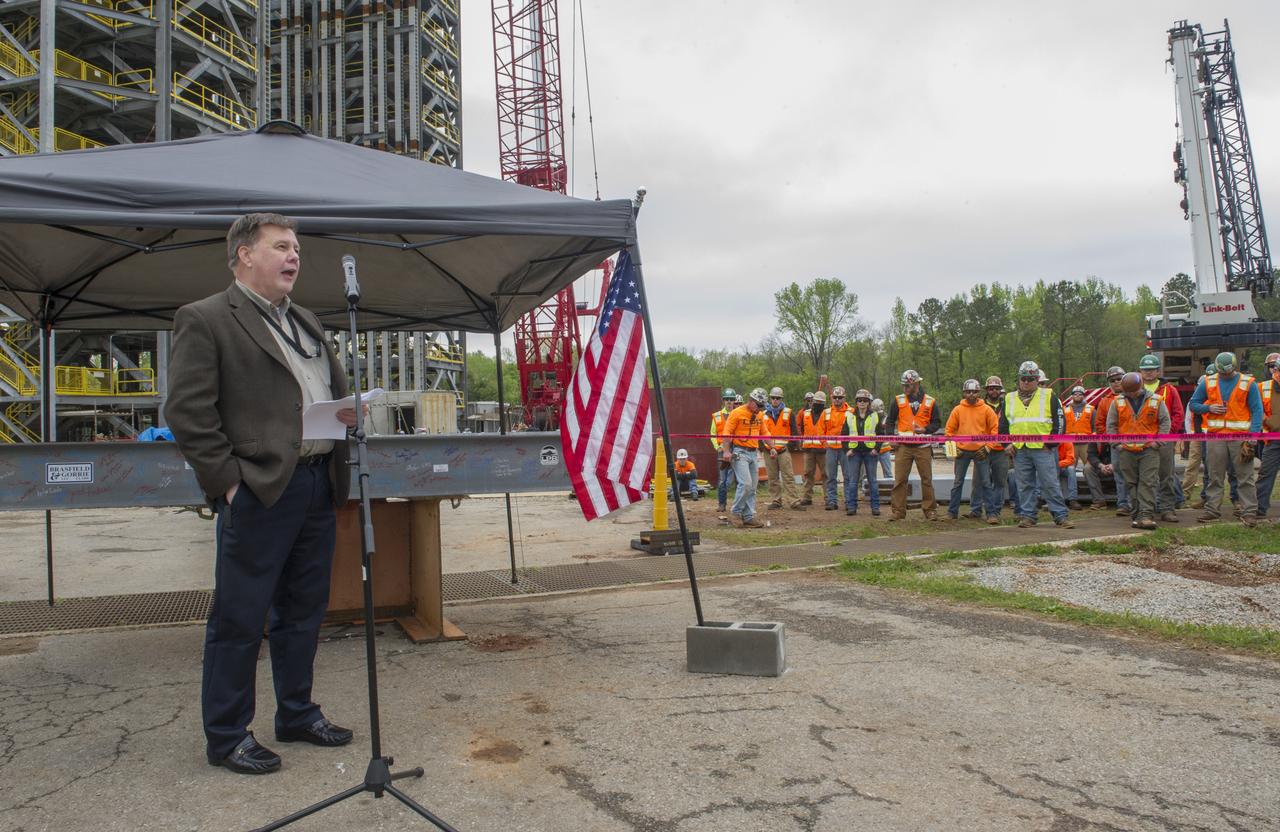
TIM FLORES SPEAKS TO THE CROWD IN FRONT OF A STEEL BEAM DESTINED FOR TEST STAND 4693 DURING THE STRUCTURE'S TOPPING OUT CEREMONY APRIL 12.
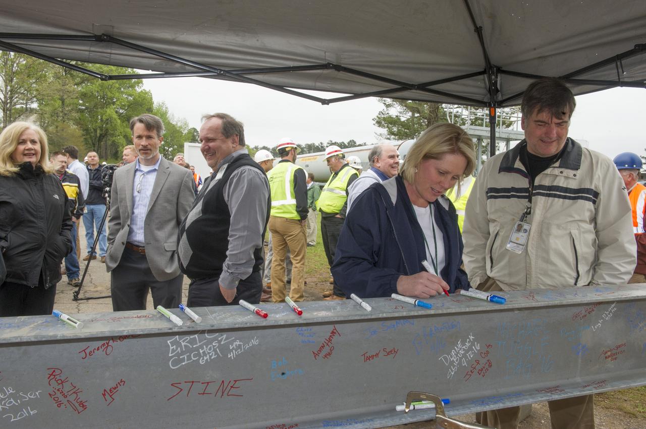
HEATHER HANEY SIGNS FINAL BEAM TO BE PLACED ATOP TEST STAND 4693 DURING THE STRUCTURE'S TOPPING OUT CEREMONY
BOB DEVLIN, DEPUTY DIRECTOR OF MARSHALL'S OFFICE OF CENTER OPERATIONS, SPEAKS TO THE CROWD IN FRONT OF A STEEL BEAM DESTINED FOR TEST STAND 4693 DURING THE STRUCTURE'S TOPPING OUT CEREMONY APRIL 12.
Aerial photograph of the MSFC West Test area with the T-Stand in the foreground
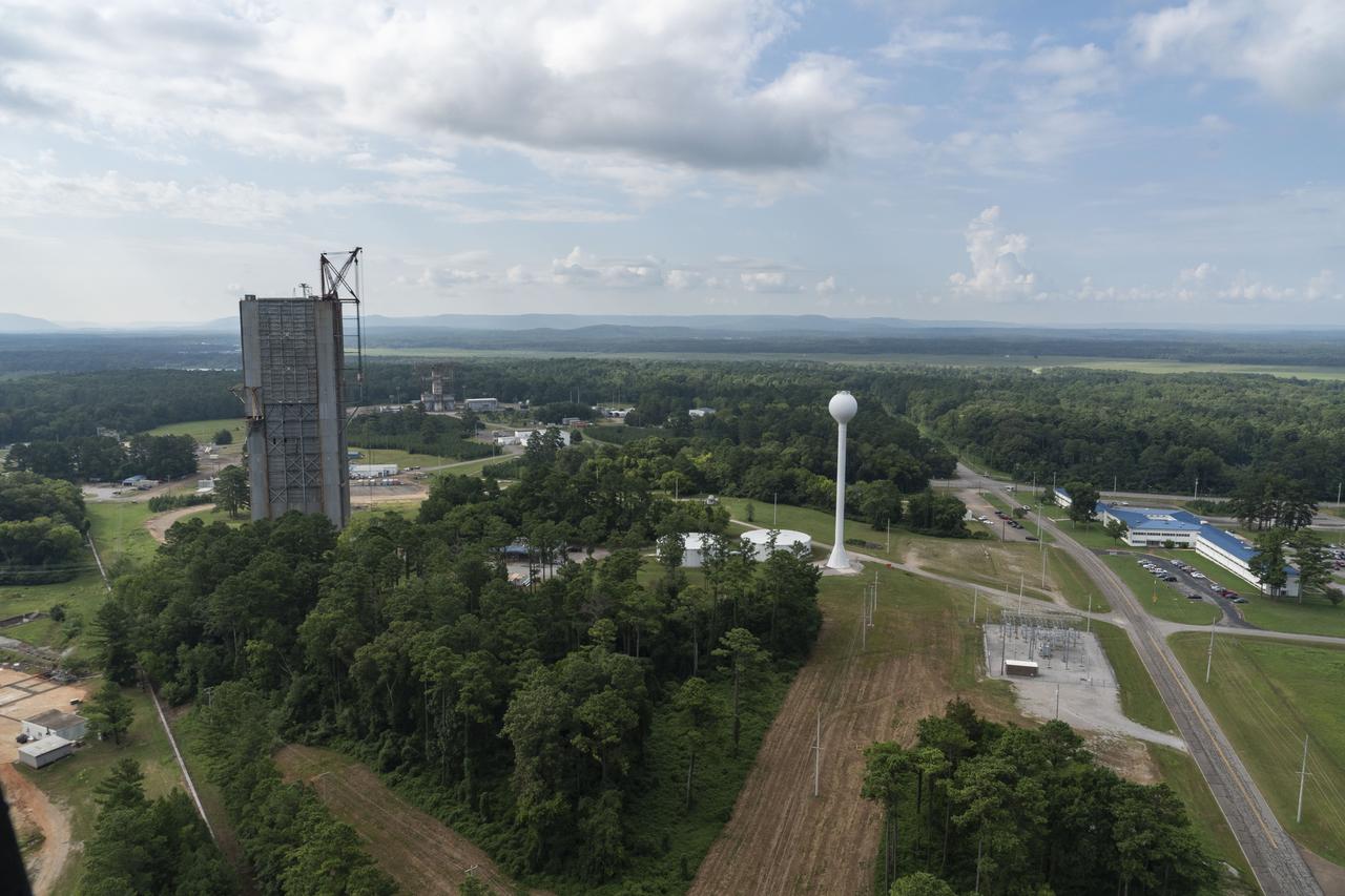
Aerial photograph of the MSFC West Test Area with building 4666 on the right
The Liquid Oxygen Test Article was lifted onto the Kmag. Various electronic components will be installed then the article will be moved into test stand 4697.
The Liquid Oxygen Test Article was lifted onto the Kmag. Various electronic components will be installed then the article will be moved into test stand 4697.
The Liquid Oxygen Test Article was lifted onto the Kmag. Various electronic components will be installed then the article will be moved into test stand 4697.
The Liquid Oxygen Test Article was lifted onto the Kmag. Various electronic components will be installed then the article will be moved into test stand 4697.
The Liquid Oxygen Test Article was lifted onto the Kmag. Various electronic components will be installed then the article will be moved into test stand 4697.
The Liquid Oxygen Test Article was lifted onto the Kmag. Various electronic components will be installed then the article will be moved into test stand 4697.
The Liquid Oxygen Test Article was lifted onto the Kmag. Various electronic components will be installed then the article will be moved into test stand 4697.
The Liquid Oxygen Test Article was lifted onto the Kmag. Various electronic components will be installed then the article will be moved into test stand 4697.
The Liquid Oxygen Test Article was lifted onto the Kmag. Various electronic components will be installed then the article will be moved into test stand 4697.
The Liquid Oxygen Test Article was lifted onto the Kmag. Various electronic components will be installed then the article will be moved into test stand 4697.
The Liquid Oxygen Test Article was lifted onto the Kmag. Various electronic components will be installed then the article will be moved into test stand 4697.
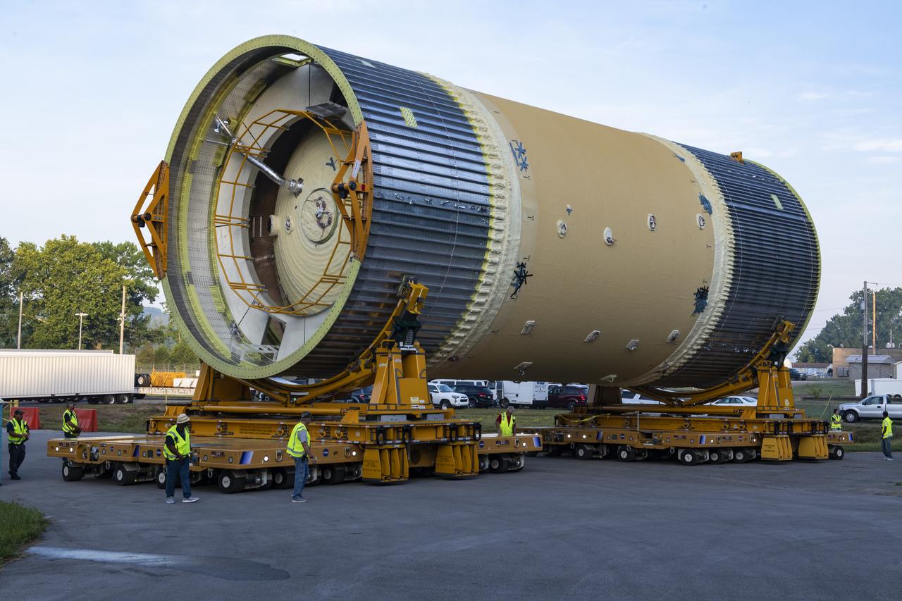
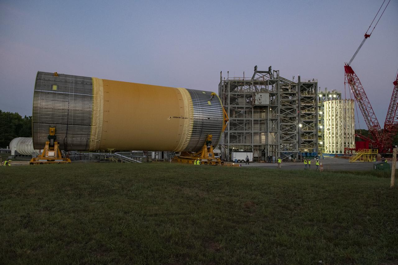
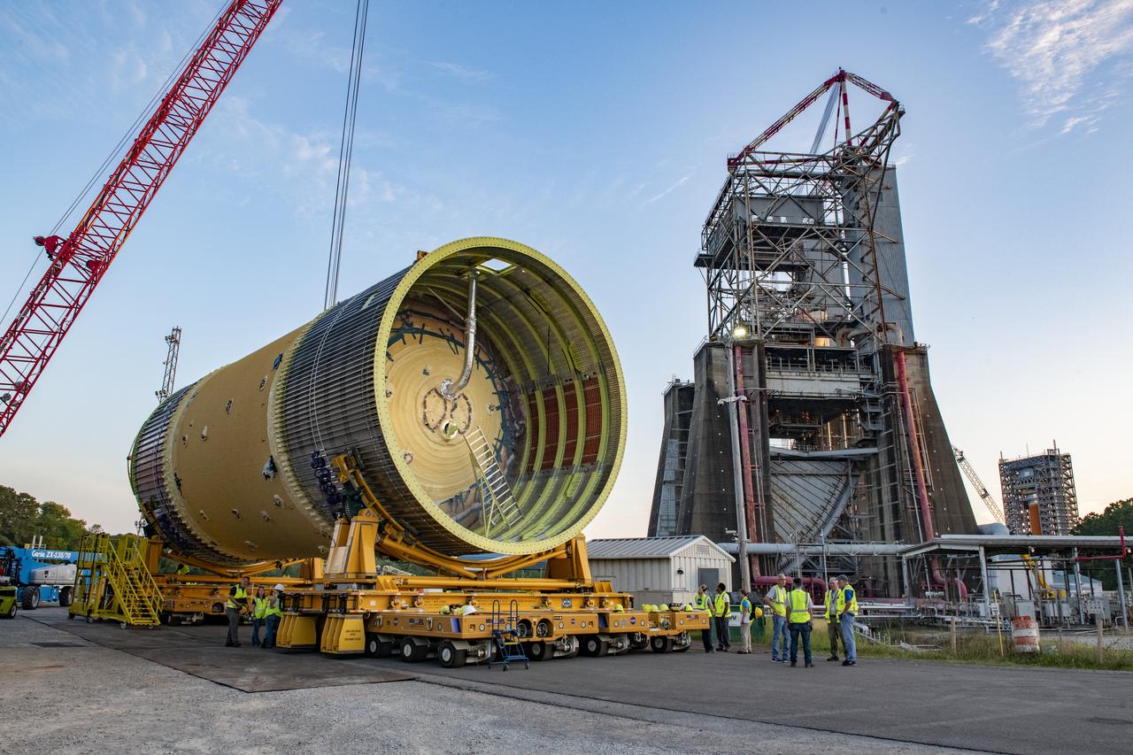
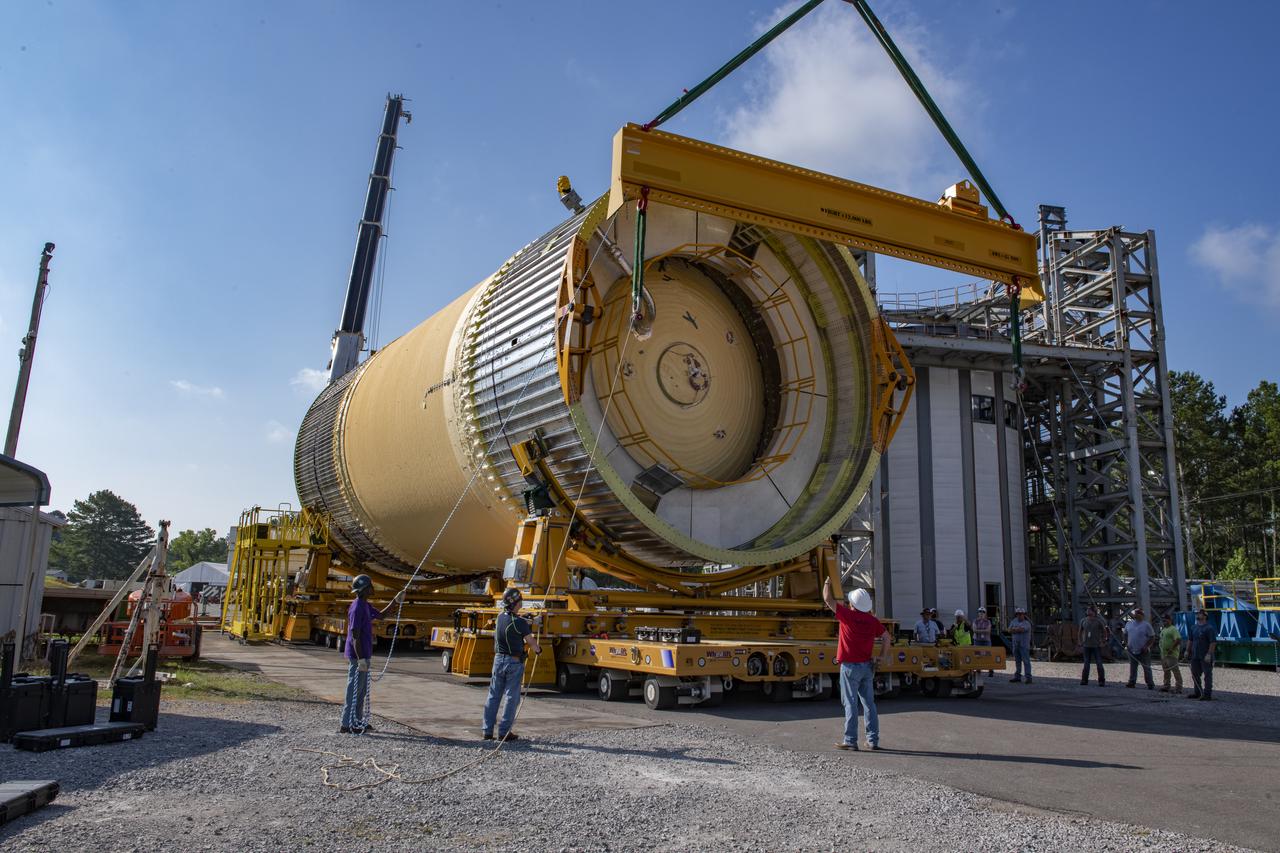
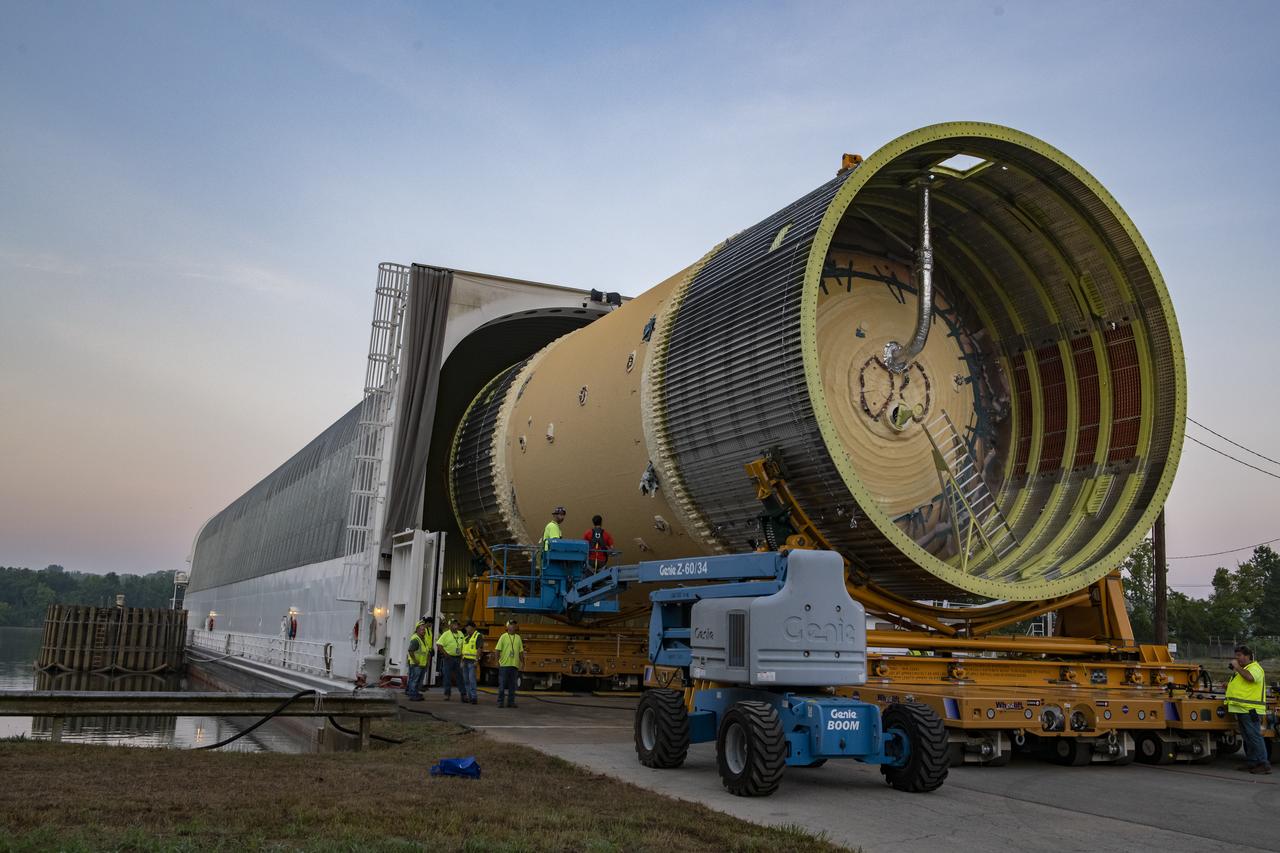
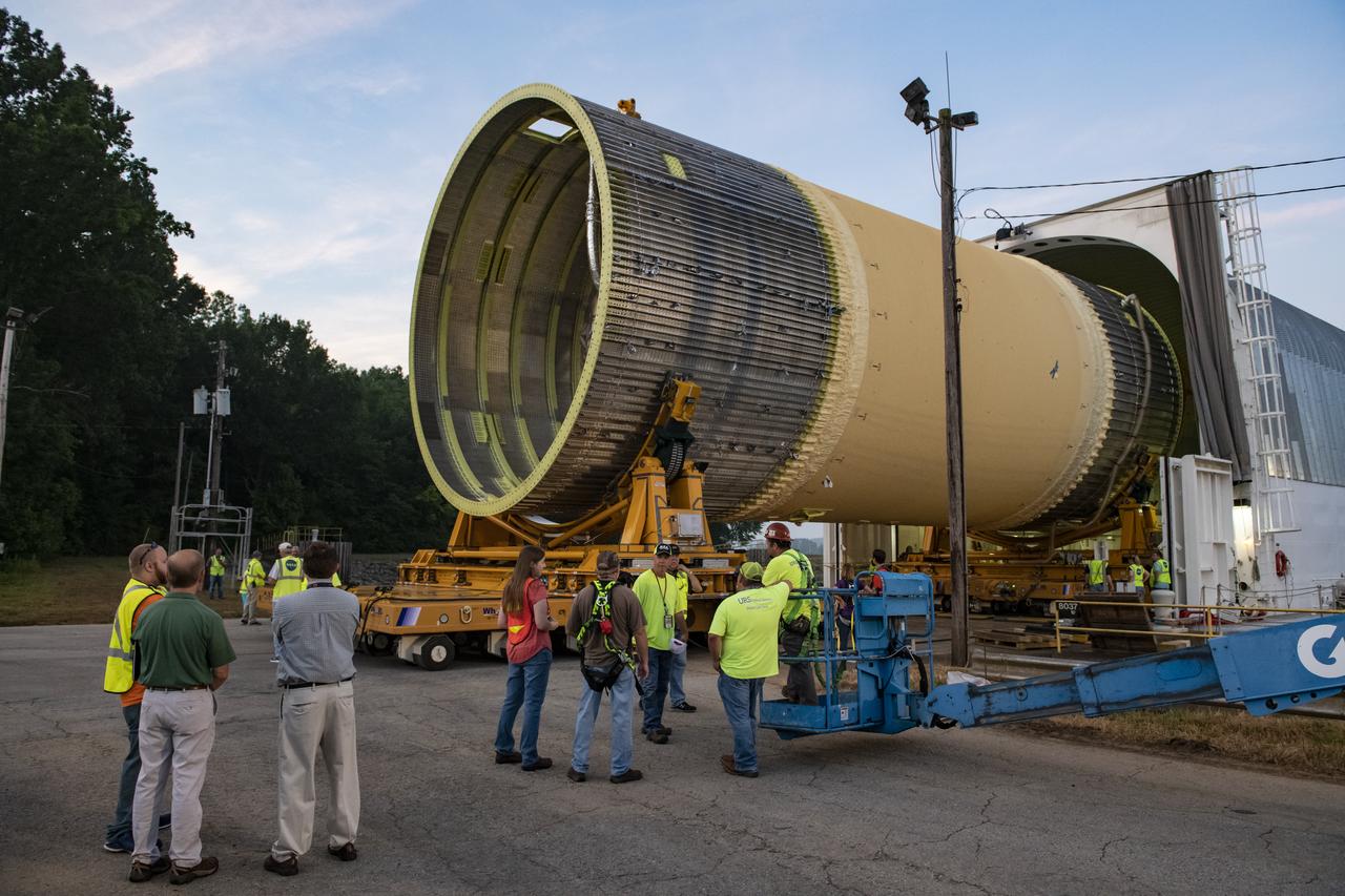
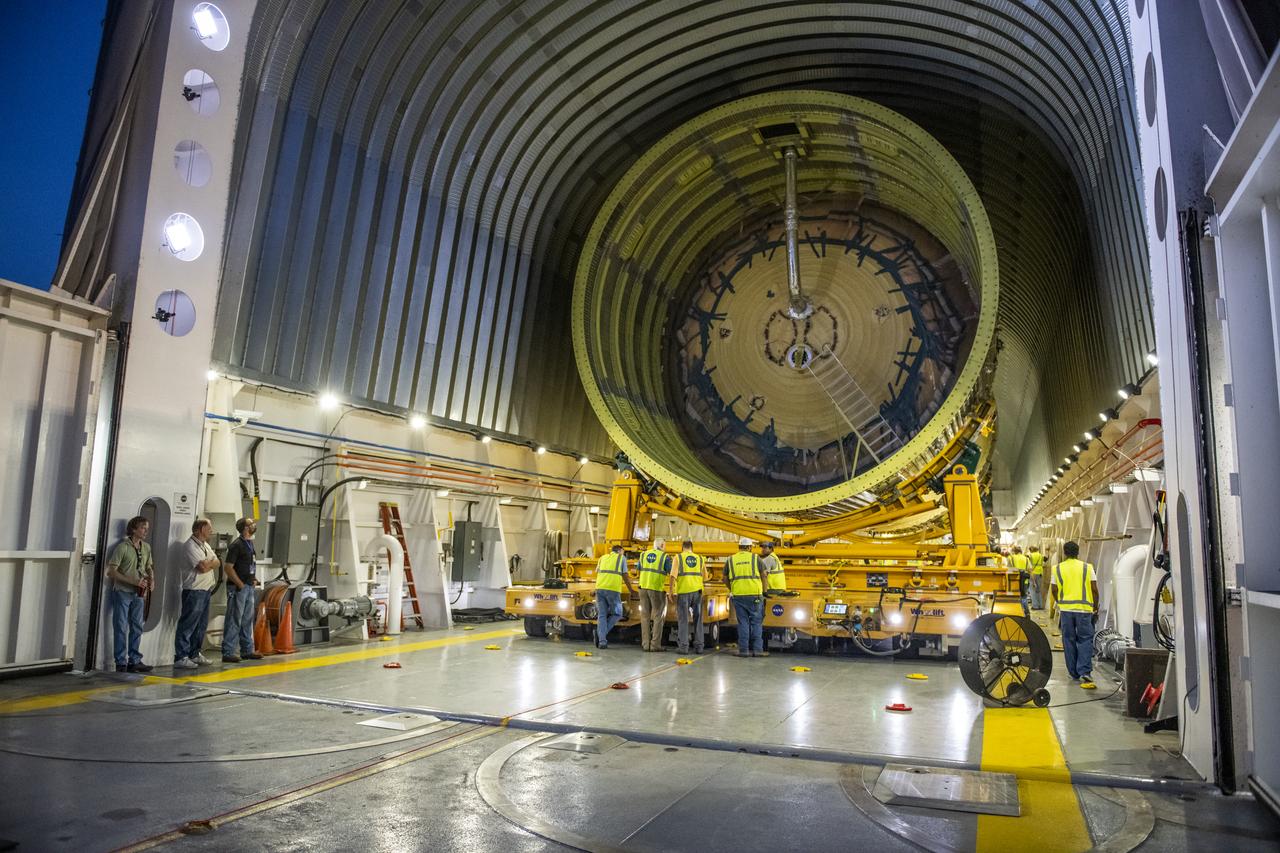
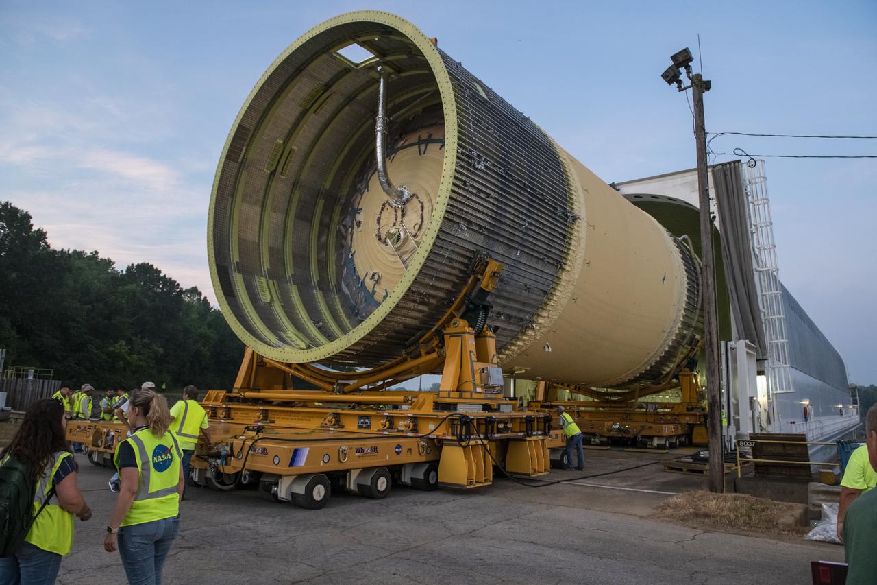
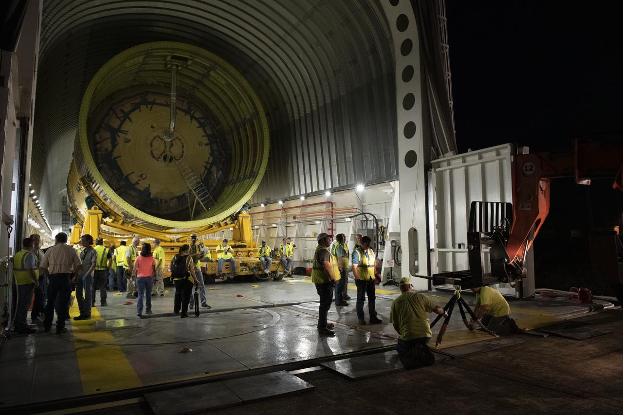
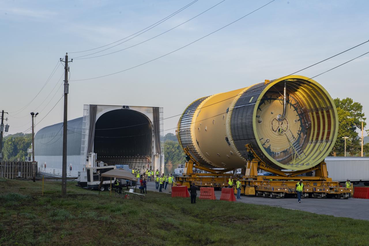
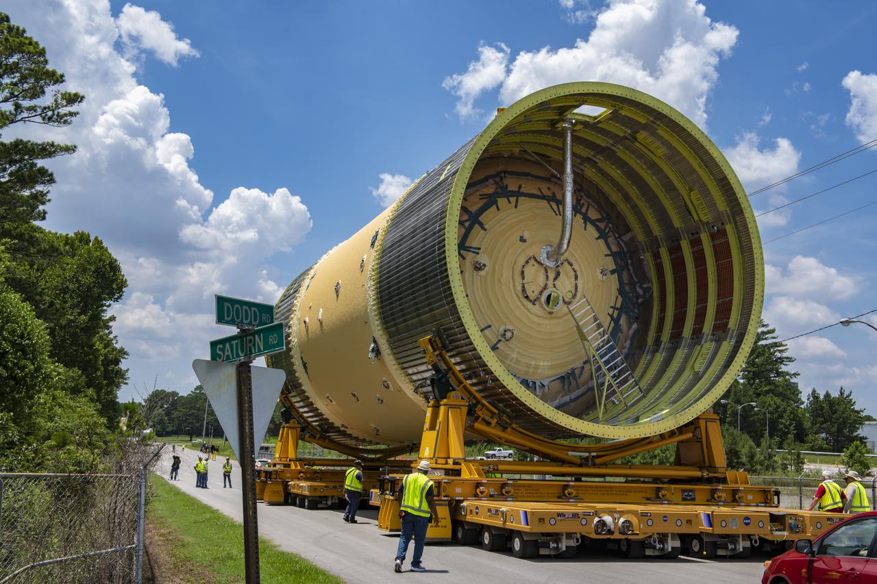
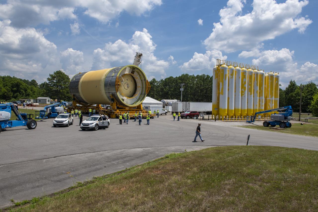
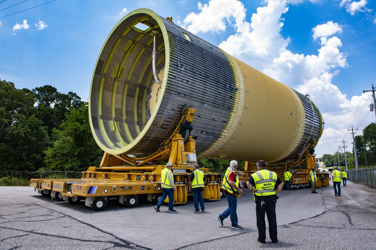
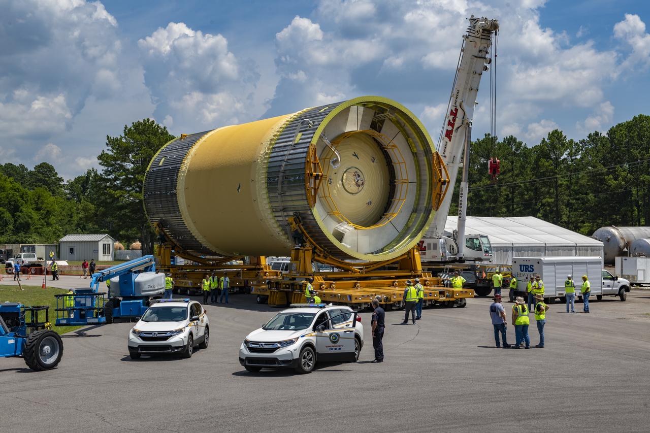
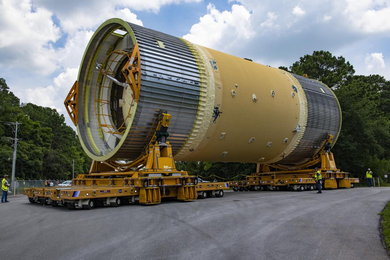
The Liquid Oxygen (LOX) tank was moved from the Pegasus barge to the west test area for placement in test stand.
The Liquid Oxygen (LOX) tank was moved from the Pegasus barge to the west test area for placement in test stand.
The Liquid Oxygen (LOX) tank was moved from the Pegasus barge to the west test area for placement in test stand.
The Liquid Oxygen (LOX) tank was moved from the Pegasus barge to the west test area for placement in test stand.

The Liquid Oxygen (LOX) tank was moved from the Pegasus barge to the west test area for placement in test stand.
The Liquid Oxygen (LOX) tank was moved from the Pegasus barge to the west test area for placement in test stand.
The Liquid Oxygen (LOX) tank was moved from the Pegasus barge to the west test area for placement in test stand.

The Liquid Oxygen (LOX) tank was moved from the Pegasus barge to the west test area for placement in test stand.
The Liquid Oxygen (LOX) tank was moved from the Pegasus barge to the west test area for placement in test stand.
The Liquid Oxygen (LOX) tank was moved from the Pegasus barge to the west test area for placement in test stand.
The Liquid Oxygen (LOX) tank was moved from the Pegasus barge to the west test area for placement in test stand.
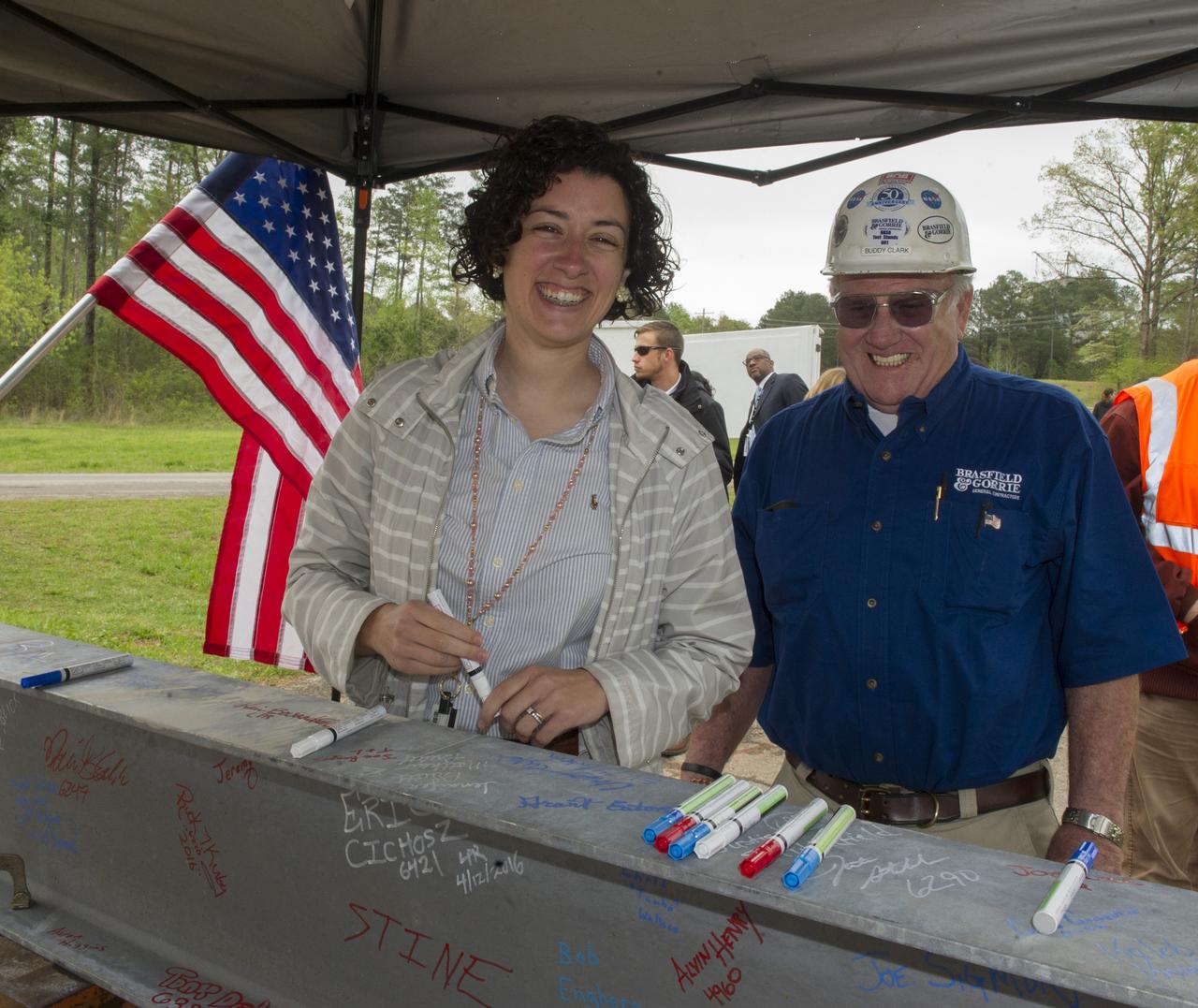
JENNIFER PRUITT AND BUDDY CLARK SMILE FOR THE CAMERA BEFORE SIGNING THE FINAL BEAM TO BE PLACED ATOP TEST STAND 4693 DURING THE STRUCTURE'S TOPPING OUT CEREMONY
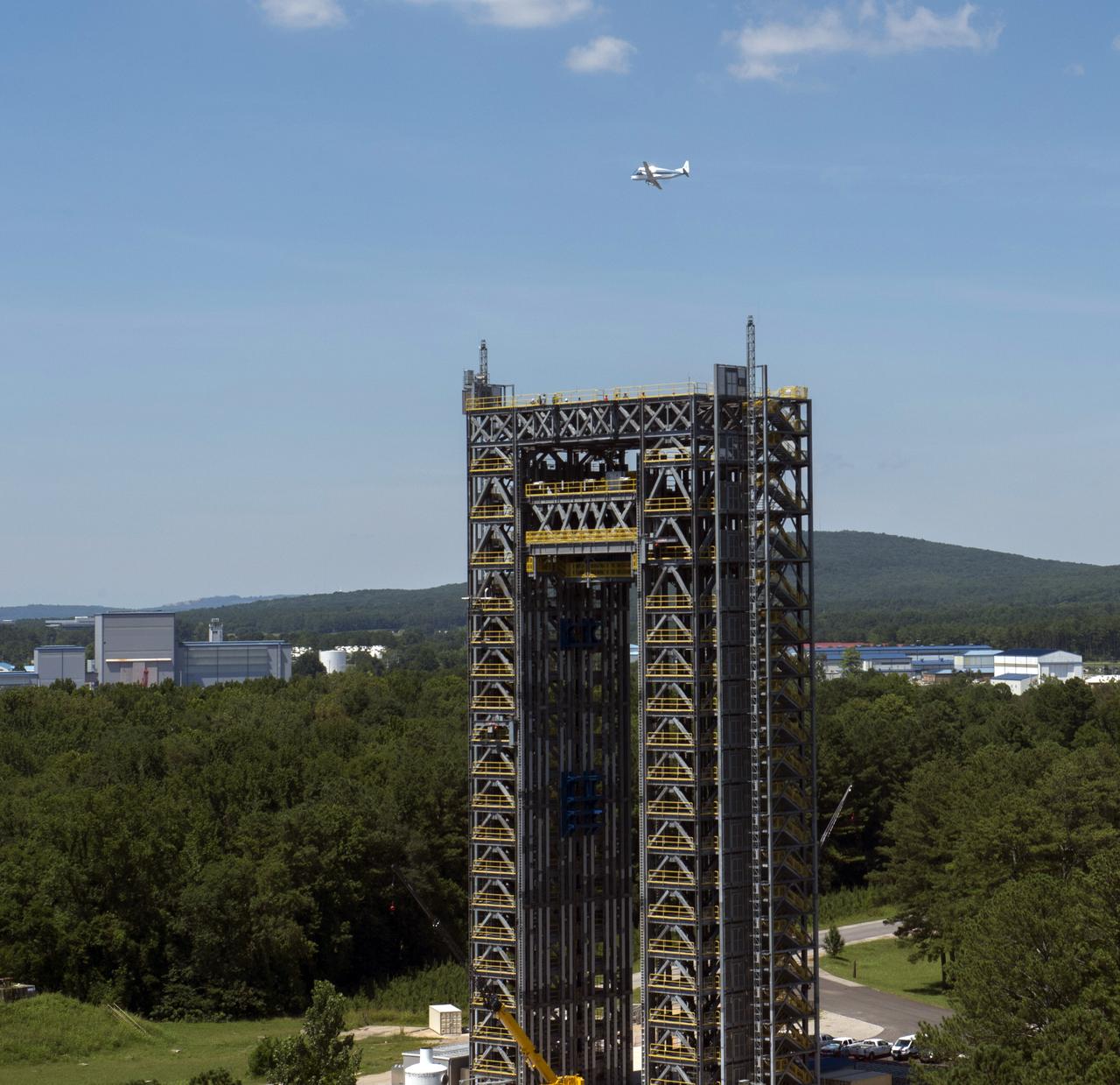
NASA's Super Guppie flies over Marshall Space Flight Center's test stand 4693 in the west test area.
CLOSE-UP OF H-1 ENGINE INSTALLED ON SATURN S-1B STAGE (SA-T) NEAR PROPULSION AND STRUCTURAL TEST FACILITY (BUILDING 4572) AT THE GEORGE C. MARSHALL SPACE FLIGHT CENTER.
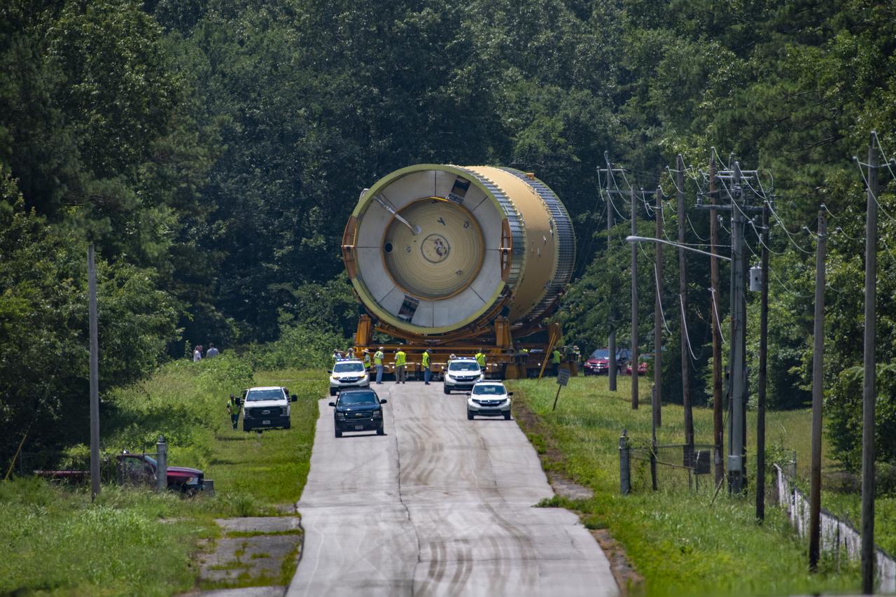
The Liquid Oxygen (LOX) tank was moved from the Pegasus barge to the west test area for placement in test stand 4697.
The Liquid Oxygen (LOX) tank was moved from the Pegasus barge to the west test area for placement in test stand 4697.
The Liquid Oxygen (LOX) tank was moved from the Pegasus barge to the west test area for placement in test stand 4697.
The Liquid Oxygen (LOX) tank was moved from the Pegasus barge to the west test area for placement in test stand 4697.
The Liquid Oxygen (LOX) tank was moved from the Pegasus barge to the west test area for placement in test stand 4697.

The Liquid Oxygen (LOX) tank was moved from the Pegasus barge to the west test area for placement in test stand 4697.
The Liquid Oxygen (LOX) tank was moved from the Pegasus barge to the west test area for placement in test stand 4697.
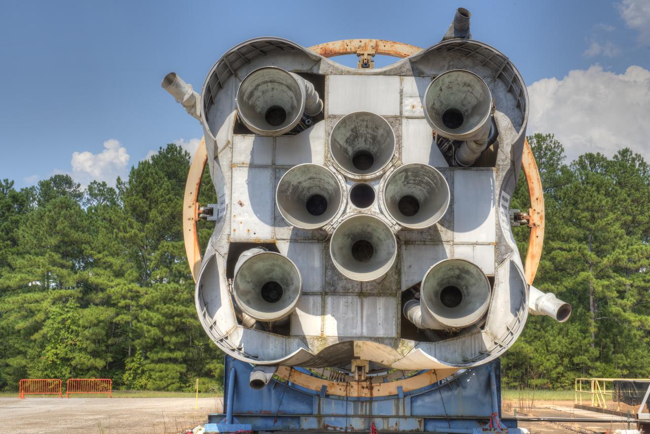
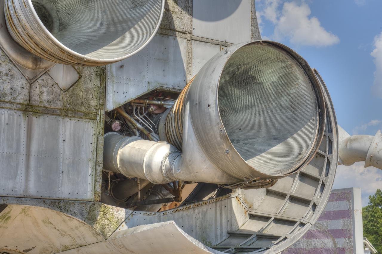
CLOSE-UP OF AFT END OF SATURN S-1B STAGE (SA-T) NEAR PROPULSION AND STRUCTURAL TEST FACILITY (BUILDING 4572) AT THE GEORGE C. MARSHALL SPACE FLIGHT CENTER IN HUNTSVILLE, ALABAMA.
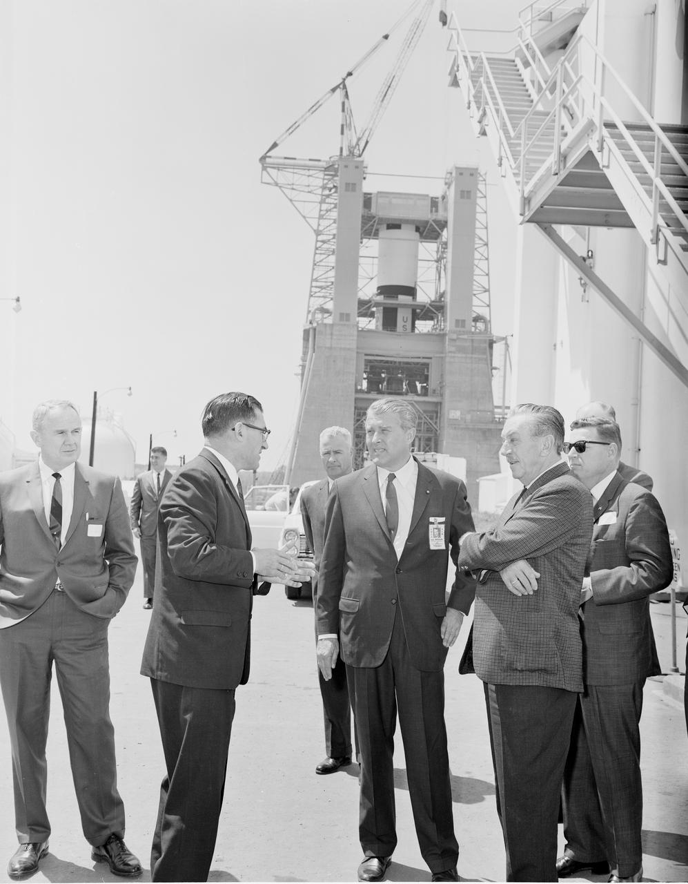
Walt Disney toured the West Test Area during his visit to the Marshall Space Flight Center on April 13, 1965. The three in center foreground are Karl Heimburg, Director, Test Division; Dr. von Braun, Director, MSFC; and Walt Disney. The Dynamic Test Stand with the S-1C stage being installed is in the background.
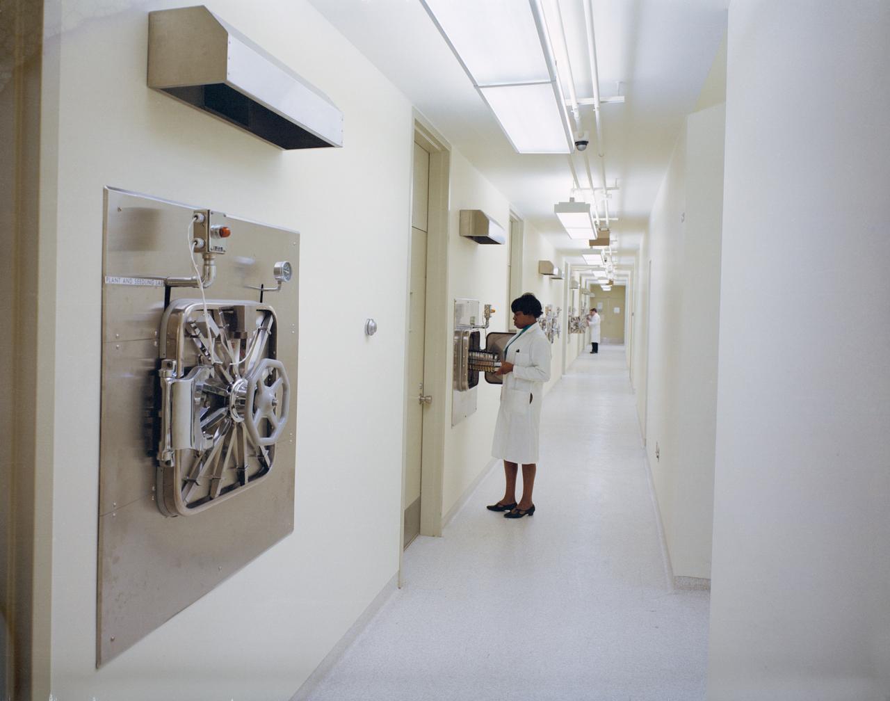
Biological Test Laboratory, Sample Operations Area, Lunar Receiving Laboratory, bldg 37, Manned Spacecraft Center, Houston, Texas.
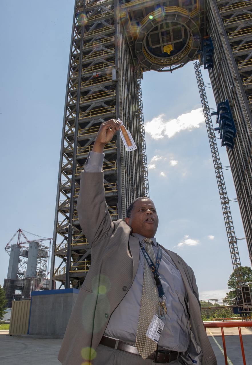
Students from the Tarik Black Foundation attend a STEM program at MSFC and visit SLS Test Stand 4693 in West Test Area. Gary Willis tells Tarik Black Foundation students about Test Stand 4693 and its importance in SLS development.
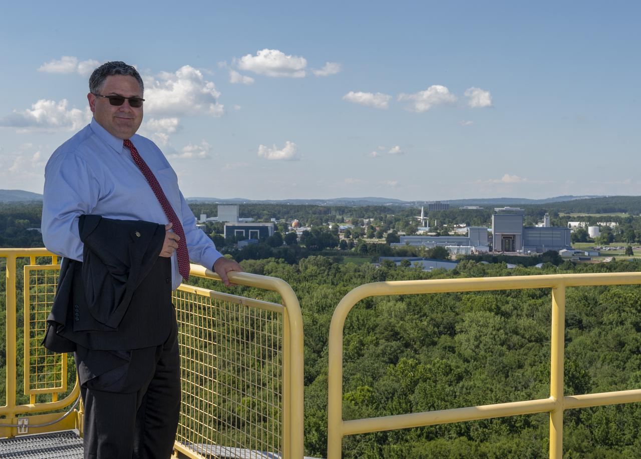
Retiring Marshall Space Flight Center Director Todd May on top of test stand 4693 in MSFC's west test area with MSFC in the background
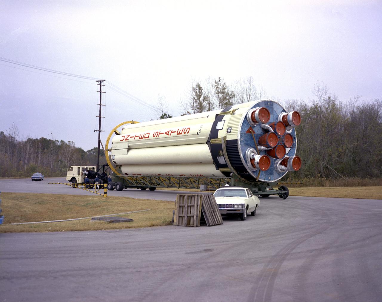
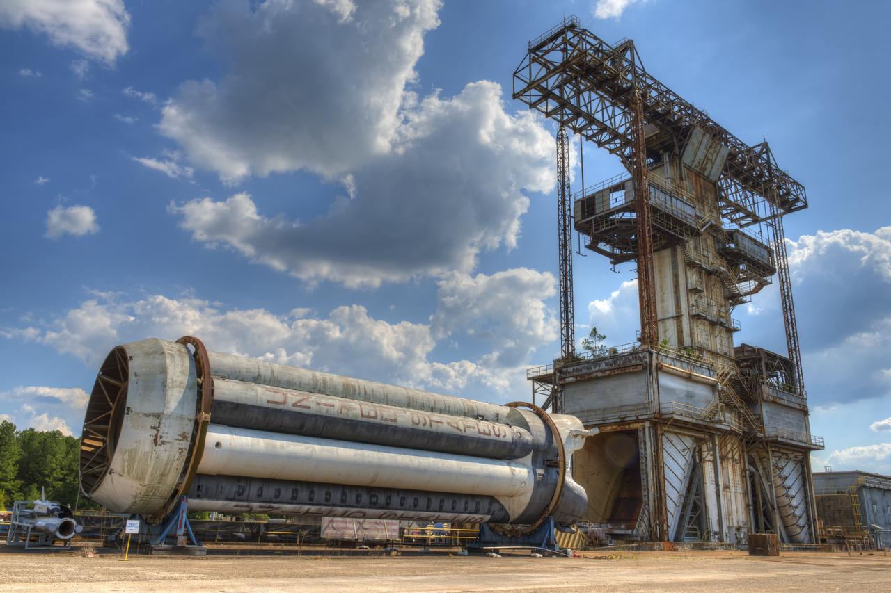
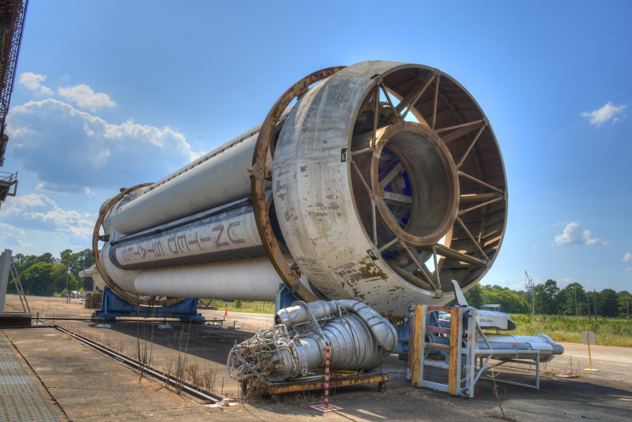
S-IB-211, the flight version of the Saturn IB launch vehicle's first (S-IVB) stage, on its way to Marshall Space Flight Center's (MSFC's) west test area. Between December 1967 and April 1968, the stage would undergo seven static test firings. The S-IB, developed by the MSFC and built by the Chrysler Corporation at the Michoud Assembly Facility near New Orleans, Louisiana, utilized eight H-1 engines and each produced 200,000 pounds of thrust.
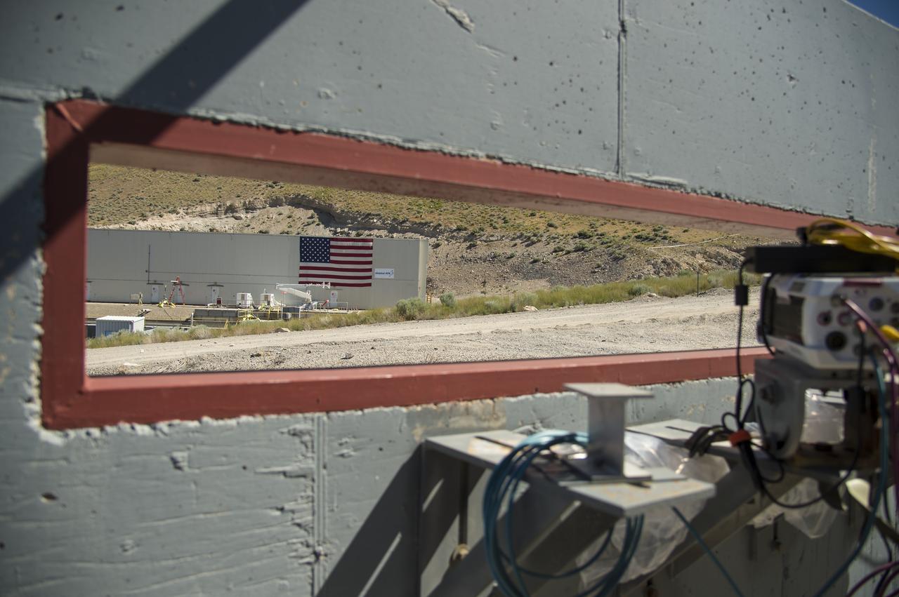
The test area where the second and final qualification motor (QM-2) test for the Space Launch System’s booster is seen through the window of a camera bunker, Sunday, June 26, 2016, at Orbital ATK Propulsion Systems test facilities in Promontory, Utah. The test is scheduled for Tuesday, June 28 at 10:05 a.m. EDT (8:05 a.m. MDT). Photo Credit: (NASA/Bill Ingalls)
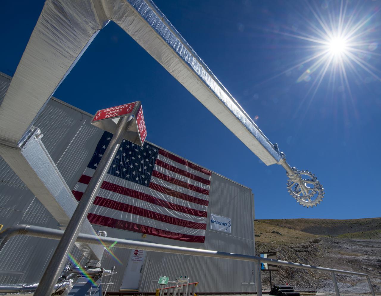
The quench system arm and nozzle are seen at the test area where the second and final qualification motor (QM-2) test for the Space Launch System’s booster will take place, Sunday, June 26, 2016, at Orbital ATK Propulsion Systems test facilities in Promontory, Utah. The test is scheduled for Tuesday, June 28 at 10:05 a.m. EDT (8:05 a.m. MDT). Photo Credit: (NASA/Bill Ingalls)
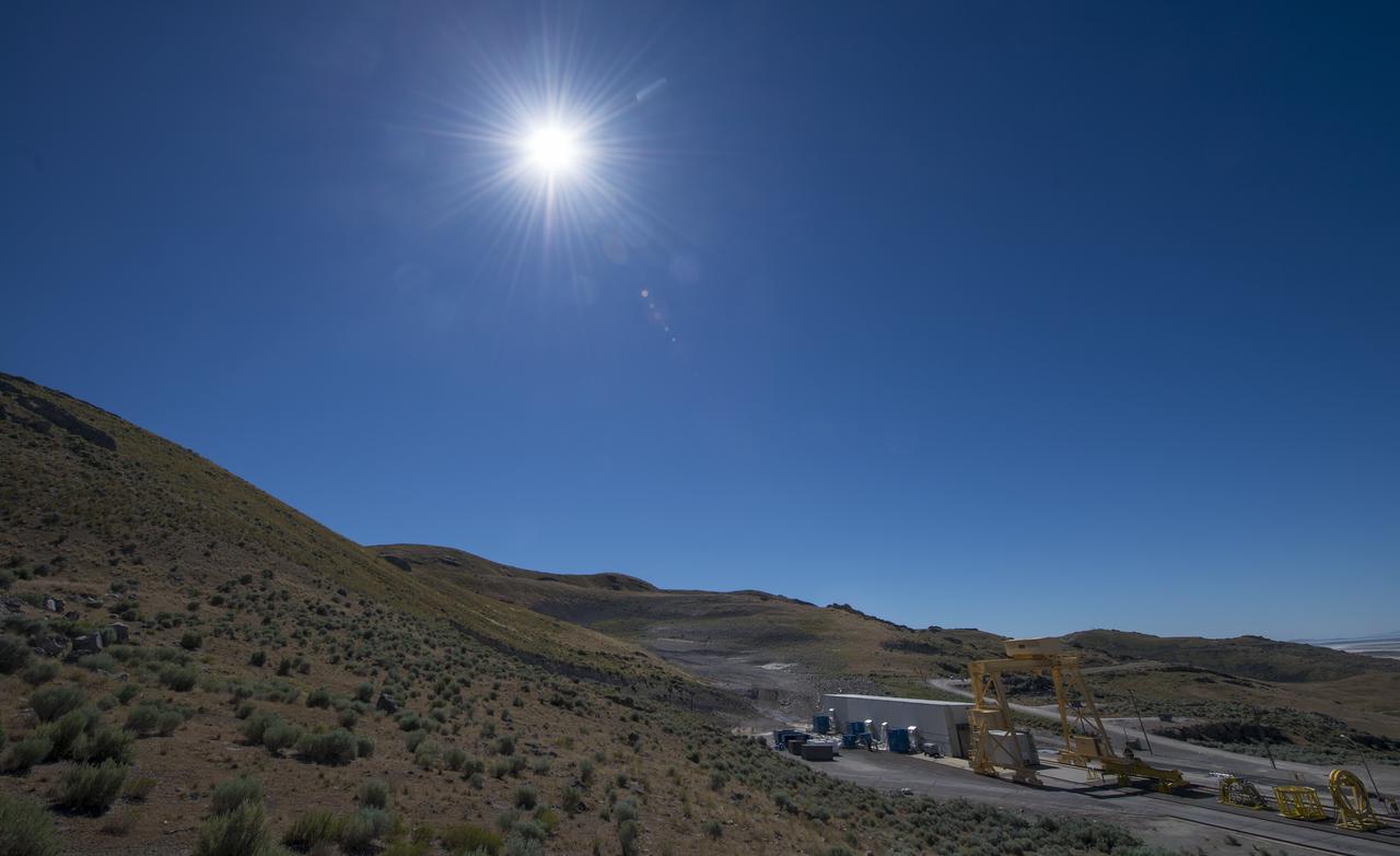
The test area where the second and final qualification motor (QM-2) test for the Space Launch System’s booster is seen Sunday, June 26, 2016, at Orbital ATK Propulsion Systems test facilities in Promontory, Utah. The test is scheduled for Tuesday, June 28 at 10:05 a.m. EDT (8:05 a.m. MDT). Photo Credit: (NASA/Bill Ingalls)
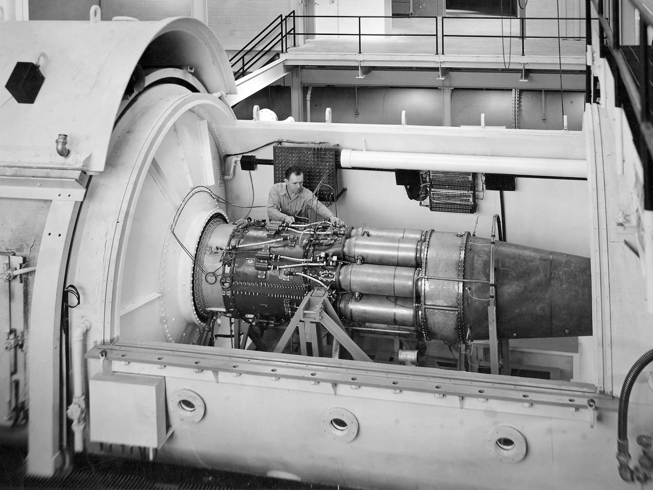
One of the two altitude simulating-test chambers in Engine Research Building at the National Advisory Committee for Aeronautics (NACA) Lewis Flight Propulsion Laboratory. The two chambers were collectively referred to as the Four Burner Area. NACA Lewis’ Altitude Wind Tunnel was the nation’s first major facility used for testing full-scale engines in conditions that realistically simulated actual flight. The wind tunnel was such a success in the mid-1940s that there was a backlog of engines waiting to be tested. The Four Burner chambers were quickly built in 1946 and 1947 to ease the Altitude Wind Tunnel’s congested schedule. The Four Burner Area was located in the southwest wing of the massive Engine Research Building, across the road from the Altitude Wind Tunnel. The two chambers were 10 feet in diameter and 60 feet long. The refrigeration equipment produced the temperatures and the exhauster equipment created the low pressures present at altitudes up to 60,000 feet. In 1947 the Rolls Royce Nene was the first engine tested in the new facility. The mechanic in this photograph is installing a General Electric J-35 engine. Over the next ten years, a variety of studies were conducted using the General Electric J-47 and Wright Aeronautical J-65 turbojets. The two test cells were occasionally used for rocket engines between 1957 and 1959, but other facilities were better suited to the rocket engine testing. The Four Burner Area was shutdown in 1959. After years of inactivity, the facility was removed from the Engine Research Building in late 1973 in order to create the High Temperature and Pressure Combustor Test Facility.
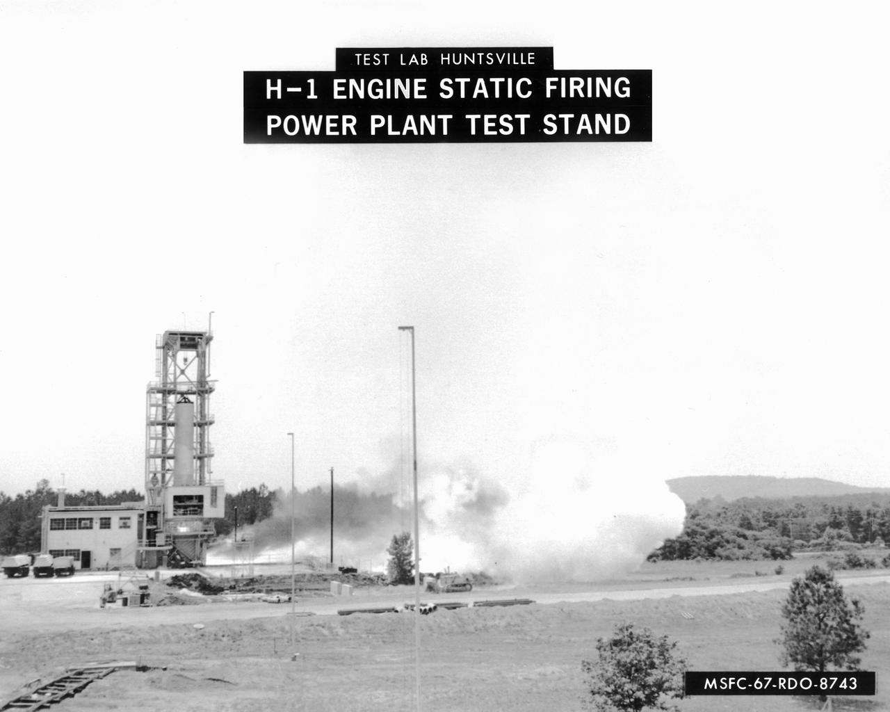
This image depicts a firing of a single H-1 engine at the Marshall Space Flight Center’s (MSFC’s) Power Plant test stand. This 1950s test stand, inherited from the Army, was used to test fire engines until the Test Area was completed in the latter 1960s. The H-1 engine was the workhorse of the first Saturn launch vehicles and used in the Saturn I, Block 1 and II, and in the Saturn IB. The eight H-1 engines were attached to a thrust frame on the vehicle’s aft end in two different ways. Four engines are rigidly attached to the inboard position and canted at a three degree angle to the long axis of the booster. The other four engines, mounted in the outboard position, are canted at six degrees.
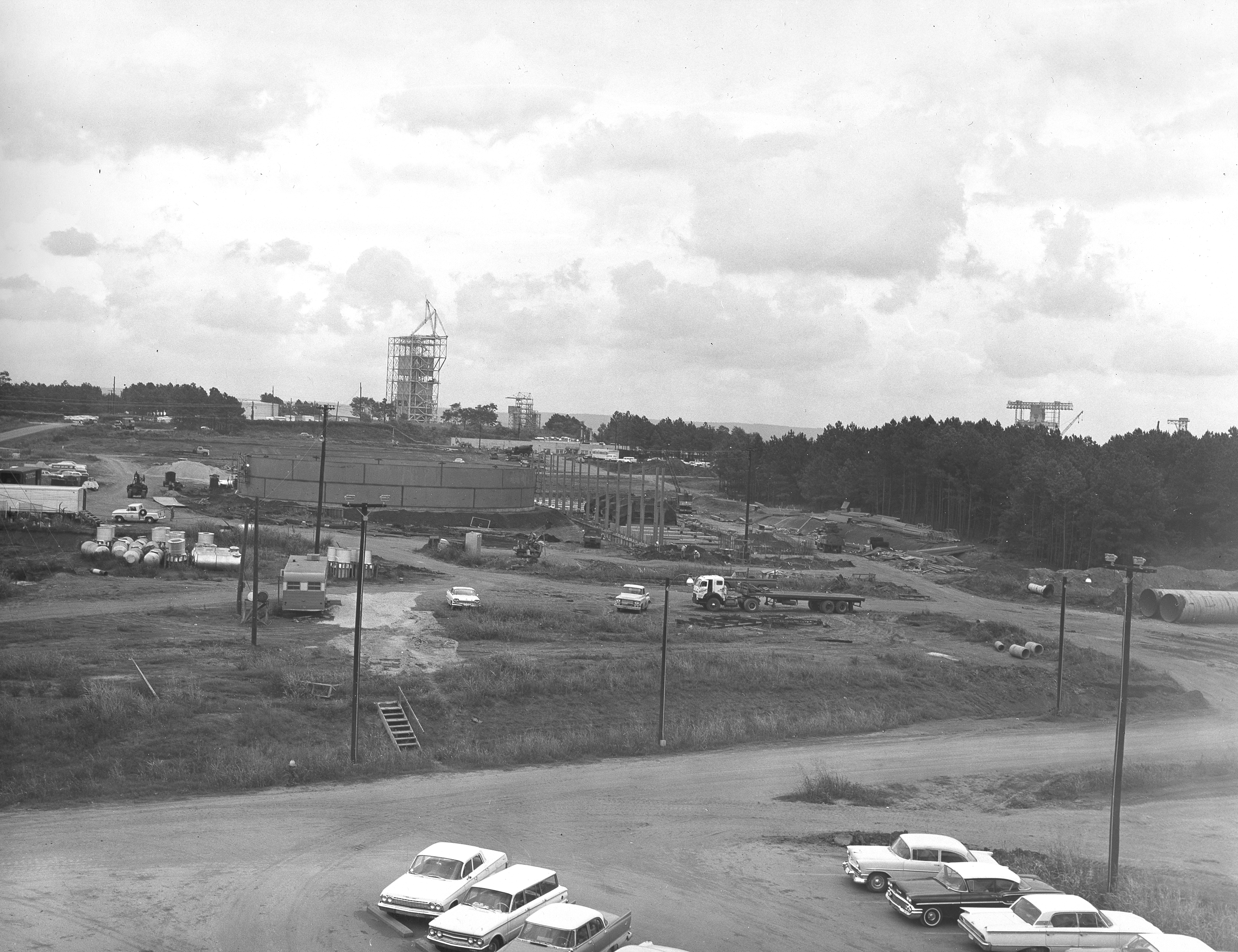
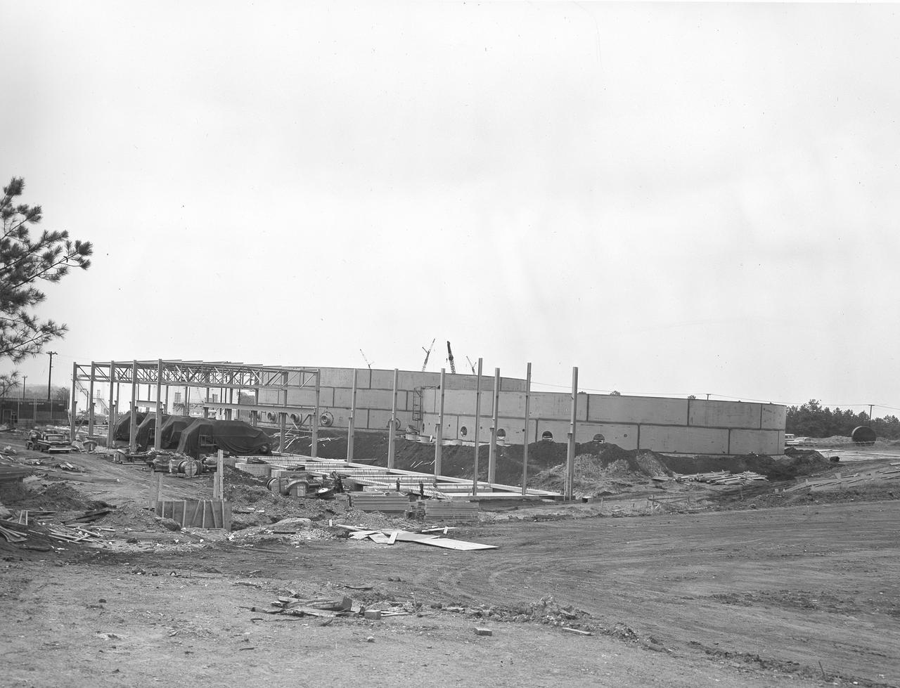
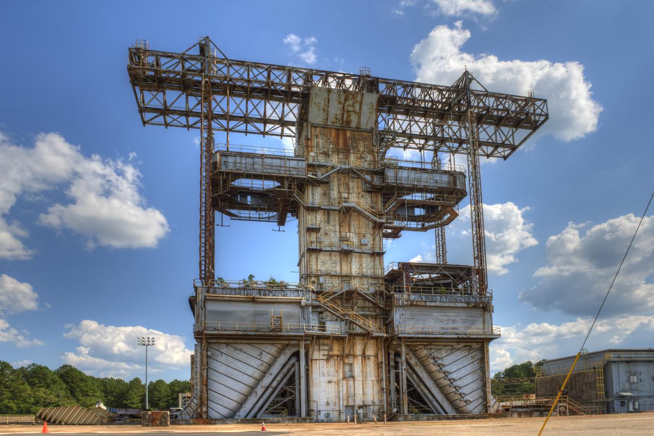
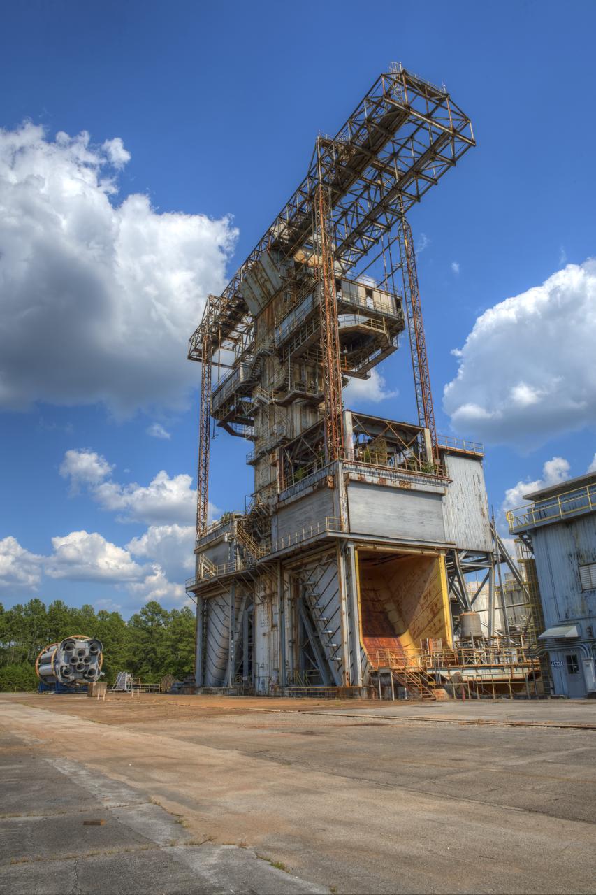
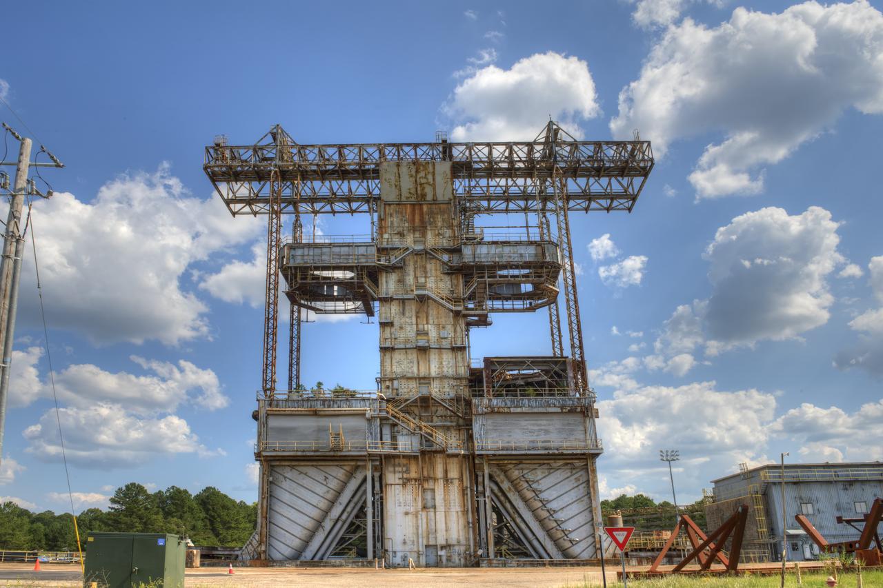
At its founding, the Marshall Space Flight Center (MSFC) inherited the Army’s Jupiter and Redstone test stands, but much larger facilities were needed for the giant stages of the Saturn V. From 1960 to 1964, the existing stands were remodeled and a sizable new test area was developed. The new comprehensive test complex for propulsion and structural dynamics was unique within the nation and the free world, and they remain so today because they were constructed with foresight to meet the future as well as on going needs. Construction of the S-IC Static test stand complex began in 1961 in the west test area of MSFC, and was completed in 1964. The S-IC static test stand was designed to develop and test the 138-ft long and 33-ft diameter Saturn V S-IC first stage, or booster stage, weighing in at 280,000 pounds. Required to hold down the brute force of a 7,500,000-pound thrust produced by 5 F-1 engines, the S-IC static test stand was designed and constructed with the strength of hundreds of tons of steel and 12,000,000 pounds of cement, planted down to bedrock 40 feet below ground level. The foundation walls, constructed with concrete and steel, are 4 feet thick. The base structure consists of four towers with 40-foot-thick walls extending upward 144 feet above ground level. The structure was topped by a crane with a 135-foot boom. With the boom in the upright position, the stand was given an overall height of 405 feet, placing it among the highest structures in Alabama at the time. In addition to the stand itself, related facilities were constructed during this time. Built to the northeast east was a newly constructed Pump House. Its function was to provide water to the stand to prevent melting damage during testing. The water was sprayed through small holes in the stand’s 1900 ton flame deflector at the rate of 320,000 gallons per minute. This photograph of the Pump House area was taken August 13, 1963. The massive round water storage tanks can be seen to the left of the Pump House.
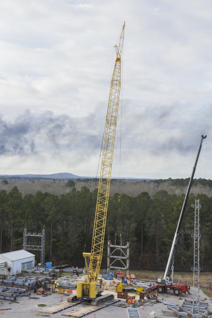
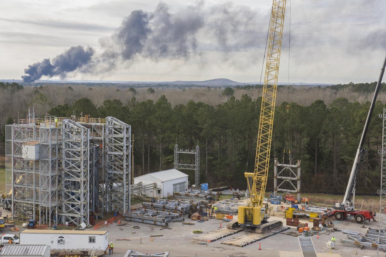
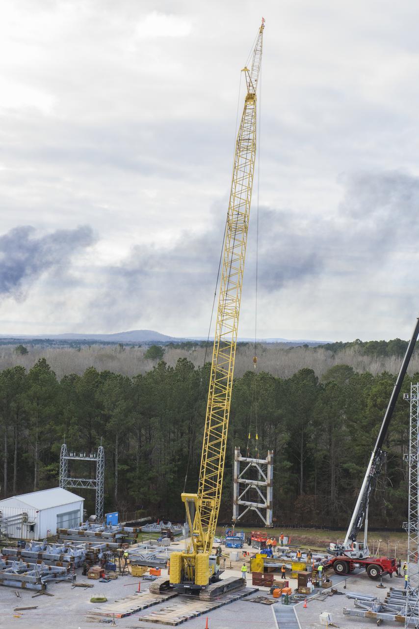
A CRANE MOVES THE FIRST STEEL TIER TO BE BOLTED INTO PLACE ON JAN. 6, FOR WELDING OF A SECOND NEW STRUCTURAL TEST STAND AT NASA'S MARSHALL SPACE FLIGHT CENTER IN HUNTSVILLE, ALABAMA -- CRITICAL TO DEVELOPMENT OF NASA'S SPACE LAUNCH SYSTEM. WHEN COMPLETED THIS SUMMER, THE 85-FOOT-TALL TEST STAND 4697 WILL USE HYDRAULIC CYLINDERS TO SUBJECT THE LIQUID OXYGEN TANK AND HARDWARE OF THE MASSIVE SLS CORE STAGE TO THE SAME LOADS AND STRESSES IT WILL ENDURE DURING A LAUNCH. THE STAND IS RISING IN MARSHALL'S WEST TEST AREA, WHERE WORK IS ALSO UNDERWAY ON THE 215-FOOT-TALL TOWERS OF TEST STAND 4693, WHICH WILL CONDUCT SIMILAR STRUCTURAL TESTS ON THE SLS CORE STAGE'S LIQUID HYDROGEN TANK. SLS, THE MOST POWERFUL ROCKET EVER BUILT, WILL CARRY ASTRONAUTS IN NASA'S ORION SPACECRAFT ON DEEP SPACE MISSIONS, INCLUDING THE JOURNEY TO MARS.
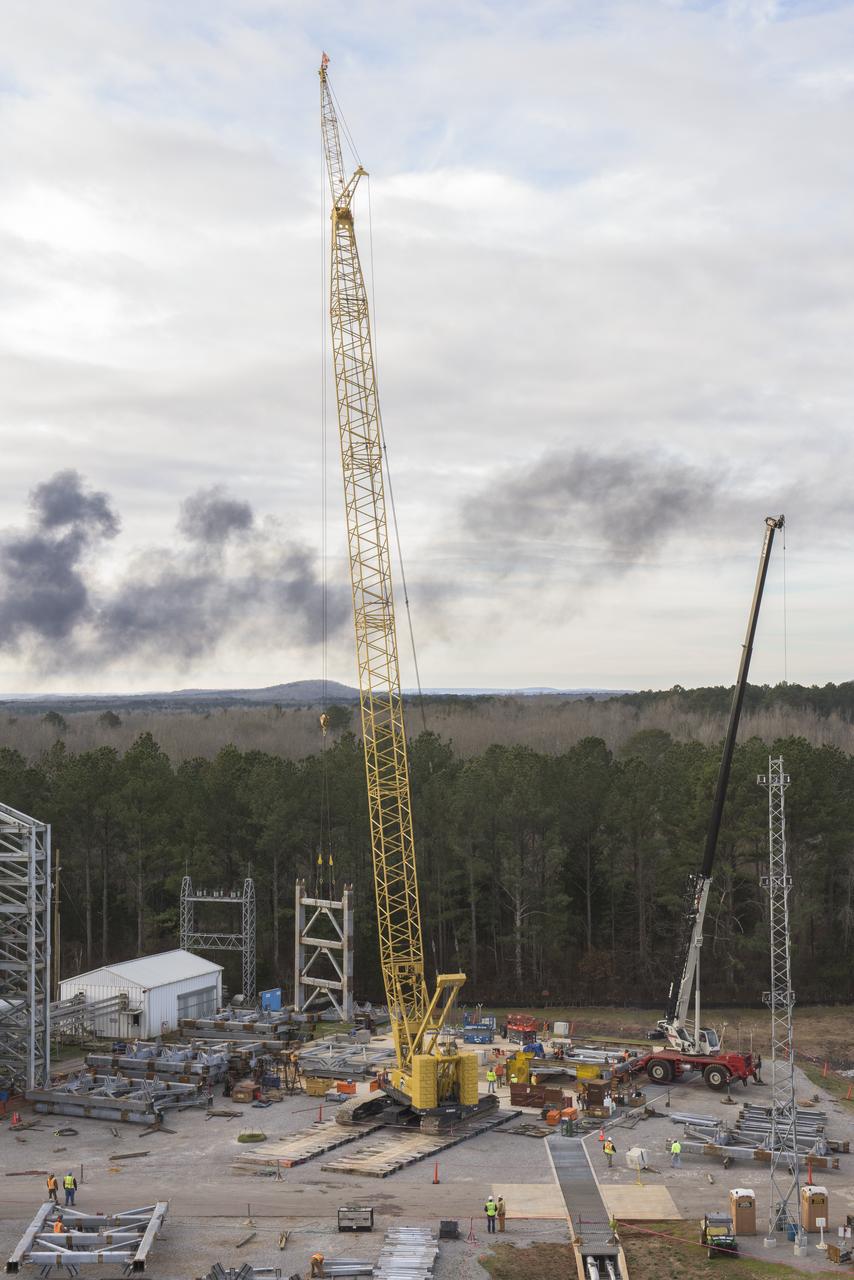
A CRANE MOVES THE FIRST STEEL TIER TO BE BOLTED INTO PLACE ON JAN. 6, FOR WELDING OF A SECOND NEW STRUCTURAL TEST STAND AT NASA'S MARSHALL SPACE FLIGHT CENTER IN HUNTSVILLE, ALABAMA -- CRITICAL TO DEVELOPMENT OF NASA'S SPACE LAUNCH SYSTEM. WHEN COMPLETED THIS SUMMER, THE 85-FOOT-TALL TEST STAND 4697 WILL USE HYDRAULIC CYLINDERS TO SUBJECT THE LIQUID OXYGEN TANK AND HARDWARE OF THE MASSIVE SLS CORE STAGE TO THE SAME LOADS AND STRESSES IT WILL ENDURE DURING A LAUNCH. THE STAND IS RISING IN MARSHALL'S WEST TEST AREA, WHERE WORK IS ALSO UNDERWAY ON THE 215-FOOT-TALL TOWERS OF TEST STAND 4693, WHICH WILL CONDUCT SIMILAR STRUCTURAL TESTS ON THE SLS CORE STAGE'S LIQUID HYDROGEN TANK. SLS, THE MOST POWERFUL ROCKET EVER BUILT, WILL CARRY ASTRONAUTS IN NASA'S ORION SPACECRAFT ON DEEP SPACE MISSIONS, INCLUDING THE JOURNEY TO MARS.
A CRANE MOVES THE FIRST STEEL TIER TO BE BOLTED INTO PLACE ON JAN. 6, FOR WELDING OF A SECOND NEW STRUCTURAL TEST STAND AT NASA'S MARSHALL SPACE FLIGHT CENTER IN HUNTSVILLE, ALABAMA -- CRITICAL TO DEVELOPMENT OF NASA'S SPACE LAUNCH SYSTEM. WHEN COMPLETED THIS SUMMER, THE 85-FOOT-TALL TEST STAND 4697 WILL USE HYDRAULIC CYLINDERS TO SUBJECT THE LIQUID OXYGEN TANK AND HARDWARE OF THE MASSIVE SLS CORE STAGE TO THE SAME LOADS AND STRESSES IT WILL ENDURE DURING A LAUNCH. THE STAND IS RISING IN MARSHALL'S WEST TEST AREA, WHERE WORK IS ALSO UNDERWAY ON THE 215-FOOT-TALL TOWERS OF TEST STAND 4693, WHICH WILL CONDUCT SIMILAR STRUCTURAL TESTS ON THE SLS CORE STAGE'S LIQUID HYDROGEN TANK. SLS, THE MOST POWERFUL ROCKET EVER BUILT, WILL CARRY ASTRONAUTS IN NASA'S ORION SPACECRAFT ON DEEP SPACE MISSIONS, INCLUDING THE JOURNEY TO MARS.
A CRANE MOVES THE FIRST STEEL TIER TO BE BOLTED INTO PLACE ON JAN. 6, FOR WELDING OF A SECOND NEW STRUCTURAL TEST STAND AT NASA'S MARSHALL SPACE FLIGHT CENTER IN HUNTSVILLE, ALABAMA -- CRITICAL TO DEVELOPMENT OF NASA'S SPACE LAUNCH SYSTEM. WHEN COMPLETED THIS SUMMER, THE 85-FOOT-TALL TEST STAND 4697 WILL USE HYDRAULIC CYLINDERS TO SUBJECT THE LIQUID OXYGEN TANK AND HARDWARE OF THE MASSIVE SLS CORE STAGE TO THE SAME LOADS AND STRESSES IT WILL ENDURE DURING A LAUNCH. THE STAND IS RISING IN MARSHALL'S WEST TEST AREA, WHERE WORK IS ALSO UNDERWAY ON THE 215-FOOT-TALL TOWERS OF TEST STAND 4693, WHICH WILL CONDUCT SIMILAR STRUCTURAL TESTS ON THE SLS CORE STAGE'S LIQUID HYDROGEN TANK. SLS, THE MOST POWERFUL ROCKET EVER BUILT, WILL CARRY ASTRONAUTS IN NASA'S ORION SPACECRAFT ON DEEP SPACE MISSIONS, INCLUDING THE JOURNEY TO MARS.
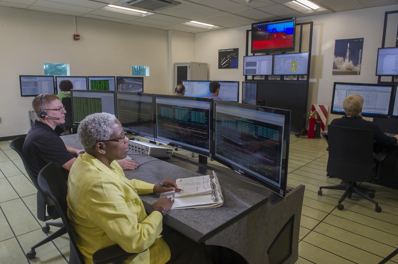
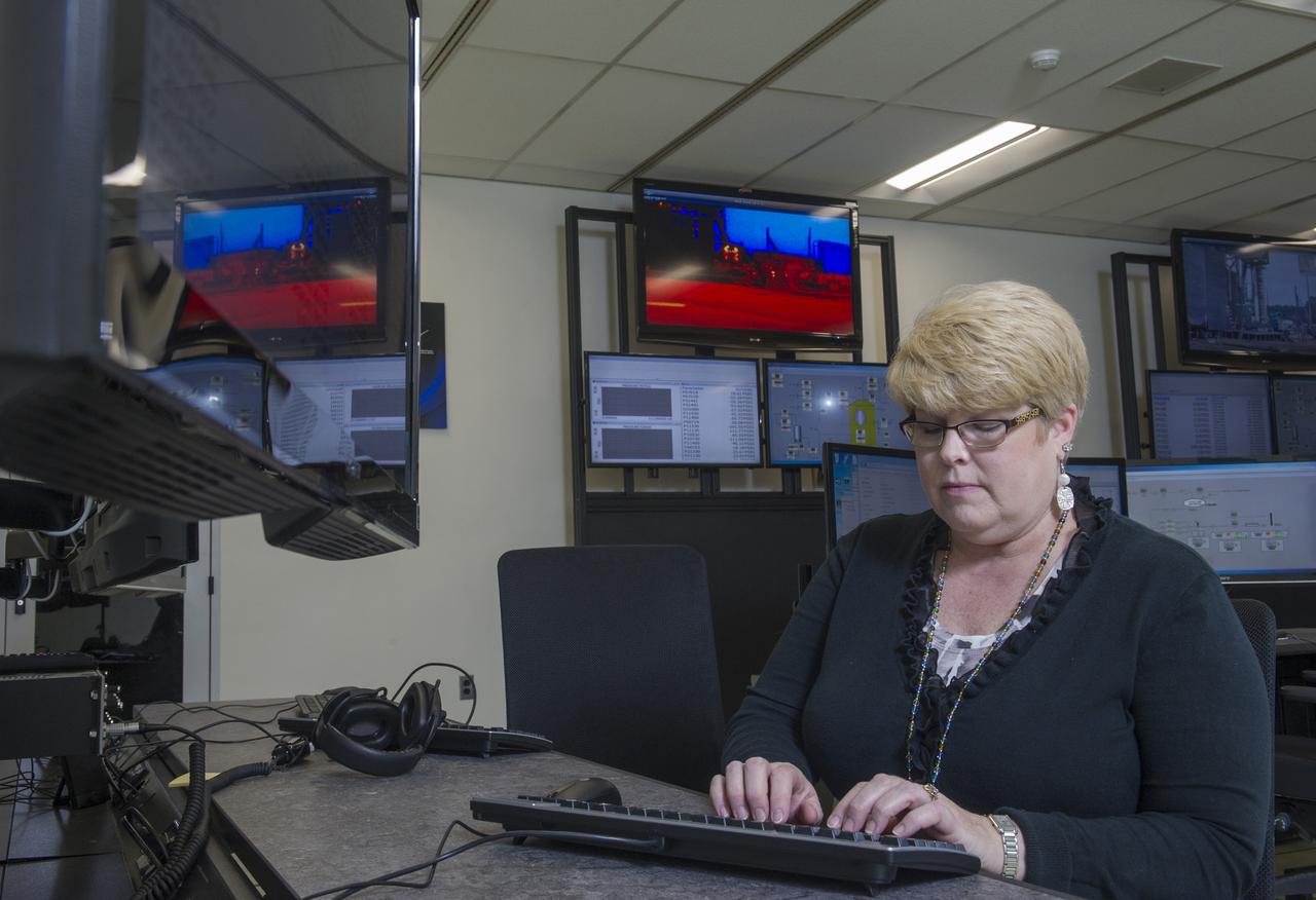
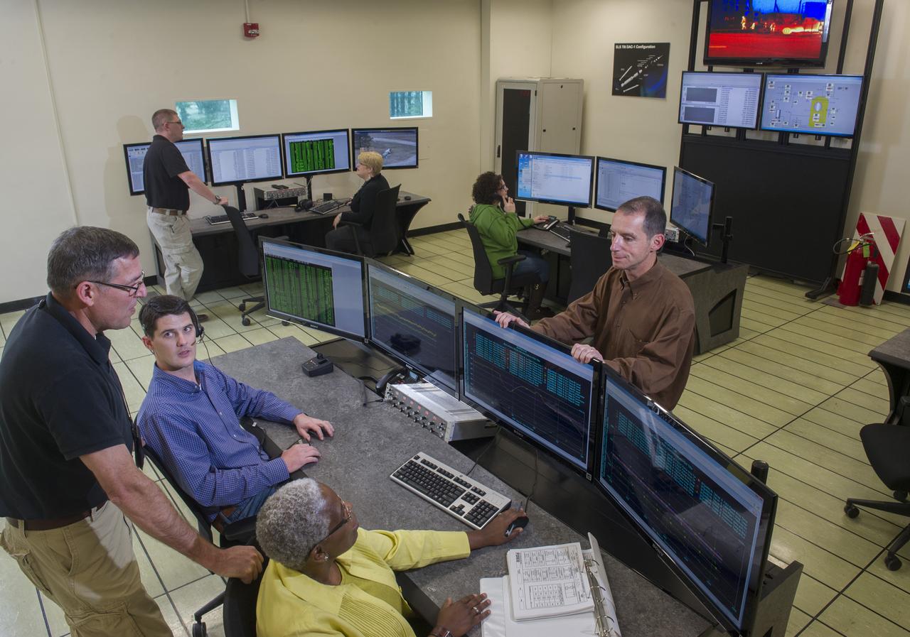
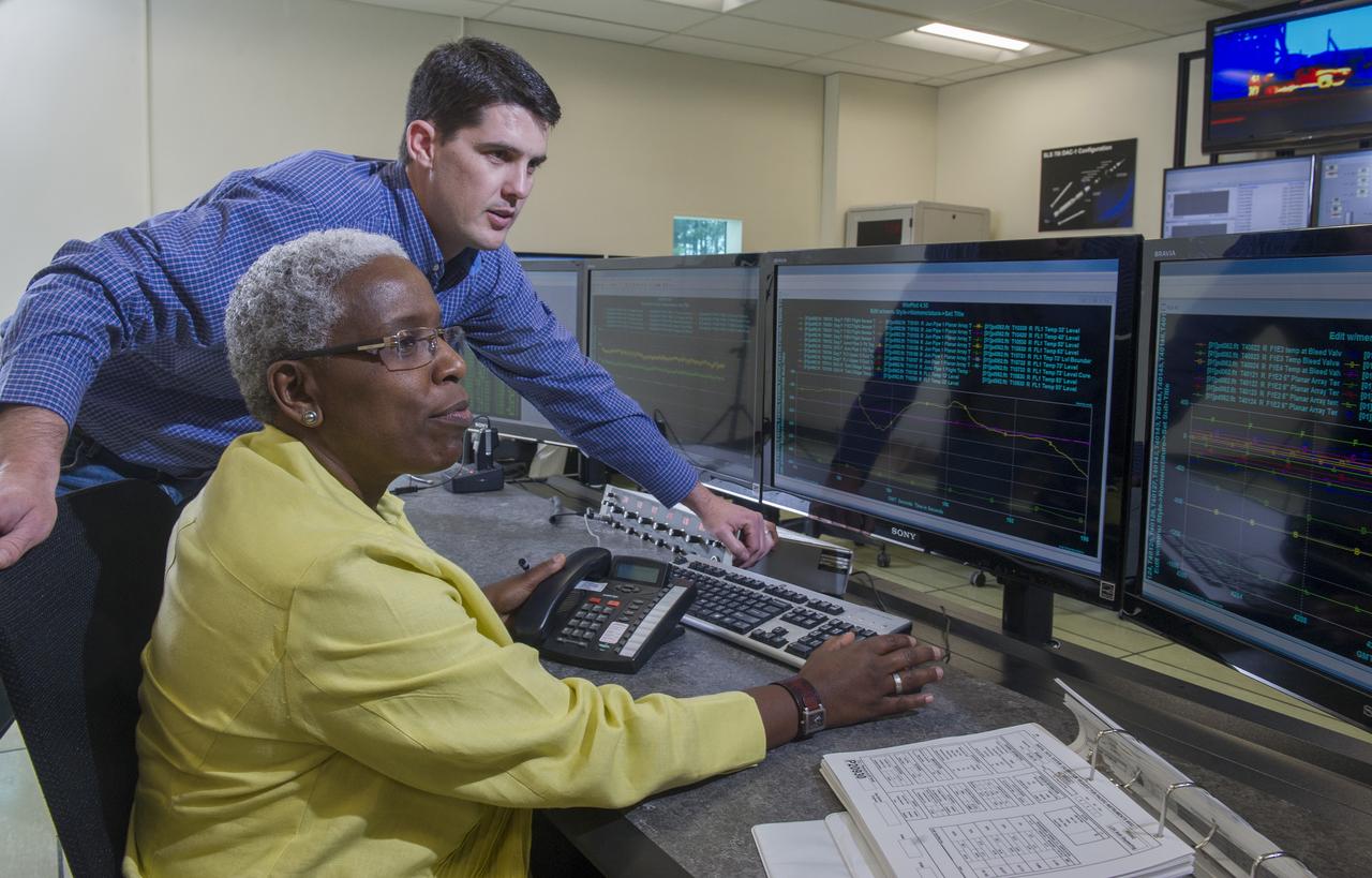
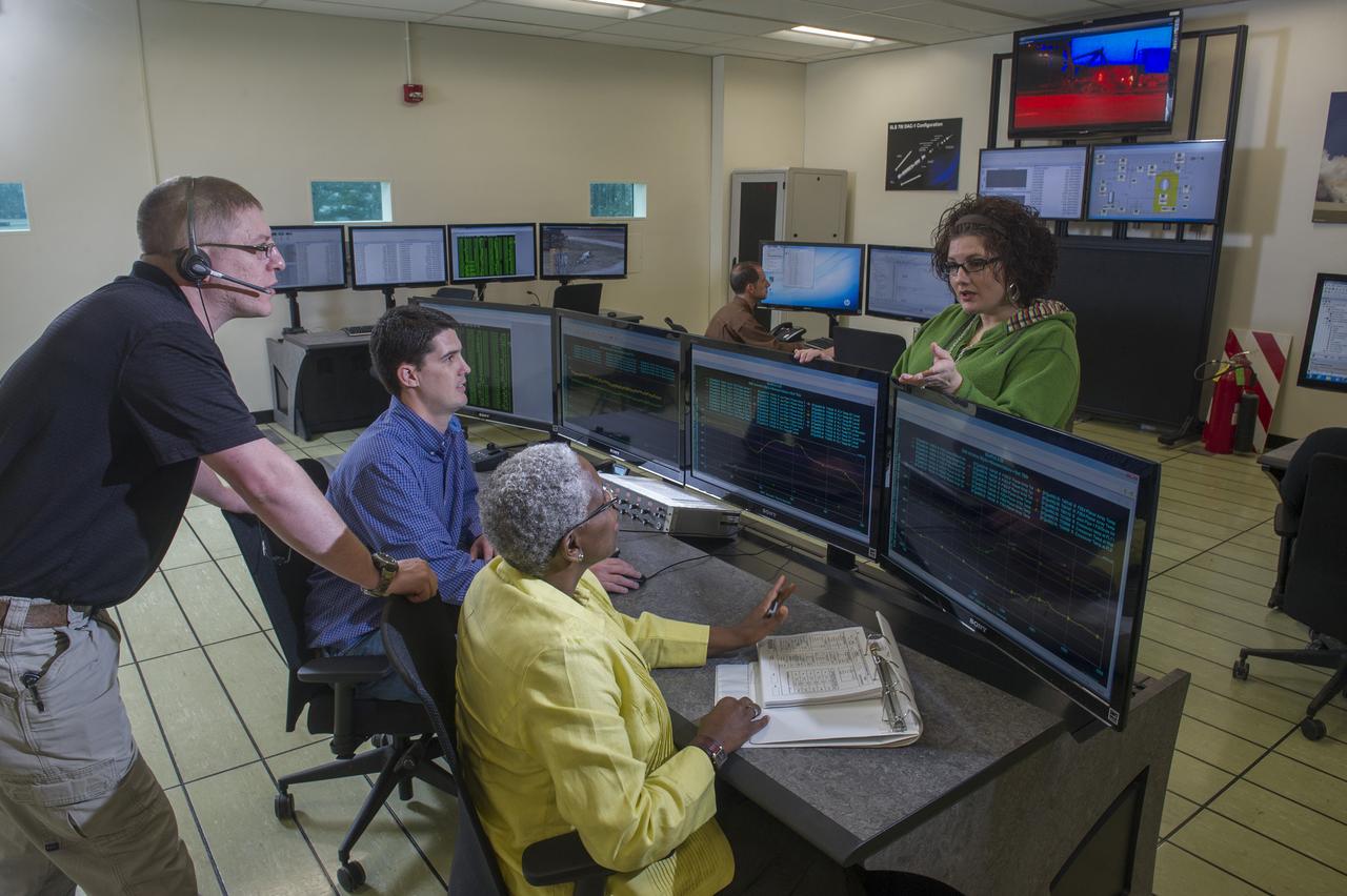
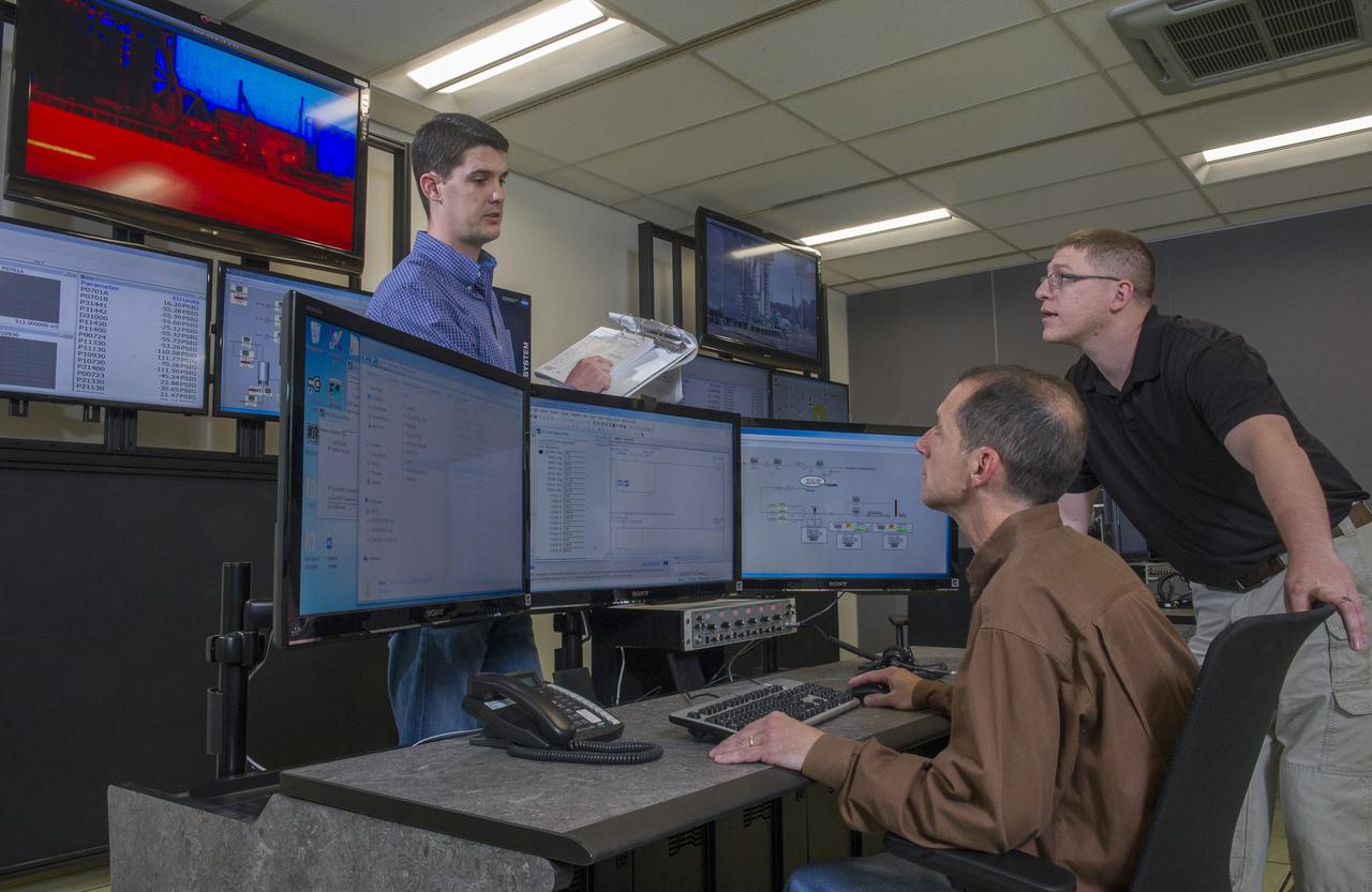
STEVEN SPRAYBERRY, ALICE DANIEL, CHRISTY BASHMAN, ALLEN SHELTON, BEVERELY COURREGE, MATHEW EXELL, JIM EMMENEGGER, IN VARIOUS SETUPS AT WEST TEST AREA CONTROL ROOM-B.
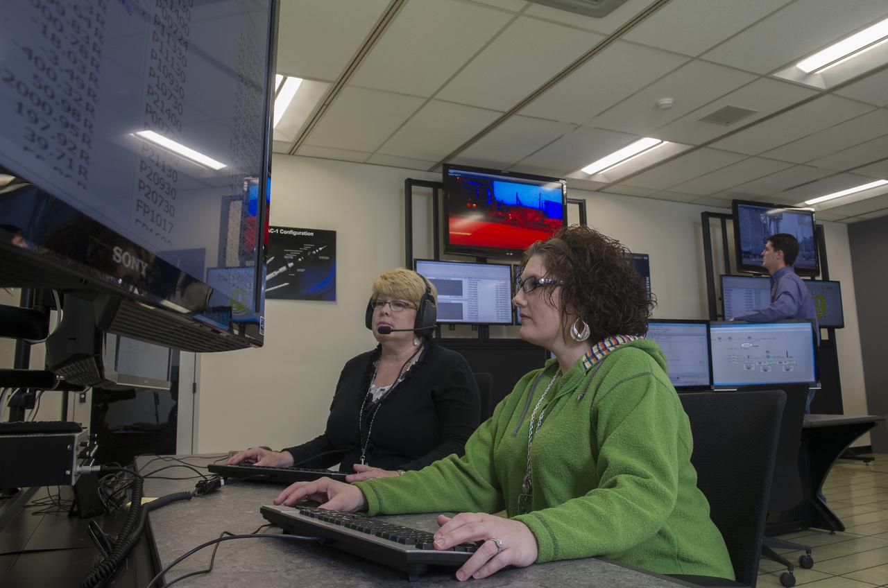
STEVEN SPRAYBERRY, ALICE DANIEL, CHRISTY BASHMAN, ALLEN SHELTON, BEVERELY COURREGE, MATHEW EXELL, JIM EMMENEGGER, IN VARIOUS SETUPS AT WEST TEST AREA CONTROL ROOM-B.
STEVEN SPRAYBERRY, ALICE DANIEL, CHRISTY BASHMAN, ALLEN SHELTON, BEVERELY COURREGE, MATHEW EXELL, JIM EMMENEGGER, IN VARIOUS SETUPS AT WEST TEST AREA CONTROL ROOM-B.
STEVEN SPRAYBERRY, ALICE DANIEL, CHRISTY BASHMAN, ALLEN SHELTON, BEVERELY COURREGE, MATHEW EXELL, JIM EMMENEGGER, IN VARIOUS SETUPS AT WEST TEST AREA CONTROL ROOM-B.
STEVEN SPRAYBERRY, ALICE DANIEL, CHRISTY BASHMAN, ALLEN SHELTON, BEVERELY COURREGE, MATHEW EXELL, JIM EMMENEGGER, IN VARIOUS SETUPS AT WEST TEST AREA CONTROL ROOM-B.
STEVEN SPRAYBERRY, ALICE DANIEL, CHRISTY BASHMAN, ALLEN SHELTON, BEVERELY COURREGE, MATHEW EXELL, JIM EMMENEGGER, IN VARIOUS SETUPS AT WEST TEST AREA CONTROL ROOM-B.
STEVEN SPRAYBERRY, ALICE DANIEL, CHRISTY BASHMAN, ALLEN SHELTON, BEVERELY COURREGE, MATHEW EXELL, JIM EMMENEGGER, IN VARIOUS SETUPS AT WEST TEST AREA CONTROL ROOM-B.
At its founding, the Marshall Space Flight Center (MSFC) inherited the Army’s Jupiter and Redstone test stands, but much larger facilities were needed for the giant stages of the Saturn V. From 1960 to 1964, the existing stands were remodeled and a sizable new test area was developed. The new comprehensive test complex for propulsion and structural dynamics was unique within the nation and the free world, and they remain so today because they were constructed with foresight to meet the future as well as on going needs. Construction of the S-IC Static test stand complex began in 1961 in the west test area of MSFC, and was completed in 1964. The S-IC static test stand was designed to develop and test the 138-ft long and 33-ft diameter Saturn V S-IC first stage, or booster stage, weighing in at 280,000 pounds. Required to hold down the brute force of a 7,500,000-pound thrust produced by 5 F-1 engines, the S-IC static test stand was designed and constructed with the strength of hundreds of tons of steel and 12,000,000 pounds of cement, planted down to bedrock 40 feet below ground level. The foundation walls, constructed with concrete and steel, are 4 feet thick. The base structure consists of four towers with 40-foot-thick walls extending upward 144 feet above ground level. The structure was topped by a crane with a 135-foot boom. With the boom in the upright position, the stand was given an overall height of 405 feet, placing it among the highest structures in Alabama at the time. In addition to the stand itself, related facilities were constructed during this time. Built to the northeast of the stand was a newly constructed Pump House. Its function was to provide water to the stand to prevent melting damage during testing. The water was sprayed through small holes in the stand’s 1900 ton flame deflector at the rate of 320,000 gallons per minute. This close up photograph, taken September 5, 1963, shows the ground level frame work for the Pump House and its massive round water storage tanks.
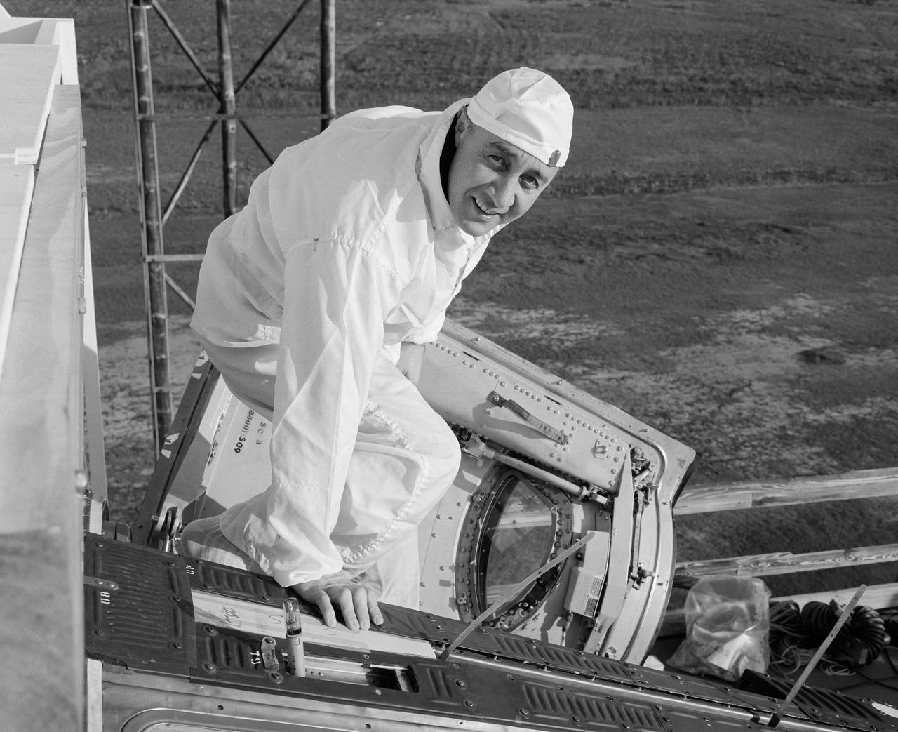
S65-13243 (6 Jan. 1965) --- Astronaut Virgil I. Grissom, Gemini-Titan 3 command pilot, is shown entering the Gemini-3 spacecraft for a communications test at the Merritt Island launch area.
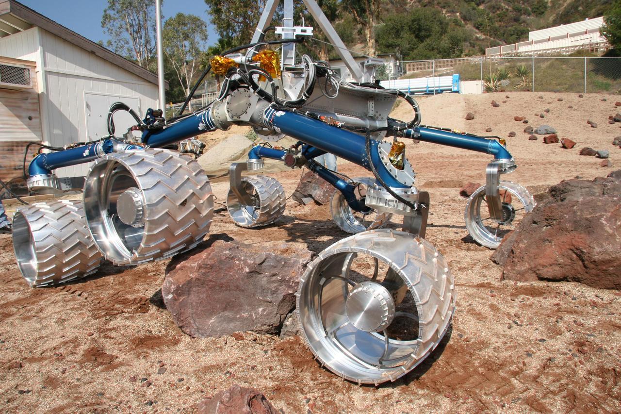
Scarecrow, a mobility-testing model for NASA Mars Science Laboratory, easily traverses large rocks in the Mars Yard testing area at NASA Jet Propulsion Laboratory.
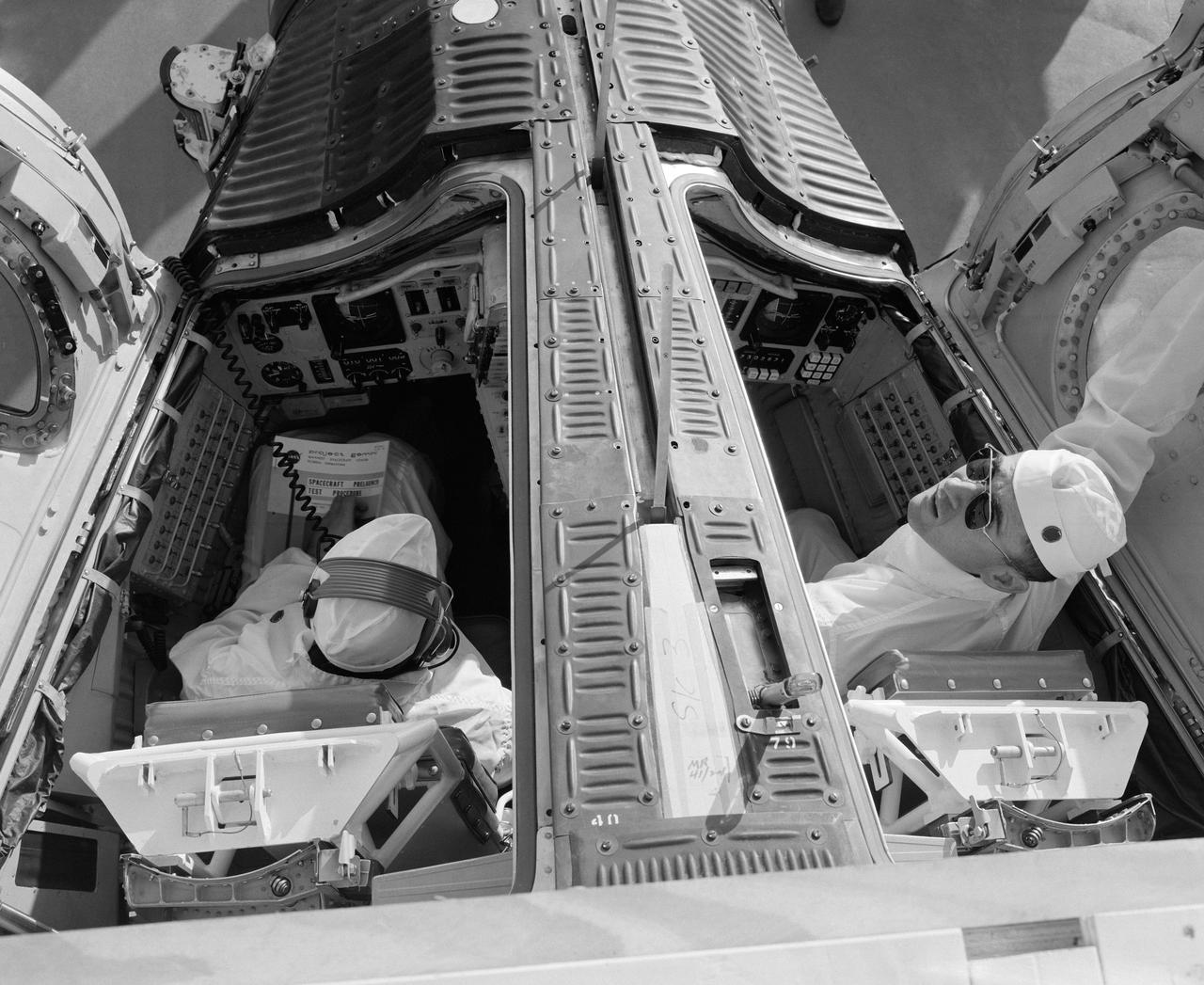
S65-13244 (6 Jan. 1965) --- The Gemini-Titan 3 prime crew, astronauts Virgil I. Grissom (left) and John W. Young, are shown in the Gemini-3 spacecraft during a communications test at the Merritt Island launch area.

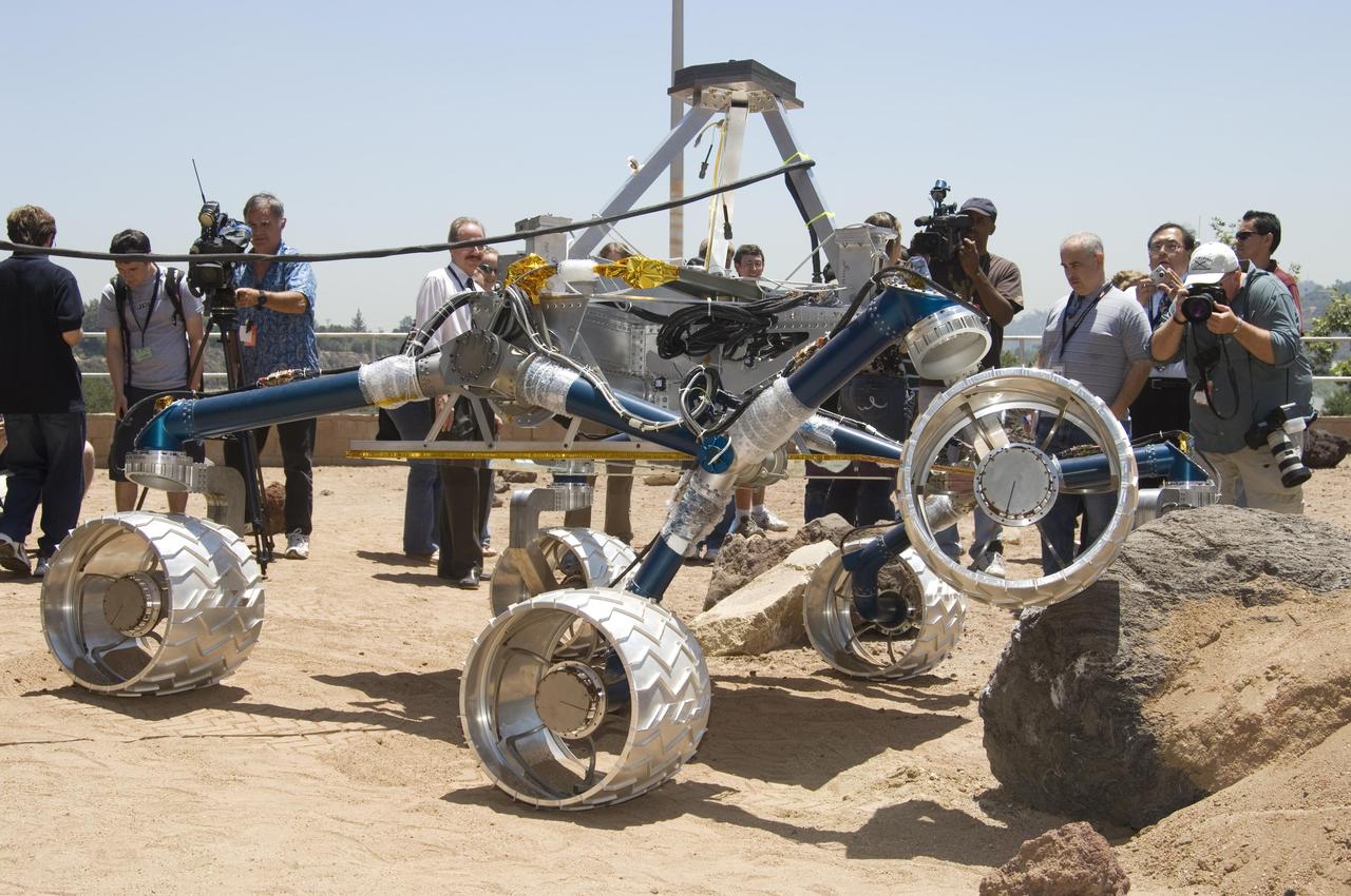
This grouping of two test rovers and a flight spare provides a graphic comparison of three generations of Mars rovers developed at NASA Jet Propulsion Laboratory, Pasadena, Calif. The setting is JPL Mars Yard testing area.
Onlookers watch as Scarecrow, a mobility-testing model for NASA Mars Science Laboratory, easily conquers boulders in the Mars Yard testing area at NASA Jet Propulsion Laboratory.

This grouping of two test rovers and a flight spare provides a graphic comparison of three generations of Mars rovers developed at NASA Jet Propulsion Laboratory, Pasadena, Calif. The setting is JPL Mars Yard testing area.
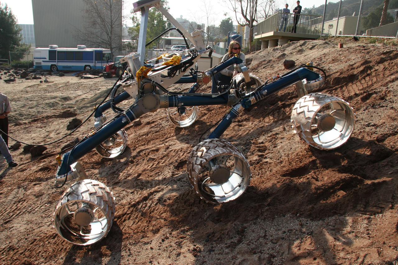
An engineering model for NASA Mars Science Laboratory makes its way up a hill in the Mars Yard testing area at NASA Jet Propulsion Laboratory.
Aerial photograph of MSFC test stand 4693 with the Liquid Hydrogen test article (LH2) in the stand

Aerial photograph of MSFC test stand 4693 with the Liquid Hydrogen test article (LH2) in the stand

THE GAS GENERATOR TO AN F-1 ENGINE, THE MOST POWERFUL ROCKET ENGINE EVER BUILT, IS TEST-FIRED AT NASA'S MARSHALL SPACE FLIGHT CENTER IN HUNTSVILLE, ALABAMA, ON SEPT. 3. ALTHOUGH THE ENGINE WAS ORIGINALLY BUILT TO POWER THE SATURN V ROCKETS DURING AMERICA'S MISSIONS TO THE MOON, THIS TEST ARTICLE HAD NEW PARTS CREATED USING ADDITIVE MANUFACTURING, OR 3-D PRINTING, TO TEST THE VIABILITY OF THE TECHNOLOGY FOR BUILDING NEW ENGINE DESIGNS.
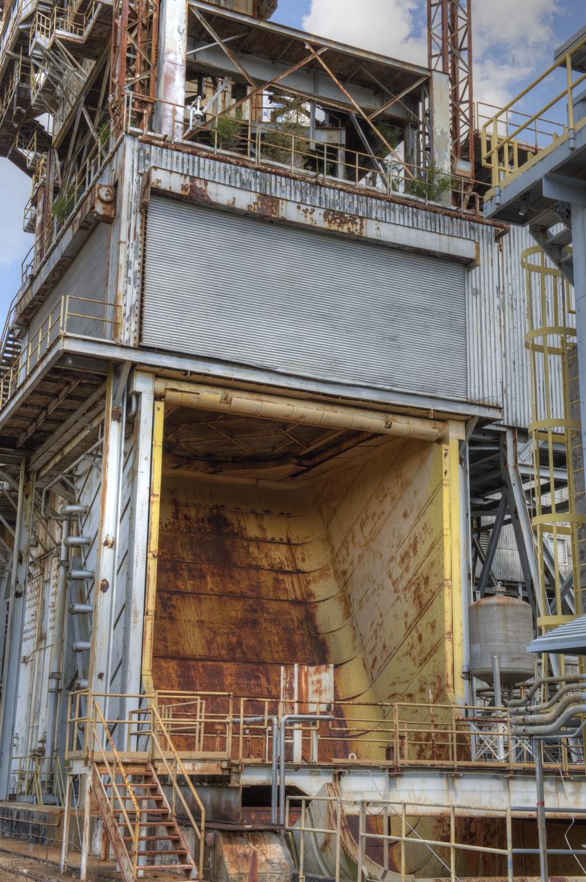
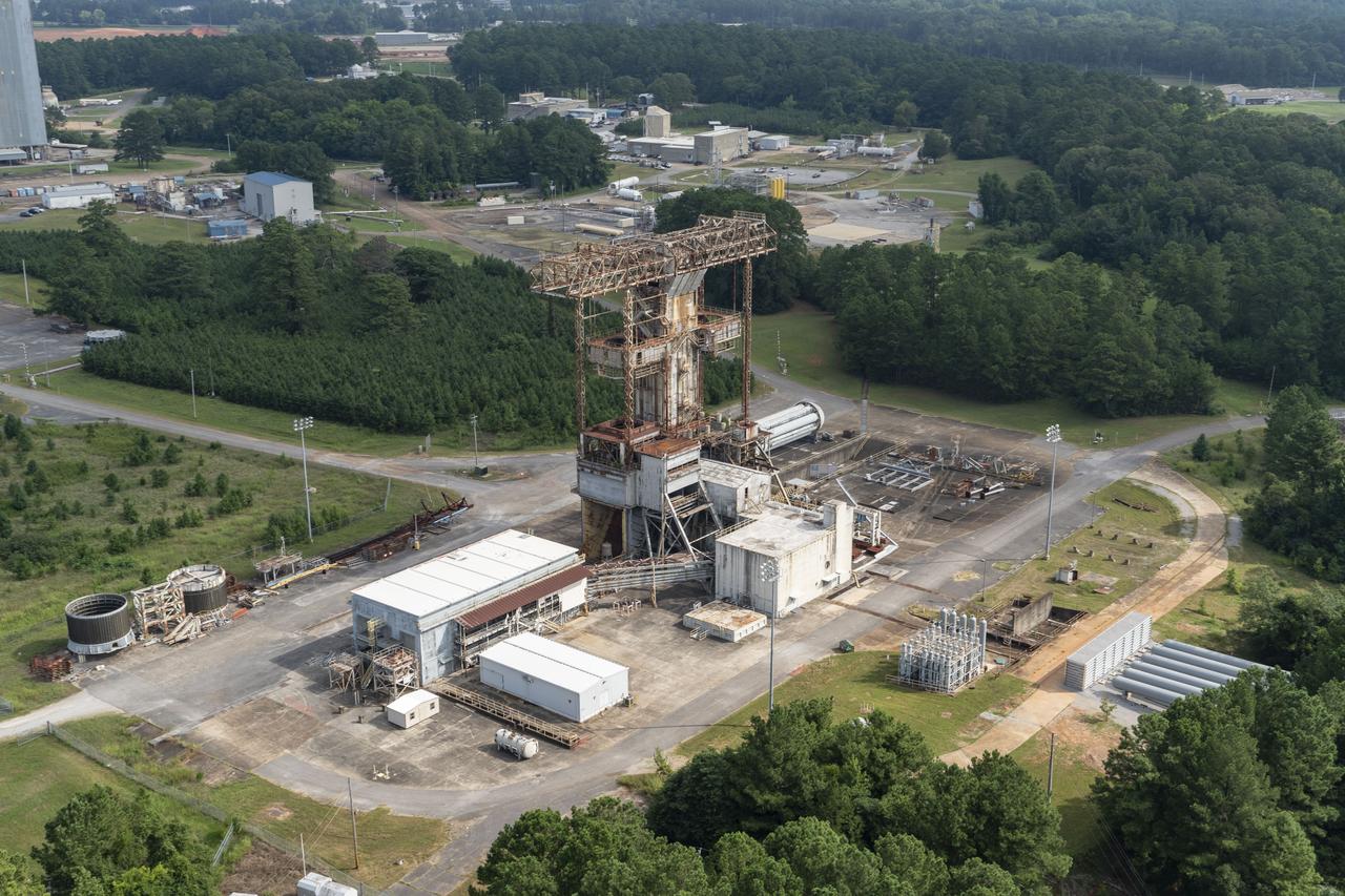
PROPULSION AND STRUCTURAL TEST FACILITY (BUILDING 4572) AT THE GEORGE C. MARSHALL SPACE FLIGHT CENTER IN HUNTSVILLE, ALABAMA
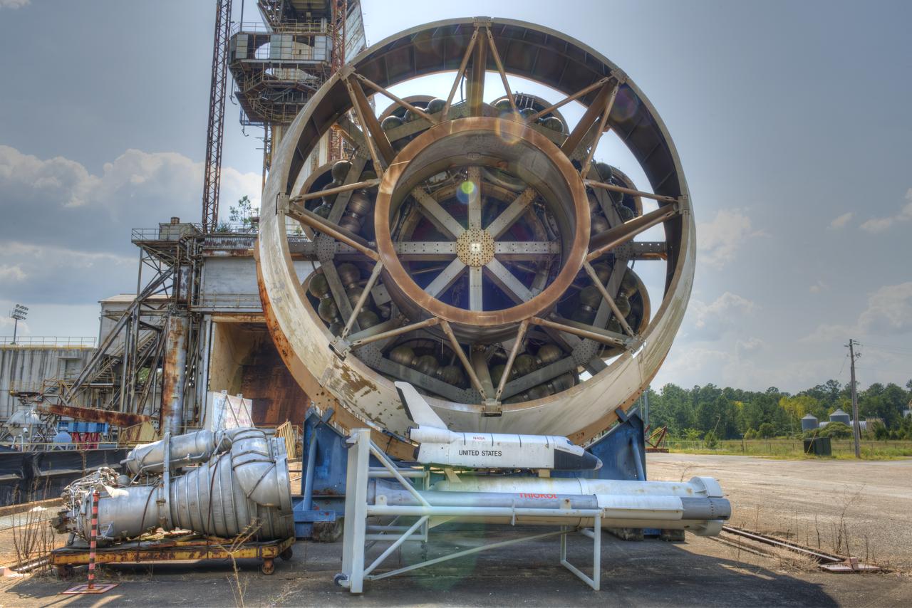
FORWARD END OF SATURN S-1B STAGE (SA-T) NEAR PROPULSION AND STRUCTURAL TEST FACILITY (BUILDING 4572) AT THE GEORGE C. MARSHALL SPACE FLIGHT CENTER IN HUNTSVILLE, ALABAMA
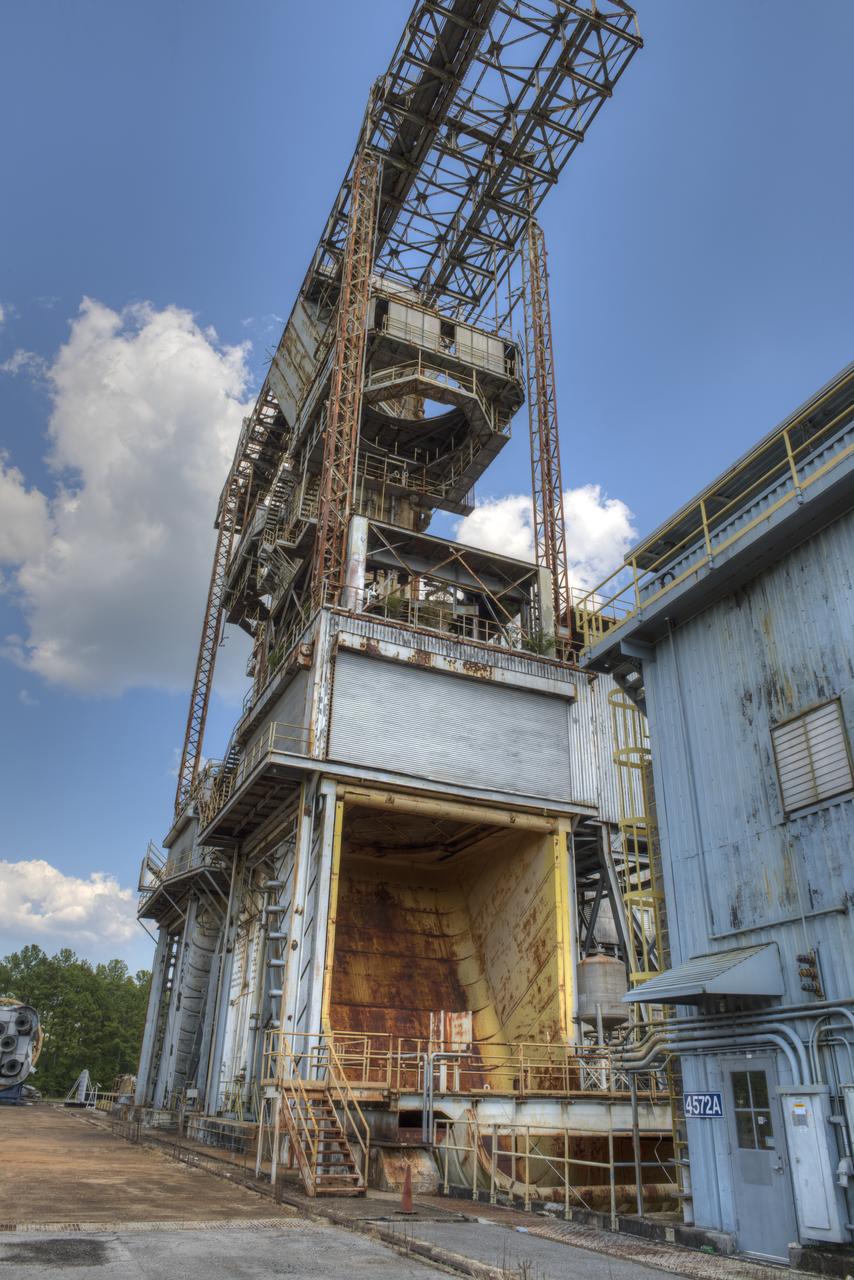
PROPULSION AND STRUCTURAL TEST FACILITY (BUILDING 4572) AT THE GEORGE C. MARSHALL SPACE FLIGHT CENTER IN HUNTSVILLE, ALABAMA
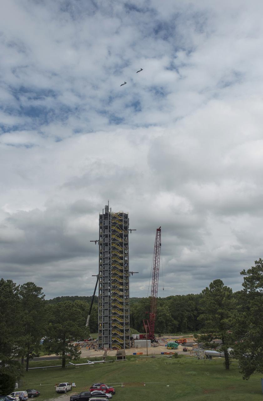
ASTRONAUTS BARRY "BUTCH” WILMORE, VICTOR GLOVER, DON PETTIT AND STEPHANIE WILSON SOAR ABOVE TEST STAND 4693 IN #NASA T-38 JETS ON AUG. 9, 2016
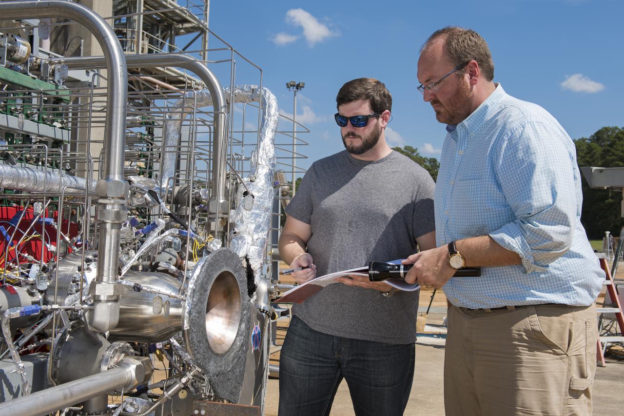
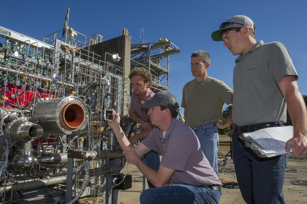
Graham Nelson, right, and Andrew Hanks examine a combustion chamber developed by engineers at NASA's Marshall Space Flight Center in Huntsville, Alabama, for an additively manufactured demonstration breadboard engine project. Nelson is project manager and Hanks is test lead for the project, in which engineers are designing components from scratch to be made entirely by 3-D printing.
PROPULSION AND STRUCTURAL TEST FACILITY (BUILDING 4572) AT THE GEORGE C. MARSHALL SPACE FLIGHT CENTER IN HUNTSVILLE, ALABAMA

THE GAS GENERATOR TO AN F-1 ENGINE, THE MOST POWERFUL ROCKET ENGINE EVER BUILT, IS TEST-FIRED AT NASA'S MARSHALL SPACE FLIGHT CENTER IN HUNTSVILLE, ALABAMA, ON SEPT. 3. ALTHOUGH THE ENGINE WAS ORIGINALLY BUILT TO POWER THE SATURN V ROCKETS DURING AMERICA'S MISSIONS TO THE MOON, THIS TEST ARTICLE HAD NEW PARTS CREATED USING ADDITIVE MANUFACTURING, OR 3-D PRINTING, TO TEST THE VIABILITY OF THE TECHNOLOGY FOR BUILDING NEW ENGINE DESIGNS.
PROPULSION AND STRUCTURAL TEST FACILITY (BUILDING 4572) AT THE GEORGE C. MARSHALL SPACE FLIGHT CENTER IN HUNTSVILLE, ALABAMA
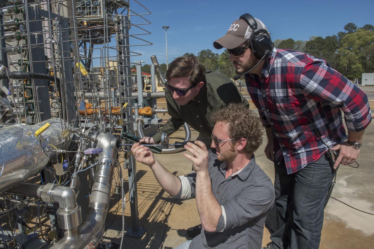
ENGINEERS PREPARE 3-D PRINTED TURBOPUMP FOR A TEST AT NASA’S MARSHALL SPACE FLIGHT CENTER IN HUNTSVILLE, ALABAMA. THE TURBOPUMP WAS TESTED AT FULL POWER, PUMPING 600 GALLONS OF LIQUID METHANE PER MINUTE, ENOUGH TO POWER AN ENGINE CAPABLE OF GENERATING 35,000 POUNDS OF THRUST…NICK CASE, (GREEN SHIRT), ANDREW HANKS, (PLAID SHIRT), MARTY CALVERT (KNEELING)

THE GAS GENERATOR TO AN F-1 ENGINE, THE MOST POWERFUL ROCKET ENGINE EVER BUILT, IS TEST-FIRED AT NASA'S MARSHALL SPACE FLIGHT CENTER IN HUNTSVILLE, ALABAMA, ON SEPT. 3. ALTHOUGH THE ENGINE WAS ORIGINALLY BUILT TO POWER THE SATURN V ROCKETS DURING AMERICA'S MISSIONS TO THE MOON, THIS TEST ARTICLE HAD NEW PARTS CREATED USING ADDITIVE MANUFACTURING, OR 3-D PRINTING, TO TEST THE VIABILITY OF THE TECHNOLOGY FOR BUILDING NEW ENGINE DESIGNS.
PROPULSION AND STRUCTURAL TEST FACILITY (BUILDING 4572) AT THE GEORGE C. MARSHALL SPACE FLIGHT CENTER IN HUNTSVILLE, ALABAMA WITH THE SATURN S-1B STAGE (SA-) IN FOREGROUND
ASSEMBLING AND TESTING A BREADBOARD ENGINE MADE UP OF 3-D ENGINE COMPONENTS, PROPULSION ENGINEER NICK CASE (LEFT FRONT) PHOTOGRAPHS THE INJECTOR, WHILE RYAN WALLS (FAR RIGHT), THE TEST CONDUCTOR LOOKS ON. MARTY CALVERT (LEFT BACK) AND BRAD BULLARD (RIGHT BACK) HELPED DESIGN THE TURBOPUMP AND INJECTOR, TWO OF THE MOST COMPLEX ENGINE PARTS TESTED.
PROPULSION AND STRUCTURAL TEST FACILITY (BUILDING 4572) AT THE GEORGE C. MARSHALL SPACE FLIGHT CENTER IN HUNTSVILLE, ALABAMA
FORWARD END OF SATURN S-1B STAGE (SA-T) NEAR PROPULSION AND STRUCTURAL TEST FACILITY (BUILDING 4572) AT THE GEORGE C. MARSHALL SPACE FLIGHT CENTER IN HUNTSVILLE, ALABAMA
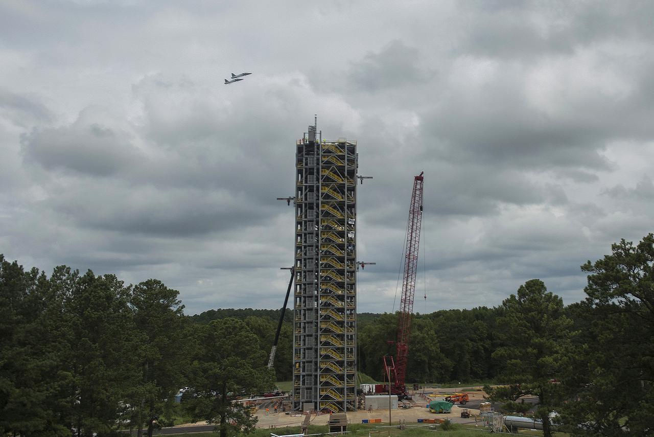
ASTRONAUTS BARRY "BUTCH” WILMORE, VICTOR GLOVER, DON PETTIT AND STEPHANIE WILSON SOAR ABOVE TEST STAND 4693 IN #NASA T-38 JETS ON AUG. 9, 2016
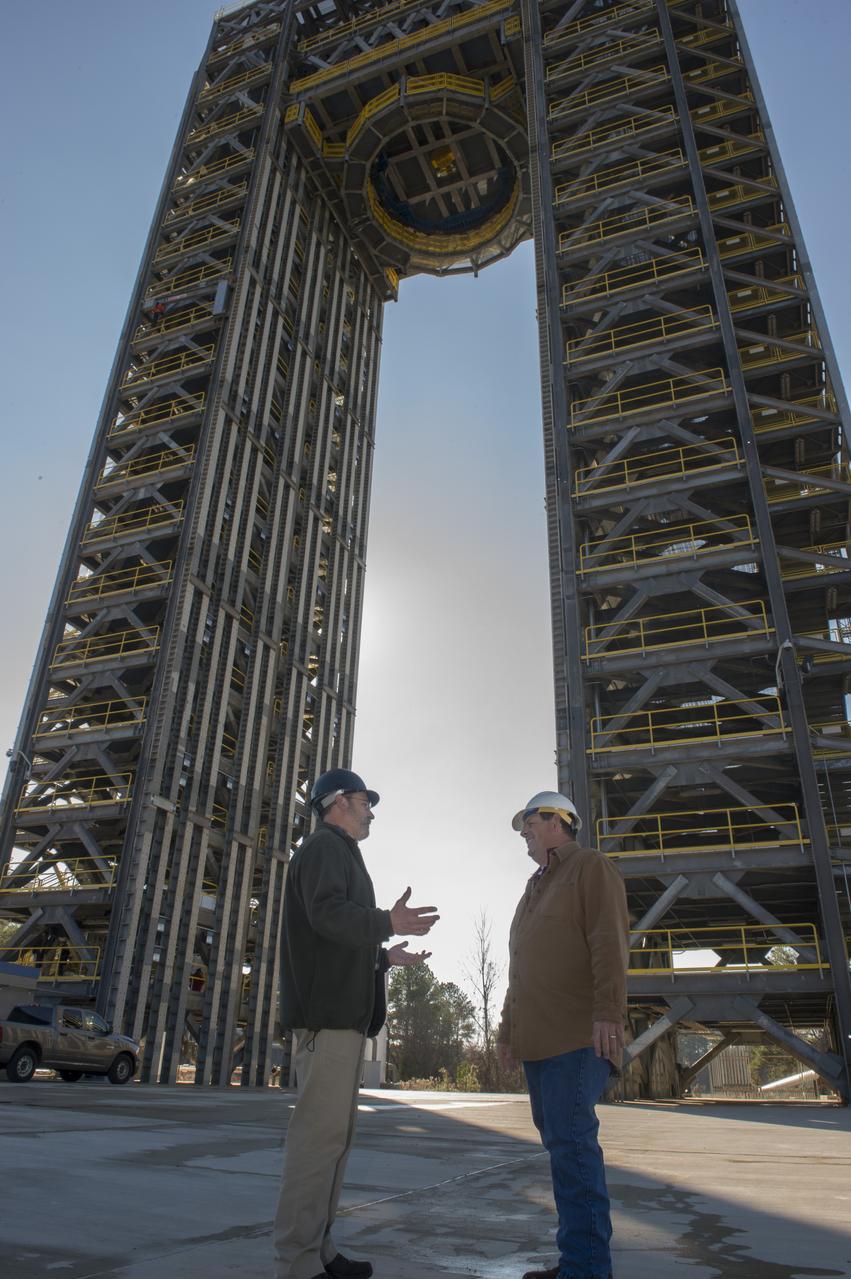
ROBERT BOBO, LEFT, AND MIKE NICHOLS TALK BENEATH THE 221-FOOT-TALL TEST STAND 4693, THE LARGEST OF TWO NEW SPACE LAUNCH SYSTEM TEST STANDS AT MSFC. BOBO MANAGES SLS STRUCTURAL STRENGTH TESTING, AND NICHOLS IS LEAD TEST ENGINEER FOR THE SLS LIQUID HYDROGEN TANK.
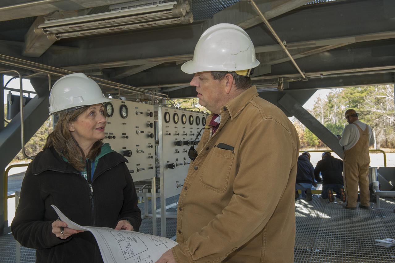
TARA MARSHALL, LEFT, A MARSHALL ENGINEER, TALKS ABOUT THE INSTALLATION OF A PRESSURIZATION CONTROL PANEL AT TEST STAND 4693 WITH MIKE NICHOLS, LEAD TEST ENGINEER FOR THE SPACE LAUNCH SYSTEM LIQUID HYDROGEN TANK STRUCTURAL TEST ARTICLE.
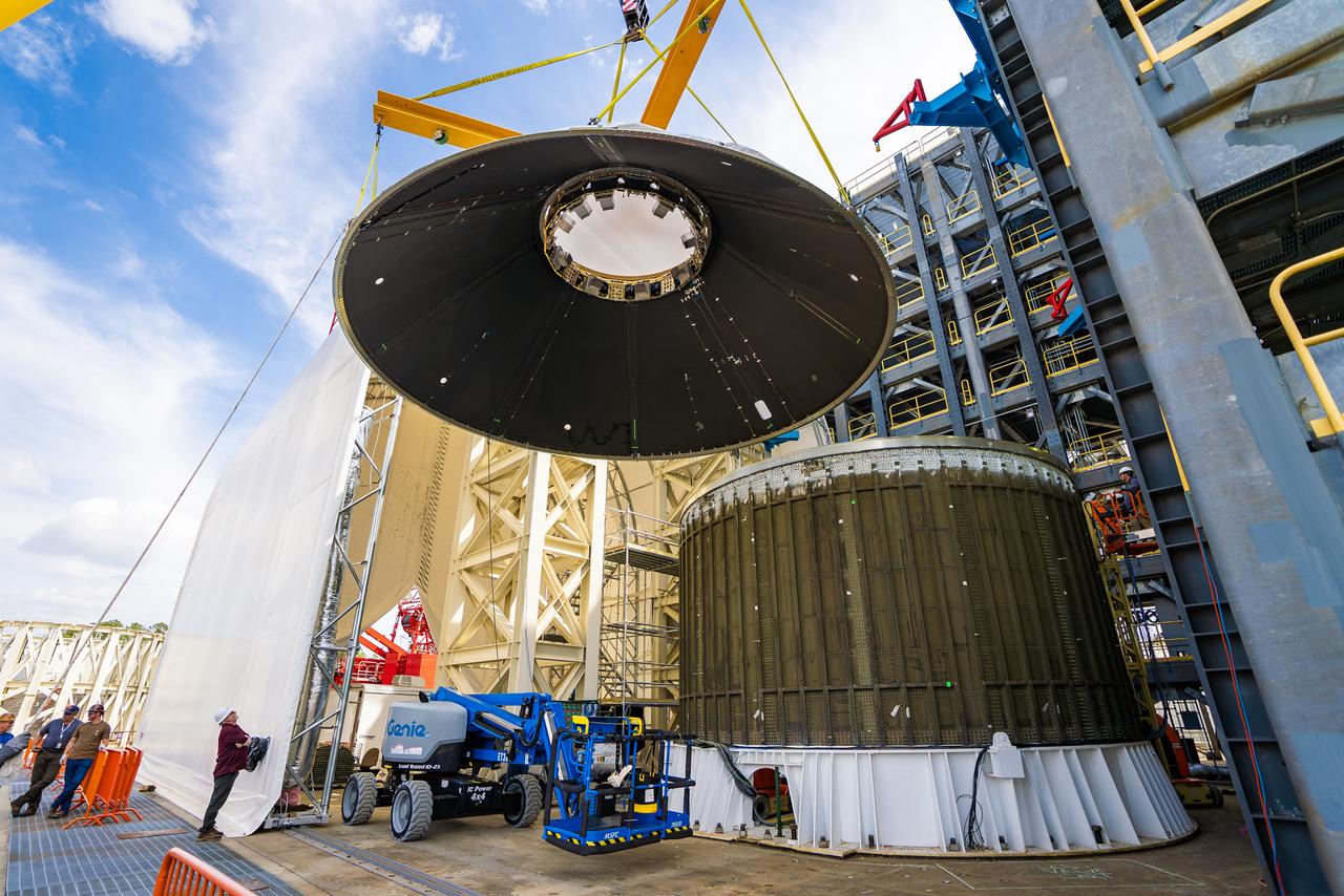
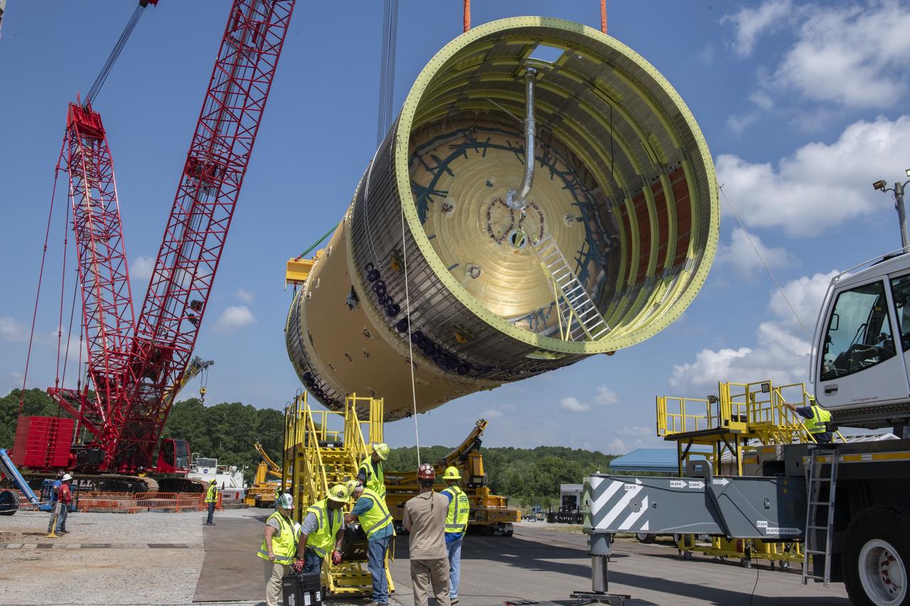
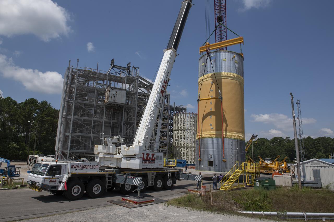
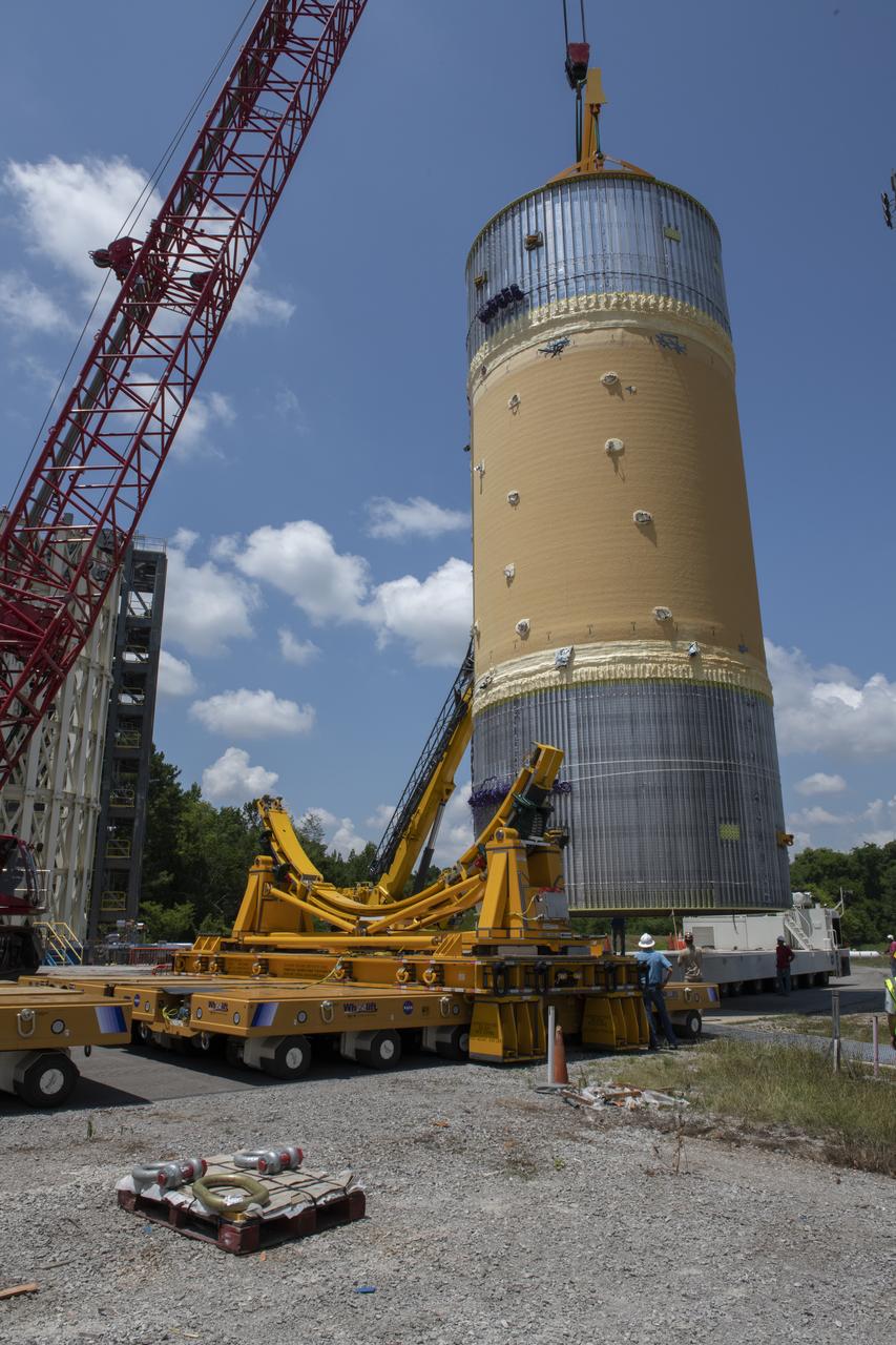
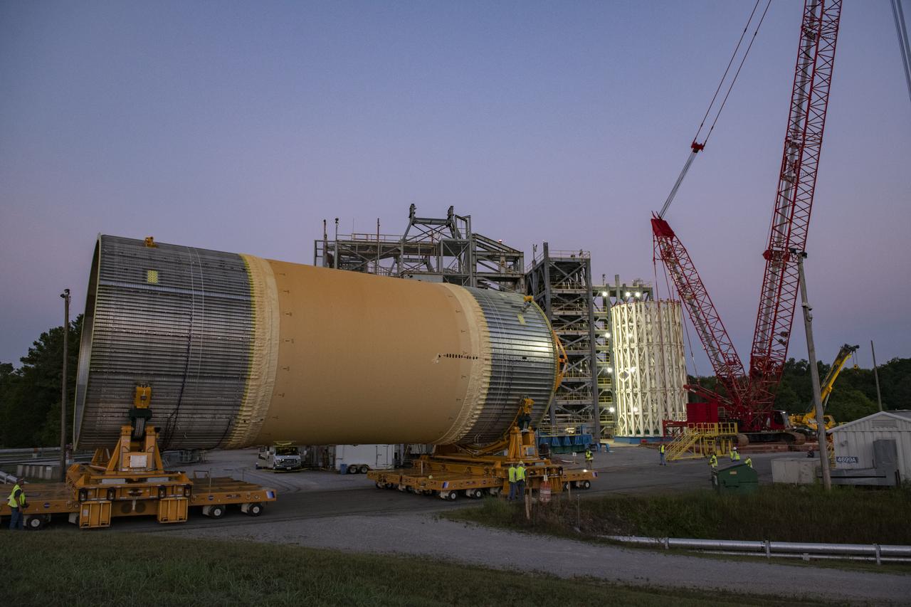
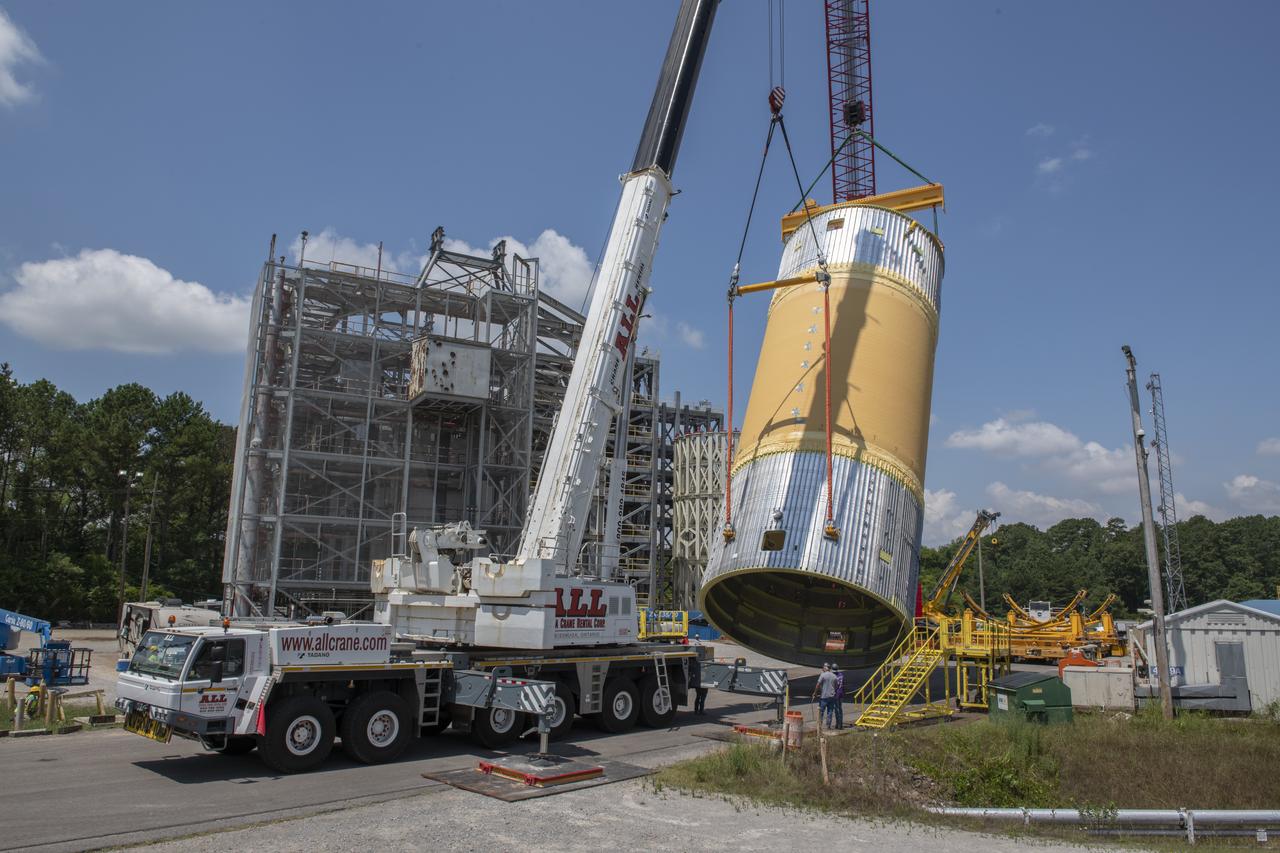
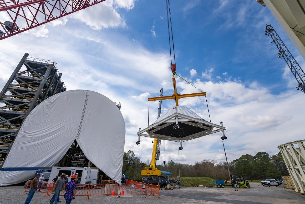
These photos and videos show how crews at NASA’s Marshall Space Flight Center in Huntsville, Alabama, moved and installed the payload adapter that will be used in the Block 1B configuration of the SLS (Space Launch System) rocket from Building 4708, where it was manufactured, into Structural Test Stand 4697 at NASA’s Marshall Space Flight Center on March 13. Teams at Marshall will begin structural testing the engineering development unit of the payload adapter – an exact replica of the flight version of the hardware – this spring. The cone-shaped payload adapter is about 8.5 feet tall and features two metal rings and eight composite panels. The adapter, which will debut on NASA’s Artemis IV mission, is an evolution from the Orion stage adapter used in the Block 1 configuration of the first three Artemis missions. It will be housed inside the universal stage adapter atop the rocket’s more powerful in-space stage, called the exploration upper stage. The payload adapter, like the launch vehicle stage adapter and the Orion stage adapter, is fully manufactured and tested at Marshall, which manages the SLS Program. NASA is working to land the first woman, first person of color, and its first international partner astronaut on the Moon under Artemis. SLS is part of NASA’s backbone for deep space exploration, along with the Orion spacecraft and Gateway in orbit around the Moon and commercial human landing systems, next-generational spacesuits, and rovers on the lunar surface. SLS is the only rocket that can send Orion, astronauts, and supplies to the Moon in a single launch.
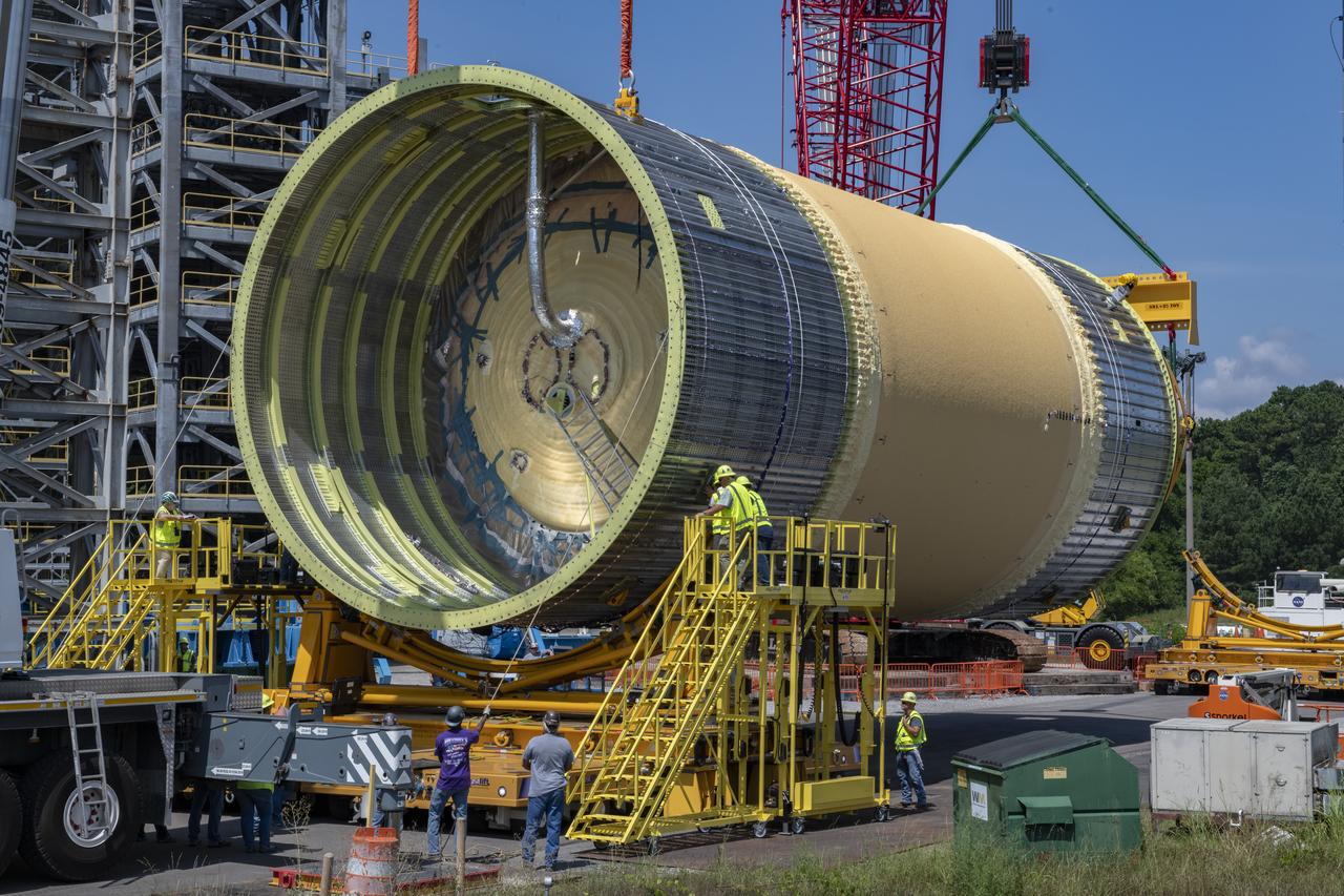
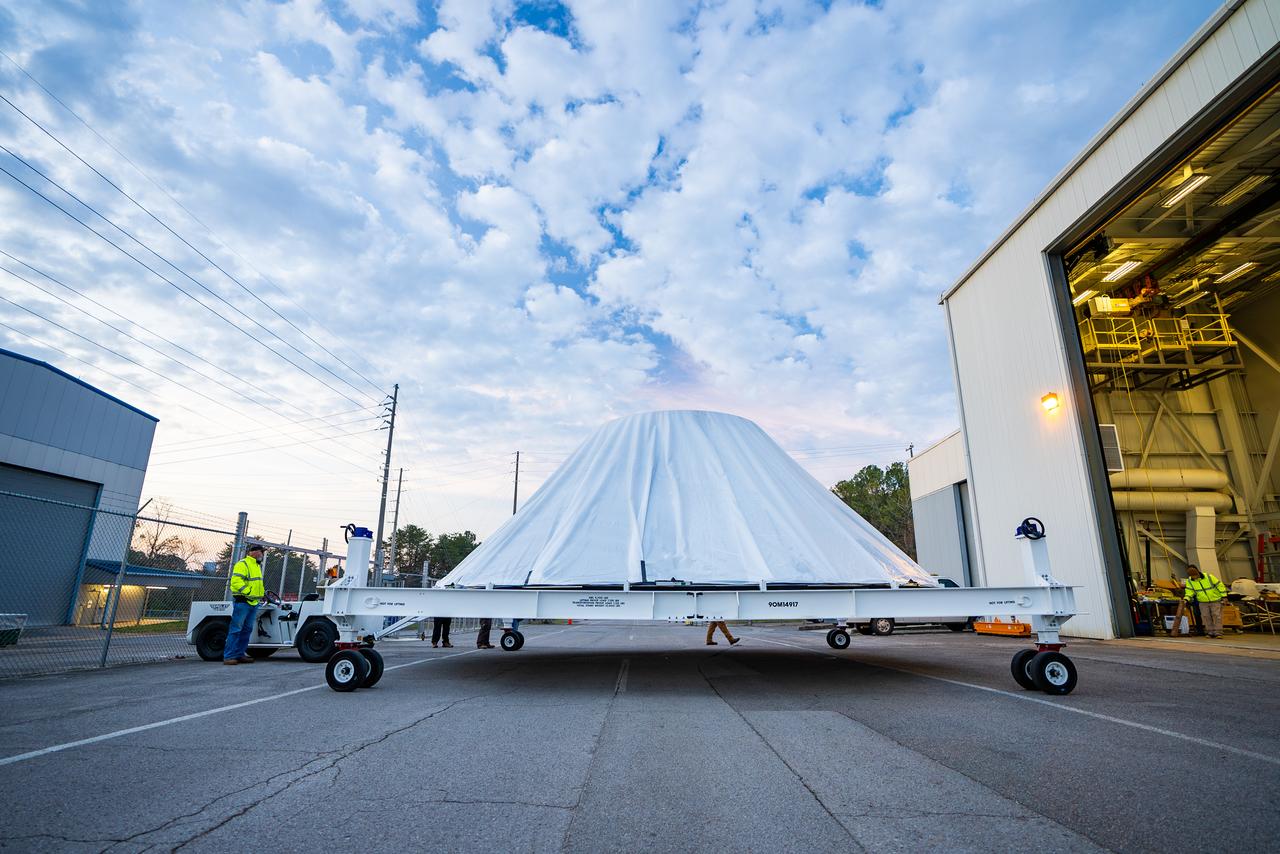
These photos and videos show how crews at NASA’s Marshall Space Flight Center in Huntsville, Alabama, moved and installed the payload adapter that will be used in the Block 1B configuration of the SLS (Space Launch System) rocket from Building 4708, where it was manufactured, into Structural Test Stand 4697 at NASA’s Marshall Space Flight Center on March 13. Teams at Marshall will begin structural testing the engineering development unit of the payload adapter – an exact replica of the flight version of the hardware – this spring. The cone-shaped payload adapter is about 8.5 feet tall and features two metal rings and eight composite panels. The adapter, which will debut on NASA’s Artemis IV mission, is an evolution from the Orion stage adapter used in the Block 1 configuration of the first three Artemis missions. It will be housed inside the universal stage adapter atop the rocket’s more powerful in-space stage, called the exploration upper stage. The payload adapter, like the launch vehicle stage adapter and the Orion stage adapter, is fully manufactured and tested at Marshall, which manages the SLS Program. NASA is working to land the first woman, first person of color, and its first international partner astronaut on the Moon under Artemis. SLS is part of NASA’s backbone for deep space exploration, along with the Orion spacecraft and Gateway in orbit around the Moon and commercial human landing systems, next-generational spacesuits, and rovers on the lunar surface. SLS is the only rocket that can send Orion, astronauts, and supplies to the Moon in a single launch.
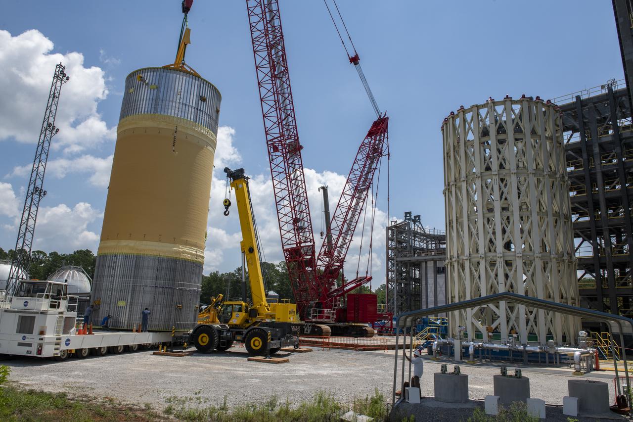
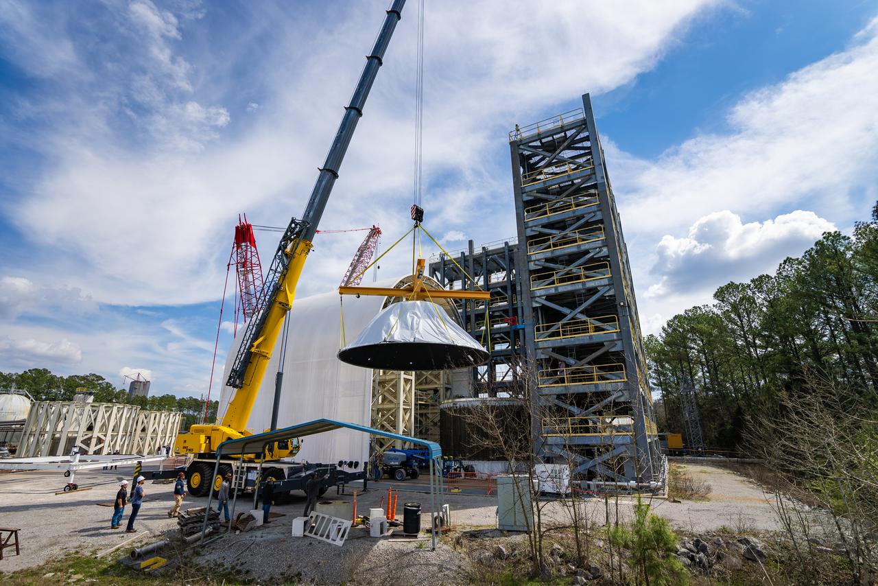
These photos and videos show how crews at NASA’s Marshall Space Flight Center in Huntsville, Alabama, moved and installed the payload adapter that will be used in the Block 1B configuration of the SLS (Space Launch System) rocket from Building 4708, where it was manufactured, into Structural Test Stand 4697 at NASA’s Marshall Space Flight Center on March 13. Teams at Marshall will begin structural testing the engineering development unit of the payload adapter – an exact replica of the flight version of the hardware – this spring. The cone-shaped payload adapter is about 8.5 feet tall and features two metal rings and eight composite panels. The adapter, which will debut on NASA’s Artemis IV mission, is an evolution from the Orion stage adapter used in the Block 1 configuration of the first three Artemis missions. It will be housed inside the universal stage adapter atop the rocket’s more powerful in-space stage, called the exploration upper stage. The payload adapter, like the launch vehicle stage adapter and the Orion stage adapter, is fully manufactured and tested at Marshall, which manages the SLS Program. NASA is working to land the first woman, first person of color, and its first international partner astronaut on the Moon under Artemis. SLS is part of NASA’s backbone for deep space exploration, along with the Orion spacecraft and Gateway in orbit around the Moon and commercial human landing systems, next-generational spacesuits, and rovers on the lunar surface. SLS is the only rocket that can send Orion, astronauts, and supplies to the Moon in a single launch.
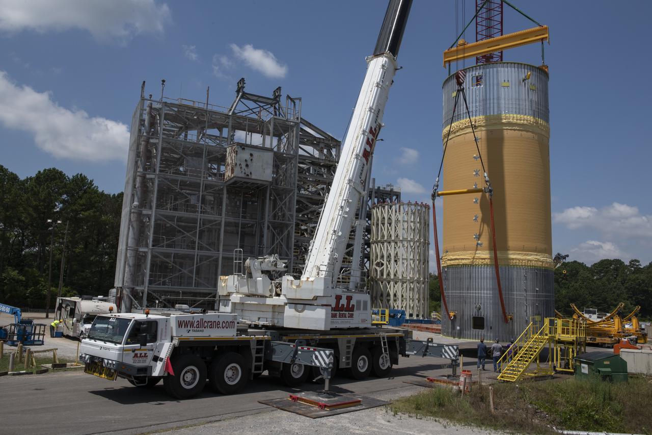
These photos and videos show how crews at NASA’s Marshall Space Flight Center in Huntsville, Alabama, moved and installed the payload adapter that will be used in the Block 1B configuration of the SLS (Space Launch System) rocket from Building 4708, where it was manufactured, into Structural Test Stand 4697 at NASA’s Marshall Space Flight Center on March 13. Teams at Marshall will begin structural testing the engineering development unit of the payload adapter – an exact replica of the flight version of the hardware – this spring. The cone-shaped payload adapter is about 8.5 feet tall and features two metal rings and eight composite panels. The adapter, which will debut on NASA’s Artemis IV mission, is an evolution from the Orion stage adapter used in the Block 1 configuration of the first three Artemis missions. It will be housed inside the universal stage adapter atop the rocket’s more powerful in-space stage, called the exploration upper stage. The payload adapter, like the launch vehicle stage adapter and the Orion stage adapter, is fully manufactured and tested at Marshall, which manages the SLS Program. NASA is working to land the first woman, first person of color, and its first international partner astronaut on the Moon under Artemis. SLS is part of NASA’s backbone for deep space exploration, along with the Orion spacecraft and Gateway in orbit around the Moon and commercial human landing systems, next-generational spacesuits, and rovers on the lunar surface. SLS is the only rocket that can send Orion, astronauts, and supplies to the Moon in a single launch.