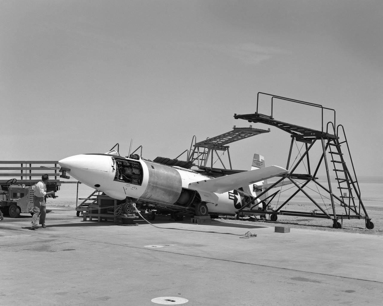
Bell X-1A ejection seat test setup
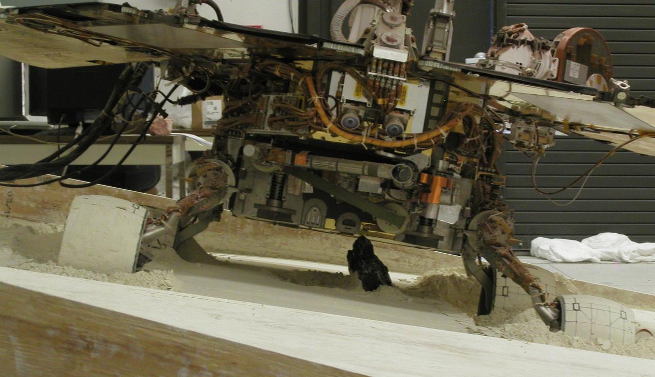
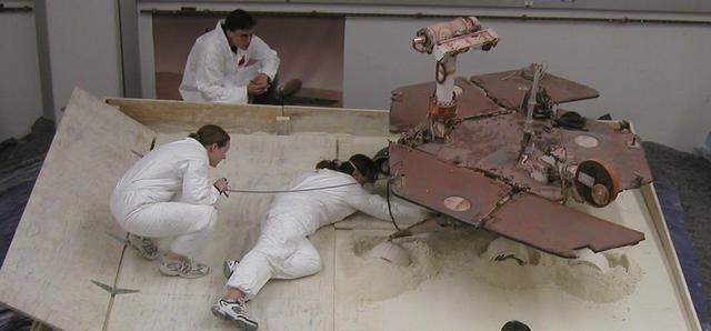
With a slope of about 10 degrees and a pointy rock under the test rover belly, this sandbox setup at NASA JPL, is ready for engineers to use the test rover to assess possible moves for getting Mars rover Spirit out of a patch of loose Martian soil.
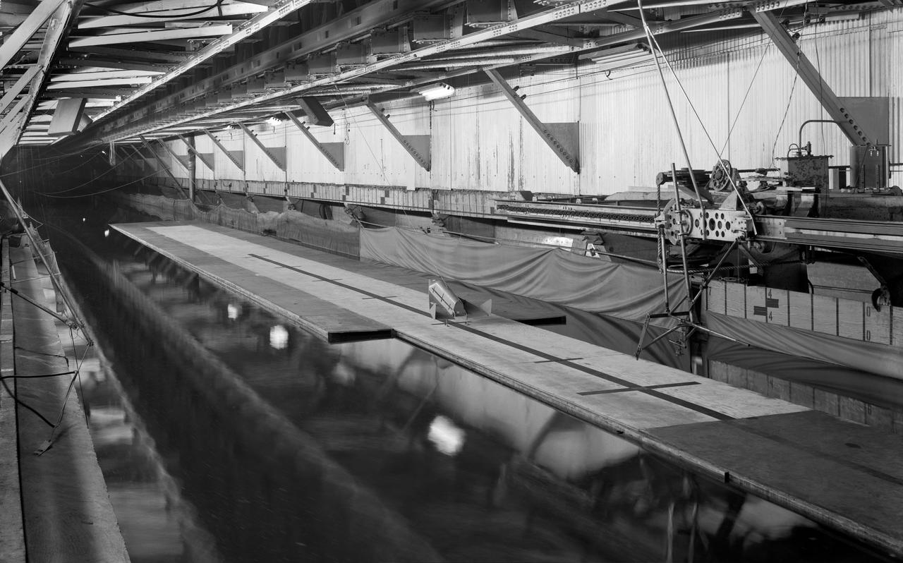
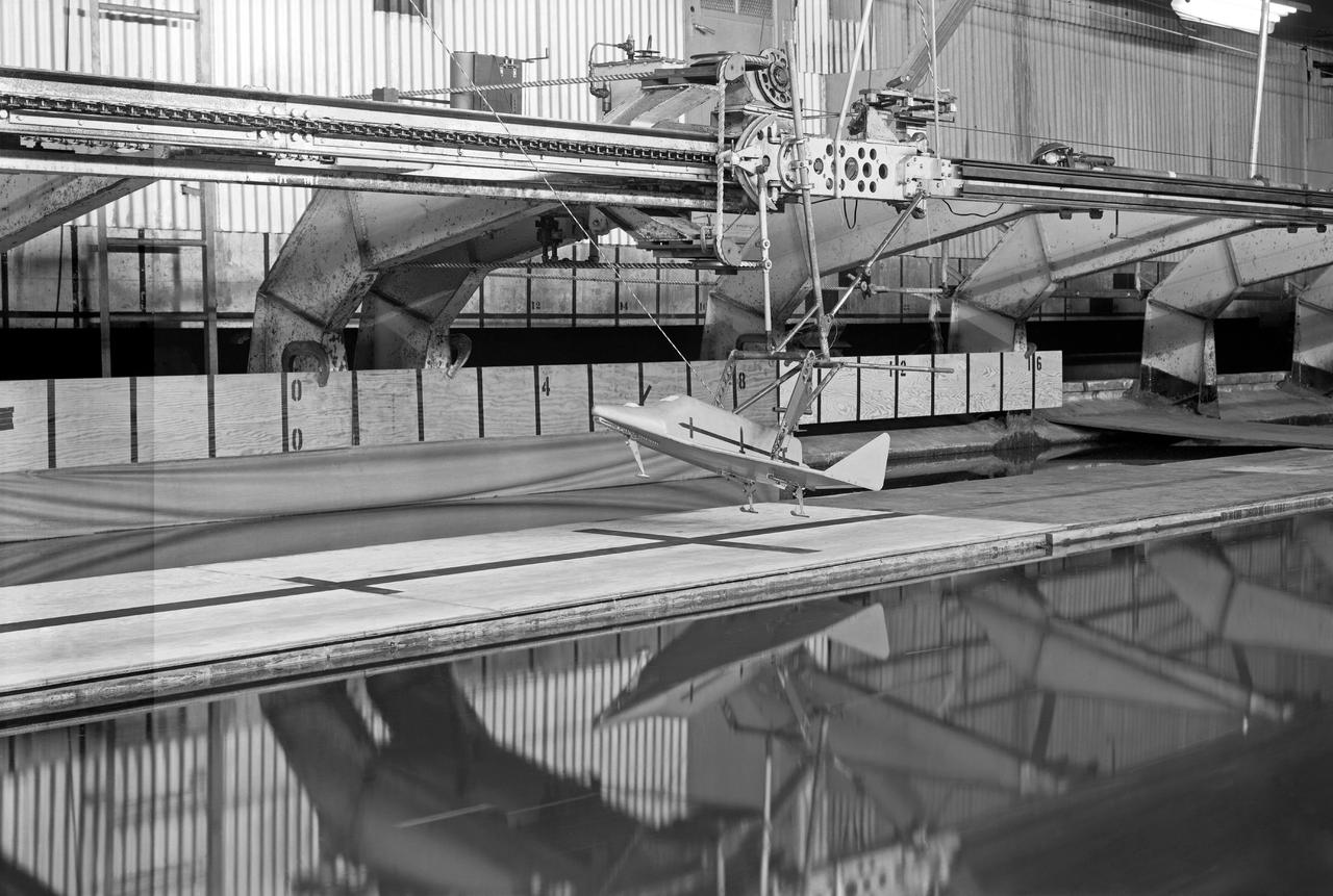
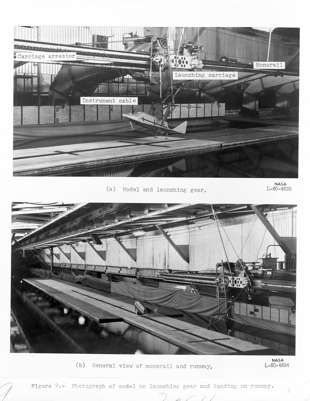
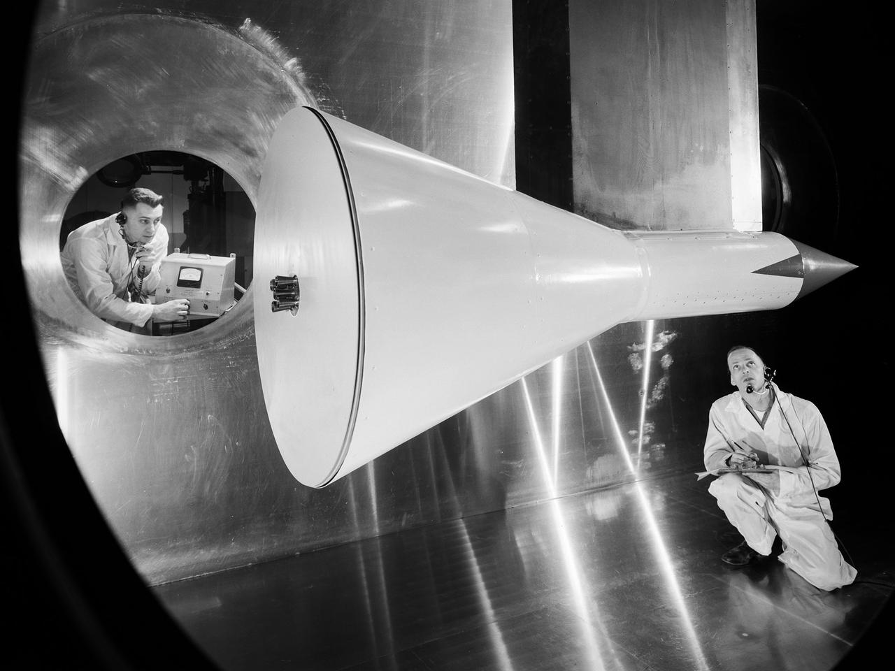
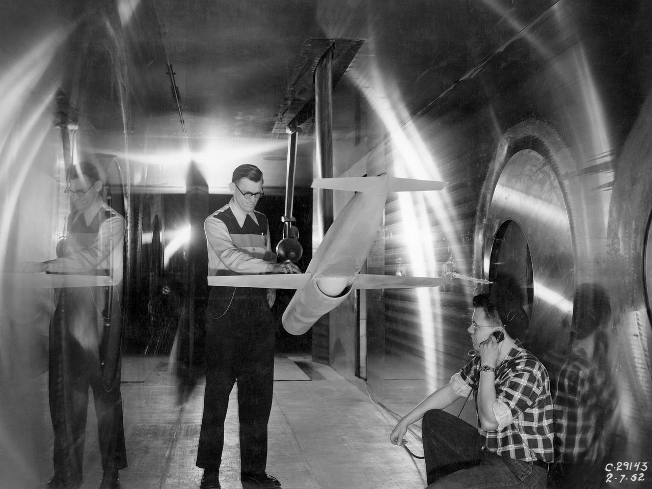
Test Setup For Model Landing Investigation of a Winged Space Vehicle Image used in NASA Document TN-D-1496 1960-L-04633.01 is Figure 9a for NASA Document L-2064 Photograph of model on launcher and landing on runway.
Test Setup For Model Landing Investigation of a Winged Space Vehicle Image used in NASA Document TN-D-1496 1960-L-04633.01 is Figure 9a for NASA Document L-2064 Photograph of model on launcher and landing on runway.
Test Setup For Model Landing Investigation of a Winged Space Vehicle Image used in NASA Document TN-D-1496 1960-L-04633.01 is Figure 9a for NASA Document L-2064 Photograph of model on launcher and landing on runway.
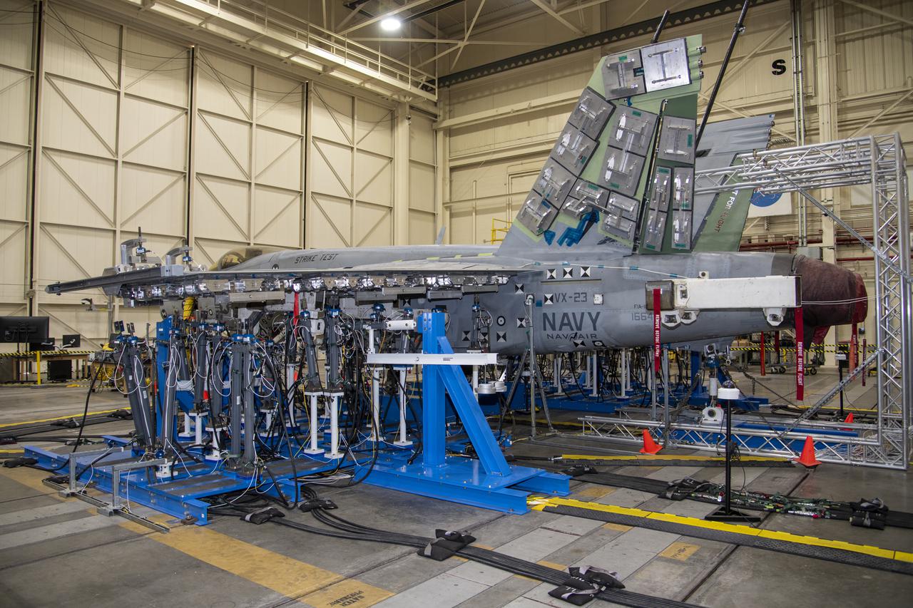
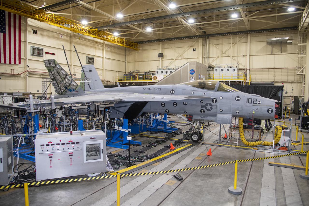
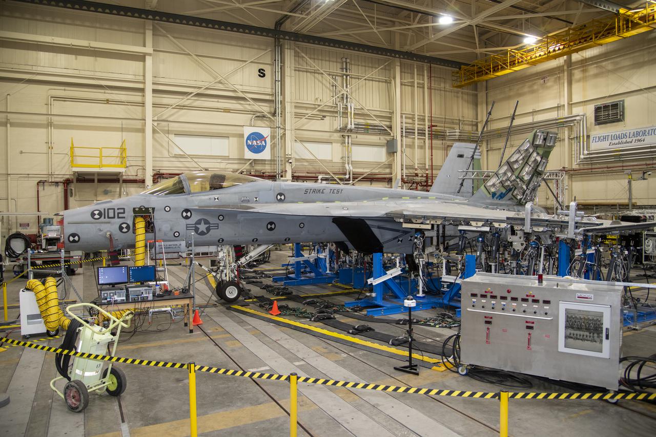
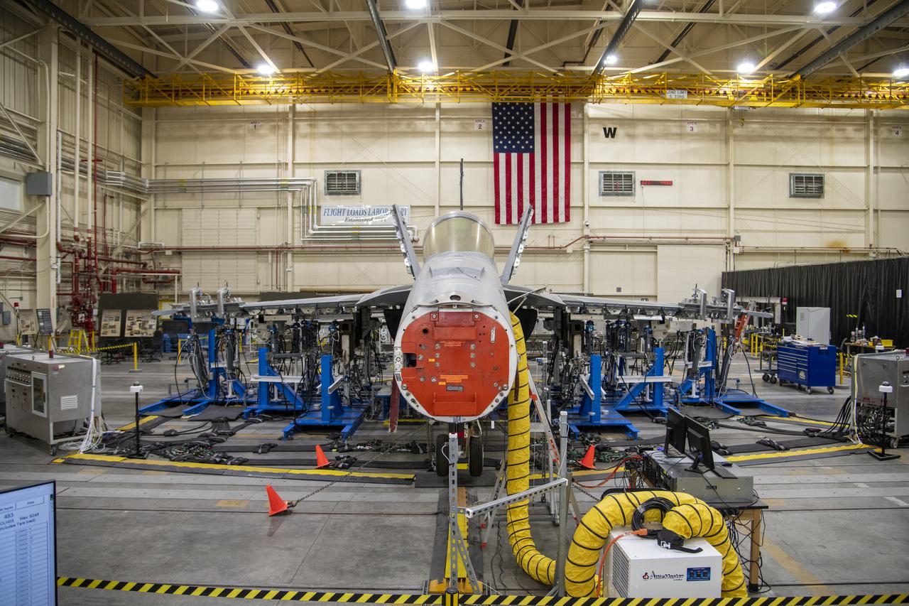
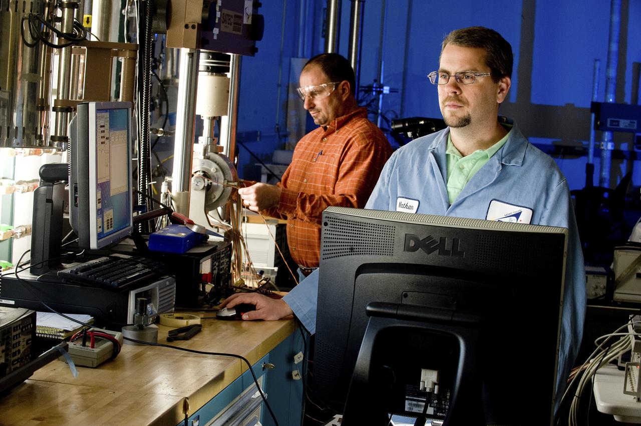
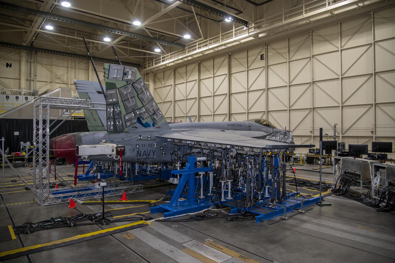
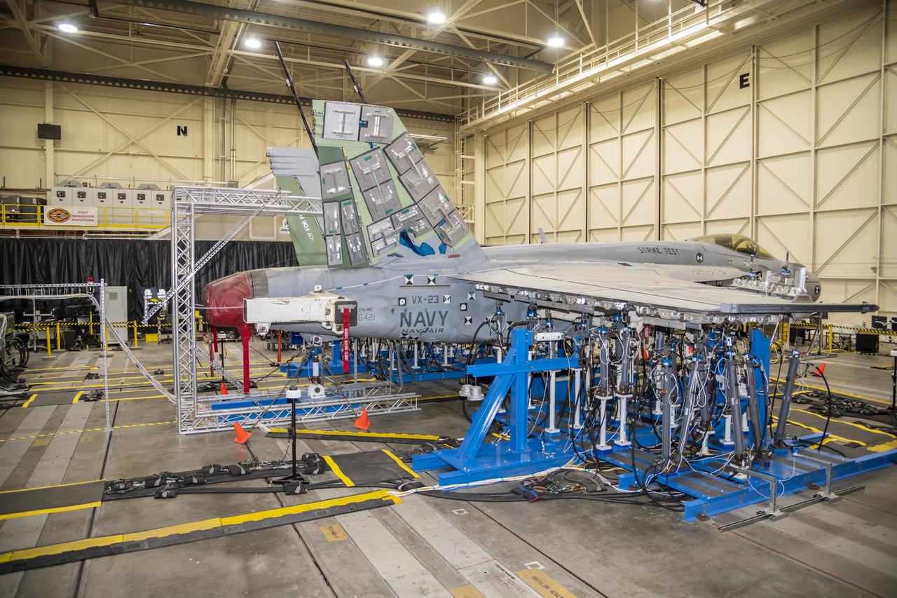
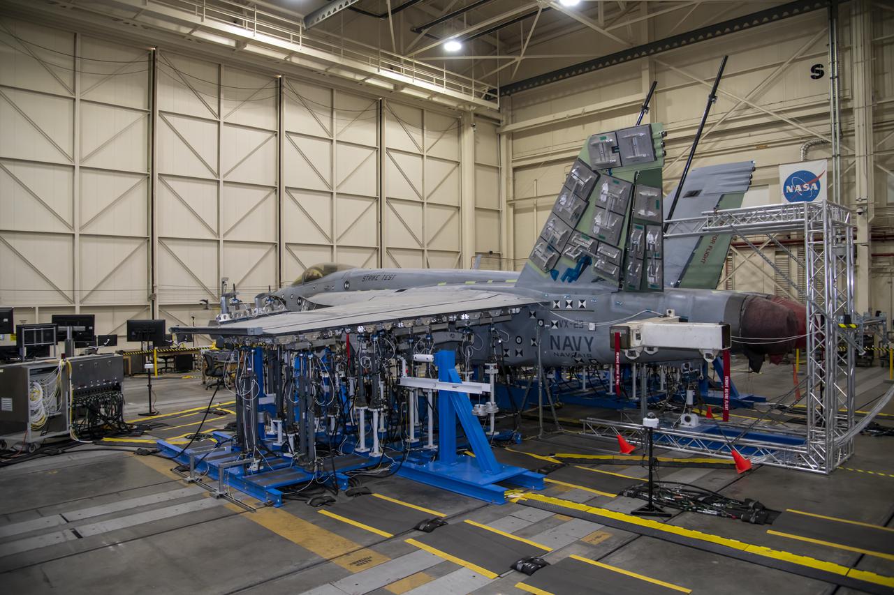
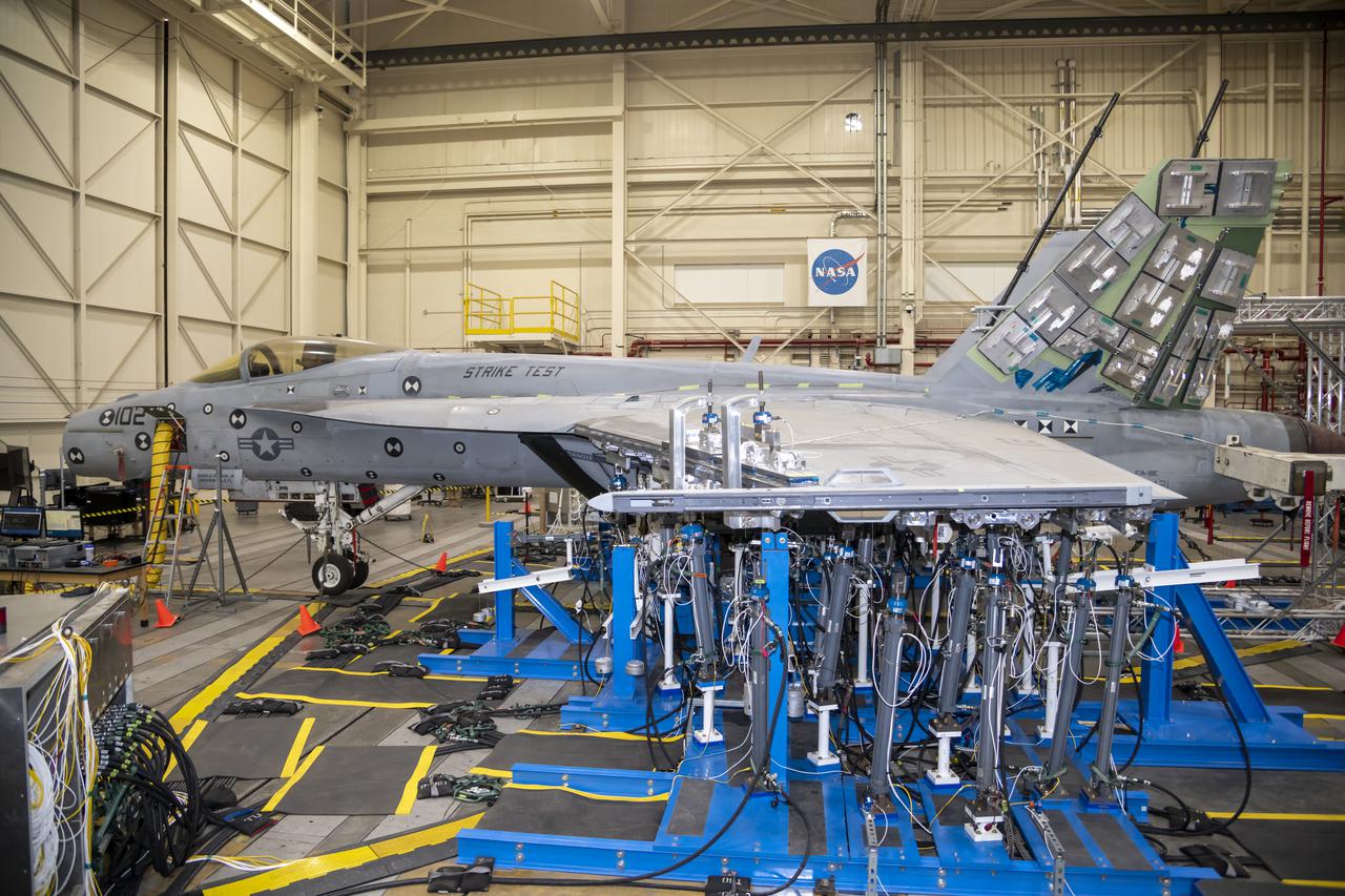
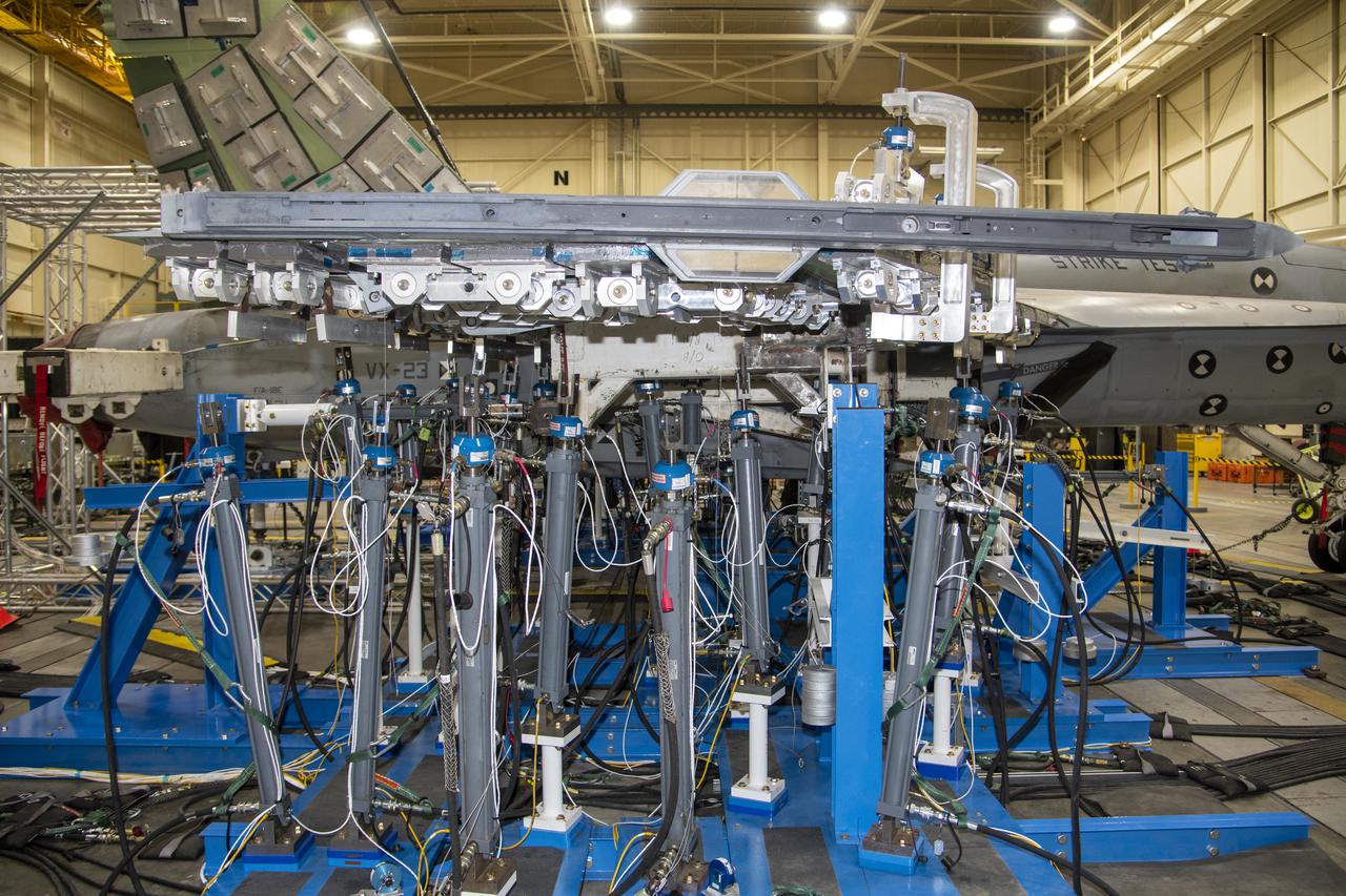
NASA’s Armstrong Flight Research Center Flight Loads Laboratory in Edwards, California, is working on one of its biggest load calibrations tests on an F/A-18E Super Hornet from the Naval Air Systems Command (NAVAIR) in Patuxent River, Maryland. This testing is needed before the aircraft can serve as a test vehicle for determining if it can safely manage maneuvers and proposed upgrades. This is a view of the test setup for the wing loads testing that is set to begin in December 2021.
NASA’s Armstrong Flight Research Center Flight Loads Laboratory in Edwards, California, is working on one of its biggest load calibrations tests on an F/A-18E Super Hornet from the Naval Air Systems Command (NAVAIR) in Patuxent River, Maryland. This testing is needed before the aircraft can serve as a test vehicle for determining if it can safely manage maneuvers and proposed upgrades. This is a view of the test setup for the wing loads testing that is set to begin in December 2021.
NASA’s Armstrong Flight Research Center Flight Loads Laboratory in Edwards, California, is working on one of its biggest load calibrations tests on an F/A-18E Super Hornet from the Naval Air Systems Command (NAVAIR) in Patuxent River, Maryland. This testing is needed before the aircraft can serve as a test vehicle for determining if it can safely manage maneuvers and proposed upgrades. This is a view of the test setup for the wing loads testing that is set to begin in December 2021.
NASA’s Armstrong Flight Research Center Flight Loads Laboratory in Edwards, California, is working on one of its biggest load calibrations tests on an F/A-18E Super Hornet from the Naval Air Systems Command (NAVAIR) in Patuxent River, Maryland. This testing is needed before the aircraft can serve as a test vehicle for determining if it can safely manage maneuvers and proposed upgrades. This is a view of the test setup for the wing loads testing that is set to begin in December 2021.
NASA’s Armstrong Flight Research Center Flight Loads Laboratory in Edwards, California, is working on one of its biggest load calibrations tests on an F/A-18E Super Hornet from the Naval Air Systems Command (NAVAIR) in Patuxent River, Maryland. This testing is needed before the aircraft can serve as a test vehicle for determining if it can safely manage maneuvers and proposed upgrades. This is a view of the test setup for the wing loads testing that is set to begin in December 2021.
NASA’s Armstrong Flight Research Center Flight Loads Laboratory in Edwards, California, is working on one of its biggest load calibrations tests on an F/A-18E Super Hornet from the Naval Air Systems Command (NAVAIR) in Patuxent River, Maryland. This testing is needed before the aircraft can serve as a test vehicle for determining if it can safely manage maneuvers and proposed upgrades. This is a view of the test setup for the wing loads testing that is set to begin in December 2021.
NASA’s Armstrong Flight Research Center Flight Loads Laboratory in Edwards, California, is working on one of its biggest load calibrations tests on an F/A-18E Super Hornet from the Naval Air Systems Command (NAVAIR) in Patuxent River, Maryland. This testing is needed before the aircraft can serve as a test vehicle for determining if it can safely manage maneuvers and proposed upgrades. This is a view of the test setup for the wing loads testing that is set to begin in December 2021.

NASA’s Armstrong Flight Research Center Flight Loads Laboratory in Edwards, California, is working on one of its biggest load calibrations tests on an F/A-18E Super Hornet from the Naval Air Systems Command (NAVAIR) in Patuxent River, Maryland. This testing is needed before the aircraft can serve as a test vehicle for determining if it can safely manage maneuvers and proposed upgrades. This is a view of the test setup for the wing loads testing that is set to begin in December 2021.
NASA’s Armstrong Flight Research Center Flight Loads Laboratory in Edwards, California, is working on one of its biggest load calibrations tests on an F/A-18E Super Hornet from the Naval Air Systems Command (NAVAIR) in Patuxent River, Maryland. This testing is needed before the aircraft can serve as a test vehicle for determining if it can safely manage maneuvers and proposed upgrades. This is a view of the test setup for the wing loads testing that is set to begin in December 2021.
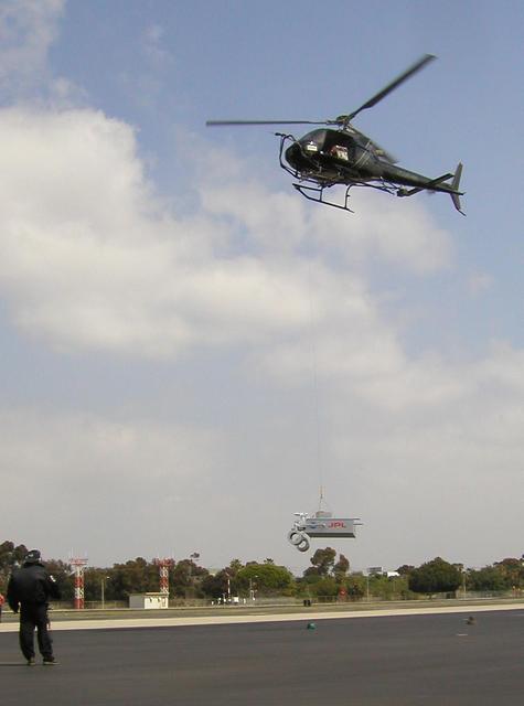
This image taken March 25, 2010 shows preparations for radar testing for NASA Mars Science Laboratory. This day work evaluated a setup for suspending a rover mock-up beneath a helicopter at Hawthorne Municipal Airport, Hawthorne, Calif.
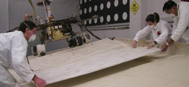
NASA Mars Exploration Rover team members prepare a testing setup for a subsequent experiment after an experiment driving the rover in a crablike motion, with all four corner wheels angled to the right.
A test setup at NASA Jet Propulsion Laboratory enables experiments with maneuvers being considered for use by NASA Mars Exploration Rover Spirit to get Spirit out of soft soil where it has become embedded.

TEST SETUP FOR SHUTTER VALVE FLOW TEST
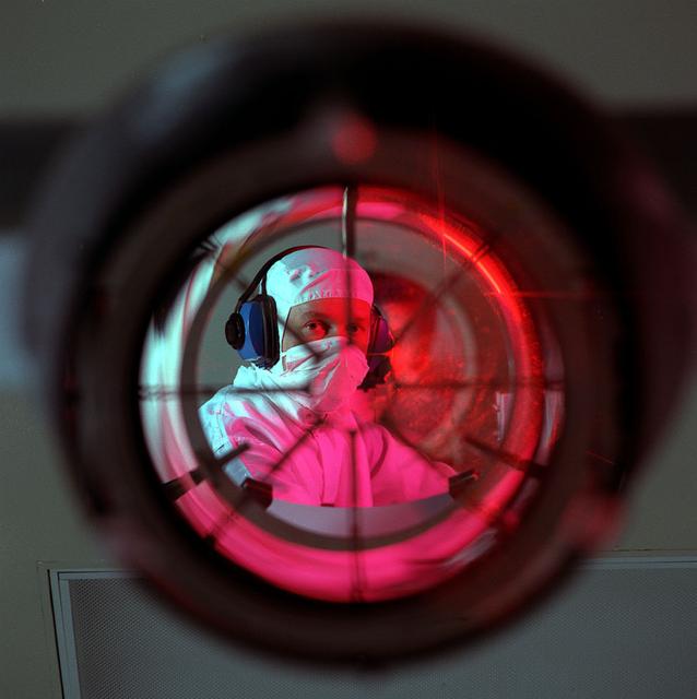
Advanced X-Ray Astrophysics Facility-S (AXAF-S) nickel prototype mirror optical test setup.
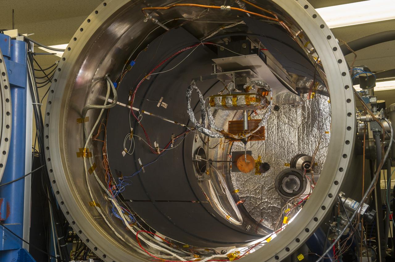
BLDG. 4605 PLASMA ENVIRONMENT TEST LABORATORY. VACUUM CHAMBER OPEN WITH SAMPLE SETUP
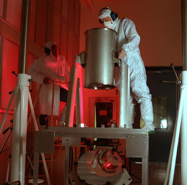
Advanced X-Ray Astrophysics Facility-S (AXAF-S) nickel prototype mirror optical test setup.
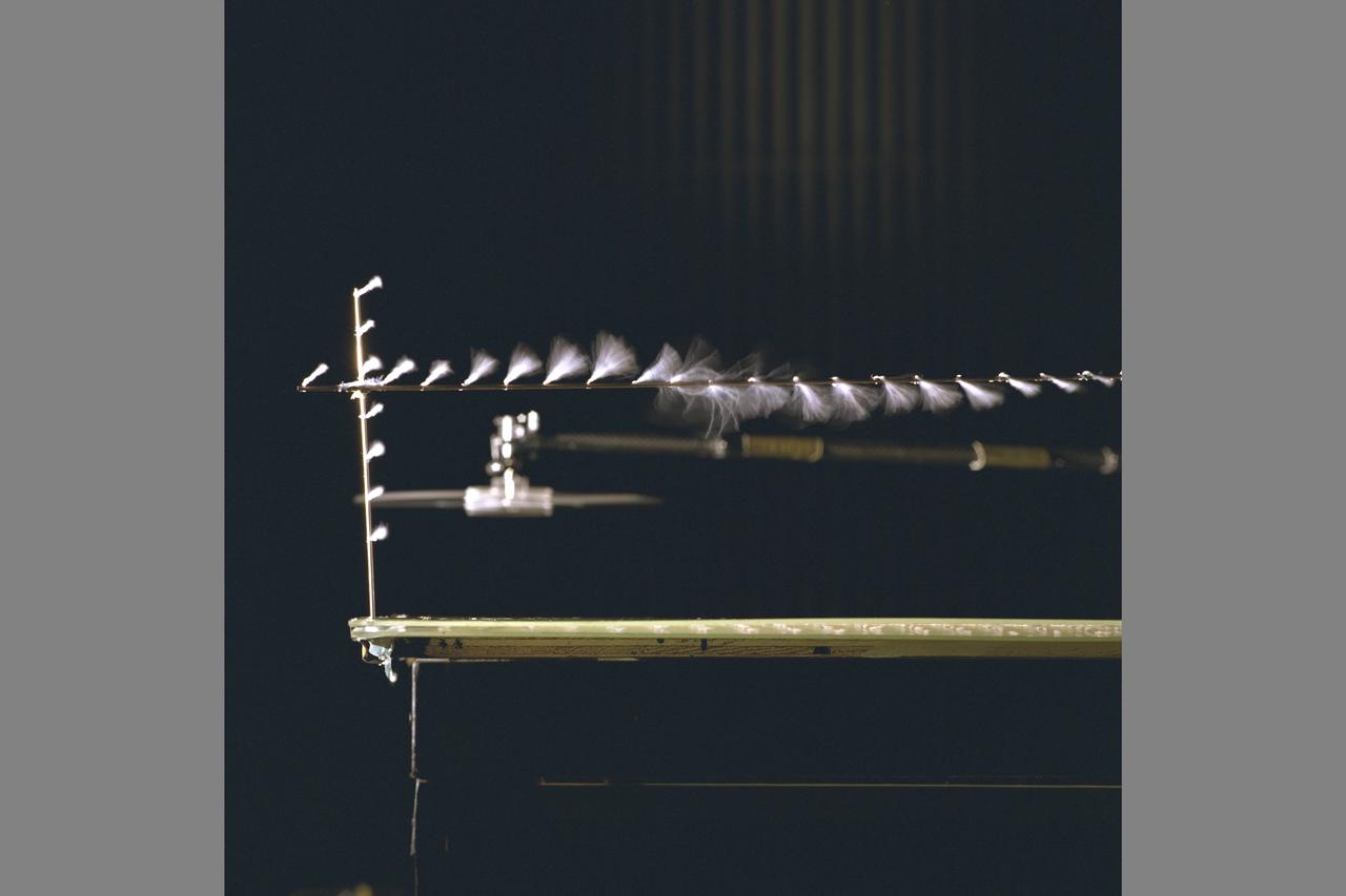
Ship Airwake investigation 7x10FT#2 W.t. settling Chamber. Shows test setup and model flow visuaization using microtufts and UV ilumination
Ship Airwake investigation 7x10FT#2 W.t. settling Chamber. Shows test setup and model flow visuaization using microtufts and UV ilumination
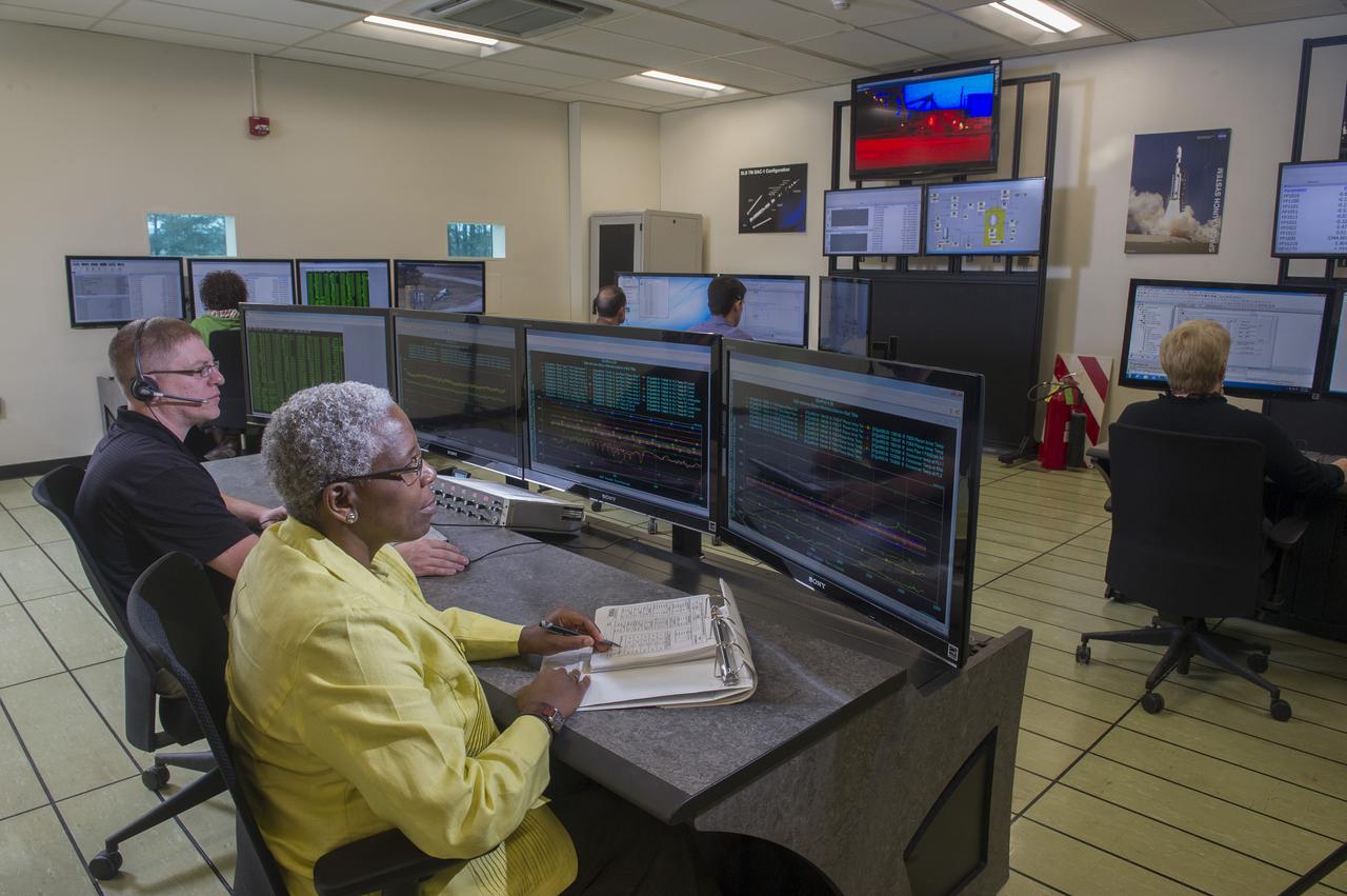
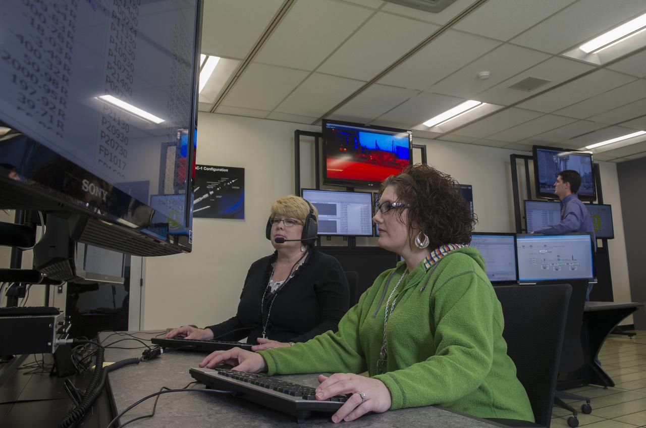
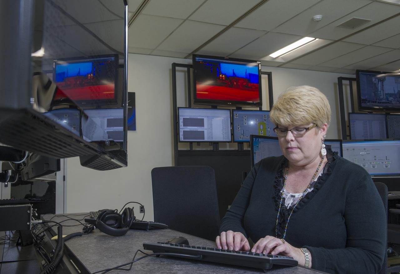
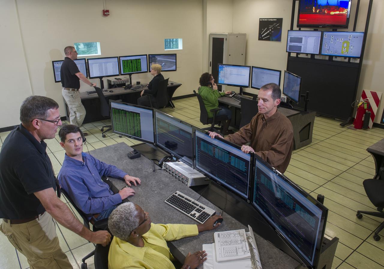
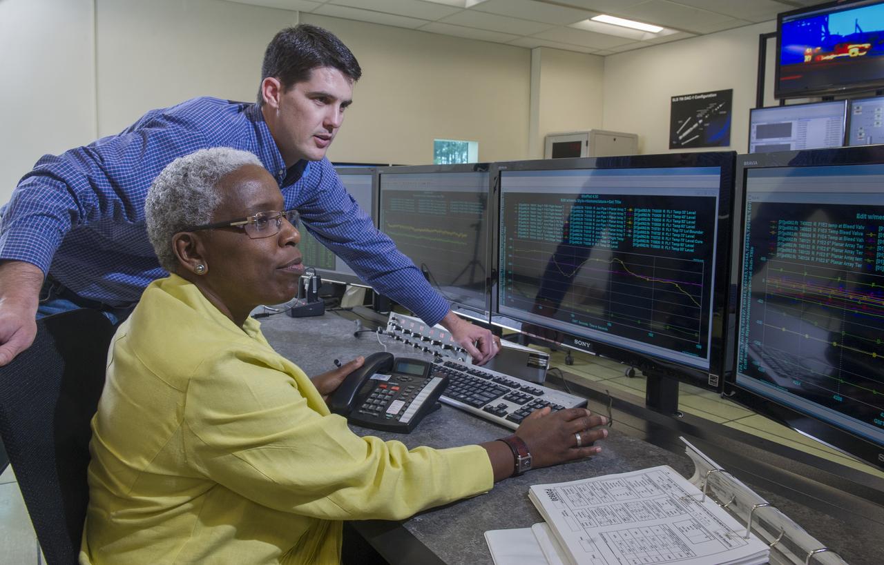
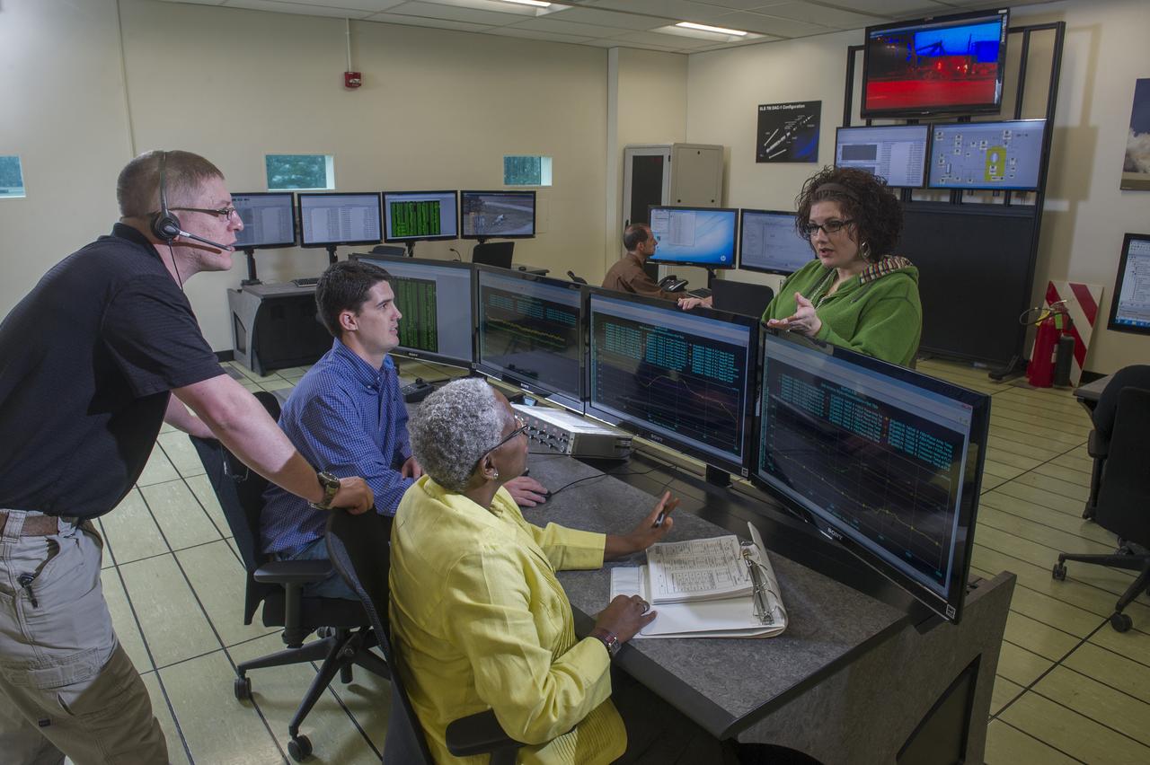
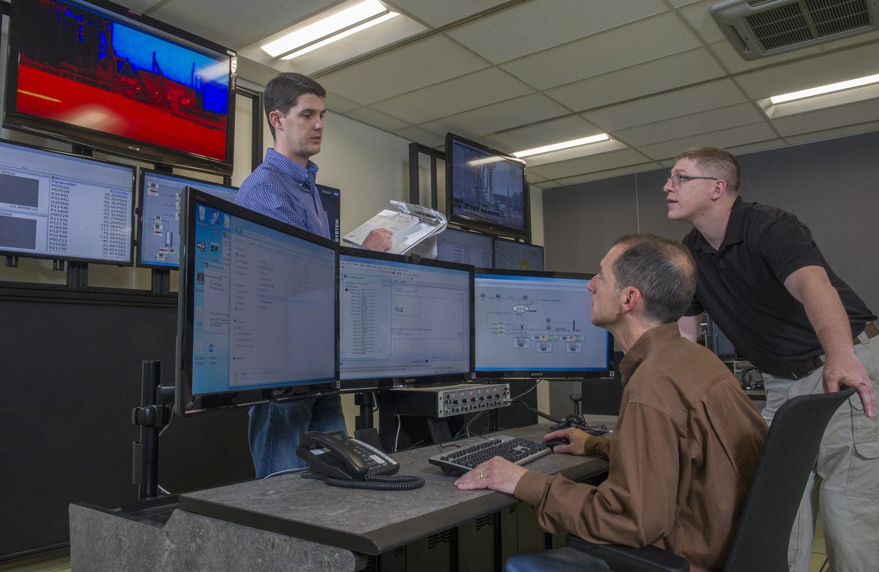
STEVEN SPRAYBERRY, ALICE DANIEL, CHRISTY BASHMAN, ALLEN SHELTON, BEVERELY COURREGE, MATHEW EXELL, JIM EMMENEGGER, IN VARIOUS SETUPS AT WEST TEST AREA CONTROL ROOM-B.
STEVEN SPRAYBERRY, ALICE DANIEL, CHRISTY BASHMAN, ALLEN SHELTON, BEVERELY COURREGE, MATHEW EXELL, JIM EMMENEGGER, IN VARIOUS SETUPS AT WEST TEST AREA CONTROL ROOM-B.
STEVEN SPRAYBERRY, ALICE DANIEL, CHRISTY BASHMAN, ALLEN SHELTON, BEVERELY COURREGE, MATHEW EXELL, JIM EMMENEGGER, IN VARIOUS SETUPS AT WEST TEST AREA CONTROL ROOM-B.
STEVEN SPRAYBERRY, ALICE DANIEL, CHRISTY BASHMAN, ALLEN SHELTON, BEVERELY COURREGE, MATHEW EXELL, JIM EMMENEGGER, IN VARIOUS SETUPS AT WEST TEST AREA CONTROL ROOM-B.
STEVEN SPRAYBERRY, ALICE DANIEL, CHRISTY BASHMAN, ALLEN SHELTON, BEVERELY COURREGE, MATHEW EXELL, JIM EMMENEGGER, IN VARIOUS SETUPS AT WEST TEST AREA CONTROL ROOM-B.
STEVEN SPRAYBERRY, ALICE DANIEL, CHRISTY BASHMAN, ALLEN SHELTON, BEVERELY COURREGE, MATHEW EXELL, JIM EMMENEGGER, IN VARIOUS SETUPS AT WEST TEST AREA CONTROL ROOM-B.
STEVEN SPRAYBERRY, ALICE DANIEL, CHRISTY BASHMAN, ALLEN SHELTON, BEVERELY COURREGE, MATHEW EXELL, JIM EMMENEGGER, IN VARIOUS SETUPS AT WEST TEST AREA CONTROL ROOM-B.
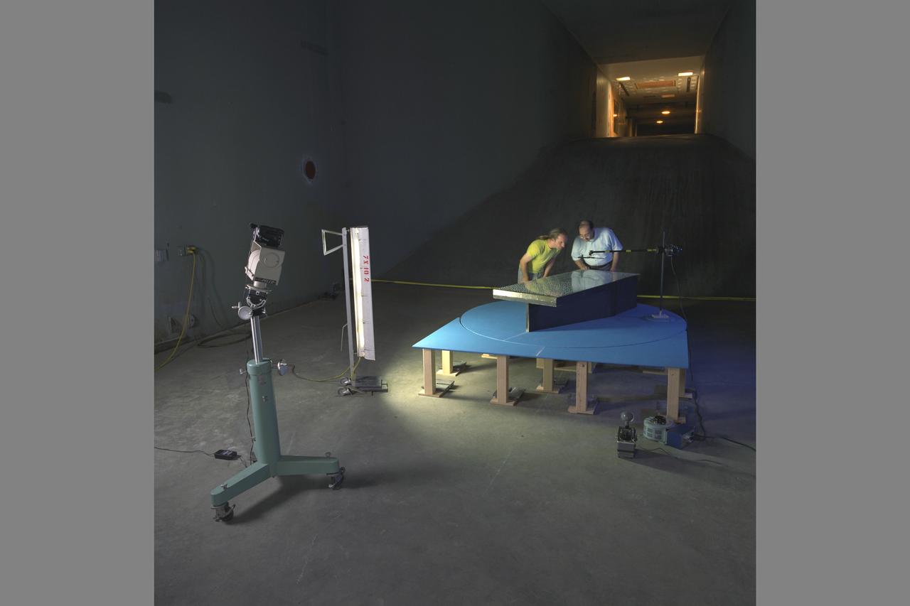
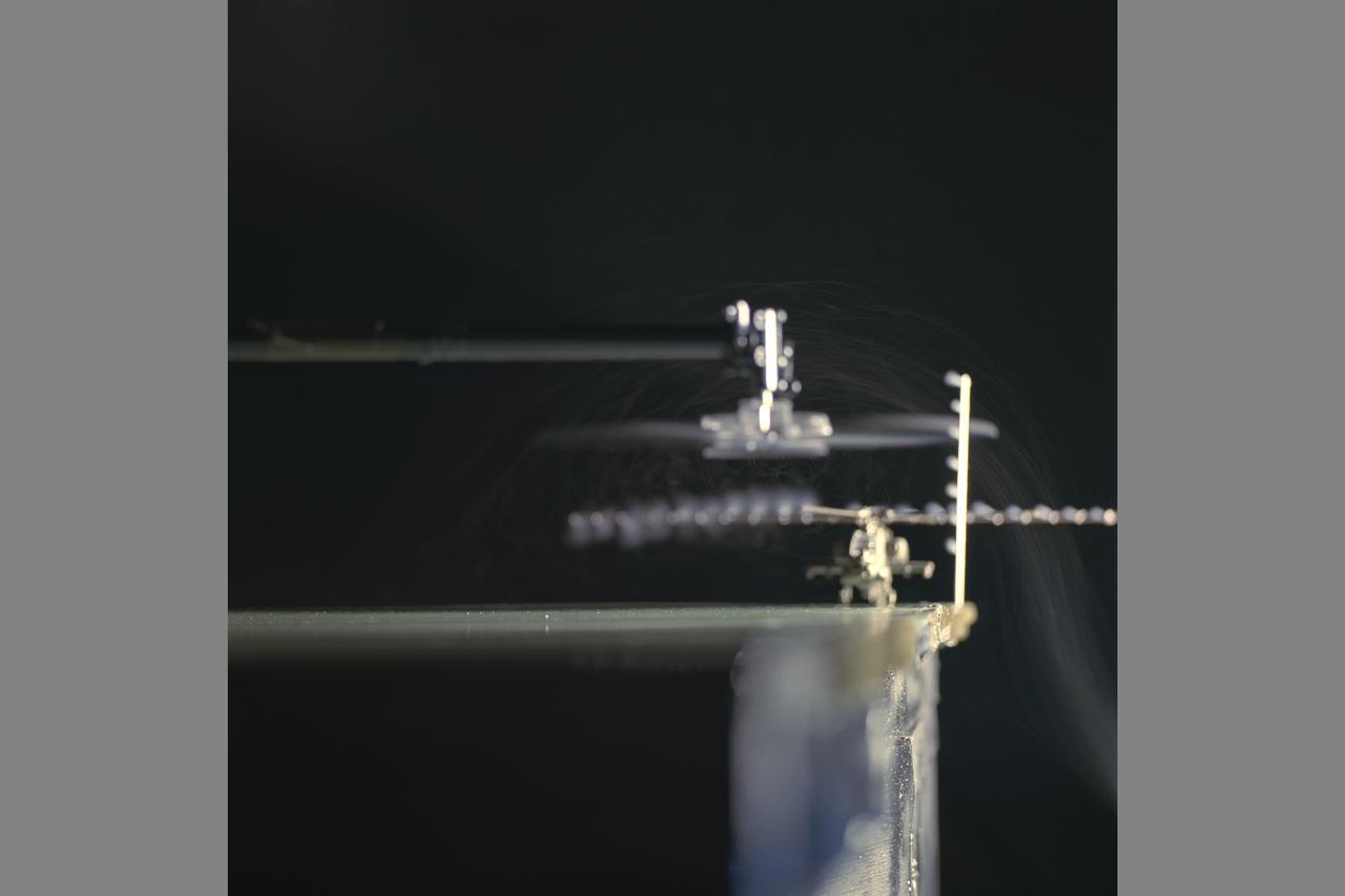
Test Setup and UltraViolet (UV) Lighting with Frank Caradonna, Ames and Kurtis Long, Project Scientist. Ship Airwake Investigation 7 x 10 ft#2 Wind Tunnel Settling Chamber.
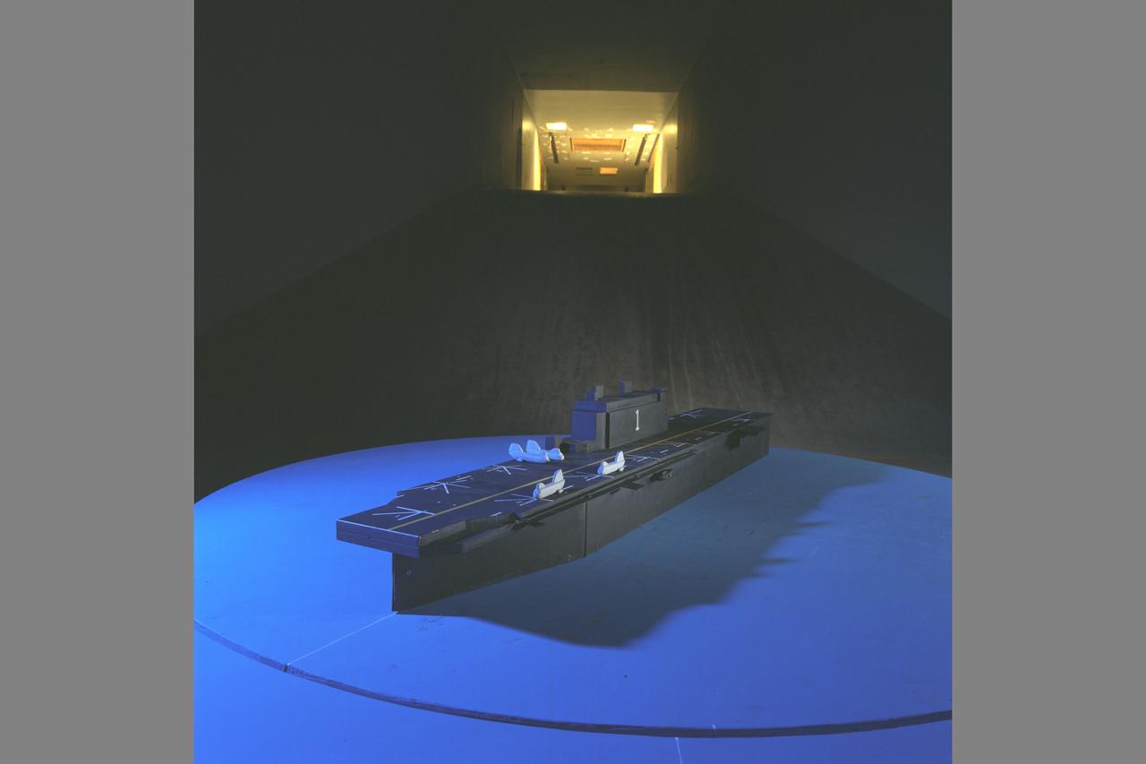
Test Setup and UltraViolet (UV) Lighting and Tufts. Ship Airwake Investigation 7 x 10 ft#2 Wind Tunnel Settling Chamber. Bridge and rotorcraft added to flight deck
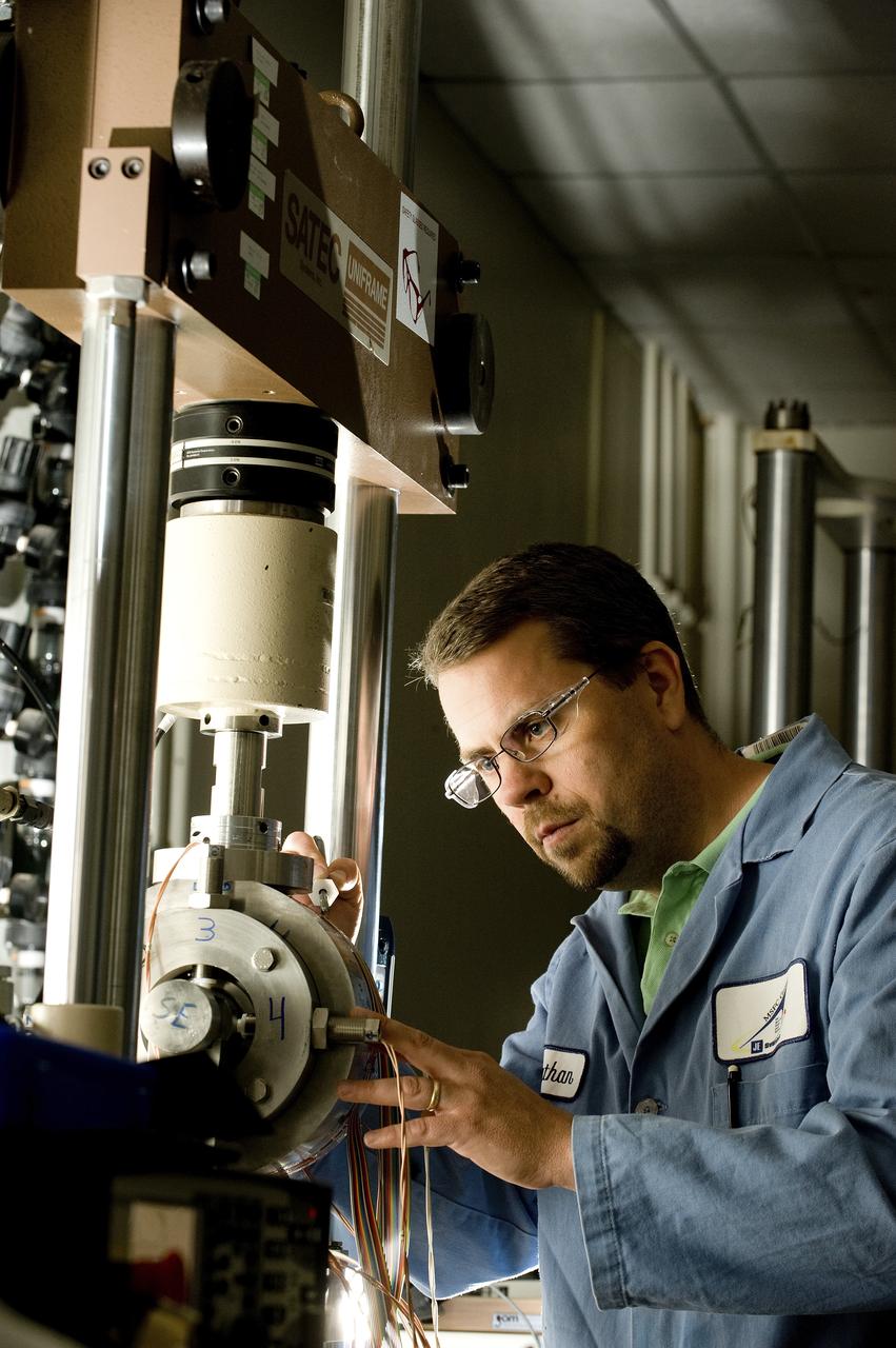
TATHAN COFFEE (EM10 MATERIALS TEST ENGINEER, JACOBS ESTS GROUP/JTI) ADJUSTS A UNIQUE MECHANICAL TEST SETUP THAT MEASURES STRAIN ON A SINGLE SAMPLE, USING TWO DIFFERENT TECHNIQUES AT THE SAME TIME. THE TEST FIXTURE HOLDS A SPECIMEN THAT REPRESENTS A LIQUID OXYGEN (LOX) BEARING FROM THE J2-X ENGINE
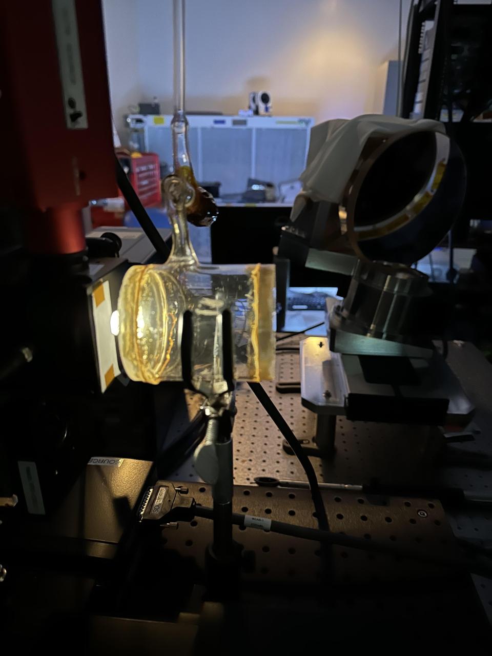
Methane, a potent greenhouse gas, is contained in a glowing cylinder during a September 2023 test conducted by engineers at NASA's Jet Propulsion Laboratory in Southern California of a state-of-the-art imaging spectrometer. The instrument will measure methane and carbon dioxide from space. Designed and built by JPL, imaging spectrometer will be part of an effort led by the nonprofit Carbon Mapper organization to collect data on greenhouse gas point-source emissions. The information will help locate and quantify "super-emitters" – the small percentage of individual sources responsible for a significant fraction of methane and carbon dioxide emissions around the world. https://photojournal.jpl.nasa.gov/catalog/PIA26097
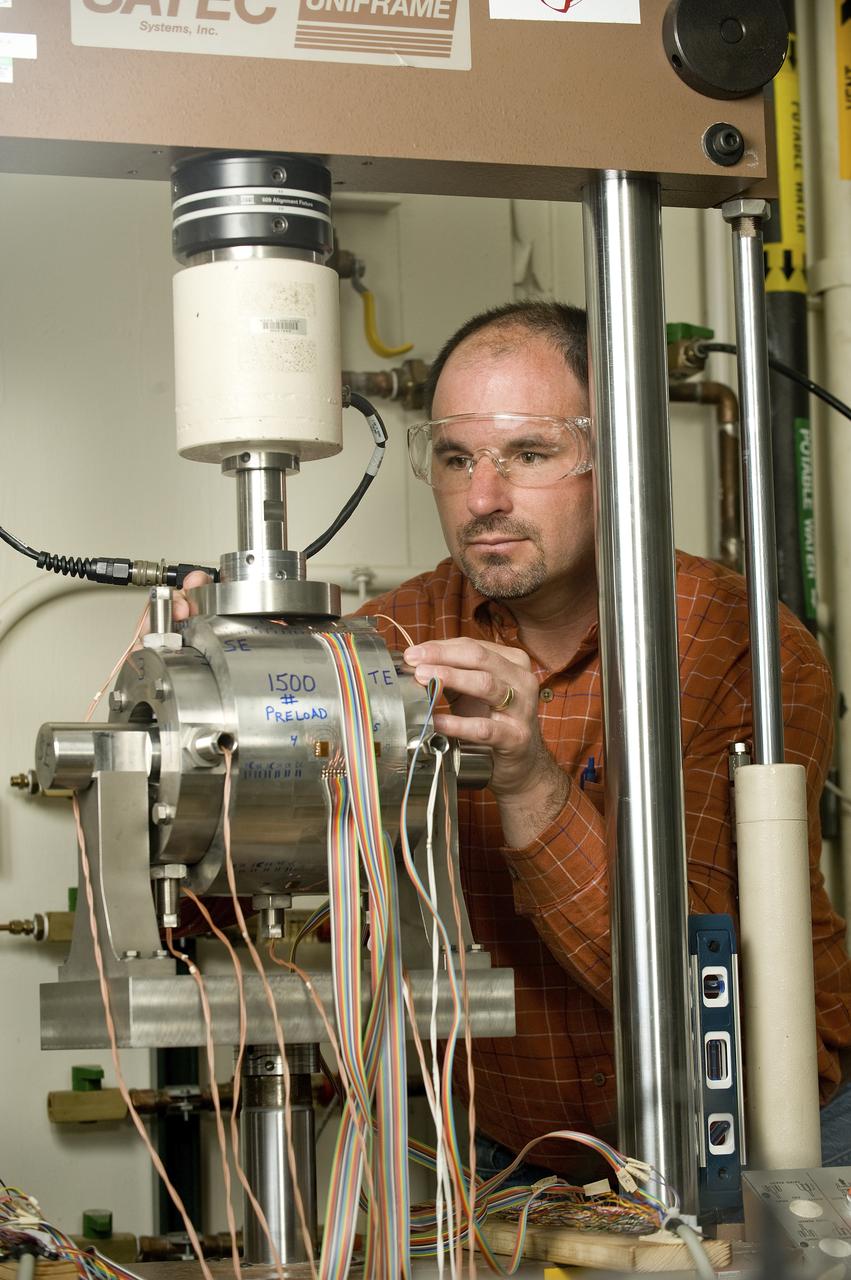
HORACE STORNG (AEROSPACE ENGINEER, ER31 PROPULSION TURBOMACHINERY DESIGN & DEVELOPMENT BRANCH) ADJUSTS A UNIQUE MECHANICAL TEST SETUP THAT MEASURES STRAIN ON A SINGLE SAMPLE, USING TWO DIFFERENT TECHNIQUES AT THE SAME TIME. THE TEST FIXTURE HOLDS A SPECIMEN THAT REPRESENTS A LIQUID OXYGEN (LOX) BEARING FROM THE J2-X ENGINE
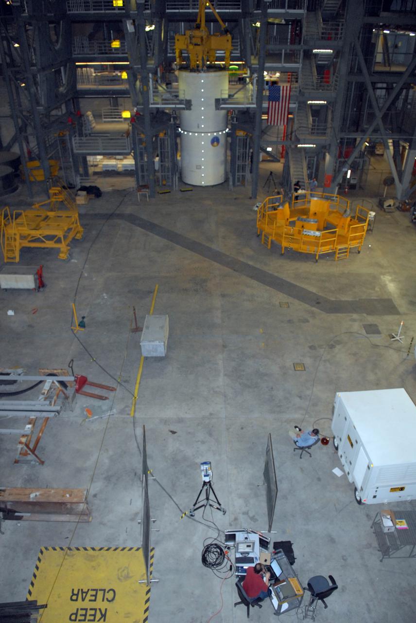
CAPE CANAVERAL, Fla. -- Vibration and laser testing is being conducted on Ares I-X segments at NASA's Kennedy Space Center. This is an overall view of the modal testing setup using the Inert Solid Rocket Motor Segment and Laser Vibrometer in high bay 4 of the Vehicle Assembly building. Photo credit: NASA/Dimitri Gerondidakis
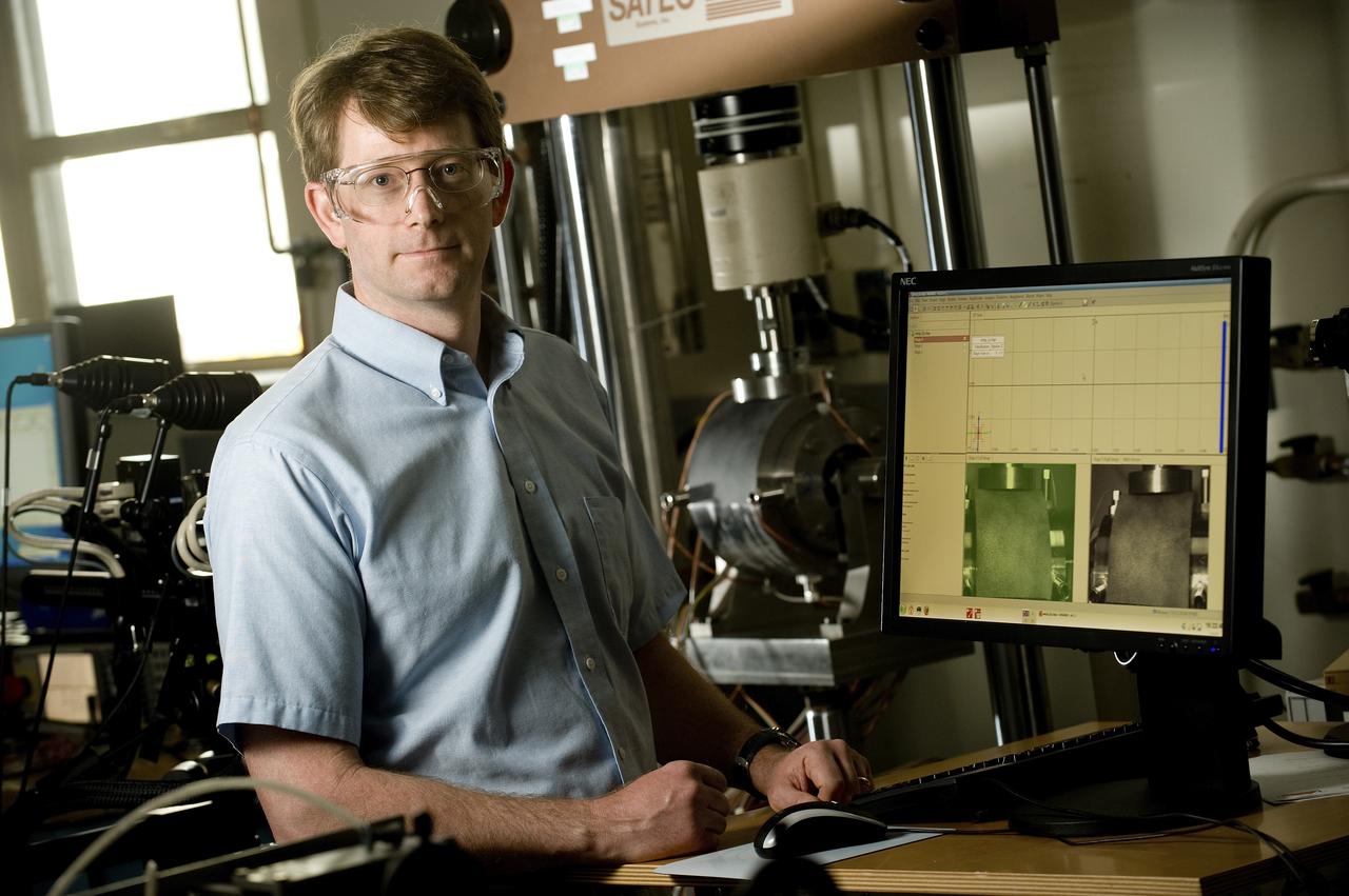
ERIC EARHART (AEROSPACE ENGINEER, ER41 PROPULSION STRUCTURAL & DYNAMICS ANALYSIS BRANCH) DISCUSSES DATA PRODUCED BY A UNIQUE MECHANICAL TEST SETUP THAT MEASURES STRAIN ON A SINGLE SAMPLE, USING TWO DIFFERENT TECHNIQUES AT THE SAME TIME. THE TEST FIXTURE HOLDS A SPECIMEN THAT REPRESENTS A LIQUID OXYGEN (LOX) BEARING FROM THE J2-X ENGINE
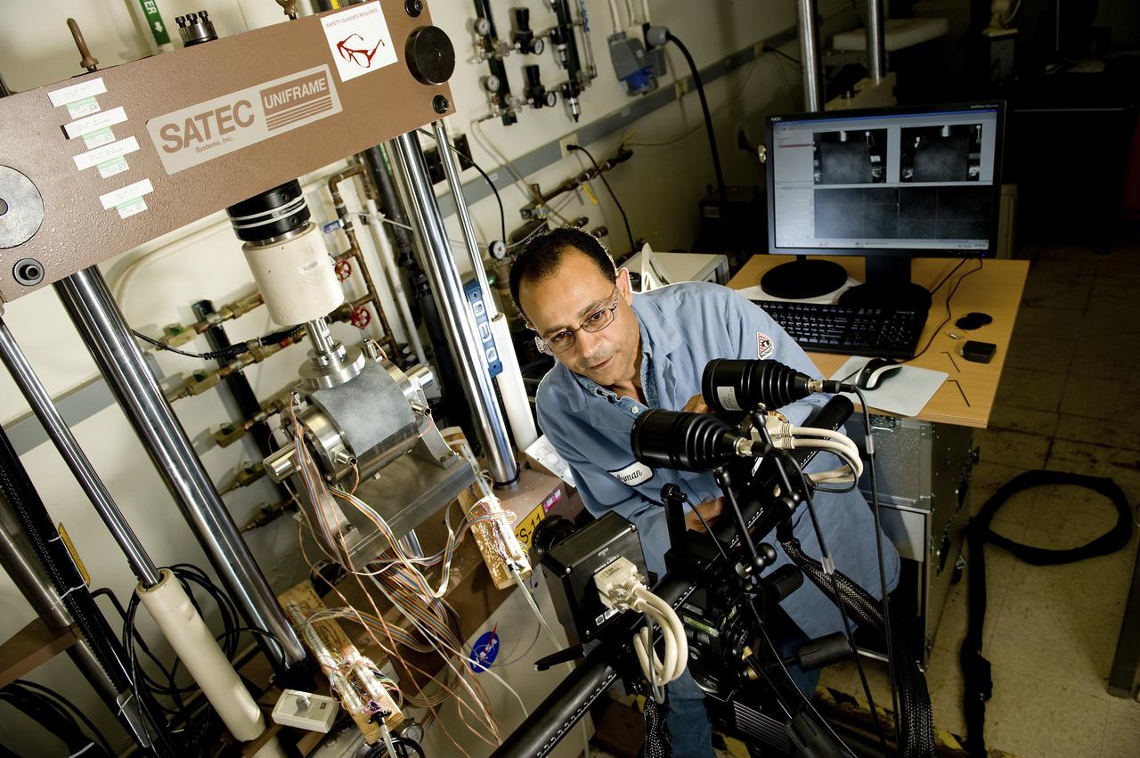
AYMAN GIRGIS (EM10 MATERIALS TEST ENGINEER, JACOBS ESTS GROUP/JTI) ADJUSTS DUAL LENSES FOR A UNIQUE MECHANICAL TST SETUP THAT MEASURES STRAIN ON A SINGLE SAMPLE, USING TWO DIFFERENT TECHNIQUES AT THE SAME TIME. THE TEST FIXTURE HOLDS A SPECIMEN THAT REPRESENTS A LIQUID OXYGEN (LOX) BEARING FROM THE J2-X ENGINE
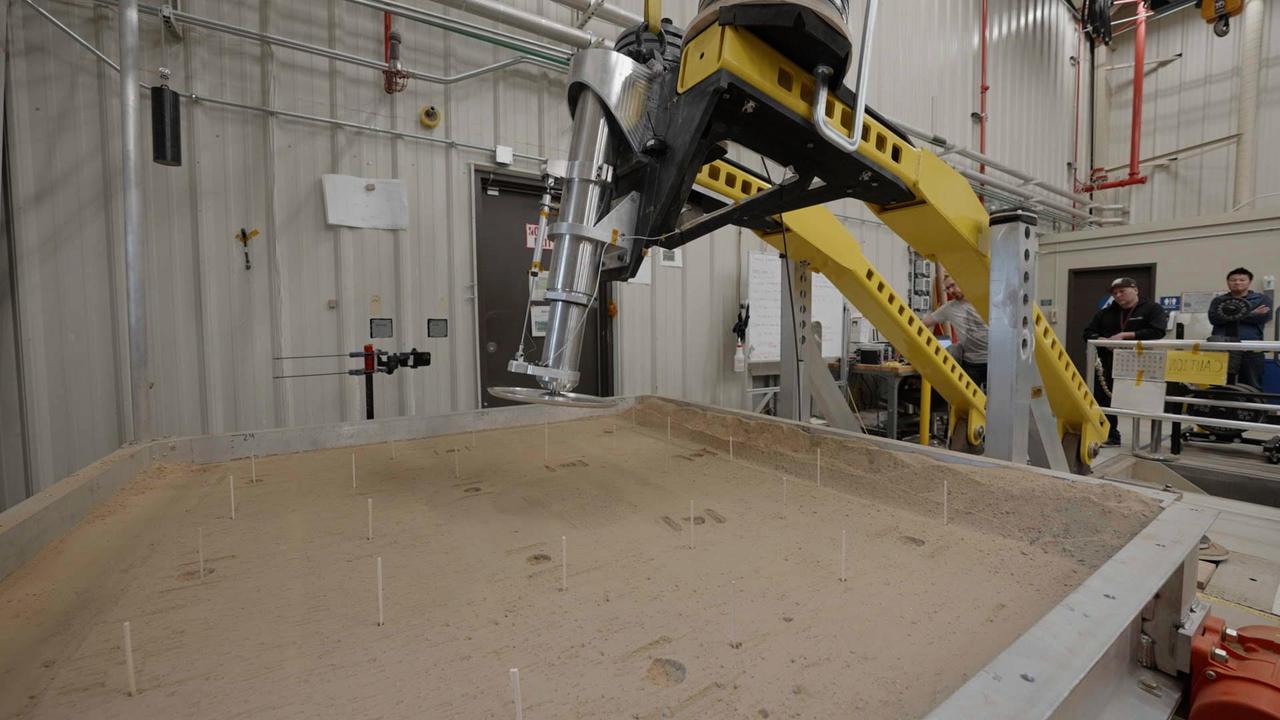
This setup is being used at NASA's Jet Propulsion Laboratory to test a 16-inch-diameter (40-centimeter-diameter) footpad for a future Mars lander. The footpad was plunged into a test bed filled with 10,000 pounds (4,536 kilograms) of simulated Martian soil in order to see how deep it would sink – too far, and the lander's belly could scrape against the ground during touchdown, damaging it. The Sample Retrieval Lander, which would be central to NASA's Mars Sample Return campaign, is estimated to weigh as much as 5,016 pounds (2,275 kilograms). It would be the heaviest spacecraft ever to land on the Red Planet. In order to understand how energy would be absorbed during the landing of such a massive spacecraft, JPL engineers have been conducting drop tests of a full-size footpad. Mars Sample Return will revolutionize our understanding of Mars by bringing scientifically selected samples to Earth for study using the most sophisticated instrumentation around the world. NASA's planned Mars Sample Return (MSR) campaign would fulfill one of the highest priority solar system exploration goals identified by the National Academies of Sciences, Engineering and Medicine in the past three decadal surveys. This strategic partnership with the ESA (European Space Agency) features the first mission to return samples from another planet, including the first launch from the surface of another planet. The samples being collected by NASA's Perseverance rover during its exploration of an ancient river delta are thought to be the best opportunity to reveal the early evolution of Mars, including the potential for ancient life. https://photojournal.jpl.nasa.gov/catalog/PIA25824
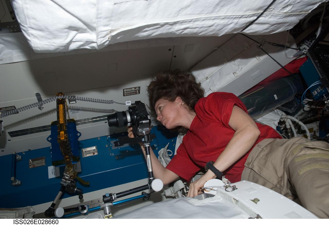
ISS026-E-028660 (23 Feb. 2011) --- NASA astronaut Catherine (Cady) Coleman, Expedition 26 flight engineer, uses a digital still camera to photograph the Binary Colloidal Alloy Test-5 (BCAT-5) payload setup in the Kibo laboratory of the International Space Station.

ISS026-E-028666 (23 Feb. 2011) --- NASA astronaut Scott Kelly, Expedition 26 commander, uses a digital still camera to photograph the Binary Colloidal Alloy Test-5 (BCAT-5) payload setup in the Kibo laboratory of the International Space Station.
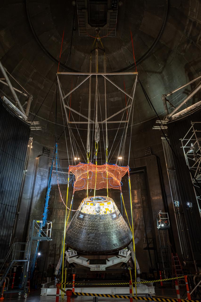
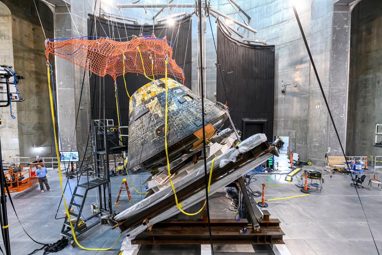
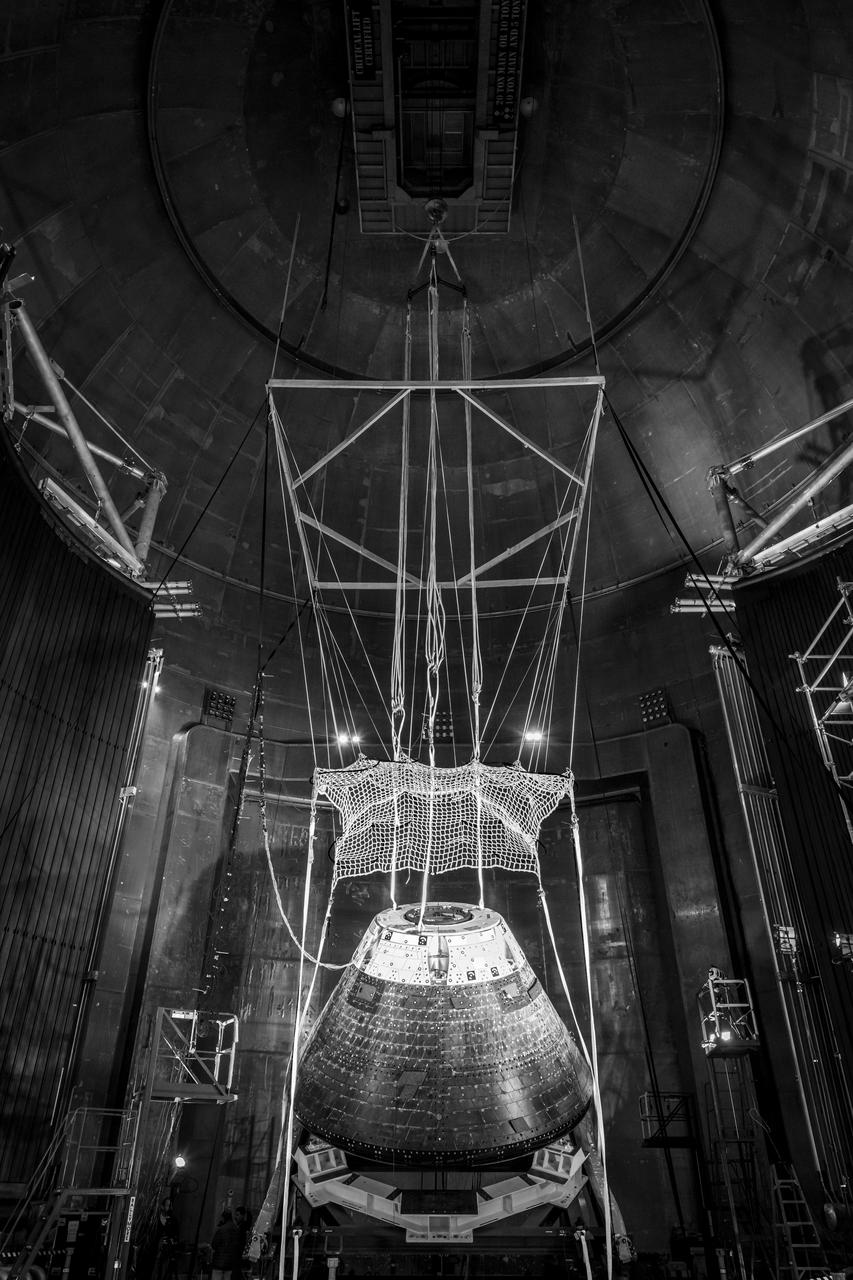
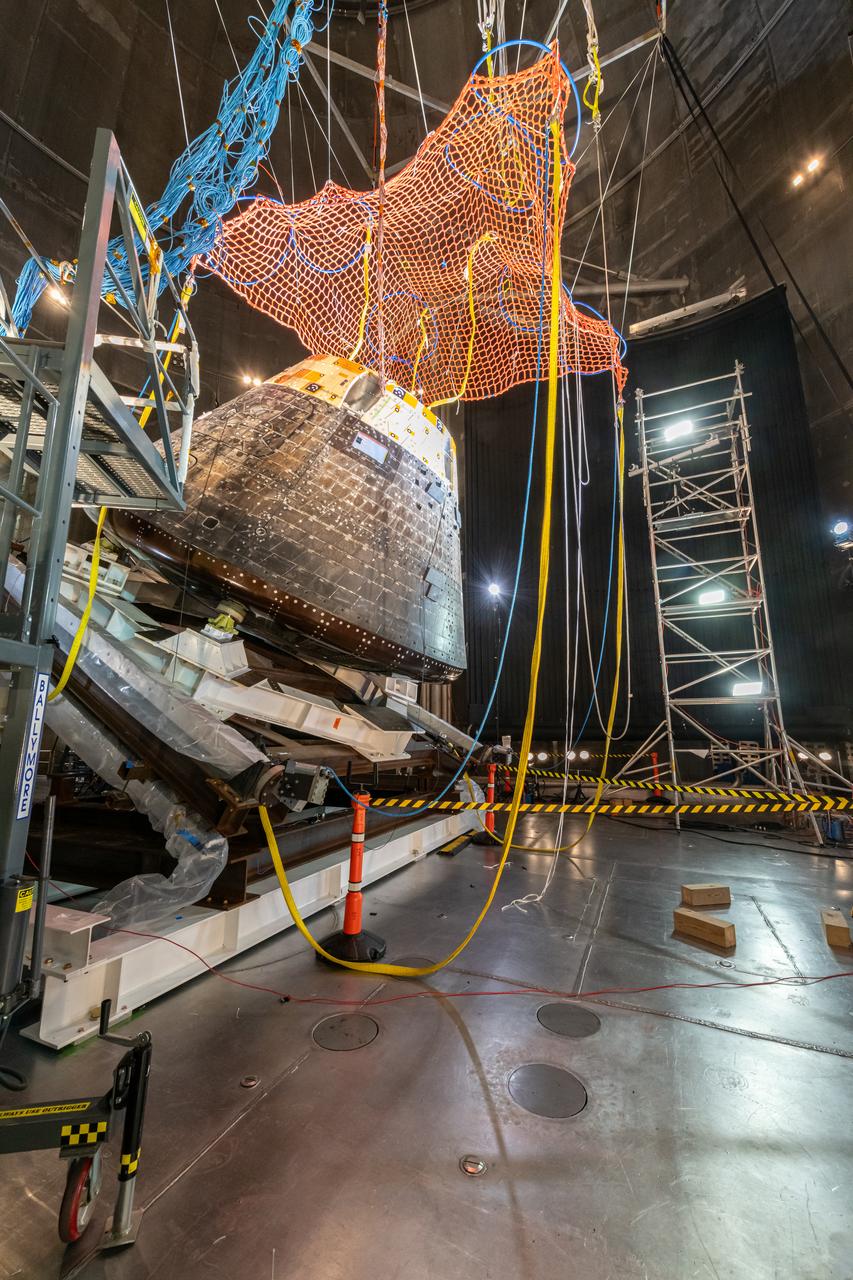
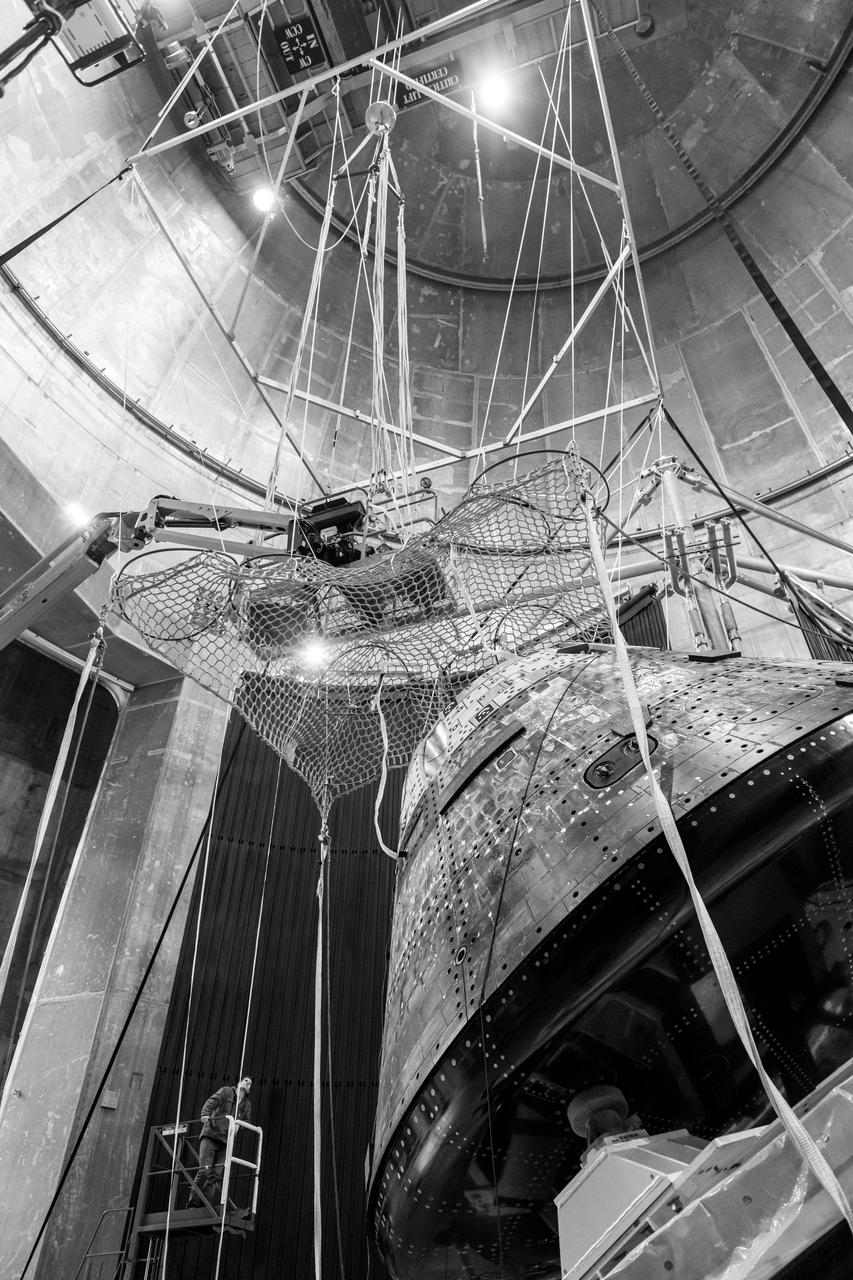
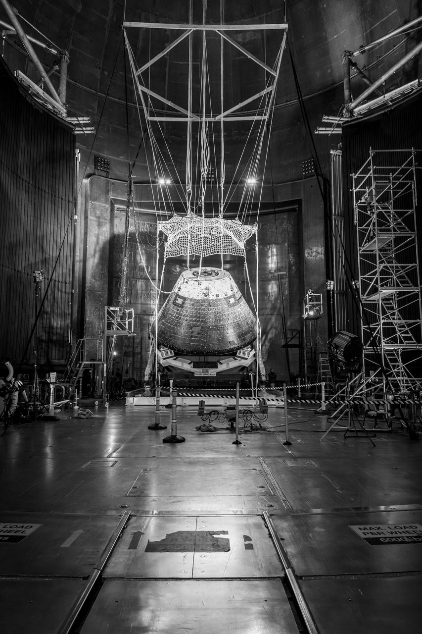
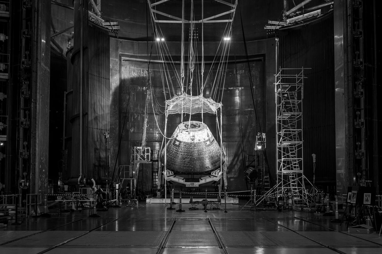
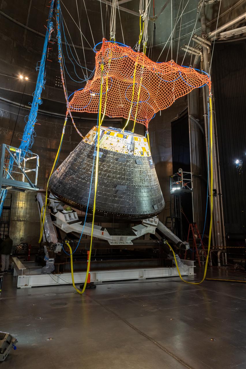
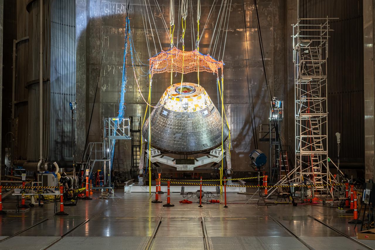
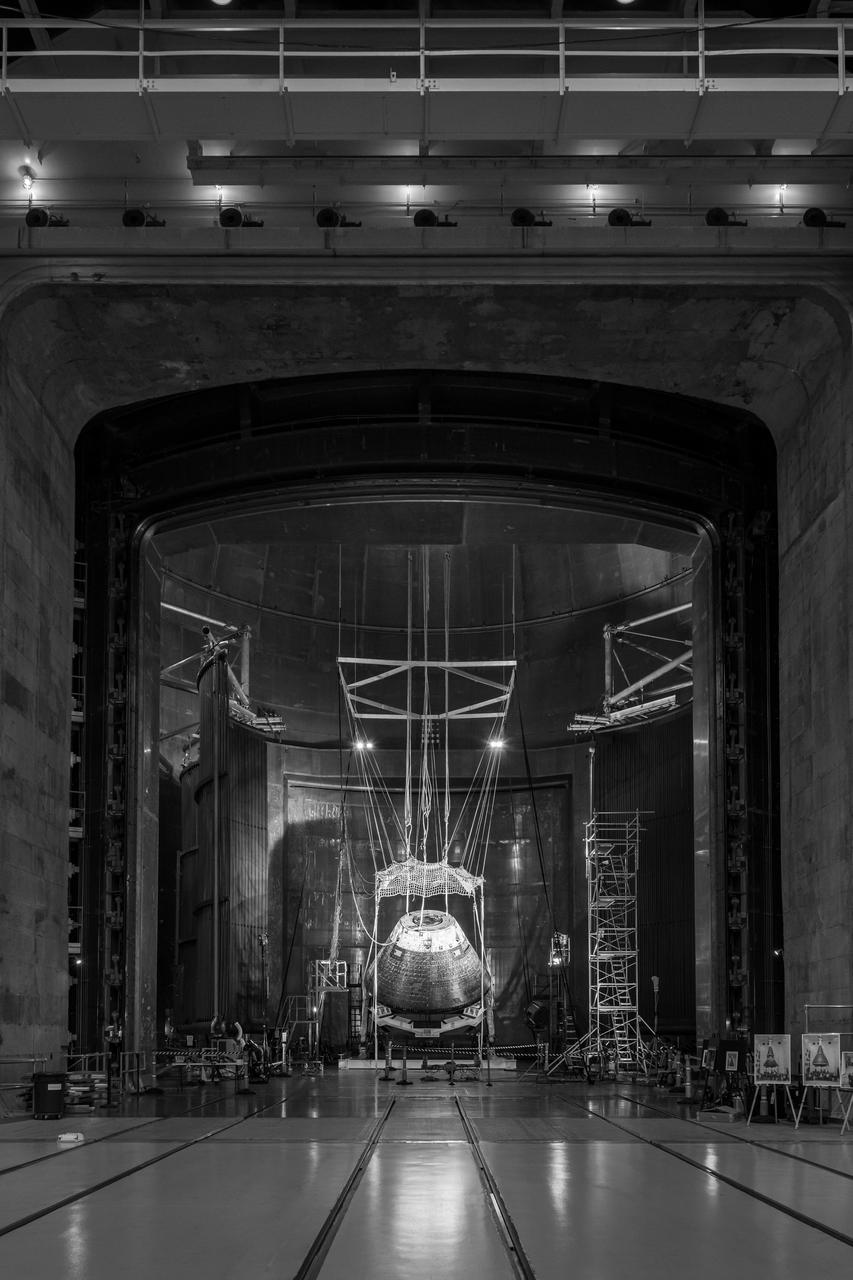
The Orion Crew Module, also known as the Orion Environmental Test Article (ETA), returned to NASA’s Neil Armstrong Test Facility in Sandusky, Ohio, in January 2024 and completed an 11-month test campaign necessary for the safety and success of Artemis II. In November 2024, experts completed the Forward Bay Cover jettison test, which is the last piece that must eject right before parachutes deploy. This image shows the setup right before the FBC deployment test. Photo Credit: (NASA/Jordan Salkin)
The Orion Crew Module, also known as the Orion Environmental Test Article (ETA), returned to NASA’s Neil Armstrong Test Facility in Sandusky, Ohio, in January 2024 and completed an 11-month test campaign necessary for the safety and success of Artemis II. In November 2024, experts completed the Forward Bay Cover jettison test, which is the last piece that must eject right before parachutes deploy. This image shows the setup right before the FBC deployment test. Photo Credit: (NASA/Jordan Salkin)
The Orion Crew Module, also known as the Orion Environmental Test Article (ETA), returned to NASA’s Neil Armstrong Test Facility in Sandusky, Ohio, in January 2024 and completed an 11-month test campaign necessary for the safety and success of Artemis II. In November 2024, experts completed the Forward Bay Cover jettison test, which is the last piece that must eject right before parachutes deploy. This image shows the setup right before the FBC deployment test. Photo Credit: (NASA/Jordan Salkin)
The Orion Crew Module, also known as the Orion Environmental Test Article (ETA), returned to NASA’s Neil Armstrong Test Facility in Sandusky, Ohio, in January 2024 and completed an 11-month test campaign necessary for the safety and success of Artemis II. In November 2024, experts completed the Forward Bay Cover jettison test, which is the last piece that must eject right before parachutes deploy. This image shows the setup right before the FBC deployment test. Photo Credit: (NASA/Jordan Salkin)
The Orion Crew Module, also known as the Orion Environmental Test Article (ETA), returned to NASA’s Neil Armstrong Test Facility in Sandusky, Ohio, in January 2024 and completed an 11-month test campaign necessary for the safety and success of Artemis II. In November 2024, experts completed the Forward Bay Cover jettison test, which is the last piece that must eject right before parachutes deploy. This image shows the setup right before the FBC deployment test. Photo Credit: (NASA/Jordan Salkin)
The Orion Crew Module, also known as the Orion Environmental Test Article (ETA), returned to NASA’s Neil Armstrong Test Facility in Sandusky, Ohio, in January 2024 and completed an 11-month test campaign necessary for the safety and success of Artemis II. In November 2024, experts completed the Forward Bay Cover jettison test, which is the last piece that must eject right before parachutes deploy. This image shows the setup right before the FBC deployment test. Photo Credit: (NASA/Jordan Salkin)

The Orion Crew Module, also known as the Orion Environmental Test Article (ETA), returned to NASA’s Neil Armstrong Test Facility in Sandusky, Ohio, in January 2024 and completed an 11-month test campaign necessary for the safety and success of Artemis II. In November 2024, experts completed the Forward Bay Cover jettison test, which is the last piece that must eject right before parachutes deploy. This image shows the setup right before the FBC deployment test. Photo Credit: (NASA/Jordan Salkin)
The Orion Crew Module, also known as the Orion Environmental Test Article (ETA), returned to NASA’s Neil Armstrong Test Facility in Sandusky, Ohio, in January 2024 and completed an 11-month test campaign necessary for the safety and success of Artemis II. In November 2024, experts completed the Forward Bay Cover jettison test, which is the last piece that must eject right before parachutes deploy. This image shows the setup right before the FBC deployment test. Photo Credit: (NASA/Jordan Salkin)
The Orion Crew Module, also known as the Orion Environmental Test Article (ETA), returned to NASA’s Neil Armstrong Test Facility in Sandusky, Ohio, in January 2024 and completed an 11-month test campaign necessary for the safety and success of Artemis II. In November 2024, experts completed the Forward Bay Cover jettison test, which is the last piece that must eject right before parachutes deploy. This image shows the setup right before the FBC deployment test. Photo Credit: (NASA/Jordan Salkin)
The Orion Crew Module, also known as the Orion Environmental Test Article (ETA), returned to NASA’s Neil Armstrong Test Facility in Sandusky, Ohio, in January 2024 and completed an 11-month test campaign necessary for the safety and success of Artemis II. In November 2024, experts completed the Forward Bay Cover jettison test, which is the last piece that must eject right before parachutes deploy. This image shows the setup right before the FBC deployment test. Photo Credit: (NASA/Jordan Salkin)
The Orion Crew Module, also known as the Orion Environmental Test Article (ETA), returned to NASA’s Neil Armstrong Test Facility in Sandusky, Ohio, in January 2024 and completed an 11-month test campaign necessary for the safety and success of Artemis II. In November 2024, experts completed the Forward Bay Cover jettison test, which is the last piece that must eject right before parachutes deploy. This image shows the setup right before the FBC deployment test. Photo Credit: (NASA/Jordan Salkin)
NATHAN HORACE STRONG (AEROSPACE ENGINEER, ER31 PROPULSION TURBOMACHINERY DESIGN & DEVELOPMENT BRANCH) AND NATHAN COFFEE (EM10 MATERIALS TEST ENGINEER, JACOBS ESTS GROUP/JTI) ADJUST A UNIQUE MECHANICAL TEST SETUP THAT MEASURES STRAIN ON A SINGLE SAMPLE, USING TWO DIFFERENT TECHNIQUES AT THE SAME TIME. THE TEST FIXTURE HOLDS A SPECIMEN THAT REPRESENTS A LIQUID OXYGEN (LOX) BEARING FROM THE J2-X ENGINE. COFFEY, AT RIGHT, WORK IN A LAB IN BUILDING 4612 ON A BEARING TEST
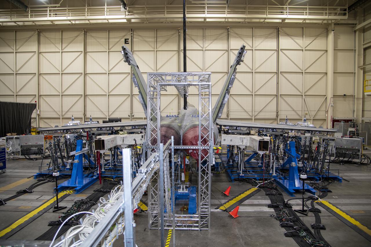
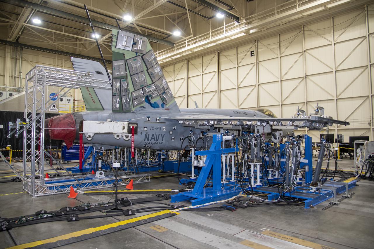
This rear view of the right wing load hardware shows the setup for testing a F/A-18E from the Naval Air Systems Command (NAVAIR) in Patuxent River, Maryland. The aircraft is in NASA's Armstrong Flight Research Center Flight Loads Laboratory in Edwards, California, for the center's biggest load calibrations tests. This testing is needed before the aircraft can serve as a test vehicle for determining if it can safely manage maneuvers and proposed upgrades.
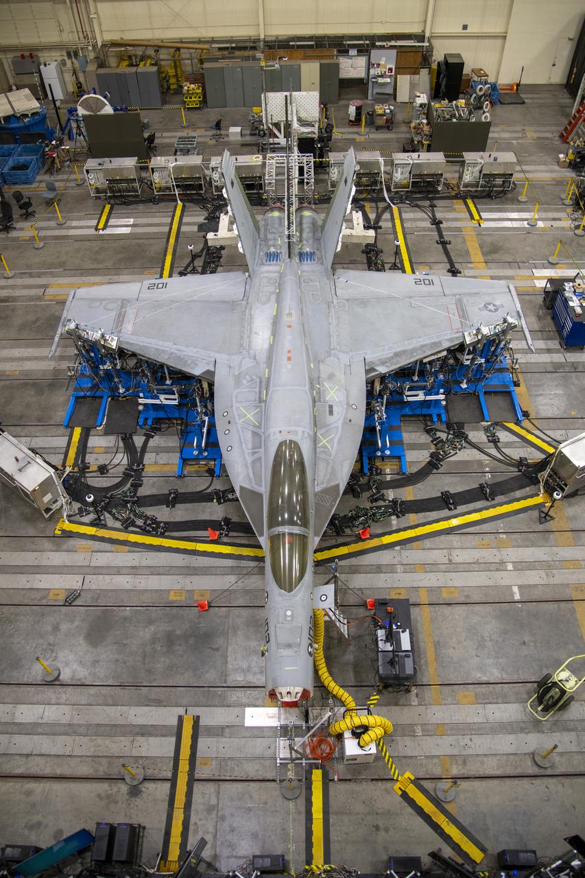
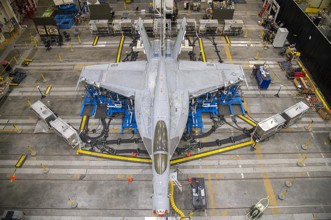
Wing load test hardware is setup under wing of a F/A-18E from the Naval Air Systems Command (NAVAIR) in Patuxent River, Maryland. The aircraft is in NASA’s Armstrong Flight Research Center Flight Loads Laboratory in Edwards, California, for the center’s biggest load calibrations tests. This testing is needed before the aircraft can serve as a test vehicle for determining if it can safely manage maneuvers and proposed upgrades.
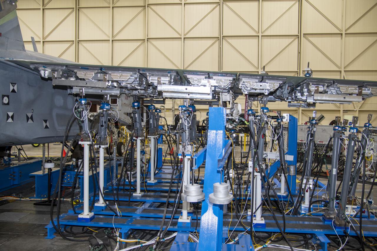
This rear view of the left wing load hardware shows the setup for testing a F/A-18E from the Naval Air Systems Command (NAVAIR) in Patuxent River, Maryland. The aircraft is in NASA's Armstrong Flight Research Center Flight Loads Laboratory in Edwards, California, for the center's biggest load calibrations tests. This testing is needed before the aircraft can serve as a test vehicle for determining if it can safely manage maneuvers and proposed upgrades.Â
Left wing load hardware is setup for testing a F/A-18E from the Naval Air Systems Command (NAVAIR) in Patuxent River, Maryland. The aircraft is in NASA's Armstrong Flight Research Center Flight Loads Laboratory in Edwards, California, for the center's biggest load calibrations tests. This testing is needed before the aircraft can serve as a test vehicle for determining if it can safely manage maneuvers and proposed upgrades.
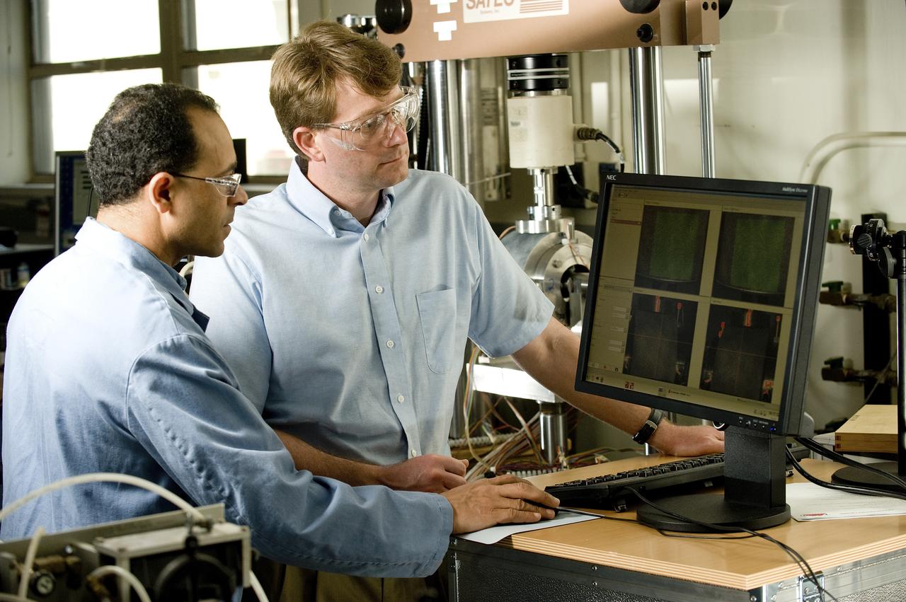
AYMAN GIRGIS (EM10 MATERIALS TEST ENGINEER, JACOBS ESTS GROUP/JTI) AND ERIC EARHART (AEROSPACE ENGINEER, ER41 PROPULSION STRUCTURAL & DYNAMICS ANALYSIS BRANCH) DISCUSS DATA PRODUCED BY A UNIQUE MECHANICAL TEST SETUP THAT MEASURES STRAIN ON A SINGLE SAMPLE, USING TWO DIFFERENT TECHNIQUES AT THE SAME TIME. THE TEST FIXTURE HOLDS A SPECIMEN THAT REPRESENTS A LIQUID OXYGEN (LOX) BEARING FROM THE J2-X ENGINE.
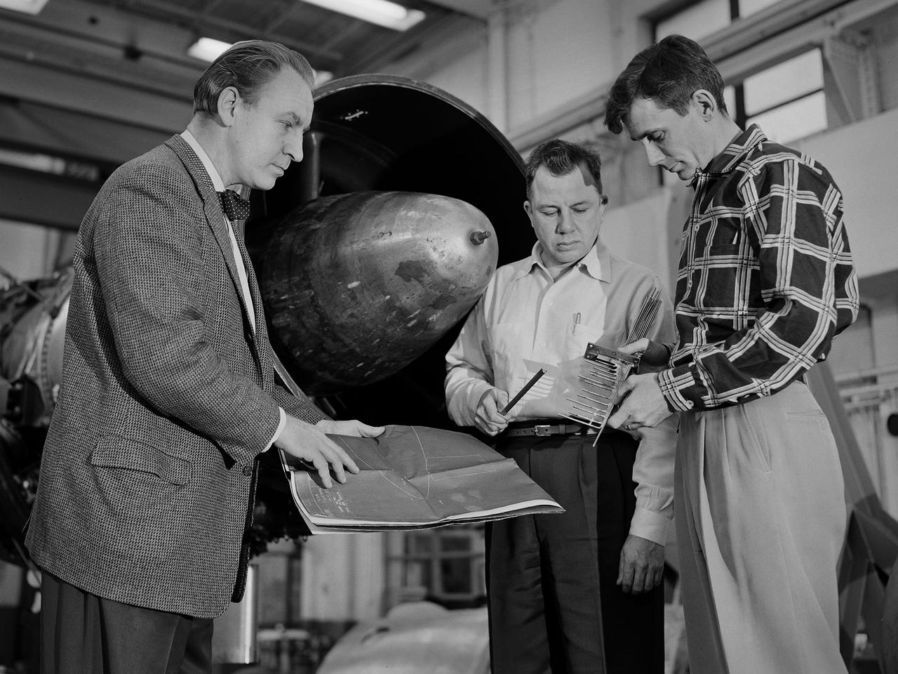
Researcher Bill Reiwaldt discusses the preparations for a test in the Altitude Wind Tunnel with technicians Jack Wagner and Dick Golladay at the National Advisory Committee for Aeronautics (NACA) Lewis Flight Propulsion Laboratory. Research engineers developed ideas for tests that were often in response to requests from the military or aircraft industry. Arrangements were made to obtain an engine for the study and to transport it to the Cleveland laboratory. The engine was brought into the facility’s shop area, where it was readied for investigation. It was common for several different engines to be worked on simultaneously in the shop. The researcher would discuss the engine and the test objectives with the Test Installation Division and the facility’s technicians. The operations team would handle the installation of the instrumentation and fitting the test into the facility’s schedule. Upon completion of the previous test, the engine was removed. The next engine was lifted by an overhead crane and transported from the shop to the test section. The engine was connected to the measurement devices and fuel and oil supply lines. Engines were tested over numerous runs under varying conditions and with variations on the configuration. The findings and test procedure were then described in research or technical memorandums and distributed to industry.

Technicians set up test hardware inside the test section of the Icing Research Tunnel at the National Aeronautics and Space Administration (NASA) Lewis Research Center. The Icing Research Tunnel was built in the early 1940s to study the formation of ice on aircraft surfaces and develop methods of preventing or eradicating that ice. Ice buildup is dangerous because it adds extra weight, effects aerodynamics, and sometimes blocks air flow through engines. The Icing Research Tunnel is a closed-loop atmospheric wind tunnel with a 6- by 9-foot test section. The tunnel can produce speeds up to 300 miles per hour and temperatures from 30 to -45 °F. NACA engineers struggled initially to perfect a spray bar system to introduce moisture into the airstream. The tunnel was shut down in the late 1950s as the center focused its energy exclusively on space. Industrial customers began using the tunnel sporadically, then steadily, in the 1960s. Boeing, Aerojet, Lockheed, Sikorsky, Beech and others ran tests during the 1960s. Boeing analyzed engine inlets for the CH-47 Chinook, CH-46 (Sea Knight) and CH-113. This photograph was taken during a series of 100 ice-phobic coatings for the Federal Aviation Administration. They found that many of the coatings reduced ice adhesion to the test sample, but they could not be used for aircraft applications.
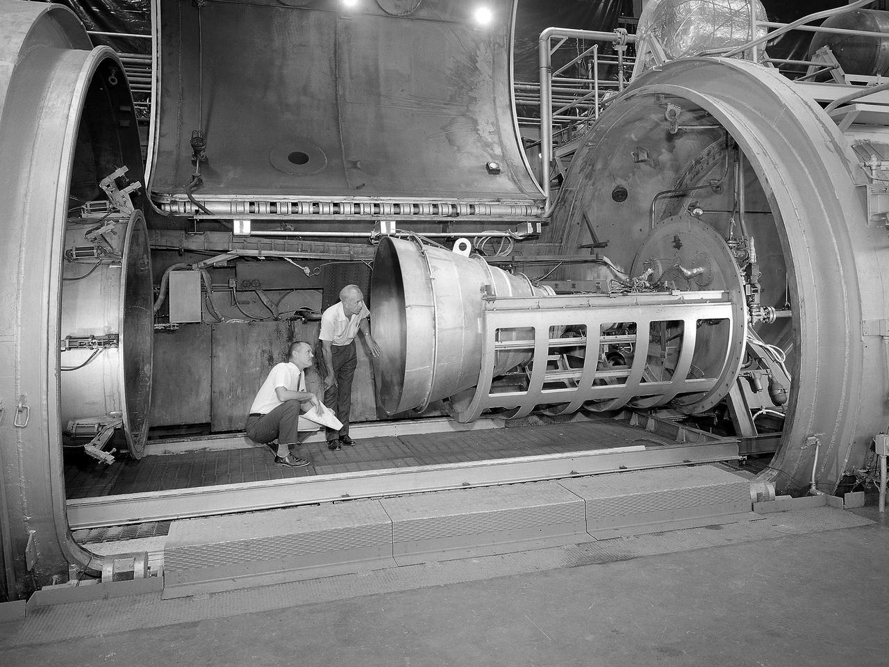
Bill Harrison and Bud Meilander check the setup of an Apollo Contour rocket nozzle in the Propulsion Systems Laboratory at the National Aeronautics and Space Administration (NASA) Lewis Research Center. The Propulsion Systems Laboratory contained two 14-foot diameter test chambers that could simulate conditions found at very high altitudes. The facility was used in the 1960s to study complex rocket engines such as the Pratt and Whitney RL-10 and rocket components such as the Apollo Contour nozzle, seen here. Meilander oversaw the facility’s mechanics and the installation of test articles into the chambers. Harrison was head of the Supersonic Tunnels Branch in the Test Installations Division. Researchers sought to determine the impulse value of the storable propellant mix, classify and improve the internal engine performance, and compare the results with analytical tools. A special setup was installed in the chamber that included a device to measure the thrust load and a calibration stand. Both cylindrical and conical combustion chambers were examined with the conical large area ratio nozzles. In addition, two contour nozzles were tested, one based on the Apollo Service Propulsion System and the other on the Air Force’s Titan transtage engine. Three types of injectors were investigated, including a Lewis-designed model that produced 98-percent efficiency. It was determined that combustion instability did not affect the nozzle performance. Although much valuable information was obtained during the tests, attempts to improve the engine performance were not successful.
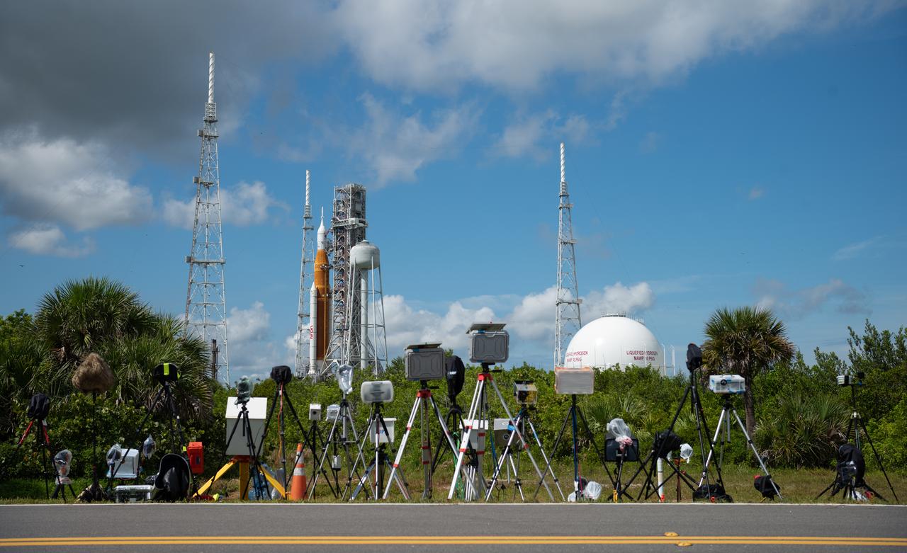
Cameras belonging to members of the media are seen setup to photograph the launch of NASA’s Space Launch System (SLS) rocket with the Orion spacecraft aboard at Launch Pad 39B, Saturday, Aug. 27, 2022, at NASA’s Kennedy Space Center in Florida. NASA’s Artemis I flight test is the first integrated test of the agency’s deep space exploration systems: the Orion spacecraft, SLS rocket, and supporting ground systems. Launch of the uncrewed flight test is targeted for no earlier than Aug. 29 at 8:33 a.m. ET. Photo Credit: (NASA/Joel Kowsky)

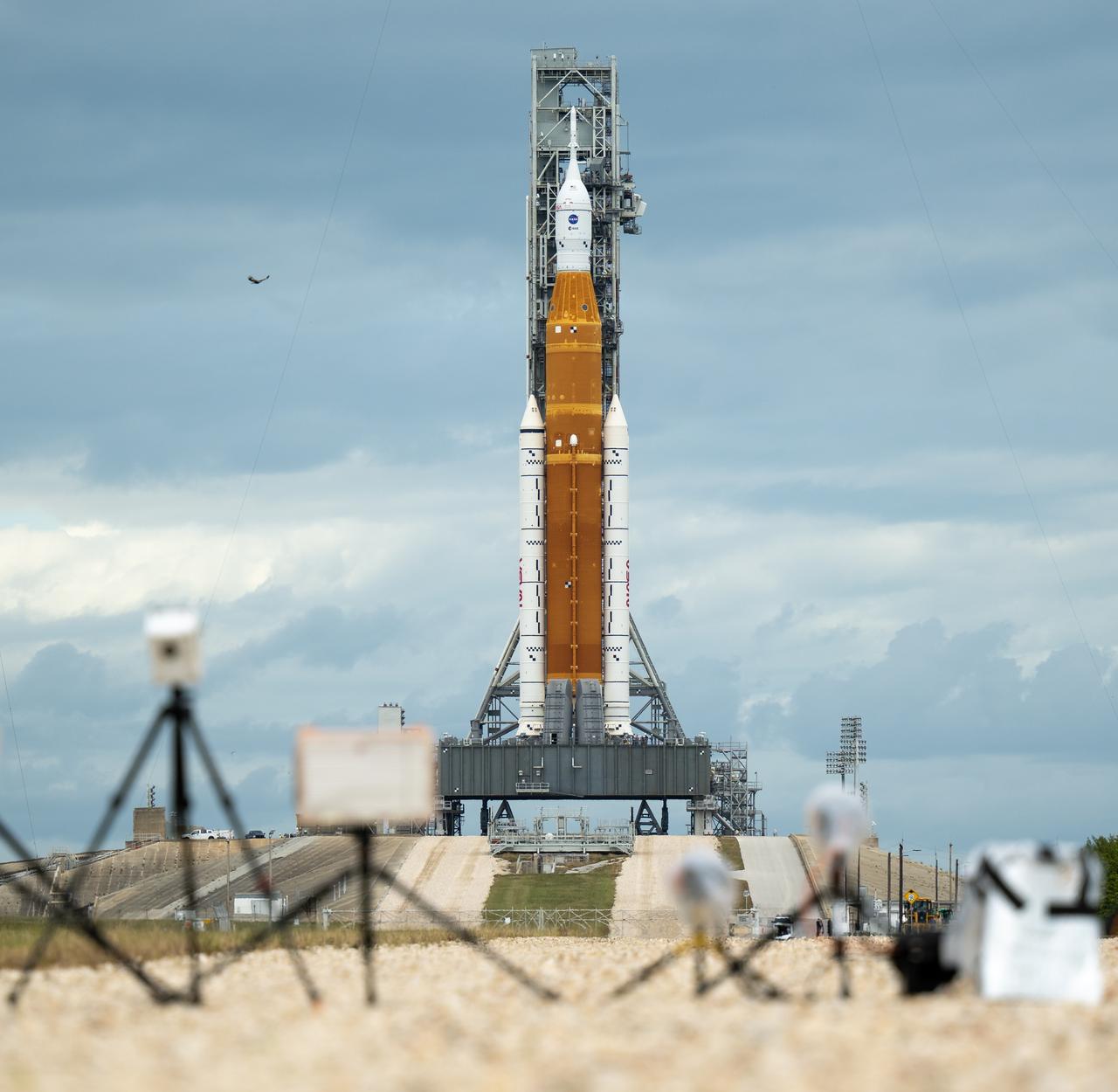
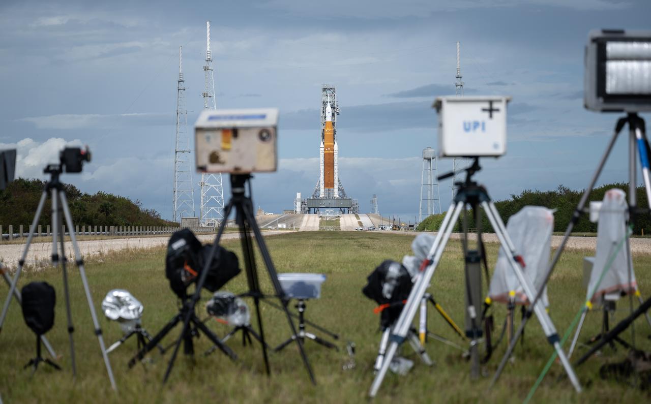
Media remote cameras are setup outside Launch Pad 39B and aimed at NASA’s Space Launch System (SLS) rocket with the Orion spacecraft aboard as preparations for launch continue, Sunday, Nov. 13, 2022, at NASA’s Kennedy Space Center in Florida. NASA’s Artemis I flight test is the first integrated test of the agency’s deep space exploration systems: the Orion spacecraft, SLS rocket, and supporting ground systems. Launch of the uncrewed flight test is targeted for no earlier than Nov. 16 at 1:04 a.m. EST. Photo Credit: (NASA/Bill Ingalls)
Media remote cameras are setup outside Launch Pad 39B and aimed at NASA’s Space Launch System (SLS) rocket with the Orion spacecraft aboard as preparations for launch continue, Sunday, Nov. 13, 2022, at NASA’s Kennedy Space Center in Florida. NASA’s Artemis I flight test is the first integrated test of the agency’s deep space exploration systems: the Orion spacecraft, SLS rocket, and supporting ground systems. Launch of the uncrewed flight test is targeted for no earlier than Nov. 16 at 1:04 a.m. EST. Photo Credit: (NASA/Bill Ingalls)
Media remote cameras are setup outside Launch Pad 39B and aimed at NASA’s Space Launch System (SLS) rocket with the Orion spacecraft aboard as preparations for launch continue, Sunday, Nov. 13, 2022, at NASA’s Kennedy Space Center in Florida. NASA’s Artemis I flight test is the first integrated test of the agency’s deep space exploration systems: the Orion spacecraft, SLS rocket, and supporting ground systems. Launch of the uncrewed flight test is targeted for no earlier than Nov. 16 at 1:04 a.m. EST. Photo Credit: (NASA/Bill Ingalls)

ISS049e011638 (09/27/2016) --- Expedition 49 crewmember Takuya Onishi of JAXA works on the setup of the Group Combustion Module (GCM) inside the Japanese Experiment Module. The GCM will be used to house the Group Combustion experiment from the Japan Aerospace Exploration Agency (JAXA) to test a theory that fuel sprays change from partial to group combustion as flames spread across a cloud of droplets.
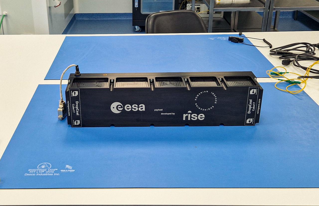
jsc2024e068511 (7/24/2024) --- Setup for Investigation of Drops Coalescence in View of Medical Applications (DropCoal) (ICE Cubes #17 - DropCoal) fully integrated, before performing the mechanical, electrical, and software interface tests at Space Application Services. An ICE Cubes Facility engineering model was used, identical to the one installed on the International Space Station. Image courtesy of Romanian InSpace Engineering.
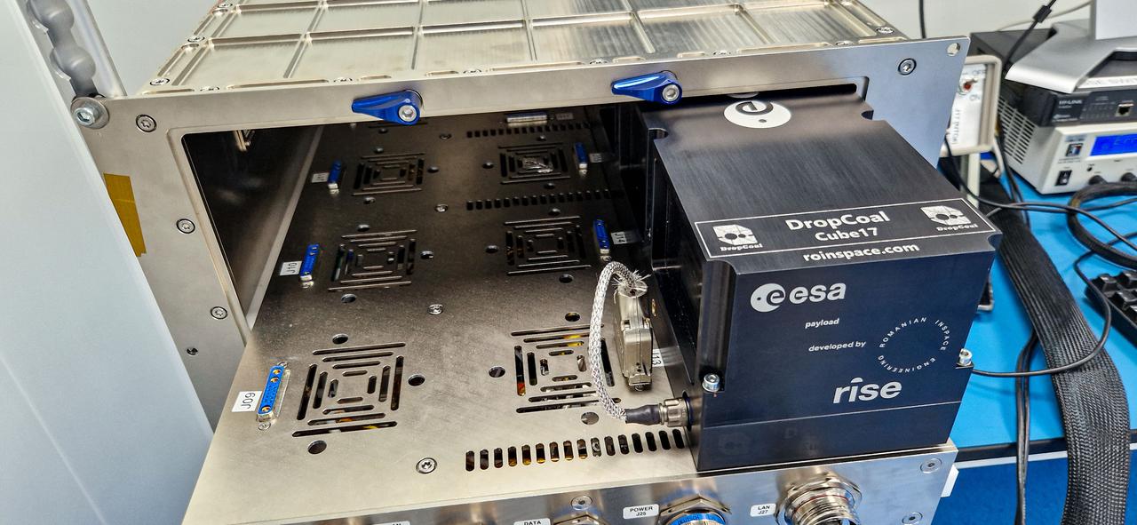
jsc2024e068512 (7/24/2024) --- Setup for Investigation of Drops Coalescence in View of Medical Applications (DropCoal) (ICE Cubes #17 - DropCoal) during the Interface test, integrated into the ICE Cubes Facility engineering model (EM) at Space Application Services (SAS) premises in Brussels. The investigation studies how water and ethanol droplets of various sizes behave when colliding at different velocities. Image courtesy of Romanian InSpace Engineering.
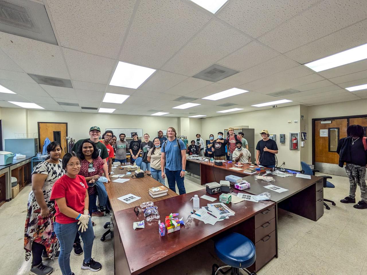
jsc2025e064334 (7/22/2025) --- This hands-on demonstration illustrated how different materials respond to different gravitational forces and their effects on flexural strength. Students engaged in experiments using models and simple testing setups to simulate the impacts of gravitational variations on material behavior. The activity allowed participants to compare how certain materials deform, crack, or maintain their structural integrity. By observing these differences, students gained a clearer understanding of how researchers design and optimize materials for use in extreme environments, such as space or high-stress industrial applications.
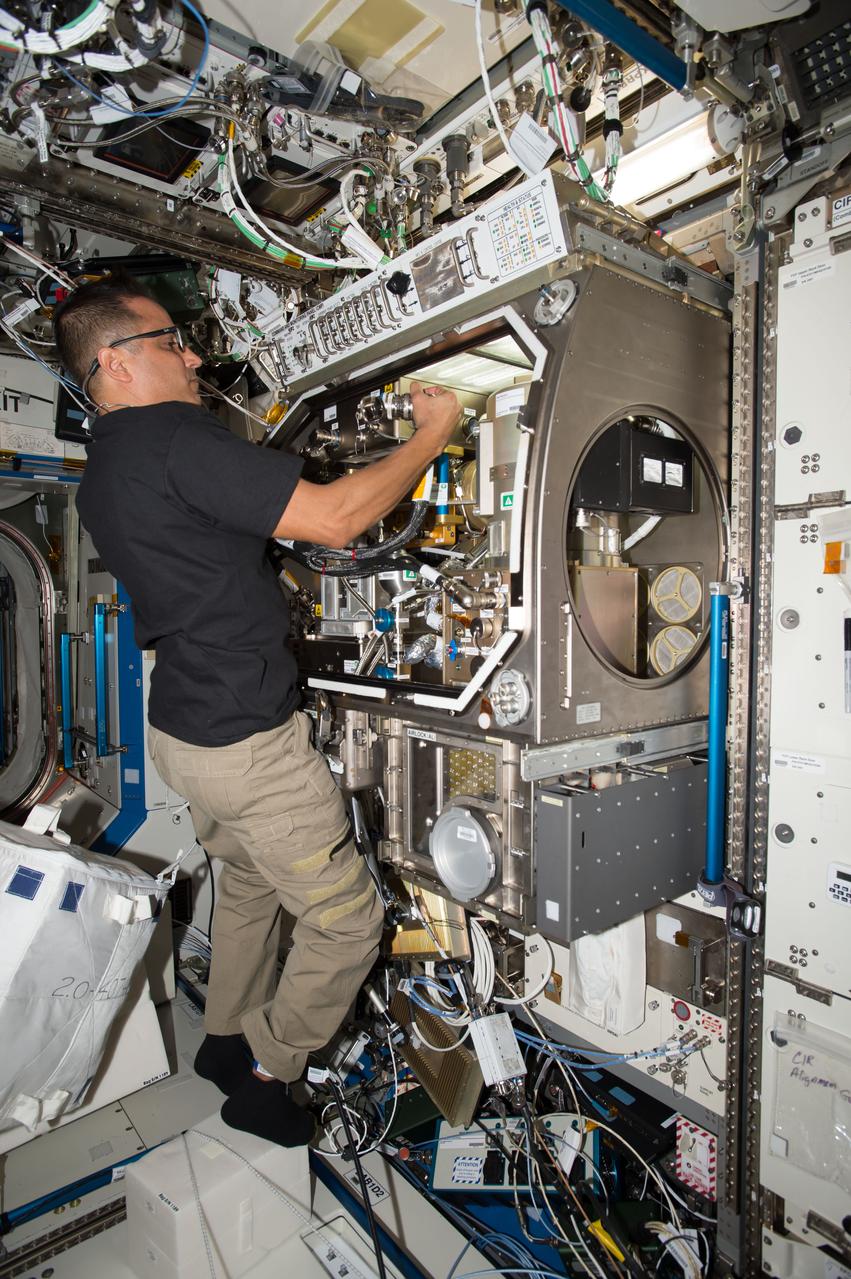
iss053e027113 (9/18/2017) --- NASA astronaut Joe Acaba during the Zero Boil-Off Tank Hardware Setup in the Microgravity Science Glovebox (MSG). Zero Boil-Off Tank (ZBOT) uses an experimental fluid to test active heat removal and forced jet mixing as alternative means for controlling tank pressure for volatile fluids. Results from the investigation improve models used to design tanks for long-term cryogenic liquid storage, which are essential in biotechnology, medicine, industrial, and many other applications on Earth.
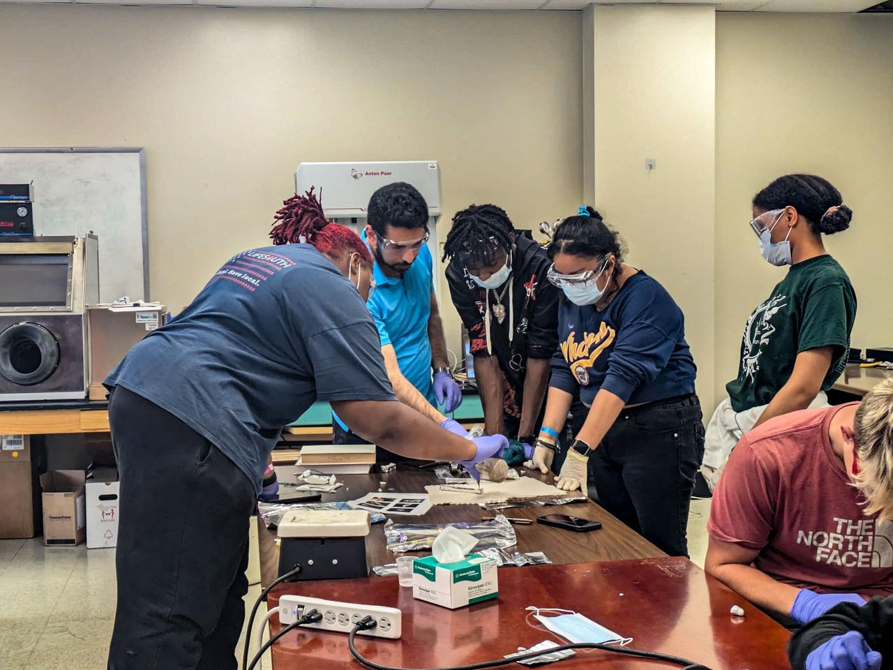
jsc2025e064335 (7/22/2025) --- This hands-on demonstration illustrated how different materials respond to different gravitational forces and their effects on flexural strength. Students engaged in experiments using models and simple testing setups to simulate the impacts of gravitational variations on material behavior. The activity allowed participants to compare how certain materials deform, crack, or maintain their structural integrity. By observing these differences, students gained a clearer understanding of how researchers design and optimize materials for use in extreme environments, such as space or high-stress industrial applications.
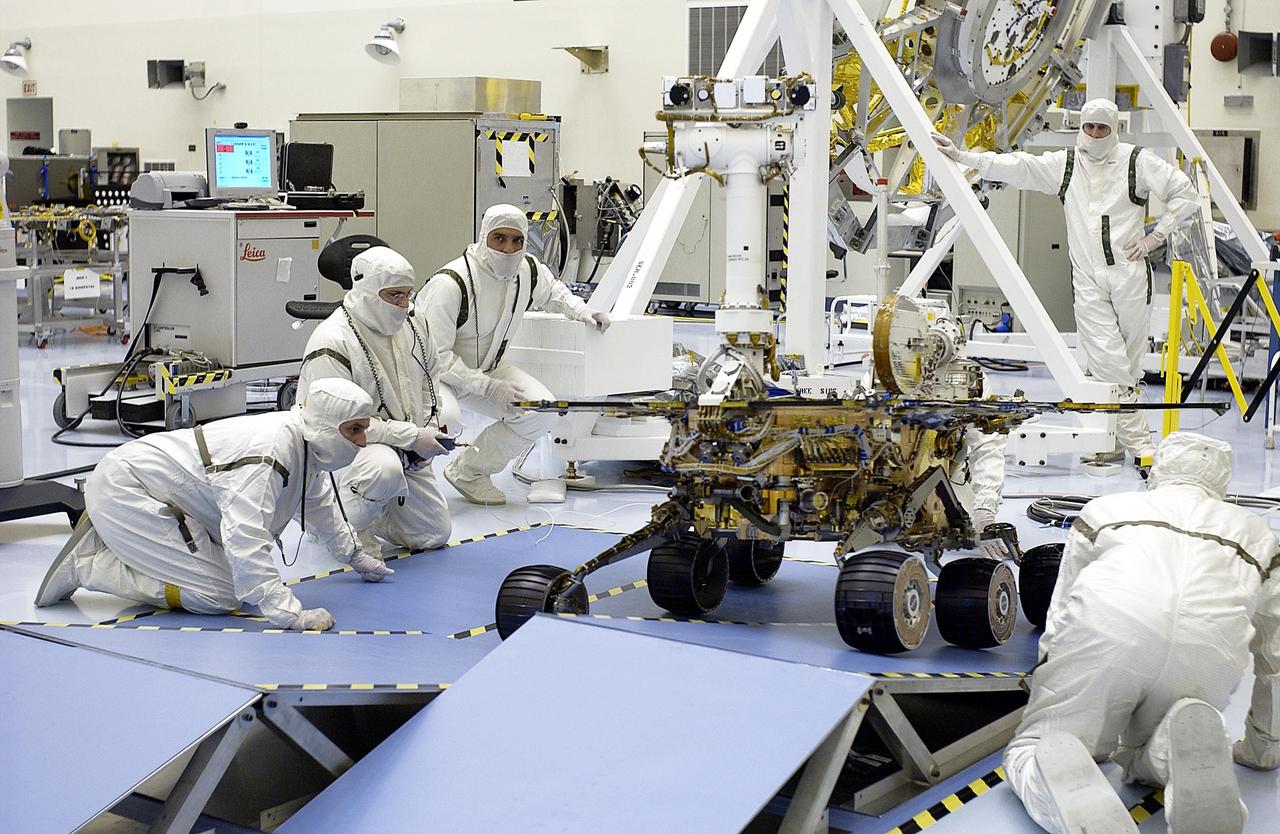
KENNEDY SPACE CENTER, FLA. -- In the Payload Hazardous Servicing Facility, the Mars Exploration Rover-2 (MER-2) is tested for mobility and maneuverability over a setup of ramps. Set to launch in Spring 2003, the MER Mission will consist of two identical rovers designed to cover roughly 110 yards each Martian day over various terrain. Each rover will carry five scientific instruments that will allow it to search for evidence of liquid water that may have been present in the planet's past. The rovers will be identical to each other, but will land at different regions of Mars. The first rover has a launch window opening May 30, and the second rover a window opening June 25.
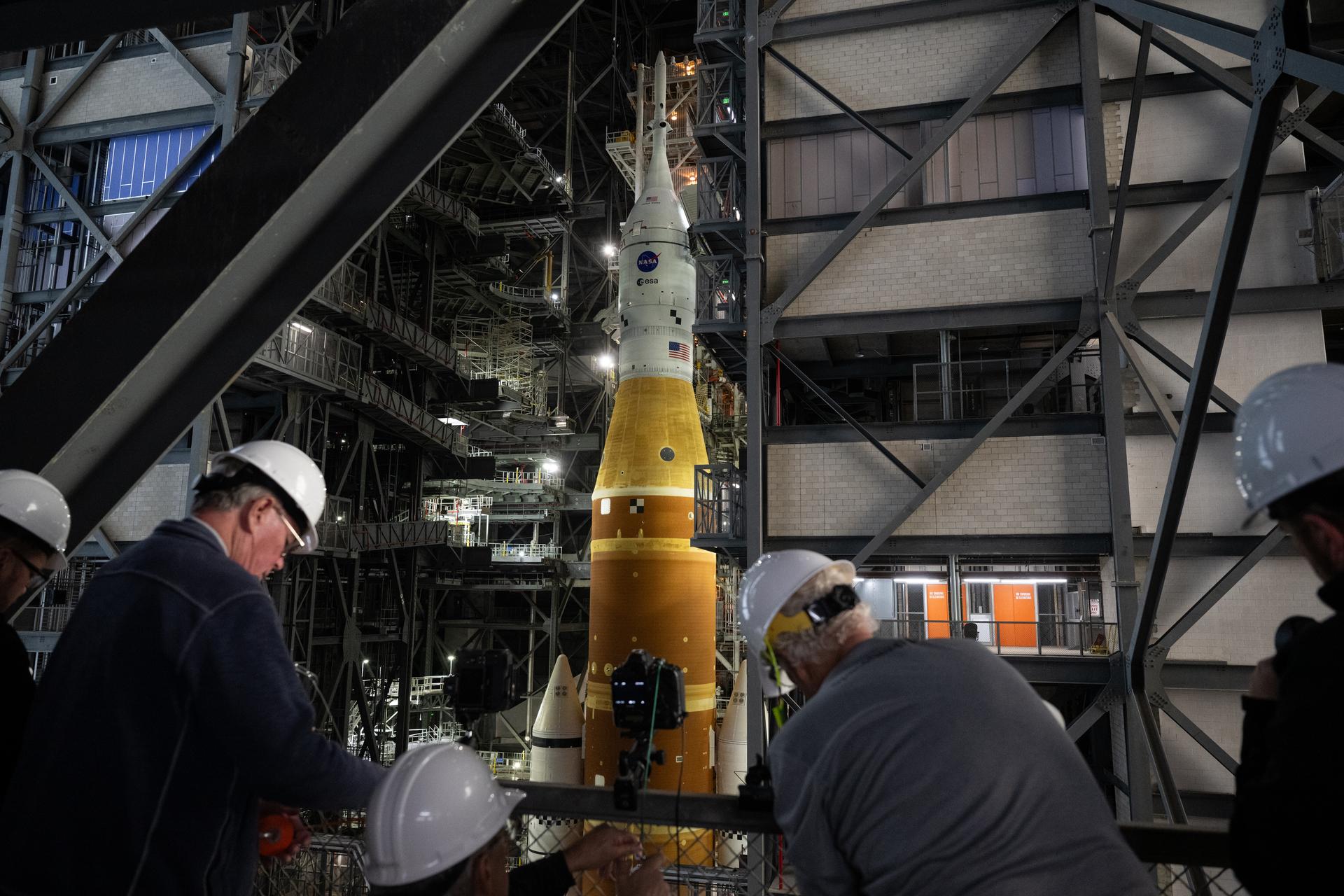
Members of the media are seen as they setup remote cameras to photograph the rollout of NASA’s Artemis II SLS (Space Launch System) rocket and Orion spacecraft inside the Vehicle Assembly building as preparations continue for rollout to Launch Pad 39B, Friday, Jan. 16, 2026, at NASA’s Kennedy Space Center in Florida. NASA’s Artemis II flight test will take Commander Reid Wiseman, Pilot Victor Glover, and Mission Specialist Christina Koch from NASA, and Mission Specialist Jeremy Hansen from the CSA (Canadian Space Agency), around the Moon and back to Earth no later than April 2026. Photo Credit: (NASA/Joel Kowsky)
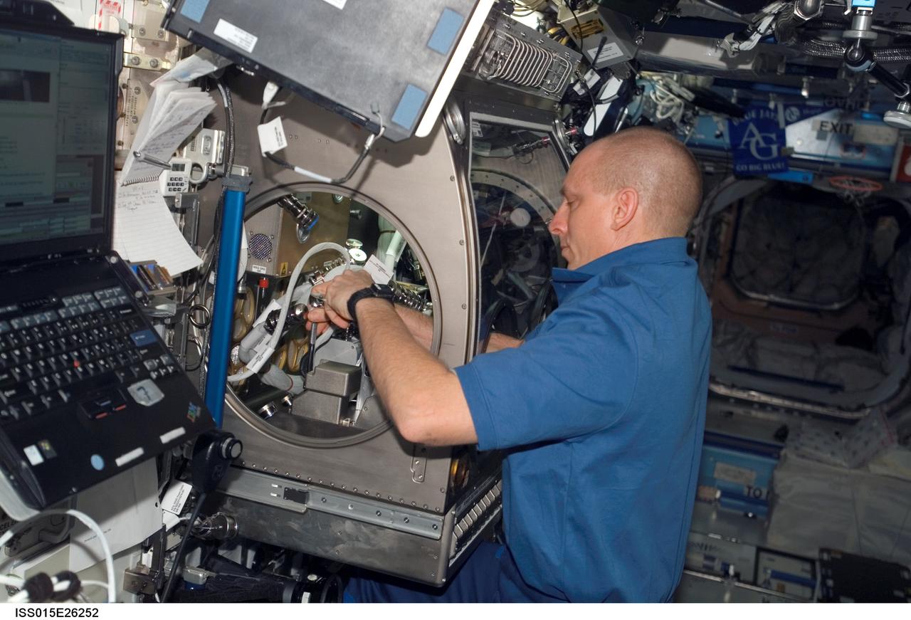
ISS015-E-26252 (1 Sept. 2007) --- Astronaut Clay Anderson, Expedition 15 flight engineer, works on the Smoke and Aerosol Measurement Experiment (SAME) hardware setup located in the Microgravity Science Glovebox (MSG) in the Destiny laboratory of the International Space Station. SAME will measure the smoke properties, or particle size distribution, of typical particles that are produced from different materials that can be found onboard station and other spacecrafts. SAME aims to test the performance of ionization smoke detectors and evaluate the performance of the photoelectric smoke detectors. The data will be used to develop a model that can predict smoke droplet growth that will be used to evaluate future smoke detection devices.
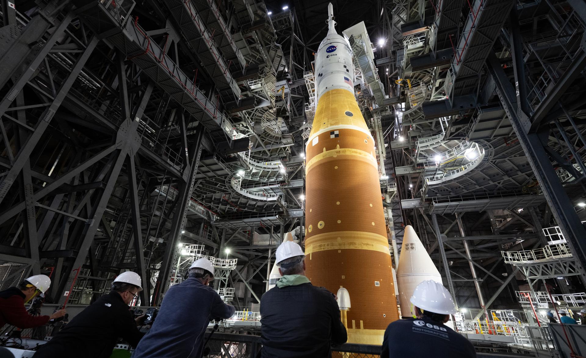
Members of the media are seen as they setup remote cameras to photograph the rollout of NASA’s Artemis II SLS (Space Launch System) rocket and Orion spacecraft inside the Vehicle Assembly building as preparations continue for rollout to Launch Pad 39B, Friday, Jan. 16, 2026, at NASA’s Kennedy Space Center in Florida. NASA’s Artemis II flight test will take Commander Reid Wiseman, Pilot Victor Glover, and Mission Specialist Christina Koch from NASA, and Mission Specialist Jeremy Hansen from the CSA (Canadian Space Agency), around the Moon and back to Earth no later than April 2026. Photo Credit: (NASA/Joel Kowsky)

NASA’s Space Launch System (SLS) rocket with the Orion spacecraft aboard is seen atop a mobile launcher in High Bay 3 of the Vehicle Assembly Building as members of the media setup remote cameras to capture the first rollout to Launch Complex 39B, Wednesday, March 16, 2022, at NASA’s Kennedy Space Center in Florida. Ahead of NASA’s Artemis I flight test, the fully stacked and integrated SLS rocket and Orion spacecraft will undergo a wet dress rehearsal at Launch Complex 39B to verify systems and practice countdown procedures for the first launch. Photo Credit: (NASA/Joel Kowsky)
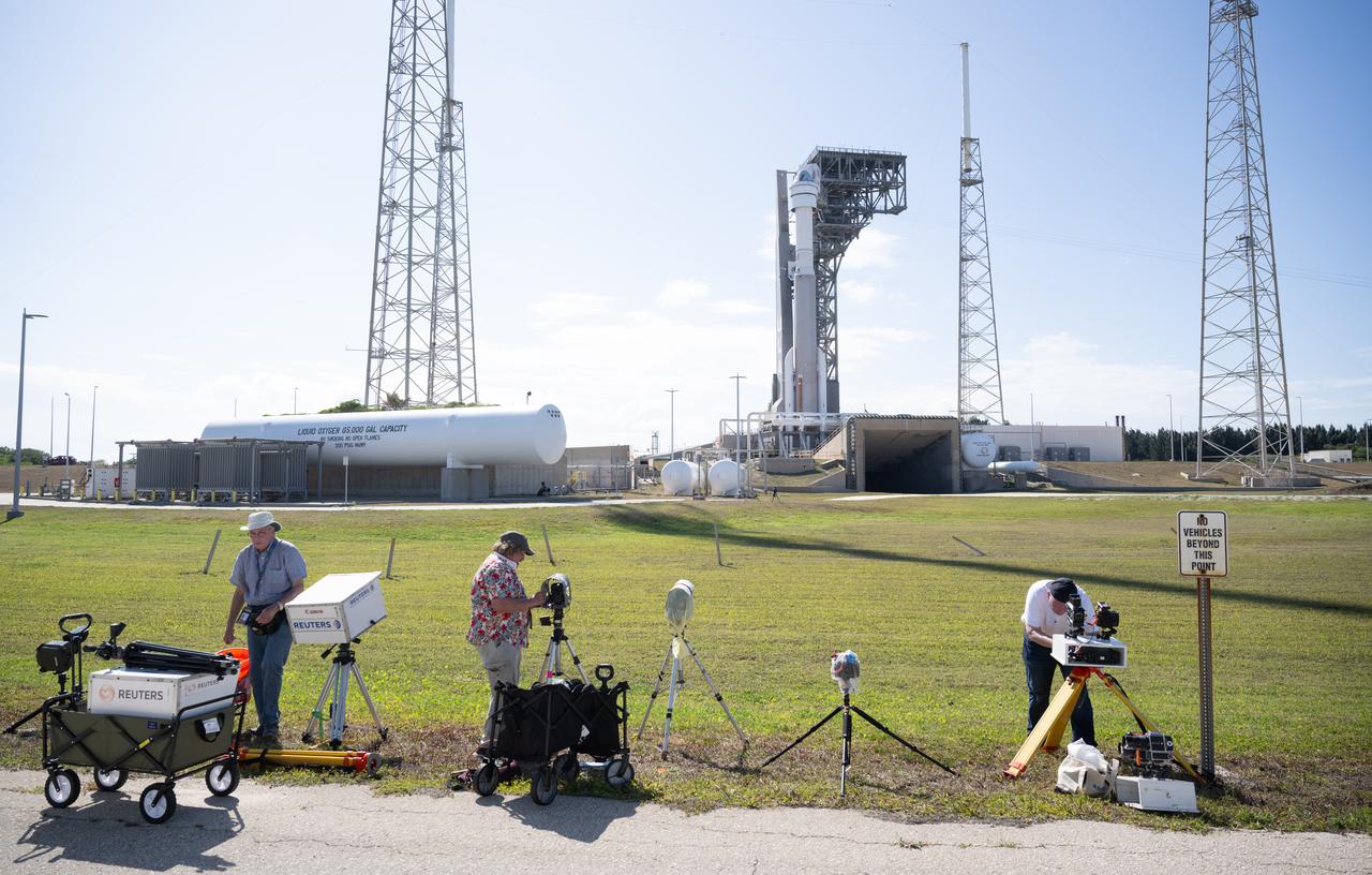
A United Launch Alliance Atlas V rocket with Boeing’s CST-100 Starliner spacecraft aboard is seen on the launch pad at Space Launch Complex 41 as members of the media setup remote cameras ahead of the NASA’s Boeing Crew Flight Test, Sunday, May 5, 2024 at Cape Canaveral Space Force Station in Florida. NASA’s Boeing Crew Flight Test is the first launch with astronauts of the Boeing CFT-100 spacecraft and United Launch Alliance Atlas V rocket to the International Space Station as part of the agency’s Commercial Crew Program. The flight test, targeted for launch at 10:34 p.m. EDT on Monday, May 6, serves as an end-to-end demonstration of Boeing’s crew transportation system and will carry NASA astronauts Butch Wilmore and Suni Williams to and from the orbiting laboratory. Photo Credit: (NASA/Joel Kowsky)
NASA’s Armstrong Flight Research Center Flight Loads Laboratory in Edwards, California, is working on one of its biggest load calibrations tests on an F/A-18E Super Hornet from the Naval Air Systems Command (NAVAIR) in Patuxent River, Maryland. This testing is needed before the aircraft can serve as a test vehicle for determining if it can safely manage maneuvers and proposed upgrades. The horizontal tail spindle testing, the first of three phases, wrapped up in October 2021. The next phase focuses on wing loads testing that is set to begin in December 2021.
NASA’s Armstrong Flight Research Center Flight Loads Laboratory in Edwards, California, is working on one of its biggest load calibrations tests on an F/A-18E Super Hornet from the Naval Air Systems Command (NAVAIR) in Patuxent River, Maryland. This testing is needed before the aircraft can serve as a test vehicle for determining if it can safely manage maneuvers and proposed upgrades. The horizontal tail spindle testing, the first of three phases, wrapped up in October 2021. The next phase focuses on wing loads testing that is set to begin in December 2021.

NASA’s Armstrong Flight Research Center Flight Loads Laboratory in Edwards, California, is working on one of its biggest load calibrations tests on an F/A-18E Super Hornet from the Naval Air Systems Command (NAVAIR) in Patuxent River, Maryland. This testing is needed before the aircraft can serve as a test vehicle for determining if it can safely manage maneuvers and proposed upgrades. The horizontal tail spindle testing, the first of three phases, wrapped up in October 2021. The next phase focuses on wing loads testing that is set to begin in December 2021.
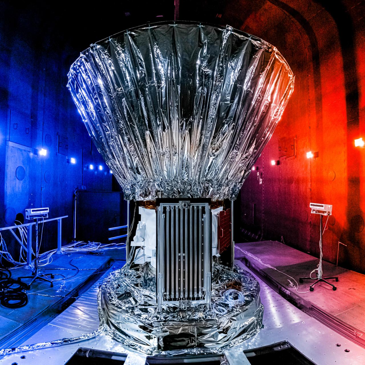
NASA's SPHEREx observatory is installed in the Titan Thermal Vacuum (TVAC) test Chamber at BAE Systems in Boulder, Colorado, in June 2024. As part of the test setup, the spacecraft and photon shield are covered in multilayer insulation and blankets and surrounded by ground support equipment. Short for Spectro-Photometer for the History of the Universe, Epoch of Reionization and Ices Explorer, SPHEREx will create a map of the cosmos like no other. Using a technique called spectroscopy to image the entire sky in 102 wavelengths of infrared light, SPHEREx will gather information about the composition of and distance to millions of galaxies and stars. With this map, scientists will study what happened in the first fraction of a second after the big bang, how galaxies formed and evolved, and the origins of water in planetary systems in our galaxy. https://photojournal.jpl.nasa.gov/catalog/PIA26541
Researchers check the setup of a multi-nozzle base flow model in the 10- by 10-Foot Supersonic Wind Tunnel at the National Aeronautics and Space Administration (NASA) Lewis Research Center. NASA researchers were struggling to understand the complex flow phenomena resulting from the use of multiple rocket engines. Robert Wasko and Theodore Cover of the Advanced Development and Evaluation Division’s analysis and operations sections conducted a set of tests in the 10- by 10 tunnel to further understand the flow issues. The Lewis researchers studied four and five-nozzle configurations in the 10- by 10 at simulated altitudes from 60,000 to 200,000 feet. The nozzles were gimbaled during some of the test runs to simulate steering. The flow field for the four-nozzle clusters was surveyed in the center and the lateral areas between the nozzles, whereas the five-nozzle cluster was surveyed in the lateral area only.
Engineer Frank Kutina and a National Aeronautics and Space Administration (NASA) mechanic examine the setup of an advanced combustor rig inside one of the test cells at the Lewis Research Center’s Four Burner Area in the Engine Research Building. Kutina, of the Research Operations Branch, served as go-between for the researchers and the mechanics. He helped develop the test configurations and get the hardware installed. At the time of this photograph, Lewis Center Director Abe Silverstein had just established the Airbreathing Engine Division to address the new propulsion of the 1960s. After nearly a decade of focusing almost exclusively on space, NASA Lewis began tackling issues relating to the new turbofan engine, noise reduction, energy efficiency, supersonic transport, and the never-ending quest for higher performance levels with smaller and more lightweight engines. The Airbreathing Engine Division’s Combustion Branch was dedicated to the study and mitigation of the high temperatures and pressures found in advanced combustor designs. These high temperatures and pressures could destroy engine components. The Lewis investigation included film cooling, diffuser flow, and jet mixing. Components were tested in smaller test cells, but a full-scale augmenting burner rig, seen here, was tested extensively in the Four Burner Area test cell.
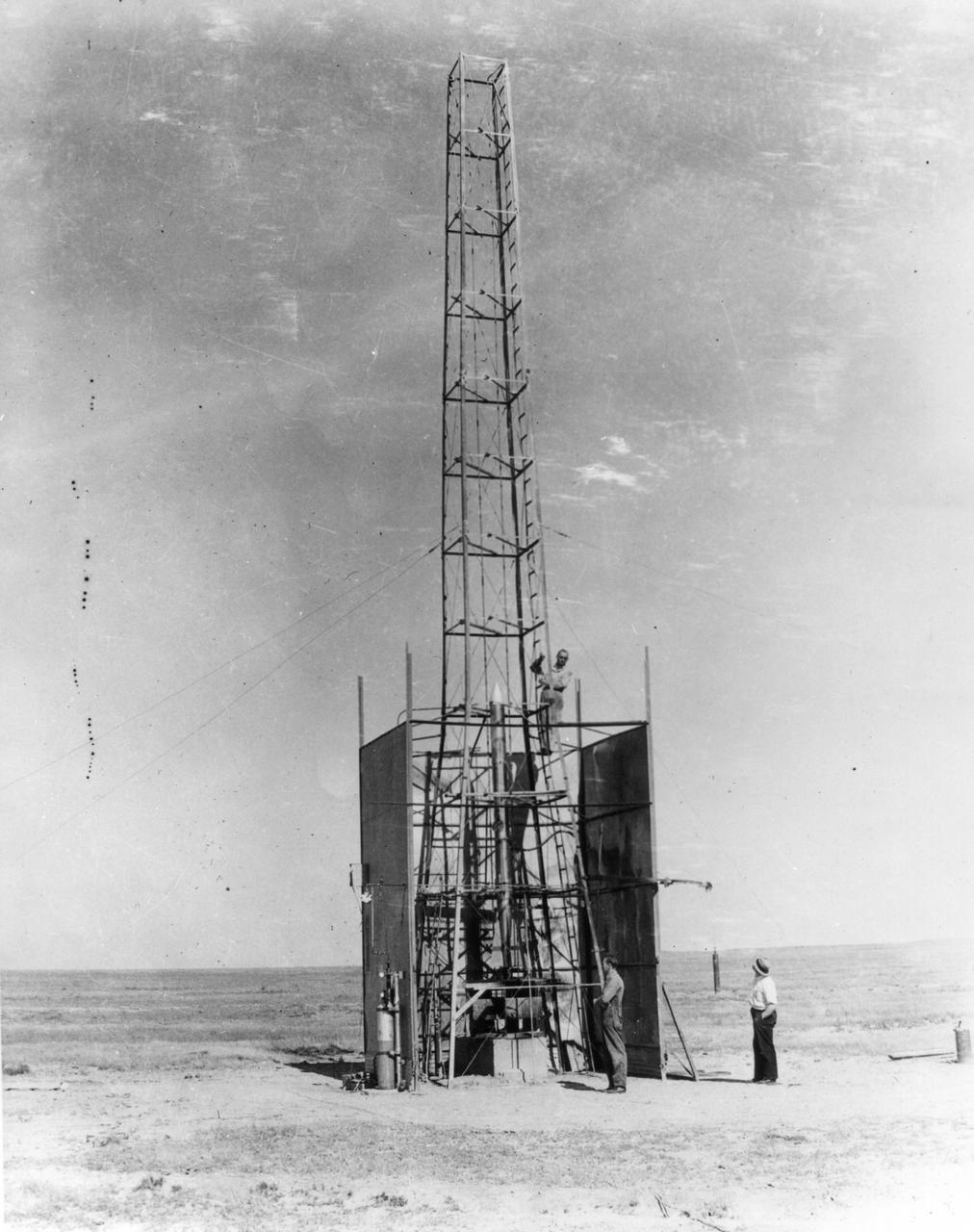
New Mexico -- Dr. Robert Goddard's rocket is being setup for the test that took place on October 29, 1935. It was a good flight. The rocket rose 4,000 feet--time in seconds. <b><a href="http://www.nasa.gov/centers/goddard/home/index.html" rel="nofollow">NASA Goddard Space Flight Center</a></b> enables NASA’s mission through four scientific endeavors: Earth Science, Heliophysics, Solar System Exploration, and Astrophysics. Goddard plays a leading role in NASA’s accomplishments by contributing compelling scientific knowledge to advance the Agency’s mission. <b>Follow us on <a href="http://twitter.com/NASA_GoddardPix" rel="nofollow">Twitter</a></b> <b>Join us on <a href="http://www.facebook.com/pages/Greenbelt-MD/NASA-Goddard/395013845897?ref=tsd" rel="nofollow">Facebook</a></b>
Setup of a Surveyor/Atlas/Centaur shroud in the Space Power Chambers for a leak test at the National Aeronautics and Space Administration (NASA) Lewis Research Center. Centaur was a 15,000-pound thrust second-stage rocket designed for the military in 1957 and 1958 by General Dynamics. It was the first major rocket to use the liquid hydrogen technology developed by Lewis in the 1950s. The Centaur Program suffered numerous problems before being transferred to Lewis in 1962. Several test facilities at Lewis’ main campus and Plum Brook Station were built or modified specifically for Centaur, including the Space Power Chambers. In 1961, NASA Lewis management decided to convert its Altitude Wind Tunnel into two large test chambers and later renamed it the Space Power Chambers. The conversion, which took over 2 years, included the removal of the tunnel’s internal components and insertion of bulkheads to seal off the new chambers. The larger chamber, seen here, could simulate altitudes of 100,000 feet. It was used for Centaur shroud separation and propellant management studies until the early 1970s. The leak test in this photograph was likely an attempt to verify that the shroud’s honeycomb shell did not seep any of its internal air when the chamber was evacuated to pressures similar to those found in the upper atmosphere.
A technician at the National Advisory Committee for Aeronautics (NACA) Lewis Flight Propulsion Laboratory cleans the pitot tube on a 16-inch diameter ramjet in the 8- by 6-Foot Supersonic Wind Tunnel. Pitot tubes are a measurement device used to determine the flow velocity at a specific location in the air stream, not the average velocity of the entire wind stream. NACA Lewis was in the midst of a multi-year program to determine the feasibility of ramjets and design improvements that could be employed for all models. The advantage of the ramjet was its ability to process large volumes of combustion air, resulting in the burning of fuel at the optimal stoichiometric temperatures. This was not possible with turbojets. The higher the Mach number, the more efficient the ramjet operated. The 8- by 6 Supersonic Wind Tunnel had been in operation for just over one year when this photograph was taken. The facility was the NACA’s largest supersonic tunnel and the only facility capable of running an engine at supersonic speeds. The 8- by 6 tunnel was also equipped with a Schlieren camera system that captured the air flow gradient as it passes over the test setup. The ramjet tests in the 8- by 6 tunnel complemented the NACA Lewis investigations using aircraft, the Altitude Wind Tunnel and smaller supersonic tunnels. Researchers studied the ramjet’s performance at different speeds and varying angles -of -attack.
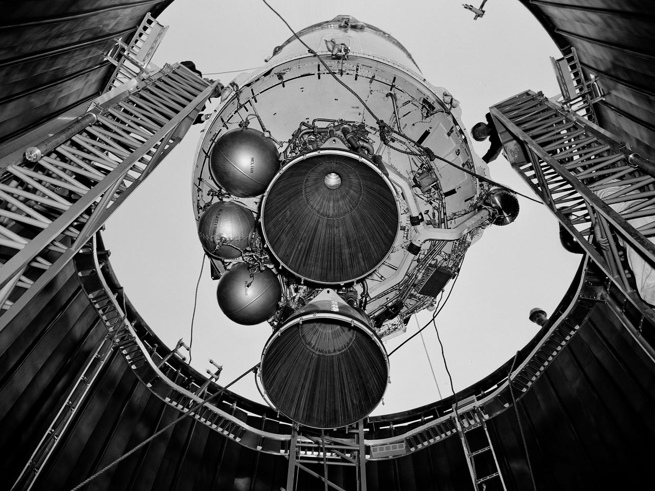
A Centaur second-stage rocket is lowered into the vacuum tank inside the Space Power Chambers at NASA’s Lewis Research Center. Centaur was to be paired with an Atlas booster to send the Surveyor spacecraft to the moon as a precursor to the Apollo landings. Lewis was assigned responsibility for the Centaur Program after the failure of its first developmental flight in May 1962. Lewis’ Altitude Wind Tunnel was converted into two large test chambers—the Space Power Chambers. The facility’s vacuum chamber, seen here, allowed the Centaur to be stood up vertically and subjected to atmospheric conditions-- pressures, temperature, and radiation--similar to those it would encounter in space. The Centaur for these tests was delivered to Cleveland in a C‒130 aircraft on September 27, 1963. The rocket was set up in the facility’s high bay where Lewis technicians and General Dynamics consultants updated its flight systems to match the upcoming Atlas-Centaur‒4 mission. Months were spent reharnessing the Centaur’s electronics, learning about the systems, and being taught how to handle flight hardware. By early spring 1964, the extensive setup of both the spacecraft and the chamber was finally completed. On March 19 the Centaur was rolled out from the shop, hoisted high into the air by a crane, and lowered into the waiting space tank. Researchers were able to verify that the Centaur’s electronics and electrical systems functioned reliably in a space environment.
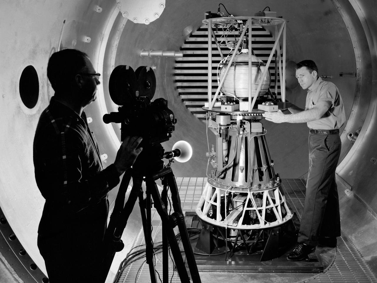
Mechanic Howard Wine inspects the setup of a spin isolator in Cell 2 of the Propulsion Systems Laboratory at the National Aeronautics and Space Administration (NASA) Lewis Research Center. Photographer Al Jecko filmed the proceedings. This test was unique in that the chamber’s altitude system was used, but not its inlet air flow. The test was in preparation for an upcoming launch of modified liquid hydrogen propellant tank on a sounding rocket. This Weightlessness Analysis Sounding Probe (WASP) was part of Lewis investigation into methods for controlling partially filled liquid hydrogen fuel tanks during flight. Second-stage rockets, the Centaur in particular, were designed to stop their engines and coast, then restart them when needed. During this coast period, the propellant often shifted inside the tank. This movement could throw the rocket off course or result in the sloshing of fuel away from the fuel pump. Wine was one of only three journeymen mechanics at Lewis when he was hired in January 1954. He spent his first decade in the Propulsion Systems Laboratory and was soon named a section head. Wine went on to serve as Assistant Division Chief and later served as an assistant to the director. Jecko joined the center in 1947 as a photographer and artist. He studied at the Cleveland School or Art and was known for his cartoon drawing. He worked at the center for 26 years.
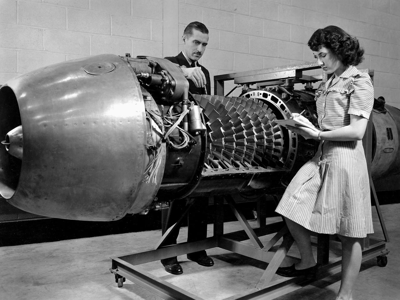
Researcher Robert Miller led an investigation into the combustor performance of a German Jumo 004 engine at the National Advisory Committee for Aeronautics (NACA) Lewis Flight Propulsion Laboratory. The Jumo 004 powered the world's first operational jet fighter, the Messerschmitt Me 262, beginning in 1942. The Me 262 was the only jet aircraft used in combat during World War II. The eight-stage axial-flow compressor Jumo 004 produced 2000 pounds of thrust. The US Army Air Forces provided the NACA with a Jumo 004 engine in 1945 to study the compressor’s design and performance. Conveniently the engine’s designer Anselm Franz had recently arrived at Wright-Patterson Air Force Base in nearby Dayton, Ohio as part of Project Paperclip. The Lewis researchers used a test rig in the Engine Research Building to analyze one of the six combustion chambers. It was difficult to isolate a single combustor’s performance when testing an entire engine. The combustion efficiency, outlet-temperature distribution, and total pressure drop were measured. The researchers determined the Jumo 004’s maximum performance was 5000 revolutions per minute at a 27,000 foot altitude and 11,000 revolutions per minute at a 45,000 foot altitude. The setup in this photograph was created for a tour of NACA Lewis by members of the Institute of Aeronautical Science on March 22, 1945.
A researcher at the National Advisory Committee for Aeronautics (NACA) Lewis Flight Propulsion Laboratory checks the setup of a RJM-2 ramjet model in the test section of the 8- by 6-Foot Supersonic Wind Tunnel. The 8- by 6 was not only the laboratory’s first large supersonic wind tunnel, but it was also the NACA’s first facility capable of testing an operating engine at supersonic speeds. The 8- by 6-foot tunnel has been used to study engine inlets, fuel injectors, flameholders, exit nozzles, and controls on ramjet and turbojet propulsion systems. The 8-foot wide and 6-foot tall test section consisted of 1-inch thick steel plates with hatches on the floor and ceiling to facilitate the installation of the test article. The two windows seen on the right wall allowed photographic equipment to be set up. The test section was modified in 1956 to accommodate transonic research. NACA engineers drilled 4,700 holes into the test section walls to reduce transonic pressure disturbances and shock waves. NACA Lewis undertook an extensive research program on ramjets in the 1940s using several of its facilities. Ramjets provide a very simple source of propulsion. They are basically a tube which ingests high speed air, ignites it, and then expels the heated air at a significantly higher velocity. Ramjets are extremely efficient and powerful but can only operate at high speeds. Therefore, they require a booster rocket or aircraft drop to accelerate them to high speeds before they can operate.
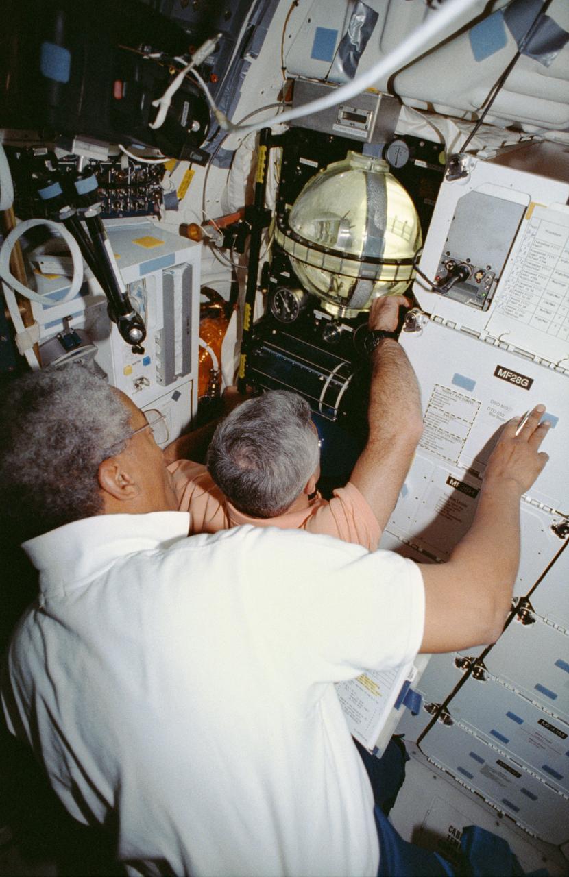
STS053-04-018 (2-9 Dec 1992) --- Astronauts Guion S. Bluford (left) and Michael R. U. (Rich) Clifford monitor the Fluid Acquisition and Resupply Equipment (FARE) onboard the Space Shuttle Discovery. Clearly visible in the mid-deck FARE setup is one of two 12.5-inch spherical tanks made of transparent acrylic, one to supply and one to receive fluids. The purpose of FARE is to investigate the dynamics of fluid transfer in microgravity and develop methods for transferring vapor-free propellants and other liquids that must be replenished in long-term space systems like satellites, Extended-Duration Orbiters (EDO), and Space Station Freedom. Eight times over an eight-hour test period, the mission specialists conducted the FARE experiment. A sequence of manual valve operations caused pressurized air from the bottles to force fluids from the supply tank to the receiver tank and back again to the supply tank. Baffles in the receiver tank controlled fluid motion during transfer, a fine-mesh screen filtered vapor from the fluid, and the overboard vent removed vapor from the receiver tank as the liquid rose. FARE is managed by NASA's Marshall Space Flight Center (MSFC) in Alabama. The basic equipment was developed by Martin Marietta for the Storable Fluid Management Demonstration. Susan L. Driscoll is the principal investigator.
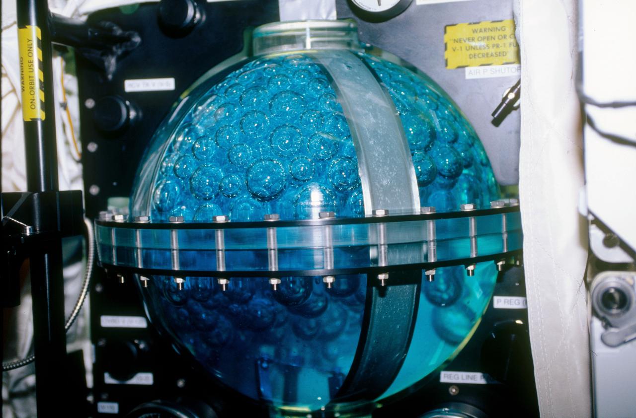
STS053-09-019 (2 - 9 Dec 1992) --- A medium close-up view of part of the Fluid Acquisition and Resupply Equipment (FARE) onboard the Space Shuttle Discovery. Featured in the mid-deck FARE setup is fluid activity in one of two 12.5-inch spherical tanks made of transparent acrylic. Pictured is the receiver tank. The other tank, out of frame below, is for supplying fluids. The purpose of FARE is to investigate the dynamics of fluid transfer in microgravity and develop methods for transferring vapor-free propellants and other liquids that must be replenished in long-term space systems like satellites, Extended-Duration Orbiters (EDO), and Space Station Freedom. Eight times over an eight-hour test period, the mission specialists conducted the FARE experiment. A sequence of manual valve operations caused pressurized air from the bottles to force fluids from the supply tank to the receiver tank and back again to the supply tank. Baffles in the receiver tank controlled fluid motion during transfer, a fine-mesh screen filtered vapor from the fluid, and the overboard vent removed vapor from the receiver tank as the liquid rose. FARE is managed by NASA's Marshall Space Flight Center (MSFC) in Alabama. The basic equipment was developed by Martin Marietta for the Storable Fluid Management Demonstration. Susan L. Driscoll is the principal investigator.
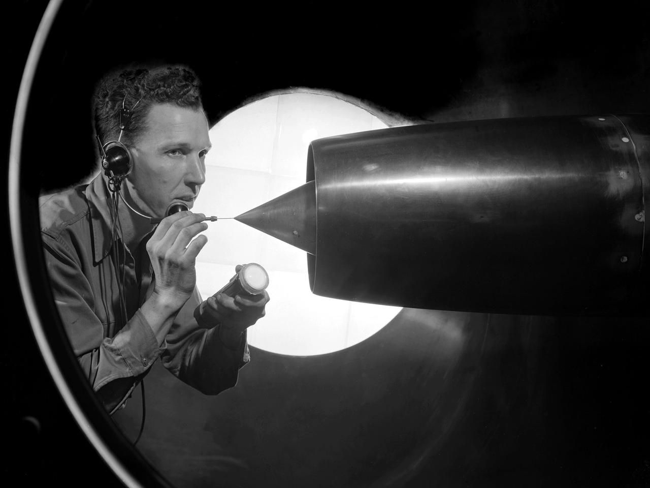
William Kerslake, a combustion researcher at the National Advisory Committee for Aeronautics (NACA) Lewis Flight Propulsion Laboratory, examines the setup of a transparent rocket in a Rocket Laboratory test cell. Kerslake joined NACA Lewis the previous summer after graduating from the Case Institute of Technology with a chemistry degree. His earliest professional research concentrated on combustion instability in small rocket engines. While at Case the quiet, 250-pound Kerslake also demonstrated his athletic prowess on the wrestling team. He continued wrestling for roughly a decade afterwards while conducting his research with the NACA. Kerslake participated in Olympic competitions in Helsinki (1952), Melbourne (1956), and Rome (1960). He won 30 national championships in three different weight classes and captured the gold at the 1955 Pan American Games in Mexico City. Kerslake accomplished all this while maintaining his research career, raising a family, and paying his own expenses. As his wrestling career was winding down in the early 1960s, Kerslake’s professional career changed, as well. He was transferred to Harold Kaufman’s Electrostatic Propulsion Systems Section in the new Electromagnetic Propulsion Division. Kaufman was developing the first successful ion engine at the time, and Kerslake spent the remainder of his career working in the electric propulsion field. He was heavily involved in the two Space Electric Rocket Test (SERT) missions which demonstrated that the ion thrusters could successfully operate in space. Kerslake retired in 1985 with over 30 years of service.
![Astronaut Neil Armstrong examines a Vertical and Short Takeoff and Landing test setup in the 9- by 15-Foot Low Speed Wind Tunnel at the National Aeronautics and Space Administration (NASA) Lewis Research Center. Armstrong spent February 6, 1970 at Lewis attending technical meetings and touring some facilities. Just six months after Armstrong had returned from the moon looming agency budget cuts were already a concern in his comments. He noted that NASA had to “find a balanced approach…and [make] aggressive use of available facilities.” Armstrong spent four months at the center as a research pilot in 1955. Armstrong had served as a Navy pilot during the Korean War then earned a degree in aeronautical engineering at Purdue University. He was recruited by Lewis while at Purdue and began at the center shortly after graduation. During his brief tenure in Cleveland Armstrong served as both a test pilot and research engineer, primarily involved with icing research. In his role as research pilot Armstrong also flew a North American F-82 Twin Mustang over the ocean near Wallops Island to launch small instrumented rockets from high altitudes down into the atmosphere to obtain high Mach numbers. After four months in Cleveland a position opened up at what is today the Dryden Flight Research Center. Armstrong’s career in Cleveland officially ended on June 30, 1955.](https://images-assets.nasa.gov/image/GRC-1970-C-00473/GRC-1970-C-00473~medium.jpg)
Astronaut Neil Armstrong examines a Vertical and Short Takeoff and Landing test setup in the 9- by 15-Foot Low Speed Wind Tunnel at the National Aeronautics and Space Administration (NASA) Lewis Research Center. Armstrong spent February 6, 1970 at Lewis attending technical meetings and touring some facilities. Just six months after Armstrong had returned from the moon looming agency budget cuts were already a concern in his comments. He noted that NASA had to “find a balanced approach…and [make] aggressive use of available facilities.” Armstrong spent four months at the center as a research pilot in 1955. Armstrong had served as a Navy pilot during the Korean War then earned a degree in aeronautical engineering at Purdue University. He was recruited by Lewis while at Purdue and began at the center shortly after graduation. During his brief tenure in Cleveland Armstrong served as both a test pilot and research engineer, primarily involved with icing research. In his role as research pilot Armstrong also flew a North American F-82 Twin Mustang over the ocean near Wallops Island to launch small instrumented rockets from high altitudes down into the atmosphere to obtain high Mach numbers. After four months in Cleveland a position opened up at what is today the Dryden Flight Research Center. Armstrong’s career in Cleveland officially ended on June 30, 1955.
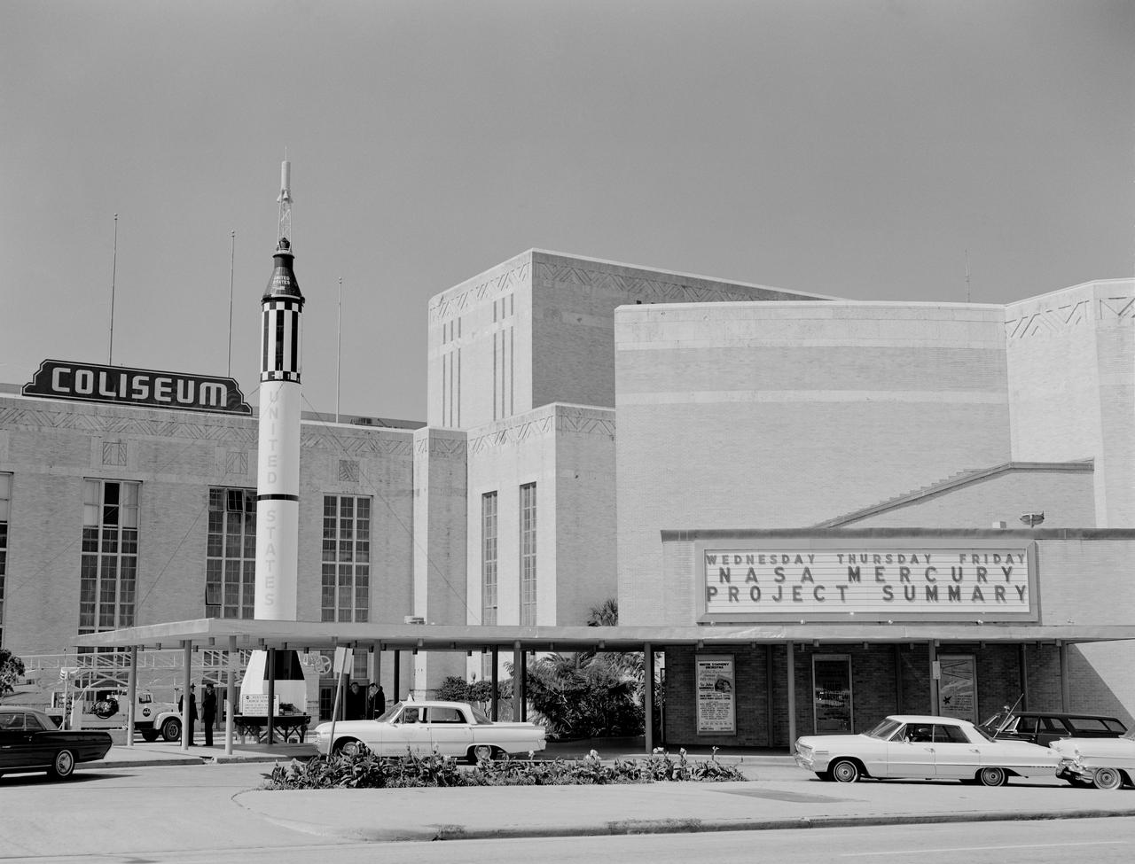
In October 1963, the Project Mercury Summary Conference was held in the Houston, TX, Coliseum. This series of 44 photos is documentation of that conference. A view of the Houston, TX, Coliseum, and parking area in front with a Mercury Redstone Rocket setup in the parking lot for display (S63-16451). A view of an Air Force Atlas Rocket, a Mercury Redstone Rocket, and a Mercury Spacecraft on a test booster on display in the front area of the Coliseum (S63-16452). A view an Air Force Atlas Rocket and a Mercury Redstone Rocket set up for display with the Houston City Hall in the background (S63- 16453). This view shows the Atlas Rocket, Mercury Redstone, and Mercury Test Rocket with the Houston, TX, Coliseum in the background (S63- 16454). A balcony view, from the audience right side, of the attendees looking at the stage (S63-16455). A view of the NASA Space Science Demonstration with equipment setup on a table, center stage and Space Science Specialist briefing the group as he pours Liquid Oxygen into a beaker (S63-16456). View of the audience from the balcony on the audience right showing the speakers lecturn on stage to the audience left (S63-16457). A view of attendees in the lobby. Bennet James, MSC Public Affairs Office is seen to the left of center (S63-16458). Another view of the attendees in the lobby (S63- 16459). In this view, Astronaut Neil Armstrong is seen writing as others look on (S63-16460). In this view of the attendees, Astronauts Buzz Aldrin and Walt Cunningham are seen in the center of the shot. The October Calendar of Events is visable in the background (S63-16461). Dr. Charles Berry is seen in this view to the right of center, seated in the audience (S63-16462). View of " Special Registration " and the five ladies working there (S63-16463). A view from behind the special registration table, of the attendees being registered (S63-16464). A view of a conference table with a panel seated. (R-L): Dr. Robert R. Gilruth, Hugh L. Dryden, Walter C. Williams, and an unidentified man (S63- 16465). A closeup of the panel at the table with Dr. Gilruth on the left (S63-16466). About the same shot as number S63-16462, Dr. Berry is seen in this shot as well (S63-16467). In this view the audio setup is seen. In the audience, (L-R): C. C. Kraft, Vernon E. (Buddy) Powell, Public Affairs Office (PAO); and, in the foreground mixing the audio is Art Tantillo; and, at the recorder is Doyle Hodges both of the audio people are contractors that work for PAO at MSC (S63-16468). In this view Maxime Faget is seen speaking at the lecturn (S63-16469). Unidentified person at the lecturn (S63-16470). In this view the motion picture cameras and personel are shown documenting the conference (S63-16471). A motion picture cameraman in the balcony is shown filming the audience during a break (S63- 16472). Family members enjoy an exhibit (S63-16473). A young person gets a boost to look in a Gemini Capsule on display (S63-16474). A young person looks at the Gemini Capsule on display (S63-16475). Dr. Robert R. Gilruth is seen at the conference table (S63-16476). Walt Williams is seen in this view at the conference table (S63-16477). Unidentified man sitting next to Walt Williams (S63-16478). (L-R): Seated at the conference table, Dr. Robert Gilruth, Hugh L. Dryden, and Walt Williams (S63- 16479). Group in lobby faces visable, (L-R): Walt Williams, unidentified person, Dr. Robert Gilruth, Congressman (S63-16480). Man in uniform at the lecturn (S63-16481). Astronaut Leroy Gordon Cooper at the lecturn (S63-16482). Astronaut Cooper at the lecturn with a picture on the screen with the title, " Astronaut Names for Spacecraft " (S63-16483). Dr. Gilruth at the lecturn (S63-16484). Walt Williams at the lecturn (S63-16485). Unidentified man at the lecturn (S63-16486). John H. Boynton addresses the Summary Conference (S63-16487). (L-R): Astronaut Leroy Gordon Cooper, Mrs. Cooper, Senator Cris Cole, and Mrs. Cole (S63- 16488). In this view in the lobby, Senator and Mrs. Cris Cole, with Astronaut Gordon Cooper standing near the heatshield, and Mrs. Cooper; next, on the right is a press photographer (S63-16489). (L-R): Astronaut L. Gordon Cooper and Mrs. Cooper, unidentified man, and Senator Walter Richter (S63-16490). (L-R): Eugene Horton, partially obscured, briefs a group on the Mercury Spacecraft, an unidentified person, Harold Ogden, a female senator, Senator Chris Cole, Mrs. Cole, an unidentified female, Senator Walter Richter, Jim Bower, and an unidentified female (S63-16491). In this view, Mrs. Jim Bates is seen in the center, and Senator Walter Richter to the right (S63- 16492). The next three (3) shots are 4X5 CN (S63-16493 - S63-16495). In this view a NASA Space Science Demonstration is seen (S63-16493). In this view a shot of the conference table is seen, and, (L-R): Dr. Robert R. Gilruth, Hugh L. Dryden, Mr. Walter Williams, and an unidentfied man (S63-16494 - S63-16495). HOUSTON, TX
Engineer Emmanuel Decrossas of NASA's Jet Propulsion Laboratory in Southern California makes an adjustment to an antenna's connector, part of a NASA telecommunications payload called User Terminal, at Firefly Aerospace's facility in Cedar Park, Texas, in August 2025. Figure A (https://photojournal.jpl.nasa.gov/figures/PIA26596_figA.jpg) shows members of the team from JPL and NASA (dark blue) and Firefly (white) with the User Terminal antenna, radio, and other components on the bench behind them. Managed by JPL, the User Terminal will test a new, low-cost lunar communications system that future missions to the Moon's far side could use to transfer data to and from Earth via lunar relay satellite. The User Terminal payload will be installed atop Firefly's Blue Ghost Mission 2 lunar lander, which is slated to launch to the Moon's far side in 2026 under NASA's CLPS (Commercial Lunar Payload Services) initiative. NASA's Apollo missions brought large and powerful telecommunications systems to the lunar near-side surface to communicate directly with Earth. But spacecraft on the far side will not have that option because only the near side of the Moon is visible to Earth. Sending messages between the Moon and Earth via a relay orbiter enables communication with the lunar far side and improves it at the Moon's poles. The User Terminal will for the first time test such a setup for NASA by using a compact, lightweight software defined radio, antenna, and related hardware to communicate with a satellite that Blue Ghost Mission 2 is delivering to lunar orbit: ESA's (the European Space Agency's) Lunar Pathfinder. The User Terminal radio and antenna installed on the Blue Ghost lander will be used to commission Lunar Pathfinder, sending test data back and forth. After the lander ceases operations as planned at the end of a single lunar day (about 14 Earth days), a separate User Terminal radio and antenna installed on LuSEE-Night – another payload on the lander – will send LuSEE-Night's data to Lunar Pathfinder, which will relay the information to a commercial network of ground stations on Earth. LuSEE-Night is a radio telescope that expected to operate for at least 1½ years; it is a joint effort by NASA, the U.S. Department of Energy, and University of California, Berkeley's Space Sciences Laboratory. Additionally, User Terminal will be able to communicate with another satellite that's being delivered to lunar orbit by Blue Ghost Mission 2: Firefly's own Elytra Dark orbital vehicle. The hardware on the lander is only part of the User Terminal project, which was also designed to implement a new S-band two-way protocol, or standard, for short-range space communications between entities on the lunar surface (such as rovers and landers) and lunar orbiters, enabling reliable data transfer between them. The standard is a new version of a space communications protocol called Proximity-1 that was initially developed more than two decades ago for use at Mars by an international standard body called the Consultative Committee for Space Data Systems (CCSDS), of which NASA is a member agency. The User Terminal team made recommendations to CCSDS on the development of the new lunar S-band standard, which was specified in 2024. The new standard will enable lunar orbiters and surface spacecraft from various entities – NASA and other civil space agencies as well as industry and academia – to communicate with each other, a concept known as interoperability. At Mars, NASA rovers communicate with various Red Planet orbiters using the Ultra-High Frequency (UHF) radio band version of the Proximity-1 standard. On the Moon's far side, use of UHF is reserved for radio astronomy science; so a new lunar standard was needed using a different frequency range, S-band, as were more efficient modulation and coding schemes to better fit the available frequency spectrum specified by the new standard. User Terminal is funded by NASA's Exploration Science Strategy and Integration Office, part of the agency's Science Mission Directorate, which manages the CLPS initiative. JPL manages the project and supported development of the new S-band radio standard and the payload in coordination with Vulcan Wireless in Carlsbad, California, which built the radio. Caltech in Pasadena manages JPL for NASA. https://photojournal.jpl.nasa.gov/catalog/PIA26596
NASA Glenn Research Center has received the first of three Advanced Electric Propulsion System (AEPS) thrusters for the Gateway lunar space station. Built by L3Harris Technologies, the thruster will undergo testing before integration with Gateway’s Power and Propulsion Element, launching with the HALO module ahead of Artemis IV.