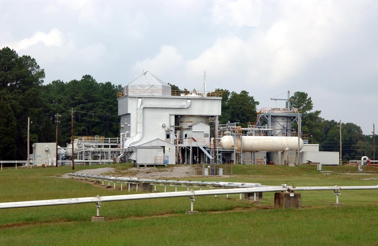
This is a ground level view of Test Stand 300 at the east test area of the Marshall Space Flight Center. Test Stand 300 was constructed in 1964 as a gas generator and heat exchanger test facility to support the Saturn/Apollo Program. Deep-space simulation was provided by a 1960 modification that added a 20-ft thermal vacuum chamber and a 1981 modification that added a 12-ft vacuum chamber. The facility was again modified in 1989 when 3-ft and 15-ft diameter chambers were added to support Space Station and technology programs. This multiposition test stand is used to test a wide range of rocket engine components, systems, and subsystems. It has the capability to simulate launch thermal and pressure profiles. Test Stand 300 was designed for testing solid rocket booster (SRB) insulation panels and components, super-insulated tanks, external tank (ET) insulation panels and components, Space Shuttle components, solid rocket motor materials, and advanced solid rocket motor materials.
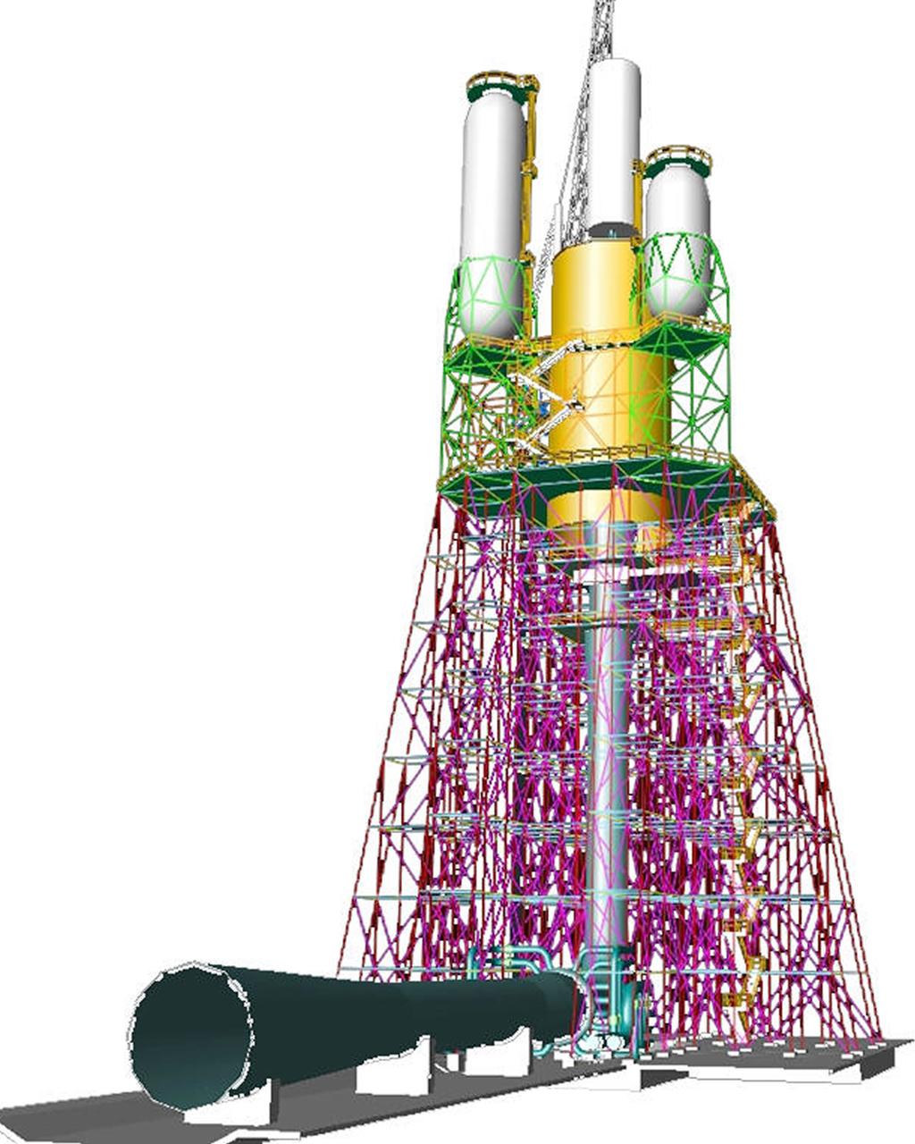
This engineer's concept drawing of the A-3 Test Stand shows the 300-foot-tall structure's open steel frame and large exhaust diffuser.
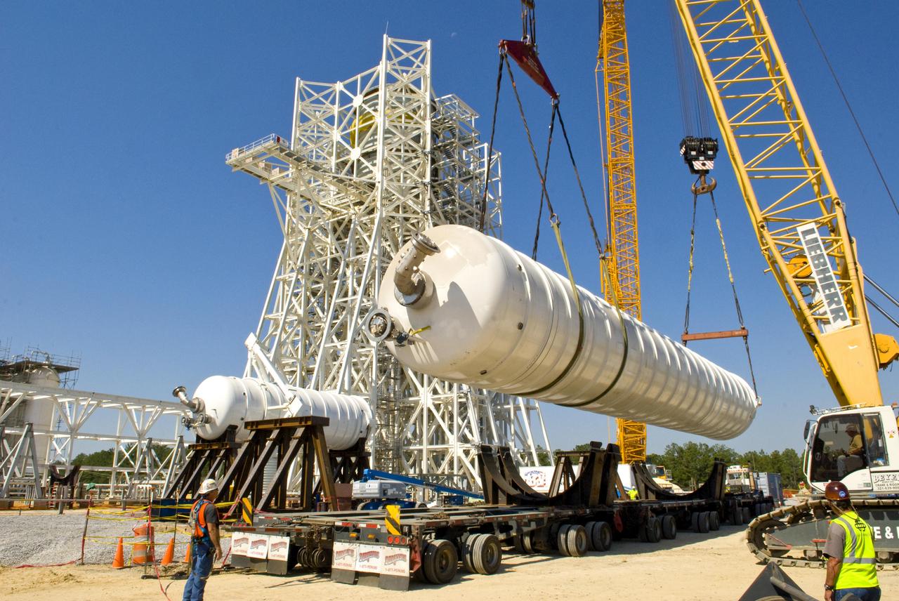
An 80,000-gallon liquid hydrogen tank is placed at the A-3 Test Stand construction site on Sept. 24, 2010. The tank will provide propellant for tests of next-generation rocket engines at the stand. It will be placed upright on top of the stand, helping to increase the overall height to 300 feet. Once completed, the A-3 Test Stand will enable operators to test rocket engines at simulated altitudes of up to 100,000 feet. The A-3 stand is the first large rocket engine test structure to be built at Stennis Space Center since the 1960s.
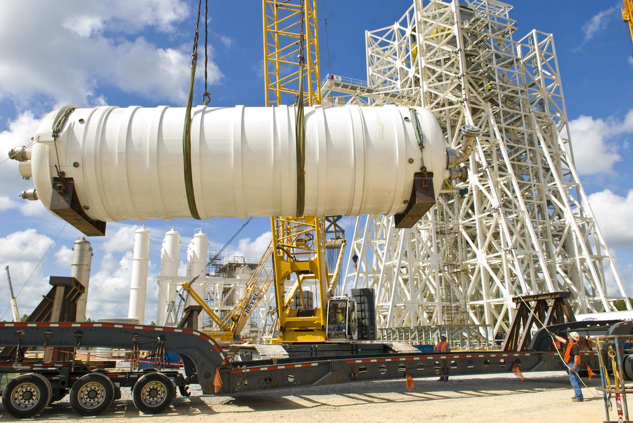
A 35,000-gallon liquid oxygen tank is placed at the A-3 Test Stand construction site on Sept. 24, 2010. The tank will provide propellant for tests of next-generation rocket engines at the stand. It will be placed upright on top of the stand, helping to increase the overall height to 300 feet. Once completed, the A-3 Test Stand will enable operators to test rocket engines at simulated altitudes of up to 100,000 feet. The A-3 stand is the first large rocket engine test structure to be built at Stennis Space Center since the 1960s.
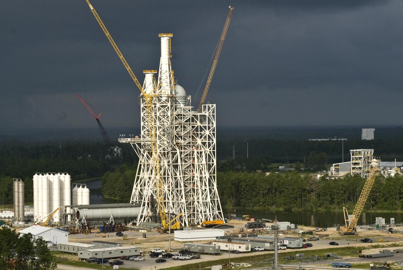
Stennis Space Center employees have installed liquid oxygen and liquid hydrogen tanks atop the A-3 Test Stand, raising the structure to its full 300-foot height. The stand is being built to test next-generation rocket engines that could carry humans beyond low-Earth orbit into deep space. The A-3 Test Stand is scheduled for completion and activation in 2013.
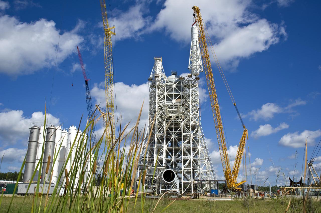
Stennis Space Center employees marked another construction milestone July 25 with installation of the 85,000-gallon liquid hydrogen tank atop the A-3 Test Stand. The 300-foot-tall stand is being built to test next-generation rocket engines that could carry humans into deep space once more. The liquid hydrogen tank and a 35,000-gallon liquid oxygen tank installed atop the steel structure earlier in June will provide fuel propellants for testing the engines.

Stennis Space Center firefighter Rodney Boone rappels a tower structure during an onsite training exercise May 11, 2012. The training focused on high-angle rope rescues, which could be needed on the new 300-foot-tall A-3 Test Stand at Stennis.
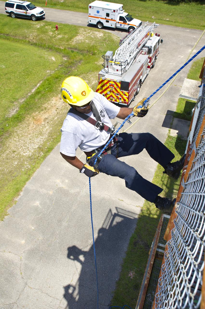
Stennis Space Center firefighter Rodney Boone rappels a tower structure during an onsite training exercise May 11, 2012. The training focused on high-angle rope rescues, which could be needed on the new 300-foot-tall A-3 Test Stand at Stennis.
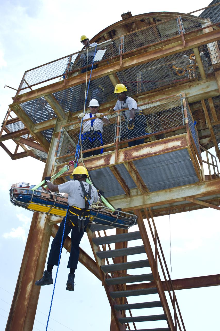
Instructor Rob Mortin watches as Stennis Space Center firefighters Lt. Greg Lampley, Rodney Boone, Vance Forrest and Billy Scarborough practice high-angle rope rescue techniques during a May 11, 2012, training exercise. The exercise specifically focused on scenarios applicable to the 300-foot-tall, open-steel-structure A-3 Test Stand under construction at the rocket engine test facility.

Instructor Rob Mortin watches as Stennis Space Center firefighters Lt. Greg Lampley, Rodney Boone, Vance Forrest and Billy Scarborough practice high-angle rope rescue techniques during a May 11, 2012, training exercise. The exercise specifically focused on scenarios applicable to the 300-foot-tall, open-steel-structure A-3 Test Stand under construction at the rocket engine test facility.
Tree clearing for the site of the new A-3 Test Stand at Stennis Space center began June 13. NASA's first new large rocket engine test stand to be built since the site's inception, A-3 construction begins a historic era for America's largest rocket engine test complex. The 300-foot-tall structure is scheduled for completion in August 2010. A-3 will perform altitude tests on the Constellation's J-2X engine that will power the upper stage of the Ares I crew launch vehicle and earth departure stage of the Ares V cargo launch vehicle. The Constellation Program, NASA's plan for carrying out the nation's Vision for Space Exploration, will return humans to the moon and eventually carry them to Mars and beyond.
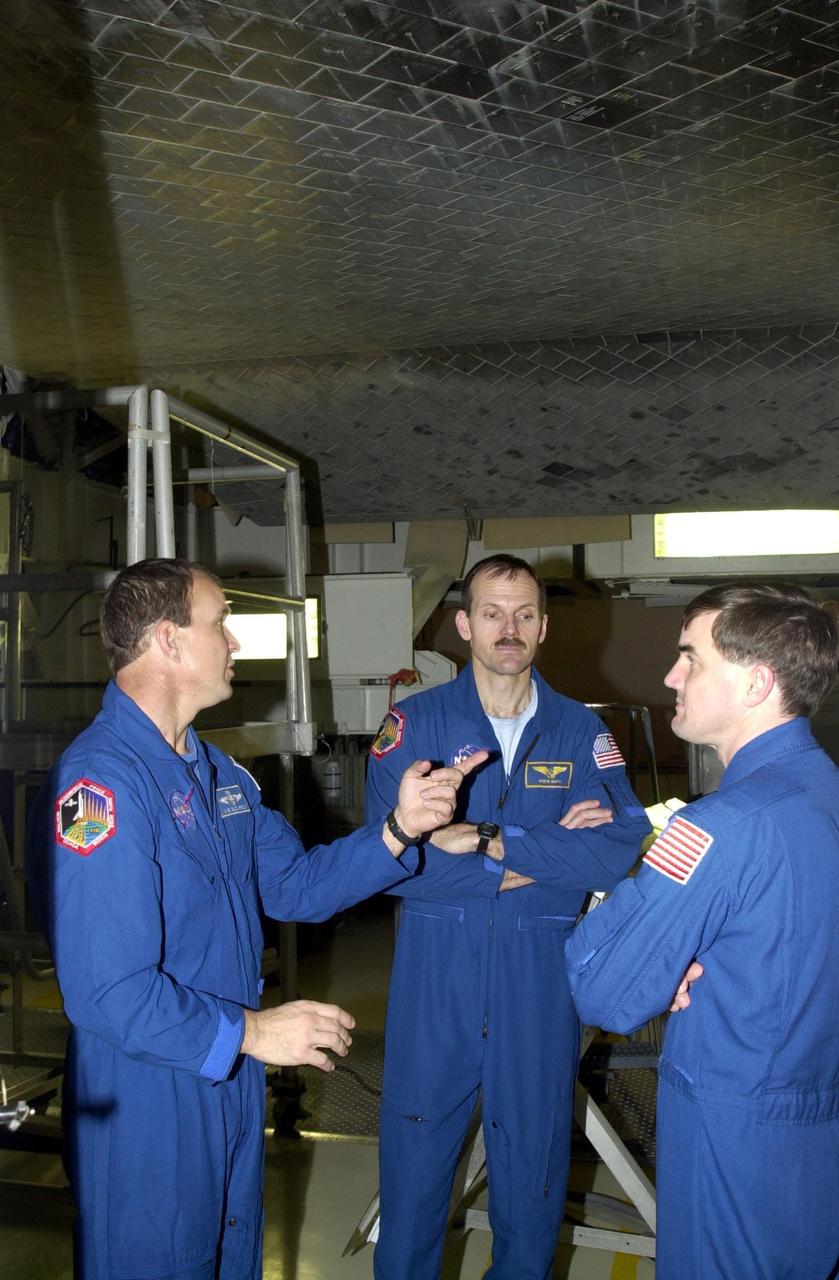
KENNEDY SPACE CENTER, FLA. -- Standing underneath the orbiter Atlantis in the Orbiter Processing Facility are STS-110 Commander Michael Bloomfield and Mission Specialists Steven Smith and Rex Walheim. They and other crew members are taking part in Crew Equipment Integration Test activities, which include familiarization with the vehicle and payload. The mission, 13th assembly flight to the International Space Station, includes the Integrated Truss Structure S0. The ITS S0 is the center segment on the Space Station, part of the 300-foot (91-meter) truss attached to the U.S. Lab. By assembly completion, four more truss segments will attach to either side of the S0 truss. STS-110 is scheduled to launch April 4, 2002
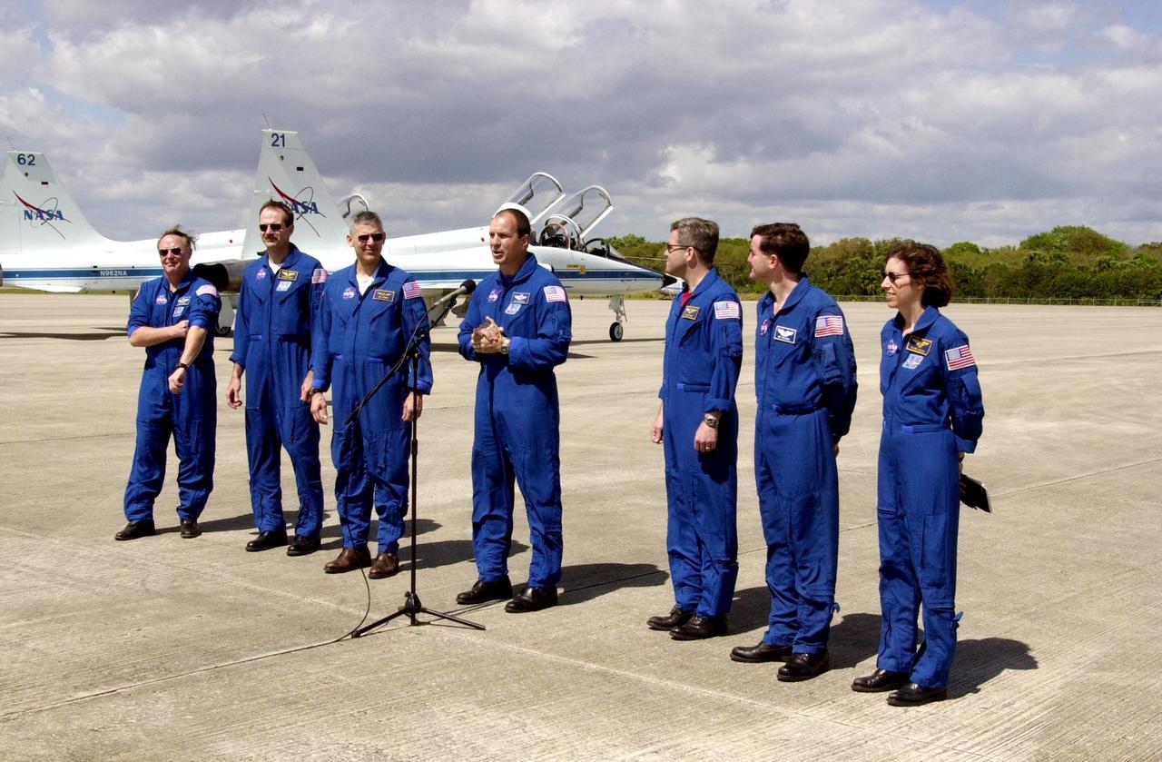
KENNEDY SPACE CENTER, FLA. -- Prior to their departure, the STS-110 crew pauses for the media at the Shuttle Landing Facility. Standing left to right are Mission Specialists Jerry Ross, Steven Smith and Lee Morin; Commander Michael Bloomfield; Pilot Stephen Frick; and Mission Specialists Rex Walheim and Ellen Ochoa. The crew was at KSC for Terminal Countdown Demonstration Test activities that included the payload familiarization and a simulated launch countdown. Scheduled for launch April 4, the 11-day STS-110 mission will feature Space Shuttle Atlantis docking with the International Space Station (ISS) and delivering the S0 truss, the centerpiece-segment of the primary truss structure that will eventually extend over 300 feet
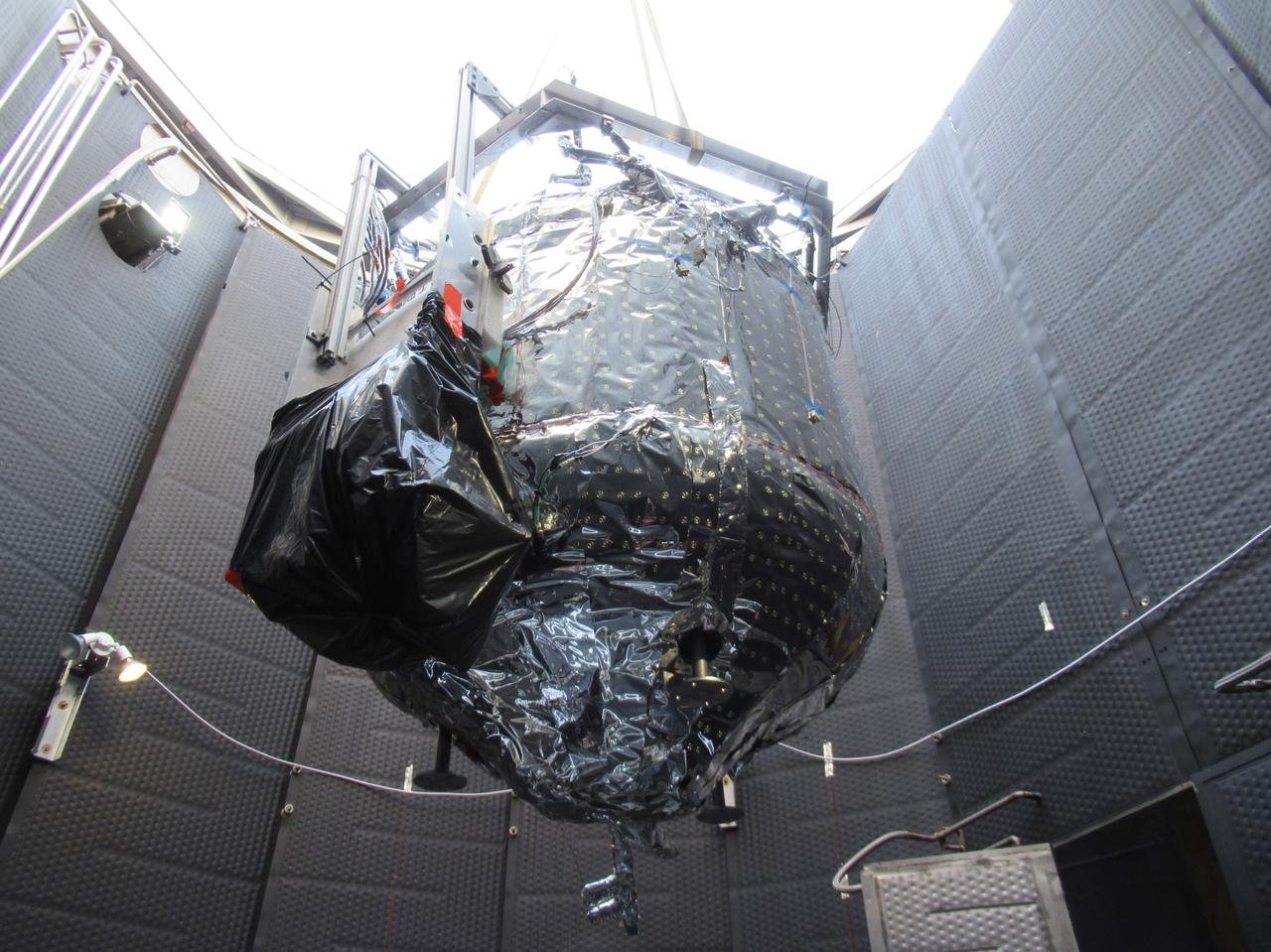
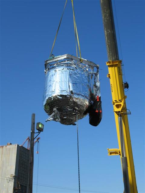
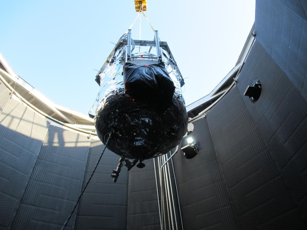
These photos show how teams at NASA’s Marshall Space Flight Center in Huntsville, Alabama, are testing an innovative approach to achieve zero boiloff storage of liquid hydrogen using two stages of active cooling, which could prevent the loss of valuable propellant during future long-duration spaceflight missions. Test teams installed the propellant tank in Test Stand 300 at NASA Marshall in early June, and the 90-day test campaign is scheduled to conclude in September. The tank is wrapped in a multi-layer insulation blanket that includes a thin aluminum heat shield fitted between layers. A second set of tubes, carrying helium at about minus 298 Fahrenheit, is integrated into the shield. This intermediate cooling layer intercepts and rejects incoming heat before it reaching the tank, easing the heat load on the tube-on-tank system. The Cryogenic Fluid Management Portfolio Project is a cross-agency team based at NASA Marshall and the agency’s Glenn Research Center in Cleveland. The cryogenic portfolio’s work is under NASA’s Technology Demonstration Missions Program, part of NASA’s Space Technology Mission Directorate, and is comprised of more than 20 individual technology development activities. For more information, contact NASA Marshall’s Office of Communications at 256-544-0034.

These photos show how teams at NASA’s Marshall Space Flight Center in Huntsville, Alabama, are testing an innovative approach to achieve zero boiloff storage of liquid hydrogen using two stages of active cooling, which could prevent the loss of valuable propellant during future long-duration spaceflight missions. Test teams installed the propellant tank in Test Stand 300 at NASA Marshall in early June, and the 90-day test campaign is scheduled to conclude in September. The tank is wrapped in a multi-layer insulation blanket that includes a thin aluminum heat shield fitted between layers. A second set of tubes, carrying helium at about minus 298 Fahrenheit, is integrated into the shield. This intermediate cooling layer intercepts and rejects incoming heat before it reaching the tank, easing the heat load on the tube-on-tank system. The Cryogenic Fluid Management Portfolio Project is a cross-agency team based at NASA Marshall and the agency’s Glenn Research Center in Cleveland. The cryogenic portfolio’s work is under NASA’s Technology Demonstration Missions Program, part of NASA’s Space Technology Mission Directorate, and is comprised of more than 20 individual technology development activities. For more information, contact NASA Marshall’s Office of Communications at 256-544-0034.
These photos show how teams at NASA’s Marshall Space Flight Center in Huntsville, Alabama, are testing an innovative approach to achieve zero boiloff storage of liquid hydrogen using two stages of active cooling, which could prevent the loss of valuable propellant during future long-duration spaceflight missions. Test teams installed the propellant tank in Test Stand 300 at NASA Marshall in early June, and the 90-day test campaign is scheduled to conclude in September. The tank is wrapped in a multi-layer insulation blanket that includes a thin aluminum heat shield fitted between layers. A second set of tubes, carrying helium at about minus 298 Fahrenheit, is integrated into the shield. This intermediate cooling layer intercepts and rejects incoming heat before it reaching the tank, easing the heat load on the tube-on-tank system. The Cryogenic Fluid Management Portfolio Project is a cross-agency team based at NASA Marshall and the agency’s Glenn Research Center in Cleveland. The cryogenic portfolio’s work is under NASA’s Technology Demonstration Missions Program, part of NASA’s Space Technology Mission Directorate, and is comprised of more than 20 individual technology development activities. For more information, contact NASA Marshall’s Office of Communications at 256-544-0034.
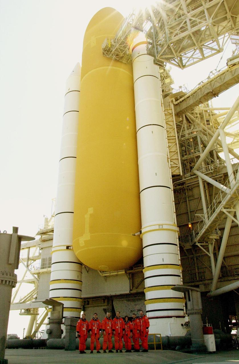
KENNEDY SPACE CENTER, FLA. -- Dwarfed by the external tank and solid rocket boosters of Space Shuttle Atlantis is the STS-110 crew. Standing left to right are Mission Specialists Jerry Ross, Rex Walheim and Lee Morin; Commander Michael Bloomfield; Mission Specialist Ellen Ochoa; Pilot Stephen Frick; and Mission Specialist Steven Smith. The crew is taking a break during Terminal Countdown Demonstration Test activities to pose for the photo. The TCDT, which includes emergency egress training and a simulated launch countdown, is held at KSC prior to each Space Shuttle flight. Scheduled for launch April 4, the 11-day mission will feature Shuttle Atlantis docking with the International Space Station (ISS) and delivering the S0 truss, the centerpiece-segment of the primary truss structure that will eventually extend over 300 feet
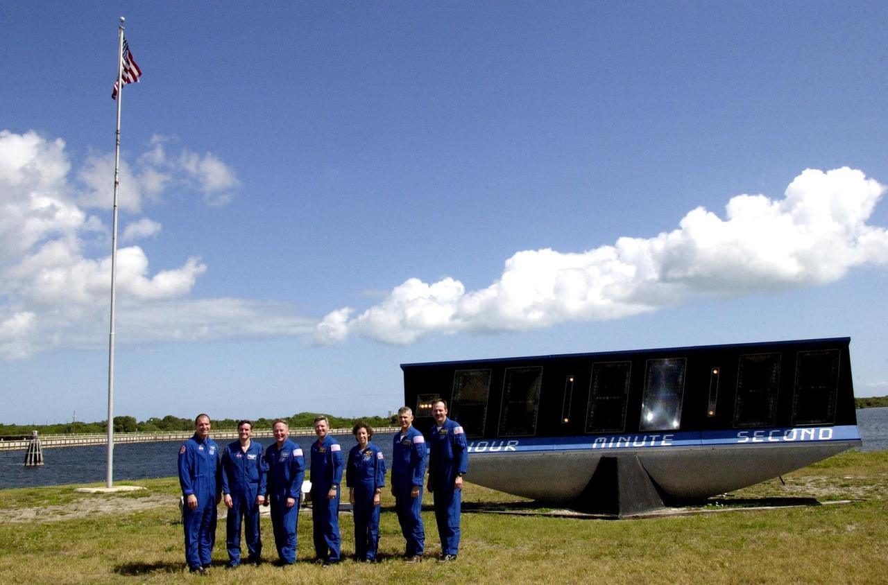
KENNEDY SPACE CENTER, FLA. -- Before departing for Houston, the STS-110 crew poses in front of the countdown clock that faces the grandstand at the Press Site. Standing left to right are Commander Michael Bloomfield, Mission Specialists Rex Walheim and Jerry Ross, Pilot Stephen Frick, and Mission Specialists Ellen Ochoa, Lee Morin and Steven Smith. The crew was at KSC for Terminal Countdown Demonstration Test activities that included payload familiarization and a simulated launch countdown. Scheduled for launch April 4, the 11-day STS-110 mission will feature Space Shuttle Atlantis docking with the International Space Station (ISS) and delivering the S0 truss, the centerpiece-segment of the primary truss structure that will eventually extend over 300 feet
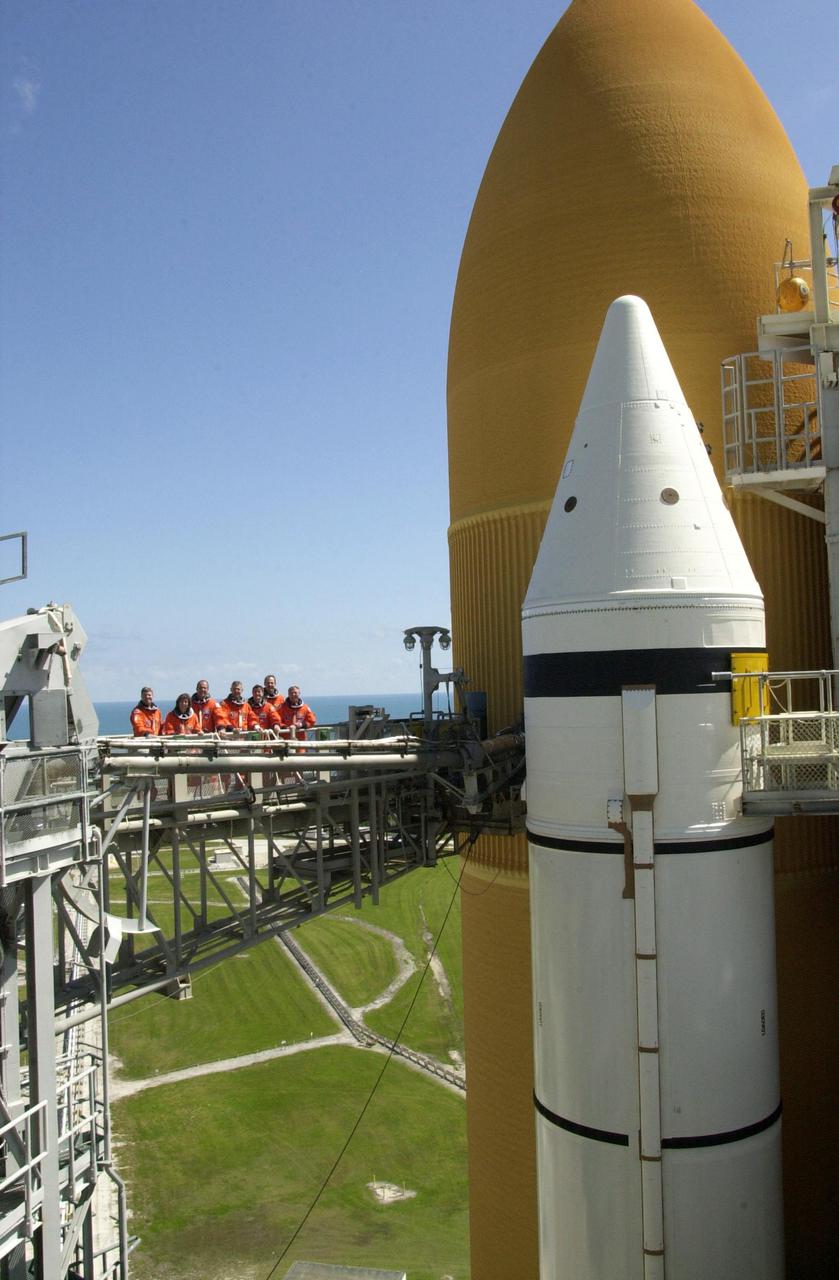
KENNEDY SPACE CENTER, FLA. -- The STS-110 crew takes a break on the launch pad during Terminal Countdown Demonstration Test activities to pose for a photo. Standing left to right are Pilot Stephen Frick, Mission Specialist Ellen Ochoa, Commander Michael Bloomfield, and Mission Specialists Lee Morin, Rex Walheim, Steven Smith and Jerry Ross. The TCDT, which includes emergency egress training and a simulated launch countdown, is held at KSC prior to each Space Shuttle flight. Scheduled for launch April 4, the 11-day mission will feature Shuttle Atlantis docking with the International Space Station (ISS) and delivering the S0 truss, the centerpiece-segment of the primary truss structure that will eventually extend over 300 feet

KENNEDY SPACE CENTER, Fla. -- In the Operations and Checkout Building, STS-110 crew members check out Integrated Truss Structure (ITS) S0, which will be part of the payload on the mission. On the left are Mission Specialists Jerry L. Ross and Rex J. Walheim. On the right, standing next to two trainers, is Mission Specialist Lee M. Morin. They and other crew members are taking part in a Crew Equipment Interface Test at KSC. Not shown are Commander Michael J. Bloomfield, Pilot Stephen N. Frick, and Mission Specialists Steven L. Smith and Ellen Ochoa. The ITS S0 is part of the payload on the mission. It is the center segment they will be installing on the International Space Station, part of the 300-foot (91-meter) truss attached to the U.S. Lab. By assembly completion, four more truss segments will attach to either side of the S0 truss. STS-110 is currently scheduled to launch in February 2002
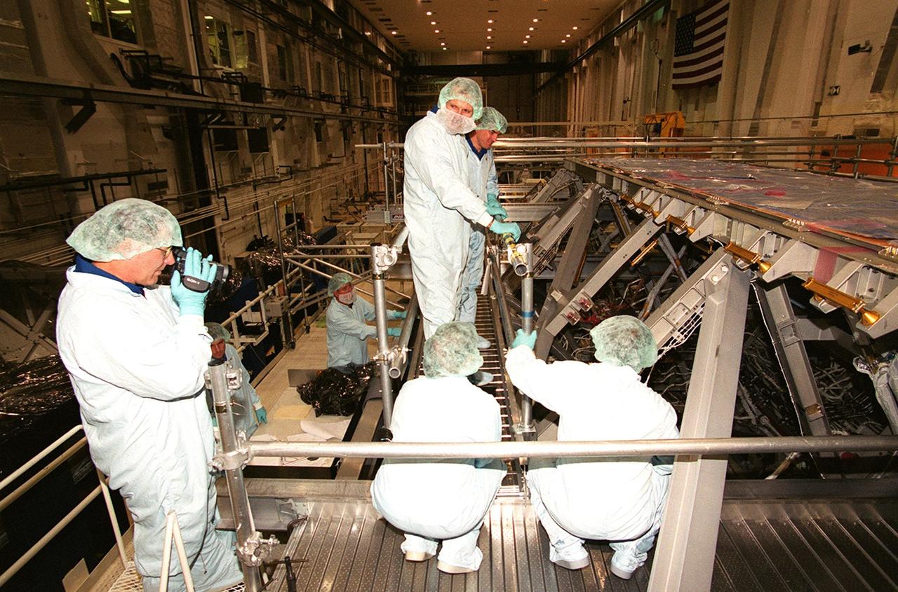
KENNEDY SPACE CENTER, Fla. -- In the Operations and Checkout Building, during a Crew Equipment Interface Test, members of the STS-110 crew check out Integrated Truss Structure (ITS) S0, which will be part of the payload on their mission. At left is Mission Specialist Jerry L. Ross, with a camera. Standing (center) are Mission Specialists Steven L. Smith and Rex J. Walheim. Other crew members (not shown) are Commander Michael J. Bloomfield, Pilot Stephen N. Frick, and Missin Specialists Ellen Ochoa and Lee M. Morin. The ITS S0 is part of the payload on the mission. It is the center segment they will be installing on the International Space Station, part of the 300-foot (91-meter) truss attached to the U.S. Lab. By assembly completion, four more truss segments will attach to either side of the S0 truss. STS-110 is currently scheduled to launch in February 2002

KENNEDY SPACE CENTER, FLA. -- With the external tank and solid rocket boosters of Space Shuttle Atlantis looming above them, the STS-110 crew takes a break during Terminal Countdown Demonstration Test activities to pose for a photo. . Standing left to right are Mission Specialists Jerry Ross, Rex Walheim and Lee Morin; Commander Michael Bloomfield; Mission Specialist Ellen Ochoa; Pilot Stephen Frick; and Mission Specialist Steven Smith. The TCDT, which includes emergency egress training and a simulated launch countdown, is held at KSC prior to each Space Shuttle flight. Scheduled for launch April 4, the 11-day mission will feature Shuttle Atlantis docking with the International Space Station (ISS) and delivering the S0 truss, the centerpiece-segment of the primary truss structure that will eventually extend over 300 feet
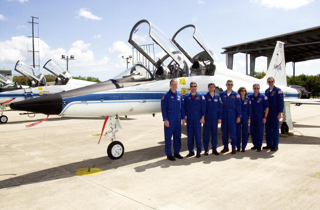
KENNEDY SPACE CENTER, FLA. -- The STS-110 crew poses in front of a T-38 jet aircraft at the Shuttle Landing Facility before departing for Houston. Standing left to right are Commander Michael Bloomfield, Pilot Stephen Frick and Mission Specialists Rex Walheim, Lee Morin, Ellen Ochoa, Jerry Ross and Steven Smith. The crew was at KSC for Terminal Countdown Demonstration Test activities that included payload familiarization and a simulated launch countdown. Scheduled for launch April 4, the 11-day STS-110 mission will feature Space Shuttle Atlantis docking with the International Space Station (ISS) and delivering the S0 truss, the centerpiece-segment of the primary truss structure that will eventually extend over 300 feet
These photos show how teams at NASA’s Marshall Space Flight Center in Huntsville, Alabama, are testing an innovative approach to achieve zero boiloff storage of liquid hydrogen using two stages of active cooling, which could prevent the loss of valuable propellant during future long-duration spaceflight missions. Test teams installed the propellant tank in Test Stand 300 at NASA Marshall in early June, and the 90-day test campaign is scheduled to conclude in September. The tank is wrapped in a multi-layer insulation blanket that includes a thin aluminum heat shield fitted between layers. A second set of tubes, carrying helium at about minus 298 Fahrenheit, is integrated into the shield. This intermediate cooling layer intercepts and rejects incoming heat before it reaching the tank, easing the heat load on the tube-on-tank system. The Cryogenic Fluid Management Portfolio Project is a cross-agency team based at NASA Marshall and the agency’s Glenn Research Center in Cleveland. The cryogenic portfolio’s work is under NASA’s Technology Demonstration Missions Program, part of NASA’s Space Technology Mission Directorate, and is comprised of more than 20 individual technology development activities. For more information, contact NASA Marshall’s Office of Communications at 256-544-0034.