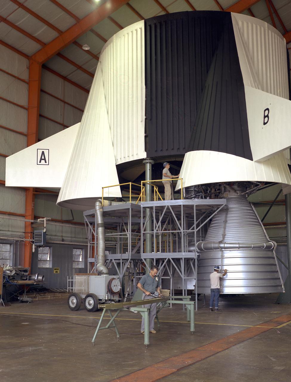
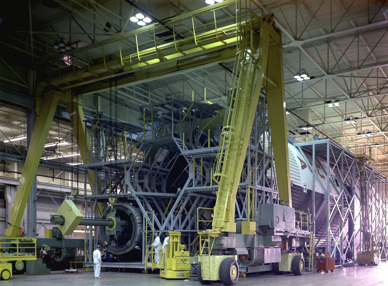
This image illustrates technicians working on a full scale engineering mock-up of a Saturn V S-IC stage thrust structure nearing completion at the Manufacturing Engineering Laboratory at Marshall Space Flight Center. The booster, 33 feet in diameter and 138 feet long, was powered by five F-1 engines that provided 7,500,000 pounds of thrust to start the monstrous vehicle on its journey into space.
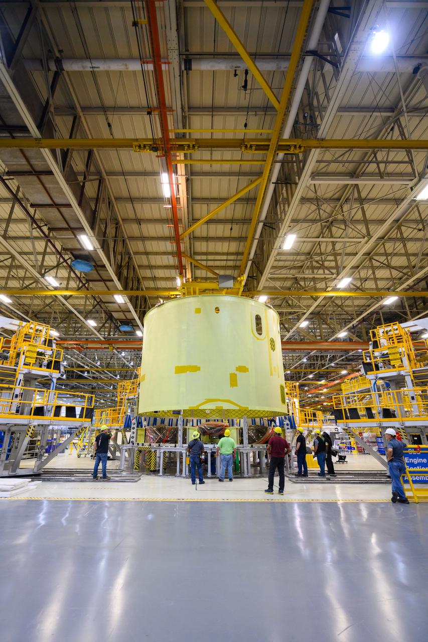
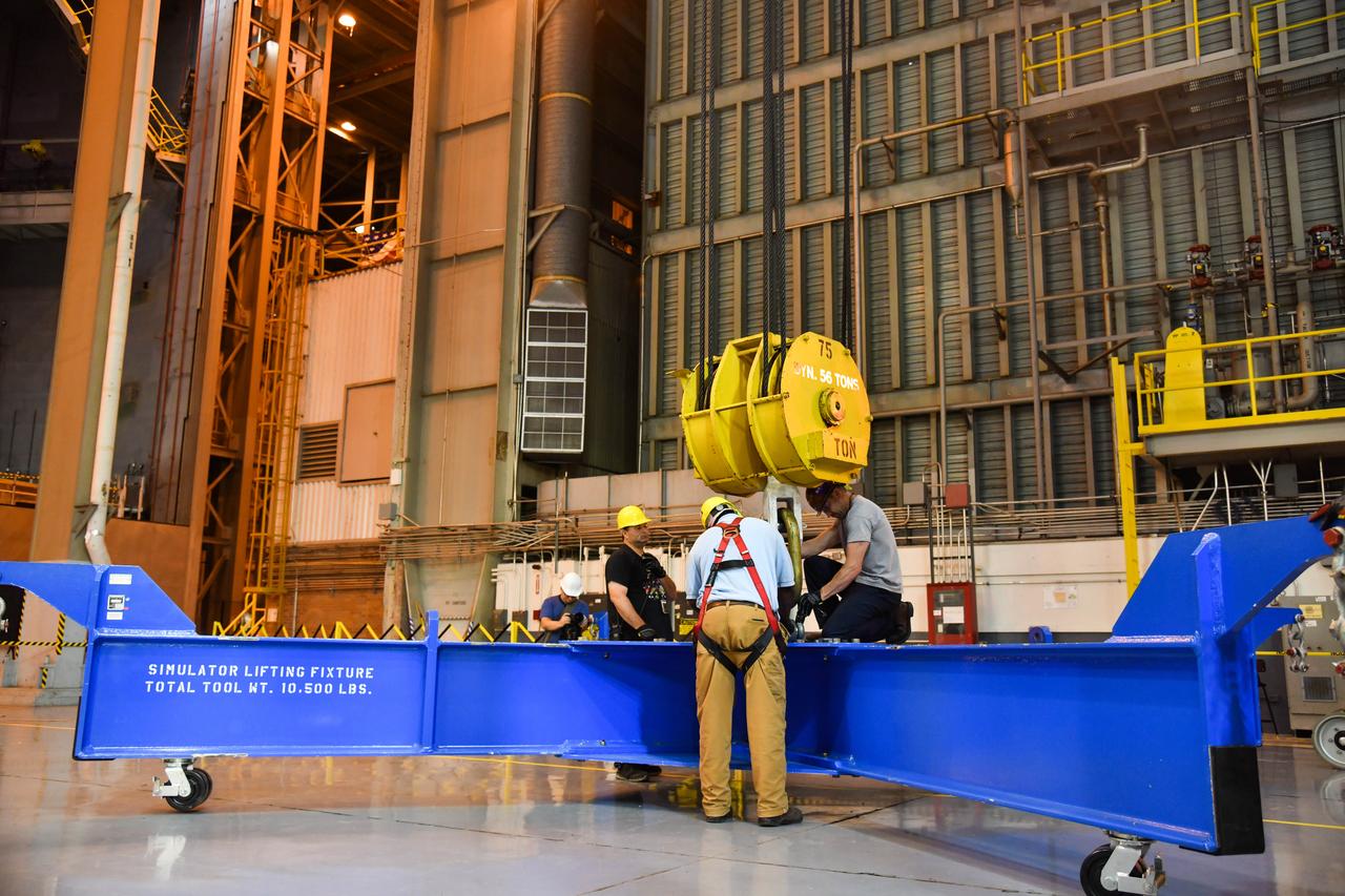
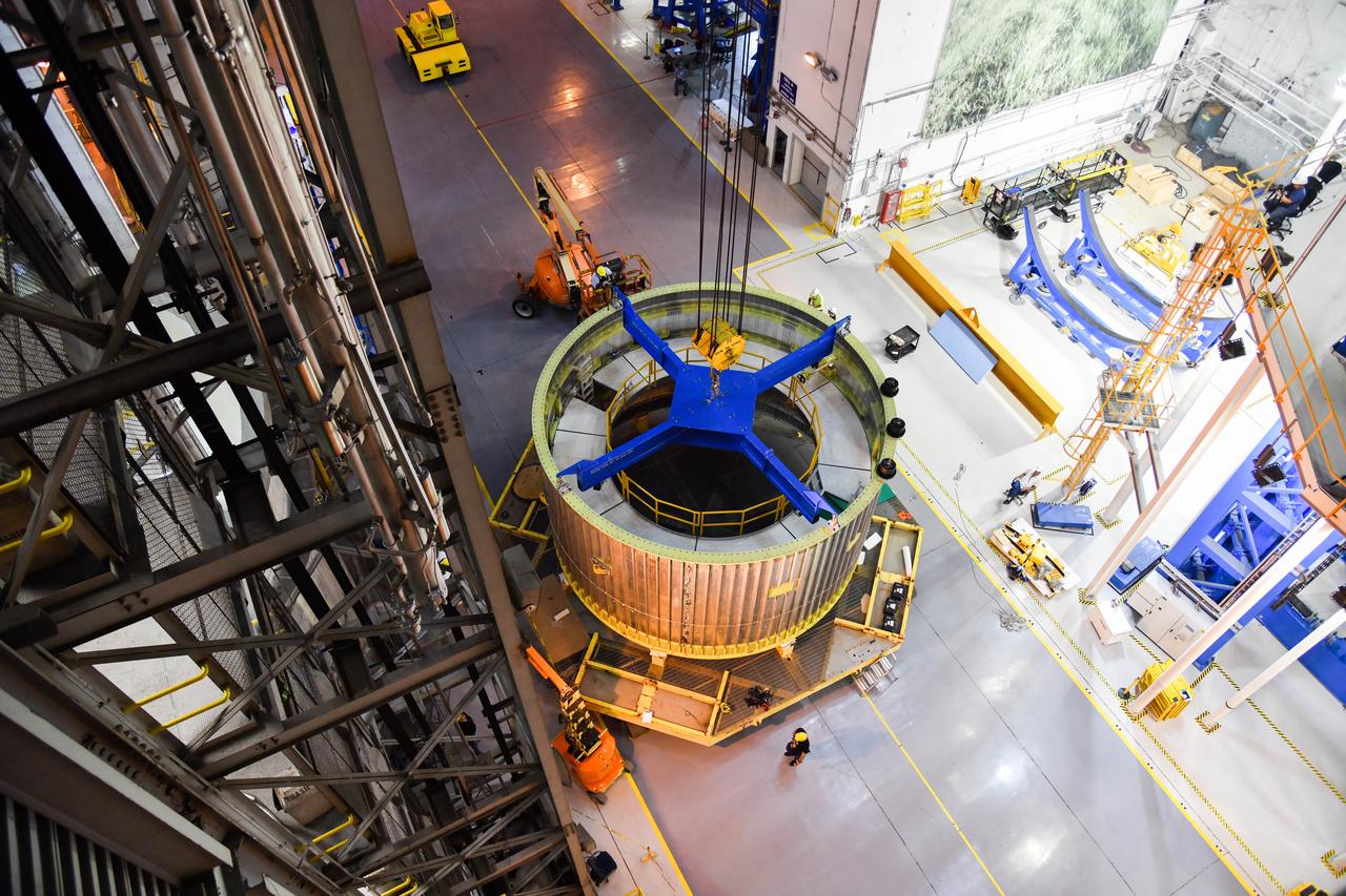
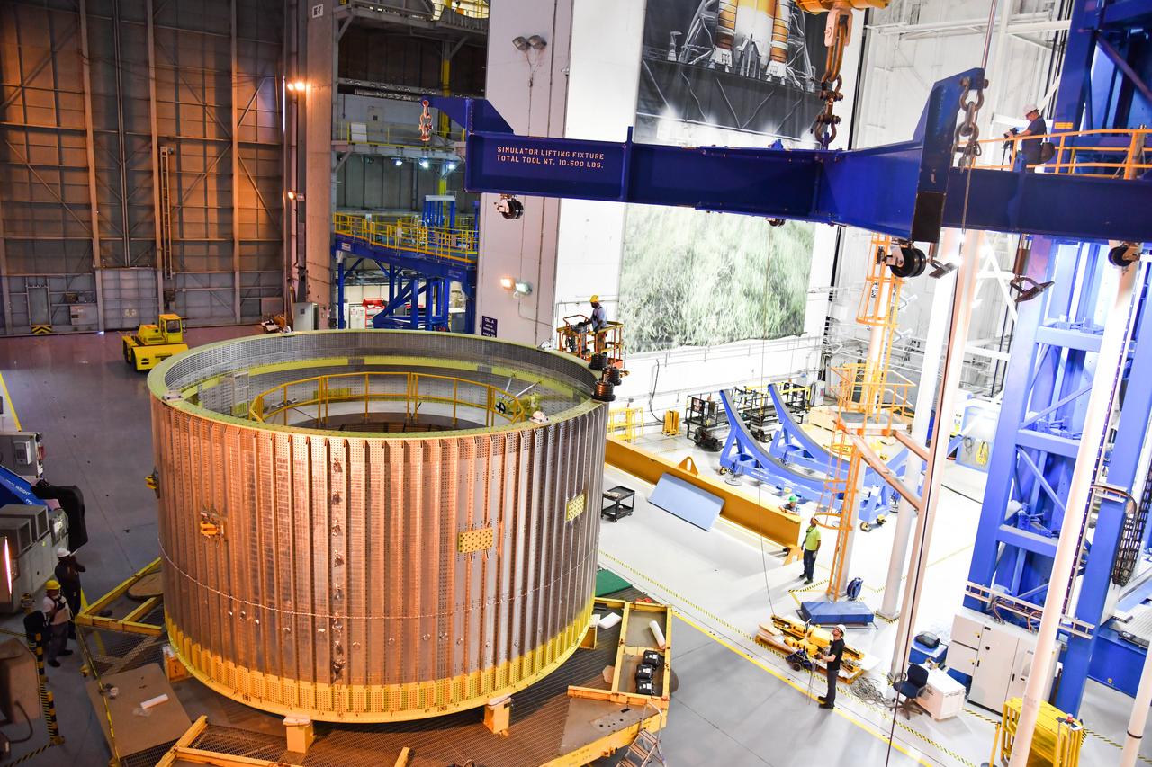
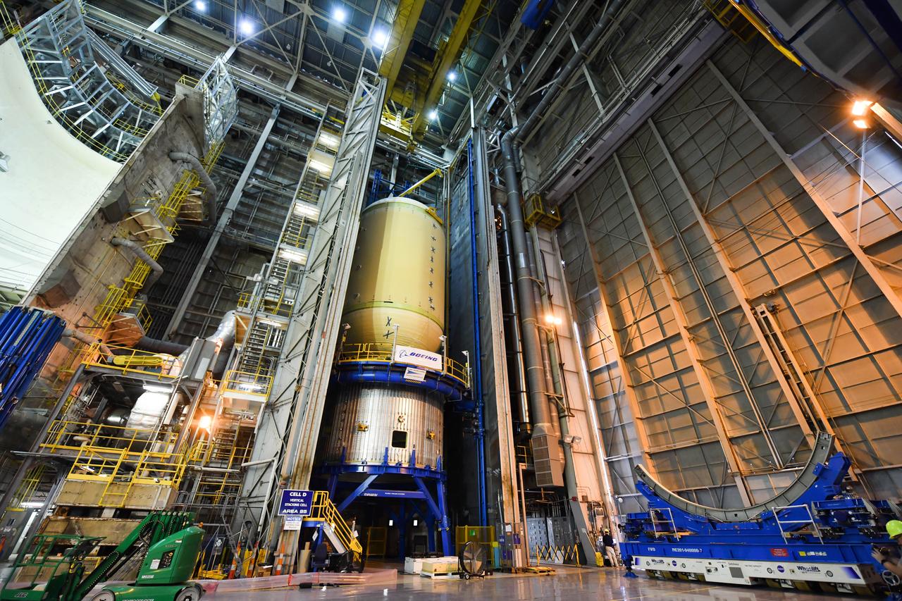
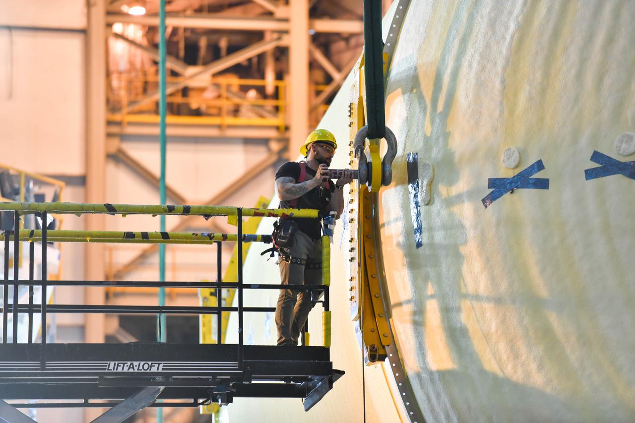
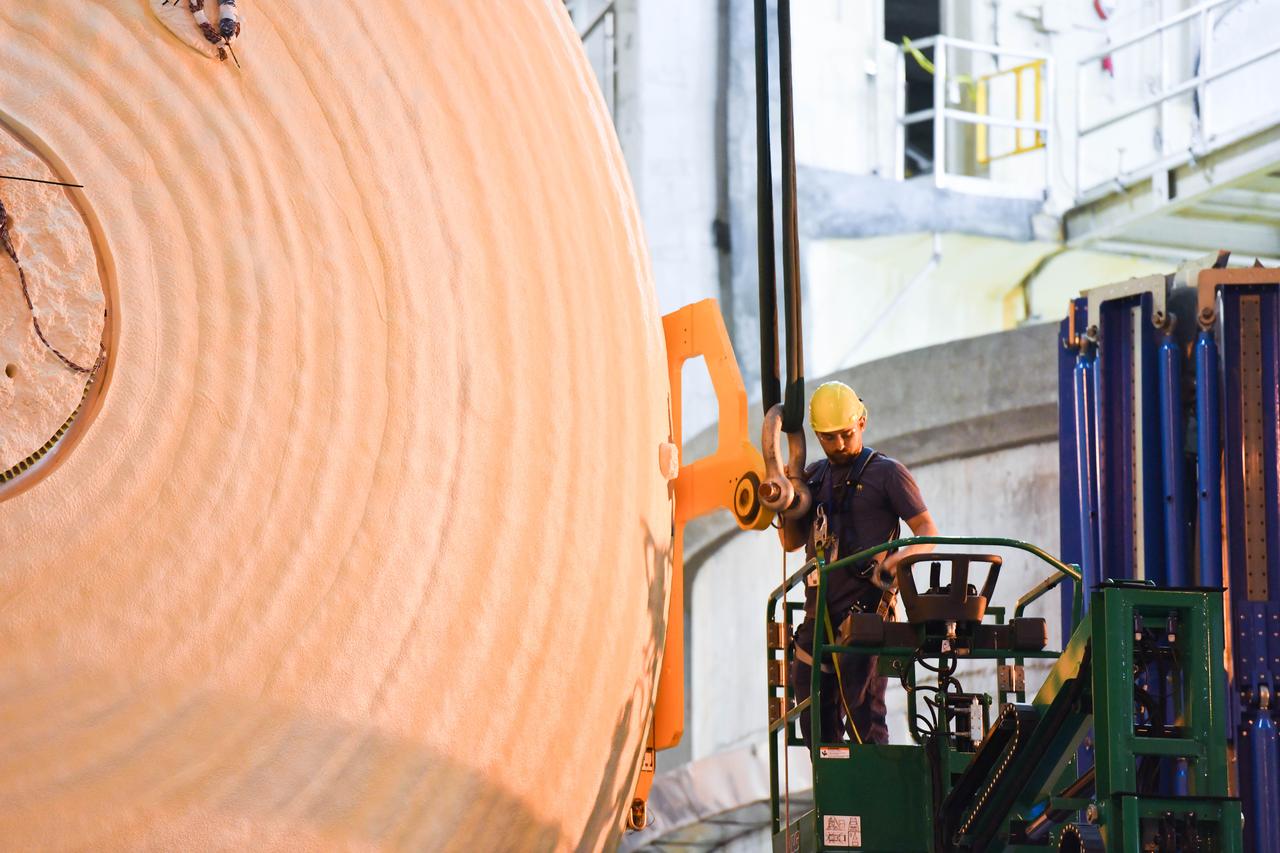
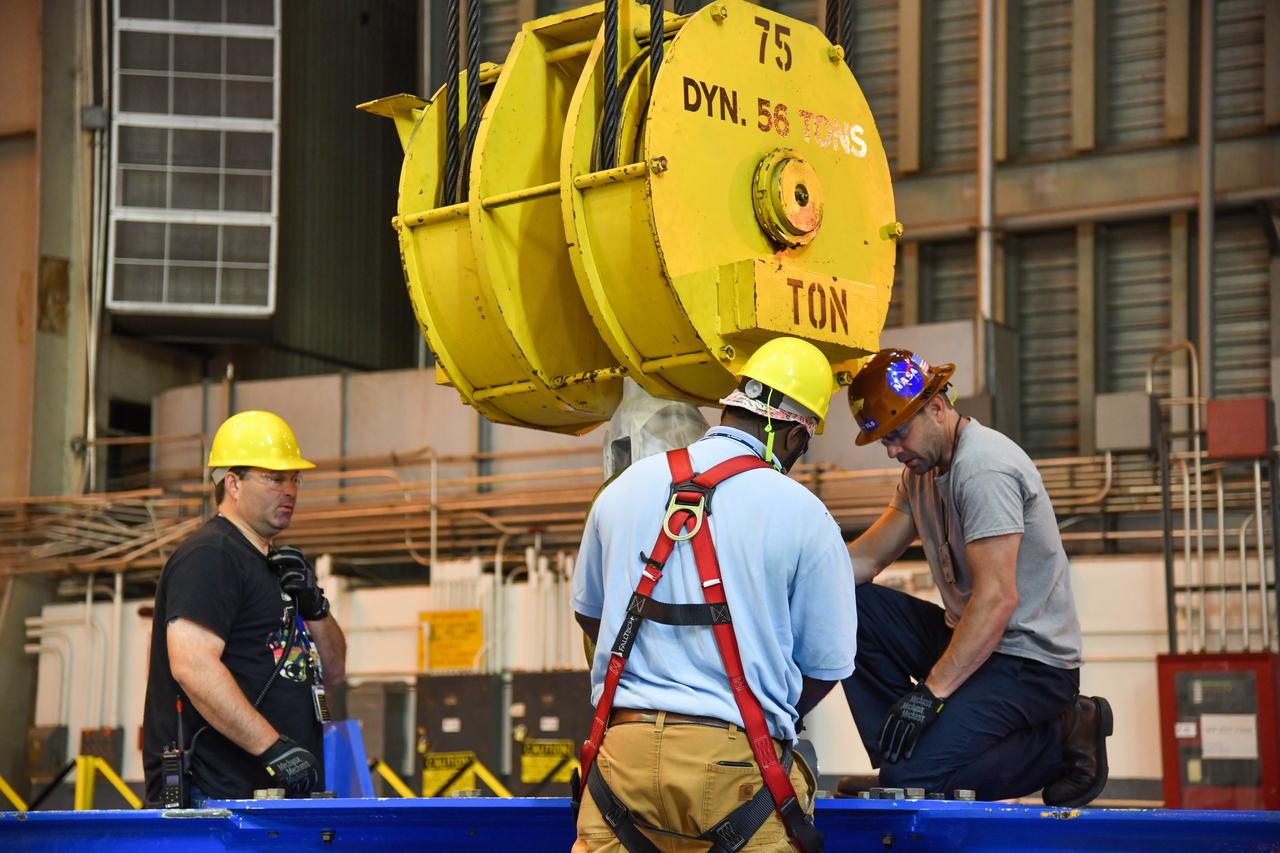
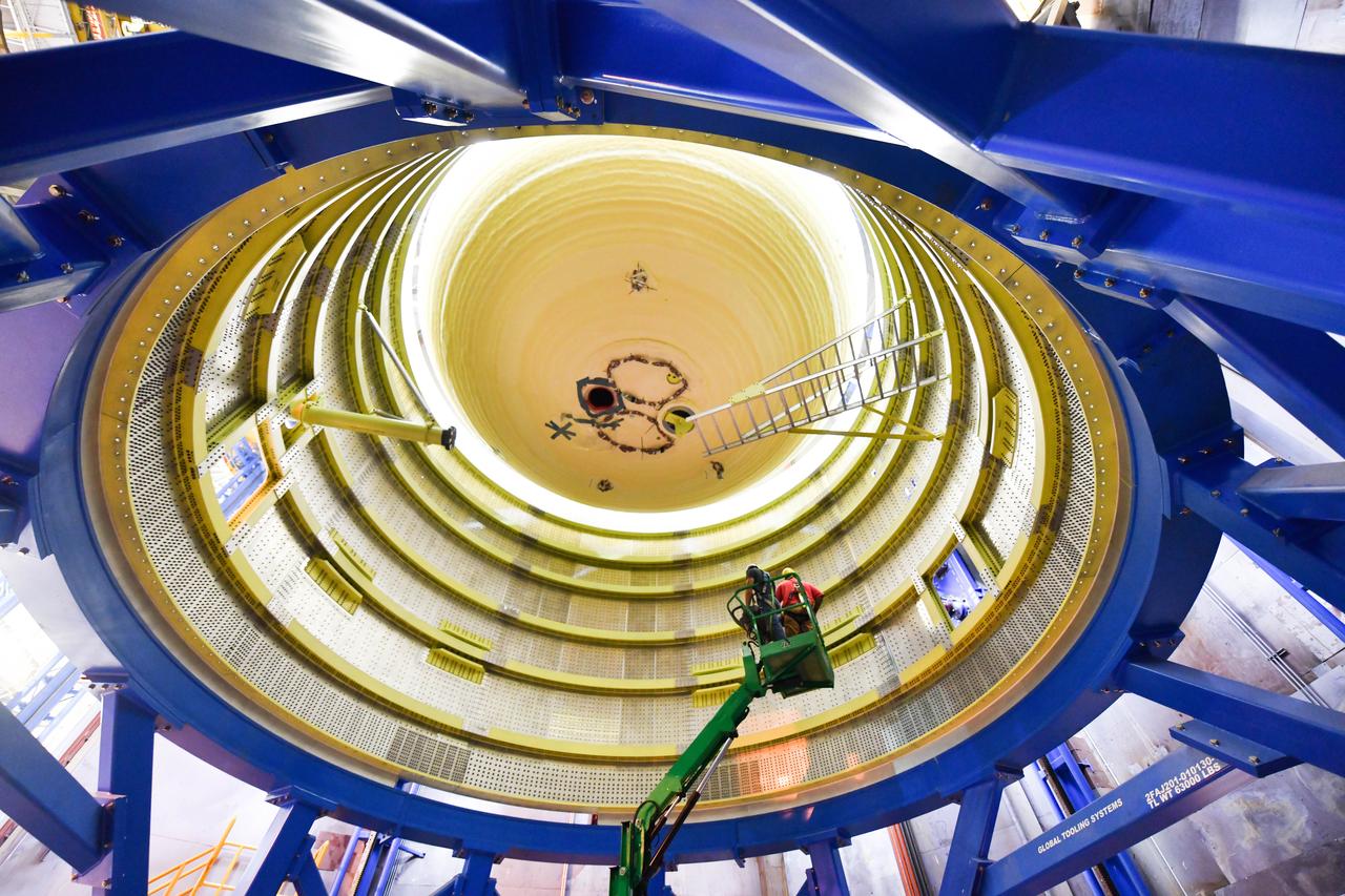
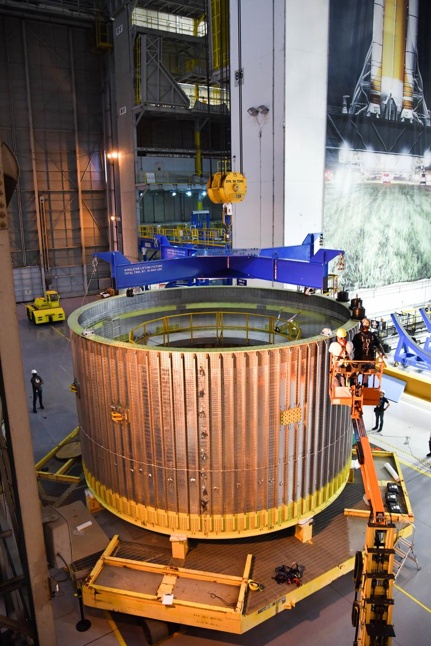
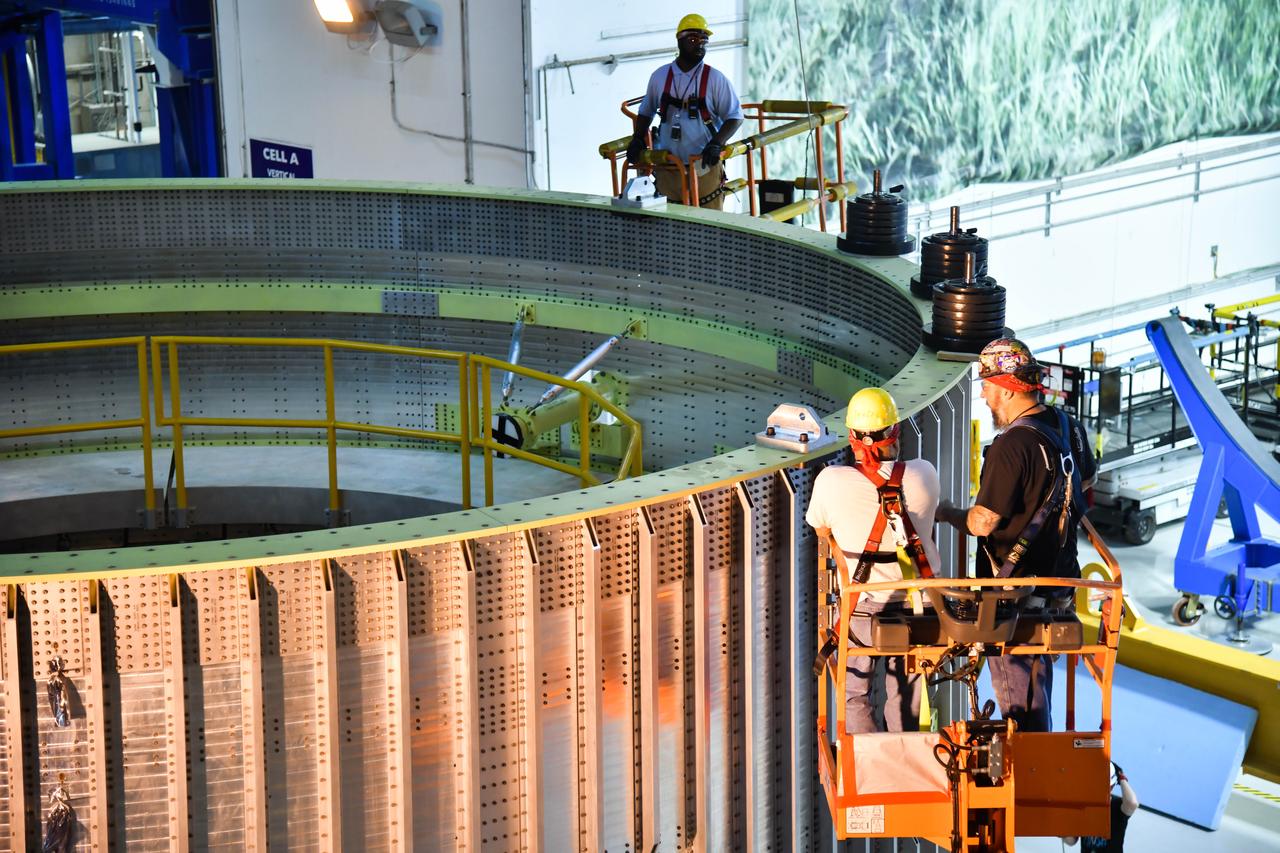
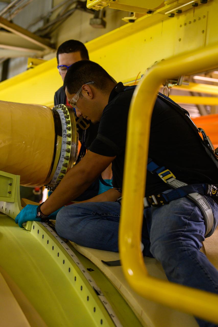
Space Launch System Corestage-2 Engine Section is lifted into a thrust structure tool at NASA's Michoud Assembly Facility.
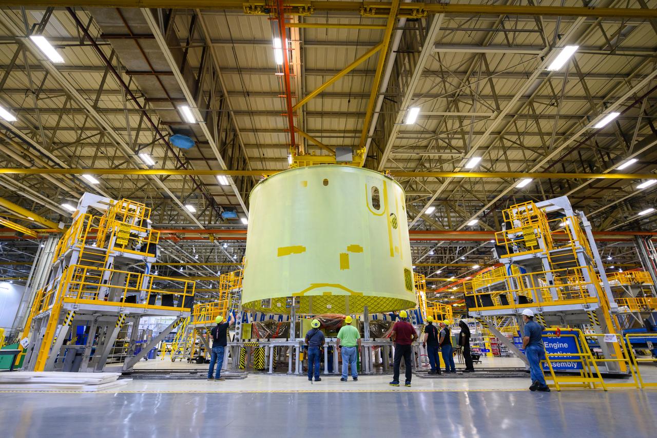
Space Launch System Corestage-2 Engine Section is lifted into a thrust structure tool at NASA's Michoud Assembly Facility.
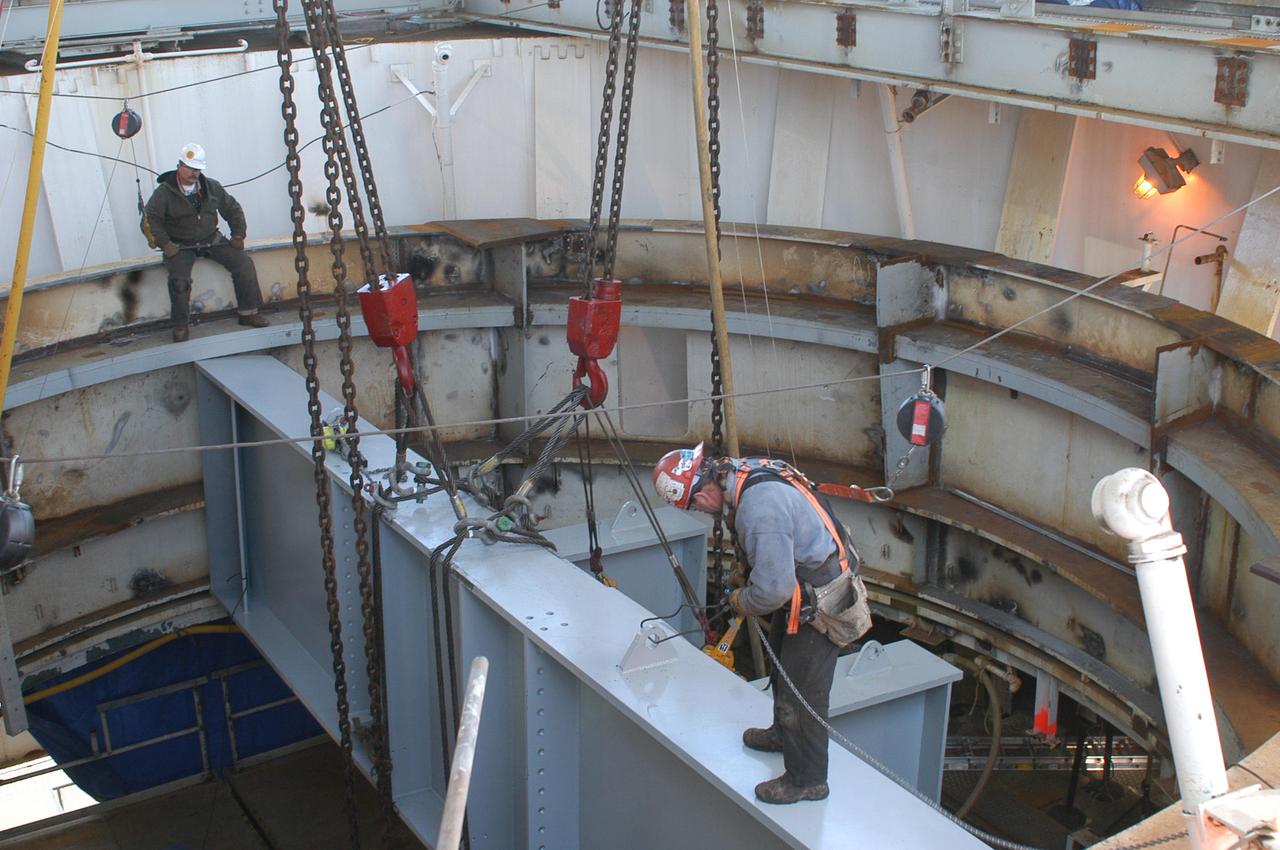
Employees at NASA's John C. Stennis Space Center work to maneuver a structural steam beam into place on the A-1 Test Stand on Jan. 13. The beam was one of several needed to form the thrust takeout structure that will support a new thrust measurement system being installed on the stand for future rocket engine testing. Once lifted onto the stand, the beams had to be hoisted into place through the center of the test stand, with only two inches of clearance on each side. The new thrust measurement system represents a state-of-the-art upgrade from the equipment installed more than 40 years ago when the test stand was first constructed.
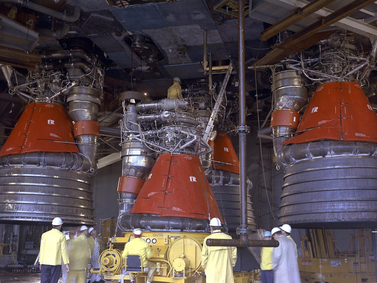
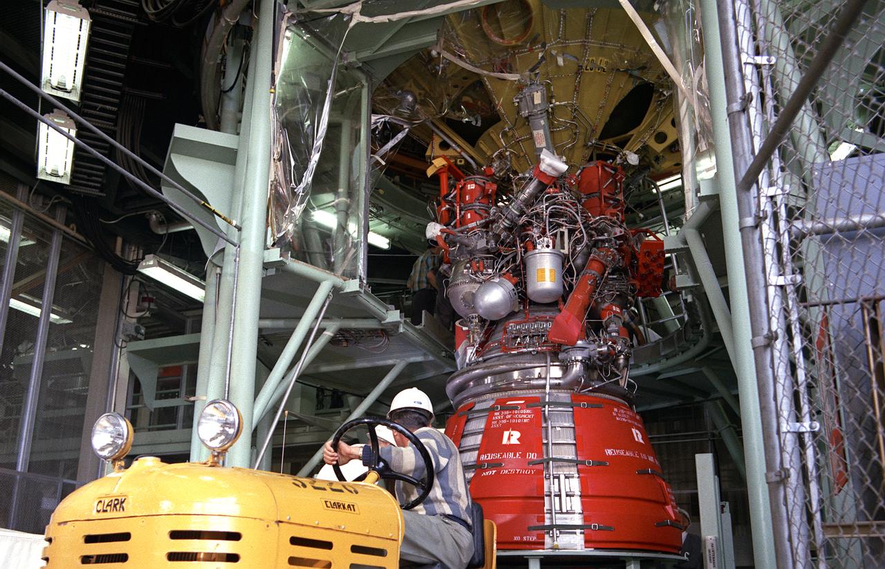
Engineers and technicians at the Marshall Space Flight Center were installing an F-I engine on the Saturn V S-IC (first) stage thrust structure in building 4705. The S-IC (first) stage used five F-1 engines that produced a total thrust of 7,500,000 pounds as each engine produced 1,500,000 pounds of thrust. The S-IC stage lifted the Saturn V vehicle and Apollo spacecraft from the launch pad.
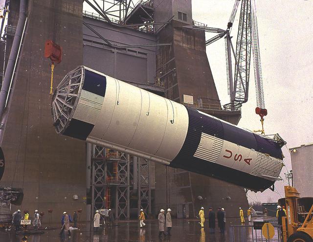
Workers at the Michoud Assembly Facility (MAF) near New Orleans, Louisiana, hoist the thrust structure assembly for the Saturn IB S-IB (first) stage. Developed by the Marshall Space Flight Center and built by the Chrysler Corporation at Michoud Assembly Facility (MAF), the S-IB utilized eight H-1 engines and each produced 200,000 pounds of thrust, a combined thrust of 1,600,000 pounds.
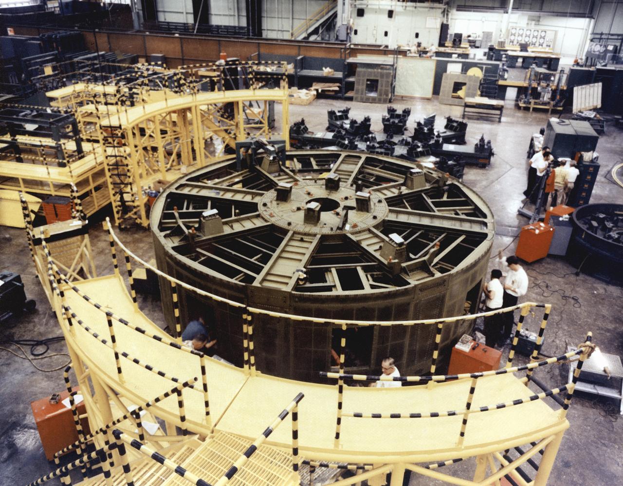
In one of the initial assembly steps for the Saturn IB launch vehicle's S-IB (first) stage, workers at the Michoud Assembly Facility (MAF) near New Orleans, Louisiana, complete the thrust structure. Developed by the Marshall Space Flight Center and built by the Chrysler Corporation at Michoud Assembly Facility (MAF), the S-IB utilized eight H-1 engines and each produced 200,000 pounds of thrust, a combined thrust of 1,600,000 pounds.
In one of the initial assembly steps for the Saturn IB launch vehicle's S-IB (first) stage, workers at the Michoud Assembly Facility (MAF) near New Orleans, Louisiana, position the thrust structure. Developed by the Marshall Space Flight Center and built by the Chrysler Corporation at Michoud Assembly Facility (MAF), the S-IB utilized eight H-1 engines and each produced 200,000 pounds of thrust, a combined thrust of 1,600,000 pounds.
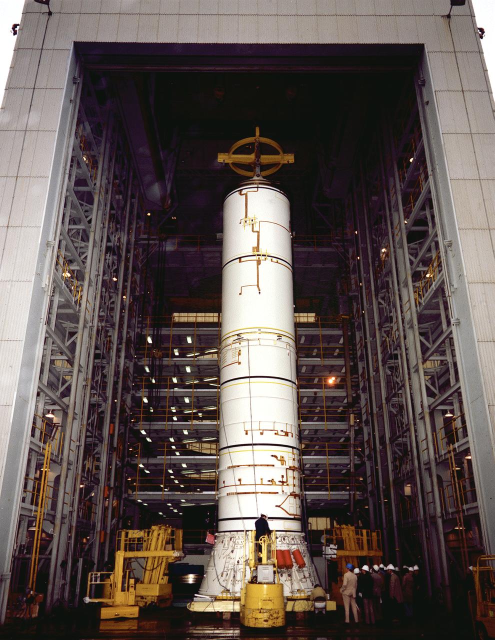
The structural test article to be used in the solid rocket booster (SRB) structural and load verification tests is being assembled in a high bay building of the Marshall Space Flight Center (MSFC). The Shuttle's two SRB's are the largest solids ever built and the first designed for refurbishment and reuse. Standing nearly 150-feet high, the twin boosters provide the majority of thrust for the first two minutes of flight, about 5.8 million pounds, augmenting the Shuttle's main propulsion system during liftoff. The major design drivers for the solid rocket motors (SRM's) were high thrust and reuse. The desired thrust was achieved by using state-of-the-art solid propellant and by using a long cylindrical motor with a specific core design that allows the propellant to burn in a carefully controlled marner. At burnout, the boosters separate from the external tank and drop by parachute to the ocean for recovery and subsequent refurbishment.
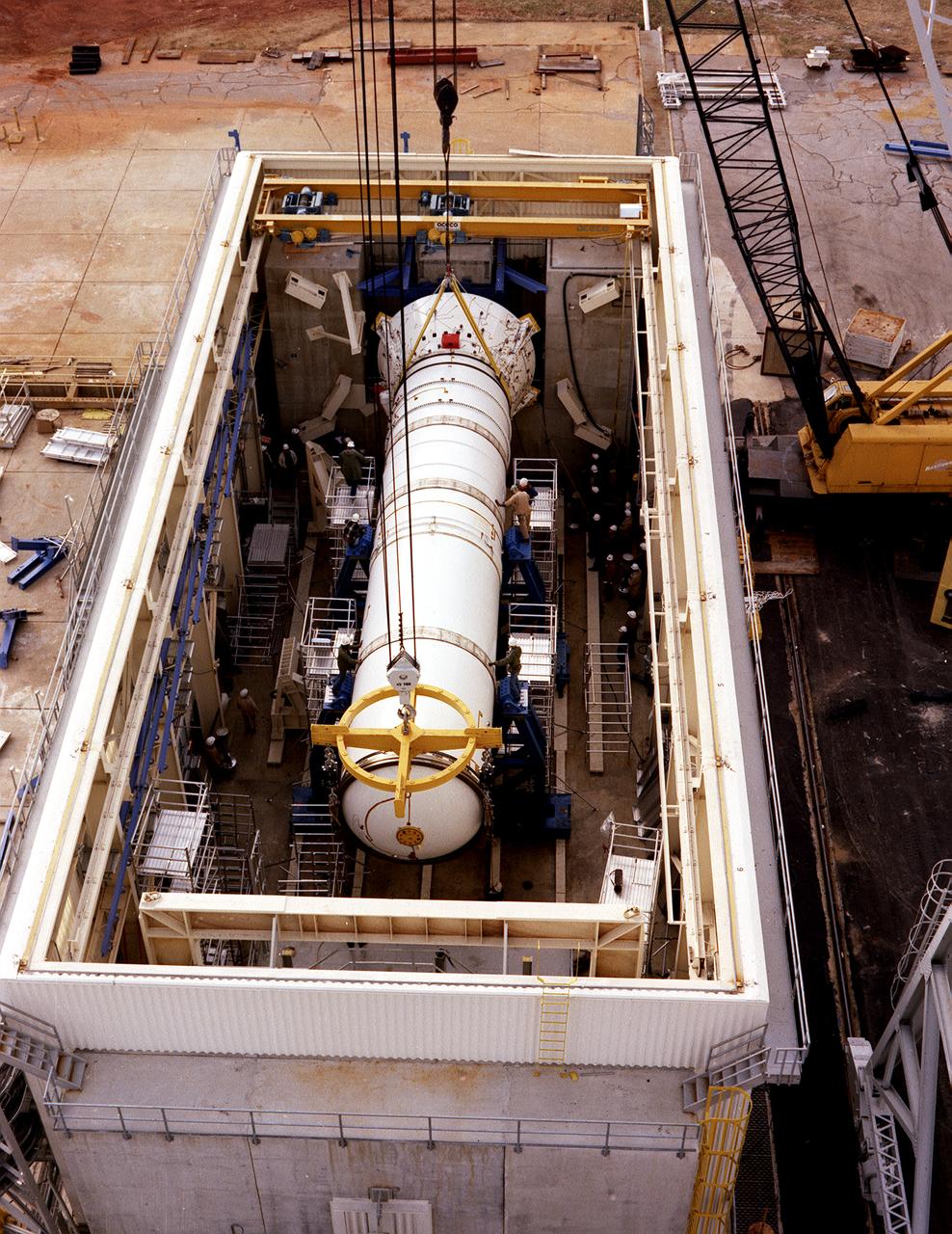
The solid rocket booster (SRB) structural test article is being installed in the Solid Rocket Booster Test Facility for the structural and load verification test at the Marshall Space Flight Center (MSFC). The Shuttle's two SRB's are the largest solids ever built and the first designed for refurbishment and reuse. Standing nearly 150-feet high, the twin boosters provide the majority of thrust for the first two minutes of flight, about 5.8 million pounds, augmenting the Shuttle's main propulsion system during liftoff. The major design drivers for the solid rocket motors (SRM's) were high thrust and reuse. The desired thrust was achieved by using state-of-the-art solid propellant and by using a long cylindrical motor with a specific core design that allows the propellant to burn in a carefully controlled marner. At burnout, the boosters separate from the external tank and drop by parachute to the ocean for recovery and subsequent refurbishment.
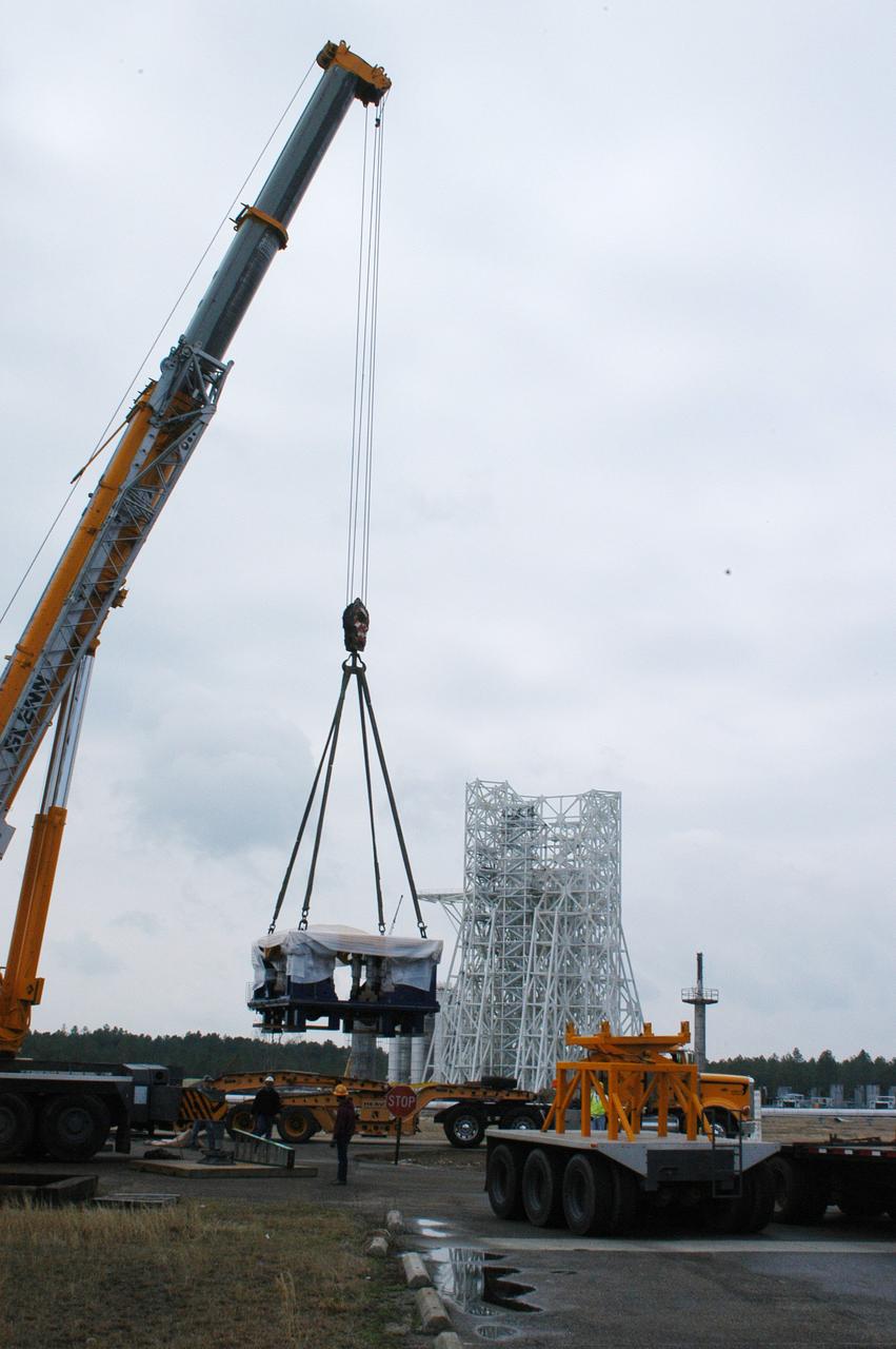
A state-of-the-art thrust measurement system for the A-3 Test Stand under construction at NASA's John C. Stennis Space Center was delivered March 17. Once completed, the A-3 stand (seen in background) will allow simulated high-altitude testing on the next generation of rocket engines for America's space program. Work on the stand began in 2007, with activation scheduled for 2012. The stand is the first major test structure to be built at Stennis since the 1960s. The recently delivered TMS was fabricated by Thrust Measurement Systems in Illinois. It is an advanced calibration system capable of measuring vertical and horizontal thrust loads with an accuracy within 0.15 percent at 225,000 pounds.
This image shows the Saturn V S-IC-T stage (S-IC static test article) fuel tank being attached to the thrust structure in the vehicle assembly building at the Marshall Space Flight Center (MSFC). The S-IC stage utilized five F-1 engines that used liquid oxygen and kerosene as propellant and provided a combined thrust of 7,500,000 pounds.
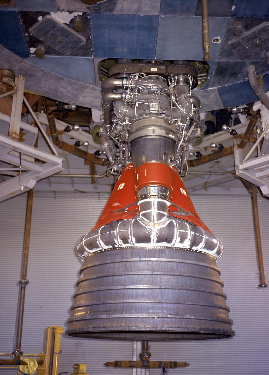
Engineers at the Marshall Space Flight Center install the F-1 engines on the S-IC stage thrust structure at the S-IC static test stand. Engines are installed on the stage after it has been placed in the test stand. This image shows a close-up of an F-1 engine. Five F-1 engines, each weighing 10 tons, gave the booster a total thrust of 7,500,000 pounds, roughly equivalent to 160 million horsepower.
Engineers at the Marshall Space Flight Center install the F-1 engines on the S-IC stage thrust structure at the S-IC static test stand. Engines are installed on the stage after it has been placed in the test stand. Five F-1 engines, each weighing 10 tons, gave the booster a total thrust of 7,500,000 pounds, roughly equivalent to 160 million horsepower.
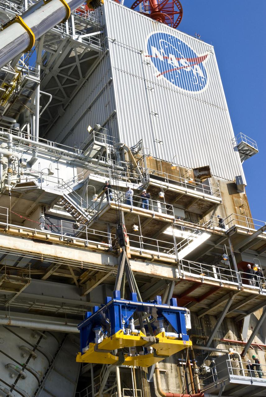
A new thrust measurement system is lifted onto the A-1 Test Stand deck at NASA's John C. Stennis Space Center in preparation for its installation. The new system is a state-of-the-art upgrade for the testing structure, which is being prepared for testing of next-generation rocket engines. The system was fabricated by Thrust Measurement Systems in Illinois at a cost of about $3.5 million.
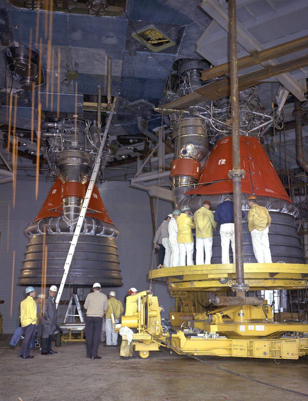
Engineers at the Marshall Space Flight Center install the F-1 engines on the S-IC stage thrust structure at the S-IC static test stand. Engines are installed on the stage after it has been placed in the test stand. Five F-1 engines, each weighing 10 tons, gave the booster a total thrust of 7,500,000 pounds, roughly equivalent to 160 million horsepower.
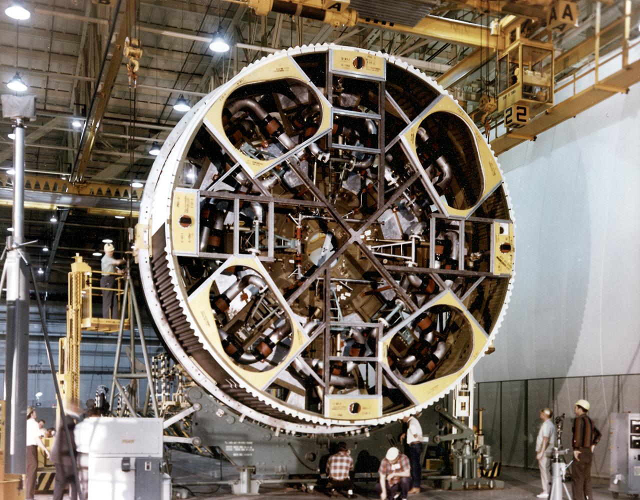
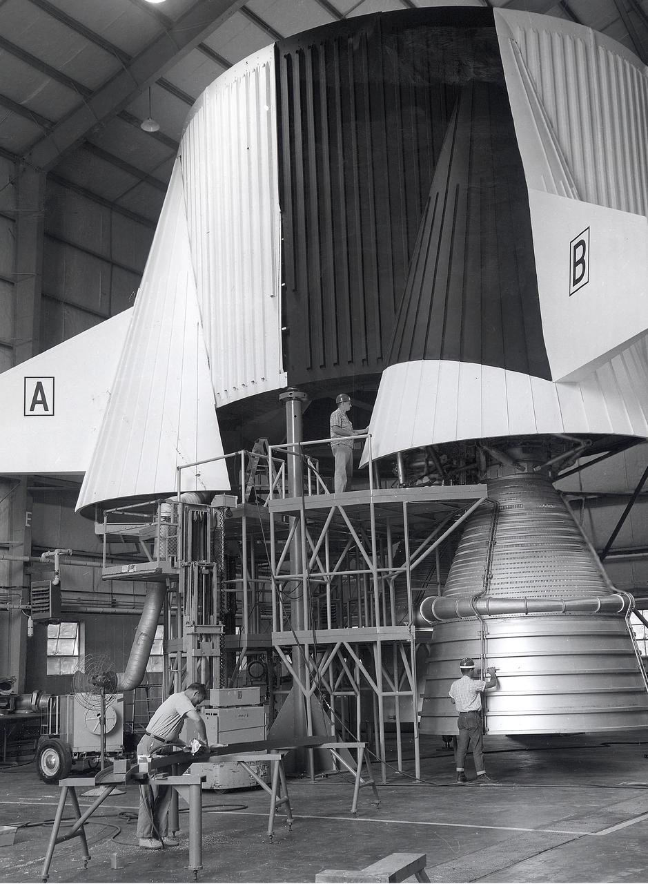
Workmen secure a J-2 engine onto the S-IVB (second) stage thrust structure. As part of Marshall Space Center's "building block" approach to the Saturn development, the S-IVB was utilized in the Saturn IBC launch vehicle as a second stage and the Saturn V launch vehicle as a third stage. The booster, built for NASA by McDornell Douglas Corporation, was powered by a single J-2 engine, initially capable of 200,000 pounds of thrust.
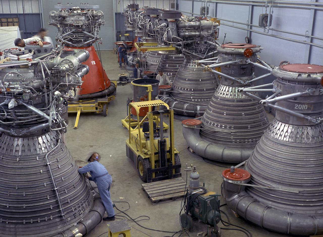
This photograph shows F-1 engines being stored in the F-1 Engine Preparation Shop, building 4666, at the Marshall Space Flight Center. Each F-1 engine produced a thrust of 1,500,000 pounds. A cluster of five engines was mounted on the thrust structure of the S-IC stage of a 364-foot long Saturn V launch vehicle that ultimately took astronauts to the Moon.

Photo shows how the Space Launch Sysetm (SLS) rocket liquid oxygen tank failed during a structural qualification test at NASA’s Marshall Space Flight Center in Huntsville, Alabama. The photos show both the water flowing from the tank as it ruptured and the resultant tear left in the tank when it buckled during the test. Engineers pushed the liquid oxygen structural test article to the limits on purpose. The tank is a test article that is identical to tanks that are part of the SLS core stage that will produce 2 million pounds of thrust to help launch the rocket on the Artemis missions to the Moon. During the test, hydraulic cylinders were then calibrated and positioned along the tank to apply millions of pounds of crippling force from all sides while engineers measured and recorded the effects of the launch and flight forces. For the test, water used to simulate the liquid oxygen flows out of the tank after it ruptures. The structural test campaign was conducted on the rocket to ensure the SLS rocket’s structure can endure the rigors of launch and safely send astronauts to the Moon on the Artemis missions. For more information: https://www.nasa.gov/exploration/systems/sls/nasa-completes-artemis-sls-structural-testing-campaign.html

Photo shows how the Space Launch Sysetm (SLS) rocket liquid oxygen tank failed during a structural qualification test at NASA’s Marshall Space Flight Center in Huntsville, Alabama. The photos show both the water flowing from the tank as it ruptured and the resultant tear left in the tank when it buckled during the test. Engineers pushed the liquid oxygen structural test article to the limits on purpose. The tank is a test article that is identical to tanks that are part of the SLS core stage that will produce 2 million pounds of thrust to help launch the rocket on the Artemis missions to the Moon. During the test, hydraulic cylinders were then calibrated and positioned along the tank to apply millions of pounds of crippling force from all sides while engineers measured and recorded the effects of the launch and flight forces. For the test, water used to simulate the liquid oxygen flows out of the tank after it ruptures. The structural test campaign was conducted on the rocket to ensure the SLS rocket’s structure can endure the rigors of launch and safely send astronauts to the Moon on the Artemis missions. For more information: https://www.nasa.gov/exploration/systems/sls/nasa-completes-artemis-sls-structural-testing-campaign.html

Photo shows how the Space Launch Sysetm (SLS) rocket liquid oxygen tank failed during a structural qualification test at NASA’s Marshall Space Flight Center in Huntsville, Alabama. The photos show both the water flowing from the tank as it ruptured and the resultant tear left in the tank when it buckled during the test. Engineers pushed the liquid oxygen structural test article to the limits on purpose. The tank is a test article that is identical to tanks that are part of the SLS core stage that will produce 2 million pounds of thrust to help launch the rocket on the Artemis missions to the Moon. During the test, hydraulic cylinders were then calibrated and positioned along the tank to apply millions of pounds of crippling force from all sides while engineers measured and recorded the effects of the launch and flight forces. For the test, water used to simulate the liquid oxygen flows out of the tank after it ruptures. The structural test campaign was conducted on the rocket to ensure the SLS rocket’s structure can endure the rigors of launch and safely send astronauts to the Moon on the Artemis missions. For more information: https://www.nasa.gov/exploration/systems/sls/nasa-completes-artemis-sls-structural-testing-campaign.html

Photo shows how the Space Launch Sysetm (SLS) rocket liquid oxygen tank failed during a structural qualification test at NASA’s Marshall Space Flight Center in Huntsville, Alabama. The photos show both the water flowing from the tank as it ruptured and the resultant tear left in the tank when it buckled during the test. Engineers pushed the liquid oxygen structural test article to the limits on purpose. The tank is a test article that is identical to tanks that are part of the SLS core stage that will produce 2 million pounds of thrust to help launch the rocket on the Artemis missions to the Moon. During the test, hydraulic cylinders were then calibrated and positioned along the tank to apply millions of pounds of crippling force from all sides while engineers measured and recorded the effects of the launch and flight forces. For the test, water used to simulate the liquid oxygen flows out of the tank after it ruptures. The structural test campaign was conducted on the rocket to ensure the SLS rocket’s structure can endure the rigors of launch and safely send astronauts to the Moon on the Artemis missions. For more information: https://www.nasa.gov/exploration/systems/sls/nasa-completes-artemis-sls-structural-testing-campaign.html
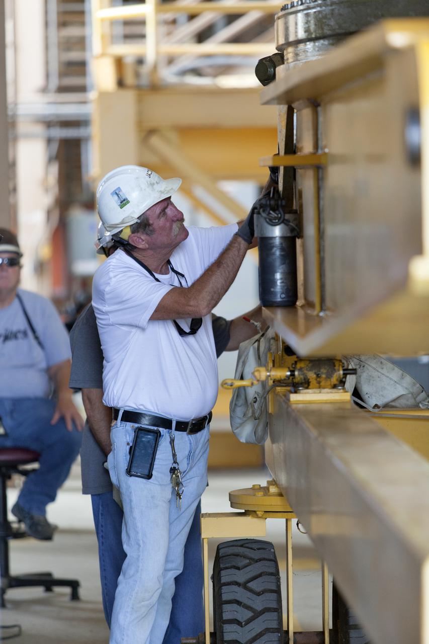
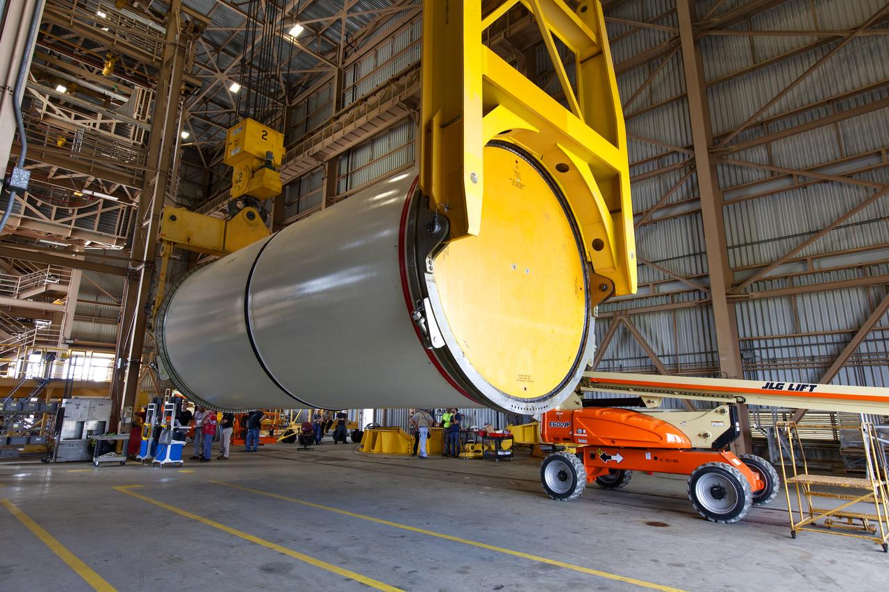
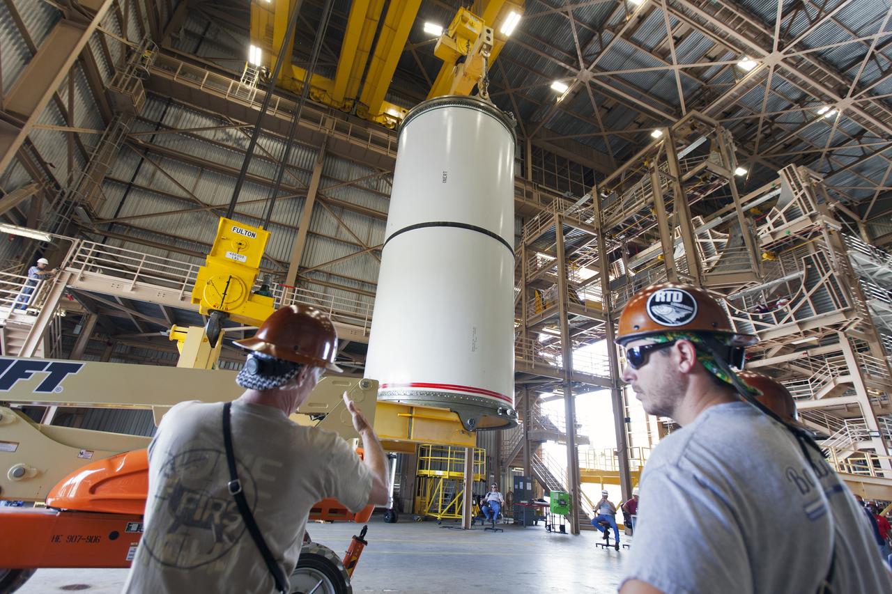
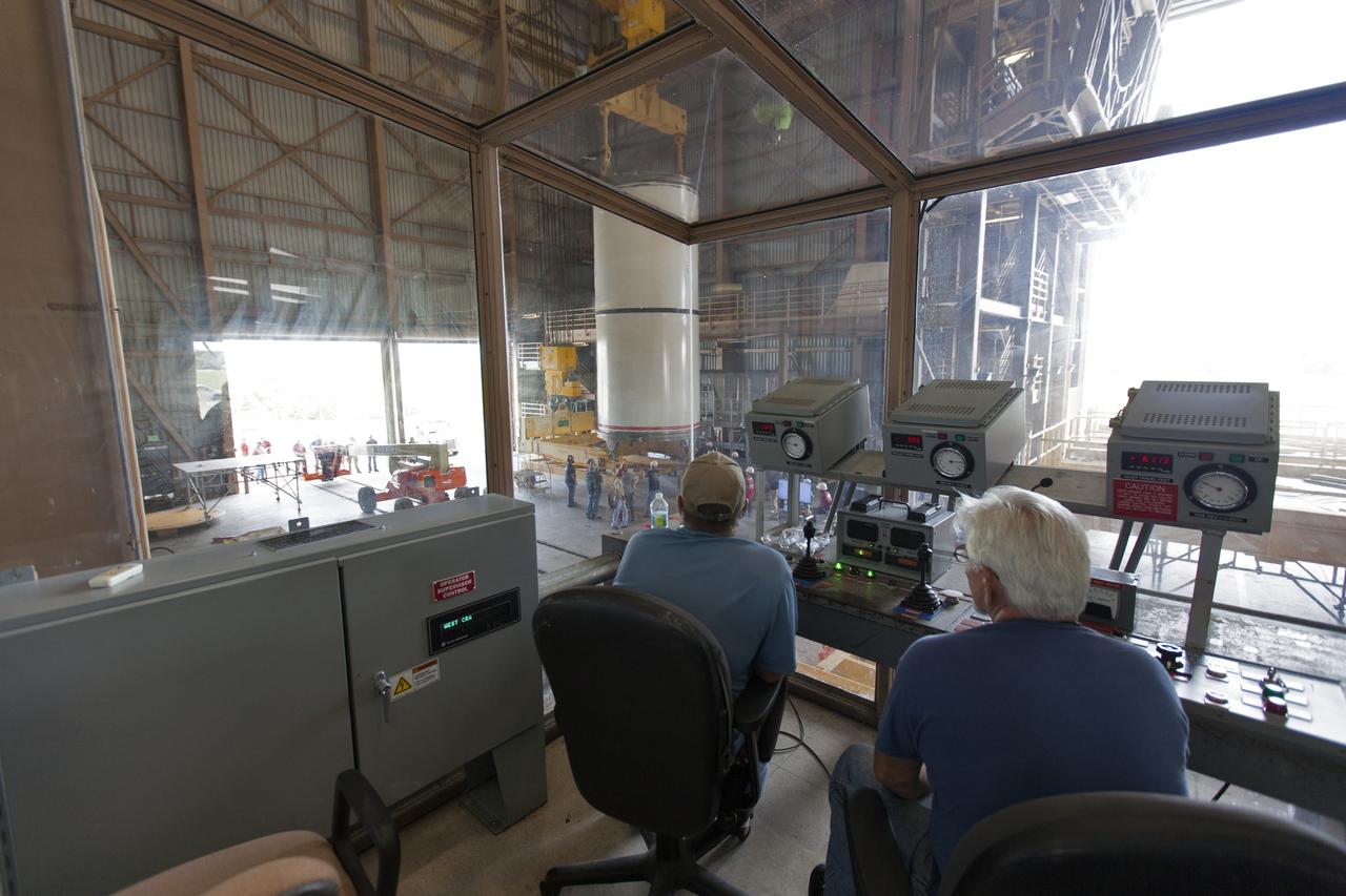
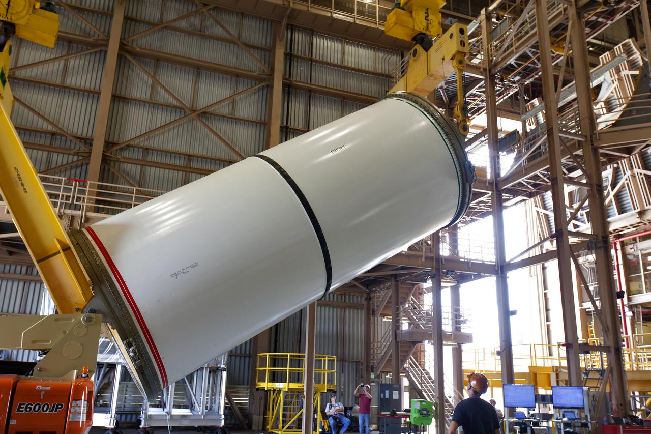
A Jacobs technician, on the Test and Operations Support Contract, checks bolt fittings during practice crane operations with an inert booster rocket segment in the Rotation, Processing and Surge Facility on June 22, 2018, at NASA's Kennedy Space Center in Florida. Dual cranes will be used to move the segment from vertical to horizontal, a maneuver known as a "breakover rotation." As part of routine processing operations for the agency's Space Launch System (SLS) rocket, the RPSF team will receive all of the solid rocket fuel segments for inspection and preparation prior to transporting them to the Vehicle Assembly Building for stacking on the mobile launcher. Many pathfinding operations are being done to prepare for launch of the SLS and Orion spacecraft on Exploration Mission-1 and deep space missions.
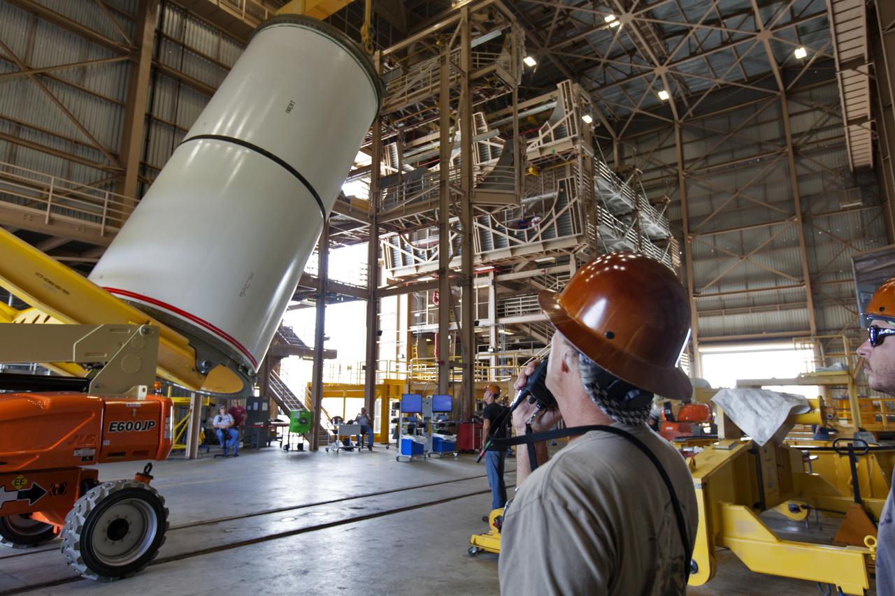
Jacobs technicians, on the Test and Operations Support Contract, practice crane operations with an inert booster rocket segment in the Rotation, Processing and Surge Facility on June 22, 2018, at NASA's Kennedy Space Center in Florida. Dual cranes are being used to move the segment from vertical to horizontal, a maneuver known as a "breakover rotation." As part of routine processing operations for the agency's Space Launch System (SLS) rocket, the RPSF team will receive all of the solid rocket fuel segments for inspection and preparation prior to transporting them to the Vehicle Assembly Building for stacking on the mobile launcher. Many pathfinding operations are being done to prepare for launch of the SLS and Orion spacecraft on Exploration Mission-1 and deep space missions.
Jacobs technicians, on the Test and Operations Support Contract, practice crane operations with an inert booster rocket segment in the Rotation, Processing and Surge Facility on June 22, 2018, at NASA's Kennedy Space Center in Florida. Dual cranes were used to move the segment from vertical to horizontal, a maneuver known as a "breakover rotation." As part of routine processing operations for the agency's Space Launch System (SLS) rocket, the RPSF team will receive all of the solid rocket fuel segments for inspection and preparation prior to transporting them to the Vehicle Assembly Building for stacking on the mobile launcher. Many pathfinding operations are being done to prepare for launch of the SLS and Orion spacecraft on Exploration Mission-1 and deep space missions.
Jacobs technicians, on the Test and Operations Support Contract, practice crane operations with an inert booster rocket segment in the Rotation, Processing and Surge Facility on June 22, 2018, at NASA's Kennedy Space Center in Florida. Dual cranes are used to move the segment from vertical to horizontal, a maneuver known as a "breakover rotation." As part of routine processing operations for the agency's Space Launch System (SLS) rocket, the RPSF team will receive all of the solid rocket fuel segments for inspection and preparation prior to transporting them to the Vehicle Assembly Building for stacking on the mobile launcher. Many pathfinding operations are being done to prepare for launch of the SLS and Orion spacecraft on Exploration Mission-1 and deep space missions.
Jacobs technicians, on the Test and Operations Support Contract, practice crane operations with an inert booster rocket segment in the Rotation, Processing and Surge Facility on June 22, 2018, at NASA's Kennedy Space Center in Florida. Dual cranes are being used to move the segment from vertical to horizontal, a maneuver known as a "breakover rotation." As part of routine processing operations for the agency's Space Launch System (SLS) rocket, the RPSF team will receive all of the solid rocket fuel segments for inspection and preparation prior to transporting them to the Vehicle Assembly Building for stacking on the mobile launcher. Many pathfinding operations are being done to prepare for launch of the SLS and Orion spacecraft on Exploration Mission-1 and deep space missions.
Jacobs technicians, on the Test and Operations Support Contract, practice crane operations with an inert booster rocket segment in the Rotation, Processing and Surge Facility on June 22, 2018, at NASA's Kennedy Space Center in Florida. Dual cranes are being used to move the segment from vertical to horizontal, a maneuver known as a "breakover rotation." As part of routine processing operations for the agency's Space Launch System (SLS) rocket, the RPSF team will receive all of the solid rocket fuel segments for inspection and preparation prior to transporting them to the Vehicle Assembly Building for stacking on the mobile launcher. Many pathfinding operations are being done to prepare for launch of the SLS and Orion spacecraft on Exploration Mission-1 and deep space missions.
Jacobs technicians, on the Test and Operations Support Contract, practice crane operations with an inert booster rocket segment in the Rotation, Processing and Surge Facility on June 22, 2018, at NASA's Kennedy Space Center in Florida. Dual cranes are being used to move the segment from vertical to horizontal, a maneuver known as a "breakover rotation." As part of routine processing operations for the agency's Space Launch System (SLS) rocket, the RPSF team will receive all of the solid rocket fuel segments for inspection and preparation prior to transporting them to the Vehicle Assembly Building for stacking on the mobile launcher. Many pathfinding operations are being done to prepare for launch of the SLS and Orion spacecraft on Exploration Mission-1 and deep space missions.
Jacobs technicians, on the Test and Operations Support Contract, practice crane operations with an inert booster rocket segment in the Rotation, Processing and Surge Facility on June 22, 2018, at NASA's Kennedy Space Center in Florida. Dual cranes are being used to move the segment from vertical to horizontal, a maneuver known as a "breakover rotation." As part of routine processing operations for the agency's Space Launch System (SLS) rocket, the RPSF team will receive all of the solid rocket fuel segments for inspection and preparation prior to transporting them to the Vehicle Assembly Building for stacking on the mobile launcher. Many pathfinding operations are being done to prepare for launch of the SLS and Orion spacecraft on Exploration Mission-1 and deep space missions.
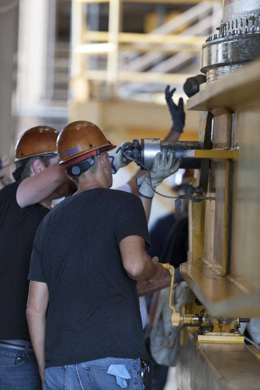
Jacobs technicians, on the Test and Operations Support Contract, check bolt fittings as they practice crane operations with an inert booster rocket segment in the Rotation, Processing and Surge Facility on June 22, 2018, at NASA's Kennedy Space Center in Florida. Dual cranes are being used to move the segment from vertical to horizontal, a maneuver known as a "breakover rotation." As part of routine processing operations for the agency's Space Launch System (SS) rocket, the RPSF team will receive all of the solid rocket fuel segments for inspection and preparation prior to transporting them to the Vehicle Assembly Building for stacking on the mobile launcher. Many pathfinding operations are being done to prepare for launch of the SLS and Orion spacecraft on Exploration Mission-1 and deep space missions.
Jacobs technicians, on the Test and Operations Support Contract, practice crane operations with an inert booster rocket segment in the Rotation, Processing and Surge Facility on June 22, 2018, at NASA's Kennedy Space Center in Florida. Dual cranes are being used to move the segment from vertical to horizontal, a maneuver known as a "breakover rotation." As part of routine processing operations for the agency's Space Launch System (SLS) rocket, the RPSF team will receive all of the solid rocket fuel segments for inspection and preparation prior to transporting them to the Vehicle Assembly Building for stacking on the mobile launcher. Many pathfinding operations are being done to prepare for launch of the SLS and Orion spacecraft on Exploration Mission-1 and deep space missions.
Jacobs technicians, on the Test and Operations Support Contract, practice crane operations with an inert booster rocket segment in the Rotation, Processing and Surge Facility on June 22, 2018, at NASA's Kennedy Space Center in Florida. Dual cranes are used to move the segment from vertical to horizontal, a maneuver known as a "breakover rotation." As part of routine processing operations for the agency's Space Launch System (SLS) rocket, the RPSF team will receive all of the solid rocket fuel segments for inspection and preparation prior to transporting them to the Vehicle Assembly Building for stacking on the mobile launcher. Many pathfinding operations are being done to prepare for launch of the SLS and Orion spacecraft on Exploration Mission-1 and deep space missions.
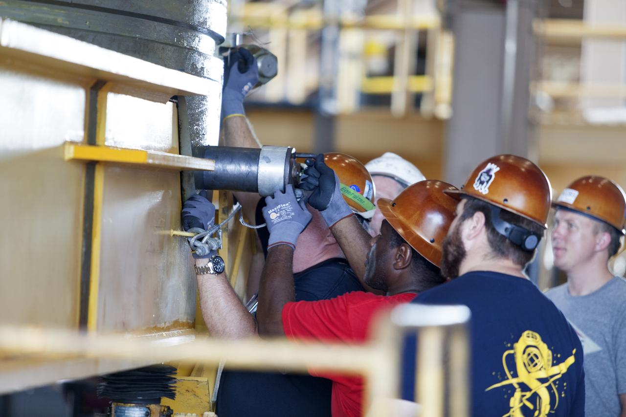
Jacobs technicians, on the Test and Operations Support Contract, check bolt fittings as they practice crane operations with an inert booster rocket segment in the Rotation, Processing and Surge Facility on June 22, 2018, at NASA's Kennedy Space Center in Florida. Dual cranes are being used to move the segment from vertical to horizontal, a maneuver known as a "breakover rotation." As part of routine processing operations for the agency's Space Launch System (SLS) rocket, the RPSF team will receive all of the solid rocket fuel segments for inspection and preparation prior to transporting them to the Vehicle Assembly Building for stacking on the mobile launcher. Many pathfinding operations are being done to prepare for launch of the SLS and Orion spacecraft on Exploration Mission-1 and deep space missions.
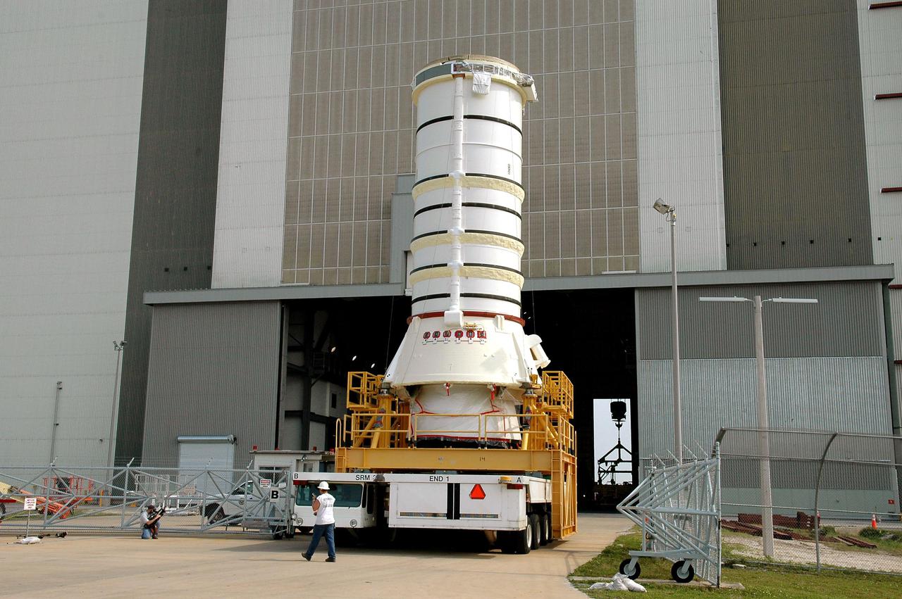
KENNEDY SPACE CENTER, FLA. - The aft segment of a Solid Rocket Booster rolls toward the opening in the Vehicle Assembly Building. The segment will be mated with other segments for use on the launch of Space Shuttle Atlantis on the second Return to Flight mission, STS-121. SRBs are used as matched pairs and each is made up of four solid rocket motor segments. Two SRBs provide the main thrust to lift the Space Shuttle off the pad to an altitude of about 150,000 feet. In addition, the two SRBs carry the entire weight of the External Tank and orbiter and transmit the weight load through their structure to the Mobile Launcher Platform. Each booster has a thrust (sea level) of approximately 3,300,000 pounds at launch, and provide 71.4 percent of the thrust at liftoff and during first-stage ascent.
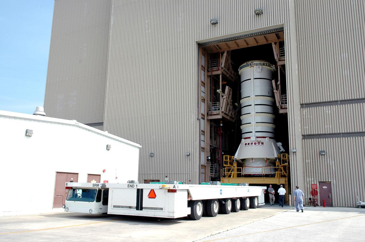
KENNEDY SPACE CENTER, FLA. - The aft segment of a Solid Rocket Booster (SRB) is ready to roll out of the Rotation Processing and Surge Facility at NASA’s Kennedy Space Center. The segment is being moved to the Vehicle Assembly Building where it will be mated with other segments for use on the launch of Space Shuttle Atlantis on the second Return to Flight mission, STS-121. SRBs are used as matched pairs and each is made up of four solid rocket motor segments. Two SRBs provide the main thrust to lift the Space Shuttle off the pad to an altitude of about 150,000 feet. In addition, the two SRBs carry the entire weight of the External Tank and orbiter and transmit the weight load through their structure to the Mobile Launcher Platform. Each booster has a thrust (sea level) of approximately 3,300,000 pounds at launch, and provide 71.4 percent of the thrust at liftoff and during first-stage ascent.
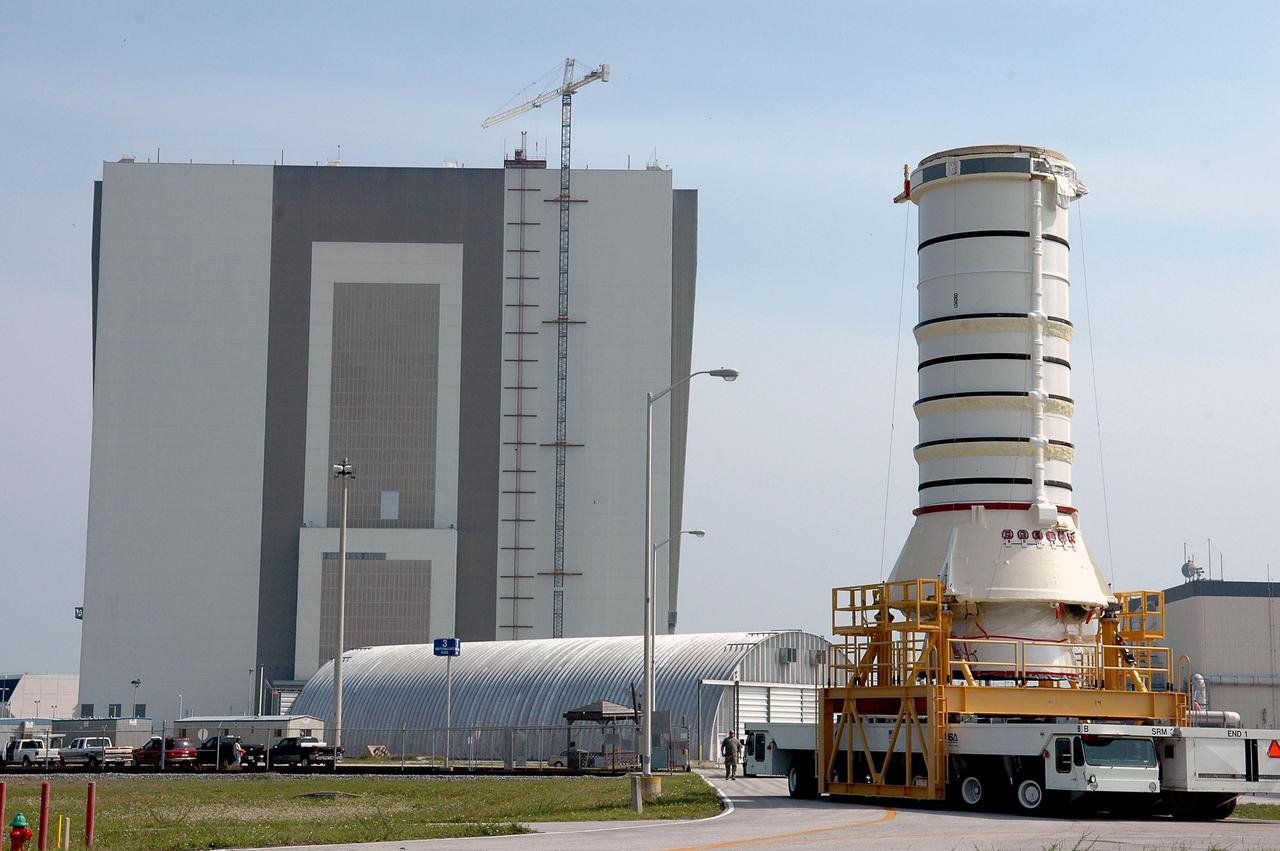
KENNEDY SPACE CENTER, FLA. - The aft segment of a Solid Rocket Booster is transported to the Vehicle Assembly Building (in the background). The segment will be mated with other segments for use on the launch of Space Shuttle Atlantis on the second Return to Flight mission, STS-121. SRBs are used as matched pairs and each is made up of four solid rocket motor segments. Two SRBs provide the main thrust to lift the Space Shuttle off the pad to an altitude of about 150,000 feet. In addition, the two SRBs carry the entire weight of the External Tank and orbiter and transmit the weight load through their structure to the Mobile Launcher Platform. Each booster has a thrust (sea level) of approximately 3,300,000 pounds at launch, and provide 71.4 percent of the thrust at liftoff and during first-stage ascent.
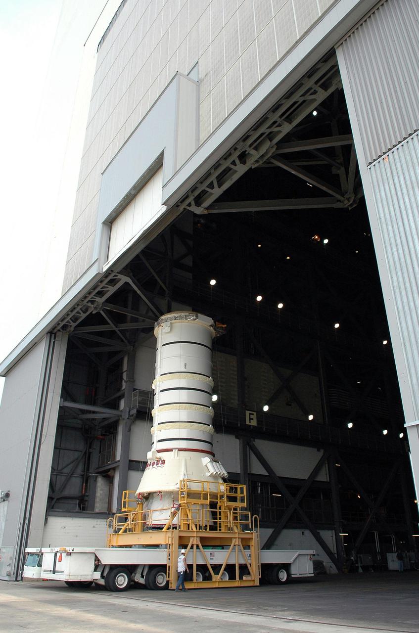
KENNEDY SPACE CENTER, FLA. - The aft segment of a Solid Rocket Booster rolls into the Vehicle Assembly Building. The segment will be mated with other segments for use on the launch of Space Shuttle Atlantis on the second Return to Flight mission, STS-121. SRBs are used as matched pairs and each is made up of four solid rocket motor segments. Two SRBs provide the main thrust to lift the Space Shuttle off the pad to an altitude of about 150,000 feet. In addition, the two SRBs carry the entire weight of the External Tank and orbiter and transmit the weight load through their structure to the Mobile Launcher Platform. Each booster has a thrust (sea level) of approximately 3,300,000 pounds at launch, and provide 71.4 percent of the thrust at liftoff and during first-stage ascent.
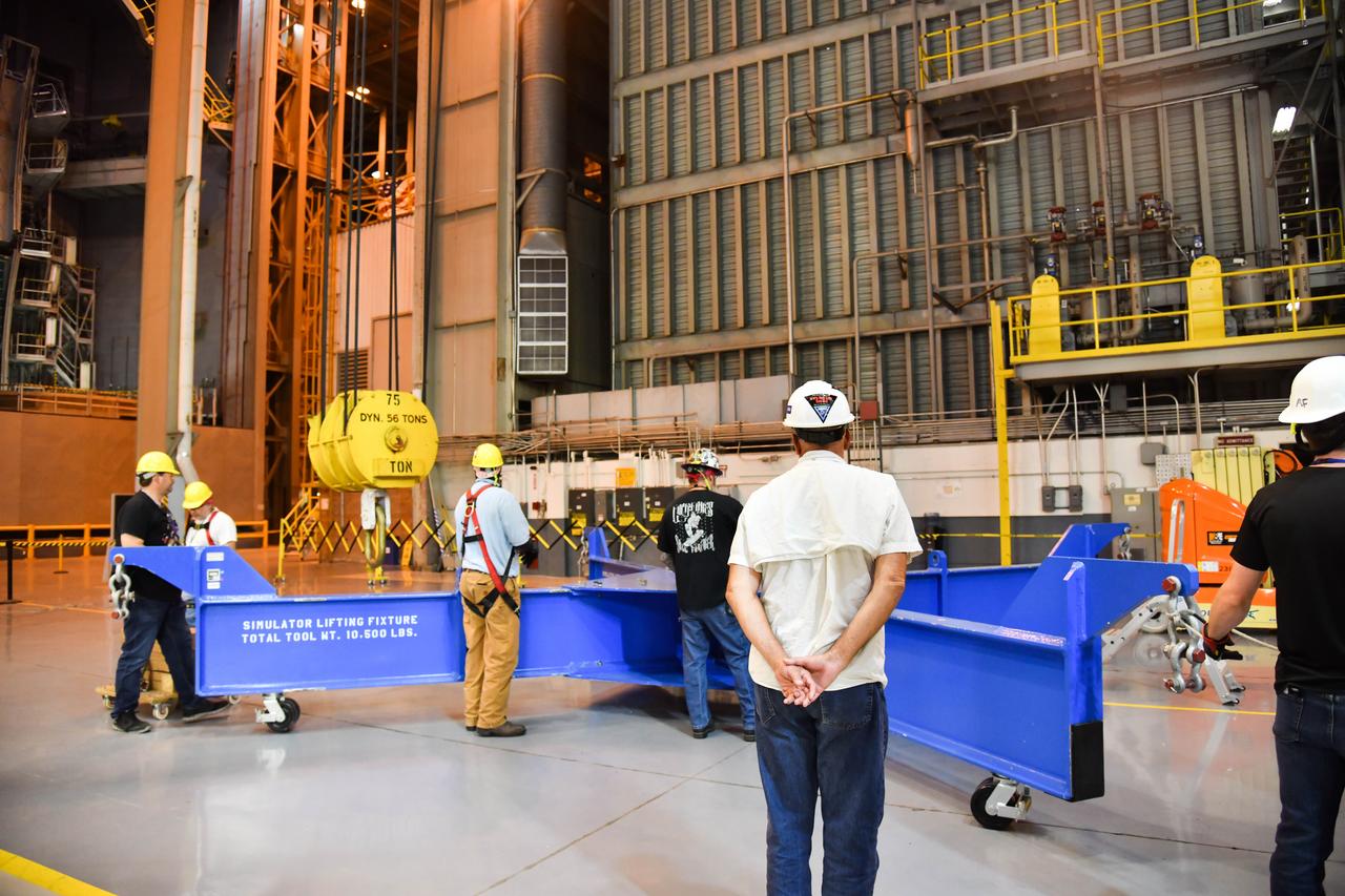
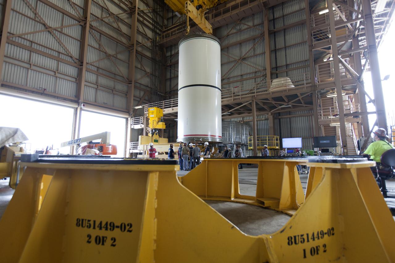
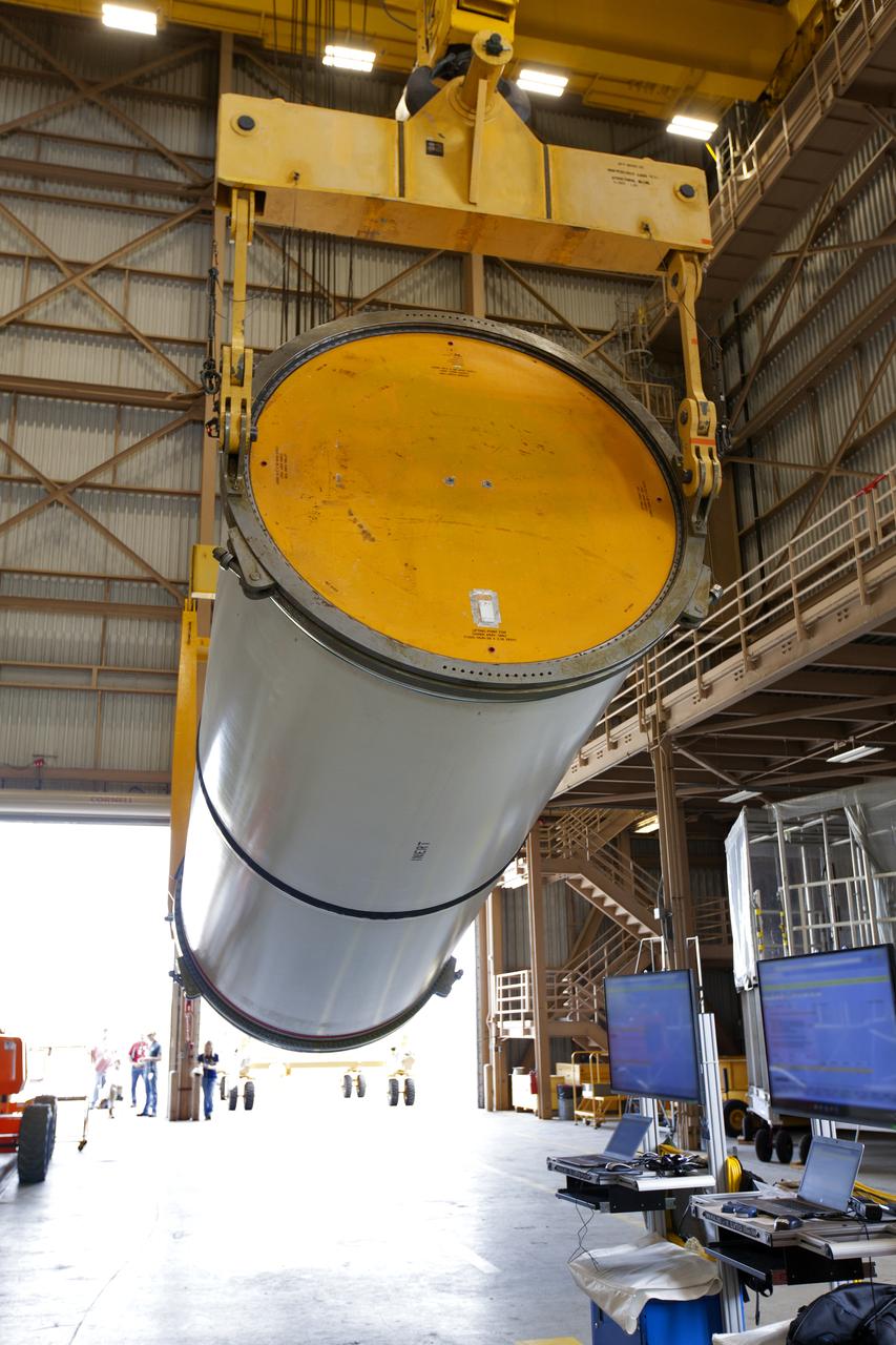
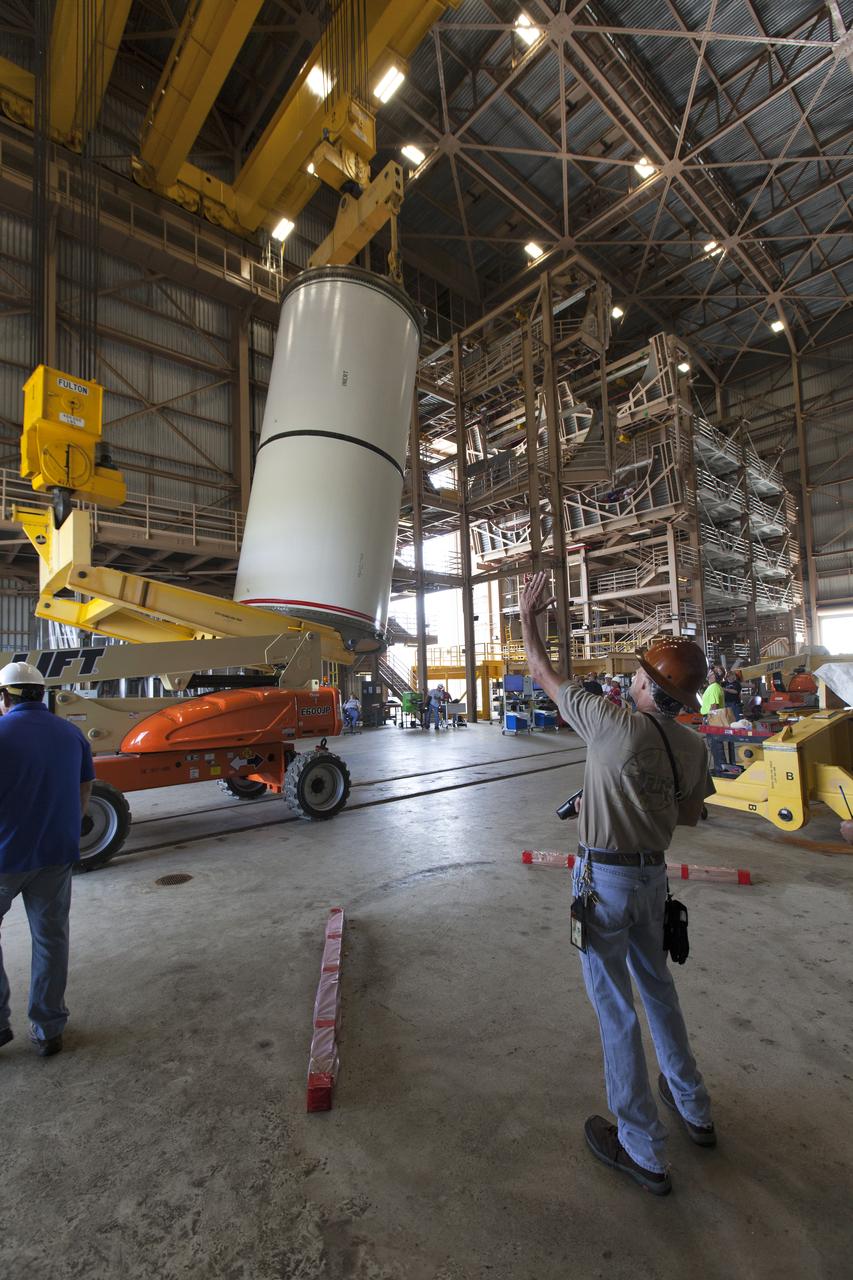
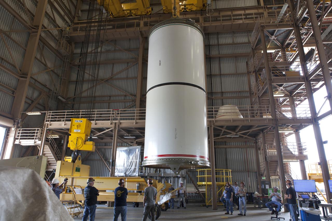
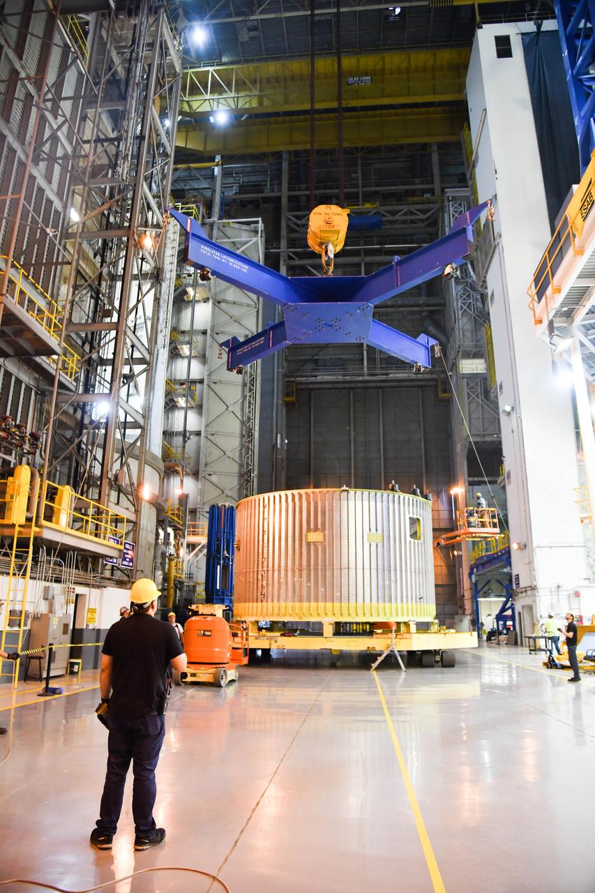
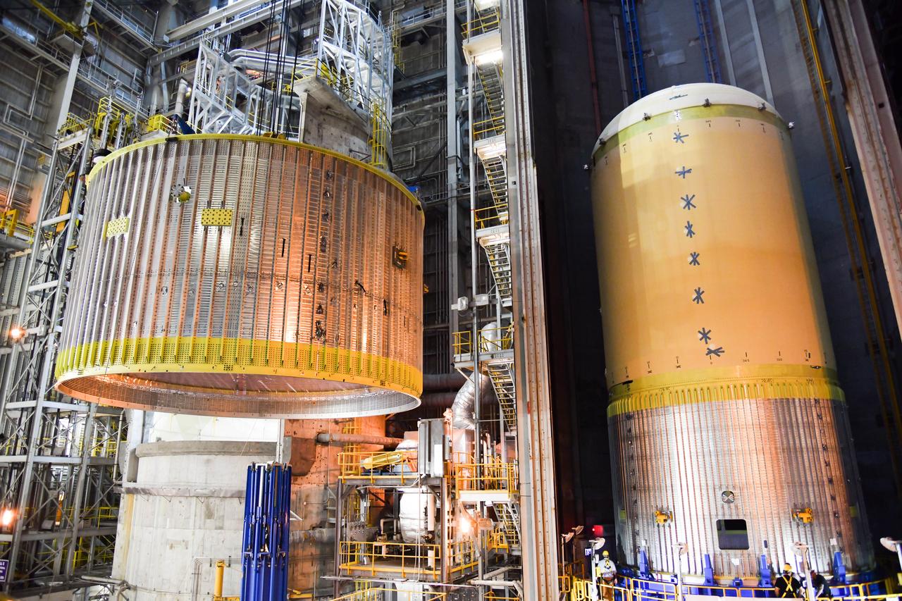
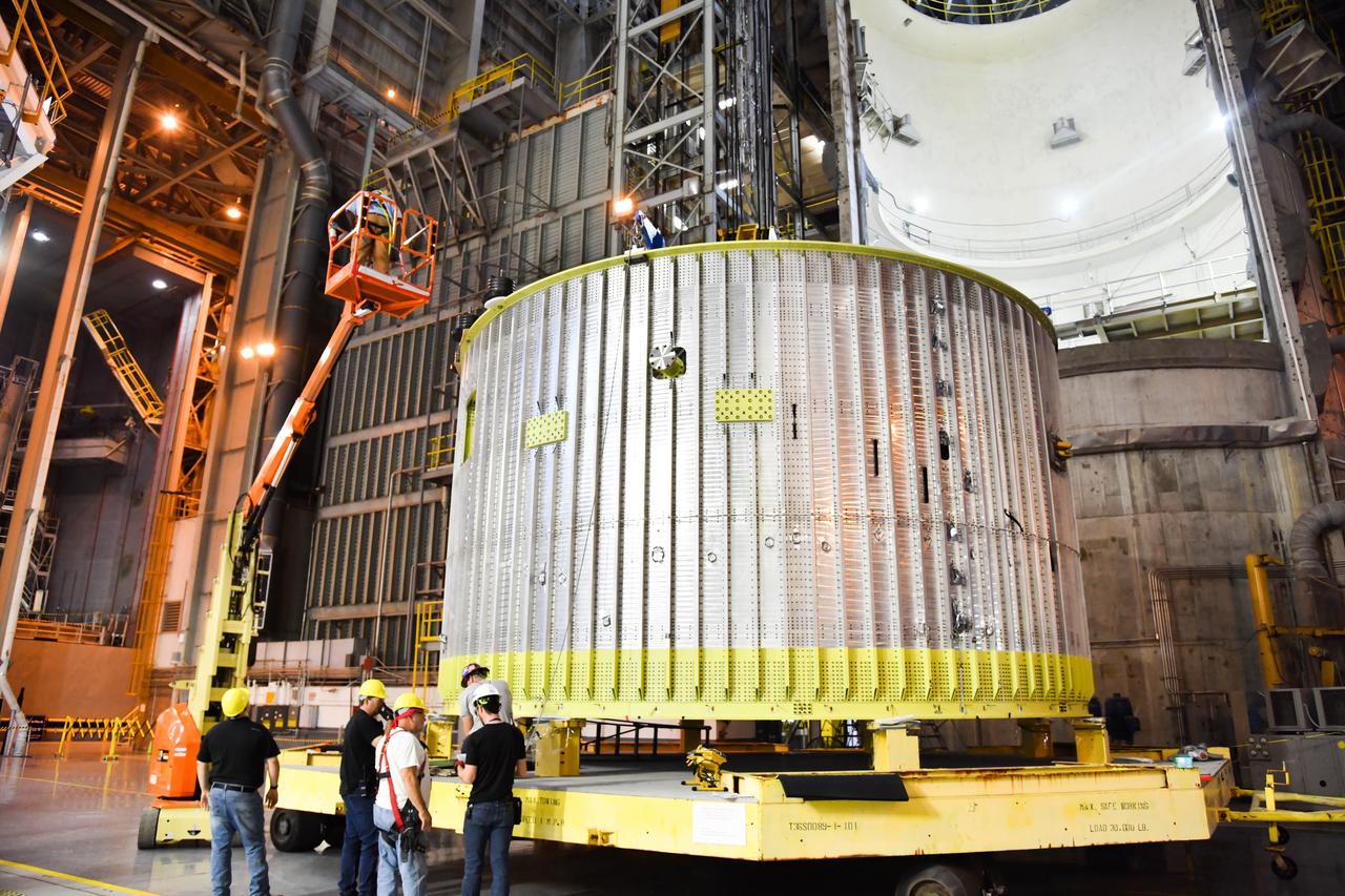
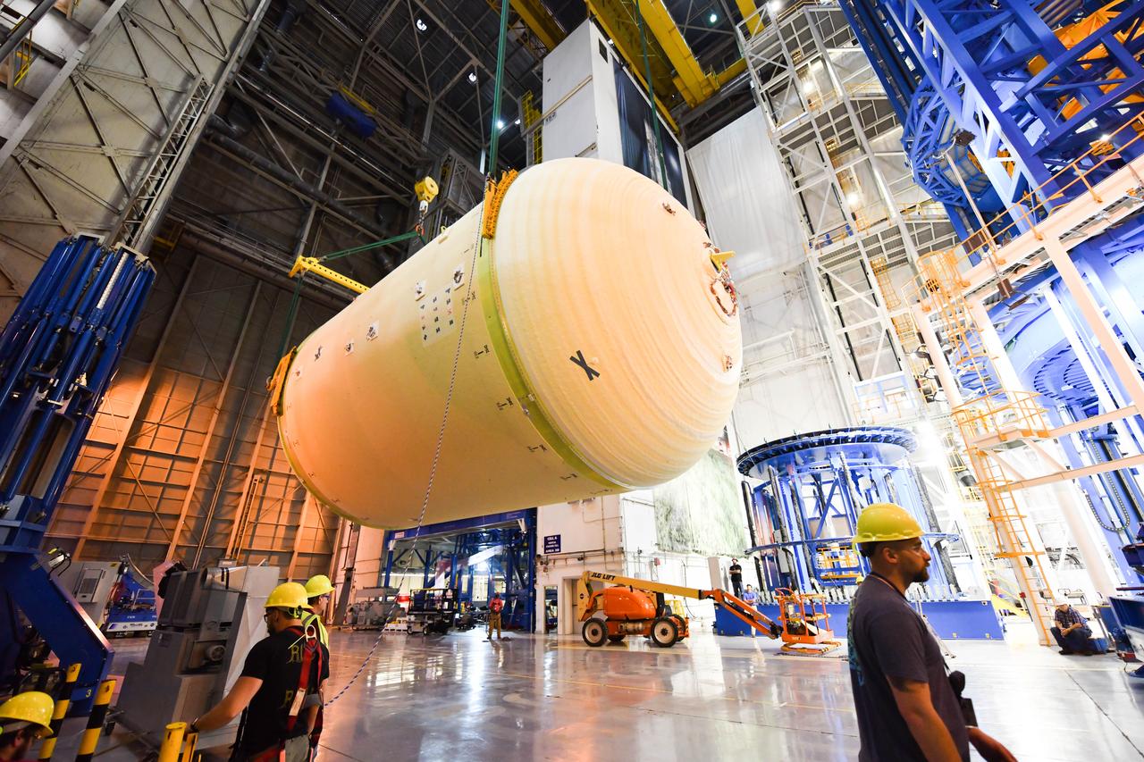
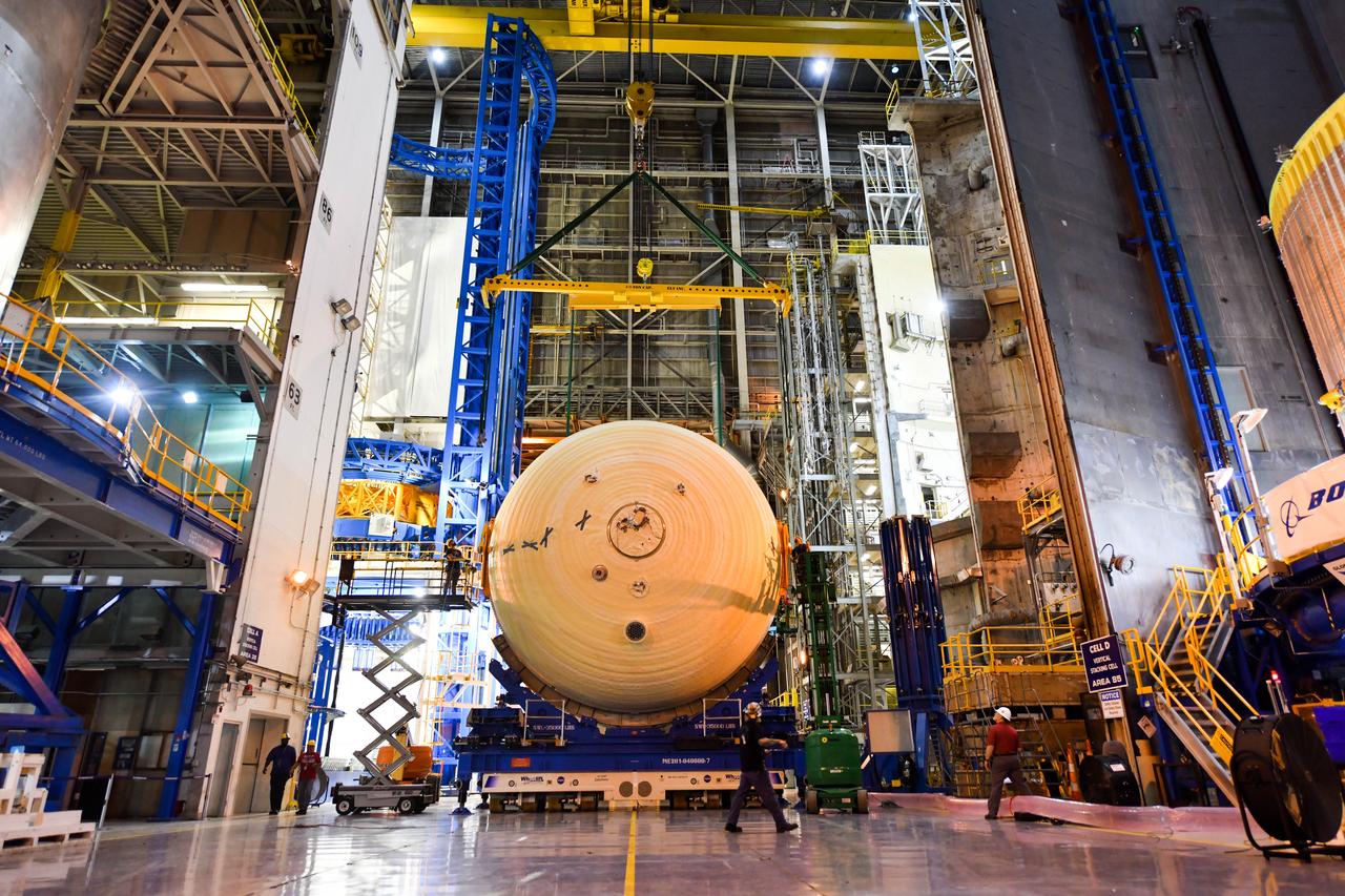
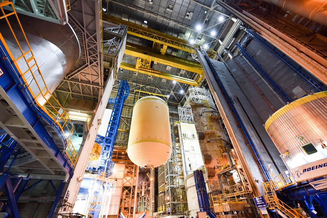
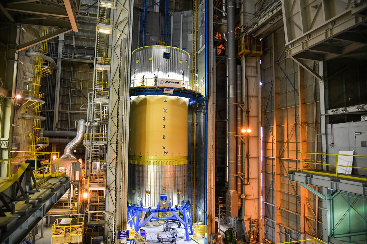
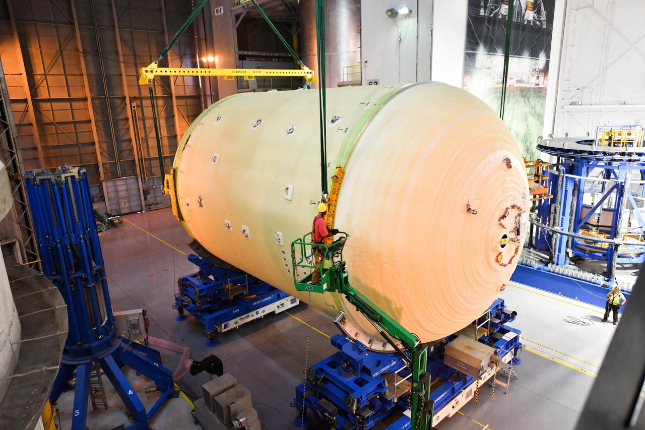
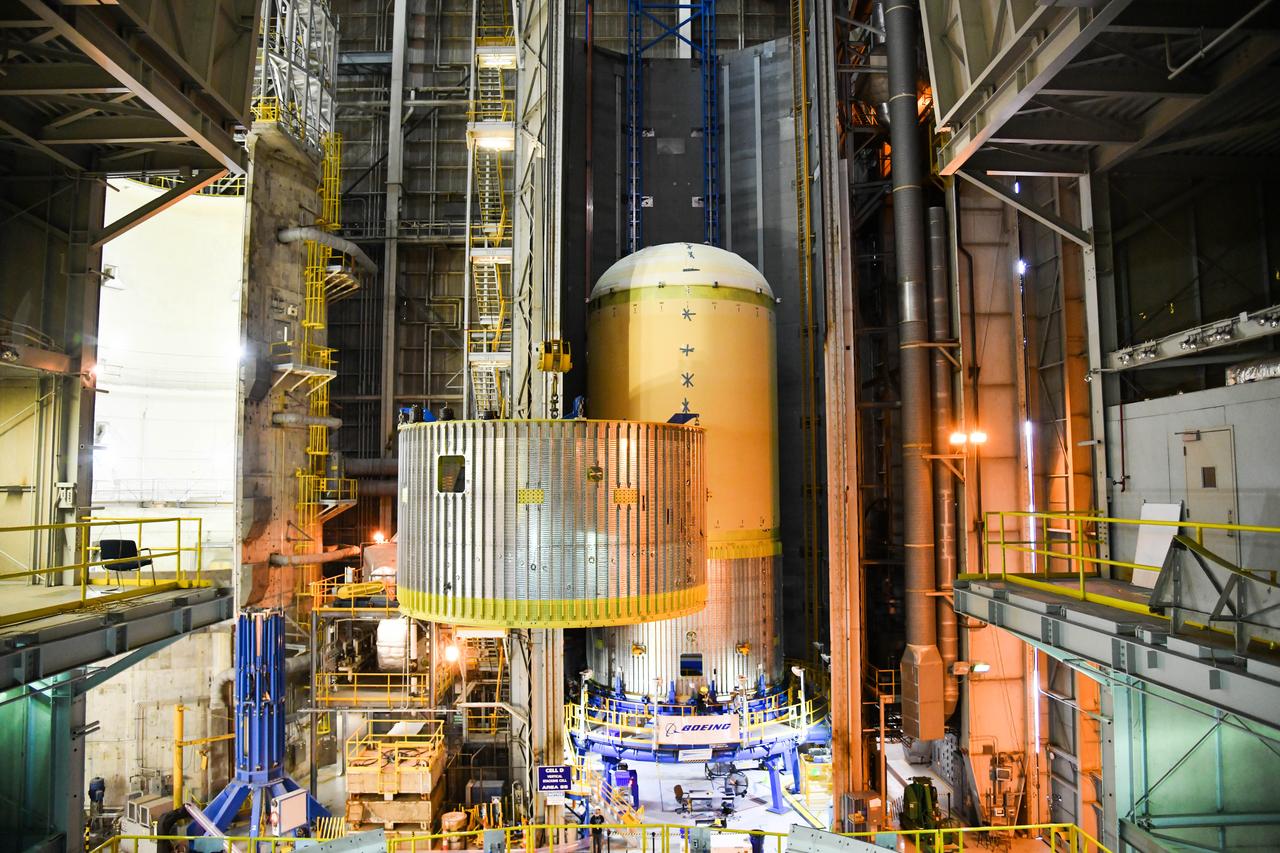
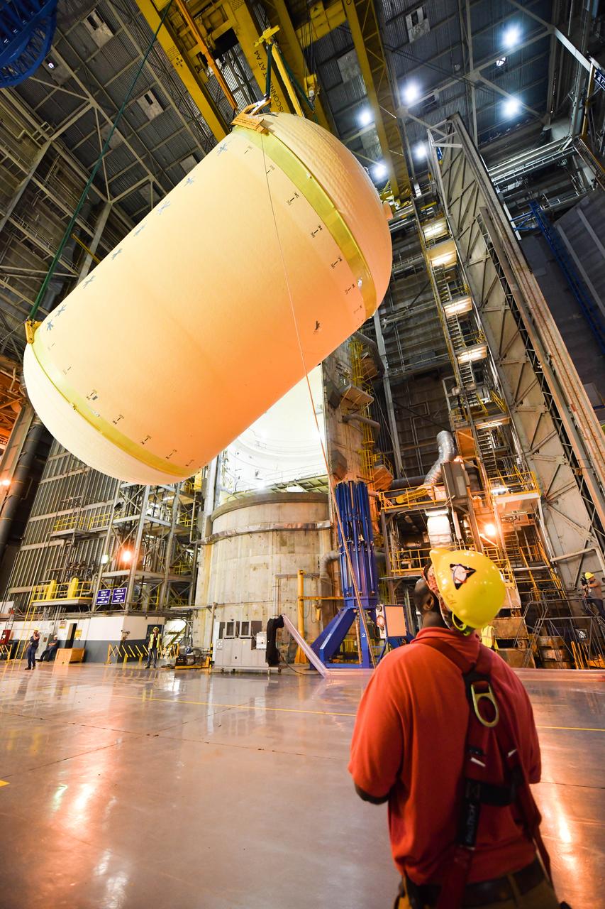
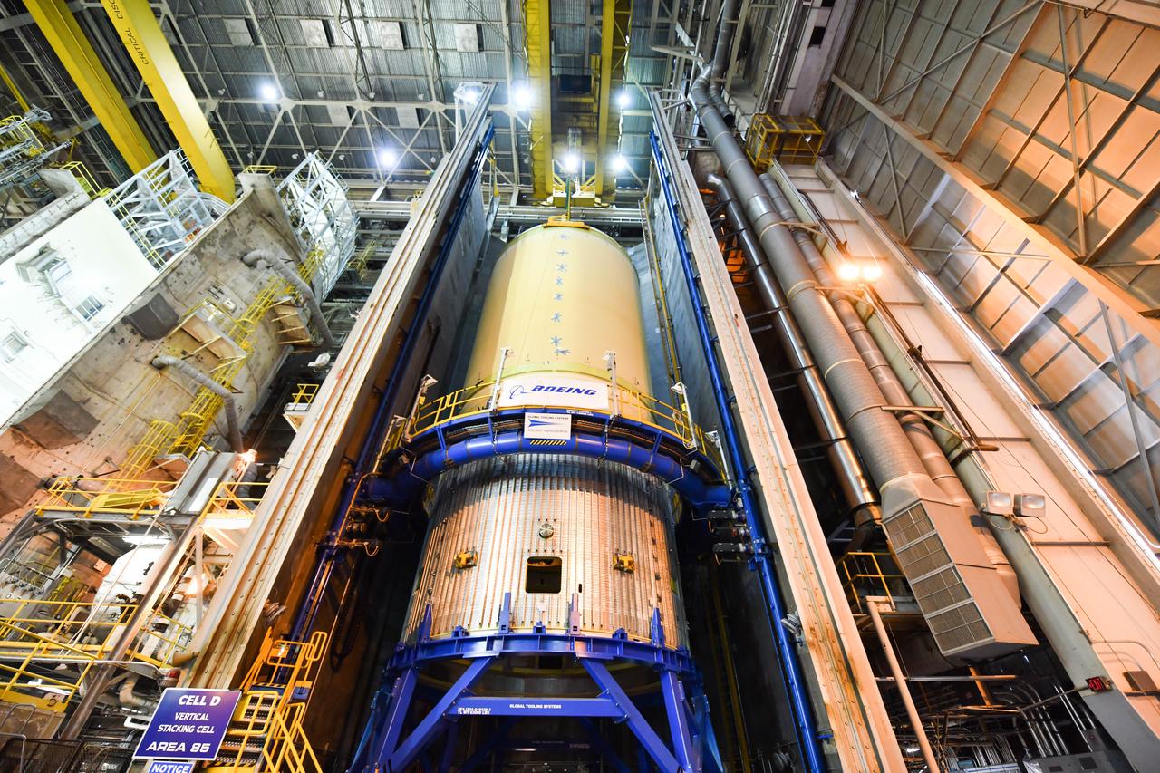
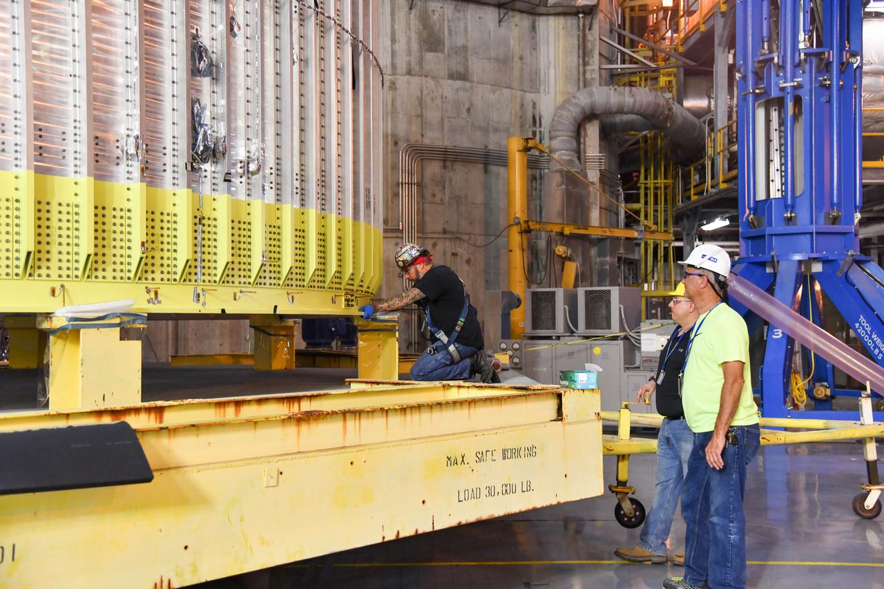
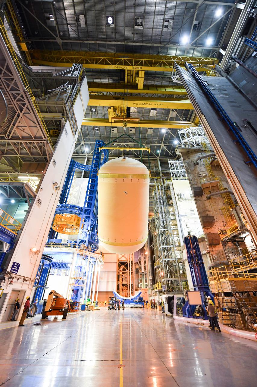
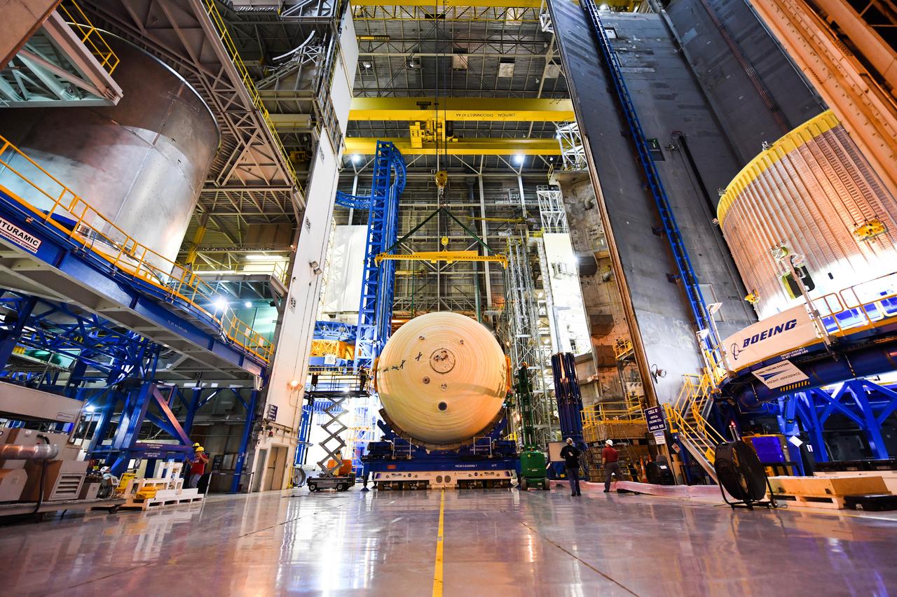
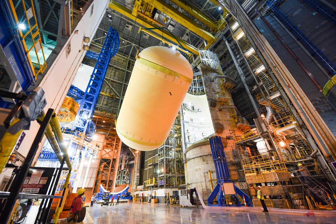
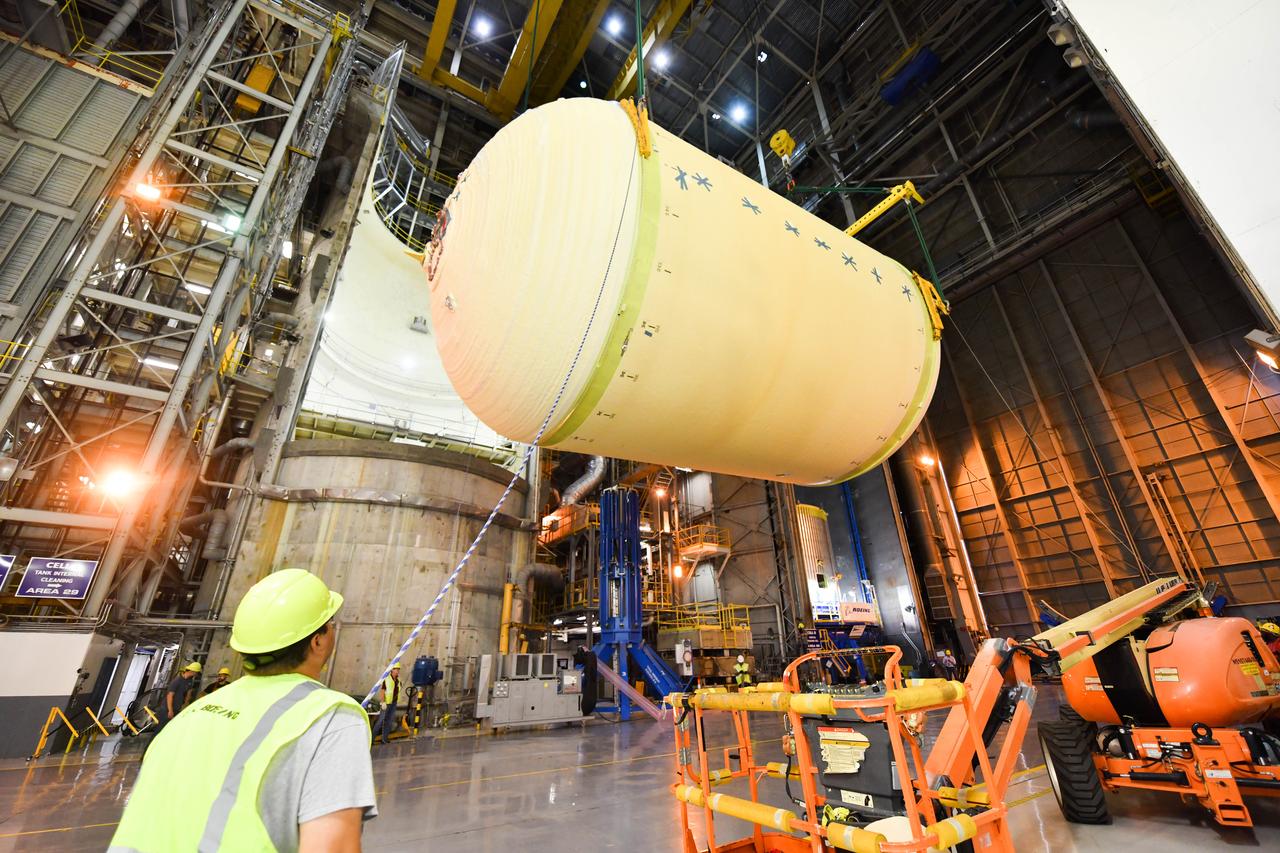
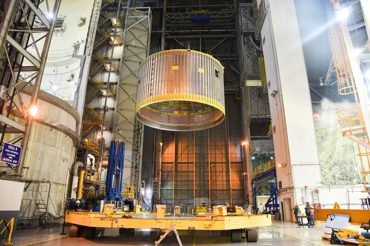
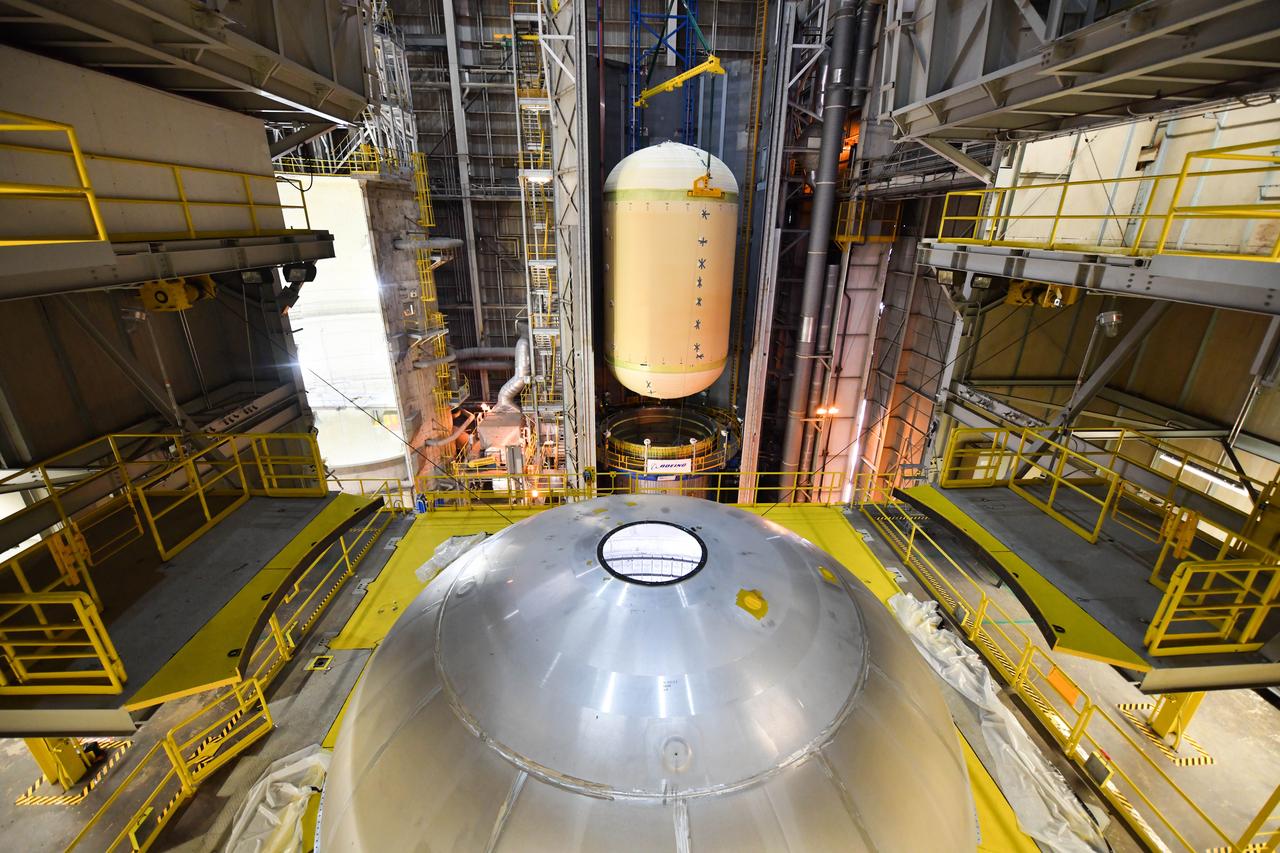
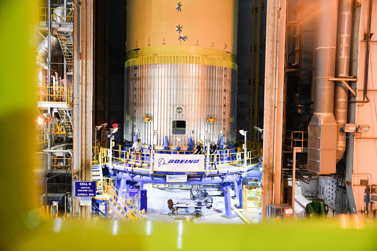
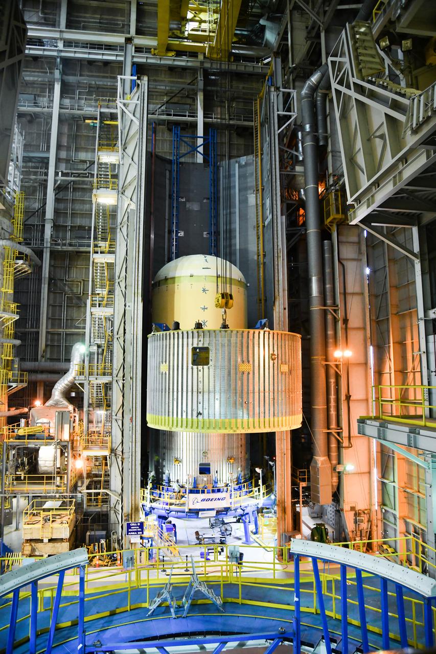
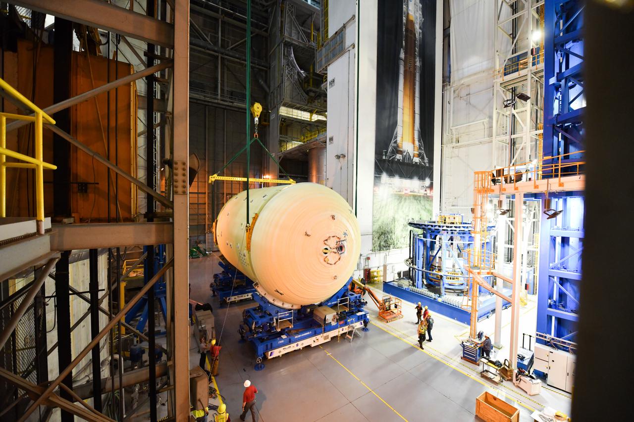
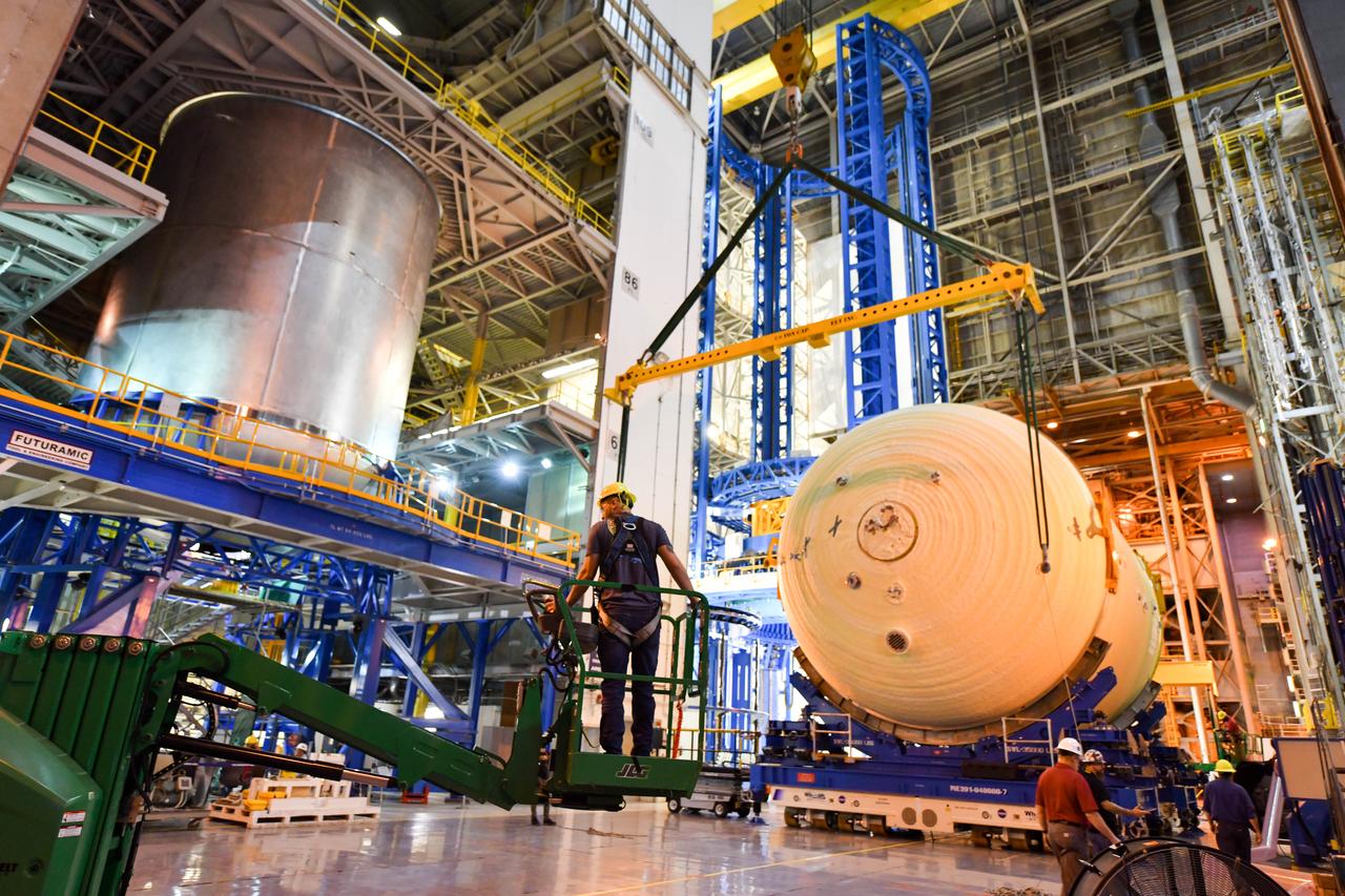
The Space Launch System (SLS) rocket’s liquid oxygen tank structural test article was manufactured and stacked in June 2019 at NASA’s Michoud Assembly Facility in New Orleans. To construct the test article, Boeing technicians at Michoud moved the liquid oxygen tank to the Vertical Assemby Building stacking and integration area. Here, they added simulators to mimic the two structures that connect to the tank, the intertank and the forward skirt. This structural hardware for the SLS core stage for America’s new deep space rocket is structurally identical to the flight version of the tank. It will be shipped on the Pegasus barge to NASA’s Marshall Space Flight Center in Hunstville, Alabama, where it will undergo a series of tests that simulate the stresses and loads of liftoff and flight. These tests will help ensure designs are adequate for successful SLS missions to the Moon and beyond. The flight liquid oxygen tank along with the liquid hydrogen tank supplies more than 500,000 gallons of propellant to the core stages four RS-25 engines, which produce 2 million pounds of thrust to help send the SLS rocket to space.
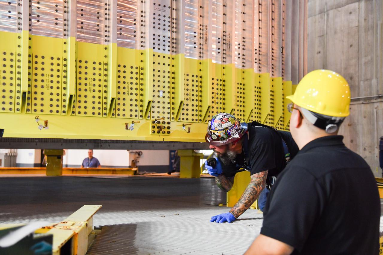
The Space Launch System (SLS) rocket’s liquid oxygen tank structural test article was manufactured and stacked in June 2019 at NASA’s Michoud Assembly Facility in New Orleans. To construct the test article, Boeing technicians at Michoud moved the liquid oxygen tank to the Vertical Assemby Building stacking and integration area. Here, they added simulators to mimic the two structures that connect to the tank, the intertank and the forward skirt. This structural hardware for the SLS core stage for America’s new deep space rocket is structurally identical to the flight version of the tank. It will be shipped on the Pegasus barge to NASA’s Marshall Space Flight Center in Hunstville, Alabama, where it will undergo a series of tests that simulate the stresses and loads of liftoff and flight. These tests will help ensure designs are adequate for successful SLS missions to the Moon and beyond. The flight liquid oxygen tank along with the liquid hydrogen tank supplies more than 500,000 gallons of propellant to the core stages four RS-25 engines, which produce 2 million pounds of thrust to help send the SLS rocket to space.
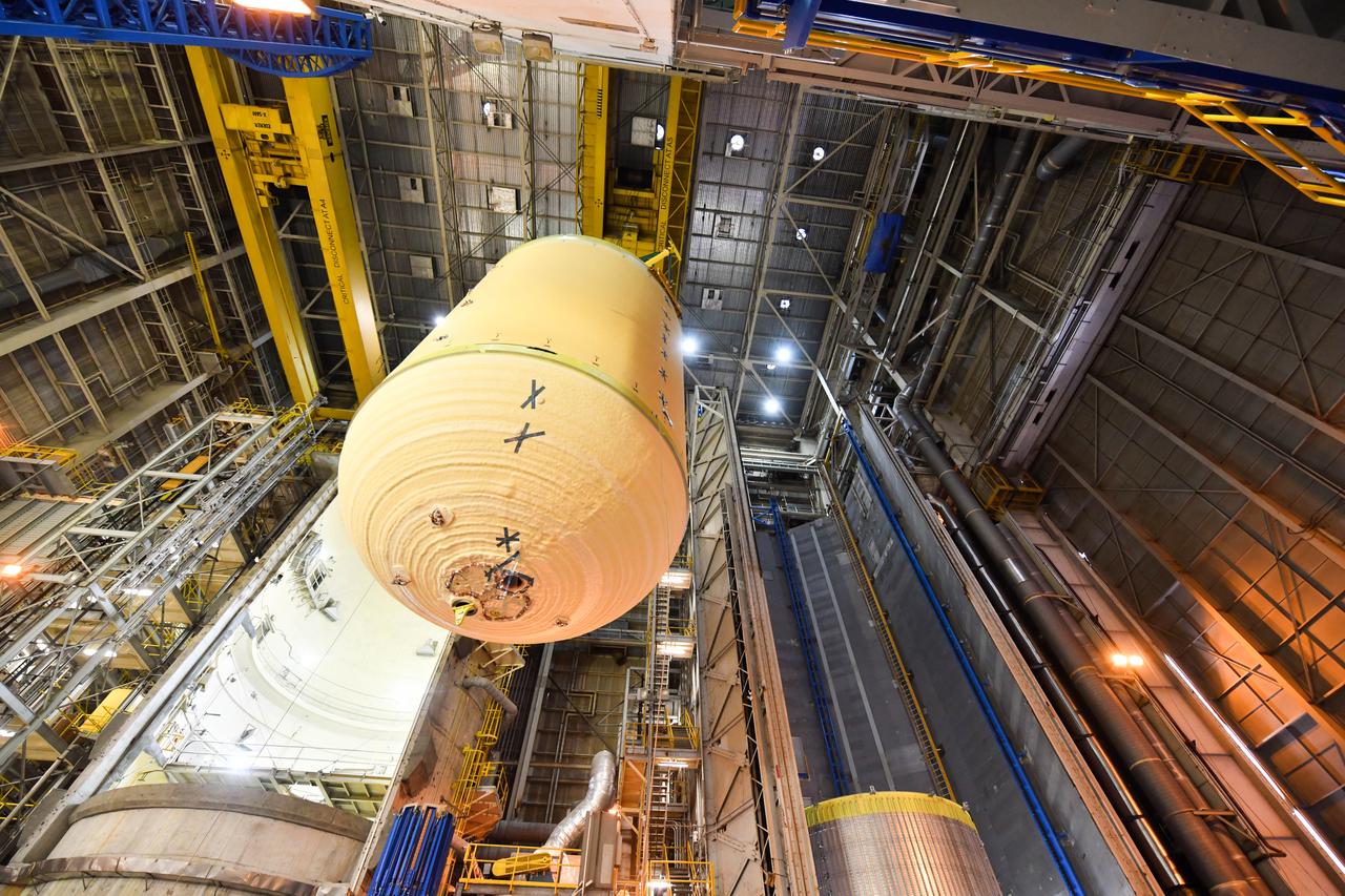
The Space Launch System (SLS) rocket’s liquid oxygen tank structural test article was manufactured and stacked in June 2019 at NASA’s Michoud Assembly Facility in New Orleans. To construct the test article, Boeing technicians at Michoud moved the liquid oxygen tank to the Vertical Assemby Building stacking and integration area. Here, they added simulators to mimic the two structures that connect to the tank, the intertank and the forward skirt. This structural hardware for the SLS core stage for America’s new deep space rocket is structurally identical to the flight version of the tank. It will be shipped on the Pegasus barge to NASA’s Marshall Space Flight Center in Hunstville, Alabama, where it will undergo a series of tests that simulate the stresses and loads of liftoff and flight. These tests will help ensure designs are adequate for successful SLS missions to the Moon and beyond. The flight liquid oxygen tank along with the liquid hydrogen tank supplies more than 500,000 gallons of propellant to the core stages four RS-25 engines, which produce 2 million pounds of thrust to help send the SLS rocket to space.
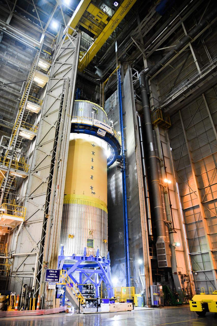
The Space Launch System (SLS) rocket’s liquid oxygen tank structural test article was manufactured and stacked in June 2019 at NASA’s Michoud Assembly Facility in New Orleans. To construct the test article, Boeing technicians at Michoud moved the liquid oxygen tank to the Vertical Assemby Building stacking and integration area. Here, they added simulators to mimic the two structures that connect to the tank, the intertank and the forward skirt. This structural hardware for the SLS core stage for America’s new deep space rocket is structurally identical to the flight version of the tank. It will be shipped on the Pegasus barge to NASA’s Marshall Space Flight Center in Hunstville, Alabama, where it will undergo a series of tests that simulate the stresses and loads of liftoff and flight. These tests will help ensure designs are adequate for successful SLS missions to the Moon and beyond. The flight liquid oxygen tank along with the liquid hydrogen tank supplies more than 500,000 gallons of propellant to the core stages four RS-25 engines, which produce 2 million pounds of thrust to help send the SLS rocket to space.
The Space Launch System (SLS) rocket’s liquid oxygen tank structural test article was manufactured and stacked in June 2019 at NASA’s Michoud Assembly Facility in New Orleans. To construct the test article, Boeing technicians at Michoud moved the liquid oxygen tank to the Vertical Assemby Building stacking and integration area. Here, they added simulators to mimic the two structures that connect to the tank, the intertank and the forward skirt. This structural hardware for the SLS core stage for America’s new deep space rocket is structurally identical to the flight version of the tank. It will be shipped on the Pegasus barge to NASA’s Marshall Space Flight Center in Hunstville, Alabama, where it will undergo a series of tests that simulate the stresses and loads of liftoff and flight. These tests will help ensure designs are adequate for successful SLS missions to the Moon and beyond. The flight liquid oxygen tank along with the liquid hydrogen tank supplies more than 500,000 gallons of propellant to the core stages four RS-25 engines, which produce 2 million pounds of thrust to help send the SLS rocket to space.
The Space Launch System (SLS) rocket’s liquid oxygen tank structural test article was manufactured and stacked in June 2019 at NASA’s Michoud Assembly Facility in New Orleans. To construct the test article, Boeing technicians at Michoud moved the liquid oxygen tank to the Vertical Assemby Building stacking and integration area. Here, they added simulators to mimic the two structures that connect to the tank, the intertank and the forward skirt. This structural hardware for the SLS core stage for America’s new deep space rocket is structurally identical to the flight version of the tank. It will be shipped on the Pegasus barge to NASA’s Marshall Space Flight Center in Hunstville, Alabama, where it will undergo a series of tests that simulate the stresses and loads of liftoff and flight. These tests will help ensure designs are adequate for successful SLS missions to the Moon and beyond. The flight liquid oxygen tank along with the liquid hydrogen tank supplies more than 500,000 gallons of propellant to the core stages four RS-25 engines, which produce 2 million pounds of thrust to help send the SLS rocket to space.
The Space Launch System (SLS) rocket’s liquid oxygen tank structural test article was manufactured and stacked in June 2019 at NASA’s Michoud Assembly Facility in New Orleans. To construct the test article, Boeing technicians at Michoud moved the liquid oxygen tank to the Vertical Assemby Building stacking and integration area. Here, they added simulators to mimic the two structures that connect to the tank, the intertank and the forward skirt. This structural hardware for the SLS core stage for America’s new deep space rocket is structurally identical to the flight version of the tank. It will be shipped on the Pegasus barge to NASA’s Marshall Space Flight Center in Hunstville, Alabama, where it will undergo a series of tests that simulate the stresses and loads of liftoff and flight. These tests will help ensure designs are adequate for successful SLS missions to the Moon and beyond. The flight liquid oxygen tank along with the liquid hydrogen tank supplies more than 500,000 gallons of propellant to the core stages four RS-25 engines, which produce 2 million pounds of thrust to help send the SLS rocket to space.
The Space Launch System (SLS) rocket’s liquid oxygen tank structural test article was manufactured and stacked in June 2019 at NASA’s Michoud Assembly Facility in New Orleans. To construct the test article, Boeing technicians at Michoud moved the liquid oxygen tank to the Vertical Assemby Building stacking and integration area. Here, they added simulators to mimic the two structures that connect to the tank, the intertank and the forward skirt. This structural hardware for the SLS core stage for America’s new deep space rocket is structurally identical to the flight version of the tank. It will be shipped on the Pegasus barge to NASA’s Marshall Space Flight Center in Hunstville, Alabama, where it will undergo a series of tests that simulate the stresses and loads of liftoff and flight. These tests will help ensure designs are adequate for successful SLS missions to the Moon and beyond. The flight liquid oxygen tank along with the liquid hydrogen tank supplies more than 500,000 gallons of propellant to the core stages four RS-25 engines, which produce 2 million pounds of thrust to help send the SLS rocket to space.
The Space Launch System (SLS) rocket’s liquid oxygen tank structural test article was manufactured and stacked in June 2019 at NASA’s Michoud Assembly Facility in New Orleans. To construct the test article, Boeing technicians at Michoud moved the liquid oxygen tank to the Vertical Assemby Building stacking and integration area. Here, they added simulators to mimic the two structures that connect to the tank, the intertank and the forward skirt. This structural hardware for the SLS core stage for America’s new deep space rocket is structurally identical to the flight version of the tank. It will be shipped on the Pegasus barge to NASA’s Marshall Space Flight Center in Hunstville, Alabama, where it will undergo a series of tests that simulate the stresses and loads of liftoff and flight. These tests will help ensure designs are adequate for successful SLS missions to the Moon and beyond. The flight liquid oxygen tank along with the liquid hydrogen tank supplies more than 500,000 gallons of propellant to the core stages four RS-25 engines, which produce 2 million pounds of thrust to help send the SLS rocket to space.
The Space Launch System (SLS) rocket’s liquid oxygen tank structural test article was manufactured and stacked in June 2019 at NASA’s Michoud Assembly Facility in New Orleans. To construct the test article, Boeing technicians at Michoud moved the liquid oxygen tank to the Vertical Assemby Building stacking and integration area. Here, they added simulators to mimic the two structures that connect to the tank, the intertank and the forward skirt. This structural hardware for the SLS core stage for America’s new deep space rocket is structurally identical to the flight version of the tank. It will be shipped on the Pegasus barge to NASA’s Marshall Space Flight Center in Hunstville, Alabama, where it will undergo a series of tests that simulate the stresses and loads of liftoff and flight. These tests will help ensure designs are adequate for successful SLS missions to the Moon and beyond. The flight liquid oxygen tank along with the liquid hydrogen tank supplies more than 500,000 gallons of propellant to the core stages four RS-25 engines, which produce 2 million pounds of thrust to help send the SLS rocket to space.
The Space Launch System (SLS) rocket’s liquid oxygen tank structural test article was manufactured and stacked in June 2019 at NASA’s Michoud Assembly Facility in New Orleans. To construct the test article, Boeing technicians at Michoud moved the liquid oxygen tank to the Vertical Assemby Building stacking and integration area. Here, they added simulators to mimic the two structures that connect to the tank, the intertank and the forward skirt. This structural hardware for the SLS core stage for America’s new deep space rocket is structurally identical to the flight version of the tank. It will be shipped on the Pegasus barge to NASA’s Marshall Space Flight Center in Hunstville, Alabama, where it will undergo a series of tests that simulate the stresses and loads of liftoff and flight. These tests will help ensure designs are adequate for successful SLS missions to the Moon and beyond. The flight liquid oxygen tank along with the liquid hydrogen tank supplies more than 500,000 gallons of propellant to the core stages four RS-25 engines, which produce 2 million pounds of thrust to help send the SLS rocket to space.
The Space Launch System (SLS) rocket’s liquid oxygen tank structural test article was manufactured and stacked in June 2019 at NASA’s Michoud Assembly Facility in New Orleans. To construct the test article, Boeing technicians at Michoud moved the liquid oxygen tank to the Vertical Assemby Building stacking and integration area. Here, they added simulators to mimic the two structures that connect to the tank, the intertank and the forward skirt. This structural hardware for the SLS core stage for America’s new deep space rocket is structurally identical to the flight version of the tank. It will be shipped on the Pegasus barge to NASA’s Marshall Space Flight Center in Hunstville, Alabama, where it will undergo a series of tests that simulate the stresses and loads of liftoff and flight. These tests will help ensure designs are adequate for successful SLS missions to the Moon and beyond. The flight liquid oxygen tank along with the liquid hydrogen tank supplies more than 500,000 gallons of propellant to the core stages four RS-25 engines, which produce 2 million pounds of thrust to help send the SLS rocket to space.
The Space Launch System (SLS) rocket’s liquid oxygen tank structural test article was manufactured and stacked in June 2019 at NASA’s Michoud Assembly Facility in New Orleans. To construct the test article, Boeing technicians at Michoud moved the liquid oxygen tank to the Vertical Assemby Building stacking and integration area. Here, they added simulators to mimic the two structures that connect to the tank, the intertank and the forward skirt. This structural hardware for the SLS core stage for America’s new deep space rocket is structurally identical to the flight version of the tank. It will be shipped on the Pegasus barge to NASA’s Marshall Space Flight Center in Hunstville, Alabama, where it will undergo a series of tests that simulate the stresses and loads of liftoff and flight. These tests will help ensure designs are adequate for successful SLS missions to the Moon and beyond. The flight liquid oxygen tank along with the liquid hydrogen tank supplies more than 500,000 gallons of propellant to the core stages four RS-25 engines, which produce 2 million pounds of thrust to help send the SLS rocket to space.
The Space Launch System (SLS) rocket’s liquid oxygen tank structural test article was manufactured and stacked in June 2019 at NASA’s Michoud Assembly Facility in New Orleans. To construct the test article, Boeing technicians at Michoud moved the liquid oxygen tank to the Vertical Assemby Building stacking and integration area. Here, they added simulators to mimic the two structures that connect to the tank, the intertank and the forward skirt. This structural hardware for the SLS core stage for America’s new deep space rocket is structurally identical to the flight version of the tank. It will be shipped on the Pegasus barge to NASA’s Marshall Space Flight Center in Hunstville, Alabama, where it will undergo a series of tests that simulate the stresses and loads of liftoff and flight. These tests will help ensure designs are adequate for successful SLS missions to the Moon and beyond. The flight liquid oxygen tank along with the liquid hydrogen tank supplies more than 500,000 gallons of propellant to the core stages four RS-25 engines, which produce 2 million pounds of thrust to help send the SLS rocket to space.
The Space Launch System (SLS) rocket’s liquid oxygen tank structural test article was manufactured and stacked in June 2019 at NASA’s Michoud Assembly Facility in New Orleans. To construct the test article, Boeing technicians at Michoud moved the liquid oxygen tank to the Vertical Assemby Building stacking and integration area. Here, they added simulators to mimic the two structures that connect to the tank, the intertank and the forward skirt. This structural hardware for the SLS core stage for America’s new deep space rocket is structurally identical to the flight version of the tank. It will be shipped on the Pegasus barge to NASA’s Marshall Space Flight Center in Hunstville, Alabama, where it will undergo a series of tests that simulate the stresses and loads of liftoff and flight. These tests will help ensure designs are adequate for successful SLS missions to the Moon and beyond. The flight liquid oxygen tank along with the liquid hydrogen tank supplies more than 500,000 gallons of propellant to the core stages four RS-25 engines, which produce 2 million pounds of thrust to help send the SLS rocket to space.
The Space Launch System (SLS) rocket’s liquid oxygen tank structural test article was manufactured and stacked in June 2019 at NASA’s Michoud Assembly Facility in New Orleans. To construct the test article, Boeing technicians at Michoud moved the liquid oxygen tank to the Vertical Assemby Building stacking and integration area. Here, they added simulators to mimic the two structures that connect to the tank, the intertank and the forward skirt. This structural hardware for the SLS core stage for America’s new deep space rocket is structurally identical to the flight version of the tank. It will be shipped on the Pegasus barge to NASA’s Marshall Space Flight Center in Hunstville, Alabama, where it will undergo a series of tests that simulate the stresses and loads of liftoff and flight. These tests will help ensure designs are adequate for successful SLS missions to the Moon and beyond. The flight liquid oxygen tank along with the liquid hydrogen tank supplies more than 500,000 gallons of propellant to the core stages four RS-25 engines, which produce 2 million pounds of thrust to help send the SLS rocket to space.
The Space Launch System (SLS) rocket’s liquid oxygen tank structural test article was manufactured and stacked in June 2019 at NASA’s Michoud Assembly Facility in New Orleans. To construct the test article, Boeing technicians at Michoud moved the liquid oxygen tank to the Vertical Assemby Building stacking and integration area. Here, they added simulators to mimic the two structures that connect to the tank, the intertank and the forward skirt. This structural hardware for the SLS core stage for America’s new deep space rocket is structurally identical to the flight version of the tank. It will be shipped on the Pegasus barge to NASA’s Marshall Space Flight Center in Hunstville, Alabama, where it will undergo a series of tests that simulate the stresses and loads of liftoff and flight. These tests will help ensure designs are adequate for successful SLS missions to the Moon and beyond. The flight liquid oxygen tank along with the liquid hydrogen tank supplies more than 500,000 gallons of propellant to the core stages four RS-25 engines, which produce 2 million pounds of thrust to help send the SLS rocket to space.
The Space Launch System (SLS) rocket’s liquid oxygen tank structural test article was manufactured and stacked in June 2019 at NASA’s Michoud Assembly Facility in New Orleans. To construct the test article, Boeing technicians at Michoud moved the liquid oxygen tank to the Vertical Assemby Building stacking and integration area. Here, they added simulators to mimic the two structures that connect to the tank, the intertank and the forward skirt. This structural hardware for the SLS core stage for America’s new deep space rocket is structurally identical to the flight version of the tank. It will be shipped on the Pegasus barge to NASA’s Marshall Space Flight Center in Hunstville, Alabama, where it will undergo a series of tests that simulate the stresses and loads of liftoff and flight. These tests will help ensure designs are adequate for successful SLS missions to the Moon and beyond. The flight liquid oxygen tank along with the liquid hydrogen tank supplies more than 500,000 gallons of propellant to the core stages four RS-25 engines, which produce 2 million pounds of thrust to help send the SLS rocket to space.
The Space Launch System (SLS) rocket’s liquid oxygen tank structural test article was manufactured and stacked in June 2019 at NASA’s Michoud Assembly Facility in New Orleans. To construct the test article, Boeing technicians at Michoud moved the liquid oxygen tank to the Vertical Assemby Building stacking and integration area. Here, they added simulators to mimic the two structures that connect to the tank, the intertank and the forward skirt. This structural hardware for the SLS core stage for America’s new deep space rocket is structurally identical to the flight version of the tank. It will be shipped on the Pegasus barge to NASA’s Marshall Space Flight Center in Hunstville, Alabama, where it will undergo a series of tests that simulate the stresses and loads of liftoff and flight. These tests will help ensure designs are adequate for successful SLS missions to the Moon and beyond. The flight liquid oxygen tank along with the liquid hydrogen tank supplies more than 500,000 gallons of propellant to the core stages four RS-25 engines, which produce 2 million pounds of thrust to help send the SLS rocket to space.
The Space Launch System (SLS) rocket’s liquid oxygen tank structural test article was manufactured and stacked in June 2019 at NASA’s Michoud Assembly Facility in New Orleans. To construct the test article, Boeing technicians at Michoud moved the liquid oxygen tank to the Vertical Assemby Building stacking and integration area. Here, they added simulators to mimic the two structures that connect to the tank, the intertank and the forward skirt. This structural hardware for the SLS core stage for America’s new deep space rocket is structurally identical to the flight version of the tank. It will be shipped on the Pegasus barge to NASA’s Marshall Space Flight Center in Hunstville, Alabama, where it will undergo a series of tests that simulate the stresses and loads of liftoff and flight. These tests will help ensure designs are adequate for successful SLS missions to the Moon and beyond. The flight liquid oxygen tank along with the liquid hydrogen tank supplies more than 500,000 gallons of propellant to the core stages four RS-25 engines, which produce 2 million pounds of thrust to help send the SLS rocket to space.
The Space Launch System (SLS) rocket’s liquid oxygen tank structural test article was manufactured and stacked in June 2019 at NASA’s Michoud Assembly Facility in New Orleans. To construct the test article, Boeing technicians at Michoud moved the liquid oxygen tank to the Vertical Assemby Building stacking and integration area. Here, they added simulators to mimic the two structures that connect to the tank, the intertank and the forward skirt. This structural hardware for the SLS core stage for America’s new deep space rocket is structurally identical to the flight version of the tank. It will be shipped on the Pegasus barge to NASA’s Marshall Space Flight Center in Hunstville, Alabama, where it will undergo a series of tests that simulate the stresses and loads of liftoff and flight. These tests will help ensure designs are adequate for successful SLS missions to the Moon and beyond. The flight liquid oxygen tank along with the liquid hydrogen tank supplies more than 500,000 gallons of propellant to the core stages four RS-25 engines, which produce 2 million pounds of thrust to help send the SLS rocket to space.
The Space Launch System (SLS) rocket’s liquid oxygen tank structural test article was manufactured and stacked in June 2019 at NASA’s Michoud Assembly Facility in New Orleans. To construct the test article, Boeing technicians at Michoud moved the liquid oxygen tank to the Vertical Assemby Building stacking and integration area. Here, they added simulators to mimic the two structures that connect to the tank, the intertank and the forward skirt. This structural hardware for the SLS core stage for America’s new deep space rocket is structurally identical to the flight version of the tank. It will be shipped on the Pegasus barge to NASA’s Marshall Space Flight Center in Hunstville, Alabama, where it will undergo a series of tests that simulate the stresses and loads of liftoff and flight. These tests will help ensure designs are adequate for successful SLS missions to the Moon and beyond. The flight liquid oxygen tank along with the liquid hydrogen tank supplies more than 500,000 gallons of propellant to the core stages four RS-25 engines, which produce 2 million pounds of thrust to help send the SLS rocket to space.
The Space Launch System (SLS) rocket’s liquid oxygen tank structural test article was manufactured and stacked in June 2019 at NASA’s Michoud Assembly Facility in New Orleans. To construct the test article, Boeing technicians at Michoud moved the liquid oxygen tank to the Vertical Assemby Building stacking and integration area. Here, they added simulators to mimic the two structures that connect to the tank, the intertank and the forward skirt. This structural hardware for the SLS core stage for America’s new deep space rocket is structurally identical to the flight version of the tank. It will be shipped on the Pegasus barge to NASA’s Marshall Space Flight Center in Hunstville, Alabama, where it will undergo a series of tests that simulate the stresses and loads of liftoff and flight. These tests will help ensure designs are adequate for successful SLS missions to the Moon and beyond. The flight liquid oxygen tank along with the liquid hydrogen tank supplies more than 500,000 gallons of propellant to the core stages four RS-25 engines, which produce 2 million pounds of thrust to help send the SLS rocket to space.
The Space Launch System (SLS) rocket’s liquid oxygen tank structural test article was manufactured and stacked in June 2019 at NASA’s Michoud Assembly Facility in New Orleans. To construct the test article, Boeing technicians at Michoud moved the liquid oxygen tank to the Vertical Assemby Building stacking and integration area. Here, they added simulators to mimic the two structures that connect to the tank, the intertank and the forward skirt. This structural hardware for the SLS core stage for America’s new deep space rocket is structurally identical to the flight version of the tank. It will be shipped on the Pegasus barge to NASA’s Marshall Space Flight Center in Hunstville, Alabama, where it will undergo a series of tests that simulate the stresses and loads of liftoff and flight. These tests will help ensure designs are adequate for successful SLS missions to the Moon and beyond. The flight liquid oxygen tank along with the liquid hydrogen tank supplies more than 500,000 gallons of propellant to the core stages four RS-25 engines, which produce 2 million pounds of thrust to help send the SLS rocket to space.
The Space Launch System (SLS) rocket’s liquid oxygen tank structural test article was manufactured and stacked in June 2019 at NASA’s Michoud Assembly Facility in New Orleans. To construct the test article, Boeing technicians at Michoud moved the liquid oxygen tank to the Vertical Assemby Building stacking and integration area. Here, they added simulators to mimic the two structures that connect to the tank, the intertank and the forward skirt. This structural hardware for the SLS core stage for America’s new deep space rocket is structurally identical to the flight version of the tank. It will be shipped on the Pegasus barge to NASA’s Marshall Space Flight Center in Hunstville, Alabama, where it will undergo a series of tests that simulate the stresses and loads of liftoff and flight. These tests will help ensure designs are adequate for successful SLS missions to the Moon and beyond. The flight liquid oxygen tank along with the liquid hydrogen tank supplies more than 500,000 gallons of propellant to the core stages four RS-25 engines, which produce 2 million pounds of thrust to help send the SLS rocket to space.

The Space Launch System (SLS) rocket’s liquid oxygen tank structural test article was manufactured and stacked in June 2019 at NASA’s Michoud Assembly Facility in New Orleans. To construct the test article, Boeing technicians at Michoud moved the liquid oxygen tank to the Vertical Assemby Building stacking and integration area. Here, they added simulators to mimic the two structures that connect to the tank, the intertank and the forward skirt. This structural hardware for the SLS core stage for America’s new deep space rocket is structurally identical to the flight version of the tank. It will be shipped on the Pegasus barge to NASA’s Marshall Space Flight Center in Hunstville, Alabama, where it will undergo a series of tests that simulate the stresses and loads of liftoff and flight. These tests will help ensure designs are adequate for successful SLS missions to the Moon and beyond. The flight liquid oxygen tank along with the liquid hydrogen tank supplies more than 500,000 gallons of propellant to the core stages four RS-25 engines, which produce 2 million pounds of thrust to help send the SLS rocket to space.
The Space Launch System (SLS) rocket’s liquid oxygen tank structural test article was manufactured and stacked in June 2019 at NASA’s Michoud Assembly Facility in New Orleans. To construct the test article, Boeing technicians at Michoud moved the liquid oxygen tank to the Vertical Assemby Building stacking and integration area. Here, they added simulators to mimic the two structures that connect to the tank, the intertank and the forward skirt. This structural hardware for the SLS core stage for America’s new deep space rocket is structurally identical to the flight version of the tank. It will be shipped on the Pegasus barge to NASA’s Marshall Space Flight Center in Hunstville, Alabama, where it will undergo a series of tests that simulate the stresses and loads of liftoff and flight. These tests will help ensure designs are adequate for successful SLS missions to the Moon and beyond. The flight liquid oxygen tank along with the liquid hydrogen tank supplies more than 500,000 gallons of propellant to the core stages four RS-25 engines, which produce 2 million pounds of thrust to help send the SLS rocket to space.
The Space Launch System (SLS) rocket’s liquid oxygen tank structural test article was manufactured and stacked in June 2019 at NASA’s Michoud Assembly Facility in New Orleans. To construct the test article, Boeing technicians at Michoud moved the liquid oxygen tank to the Vertical Assemby Building stacking and integration area. Here, they added simulators to mimic the two structures that connect to the tank, the intertank and the forward skirt. This structural hardware for the SLS core stage for America’s new deep space rocket is structurally identical to the flight version of the tank. It will be shipped on the Pegasus barge to NASA’s Marshall Space Flight Center in Hunstville, Alabama, where it will undergo a series of tests that simulate the stresses and loads of liftoff and flight. These tests will help ensure designs are adequate for successful SLS missions to the Moon and beyond. The flight liquid oxygen tank along with the liquid hydrogen tank supplies more than 500,000 gallons of propellant to the core stages four RS-25 engines, which produce 2 million pounds of thrust to help send the SLS rocket to space.
The Space Launch System (SLS) rocket’s liquid oxygen tank structural test article was manufactured and stacked in June 2019 at NASA’s Michoud Assembly Facility in New Orleans. To construct the test article, Boeing technicians at Michoud moved the liquid oxygen tank to the Vertical Assemby Building stacking and integration area. Here, they added simulators to mimic the two structures that connect to the tank, the intertank and the forward skirt. This structural hardware for the SLS core stage for America’s new deep space rocket is structurally identical to the flight version of the tank. It will be shipped on the Pegasus barge to NASA’s Marshall Space Flight Center in Hunstville, Alabama, where it will undergo a series of tests that simulate the stresses and loads of liftoff and flight. These tests will help ensure designs are adequate for successful SLS missions to the Moon and beyond. The flight liquid oxygen tank along with the liquid hydrogen tank supplies more than 500,000 gallons of propellant to the core stages four RS-25 engines, which produce 2 million pounds of thrust to help send the SLS rocket to space.
The Space Launch System (SLS) rocket’s liquid oxygen tank structural test article was manufactured and stacked in June 2019 at NASA’s Michoud Assembly Facility in New Orleans. To construct the test article, Boeing technicians at Michoud moved the liquid oxygen tank to the Vertical Assemby Building stacking and integration area. Here, they added simulators to mimic the two structures that connect to the tank, the intertank and the forward skirt. This structural hardware for the SLS core stage for America’s new deep space rocket is structurally identical to the flight version of the tank. It will be shipped on the Pegasus barge to NASA’s Marshall Space Flight Center in Hunstville, Alabama, where it will undergo a series of tests that simulate the stresses and loads of liftoff and flight. These tests will help ensure designs are adequate for successful SLS missions to the Moon and beyond. The flight liquid oxygen tank along with the liquid hydrogen tank supplies more than 500,000 gallons of propellant to the core stages four RS-25 engines, which produce 2 million pounds of thrust to help send the SLS rocket to space.
The Space Launch System (SLS) rocket’s liquid oxygen tank structural test article was manufactured and stacked in June 2019 at NASA’s Michoud Assembly Facility in New Orleans. To construct the test article, Boeing technicians at Michoud moved the liquid oxygen tank to the Vertical Assemby Building stacking and integration area. Here, they added simulators to mimic the two structures that connect to the tank, the intertank and the forward skirt. This structural hardware for the SLS core stage for America’s new deep space rocket is structurally identical to the flight version of the tank. It will be shipped on the Pegasus barge to NASA’s Marshall Space Flight Center in Hunstville, Alabama, where it will undergo a series of tests that simulate the stresses and loads of liftoff and flight. These tests will help ensure designs are adequate for successful SLS missions to the Moon and beyond. The flight liquid oxygen tank along with the liquid hydrogen tank supplies more than 500,000 gallons of propellant to the core stages four RS-25 engines, which produce 2 million pounds of thrust to help send the SLS rocket to space.
The Space Launch System (SLS) rocket’s liquid oxygen tank structural test article was manufactured and stacked in June 2019 at NASA’s Michoud Assembly Facility in New Orleans. To construct the test article, Boeing technicians at Michoud moved the liquid oxygen tank to the Vertical Assemby Building stacking and integration area. Here, they added simulators to mimic the two structures that connect to the tank, the intertank and the forward skirt. This structural hardware for the SLS core stage for America’s new deep space rocket is structurally identical to the flight version of the tank. It will be shipped on the Pegasus barge to NASA’s Marshall Space Flight Center in Hunstville, Alabama, where it will undergo a series of tests that simulate the stresses and loads of liftoff and flight. These tests will help ensure designs are adequate for successful SLS missions to the Moon and beyond. The flight liquid oxygen tank along with the liquid hydrogen tank supplies more than 500,000 gallons of propellant to the core stages four RS-25 engines, which produce 2 million pounds of thrust to help send the SLS rocket to space.
The Space Launch System (SLS) rocket’s liquid oxygen tank structural test article was manufactured and stacked in June 2019 at NASA’s Michoud Assembly Facility in New Orleans. To construct the test article, Boeing technicians at Michoud moved the liquid oxygen tank to the Vertical Assemby Building stacking and integration area. Here, they added simulators to mimic the two structures that connect to the tank, the intertank and the forward skirt. This structural hardware for the SLS core stage for America’s new deep space rocket is structurally identical to the flight version of the tank. It will be shipped on the Pegasus barge to NASA’s Marshall Space Flight Center in Hunstville, Alabama, where it will undergo a series of tests that simulate the stresses and loads of liftoff and flight. These tests will help ensure designs are adequate for successful SLS missions to the Moon and beyond. The flight liquid oxygen tank along with the liquid hydrogen tank supplies more than 500,000 gallons of propellant to the core stages four RS-25 engines, which produce 2 million pounds of thrust to help send the SLS rocket to space.
The Space Launch System (SLS) rocket’s liquid oxygen tank structural test article was manufactured and stacked in June 2019 at NASA’s Michoud Assembly Facility in New Orleans. To construct the test article, Boeing technicians at Michoud moved the liquid oxygen tank to the Vertical Assemby Building stacking and integration area. Here, they added simulators to mimic the two structures that connect to the tank, the intertank and the forward skirt. This structural hardware for the SLS core stage for America’s new deep space rocket is structurally identical to the flight version of the tank. It will be shipped on the Pegasus barge to NASA’s Marshall Space Flight Center in Hunstville, Alabama, where it will undergo a series of tests that simulate the stresses and loads of liftoff and flight. These tests will help ensure designs are adequate for successful SLS missions to the Moon and beyond. The flight liquid oxygen tank along with the liquid hydrogen tank supplies more than 500,000 gallons of propellant to the core stages four RS-25 engines, which produce 2 million pounds of thrust to help send the SLS rocket to space.
The Space Launch System (SLS) rocket’s liquid oxygen tank structural test article was manufactured and stacked in June 2019 at NASA’s Michoud Assembly Facility in New Orleans. To construct the test article, Boeing technicians at Michoud moved the liquid oxygen tank to the Vertical Assemby Building stacking and integration area. Here, they added simulators to mimic the two structures that connect to the tank, the intertank and the forward skirt. This structural hardware for the SLS core stage for America’s new deep space rocket is structurally identical to the flight version of the tank. It will be shipped on the Pegasus barge to NASA’s Marshall Space Flight Center in Hunstville, Alabama, where it will undergo a series of tests that simulate the stresses and loads of liftoff and flight. These tests will help ensure designs are adequate for successful SLS missions to the Moon and beyond. The flight liquid oxygen tank along with the liquid hydrogen tank supplies more than 500,000 gallons of propellant to the core stages four RS-25 engines, which produce 2 million pounds of thrust to help send the SLS rocket to space.
The Space Launch System (SLS) rocket’s liquid oxygen tank structural test article was manufactured and stacked in June 2019 at NASA’s Michoud Assembly Facility in New Orleans. To construct the test article, Boeing technicians at Michoud moved the liquid oxygen tank to the Vertical Assemby Building stacking and integration area. Here, they added simulators to mimic the two structures that connect to the tank, the intertank and the forward skirt. This structural hardware for the SLS core stage for America’s new deep space rocket is structurally identical to the flight version of the tank. It will be shipped on the Pegasus barge to NASA’s Marshall Space Flight Center in Hunstville, Alabama, where it will undergo a series of tests that simulate the stresses and loads of liftoff and flight. These tests will help ensure designs are adequate for successful SLS missions to the Moon and beyond. The flight liquid oxygen tank along with the liquid hydrogen tank supplies more than 500,000 gallons of propellant to the core stages four RS-25 engines, which produce 2 million pounds of thrust to help send the SLS rocket to space.
The Space Launch System (SLS) rocket’s liquid oxygen tank structural test article was manufactured and stacked in June 2019 at NASA’s Michoud Assembly Facility in New Orleans. To construct the test article, Boeing technicians at Michoud moved the liquid oxygen tank to the Vertical Assemby Building stacking and integration area. Here, they added simulators to mimic the two structures that connect to the tank, the intertank and the forward skirt. This structural hardware for the SLS core stage for America’s new deep space rocket is structurally identical to the flight version of the tank. It will be shipped on the Pegasus barge to NASA’s Marshall Space Flight Center in Hunstville, Alabama, where it will undergo a series of tests that simulate the stresses and loads of liftoff and flight. These tests will help ensure designs are adequate for successful SLS missions to the Moon and beyond. The flight liquid oxygen tank along with the liquid hydrogen tank supplies more than 500,000 gallons of propellant to the core stages four RS-25 engines, which produce 2 million pounds of thrust to help send the SLS rocket to space.
The Space Launch System (SLS) rocket’s liquid oxygen tank structural test article was manufactured and stacked in June 2019 at NASA’s Michoud Assembly Facility in New Orleans. To construct the test article, Boeing technicians at Michoud moved the liquid oxygen tank to the Vertical Assemby Building stacking and integration area. Here, they added simulators to mimic the two structures that connect to the tank, the intertank and the forward skirt. This structural hardware for the SLS core stage for America’s new deep space rocket is structurally identical to the flight version of the tank. It will be shipped on the Pegasus barge to NASA’s Marshall Space Flight Center in Hunstville, Alabama, where it will undergo a series of tests that simulate the stresses and loads of liftoff and flight. These tests will help ensure designs are adequate for successful SLS missions to the Moon and beyond. The flight liquid oxygen tank along with the liquid hydrogen tank supplies more than 500,000 gallons of propellant to the core stages four RS-25 engines, which produce 2 million pounds of thrust to help send the SLS rocket to space.
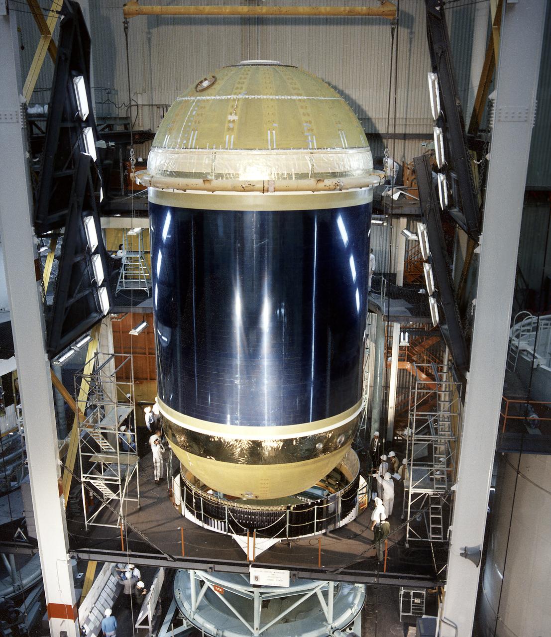
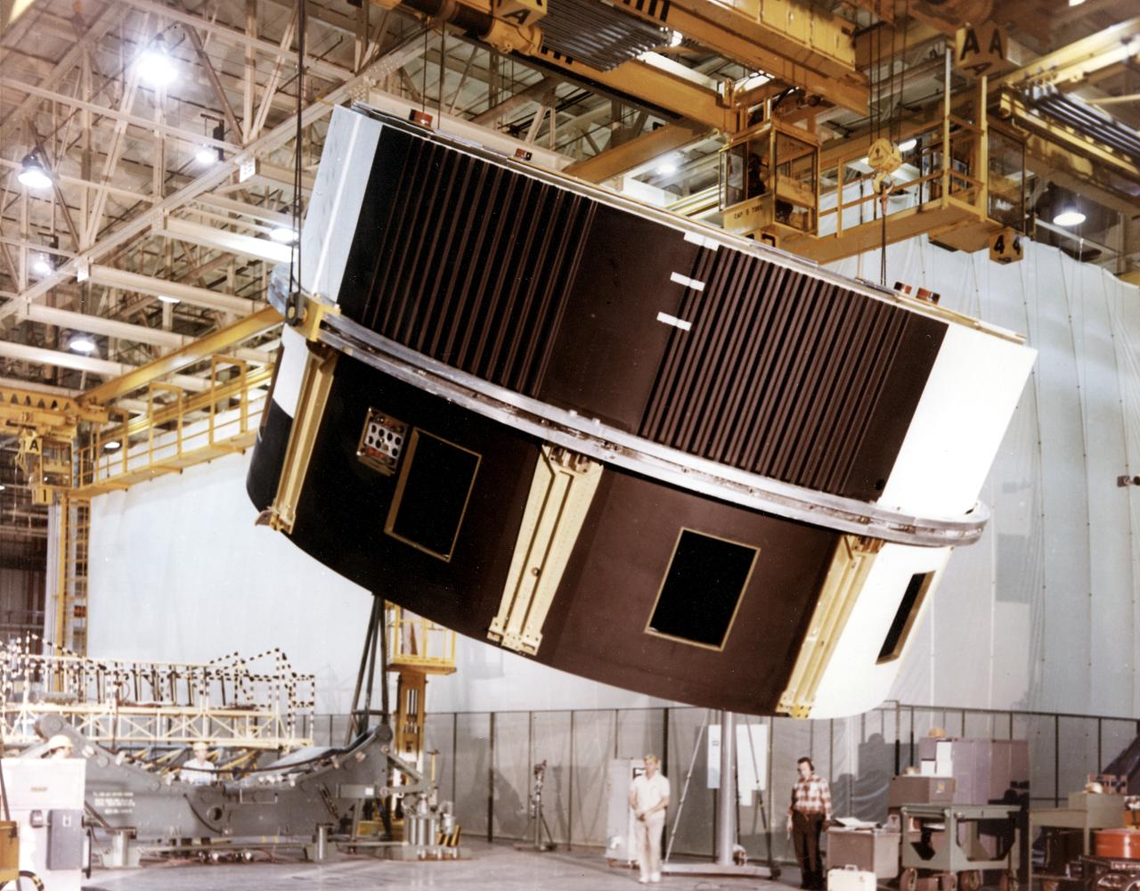
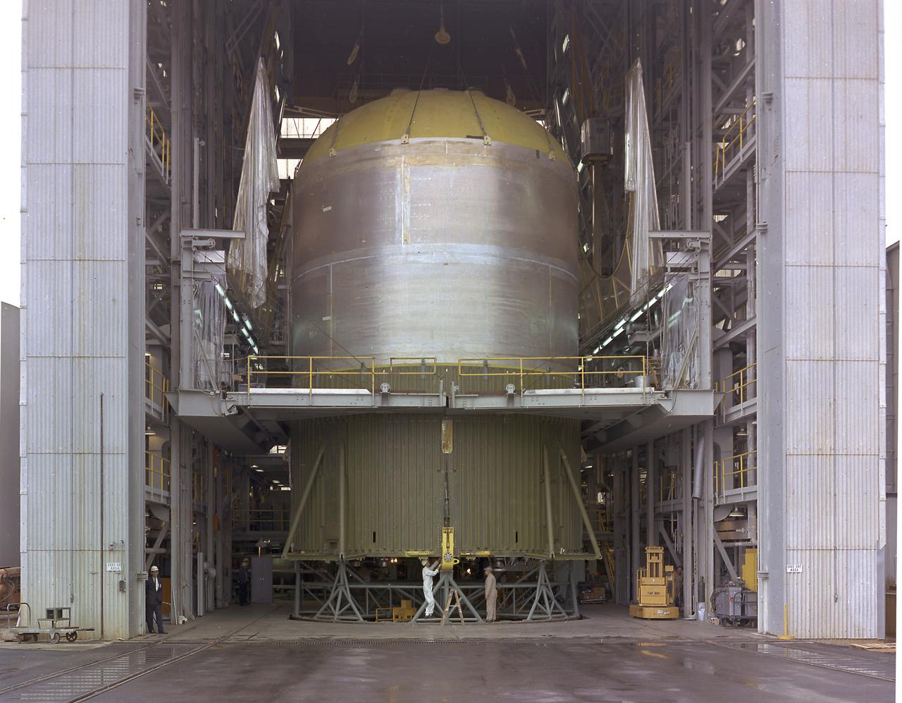
Assembling activities of the Skylab cluster are shown in this photograph. The Orbital Workshop (OWS) was lowered for joining to aft skirt and placed over the thrust structure inside the assembly tower. The OWS provided living and working quarters for the Skylab crew and the thruster provided short-term attitude control of the Skylab. The Marshall Space Flight Center had responsibilities for the design and development of the Skylab hardware, and management of experiments.
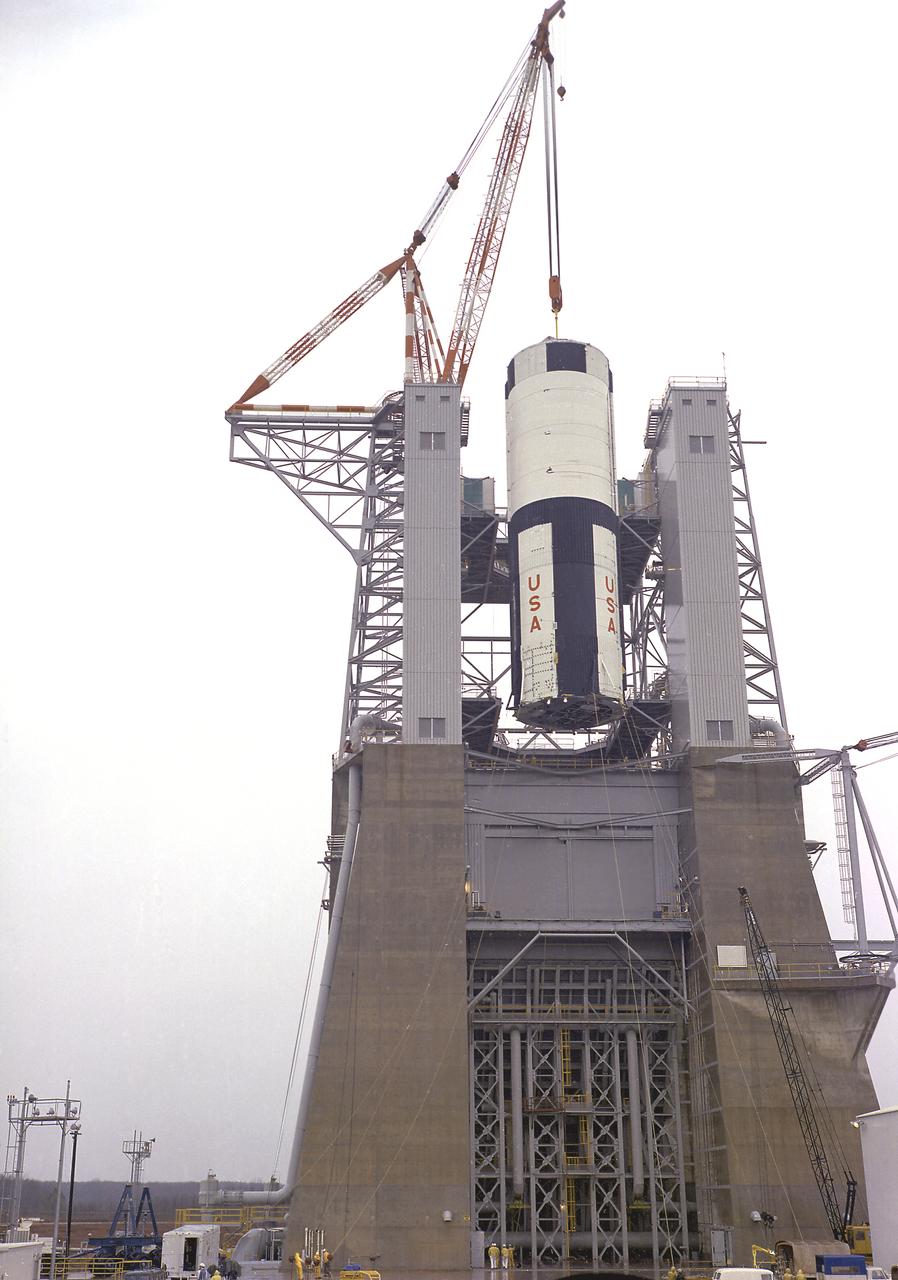
The S-IC-T stage was hoisted into the S-IC Static Test Stand at the Marshall Space Flight Center. The S-IC-T stage was a static test vehicle, not intended for flight. It was ground tested repeatedly over a period of many months to prove the vehicle's propulsion system. The 280,000-pound stage, 138 feet long and 33 feet in diameter, housed the fuel and liquid oxygen tanks that held a total of 4,400,000 pounds of liquid oxygen and kerosene. The two tanks were cornected by a 26-foot intertank section. Other parts of the booster included the forward skirt and the thrust structure, on which the engines were to be mounted. Five F-1 engines, each weighing 10 tons, gave the booster a total thrust of 7,500,000 pounds, roughly equivalent to 160 million horsepower.
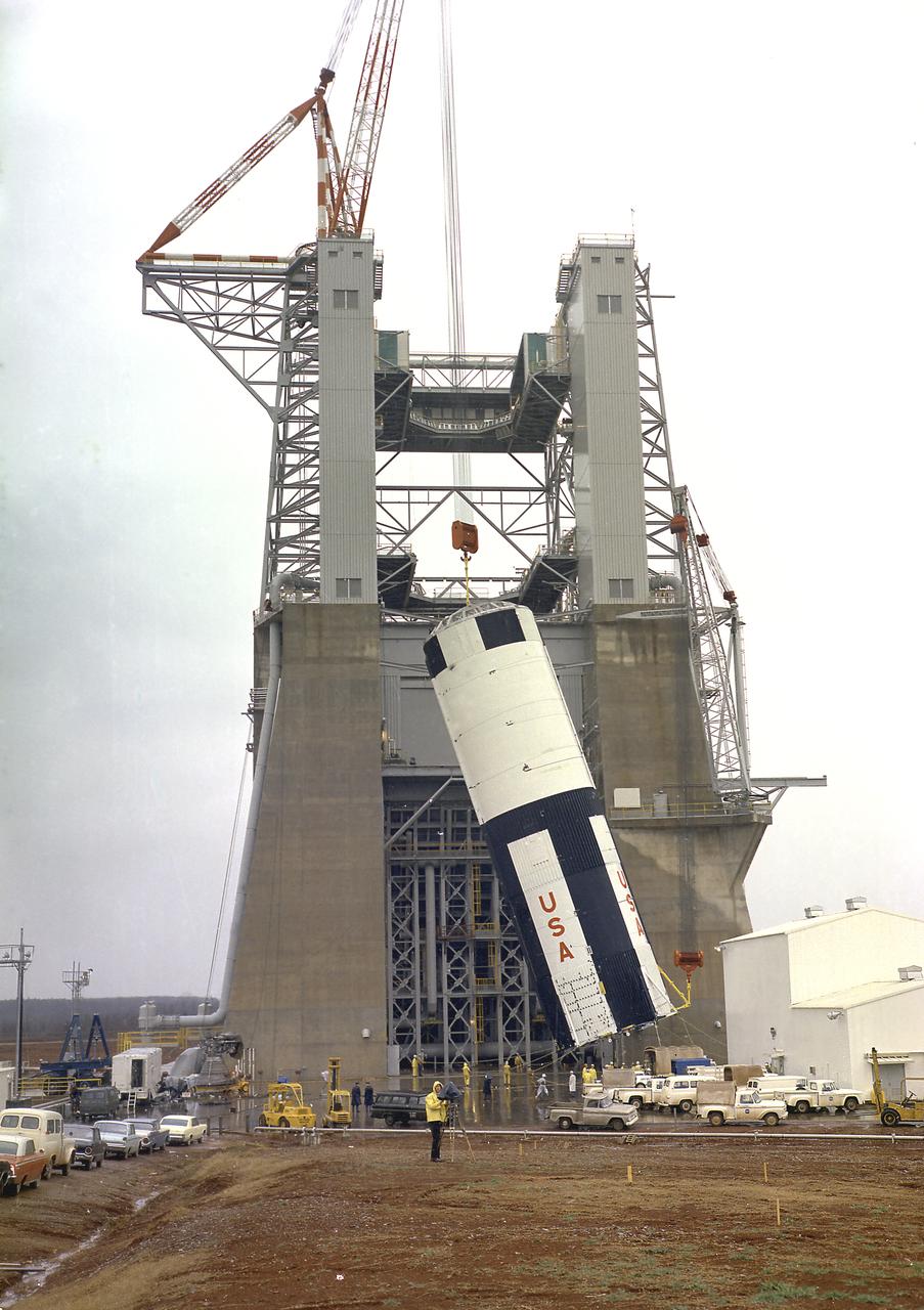
The S-IC-T stage was hoisted into the S-IC static test stand at the Marshall Space Flight Center. The S-IC-T stage was a static test vehicle not intended for flight. It was ground tested repeatedly over a period of many months to prove the vehicle's propulsion system. The 280,000-pound stage, 138 feet long and 33 feet in diameter, housed the fuel and liquid oxygen tanks that held a total of 4,400,000 pounds of liquid oxygen and kerosene. The two tanks are cornected by a 26-foot-long intertank section. Other parts of the booster included the forward skirt and the thrust structure, on which the engines were to be mounted. Five F-1 engines, each weighing 10 tons, gave the booster a total thrust of 7,500,000 pounds, roughly equivalent to 160 million horsepower.
This photograph depicts Marshall Space Flight Center employees, James Reagin, machinist (top); Floyd McGinnis, machinist; and Ernest Davis, experimental test mechanic (foreground), working on a mock up of the S-IC thrust structure. The S-IC stage is the first stage, or booster, of the 364-foot long Saturn V rocket that ultimately took astronauts to the Moon. The S-IC stage, burned over 15 tons of propellant per second during its 2.5 minutes of operation to take the vehicle to a height of about 36 miles and to a speed of about 6,000 miles per hour. The stage was 138 feet long and 33 feet in diameter. Operating at maximum power, all five of the engines produced 7,500,000 pounds of thrust.
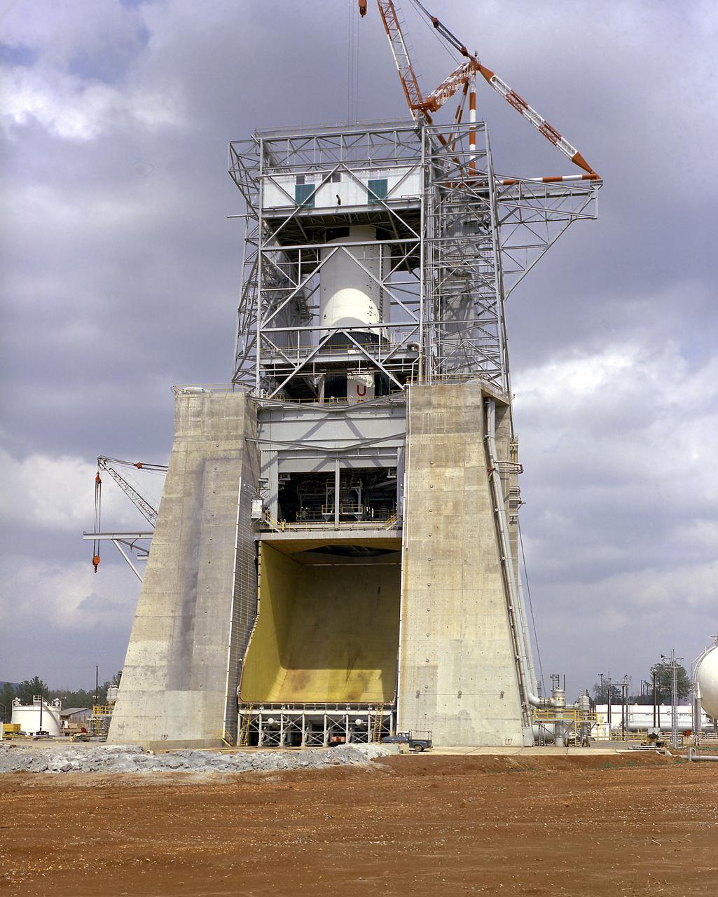
The S-IC-T stage (static firing stage) is installed and awaits the first static firing of all five F-1 engines at the Marshall Space Flight Center S-IC static test stand. Constructed in 1964, the S-IC static test stand was designed and constructed to develop and test the first stage of the Saturn V launch vehicle that used five F-1 engines. Each F-1 engine developed 1,500,000 pounds of thrust for a total liftoff thrust of 7,500,000 pounds. To handle this research and development effort, the stand contains 12,000,000 pounds of concrete on its base legs that are planted down to bedrock 40 feet below ground level. Of concrete and steel construction, the stand foundation walls are 4 feet thick, and topped by a crane with a 135-foot boom. With the boom in the up position, the stand is given an overall height of 405 feet, placing it among the highest structures in Alabama at the time.
The S-IC-T stage is hoisted into the S-IC static test stand at the Marshall Space Flight Center. The S-IC-T stage is a static test vehicle not intended for flight. It was ground tested repeatedly over a period of many months proving the vehicle's propulsion system. The 280,000-pound stage, 138 feet long and 33 feet in diameter, houses the fuel and liquid oxygen tanks that hold a total of 4,400,000 pounds of liquid oxygen and kerosene. The two tanks are cornected by a 26-foot-long intertank section. Other parts of the booster included the forward skirt and the thrust structure, on which the engines were to be mounted. Five F-1 engines, each weighing 10 tons, gave the booster a total thrust of 7,500,000 pounds, roughly equivalent to 160 million horsepower.

This photo shows the third of four RS-25 engines attached to the core stage for NASA’s Space Launch System rocket for the agency’s Artemis I mission to the Moon. NASA, Boeing and Aerojet Rocketdyne crews at NASA’s Michoud Assembly Facility in New Orleans attached the third RS-25 engine to the core stage for the SLS rocket on Nov. 5. The engine is one of four RS-25 engines that will provide more than 2 million pounds of thrust to send Artemis I, the first mission of SLS and NASA’s Orion spacecraft, to the Moon. The first two RS-25 engines were structurally mated to the stage in October. Following the mate, engineers and technicians will integrate the propulsion and electrical systems within the structures to complete the installation. Integration of the RS-25 engines to the recently completed core stage structure is a collaborative, multistep process for NASA and its partners Boeing, the core stage lead contractor, and Aerojet Rocketdyne, the RS-25 engines lead contractor. Offering more payload mass, volume capability and energy to speed missions through space, the SLS rocket, along with NASA’s Gateway in lunar orbit and Orion, is part of NASA’s backbone for deep space exploration and the Artemis lunar program. No other rocket is capable of carrying astronauts in Orion around the Moon in a single mission.
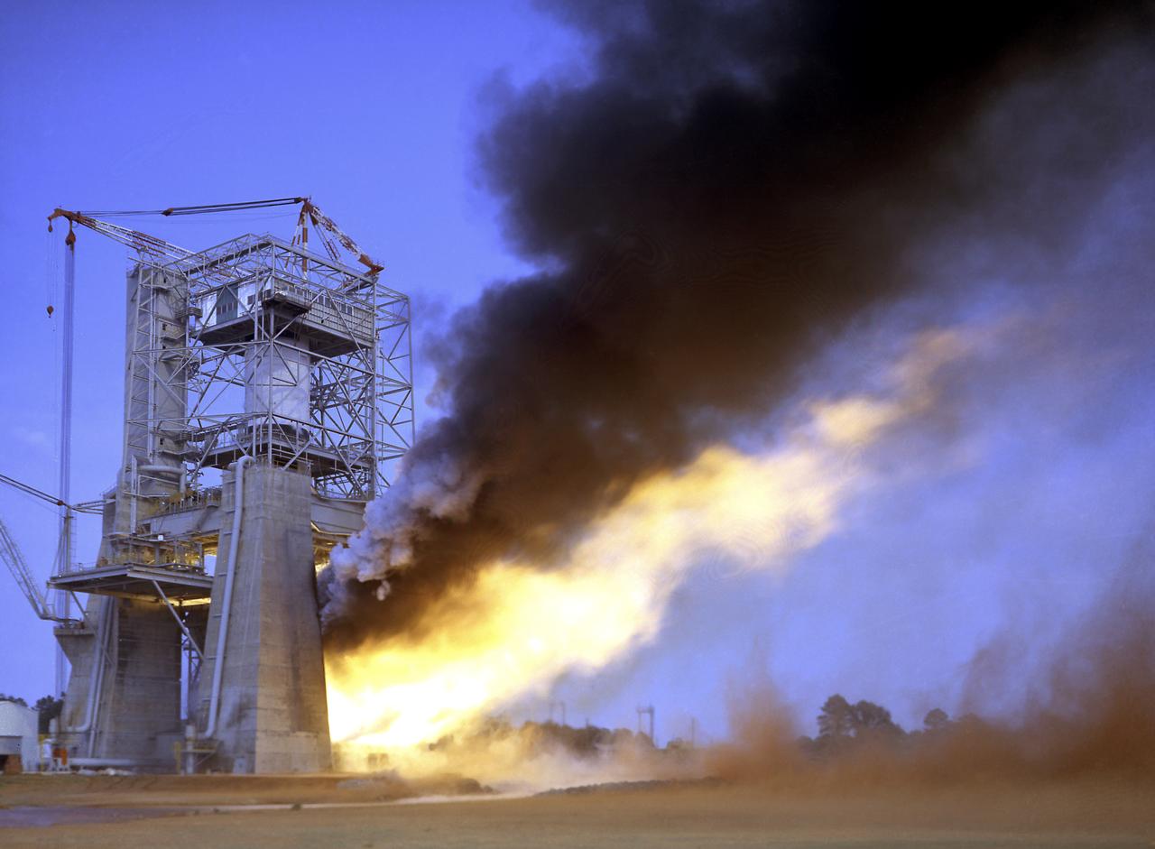
This photograph depicts a view of the test firing of all five F-1 engines for the Saturn V S-IC test stage at the Marshall Space Flight Center. The S-IC stage is the first stage, or booster, of a 364-foot long rocket that ultimately took astronauts to the Moon. Operating at maximum power, all five of the engines produced 7,500,000 pounds of thrust. The S-IC Static Test Stand was designed and constructed with the strength of hundreds of tons of steel and cement, planted down to bedrock 40 feet below ground level, and was required to hold down the brute force of the 7,500,000-pound thrust. The structure was topped by a crane with a 135-foot boom. With the boom in the up position, the stand was given an overall height of 405 feet, placing it among the highest structures in Alabama at the time. When the Saturn V S-IC first stage was placed upright in the stand , the five F-1 engine nozzles pointed downward on a 1,900-ton, water-cooled deflector. To prevent melting damage, water was sprayed through small holes in the deflector at the rate 320,000 gallons per minutes.
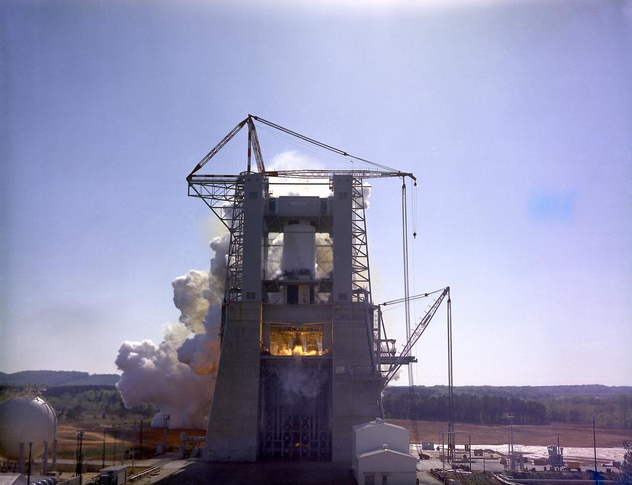
This photograph depicts a dramatic view of the first test firing of all five F-1 engines for the Saturn V S-IC stage at the Marshall Space Flight Center. The testing lasted a full duration of 6.5 seconds. It also marked the first test performed in the new S-IC static test stand and the first test using the new control blockhouse. The S-IC stage is the first stage, or booster, of a 364-foot long rocket that ultimately took astronauts to the Moon. Operating at maximum power, all five of the engines produced 7,500,000 pounds of thrust. Required to hold down the brute force of a 7,500,000-pound thrust, the S-IC static test stand was designed and constructed with the strength of hundreds of tons of steel and cement, planted down to bedrock 40 feet below ground level. The structure was topped by a crane with a 135-foot boom. With the boom in the up position, the stand was given an overall height of 405 feet, placing it among the highest structures in Alabama at the time. When the Saturn V S-IC first stage was placed upright in the stand , the five F-1 engine nozzles pointed downward on a 1,900 ton, water-cooled deflector. To prevent melting damage, water was sprayed through small holes in the deflector at the rate 320,000 gallons per minute.
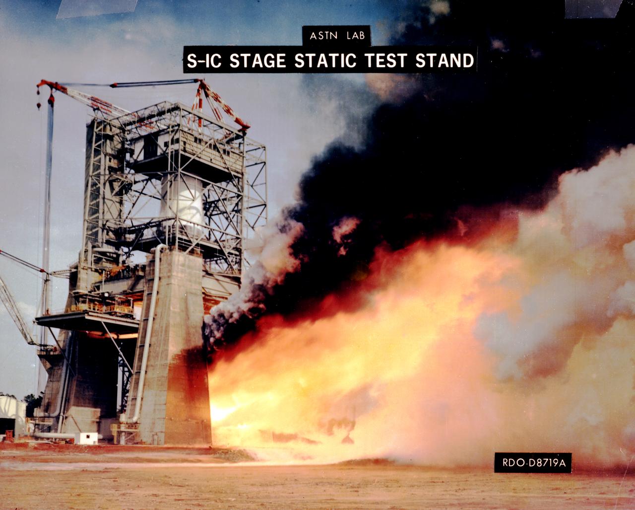
This photograph depicts a view of the test firing of all five F-1 engines for the Saturn V S-IC test stage at the Marshall Space Flight Center. The S-IC stage is the first stage, or booster, of a 364-foot long rocket that ultimately took astronauts to the Moon. Operating at maximum power, all five of the engines produced 7,500,000 pounds of thrust. The S-IC Static Test Stand was designed and constructed with the strength of hundreds of tons of steel and cement, planted down to bedrock 40 feet below ground level, and was required to hold down the brute force of the 7,500,000-pound thrust. The structure was topped by a crane with a 135-foot boom. With the boom in the up position, the stand was given an overall height of 405 feet, placing it among the highest structures in Alabama at the time. When the Saturn V S-IC first stage was placed upright in the stand , the five F-1 engine nozzles pointed downward on a 1,900-ton, water-cooled deflector. To prevent melting damage, water was sprayed through small holes in the deflector at the rate 320,000 gallons per minutes
NASA finished assembling and joining the main structural components for the largest rocket stage the agency has built since the Saturn V that sent Apollo astronauts to the Moon. Engineers at the agency’s Michoud Assembly Facility in New Orleans connected the last of the five sections of the Space Launch System (SLS) rocket core stage Sept. 19. The stage will produce 2 million pounds of thrust to send Artemis I, the first flight SLS and NASA’s Orion spacecraft to the Moon. The engine section is located at the bottom of the 212-foot-tall stage and houses the four RS-25 engines. The core stage’s two liquid propellant tanks and four RS-25 engines will produce more than 2 million pounds of thrust to send the SLS rocket and Orion on the Artemis lunar missions. The engine section houses the four RS-25 engines and includes vital systems for mounting, controlling and delivering fuel form the propellant tanks to the rocket’s engines. Offering more payload mass, volume capability and energy to speed missions through space, the SLS rocket, along with NASA’s Gateway in lunar orbit and Orion, is part of NASA’s backbone for deep space exploration and the Artemis lunar program. No other rocket is capable of carrying astronauts in Orion around the Moon in a single mission.
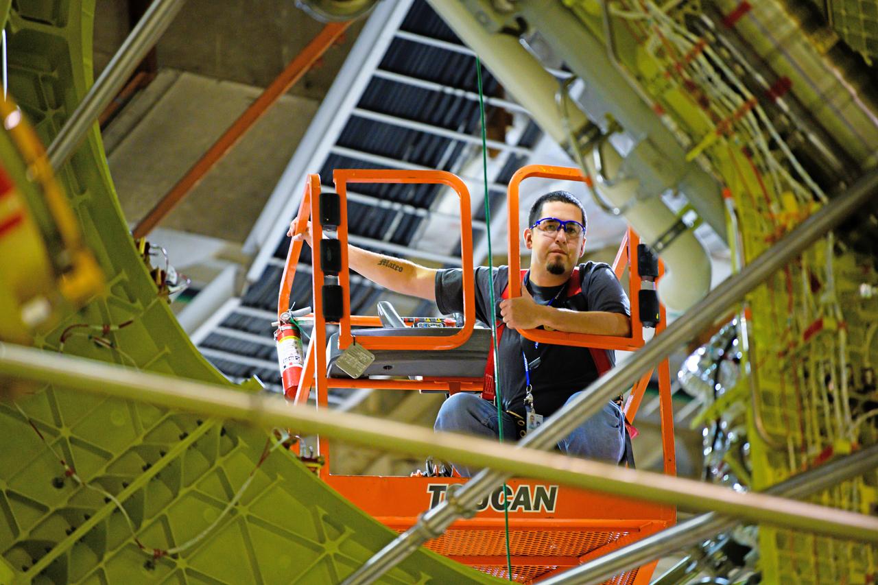
NASA finished assembling and joining the main structural components for the largest rocket stage the agency has built since the Saturn V that sent Apollo astronauts to the Moon. Engineers at the agency’s Michoud Assembly Facility in New Orleans connected the last of the five sections of the Space Launch System (SLS) rocket core stage Sept. 19. The stage will produce 2 million pounds of thrust to send Artemis I, the first flight SLS and NASA’s Orion spacecraft to the Moon. The engine section is located at the bottom of the 212-foot-tall stage and houses the four RS-25 engines. The core stage’s two liquid propellant tanks and four RS-25 engines will produce more than 2 million pounds of thrust to send the SLS rocket and Orion on the Artemis lunar missions. The engine section houses the four RS-25 engines and includes vital systems for mounting, controlling and delivering fuel form the propellant tanks to the rocket’s engines. Offering more payload mass, volume capability and energy to speed missions through space, the SLS rocket, along with NASA’s Gateway in lunar orbit and Orion, is part of NASA’s backbone for deep space exploration and the Artemis lunar program. No other rocket is capable of carrying astronauts in Orion around the Moon in a single mission.
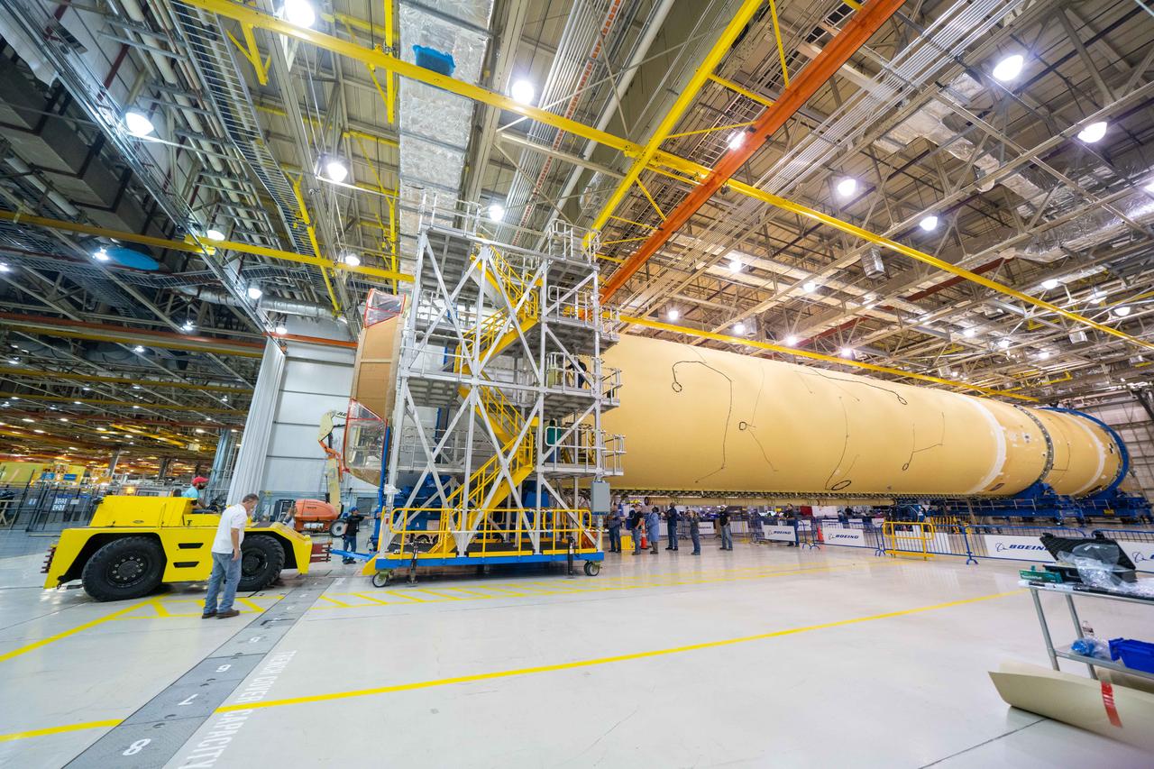
NASA finished assembling and joining the main structural components for the largest rocket stage the agency has built since the Saturn V that sent Apollo astronauts to the Moon. Engineers at the agency’s Michoud Assembly Facility in New Orleans connected the last of the five sections of the Space Launch System (SLS) rocket core stage Sept. 19. The stage will produce 2 million pounds of thrust to send Artemis I, the first flight SLS and NASA’s Orion spacecraft to the Moon. The engine section is located at the bottom of the 212-foot-tall stage and houses the four RS-25 engines. The core stage’s two liquid propellant tanks and four RS-25 engines will produce more than 2 million pounds of thrust to send the SLS rocket and Orion on the Artemis lunar missions. The engine section houses the four RS-25 engines and includes vital systems for mounting, controlling and delivering fuel form the propellant tanks to the rocket’s engines. Offering more payload mass, volume capability and energy to speed missions through space, the SLS rocket, along with NASA’s Gateway in lunar orbit and Orion, is part of NASA’s backbone for deep space exploration and the Artemis lunar program. No other rocket is capable of carrying astronauts in Orion around the Moon in a single mission.
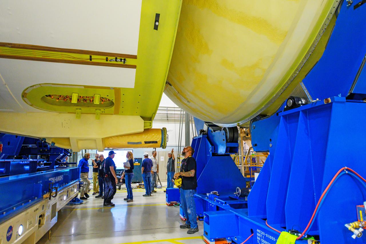
NASA finished assembling and joining the main structural components for the largest rocket stage the agency has built since the Saturn V that sent Apollo astronauts to the Moon. Engineers at the agency’s Michoud Assembly Facility in New Orleans connected the last of the five sections of the Space Launch System (SLS) rocket core stage Sept. 19. The stage will produce 2 million pounds of thrust to send Artemis I, the first flight SLS and NASA’s Orion spacecraft to the Moon. The engine section is located at the bottom of the 212-foot-tall stage and houses the four RS-25 engines. The core stage’s two liquid propellant tanks and four RS-25 engines will produce more than 2 million pounds of thrust to send the SLS rocket and Orion on the Artemis lunar missions. The engine section houses the four RS-25 engines and includes vital systems for mounting, controlling and delivering fuel form the propellant tanks to the rocket’s engines. Offering more payload mass, volume capability and energy to speed missions through space, the SLS rocket, along with NASA’s Gateway in lunar orbit and Orion, is part of NASA’s backbone for deep space exploration and the Artemis lunar program. No other rocket is capable of carrying astronauts in Orion around the Moon in a single mission.
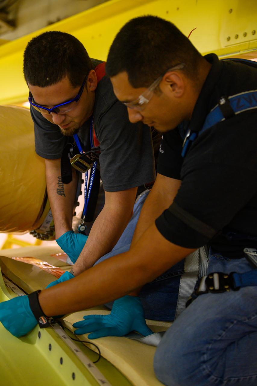
NASA finished assembling and joining the main structural components for the largest rocket stage the agency has built since the Saturn V that sent Apollo astronauts to the Moon. Engineers at the agency’s Michoud Assembly Facility in New Orleans connected the last of the five sections of the Space Launch System (SLS) rocket core stage Sept. 19. The stage will produce 2 million pounds of thrust to send Artemis I, the first flight SLS and NASA’s Orion spacecraft to the Moon. The engine section is located at the bottom of the 212-foot-tall stage and houses the four RS-25 engines. The core stage’s two liquid propellant tanks and four RS-25 engines will produce more than 2 million pounds of thrust to send the SLS rocket and Orion on the Artemis lunar missions. The engine section houses the four RS-25 engines and includes vital systems for mounting, controlling and delivering fuel form the propellant tanks to the rocket’s engines. Offering more payload mass, volume capability and energy to speed missions through space, the SLS rocket, along with NASA’s Gateway in lunar orbit and Orion, is part of NASA’s backbone for deep space exploration and the Artemis lunar program. No other rocket is capable of carrying astronauts in Orion around the Moon in a single mission.
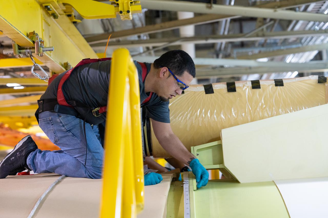
NASA finished assembling and joining the main structural components for the largest rocket stage the agency has built since the Saturn V that sent Apollo astronauts to the Moon. Engineers at the agency’s Michoud Assembly Facility in New Orleans connected the last of the five sections of the Space Launch System (SLS) rocket core stage Sept. 19. The stage will produce 2 million pounds of thrust to send Artemis I, the first flight SLS and NASA’s Orion spacecraft to the Moon. The engine section is located at the bottom of the 212-foot-tall stage and houses the four RS-25 engines. The core stage’s two liquid propellant tanks and four RS-25 engines will produce more than 2 million pounds of thrust to send the SLS rocket and Orion on the Artemis lunar missions. The engine section houses the four RS-25 engines and includes vital systems for mounting, controlling and delivering fuel form the propellant tanks to the rocket’s engines. Offering more payload mass, volume capability and energy to speed missions through space, the SLS rocket, along with NASA’s Gateway in lunar orbit and Orion, is part of NASA’s backbone for deep space exploration and the Artemis lunar program. No other rocket is capable of carrying astronauts in Orion around the Moon in a single mission.
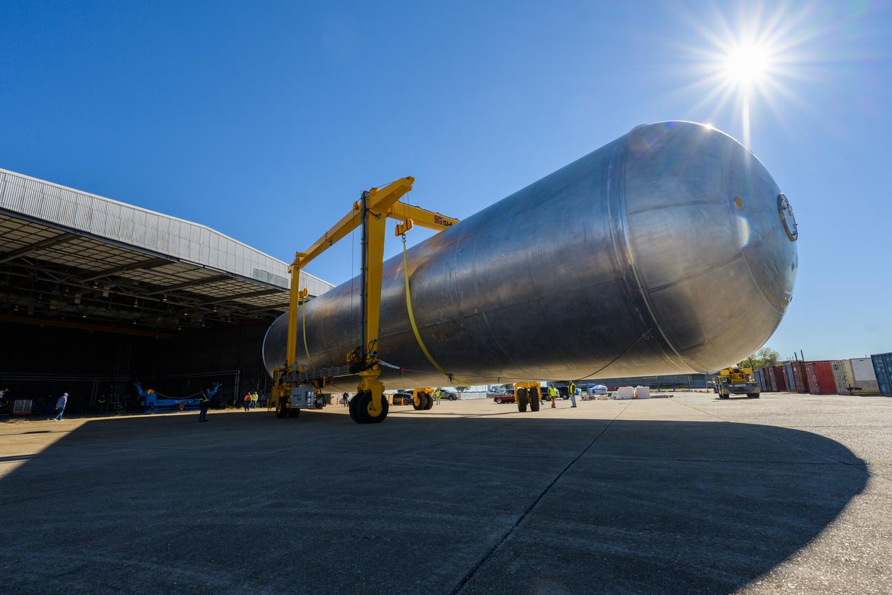
The liquid hydrogen tank that will be part of the Space Launch System rocket’s core stage is being prepared for the Artemis III mission at NASA’s Michoud Assembly Facility in New Orleans. Eventually, the tank will be connected to the engine section that will house the four RS-25 engines. Once the aft simulator is attached, the LH2 tank undergoes non-destructive evaluation, which will test weld strength and ensure the tank is structurally sound. The SLS core stage is made up of five unique elements: the forward skirt, liquid oxygen tank, intertank, liquid hydrogen tank, and the engine section. The tank holds 537,000 gallons of liquid hydrogen cooled to minus 432 degrees Fahrenheit and sits between the core stage’s intertank and engine section. The liquid hydrogen hardware, along with the liquid oxygen tank, will provide propellant to the four RS-25 engines at the bottom of the core stage to produce more than two million pounds of thrust to help launch the Artemis III mission to the Moon. Together with its four RS-25 engines, the rocket’s massive 212-foot-tall core stage — the largest stage NASA has ever built — and its twin solid rocket boosters will produce 8.8 million pounds of thrust to send NASA’s Orion spacecraft, astronauts and supplies beyond Earth’s orbit to the Moon.
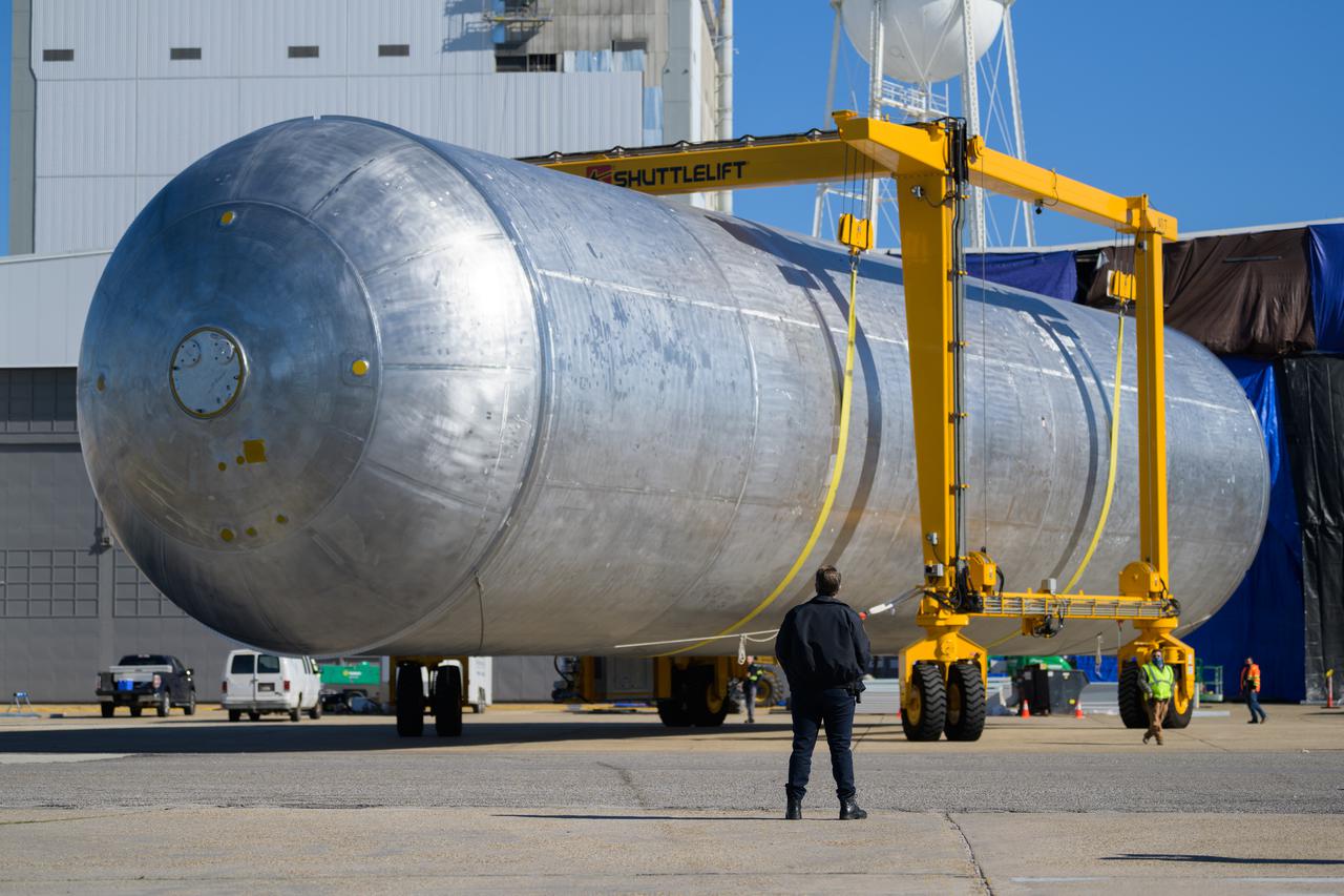
The liquid hydrogen tank that will be part of the Space Launch System rocket’s core stage is being prepared for the Artemis III mission at NASA’s Michoud Assembly Facility in New Orleans. Eventually, the tank will be connected to the engine section that will house the four RS-25 engines. Once the aft simulator is attached, the LH2 tank undergoes non-destructive evaluation, which will test weld strength and ensure the tank is structurally sound. The SLS core stage is made up of five unique elements: the forward skirt, liquid oxygen tank, intertank, liquid hydrogen tank, and the engine section. The tank holds 537,000 gallons of liquid hydrogen cooled to minus 432 degrees Fahrenheit and sits between the core stage’s intertank and engine section. The liquid hydrogen hardware, along with the liquid oxygen tank, will provide propellant to the four RS-25 engines at the bottom of the core stage to produce more than two million pounds of thrust to help launch the Artemis III mission to the Moon. Together with its four RS-25 engines, the rocket’s massive 212-foot-tall core stage — the largest stage NASA has ever built — and its twin solid rocket boosters will produce 8.8 million pounds of thrust to send NASA’s Orion spacecraft, astronauts and supplies beyond Earth’s orbit to the Moon.
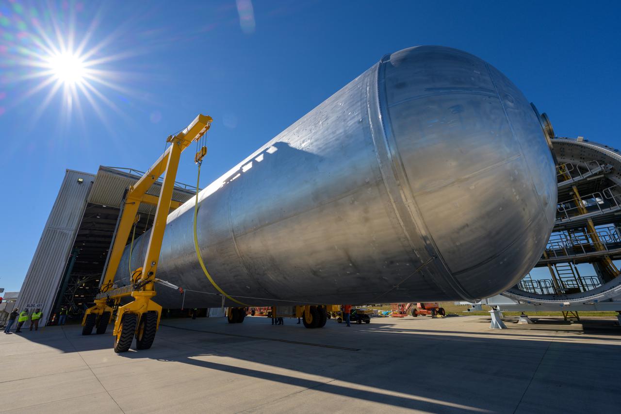
The liquid hydrogen tank that will be part of the Space Launch System rocket’s core stage is being prepared for the Artemis III mission at NASA’s Michoud Assembly Facility in New Orleans. Eventually, the tank will be connected to the engine section that will house the four RS-25 engines. Once the aft simulator is attached, the LH2 tank undergoes non-destructive evaluation, which will test weld strength and ensure the tank is structurally sound. The SLS core stage is made up of five unique elements: the forward skirt, liquid oxygen tank, intertank, liquid hydrogen tank, and the engine section. The tank holds 537,000 gallons of liquid hydrogen cooled to minus 432 degrees Fahrenheit and sits between the core stage’s intertank and engine section. The liquid hydrogen hardware, along with the liquid oxygen tank, will provide propellant to the four RS-25 engines at the bottom of the core stage to produce more than two million pounds of thrust to help launch the Artemis III mission to the Moon. Together with its four RS-25 engines, the rocket’s massive 212-foot-tall core stage — the largest stage NASA has ever built — and its twin solid rocket boosters will produce 8.8 million pounds of thrust to send NASA’s Orion spacecraft, astronauts and supplies beyond Earth’s orbit to the Moon.
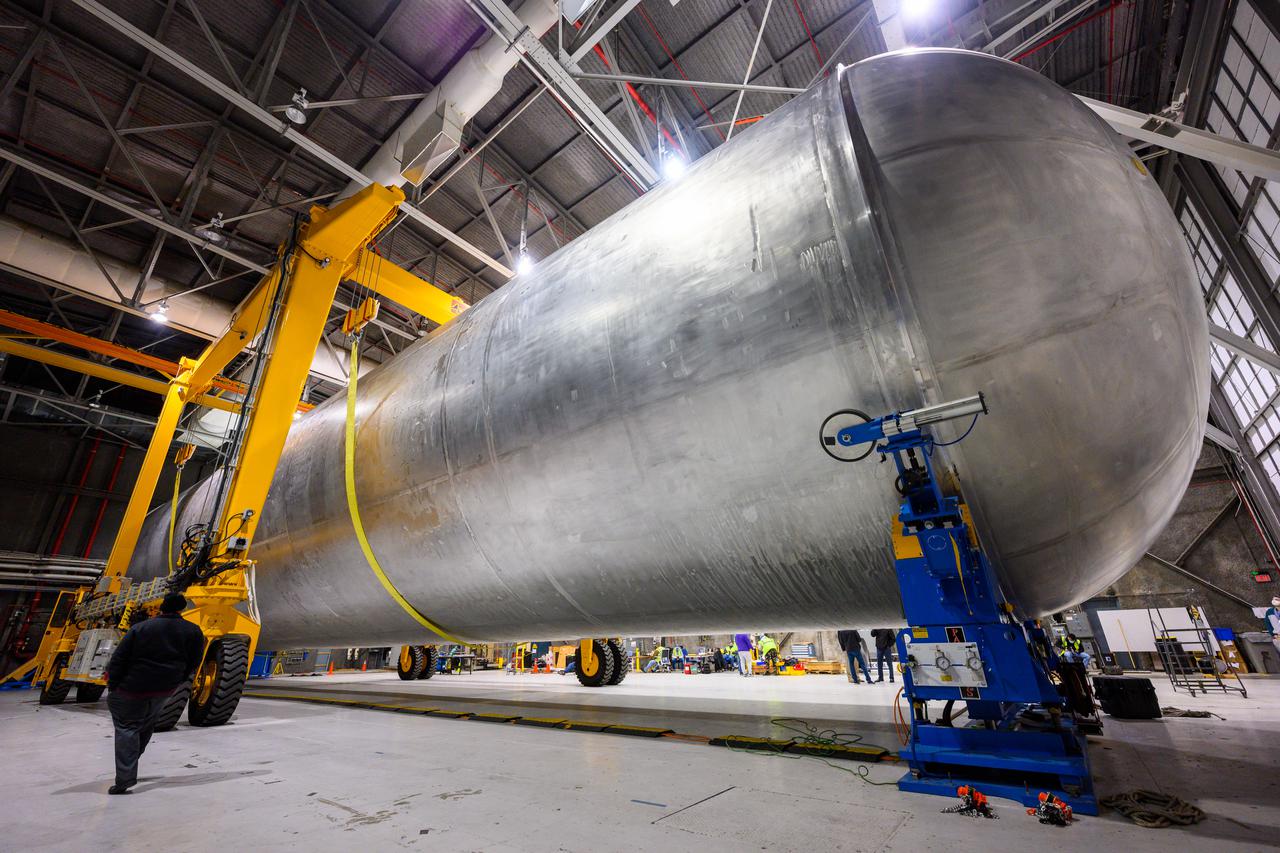
The liquid hydrogen tank that will be part of the Space Launch System rocket’s core stage is being prepared for the Artemis III mission at NASA’s Michoud Assembly Facility in New Orleans. Eventually, the tank will be connected to the engine section that will house the four RS-25 engines. Once the aft simulator is attached, the LH2 tank undergoes non-destructive evaluation, which will test weld strength and ensure the tank is structurally sound. The SLS core stage is made up of five unique elements: the forward skirt, liquid oxygen tank, intertank, liquid hydrogen tank, and the engine section. The tank holds 537,000 gallons of liquid hydrogen cooled to minus 432 degrees Fahrenheit and sits between the core stage’s intertank and engine section. The liquid hydrogen hardware, along with the liquid oxygen tank, will provide propellant to the four RS-25 engines at the bottom of the core stage to produce more than two million pounds of thrust to help launch the Artemis III mission to the Moon. Together with its four RS-25 engines, the rocket’s massive 212-foot-tall core stage — the largest stage NASA has ever built — and its twin solid rocket boosters will produce 8.8 million pounds of thrust to send NASA’s Orion spacecraft, astronauts and supplies beyond Earth’s orbit to the Moon.
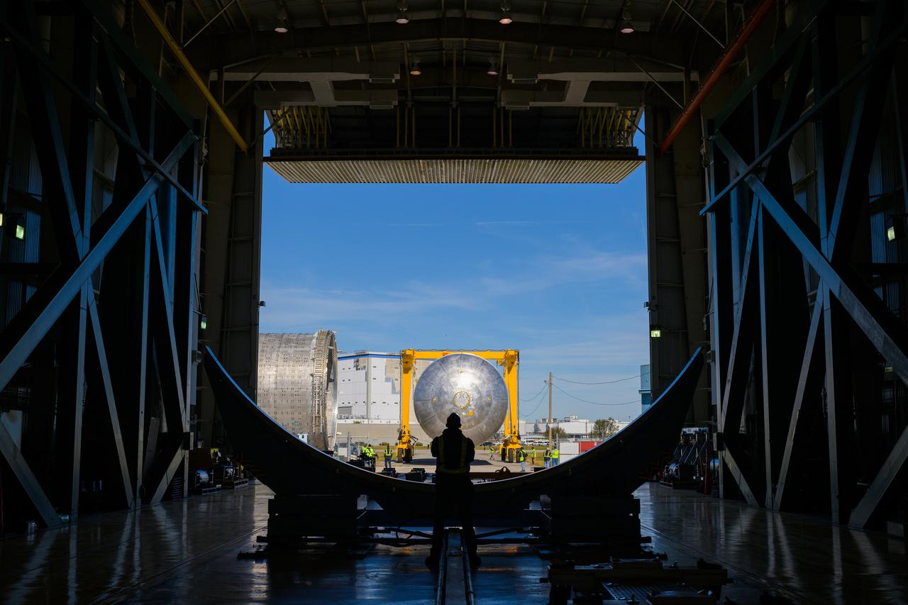
The liquid hydrogen tank that will be part of the Space Launch System rocket’s core stage is being prepared for the Artemis III mission at NASA’s Michoud Assembly Facility in New Orleans. Eventually, the tank will be connected to the engine section that will house the four RS-25 engines. Once the aft simulator is attached, the LH2 tank undergoes non-destructive evaluation, which will test weld strength and ensure the tank is structurally sound. The SLS core stage is made up of five unique elements: the forward skirt, liquid oxygen tank, intertank, liquid hydrogen tank, and the engine section. The tank holds 537,000 gallons of liquid hydrogen cooled to minus 432 degrees Fahrenheit and sits between the core stage’s intertank and engine section. The liquid hydrogen hardware, along with the liquid oxygen tank, will provide propellant to the four RS-25 engines at the bottom of the core stage to produce more than two million pounds of thrust to help launch the Artemis III mission to the Moon. Together with its four RS-25 engines, the rocket’s massive 212-foot-tall core stage — the largest stage NASA has ever built — and its twin solid rocket boosters will produce 8.8 million pounds of thrust to send NASA’s Orion spacecraft, astronauts and supplies beyond Earth’s orbit to the Moon.
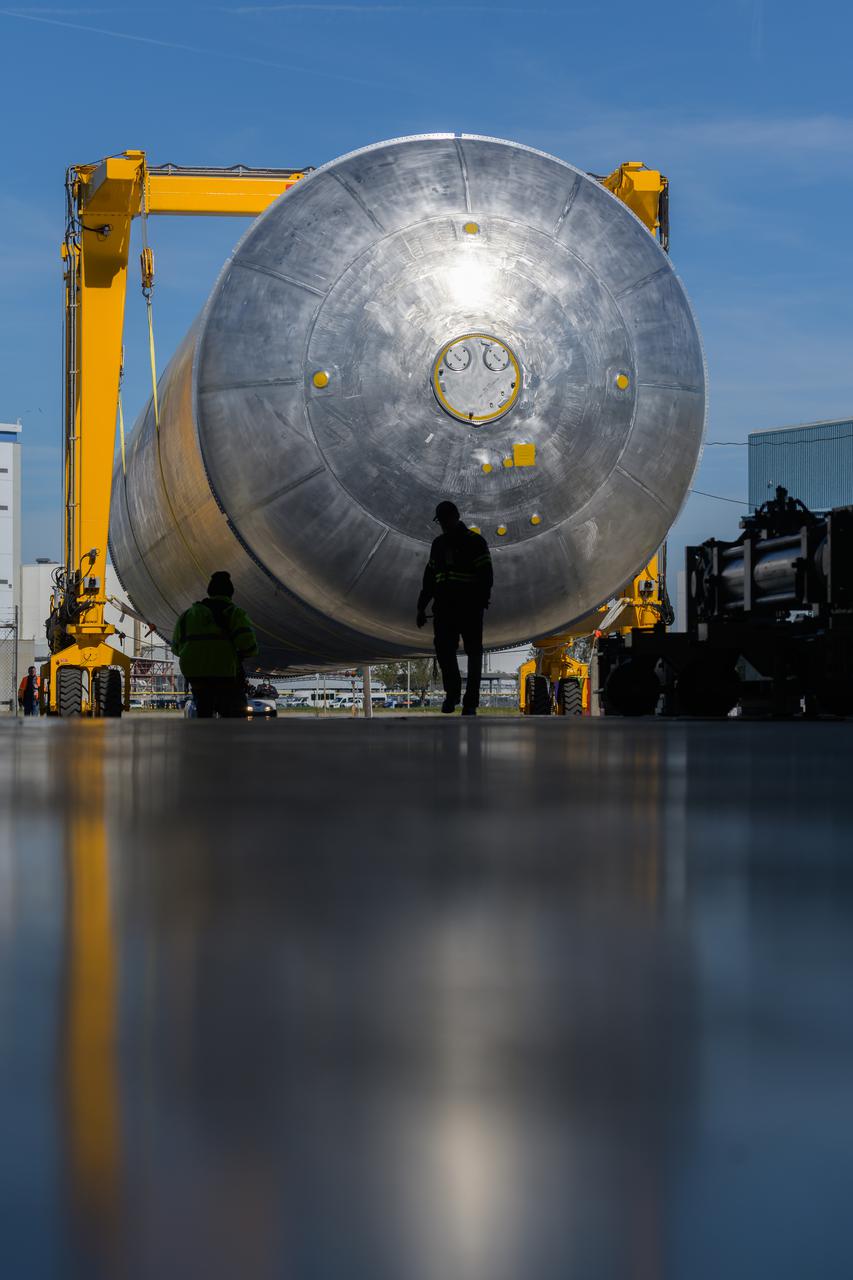
The liquid hydrogen tank that will be part of the Space Launch System rocket’s core stage is being prepared for the Artemis III mission at NASA’s Michoud Assembly Facility in New Orleans. Eventually, the tank will be connected to the engine section that will house the four RS-25 engines. Once the aft simulator is attached, the LH2 tank undergoes non-destructive evaluation, which will test weld strength and ensure the tank is structurally sound. The SLS core stage is made up of five unique elements: the forward skirt, liquid oxygen tank, intertank, liquid hydrogen tank, and the engine section. The tank holds 537,000 gallons of liquid hydrogen cooled to minus 432 degrees Fahrenheit and sits between the core stage’s intertank and engine section. The liquid hydrogen hardware, along with the liquid oxygen tank, will provide propellant to the four RS-25 engines at the bottom of the core stage to produce more than two million pounds of thrust to help launch the Artemis III mission to the Moon. Together with its four RS-25 engines, the rocket’s massive 212-foot-tall core stage — the largest stage NASA has ever built — and its twin solid rocket boosters will produce 8.8 million pounds of thrust to send NASA’s Orion spacecraft, astronauts and supplies beyond Earth’s orbit to the Moon.
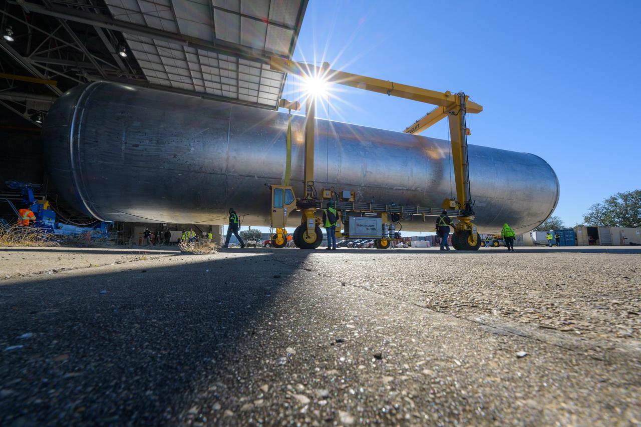
The liquid hydrogen tank that will be part of the Space Launch System rocket’s core stage is being prepared for the Artemis III mission at NASA’s Michoud Assembly Facility in New Orleans. Eventually, the tank will be connected to the engine section that will house the four RS-25 engines. Once the aft simulator is attached, the LH2 tank undergoes non-destructive evaluation, which will test weld strength and ensure the tank is structurally sound. The SLS core stage is made up of five unique elements: the forward skirt, liquid oxygen tank, intertank, liquid hydrogen tank, and the engine section. The tank holds 537,000 gallons of liquid hydrogen cooled to minus 432 degrees Fahrenheit and sits between the core stage’s intertank and engine section. The liquid hydrogen hardware, along with the liquid oxygen tank, will provide propellant to the four RS-25 engines at the bottom of the core stage to produce more than two million pounds of thrust to help launch the Artemis III mission to the Moon. Together with its four RS-25 engines, the rocket’s massive 212-foot-tall core stage — the largest stage NASA has ever built — and its twin solid rocket boosters will produce 8.8 million pounds of thrust to send NASA’s Orion spacecraft, astronauts and supplies beyond Earth’s orbit to the Moon.
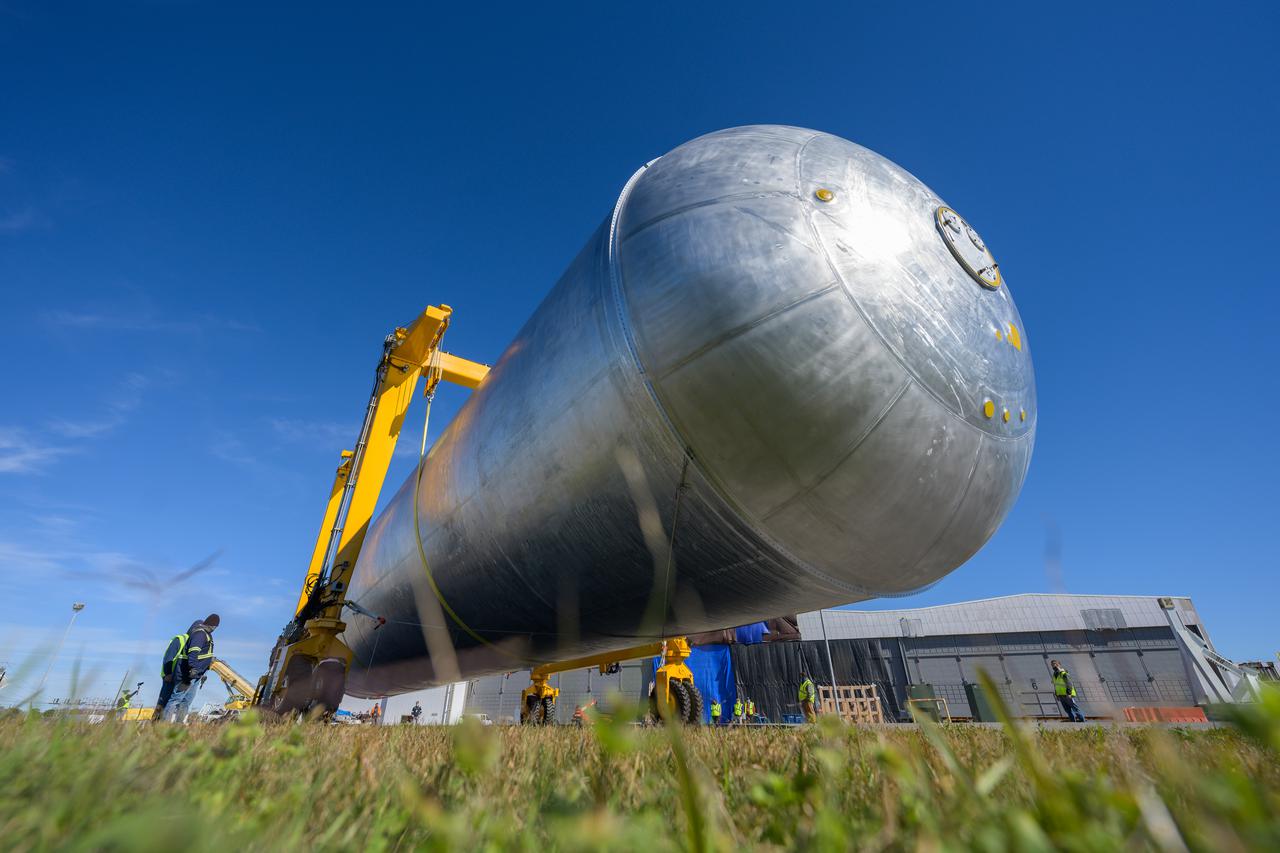
The liquid hydrogen tank that will be part of the Space Launch System rocket’s core stage is being prepared for the Artemis III mission at NASA’s Michoud Assembly Facility in New Orleans. Eventually, the tank will be connected to the engine section that will house the four RS-25 engines. Once the aft simulator is attached, the LH2 tank undergoes non-destructive evaluation, which will test weld strength and ensure the tank is structurally sound. The SLS core stage is made up of five unique elements: the forward skirt, liquid oxygen tank, intertank, liquid hydrogen tank, and the engine section. The tank holds 537,000 gallons of liquid hydrogen cooled to minus 432 degrees Fahrenheit and sits between the core stage’s intertank and engine section. The liquid hydrogen hardware, along with the liquid oxygen tank, will provide propellant to the four RS-25 engines at the bottom of the core stage to produce more than two million pounds of thrust to help launch the Artemis III mission to the Moon. Together with its four RS-25 engines, the rocket’s massive 212-foot-tall core stage — the largest stage NASA has ever built — and its twin solid rocket boosters will produce 8.8 million pounds of thrust to send NASA’s Orion spacecraft, astronauts and supplies beyond Earth’s orbit to the Moon.