Leonardo Barreda inspects SLS Core Stage Thruster Vector Control Hardware.
Leonardo Barreda inspects SLS Core Stage Thruster Vector Control
Advanced Electric Propulsion System, AEPS, Engineering Test Unit 2, ETU-2, Thruster Hardware
Advanced Electric Propulsion System, AEPS, Engineering Test U...
Advanced Electric Propulsion System, AEPS, Engineering Test Unit 2, ETU-2, Thruster Hardware
Advanced Electric Propulsion System, AEPS, Engineering Test Unit
Advanced Electric Propulsion System, AEPS, Engineering Test Unit 2, ETU-2, Thruster Hardware
Advanced Electric Propulsion System, AEPS, Engineering Test U...
Advanced Electric Propulsion System, AEPS, Engineering Test Unit 2, ETU-2, Thruster Hardware
Advanced Electric Propulsion System, AEPS, Engineering Test U...
Advanced Electric Propulsion System, AEPS, Engineering Test Unit 2, ETU-2, Thruster Hardware
Advanced Electric Propulsion System, AEPS, Engineering Test U...
Advanced Electric Propulsion System, AEPS, Engineering Test Unit 2, ETU-2, Thruster Hardware
Advanced Electric Propulsion System, AEPS, Engineering Test U...
Advanced Electric Propulsion System, AEPS, Engineering Test Unit 2, ETU-2, Thruster Hardware
Advanced Electric Propulsion System, AEPS, Engineering Test U...
Advanced Electric Propulsion System, AEPS, Engineering Test Unit 2, ETU-2, Thruster Hardware
Advanced Electric Propulsion System, AEPS, Engineering Test U...
Advanced Electric Propulsion System, AEPS, Engineering Test Unit 2, ETU-2, Thruster Hardware
Advanced Electric Propulsion System, AEPS, Engineering Test U...
Advanced Electric Propulsion System, AEPS, Engineering Test Unit 2, ETU-2, Thruster Hardware
Advanced Electric Propulsion System, AEPS, Engineering Test U...
Advanced Electric Propulsion System, AEPS, Engineering Test Unit 2, ETU-2, Thruster Hardware
Advanced Electric Propulsion System, AEPS, Engineering Test U...
Advanced Electric Propulsion System, AEPS, Engineering Test Unit 2, ETU-2, Thruster Hardware
Advanced Electric Propulsion System, AEPS, Engineering Test U...
Advanced Electric Propulsion System, AEPS, Engineering Test Unit 2, ETU-2, Thruster Hardware
Advanced Electric Propulsion System, AEPS, Engineering Test U...
T160E HULL THRUSTER FLIGHT HARDWARE
GRC-1999-C-02550
T160E HULL THRUSTER FLIGHT HARDWARE
GRC-1999-C-02548
T160-E HULL THRUSTER FLIGHT HARDWARE
GRC-1999-C-02511
T160-E HULL THRUSTER FLIGHT HARDWARE
GRC-1999-C-02514
Center Director inspects Hall Thruster Hardware
GRC-2014-C-05517
T160-E HULL THRUSTER FLIGHT HARDWARE
GRC-1999-C-02512
This photograph shows activities during assembly of the Skylab cluster at the Vehicle Assembly/Checkout building. The Saturn V S-IVB stage is shown at left, and right is the Orbital Workshop (OWS) being readied for mating to the thruster. The S-IVB stage was modified to house the OWS, which provided living and working quarters for the Skylab crews. The Marshall Space Flight Center had responsibilities for the design and development of the Skylab hardware, and management of experiments.
Skylab
Assembling activities of the Skylab cluster are shown in this photograph. The Orbital Workshop (OWS) was lowered for joining to aft skirt and placed over the thrust structure inside the assembly tower. The OWS provided living and working quarters for the Skylab crew and the thruster provided short-term attitude control of the Skylab. The Marshall Space Flight Center had responsibilities for the design and development of the Skylab hardware, and management of experiments.
Skylab
STS064-311-033 (10 Sept. 1994) --- Half of the crew members share support of the Shuttle Plume Impingement Flight Experiment (SPIFEX) in this 35mm frame. Astronauts Susan J. Helms and Mark C. Lee (foreground) share a pertinent bit of data while astronaut L. Blaine Hammond in the background controls Reaction Control System (RCS) thrusters on the space shuttle Discovery. Helms' role was to control the Remote Manipulator System (RMS) arm, to which 30-feet of SPIFEX hardware were appended in order to measure the RCS plume induced loads in the far field region. Lee records data on a lap top Payload General Support Computer (PGSC). SPIFEX was developed to help understand the thruster effects on approaching spacecraft. Photo credit: NASA or National Aeronautics and Space Administration
STS-64 crew share support of the SPIFEX
NASA Glenn Research Center has received the first of three Advanced Electric Propulsion System (AEPS) thrusters for the Gateway lunar space station. Built by L3Harris Technologies, the thruster will undergo testing before integration with Gateway’s Power and Propulsion Element, launching with the HALO module ahead of Artemis IV.
Gateway Hardware Milestone: First AEPS Thruster for Power and Propulsion Element Delivered to NASA Glenn (GRC-2025-C-01209)
NASA Glenn Research Center has received the first of three Advanced Electric Propulsion System (AEPS) thrusters for the Gateway lunar space station. Built by L3Harris Technologies, the thruster will undergo testing before integration with Gateway’s Power and Propulsion Element, launching with the HALO module ahead of Artemis IV.
Gateway Hardware Milestone: First AEPS Thruster for Power and Propulsion Element Delivered to NASA Glenn (GRC-2025-C-01683)
NASA Glenn Research Center has received the first of three Advanced Electric Propulsion System (AEPS) thrusters for the Gateway lunar space station. Built by L3Harris Technologies, the thruster will undergo testing before integration with Gateway’s Power and Propulsion Element, launching with the HALO module ahead of Artemis IV.
Gateway Hardware Milestone: First AEPS Thruster for Power and Propulsion Element Delivered to NASA Glenn (GRC-2025-C-01680)
NASA Glenn Research Center has received the first of three Advanced Electric Propulsion System (AEPS) thrusters for the Gateway lunar space station. Built by L3Harris Technologies, the thruster will undergo testing before integration with Gateway’s Power and Propulsion Element, launching with the HALO module ahead of Artemis IV.
Gateway Hardware Milestone: First AEPS Thruster for Power and Propulsion Element Delivered to NASA Glenn (GRC-2025-C-01653)
NASA Glenn Research Center has received the first of three Advanced Electric Propulsion System (AEPS) thrusters for the Gateway lunar space station. Built by L3Harris Technologies, the thruster will undergo testing before integration with Gateway’s Power and Propulsion Element, launching with the HALO module ahead of Artemis IV.
Gateway Hardware Milestone: First AEPS Thruster for Power and Propulsion Element Delivered to NASA Glenn (GRC-2025-C-01694)
NASA Glenn Research Center has received the first of three Advanced Electric Propulsion System (AEPS) thrusters for the Gateway lunar space station. Built by L3Harris Technologies, the thruster will undergo testing before integration with Gateway’s Power and Propulsion Element, launching with the HALO module ahead of Artemis IV.
Gateway Hardware Milestone: First AEPS Thruster for Power and Propulsion Element Delivered to NASA Glenn (GRC-2025-C-01644)
NASA Glenn Research Center has received the first of three Advanced Electric Propulsion System (AEPS) thrusters for the Gateway lunar space station. Built by L3Harris Technologies, the thruster will undergo testing before integration with Gateway’s Power and Propulsion Element, launching with the HALO module ahead of Artemis IV.
Gateway Hardware Milestone: First AEPS Thruster for Power and Propulsion Element Delivered to NASA Glenn (GRC-2025-C-01660)
NASA Glenn Research Center has received the first of three Advanced Electric Propulsion System (AEPS) thrusters for the Gateway lunar space station. Built by L3Harris Technologies, the thruster will undergo testing before integration with Gateway’s Power and Propulsion Element, launching with the HALO module ahead of Artemis IV.
Gateway Hardware Milestone: First AEPS Thruster for Power and Propulsion Element Delivered to NASA Glenn (GRC-2025-C-01673)
CAPE CANAVERAL, Fla. –  The Ares I-X roll control system module, comprising two modules and four thrusters, is being prepared for a fit check on the Ares I-X rocket upper stage simulator.  The hardware is in high bay 4 of the Vehicle Assembly Building at NASA's Kennedy Space Center. The system is designed to perform a 90-degree roll after the rocket clears the launch tower, preventing a roll during flight and maintaining the orientation of the rocket until separation of the upper and first stages. The system module will return to earth and splash down; it will not be recovered.  Ares I-X is the test vehicle for the Ares I, which is part of the Constellation Program to return men to the moon and beyond.  Ares I-X is targeted for launch in summer of 2009.  Photo credit: NASA/Tim Jacobs
KSC-2009-1531
CAPE CANAVERAL, Fla. –  The Ares I-X roll control system module, comprising two modules and four thrusters, is being prepared for a fit check on the Ares I-X rocket upper stage simulator.  The hardware is in high bay 4 of the Vehicle Assembly Building at NASA's Kennedy Space Center.  The system is designed to perform a 90-degree roll after the rocket clears the launch tower, preventing a roll during flight and maintaining the orientation of the rocket until separation of the upper and first stages. The system module will return to earth and splash down; it will not be recovered.  Ares I-X is the test vehicle for the Ares I, which is part of the Constellation Program to return men to the moon and beyond.  Ares I-X is targeted for launch in summer of 2009.  Photo credit: NASA/Tim Jacobs
KSC-2009-1532
CAPE CANAVERAL, Fla. –  The Ares I-X roll control system module, comprising two modules and four thrusters, is being prepared for a fit check on the Ares I-X rocket upper stage simulator.  The hardware is in high bay 4 of the Vehicle Assembly Building at NASA's Kennedy Space Center. The system is designed to perform a 90-degree roll after the rocket clears the launch tower, preventing a roll during flight and maintaining the orientation of the rocket until separation of the upper and first stages. The system module will return to earth and splash down; it will not be recovered.  Ares I-X is the test vehicle for the Ares I, which is part of the Constellation Program to return men to the moon and beyond.  Ares I-X is targeted for launch in summer of 2009.  Photo credit: NASA/Tim Jacobs
KSC-2009-1530
CAPE CANAVERAL, Fla. –  The Ares I-X roll control system module, comprising two modules and four thrusters, is being moved toward the upper stage simulator for a fit check. The hardware is in high bay 4 of the Vehicle Assembly Building at NASA's Kennedy Space Center.  The system is designed to perform a 90-degree roll after the rocket clears the launch tower, preventing a roll during flight and maintaining the orientation of the rocket until separation of the upper and first stages. The system module will return to earth and splash down; it will not be recovered.  Ares I-X is the test vehicle for the Ares I, which is part of the Constellation Program to return men to the moon and beyond.  Ares I-X is targeted for launch in summer of 2009.  Photo credit: NASA/Tim Jacobs
KSC-2009-1533
KENNEDY SPACE CENTER, FLA. --  Components of the flight hardware for Mars Exploration Rover-1 are in the Payload Hazardous Servicing Facility.  At left is the rover.  In the center is the cruise stage, which includes elements such as the thruster clusters, launch vehicle adapter and cruise electronics module. Each rover , aeroshell and lander will undergo a full mission simulation while at KSC.  All flight elements will then be integrated.  After spin balance testing, each spacecraft will be mated to a solid propellant upper stage booster that will propel it out of Earth orbit.  The rovers will serve as robotic geologists to seek answers about the evolution of Mars, particularly  for a history of water. The rovers will be identical to each other, but will land at different regions of Mars.  Launch of the MER-1 is scheduled for May 30.  MER-2 will follow June 25.
KSC-03pd0595
Researchers prepare a Centaur-Surveyor nose cone shroud for a separation test in the Space Power Chambers at the National Aeronautics and Space Administration (NASA) Lewis Research Center. Lewis was in the midst of an extensive effort to prepare the Centaur second-stage rocket for its missions to send the Surveyor spacecraft to the moon as a precursor to the Apollo missions. The nose fairing provided an aerodynamic shield for the payload, guidance system, and electronics package as the rocket traveled through the Earth’s atmosphere. Upon entering space, the thruster near the tip of the fairing forced the two pieces away from the space vehicle. The June 30, 1964 launch of Atlas-Centaur-3 was successful.    Within a month of the launch, a Centaur shroud was obtained and installed in the Space Power Chambers. The facility was the only space tank in the country large enough to accommodate the hardware. The two halves of the fiberglass fairing were mounted vertically to a platform. Aluminum pads were set up on either side to catch the shroud halves as they were jettisoned, and a myriad of high-speed cameras were installed to record the tests.    The shroud was badly damaged during the first test. It was replaced, and the test equipment redesigned. Over the course of 11 runs during the summer of 1964, the redesigned bulkhead was retested and the new fairing was validated by the final jettison on November 24, 1964. Just over two weeks later, Atlas-Centaur-4 successfully launched a mock-up Surveyor spacecraft into orbit. It was the first Centaur mission to have an error-free shroud jettison.
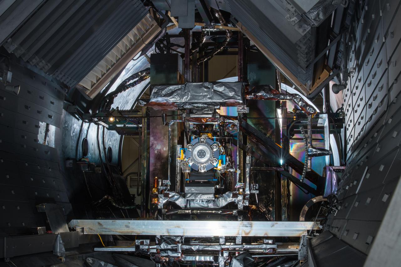
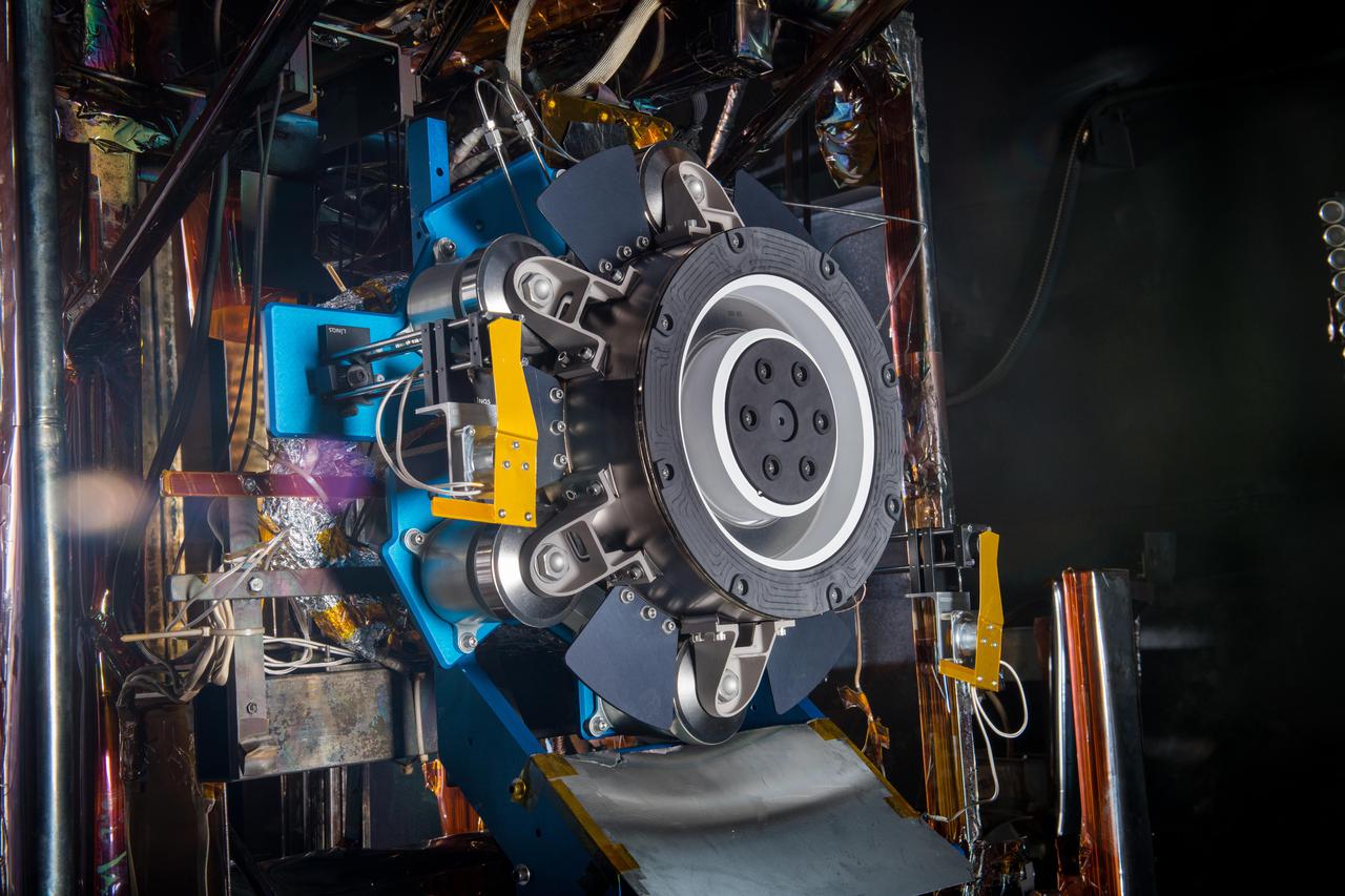
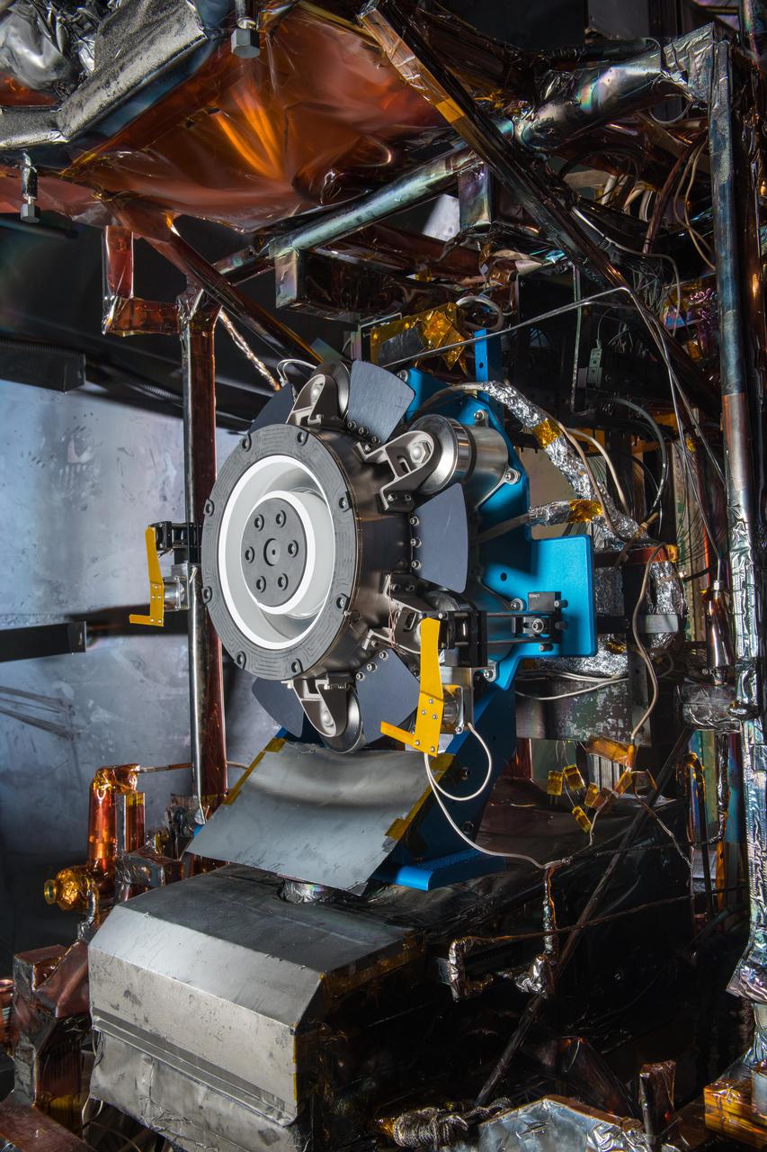
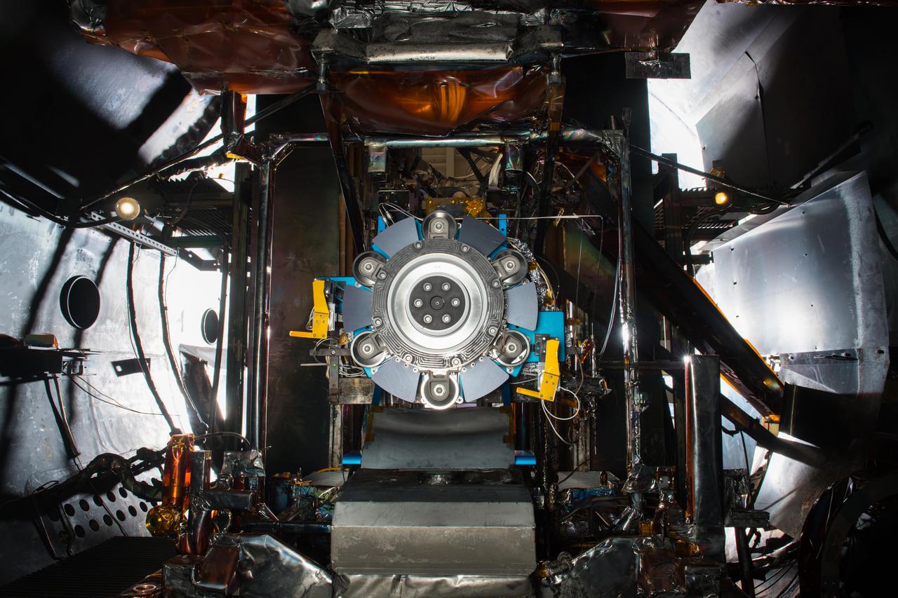
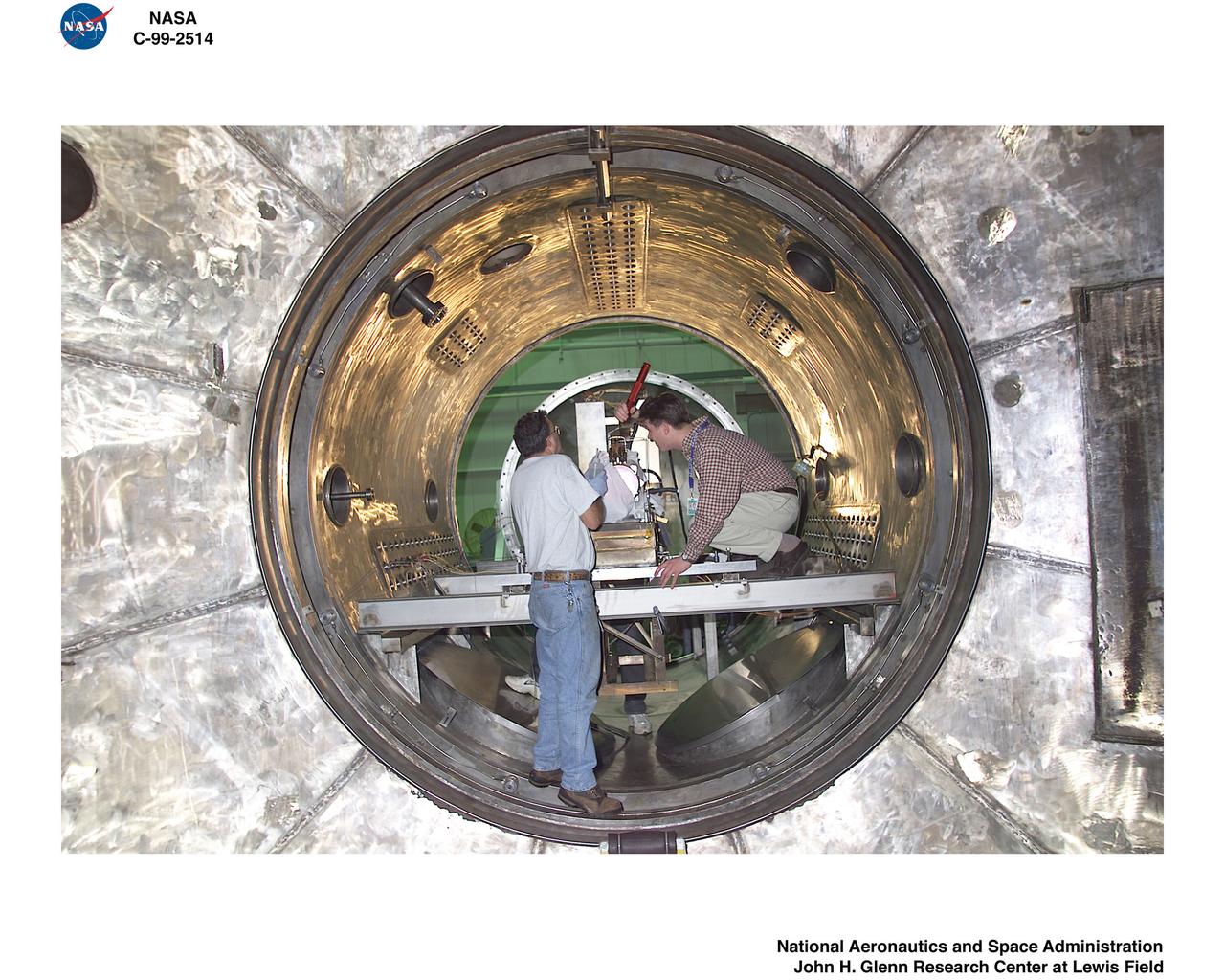
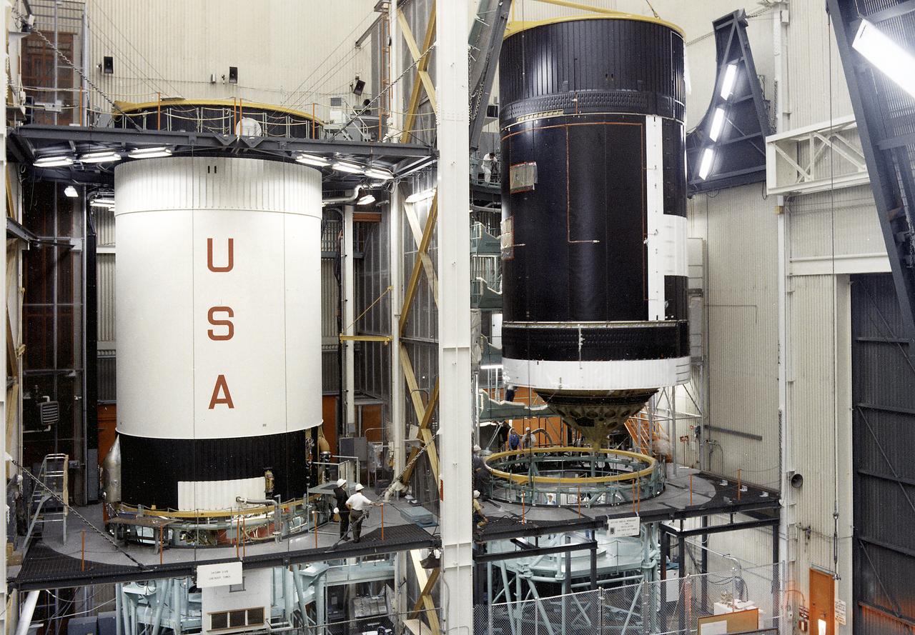
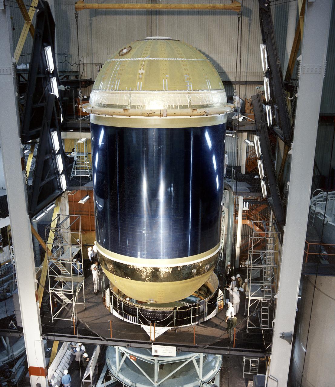
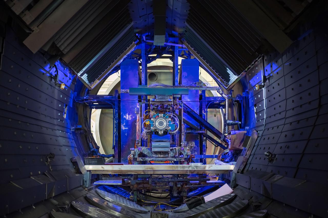
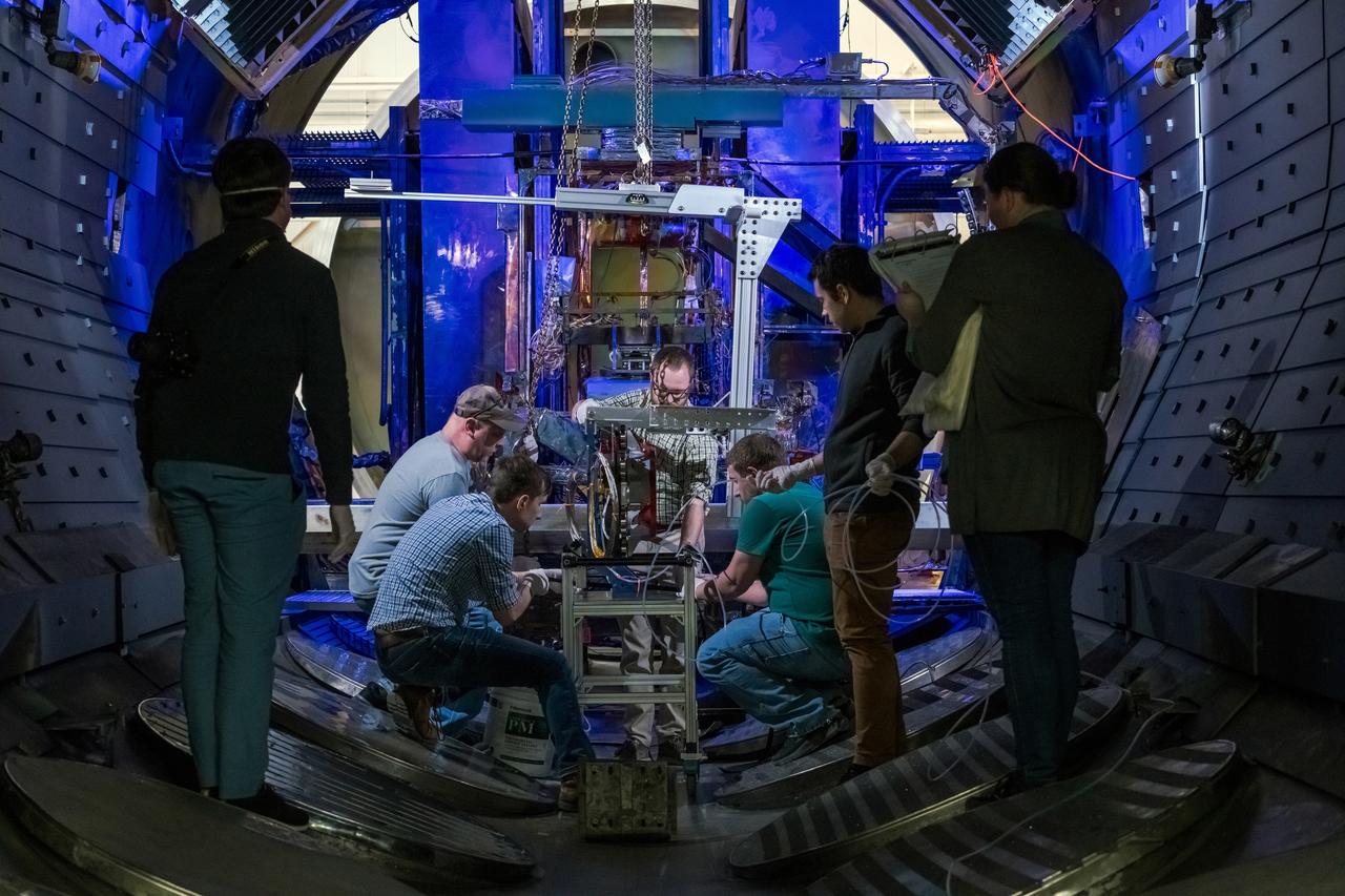
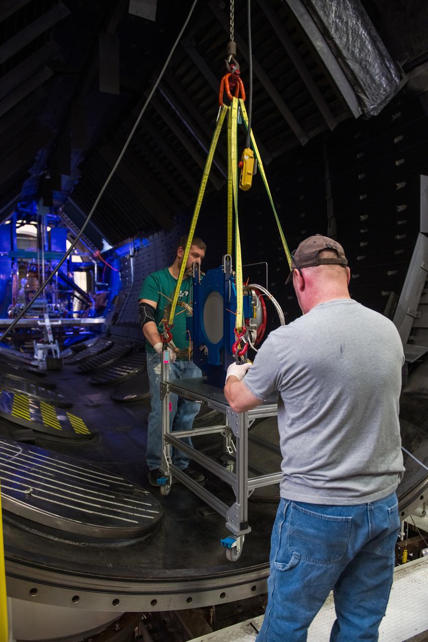
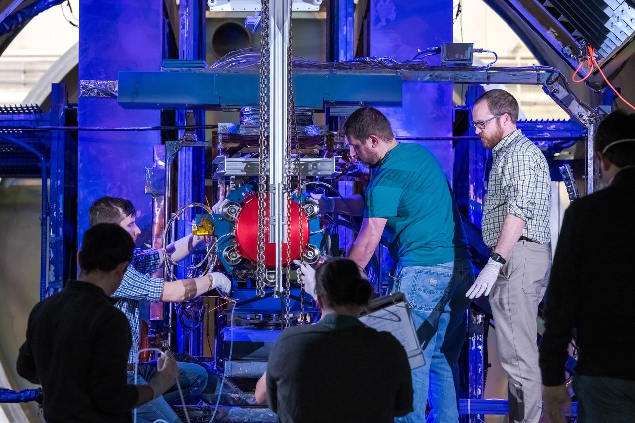
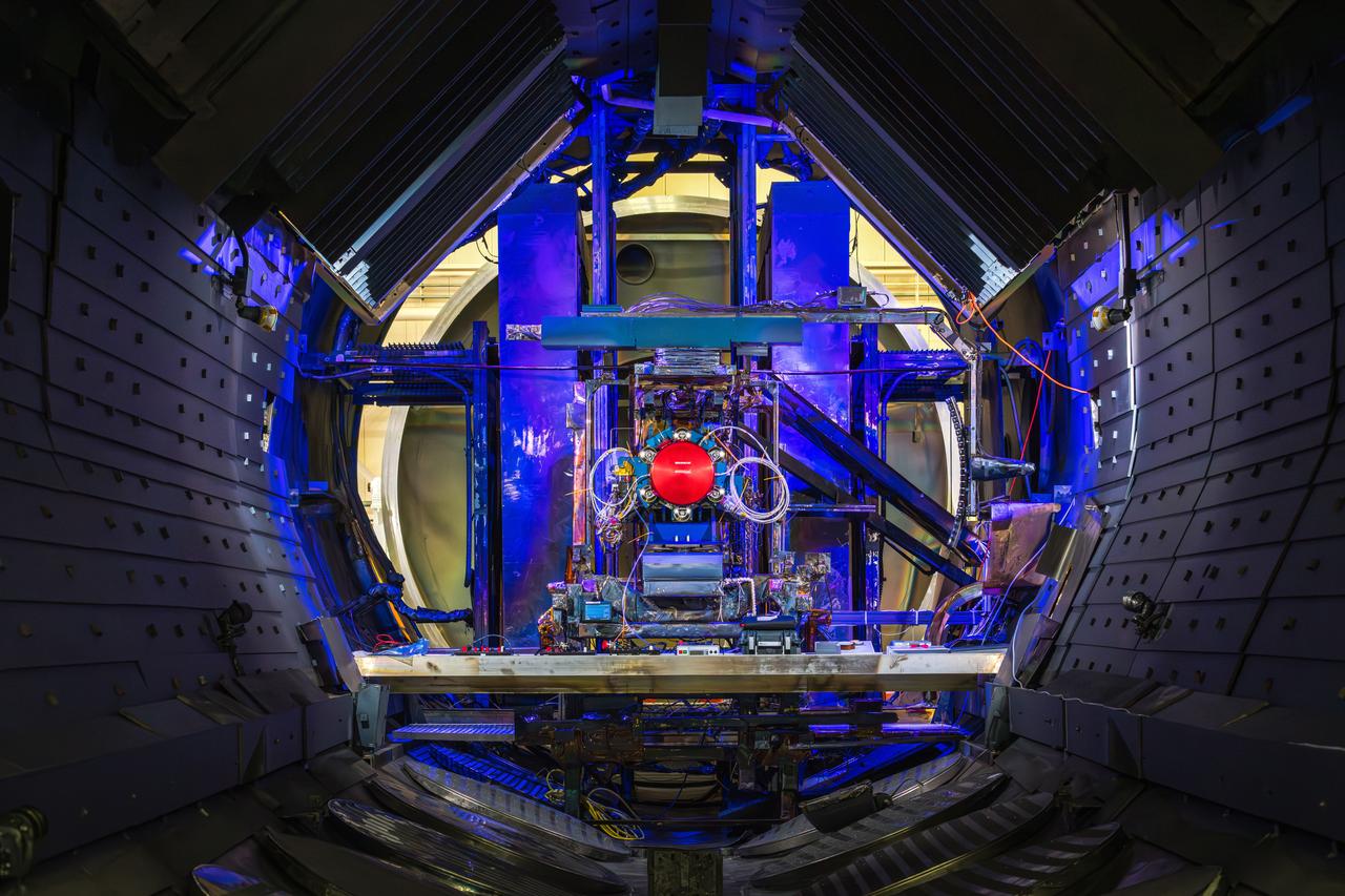
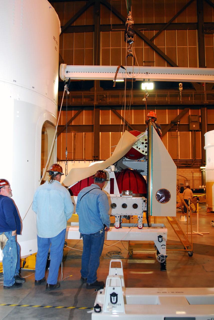
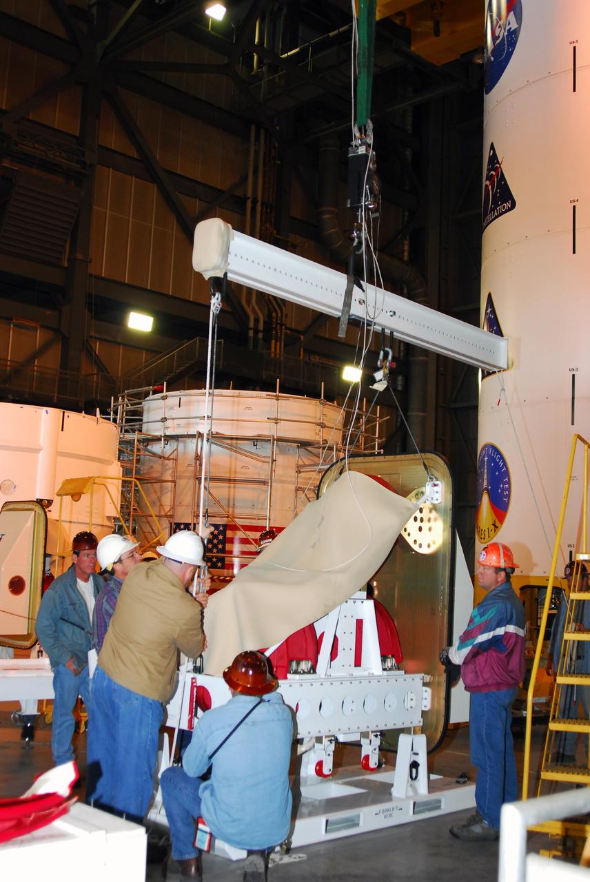
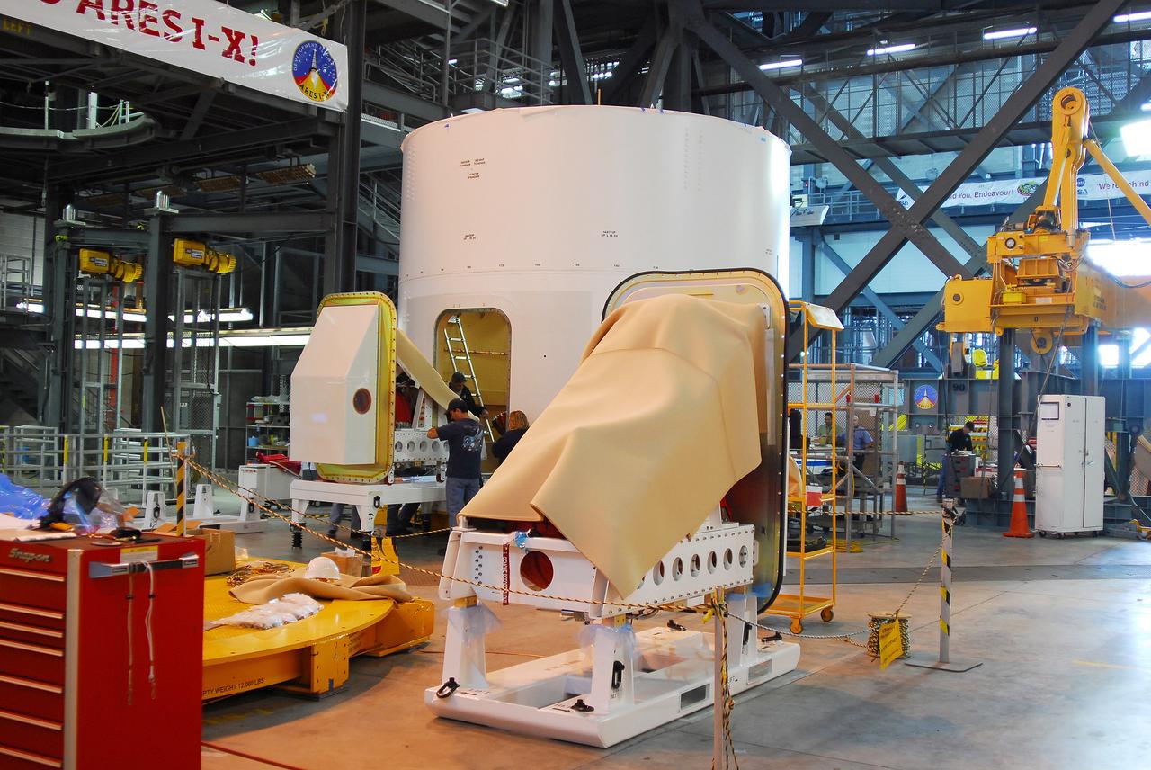
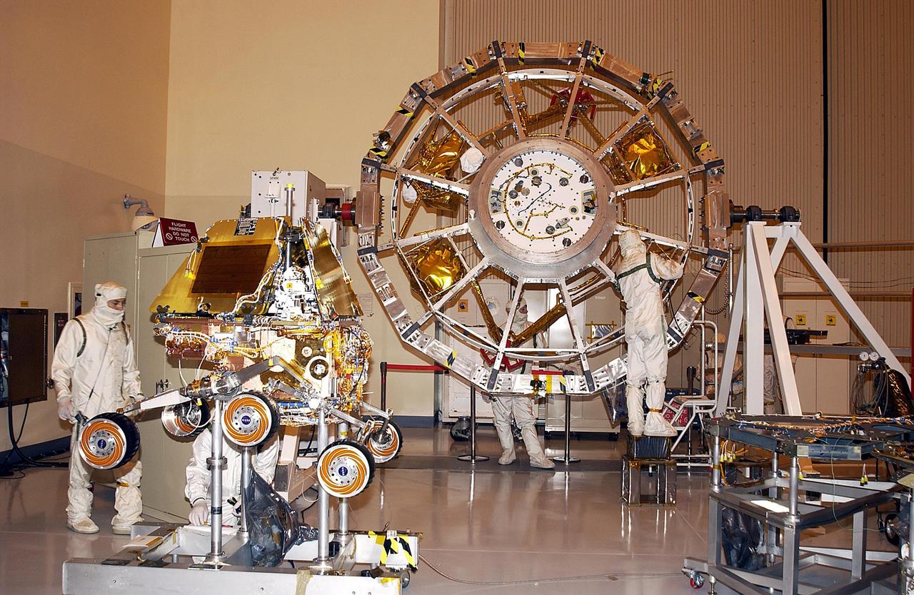
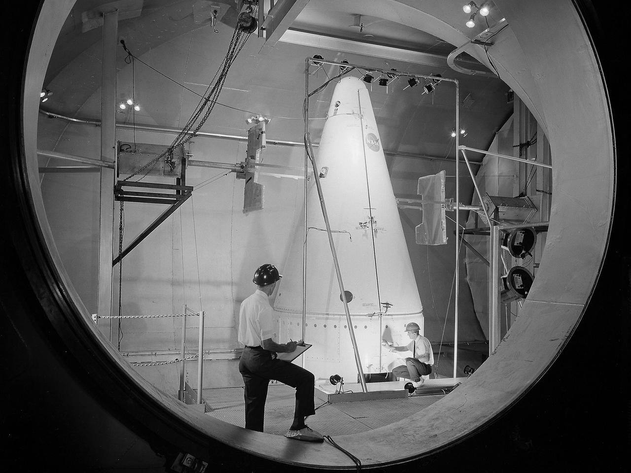
Shroud for the Surveyor Spacecraft in the Space Power Chambers