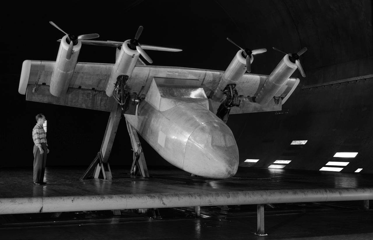
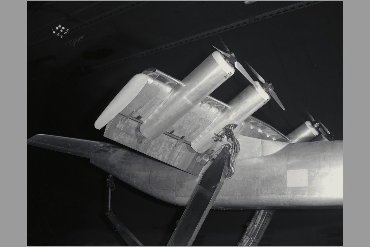
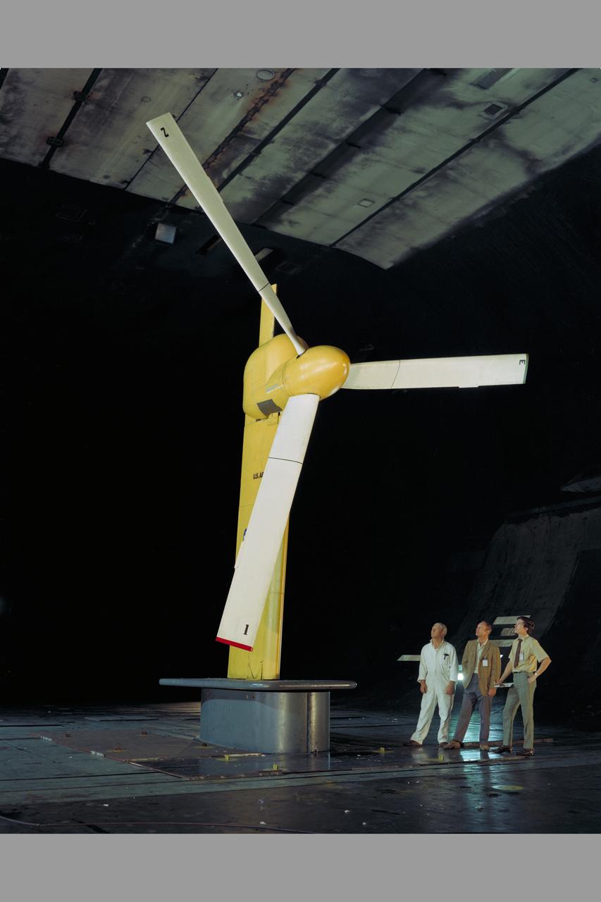
Investigation of a tilt-wing/propeller model with blowing flaps. 3/4 front view, tilt wing model, wing position = 0deg. C-123 fuselage, conventional struts, 4 props
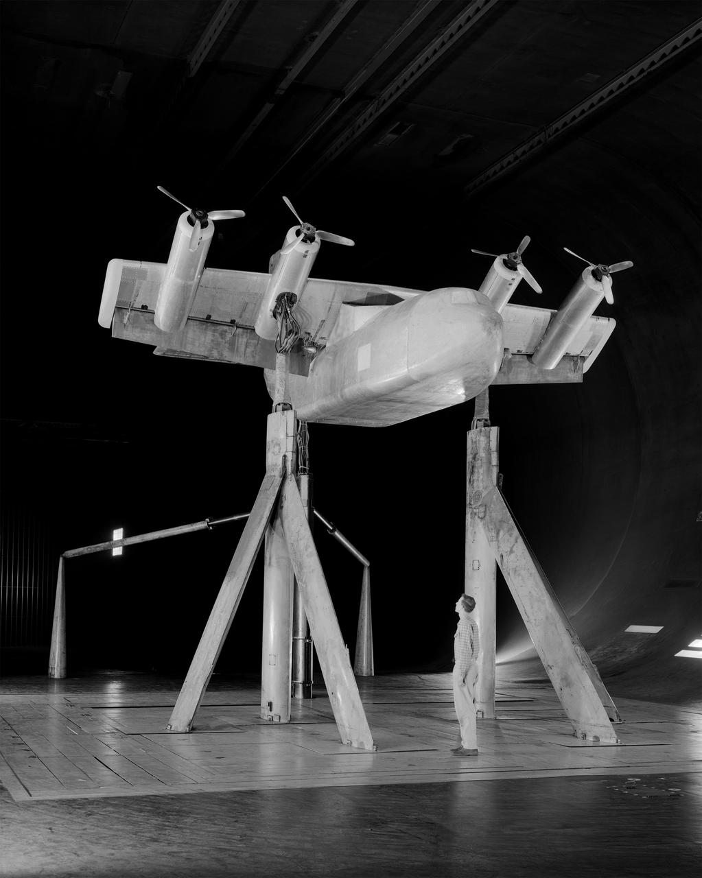
Tilt wing propeller model. 3/4 front view. 4 prop tilt wing nose down variable struts on ground board. Leo Holl, NASA Ames Engineer.
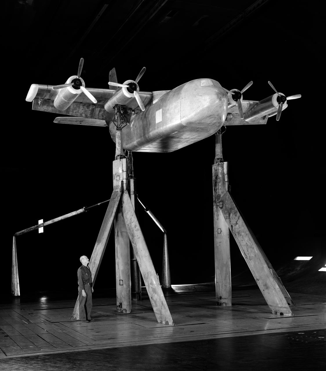
4 propeller Tilt Wing. Pictured with Tommy Wills wind tunnel mechanic in the 40x80 foot wind tunnel.
Tilt-Wing Propeller model with blowing flaps in 40x80ft w.t.
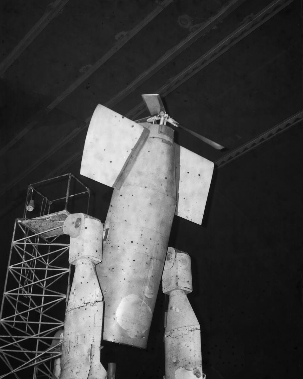
Vertol-76 Descent Test. Tilt Wing airplane prop rig at 80 deg. Angle of attack, in the 40x80 foot wind tunnel at NASA's Ames Research Center.
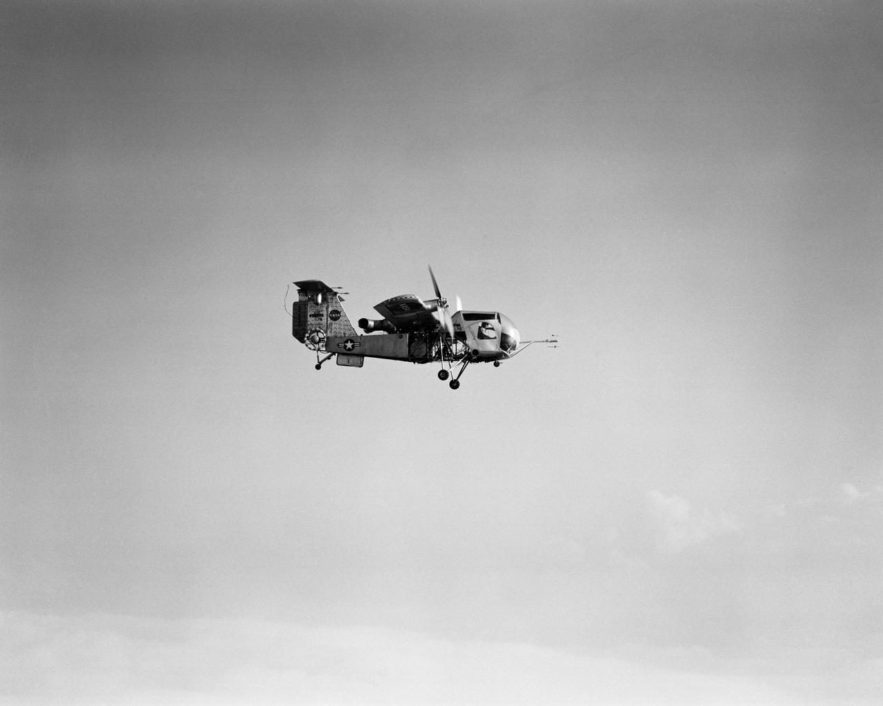
Vertol 76 Tilt Wing VTOL. Photographed 9/13/1960. Photograph published in Sixty Years of Aeronautical Research 1917-1977 By David A. Anderton, A NASA publication, Page 62.
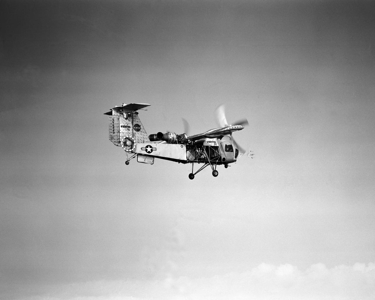
Vertol 76 Tilt Wing VTOL. Photographed 9/13/1960. Photograph published in Sixty Years of Aeronautical Research 1917-1977 By David A. Anderton, A NASA publication, Page 62.
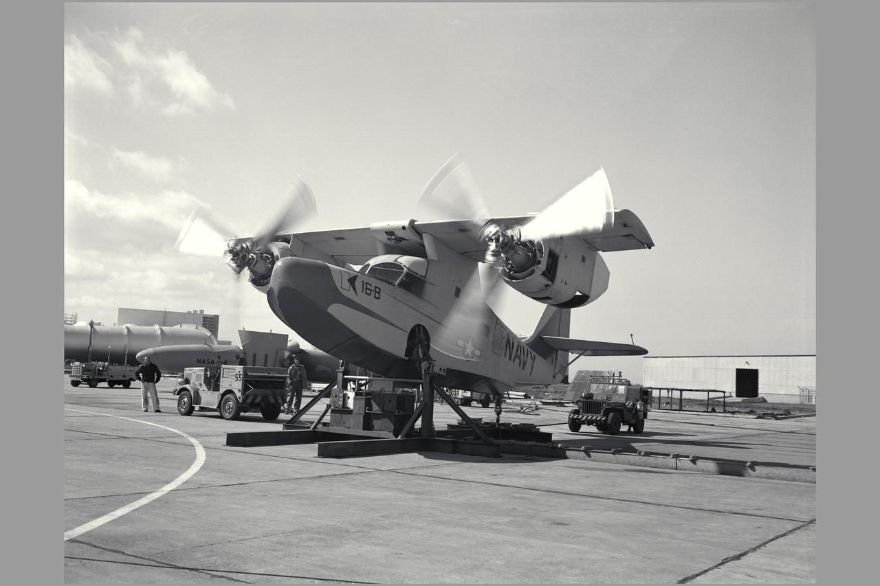
KAMAN K-16-B aircraft

Artwork: Bell Textron Co. Bell Textron Tilt Rotor Forward Swept Wing Configuration (Bell-029564 Swept Wing Tilt Rotor Concept)

Artwork: Bell Textron Co. Bell Textron Tilt Rotor folding swept wing and Forward Swept Wing Configurations (Bell-030355 Military High Speed Tilt Rotor)
Tilt Rotor and Tilt Wing Concepts: Bell-Boeing and Bell-Textron: showen is the NASA/ARMY/Navy XV-15

Tilt Rotor and Tilt Wing Concepts: Bell-Boeing and Bell-Textron: shown is the Multimission Transport Rescue

Tilt Rotor and Tilt Wing Concepts: Bell-Boeing and Bell-Textron: show is the NASA/ARMY/Navy XV-15
Avrocar in the shop of the 40x80 foot wind tunnel with the 4 prop tilt wing model in the back ground.
3/4 front view with wing tilted and flaps 0 degrees. Coin Airplane: Rotating cylinder flap applied.
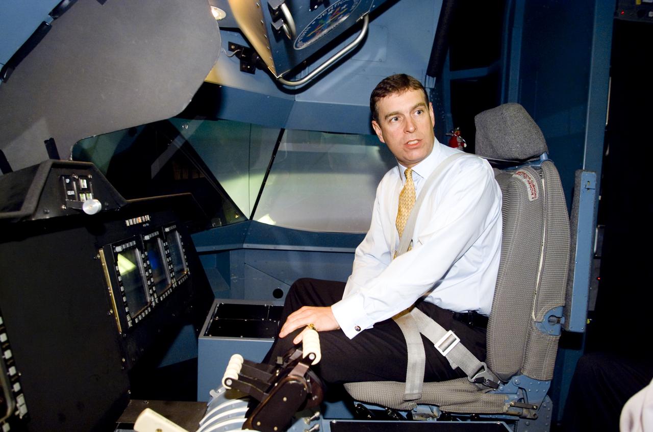
British Royalty visits Ames; Prince Andrew, Duke of York on tour. Seen here in the Vertical Motion Simulator in N-243 flying a tilt-wing simulation. (VMS)
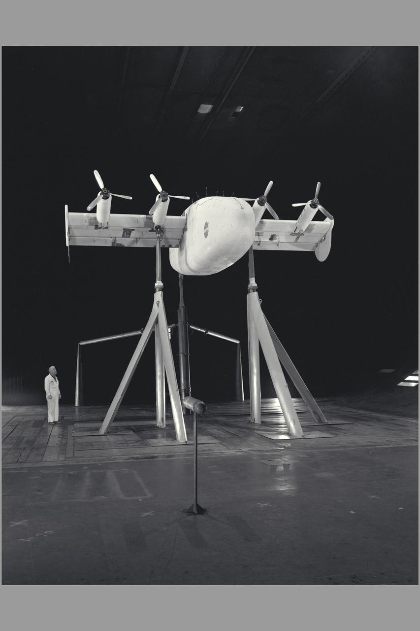
Rigid Tilt Rotor Research: Boeing 26-ft. diameter proprotor on semi-span wing in Ames Research Center 40x80ft w.t. (Photo by Ames photographer Lee Jones; composite of test results by Ames Graphics)
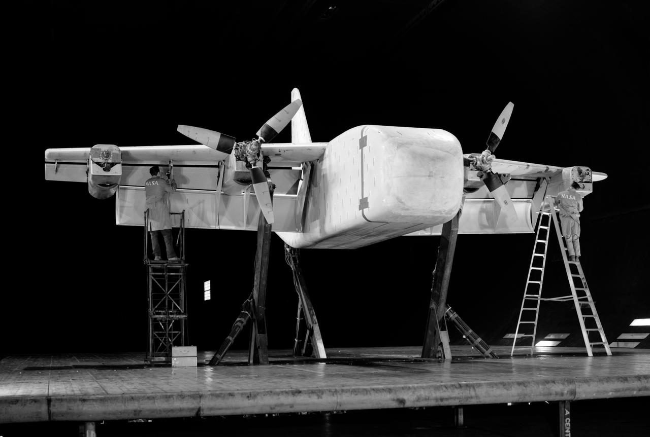
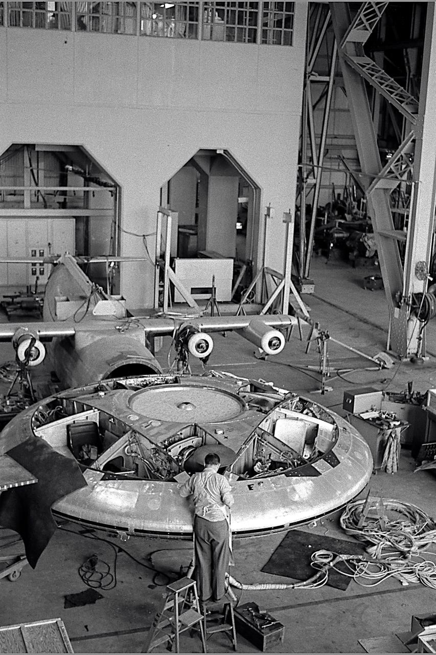
3/4 front right side only with Tim Wills on right and Charles Greco, mechanic. Large flaps on Variable height struts. XC-142 was a tri-service tiltwing experimental aircraft designed to investigate the operational suitability of vertical/short takeoff and landing (V/STOL) transports.
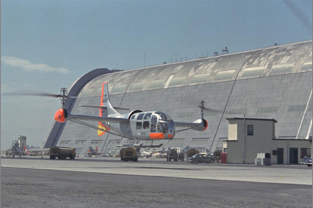
XV-3 HOVERING ON RAMP. Flight Test of Bell XV-3 Convertiplane. Bell VTOL tilt-rotor aircraft hovering along side Hangar One at Moffett Field. The XV-3 design combined a helicopter rotor and a wing. A 450 horsepower Pratt & Whitney piston engine drove the two rotors. The XV-3, first flown in 1955 , was the first tilt-rotor to achieve 100% tilting of rotors. The vehicle was underpowered, however, and could not hover out of ground effect. Note the large ventral fin, which was added to imrpove directional stability in cruse (Oct 1962)
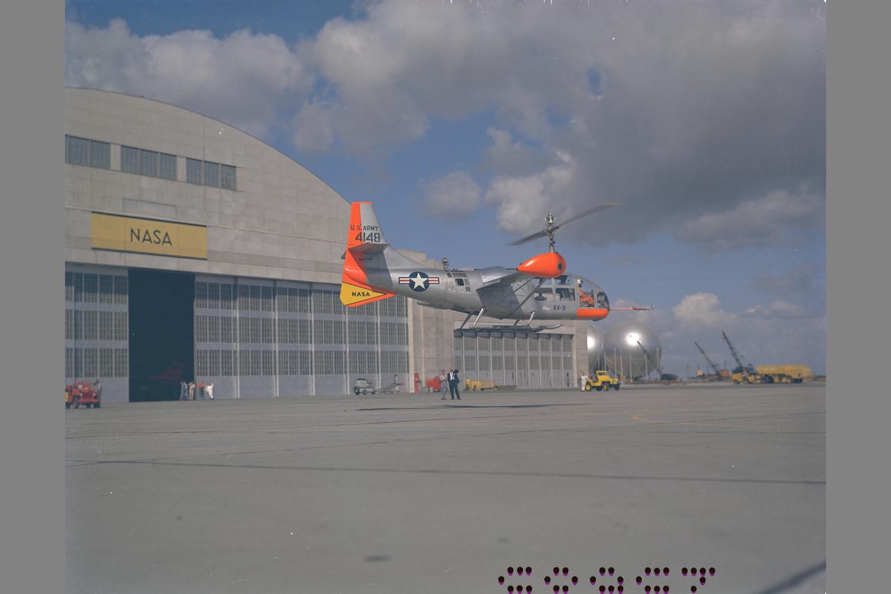
XV-3 HOVERING ON RAMP. Flight Test of Bell XV-3 Convertiplane. Bell VTOL tilt-rotor aircraft hovering in front of building N-211 at Moffett Field. The XV-3 design combined a helicopter rotor and a wing. A 450 horsepower Pratt & Whitney piston engine drove the two rotors. The XV-3, first flown in 1955 , was the first tilt-rotor to achieve 100% tilting of rotors. The vehicle was underpowered, however, and could not hover out of ground effect. Note the large ventral fin, which was added to imrpove directional stability in cruse (Oct 1962)
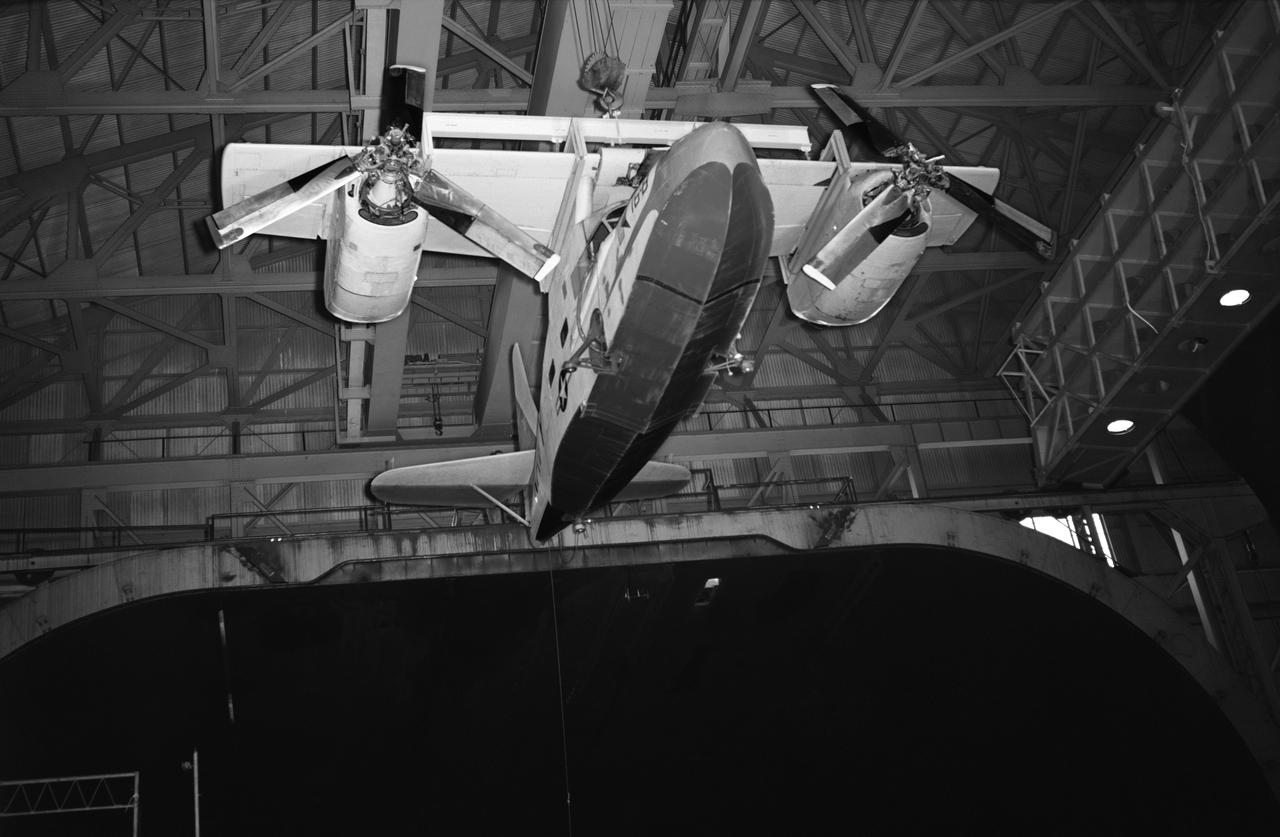
Test No. 175 Kaman K-16 being lowered into the 40x80 foot wind tunnel at NASA's Ames Research Center, viewed from the front. Kaman K-16B was an experimental tilt wing aircraft, it used the fuselage of a JRF-5 and was powered by two General Electric YT58-GE-2A engines.
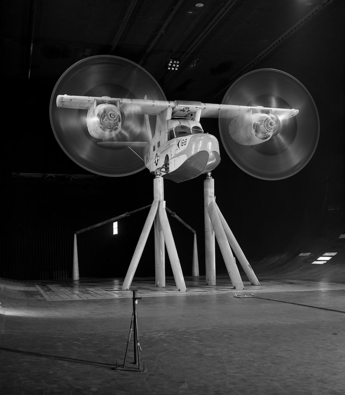
Test No. 175 Kaman K-16 in 40x80 Foot Wind Tunnel at Ames Research Center. Kaman K-16B was an experimental tilt wing aircraft, it used the fuselage of a JRF-5 and was powered by two General Electric YT58-GE-2A engines.
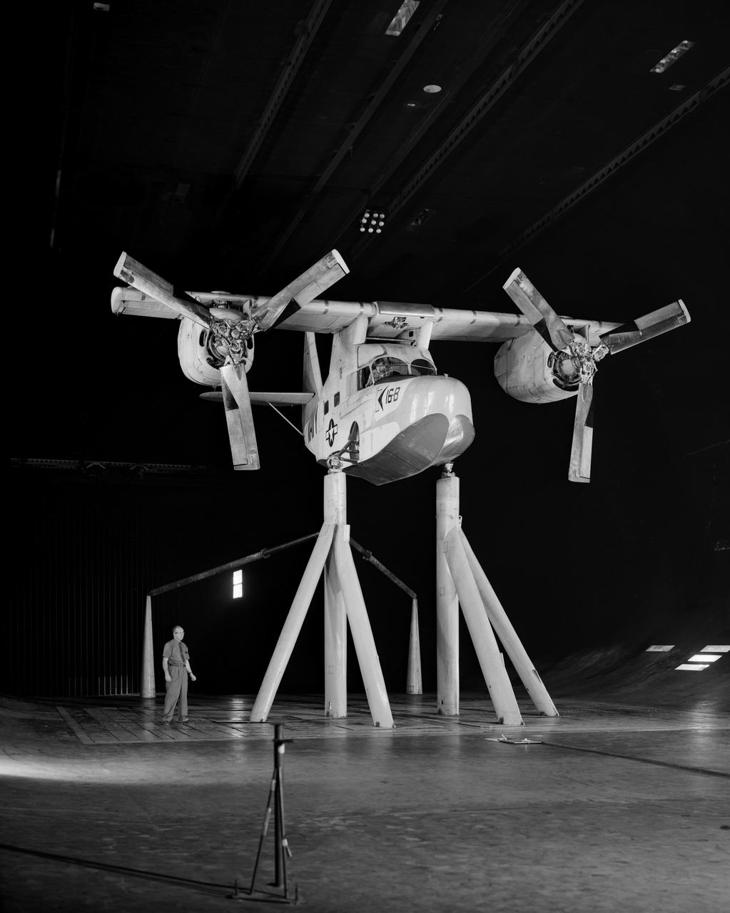
Test No. 175 Kaman K-16 in 40x80 Foot Wind Tunnel at Ames Research Center. Pictured with two Kaman employees. 3/4 Front view of Airplane. Kaman K-16B was an experimental tilt wing aircraft, it used the fuselage of a JRF-5 and was powered by two General Electric YT58-GE-2A engines.
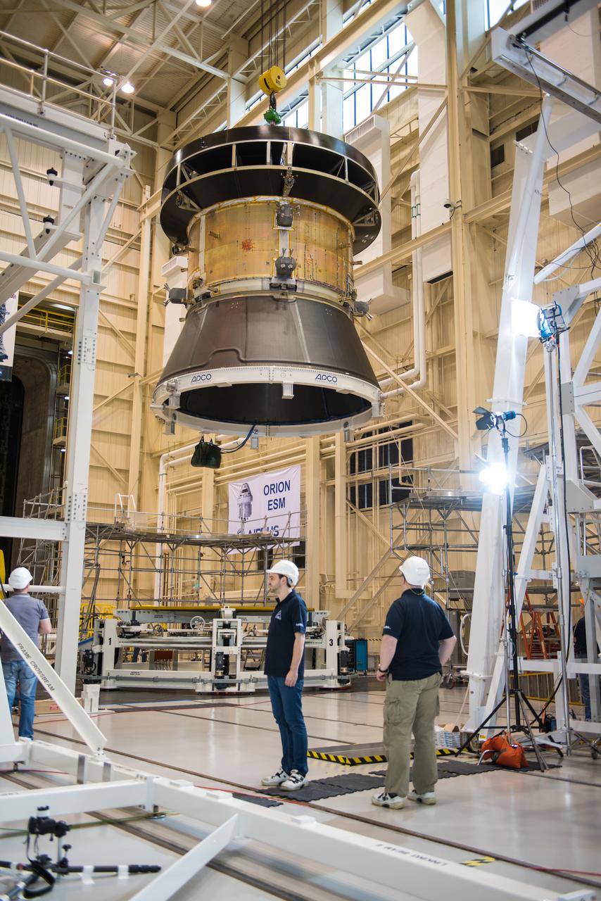
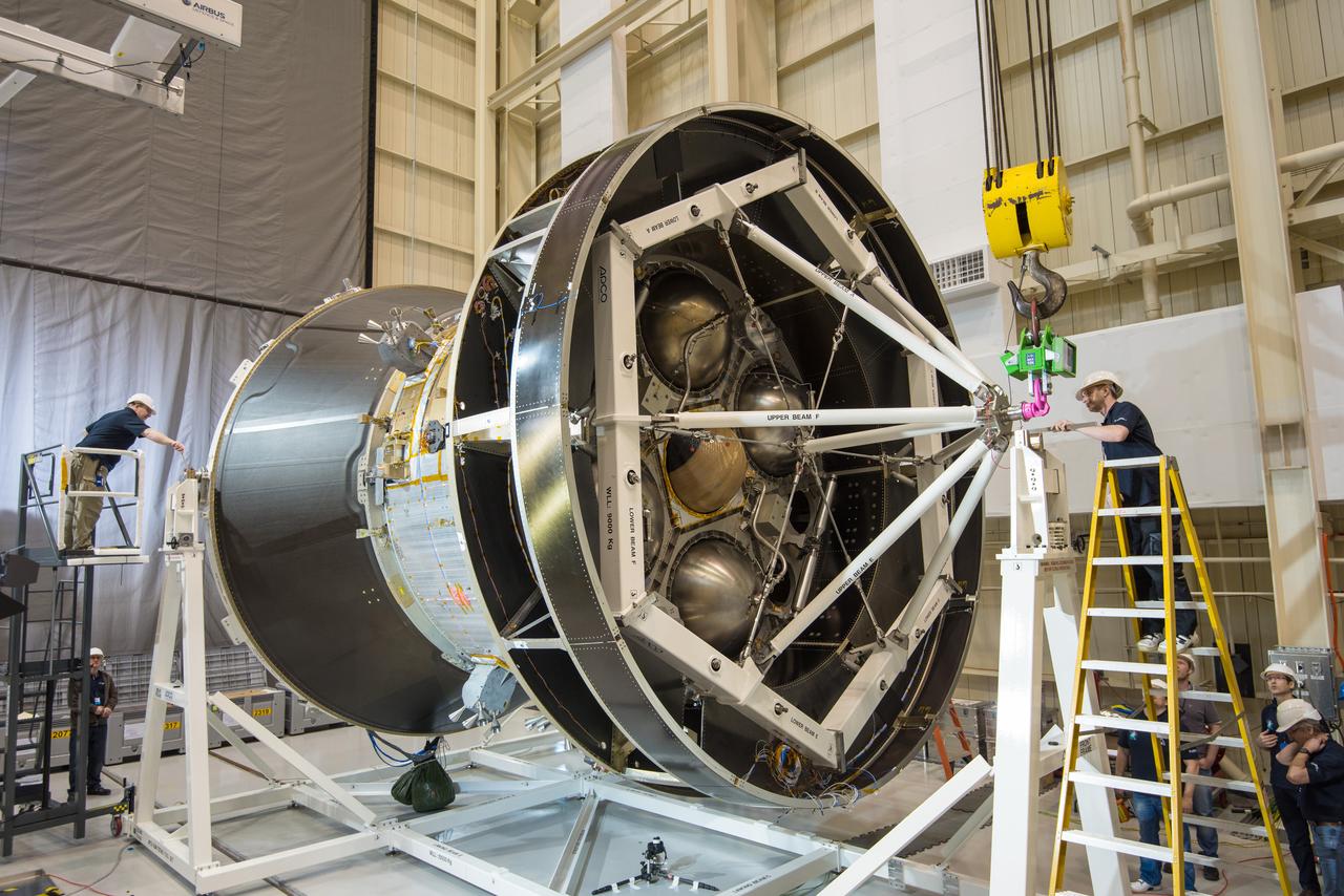
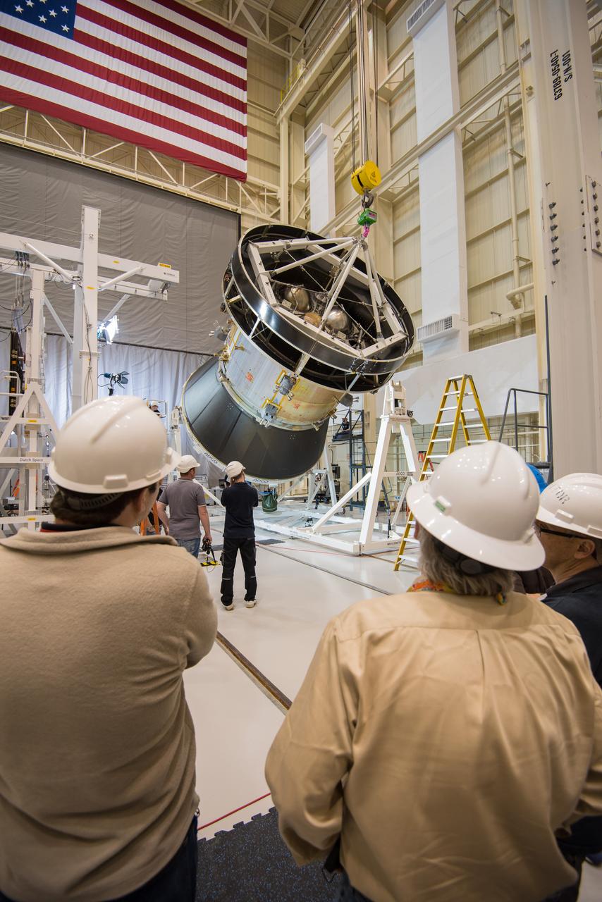
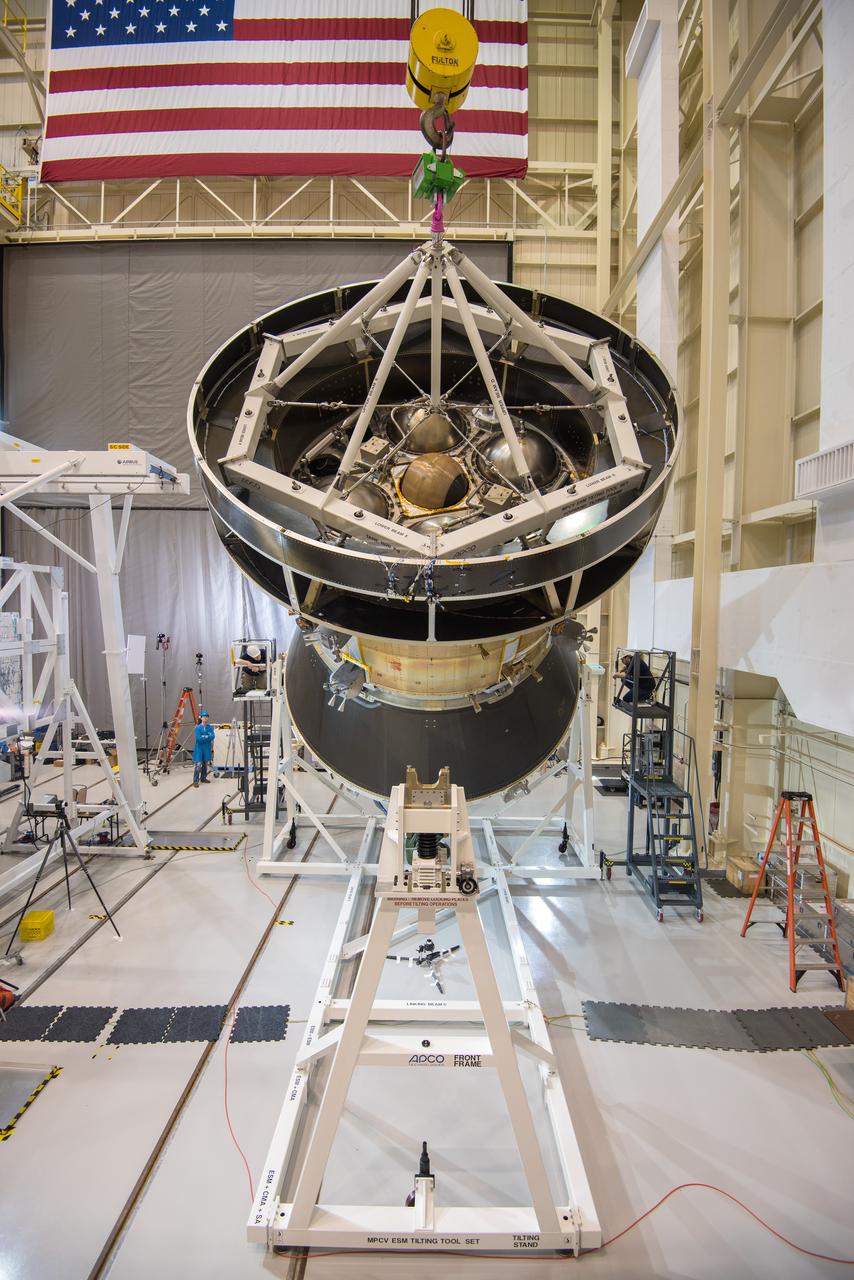
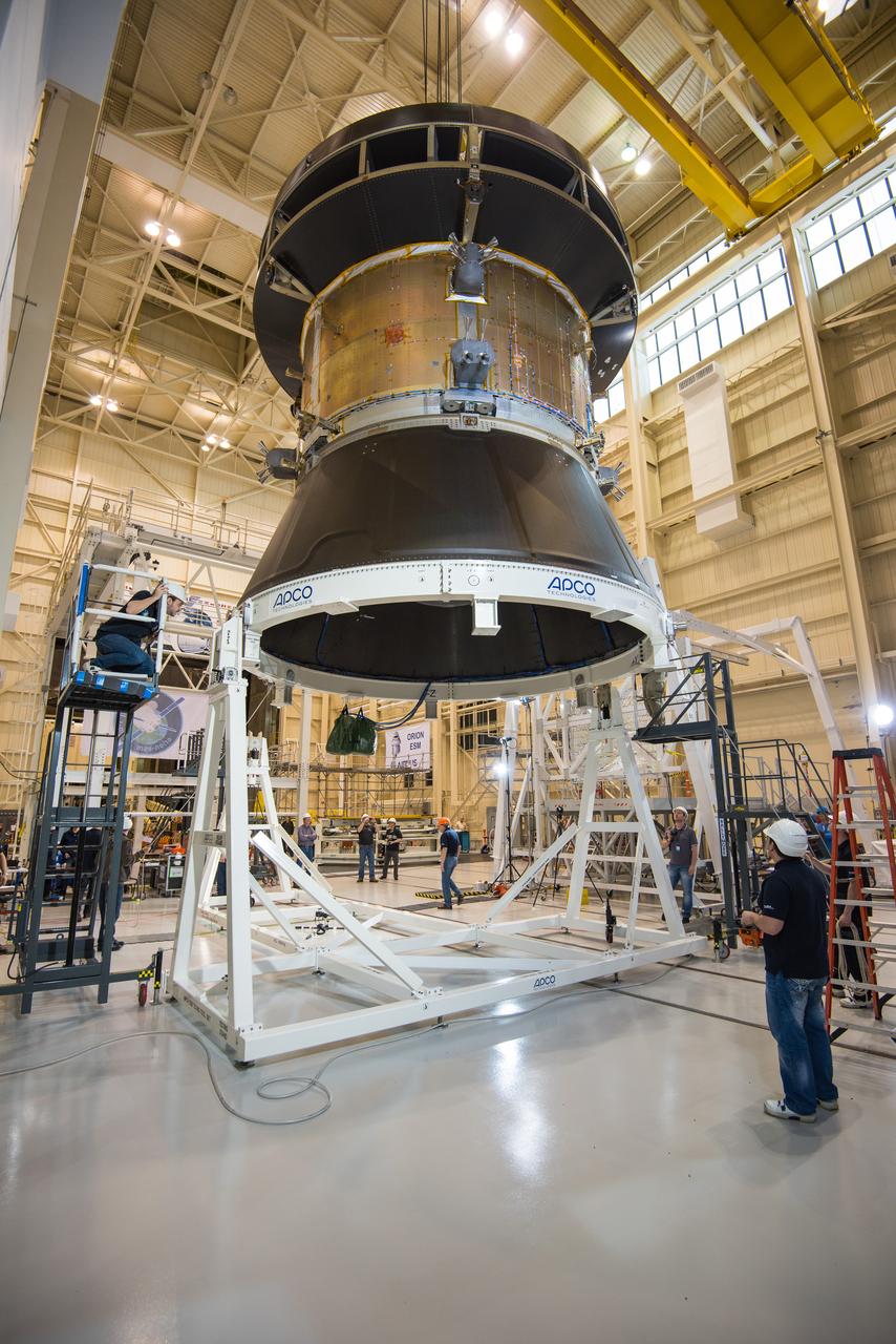
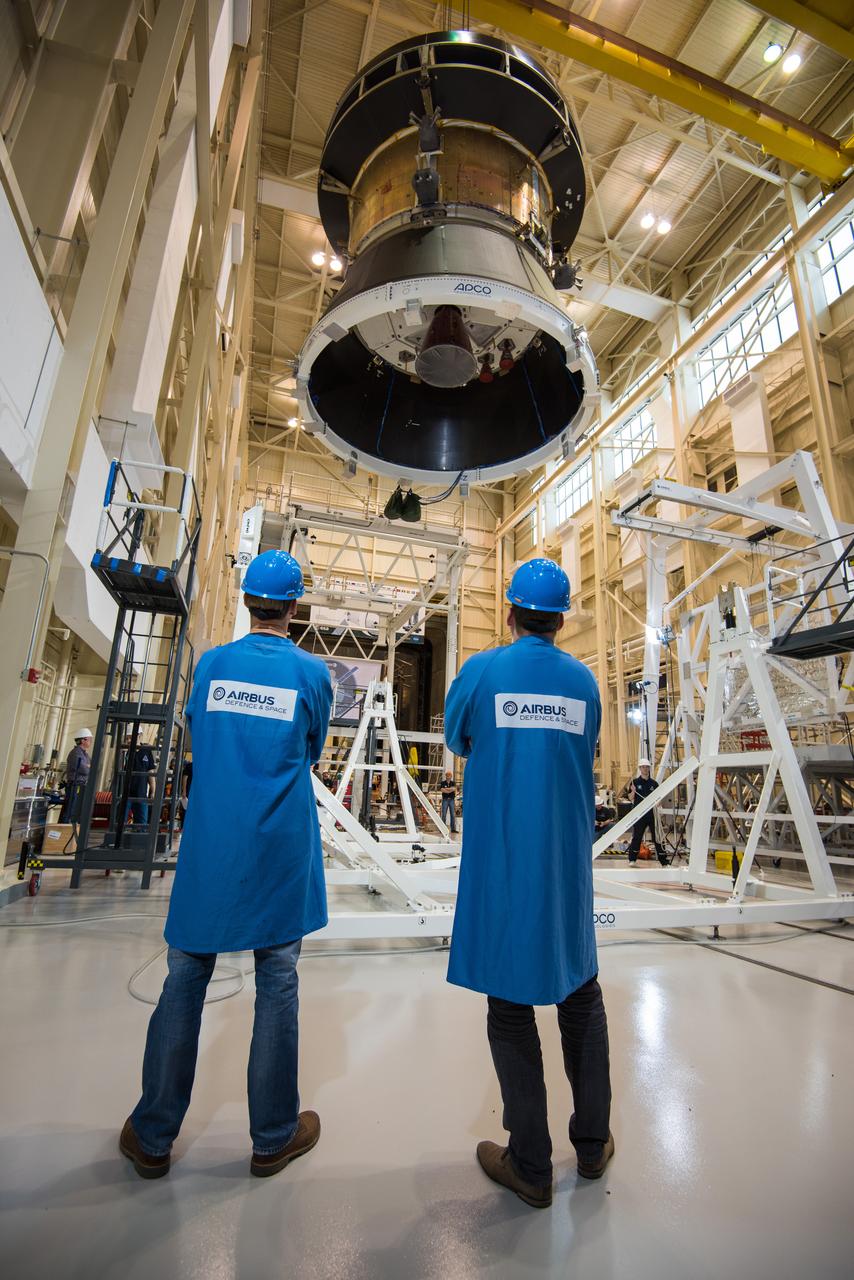
Engineers and technicians at NASA Glenn's Plum Brook Station in Sandusky, Ohio, are preparing for the first major test in the campaign to verify the structural integrity of Orion’s service module for Artemis I, the spacecraft’s first flight atop the agency’s Space Launch System (SLS) rocket. Orion’s service module, which will power and propel the vehicle and supply it with air and water, is being provided by ESA and built by Airbus Defence and Space. The solar array wing deployment test will verify that the qualification model wing unfurls as expected. On Saturday, Feb. 20, an international team of engineers and technicians lifted and tilted the service module test article -- which includes structural representations of the service module, crew module adapter, and spacecraft adapter -- to a 90 degree angle to position it for the deployment test of one of Orion’s four solar arrays. The next step in preparation for the test is attaching the solar array before the Feb. 29 deployment test. This is the first in a series of crucial tests to verify the service module’s structural integrity and ability to withstand the dynamic launch environment atop the SLS rocket.
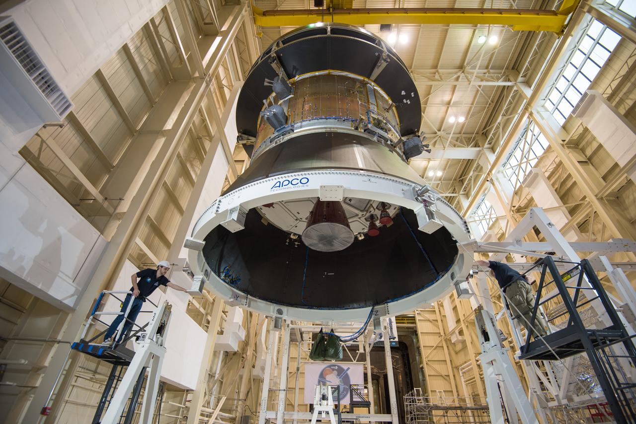
Engineers and technicians at NASA Glenn's Plum Brook Station in Sandusky, Ohio, are preparing for the first major test in the campaign to verify the structural integrity of Orion’s service module for Artemis I, the spacecraft’s first flight atop the agency’s Space Launch System (SLS) rocket. Orion’s service module, which will power and propel the vehicle and supply it with air and water, is being provided by ESA and built by Airbus Defence and Space. The solar array wing deployment test will verify that the qualification model wing unfurls as expected. On Saturday, Feb. 20, an international team of engineers and technicians lifted and tilted the service module test article -- which includes structural representations of the service module, crew module adapter, and spacecraft adapter -- to a 90 degree angle to position it for the deployment test of one of Orion’s four solar arrays. The next step in preparation for the test is attaching the solar array before the Feb. 29 deployment test. This is the first in a series of crucial tests to verify the service module’s structural integrity and ability to withstand the dynamic launch environment atop the SLS rocket.
Engineers and technicians at NASA Glenn's Plum Brook Station in Sandusky, Ohio, are preparing for the first major test in the campaign to verify the structural integrity of Orion’s service module for Artemis I, the spacecraft’s first flight atop the agency’s Space Launch System (SLS) rocket. Orion’s service module, which will power and propel the vehicle and supply it with air and water, is being provided by ESA and built by Airbus Defence and Space. The solar array wing deployment test will verify that the qualification model wing unfurls as expected. On Saturday, Feb. 20, an international team of engineers and technicians lifted and tilted the service module test article -- which includes structural representations of the service module, crew module adapter, and spacecraft adapter -- to a 90 degree angle to position it for the deployment test of one of Orion’s four solar arrays. The next step in preparation for the test is attaching the solar array before the Feb. 29 deployment test. This is the first in a series of crucial tests to verify the service module’s structural integrity and ability to withstand the dynamic launch environment atop the SLS rocket.
Engineers and technicians at NASA Glenn's Plum Brook Station in Sandusky, Ohio, are preparing for the first major test in the campaign to verify the structural integrity of Orion’s service module for Artemis I, the spacecraft’s first flight atop the agency’s Space Launch System (SLS) rocket. Orion’s service module, which will power and propel the vehicle and supply it with air and water, is being provided by ESA and built by Airbus Defence and Space. The solar array wing deployment test will verify that the qualification model wing unfurls as expected. On Saturday, Feb. 20, an international team of engineers and technicians lifted and tilted the service module test article -- which includes structural representations of the service module, crew module adapter, and spacecraft adapter -- to a 90 degree angle to position it for the deployment test of one of Orion’s four solar arrays. The next step in preparation for the test is attaching the solar array before the Feb. 29 deployment test. This is the first in a series of crucial tests to verify the service module’s structural integrity and ability to withstand the dynamic launch environment atop the SLS rocket.
Engineers and technicians at NASA Glenn's Plum Brook Station in Sandusky, Ohio, are preparing for the first major test in the campaign to verify the structural integrity of Orion’s service module for Artemis I, the spacecraft’s first flight atop the agency’s Space Launch System (SLS) rocket. Orion’s service module, which will power and propel the vehicle and supply it with air and water, is being provided by ESA and built by Airbus Defence and Space. The solar array wing deployment test will verify that the qualification model wing unfurls as expected. On Saturday, Feb. 20, an international team of engineers and technicians lifted and tilted the service module test article -- which includes structural representations of the service module, crew module adapter, and spacecraft adapter -- to a 90 degree angle to position it for the deployment test of one of Orion’s four solar arrays. The next step in preparation for the test is attaching the solar array before the Feb. 29 deployment test. This is the first in a series of crucial tests to verify the service module’s structural integrity and ability to withstand the dynamic launch environment atop the SLS rocket.
Engineers and technicians at NASA Glenn's Plum Brook Station in Sandusky, Ohio, are preparing for the first major test in the campaign to verify the structural integrity of Orion’s service module for Artemis I, the spacecraft’s first flight atop the agency’s Space Launch System (SLS) rocket. Orion’s service module, which will power and propel the vehicle and supply it with air and water, is being provided by ESA and built by Airbus Defence and Space. The solar array wing deployment test will verify that the qualification model wing unfurls as expected. On Saturday, Feb. 20, an international team of engineers and technicians lifted and tilted the service module test article -- which includes structural representations of the service module, crew module adapter, and spacecraft adapter -- to a 90 degree angle to position it for the deployment test of one of Orion’s four solar arrays. The next step in preparation for the test is attaching the solar array before the Feb. 29 deployment test. This is the first in a series of crucial tests to verify the service module’s structural integrity and ability to withstand the dynamic launch environment atop the SLS rocket.
Engineers and technicians at NASA Glenn's Plum Brook Station in Sandusky, Ohio, are preparing for the first major test in the campaign to verify the structural integrity of Orion’s service module for Artemis I, the spacecraft’s first flight atop the agency’s Space Launch System (SLS) rocket. Orion’s service module, which will power and propel the vehicle and supply it with air and water, is being provided by ESA and built by Airbus Defence and Space. The solar array wing deployment test will verify that the qualification model wing unfurls as expected. On Saturday, Feb. 20, an international team of engineers and technicians lifted and tilted the service module test article -- which includes structural representations of the service module, crew module adapter, and spacecraft adapter -- to a 90 degree angle to position it for the deployment test of one of Orion’s four solar arrays. The next step in preparation for the test is attaching the solar array before the Feb. 29 deployment test. This is the first in a series of crucial tests to verify the service module’s structural integrity and ability to withstand the dynamic launch environment atop the SLS rocket.

Engineers and technicians at NASA Glenn's Plum Brook Station in Sandusky, Ohio, are preparing for the first major test in the campaign to verify the structural integrity of Orion’s service module for Artemis I, the spacecraft’s first flight atop the agency’s Space Launch System (SLS) rocket. Orion’s service module, which will power and propel the vehicle and supply it with air and water, is being provided by ESA and built by Airbus Defence and Space. The solar array wing deployment test will verify that the qualification model wing unfurls as expected. On Saturday, Feb. 20, an international team of engineers and technicians lifted and tilted the service module test article -- which includes structural representations of the service module, crew module adapter, and spacecraft adapter -- to a 90 degree angle to position it for the deployment test of one of Orion’s four solar arrays. The next step in preparation for the test is attaching the solar array before the Feb. 29 deployment test. This is the first in a series of crucial tests to verify the service module’s structural integrity and ability to withstand the dynamic launch environment atop the SLS rocket.

NASA employees Broderic J. Gonzalez, left, and David W. Shank, right, install pieces of a 7-foot wing model in preparation for testing in the 14-by-22-Foot Subsonic Wind Tunnel at NASA's Langley Research Center in Hampton, Virginia, in May 2025. The lessons learned from this testing will be shared with the public to support advanced air mobility aircraft development.

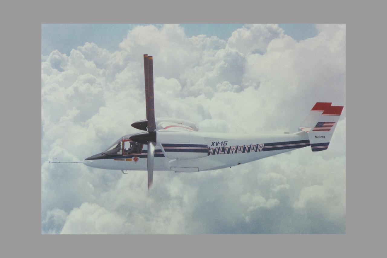
The XV-15 tilt rotor ships #1 and #2 parked on the NASA Dryden Flight Research Center ramp. The XV-15s, manufactured by Bell, were involved in limited research at Dryden in 1980 and 1981. The development of the XV-15 Tiltrotor research aircraft was initiated in 1973 with joint Army/NASA funding as a "proof of concept", or "technology demonstrator" program, with two aircraft being built by Bell Helicopter Textron (BHT) in 1977. The aircraft are powered by twin Lycoming T-53 turboshaft engines that are connected by a cross-shaft and drive three-bladed, 25 ft diameter metal rotors (the size extensively tested in a wind tunnel). The engines and main transmissions are located in wingtip nacelles to minimize the operational loads on the cross-shaft system and, with the rotors, tilt as a single unit. For takeoff, the proprotors and their engines are used in the straight-up position where the thrust is directed downward. The XV-15 then climbs vertically into the air like a helicopter. In this VTOL mode, the vehicle can lift off and hover for approximately one hour. Once off the ground, the XV-15 has the ability to fly in one of two different modes. It can fly as a helicopter, in the partially converted airplane mode. The XV-15 can also then convert from the helicopter mode to the airplane mode. This is accomplished by continuous rotation of the proprotors from the helicopter rotor position to the conventional airplane propeller position. During the ten to fifteen second conversion period, the aircraft speed increases and lift is transferred from the rotors to the wing. To land, the proprotors are rotated up to the helicopter rotor position and flown as a helicopter to a vertical landing.