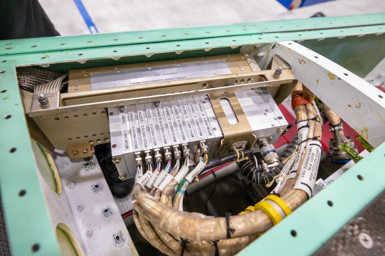
Here is a closeup of some of the X-59’s wiring and instrumentation system. Displayed here is the remote instrumentation encoder, which can be found in the wing of the aircraft. This encoder communicates with the plane’s other instrumentation systems like pressure and temperature sensors within the X-59.
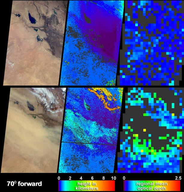
Clear skies on April 11, 2004 top panels contrast strongly with the dust storm that swept across Iraq and Saudi Arabia on May 13 bottom panels as seen by NASA Terra spacecraft.
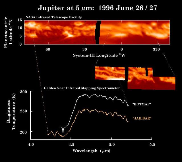
These observations of Jupiter equator in thermal heat emission were made by NASA Infrared Telescope Facility top panel within hours of the Near-Infrared Mapping Spectrometer NIMS instrument image middle inset and the spectra bottom.
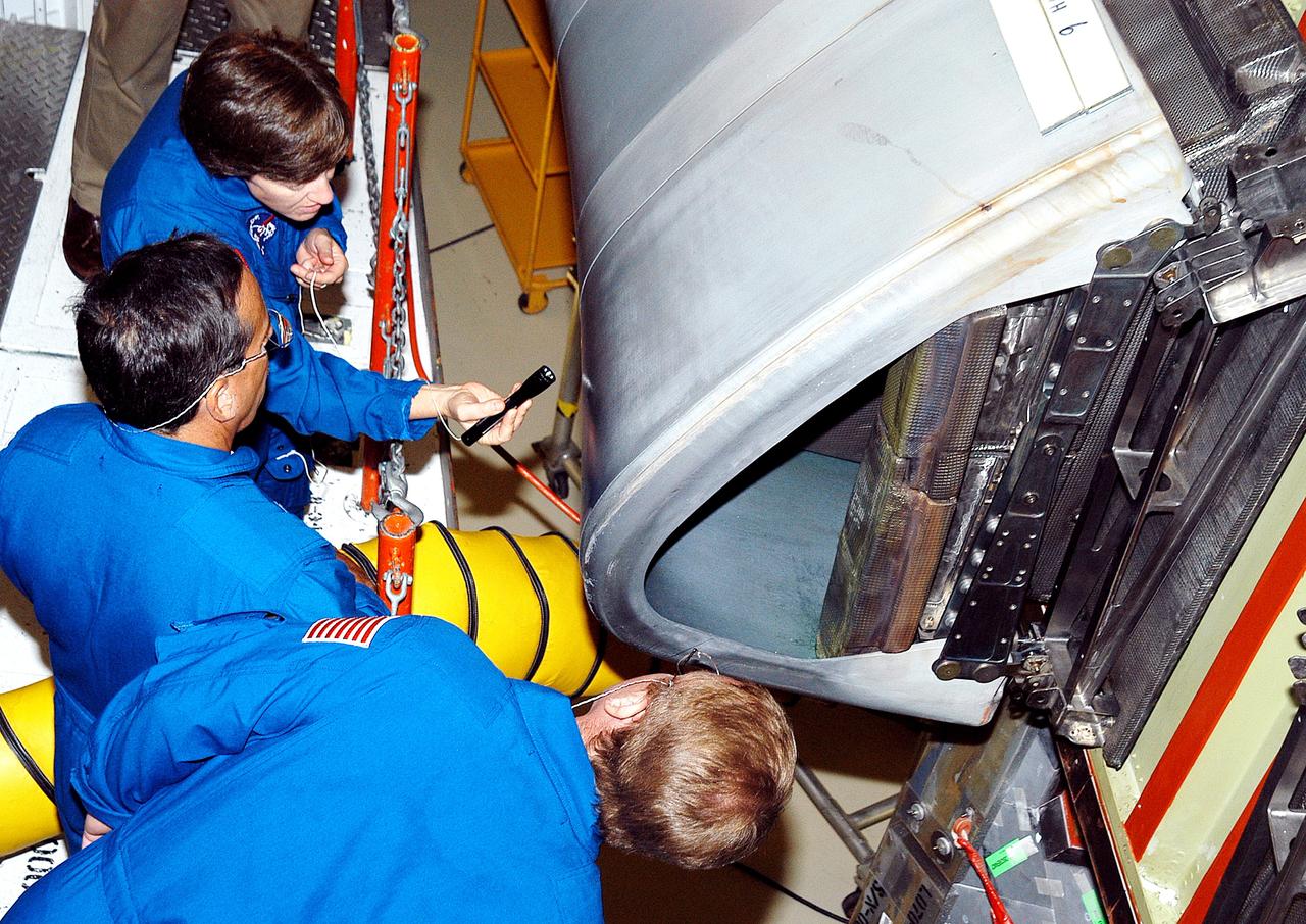
KENNEDY SPACE CENTER, FLA. - In the Orbiter Processing Facility, STS-114 crew members look at the reinforced carbon-carbon panels on the wing of Atlantis. From top to bottom are Commander Eileen Collins and Mission Specialists Charles Camarda and Andrew Thomas. The STS-114 crew is at KSC to take part in crew equipment and orbiter familiarization.
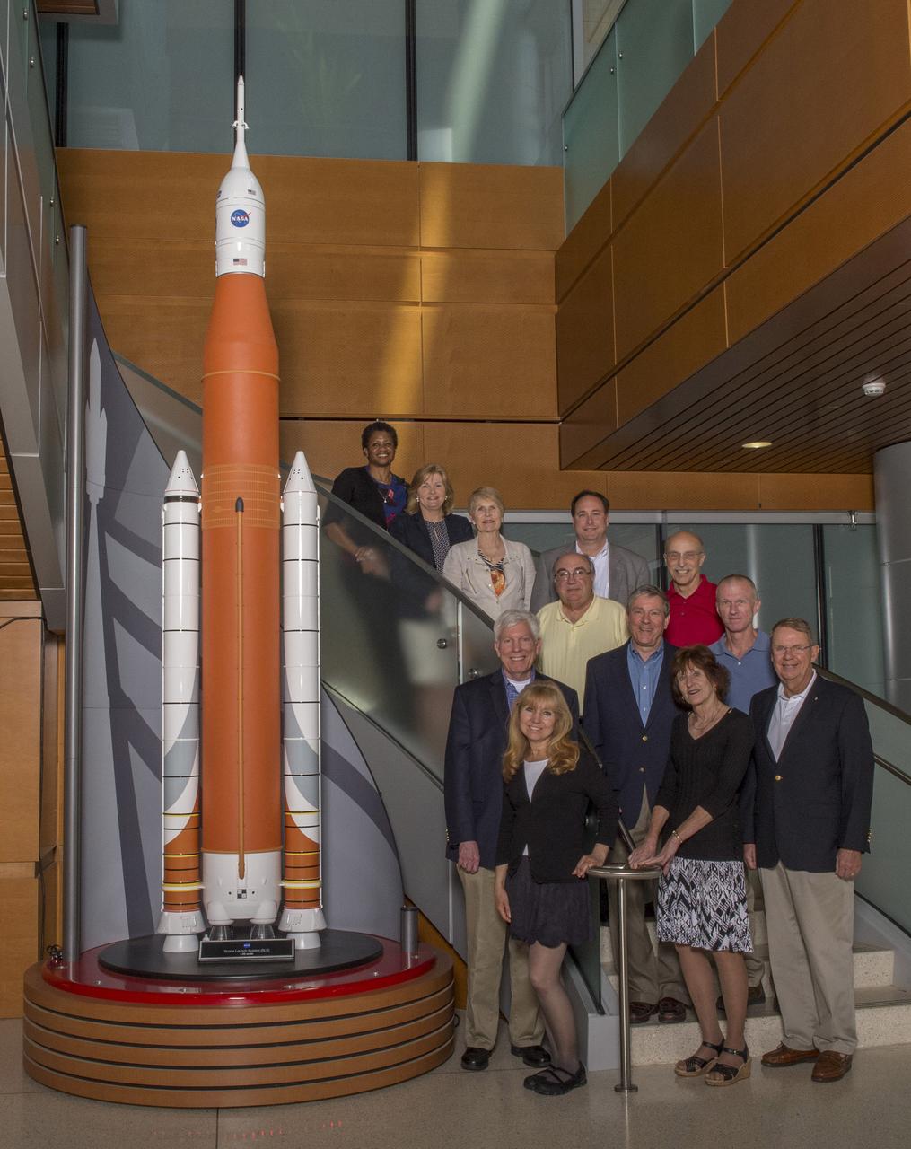
LESA ROE, SECOND FROM TOP, AND ROBERT LIGHTFOOT, FOURTH FROM TOP, POSE WITH MEMBERS OF THE AEROSPACE SAFETY ADVISORY PANEL, (ASAP), IN BLDG 4220 LOBBY
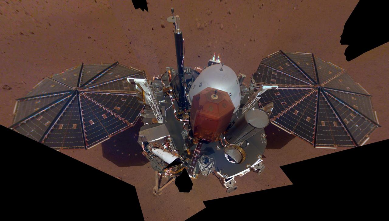
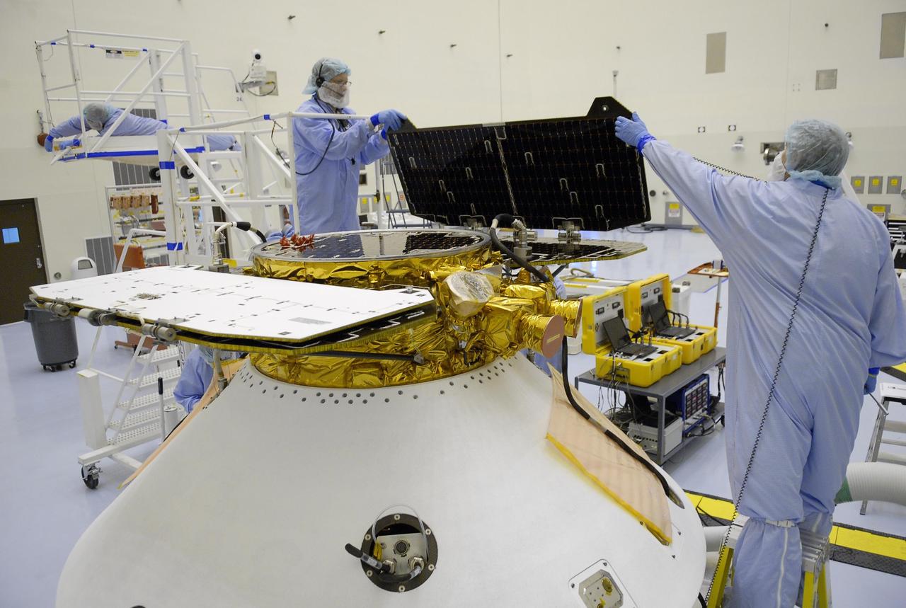
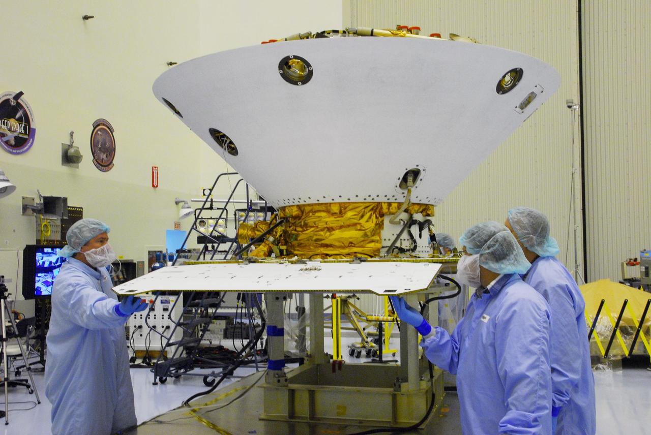
This is NASA InSight's first full selfie on Mars. It displays the lander's solar panels and deck. On top of the deck are its science instruments, weather sensor booms and UHF antenna. The selfie was taken on Dec. 6, 2018 (Sol 10). The selfie is made up of 11 images which were taken by its Instrument Deployment Camera, located on the elbow of its robotic arm. Those images are then stitched together into a mosaic. https://photojournal.jpl.nasa.gov/catalog/PIA22876
The ESA (European Space Agency) Euclid telescope, with contributions from NASA, is shown here on Friday 23 June, being secured to the adaptor of a SpaceX Falcon 9 rocket before launch. Black solar panels line the right side of the spacecraft. The telescope will view the cosmos through the top of the white cylinder that sits above the spacecraft's instruments. https://photojournal.jpl.nasa.gov/catalog/PIA25783
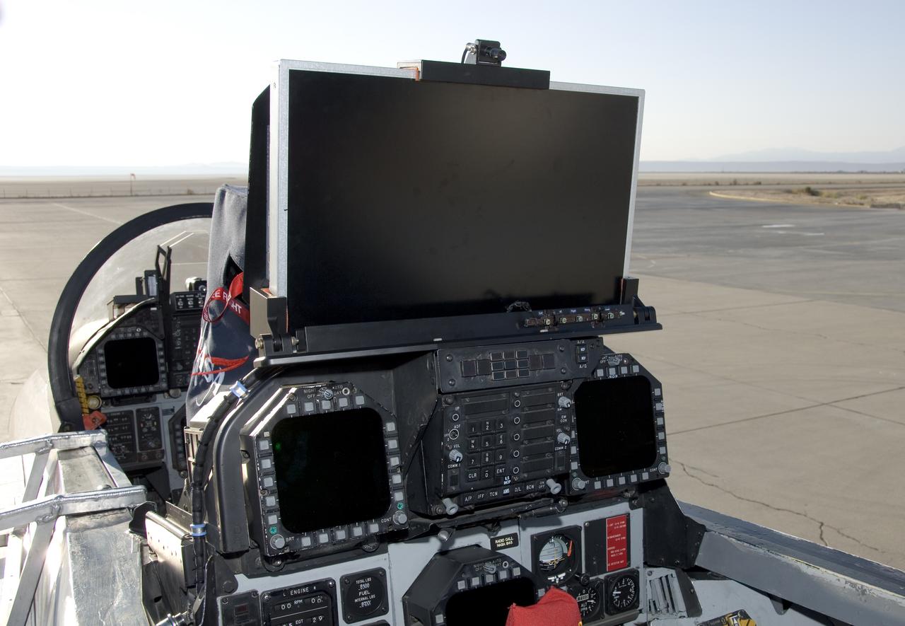
An HD display is mounted on top of the rear instrument panel in NASA's F-18 SRA aircraft, as NASA is partnering with Gulfstream on the External Vision System project.

STS061-95-031 (6 Dec 1993) --- The damaged solar array panel removed from the Hubble Space Telescope (HST) is backdropped over northern Sudan. Astronaut Kathryn C. Thornton, just out of frame at top right, watched the panel after releasing it moments earlier.
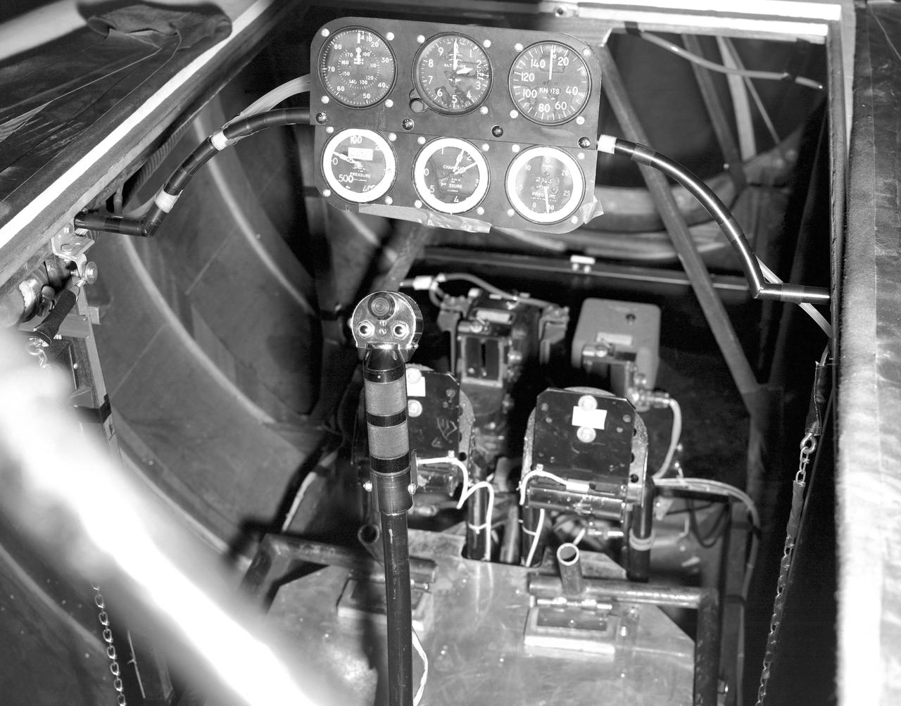
This photo shows the cockpit configuration of the M2-F1 wingless lifting body. With a top speed of about 120 knots, the M2-F1 had a simple instrument panel. Besides the panel itself, the ribs of the wooden shell (left) and the control stick (center) are also visible.
jsc2021e044611 (8/17/2021) --- A preflight image showing the completed GASPACS CubeSat. Two of the solar panels are visible, along with the endplate of the inflatable boom payload at the top of the CubeSat. Image courtesy of Jack Danos.
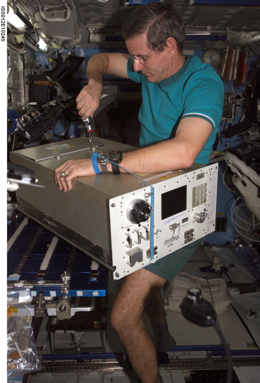
ISS012-E-10245 (5 December 2005) --- Astronaut William S. (Bill) McArthur Jr., Expedition 12 commander and NASA space station science officer, performs in-flight maintenance (IFM) on the Volatile Organic Analyzer (VOA) in the Destiny laboratory of the International Space Station.
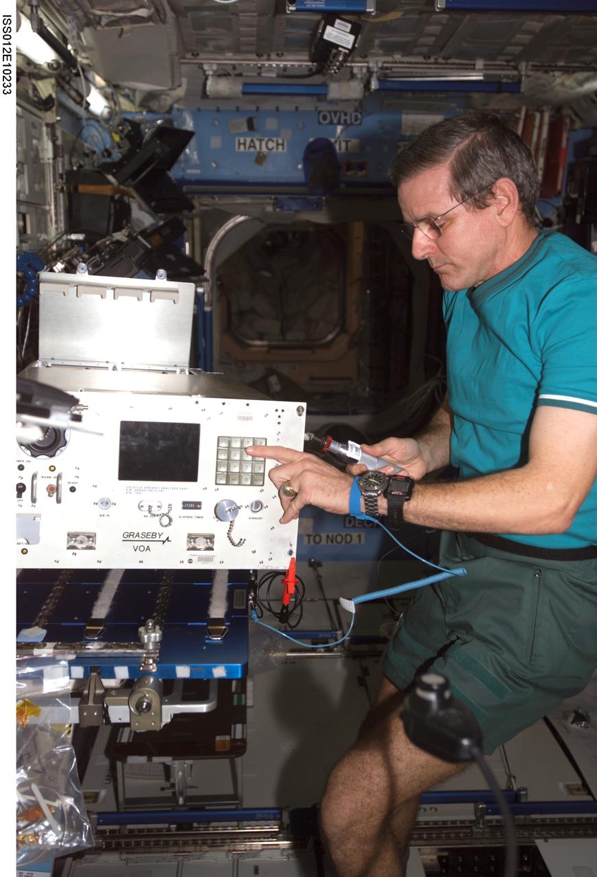
ISS012-E-10233 (5 December 2005) --- Astronaut William S. (Bill) McArthur Jr., Expedition 12 commander and NASA space station science officer, performs in-flight maintenance (IFM) on the Volatile Organic Analyzer (VOA) in the Destiny laboratory of the International Space Station.
KENNEDY SPACE CENTER, FLA. - Old and new carrier panels sit side by side in the Orbiter Processing Facility. The new one in the foreground shows the added thermal barrier that performs as a flow restrictor to further protect the wing leading edges. The panels fit between the Reinforced Carbon Carbon panels and the vehicle on both the top and bottom. They are being installed on the orbiter Discovery. The change is one of the safety features for return to flight. Discovery is the orbiter designated for the Return to Flight mission, STS-114. The launch window is May 12 to June 3, 2005.

ISS041-E-009477 (13 Sept. 2014) --- One of the Expedition 41 crew members aboard the Earth-orbiting International Space Station on Sept. 13, 2014 captured this image of a starry sky. The white panel at left belonging to the ATV-5 spacecraft, which is docked with the orbital outpost, obstructs the view of Scorpius. The red star Antares is directly to the left of the bottom of the second ATV panel from the top. The two stars that are close together and on the lower left of the photo comprise Shaula, the tip of the scorpion?s tail. The open cluster close to Shaula is M7. A solar panel belonging to Russia's service module or Zvezdza runs along the right side of the bottom of the frame.
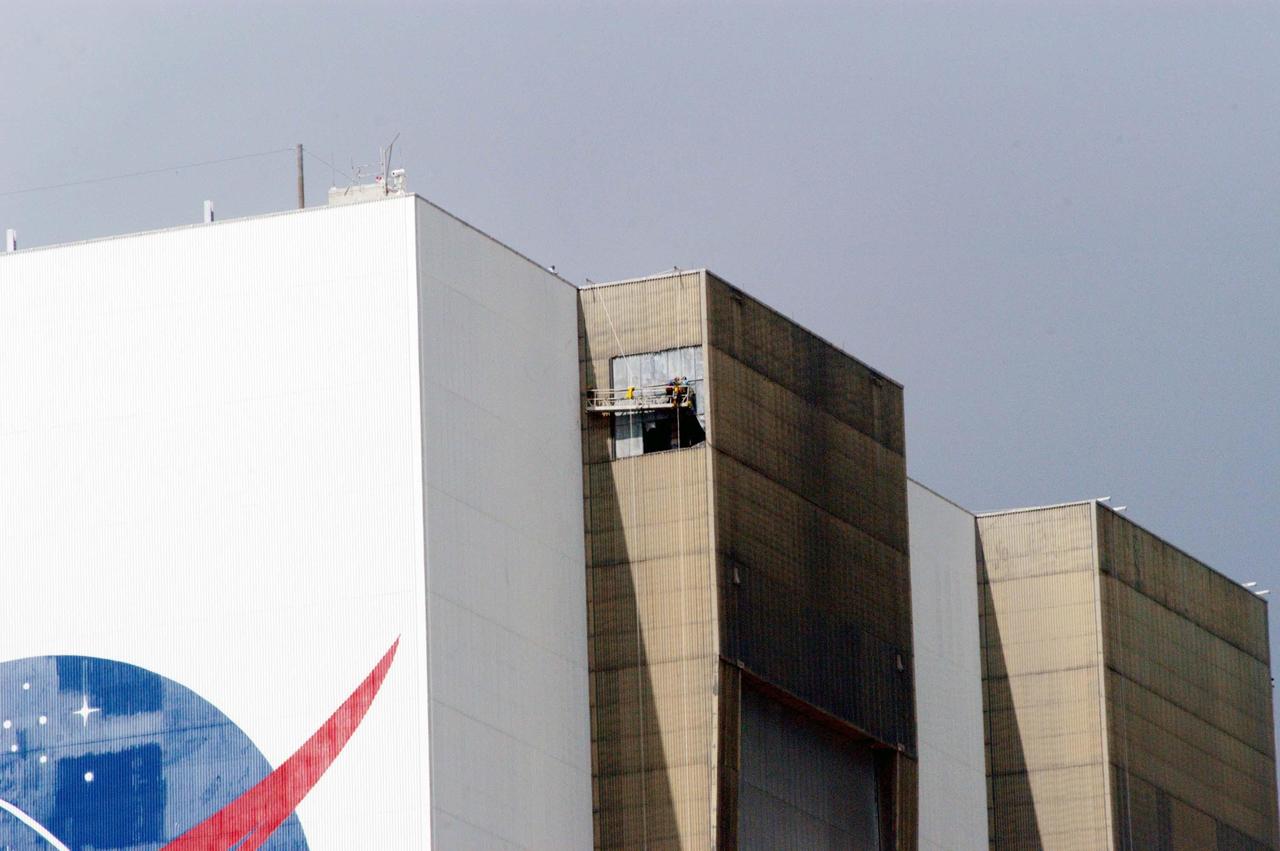
KENNEDY SPACE CENTER, FLA. - On a scaffold suspended near the top of the east side of the Vehicle Assembly Building, workers are covering the holes with corrugated steel so the facility can be returned to performing operational activities. The VAB lost 820 panels from the south wall during Hurricane Frances, and 25 additional panels during Hurricane Jeanne. The VAB stands 525 feet tall. Central Florida, including Kennedy Space Center, was battered by four hurricanes between Aug. 13 and Sept. 26.
STS106-388-011 (8-20 September 2000) --- Cosmonaut Yuri I. Malenchenko (top), and astronaut Edward T. Lu, both mission specialists, work inside panels in the Zvezda Service Module on the International Space Station (ISS). Malenchenko represents Rosaviakosmos.
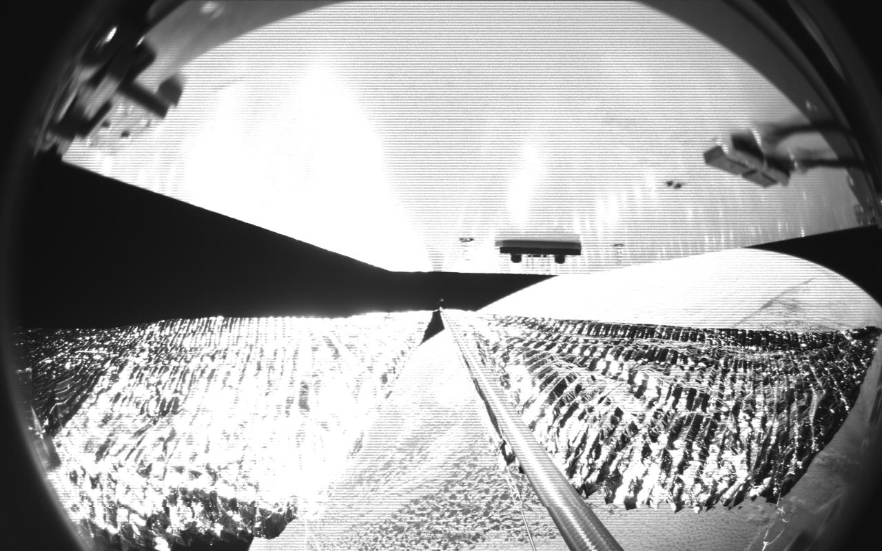
Four cameras aboard the Advanced Composite Solar Sail System spacecraft show the four reflective sail quadrants supported by composite booms. The booms are mounted at right angles and the spacecraft’s solar panel is rectangular, but lines appear distorted because of the wide-angle camera field of view. View from a black-and-white wide-angle camera aboard the Advanced Composite Solar Sail System taken during sail unfurling in low Earth orbit. The spacecraft has four such cameras, centrally located aboard the spacecraft. Here, reflective sail quadrants supported by composite booms are seen when the booms are partially extended and the sail quadrants are not taut. At the top of the photo is the back surface of one of the spacecraft’s solar panels. On the lower right Earth is seen below.
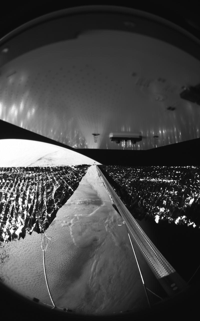
Four cameras aboard the Advanced Composite Solar Sail System spacecraft show the four reflective sail quadrants supported by composite booms. The booms are mounted at right angles and the spacecraft’s solar panel is rectangular, but lines appear distorted because of the wide-angle camera field of view. View from a black-and-white wide-angle camera aboard the Advanced Composite Solar Sail System taken during sail unfurling in low Earth orbit. The spacecraft has four such cameras, centrally located aboard the spacecraft. Here, reflective sail quadrants supported by composite booms are seen when the booms are partially extended and the sail quadrants are not taut. At the top of the photo is the back surface of one of the spacecraft’s solar panels. On the lower left Earth is seen below.
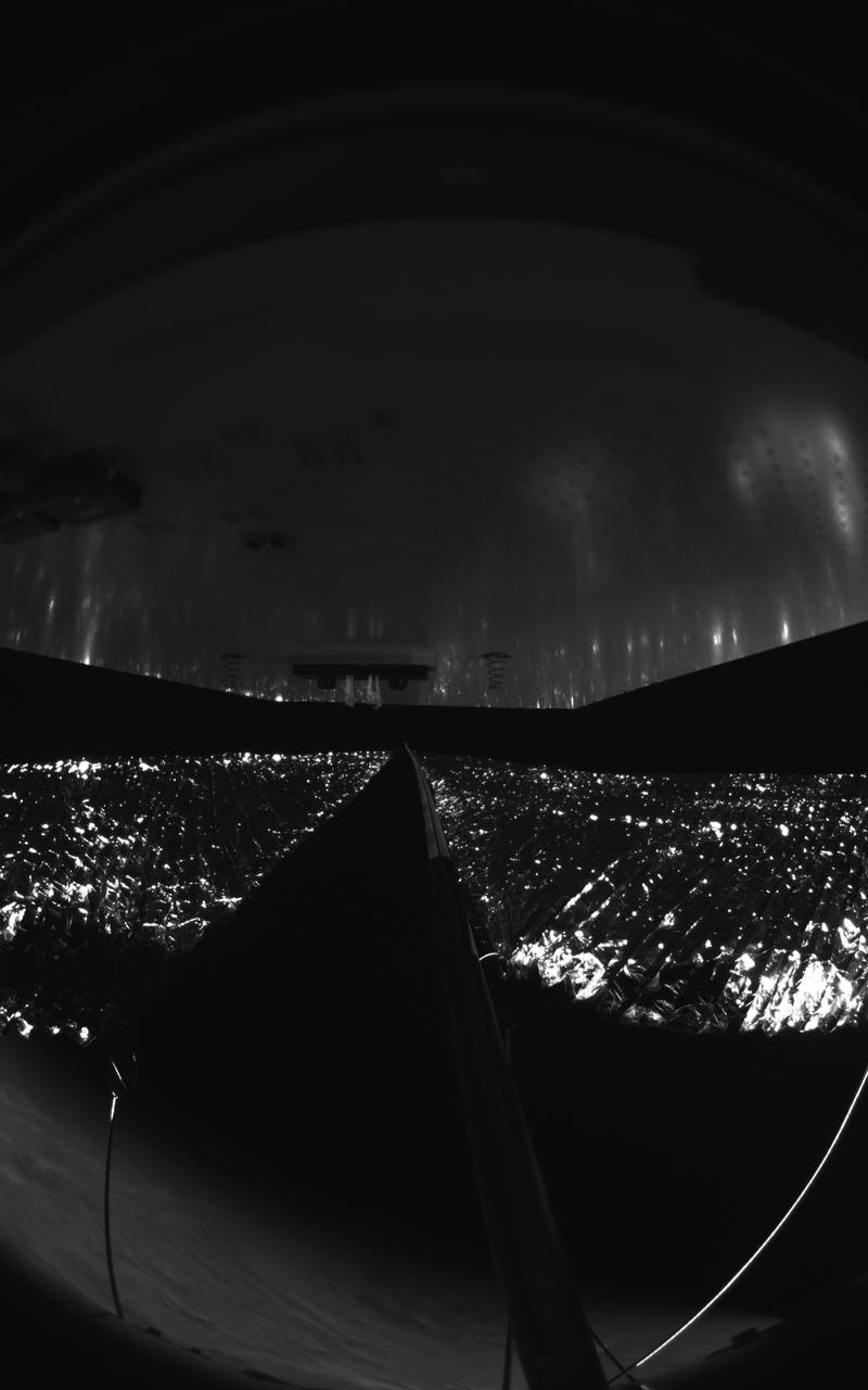
Four cameras aboard the Advanced Composite Solar Sail System spacecraft show the four reflective sail quadrants supported by composite booms. The booms are mounted at right angles and the spacecraft’s solar panel is rectangular, but lines appear distorted because of the wide-angle camera field of view. View from a black-and-white wide-angle camera aboard the Advanced Composite Solar Sail System taken during sail unfurling in low Earth orbit. The spacecraft has four such cameras, centrally located aboard the spacecraft. Here, reflective sail quadrants supported by composite booms are seen when the booms are partially extended and the sail quadrants are not taut. At the top of the photo is the back surface of one of the spacecraft’s solar panels. On the lower left Earth’s limb is seen below.
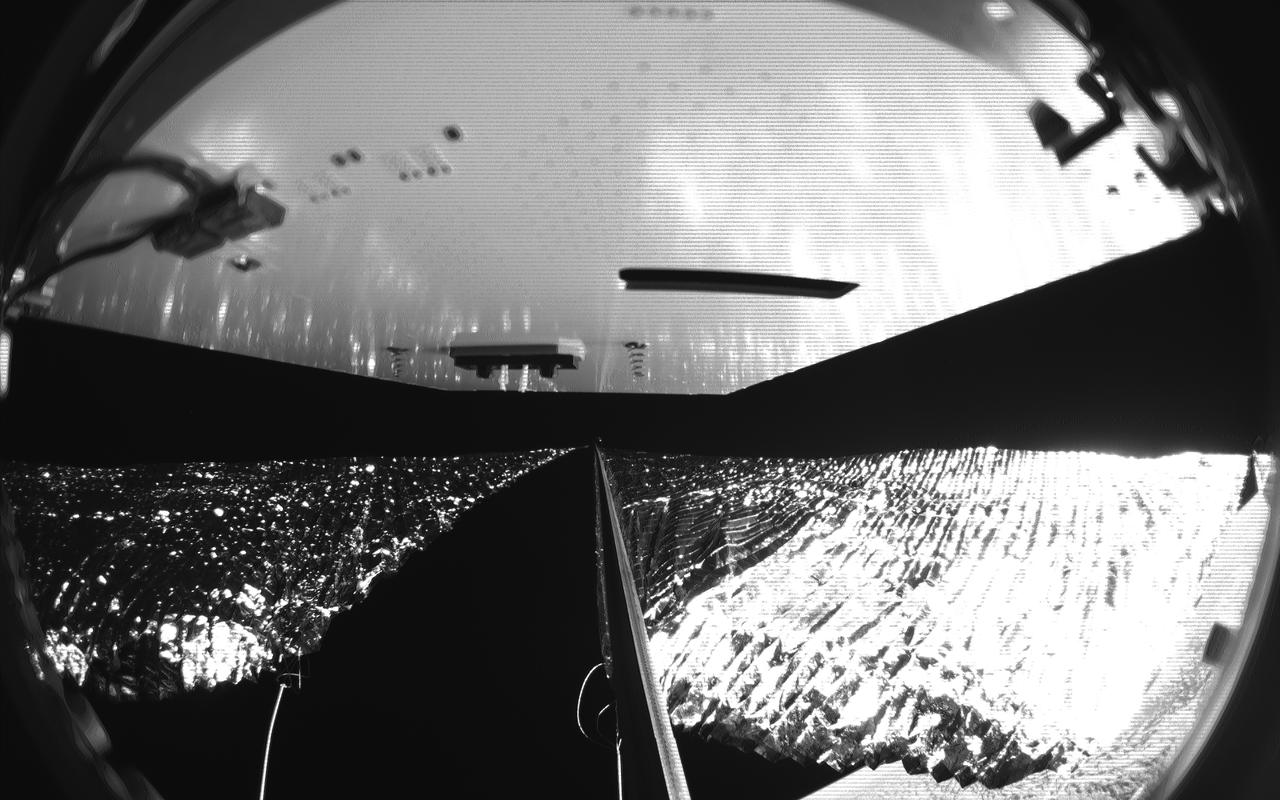
Four cameras aboard the Advanced Composite Solar Sail System spacecraft show the four reflective sail quadrants supported by composite booms. The booms are mounted at right angles and the spacecraft’s solar panel is rectangular, but lines appear distorted because of the wide-angle camera field of view. View from a black-and-white wide-angle camera aboard the Advanced Composite Solar Sail System taken during sail unfurling in low Earth orbit. The spacecraft has four such cameras, centrally located aboard the spacecraft. Here, reflective sail quadrants supported by composite booms are seen when the booms are partially extended and the sail quadrants are not taut. At the top of the photo is the back surface of one of the spacecraft’s solar panels. On the lower right Earth is seen below.
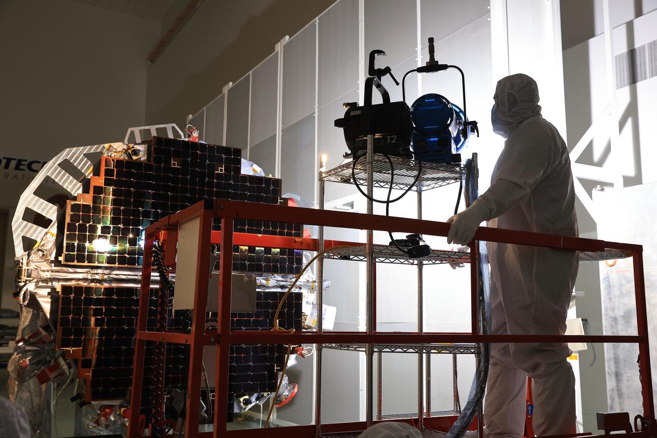
Technicians at the Astrotech Space Operations Facility near NASA’s Kennedy Space Center in Florida install the two-panel solar array on Thursday, July 17, 2025, that will help power the agency’s IMAP (Interstellar Mapping and Acceleration Probe) observatory on its upcoming journey one million miles away from Earth. Each panel of the solar array, located on the top of IMAP, consists of 16 strings of solar cells, with 36 cells per string, and combined will convert sunlight into 500 watts of power, more than enough for the observatory, which as a system uses less power than five 100-watt incandescent light bulbs.
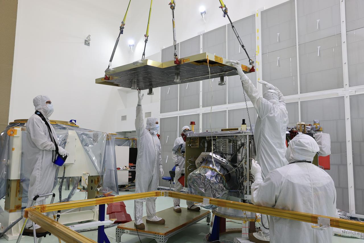
Technicians at the Astrotech Space Operations Facility near NASA’s Kennedy Space Center in Florida install the two-panel solar array on Thursday, July 17, 2025, that will help power the agency’s IMAP (Interstellar Mapping and Acceleration Probe) observatory on its upcoming journey one million miles away from Earth. Each panel of the solar array, located on the top of IMAP, consists of 16 strings of solar cells, with 36 cells per string, and combined will convert sunlight into 500 watts of power, more than enough for the observatory, which as a system uses less power than five 100-watt incandescent light bulbs.
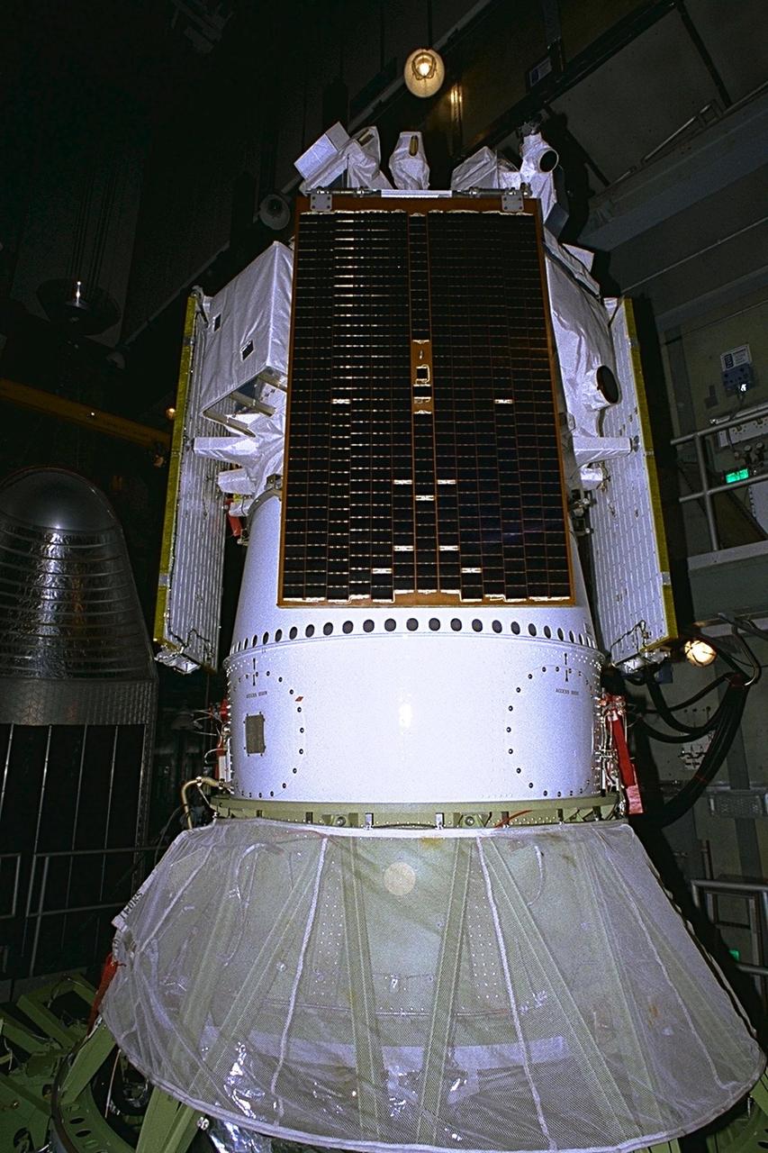
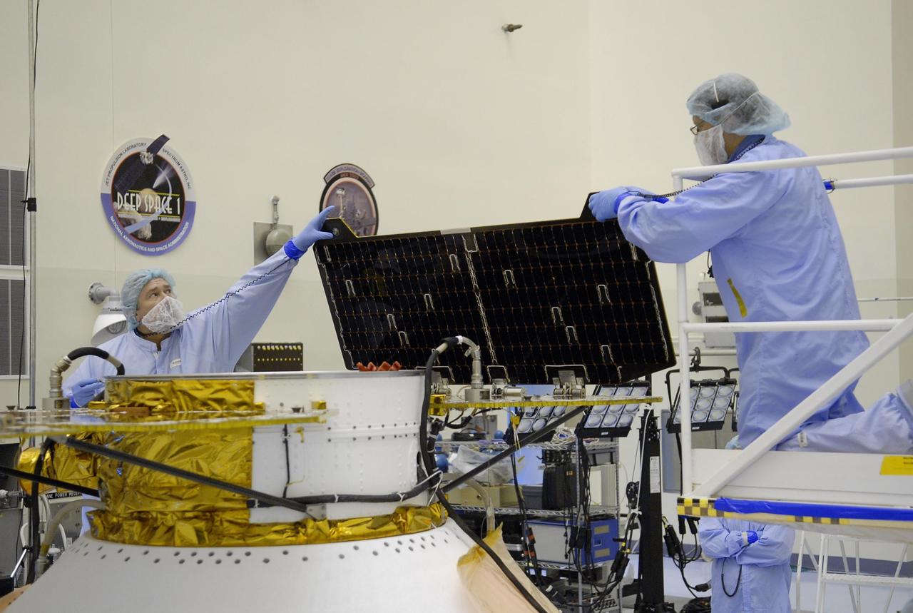
In the Payload Hazardous Servicing Facility, workers remove one of the Stardust solar panels for testing. The spacecraft Stardust will be launched aboard a Boeing Delta 7426 rocket from Complex 17, Cape Canaveral Air Station, targeted for Feb. 6, 1999. Stardust will use a unique medium called aerogel to capture comet particles flying off the nucleus of comet Wild 2 in January 2004, plus collect interstellar dust for later analysis. The collected samples will return to Earth in a re-entry capsule (seen on top, next to the solar panel) to be jettisoned from Stardust as it swings by Earth in January 2006
Technicians at the Astrotech Space Operations Facility near NASA’s Kennedy Space Center in Florida install the two-panel solar array on Thursday, July 17, 2025, that will help power the agency’s IMAP (Interstellar Mapping and Acceleration Probe) observatory on its upcoming journey one million miles away from Earth. Each panel of the solar array, located on the top of IMAP, consists of 16 strings of solar cells, with 36 cells per string, and combined will convert sunlight into 500 watts of power, more than enough for the observatory, which as a system uses less power than five 100-watt incandescent light bulbs.
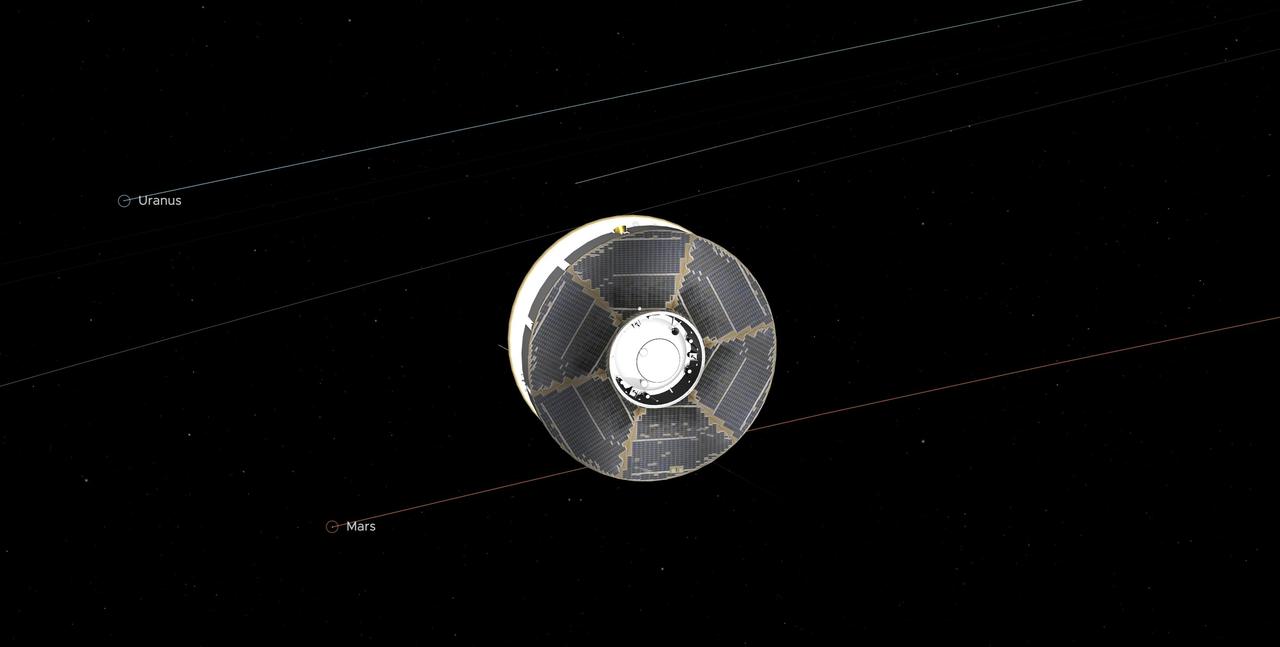
This illustration of the Mars 2020 spacecraft (the solar-panel-covered cruise stage most visible here along with a portion of the white back shell) in interplanetary space was generated using imagery from NASA's Eyes on the Solar System. The image is from the mission's midway point between Earth and Mars — 146.3 million miles (235.4 million kilometers) away from each. In straight-line distance, Earth is 26.6 million miles (42.7 million kilometers) behind Perseverance, and Mars is 17.9 million miles (28.8 million kilometers) in front. Visible in the graphic are the solar panels on the cruise stage surrounding the top of the aeroshell. https://photojournal.jpl.nasa.gov/catalog/PIA24231
Technicians at the Astrotech Space Operations Facility near NASA’s Kennedy Space Center in Florida install the two-panel solar array on Thursday, July 17, 2025, that will help power the agency’s IMAP (Interstellar Mapping and Acceleration Probe) observatory on its upcoming journey one million miles away from Earth. Each panel of the solar array, located on the top of IMAP, consists of 16 strings of solar cells, with 36 cells per string, and combined will convert sunlight into 500 watts of power, more than enough for the observatory, which as a system uses less power than five 100-watt incandescent light bulbs.
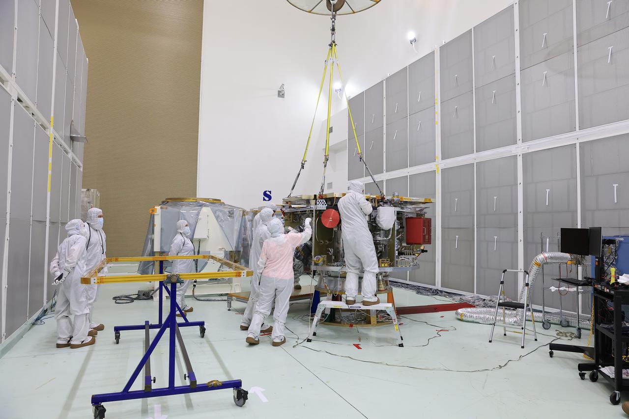
Technicians at the Astrotech Space Operations Facility near NASA’s Kennedy Space Center in Florida install the two-panel solar array on Thursday, July 17, 2025, that will help power the agency’s IMAP (Interstellar Mapping and Acceleration Probe) observatory on its upcoming journey one million miles away from Earth. Each panel of the solar array, located on the top of IMAP, consists of 16 strings of solar cells, with 36 cells per string, and combined will convert sunlight into 500 watts of power, more than enough for the observatory, which as a system uses less power than five 100-watt incandescent light bulbs.
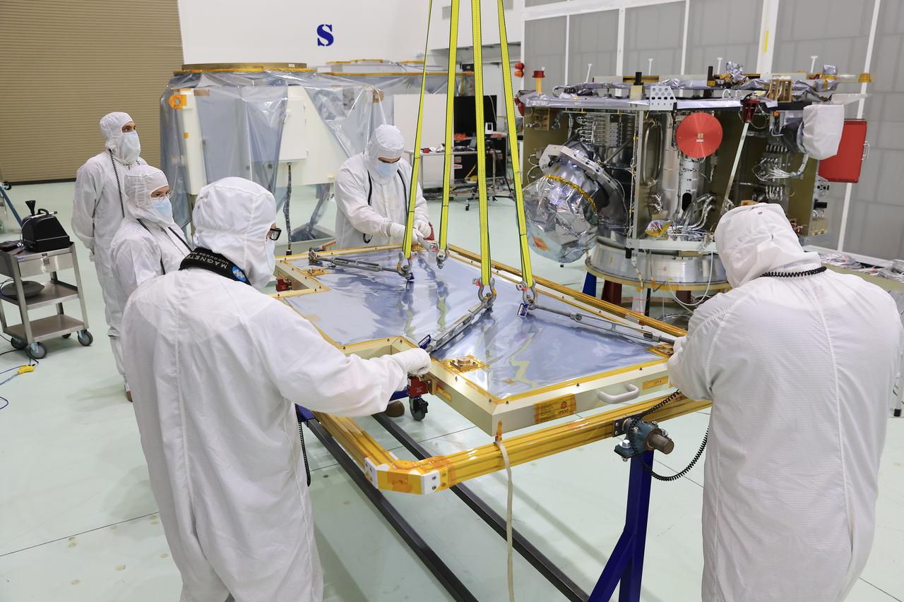
Technicians at the Astrotech Space Operations Facility near NASA’s Kennedy Space Center in Florida install the two-panel solar array on Thursday, July 17, 2025, that will help power the agency’s IMAP (Interstellar Mapping and Acceleration Probe) observatory on its upcoming journey one million miles away from Earth. Each panel of the solar array, located on the top of IMAP, consists of 16 strings of solar cells, with 36 cells per string, and combined will convert sunlight into 500 watts of power, more than enough for the observatory, which as a system uses less power than five 100-watt incandescent light bulbs.
Technicians at the Astrotech Space Operations Facility near NASA’s Kennedy Space Center in Florida install the two-panel solar array on Thursday, July 17, 2025, that will help power the agency’s IMAP (Interstellar Mapping and Acceleration Probe) observatory on its upcoming journey one million miles away from Earth. Each panel of the solar array, located on the top of IMAP, consists of 16 strings of solar cells, with 36 cells per string, and combined will convert sunlight into 500 watts of power, more than enough for the observatory, which as a system uses less power than five 100-watt incandescent light bulbs.
Technicians at the Astrotech Space Operations Facility near NASA’s Kennedy Space Center in Florida install the two-panel solar array on Thursday, July 17, 2025, that will help power the agency’s IMAP (Interstellar Mapping and Acceleration Probe) observatory on its upcoming journey one million miles away from Earth. Each panel of the solar array, located on the top of IMAP, consists of 16 strings of solar cells, with 36 cells per string, and combined will convert sunlight into 500 watts of power, more than enough for the observatory, which as a system uses less power than five 100-watt incandescent light bulbs.
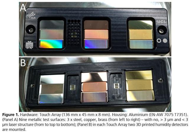
jsc2021e037879 (8/24/2021) --- A preflight view of the Touching Surfaces investigation hardware. The Touch Array (136 mm x 45 mm x 8 mm). Housing : Aluminum (EN-AW 7075 T7351). (Panel A) Nine metallic test surfaces: 3 x steel, copper, brass (from left to right) – with no greater than 3 ?m and less than 3 ?m laser structure (from top to bottom); (Panel B) in each Touch Array two 3 printed humidity detectors are mounted. Image Courtesy DLR
Technicians at the Astrotech Space Operations Facility near NASA’s Kennedy Space Center in Florida install the two-panel solar array on Thursday, July 17, 2025, that will help power the agency’s IMAP (Interstellar Mapping and Acceleration Probe) observatory on its upcoming journey one million miles away from Earth. Each panel of the solar array, located on the top of IMAP, consists of 16 strings of solar cells, with 36 cells per string, and combined will convert sunlight into 500 watts of power, more than enough for the observatory, which as a system uses less power than five 100-watt incandescent light bulbs.
This movie shows three views of the Martian moon Phobos as viewed in visible light by NASA's 2001 Mars Odyssey orbiter. The apparent motion is due to movement by Odyssey's infrared camera, Thermal Emission Imaging System (THEMIS), rather than movement by the moon. Each of the three panels is a series of images taken on different dates (from top to bottom): Sept. 29, 2017; Feb. 15, 2018; and April 24, 2019. Deimos, Mars' other moon, can also be seen in the second panel. While displayed here in visible-wavelength light, THEMIS also recorded thermal-infrared imagery in the same scan. Movie available at https://photojournal.jpl.nasa.gov/catalog/PIA23208
Technicians at the Astrotech Space Operations Facility near NASA’s Kennedy Space Center in Florida install the two-panel solar array on Thursday, July 17, 2025, that will help power the agency’s IMAP (Interstellar Mapping and Acceleration Probe) observatory on its upcoming journey one million miles away from Earth. Each panel of the solar array, located on the top of IMAP, consists of 16 strings of solar cells, with 36 cells per string, and combined will convert sunlight into 500 watts of power, more than enough for the observatory, which as a system uses less power than five 100-watt incandescent light bulbs.
KENNEDY SPACE CENTER, FLA. - On a scaffold barely visible along the south wall of the Vehicle Assembly Building near the NASA logo, workers are covering the holes with corrugated steel so the facility can be returned to performing operational activities. The VAB lost 820 panels from the south wall during the storm, and 25 additional panels pulled off the east wall by Hurricane Jeanne. Another scaffold is suspended near the top of the east wall (right side) for repairs. The VAB stands 525 feet tall. Central Florida, including Kennedy Space Center, has been battered by four hurricanes between Aug. 13 and Sept. 26.
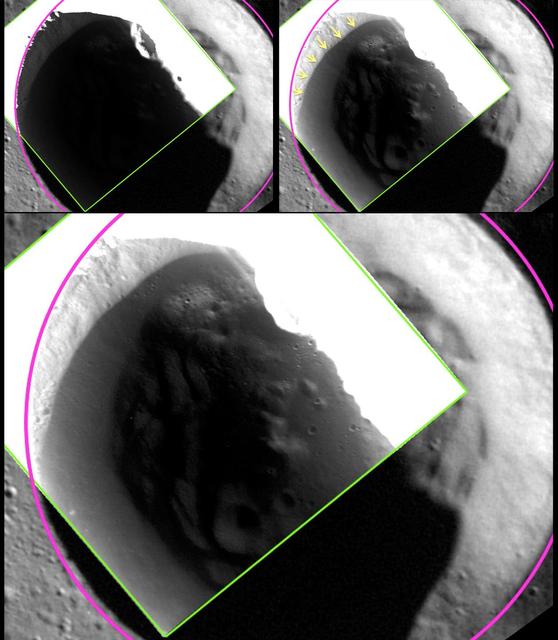
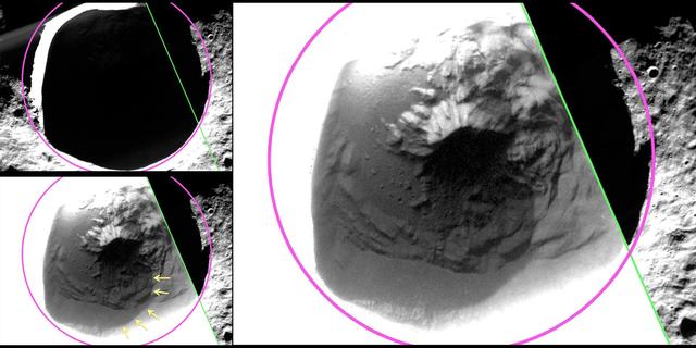
The image shown here was acquired at 24 m/pixel, the highest resolution that has been obtained for any of Mercury's shadowed polar craters. The top left panel shows a view of an unnamed crater in Mercury's north polar region, with the crater rim outlined in pink and the edge of the 24-meter/pixel, low-altitude broadband MDIS image in green. In the large bottom panel, a different stretch has been applied to the same MDIS broadband image, revealing details of the shadowed surface inside the crater. In particular, as highlighted with yellow arrows in the top right panel, the image reveals a region inside the crater that has a lower reflectance. The edge of the low-reflectance region has a sharp and well-defined boundary, even as imaged at this highest resolution of 24 m/pixel. The sharp boundary suggests that the low-reflectance material is sufficiently young to have preserved a sharp boundary against lateral mixing by impact craters. The sharp boundary matches the location predicted by temperature models for the stability of a surficial layer of volatile, organic-rich material tens of centimeters thick that overlies a thicker layer of water ice. http://photojournal.jpl.nasa.gov/catalog/PIA19253
Rebecca Baturin, center, a project engineer in Exploration Ground Systems, speaks to students from Brevard County high schools during a panel discussion session at the NASA Kennedy Space Center Visitor Complex in Florida, on Nov. 7, 2018. The high school seniors were invited to Kennedy Space Center for a tour of facilities, lunch and a roundtable discussion with engineers, scientists and business experts at the center. The 2018 Brevard Top Scholars event was hosted by the center's Academic Engagement Office to honor the top three scholars of the 2018-2019 graduating student class from each of Brevard County’s public high schools. The students received a personalized certificate of recognition at the end of the day.
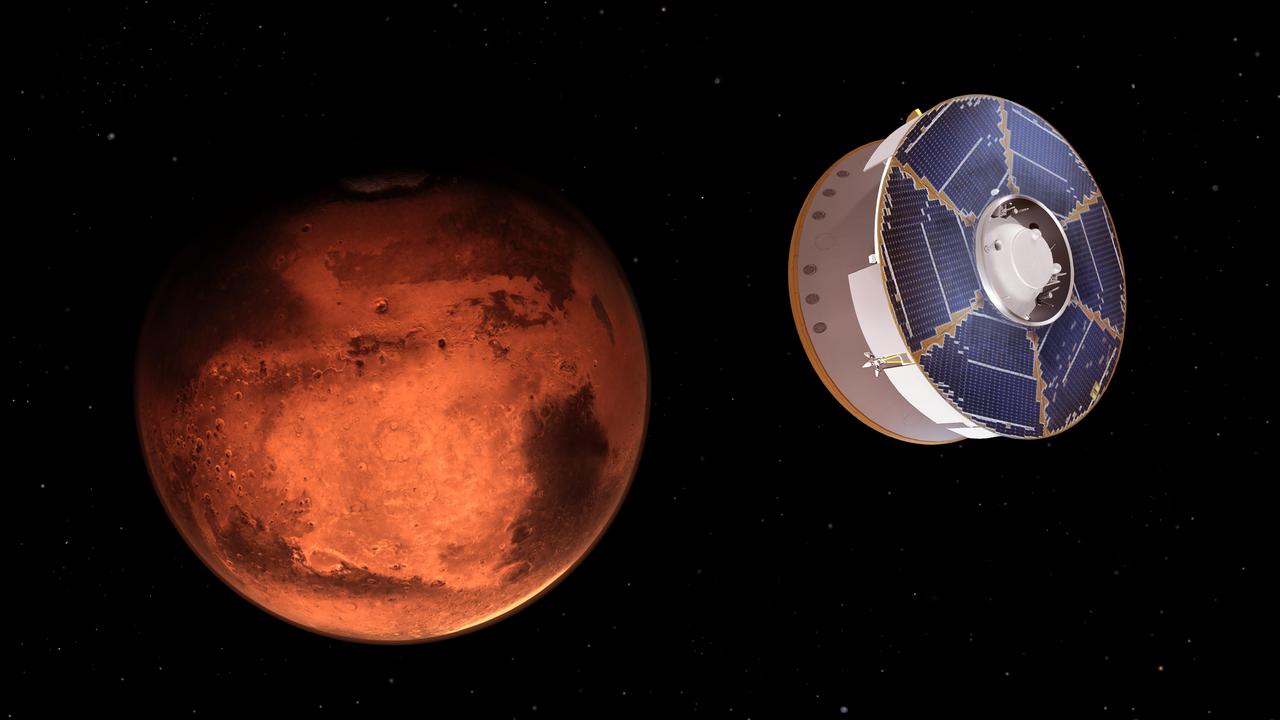
This illustration shows NASA's Mars 2020 spacecraft carrying the Perseverance rover as it approaches Mars. Hundreds of critical events must execute perfectly and exactly on time for the rover to land on Mars safely on Feb. 18, 2021. Solar panels powering the spacecraft are visible on the cruise state at the top. The cruise stage is attached to the aeroshell, which encloses the rover and descent stage. Entry, Descent, and Landing, or "EDL," begins when the aeroshell reaches the top of the Martian atmosphere, traveling nearly 12,500 mph (20,000 kph). It ends about seven minutes later, with Perseverance stationary on the Martian surface. https://photojournal.jpl.nasa.gov/catalog/PIA24311
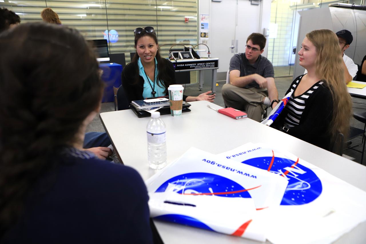
Jo Pereira, center, deputy Human Resources Integration and Pathways Program supervisor, speaks to students from Brevard County high schools during a panel discussion session at the NASA Kennedy Space Center Visitor Complex in Florida, on Nov. 7, 2018. The high school seniors were invited to Kennedy Space Center for a tour of facilities, lunch and a roundtable discussion with engineers, scientists and business experts at the center. The 2018 Brevard Top Scholars event was hosted by the center's Academic Engagement Office to honor the top three scholars of the 2018-2019 graduating student class from each of Brevard County’s public high schools. The students received a personalized certificate of recognition at the end of the day.

jsc2021e052203 (4/12/2021) --- Top view of the completed Binar-1 flight model, waiting for launch. Binar-1 is first Western Australian sovereign spacecraft. The deep blue solar panels seen at the front of the spacecraft will power the two sunken camera lenses seen on the top of the satellite, amongst a plethora of other subsystems. Binar-1 is a 1-Unit (1U) CubeSat, the first in a series from Curtin University in Perth, Australia, to help establish a capability for planetary research. The satellite is developed by a team of students and researchers with the intention to cultivate the skills and technology to build future planetary missions focused on the Moon and small bodies of the solar system. Image courtesy of Curtin University.
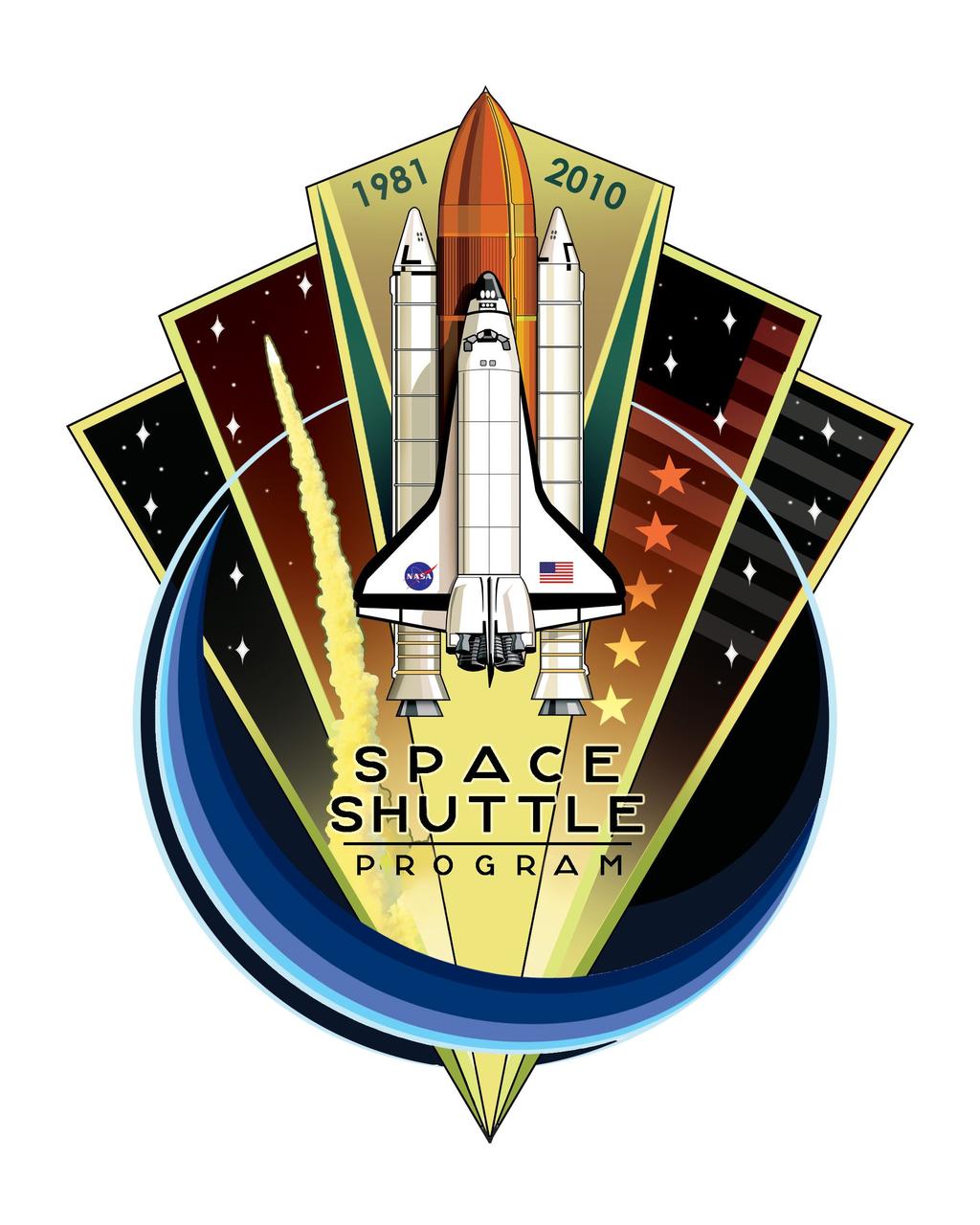
JOHNSON SPACE CENTER, Houston - JSC2010-E-079335 -- To celebrate the upcoming 30th anniversary and retirement of the Space Shuttle Program, the design of this patch aims to capture the visual essence and spirit of the program in an iconic and triumphant manner. As the Space Shuttle Program has been an innovative, iconic gem in the history of American spaceflight, the overall shape of the patch and its faceted panels are reminiscent of a diamond or other fine jewel. The shape of the patch fans out from a fine point at the bottom to a wide array across the top, to evoke the vastness of space and our aim to explore it, as the shuttle has done successfully for decades. The outlined blue circle represents the shuttle's exploration within low Earth orbit, but also creates a dynamic fluidity from the bottom right around to the top left to allude to the smoothness of the shuttle orbiting Earth. The diagonal lines cascading down into the top-right corner of the design form the American Flag as the shuttle has been one of the most recognizable icons in American history throughout the last three decades. In the top left and right panels of the design, there are seven prominent stars on each side, which represent the 14 crew members who were lost on shuttles Challenger and Columbia. Inside of the middle panel to the right of the shuttle, there are five larger, more prominent stars that signify the five space shuttle vehicles NASA has had in its fleet throughout the program. Most importantly though, this patch is as an overall celebration of the much-beloved program and vehicle that so many people have dedicated themselves to in so many capacities throughout the years with a sense of vibrancy and mysticism that the Space Shuttle Program will always be remembered by. This patch was designed by Aerospace Engineer Blake Dumesnil, who has supported the Space Shuttle Program with his work in the Avionics and Energy Systems Divisions of the NASA Johnson Space Center Engineering Directorate. It is the winning entry in a commemorative patch design contest sponsored by the Space Shuttle Program. Image credit: NASA/Blake Dumesnil
Final prelaunch preparations are made at Launch Complex 17A, Cape Canaveral Air Station, for liftoff of the Boeing Delta II expendable launch vehicle with the Advanced Composition Explorer (ACE) spacecraft, at top. The black rectangular-shaped panel in front is one of ACE’s solar arrays. ACE will investigate the origin and evolution of solar phenomenon, the formation of solar corona, solar flares and acceleration of the solar wind. This will be the second Delta launch under the Boeing name and the first from Cape Canaveral. Liftoff is scheduled Aug. 24
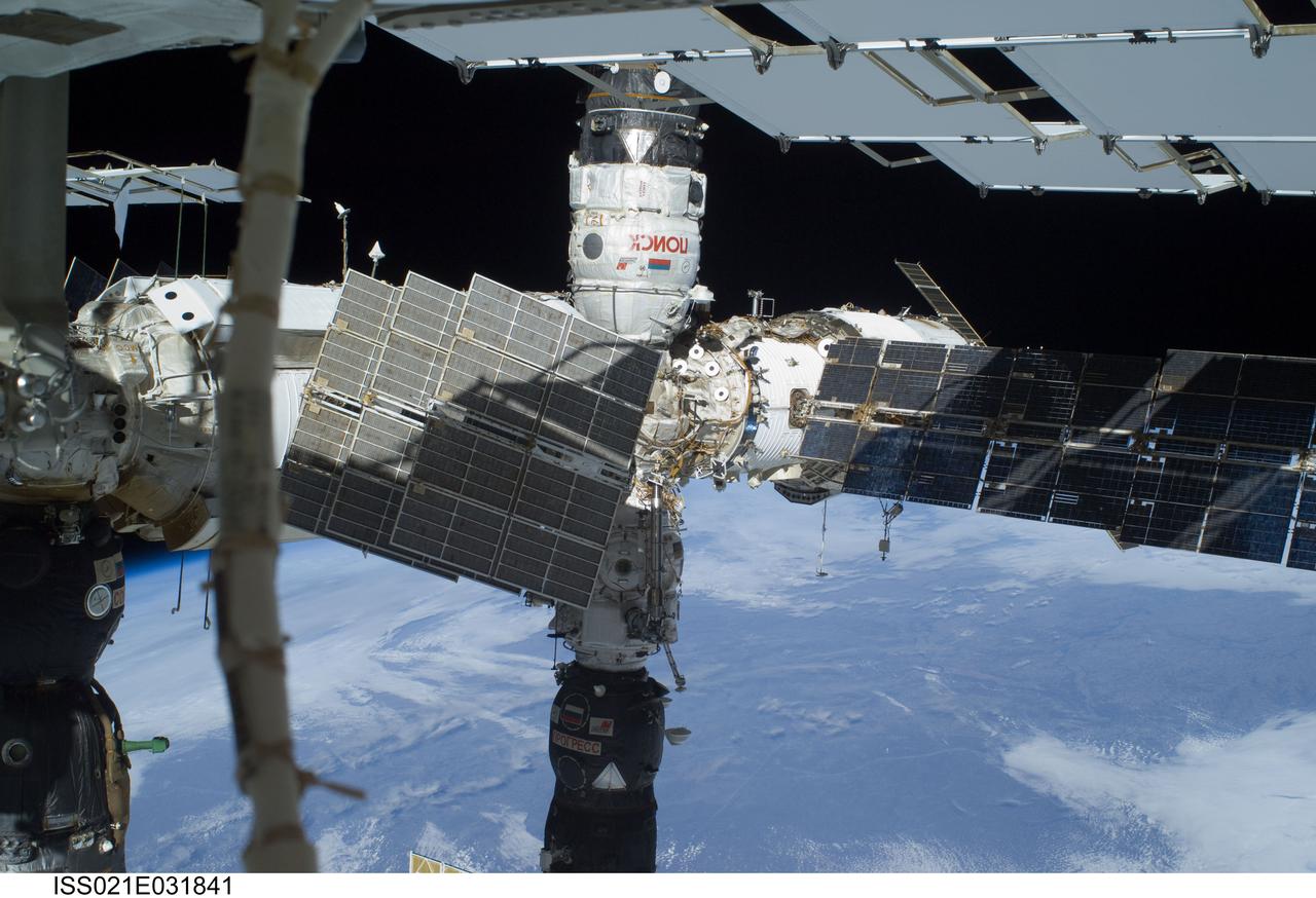
ISS021-E-031841 (23 Nov. 2009) --- The Russian segment of the International Space Station is featured in this image photographed by a space-walking astronaut during the third and final spacewalk for the STS-129 mission. The Poisk Mini Research Module 2 (MRM2), docked to the space-facing port of the Zvezda Service Module, is at top center; and a Progress resupply vehicle is docked to the Pirs Docking Compartment at bottom center. Zarya (partially obscured by solar panels) is at right center. Earth’s horizon and the blackness of space provide the backdrop for the scene.
ISS031-E-41622 (20 May 2012) --- This is one of a series of photos taken by Expedition 31 Flight Engineer Don Pettit aboard the International Space Station, at the time located over the Western Pacific, showing a shadow of the moon created by the May 20 solar eclipse, as the shadow spreads across cloud cover on Earth. Pettit used a 28-mm lens on a digital still camera to record the image at 23:36:45 GMT. One of the space station’s solar array panels appears at the top of the frame.
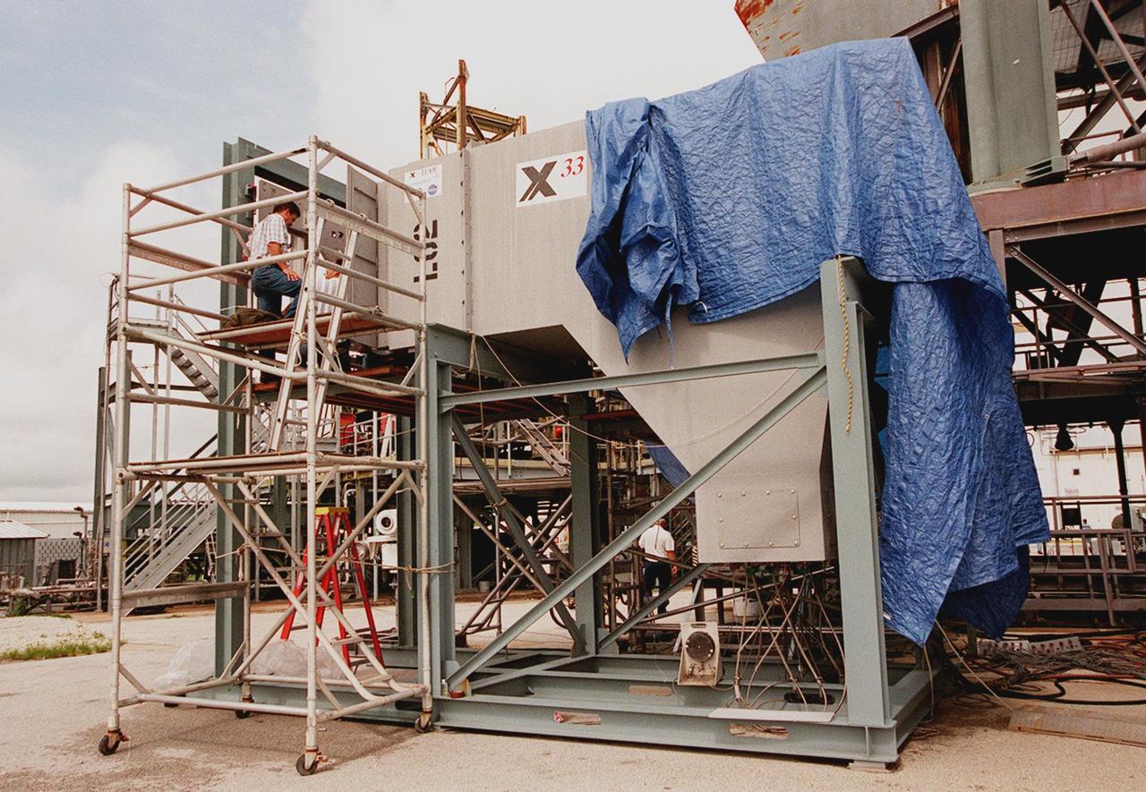
At the Launch Equipment Test Facility, Will Reaves (top of stand), with Lockheed Martin Technical Operations, looks over components of the X-33 umbilical system undergoing testing. A team of Kennedy Space Center experts developed the umbilical system, comprising panels, valves and hoses that provide the means to load the X-33 with super-cold propellant. The X-33, under construction at Lockheed Martin Skunk Works in Palmdale, Calif., is a half-scale prototype of the planned operational reusable launch vehicle dubbed VentureStar
ISS031-E-41595 (20 May 2012) --- This is one of a series of photos taken by Expedition 31 Flight Engineer Don Pettit aboard the International Space Station, at the time located over the Western Pacific, showing a shadow of the moon created by the May 20 solar eclipse, as the shadow spreads across cloud cover on Earth. Pettit used a 28-mm lens on a digital still camera to record the image at 23:35:36 GMT. One of the space station’s solar array panels appears at the top of the frame.
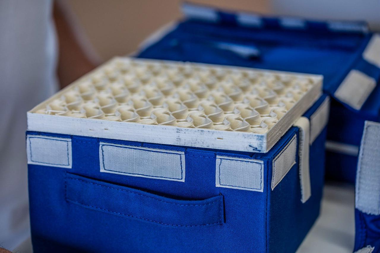
jsc2021e064352 (3/18/2021) --- Preflight imagery of the 3D printed pad with renewable foam used for side/top/bottom panels of the Dreams Kit. The Packaging and Protecting Using Renewable Products (Renewable Foam) project is intended to test foams using products manufactured with renewable resources (or eco-friendly). © CNES/DE PRADA Thierry, 2020
ISS031-E-41594 (20 May 2012) --- This is one of a series of photos taken by Expedition 31 Flight Engineer Don Pettit aboard the International Space Station, showing a shadow of the moon created by the May 20 solar eclipse, as the shadow spreads across cloud cover on Earth. Pettit used a 28-mm lens on a digital still camera to record the image at 23:35:17 GMT. One of the space station’s solar array panels appears at the top of the frame.
JSC2024E043924 (4/14/2025) --- The CosmoGirl-Sat CubeSat from Japan Aerospace Exploration Agency (JAXA) shows deep blue solar panels at the front of the spacecraft that power three sunken camera lenses (seen on the top of the satellite), amongst a plethora of other subsystems. CosmoGirl-Sat is developed by the Cosmo Women’s Amateur Radio Club, and its primary mission is to transmit imagery to a ground station on Earth. Image courtesy of Cosmo Girls Amateur Radio Club.
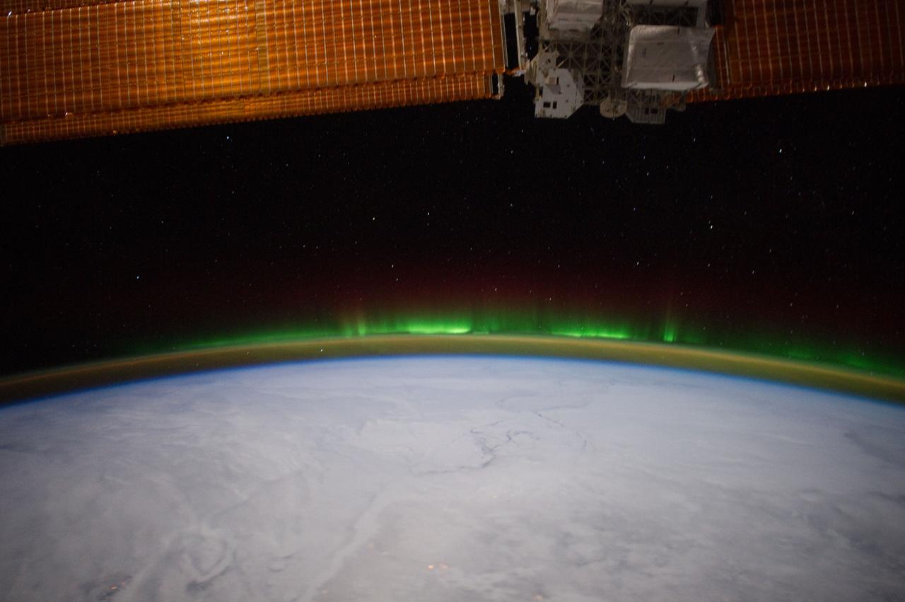
ISS030-E-114095 (6 Feb. 2012)--- Minor activity of Aurora Borealis is easily recognized "piggybacking" Earth's limb in this 24-mm image photographed by one of the Expedition 30 crew members aboard the International Space station from approximately 240 miles above Earth. Clouds obscure what would be any recognizable points on the planet. A section of one of the solar array panels on the orbital outpost is seen across the top of the frame.
MESSENGER's low-altitude campaign has enabled imaging of Fuller crater (named after American architect Buckminster Fuller) in greater detail than previously possible. The top left panel shows an image of Fuller, with the crater rim outlined in pink and the edge of a low-altitude broadband MDIS image in green. The large panel applies a different stretch to the same MDIS broadband image in the first panel, revealing details of the shadowed surface inside Fuller! In particular, as highlighted with yellow arrows in the bottom left panel, the image reveals a region inside Fuller that is lower in reflectance. The edge of the low-reflectance region has a sharp and well-defined boundary, even when imaged at 46 m/pixel, suggesting that the low-reflectance material is sufficiently young to have preserved a sharp boundary against lateral mixing by impact cratering. Models for surface and near-surface temperature within Fuller crater predict a region that is sufficiently cold to host long-lived water ice beneath the surface but too hot to support water ice at the surface. The low-reflectance region revealed in the images matches the thermal characteristics expected for a lag deposit of volatile, organic-rich material that overlies the water ice. http://photojournal.jpl.nasa.gov/catalog/PIA19244
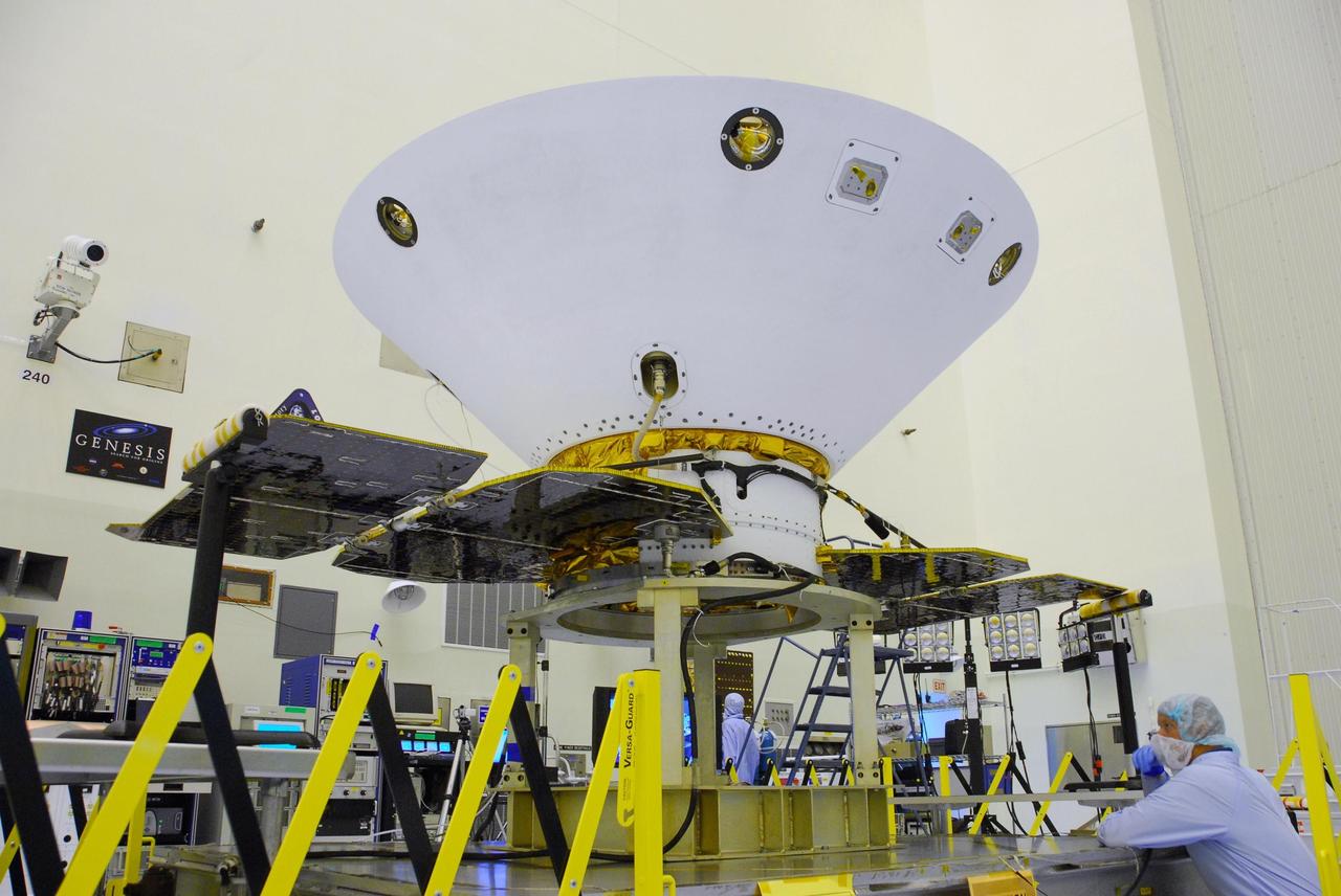
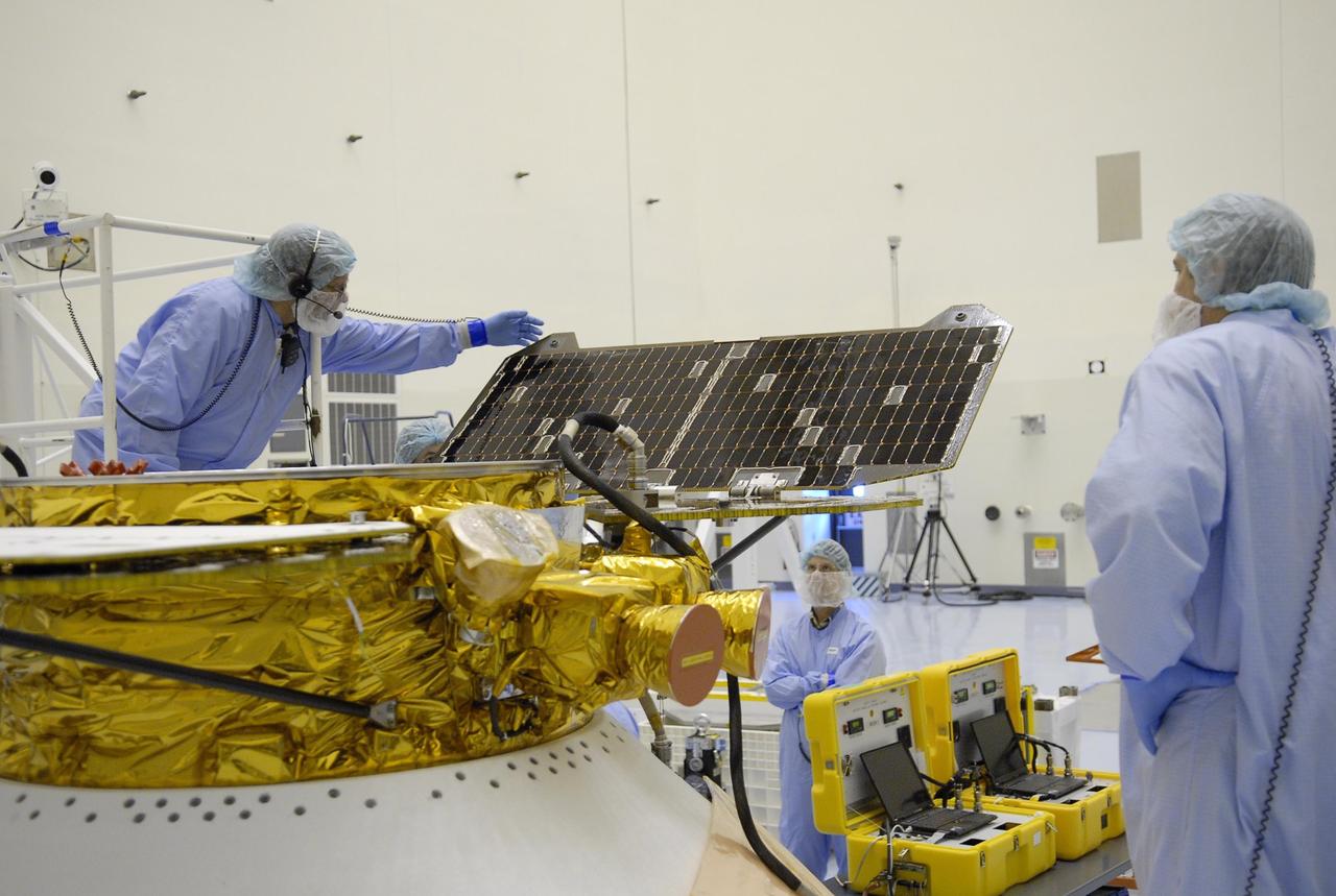
KENNEDY SPACE CENTER, FLA. -- In the Payload Hazardous Servicing Facility at Cape Canaveral Air Force Station, the solar array panels have been unfolded around the Phoenix Mars Lander spacecraft. The deployment of the panels is part of the pre-launch testing under way. Phoenix will land in icy soils near the north polar permanent ice cap of Mars and explore the history of the water in these soils and any associated rocks, while monitoring polar climate. Landing on Mars is planned in May 2008 on arctic ground where a mission currently in orbit, Mars Odyssey, has detected high concentrations of ice just beneath the top layer of soil. Phoenix is scheduled to launch Aug. 3. Photo credit: NASA/George Shelton
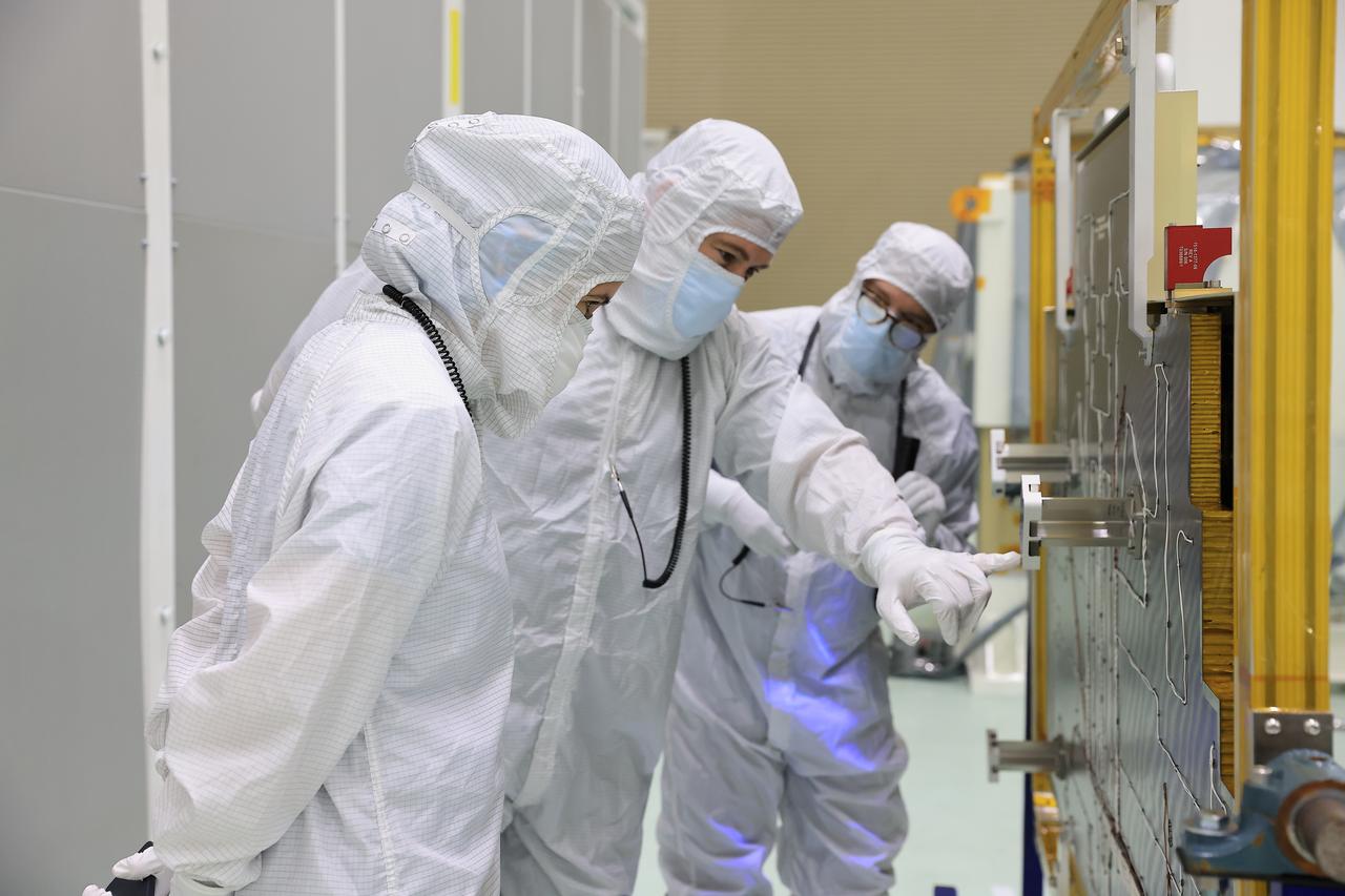
Technicians at the Astrotech Space Operations Facility near NASA’s Kennedy Space Center in Florida conduct illumination testing on Friday, July 18, 2025, by flashing a bright light that simulates the Sun into the two-panel solar array that will help power the agency’s IMAP (Interstellar Mapping and Acceleration Probe) observatory on its upcoming journey to a destination about one million miles away from Earth Lagrange Point 1. Each panel of the solar array, located on the top of IMAP, consists of 16 strings of solar cells, with 36 cells per string, and combined will convert sunlight into 500 watts of power, more than enough for the observatory, which as a system uses less power than five 100-watt incandescent light bulbs.
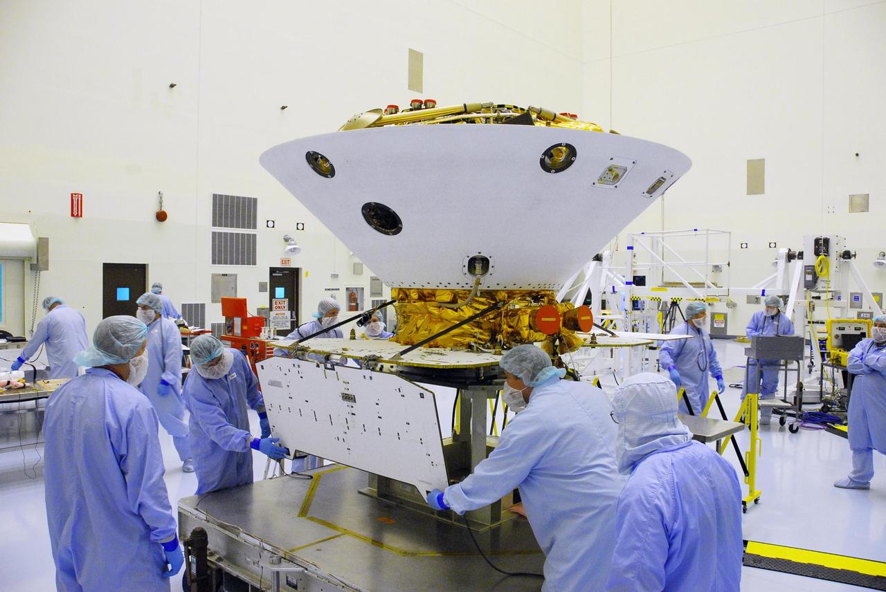
KENNEDY SPACE CENTER, FLA. -- After illumination testing of the solar array panels, technicians begin stowing the panels on the Phoenix Mars Lander spacecraft. The Phoenix will be launched toward Mars to land in icy soils near the planet's north polar permanent ice cap. It will explore the history of the water in these soils and any associated rocks, while monitoring polar climate. Landing on Mars is planned in May 2008 on arctic ground where a mission currently in orbit, Mars Odyssey, has detected high concentrations of ice just beneath the top layer of soil. Phoenix is scheduled to launch Aug. 3 from Pad 17-A at Cape Canaveral Air Force Station . Photo credit: NASA/Kim Shiflett
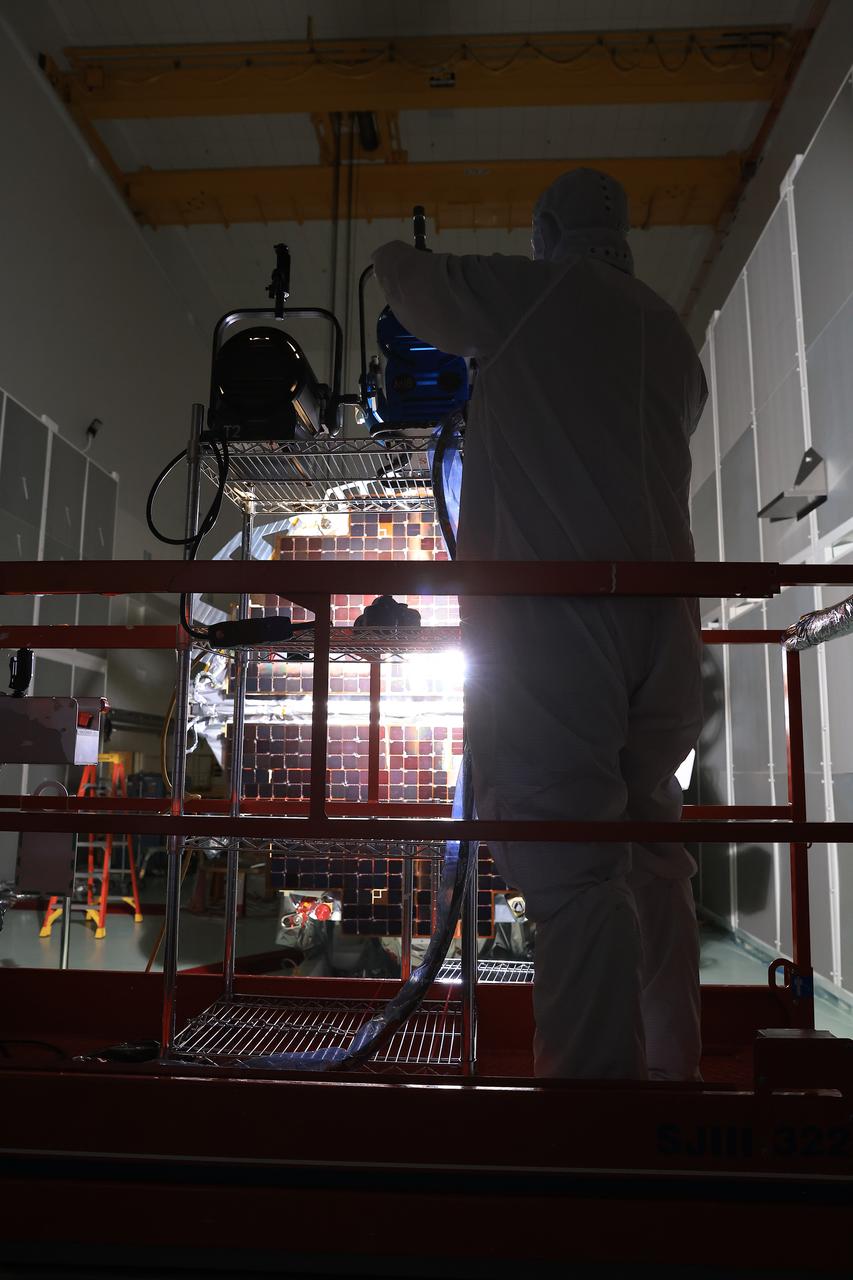
Technicians at the Astrotech Space Operations Facility near NASA’s Kennedy Space Center in Florida conduct illumination testing on Friday, July 18, 2025, by flashing a bright light that simulates the Sun into the two-panel solar array that will help power the agency’s IMAP (Interstellar Mapping and Acceleration Probe) observatory on its upcoming journey to a destination about one million miles away from Earth Lagrange Point 1. Each panel of the solar array, located on the top of IMAP, consists of 16 strings of solar cells, with 36 cells per string, and combined will convert sunlight into 500 watts of power, more than enough for the observatory, which as a system uses less power than five 100-watt incandescent light bulbs.
KENNEDY SPACE CENTER, FLA. -- After illumination testing of the solar array panels, technicians begin stowing the panels on the Phoenix Mars Lander spacecraft. The Phoenix will be launched toward Mars to land in icy soils near the planet's north polar permanent ice cap. It will explore the history of the water in these soils and any associated rocks, while monitoring polar climate. Landing on Mars is planned in May 2008 on arctic ground where a mission currently in orbit, Mars Odyssey, has detected high concentrations of ice just beneath the top layer of soil. Phoenix is scheduled to launch Aug. 3 from Pad 17-A at Cape Canaveral Air Force Station . Photo credit: NASA/Kim Shiflett
Technicians at the Astrotech Space Operations Facility near NASA’s Kennedy Space Center in Florida conduct illumination testing on Friday, July 18, 2025, by flashing a bright light that simulates the Sun into the two-panel solar array that will help power the agency’s IMAP (Interstellar Mapping and Acceleration Probe) observatory on its upcoming journey to a destination about one million miles away from Earth Lagrange Point 1. Each panel of the solar array, located on the top of IMAP, consists of 16 strings of solar cells, with 36 cells per string, and combined will convert sunlight into 500 watts of power, more than enough for the observatory, which as a system uses less power than five 100-watt incandescent light bulbs.
KENNEDY SPACE CENTER, FLA. -- In the Payload Hazardous Servicing Facility at Cape Canaveral Air Force Station, workers prepare the Phoenix Mars Lander spacecraft for solar panel deployment. The deployment of the panels is part of the pre-launch testing under way. Phoenix will land in icy soils near the north polar permanent ice cap of Mars and explore the history of the water in these soils and any associated rocks, while monitoring polar climate. Landing on Mars is planned in May 2008 on arctic ground where a mission currently in orbit, Mars Odyssey, has detected high concentrations of ice just beneath the top layer of soil. Phoenix is scheduled to launch Aug. 3. Photo credit: NASA/George Shelton
KENNEDY SPACE CENTER, FLA. - On the side of NASA Kennedy Space Center’s Vehicle Assembly Building, some panels are missing following the wrath of hurricane Wilma as it crossed the state Oct. 24. Kennedy’s facilities sustained minor structural damage, primarily to roofs or from water intrusion. The Vehicle Assembly Building lost some panels on the east and west sides. Some facilities lost power. A total of 13.6 inches of rain was recorded at the Shuttle Landing Facility. The highest wind gust recorded was 94 mph from the north-northwest at Launch Pad 39B, while the maximum sustained wind was 76 mph from the north-northwest at the top of the 492-foot weather tower located north of the Vehicle Assembly Building.
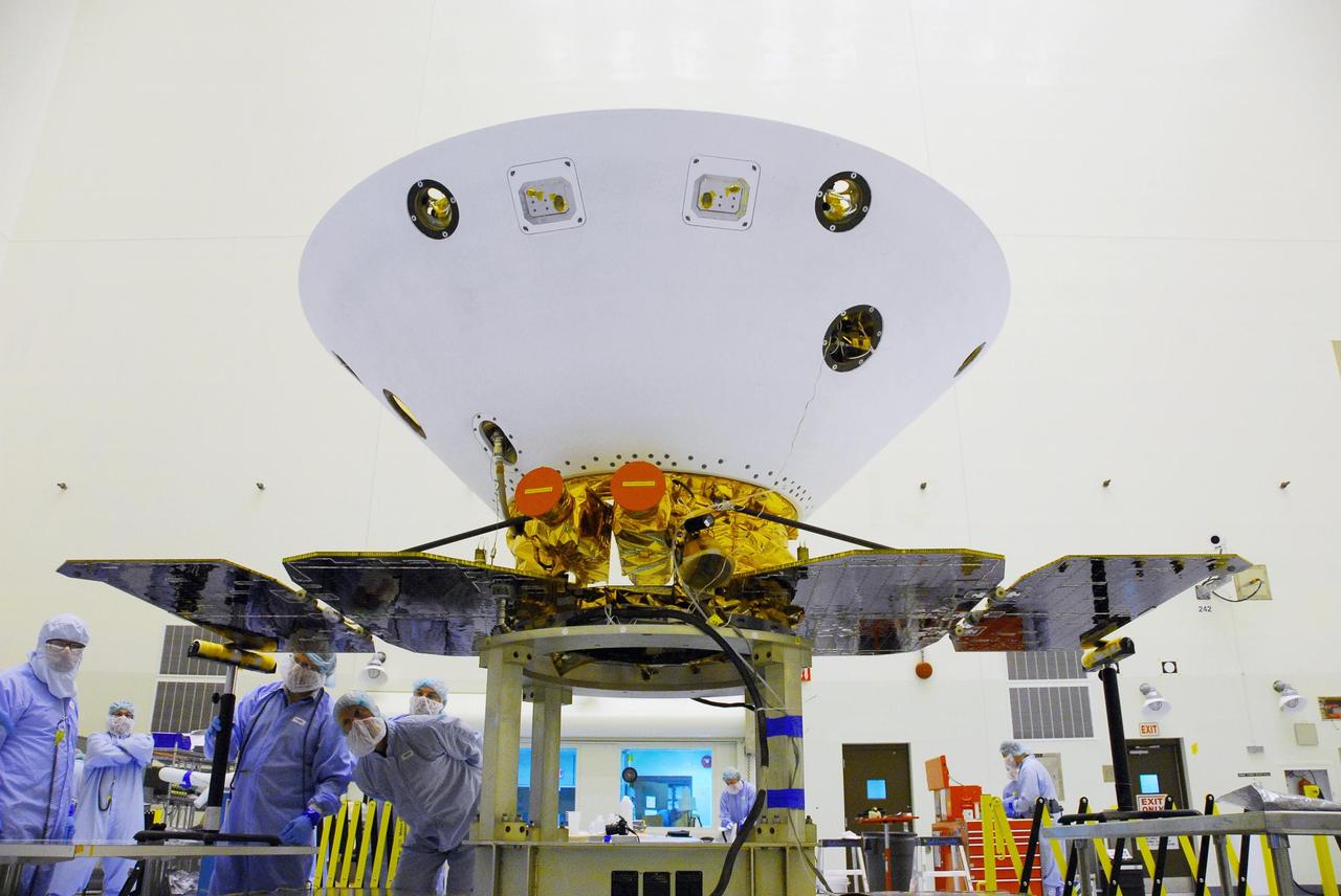
KENNEDY SPACE CENTER, FLA. -- In the Payload Hazardous Servicing Facility at Cape Canaveral Air Force Station, the solar array panels on the Phoenix Mars Lander spacecraft are unfolded. The deployment of the panels is part of the pre-launch testing under way. Phoenix will land in icy soils near the north polar permanent ice cap of Mars and explore the history of the water in these soils and any associated rocks, while monitoring polar climate. Landing on Mars is planned in May 2008 on arctic ground where a mission currently in orbit, Mars Odyssey, has detected high concentrations of ice just beneath the top layer of soil. Phoenix is scheduled to launch Aug. 3. Photo credit: NASA/George Shelton
KENNEDY SPACE CENTER, FLA. -- In the Payload Hazardous Servicing Facility at Cape Canaveral Air Force Station, workers begin unfolding the solar array panels on the Phoenix Mars Lander spacecraft. The deployment of the panels is part of the pre-launch testing under way. Phoenix will land in icy soils near the north polar permanent ice cap of Mars and explore the history of the water in these soils and any associated rocks, while monitoring polar climate. Landing on Mars is planned in May 2008 on arctic ground where a mission currently in orbit, Mars Odyssey, has detected high concentrations of ice just beneath the top layer of soil. Phoenix is scheduled to launch Aug. 3. Photo credit: NASA/George Shelton
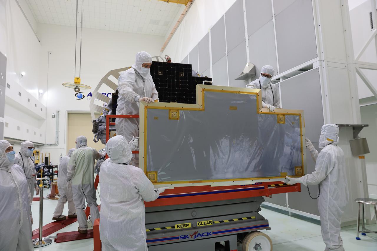
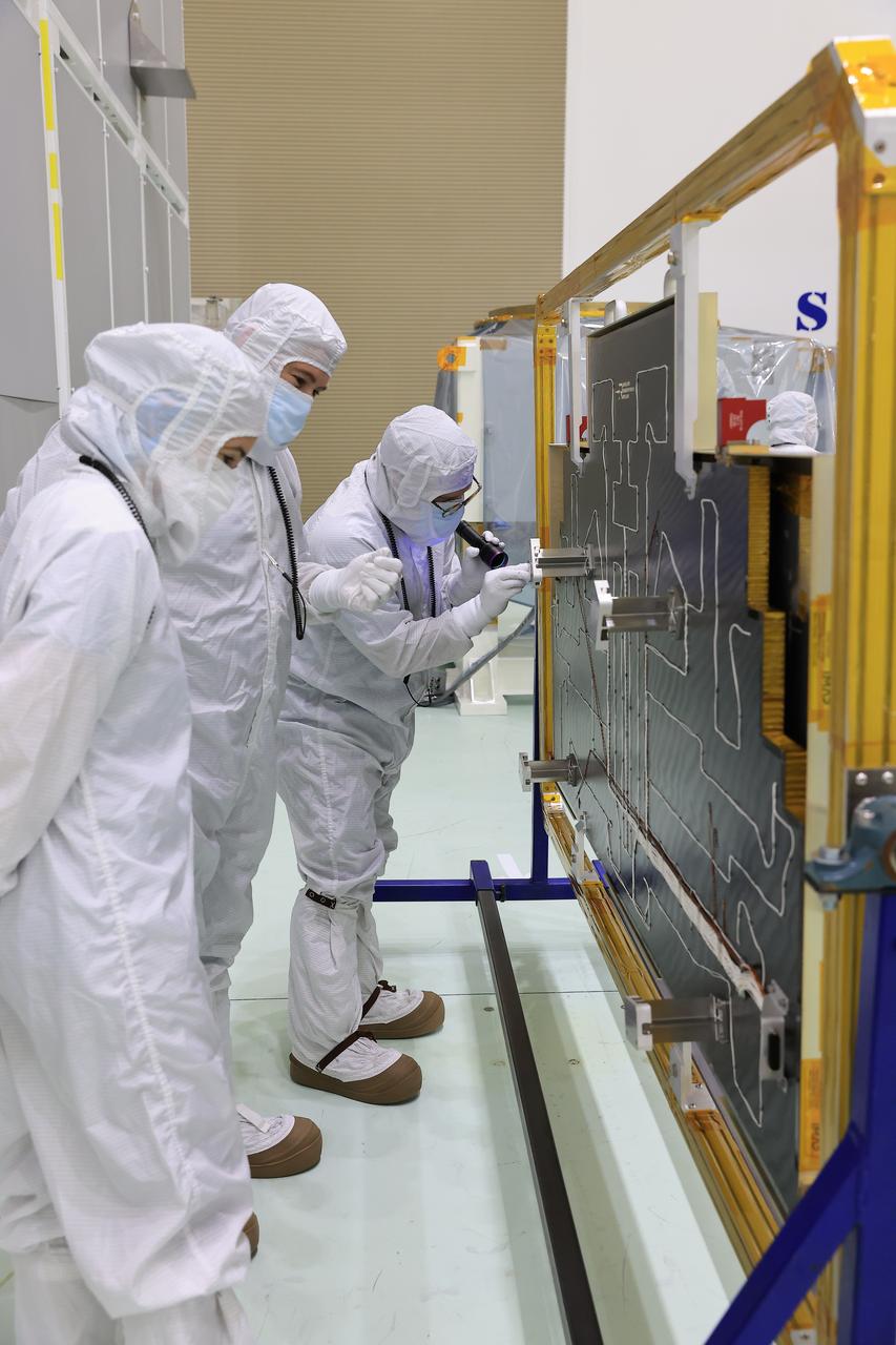
Technicians at the Astrotech Space Operations Facility near NASA’s Kennedy Space Center in Florida remove a protective covering from the two-panel solar array on Friday, July 18, 2025, that will help power the agency’s IMAP (Interstellar Mapping and Acceleration Probe) observatory on its upcoming journey to a destination about one million miles away from Earth at Lagrange Point 1. Each panel of the solar array, located on the top of IMAP, consists of 16 strings of solar cells, with 36 cells per string, and combined will convert sunlight into 500 watts of power, more than enough for the observatory, which as a system uses less power than five 100-watt incandescent light bulbs.
KENNEDY SPACE CENTER, FLA. -- After illumination testing of the solar array panels, technicians begin stowing the panels on the Phoenix Mars Lander spacecraft. The Phoenix will be launched toward Mars to land in icy soils near the planet's north polar permanent ice cap. It will explore the history of the water in these soils and any associated rocks, while monitoring polar climate. Landing on Mars is planned in May 2008 on arctic ground where a mission currently in orbit, Mars Odyssey, has detected high concentrations of ice just beneath the top layer of soil. Phoenix is scheduled to launch Aug. 3 from Pad 17-A at Cape Canaveral Air Force Station . Photo credit: NASA/Kim Shiflett
KENNEDY SPACE CENTER, FLA. -- After illumination testing of the solar array panels, technicians begin stowing the panels on the Phoenix Mars Lander spacecraft. The Phoenix will be launched toward Mars to land in icy soils near the planet's north polar permanent ice cap. It will explore the history of the water in these soils and any associated rocks, while monitoring polar climate. Landing on Mars is planned in May 2008 on arctic ground where a mission currently in orbit, Mars Odyssey, has detected high concentrations of ice just beneath the top layer of soil. Phoenix is scheduled to launch Aug. 3 from Pad 17-A at Cape Canaveral Air Force Station . Photo credit: NASA/Kim Shiflett
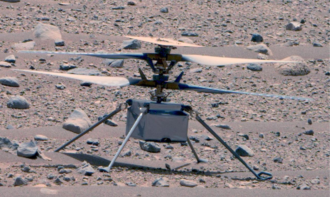
This enhanced color image of NASA's Ingenuity Mars Helicopter was taken by the Mastcam-Z instrument aboard Perseverance on April 16, 2023, the 766th Martian day, or sol, of the rover's mission. At the time the image was taken, the rover was about 75 feet (23 meters) away. The helicopter's first flight on Mars was on April 19, 2021. This is the best look the Ingenuity team has had of the rotorcraft since its first flight. Small diodes (visible more clearly in this image of helicopter) appear as small protrusions on the top of the helicopter's solar panel. The panel and the two 4-foot (1.2-meter) counter-rotating rotors have accumulated a fine coating of dust. The metalized insulating film covering the exterior of the helicopter's fuselage appears to be intact. Ingenuity's color, 13-megapixel, horizon-facing terrain camera can be seen at the center-bottom of the fuselage. https://photojournal.jpl.nasa.gov/catalog/PIA25881
KENNEDY SPACE CENTER, FLA. -- After illumination testing of the solar array panels, technicians complete stowing the panels on the Phoenix Mars Lander spacecraft. The Phoenix will be launched toward Mars to land in icy soils near the planet's north polar permanent ice cap. It will explore the history of the water in these soils and any associated rocks, while monitoring polar climate. Landing on Mars is planned in May 2008 on arctic ground where a mission currently in orbit, Mars Odyssey, has detected high concentrations of ice just beneath the top layer of soil. Phoenix is scheduled to launch Aug. 3 from Pad 17-A at Cape Canaveral Air Force Station . Photo credit: NASA/Kim Shiflett
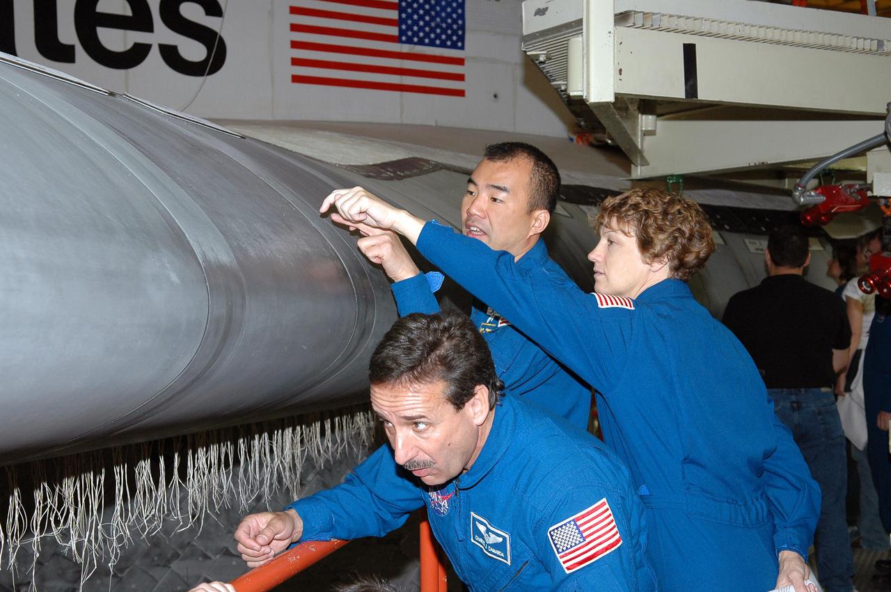
KENNEDY SPACE CENTER, FLA. - In the Orbiter Processing Facility, STS-114 Mission Specialist Charles Camarda looks under the wing leading edge on Discovery while Mission Specialist Soichi Noguchi and Commander Eileen Collins look at an area on top. They and other crew members are at KSC for Crew Equipment Interface Test activities. The leading edge panels of the orbiters’ wings have 22 Reinforced Carbon-Carbon panels, made entirely of carbon composite material. The molded components are approximately 0.25-inch to 0.5-inch thick. During CEIT, the crew has an opportunity to get a hands-on look at the orbiter and equipment they will be working with on the mission. Return to Flight Mission STS-114 will carry the Multi-Purpose Logistics Module Raffaello, filled with supplies for the International Space Station, and a replacement Control Moment Gyroscope. Launch of STS-114 has a launch window of May 12 to June 3.
KENNEDY SPACE CENTER, FLA. -- In the Payload Hazardous Servicing Facility at Cape Canaveral Air Force Station, workers retrieve the springs and bolts from the test firing on the Phoenix Mars Lander spacecraft to deploy the solar panels. The deployment of the panels is part of the pre-launch testing under way. Phoenix will land in icy soils near the north polar permanent ice cap of Mars and explore the history of the water in these soils and any associated rocks, while monitoring polar climate. Landing on Mars is planned in May 2008 on arctic ground where a mission currently in orbit, Mars Odyssey, has detected high concentrations of ice just beneath the top layer of soil. Phoenix is scheduled to launch Aug. 3. Photo credit: NASA/George Shelton
Technicians at the Astrotech Space Operations Facility near NASA’s Kennedy Space Center in Florida conduct illumination testing on Friday, July 18, 2025, by flashing a bright light that simulates the Sun into the two-panel solar array that will help power the agency’s IMAP (Interstellar Mapping and Acceleration Probe) observatory on its upcoming journey to a destination about one million miles away from Earth Lagrange Point 1. Each panel of the solar array, located on the top of IMAP, consists of 16 strings of solar cells, with 36 cells per string, and combined will convert sunlight into 500 watts of power, more than enough for the observatory, which as a system uses less power than five 100-watt incandescent light bulbs.
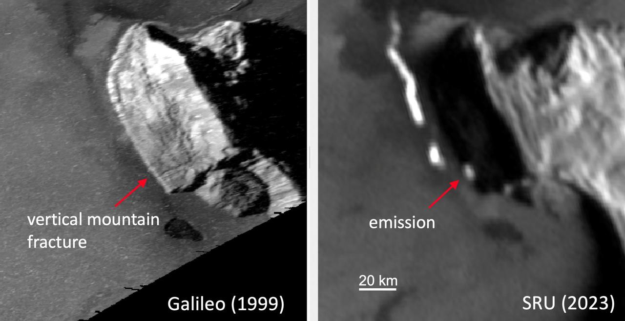
While imaging Io's night side under illumination from Jupiter-shine on Dec. 30, 2023, the Stellar Reference Unit (SRU) on NASA's Juno spacecraft observed an unprecedented glow from active lava at the base of a mountain on Io (red arrow, right panel). The thermal emission signature was located at the base of the western flank of South Zal Mons. Sunlit imagery of the region by captured by NASA's Galileo mission circa 1999 (at left) shows a vertical mountain fracture running from the top of the mountain to the location of the SRU-observed "glow" (red arrow, left panel). One hypothesis is that an extension of the mountain fracture created a fissure vent that allows lava to escape to the surface at this location. https://photojournal.jpl.nasa.gov/catalog/PIA26522
Technicians at the Astrotech Space Operations Facility near NASA’s Kennedy Space Center in Florida conduct illumination testing on Friday, July 18, 2025, by flashing a bright light that simulates the Sun into the two-panel solar array that will help power the agency’s IMAP (Interstellar Mapping and Acceleration Probe) observatory on its upcoming journey to a destination about one million miles away from Earth Lagrange Point 1. Each panel of the solar array, located on the top of IMAP, consists of 16 strings of solar cells, with 36 cells per string, and combined will convert sunlight into 500 watts of power, more than enough for the observatory, which as a system uses less power than five 100-watt incandescent light bulbs.
Standing in Hangar AE, Cape Canaveral Air Station (CCAS) is NASA's Far Ultraviolet Spectroscopic Explorer (FUSE) satellite. The black rectangle on top is the optical port; at the lower right is the solar panel; behind (left) the lower edge of the panel are the radiators. The total length of the instrument is approximately four meters. FUSE was developed by The Johns Hopkins University under contract to Goddard Space Flight Center, Greenbelt, Md., to investigate the origin and evolution of the lightest elements in the universe hydrogen and deuterium. In addition, the FUSE satellite will examine the forces and process involved in the evolution of the galaxies, stars and planetary systems by investigating light in the far ultraviolet portion of the electromagnetic spectrum. Launch is targeted for June 23 from Launch Pad 17A, CCAS, aboard a Boeing Delta II rocket
KENNEDY SPACE CENTER, FLA. - On the side of NASA Kennedy Space Center’s Vehicle Assembly Building, some panels are missing following the wrath of hurricane Wilma as it crossed the state Oct. 24. Kennedy’s facilities sustained minor structural damage, primarily to roofs or from water intrusion. The Vehicle Assembly Building lost some panels on the east and west sides. Some facilities lost power. A total of 13.6 inches of rain was recorded at the Shuttle Landing Facility. The highest wind gust recorded was 94 mph from the north-northwest at Launch Pad 39B, while the maximum sustained wind was 76 mph from the north-northwest at the top of the 492-foot weather tower located north of the Vehicle Assembly Building.
Technicians at the Astrotech Space Operations Facility near NASA’s Kennedy Space Center in Florida conduct illumination testing on Friday, July 18, 2025, by flashing a bright light that simulates the Sun into the two-panel solar array that will help power the agency’s IMAP (Interstellar Mapping and Acceleration Probe) observatory on its upcoming journey to a destination about one million miles away from Earth Lagrange Point 1. Each panel of the solar array, located on the top of IMAP, consists of 16 strings of solar cells, with 36 cells per string, and combined will convert sunlight into 500 watts of power, more than enough for the observatory, which as a system uses less power than five 100-watt incandescent light bulbs.
KENNEDY SPACE CENTER, FLA. -- In the Payload Hazardous Servicing Facility at Cape Canaveral Air Force Station, workers begin unfolding the solar array panels on the Phoenix Mars Lander spacecraft. The deployment of the panels is part of the pre-launch testing under way. Phoenix will land in icy soils near the north polar permanent ice cap of Mars and explore the history of the water in these soils and any associated rocks, while monitoring polar climate. Landing on Mars is planned in May 2008 on arctic ground where a mission currently in orbit, Mars Odyssey, has detected high concentrations of ice just beneath the top layer of soil. Phoenix is scheduled to launch Aug. 3. Photo credit: NASA/George Shelton

Technicians at the Astrotech Space Operations Facility near NASA’s Kennedy Space Center in Florida conduct illumination testing on Friday, July 18, 2025, by flashing a bright light that simulates the Sun into the two-panel solar array that will help power the agency’s IMAP (Interstellar Mapping and Acceleration Probe) observatory on its upcoming journey to a destination about one million miles away from Earth Lagrange Point 1. Each panel of the solar array, located on the top of IMAP, consists of 16 strings of solar cells, with 36 cells per string, and combined will convert sunlight into 500 watts of power, more than enough for the observatory, which as a system uses less power than five 100-watt incandescent light bulbs.
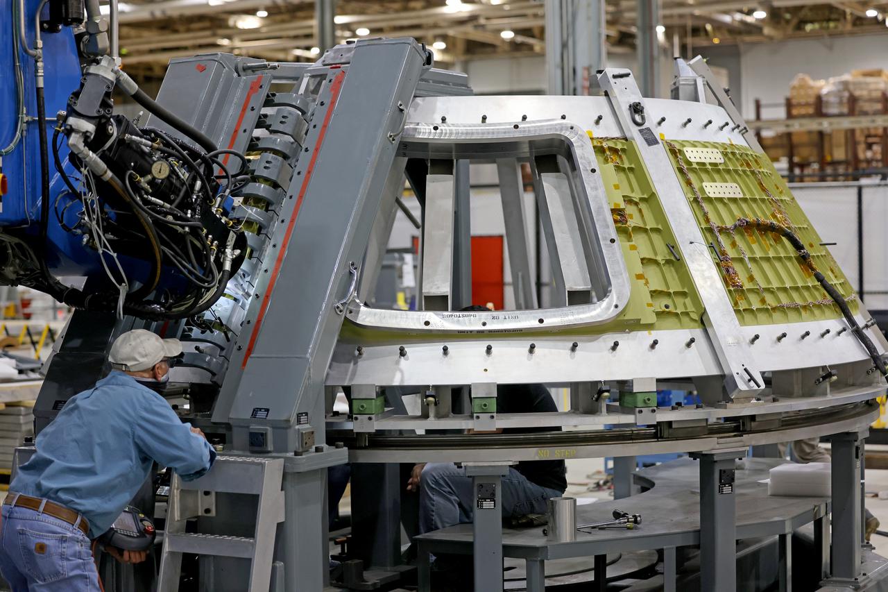
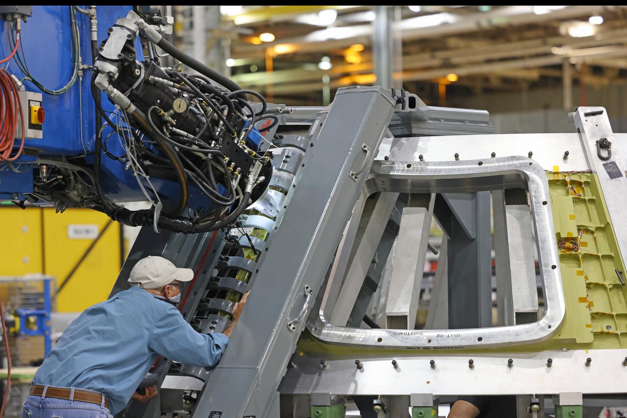
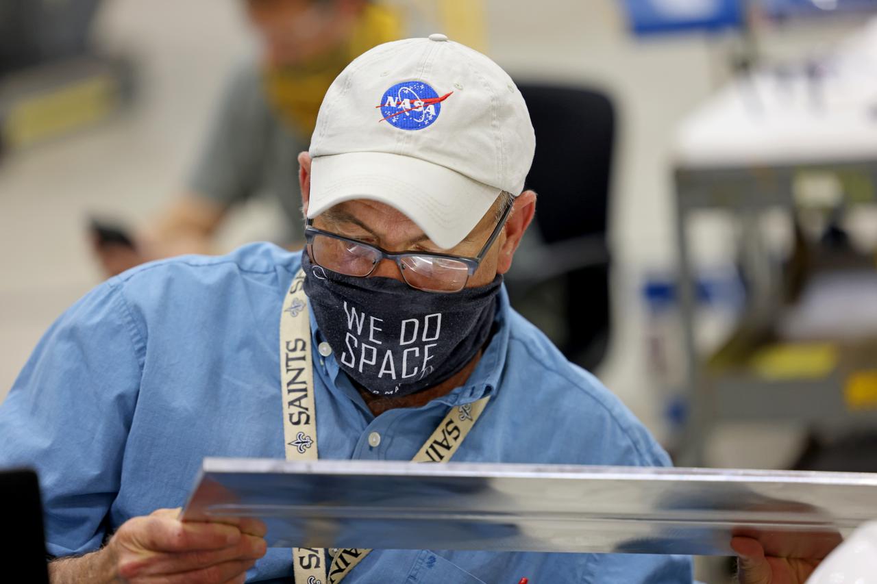
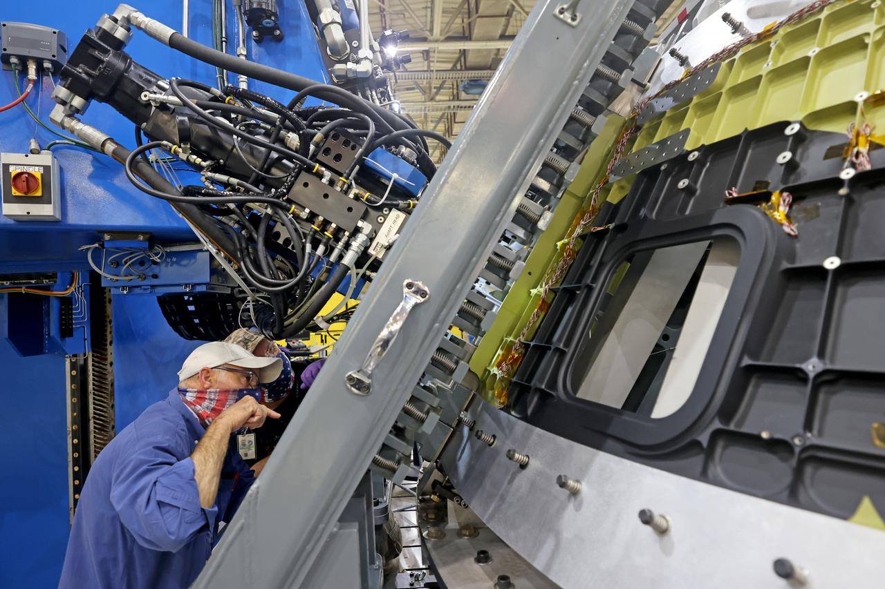
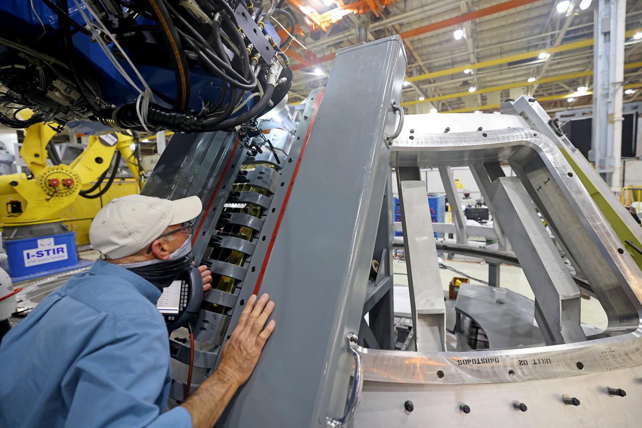
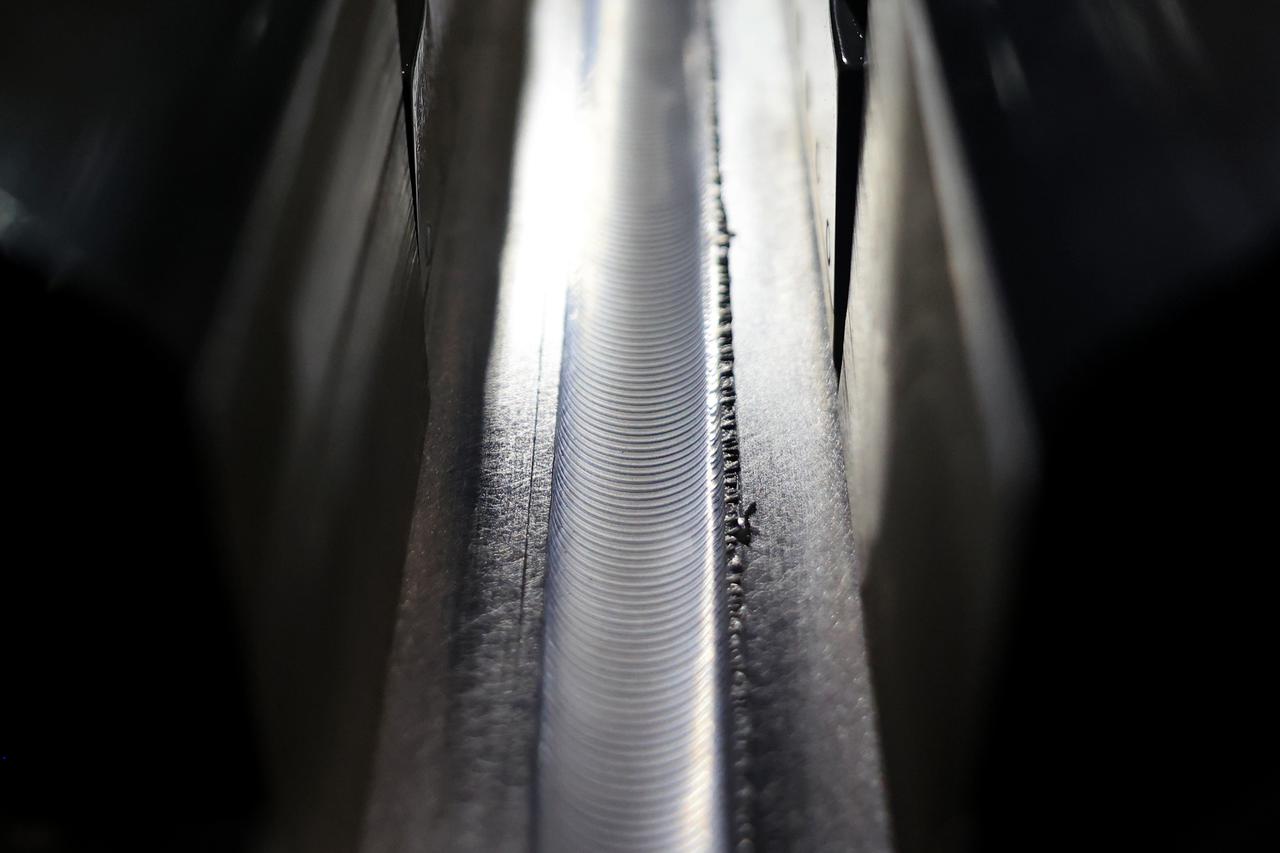
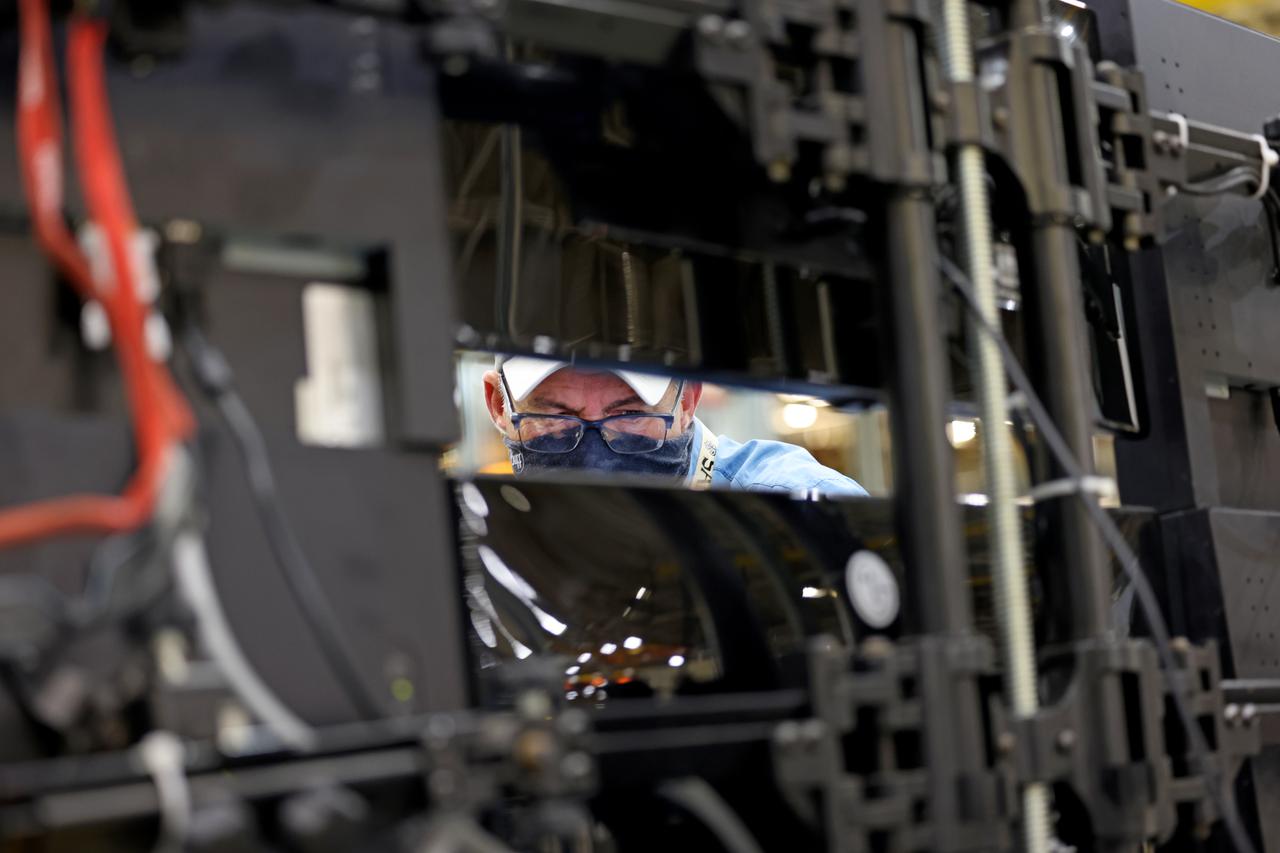
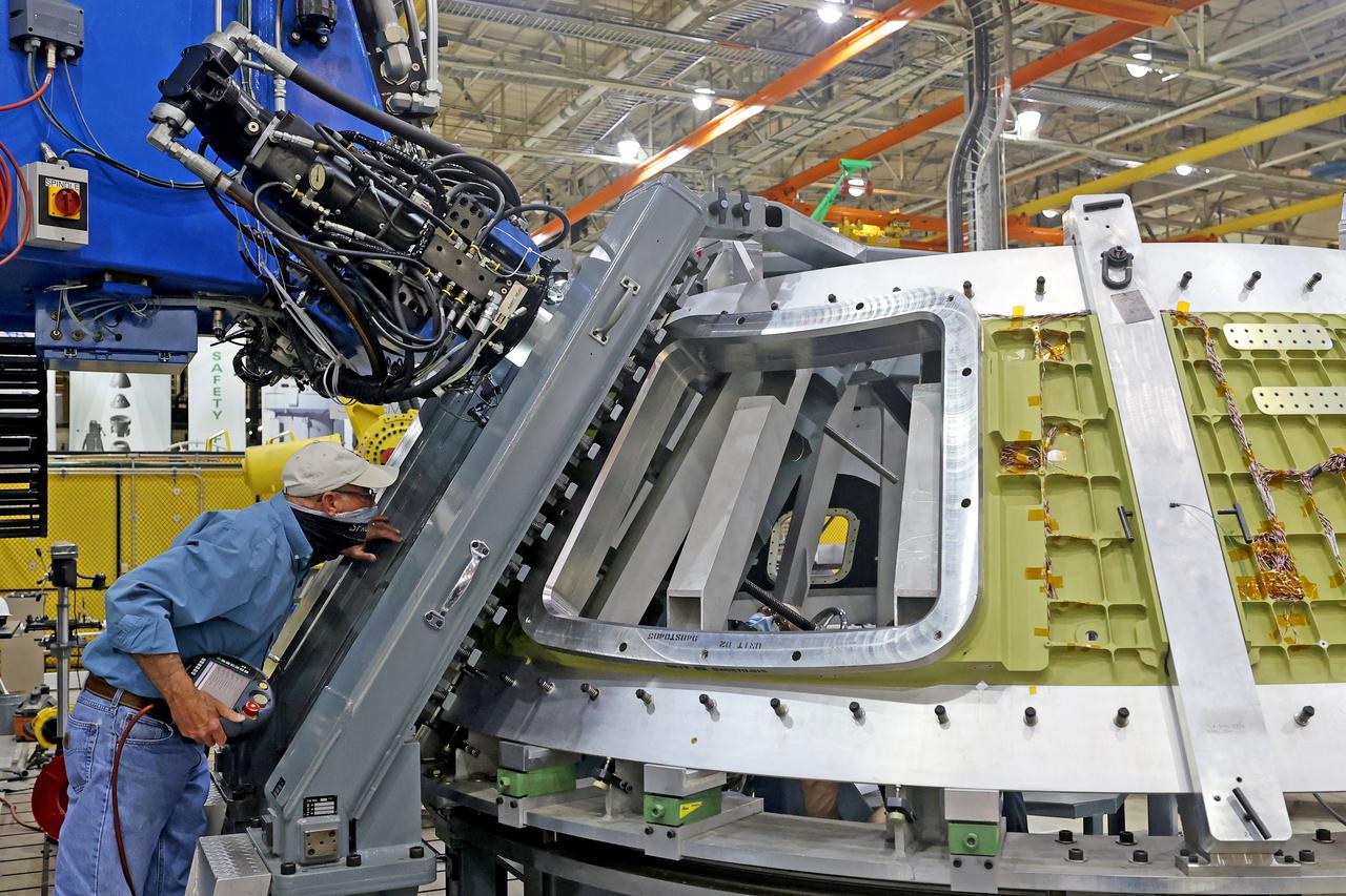
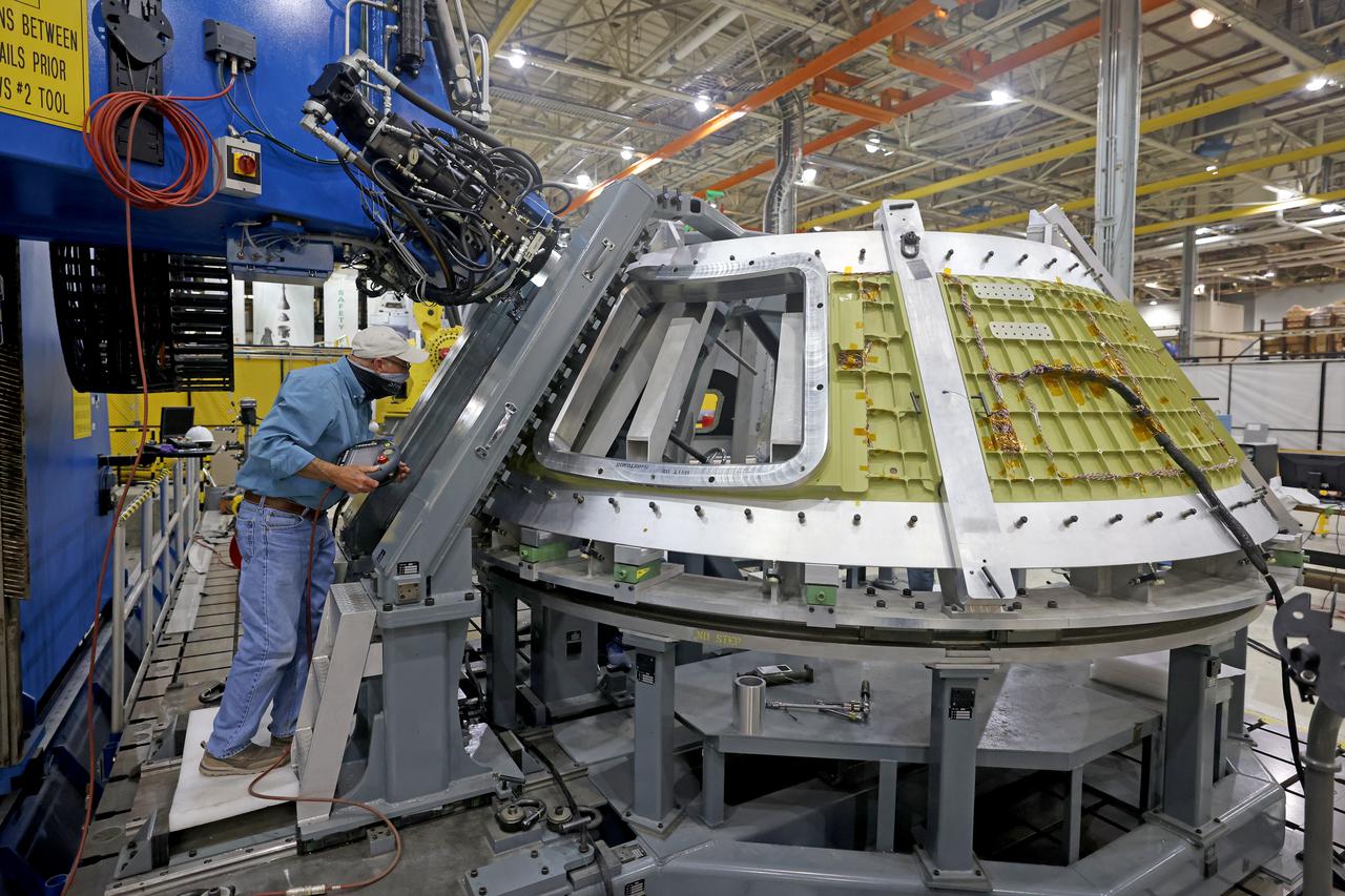
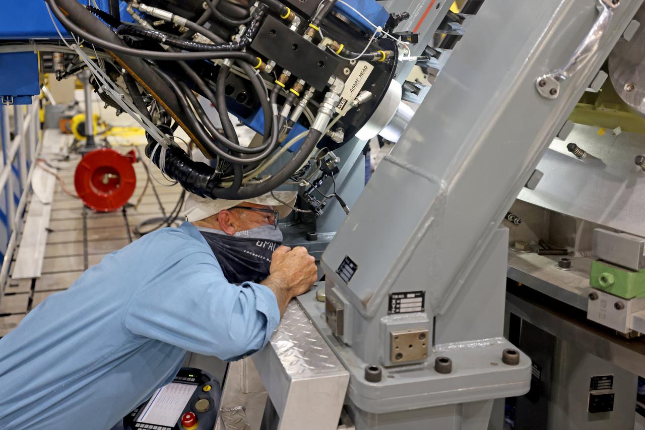
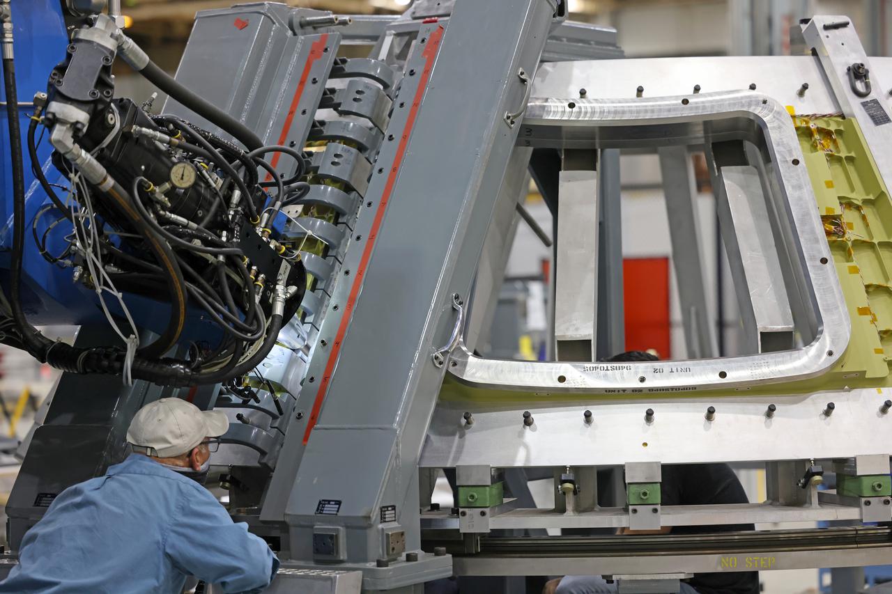
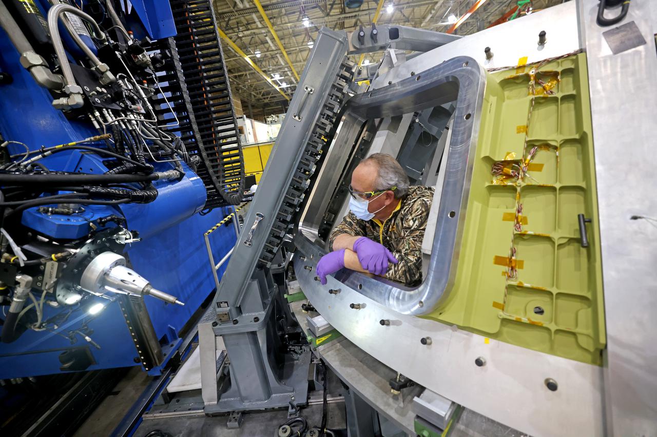
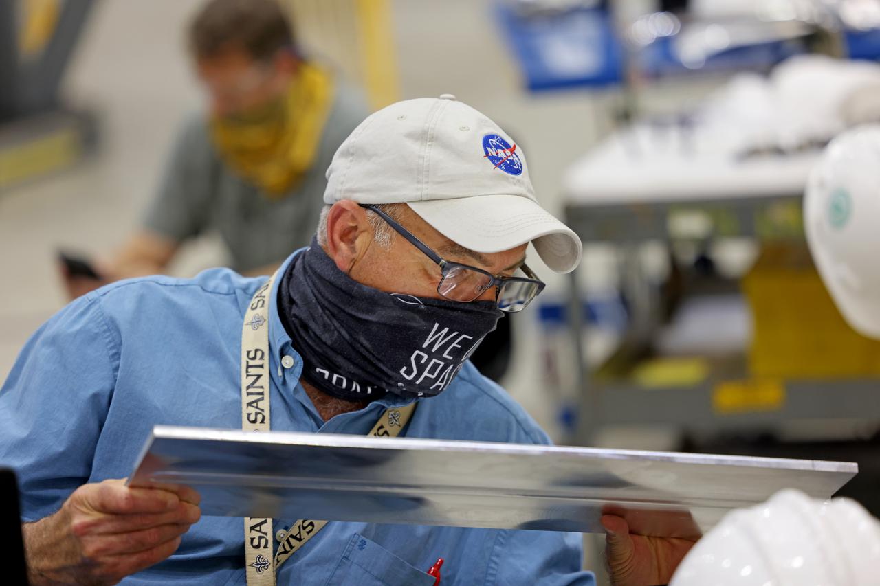
At NASA’s Michoud Assembly Facility in New Orleans, technicians from Orion prime contractor Lockheed Martin have welded together three cone-shaped panels on Orion’s crew module for the Artemis III mission that will land the first woman and next man on the Moon. The crew module’s primary structure, the pressure vessel, is comprised of seven machined aluminum alloy pieces that are welded together through a weld process that produces a strong, air-tight habitable space for astronauts during the mission. The pressure vessel is designed to withstand the harsh and demanding environment of deep space, and is the core structure upon which all the other elements of Orion’s crew module are integrated. Infographic showing the seven pieces of Orion's underlying structure With welding complete on the crew module cone panels – one of which contains windows providing astronauts views of the Moon and Earth – work will begin joining the forward bulkhead to the tunnel to create the top of the spacecraft, followed by the barrel and aft bulkhead join to form the bottom of Orion. Last, the forward bulkhead will be welded to the top of the panels and, for the seventh and closeout weld, the bottom of the cone panels will be joined to the barrel to complete the pressure vessel. Once welding of the Artemis III crew module primary structure is complete, it will be shipped to NASA’s Kennedy Space Center in Florida where it will undergo further assembly beginning this fall. Orion, the Space Launch System, and Exploration Ground Systems programs are foundational elements of the Artemis program. Artemis I will be the first integrated flight test of Orion and SLS and is targeted to launch later this year. Artemis II will follow and is the first crewed mission, taking humans farther into space than ever before. Image credit: NASA/Michael DeMocker
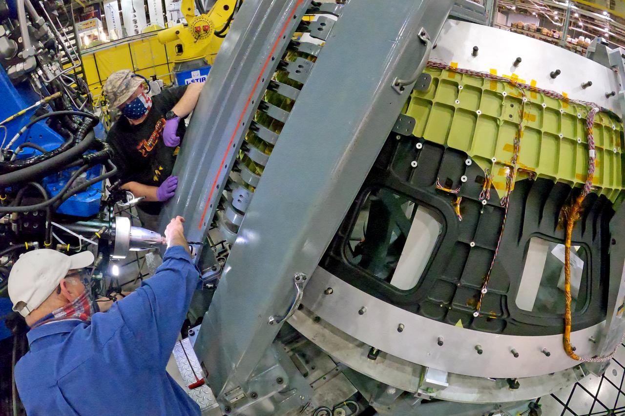
At NASA’s Michoud Assembly Facility in New Orleans, technicians from Orion prime contractor Lockheed Martin have welded together three cone-shaped panels on Orion’s crew module for the Artemis III mission that will land the first woman and next man on the Moon. The crew module’s primary structure, the pressure vessel, is comprised of seven machined aluminum alloy pieces that are welded together through a weld process that produces a strong, air-tight habitable space for astronauts during the mission. The pressure vessel is designed to withstand the harsh and demanding environment of deep space, and is the core structure upon which all the other elements of Orion’s crew module are integrated. Infographic showing the seven pieces of Orion's underlying structure With welding complete on the crew module cone panels – one of which contains windows providing astronauts views of the Moon and Earth – work will begin joining the forward bulkhead to the tunnel to create the top of the spacecraft, followed by the barrel and aft bulkhead join to form the bottom of Orion. Last, the forward bulkhead will be welded to the top of the panels and, for the seventh and closeout weld, the bottom of the cone panels will be joined to the barrel to complete the pressure vessel. Once welding of the Artemis III crew module primary structure is complete, it will be shipped to NASA’s Kennedy Space Center in Florida where it will undergo further assembly beginning this fall. Orion, the Space Launch System, and Exploration Ground Systems programs are foundational elements of the Artemis program. Artemis I will be the first integrated flight test of Orion and SLS and is targeted to launch later this year. Artemis II will follow and is the first crewed mission, taking humans farther into space than ever before. Image credit: NASA/Michael DeMocker
At NASA’s Michoud Assembly Facility in New Orleans, technicians from Orion prime contractor Lockheed Martin have welded together three cone-shaped panels on Orion’s crew module for the Artemis III mission that will land the first woman and next man on the Moon. The crew module’s primary structure, the pressure vessel, is comprised of seven machined aluminum alloy pieces that are welded together through a weld process that produces a strong, air-tight habitable space for astronauts during the mission. The pressure vessel is designed to withstand the harsh and demanding environment of deep space, and is the core structure upon which all the other elements of Orion’s crew module are integrated. Infographic showing the seven pieces of Orion's underlying structure With welding complete on the crew module cone panels – one of which contains windows providing astronauts views of the Moon and Earth – work will begin joining the forward bulkhead to the tunnel to create the top of the spacecraft, followed by the barrel and aft bulkhead join to form the bottom of Orion. Last, the forward bulkhead will be welded to the top of the panels and, for the seventh and closeout weld, the bottom of the cone panels will be joined to the barrel to complete the pressure vessel. Once welding of the Artemis III crew module primary structure is complete, it will be shipped to NASA’s Kennedy Space Center in Florida where it will undergo further assembly beginning this fall. Orion, the Space Launch System, and Exploration Ground Systems programs are foundational elements of the Artemis program. Artemis I will be the first integrated flight test of Orion and SLS and is targeted to launch later this year. Artemis II will follow and is the first crewed mission, taking humans farther into space than ever before. Image credit: NASA/Michael DeMocker
At NASA’s Michoud Assembly Facility in New Orleans, technicians from Orion prime contractor Lockheed Martin have welded together three cone-shaped panels on Orion’s crew module for the Artemis III mission that will land the first woman and next man on the Moon. The crew module’s primary structure, the pressure vessel, is comprised of seven machined aluminum alloy pieces that are welded together through a weld process that produces a strong, air-tight habitable space for astronauts during the mission. The pressure vessel is designed to withstand the harsh and demanding environment of deep space, and is the core structure upon which all the other elements of Orion’s crew module are integrated. Infographic showing the seven pieces of Orion's underlying structure With welding complete on the crew module cone panels – one of which contains windows providing astronauts views of the Moon and Earth – work will begin joining the forward bulkhead to the tunnel to create the top of the spacecraft, followed by the barrel and aft bulkhead join to form the bottom of Orion. Last, the forward bulkhead will be welded to the top of the panels and, for the seventh and closeout weld, the bottom of the cone panels will be joined to the barrel to complete the pressure vessel. Once welding of the Artemis III crew module primary structure is complete, it will be shipped to NASA’s Kennedy Space Center in Florida where it will undergo further assembly beginning this fall. Orion, the Space Launch System, and Exploration Ground Systems programs are foundational elements of the Artemis program. Artemis I will be the first integrated flight test of Orion and SLS and is targeted to launch later this year. Artemis II will follow and is the first crewed mission, taking humans farther into space than ever before. Image credit: NASA/Michael DeMocker
At NASA’s Michoud Assembly Facility in New Orleans, technicians from Orion prime contractor Lockheed Martin have welded together three cone-shaped panels on Orion’s crew module for the Artemis III mission that will land the first woman and next man on the Moon. The crew module’s primary structure, the pressure vessel, is comprised of seven machined aluminum alloy pieces that are welded together through a weld process that produces a strong, air-tight habitable space for astronauts during the mission. The pressure vessel is designed to withstand the harsh and demanding environment of deep space, and is the core structure upon which all the other elements of Orion’s crew module are integrated. Infographic showing the seven pieces of Orion's underlying structure With welding complete on the crew module cone panels – one of which contains windows providing astronauts views of the Moon and Earth – work will begin joining the forward bulkhead to the tunnel to create the top of the spacecraft, followed by the barrel and aft bulkhead join to form the bottom of Orion. Last, the forward bulkhead will be welded to the top of the panels and, for the seventh and closeout weld, the bottom of the cone panels will be joined to the barrel to complete the pressure vessel. Once welding of the Artemis III crew module primary structure is complete, it will be shipped to NASA’s Kennedy Space Center in Florida where it will undergo further assembly beginning this fall. Orion, the Space Launch System, and Exploration Ground Systems programs are foundational elements of the Artemis program. Artemis I will be the first integrated flight test of Orion and SLS and is targeted to launch later this year. Artemis II will follow and is the first crewed mission, taking humans farther into space than ever before. Image credit: NASA/Michael DeMocker
At NASA’s Michoud Assembly Facility in New Orleans, technicians from Orion prime contractor Lockheed Martin have welded together three cone-shaped panels on Orion’s crew module for the Artemis III mission that will land the first woman and next man on the Moon. The crew module’s primary structure, the pressure vessel, is comprised of seven machined aluminum alloy pieces that are welded together through a weld process that produces a strong, air-tight habitable space for astronauts during the mission. The pressure vessel is designed to withstand the harsh and demanding environment of deep space, and is the core structure upon which all the other elements of Orion’s crew module are integrated. Infographic showing the seven pieces of Orion's underlying structure With welding complete on the crew module cone panels – one of which contains windows providing astronauts views of the Moon and Earth – work will begin joining the forward bulkhead to the tunnel to create the top of the spacecraft, followed by the barrel and aft bulkhead join to form the bottom of Orion. Last, the forward bulkhead will be welded to the top of the panels and, for the seventh and closeout weld, the bottom of the cone panels will be joined to the barrel to complete the pressure vessel. Once welding of the Artemis III crew module primary structure is complete, it will be shipped to NASA’s Kennedy Space Center in Florida where it will undergo further assembly beginning this fall. Orion, the Space Launch System, and Exploration Ground Systems programs are foundational elements of the Artemis program. Artemis I will be the first integrated flight test of Orion and SLS and is targeted to launch later this year. Artemis II will follow and is the first crewed mission, taking humans farther into space than ever before. Image credit: NASA/Michael DeMocker
At NASA’s Michoud Assembly Facility in New Orleans, technicians from Orion prime contractor Lockheed Martin have welded together three cone-shaped panels on Orion’s crew module for the Artemis III mission that will land the first woman and next man on the Moon. The crew module’s primary structure, the pressure vessel, is comprised of seven machined aluminum alloy pieces that are welded together through a weld process that produces a strong, air-tight habitable space for astronauts during the mission. The pressure vessel is designed to withstand the harsh and demanding environment of deep space, and is the core structure upon which all the other elements of Orion’s crew module are integrated. Infographic showing the seven pieces of Orion's underlying structure With welding complete on the crew module cone panels – one of which contains windows providing astronauts views of the Moon and Earth – work will begin joining the forward bulkhead to the tunnel to create the top of the spacecraft, followed by the barrel and aft bulkhead join to form the bottom of Orion. Last, the forward bulkhead will be welded to the top of the panels and, for the seventh and closeout weld, the bottom of the cone panels will be joined to the barrel to complete the pressure vessel. Once welding of the Artemis III crew module primary structure is complete, it will be shipped to NASA’s Kennedy Space Center in Florida where it will undergo further assembly beginning this fall. Orion, the Space Launch System, and Exploration Ground Systems programs are foundational elements of the Artemis program. Artemis I will be the first integrated flight test of Orion and SLS and is targeted to launch later this year. Artemis II will follow and is the first crewed mission, taking humans farther into space than ever before. Image credit: NASA/Michael DeMocker
At NASA’s Michoud Assembly Facility in New Orleans, technicians from Orion prime contractor Lockheed Martin have welded together three cone-shaped panels on Orion’s crew module for the Artemis III mission that will land the first woman and next man on the Moon. The crew module’s primary structure, the pressure vessel, is comprised of seven machined aluminum alloy pieces that are welded together through a weld process that produces a strong, air-tight habitable space for astronauts during the mission. The pressure vessel is designed to withstand the harsh and demanding environment of deep space, and is the core structure upon which all the other elements of Orion’s crew module are integrated. Infographic showing the seven pieces of Orion's underlying structure With welding complete on the crew module cone panels – one of which contains windows providing astronauts views of the Moon and Earth – work will begin joining the forward bulkhead to the tunnel to create the top of the spacecraft, followed by the barrel and aft bulkhead join to form the bottom of Orion. Last, the forward bulkhead will be welded to the top of the panels and, for the seventh and closeout weld, the bottom of the cone panels will be joined to the barrel to complete the pressure vessel. Once welding of the Artemis III crew module primary structure is complete, it will be shipped to NASA’s Kennedy Space Center in Florida where it will undergo further assembly beginning this fall. Orion, the Space Launch System, and Exploration Ground Systems programs are foundational elements of the Artemis program. Artemis I will be the first integrated flight test of Orion and SLS and is targeted to launch later this year. Artemis II will follow and is the first crewed mission, taking humans farther into space than ever before. Image credit: NASA/Michael DeMocker
At NASA’s Michoud Assembly Facility in New Orleans, technicians from Orion prime contractor Lockheed Martin have welded together three cone-shaped panels on Orion’s crew module for the Artemis III mission that will land the first woman and next man on the Moon. The crew module’s primary structure, the pressure vessel, is comprised of seven machined aluminum alloy pieces that are welded together through a weld process that produces a strong, air-tight habitable space for astronauts during the mission. The pressure vessel is designed to withstand the harsh and demanding environment of deep space, and is the core structure upon which all the other elements of Orion’s crew module are integrated. Infographic showing the seven pieces of Orion's underlying structure With welding complete on the crew module cone panels – one of which contains windows providing astronauts views of the Moon and Earth – work will begin joining the forward bulkhead to the tunnel to create the top of the spacecraft, followed by the barrel and aft bulkhead join to form the bottom of Orion. Last, the forward bulkhead will be welded to the top of the panels and, for the seventh and closeout weld, the bottom of the cone panels will be joined to the barrel to complete the pressure vessel. Once welding of the Artemis III crew module primary structure is complete, it will be shipped to NASA’s Kennedy Space Center in Florida where it will undergo further assembly beginning this fall. Orion, the Space Launch System, and Exploration Ground Systems programs are foundational elements of the Artemis program. Artemis I will be the first integrated flight test of Orion and SLS and is targeted to launch later this year. Artemis II will follow and is the first crewed mission, taking humans farther into space than ever before. Image credit: NASA/Michael DeMocker
At NASA’s Michoud Assembly Facility in New Orleans, technicians from Orion prime contractor Lockheed Martin have welded together three cone-shaped panels on Orion’s crew module for the Artemis III mission that will land the first woman and next man on the Moon. The crew module’s primary structure, the pressure vessel, is comprised of seven machined aluminum alloy pieces that are welded together through a weld process that produces a strong, air-tight habitable space for astronauts during the mission. The pressure vessel is designed to withstand the harsh and demanding environment of deep space, and is the core structure upon which all the other elements of Orion’s crew module are integrated. Infographic showing the seven pieces of Orion's underlying structure With welding complete on the crew module cone panels – one of which contains windows providing astronauts views of the Moon and Earth – work will begin joining the forward bulkhead to the tunnel to create the top of the spacecraft, followed by the barrel and aft bulkhead join to form the bottom of Orion. Last, the forward bulkhead will be welded to the top of the panels and, for the seventh and closeout weld, the bottom of the cone panels will be joined to the barrel to complete the pressure vessel. Once welding of the Artemis III crew module primary structure is complete, it will be shipped to NASA’s Kennedy Space Center in Florida where it will undergo further assembly beginning this fall. Orion, the Space Launch System, and Exploration Ground Systems programs are foundational elements of the Artemis program. Artemis I will be the first integrated flight test of Orion and SLS and is targeted to launch later this year. Artemis II will follow and is the first crewed mission, taking humans farther into space than ever before. Image credit: NASA/Michael DeMocker
At NASA’s Michoud Assembly Facility in New Orleans, technicians from Orion prime contractor Lockheed Martin have welded together three cone-shaped panels on Orion’s crew module for the Artemis III mission that will land the first woman and next man on the Moon. The crew module’s primary structure, the pressure vessel, is comprised of seven machined aluminum alloy pieces that are welded together through a weld process that produces a strong, air-tight habitable space for astronauts during the mission. The pressure vessel is designed to withstand the harsh and demanding environment of deep space, and is the core structure upon which all the other elements of Orion’s crew module are integrated. Infographic showing the seven pieces of Orion's underlying structure With welding complete on the crew module cone panels – one of which contains windows providing astronauts views of the Moon and Earth – work will begin joining the forward bulkhead to the tunnel to create the top of the spacecraft, followed by the barrel and aft bulkhead join to form the bottom of Orion. Last, the forward bulkhead will be welded to the top of the panels and, for the seventh and closeout weld, the bottom of the cone panels will be joined to the barrel to complete the pressure vessel. Once welding of the Artemis III crew module primary structure is complete, it will be shipped to NASA’s Kennedy Space Center in Florida where it will undergo further assembly beginning this fall. Orion, the Space Launch System, and Exploration Ground Systems programs are foundational elements of the Artemis program. Artemis I will be the first integrated flight test of Orion and SLS and is targeted to launch later this year. Artemis II will follow and is the first crewed mission, taking humans farther into space than ever before. Image credit: NASA/Michael DeMocker
At NASA’s Michoud Assembly Facility in New Orleans, technicians from Orion prime contractor Lockheed Martin have welded together three cone-shaped panels on Orion’s crew module for the Artemis III mission that will land the first woman and next man on the Moon. The crew module’s primary structure, the pressure vessel, is comprised of seven machined aluminum alloy pieces that are welded together through a weld process that produces a strong, air-tight habitable space for astronauts during the mission. The pressure vessel is designed to withstand the harsh and demanding environment of deep space, and is the core structure upon which all the other elements of Orion’s crew module are integrated. Infographic showing the seven pieces of Orion's underlying structure With welding complete on the crew module cone panels – one of which contains windows providing astronauts views of the Moon and Earth – work will begin joining the forward bulkhead to the tunnel to create the top of the spacecraft, followed by the barrel and aft bulkhead join to form the bottom of Orion. Last, the forward bulkhead will be welded to the top of the panels and, for the seventh and closeout weld, the bottom of the cone panels will be joined to the barrel to complete the pressure vessel. Once welding of the Artemis III crew module primary structure is complete, it will be shipped to NASA’s Kennedy Space Center in Florida where it will undergo further assembly beginning this fall. Orion, the Space Launch System, and Exploration Ground Systems programs are foundational elements of the Artemis program. Artemis I will be the first integrated flight test of Orion and SLS and is targeted to launch later this year. Artemis II will follow and is the first crewed mission, taking humans farther into space than ever before. Image credit: NASA/Michael DeMocker
At NASA’s Michoud Assembly Facility in New Orleans, technicians from Orion prime contractor Lockheed Martin have welded together three cone-shaped panels on Orion’s crew module for the Artemis III mission that will land the first woman and next man on the Moon. The crew module’s primary structure, the pressure vessel, is comprised of seven machined aluminum alloy pieces that are welded together through a weld process that produces a strong, air-tight habitable space for astronauts during the mission. The pressure vessel is designed to withstand the harsh and demanding environment of deep space, and is the core structure upon which all the other elements of Orion’s crew module are integrated. Infographic showing the seven pieces of Orion's underlying structure With welding complete on the crew module cone panels – one of which contains windows providing astronauts views of the Moon and Earth – work will begin joining the forward bulkhead to the tunnel to create the top of the spacecraft, followed by the barrel and aft bulkhead join to form the bottom of Orion. Last, the forward bulkhead will be welded to the top of the panels and, for the seventh and closeout weld, the bottom of the cone panels will be joined to the barrel to complete the pressure vessel. Once welding of the Artemis III crew module primary structure is complete, it will be shipped to NASA’s Kennedy Space Center in Florida where it will undergo further assembly beginning this fall. Orion, the Space Launch System, and Exploration Ground Systems programs are foundational elements of the Artemis program. Artemis I will be the first integrated flight test of Orion and SLS and is targeted to launch later this year. Artemis II will follow and is the first crewed mission, taking humans farther into space than ever before. Image credit: NASA/Michael DeMocker
At NASA’s Michoud Assembly Facility in New Orleans, technicians from Orion prime contractor Lockheed Martin have welded together three cone-shaped panels on Orion’s crew module for the Artemis III mission that will land the first woman and next man on the Moon. The crew module’s primary structure, the pressure vessel, is comprised of seven machined aluminum alloy pieces that are welded together through a weld process that produces a strong, air-tight habitable space for astronauts during the mission. The pressure vessel is designed to withstand the harsh and demanding environment of deep space, and is the core structure upon which all the other elements of Orion’s crew module are integrated. Infographic showing the seven pieces of Orion's underlying structure With welding complete on the crew module cone panels – one of which contains windows providing astronauts views of the Moon and Earth – work will begin joining the forward bulkhead to the tunnel to create the top of the spacecraft, followed by the barrel and aft bulkhead join to form the bottom of Orion. Last, the forward bulkhead will be welded to the top of the panels and, for the seventh and closeout weld, the bottom of the cone panels will be joined to the barrel to complete the pressure vessel. Once welding of the Artemis III crew module primary structure is complete, it will be shipped to NASA’s Kennedy Space Center in Florida where it will undergo further assembly beginning this fall. Orion, the Space Launch System, and Exploration Ground Systems programs are foundational elements of the Artemis program. Artemis I will be the first integrated flight test of Orion and SLS and is targeted to launch later this year. Artemis II will follow and is the first crewed mission, taking humans farther into space than ever before. Image credit: NASA/Michael DeMocker
At NASA’s Michoud Assembly Facility in New Orleans, technicians from Orion prime contractor Lockheed Martin have welded together three cone-shaped panels on Orion’s crew module for the Artemis III mission that will land the first woman and next man on the Moon. The crew module’s primary structure, the pressure vessel, is comprised of seven machined aluminum alloy pieces that are welded together through a weld process that produces a strong, air-tight habitable space for astronauts during the mission. The pressure vessel is designed to withstand the harsh and demanding environment of deep space, and is the core structure upon which all the other elements of Orion’s crew module are integrated. Infographic showing the seven pieces of Orion's underlying structure With welding complete on the crew module cone panels – one of which contains windows providing astronauts views of the Moon and Earth – work will begin joining the forward bulkhead to the tunnel to create the top of the spacecraft, followed by the barrel and aft bulkhead join to form the bottom of Orion. Last, the forward bulkhead will be welded to the top of the panels and, for the seventh and closeout weld, the bottom of the cone panels will be joined to the barrel to complete the pressure vessel. Once welding of the Artemis III crew module primary structure is complete, it will be shipped to NASA’s Kennedy Space Center in Florida where it will undergo further assembly beginning this fall. Orion, the Space Launch System, and Exploration Ground Systems programs are foundational elements of the Artemis program. Artemis I will be the first integrated flight test of Orion and SLS and is targeted to launch later this year. Artemis II will follow and is the first crewed mission, taking humans farther into space than ever before. Image credit: NASA/Michael DeMocker
At NASA’s Michoud Assembly Facility in New Orleans, technicians from Orion prime contractor Lockheed Martin have welded together three cone-shaped panels on Orion’s crew module for the Artemis III mission that will land the first woman and next man on the Moon. The crew module’s primary structure, the pressure vessel, is comprised of seven machined aluminum alloy pieces that are welded together through a weld process that produces a strong, air-tight habitable space for astronauts during the mission. The pressure vessel is designed to withstand the harsh and demanding environment of deep space, and is the core structure upon which all the other elements of Orion’s crew module are integrated. Infographic showing the seven pieces of Orion's underlying structure With welding complete on the crew module cone panels – one of which contains windows providing astronauts views of the Moon and Earth – work will begin joining the forward bulkhead to the tunnel to create the top of the spacecraft, followed by the barrel and aft bulkhead join to form the bottom of Orion. Last, the forward bulkhead will be welded to the top of the panels and, for the seventh and closeout weld, the bottom of the cone panels will be joined to the barrel to complete the pressure vessel. Once welding of the Artemis III crew module primary structure is complete, it will be shipped to NASA’s Kennedy Space Center in Florida where it will undergo further assembly beginning this fall. Orion, the Space Launch System, and Exploration Ground Systems programs are foundational elements of the Artemis program. Artemis I will be the first integrated flight test of Orion and SLS and is targeted to launch later this year. Artemis II will follow and is the first crewed mission, taking humans farther into space than ever before. Image credit: NASA/Michael DeMocker
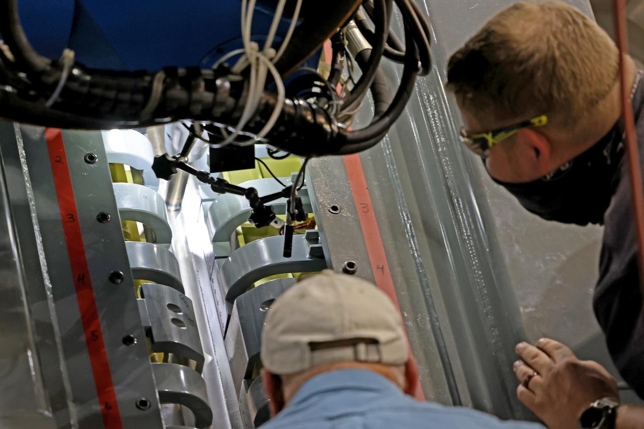
At NASA’s Michoud Assembly Facility in New Orleans, technicians from Orion prime contractor Lockheed Martin have welded together three cone-shaped panels on Orion’s crew module for the Artemis III mission that will land the first woman and next man on the Moon. The crew module’s primary structure, the pressure vessel, is comprised of seven machined aluminum alloy pieces that are welded together through a weld process that produces a strong, air-tight habitable space for astronauts during the mission. The pressure vessel is designed to withstand the harsh and demanding environment of deep space, and is the core structure upon which all the other elements of Orion’s crew module are integrated. Infographic showing the seven pieces of Orion's underlying structure With welding complete on the crew module cone panels – one of which contains windows providing astronauts views of the Moon and Earth – work will begin joining the forward bulkhead to the tunnel to create the top of the spacecraft, followed by the barrel and aft bulkhead join to form the bottom of Orion. Last, the forward bulkhead will be welded to the top of the panels and, for the seventh and closeout weld, the bottom of the cone panels will be joined to the barrel to complete the pressure vessel. Once welding of the Artemis III crew module primary structure is complete, it will be shipped to NASA’s Kennedy Space Center in Florida where it will undergo further assembly beginning this fall. Orion, the Space Launch System, and Exploration Ground Systems programs are foundational elements of the Artemis program. Artemis I will be the first integrated flight test of Orion and SLS and is targeted to launch later this year. Artemis II will follow and is the first crewed mission, taking humans farther into space than ever before. Image credit: NASA/Michael DeMocker
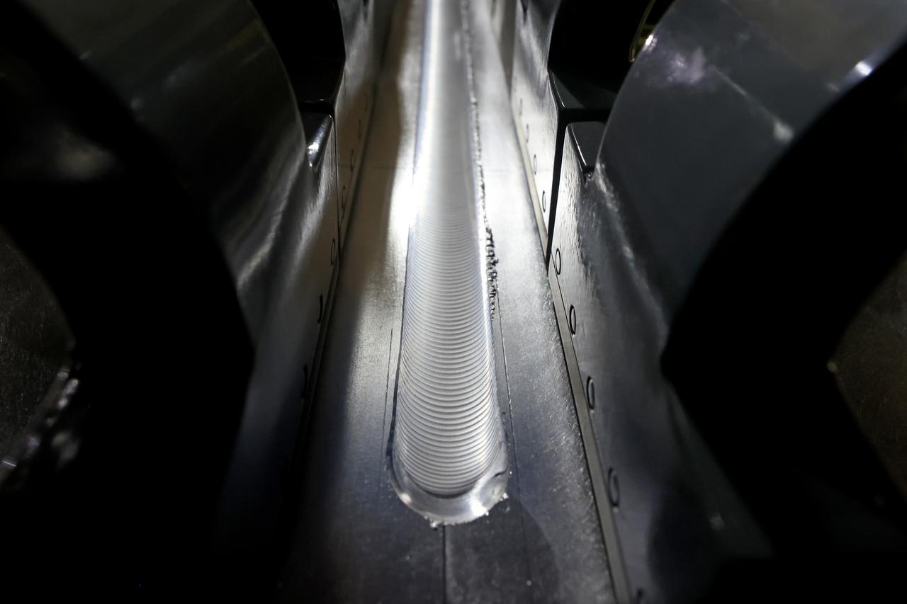
At NASA’s Michoud Assembly Facility in New Orleans, technicians from Orion prime contractor Lockheed Martin have welded together three cone-shaped panels on Orion’s crew module for the Artemis III mission that will land the first woman and next man on the Moon. The crew module’s primary structure, the pressure vessel, is comprised of seven machined aluminum alloy pieces that are welded together through a weld process that produces a strong, air-tight habitable space for astronauts during the mission. The pressure vessel is designed to withstand the harsh and demanding environment of deep space, and is the core structure upon which all the other elements of Orion’s crew module are integrated. Infographic showing the seven pieces of Orion's underlying structure With welding complete on the crew module cone panels – one of which contains windows providing astronauts views of the Moon and Earth – work will begin joining the forward bulkhead to the tunnel to create the top of the spacecraft, followed by the barrel and aft bulkhead join to form the bottom of Orion. Last, the forward bulkhead will be welded to the top of the panels and, for the seventh and closeout weld, the bottom of the cone panels will be joined to the barrel to complete the pressure vessel. Once welding of the Artemis III crew module primary structure is complete, it will be shipped to NASA’s Kennedy Space Center in Florida where it will undergo further assembly beginning this fall. Orion, the Space Launch System, and Exploration Ground Systems programs are foundational elements of the Artemis program. Artemis I will be the first integrated flight test of Orion and SLS and is targeted to launch later this year. Artemis II will follow and is the first crewed mission, taking humans farther into space than ever before. Image credit: NASA/Michael DeMocker
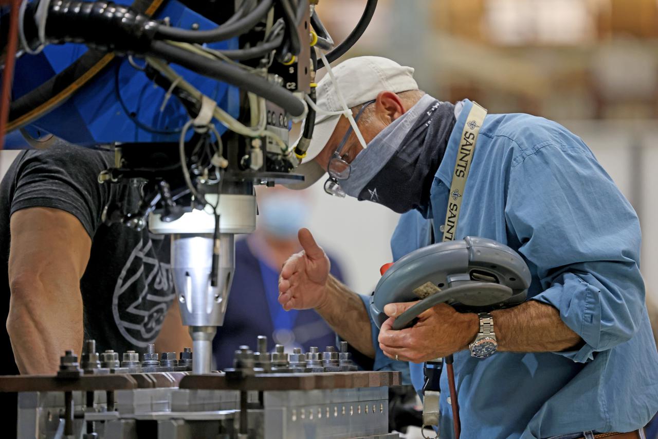
At NASA’s Michoud Assembly Facility in New Orleans, technicians from Orion prime contractor Lockheed Martin have welded together three cone-shaped panels on Orion’s crew module for the Artemis III mission that will land the first woman and next man on the Moon. The crew module’s primary structure, the pressure vessel, is comprised of seven machined aluminum alloy pieces that are welded together through a weld process that produces a strong, air-tight habitable space for astronauts during the mission. The pressure vessel is designed to withstand the harsh and demanding environment of deep space, and is the core structure upon which all the other elements of Orion’s crew module are integrated. Infographic showing the seven pieces of Orion's underlying structure With welding complete on the crew module cone panels – one of which contains windows providing astronauts views of the Moon and Earth – work will begin joining the forward bulkhead to the tunnel to create the top of the spacecraft, followed by the barrel and aft bulkhead join to form the bottom of Orion. Last, the forward bulkhead will be welded to the top of the panels and, for the seventh and closeout weld, the bottom of the cone panels will be joined to the barrel to complete the pressure vessel. Once welding of the Artemis III crew module primary structure is complete, it will be shipped to NASA’s Kennedy Space Center in Florida where it will undergo further assembly beginning this fall. Orion, the Space Launch System, and Exploration Ground Systems programs are foundational elements of the Artemis program. Artemis I will be the first integrated flight test of Orion and SLS and is targeted to launch later this year. Artemis II will follow and is the first crewed mission, taking humans farther into space than ever before. Image credit: NASA/Michael DeMocker
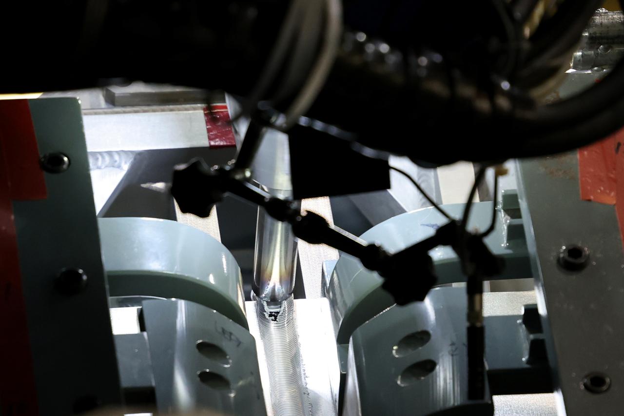
At NASA’s Michoud Assembly Facility in New Orleans, technicians from Orion prime contractor Lockheed Martin have welded together three cone-shaped panels on Orion’s crew module for the Artemis III mission that will land the first woman and next man on the Moon. The crew module’s primary structure, the pressure vessel, is comprised of seven machined aluminum alloy pieces that are welded together through a weld process that produces a strong, air-tight habitable space for astronauts during the mission. The pressure vessel is designed to withstand the harsh and demanding environment of deep space, and is the core structure upon which all the other elements of Orion’s crew module are integrated. Infographic showing the seven pieces of Orion's underlying structure With welding complete on the crew module cone panels – one of which contains windows providing astronauts views of the Moon and Earth – work will begin joining the forward bulkhead to the tunnel to create the top of the spacecraft, followed by the barrel and aft bulkhead join to form the bottom of Orion. Last, the forward bulkhead will be welded to the top of the panels and, for the seventh and closeout weld, the bottom of the cone panels will be joined to the barrel to complete the pressure vessel. Once welding of the Artemis III crew module primary structure is complete, it will be shipped to NASA’s Kennedy Space Center in Florida where it will undergo further assembly beginning this fall. Orion, the Space Launch System, and Exploration Ground Systems programs are foundational elements of the Artemis program. Artemis I will be the first integrated flight test of Orion and SLS and is targeted to launch later this year. Artemis II will follow and is the first crewed mission, taking humans farther into space than ever before. Image credit: NASA/Michael DeMocker
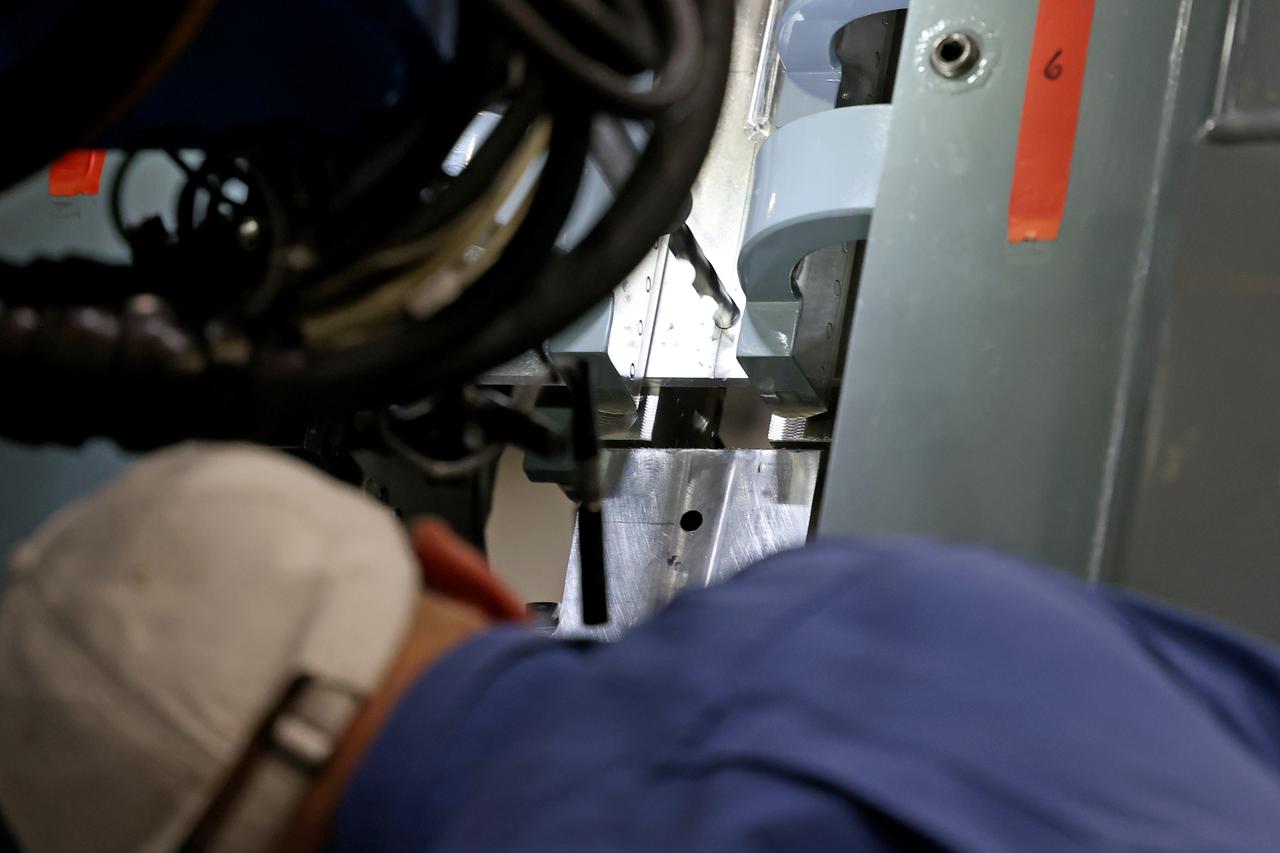
At NASA’s Michoud Assembly Facility in New Orleans, technicians from Orion prime contractor Lockheed Martin have welded together three cone-shaped panels on Orion’s crew module for the Artemis III mission that will land the first woman and next man on the Moon. The crew module’s primary structure, the pressure vessel, is comprised of seven machined aluminum alloy pieces that are welded together through a weld process that produces a strong, air-tight habitable space for astronauts during the mission. The pressure vessel is designed to withstand the harsh and demanding environment of deep space, and is the core structure upon which all the other elements of Orion’s crew module are integrated. Infographic showing the seven pieces of Orion's underlying structure With welding complete on the crew module cone panels – one of which contains windows providing astronauts views of the Moon and Earth – work will begin joining the forward bulkhead to the tunnel to create the top of the spacecraft, followed by the barrel and aft bulkhead join to form the bottom of Orion. Last, the forward bulkhead will be welded to the top of the panels and, for the seventh and closeout weld, the bottom of the cone panels will be joined to the barrel to complete the pressure vessel. Once welding of the Artemis III crew module primary structure is complete, it will be shipped to NASA’s Kennedy Space Center in Florida where it will undergo further assembly beginning this fall. Orion, the Space Launch System, and Exploration Ground Systems programs are foundational elements of the Artemis program. Artemis I will be the first integrated flight test of Orion and SLS and is targeted to launch later this year. Artemis II will follow and is the first crewed mission, taking humans farther into space than ever before. Image credit: NASA/Michael DeMocker
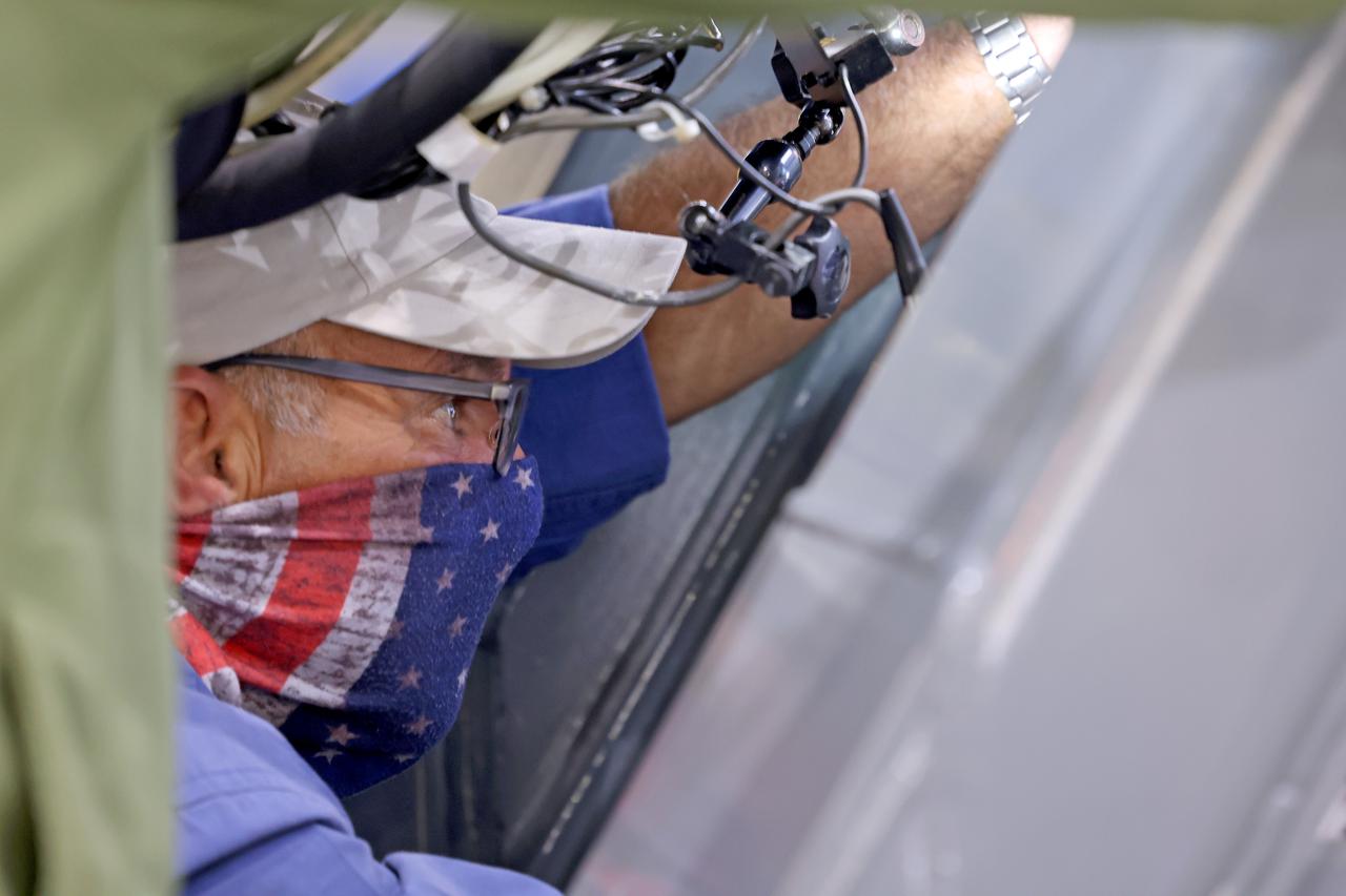
At NASA’s Michoud Assembly Facility in New Orleans, technicians from Orion prime contractor Lockheed Martin have welded together three cone-shaped panels on Orion’s crew module for the Artemis III mission that will land the first woman and next man on the Moon. The crew module’s primary structure, the pressure vessel, is comprised of seven machined aluminum alloy pieces that are welded together through a weld process that produces a strong, air-tight habitable space for astronauts during the mission. The pressure vessel is designed to withstand the harsh and demanding environment of deep space, and is the core structure upon which all the other elements of Orion’s crew module are integrated. Infographic showing the seven pieces of Orion's underlying structure With welding complete on the crew module cone panels – one of which contains windows providing astronauts views of the Moon and Earth – work will begin joining the forward bulkhead to the tunnel to create the top of the spacecraft, followed by the barrel and aft bulkhead join to form the bottom of Orion. Last, the forward bulkhead will be welded to the top of the panels and, for the seventh and closeout weld, the bottom of the cone panels will be joined to the barrel to complete the pressure vessel. Once welding of the Artemis III crew module primary structure is complete, it will be shipped to NASA’s Kennedy Space Center in Florida where it will undergo further assembly beginning this fall. Orion, the Space Launch System, and Exploration Ground Systems programs are foundational elements of the Artemis program. Artemis I will be the first integrated flight test of Orion and SLS and is targeted to launch later this year. Artemis II will follow and is the first crewed mission, taking humans farther into space than ever before. Image credit: NASA/Michael DeMocker
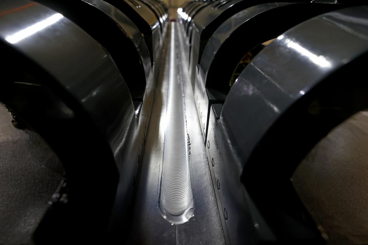
At NASA’s Michoud Assembly Facility in New Orleans, technicians from Orion prime contractor Lockheed Martin have welded together three cone-shaped panels on Orion’s crew module for the Artemis III mission that will land the first woman and next man on the Moon. The crew module’s primary structure, the pressure vessel, is comprised of seven machined aluminum alloy pieces that are welded together through a weld process that produces a strong, air-tight habitable space for astronauts during the mission. The pressure vessel is designed to withstand the harsh and demanding environment of deep space, and is the core structure upon which all the other elements of Orion’s crew module are integrated. Infographic showing the seven pieces of Orion's underlying structure With welding complete on the crew module cone panels – one of which contains windows providing astronauts views of the Moon and Earth – work will begin joining the forward bulkhead to the tunnel to create the top of the spacecraft, followed by the barrel and aft bulkhead join to form the bottom of Orion. Last, the forward bulkhead will be welded to the top of the panels and, for the seventh and closeout weld, the bottom of the cone panels will be joined to the barrel to complete the pressure vessel. Once welding of the Artemis III crew module primary structure is complete, it will be shipped to NASA’s Kennedy Space Center in Florida where it will undergo further assembly beginning this fall. Orion, the Space Launch System, and Exploration Ground Systems programs are foundational elements of the Artemis program. Artemis I will be the first integrated flight test of Orion and SLS and is targeted to launch later this year. Artemis II will follow and is the first crewed mission, taking humans farther into space than ever before. Image credit: NASA/Michael DeMocker