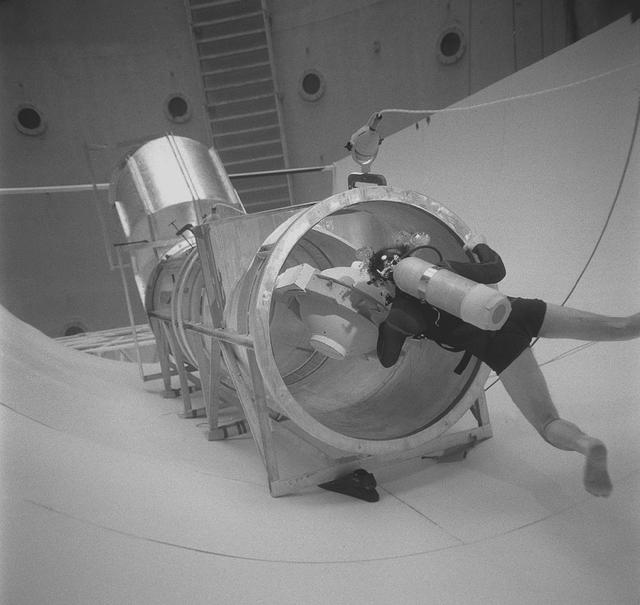
A Marshall scientist practices transferring objects in the Neutral Buoyancy Simulator (NBS) for the Spacelab transfer tunnel test.
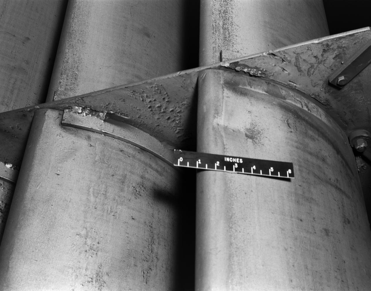
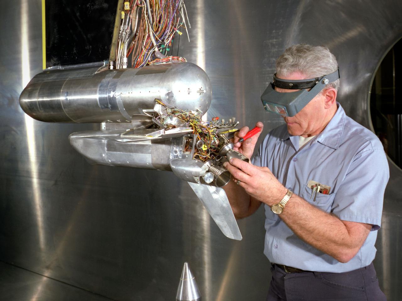
Prop Damage in the 8 foot TT (Transfer Tunnel)
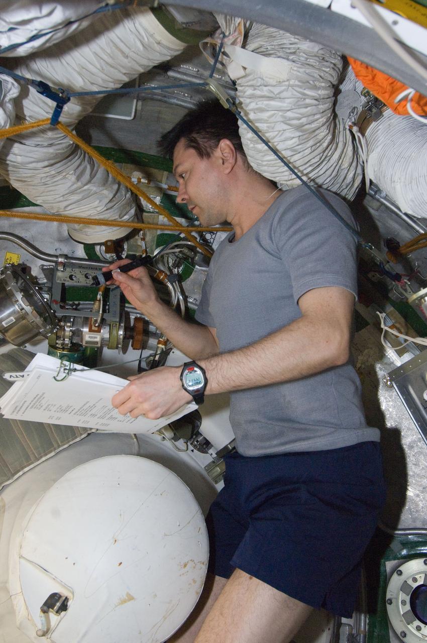
ISS030-E-177370 (29 March 2012) --- Russian cosmonaut Oleg Kononenko, Expedition 30 flight engineer, conducts a leak check in the Zvezda Service Module transfer tunnel/ATV vestibule of the International Space Station.
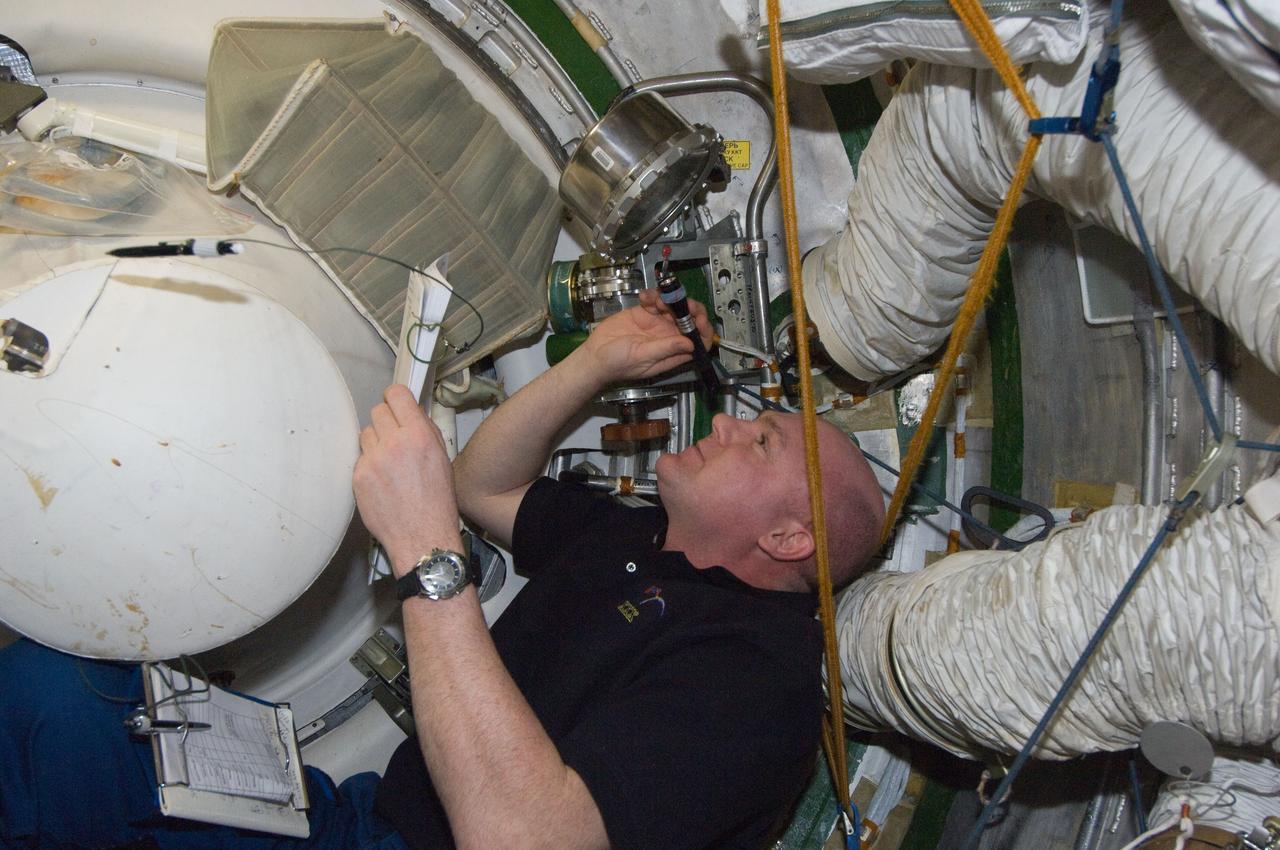
ISS030-E-177373 (29 March 2012) --- European Space Agency astronaut Andre Kuipers, Expedition 30 flight engineer, conducts a leak check in the Zvezda Service Module transfer tunnel/ATV vestibule of the International Space Station.
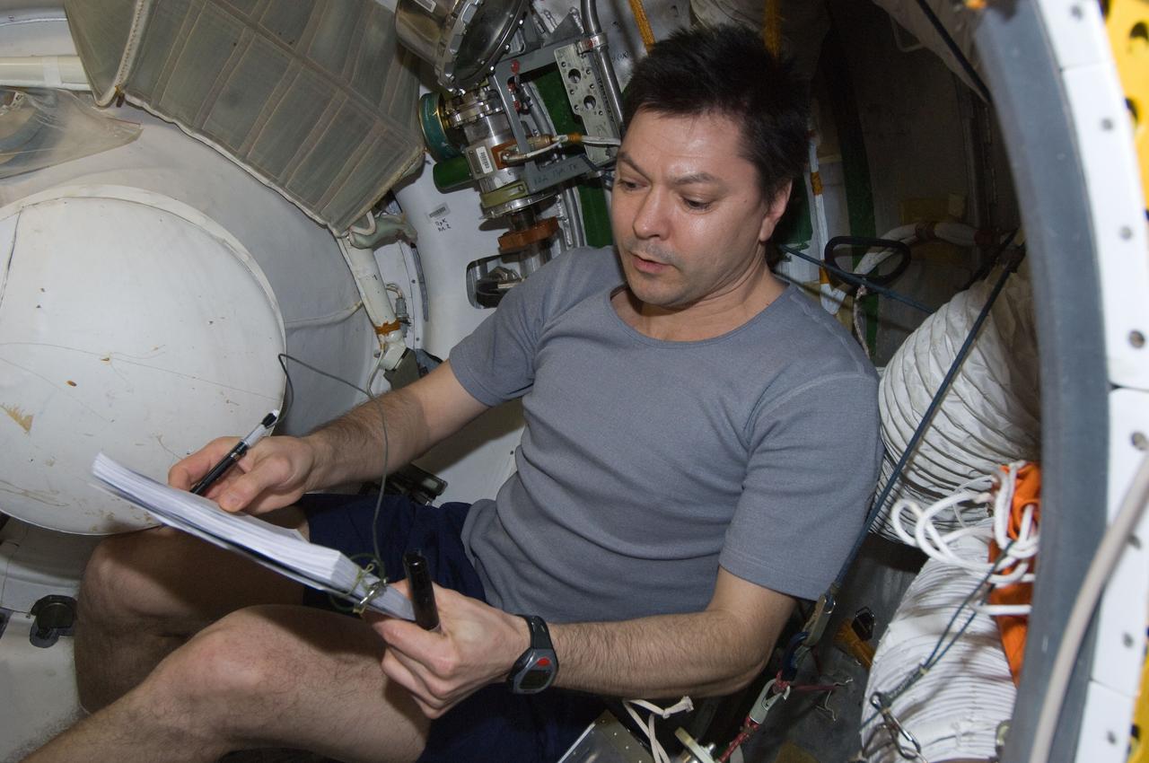
ISS030-E-177375 (29 March 2012) --- Russian cosmonaut Oleg Kononenko, Expedition 30 flight engineer, reviews a procedures checklist while conducting a leak check in the Zvezda Service Module transfer tunnel/ATV vestibule of the International Space Station.
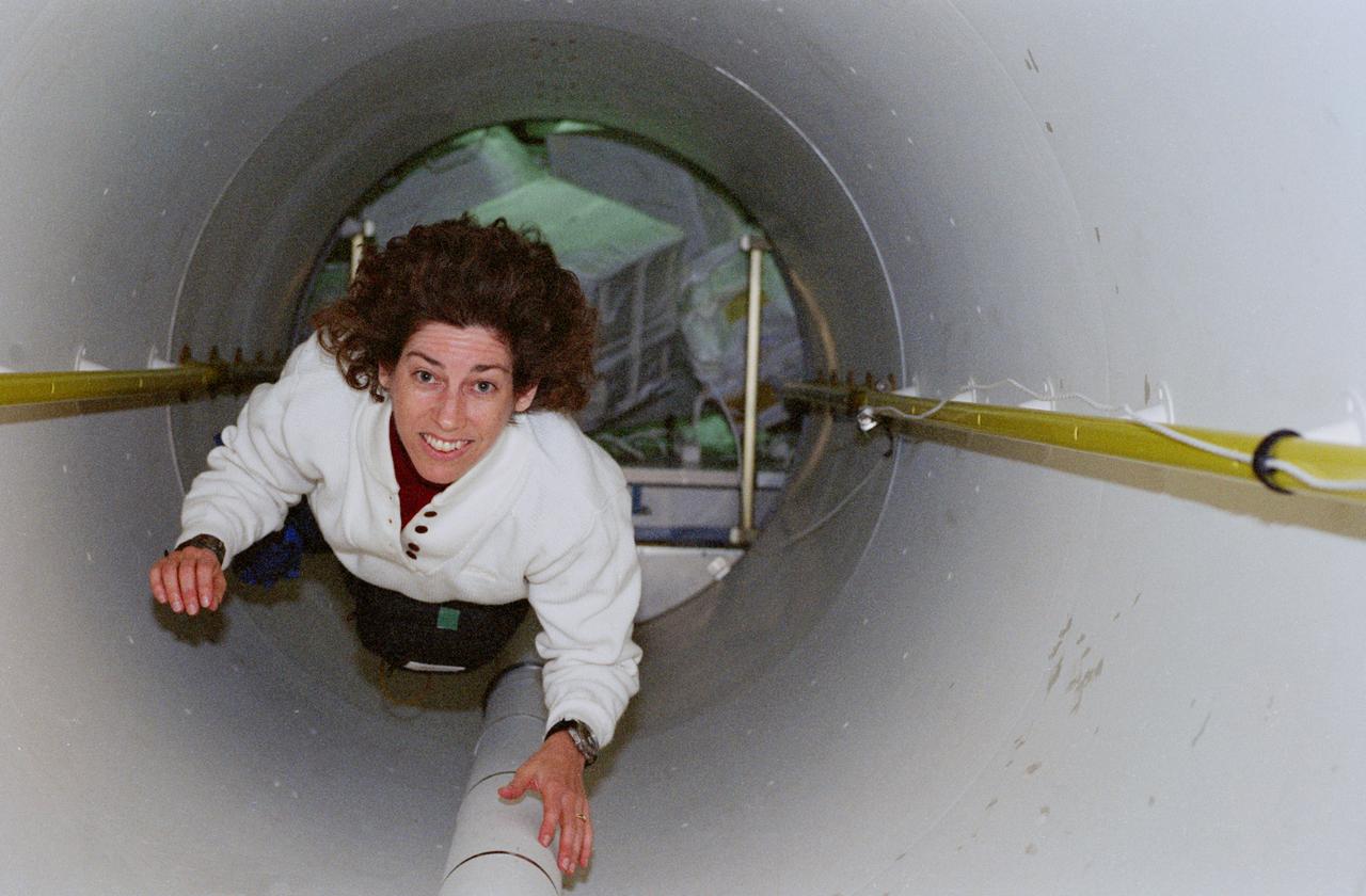
STS096-364-002 (27 May - 6 June 1999) --- Astronaut Ellen Ochoa floats through the tunnel that connected the STS-96 crew to the International Space Station (ISS) for several days in late May and early June 1999. The crew members eventually transferred several thousand pounds of supplies from Discovery to the ISS. Some of the gear can be seen behind Ochoa.
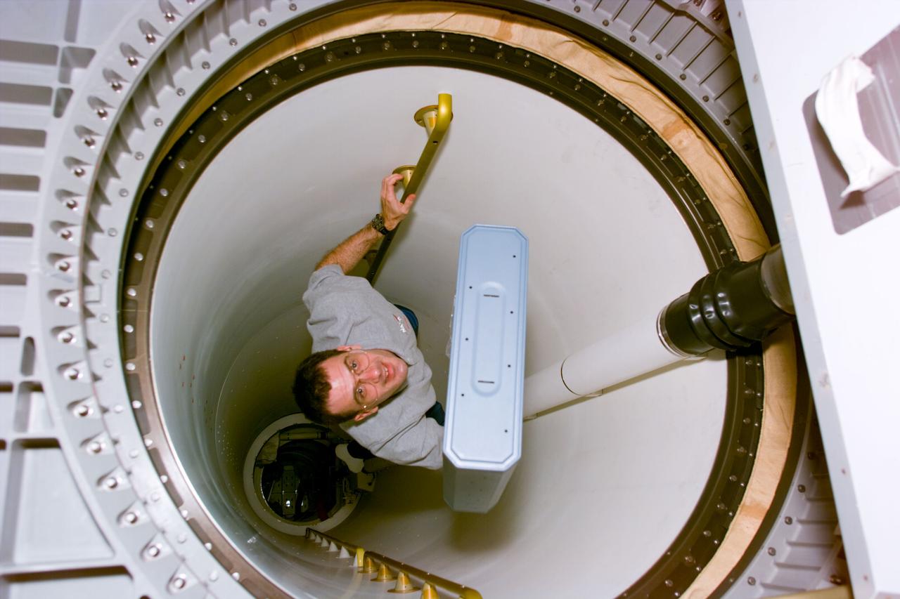
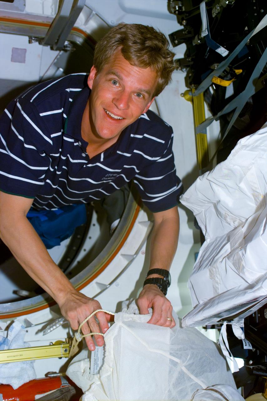
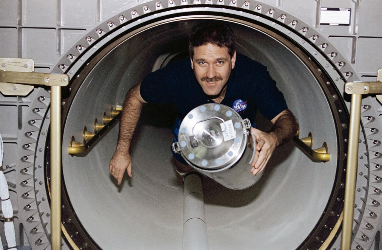
STS081-E-05100 (12 Jan. 1997) --- Astronaut Peter J. K. (Jeff) Wisoff, mission specialist, carries a stowage drawer from the middeck of the Space Shuttle Atlantis' crew cabin through a connective tunnel into the Spacehab Double Module (DM). In a few days, Wisoff and his five crew mates are scheduled to dock with Russia's Mir Space Station and pick up John E. Blaha, NASA astronaut who has been serving as a cosmonaut guest researcher since September, 1996. Astronaut Jerry M. Linenger will replace Blaha onboard Mir and the transfer will mark the second such direct exchange of cosmonaut guest researchers, though Linenger will be the fourth United States astronaut to spend a lengthy stay on Mir.
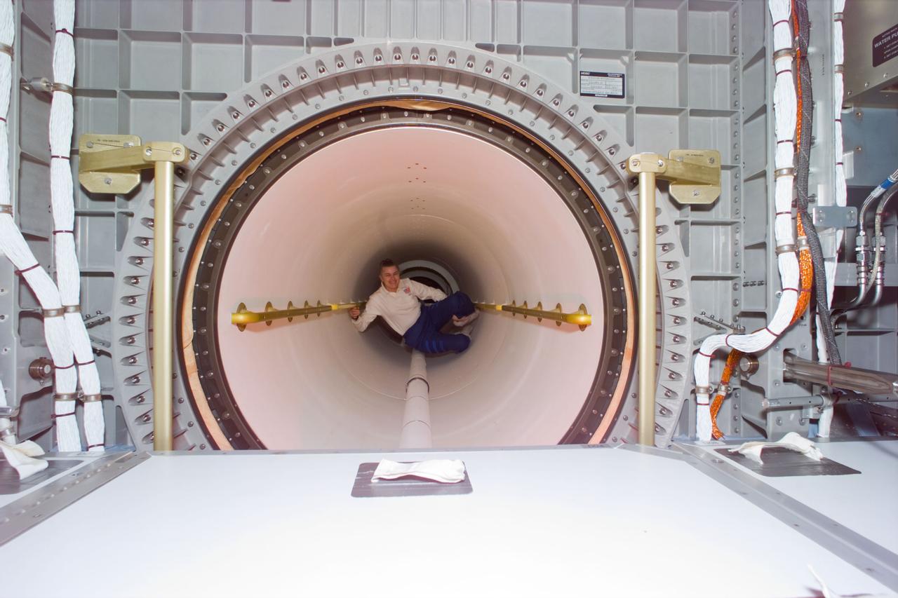
STS79-E-5371 (24 September 1996) --- Approaching the end of a stay in space exceeding six months, astronaut Shannon W. Lucid floats through the tunnel that connects Spacehab to the Space Shuttle Atlantis' cabin.
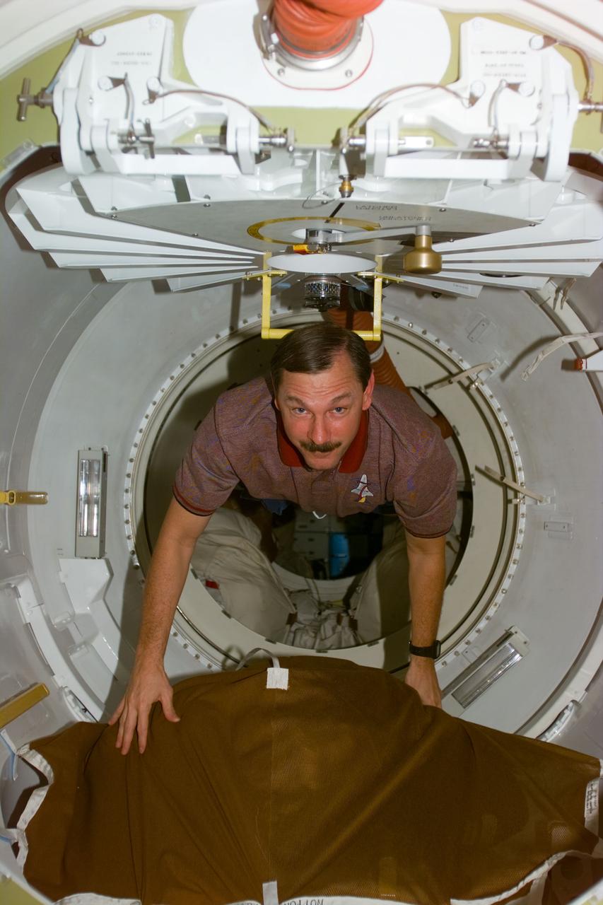
STS095-E-5052 (30 Oct. 1998) --- Astronaut Scott E. Parazynski, STS-95 mission specialist, emerges from the tunnel that connects SPACEHAB to Discovery's middeck during flight day two activity. The photo was taken with an electronic still camera (ESC) at 10:42:30, Oct. 30.
STS095-E-5160 (1 Nov. 1998) --- Astronaut Curtis L. Brown Jr., STS-95 commander, floats through airlock hatchway during Flight Day three activity. The photo was taken with an electronic still camera (ESC) at 01:39:20 GMT, Nov. 1.
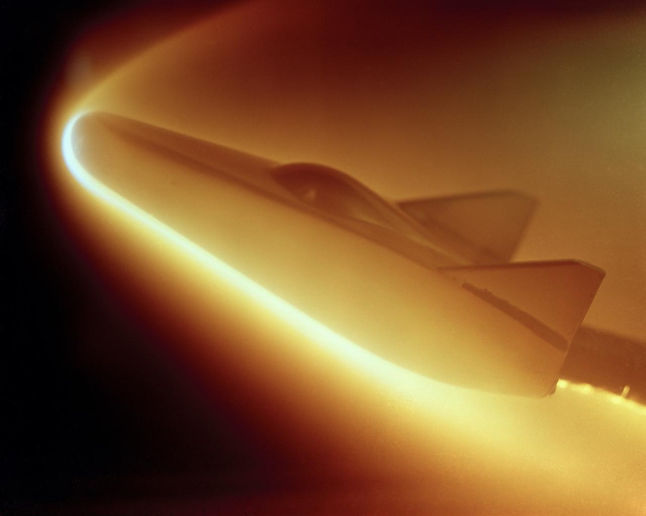
M-2 lifting body; heat transfer distribution test in the 1 ft hypervelocity wind tunnel
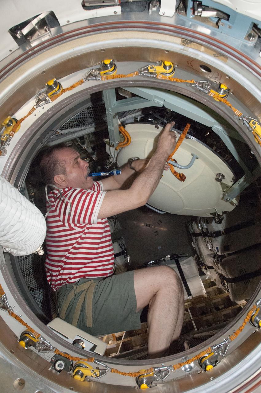
ISS036-E-009184 (18 June 2013) --- Russian cosmonaut Pavel Vinogradov, Expedition 36 commander, opens the hatch in the Zvezda Service Module transfer tunnel/ATV vestibule of the International Space Station after European Space Agency's Automated Transfer Vehicle-4 (ATV-4) "Albert Einstein" docked with the station.
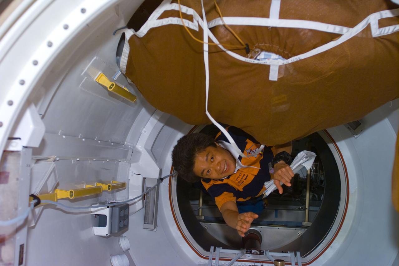
STS095-E-5214 (4 Nov. 1998) --- Payload specialist Chiaki Mukai floats into the airlock during Flight Day 6 activity aboard the Space Shuttle Discovery. A tunnel between Disovery's airlock and the cargo bay allows the payload specialist and her six STS-95 crewmates to access the Spacehab facility. The photo was taken with an electonic still camera (ESC) at 02:58:49 GMT, Nov. 4.
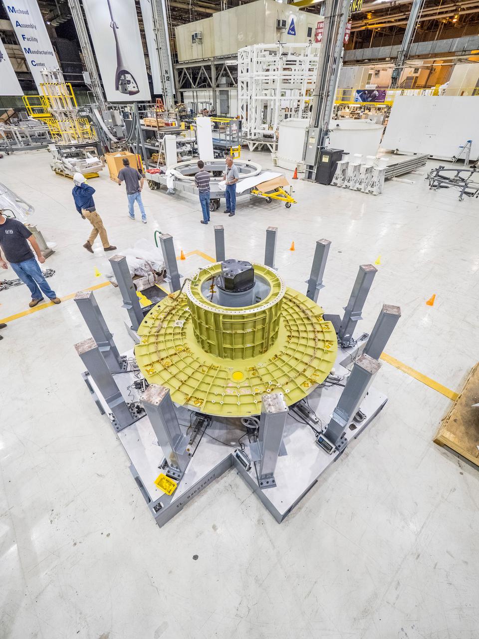
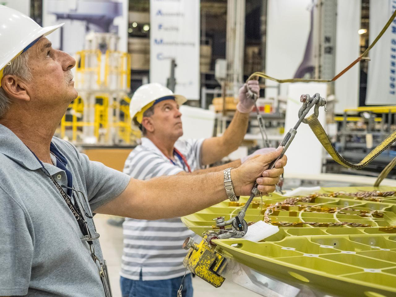
The first welded part of Artemis I Orion, the forward bulkhead and tunnel, is moved into final tooling at the Michoud Assembly Facility in New Orleans, Louisiana on Oct. 12, 2015. Part of Batch image transfer from Flickr.
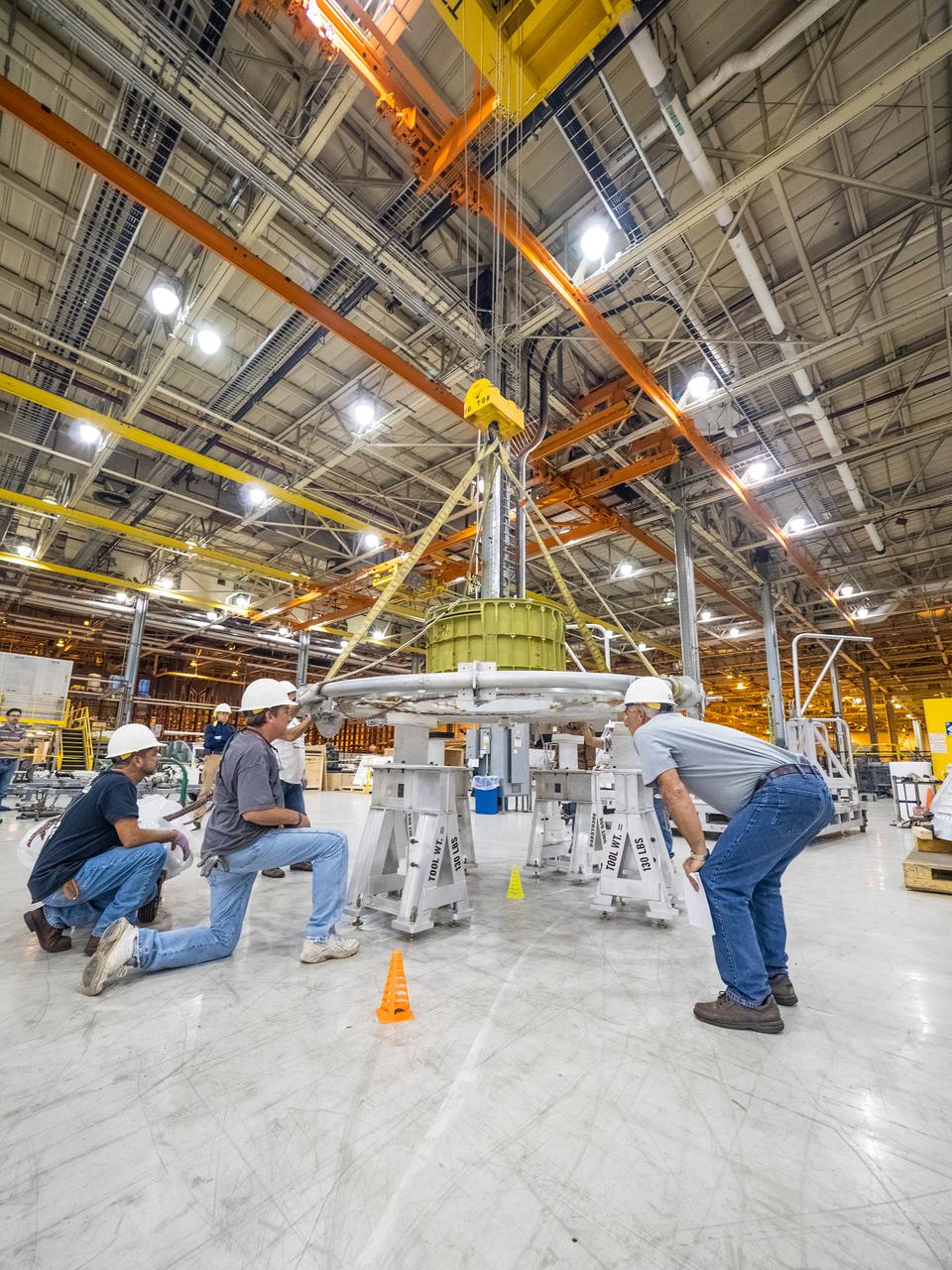
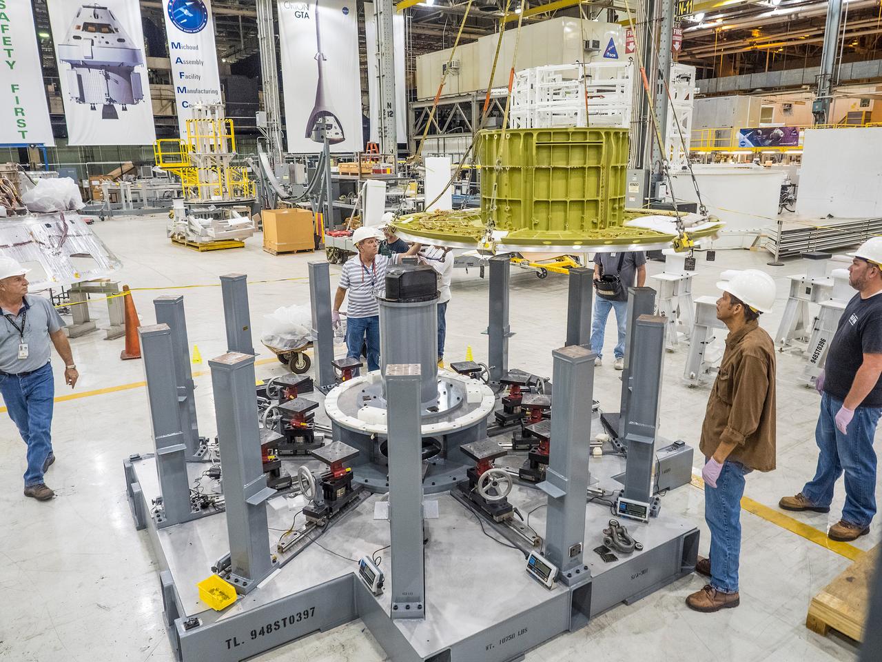
The first welded part of Artemis I Orion, the forward bulkhead and tunnel, is moved into final tooling at the Michoud Assembly Facility in New Orleans, Louisiana on Oct. 12, 2015. Part of Batch image transfer from Flickr.
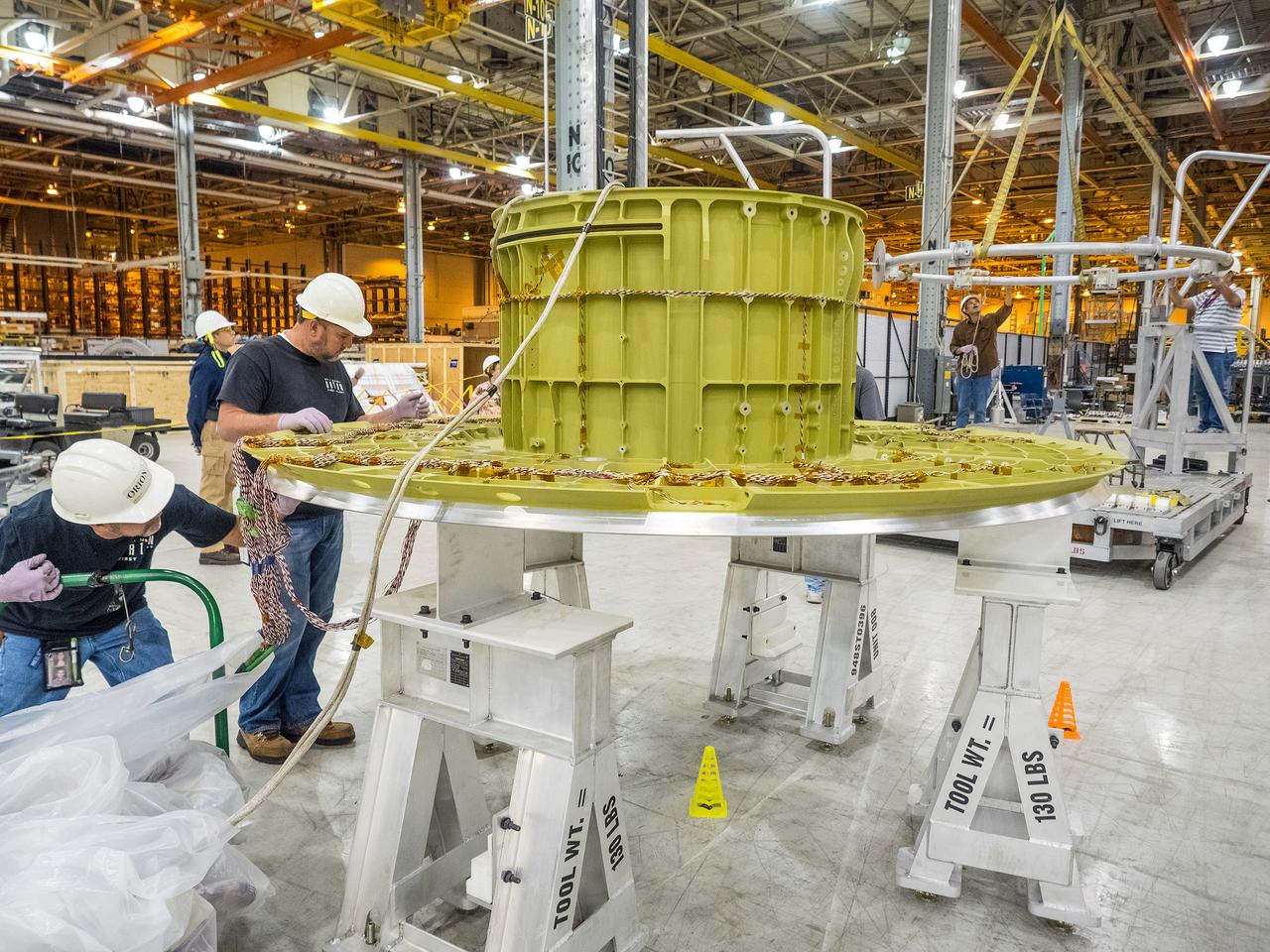
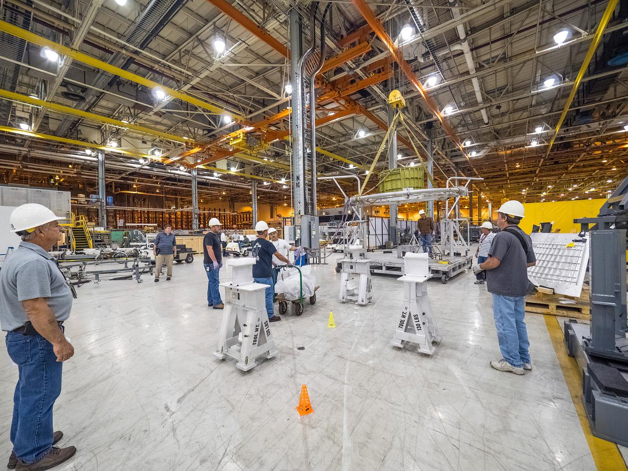
The first welded part of Artemis I Orion, the forward bulkhead and tunnel, is moved into final tooling at the Michoud Assembly Facility in New Orleans, Louisiana on Oct. 12, 2015. Part of Batch image transfer from Flickr.
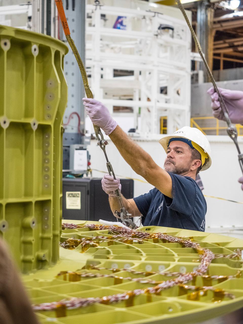
The first welded part of Artemis I Orion, the forward bulkhead and tunnel, is moved into final tooling at the Michoud Assembly Facility in New Orleans, Louisiana on Oct. 12, 2015. Part of Batch image transfer from Flickr.
The first welded part of Artemis I Orion, the forward bulkhead and tunnel, is moved into final tooling at the Michoud Assembly Facility in New Orleans, Louisiana on Oct. 12, 2015. Part of Batch image transfer from Flickr.
The first welded part of Artemis I Orion, the forward bulkhead and tunnel, is moved into final tooling at the Michoud Assembly Facility in New Orleans, Louisiana on Oct. 12, 2015. Part of Batch image transfer from Flickr.
The first welded part of Artemis I Orion, the forward bulkhead and tunnel, is moved into final tooling at the Michoud Assembly Facility in New Orleans, Louisiana on Oct. 12, 2015. Part of Batch image transfer from Flickr.
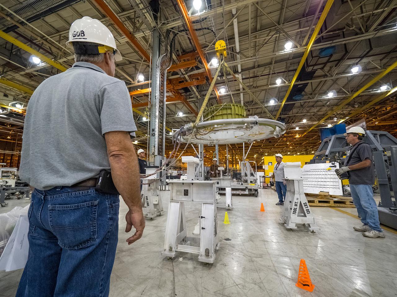
The first welded part of Artemis I Orion, the forward bulkhead and tunnel, is moved into final tooling at the Michoud Assembly Facility in New Orleans, Louisiana on Oct. 12, 2015. Part of Batch image transfer from Flickr.
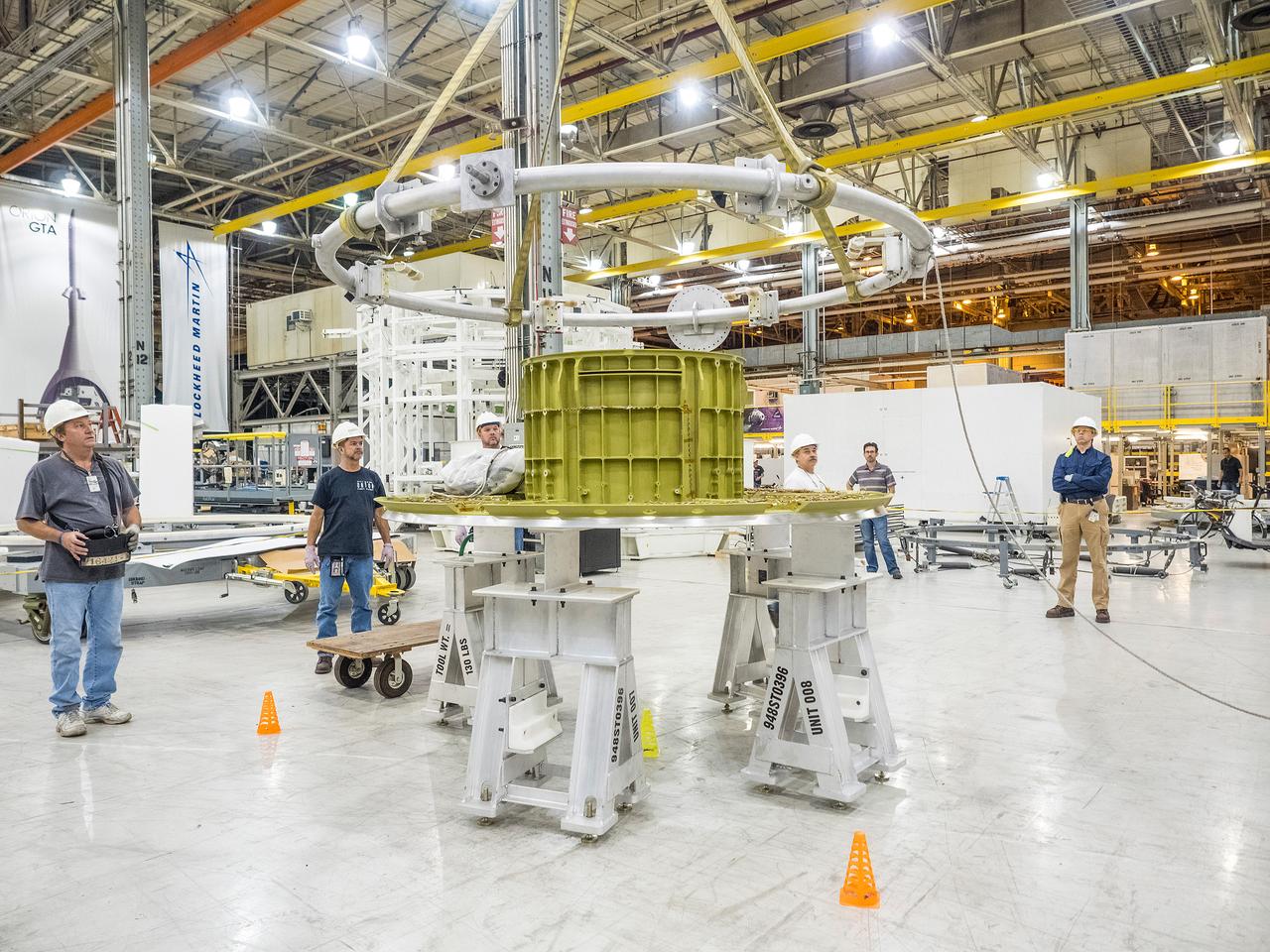
The first welded part of Artemis I Orion, the forward bulkhead and tunnel, is moved into final tooling at the Michoud Assembly Facility in New Orleans, Louisiana on Oct. 12, 2015. Part of Batch image transfer from Flickr.
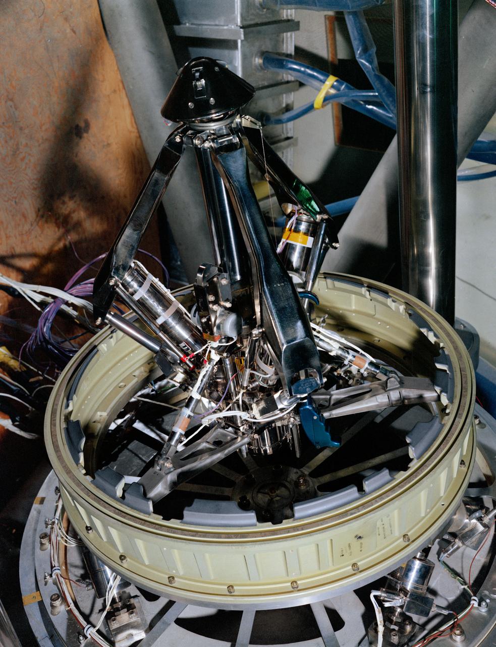
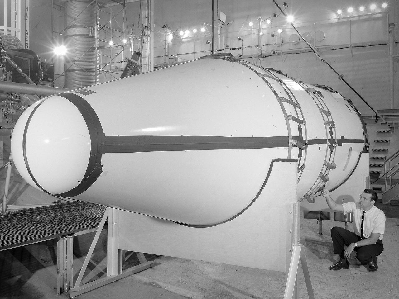
S68-50870 (1968) --- An engineering set up illustrating the probe portion of the docking system of the Apollo spacecraft. During docking maneuvers the docking probe on the Command Module (CM) engages the cone shaped drogue of the Lunar Module (LM). The primary docking structure is the tunnel through which the astronauts transfer from one module to the other. This tunnel is partly in the nose of the CM and partly in the top of the LM. Following CSM/LM docking the drogue and probe are removed to open the passageway between the modules.
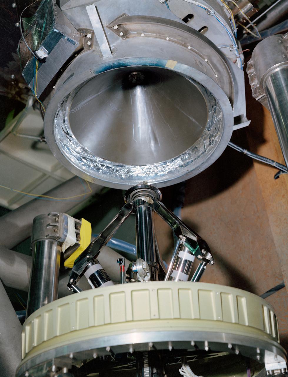
S68-50869 (1968) --- An engineering set up illustrating the docking system of the Apollo spacecraft. During docking maneuvers the docking probe on the Command Module engages the cone-shaped drogue of the Lunar Module. The primary docking structure is the tunnel through which the astronauts transfer from one module to the other. This tunnel is partly in the nose of the Command Module and partly in the top of the Lunar Module. Following CSM/LM docking the drogue and probe are removed to open the passageway between the modules.
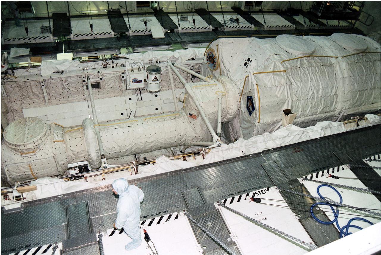
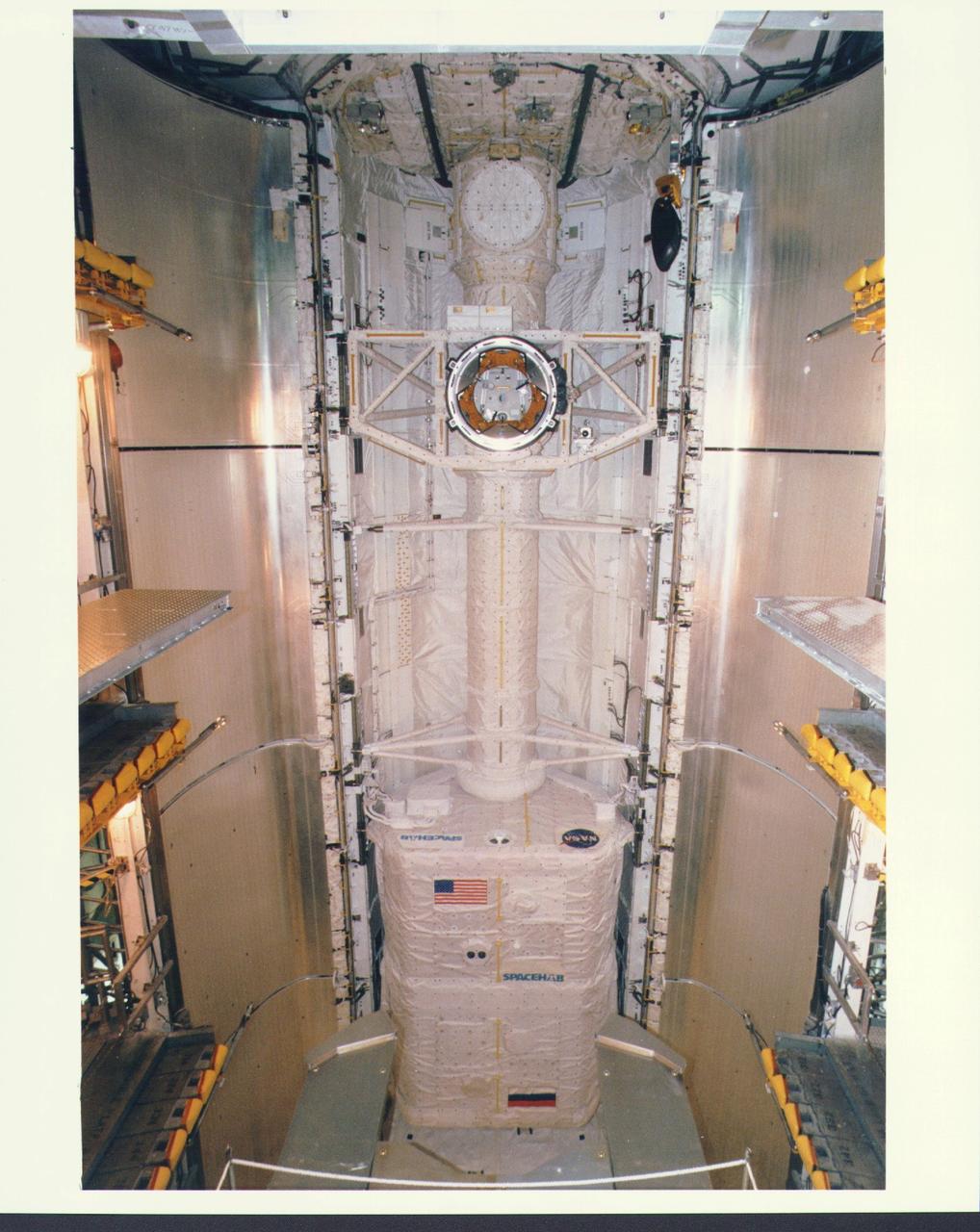
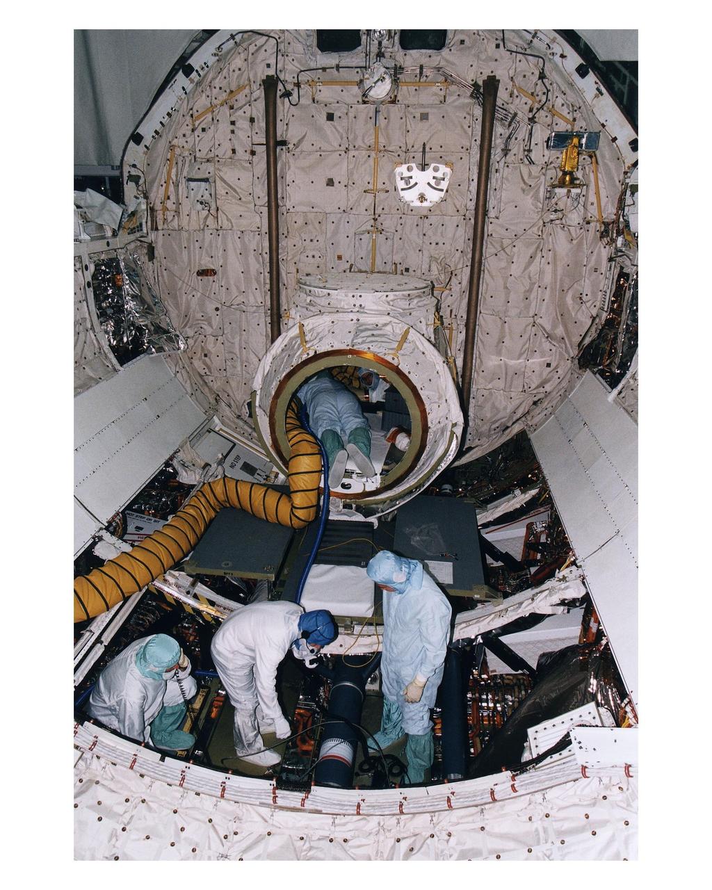
KENNEDY SPACE CENTER, FLA. - The Microgravity Science Laboratory-1 (MSL-1) Spacelab module is installed into the payload bay of the Space Shuttle Orbiter Columbia in Orbiter Processing Facility 1. The Spacelab long crew transfer tunnel that leads from the orbiter's crew airlock to the module is also aboard, as well as the Hitchhiker Cryogenic Flexible Diode (CRYOFD) experiment payload, which is attached to the right side of Columbia's payload bay. During the scheduled 16-day STS-83 mission, the MSL-1 will be used to test some of the hardware, facilities and procedures that are planned for use on the International Space Station while the flight crew conducts combustion, protein crystal growth and materials processing experiments.
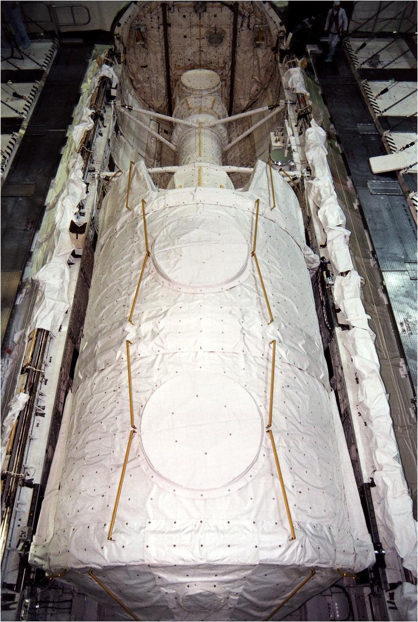
KENNEDY SPACE CENTER, FLA. - The Microgravity Science Laboratory-1 (MSL-1) Spacelab module is installed into the payload bay of the Space Shuttle Orbiter Columbia in Orbiter Processing Facility 1. The Spacelab long crew transfer tunnel that leads from the orbiter's crew airlock to the module is also aboard, as well as the Hitchhiker Cryogenic Flexible Diode (CRYOFD) experiment payload, which is attached to the right side of Columbia's payload bay. During the scheduled 16-day STS-83 mission, the MSL-1 will be used to test some of the hardware, facilities and procedures that are planned for use on the International Space Station while the flight crew conducts combustion, protein crystal growth and materials processing experiments.
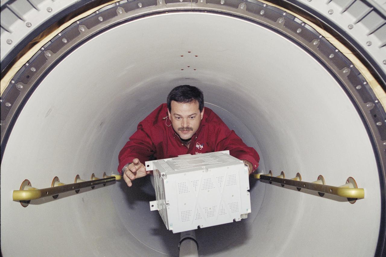
STS081-361-026 (12-22 Jan 1997) --- Astronaut John M. Grunsfeld, mission specialist, floats into the Spacehab Double Module (DM) bearing a freezer unit in support of experimentation, onboard the Space Shuttle Atlantis during the Atlantis - Russia?s Mir Space Station docking mission.
STS106-301-018 (8-20 September 2000) --- Astronaut Scott D. Altman, pilot, translates through the tunnel to the International Space Station (ISS) with a new battery in hand. The seven-man STS-106 crew was in the process of a major moving effort of supplies and hardware from the Space Shuttle Atlantis to the station.
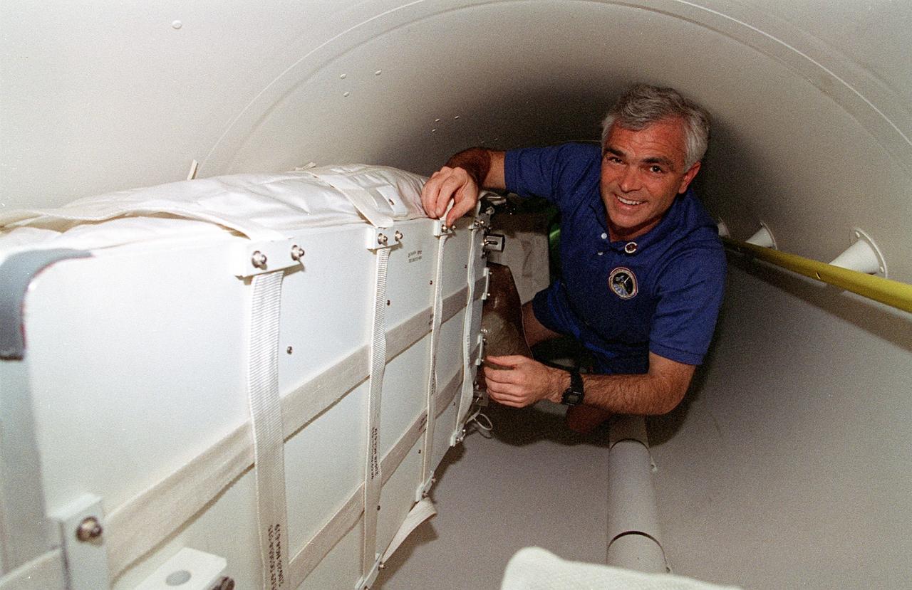
STS076-345-014 (22-31 March 1996) --- During the first few hours of the mission, astronaut Michael R. (Rich) Clifford checks over stowed bags filled Extravehicular Activity (EVA) supplies in the STS-76 tunnel. The mission specialist, one of six NASA astronauts aboard the Space Shuttle Atlantis, later helped move the bags to Atlantis' airlock. Atlantis later docked with Russia's Mir Space Station. The crew used a tunnel to commute to the Spacehab module and, later, to the Mir via its Docking Module (DM).
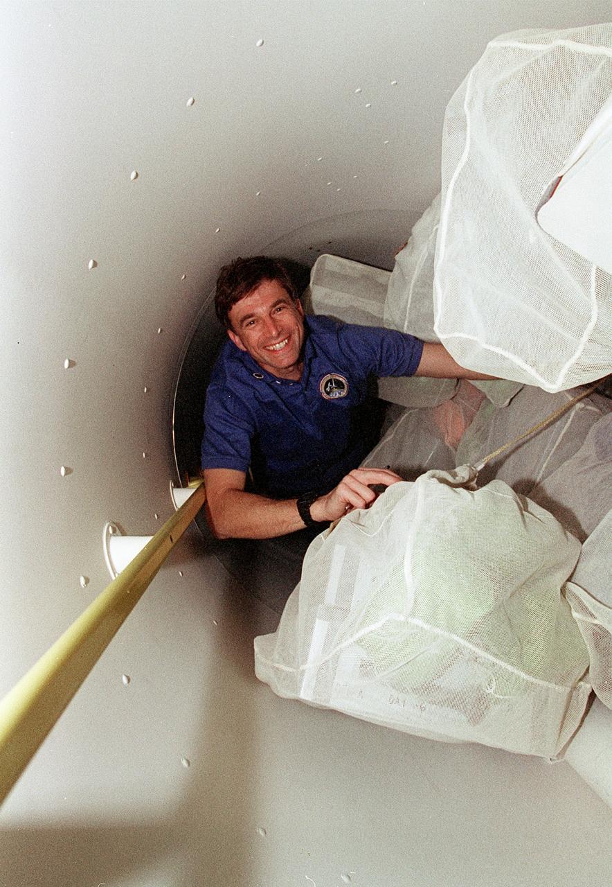
STS076-345-012 (22 - 31 March 1996) --- During the first few hours of the mission, astronaut Ronald M. Sega checks over stowed bags filled with food supplies in the STS-76 tunnel. The payload commander was one of six NASA astronauts aboard the Space Shuttle Atlantis, which later docked with Russia's Mir Space Station. The crew used a tunnel to commute to the Spacehab module and, later, to the Mir via its Docking Module (DM).
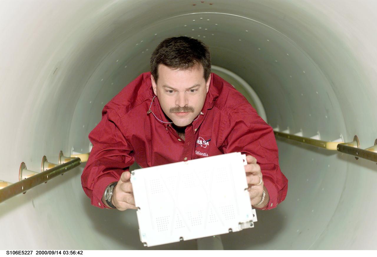
S106-E-5227 (14 September 2000) --- Astronaut Scott D. Altman, pilot, carries supplies through the tunnel leading from Spacehab to the International Space Station (ISS).
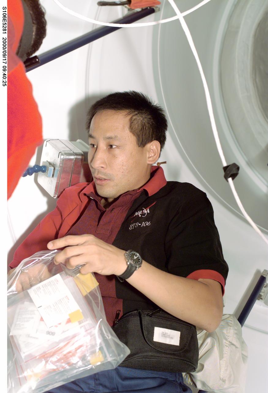
S106-E-5281 (17 September 2000) --- Astronaut Edward T. Lu, mission specialist, can literally see the light at the end of the tunnel, as he and six STS-106 crewmates wind down toward the end of their interface with the International Space Station (ISS). The crew soon will be sealing itself off from the station and returning to the crew cabin of Atlantis and Spacehab for the remainder of the 12-day mission.
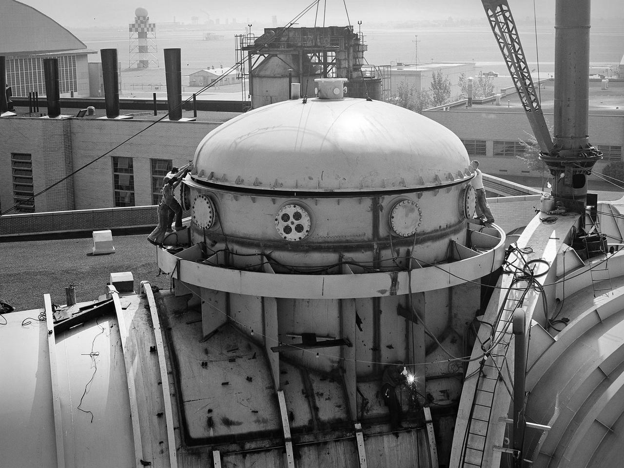
This 22.5-foot-diameter domed lid was added to the Space Power Chambers to allow the vertical installation of a Centaur second-stage rocket into the vacuum tank at the National Aeronautics and Space Administration (NASA) Lewis Research Center. The lid could be removed using a crane so that the Centaur could be lowered into the chamber. After a year of additional construction, the new dome and extension were completed in September 1963. The feature became the facility’s distinctive attribute. The modifications to the facility began two years earlier, however. In 1961, NASA Lewis management decided to convert the Altitude Wind Tunnel into two large test chambers and later renamed it the Space Power Chambers. The conversion included the removal of the tunnel’s internal components and the insertion of bulkheads to seal off the new chambers within the tunnel. The 100-foot-long vacuum tank was created in the east leg of the tunnel, which was 31 feet in diameter at one end and 27 feet in diameter at the other. With the transfer of the Centaur second-stage rocket program to NASA Lewis in October 1962, the newly completed Space Power Chambers facility had to be modified to accommodate the space vehicle. The goal of the test engineers was to subject the Centaur to long durations in conditions that would replicate those encountered during its missions in space. The facility was used for a variety of tests on the Centaur second-stage rocket until the early 1970s.

These compressors inside the Refrigeration Building at the National Advisory Committee for Aeronautics (NACA) Aircraft Engine Research Laboratory were used to generate cold temperatures in the Altitude Wind Tunnel (AWT) and Icing Research Tunnel. The AWT was a large facility that simulated actual flight conditions at high altitudes. The two primary aspects of altitude simulation are the reduction of the air pressure and the decrease of temperature. The Icing Research Tunnel was a smaller facility in which water droplets were added to the refrigerated air stream to simulate weather conditions that produced ice buildup on aircraft. The military pressured the NACA to complete the tunnels quickly so they could be of use during World War II. The NACA engineers struggled with the design of this refrigeration system, so Willis Carrier, whose Carrier Corporation had pioneered modern refrigeration, took on the project. The Carrier engineers devised the largest cooling system of its kind in the world. The system could lower the tunnels’ air temperature to –47⁰ F. The cooling system was powered by 14 Carrier and York compressors, seen in this photograph, which were housed in the Refrigeration Building between the two wind tunnels. The compressors converted the Freon 12 refrigerant into a liquid. The refrigerant was then pumped into zig-zag banks of cooling coils inside the tunnels’ return leg. The Freon absorbed heat from the airflow as it passed through the coils. The heat was transferred to the cooling water and sent to the cooling tower where it was dissipated into the atmosphere.
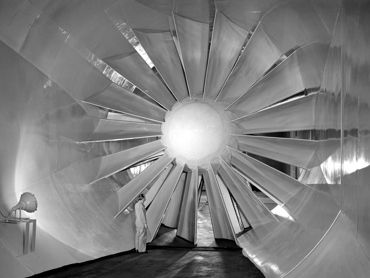
A researcher examines the drive fan inside the Icing Research Tunnel at the National Advisory Committee for Aeronautics (NACA) Flight Propulsion Research Laboratory in Cleveland, Ohio. The facility was built in the mid-1940s to simulate the atmospheric conditions that caused ice to build up on aircraft. Carrier Corporation refrigeration equipment reduced the internal air temperature to -45⁰ F, and a spray bar system injected water droplets into the air stream. The 24-foot diameter drive fan, seen in this photograph, created air flow velocities up to 400 miles per hour. The 1950s were prime years for the Icing Research Tunnel. NACA engineers had spent the 1940s trying to resolve the complexities of the spray bar system. The final system put into operation in 1950 included six horizontal spray bars with 80 nozzles that produced a 4- by 4-foot cloud in the test section. The icing tunnel was used for extensive testing of civilian and military aircraft components in the 1950s. The NACA also launched a major investigation of the various methods of heating leading edge surfaces. The hot-air anti-icing technology used on today’s commercial transports was largely developed in the facility during this period. Lewis researchers also made significant breakthroughs with icing on radomes and jet engines. Although the Icing Research Tunnel yielded major breakthroughs in the 1950s, the Lewis icing research program began tapering off as interest in the space program grew. The icing tunnel’s use declined in 1956 and 1957. The launch of Sputnik in October 1957 signaled the end of the facility’s operation. The icing staff was transferred to other research projects and the icing tunnel was temporarily mothballed.

S-65 Meteor Impact Model set up in the former Altitude Wind Tunnel at the National Aeronautics and Space Administration (NASA) Lewis Research Center just days after the September 12, 1962 rededication of the facility as the Space Power Chamber. Although larger test chambers would later be constructed, the rapid conversion of the wind tunnel into two space tanks allowed the facility to play a vital role in the early years of the space program. The eastern section of the tunnel, seen here became a vacuum chamber capable of simulating 100 miles altitude. This space tank was envisioned for the study of small satellites like this one. The transfer of the Centaur Program to Lewis one month late, however, permanently changed this mission. NASA was undertaking an in depth study at the time on the effect of micrometeoroids on satellites. Large space radiators were particularly vulnerable to damage from the small particles of space debris. In order to determine the hazard from meteoroids researchers had to define the flux rate relative to the mass and the velocity distribution because the greater the mass or the velocity of a meteoroid the greater the damage.
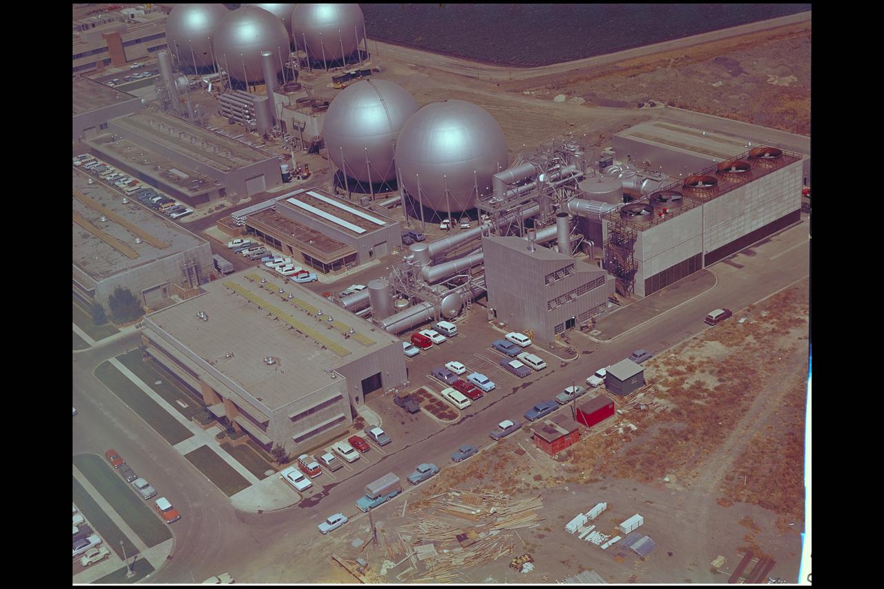
Aerial view of Gasdynamics facility in 1964 and the 20 inch helium tunnel Part of the Thermal Protection Laboratory used to research materials for heat shield applications and for aerodynamic heating and materials studies of vehicles in planetary atmospheres. This laboratory is comprised of five separate facilities: an Aerodynamic Heating Tunnel, a Heat Transfer Tunnel, two Supersonic Turbulent Ducts, and a High-Power CO2 Gasdynamic Laser. All these facilities are driven by arc-heaters, with the exception of the large, combustion-type laser. The arc-heated facilities are powered by a 20 Megawatt DC power supply. Their effluent gas stream (test gases; Air, N2, He, CO2 and mixtures; flow rates from 0.05 to 5.0 lbs/sec) discharges into a five-stage stream-ejector-driven vacuum system. The vacuum system and power supply are common to the test faciities in building N-238. All of the facilities have high pressure water available at flow rates up to 4, 000 gals/min. The data obtained from these facilities are recorded on magnetic tape or oscillographs. All forms of data can be handled whether from thermo-couples, pressure cells, pyrometers, or radiometers, etc. in addition, closed circuit T. V. monitors and various film cameras are available. (operational since 1962)
KENNEDY SPACE CENTER, FLA. - Workers in the Payload Changeout Room (PCR) at Launch Pad 39A are preparing to close the payload doors for flight on the Space Shuttle Atlantis, targeted for liftoff on Mission STS-79 around Sept. 12. The payloads in Atlantis' cargo bay will play key roles during the upcoming spaceflight, which will be highlighted by the fourth docking between the U.S. Shuttle and Russian Space Station Mir. Located in the aft (lowermost) area of the payload bay is the SPACEHAB Double Module, filled with supplies and other items slated for transfer to the Russian Space Station Mir as well as research equipment. The SPACEHAB is connected by tunnel to the Orbiter Docking System (ODS). This view looks directly at the top of the ODS and shows clearly the Androgynous Peripheral Docking System (APDS) that interfaces with the Docking Module on Mir to achieve a linkup.
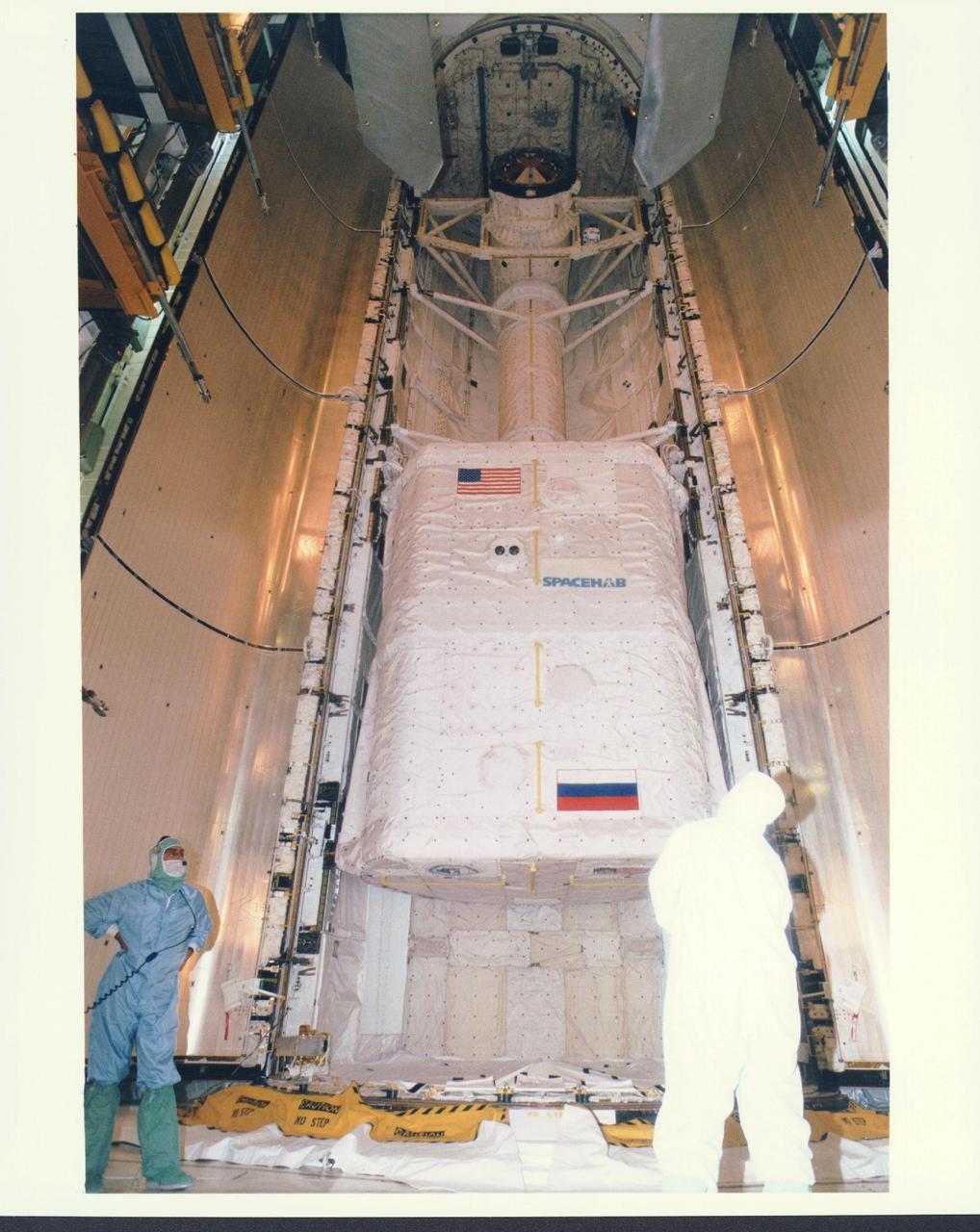
KENNEDY SPACE CENTER, FLA. - Workers in the Payload Changeout Room (PCR) at Launch Pad 39A are preparing to close the payload doors for flight on the Space Shuttle Atlantis, targeted for liftoff on Mission STS-79 around Sept. 12. The SPACEHAB Double Module located in the aft area of the payload bay is filled with supplies and other items slated for transfer to the Russian Space Station Mir. STS-79 marks the second flight of a SPACEHAB in support of the Shuttle-Mir dockings, and the first flight of the double-module configuration. The SPACEHAB is connected by tunnel to the Orbiter Docking System (ODS), with the Androgynous Peripheral Docking System (APDS) clearly visible on top of the ODS. The APDS provides the docking interface for the linkup with Mir, while the ODS provides a passageway from the orbiter to the Russian space station and the SPACEHAB.
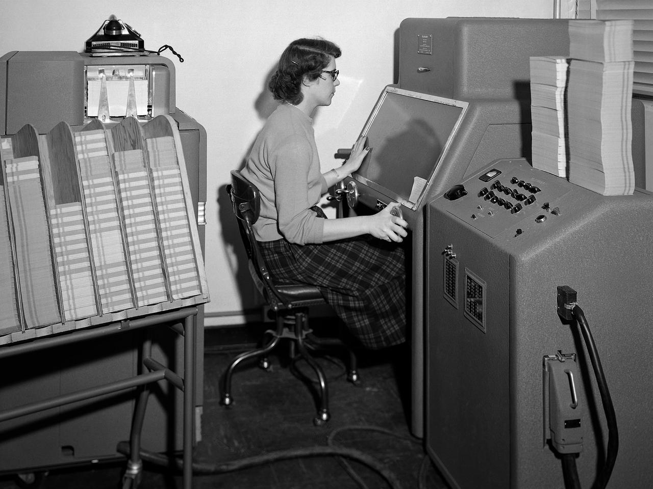
A staff member from the Computing Section at the National Advisory Committee for Aeronautics (NACA) Lewis Flight Propulsion Laboratory operates an International Business Machines (IBM) telereader at the 8- by 6-Foot Supersonic Wind Tunnel. The telereader was used to measure recorded data from motion picture film or oscillographs. The machine could perform 50 measurements per minute. The component to her right is a telerecordex that was used convert the telereader measurements into decimal form and record the data on computer punch cards. During test runs in the 8- by 6-foot tunnel, or the other large test facilities, pressure sensors on the test article were connected to mercury-filled manometer tubes located below the test section. The mercury would rise or fall in relation to the pressure fluctuations in the test section. Initially, female staff members, known as “computers,” transcribed all the measurements by hand. The process became automated with the introduction of the telereader and other data reduction equipment in the early 1950s. The Computer Section staff members were still needed to operate the machines. The Computing Section was introduced during World War II to relieve short-handed research engineers of some of the tedious work. The computers made the initial computations and plotted the data graphically. The researcher then analyzed the data and either summarized the findings in a report or made modifications or ran the test again. The computers and analysts were located in the Altitude Wind Tunnel Shop and Office Building office wing during the 1940s. They were transferred to the new facility when the 8- by 6-Foot tunnel began operations in 1948.
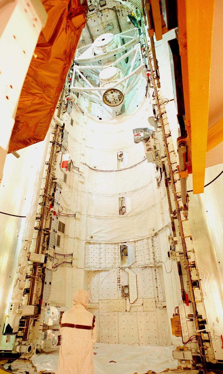
The open doors of the payload bay on Space Shuttle Discovery await the transfer of four of the payloads on mission STS-95: the SPACEHAB single module, Spartan, the Hubble Space Telescope Orbiting Systems Test Platform (HOST), and the International Extreme Ultraviolet Hitchhiker (IEH-3). At the top of bay are the airlock (used for depressurization and repressurization during extravehicular activity and transfer to Mir) and the tunnel adapter (enables the flight crew members to transfer from the pressurized middeck crew compartment to Spacelab's pressurized shirt-sleeve environment). SPACEHAB involves experiments on space flight and the aging process. Spartan is a solar physics spacecraft designed to perform remote sensing of the hot outer layers of the sun's atmosphere or corona. HOST carries four experiments to validate components planned for installation during the third Hubble Space Telescope servicing mission and to evaluate new technologies in an Earth-orbiting environment. IEH-3 comprises several experiments that will study the Jovian planetary system, hot stars, planetary and reflection nebulae, other stellar objects and their environments through remote observation of EUV/FUV emissions; study spacecraft interactions, Shuttle glow, thruster firings, and contamination; and measure the solar constant and identify variations in the value during a solar cycle. Discovery is scheduled to launch on Oct. 29, 1998
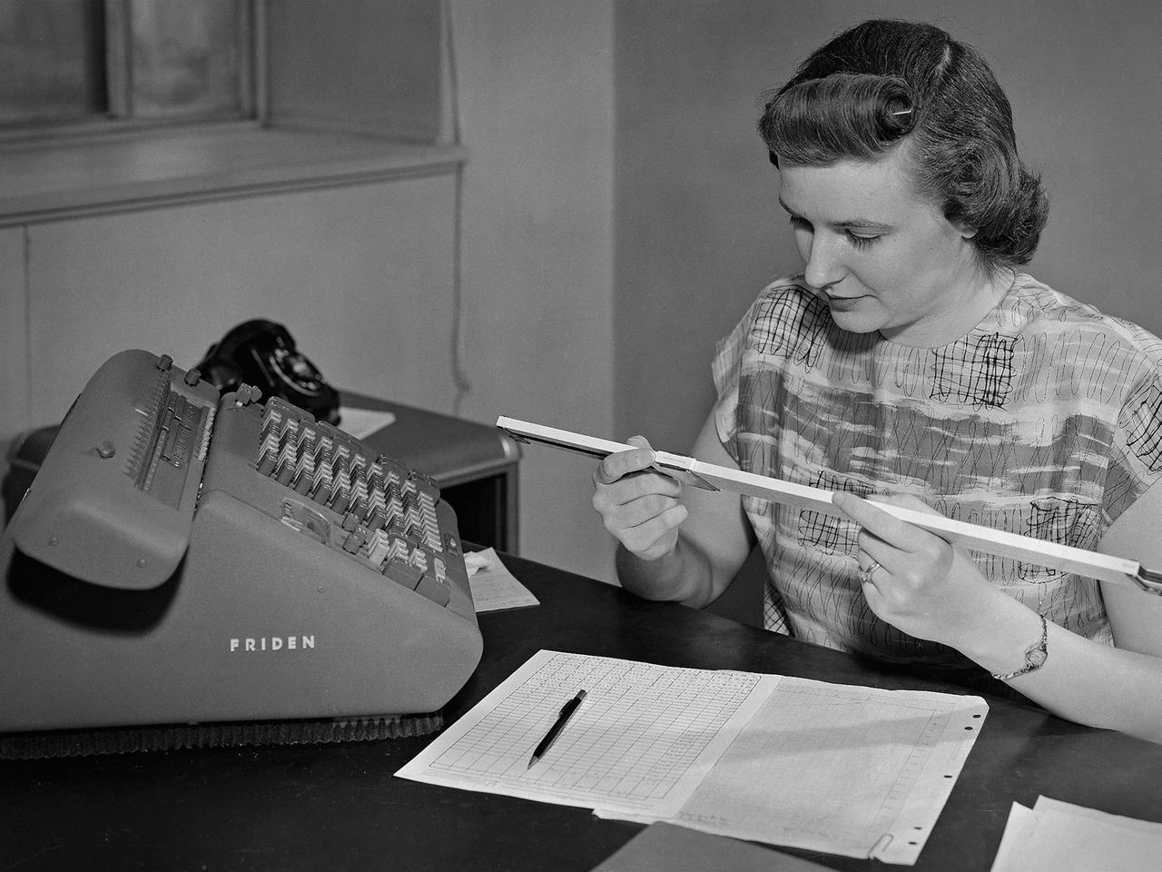
A female computer at the National Advisory Committee for Aeronautics (NACA) Lewis Flight Propulsion Laboratory with a slide rule and Friden adding machine to make computations. The computer staff was introduced during World War II to relieve short-handed research engineers of some of the tedious computational work. The Computing Section was staffed by “computers,” young female employees, who often worked overnight when most of the tests were run. The computers obtained test data from the manometers and other instruments, made the initial computations, and plotted the data graphically. Researchers then analyzed the data and summarized the findings in a report or made modifications and ran the test again. There were over 400 female employees at the laboratory in 1944, including 100 computers. The use of computers was originally planned only for the duration of the war. The system was so successful that it was extended into the 1960s. The computers and analysts were located in the Altitude Wind Tunnel Shop and Office Building office wing during the 1940s and transferred to the new 8- by 6-Foot Supersonic Wind Tunnel in 1948.
Setup of a Surveyor/Atlas/Centaur shroud in the Space Power Chambers for a leak test at the National Aeronautics and Space Administration (NASA) Lewis Research Center. Centaur was a 15,000-pound thrust second-stage rocket designed for the military in 1957 and 1958 by General Dynamics. It was the first major rocket to use the liquid hydrogen technology developed by Lewis in the 1950s. The Centaur Program suffered numerous problems before being transferred to Lewis in 1962. Several test facilities at Lewis’ main campus and Plum Brook Station were built or modified specifically for Centaur, including the Space Power Chambers. In 1961, NASA Lewis management decided to convert its Altitude Wind Tunnel into two large test chambers and later renamed it the Space Power Chambers. The conversion, which took over 2 years, included the removal of the tunnel’s internal components and insertion of bulkheads to seal off the new chambers. The larger chamber, seen here, could simulate altitudes of 100,000 feet. It was used for Centaur shroud separation and propellant management studies until the early 1970s. The leak test in this photograph was likely an attempt to verify that the shroud’s honeycomb shell did not seep any of its internal air when the chamber was evacuated to pressures similar to those found in the upper atmosphere.
KSC payload processing employees in Orbiter Processing Facility 1 prepare the Space Shuttle Orbiter Columbia’s crew airlock and payload bay for the reinstallation of the Spacelab long transfer tunnel that leads from the airlock to the Microgravity Science Laboratory-1 (MSL-1) Spacelab module. The tunnel was taken out after the STS-83 mission to allow better access to the MSL-1 module during reservicing operations to prepare it for for the STS-94 mission. That space flight is now scheduled to lift off in early July. This was the first time that this type of payload was reserviced without removing it from the payload bay. This new procedure pioneers processing efforts for quick relaunch turnaround times for future payloads. The Spacelab module was scheduled to fly again with the full complement of STS-83 experiments after that mission was cut short due to a faulty fuel cell. During the scheduled 16-day STS-94 mission, the experiments will be used to test some of the hardware, facilities and procedures that are planned for use on the International Space Station while the flight crew conducts combustion, protein crystal growth and materials processing experiments
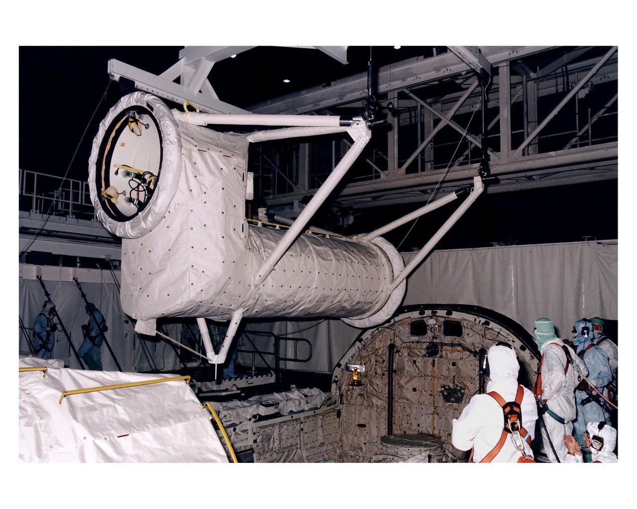
The Spacelab long transfer tunnel that leads from the Space Shuttle Orbiter Columbia’s crew airlock to the Microgravity Science Laboratory-1 (MSL-1) Spacelab module in the spaceplane’s payload bay is removed in Orbiter Processing Facility 1. The tunnel was taken out to allow better access to the MSL-1 module during reservicing operations to prepare it for its reflight as MSL-1R. That mission is now scheduled to lift off July 1. This was the first time that this type of payload was reserviced without removing it from the payload bay. This new procedure pioneers processing efforts for quick relaunch turnaround times for future payloads. The Spacelab module was scheduled to fly again with the full complement of STS-83 experiments after that mission was cut short due to a faulty fuel cell. During the scheduled 16-day reflight, the experiments will be used to test some of the hardware, facilities and procedures that are planned for use on the International Space Station while the flight crew conducts combustion, protein crystal growth and materials processing experiments
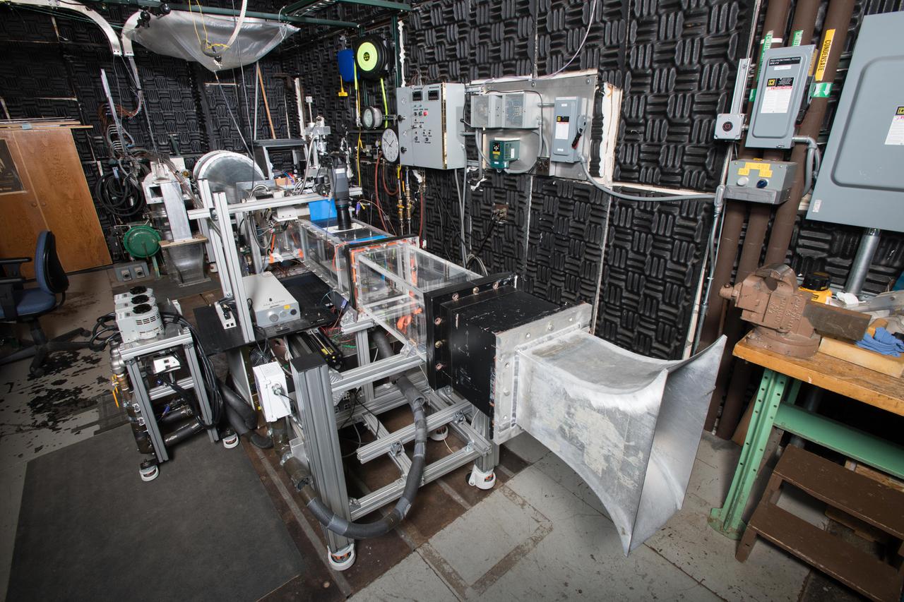
Fundamental Film Cooling and Heat Transfer Facility, Ceramic Matrix Composite High Pressure Turbine Thermal Management Project,
A technician prepares a 2.25 percent scale model of the space shuttle for a base heat study in the 10- by 10-Foot Supersonic Wind Tunnel at the National Aeronautics and Space Administration (NASA) Lewis Research Center. This space shuttle project, begun here in July 1976, was aimed at evaluating base heating and pressure prior to the Shuttle’s first lift-off scheduled for 1979. The space shuttle was expected to experience multifaceted heating and pressure distributions during the first and second stages of its launch. Engineers needed to understand these issues in order to design proper thermal protection. The test’s specific objectives were to measure the heat transfer and pressure distributions around the orbiter’s external tank and solid rocket afterbody caused by rocket exhaust recirculation and impingement, to measure the heat transfer and pressure distributions caused by rocket exhaust-induced separation, and determine gas recovery temperatures using gas temperature probes and heated base components. The shuttle model’s main engines and solid rockets were first fired and then just the main engines to simulate a launch during the testing. Lewis researchers conducted 163 runs in the 10- by 10 during the test program.
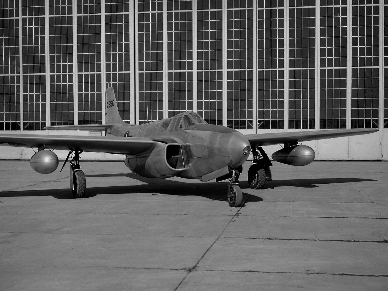
A Bell P-59B Airacomet sits beside the hangar at the National Advisory Committee for Aeronautics (NACA) Lewis Flight Propulsion Laboratory. In 1942 the Bell XP-59A Airacomet became the first jet aircraft in the US. The Airacomet incorporated centrifugal turbojet engines that were based on British plans secretly brought to the US in 1941. A Bell test pilot flew the XP-59A for the first time at Muroc Lake, California in October 1942. The General Electric I-16 engines proved to be problematic. In an effort to increase the engine performance, an Airacomet was secretly brought to Cleveland in early 1944 for testing in the Altitude Wind Tunnel. A series of tunnel investigations in February and March resulted in a 25-percent increase in the I-16 engine’s performance. Nonetheless, Bell’s 66 Airacomets never made it into combat. A second, slightly improved Airacomet, a P-59B, was transferred to NACA Lewis just after the war in September 1945. The P-59B was used over the next three years to study general jet thrust performance and thrust augmentation devices such as afterburners and water/alcohol injection. The P-59B flights determined the proper alcohol and water mixture and injection rate to produce a 21-percent increase in thrust. Since the extra boost would be most useful for takeoffs, a series of ground-based tests with the aircraft ensued. It was determined that the runway length for takeoffs could be reduced by as much as 15 percent. The P-59B used for the tests is now on display at the Air Force Museum at Wright Patterson.
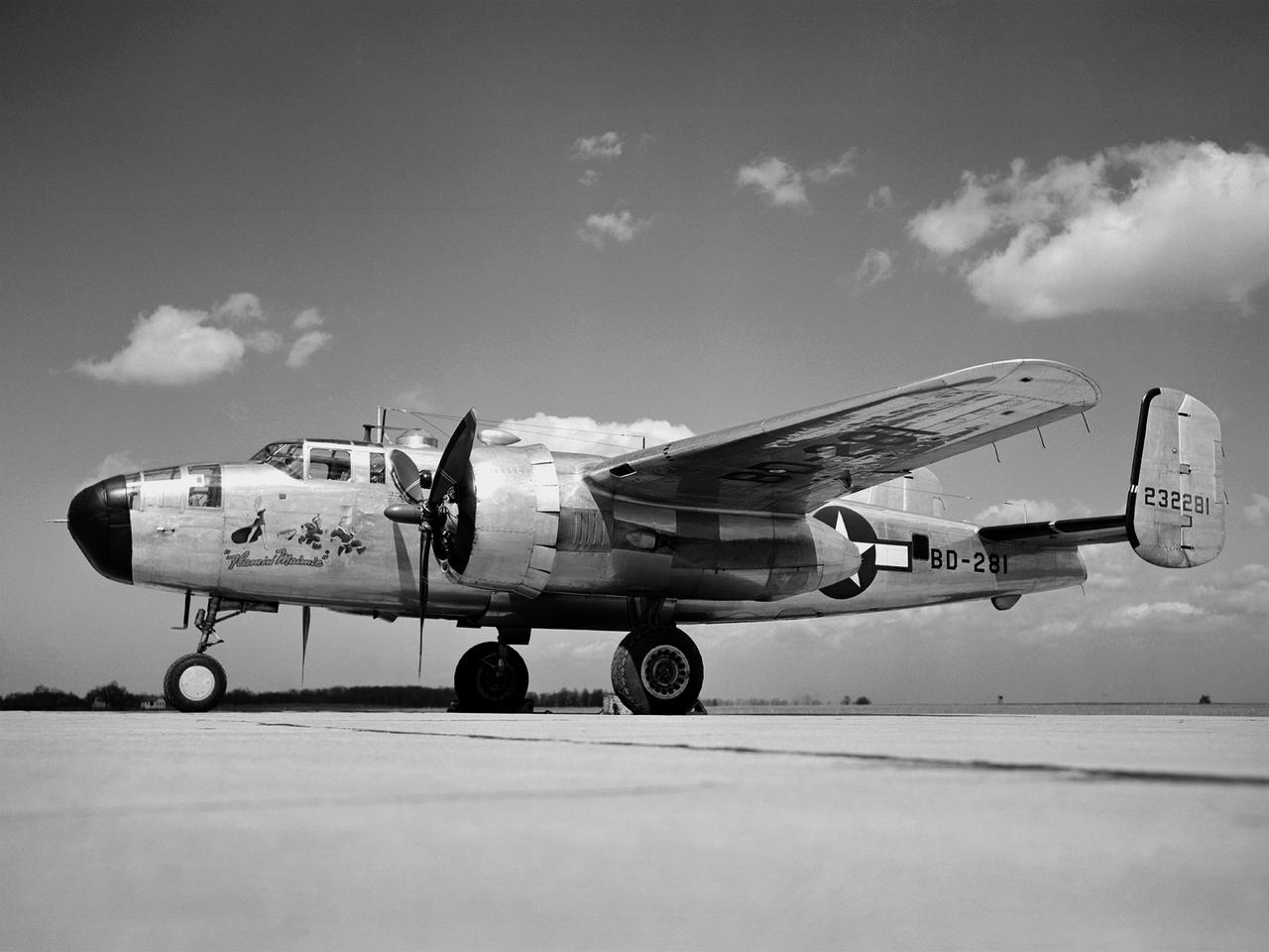
In 1946 the Lewis Flight Propulsion Laboratory became the NACA’s official icing research center. In addition to the Icing Research Tunnel, the lab possessed several aircraft modified for icing work, including a Consolidated B-24M Liberator and a North American XB-25E Mitchell, seen here. The XB-25E’s frequent engine fires allegedly resulted in its “Flamin’ Maimie” nickname. The aircraft’s nose art, visible in this photograph, includes a leather-jacketed mechanic with an extinguisher fleeing a fiery woman. North American developed the B-25 in the mid-1930s as a transport aircraft, but it was hurriedly reconfigured as a medium bomber for World War II. This XB-25E was a single prototype designed in 1942 specifically to test an exhaust gas ice prevention system developed by NACA researcher Lewis Rodert. The system circulated the engines’ hot bleed air to the wings, windshield, and tail. The XB-25E was utilized at the NACA’s Ames Aeronautical Laboratory for two years before being transferred to Cleveland in July 1944. NACA Lewis mechanics modified the aircraft further by installing electrical heating in the front fuselage, propellers, inboard sing, cowls, and antennae. Lewis pilots flew the B-24M and XB-25E into perilous weather conditions all across the country to study both deicing technologies and the physics of ice-producing clouds. These dangerous flights led to advances in weather sensing instruments and flight planning.

One of the two primary coolers at the Propulsion Systems Laboratory at the National Advisory Committee for Aeronautics (NACA) Lewis Flight Propulsion Laboratory. Engines could be run in simulated altitude conditions inside the facility’s two 14-foot-diameter and 24-foot-long test chambers. The Propulsion Systems Laboratory was the nation’s only facility that could run large full-size engine systems in controlled altitude conditions. At the time of this photograph, construction of the facility had recently been completed. Although not a wind tunnel, the Propulsion Systems Laboratory generated high-speed airflow through the interior of the engine. The air flow was pushed through the system by large compressors, adjusted by heating or refrigerating equipment, and de-moisturized by air dryers. The exhaust system served two roles: reducing the density of the air in the test chambers to simulate high altitudes and removing hot gases exhausted by the engines being tested. It was necessary to reduce the temperature of the extremely hot engine exhaust before the air reached the exhauster equipment. As the air flow exited through exhaust section of the test chamber, it entered into the giant primary cooler seen in this photograph. Narrow fins or vanes inside the cooler were filled with water. As the air flow passed between the vanes, its heat was transferred to the cooling water. The cooling water was cycled out of the system, carrying with it much of the exhaust heat.
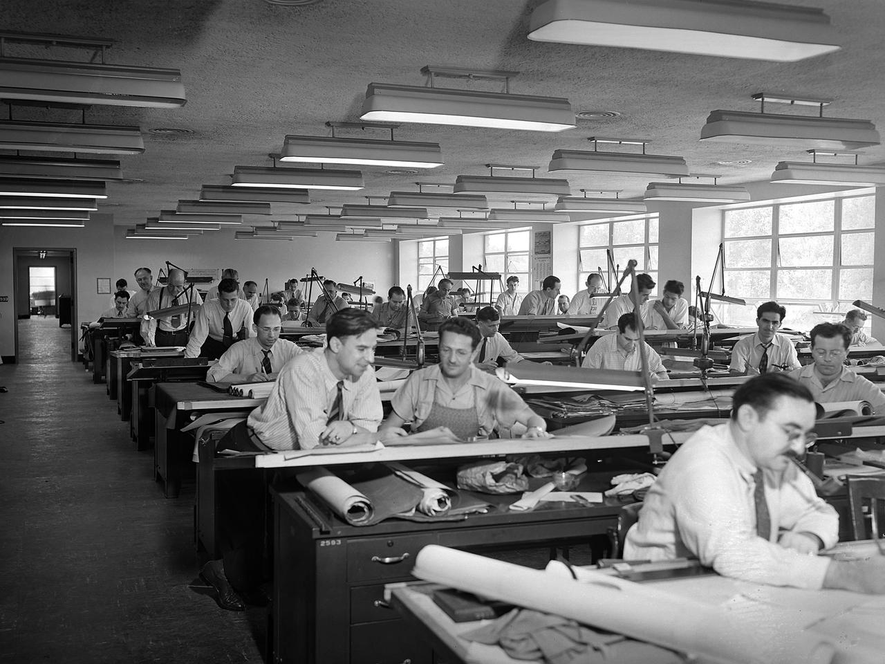
The National Advisory Committee for Aeronautics (NACA) Aircraft Engine Research Laboratory was designed by a group of engineers at the Langley Memorial Aeronautical Laboratory in late 1940 and 1941. Under the guidance of Ernest Whitney, the men worked on drawings and calculations in a room above Langley’s Structural Research Laboratory. The main Aircraft Engine Research Laboratory design group originally consisted of approximately 30 engineers and draftsmen, but there were smaller groups working separately on specific facilities. The new engine lab would have six principal buildings: the Engine Research Building, hangar, Fuels and Lubricants Building, Administration Building, Propeller Test Stand, and Altitude Wind Tunnel. In December 1941 most of those working on the project transferred to Cleveland from Langley. Harrison Underwood and Charles Egan led 18 architectural, 26 machine equipment, 3 structural and 10 mechanical draftsmen. Initially these staff members were housed in temporary offices in the hangar. As sections of the four-acre Engine Research Building were completed in the summer of 1942, the design team began relocating there. The Engine Research Building contained a variety of test cells and laboratories to address virtually every aspect of piston engine research. It also contained a two-story office wing, seen in this photograph that would later house many of the powerplant research engineers.

The XV-15 tilt rotor ships #1 and #2 parked on the NASA Dryden Flight Research Center ramp. The XV-15s, manufactured by Bell, were involved in limited research at Dryden in 1980 and 1981. The development of the XV-15 Tiltrotor research aircraft was initiated in 1973 with joint Army/NASA funding as a "proof of concept", or "technology demonstrator" program, with two aircraft being built by Bell Helicopter Textron (BHT) in 1977. The aircraft are powered by twin Lycoming T-53 turboshaft engines that are connected by a cross-shaft and drive three-bladed, 25 ft diameter metal rotors (the size extensively tested in a wind tunnel). The engines and main transmissions are located in wingtip nacelles to minimize the operational loads on the cross-shaft system and, with the rotors, tilt as a single unit. For takeoff, the proprotors and their engines are used in the straight-up position where the thrust is directed downward. The XV-15 then climbs vertically into the air like a helicopter. In this VTOL mode, the vehicle can lift off and hover for approximately one hour. Once off the ground, the XV-15 has the ability to fly in one of two different modes. It can fly as a helicopter, in the partially converted airplane mode. The XV-15 can also then convert from the helicopter mode to the airplane mode. This is accomplished by continuous rotation of the proprotors from the helicopter rotor position to the conventional airplane propeller position. During the ten to fifteen second conversion period, the aircraft speed increases and lift is transferred from the rotors to the wing. To land, the proprotors are rotated up to the helicopter rotor position and flown as a helicopter to a vertical landing.