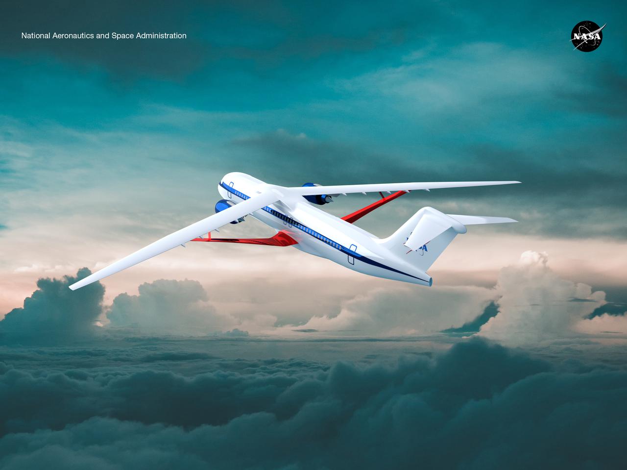
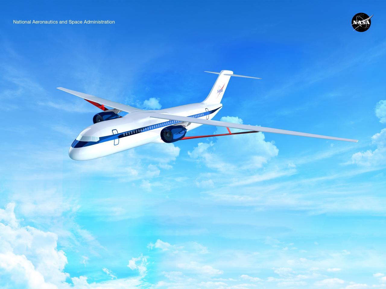
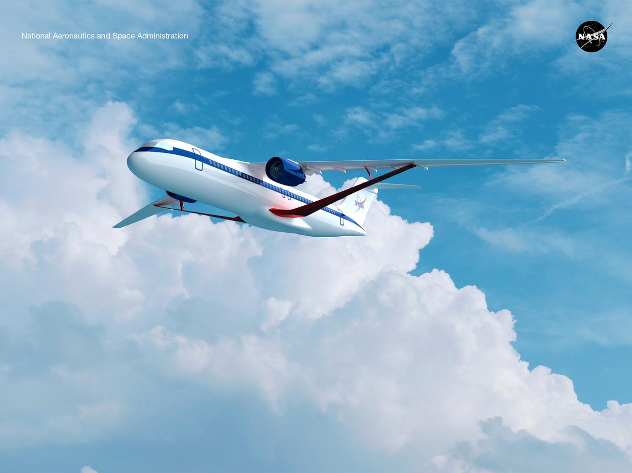
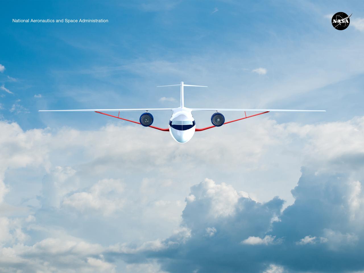
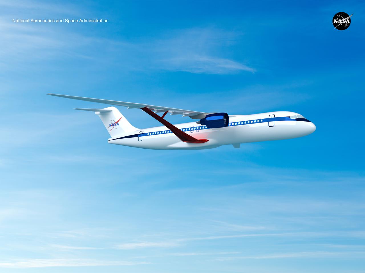
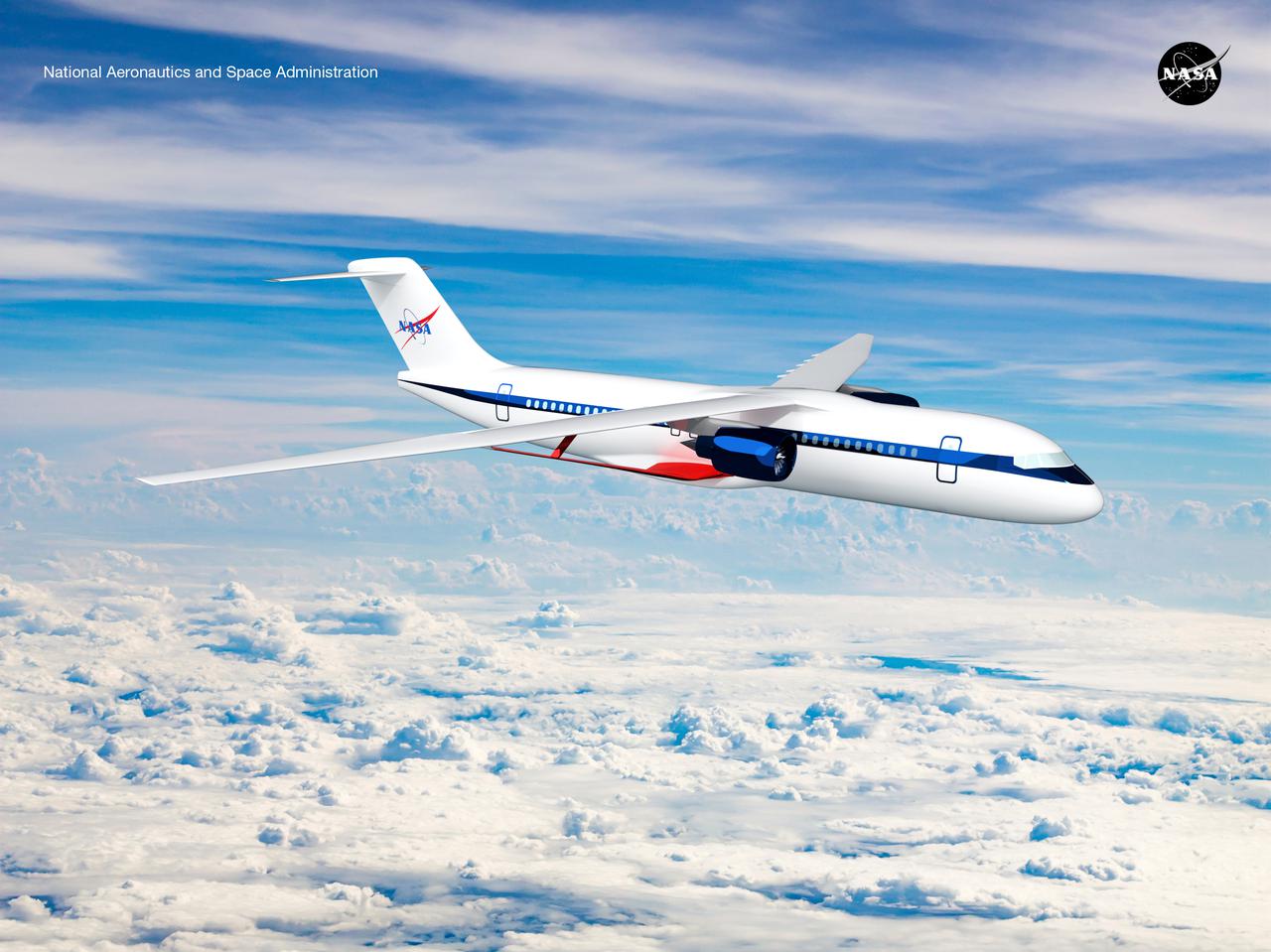
Notice anything different about the wings on this airliner? This conceptual truss-braced wing narrowbody is an aircraft with a 170ft span folding wing. By utilizing trusses, the aircraft can have longer, thinner wings with greater aspect ratios. This, in turn, translates into less drag and 5-10% less fuel burned. The Transonic Truss-Braced Wing aircraft originated from a joint effort by NASA and Boeing to develop subsonic commercial transport concepts – meeting NASA-defined metrics in terms of reduced noise, emissions, and fuel consumption. The design is currently undergoing wind tunnel testing and other studies by NASA researchers.
Notice anything different about the wings on this airliner? This conceptual truss-braced wing narrowbody is an aircraft with a 170ft span folding wing. By utilizing trusses, the aircraft can have longer, thinner wings with greater aspect ratios. This, in turn, translates into less drag and 5-10% less fuel burned. The Transonic Truss-Braced Wing aircraft originated from a joint effort by NASA and Boeing to develop subsonic commercial transport concepts – meeting NASA-defined metrics in terms of reduced noise, emissions, and fuel consumption. The design is currently undergoing wind tunnel testing and other studies by NASA researchers.
Notice anything different about the wings on this airliner? This conceptual truss-braced wing narrowbody is an aircraft with a 170ft span folding wing. By utilizing trusses, the aircraft can have longer, thinner wings with greater aspect ratios. This, in turn, translates into less drag and 5-10% less fuel burned. The Transonic Truss-Braced Wing aircraft originated from a joint effort by NASA and Boeing to develop subsonic commercial transport concepts – meeting NASA-defined metrics in terms of reduced noise, emissions, and fuel consumption. The design is currently undergoing wind tunnel testing and other studies by NASA researchers.
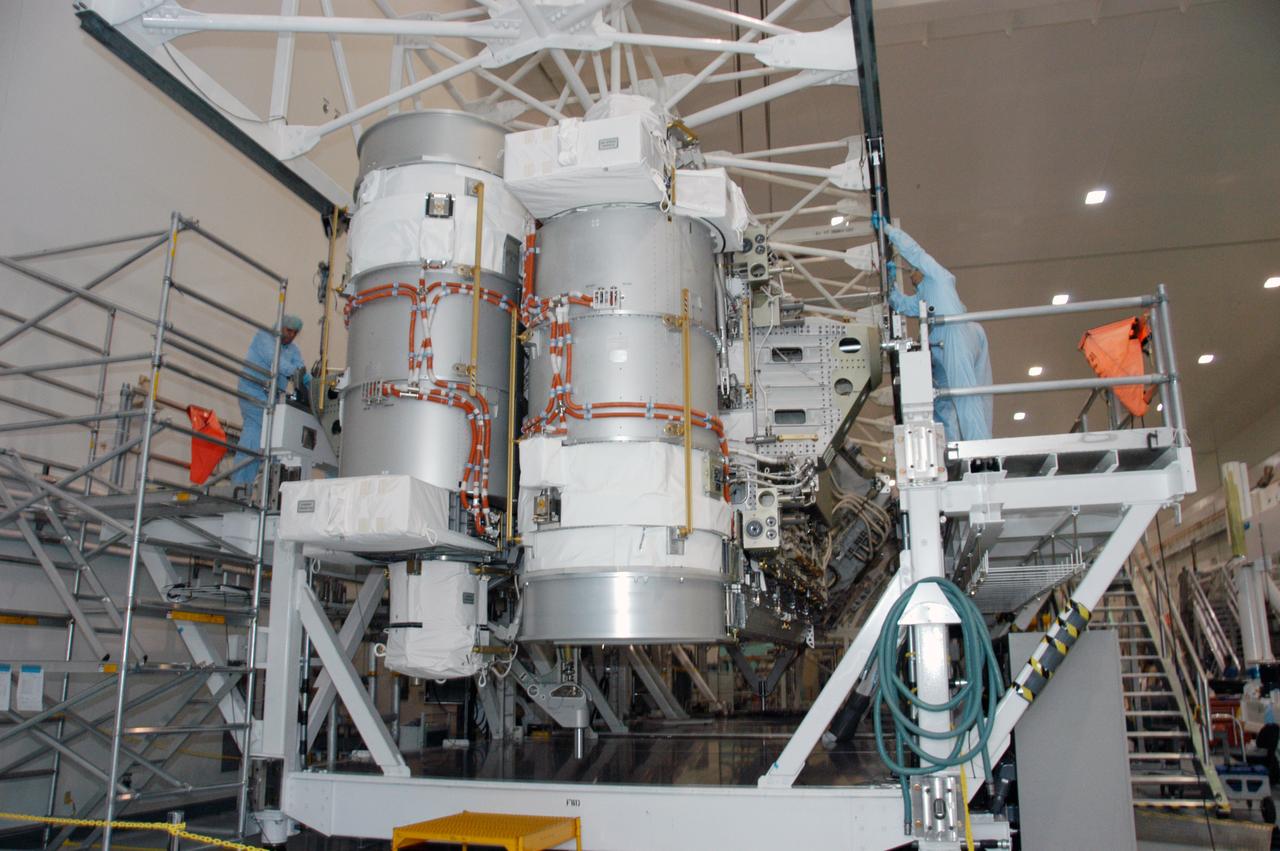
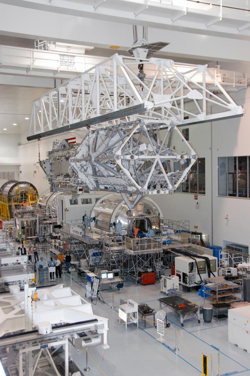
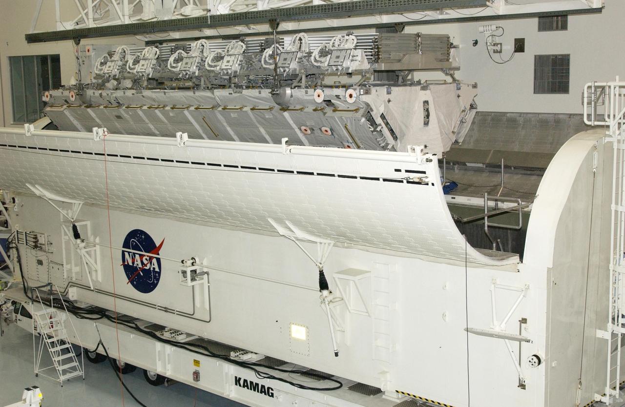
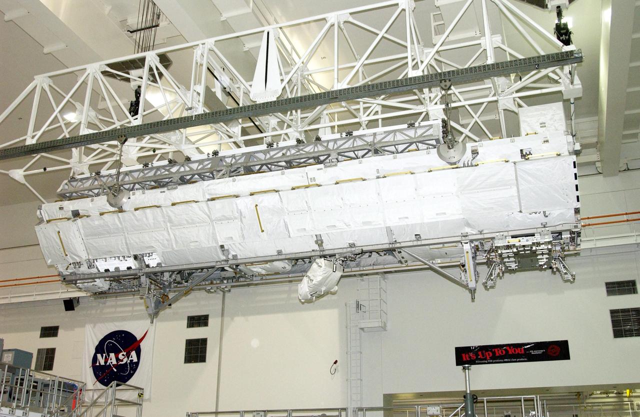
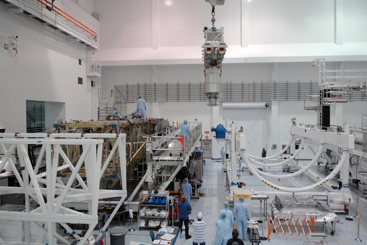
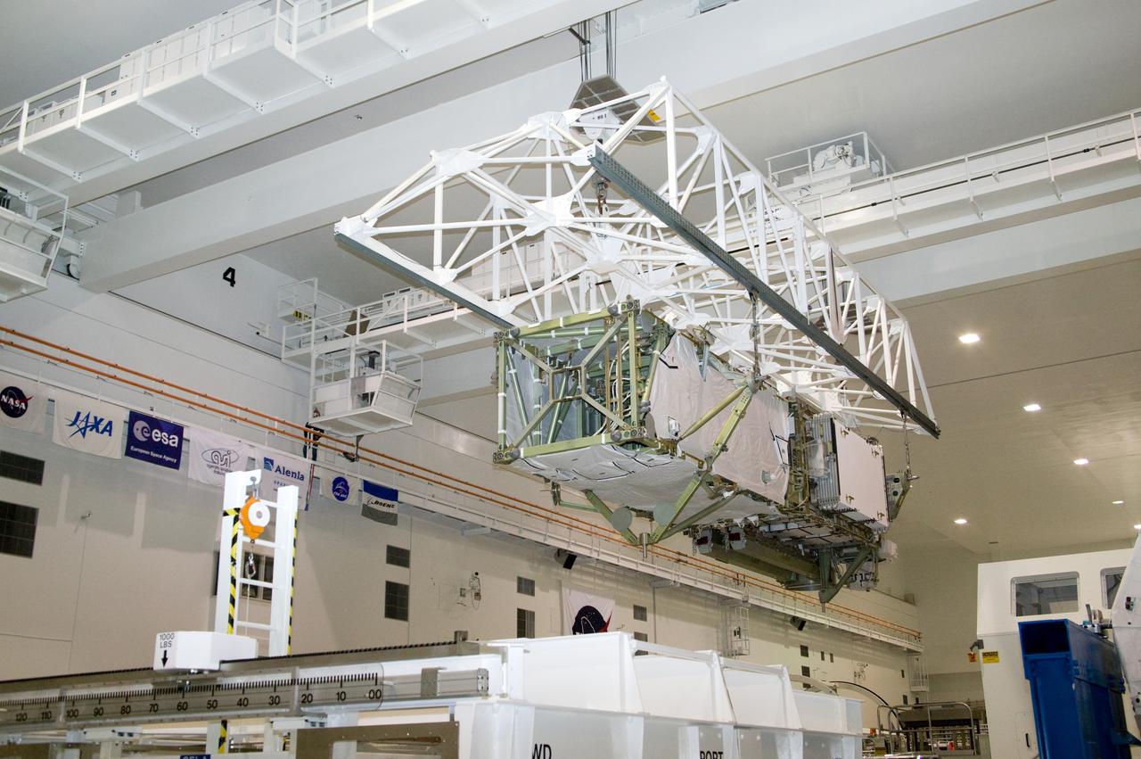
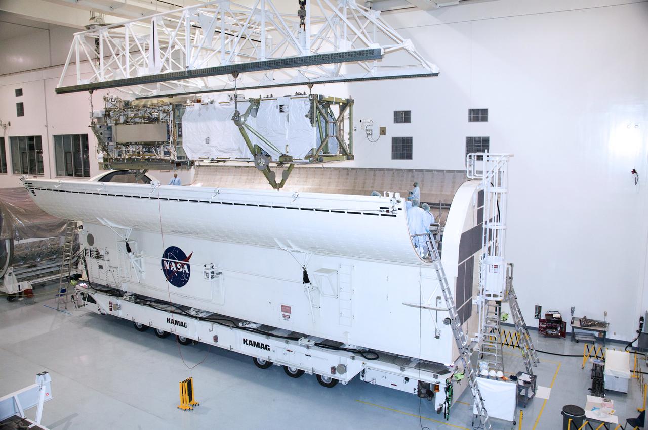
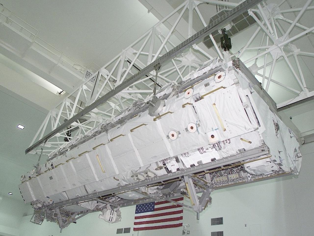
In the Space Station Processing Facility, workers attach an overhead crane to the S3/S4 integrated truss in order to move it to the payload canister. After it is stowed in the canister, the S3/S4 truss will be transported to the launch pad. The truss is the payload on mission STS-117, targeted for launch on March 15.
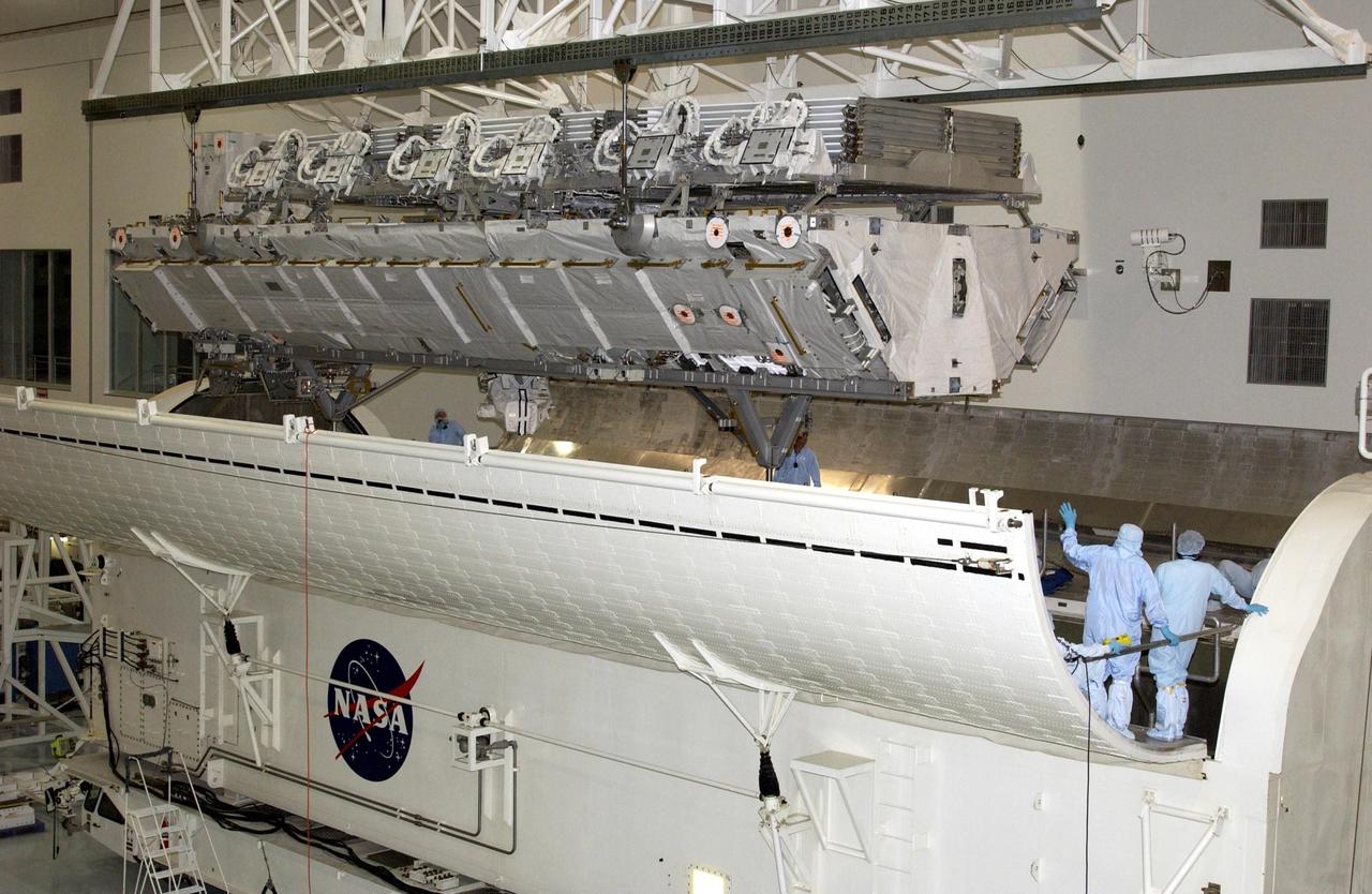
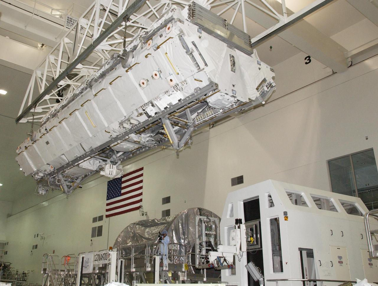
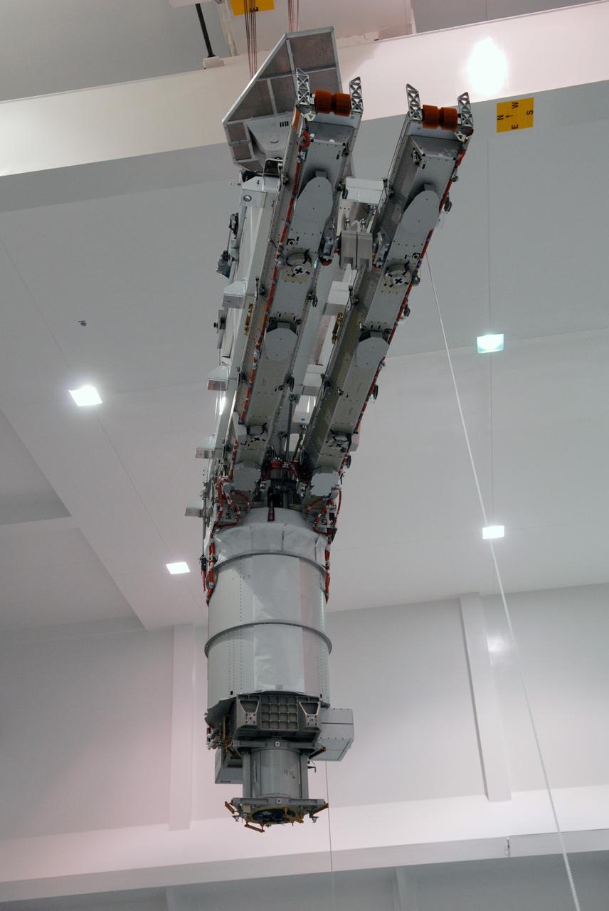
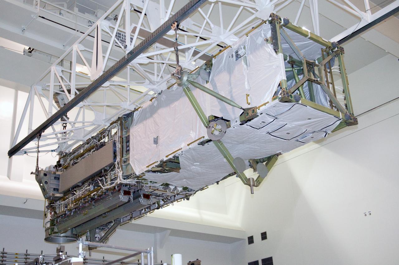
In the Space Station Processing Facility, an overhead crane lowers the S3/S4 integrated truss toward the open doors of the payload canister. After it is stowed in the canister, the S3/S4 truss will be transported to the launch pad. The truss is the payload on mission STS-117, targeted for launch on March 15.
In the Space Station Processing Facility, an overhead crane lowers the S3/S4 integrated truss into the open bay of the payload canister. After it is stowed in the canister, the S3/S4 truss will be transported to the launch pad. The truss is the payload on mission STS-117, targeted for launch on March 15.
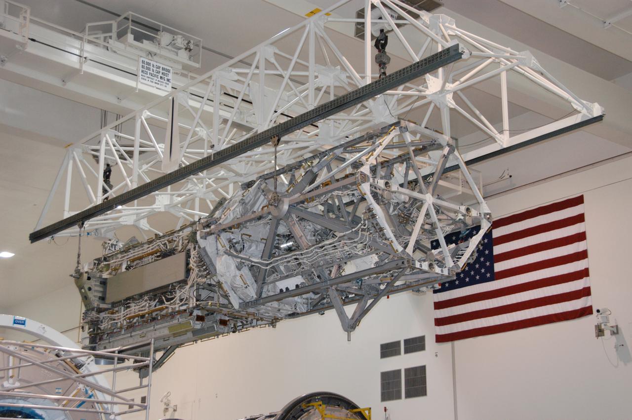
In the Space Station Processing Facility, an overhead crane moves the S3/S4 integrated truss to a payload canister. After it is stowed in the canister, the S3/S4 truss will be transported to the launch pad. The truss is the payload on mission STS-117, targeted for launch on March 15.
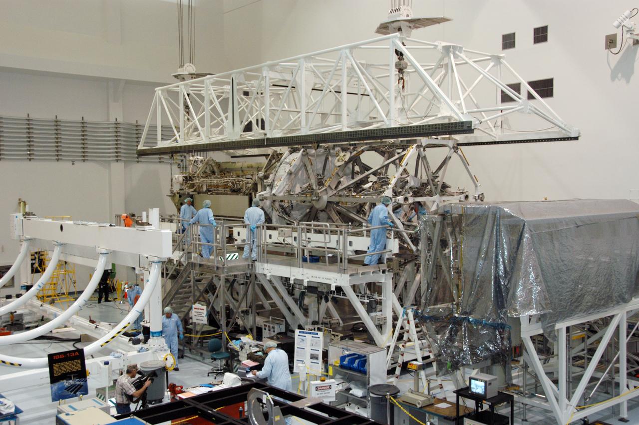
In the Space Station Processing Facility, workers attach an overhead crane to the S3/S4 integrated truss in order to move it to the payload canister. After it is stowed in the canister, the S3/S4 truss will be transported to the launch pad. The truss is the payload on mission STS-117, targeted for launch on March 15.
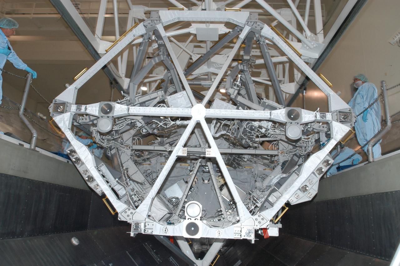
In the Space Station Processing Facility, an overhead crane settles the S3/S4 integrated truss into the payload canister. After it is stowed in the canister, the S3/S4 truss will be transported to the launch pad. The truss is the payload on mission STS-117, targeted for launch on March 15.
Notice anything different about the wings on this airliner? This conceptual truss-braced wing narrowbody is an aircraft with a 170ft span folding wing. By utilizing trusses, the aircraft can have longer, thinner wings with greater aspect ratios. This, in turn, translates into less drag and 5-10% less fuel burned. The Transonic Truss-Braced Wing aircraft originated from a joint effort by NASA and Boeing to develop subsonic commercial transport concepts – meeting NASA-defined metrics in terms of reduced noise, emissions, and fuel consumption. The design is currently undergoing wind tunnel testing and other studies by NASA researchers.
Notice anything different about the wings on this airliner? This conceptual truss-braced wing narrowbody is an aircraft with a 170ft span folding wing. By utilizing trusses, the aircraft can have longer, thinner wings with greater aspect ratios. This, in turn, translates into less drag and 5-10% less fuel burned. The Transonic Truss-Braced Wing aircraft originated from a joint effort by NASA and Boeing to develop subsonic commercial transport concepts – meeting NASA-defined metrics in terms of reduced noise, emissions, and fuel consumption. The design is currently undergoing wind tunnel testing and other studies by NASA researchers.
Notice anything different about the wings on this airliner? This conceptual truss-braced wing narrowbody is an aircraft with a 170ft span folding wing. By utilizing trusses, the aircraft can have longer, thinner wings with greater aspect ratios. This, in turn, translates into less drag and 5-10% less fuel burned. The Transonic Truss-Braced Wing aircraft originated from a joint effort by NASA and Boeing to develop subsonic commercial transport concepts – meeting NASA-defined metrics in terms of reduced noise, emissions, and fuel consumption. The design is currently undergoing wind tunnel testing and other studies by NASA researchers.
Notice anything different about the wings on this airliner? This conceptual truss-braced wing narrowbody is an aircraft with a 170ft span folding wing. By utilizing trusses, the aircraft can have longer, thinner wings with greater aspect ratios. This, in turn, translates into less drag and 5-10% less fuel burned. The Transonic Truss-Braced Wing aircraft originated from a joint effort by NASA and Boeing to develop subsonic commercial transport concepts – meeting NASA-defined metrics in terms of reduced noise, emissions, and fuel consumption. The design is currently undergoing wind tunnel testing and other studies by NASA researchers.
Notice anything different about the wings on this airliner? This conceptual truss-braced wing narrowbody is an aircraft with a 170ft span folding wing. By utilizing trusses, the aircraft can have longer, thinner wings with greater aspect ratios. This, in turn, translates into less drag and 5-10% less fuel burned. The Transonic Truss-Braced Wing aircraft originated from a joint effort by NASA and Boeing to develop subsonic commercial transport concepts – meeting NASA-defined metrics in terms of reduced noise, emissions, and fuel consumption. The design is currently undergoing wind tunnel testing and other studies by NASA researchers.
Notice anything different about the wings on this airliner? This conceptual truss-braced wing narrowbody is an aircraft with a 170ft span folding wing. By utilizing trusses, the aircraft can have longer, thinner wings with greater aspect ratios. This, in turn, translates into less drag and 5-10% less fuel burned. The Transonic Truss-Braced Wing aircraft originated from a joint effort by NASA and Boeing to develop subsonic commercial transport concepts – meeting NASA-defined metrics in terms of reduced noise, emissions, and fuel consumption. The design is currently undergoing wind tunnel testing and other studies by NASA researchers.
Notice anything different about the wings on this airliner? This conceptual truss-braced wing narrowbody is an aircraft with a 170ft span folding wing. By utilizing trusses, the aircraft can have longer, thinner wings with greater aspect ratios. This, in turn, translates into less drag and 5-10% less fuel burned. The Transonic Truss-Braced Wing aircraft originated from a joint effort by NASA and Boeing to develop subsonic commercial transport concepts – meeting NASA-defined metrics in terms of reduced noise, emissions, and fuel consumption. The design is currently undergoing wind tunnel testing and other studies by NASA researchers.
Notice anything different about the wings on this airliner? This conceptual truss-braced wing narrowbody is an aircraft with a 170ft span folding wing. By utilizing trusses, the aircraft can have longer, thinner wings with greater aspect ratios. This, in turn, translates into less drag and 5-10% less fuel burned. The Transonic Truss-Braced Wing aircraft originated from a joint effort by NASA and Boeing to develop subsonic commercial transport concepts – meeting NASA-defined metrics in terms of reduced noise, emissions, and fuel consumption. The design is currently undergoing wind tunnel testing and other studies by NASA researchers.
Notice anything different about the wings on this airliner? This conceptual truss-braced wing narrowbody is an aircraft with a 170ft span folding wing. By utilizing trusses, the aircraft can have longer, thinner wings with greater aspect ratios. This, in turn, translates into less drag and 5-10% less fuel burned. The Transonic Truss-Braced Wing aircraft originated from a joint effort by NASA and Boeing to develop subsonic commercial transport concepts – meeting NASA-defined metrics in terms of reduced noise, emissions, and fuel consumption. The design is currently undergoing wind tunnel testing and other studies by NASA researchers.
Notice anything different about the wings on this airliner? This conceptual truss-braced wing narrowbody is an aircraft with a 170ft span folding wing. By utilizing trusses, the aircraft can have longer, thinner wings with greater aspect ratios. This, in turn, translates into less drag and 5-10% less fuel burned. The Transonic Truss-Braced Wing aircraft originated from a joint effort by NASA and Boeing to develop subsonic commercial transport concepts – meeting NASA-defined metrics in terms of reduced noise, emissions, and fuel consumption. The design is currently undergoing wind tunnel testing and other studies by NASA researchers.
Notice anything different about the wings on this airliner? This conceptual truss-braced wing narrowbody is an aircraft with a 170ft span folding wing. By utilizing trusses, the aircraft can have longer, thinner wings with greater aspect ratios. This, in turn, translates into less drag and 5-10% less fuel burned. The Transonic Truss-Braced Wing aircraft originated from a joint effort by NASA and Boeing to develop subsonic commercial transport concepts – meeting NASA-defined metrics in terms of reduced noise, emissions, and fuel consumption. The design is currently undergoing wind tunnel testing and other studies by NASA researchers.
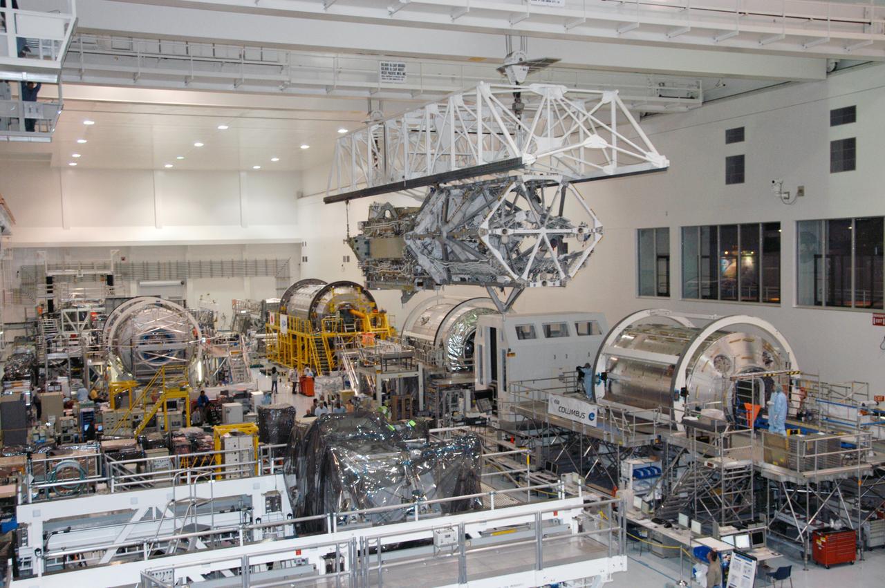
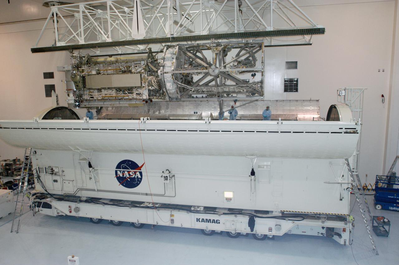
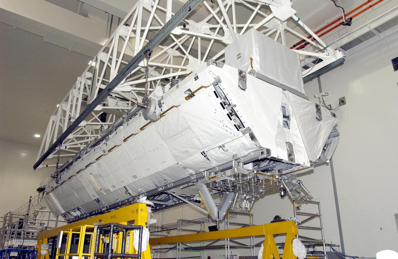
In the Space Station Processing Facility, an overhead crane moves the S3/S4 integrated truss above the floor to a payload canister. Several space station modules can be seen at various points on the floor. After it is stowed in the canister, the S3/S4 truss will be transported to the launch pad. The truss is the payload on mission STS-117, targeted for launch on March 15.
In the Space Station Processing Facility, an overhead crane moves the S3/S4 integrated truss above the floor to a payload canister. Several space station modules can be seen at various points on the floor. After it is stowed in the canister, the S3/S4 truss will be transported to the launch pad. The truss is the payload on mission STS-117, targeted for launch on March 15.
Notice anything different about the wings on this airliner? This conceptual truss-braced wing narrowbody is an aircraft with a 170ft span folding wing. By utilizing trusses, the aircraft can have longer, thinner wings with greater aspect ratios. This, in turn, translates into less drag and 5-10% less fuel burned. The Transonic Truss-Braced Wing aircraft originated from a joint effort by NASA and Boeing to develop subsonic commercial transport concepts – meeting NASA-defined metrics in terms of reduced noise, emissions, and fuel consumption. The design is currently undergoing wind tunnel testing and other studies by NASA researchers.
Notice anything different about the wings on this airliner? This conceptual truss-braced wing narrowbody is an aircraft with a 170ft span folding wing. By utilizing trusses, the aircraft can have longer, thinner wings with greater aspect ratios. This, in turn, translates into less drag and 5-10% less fuel burned. The Transonic Truss-Braced Wing aircraft originated from a joint effort by NASA and Boeing to develop subsonic commercial transport concepts – meeting NASA-defined metrics in terms of reduced noise, emissions, and fuel consumption. The design is currently undergoing wind tunnel testing and other studies by NASA researchers.
KENNEDY SPACE CENTER, FLA. -- The S1 Integrated Truss Structure is lowered into the payload canister for transport to Atlantis. The first starboard truss segment, the S1 will be attached to the Central truss segment, the S0 Truss, on the International Space Station during mission STS-112. Atlantis is scheduled to launch no earlier than Oct. 2.
KENNEDY SPACE CENTER, FLA. - Workers inside the payload canister watch the S1 Integrated Truss Structure as it is lowered toward them. The canister will transport the truss to Atlantis. The first starboard truss segment, the S1 will be attached to the Central truss segment, the S0 Truss, on the International Space Station during mission STS-112. Atlantis is scheduled to launch no earlier than Oct. 2.
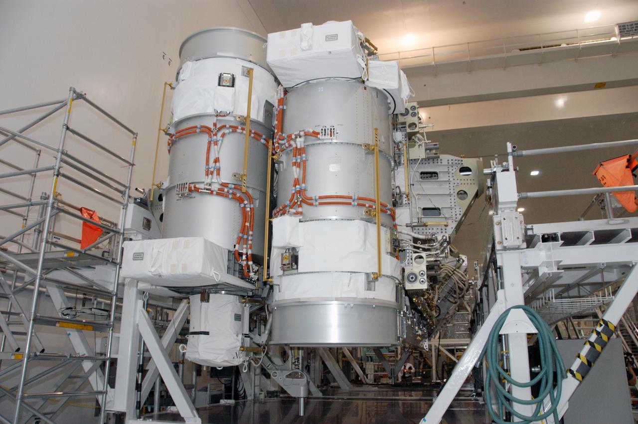
In the Space Station Processing Facility, the S3/S4 integrated truss segment is on display for the media. The starboard 3/4 truss segment will launch aboard Space Shuttle Atlantis on mission STS-117, targeted for March 15. The element will be added to the 11-segment integrated truss structure, the station's backbone. The integrated truss structure eventually will span more than 300 feet. The S3/S4 truss has two large solar arrays and will provide one-fourth of the total power generation for the completed station.
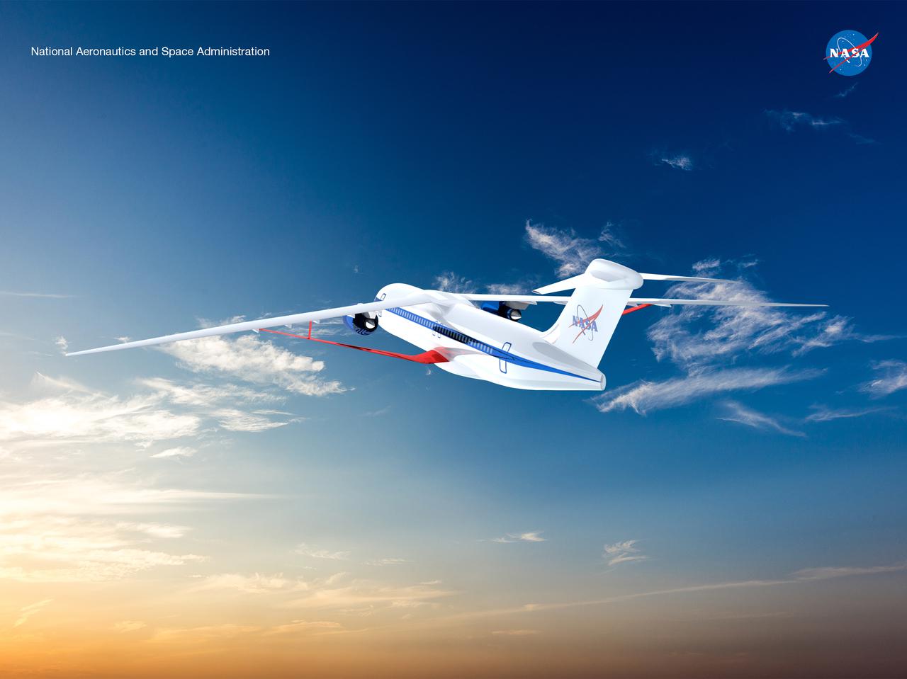
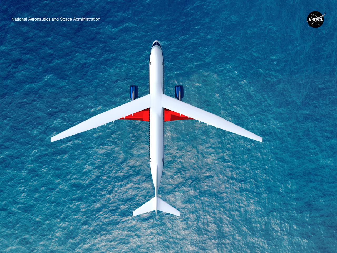
An artist’s concept of the transonic truss-braced wing aircraft configuration in flight over a forest of trees.
An artist’s concept of the transonic truss-braced wing aircraft configuration in flight over a forest of trees.
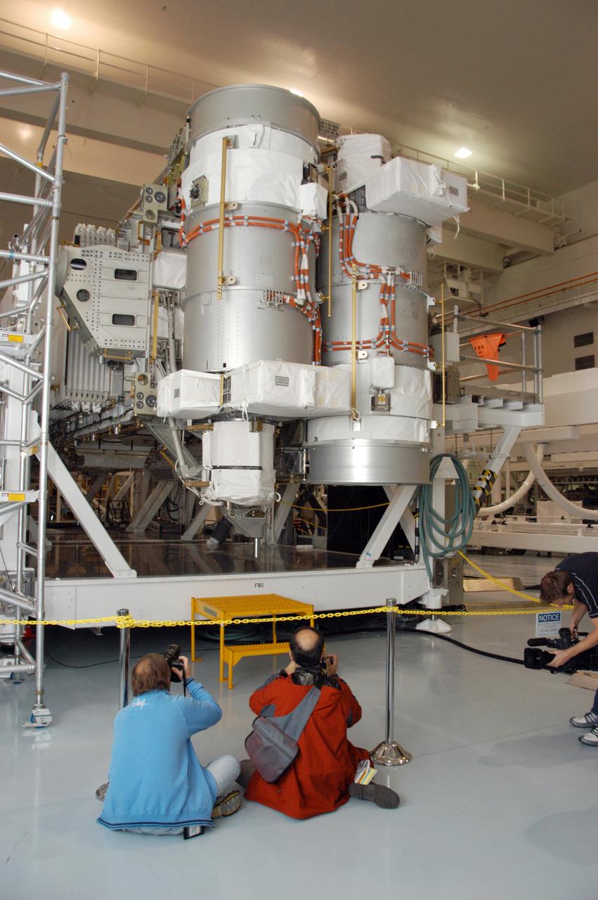
In the Space Station Processing Facility, photographers take advantage of a media showcase to get photos of the S3/S4 integrated truss segment. The starboard 3/4 truss segment will launch aboard Space Shuttle Atlantis on mission STS-117, targeted for March 15. The element will be added to the 11-segment integrated truss structure, the station's backbone. The integrated truss structure eventually will span more than 300 feet. The S3/S4 truss has two large solar arrays and will provide one-fourth of the total power generation for the completed station.
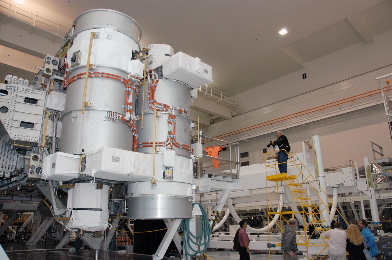
At a media showcase in the Space Station Processing Facility, reporters and photographers get a close look at the S3/S4 integrated truss segment. The starboard 3/4 truss segment will launch aboard Space Shuttle Atlantis on mission STS-117, targeted for March 15. The element will be added to the 11-segment integrated truss structure, the station's backbone. The integrated truss structure eventually will span more than 300 feet. The S3/S4 truss has two large solar arrays and will provide one-fourth of the total power generation for the completed station.
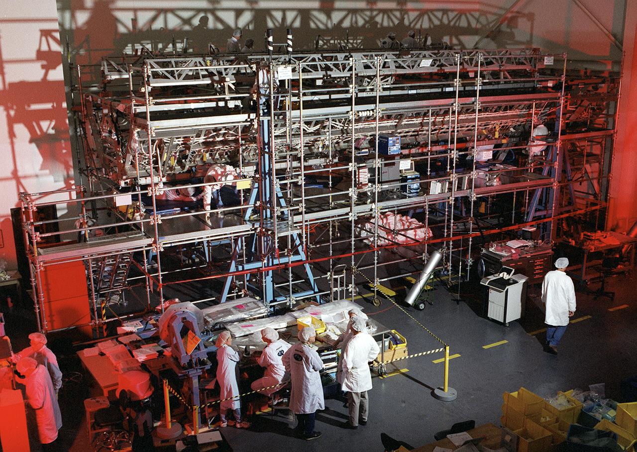
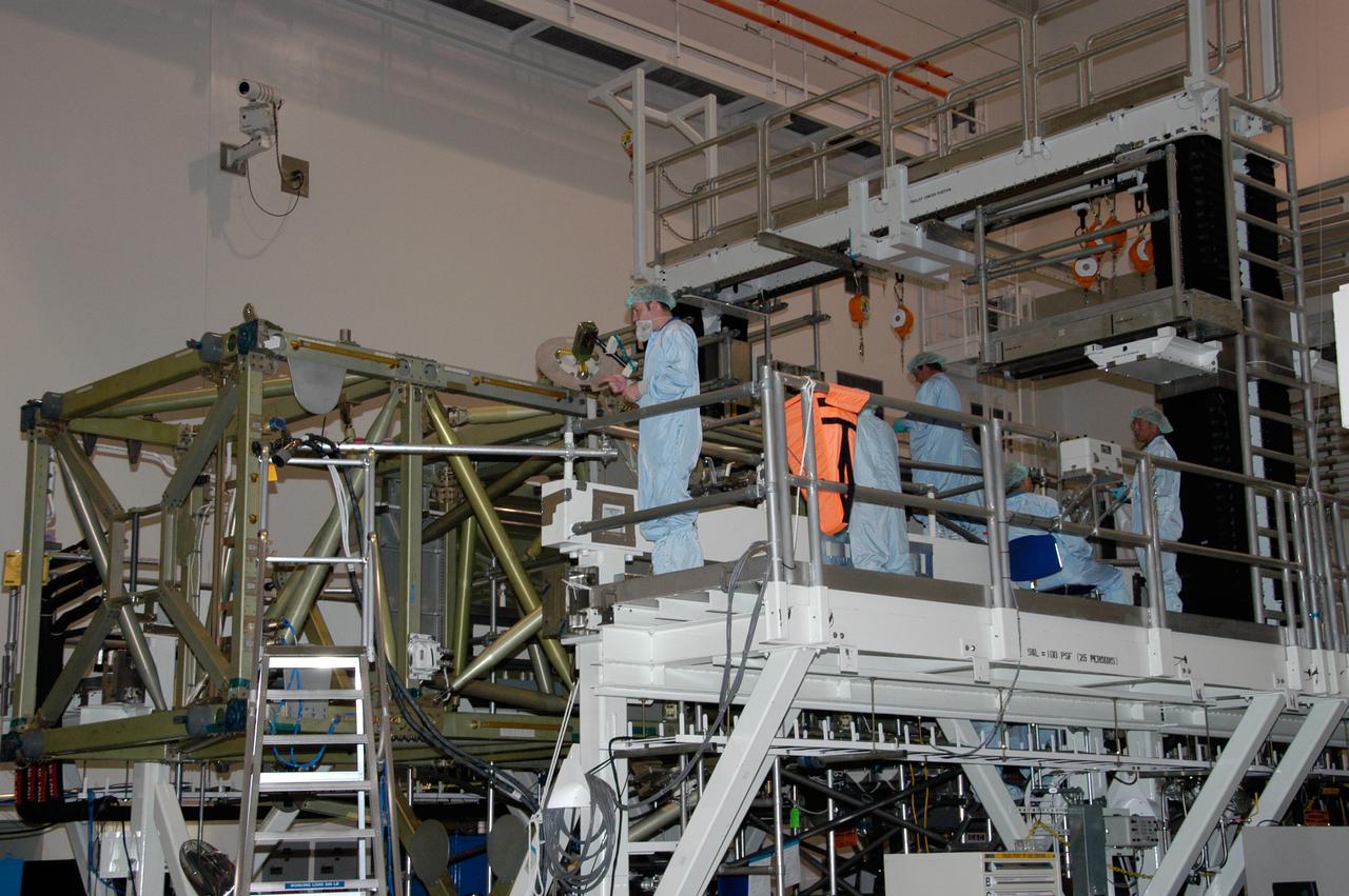
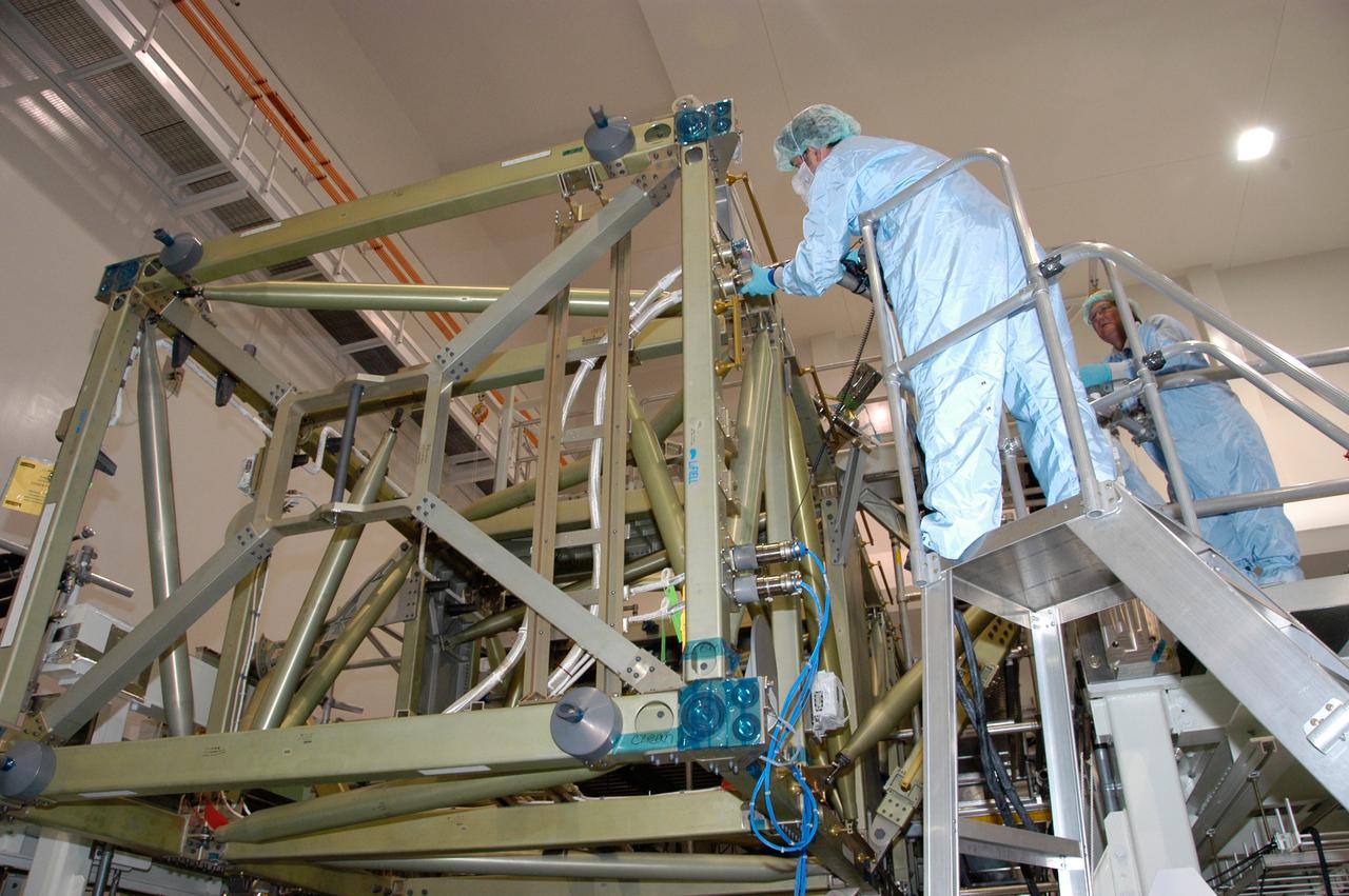
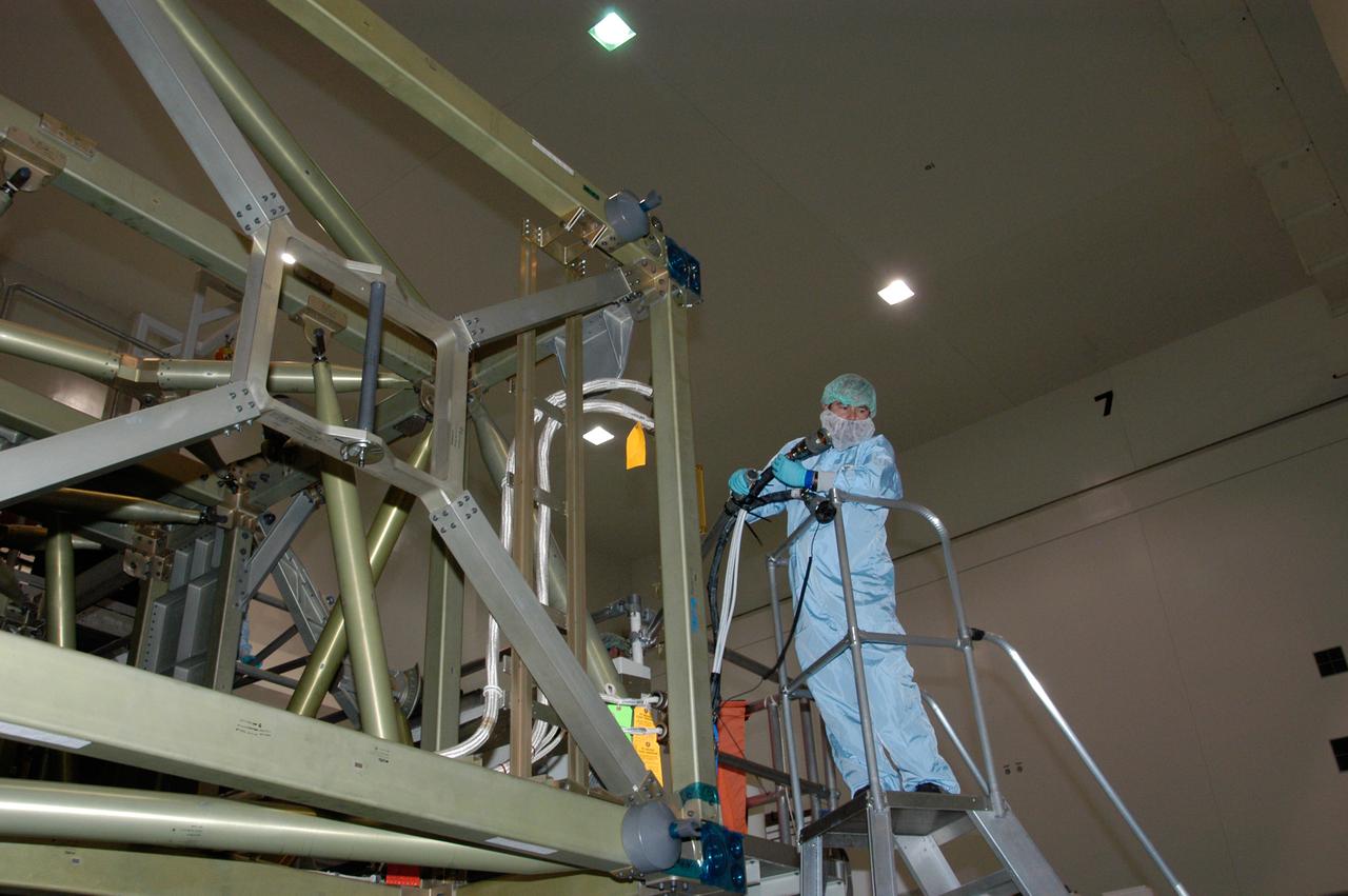
Boeing Company technicians assemble the S-1 truss (starboard side truss) for the International Space Station at the Marshall Space Flight Center.
KENNEDY SPACE CENTER, FLA. -- An overhead crane lifts the S1 Integrated Truss Structure from its workstand. The S1 will be placed in the payload canister for transport it to Atlantis. The first starboard truss segment, the S1 will be attached to the Central truss segment, the S0 Truss, on the International Space Station during mission STS-112. Atlantis is scheduled to launch no earlier than Oct. 2.
KENNEDY SPACE CENTER, FLA. -- An overhead crane moves the S1 Integrated Truss Structure toward the payload canister below, which will transport it to Atlantis. The first starboard truss segment, the S1 will be attached to the Central truss segment, the S0 Truss, on the International Space Station during mission STS-112. Atlantis is scheduled to launch no earlier than Oct. 2.
KENNEDY SPACE CENTER, FLA. -- An overhead crane moves the S1 Integrated Truss Structure toward the payload canister, which will transport it to Atlantis. The first starboard truss segment, the S1 will be attached to the Central truss segment, the S0 Truss, on the International Space Station during mission STS-112. Atlantis is scheduled to launch no earlier than Oct. 2.
KENNEDY SPACE CENTER, FLA. -- An overhead crane moves the S1 Integrated Truss Structure above over other equipment to get to the payload canister for transport to Atlantis. The first starboard truss segment, the S1 will be attached to the Central truss segment, the S0 Truss, on the International Space Station during mission STS-112. Atlantis is scheduled to launch no earlier than Oct. 2.
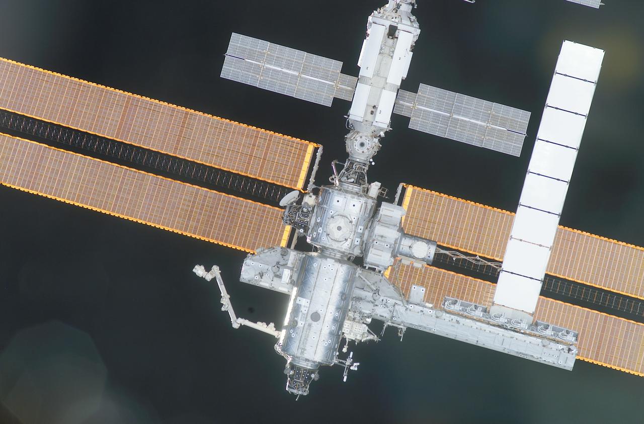
ISS040-E-123158 (2 Sept. 2014) --- A portion of the Russian segment of the International Space Station is featured in this image photographed by an Expedition 40 crew member onboard the station. A blue and white part of Earth and the blackness of space provide the backdrop for the scene.
ISS040-E-123162 (2 Sept. 2014) --- A portion of the Russian segment of the International Space Station is featured in this image photographed by an Expedition 40 crew member onboard the station. A blue and white part of Earth and the blackness of space provide the backdrop for the scene.
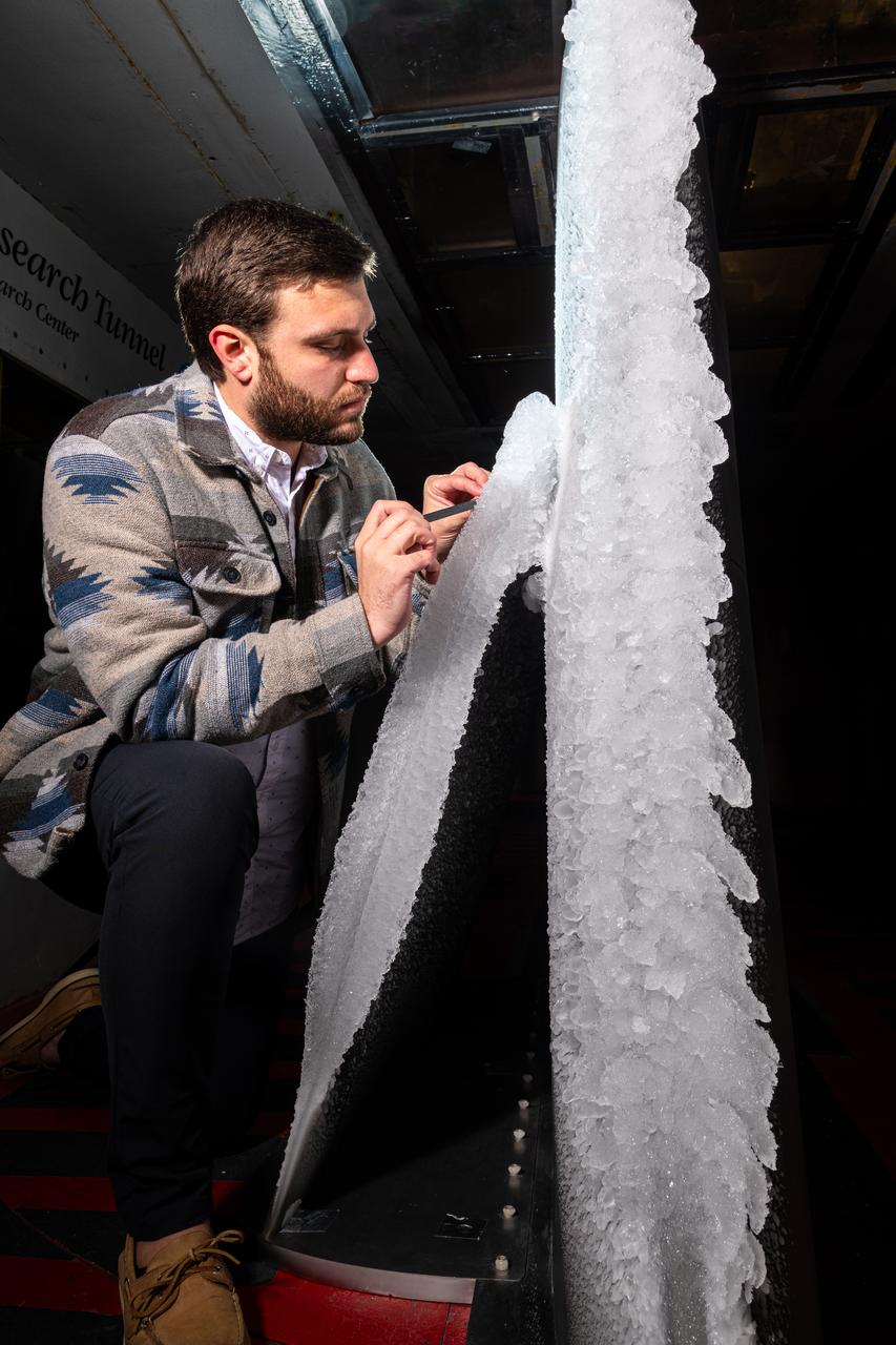
Thomas Ozoroski, an Icing Researcher, is shown documenting ice accretion on the leading edge of the next-generation Transonic Truss-Braced Wing design at NASA Glenn's Icing Research Center. This critical research will help understand icing effects for future, high-lift, ultra-efficient aircraft. Photo Credit: (NASA/Jordan Salkin)
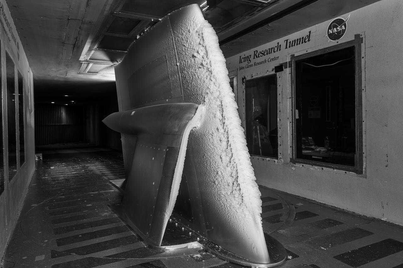
Ice accretion is shown on the leading edge of the next-generation Transonic Truss-Braced Wing design at NASA Glenn's Icing Research Center. This critical research will help understand icing effects for future, high-lift, ultra-efficient aircraft. Photo Credit: (NASA/Jordan Salkin)
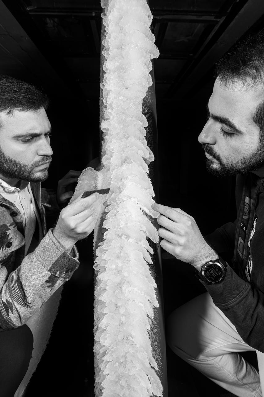
Zaid Sabri and Thomas Ozoroski, Icing Researchers, are shown documenting ice accretion on the leading edge of the next-generation Transonic Truss-Braced Wing design at NASA Glenn's Icing Research Center. This critical research will help understand icing effects for future, high-lift, ultra-efficient aircraft. Photo Credit: (NASA/Jordan Salkin)
This image shows the Integrated Truss Assembly S-1 (S-One), the Starboard Side Thermal Radiator Truss, for the International Space Station (ISS) undergoing final construction in the Space Station manufacturing facility at the Marshall Space Flight Center. The S1 truss provides structural support for the orbiting research facility's radiator panels, which use ammonia to cool the Station's complex power system. Delivered and installed by the STS-112 mission, the S1 truss, attached to the S0 (S Zero) truss installed by the previous STS-110 mission, flows 637 pounds of anhydrous ammonia through three heat rejection radiators. The truss is 45-feet long, 15-feet wide, 10-feet tall, and weighs approximately 32,000 pounds. Manufactured by the Boeing Company in Huntington Beach, California, the truss primary structure was transferred to the Marshall Space Flight Center in February 1999 for hardware installations and manufacturing acceptance testing.
CAPE CANAVERAL, Fla. – In the Space Station Processing Facility at NASA's Kennedy Space Center, workers move the final solar array wing for the International Space Station into position for installation on the S6 truss element. Scheduled to launch on the STS-119 mission, space shuttle Discovery will carry the S6 truss segment to complete the 361-foot-long backbone of the International Space Station. The truss includes the fourth pair of solar array wings and electronics that convert sunlight to power for the orbiting laboratory. Launch is targeted for Feb. 12, 2009. Photo credit: NASA/Troy Cryder
CAPE CANAVERAL, Fla. – In the Space Station Processing Facility at NASA's Kennedy Space Center, the final solar array wing for the International Space Station is moved into position for installation onto the S6 truss element. Scheduled to launch on the STS-119 mission, space shuttle Discovery will carry the S6 truss segment to complete the 361-foot-long backbone of the International Space Station. The truss includes the fourth pair of solar array wings and electronics that convert sunlight to power for the orbiting laboratory. Launch is targeted for Feb. 12, 2009. Photo credit: NASA/Troy Cryder

CAPE CANAVERAL, Fla. – In the Space Station Processing Facility at NASA's Kennedy Space Center, workers install the final solar array wing for the International Space Station onto the S6 truss element. Scheduled to launch on the STS-119 mission, space shuttle Discovery will carry the S6 truss segment to complete the 361-foot-long backbone of the International Space Station. The truss includes the fourth pair of solar array wings and electronics that convert sunlight to power for the orbiting laboratory. Launch is targeted for Feb. 12, 2009. Photo credit: NASA/Troy Cryder
Astronauts Piers J. Sellers (left ) and David A. Wolf work on the newly installed Starboard One (S1) truss to the International Space Station (ISS) during the STS-112 mission. The primary payloads of this mission, ISS Assembly Mission 9A, were the Integrated Truss Assembly S1 (S One), the starboard side thermal radiator truss, and the Crew Equipment Translation Aid (CETA) cart to the ISS. The S1 truss provides structural support for the orbiting research facility's radiator panels, which use ammonia to cool the Station's complex power system. The S1 truss was attached to the S0 (S Zero) truss, which was launched on April 8, 2002 aboard the STS-110, and flows 637 pounds of anhydrous ammonia through three heat-rejection radiators. The truss is 45-feet long, 15-feet wide, 10-feet tall, and weighs approximately 32,000 pounds. The CETA cart was attached to the Mobil Transporter and will be used by assembly crews on later missions. Manufactured by the Boeing Company in Huntington Beach, California, the truss primary structure was transferred to the Marshall Space Flight Center in February 1999 for hardware installations and manufacturing acceptance testing. The launch of the STS-112 mission occurred on October 7, 2002, and its 11-day mission ended on October 18, 2002.
Back dropped against the blackness of space, the International Space Station (ISS) sporting its new S-1 Truss (lower right) and cooling radiator (white portion to the right of frame) is captured on film by the STS-113 crew as the Space Shuttle Orbiter Endeavor approaches the International Space Station (ISS). STS-112 mission installed the S1 truss in October 2000. It is one of nine similar truss segments that, combined, will serve as the Station's main backbone, measuring 356 feet from end to end upon completion. The Space Station's labs, living modules, solar arrays, heat radiators, and other main components will be attached to the truss. The 16th American assembly flight and 112th overall American flight to the ISS launched on November 23, 2002 from Kennedy's launch pad 39A aboard the Space Shuttle Orbiter Endeavor STS-113. The main mission objective was to install and activate the Port 1 Integrated Truss Assembly (P1) to the left side of the station.
Instrumentation of the wing and strut that comprise the Mock Truss-Braced Wing 10-foot model are complete at NASA’s Armstrong Flight Research Center in Edwards, California.
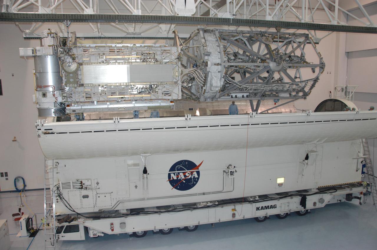
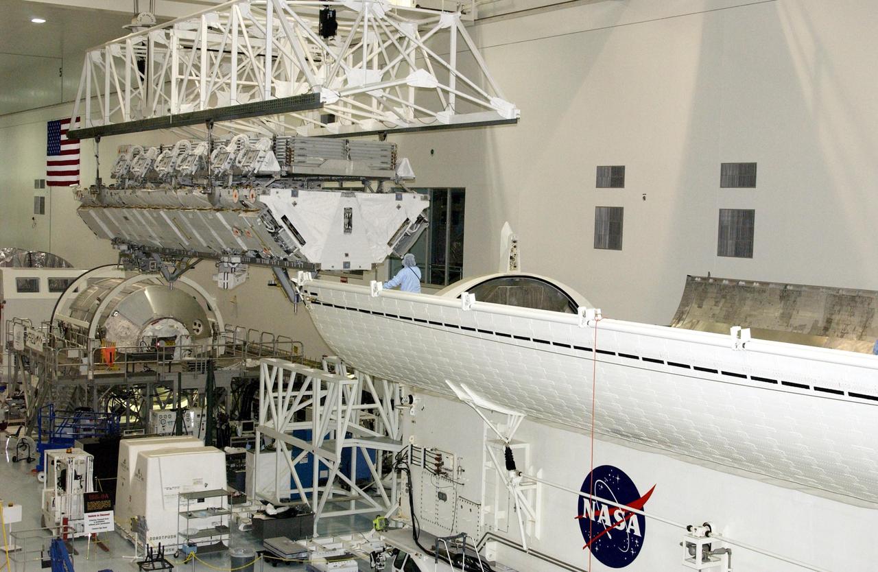
CAPE CANAVERAL, Fla. – In the Space Station Processing Facility at NASA's Kennedy Space Center in Florida, the integrated truss structure, S6, and solar arrays are lifted across the floor to install in the payload canister for transfer to Launch Pad 39A. The truss and arrays are space shuttle Discovery's payload for the STS-119 mission to the International Space Station. Launch of Discovery on the STS-119 mission is targeted for Feb. 12. During Discovery's 14-day mission, the crew will install the S6 truss segment and its solar arrays to the starboard side of the station, completing the station's truss, or backbone. Photo credit: NASA/Kevin Gill
CAPE CANAVERAL, Fla. – In the Space Station Processing Facility at NASA's Kennedy Space Center in Florida, the integrated truss structure, S6, and solar arrays are lifted across the floor to install in the payload canister for transfer to Launch Pad 39A. The truss and arrays are space shuttle Discovery's payload for the STS-119 mission to the International Space Station. Launch of Discovery on the STS-119 mission is targeted for Feb. 12. During Discovery's 14-day mission, the crew will install the S6 truss segment and its solar arrays to the starboard side of the station, completing the station's truss, or backbone. Photo credit: NASA/Kevin Gill
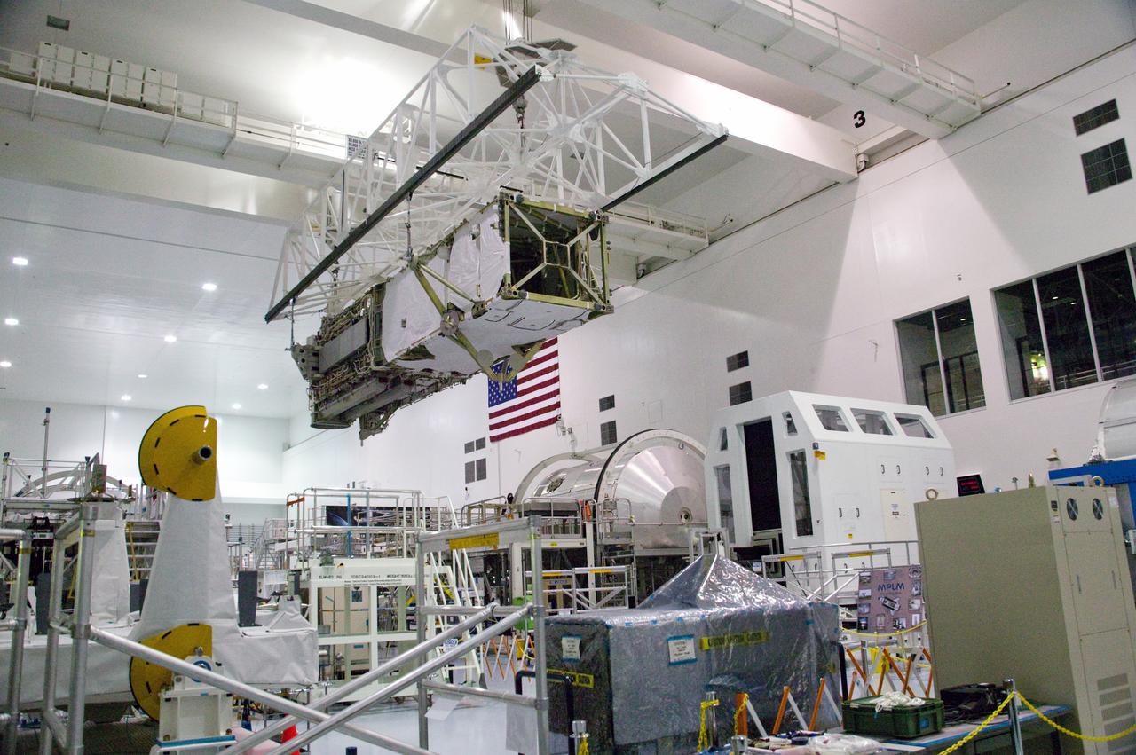
CAPE CANAVERAL, Fla. – In the Space Station Processing Facility at NASA's Kennedy Space Center in Florida, the integrated truss structure, S6, and solar arrays are lifted across the floor to install in the payload canister for transfer to Launch Pad 39A. The truss and arrays are space shuttle Discovery's payload for the STS-119 mission to the International Space Station. Launch of Discovery on the STS-119 mission is targeted for Feb. 12. During Discovery's 14-day mission, the crew will install the S6 truss segment and its solar arrays to the starboard side of the station, completing the station's truss, or backbone. Photo credit: NASA/Kevin Gill

CAPE CANAVERAL, Fla. – In the Space Station Processing Facility at NASA's Kennedy Space Center in Florida, the integrated truss structure, S6, and solar arrays are moved closer to the payload canister for installation and transfer to Launch Pad 39A. The truss and arrays are space shuttle Discovery's payload for the STS-119 mission to the International Space Station. Launch of Discovery on the STS-119 mission is targeted for Feb. 12. During Discovery's 14-day mission, the crew will install the S6 truss segment and its solar arrays to the starboard side of the station, completing the station's truss, or backbone. Photo credit: NASA/Kevin Gill
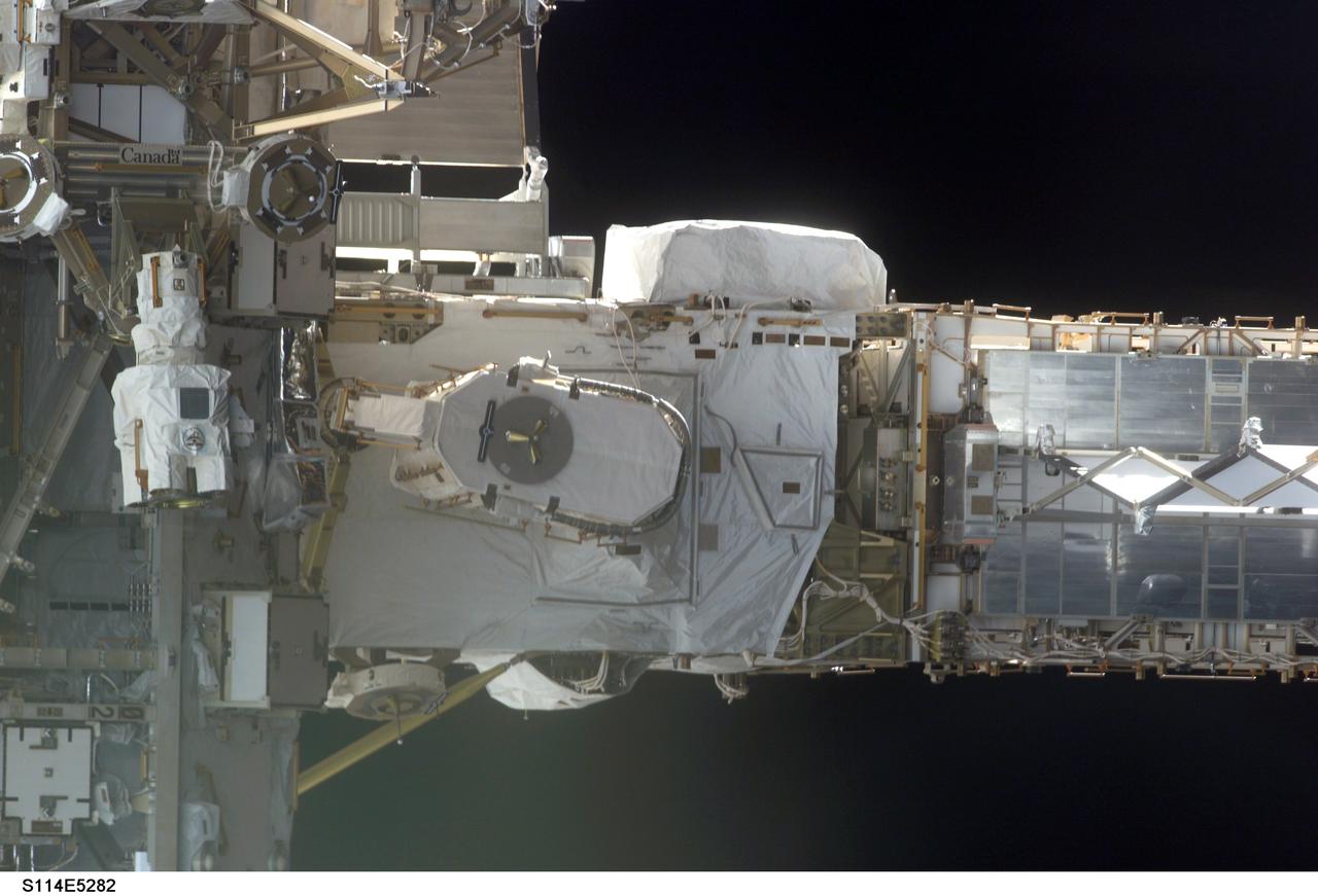
STS114-E-5282 (28 July 2005) --- This frame and STS114-E-5283 actually can be conjoined and rotated 90 degrees to make a single frame, providing an "astronaut's eye view" from Discovery's aft cabin looking toward the recently docked International Space Station. At the left side are the S0 truss and mobile transporter, with the P6 truss on the right side.

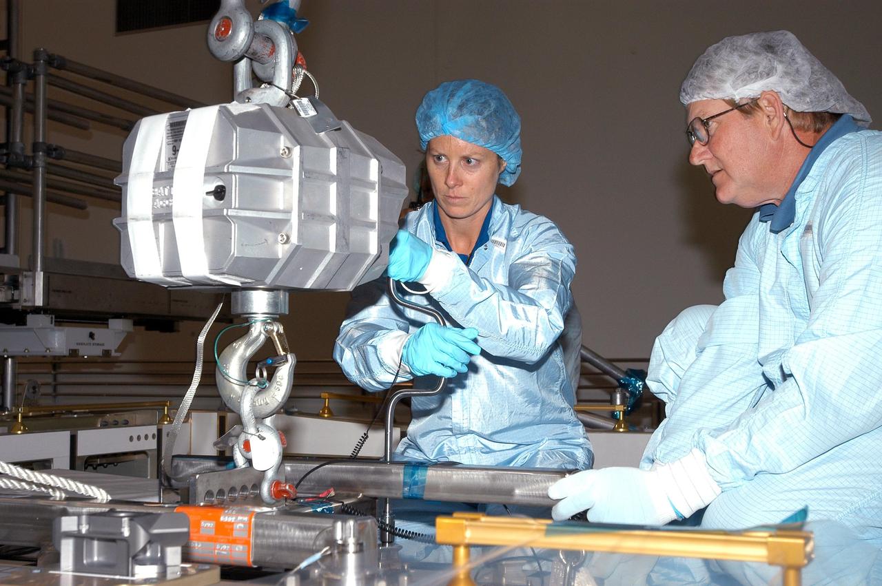
KENNEDY SPACE CENTER, FLA. - In the Space Station Processing Facility, astronaut Tracy Caldwell (left) assists a technician check out the Pump Flow Control Subsystem (PFCS) before it is installed on the upper deck of the S6 Truss. The PFCS pumps and controls the liquid ammonia used to cool the various Orbital Replacement Units on the Integrated Equipment Assembly that make up the S6 Photo-Voltaic Power Module on the International Space Station (ISS). The fourth starboard truss segment, the S6 Truss measures 112 feet long by 39 feet wide. The solar arrays are mounted on a “blanket” that can be folded like an accordion for delivery to the ISS. Once in orbit, astronauts will deploy the blankets to their full size. When completed, the Station's electrical power system (EPS) will use eight photovoltaic solar arrays to convert sunlight to electricity. Delivery of the S6 Truss, the last power module truss segment, is targeted for mission STS-119.
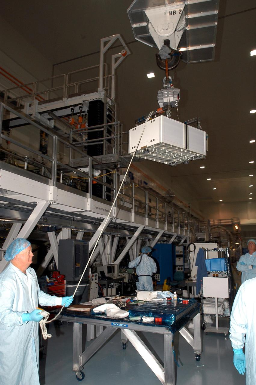
KENNEDY SPACE CENTER, FLA. - In the Space Station Processing Facility, a technician steadies the Pump Flow Control Subsystem (PFCS) as it is lifted and moved toward the S6 Truss. The PFCS pumps and controls the liquid ammonia used to cool the various Orbital Replacement Units on the Integrated Equipment Assembly that make up the S6 Photo-Voltaic Power Module on the International Space Station (ISS). The fourth starboard truss segment, the S6 Truss measures 112 feet long by 39 feet wide. Its solar arrays are mounted on a “blanket” that can be folded like an accordion for delivery to the ISS. Once in orbit, astronauts will deploy the blankets to their full size. When completed, the Station's electrical power system (EPS) will use eight photovoltaic solar arrays to convert sunlight to electricity. Delivery of the S6 Truss, the last power module truss segment, is targeted for mission STS-119.
KENNEDY SPACE CENTER, FLA. - In the Space Station Processing Facility, astronaut Tracy Caldwell (left) assists technicians install the Pump Flow Control Subsystem (PFCS) onto the upper deck of the S6 Truss. The PFCS pumps and controls the liquid ammonia used to cool the various Orbital Replacement Units on the Integrated Equipment Assembly that make up the S6 Photo-Voltaic Power Module on the International Space Station (ISS). The fourth starboard truss segment, the S6 Truss measures 112 feet long by 39 feet wide. Its solar arrays are mounted on a “blanket” that can be folded like an accordion for delivery to the ISS. Once in orbit, astronauts will deploy the blankets to their full size. When completed, the Station's electrical power system (EPS) will use eight photovoltaic solar arrays to convert sunlight to electricity. Delivery of the S6 Truss, the last power module truss segment, is targeted for mission STS-119.
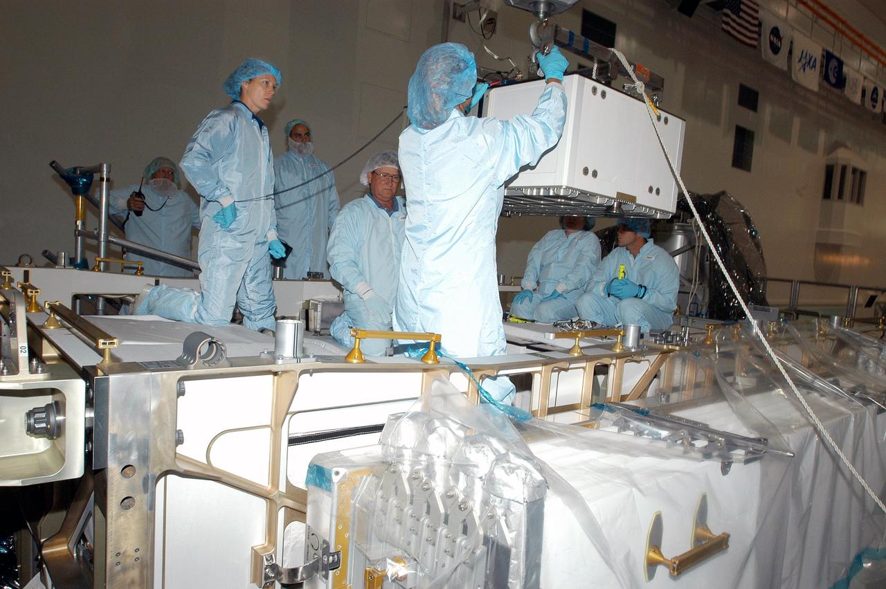
KENNEDY SPACE CENTER, FLA. - In the Space Station Processing Facility, astronaut Tracy Caldwell (second from left) assists technicians position the Pump Flow Control Subsystem (PFCS) over the upper deck of the S6 Truss. The PFCS pumps and controls the liquid ammonia used to cool the various Orbital Replacement Units on the Integrated Equipment Assembly that make up the S6 Photo-Voltaic Power Module on the International Space Station (ISS). The fourth starboard truss segment, the S6 Truss measures 112 feet long by 39 feet wide. Its solar arrays are mounted on a “blanket” that can be folded like an accordion for delivery to the ISS. Once in orbit, astronauts will deploy the blankets to their full size. When completed, the Station's electrical power system (EPS) will use eight photovoltaic solar arrays to convert sunlight to electricity. Delivery of the S6 Truss, the last power module truss segment, is targeted for mission STS-119.

KENNEDY SPACE CENTER, FLA. - In the Space Station Processing Facility, astronaut Tracy Caldwell (second from left) assists technicians lower the Pump Flow Control Subsystem (PFCS) into position onto the upper deck of the S6 Truss. The PFCS pumps and controls the liquid ammonia used to cool the various Orbital Replacement Units on the Integrated Equipment Assembly that make up the S6 Photo-Voltaic Power Module on the International Space Station (ISS). The fourth starboard truss segment, the S6 Truss measures 112 feet long by 39 feet wide. Its solar arrays are mounted on a “blanket” that can be folded like an accordion for delivery to the ISS. Once in orbit, astronauts will deploy the blankets to their full size. When completed, the Station's electrical power system (EPS) will use eight photovoltaic solar arrays to convert sunlight to electricity. Delivery of the S6 Truss, the last power module truss segment, is targeted for mission STS-119.
CAPE CANAVERAL, Fla. – In the Space Station Processing Facility at NASA's Kennedy Space Center in Florida, the integrated truss structure, S6, and solar arrays are lowered into the payload canister for transfer to Launch Pad 39A. Launch of Discovery on the STS-119 mission is targeted for Feb. 12. During Discovery's 14-day mission, the crew will install the S6 truss segment and its solar arrays to the starboard side of the station, completing the station's truss, or backbone. Photo credit: NASA/Kevin Gill
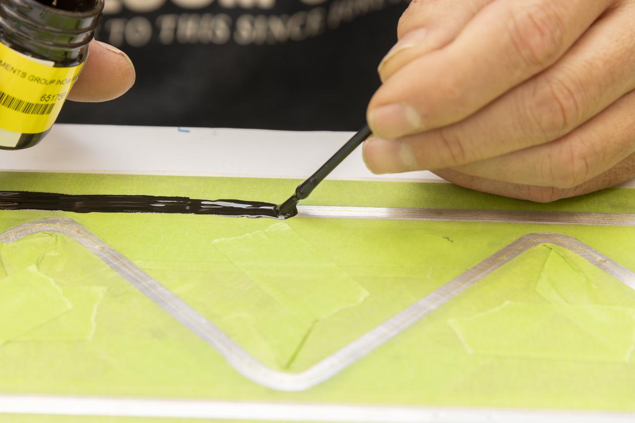
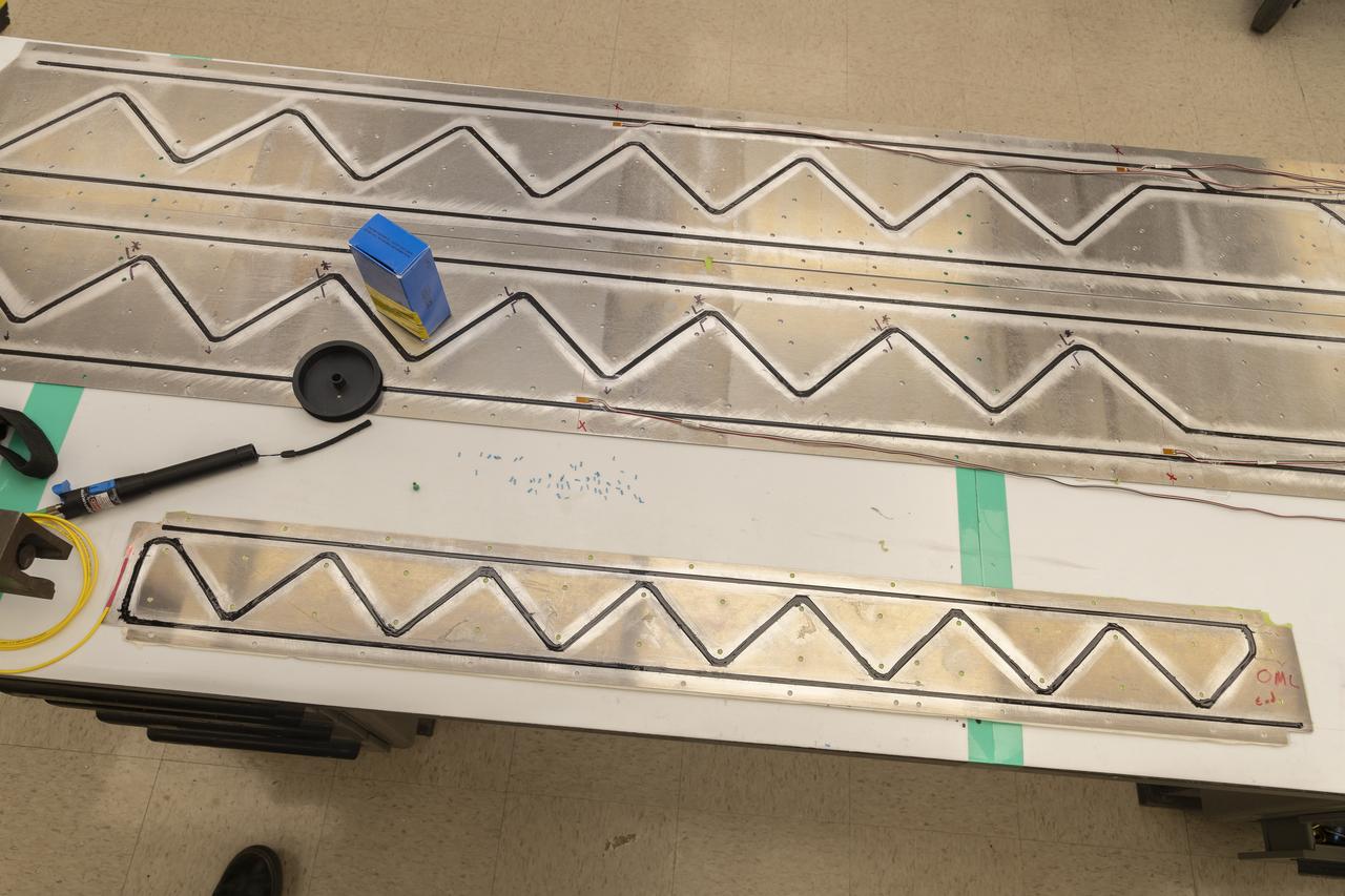
An epoxy is applied to adhere the fiber optic sensor installation on the Mock Truss-Braced Wing 10-foot model at NASA’s Armstrong Flight Research Center in Edwards, California.
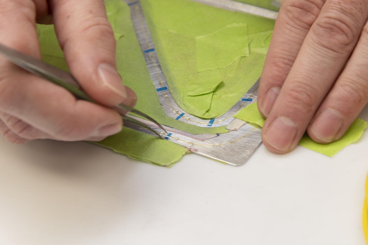
Engineering technician Jeff Howell removes thin pieces of tape from fiber used for a bonding process on the Mock Truss-Braced Wing 10-foot model at NASA’s Armstrong Flight Research Center in Edwards, California.
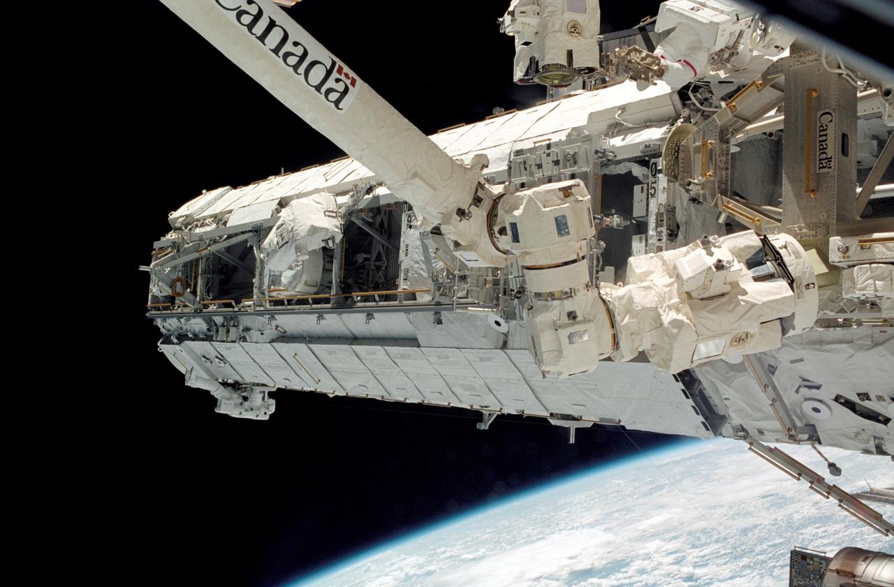
Launched October 7, 2002 aboard the Space Shuttle Orbiter Atlantis, the STS-112 mission lasted 11 days and performed three sessions of Extra Vehicular Activity (EVA). Its primary mission was to install the Starboard (S1) Integrated Truss Structure and Equipment Translation Aid (CETA) Cart to the International Space Station (ISS). The S1 truss provides structural support for the orbiting research facility's radiator panels, which use ammonia to cool the Station's complex power system. The S1 truss, attached to the S0 (S Zero) truss installed by the previous STS-110 mission, flows 637 pounds of anhydrous ammonia through three heat rejection radiators. The truss is 45-feet long, 15-feet wide, 10-feet tall, and weighs approximately 32,000 pounds. The CETA is the first of two human-powered carts that will ride along the International Space Station's railway providing a mobile work platform for future extravehicular activities by astronauts. This is a view of the newly installed S1 Truss as photographed during the mission's first scheduled EVA. The Station's Canadarm2 is in the foreground. Visible are astronauts Piers J. Sellers (lower left) and David A. Wolf (upper right), both STS-112 mission specialists.
In the Space Station Processing Facility at NASA's Kennedy Space Center, workers prepare to connect cables that will recharge the battery for the S6 integrated truss. The final starboard truss in the assembly of the International Space Station, the S6 is scheduled to fly on space shuttle mission STS-119, whose launch date is not yet determined.
In the Space Station Processing Facility at NASA's Kennedy Space Center, a worker connects a cable to recharge the battery for the S6 integrated truss. The final starboard truss in the assembly of the International Space Station, the S6 is scheduled to fly on space shuttle mission STS-119, whose launch date is not yet determined.
In the Space Station Processing Facility at NASA's Kennedy Space Center, a worker holds a cable that will help recharge the battery for the S6 integrated truss. The final starboard truss in the assembly of the International Space Station, the S6 is scheduled to fly on space shuttle mission STS-119, whose launch date is not yet determined.
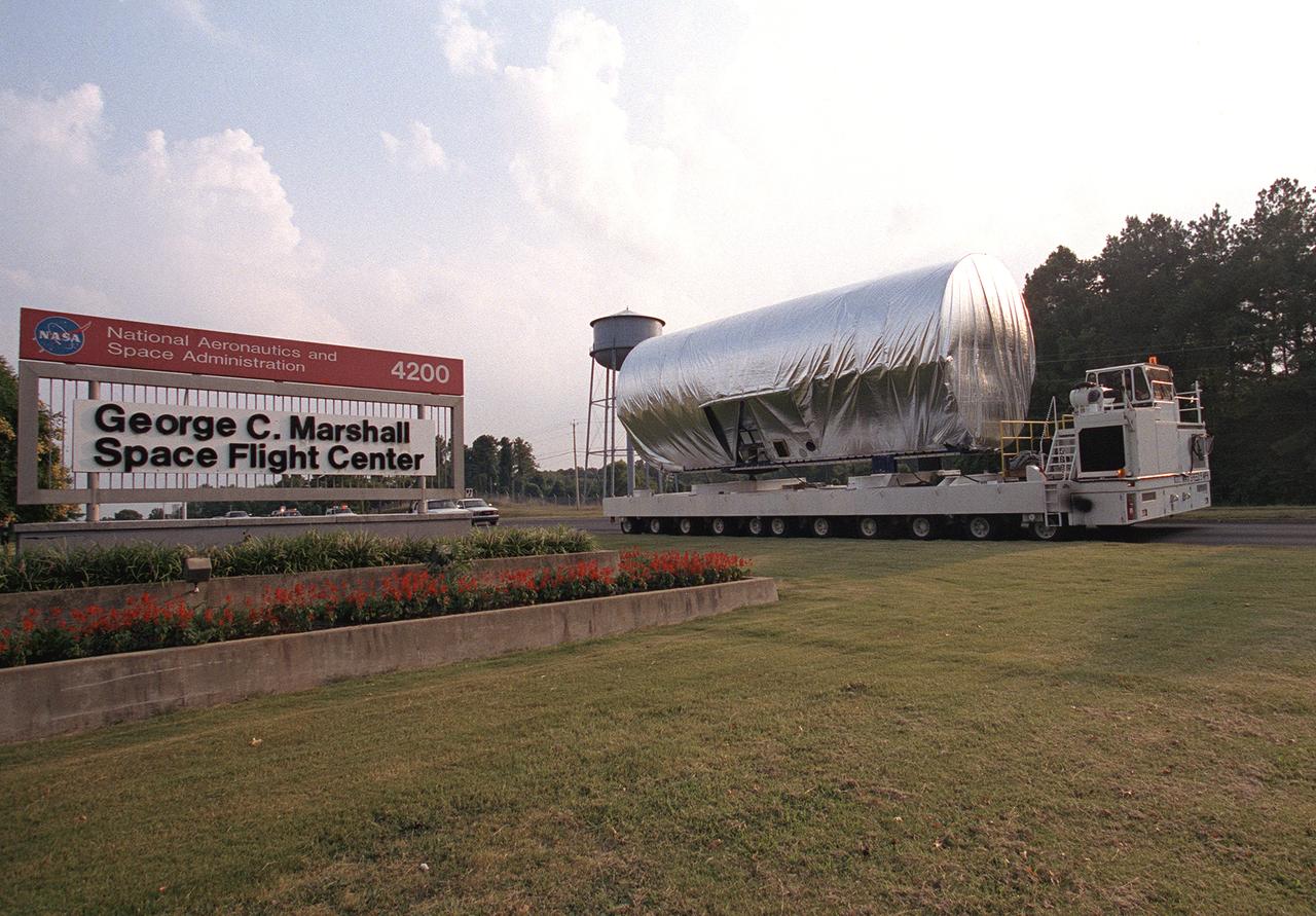
The 45-foot, port-side (P1) truss segment flight article for the International Space Station is being transported to the Redstone Airfield, Marshall Space Flight Center. The truss will be loaded aboard NASA's Super Guppy cargo plane for shipment to the Kennedy Space Center.
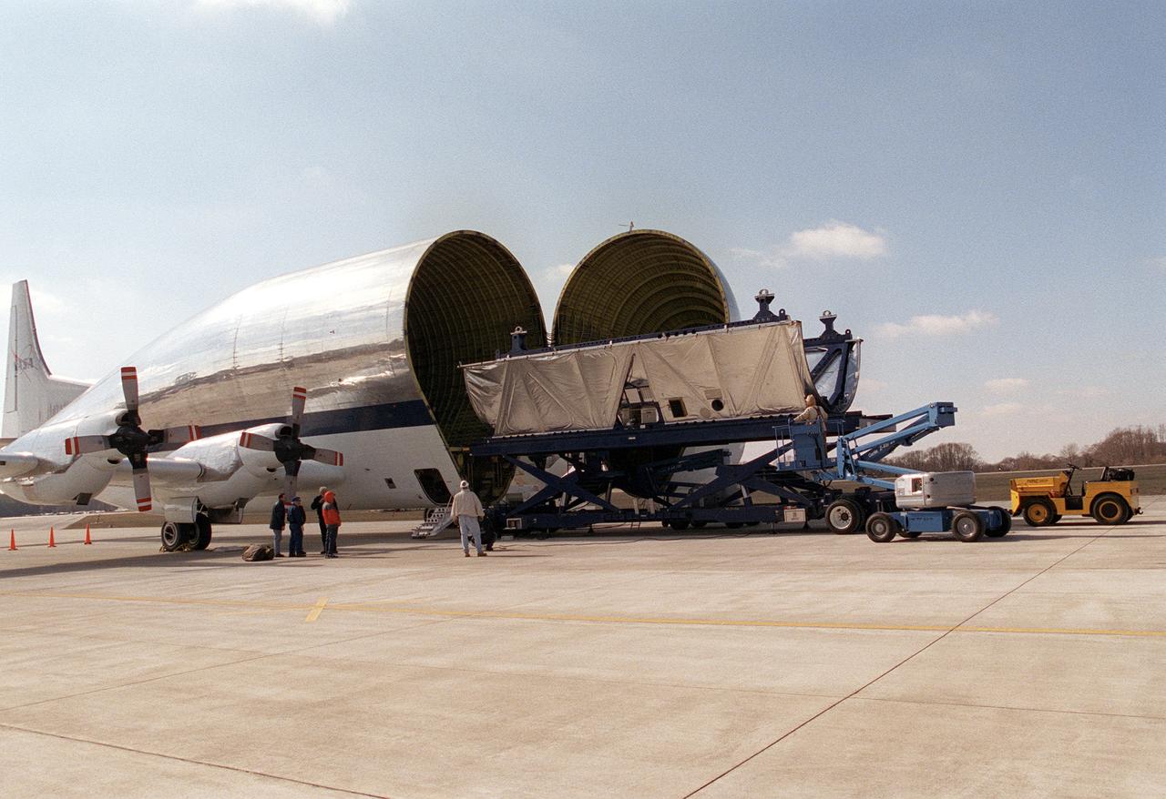
A section of the International Space Station truss assembly arrived at the Marshall Space Flight Center on NASA's Super Guppy cargo plane for structural and design testing as well as installation of critical flight hardware.
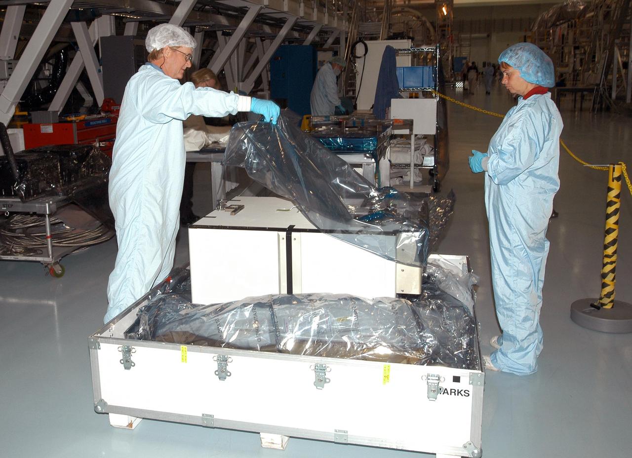
KENNEDY SPACE CENTER, FLA. - Unpacking of the Pump Flow Control Subsystem (PFCS) begins in the Space Station Processing Facility. The PFCS pumps and controls the liquid ammonia used to cool the various Orbital Replacement Units on the Integrated Equipment Assembly that make up the S6 Photo-Voltaic Power Module on the International Space Station (ISS). The fourth starboard truss segment, the S6 Truss measures 112 feet long by 39 feet wide. Its solar arrays are mounted on a “blanket” that can be folded like an accordion for delivery to the ISS. Once in orbit, astronauts will deploy the blankets to their full size. When completed, the Station's electrical power system will use eight photovoltaic solar arrays to convert sunlight to electricity. Delivery of the S6 Truss, the last power module truss segment, is targeted for mission STS-119.
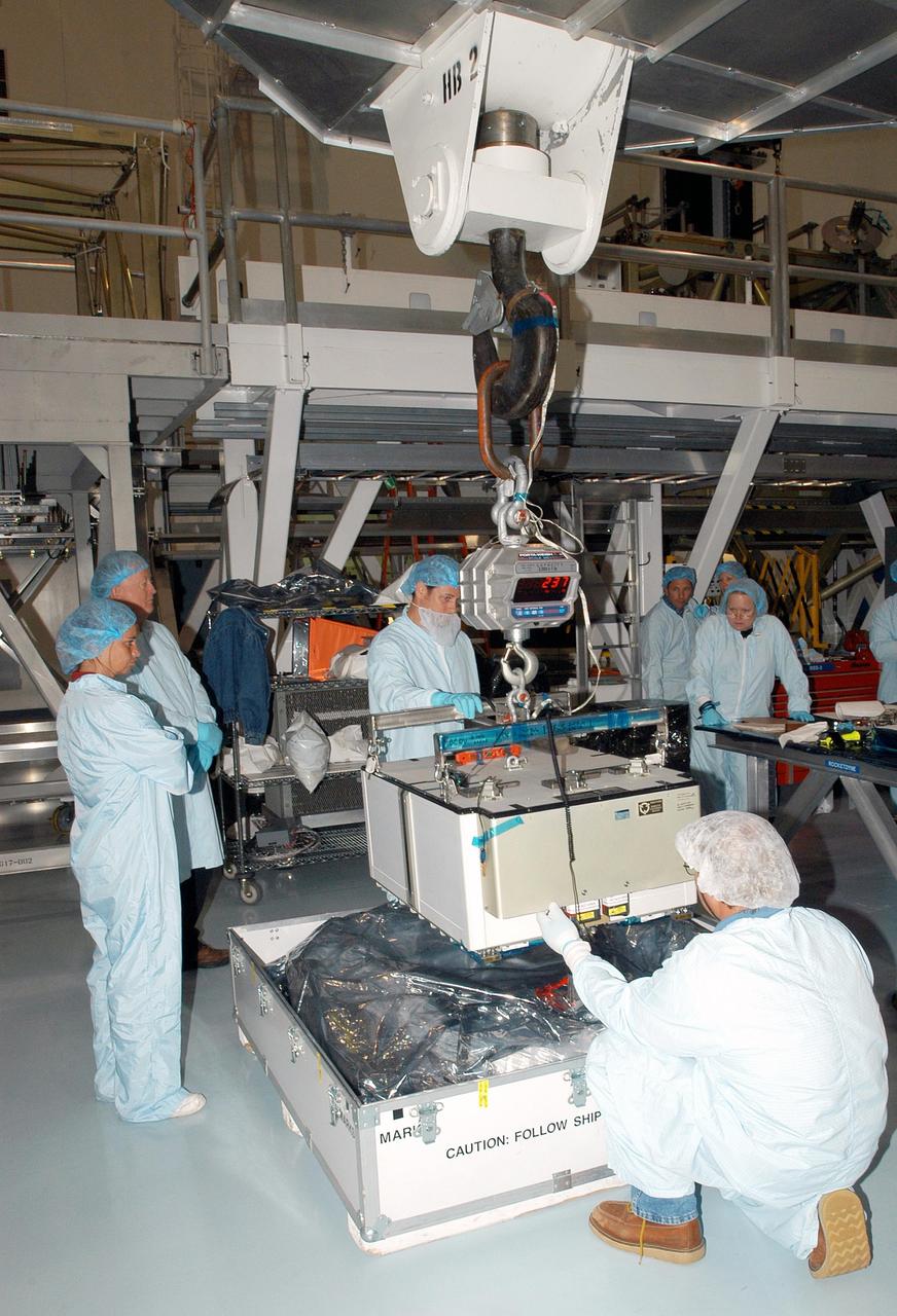
KENNEDY SPACE CENTER, FLA. - Technicians attach a crane to the Pump Flow Control Subsystem (PFCS) in the Space Station Processing Facility. The PFCS pumps and controls the liquid ammonia used to cool the various Orbital Replacement Units on the Integrated Equipment Assembly that make up the S6 Photo-Voltaic Power Module on the International Space Station (ISS). The fourth starboard truss segment, the S6 Truss measures 112 feet long by 39 feet wide. Its solar arrays are mounted on a “blanket” that can be folded like an accordion for delivery to the ISS. Once in orbit, astronauts will deploy the blankets to their full size. When completed, the Station's electrical power system (EPS) will use eight photovoltaic solar arrays to convert sunlight to electricity. Delivery of the S6 Truss, the last power module truss segment, is targeted for mission STS-119.
KENNEDY SPACE CENTER, FLA. -- STS-113 Commander James Wetherbee finishes suiting up before leaving for Launch Pad 39A. Wetherbee will be making his sixth Shuttle flight. The primary mission for the crew is bringing the Expedition 6 crew to the Station and returning the Expedition 5 crew to Earth. The major objective of the mission is delivery of the Port 1 (P1) Integrated Truss Assembly, which will be attached to the port side of the S0 truss. Three spacewalks are planned to install and activate the truss and its associated equipment. Launch of Space Shuttle Endeavour on mission STS-113 is scheduled for 8:15 p.m. EST.
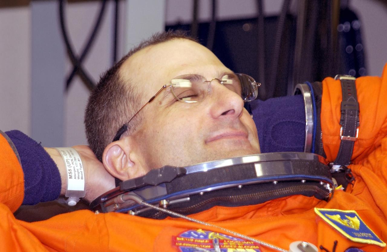
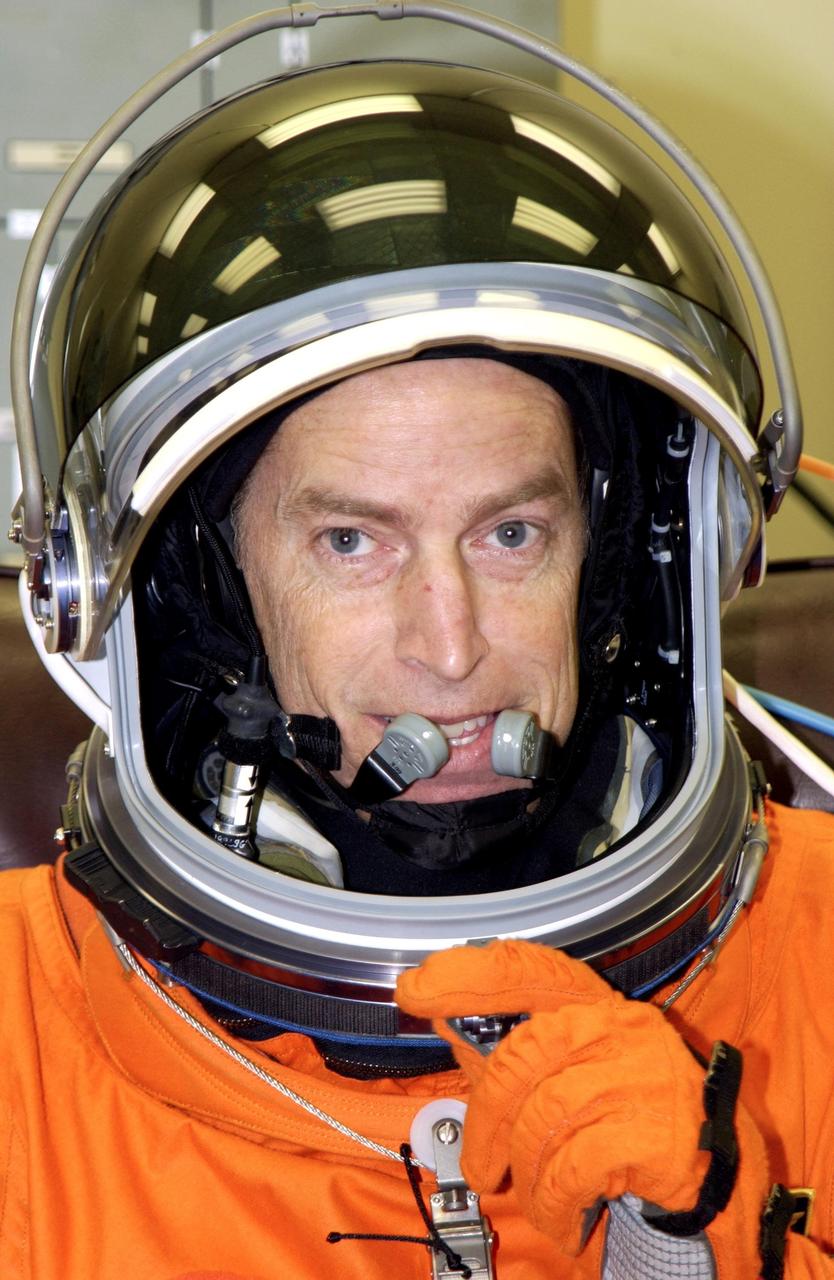
KENNEDY SPACE CENTER, FLA. -- Expedition 6 flight engineer Donald Pettit relaxes during suitup for launch. Pettit will be making his first Shuttle flight. The primary mission for the crew is bringing the Expedition 6 crew to the Station and returning the Expedition 5 crew to Earth. The major objective of the mission is delivery of the Port 1 (P1) Integrated Truss Assembly, which will be attached to the port side of the S0 truss. Three spacewalks are planned to install and activate the truss and its associated equipment. Launch of Space Shuttle Endeavour on mission STS-113 is scheduled for 8:15 p.m. EST.
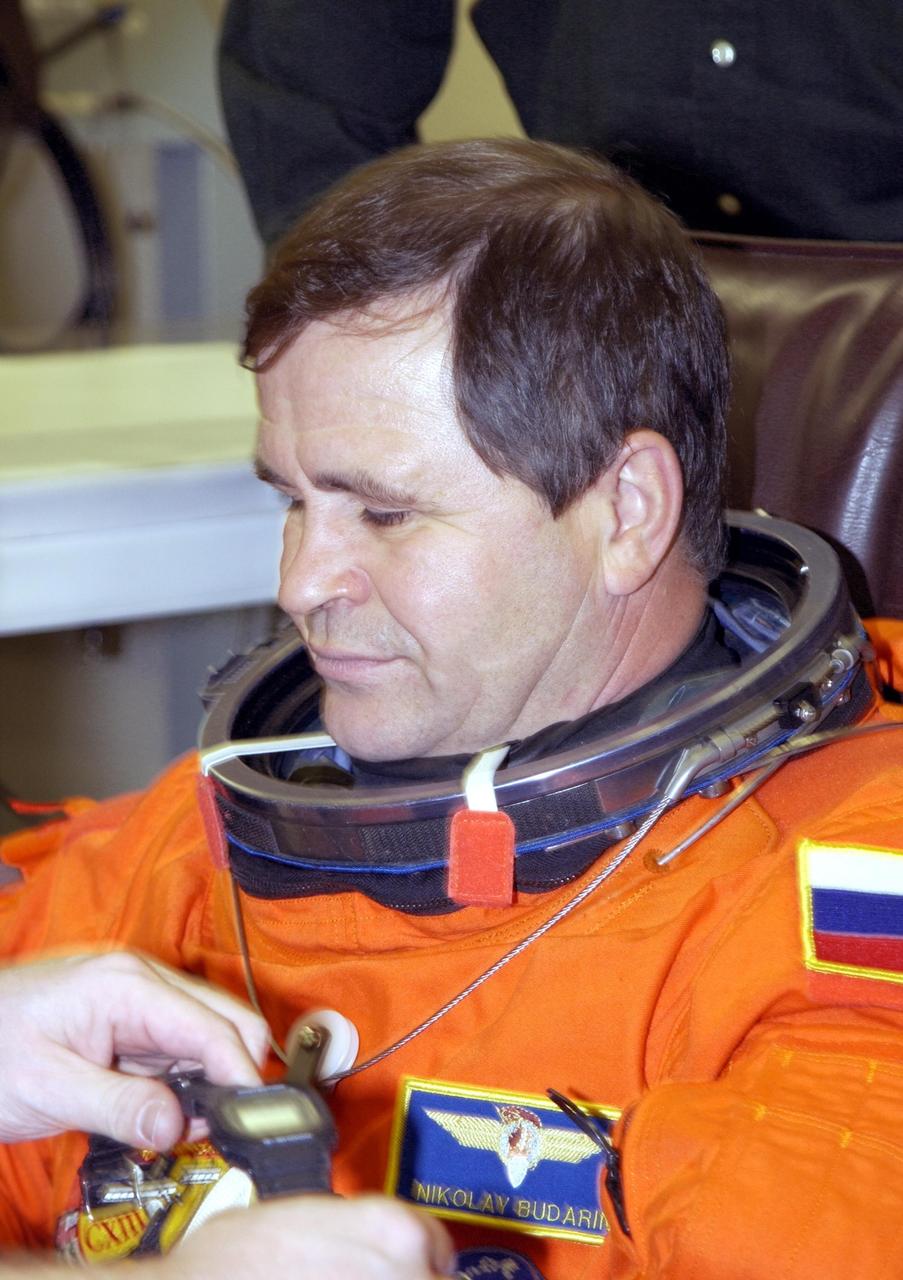
KENNEDY SPACE CENTER, FLA. - Expedition 6 flight engineer Nikolai Budarin relaxes during suitup for launch. Budarin, who is with the Russian Space Agency, will be making his second Shuttle flight. The primary mission for the crew is bringing the Expedition 6 crew to the Station and returning the Expedition 5 crew to Earth. The major objective of the mission is delivery of the Port 1 (P1) Integrated Truss Assembly, which will be attached to the port side of the S0 truss. Three spacewalks are planned to install and activate the truss and its associated equipment. Launch of Space Shuttle Endeavour on mission STS-113 is scheduled for 8:15 p.m. EST.
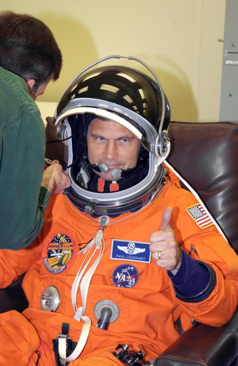
KENNEDY SPACE CENTER, FLA. -- STS-113 Pilot Paul Lockhart shows thumbs up for launch as he finishes suiting up. Lockhart will be making his second Shuttle flight. The primary mission for the crew is bringing the Expedition 6 crew to the Station and returning the Expedition 5 crew to Earth. The major objective of the mission is delivery of the Port 1 (P1) Integrated Truss Assembly, which will be attached to the port side of the S0 truss. Three spacewalks are planned to install and activate the truss and its associated equipment. Launch of Space Shuttle Endeavour on mission STS-113 is scheduled for 8:15 p.m. EST.
Shown here is the International Space Station (ISS) S1 Truss in preparation for installation in the payload bay of the Space Shuttle Atlantis at NASA's Kennedy Space Center )KSC)in Florida. The truss launched October 7, 2002 on the STS-112 mission and will be attached during three spacewalks. Constructed primarily of aluminum, it measures 45 feet long, 15 feet wide, 10 feet tall, and weighs over 27,000 pounds. It is one of nine similar truss segments that, combined, will serve as the Station's main backbone, measuring 356 feet from end to end upon completion. Manufactured by the Boeing Company in Huntington Beach, California, the truss was flown to the Marshall Space Flight Center, in Huntsville, Alabama where brackets, cable trays, fluid tubing, and other secondary components and outfitting items were added. In Huntsville, it was screened for manufacturing flaws, including pressure and leak checking tubing, and electrical checks for cabling, before being shipped to KSC for final hardware installation and testing. The Space Station's labs, living modules, solar arrays, heat radiators, and other main components will be attached to the truss.
Launched October 7, 2002 aboard the Space Shuttle Orbiter Atlantis, the STS-112 mission lasted 11 days and performed three sessions of Extra Vehicular Activity (EVA). Its primary mission was to install the Starboard Side Integrated Truss Structure (S1) and Equipment Translation Aid (CETA) Cart to the International Space Station (ISS). The S1 truss provides structural support for the orbiting research facility's radiator panels, which use ammonia to cool the Station's complex power system. The S1 truss, attached to the S0 (S Zero) truss installed by the previous STS-110 mission, flows 637 pounds of anhydrous ammonia through three heat rejection radiators. The truss is 45-feet long, 15-feet wide, 10-feet tall, and weighs approximately 32,000 pounds. The CETA is the first of two human-powered carts that will ride along the International Space Station's railway providing a mobile work platform for future extravehicular activities by astronauts. In this photograph, Astronaut Piers J. Sellers uses both a handrail on the Destiny Laboratory and a foot restraint on the Space Station Remote Manipulator System or Canadarm2 to remain stationary while performing work at the end of the STS-112 mission's second space walk. A cloud-covered Earth provides the backdrop for the scene.

Engineering technician Jeff Howell mounts conventional strain gauges to the Mock Truss-Braced Wing 10-foot model at NASA’s Armstrong Flight Research Center in Edwards, California. The conventional system data will be compared the Fiber Optic Sensing System developed at the center on the same wing to see how well the testing methods match.
Engineering technician Jeff Howell removes tape from the Mock Truss-Braced Wing 10-foot model at NASA’s Armstrong Flight Research Center in Edwards, California. The tape was used to limit the amount of epoxy on the model wing during the process to secure the fiber optic strain sensors to the wing.
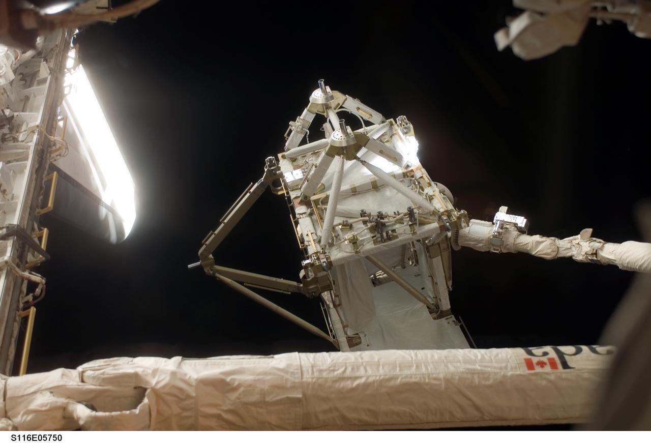
S116-E-05750 (11 Dec. 2006) --- The International Space Station's new P5 truss section is moved out of Space Shuttle Discovery's payload bay by a cabin-bound STS-116 crewmember, using the shuttle's Remote Manipulator System (RMS) robotic arm. The truss section will be handed to the station's Canadarm2 and will remain suspended over Discovery's port wing overnight, awaiting installation in the first of three planned spacewalks on Dec. 12.
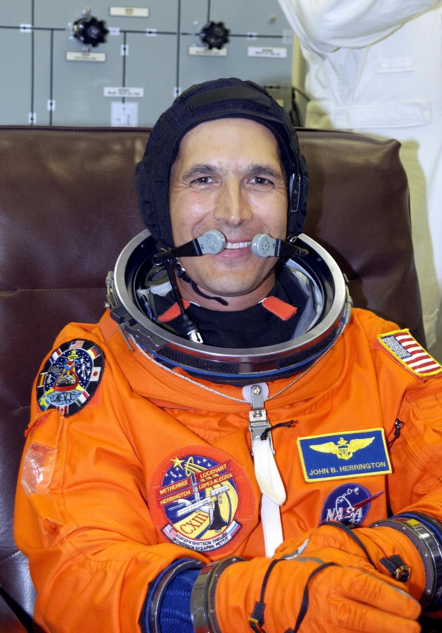
KENNEDY SPACE CENTER, FLA. -- STS-113 Mission Specialist John Herrington suits up for launch. Herrington will be making his first Shuttle flight. This is also the first launch of the first tribally enrolled Native American astronaut -- John B. Herrington -- on Space Transportation System. The primary mission for the crew is bringing the Expedition 6 crew to the Station and returning the Expedition 5 crew to Earth. The major objective of the mission is delivery of the Port 1 (P1) Integrated Truss Assembly, which will be attached to the port side of the S0 truss. Three spacewalks are planned to install and activate the truss and its associated equipment. Launch of Space Shuttle Endeavour on mission STS-113 is scheduled for 8:15 p.m. EST.
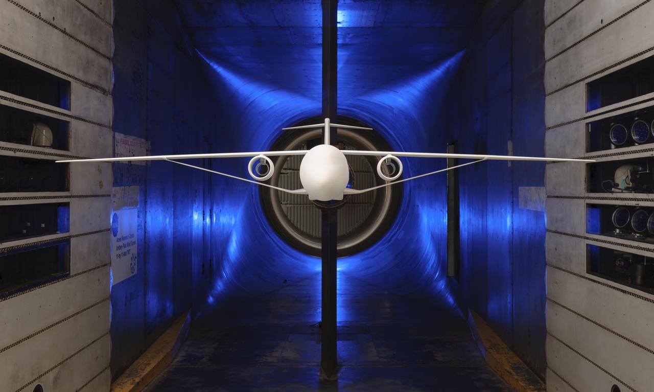
Truss-Braced Wind Model installed in the Ames 11x11 Foot Wind Tunnel for testing. The Truss-Braced model is part of the Subsonic Ultra Green Aircraft Research Project (SUGAR)
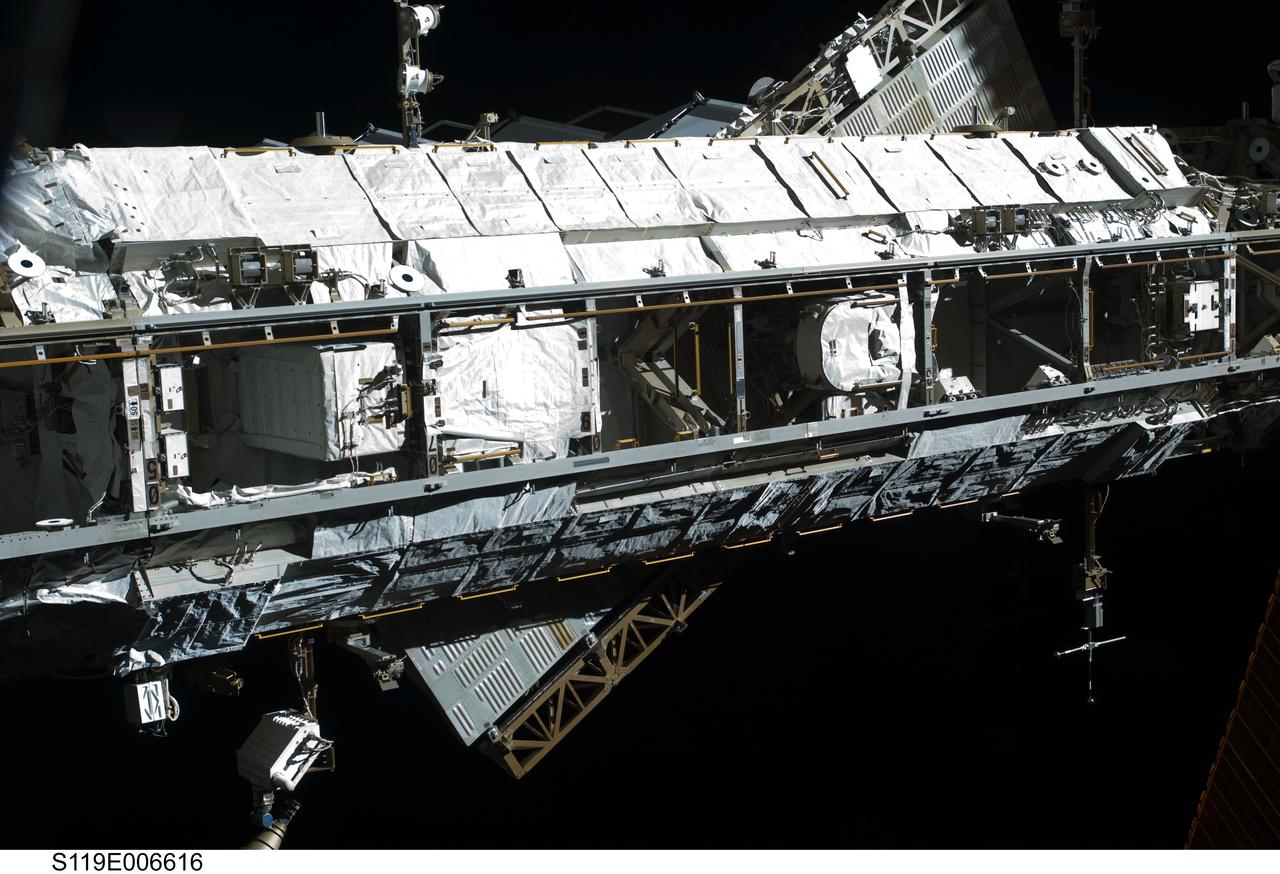
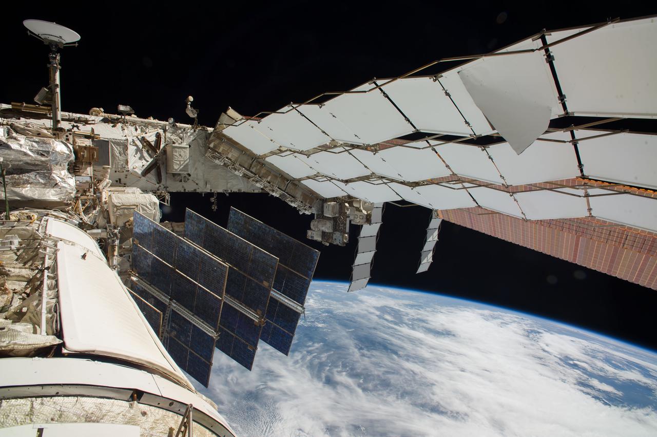
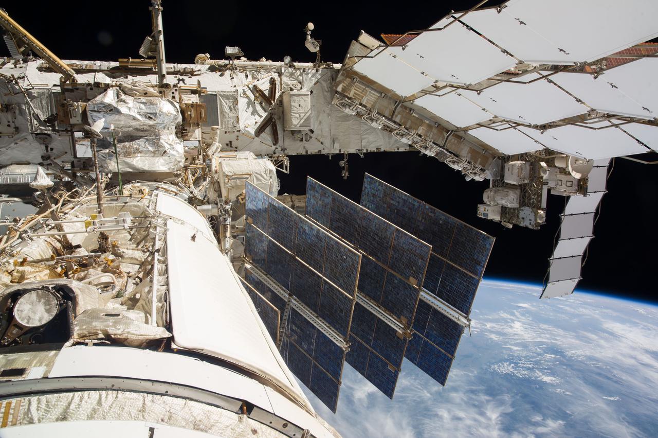
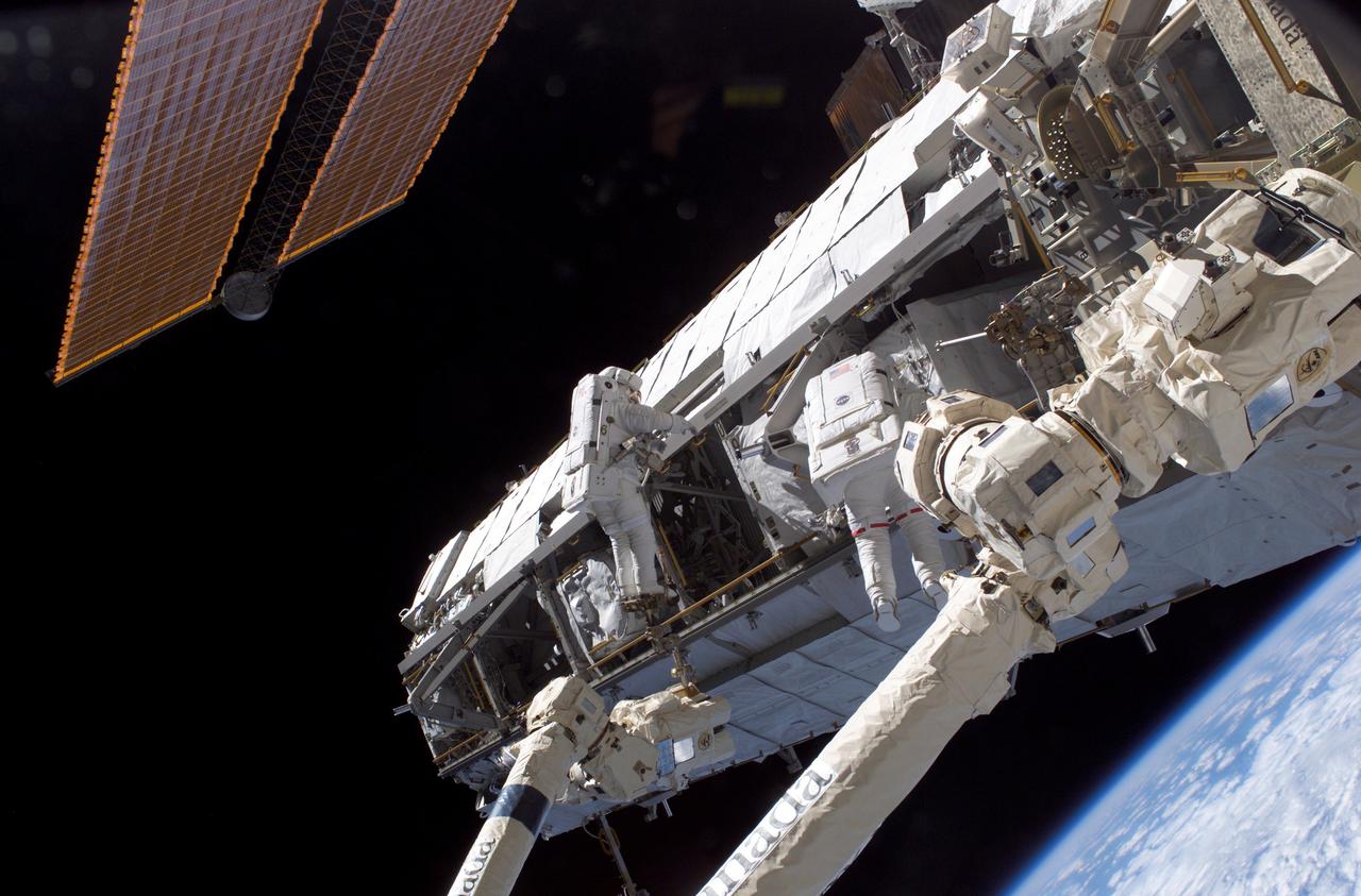
S119-E-006616 (18 March 2009) --- The International Space Station’s starboard truss is featured in this image photographed by a STS-119 crewmember while Space Shuttle Discovery is docked with the station.
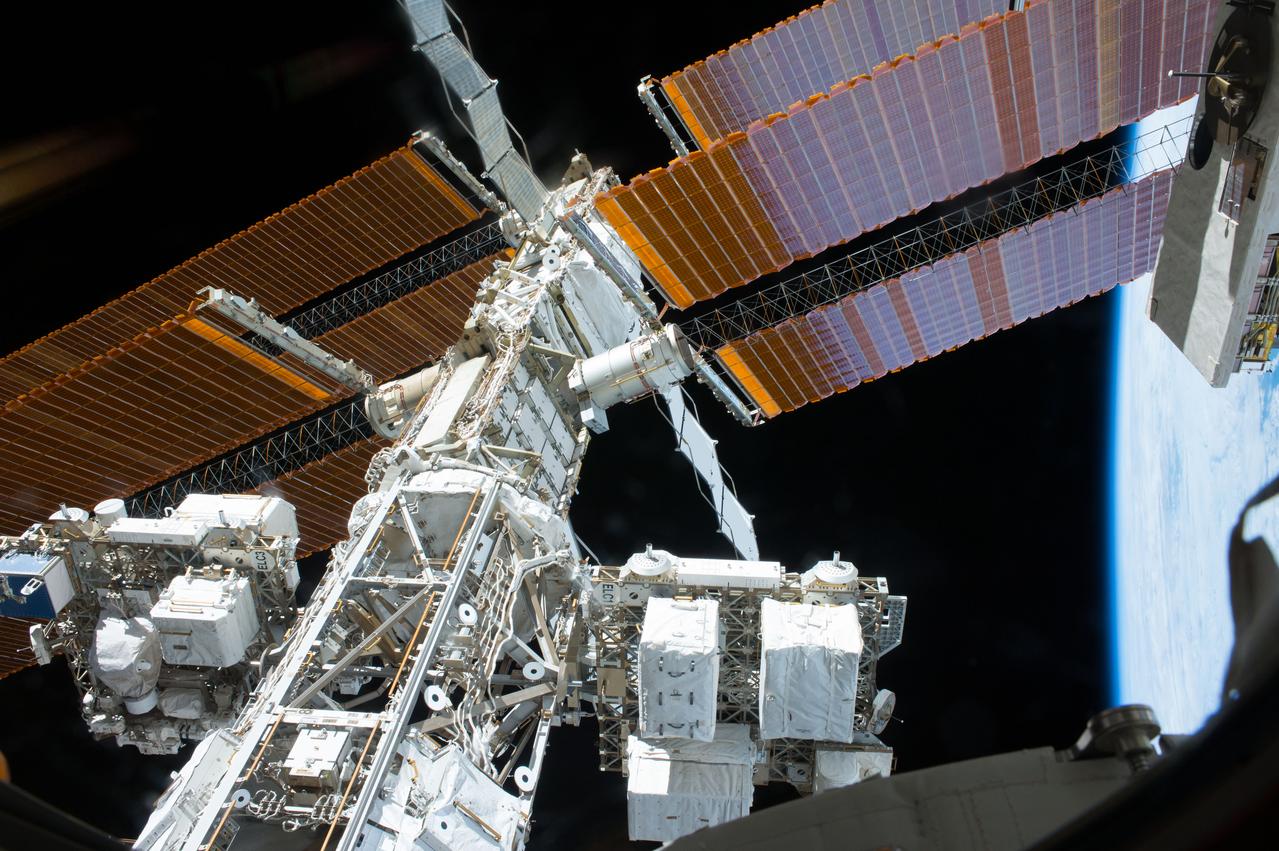
View of the ISS port Truss segments taken through a window in the Kibo Japanese Experiment Pressurized Module (JPM). ExPRESS (Expedite the Processing of Experiments to Space Station) Logistics Carrier-3 (ELC-3) and ELC-1 are in view.
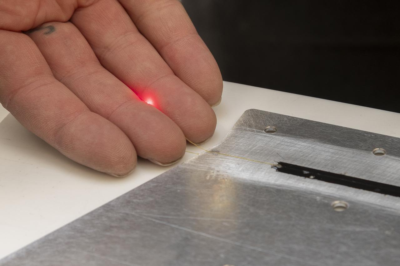
A red light confirms that the fiber of the Fiber Optic Sensing System installed on the Mock Truss-Braced Wing 10-foot model works as intended at NASA’s Armstrong Flight Research Center in Edwards, California. The fiber, which is about the thickness of a human hair, is part of a system that can provide strain information researchers can use to determine the model’s durability.
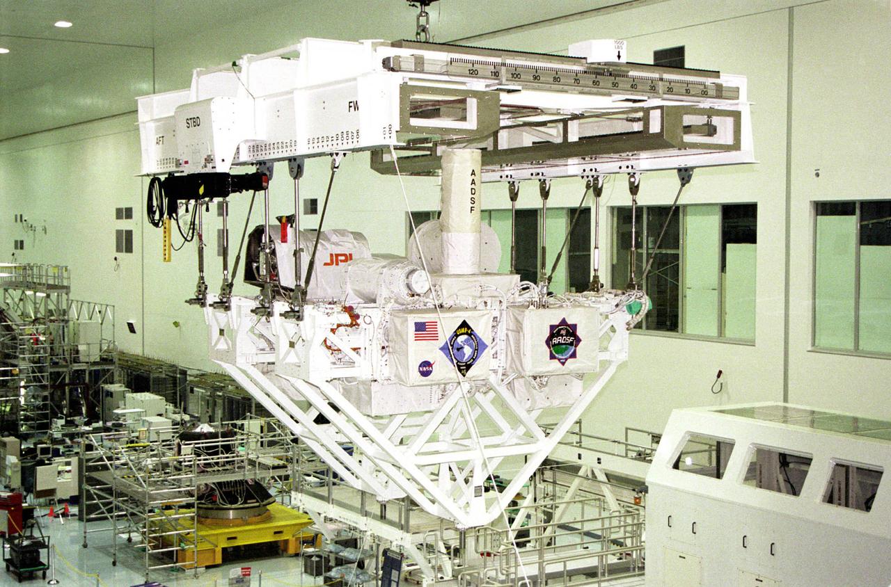
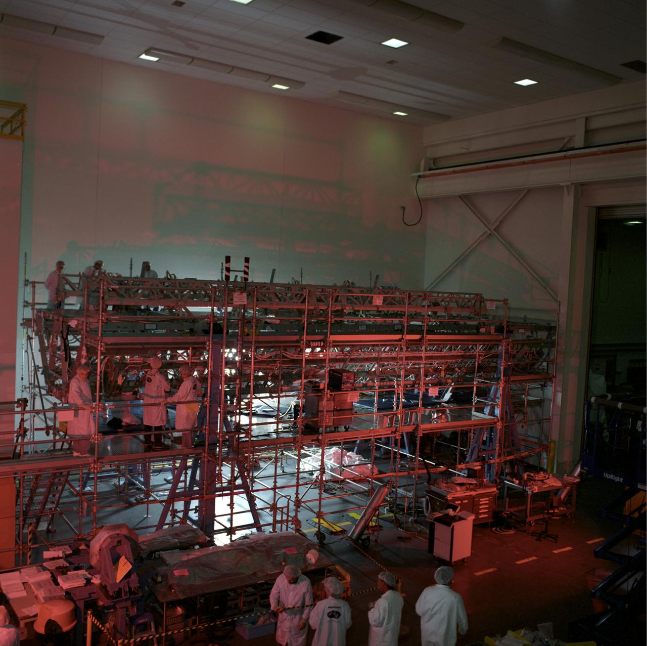
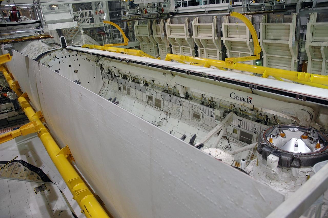
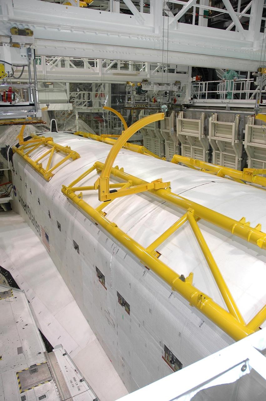
The USMP mission series pioneered sophisticated telescience technology to control experiments in the open cargo bay of the space shuttle. At Kennedy Space Center, the system of trusses that supported the USMP-4 experiments was loaded into the cargo bay. The bay doors were closed during launch but were opened in orbit.
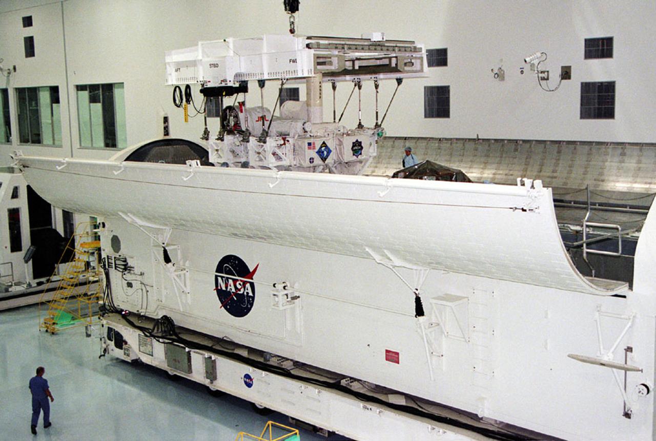
The USMP mission series pioneered sophisticated telescience technology to control experiments in the open cargo bay of the space shuttle. At Kennedy Space Center, the system of trusses that supported the USMP-4 experiments was loaded into the cargo bay. The bay doors were closed during launch but were opened in orbit.
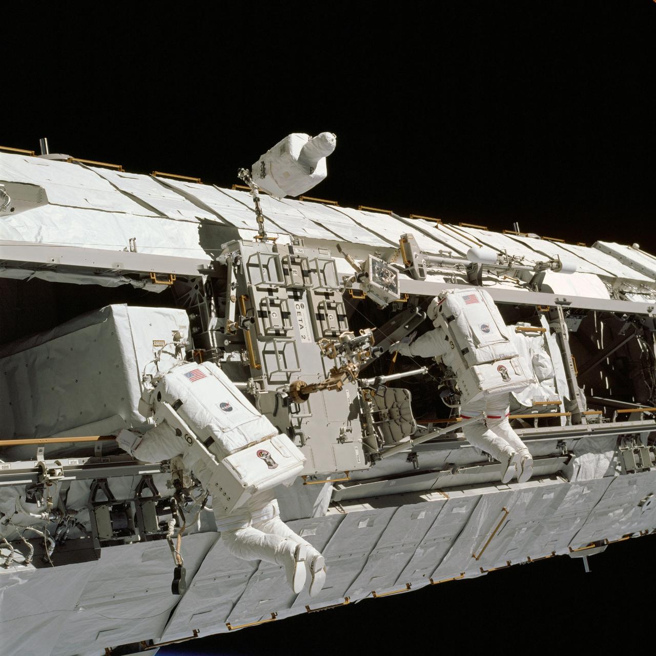
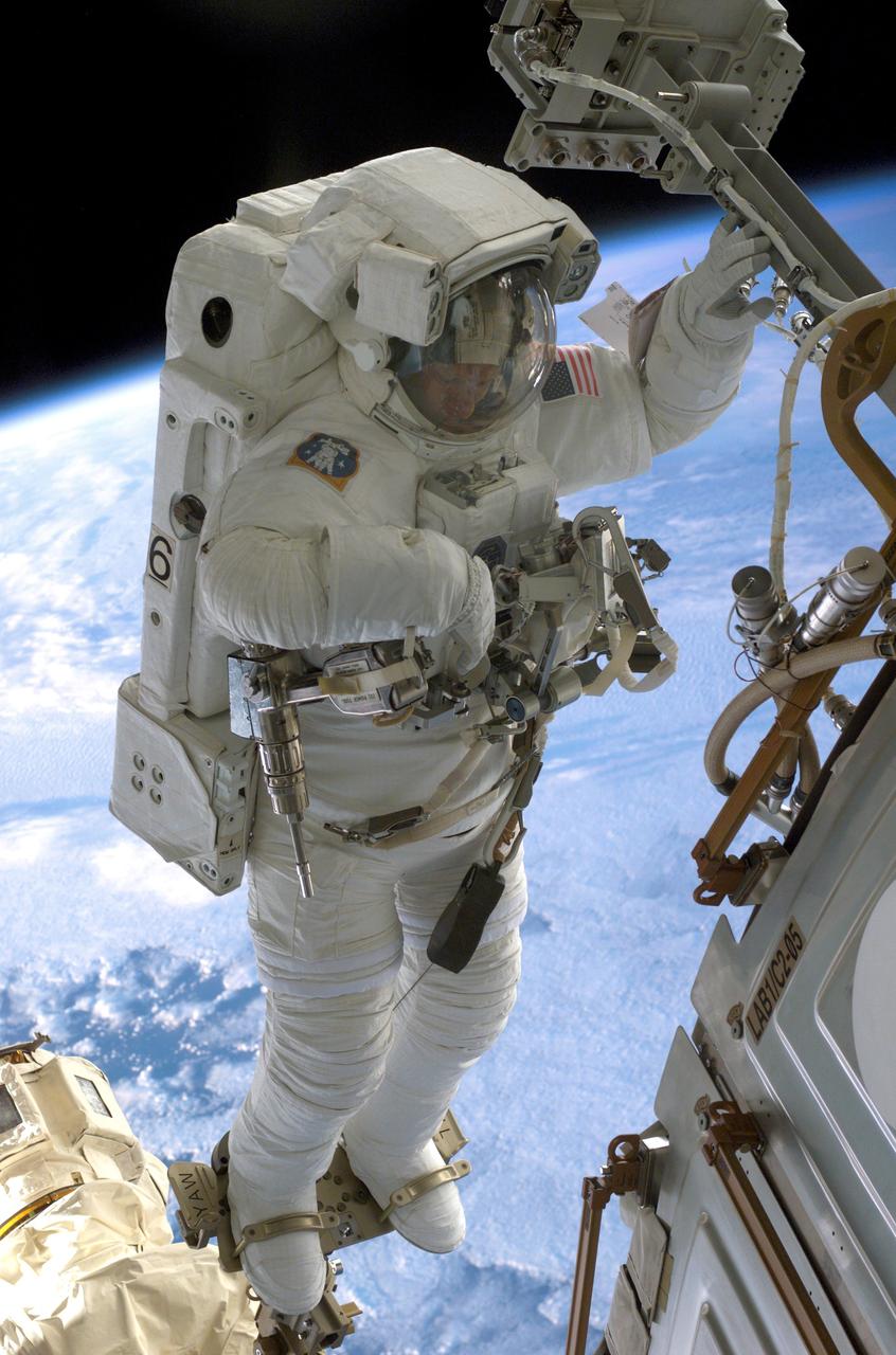
The 16th American assembly flight and 112th overall American flight to the International Space Station (ISS) launched on November 23, 2002 from Kennedy's launch pad 39A aboard the Space Shuttle Orbiter Endeavour STS-113. Mission objectives included the delivery of the Expedition Six Crew to the ISS, the return of Expedition Five crew back to Earth, the delivery of the Crew and Equipment Translation Aid (CETA) cart, and the installation and activation of the Port 1 Integrated Truss Assembly (P1). The first major component installed on the left side of the Station, the P1 truss provides an additional three External Thermal Control System radiators. Weighing in at 27,506 pounds, the P1 truss is 45 feet (13.7 meters) long, 15 feet (4.6 meters) wide, and 13 feet (4 meters) high. Three space walks, aided by the use of the Robotic Manipulator Systems of both the Shuttle and the Station, were performed in the installation of P1. In this photograph, astronauts and mission specialists John B. Herrington (left) and Michael E. Lopez-Alegria (right) work near the CETA cart on a truss on the ISS during a scheduled space walk for the mission. The final major task of the space walk was the relocation of the CETA cart from the Port One (P1) to the Starboard One (S1) Truss, which will allow the Mobile Transporter to move along the P1 to assist in upcoming assembly missions.
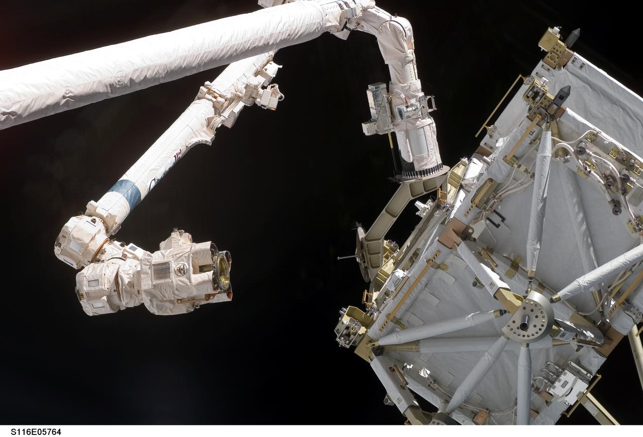
S116-E-05764 (11 Dec. 2006) --- The International Space Station's Canadarm2 moves toward the station's new P5 truss section for a hand-off from Space Shuttle Discovery's Remote Manipulator System (RMS) robotic arm.
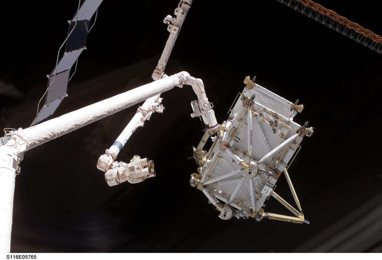
S116-E-05765 (11 Dec. 2006) --- The International Space Station's Canadarm2 moves toward the station's new P5 truss section for a hand-off from Space Shuttle Discovery's Remote Manipulator System (RMS) robotic arm.
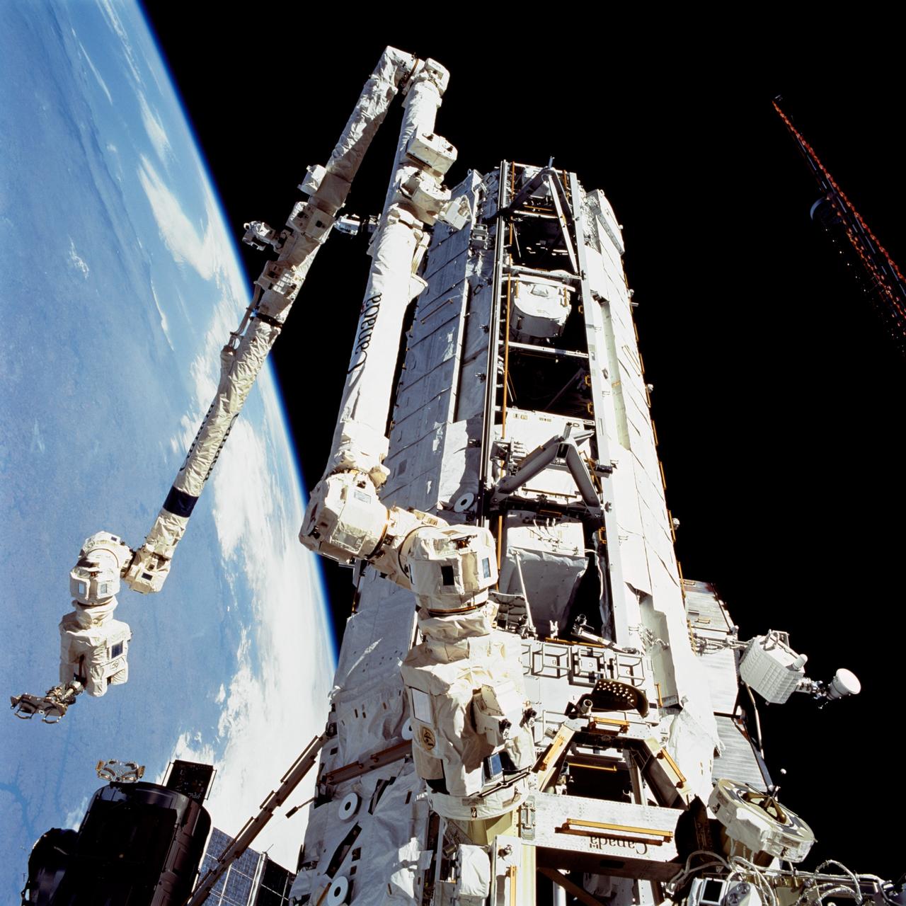
STS112-709-033 (12 October 2002) --- A view of the Starboard One (S1) Truss newly installed on the International Space Station (ISS) as photographed during the mission’s second scheduled session of extravehicular activity (EVA). The station’s Canadarm2 is visible in left frame.
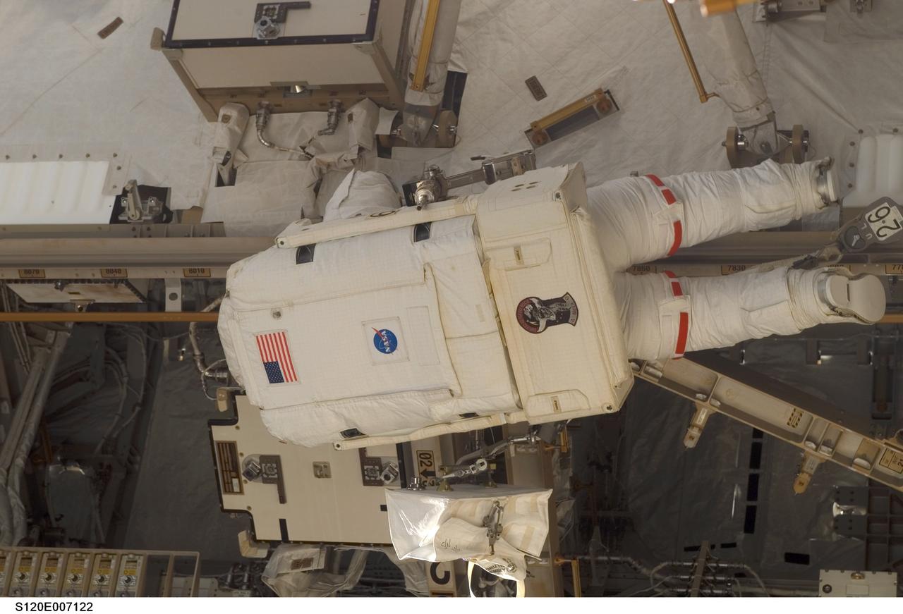
S120-E-007122 (28 Oct. 2007) --- Astronaut Daniel Tani, Expedition 16 flight engineer, participates in the second of five scheduled sessions of extravehicular activity (EVA) as construction continues on the International Space Station. During the 6-hour, 33-minute spacewalk Tani and astronaut Scott Parazynski (out of frame), STS-120 mission specialist, worked in tandem to disconnect cables from the P6 truss, allowing it to be removed from the Z1 truss. Tani also visually inspected the station's starboard Solar Alpha Rotary Joint (SARJ) and gathered samples of "shavings" he found under the joint's multi-layer insulation covers. Also the spacewalkers outfitted the Harmony module, mated the power and data grapple fixture and reconfigured connectors on the starboard 1 (S1) truss that will allow the radiator on S1 to be deployed from the ground later.
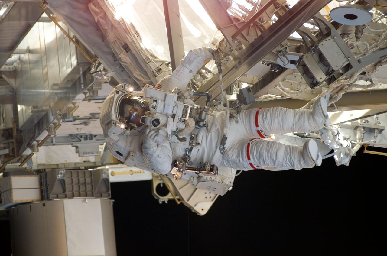
S120-E-007100 (28 Oct. 2007) --- Astronaut Daniel Tani, Expedition 16 flight engineer, participates in the second of five scheduled sessions of extravehicular activity (EVA) as construction continues on the International Space Station. During the 6-hour, 33-minute spacewalk Tani and astronaut Scott Parazynski (out of frame), STS-120 mission specialist, worked in tandem to disconnect cables from the P6 truss, allowing it to be removed from the Z1 truss. Tani also visually inspected the station's starboard Solar Alpha Rotary Joint (SARJ) and gathered samples of "shavings" he found under the joint's multi-layer insulation covers. Also the spacewalkers outfitted the Harmony module, mated the power and data grapple fixture and reconfigured connectors on the starboard 1 (S1) truss that will allow the radiator on S1 to be deployed from the ground later.
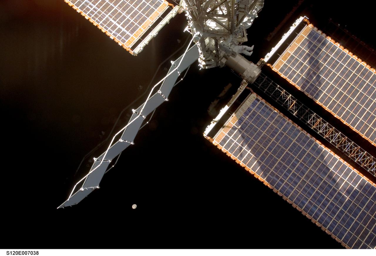
S120-E-007038 (28 Oct. 2007) --- Astronaut Daniel Tani (top center), Expedition 16 flight engineer, participates in the second of five scheduled sessions of extravehicular activity (EVA) as construction continues on the International Space Station. During the 6-hour, 33-minute spacewalk Tani and astronaut Scott Parazynski (out of frame), STS-120 mission specialist, worked in tandem to disconnect cables from the P6 truss, allowing it to be removed from the Z1 truss. Tani also visually inspected the station's starboard Solar Alpha Rotary Joint (SARJ) and gathered samples of "shavings" he found under the joint's multi-layer insulation covers. Also the spacewalkers outfitted the Harmony module, mated the power and data grapple fixture and reconfigured connectors on the starboard 1 (S1) truss that will allow the radiator on S1 to be deployed from the ground later. The moon is visible at lower center.
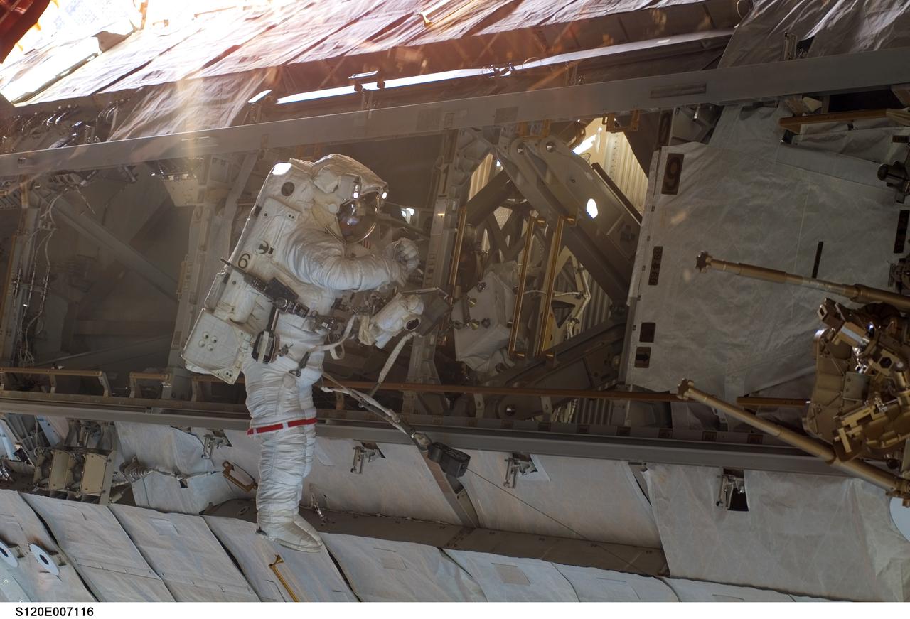
S120-E-007116 (28 Oct. 2007) --- Astronaut Daniel Tani, Expedition 16 flight engineer, participates in the second of five scheduled sessions of extravehicular activity (EVA) as construction continues on the International Space Station. During the 6-hour, 33-minute spacewalk Tani and astronaut Scott Parazynski (out of frame), STS-120 mission specialist, worked in tandem to disconnect cables from the P6 truss, allowing it to be removed from the Z1 truss. Tani also visually inspected the station's starboard Solar Alpha Rotary Joint (SARJ) and gathered samples of "shavings" he found under the joint's multi-layer insulation covers. Also the spacewalkers outfitted the Harmony module, mated the power and data grapple fixture and reconfigured connectors on the starboard 1 (S1) truss that will allow the radiator on S1 to be deployed from the ground later.
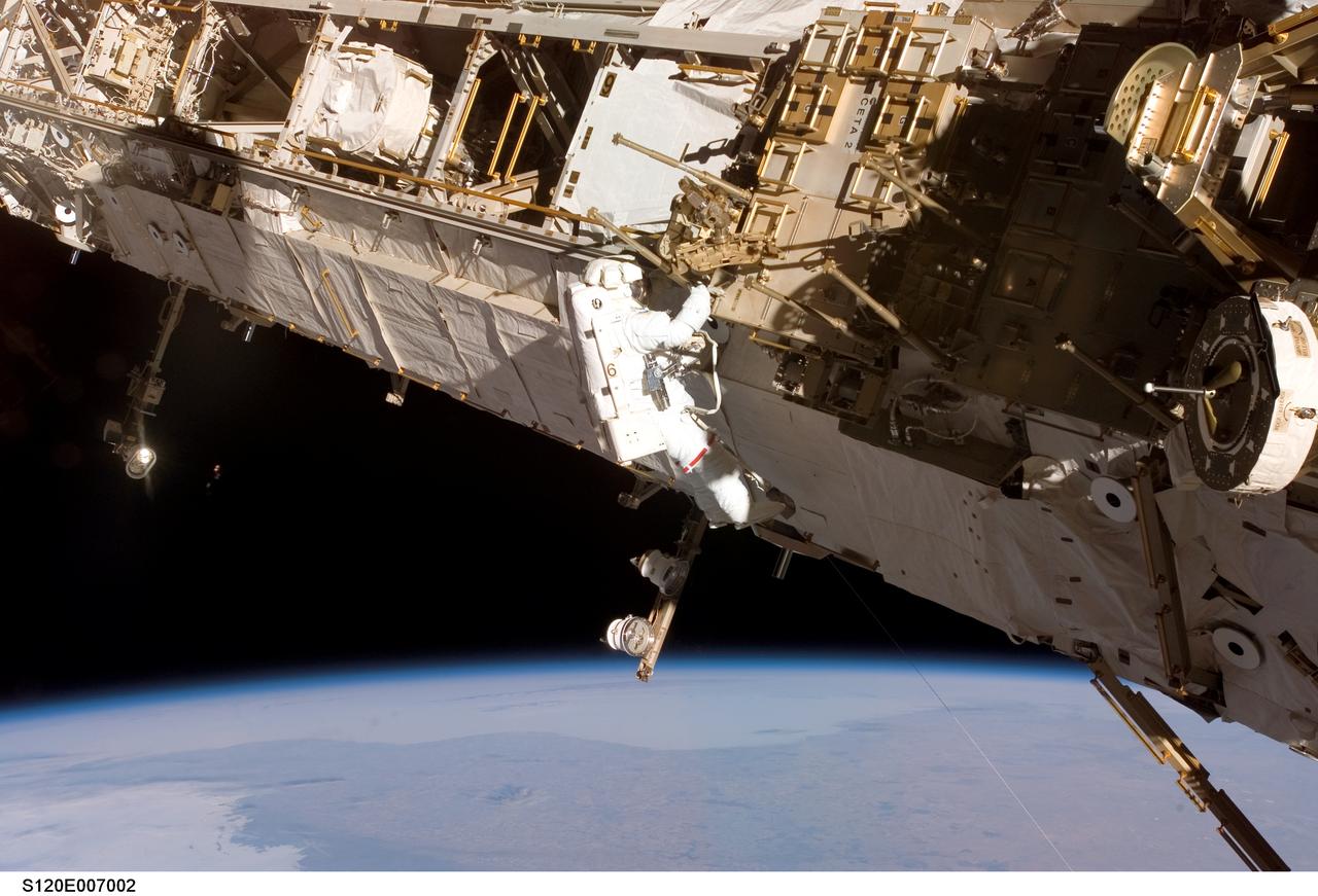
S120-E-007002 (28 Oct. 2007) --- Astronaut Daniel Tani, Expedition 16 flight engineer, participates in the second of five scheduled sessions of extravehicular activity (EVA) as construction continues on the International Space Station. During the 6-hour, 33-minute spacewalk Tani and astronaut Scott Parazynski (out of frame), STS-120 mission specialist, worked in tandem to disconnect cables from the P6 truss, allowing it to be removed from the Z1 truss. Tani also visually inspected the station's starboard Solar Alpha Rotary Joint (SARJ) and gathered samples of "shavings" he found under the joint's multi-layer insulation covers. Also the spacewalkers outfitted the Harmony module, mated the power and data grapple fixture and reconfigured connectors on the starboard 1 (S1) truss that will allow the radiator on S1 to be deployed from the ground later.
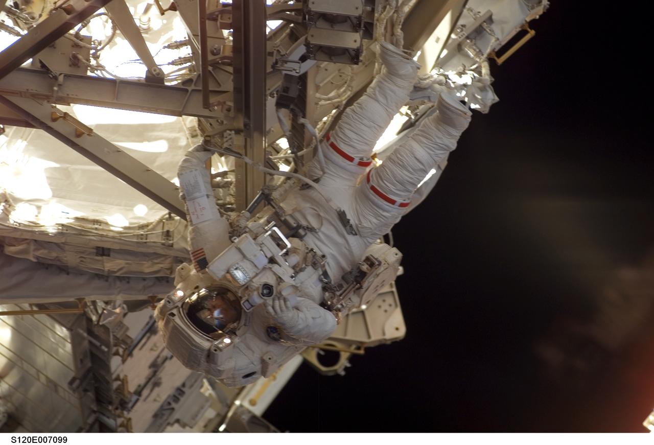
S120-E-007099 (28 Oct. 2007) --- Astronaut Daniel Tani, Expedition 16 flight engineer, participates in the second of five scheduled sessions of extravehicular activity (EVA) as construction continues on the International Space Station. During the 6-hour, 33-minute spacewalk Tani and astronaut Scott Parazynski (out of frame), STS-120 mission specialist, worked in tandem to disconnect cables from the P6 truss, allowing it to be removed from the Z1 truss. Tani also visually inspected the station's starboard Solar Alpha Rotary Joint (SARJ) and gathered samples of "shavings" he found under the joint's multi-layer insulation covers. Also the spacewalkers outfitted the Harmony module, mated the power and data grapple fixture and reconfigured connectors on the starboard 1 (S1) truss that will allow the radiator on S1 to be deployed from the ground later.
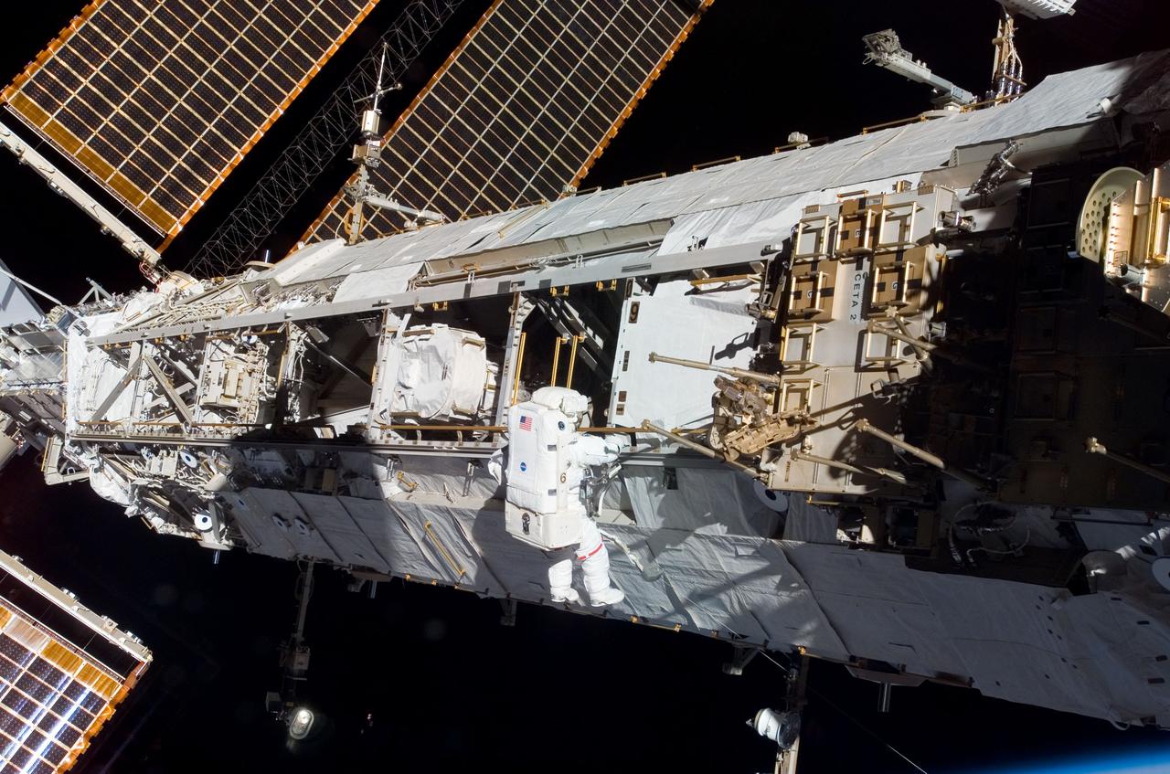
S120-E-007003 (28 Oct. 2007) --- Astronaut Daniel Tani, Expedition 16 flight engineer, participates in the second of five scheduled sessions of extravehicular activity (EVA) as construction continues on the International Space Station. During the 6-hour, 33-minute spacewalk Tani and astronaut Scott Parazynski (out of frame), STS-120 mission specialist, worked in tandem to disconnect cables from the P6 truss, allowing it to be removed from the Z1 truss. Tani also visually inspected the station's starboard Solar Alpha Rotary Joint (SARJ) and gathered samples of "shavings" he found under the joint's multi-layer insulation covers. Also the spacewalkers outfitted the Harmony module, mated the power and data grapple fixture and reconfigured connectors on the starboard 1 (S1) truss that will allow the radiator on S1 to be deployed from the ground later.
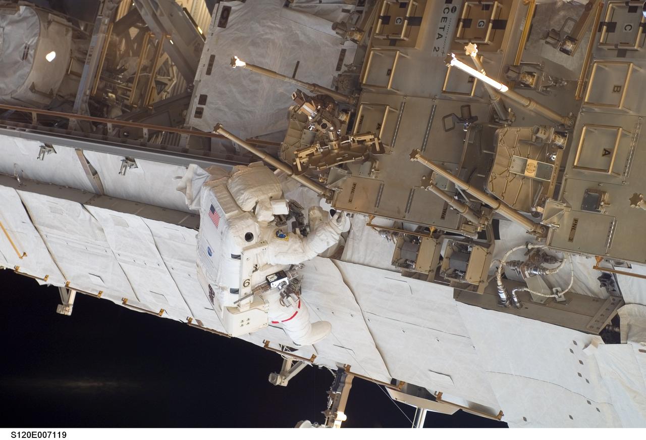
S120-E-007119 (28 Oct. 2007) --- Astronaut Daniel Tani, Expedition 16 flight engineer, participates in the second of five scheduled sessions of extravehicular activity (EVA) as construction continues on the International Space Station. During the 6-hour, 33-minute spacewalk Tani and astronaut Scott Parazynski (out of frame), STS-120 mission specialist, worked in tandem to disconnect cables from the P6 truss, allowing it to be removed from the Z1 truss. Tani also visually inspected the station's starboard Solar Alpha Rotary Joint (SARJ) and gathered samples of "shavings" he found under the joint's multi-layer insulation covers. Also the spacewalkers outfitted the Harmony module, mated the power and data grapple fixture and reconfigured connectors on the starboard 1 (S1) truss that will allow the radiator on S1 to be deployed from the ground later.

KENNEDY SPACE CENTER, FLA. -- In the Orbiter Processing Facility bay 2, Endeavour's payload bay doors are ready to be closed. The payload will be installed on the launch pad after rollout. The orbiter is designated for mission STS-118, targeted for launch on Aug. 9. The mission will continue space station construction by delivering a third starboard truss segment, S5, as well as carrying the External Stowage Platform 3. The crew comprises seven astronauts: Commander Scott Kelly, Pilot Charles Hobaugh and Mission Specialists Dr. Dafydd (Dave) Williams, Barbara Morgan, Richard Mastracchio, Tracy Caldwell and Benjamin Drew. Williams represents the Canadian Space Agency. Photo credit: NASA/Cory Huston
KENNEDY SPACE CENTER, FLA. -- In the Orbiter Processing Facility bay 2, Endeavour's payload bay doors are being closed. The payload will be installed on the launch pad after rollout. The orbiter is designated for mission STS-118, targeted for launch on Aug. 9. The mission will continue space station construction by delivering a third starboard truss segment, S5, as well as carrying the External Stowage Platform 3. The crew comprises seven astronauts: Commander Scott Kelly, Pilot Charles Hobaugh and Mission Specialists Dr. Dafydd (Dave) Williams, Barbara Morgan, Richard Mastracchio, Tracy Caldwell and Benjamin Drew. Williams represents the Canadian Space Agency. Photo credit: NASA/Cory Huston
KENNEDY SPACE CENTER, FLA. -- In the Orbiter Processing Facility bay 2, Endeavour's payload bay doors are closed. The payload will be installed on the launch pad after rollout. The orbiter is designated for mission STS-118, targeted for launch on Aug. 9. The mission will continue space station construction by delivering a third starboard truss segment, S5, as well as carrying the External Stowage Platform 3. The crew comprises seven astronauts: Commander Scott Kelly, Pilot Charles Hobaugh and Mission Specialists Dr. Dafydd (Dave) Williams, Barbara Morgan, Richard Mastracchio, Tracy Caldwell and Benjamin Drew. Williams represents the Canadian Space Agency. Photo credit: NASA/Cory Huston