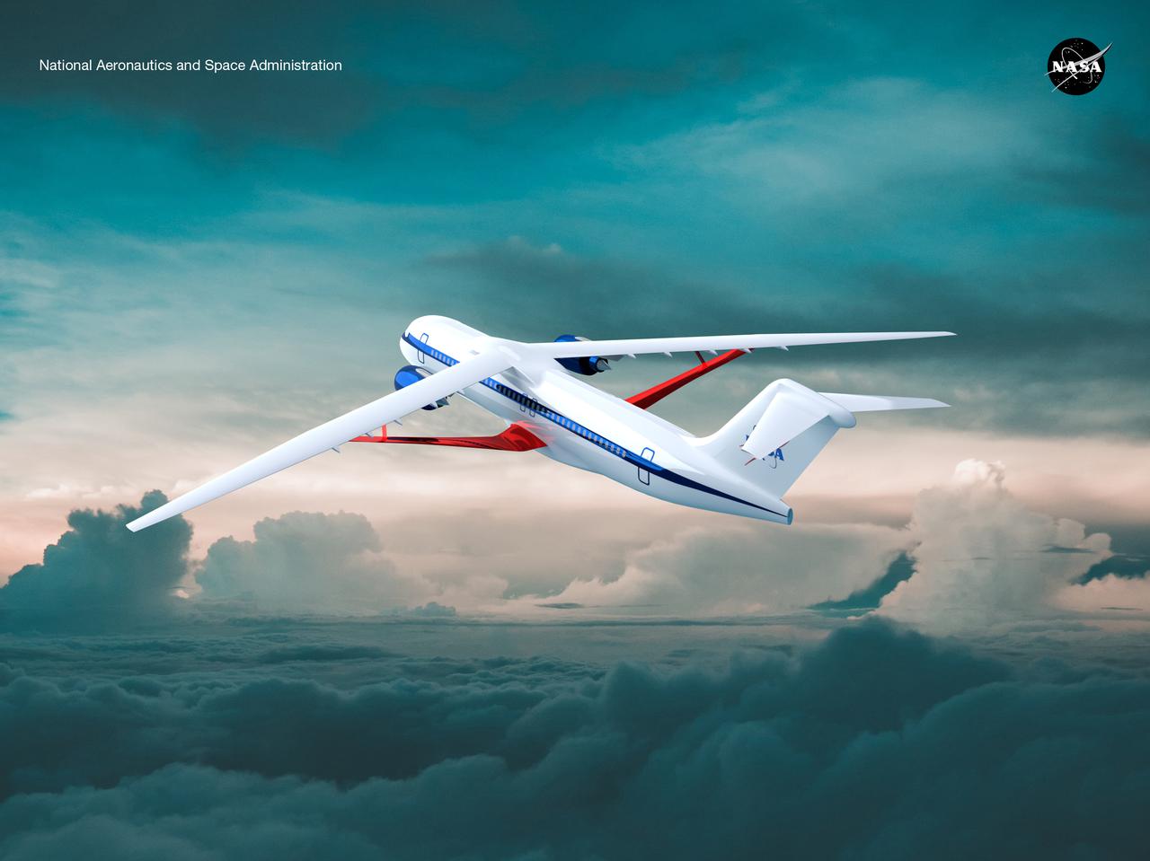
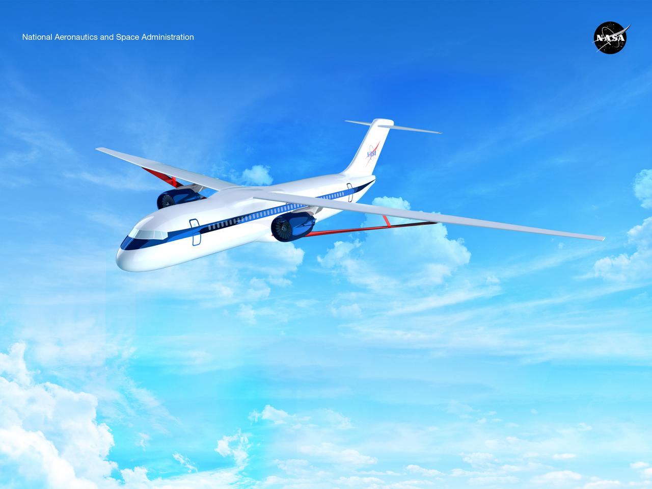
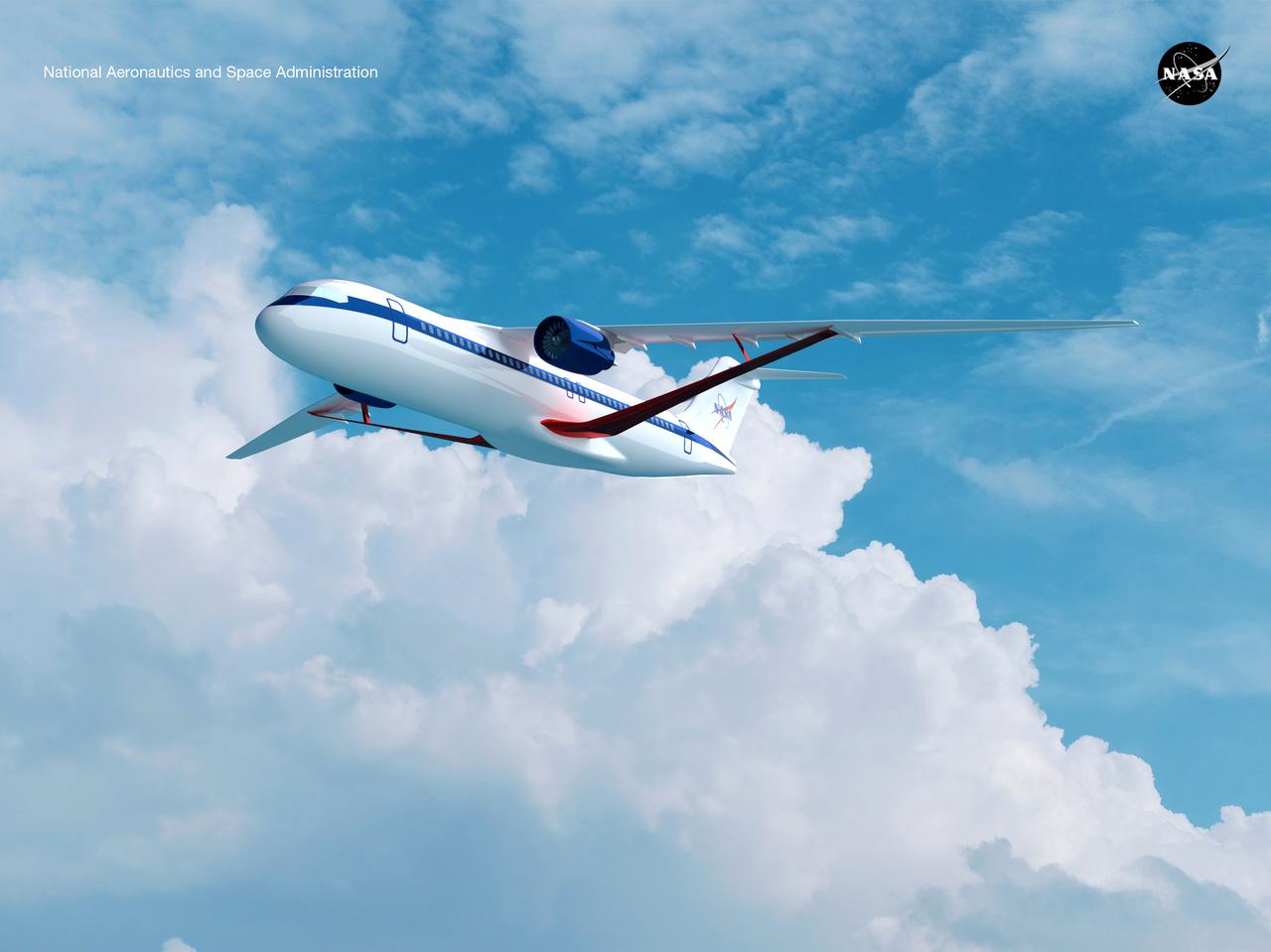
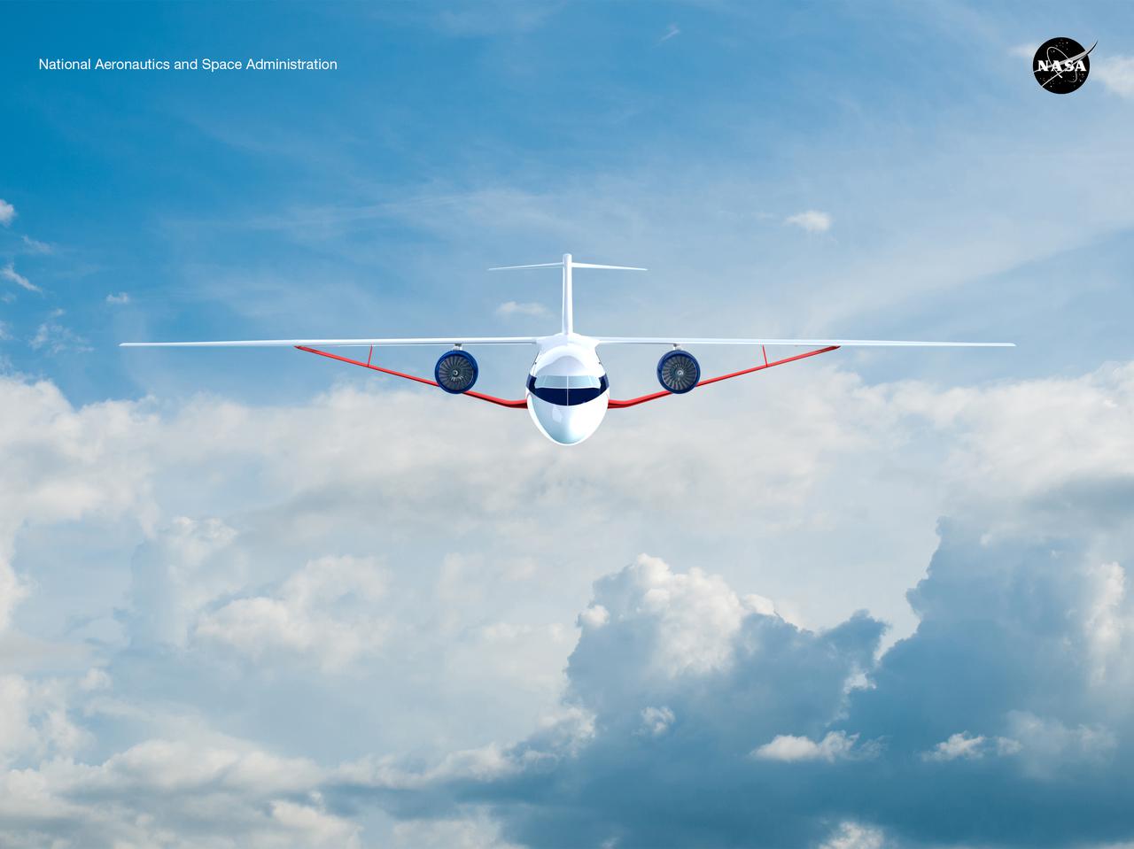
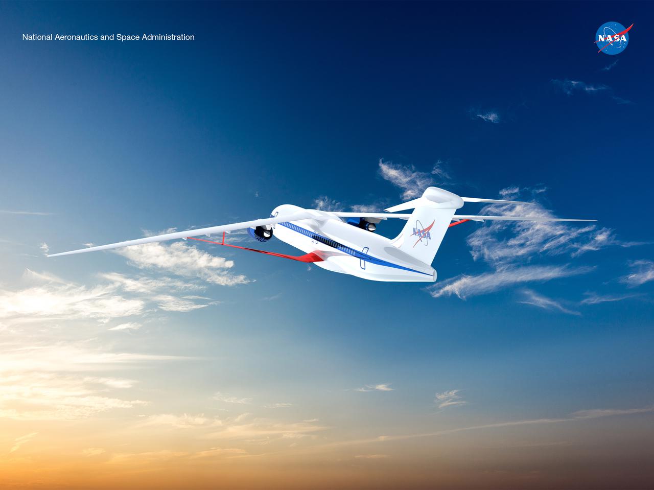
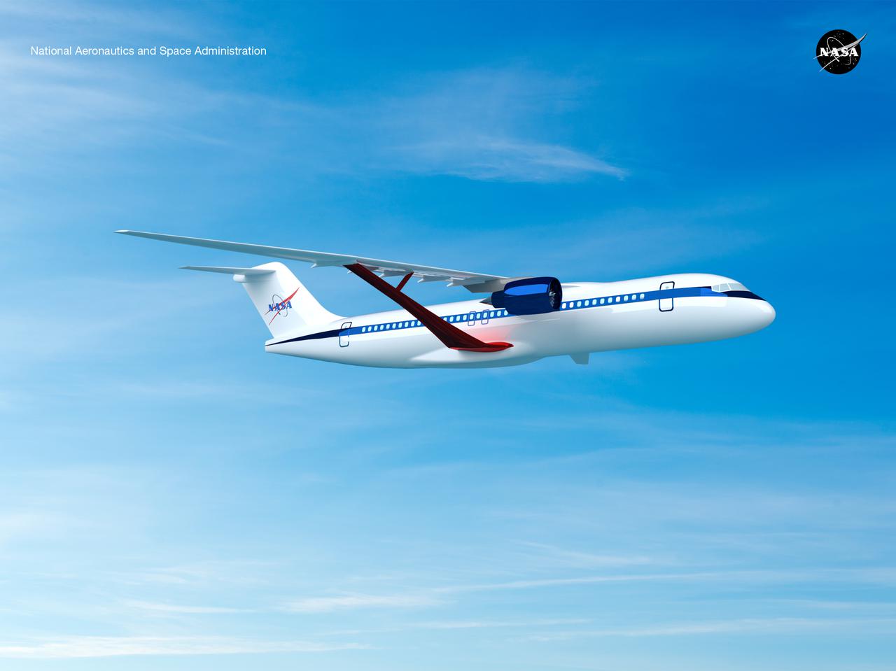
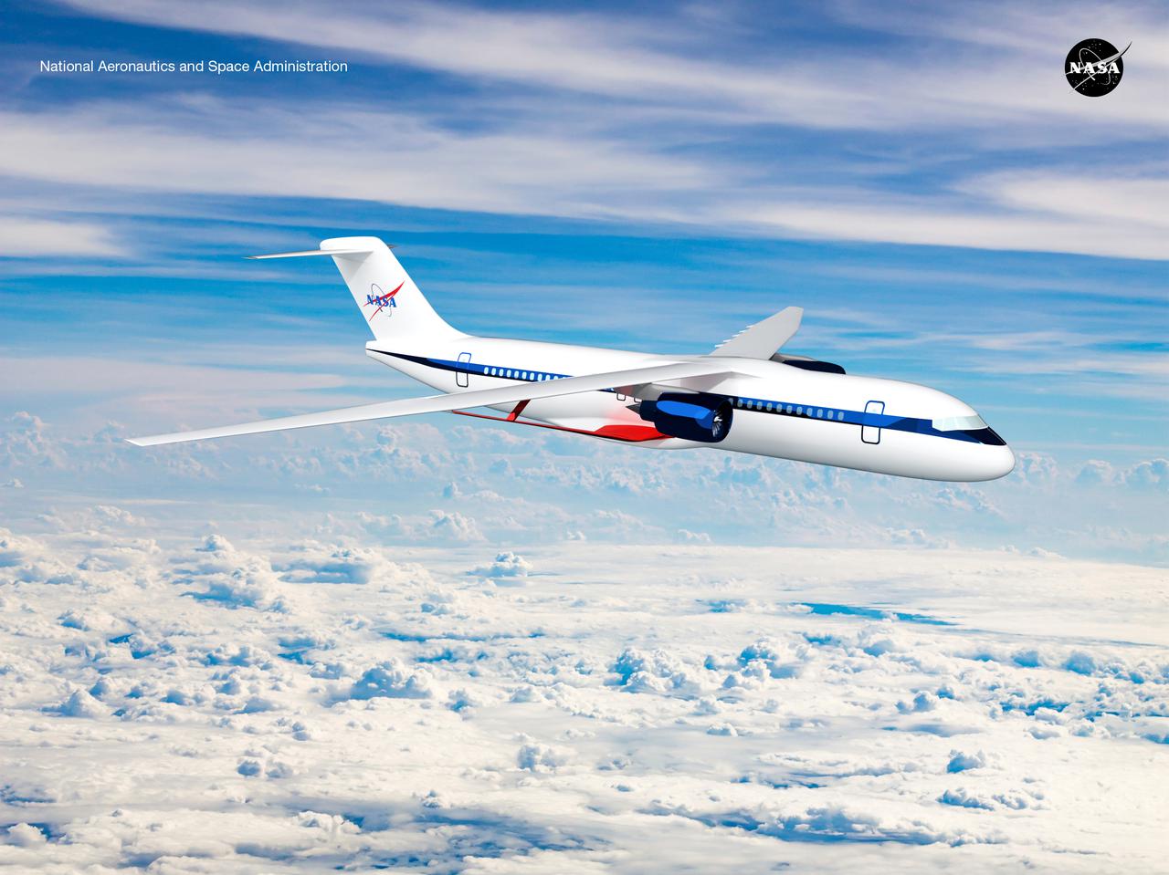
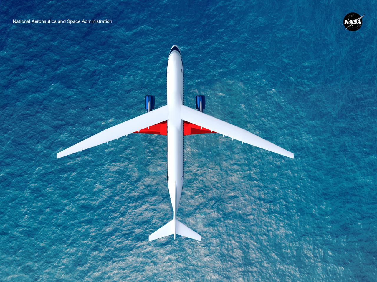
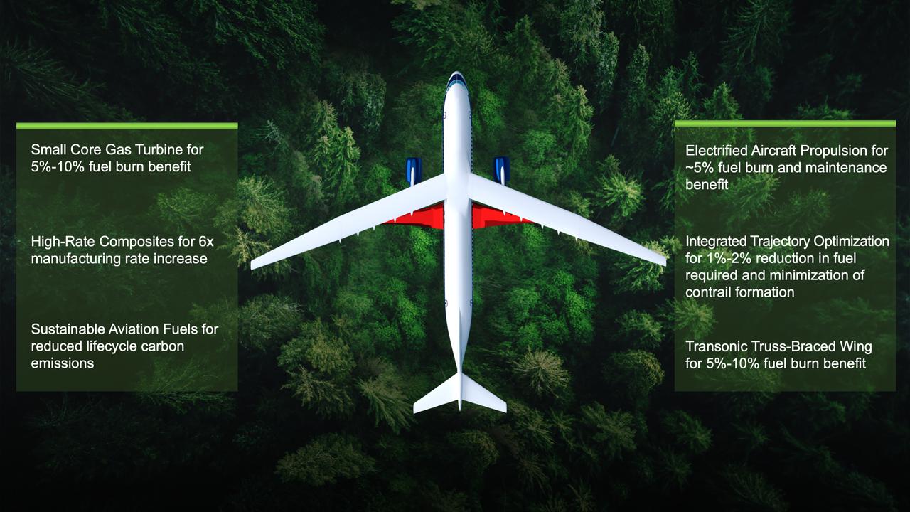
Notice anything different about the wings on this airliner? This conceptual truss-braced wing narrowbody is an aircraft with a 170ft span folding wing. By utilizing trusses, the aircraft can have longer, thinner wings with greater aspect ratios. This, in turn, translates into less drag and 5-10% less fuel burned. The Transonic Truss-Braced Wing aircraft originated from a joint effort by NASA and Boeing to develop subsonic commercial transport concepts – meeting NASA-defined metrics in terms of reduced noise, emissions, and fuel consumption. The design is currently undergoing wind tunnel testing and other studies by NASA researchers.
Notice anything different about the wings on this airliner? This conceptual truss-braced wing narrowbody is an aircraft with a 170ft span folding wing. By utilizing trusses, the aircraft can have longer, thinner wings with greater aspect ratios. This, in turn, translates into less drag and 5-10% less fuel burned. The Transonic Truss-Braced Wing aircraft originated from a joint effort by NASA and Boeing to develop subsonic commercial transport concepts – meeting NASA-defined metrics in terms of reduced noise, emissions, and fuel consumption. The design is currently undergoing wind tunnel testing and other studies by NASA researchers.
Notice anything different about the wings on this airliner? This conceptual truss-braced wing narrowbody is an aircraft with a 170ft span folding wing. By utilizing trusses, the aircraft can have longer, thinner wings with greater aspect ratios. This, in turn, translates into less drag and 5-10% less fuel burned. The Transonic Truss-Braced Wing aircraft originated from a joint effort by NASA and Boeing to develop subsonic commercial transport concepts – meeting NASA-defined metrics in terms of reduced noise, emissions, and fuel consumption. The design is currently undergoing wind tunnel testing and other studies by NASA researchers.
Notice anything different about the wings on this airliner? This conceptual truss-braced wing narrowbody is an aircraft with a 170ft span folding wing. By utilizing trusses, the aircraft can have longer, thinner wings with greater aspect ratios. This, in turn, translates into less drag and 5-10% less fuel burned. The Transonic Truss-Braced Wing aircraft originated from a joint effort by NASA and Boeing to develop subsonic commercial transport concepts – meeting NASA-defined metrics in terms of reduced noise, emissions, and fuel consumption. The design is currently undergoing wind tunnel testing and other studies by NASA researchers.
Notice anything different about the wings on this airliner? This conceptual truss-braced wing narrowbody is an aircraft with a 170ft span folding wing. By utilizing trusses, the aircraft can have longer, thinner wings with greater aspect ratios. This, in turn, translates into less drag and 5-10% less fuel burned. The Transonic Truss-Braced Wing aircraft originated from a joint effort by NASA and Boeing to develop subsonic commercial transport concepts – meeting NASA-defined metrics in terms of reduced noise, emissions, and fuel consumption. The design is currently undergoing wind tunnel testing and other studies by NASA researchers.
Notice anything different about the wings on this airliner? This conceptual truss-braced wing narrowbody is an aircraft with a 170ft span folding wing. By utilizing trusses, the aircraft can have longer, thinner wings with greater aspect ratios. This, in turn, translates into less drag and 5-10% less fuel burned. The Transonic Truss-Braced Wing aircraft originated from a joint effort by NASA and Boeing to develop subsonic commercial transport concepts – meeting NASA-defined metrics in terms of reduced noise, emissions, and fuel consumption. The design is currently undergoing wind tunnel testing and other studies by NASA researchers.
Notice anything different about the wings on this airliner? This conceptual truss-braced wing narrowbody is an aircraft with a 170ft span folding wing. By utilizing trusses, the aircraft can have longer, thinner wings with greater aspect ratios. This, in turn, translates into less drag and 5-10% less fuel burned. The Transonic Truss-Braced Wing aircraft originated from a joint effort by NASA and Boeing to develop subsonic commercial transport concepts – meeting NASA-defined metrics in terms of reduced noise, emissions, and fuel consumption. The design is currently undergoing wind tunnel testing and other studies by NASA researchers.
Notice anything different about the wings on this airliner? This conceptual truss-braced wing narrowbody is an aircraft with a 170ft span folding wing. By utilizing trusses, the aircraft can have longer, thinner wings with greater aspect ratios. This, in turn, translates into less drag and 5-10% less fuel burned. The Transonic Truss-Braced Wing aircraft originated from a joint effort by NASA and Boeing to develop subsonic commercial transport concepts – meeting NASA-defined metrics in terms of reduced noise, emissions, and fuel consumption. The design is currently undergoing wind tunnel testing and other studies by NASA researchers.
Notice anything different about the wings on this airliner? This conceptual truss-braced wing narrowbody is an aircraft with a 170ft span folding wing. By utilizing trusses, the aircraft can have longer, thinner wings with greater aspect ratios. This, in turn, translates into less drag and 5-10% less fuel burned. The Transonic Truss-Braced Wing aircraft originated from a joint effort by NASA and Boeing to develop subsonic commercial transport concepts – meeting NASA-defined metrics in terms of reduced noise, emissions, and fuel consumption. The design is currently undergoing wind tunnel testing and other studies by NASA researchers.
Notice anything different about the wings on this airliner? This conceptual truss-braced wing narrowbody is an aircraft with a 170ft span folding wing. By utilizing trusses, the aircraft can have longer, thinner wings with greater aspect ratios. This, in turn, translates into less drag and 5-10% less fuel burned. The Transonic Truss-Braced Wing aircraft originated from a joint effort by NASA and Boeing to develop subsonic commercial transport concepts – meeting NASA-defined metrics in terms of reduced noise, emissions, and fuel consumption. The design is currently undergoing wind tunnel testing and other studies by NASA researchers.
Notice anything different about the wings on this airliner? This conceptual truss-braced wing narrowbody is an aircraft with a 170ft span folding wing. By utilizing trusses, the aircraft can have longer, thinner wings with greater aspect ratios. This, in turn, translates into less drag and 5-10% less fuel burned. The Transonic Truss-Braced Wing aircraft originated from a joint effort by NASA and Boeing to develop subsonic commercial transport concepts – meeting NASA-defined metrics in terms of reduced noise, emissions, and fuel consumption. The design is currently undergoing wind tunnel testing and other studies by NASA researchers.
Notice anything different about the wings on this airliner? This conceptual truss-braced wing narrowbody is an aircraft with a 170ft span folding wing. By utilizing trusses, the aircraft can have longer, thinner wings with greater aspect ratios. This, in turn, translates into less drag and 5-10% less fuel burned. The Transonic Truss-Braced Wing aircraft originated from a joint effort by NASA and Boeing to develop subsonic commercial transport concepts – meeting NASA-defined metrics in terms of reduced noise, emissions, and fuel consumption. The design is currently undergoing wind tunnel testing and other studies by NASA researchers.
Notice anything different about the wings on this airliner? This conceptual truss-braced wing narrowbody is an aircraft with a 170ft span folding wing. By utilizing trusses, the aircraft can have longer, thinner wings with greater aspect ratios. This, in turn, translates into less drag and 5-10% less fuel burned. The Transonic Truss-Braced Wing aircraft originated from a joint effort by NASA and Boeing to develop subsonic commercial transport concepts – meeting NASA-defined metrics in terms of reduced noise, emissions, and fuel consumption. The design is currently undergoing wind tunnel testing and other studies by NASA researchers.
Notice anything different about the wings on this airliner? This conceptual truss-braced wing narrowbody is an aircraft with a 170ft span folding wing. By utilizing trusses, the aircraft can have longer, thinner wings with greater aspect ratios. This, in turn, translates into less drag and 5-10% less fuel burned. The Transonic Truss-Braced Wing aircraft originated from a joint effort by NASA and Boeing to develop subsonic commercial transport concepts – meeting NASA-defined metrics in terms of reduced noise, emissions, and fuel consumption. The design is currently undergoing wind tunnel testing and other studies by NASA researchers.
Notice anything different about the wings on this airliner? This conceptual truss-braced wing narrowbody is an aircraft with a 170ft span folding wing. By utilizing trusses, the aircraft can have longer, thinner wings with greater aspect ratios. This, in turn, translates into less drag and 5-10% less fuel burned. The Transonic Truss-Braced Wing aircraft originated from a joint effort by NASA and Boeing to develop subsonic commercial transport concepts – meeting NASA-defined metrics in terms of reduced noise, emissions, and fuel consumption. The design is currently undergoing wind tunnel testing and other studies by NASA researchers.
Notice anything different about the wings on this airliner? This conceptual truss-braced wing narrowbody is an aircraft with a 170ft span folding wing. By utilizing trusses, the aircraft can have longer, thinner wings with greater aspect ratios. This, in turn, translates into less drag and 5-10% less fuel burned. The Transonic Truss-Braced Wing aircraft originated from a joint effort by NASA and Boeing to develop subsonic commercial transport concepts – meeting NASA-defined metrics in terms of reduced noise, emissions, and fuel consumption. The design is currently undergoing wind tunnel testing and other studies by NASA researchers.
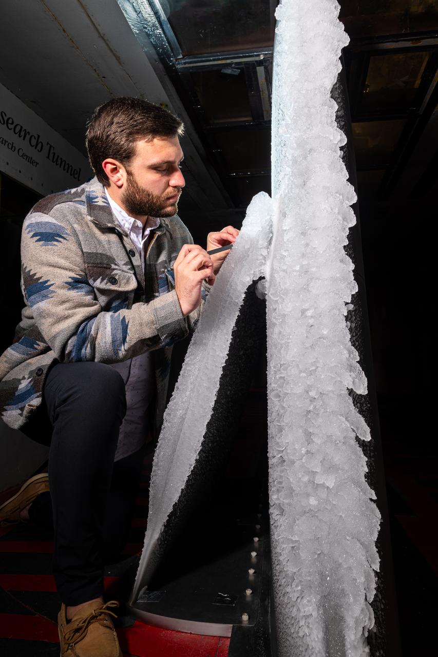
Thomas Ozoroski, an Icing Researcher, is shown documenting ice accretion on the leading edge of the next-generation Transonic Truss-Braced Wing design at NASA Glenn's Icing Research Center. This critical research will help understand icing effects for future, high-lift, ultra-efficient aircraft. Photo Credit: (NASA/Jordan Salkin)
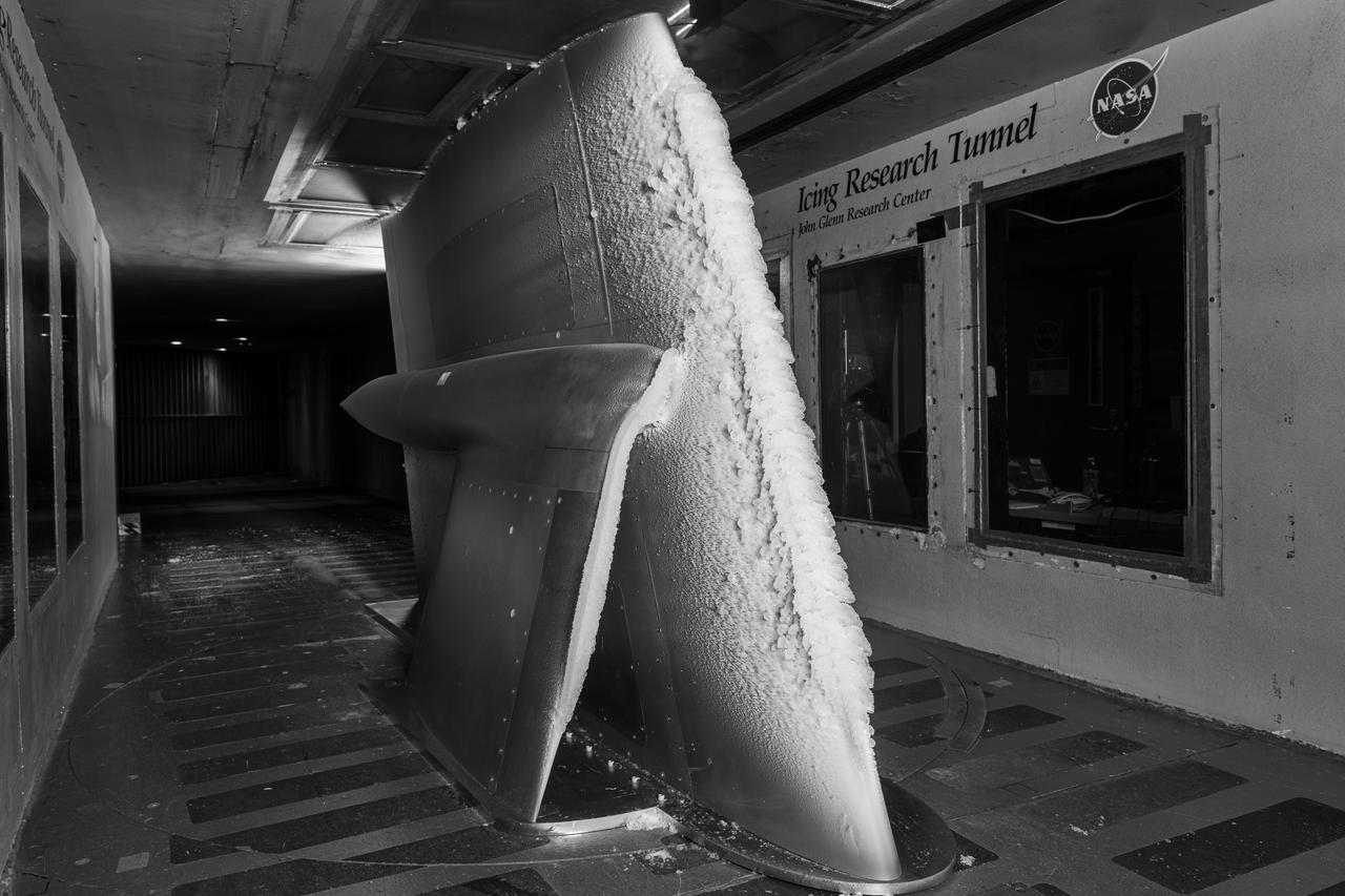
Ice accretion is shown on the leading edge of the next-generation Transonic Truss-Braced Wing design at NASA Glenn's Icing Research Center. This critical research will help understand icing effects for future, high-lift, ultra-efficient aircraft. Photo Credit: (NASA/Jordan Salkin)
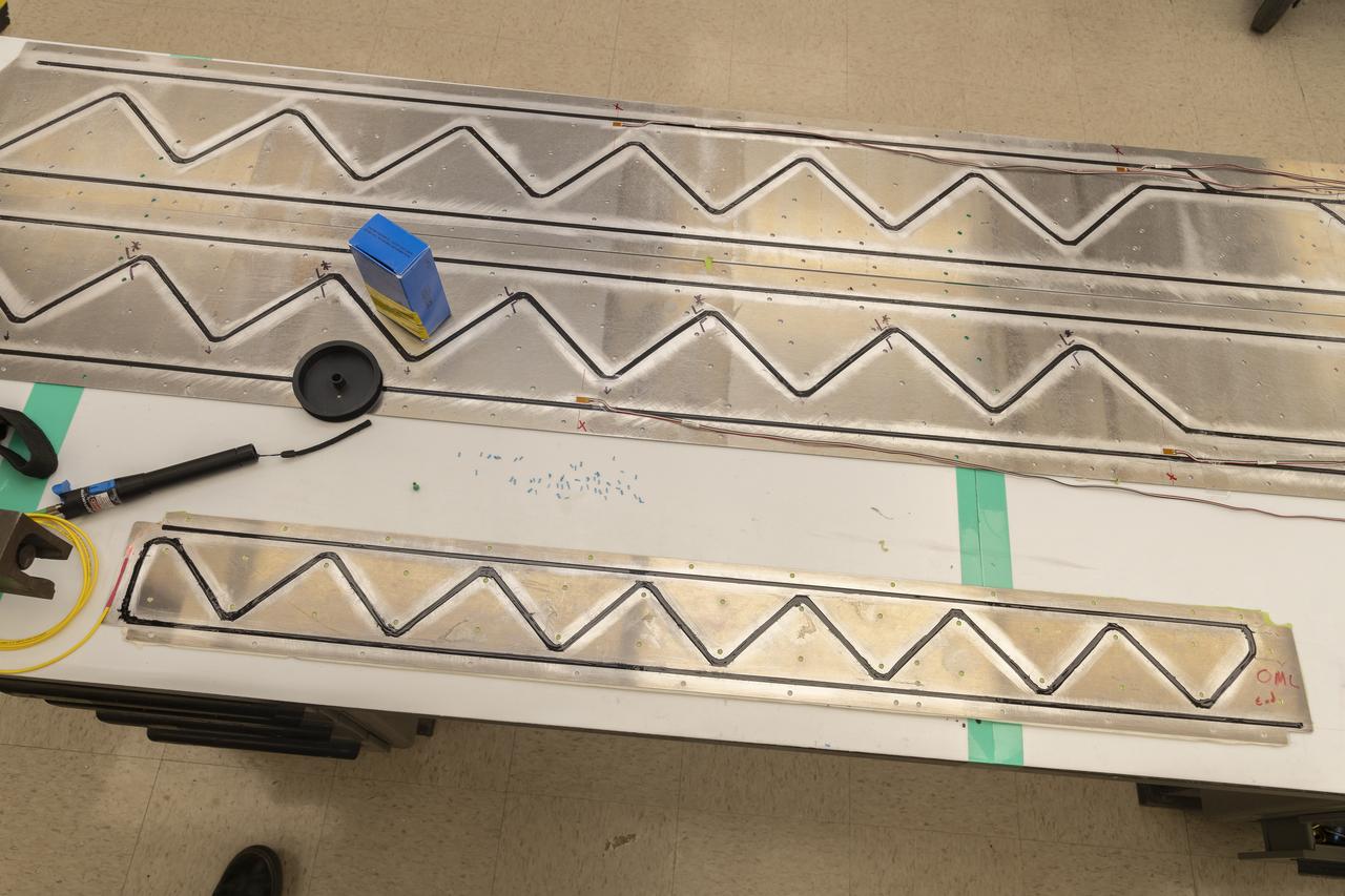
Instrumentation of the wing and strut that comprise the Mock Truss-Braced Wing 10-foot model are complete at NASA’s Armstrong Flight Research Center in Edwards, California.
An artist’s concept of the transonic truss-braced wing aircraft configuration in flight over a forest of trees.
An artist’s concept of the transonic truss-braced wing aircraft configuration in flight over a forest of trees.
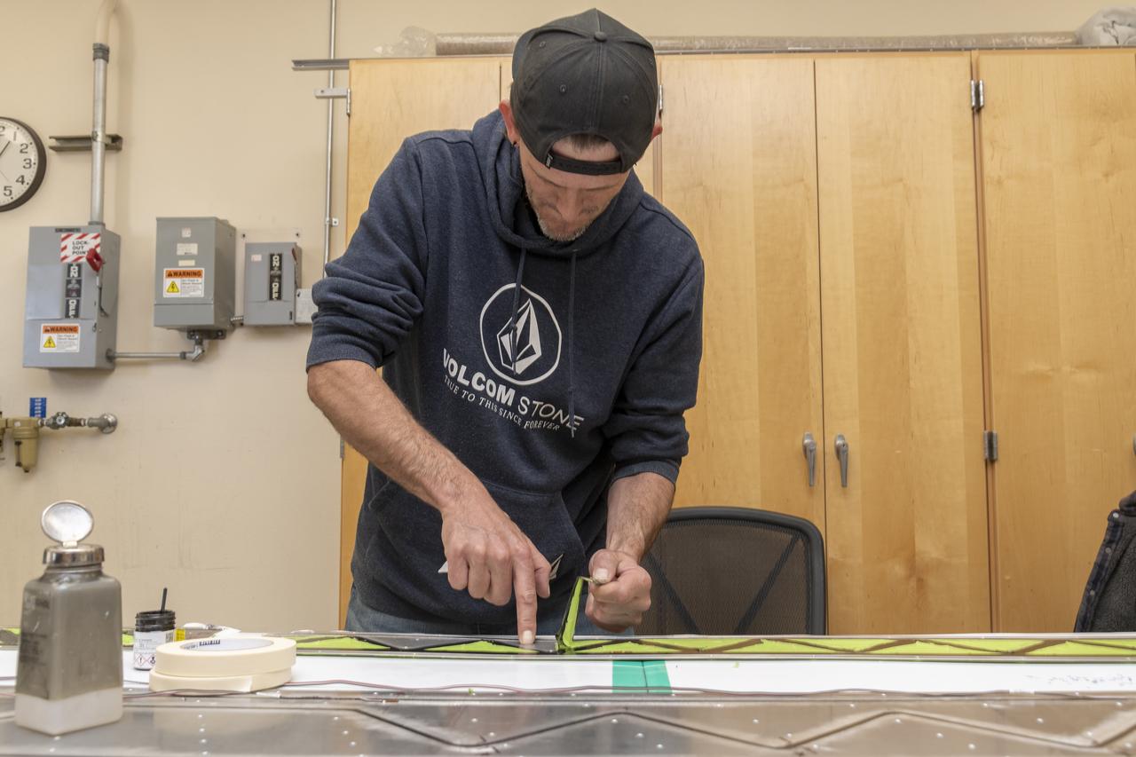
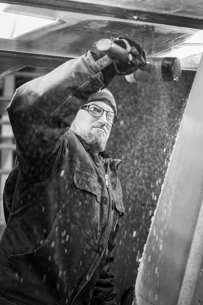
Engineering technician Jeff Howell removes tape from the Mock Truss-Braced Wing 10-foot model at NASA’s Armstrong Flight Research Center in Edwards, California. The tape was used to limit the amount of epoxy on the model wing during the process to secure the fiber optic strain sensors to the wing.
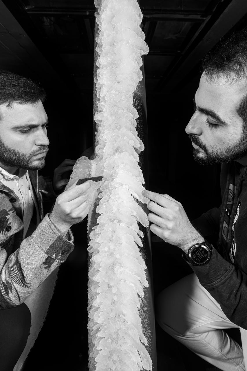
Zaid Sabri and Thomas Ozoroski, Icing Researchers, are shown documenting ice accretion on the leading edge of the next-generation Transonic Truss-Braced Wing design at NASA Glenn's Icing Research Center. This critical research will help understand icing effects for future, high-lift, ultra-efficient aircraft. Photo Credit: (NASA/Jordan Salkin)

Engineering technician Jeff Howell mounts conventional strain gauges to the Mock Truss-Braced Wing 10-foot model at NASA’s Armstrong Flight Research Center in Edwards, California. The conventional system data will be compared the Fiber Optic Sensing System developed at the center on the same wing to see how well the testing methods match.
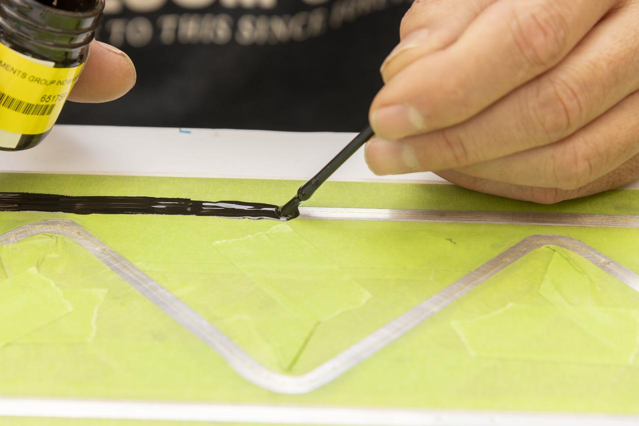
An epoxy is applied to adhere the fiber optic sensor installation on the Mock Truss-Braced Wing 10-foot model at NASA’s Armstrong Flight Research Center in Edwards, California.
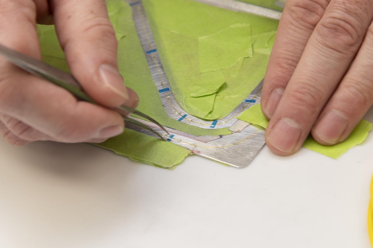
Engineering technician Jeff Howell removes thin pieces of tape from fiber used for a bonding process on the Mock Truss-Braced Wing 10-foot model at NASA’s Armstrong Flight Research Center in Edwards, California.
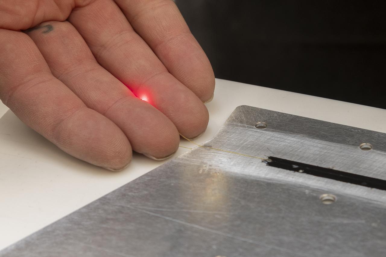
A red light confirms that the fiber of the Fiber Optic Sensing System installed on the Mock Truss-Braced Wing 10-foot model works as intended at NASA’s Armstrong Flight Research Center in Edwards, California. The fiber, which is about the thickness of a human hair, is part of a system that can provide strain information researchers can use to determine the model’s durability.
A technician is shown preparing the research model for its next test condition by removing ice accretion. Photo Credit: (NASA/Jordan Salkin)
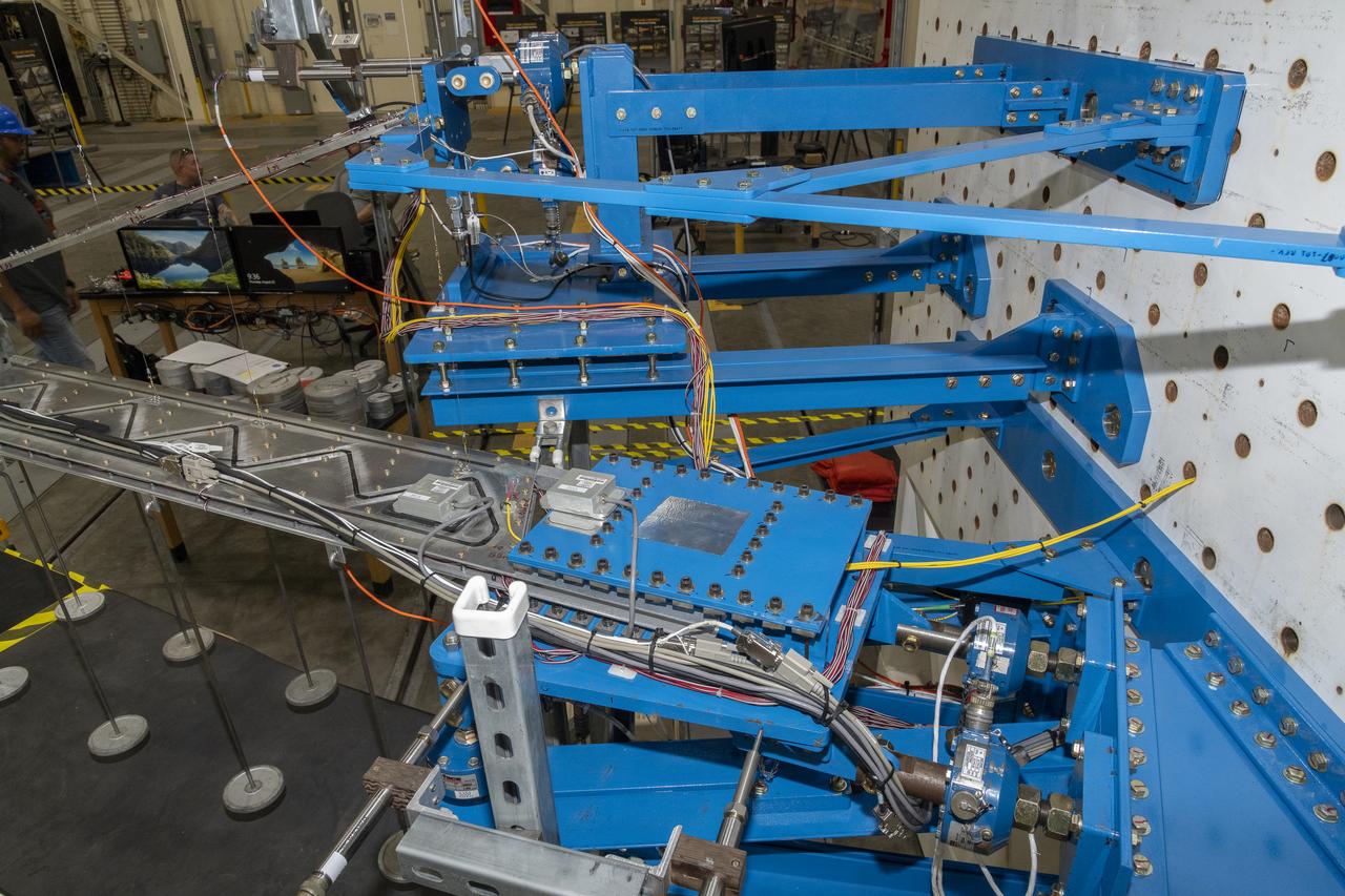
Researchers test a 10-foot Mock Truss-Braced Wing at NASA’s Armstrong Flight Research Center in Edwards, California. The infrastructure, in blue, holds the wing and truss and enables the test. The aircraft concept involves a wing braced on an aircraft using diagonal struts that also add lift and could result in significantly improved aerodynamics.

Matthew Sanchez attaches the strut and the wing to ensure they fit together as intended for a 10-foot model of the Transonic Truss-Braced Wing at NASA’s Armstrong Flight Research Center, in Edwards, California. The aircraft concept involves a wing braced on an aircraft using diagonal struts that also add lift and could result in significantly improved aerodynamics.
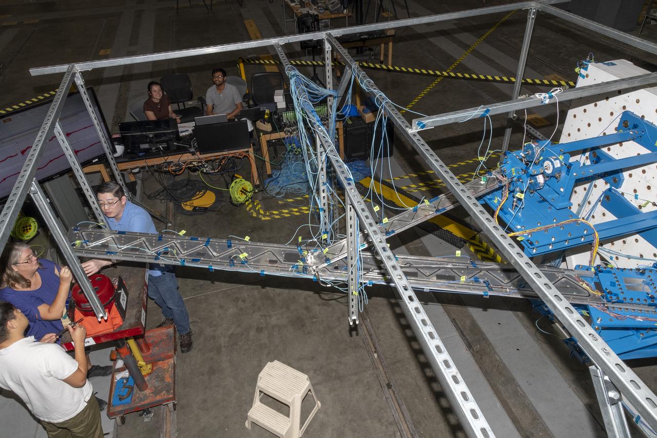
Researchers test a 10-foot Mock Truss-Braced Wing at NASA’s Armstrong Flight Research Center in Edwards, California. A view from above shows the test structure, the wing, and the strut. The aircraft concept involves a wing braced on an aircraft using diagonal struts that also add lift and could result in significantly improved aerodynamics.
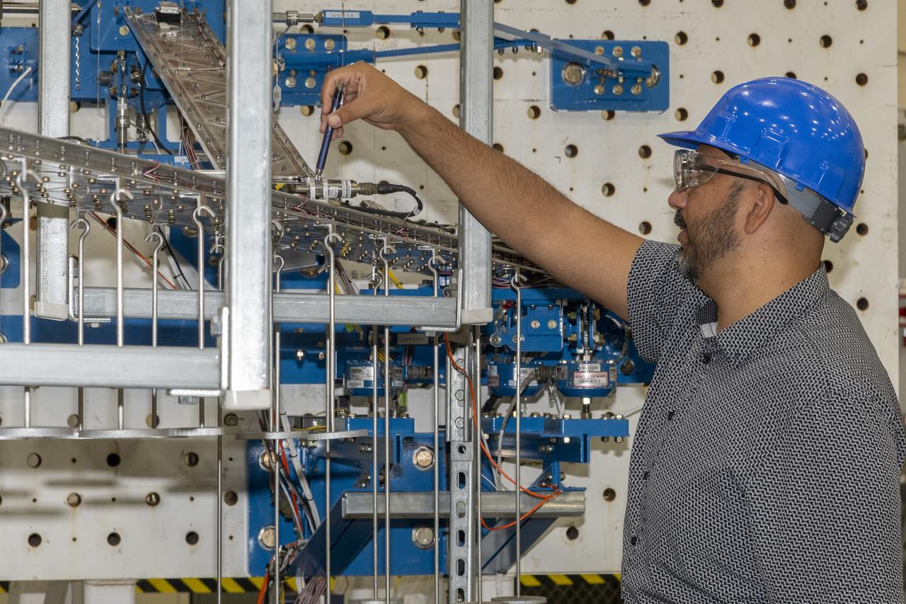
Researchers test a 10-foot Mock Truss-Braced Wing at NASA’s Armstrong Flight Research Center in Edwards, California. Frank Pena, test director, checks the mock wing. The aircraft concept involves a wing braced on an aircraft using diagonal struts that also add lift and could result in significantly improved aerodynamics.
Matthew Sanchez assembles wing ribs for a 10-foot model of the Transonic Truss-Braced Wing at NASA’s Armstrong Flight Research Center, in Edwards, California. The aircraft concept involves a wing braced on an aircraft using diagonal struts that also add lift and could result in significantly improved aerodynamics.
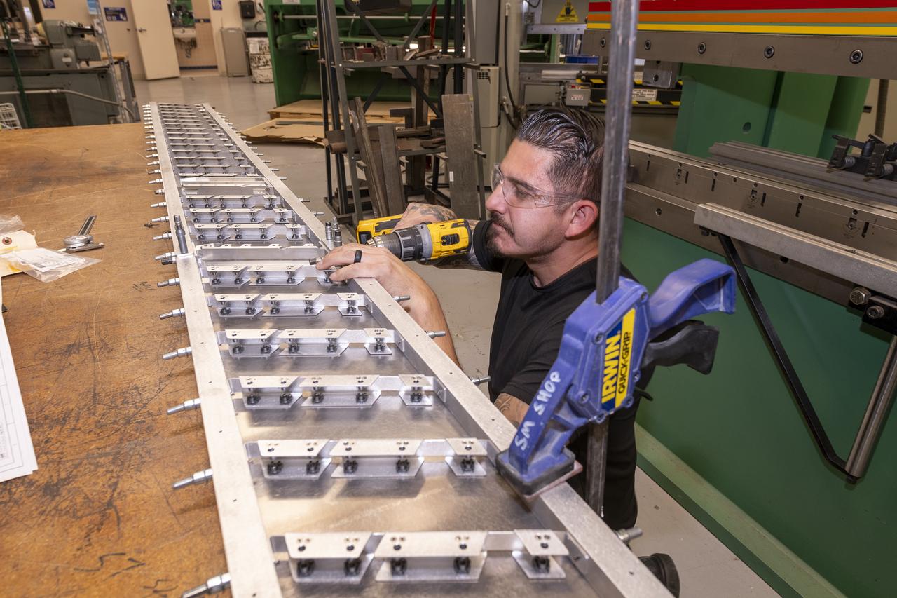
Matthew Sanchez assembles wing ribs to the 10-foot model of the Transonic Truss-Braced Wing at NASA’s Armstrong Flight Research Center, in Edwards, California. The aircraft concept involves a wing braced on an aircraft using diagonal struts that also add lift and could result in significantly improved aerodynamics.
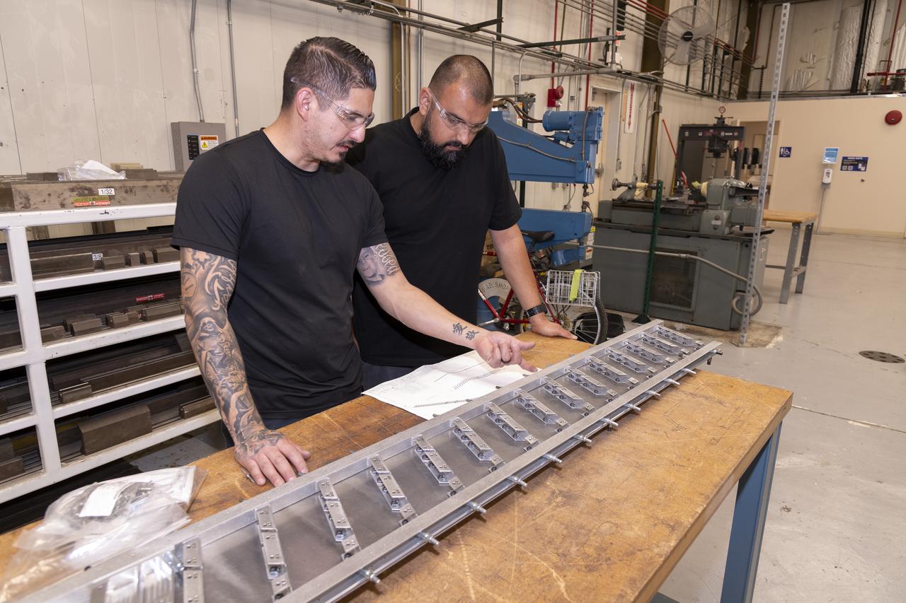
Matthew Sanchez, left, consults with Sal Navarro on assembling wing ribs to the 10-foot model of the Transonic Truss-Braced Wing at NASA’s Armstrong Flight Research Center, in Edwards, California. The aircraft concept involves a wing braced on an aircraft using diagonal struts that also add lift and could result in significantly improved aerodynamics.
Matthew Sanchez attaches the strut and the wing to ensure they fit together as intended for a 10-foot model of the Transonic Truss-Braced Wing at NASA’s Armstrong Flight Research Center, in Edwards, California. The aircraft concept involves a wing braced on an aircraft using diagonal struts that also add lift and could result in significantly improved aerodynamics.
NASA will demonstrate high-risk, high-payoff technology advancements critical for U.S. aerospace manufacturers to bring to market innovative, cost-effective, and sustainable products and services demanded by airlines and customers.
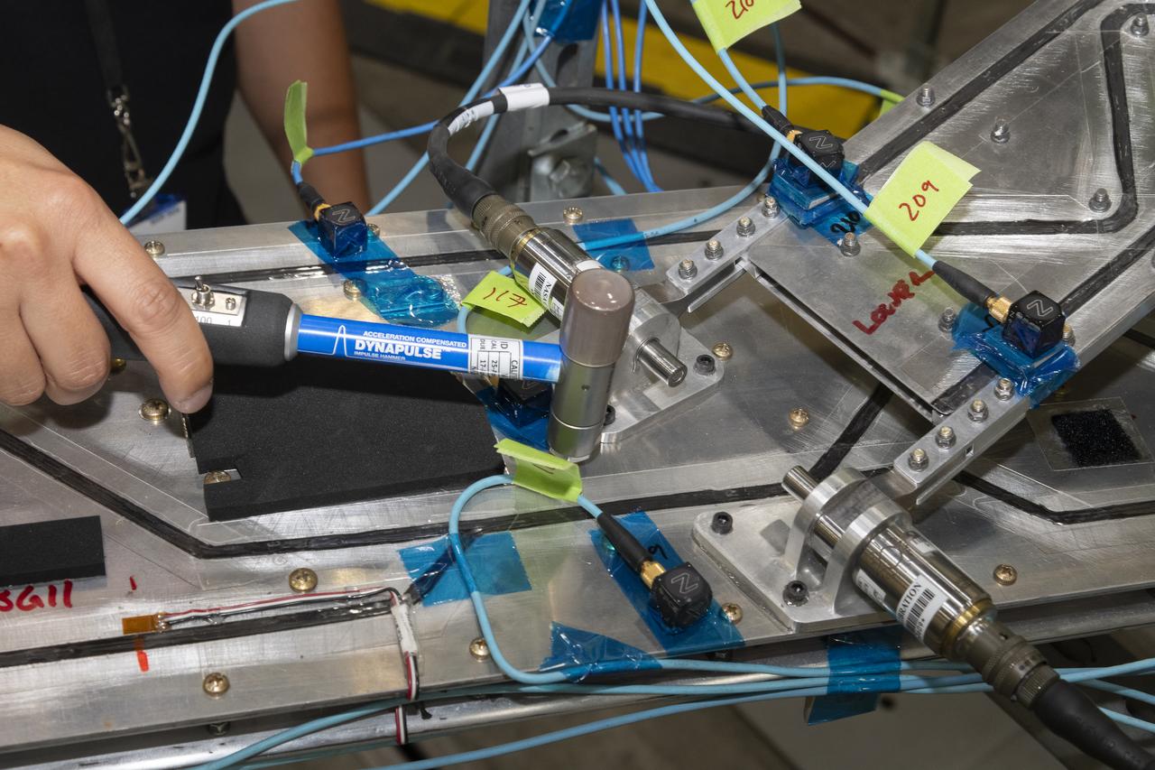
Researchers test a 10-foot Mock Truss-Braced Wing at NASA’s Armstrong Flight Research Center in Edwards, California. Ben Park, NASA mock wing ground vibration test director, taps the wing structure with an instrumented hammer in key locations and sensors monitor the results. The aircraft concept involves a wing braced on an aircraft using diagonal struts that also add lift and could result in significantly improved aerodynamics.

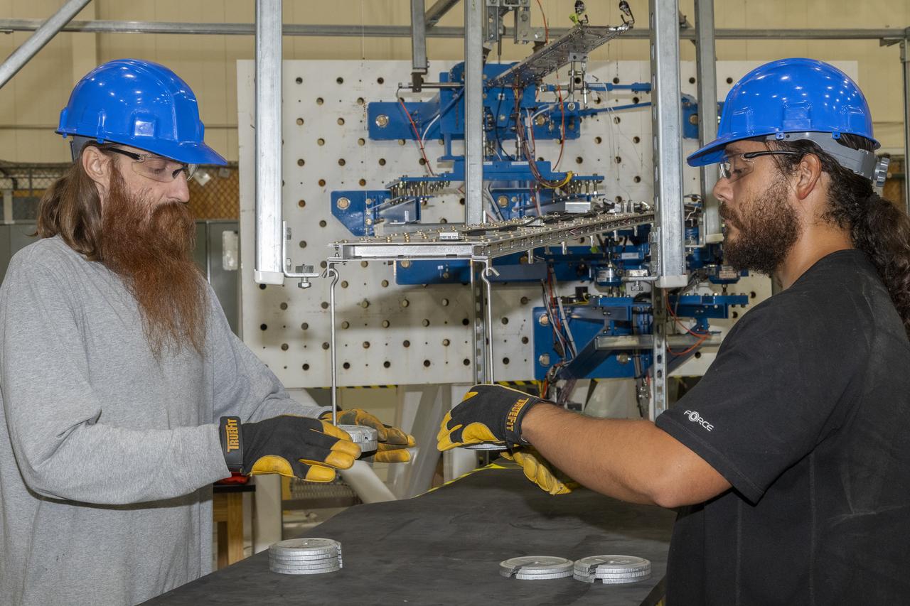
Aaron Rumsey and Beto Hinojos carefully add weight to a 6-foot model of the Transonic Truss-Braced Wing at NASA’s Armstrong Flight Research Center, in Edwards, California. The aircraft concept involves a wing braced on an aircraft using diagonal struts that also add lift and could result in significantly improved aerodynamics.
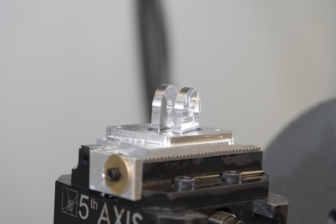
A jury strut adaptor is created for a 10-foot model of the Transonic Truss-Braced Wing at NASA’s Armstrong Flight Research Center, in Edwards, California. The aircraft concept involves a wing braced on an aircraft using diagonal struts that also add lift and could result in significantly improved aerodynamics.
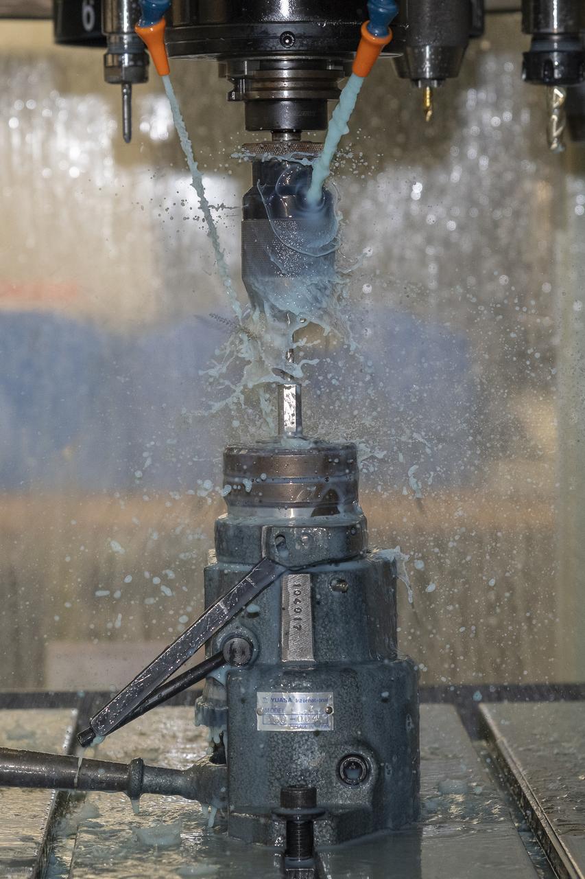
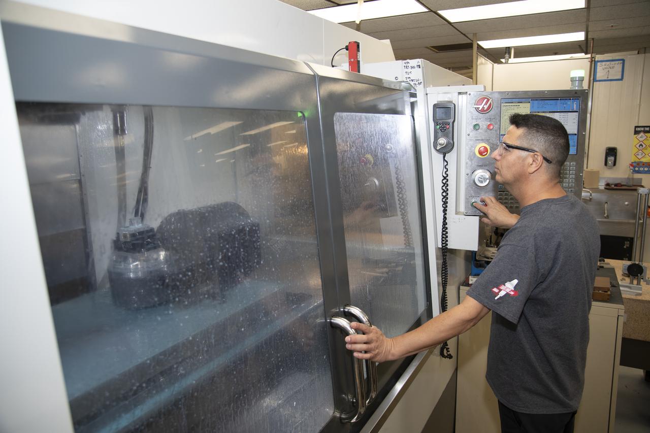
A milling machine drills holes in the strut frame assembly for a 10-foot model of the Transonic Truss-Braced Wing at NASA’s Armstrong Flight Research Center, in Edwards, California. The aircraft concept involves a wing braced on an aircraft using diagonal struts that also add lift and could result in significantly improved aerodynamics.
Researchers test a 10-foot Mock Truss-Braced Wing at NASA’s Armstrong Flight Research Center in Edwards, California. The aircraft concept involves a wing braced on an aircraft using diagonal struts that also add lift and could result in significantly improved aerodynamics.
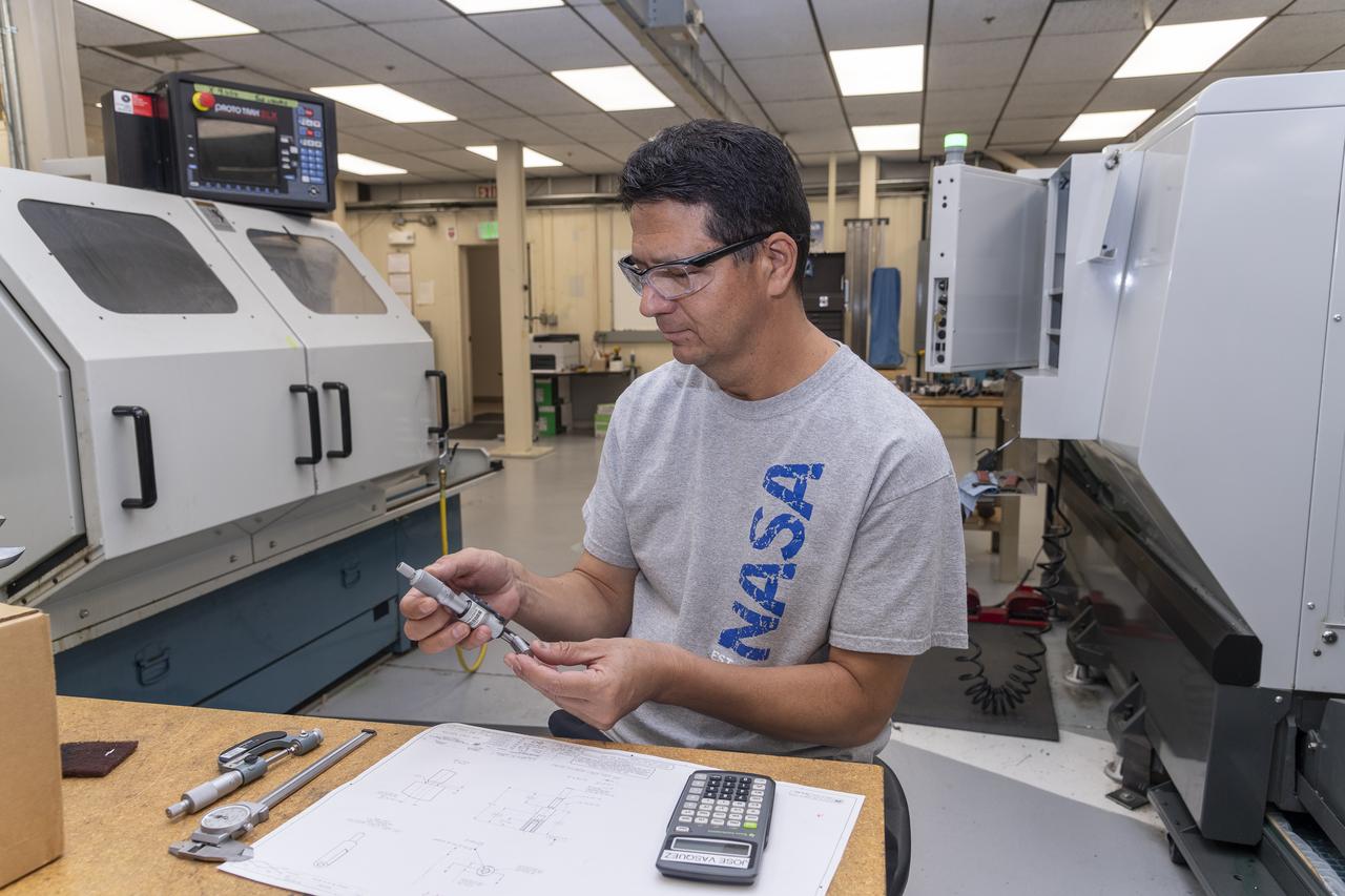
Jose Vasquez verifies a jury strut adaptor created for a 10-foot model of the Transonic Truss-Braced Wing at NASA’s Armstrong Flight Research Center, in Edwards, California. The aircraft concept involves a wing braced on an aircraft using diagonal struts that also add lift and could result in significantly improved aerodynamics.
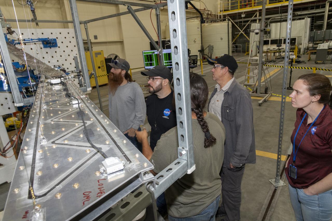
Researchers test a 10-foot Mock Truss-Braced Wing at NASA’s Armstrong Flight Research Center in Edwards, California. The test team makes observations between tests. The aircraft concept involves a wing braced on an aircraft using diagonal struts that also add lift and could result in significantly improved aerodynamics.
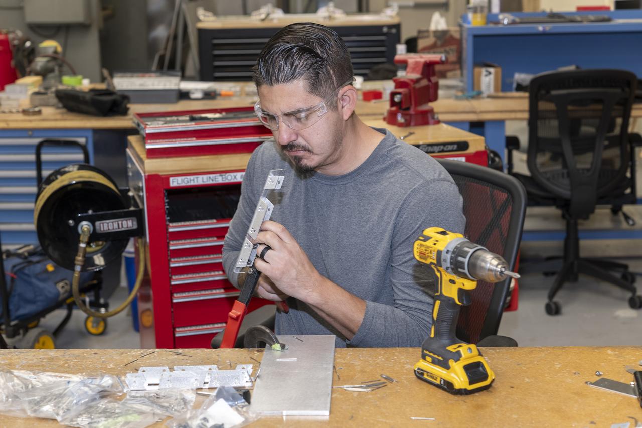
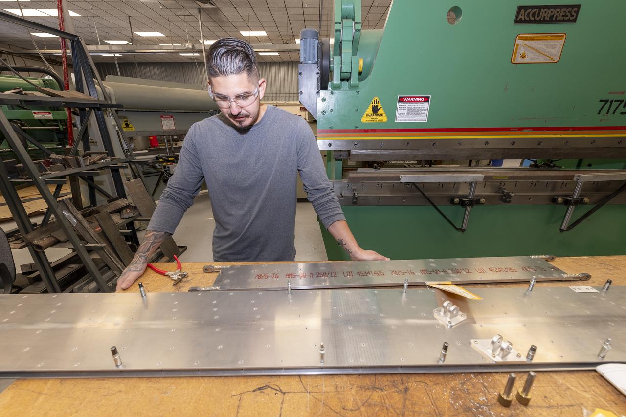
Matthew Sanchez prepares a sheet of aluminum that will be cut into the outer layer of the strut for the 10-foot model of the Transonic Truss-Braced Wing at NASA’s Armstrong Flight Research Center, in Edwards, California. The aircraft concept involves a wing braced on an aircraft using diagonal struts that also add lift and could result in significantly improved aerodynamics.
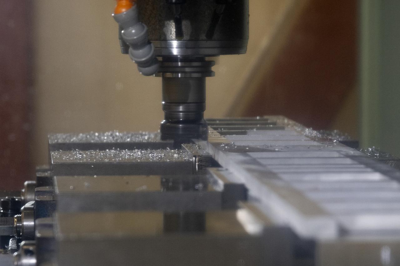
German Escobar works on milling the strut frame assembly for a 10-foot model of the Transonic Truss-Braced Wing at NASA’s Armstrong Flight Research Center, in Edwards, California. The aircraft concept involves a wing braced on an aircraft using diagonal struts that also add lift and could result in significantly improved aerodynamics.
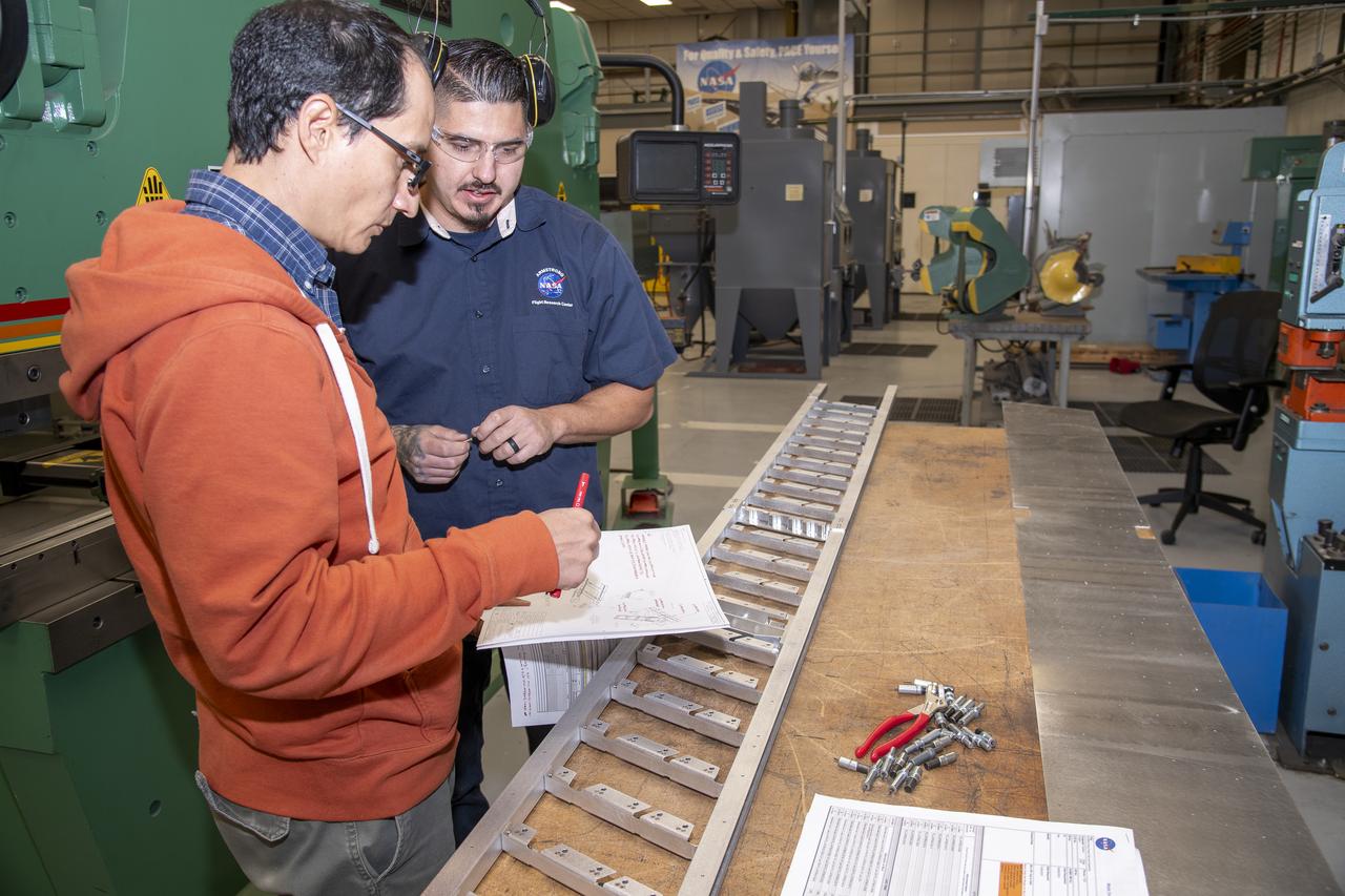
Matthew Sanchez consults with Andrew Holguin on the strut for a 10-foot model of the Transonic Truss-Braced Wing at NASA’s Armstrong Flight Research Center, in Edwards, California. The aircraft concept involves a wing braced on an aircraft using diagonal struts that also add lift and could result in significantly improved aerodynamics.

Researchers test a 10-foot Mock Truss-Braced Wing at NASA’s Armstrong Flight Research Center in Edwards, California. From left, test director Frank Pena and Ray Sadler watch as Lucas Oramas, left, and Charlie Eloff add weight to the test wing to apply stress used to determine its limits. The aircraft concept involves a wing braced on an aircraft using diagonal struts that also add lift and could result in significantly improved aerodynamics.
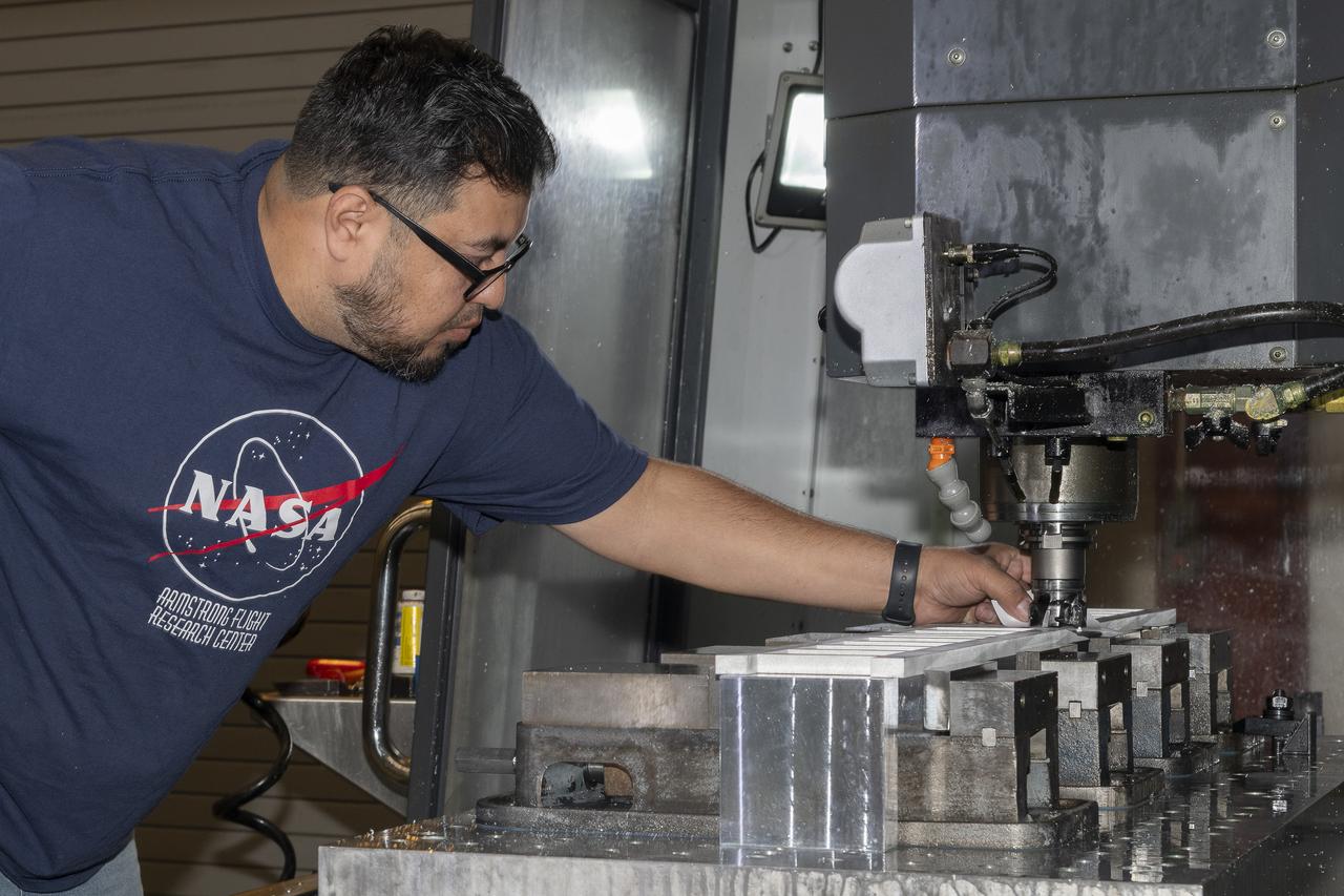
A block of aluminum is transformed by a machine programmed to cut, rotate, and turn it to make a forward wing strut fastener for a 10-foot model of the Transonic Truss-Braced Wing at NASA’s Armstrong Flight Research Center, in Edwards, California. The aircraft concept involves a wing braced on an aircraft using diagonal struts that also add lift and could result in significantly improved aerodynamics.
Jose Vasquez uses a machine to cut, rotate and turn a block of aluminum to make a forward wing strut fastener for a 10-foot model of the Transonic Truss-Braced Wing at NASA’s Armstrong Flight Research Center, in Edwards, California. The aircraft concept involves a wing braced on an aircraft using diagonal struts that also add lift and could result in significantly improved aerodynamics.
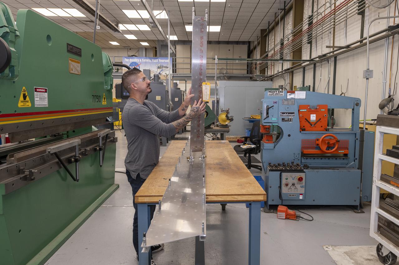
Matthew Sanchez places the strut and the wing side-by-side before assembling them for a check to ensure they fit together as intended for a 10-foot model of the Transonic Truss-Braced Wing at NASA’s Armstrong Flight Research Center, in Edwards, California. The aircraft concept involves a wing braced on an aircraft using diagonal struts that also add lift and could result in significantly improved aerodynamics.
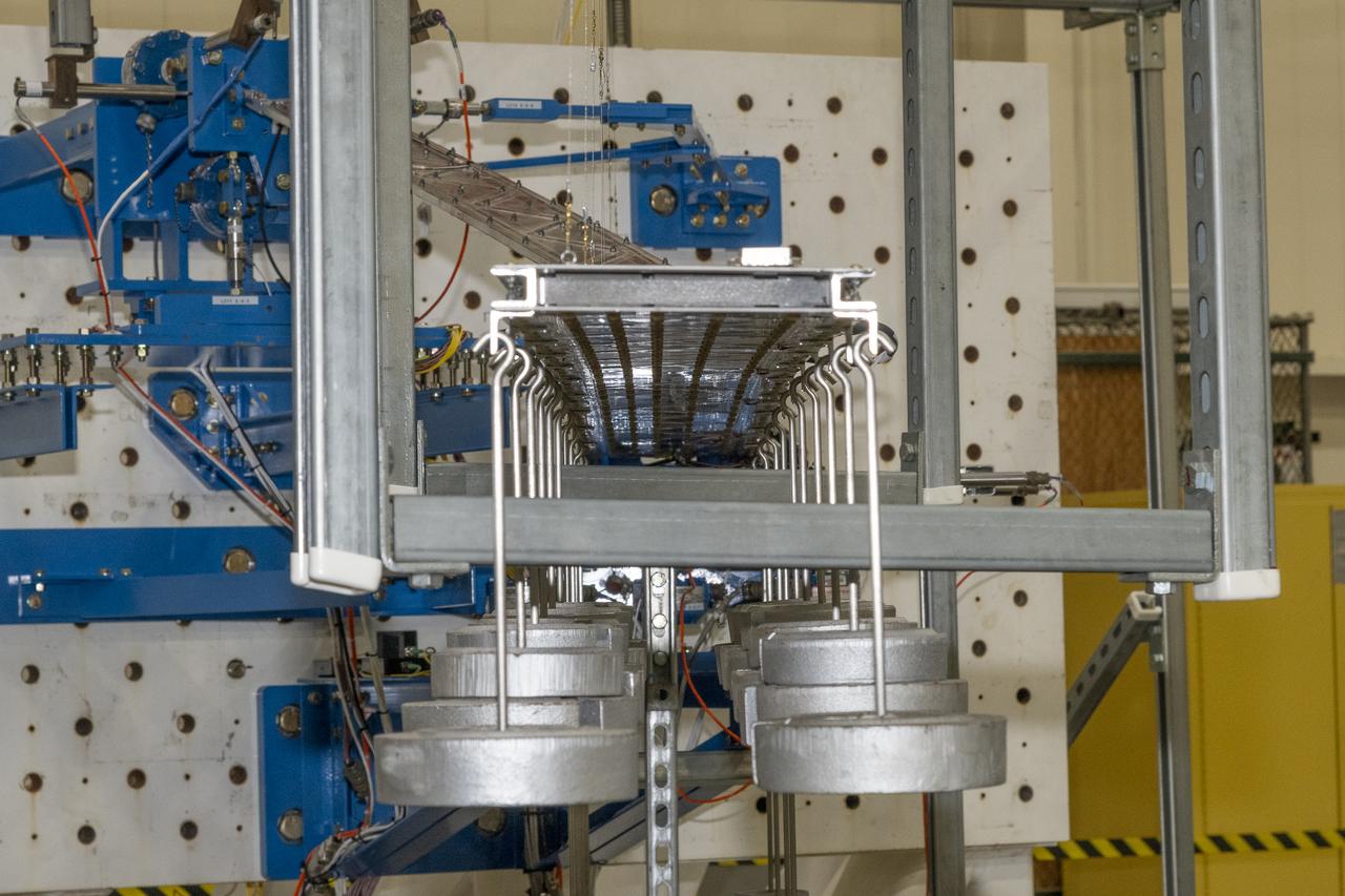
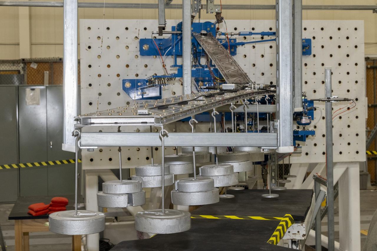
Researchers test a 10-foot Mock Truss-Braced Wing at NASA’s Armstrong Flight Research Center in Edwards, California. Weights are hung from the wing to apply stress used to determine its limits. The aircraft concept involves a wing braced on an aircraft using diagonal struts that also add lift and could result in significantly improved aerodynamics.
Researchers test a 10-foot Mock Truss-Braced Wing at NASA’s Armstrong Flight Research Center in Edwards, California. Charlie Eloff, left, and Lucas Oramas add weight to the test wing to apply stress used to determine its limits. The aircraft concept involves a wing braced on an aircraft using diagonal struts that also add lift and could result in significantly improved aerodynamics.
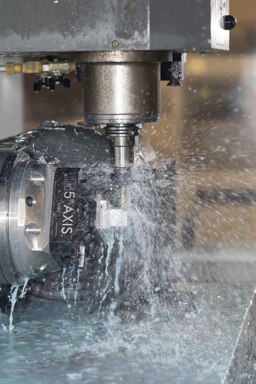
A machine cuts, rotates, and turns a block of aluminum to make a forward wing strut fastener for a 10-foot model of the Transonic Truss-Braced Wing at NASA’s Armstrong Flight Research Center, in Edwards, California. The aircraft concept involves a wing braced on an aircraft using diagonal struts that also add lift and could result in significantly improved aerodynamics.
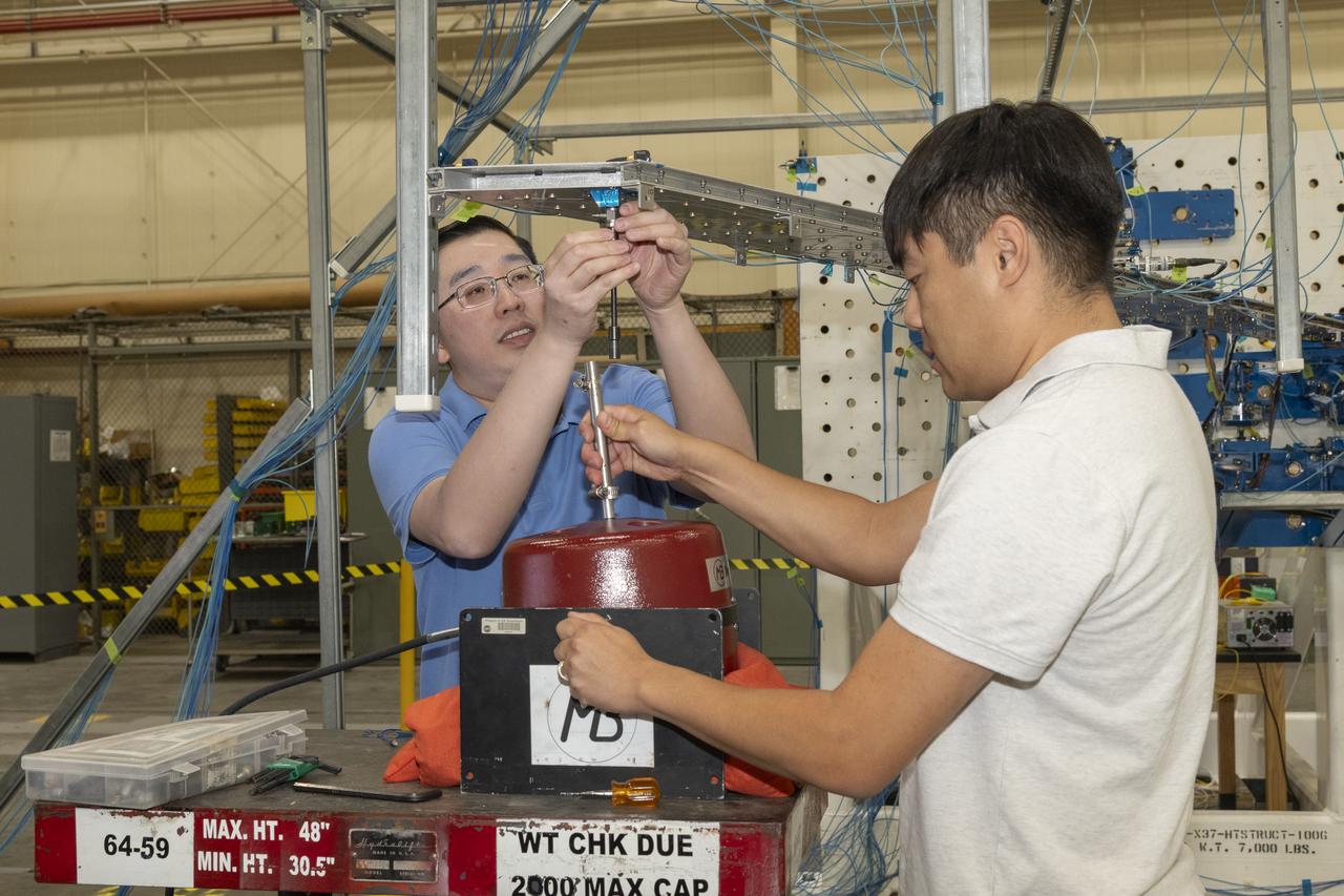
Researchers test a 10-foot Mock Truss-Braced Wing at NASA’s Armstrong Flight Research Center in Edwards, California. Samson Truong, from left, and Ben Park, NASA mock wing ground vibration test director, prepare for a vibration test. The aircraft concept involves a wing braced on an aircraft using diagonal struts that also add lift and could result in significantly improved aerodynamics.
Frank Pena and Benjamin Park watch as data streams in from tests on a 6-foot model of the Transonic Truss-Braced Wing at NASA’s Armstrong Flight Research Center, in Edwards, California.
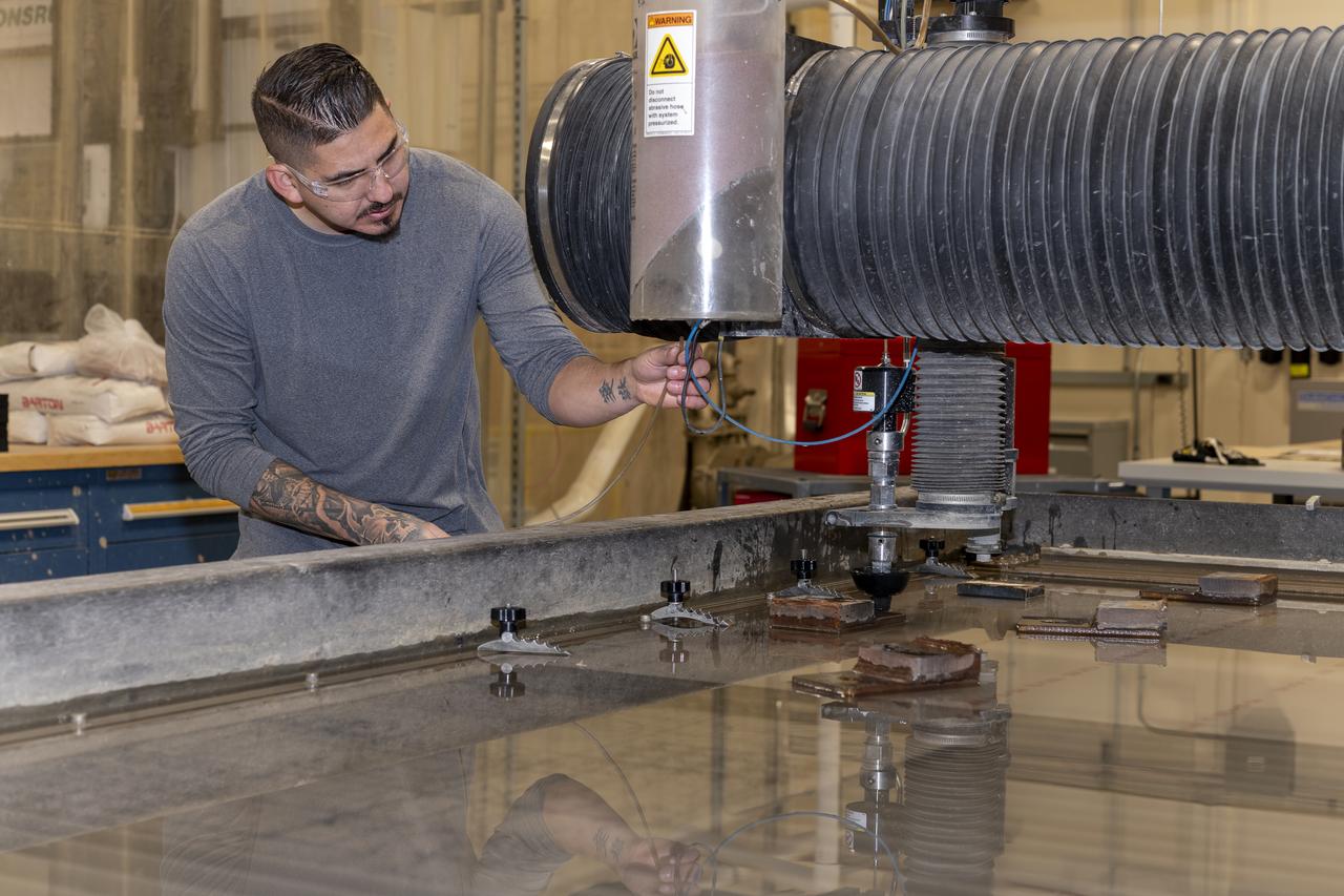
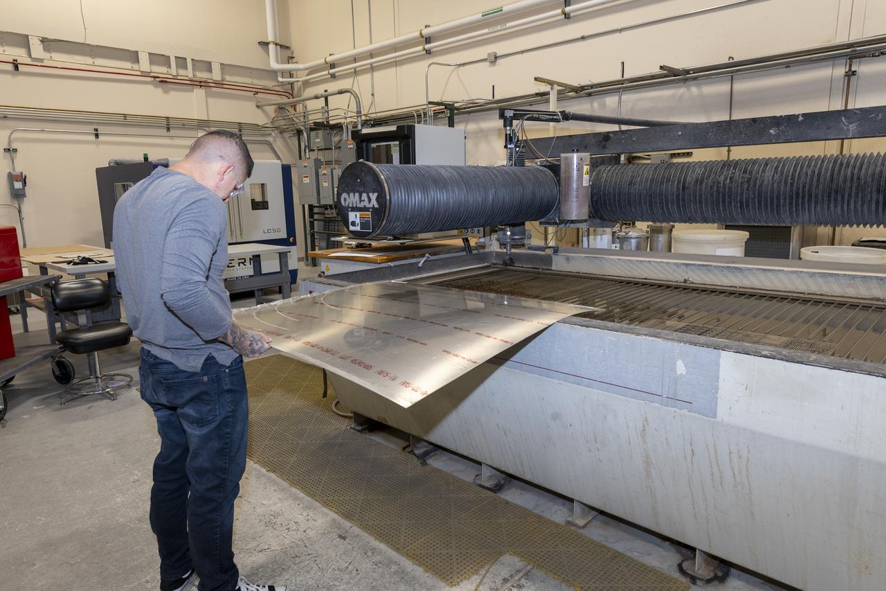
Matthew Sanchez uses a water jet to cut aluminum for the outer layer of the strut for the 10-foot model of the Transonic Truss-Braced Wing at NASA’s Armstrong Flight Research Center, in Edwards, California. The aircraft concept involves a wing braced on an aircraft using diagonal struts that also add lift and could result in significantly improved aerodynamics.

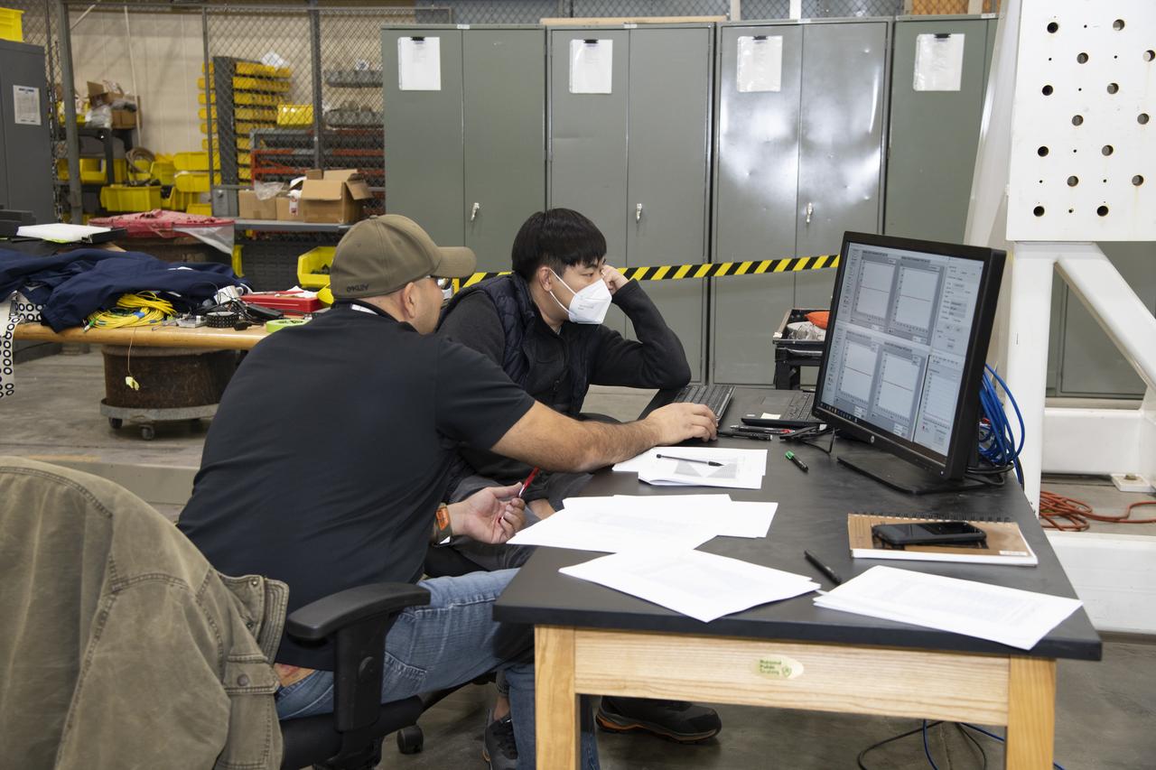
Researchers test a 10-foot Mock Truss-Braced Wing at NASA’s Armstrong Flight Research Center in Edwards, California. Jonathan Lopez, from left, and Jeff Howell watch test data as it is collected. The aircraft concept involves a wing braced on an aircraft using diagonal struts that also add lift and could result in significantly improved aerodynamics.

Jose Vasquez programed a machine to cut, rotate and turn a block of steel to form a jury strut adaptor for a 10-foot model of the Transonic Truss-Braced Wing at NASA’s Armstrong Flight Research Center, in Edwards, California. The aircraft concept involves a wing braced on an aircraft using diagonal struts that also add lift and could result in significantly improved aerodynamics.
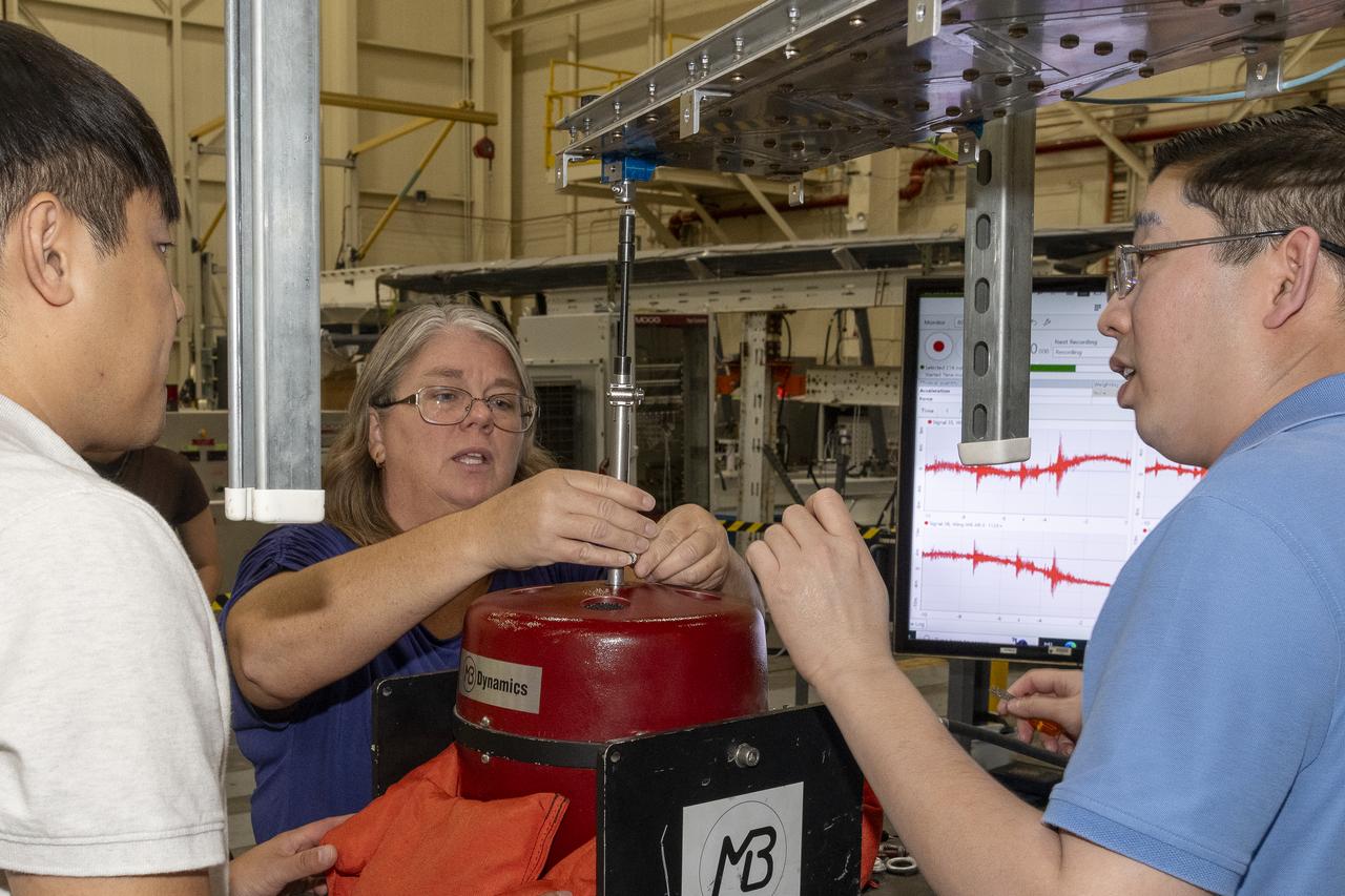
Researchers test a 10-foot Mock Truss-Braced Wing at NASA’s Armstrong Flight Research Center in Edwards, California. From left, ground vibration test director Ben Park, Natalie Spivey, and Samson Truong, prepare for a vibration test. The aircraft concept involves a wing braced on an aircraft using diagonal struts that also add lift and could result in significantly improved aerodynamics.
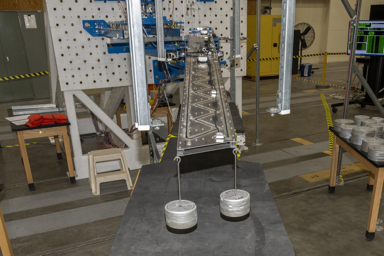
Researchers test a 10-foot Mock Truss-Braced Wing at NASA’s Armstrong Flight Research Center in Edwards, California. Weights are added to the wingtip to apply stress used to determine its limits. The aircraft concept involves a wing braced on an aircraft using diagonal struts that also add lift and could result in significantly improved aerodynamics.
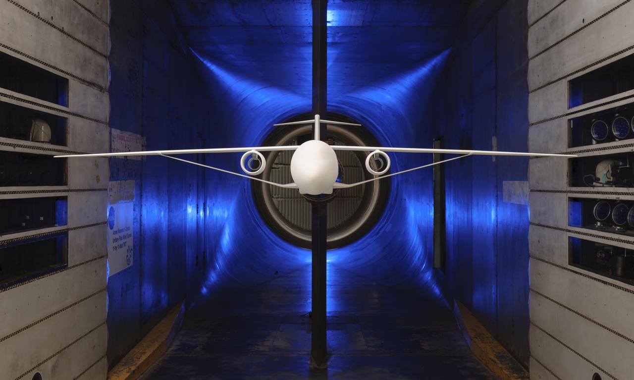
Truss-Braced Wind Model installed in the Ames 11x11 Foot Wind Tunnel for testing. The Truss-Braced model is part of the Subsonic Ultra Green Aircraft Research Project (SUGAR)
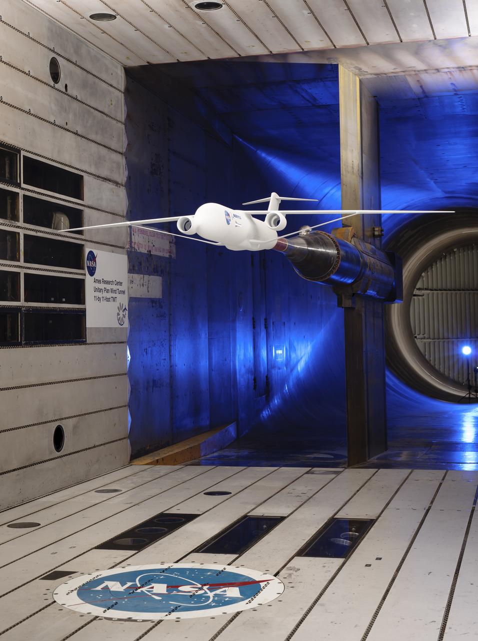
Truss-braced wind model installed in the Ames 11x11 Foot Wind Tunnel for testing as part of the Subsonic Ultra Green Aircraft Research Project (SUGAR)
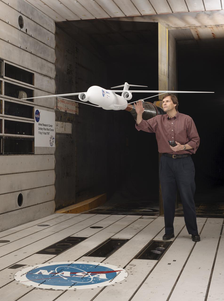
Truss-braced wind model installed in the Ames 11x11 Foot Wind Tunnel for testing as part of the Subsonic Ultra Green Aircraft Research Project (SUGAR) Shown here with test engineer Greg Gatlin, Langley Research Center.
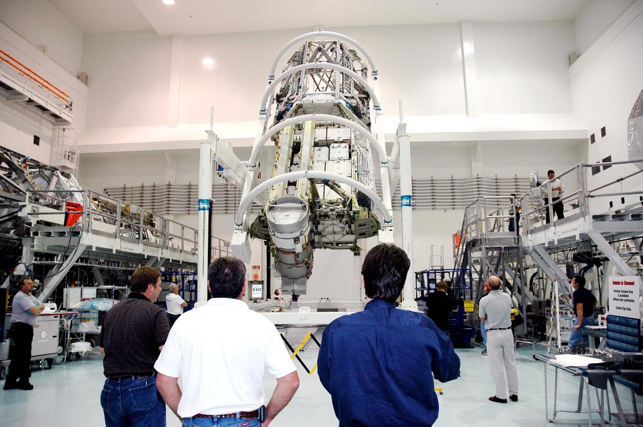
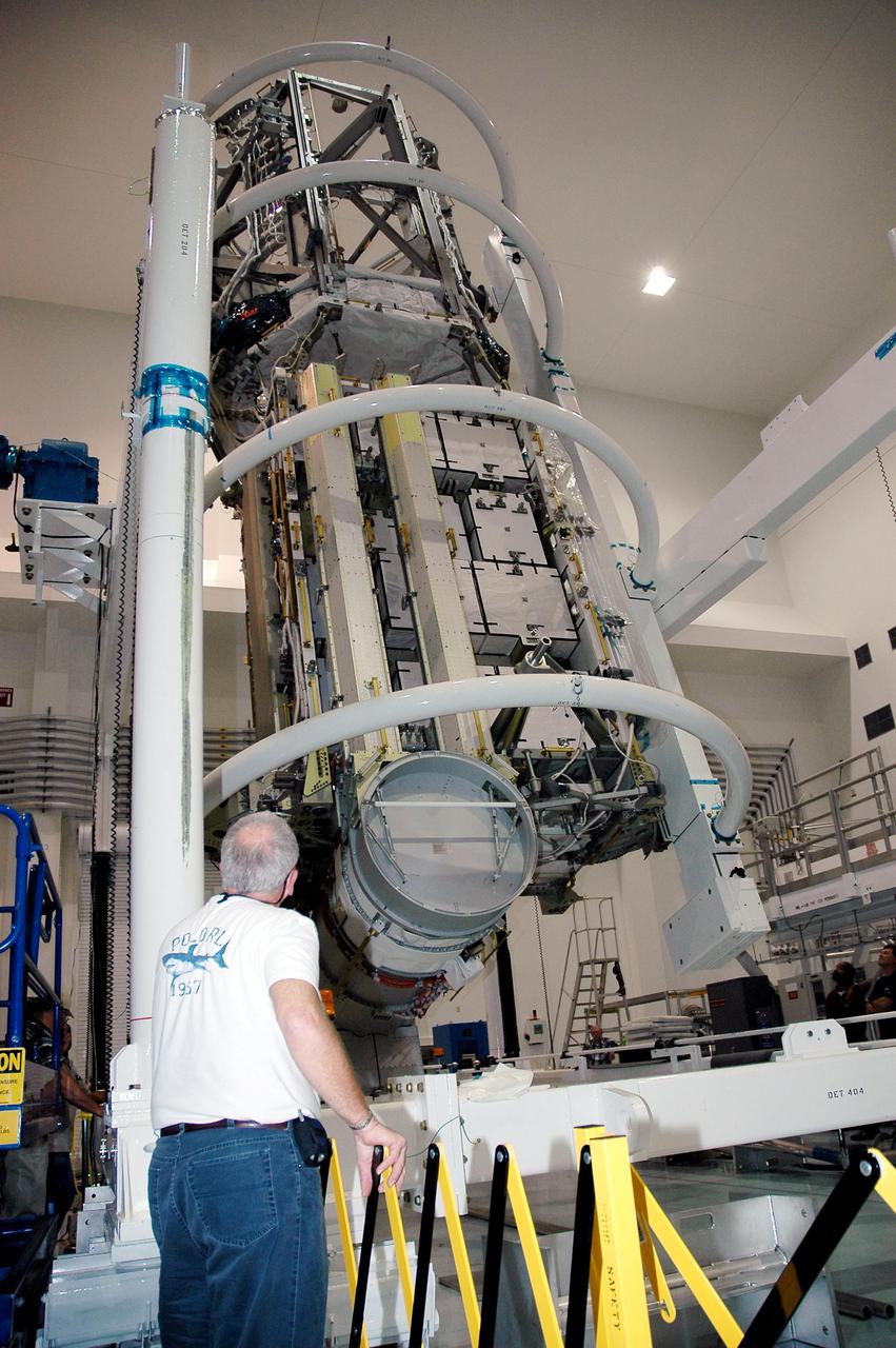
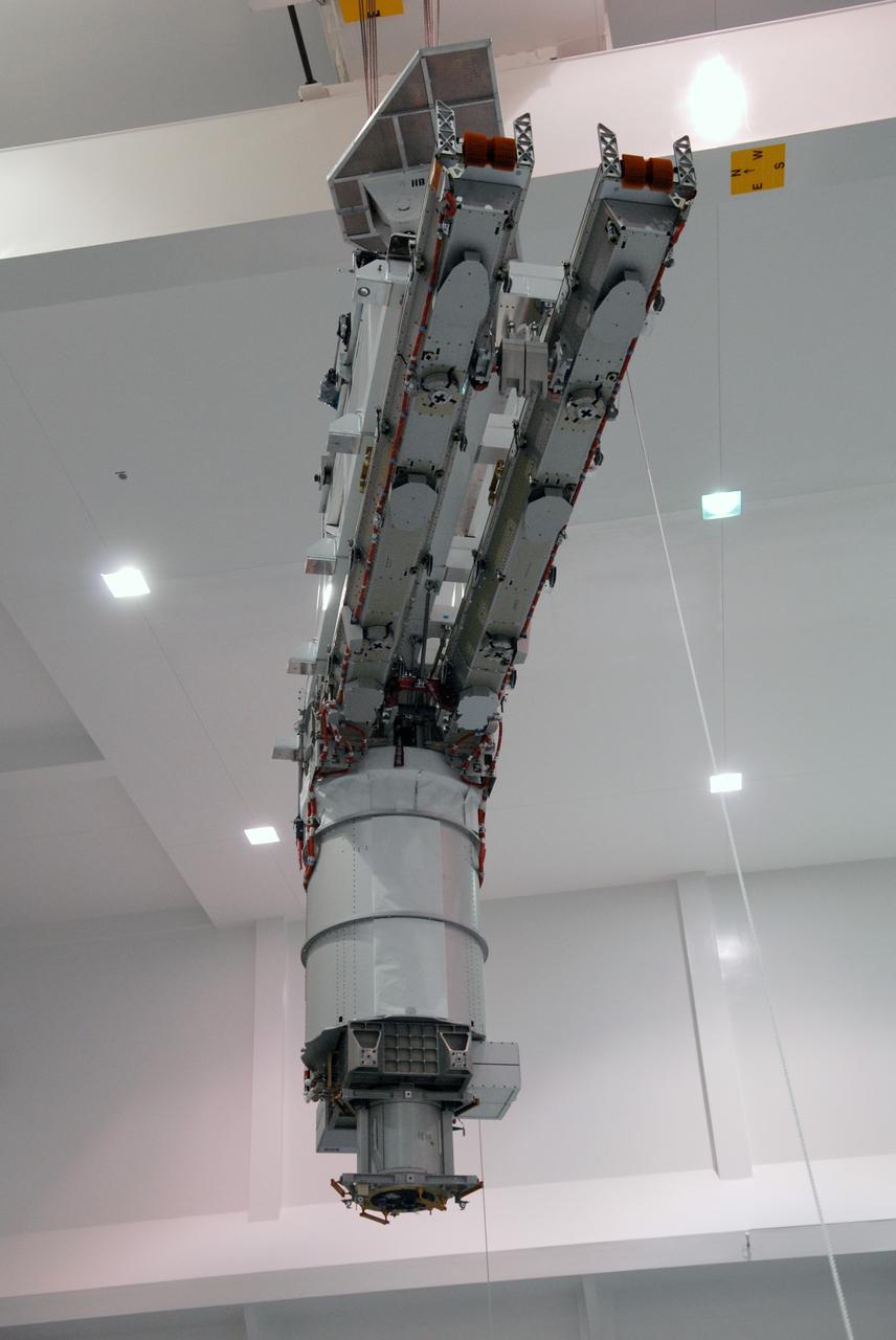
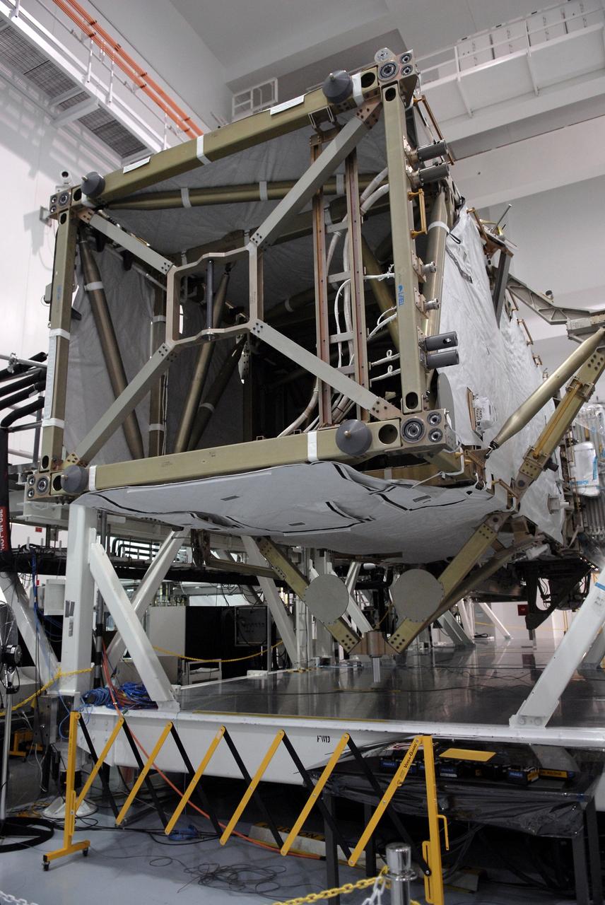
KENNEDY SPACE CENTER, FLA. -In the Space Station Processing Facility at NASA’s Kennedy Space Center, the P3_P4 Truss is rotated to the upper deck position in preparation for installation of the upper deck solar array wing. The truss is scheduled to launch on mission 12A, STS-115, to the International Space Station. The wing was removed to replace aging flight batteries. New batteries are being installed to ensure that the batteries do not exceed their lifetime expectancy prior to their planned logistics resupply on-orbit. The new batteries have a lifetime expectancy of approximately 7 years.
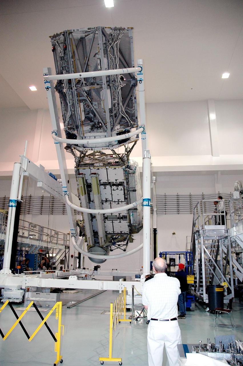
KENNEDY SPACE CENTER, FLA. - In the Space Station Processing Facility at NASA’s Kennedy Space Center, the P3_P4 Truss is rotated to the upper deck position in preparation for installation of the upper deck solar array wing. The truss is scheduled to launch on mission 12A, STS-115, to the International Space Station. The wing was removed to replace aging flight batteries. New batteries are being installed to ensure that the batteries do not exceed their lifetime expectancy prior to their planned logistics resupply on-orbit. The new batteries have a lifetime expectancy of approximately 7 years.
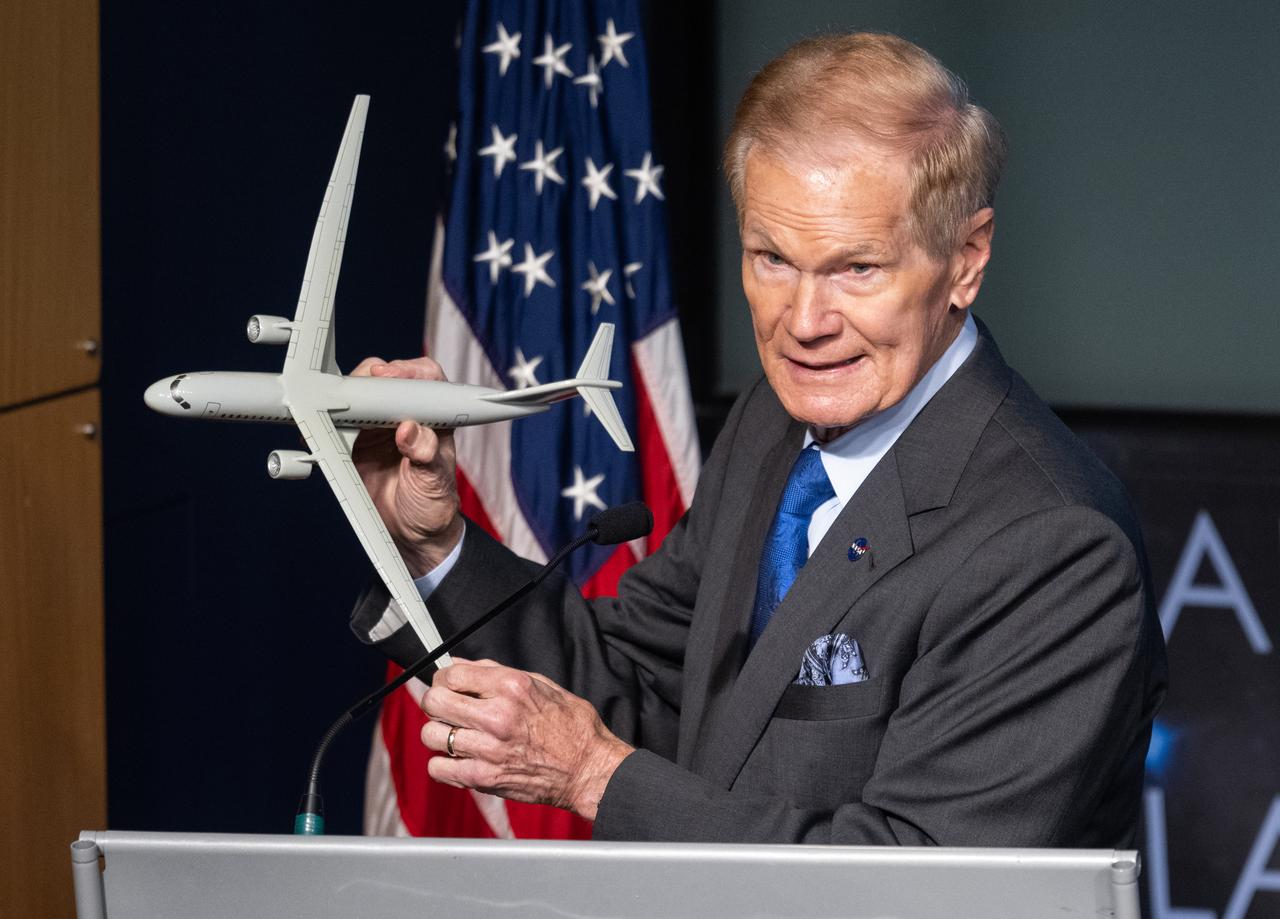
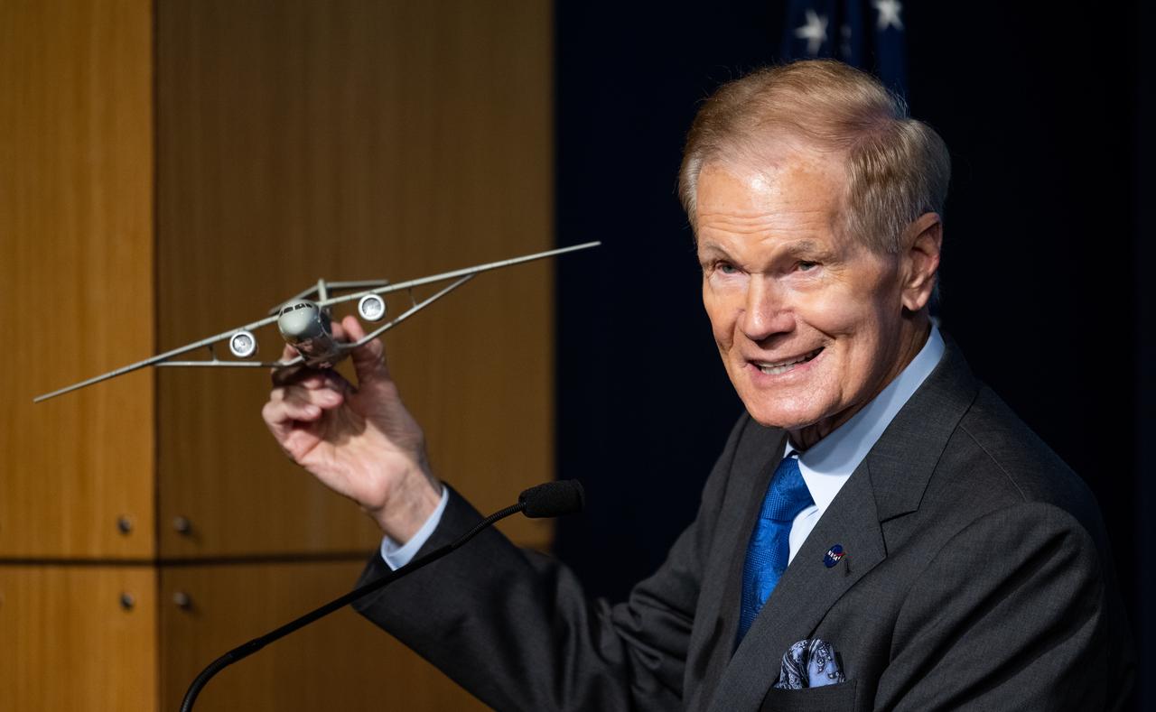
NASA Administrator Bill Nelson holds a model of an aircraft with a Transonic Truss-Braced Wing during a news conference on NASA’s Sustainable Flight Demonstrator project, Wednesday, Jan. 18, 2023, at the Mary W. Jackson NASA Headquarters building in Washington, DC. Through a Funded Space Act Agreement, The Boeing company and its industry team will collaborate with NASA to develop and flight-test a full-scale Transonic Truss-Braced Wing demonstrator aircraft. Photo Credit: (NASA/Joel Kowsky)
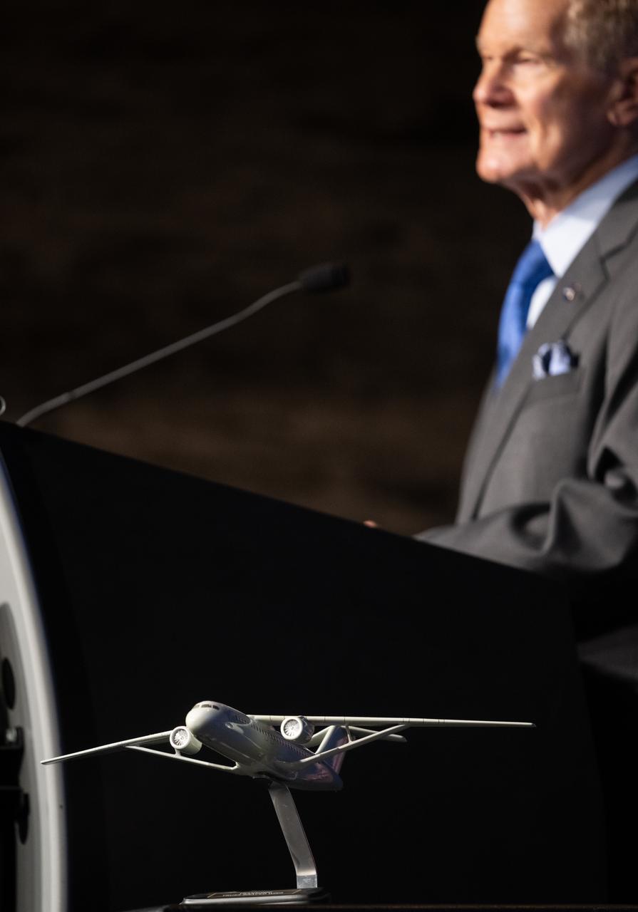
A model of an aircraft with a Transsonic Truss-Braced Wing is seen during a news conference on NASA’s Sustainable Flight Demonstrator project, Wednesday, Jan. 18, 2023, at the Mary W. Jackson NASA Headquarters building in Washington, DC. Through a Funded Space Act Agreement, The Boeing company and its industry team will collaborate with NASA to develop and flight-test a full-scale Transonic Truss-Braced Wing demonstrator aircraft. Photo Credit: (NASA/Joel Kowsky)
NASA Administrator Bill Nelson holds a model of an aircraft with a Transonic Truss-Braced Wing during a news conference on NASA’s Sustainable Flight Demonstrator project, Wednesday, Jan. 18, 2023, at the Mary W. Jackson NASA Headquarters building in Washington, DC. Through a Funded Space Act Agreement, The Boeing company and its industry team will collaborate with NASA to develop and flight-test a full-scale Transonic Truss-Braced Wing demonstrator aircraft. Photo Credit: (NASA/Joel Kowsky)
KENNEDY SPACE CENTER, FLA. - In the Space Station Processing Facility at NASA’s Kennedy Space Center, the P3_P4 Truss is rotated to the upper deck position in preparation for installation of the upper deck solar array wing. The truss is scheduled to launch on mission 12A, STS-115, to the International Space Station. The wing was removed to replace aging flight batteries. New batteries are being installed to ensure that the batteries do not exceed their lifetime expectancy prior to their planned logistics resupply on-orbit. The new batteries have a lifetime expectancy of approximately 7 years.
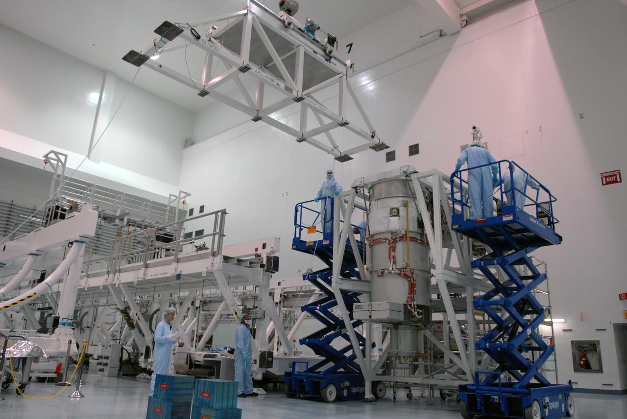
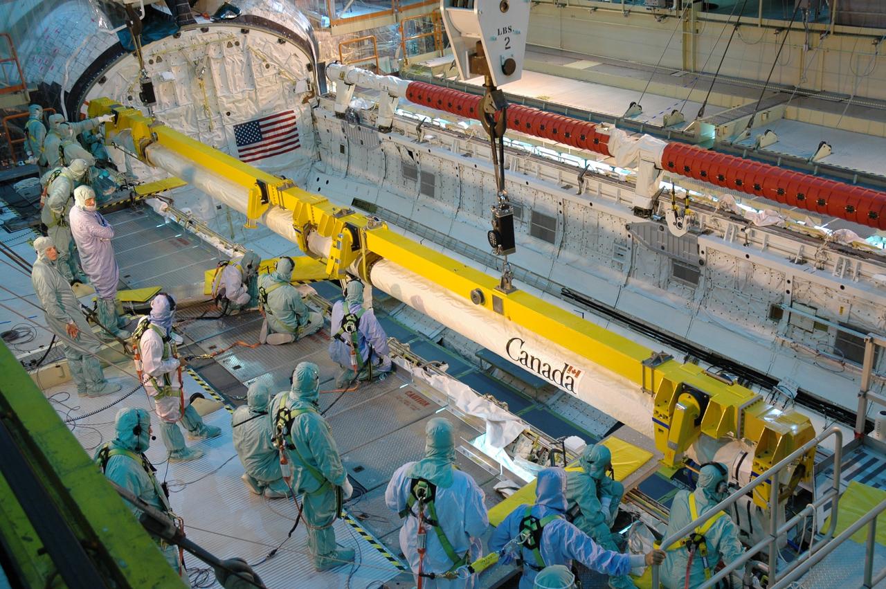
CAPE CANAVERAL, Fla. – In the Space Station Processing Facility at NASA's Kennedy Space Center, workers prepare to install the final solar array wing for the International Space Station onto the S6 truss element. Scheduled to launch on the STS-119 mission, space shuttle Discovery will carry the S6 truss segment to complete the 361-foot-long backbone of the International Space Station. The truss includes the fourth pair of solar array wings and electronics that convert sunlight to power for the orbiting laboratory. Launch is targeted for Feb. 12, 2009. Photo credit: NASA/Troy Cryder
CAPE CANAVERAL, Fla. – In the Space Station Processing Facility at NASA's Kennedy Space Center, workers move the final solar array wing for the International Space Station into position for installation on the S6 truss element. Scheduled to launch on the STS-119 mission, space shuttle Discovery will carry the S6 truss segment to complete the 361-foot-long backbone of the International Space Station. The truss includes the fourth pair of solar array wings and electronics that convert sunlight to power for the orbiting laboratory. Launch is targeted for Feb. 12, 2009. Photo credit: NASA/Troy Cryder
CAPE CANAVERAL, Fla. – In the Space Station Processing Facility at NASA's Kennedy Space Center, the final solar array wing for the International Space Station is moved into position for installation onto the S6 truss element. Scheduled to launch on the STS-119 mission, space shuttle Discovery will carry the S6 truss segment to complete the 361-foot-long backbone of the International Space Station. The truss includes the fourth pair of solar array wings and electronics that convert sunlight to power for the orbiting laboratory. Launch is targeted for Feb. 12, 2009. Photo credit: NASA/Troy Cryder

CAPE CANAVERAL, Fla. – In the Space Station Processing Facility at NASA's Kennedy Space Center, workers install the final solar array wing for the International Space Station onto the S6 truss element. Scheduled to launch on the STS-119 mission, space shuttle Discovery will carry the S6 truss segment to complete the 361-foot-long backbone of the International Space Station. The truss includes the fourth pair of solar array wings and electronics that convert sunlight to power for the orbiting laboratory. Launch is targeted for Feb. 12, 2009. Photo credit: NASA/Troy Cryder
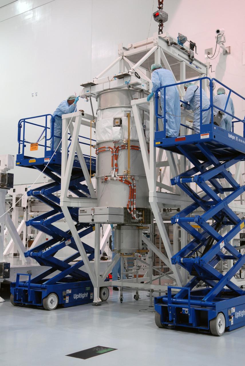
CAPE CANAVERAL, Fla. – In the Space Station Processing Facility at NASA's Kennedy Space Center, workers prepare to move the final solar array wing for the International Space Station for installation on the S6 truss element. Scheduled to launch on the STS-119 mission, space shuttle Discovery will carry the S6 truss segment to complete the 361-foot-long backbone of the International Space Station. The truss includes the fourth pair of solar array wings and electronics that convert sunlight to power for the orbiting laboratory. Launch is targeted for Feb. 12, 2009. Photo credit: NASA/Troy Cryder
KENNEDY SPACE CENTER, FLA. - In the Space Station Processing Facility at NASA’s Kennedy Space Center, the P3_P4 Truss is prepared to be rotated to the upper deck position in preparation for installation of the upper deck solar array wing. The truss is scheduled to launch on mission 12A, STS-115, to the International Space Station. The wing was removed to replace aging flight batteries. New batteries are being installed to ensure that the batteries do not exceed their lifetime expectancy prior to their planned logistics resupply on-orbit. The new batteries have a lifetime expectancy of approximately 7 years.
KENNEDY SPACE CENTER, FLA. - In the Space Station Processing Facility at NASA’s Kennedy Space Center, the P3_P4 Truss is being prepared to be rotated to the upper deck position in preparation for installation of the upper deck solar array wing. The truss is scheduled to launch on mission 12A, STS-115, to the International Space Station. The wing was removed to replace aging flight batteries. New batteries are being installed to ensure that the batteries do not exceed their lifetime expectancy prior to their planned logistics resupply on-orbit. The new batteries have a lifetime expectancy of approximately 7 years.
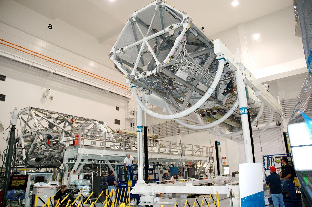
KENNEDY SPACE CENTER, FLA. - In the Space Station Processing Facility at NASA’s Kennedy Space Center, the P3_P4 Truss has been rotated to the upper deck position in preparation for installation of the upper deck solar array wing. The truss is scheduled to launch on mission 12A, STS-115, to the International Space Station. The wing was removed to replace aging flight batteries. New batteries are being installed to ensure that the batteries do not exceed their lifetime expectancy prior to their planned logistics resupply on-orbit. The new batteries have a lifetime expectancy of approximately 7 years.
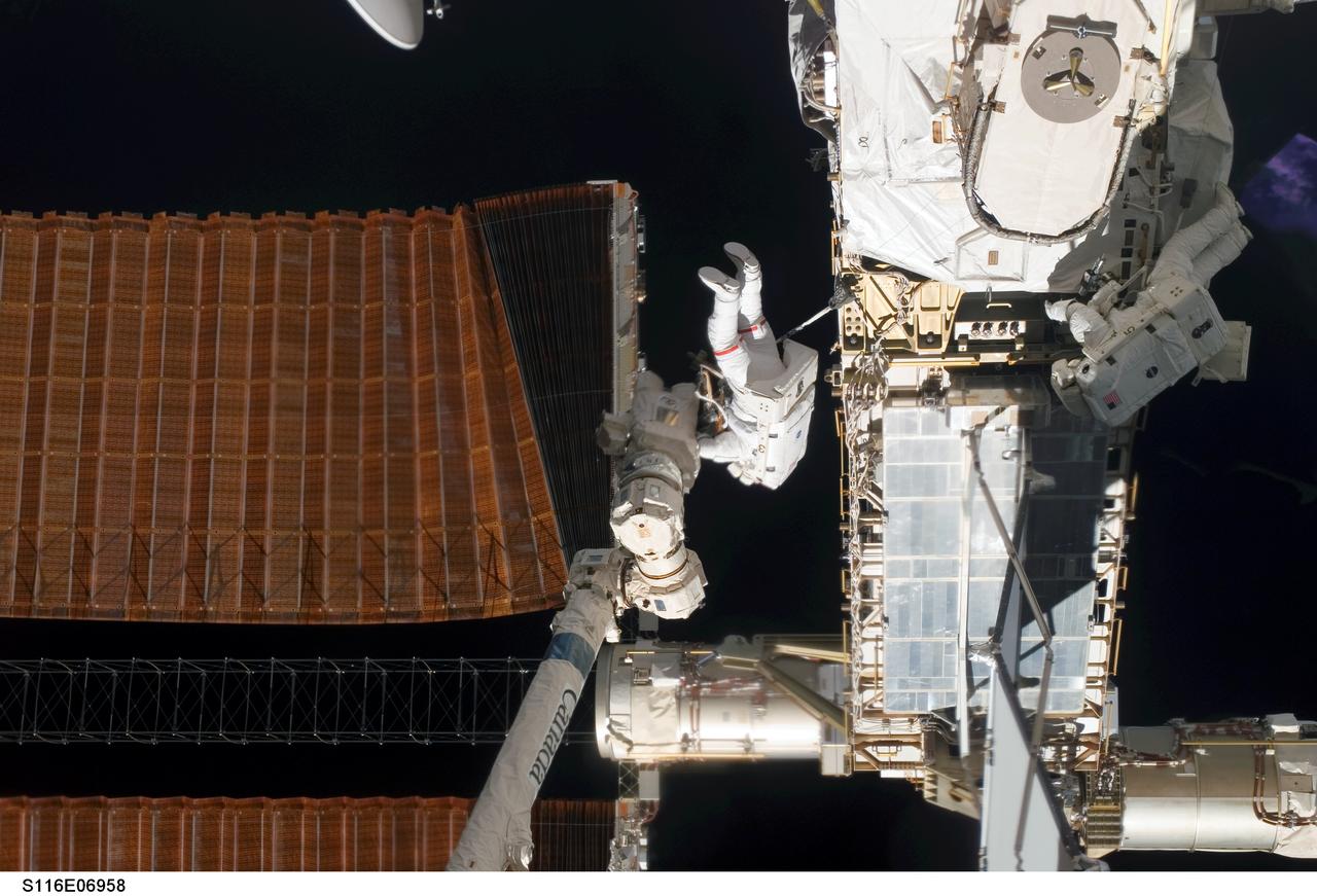
S116-E-06958 (18 Dec. 2006) --- Astronaut Robert L. Curbeam Jr. (center) and European Space Agency (ESA) astronaut Christer Fuglesang (right), both STS-116 mission specialists, work with the port overhead solar array wing on the International Space Station's P6 truss during the mission's fourth session of extravehicular activity (EVA). The spacewalkers used specially-prepared, tape-insulated tools, to guide the array wing neatly inside its blanket box during the 6-hour, 38-minute spacewalk.
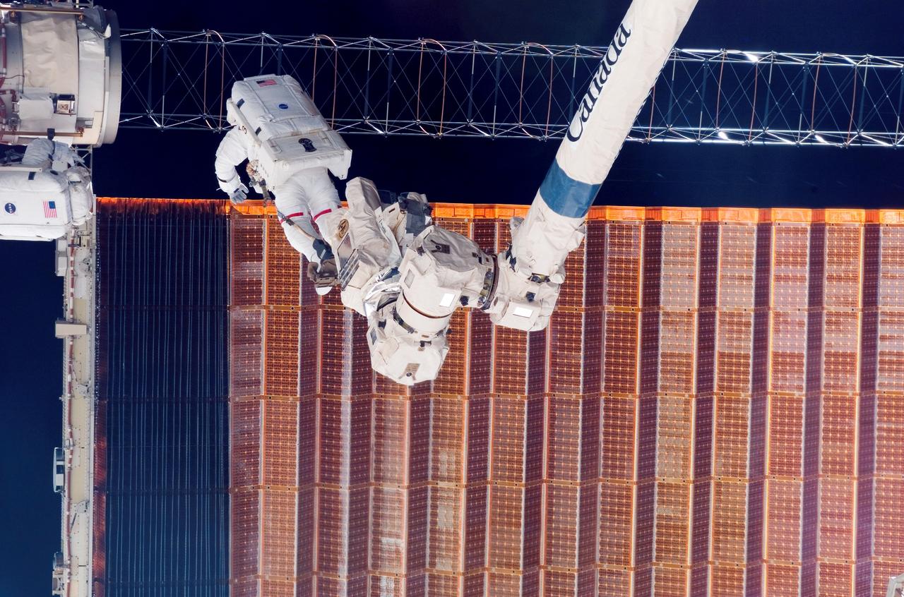
STS-116 astronaut and mission specialist, Robert Curbeam, along with the European Space Agency’s (ESA) Christer Fuglesang (partially out of the frame), are anchored to the International Space Station’s Canadarm2 foot restraints. The two were working on the port overhead solar array wing on the Station’s P6 truss during the mission’s fourth session of Extra Vehicular Activity (EVA). For 6 hours and 38 minutes, the space walkers used specially prepared, tape insulated tools to guide the array wing neatly inside its blanket box.
CAPE CANAVERAL, Fla. – In the Orbiter Processing Facility bay 3, space shuttle Discovery's robotic arm is lowered into the payload bay for installation. Scheduled to launch on the STS-119 mission, Discovery will carry the S6 truss segment to complete the 361-foot-long backbone of the International Space Station. The truss includes the fourth pair of solar array wings and electronics that convert sunlight to power for the orbiting laboratory. A launch date has not yet been determined. Photo credit: NASA/Jim Grossmann
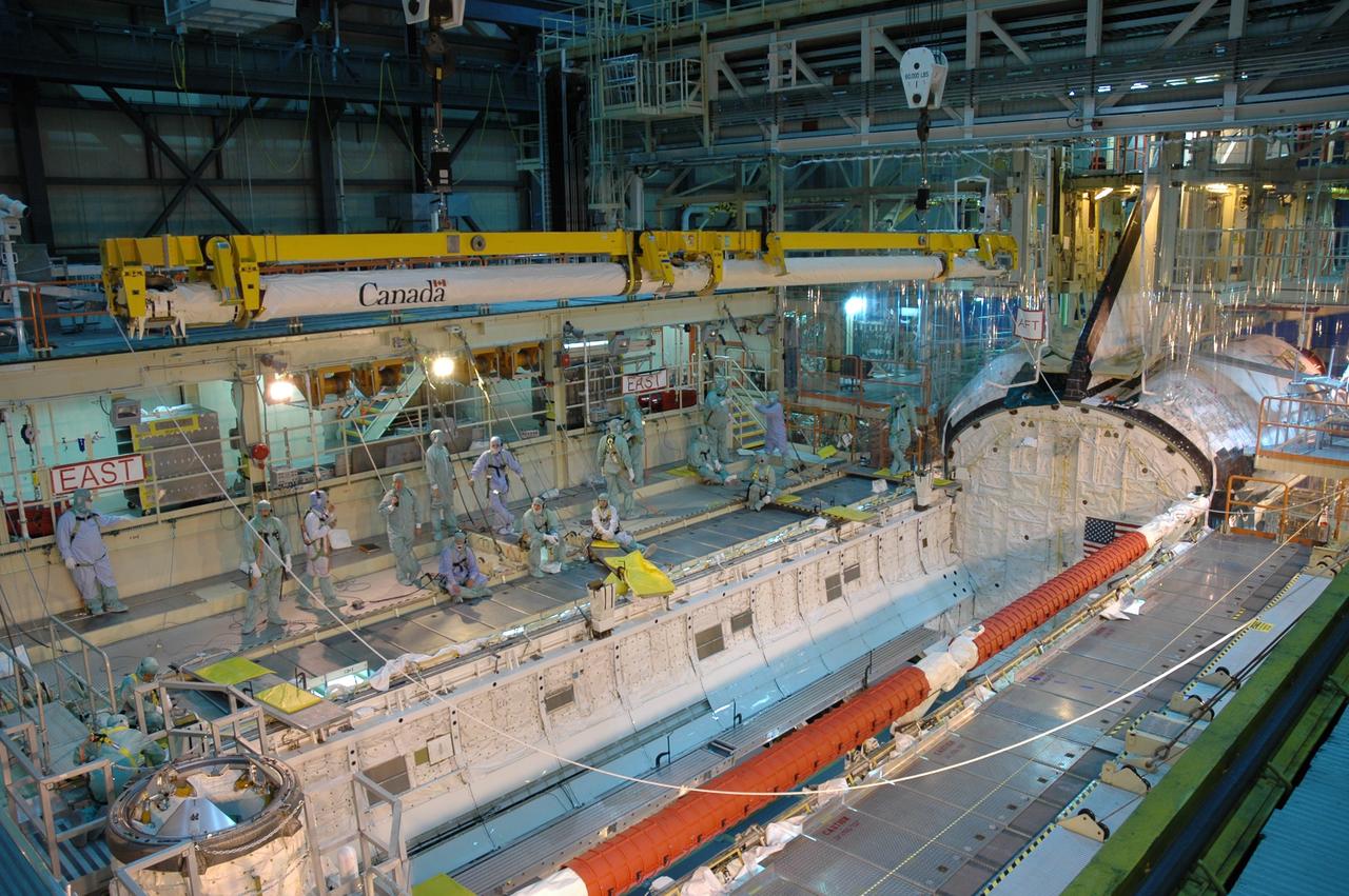
CAPE CANAVERAL, Fla. – In the Orbiter Processing Facility bay 3, space shuttle Discovery's robotic arm (top of photo) is being moved for installation in the shuttle's payload bay. Scheduled to launch on the STS-119 mission, Discovery will carry the S6 truss segment to complete the 361-foot-long backbone of the International Space Station. The truss includes the fourth pair of solar array wings and electronics that convert sunlight to power for the orbiting laboratory. A launch date has not yet been determined. Photo credit: NASA/Jim Grossmann
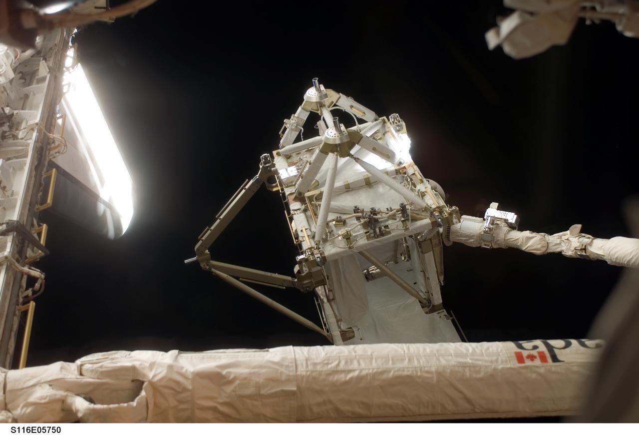
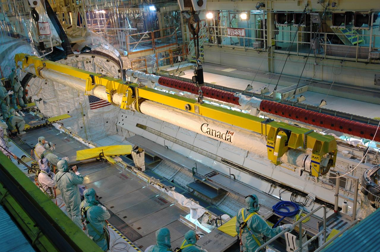
S116-E-05750 (11 Dec. 2006) --- The International Space Station's new P5 truss section is moved out of Space Shuttle Discovery's payload bay by a cabin-bound STS-116 crewmember, using the shuttle's Remote Manipulator System (RMS) robotic arm. The truss section will be handed to the station's Canadarm2 and will remain suspended over Discovery's port wing overnight, awaiting installation in the first of three planned spacewalks on Dec. 12.
CAPE CANAVERAL, Fla. – In the Orbiter Processing Facility bay 3, workers ensure space shuttle Discovery's robotic arm is placed correctly for installation in the payload bay. Scheduled to launch on the STS-119 mission, Discovery will carry the S6 truss segment to complete the 361-foot-long backbone of the International Space Station. The truss includes the fourth pair of solar array wings and electronics that convert sunlight to power for the orbiting laboratory. A launch date has not yet been determined. Photo credit: NASA/Jim Grossmann
CAPE CANAVERAL, Fla. – In the Orbiter Processing Facility bay 3, space shuttle Discovery's robotic arm (top of photo) is being moved for installation in the shuttle's payload bay. Scheduled to launch on the STS-119 mission, Discovery will carry the S6 truss segment to complete the 361-foot-long backbone of the International Space Station. The truss includes the fourth pair of solar array wings and electronics that convert sunlight to power for the orbiting laboratory. A launch date has not yet been determined. Photo credit: NASA/Jim Grossmann

CAPE CANAVERAL, Fla. – In the Orbiter Processing Facility bay 3, space shuttle Discovery's robotic arm is moved into place for installation in the payload bay. Scheduled to launch on the STS-119 mission, Discovery will carry the S6 truss segment to complete the 361-foot-long backbone of the International Space Station. The truss includes the fourth pair of solar array wings and electronics that convert sunlight to power for the orbiting laboratory. A launch date has not yet been determined. Photo credit: NASA/Jim Grossmann
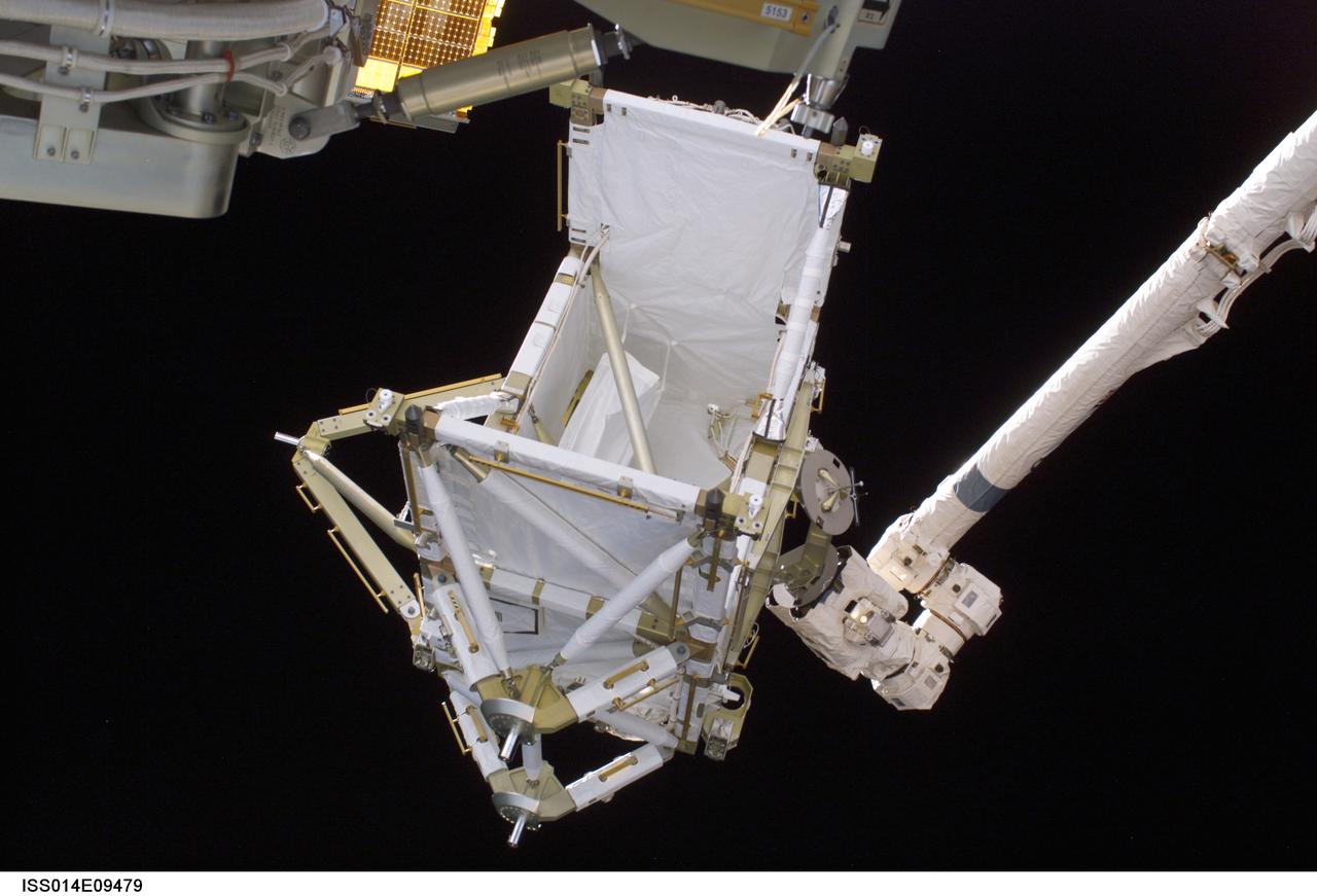
ISS014-E-09479 (12 Dec. 2006) --- The International Space Station's new P5 truss section awaits installation following the hand-off from Space Shuttle Discovery's Remote Manipulator System (RMS) robotic arm. The truss section was handed to the station's Canadarm2 and remained suspended over Discovery's port wing overnight, awaiting installation in the first of three planned spacewalks on Dec. 12.
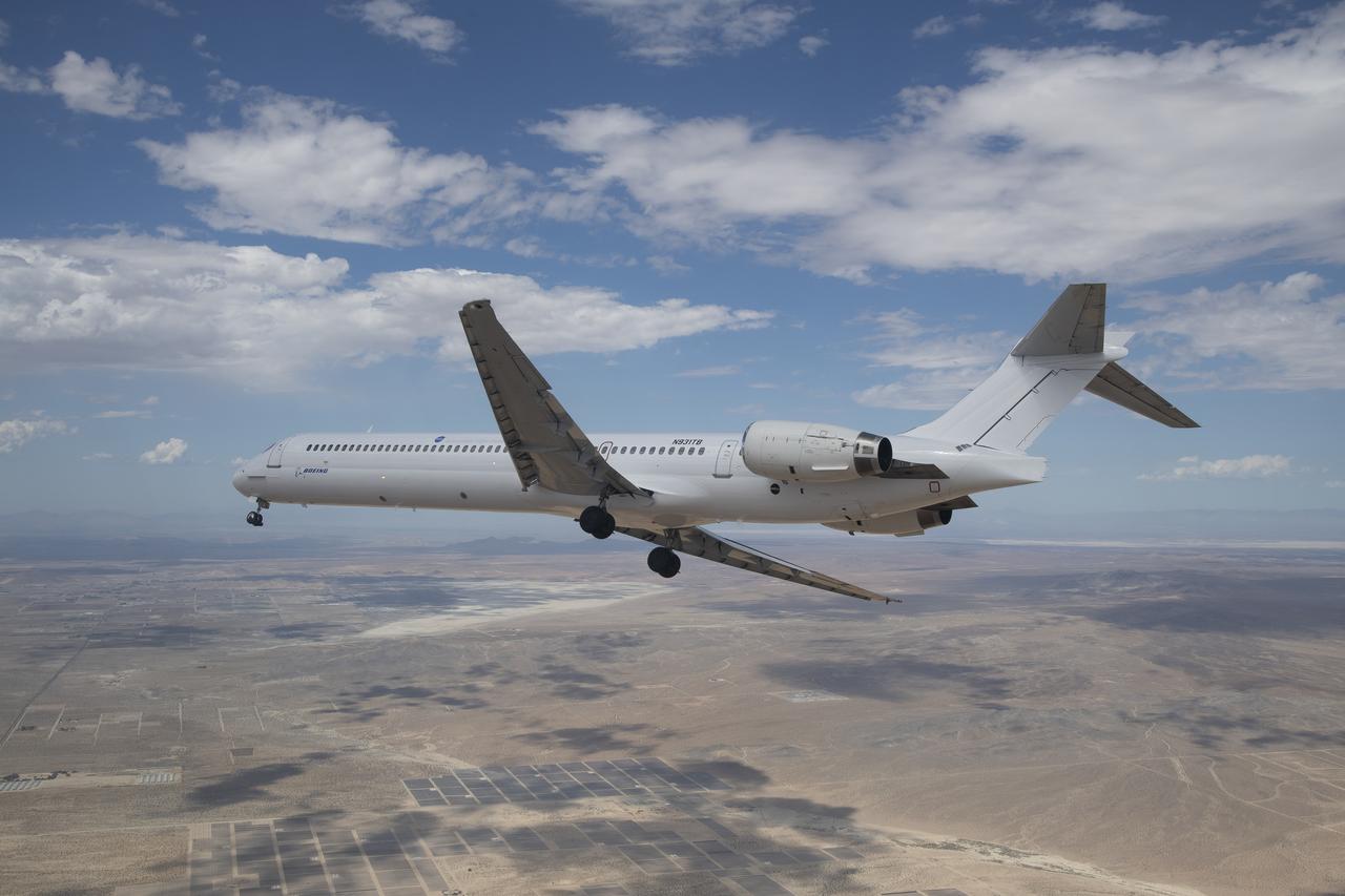
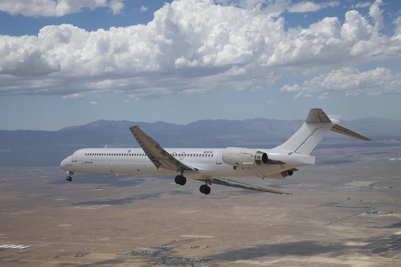
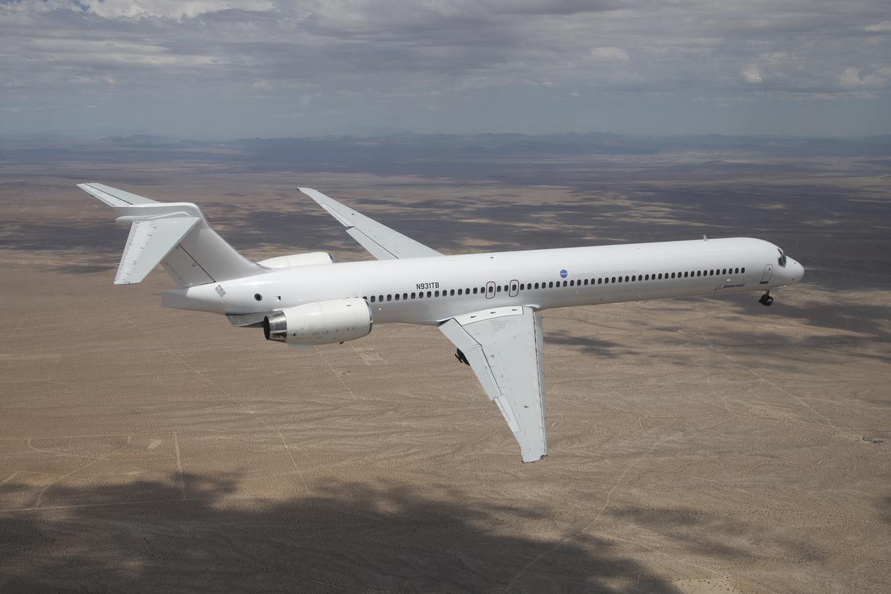
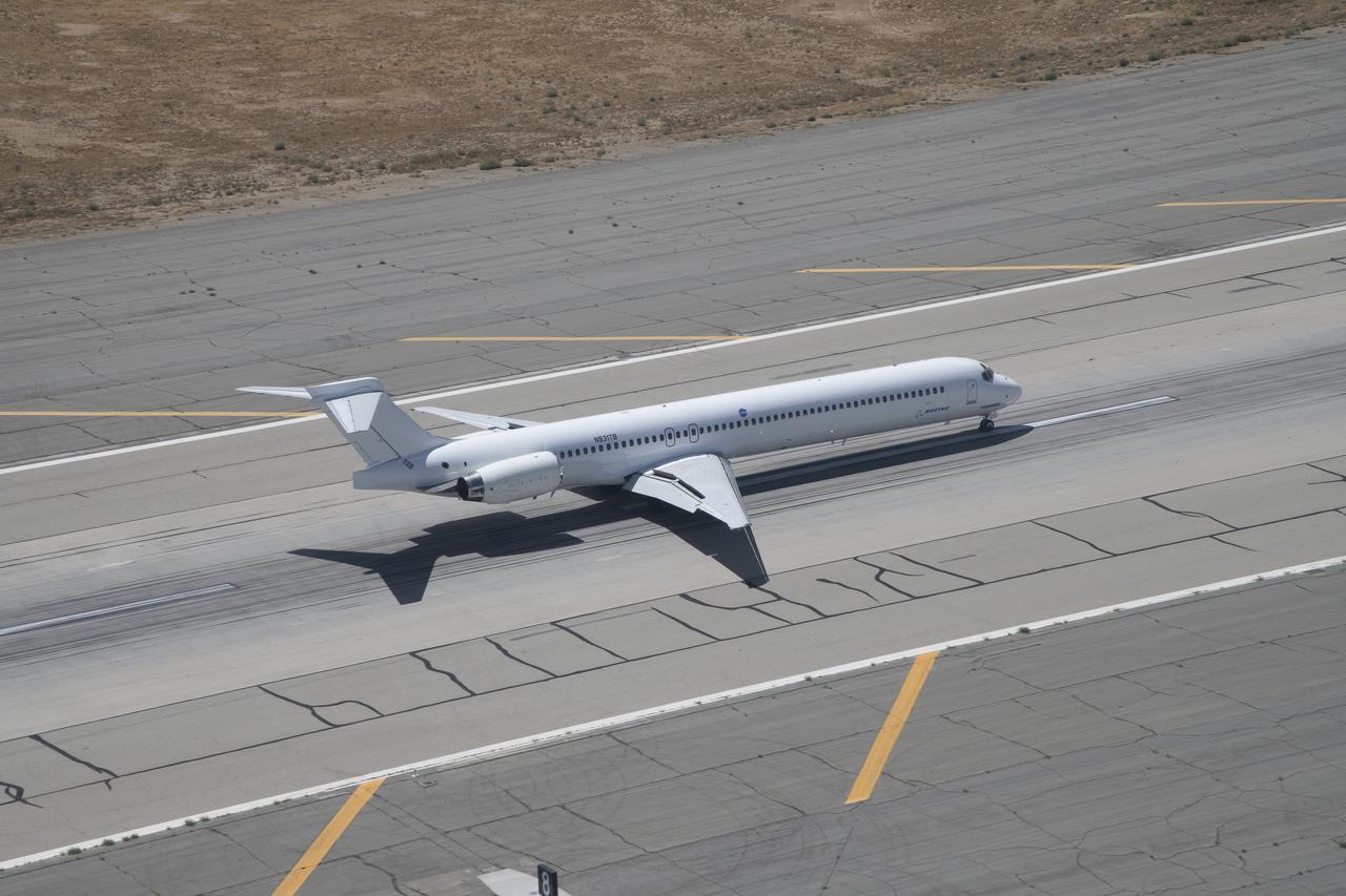
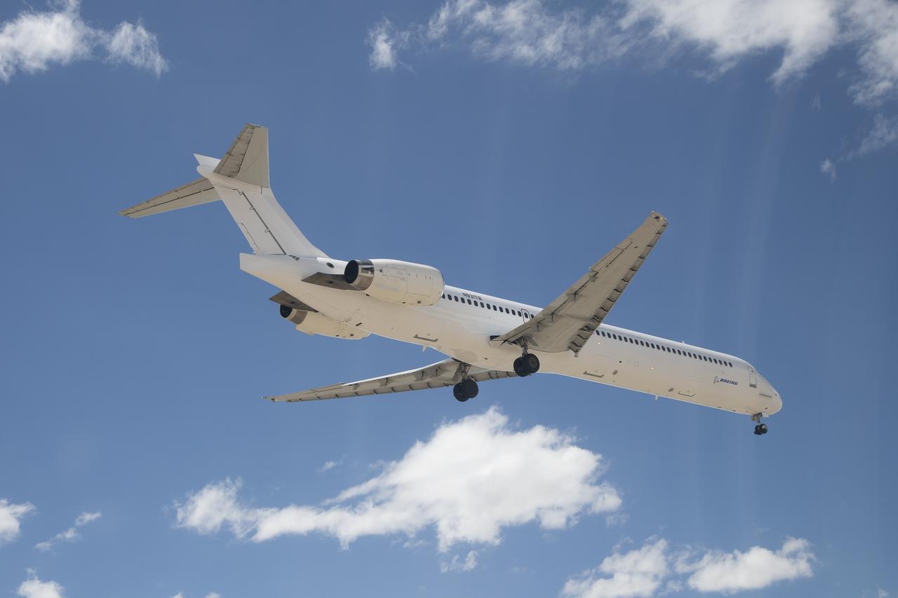
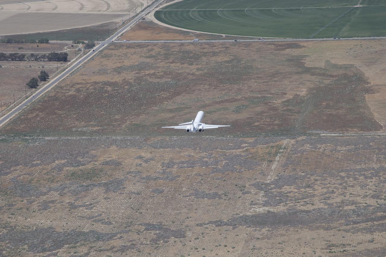
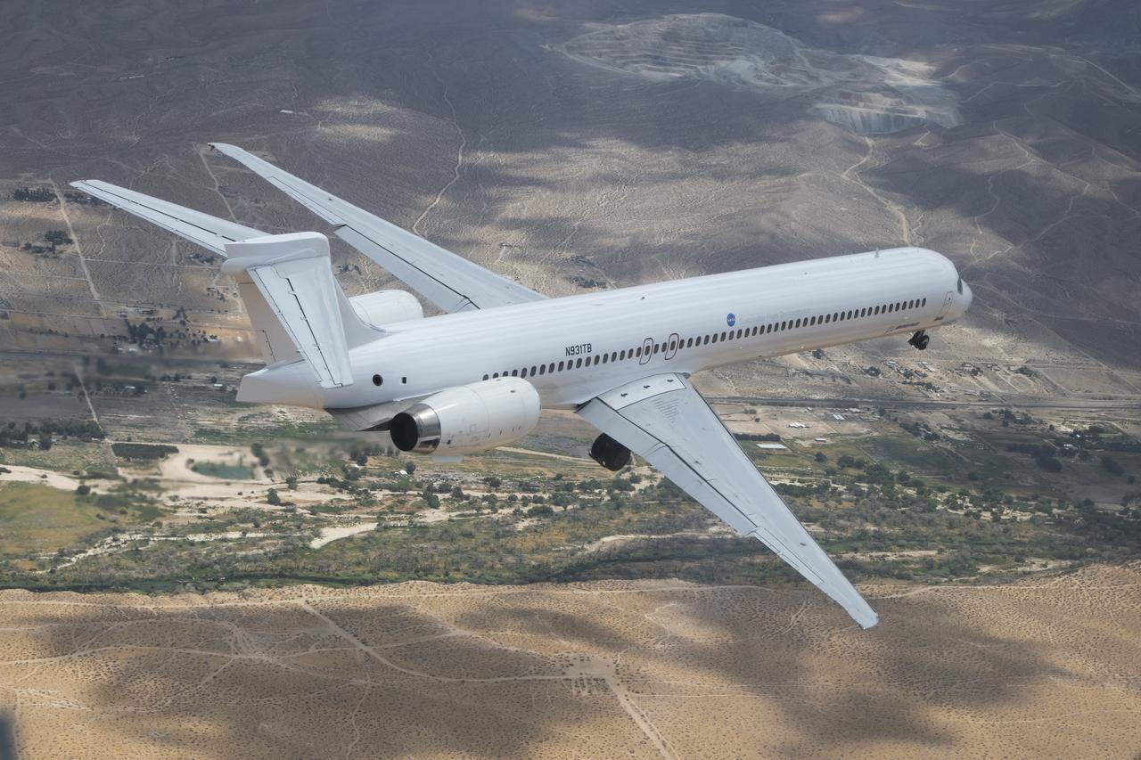
Boeing’s MD-90 aircraft flies from Victorville California to Palmdale, California on August 15, 2023. This aircraft will be NASA’s future Sustainable Flight Demonstrator. Modifications to the aircraft will include changes to the fuselage and most notably the use of a transonic truss-braced wing.
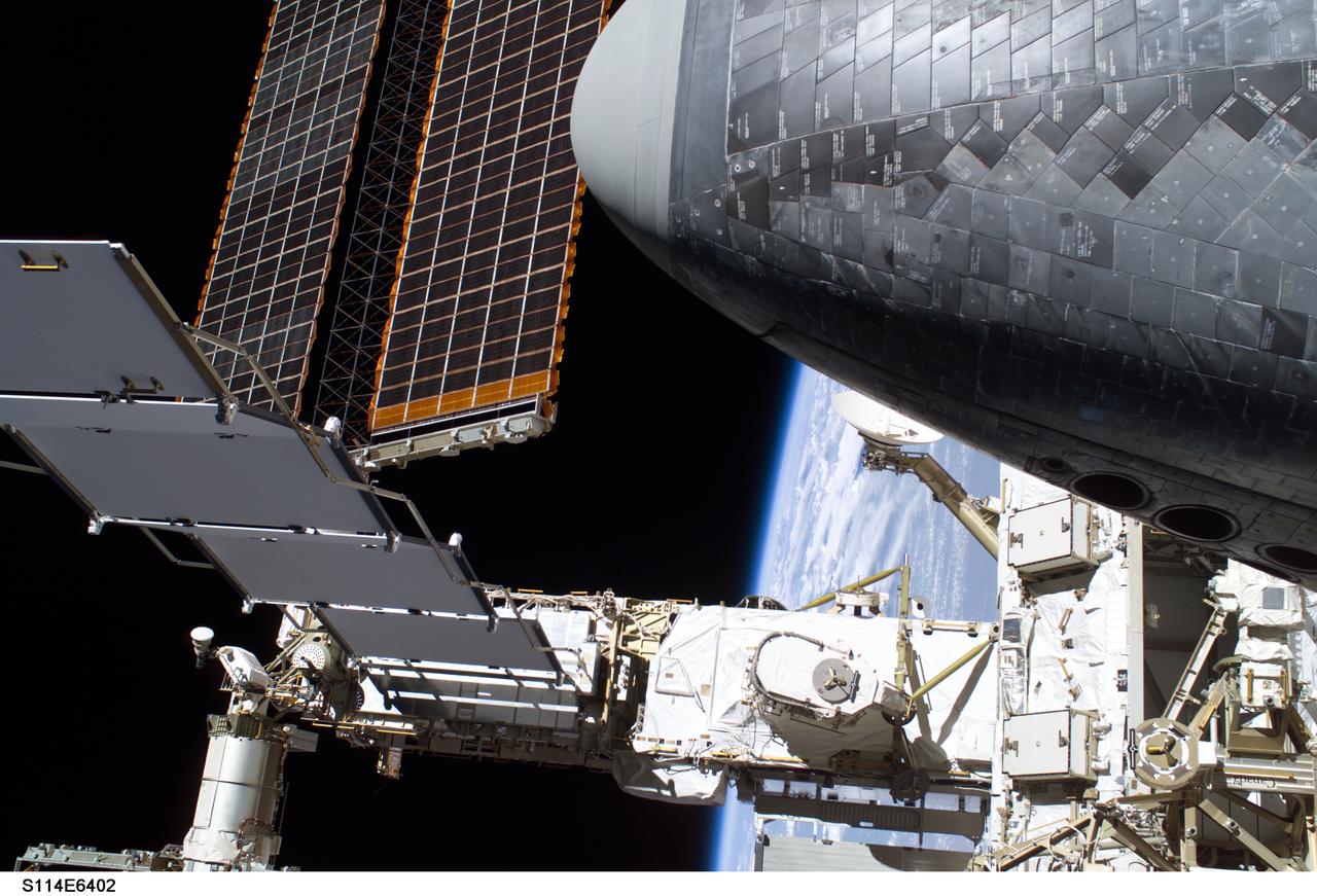
Photograph documenting the P6 Truss Solar Array Wing (SAW), Mast Canisters, Photovoltaic (PV) Radiator and Solar Array Blanket Boxes (SABB) as seen by the STS-114 crew during the third of three Extravehicular Activities (EVAs) of the mission. Part of the orbiter Discovery's nosecone is visible in the upper right of the frame.
Boeing’s MD-90 aircraft flies from Victorville California to Palmdale, California on August 15, 2023. This aircraft will be NASA’s future Sustainable Flight Demonstrator. Modifications to the aircraft will include changes to the fuselage and most notably the use of a transonic truss-braced wing.
Boeing’s MD-90 aircraft flies from Victorville California to Palmdale, California on August 15, 2023. This aircraft will be NASA’s future Sustainable Flight Demonstrator. Modifications to the aircraft will include changes to the fuselage and most notably the use of a transonic truss-braced wing.

JSC2006-E-43499 (October 2006) --- Computer-generated artist's rendering of the International Space Station after flight STS-116/12A.1. Space Shuttle Discovery crew delivers and installs the third port truss segment (P5). P6 port solar array wing and two radiators are retracted.
Boeing’s MD-90 aircraft flies from Victorville California to Palmdale, California on August 15, 2023. This aircraft will be NASA’s future Sustainable Flight Demonstrator. Modifications to the aircraft will include changes to the fuselage and most notably the use of a transonic truss-braced wing.
Boeing’s MD-90 aircraft flies from Victorville California to Palmdale, California on August 15, 2023. This aircraft will be NASA’s future Sustainable Flight Demonstrator. Modifications to the aircraft will include changes to the fuselage and most notably the use of a transonic truss-braced wing.
Boeing’s MD-90 aircraft flies from Victorville California to Palmdale, California on August 15, 2023. This aircraft will be NASA’s future Sustainable Flight Demonstrator. Modifications to the aircraft will include changes to the fuselage and most notably the use of a transonic truss-braced wing.
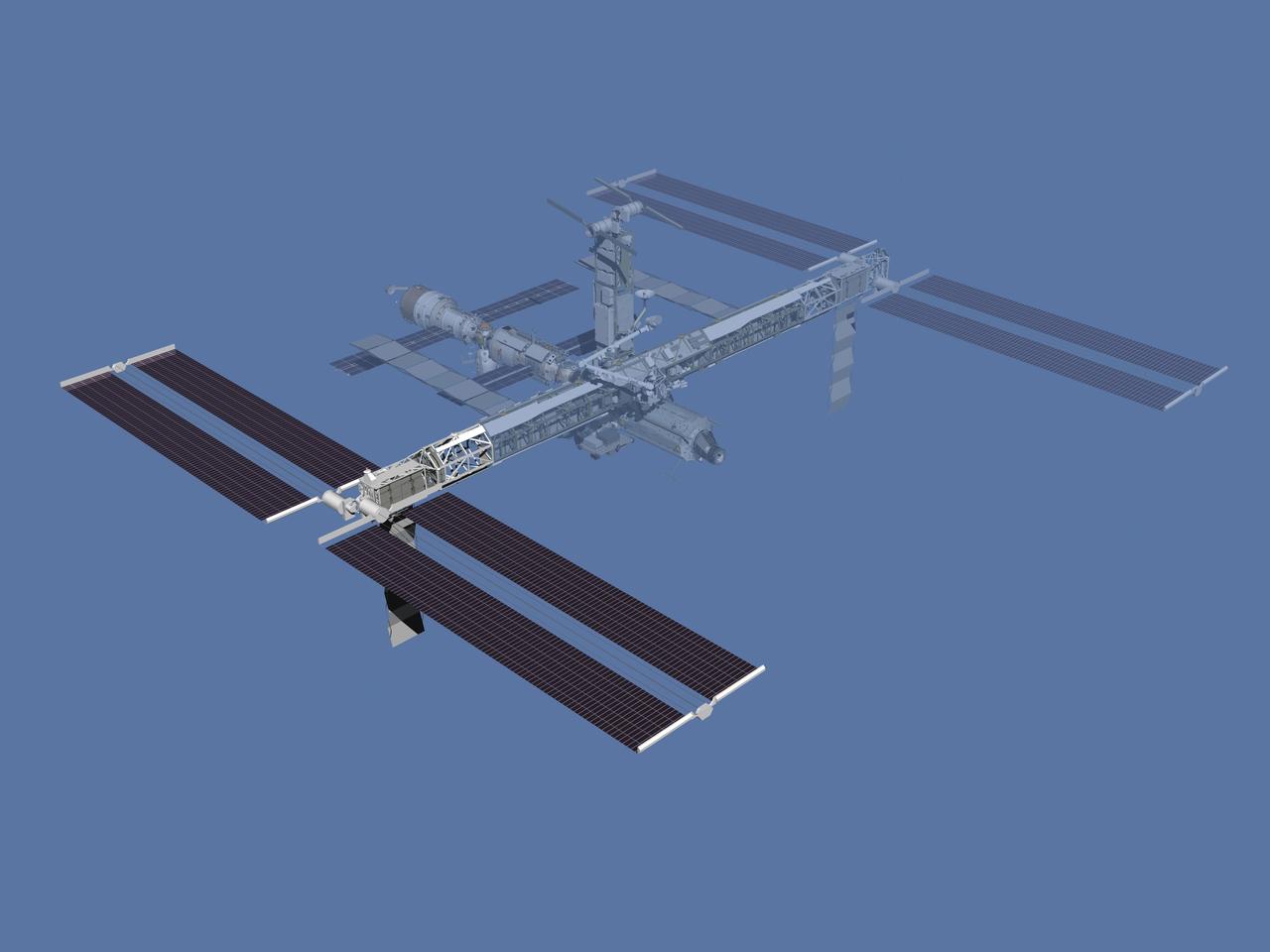
JSC2006-E-43500 (October 2006) --- Computer-generated artist's rendering of the International Space Station after flight STS-117/13A. Second starboard truss segment (S3/S4) is delivered and installed. The third set of solar arrays is deployed. P6 starboard solar array wing and one radiator are retracted.
Boeing’s MD-90 aircraft flies from Victorville California to Palmdale, California on August 15, 2023. This aircraft will be NASA’s future Sustainable Flight Demonstrator. Modifications to the aircraft will include changes to the fuselage and most notably the use of a transonic truss-braced wing.
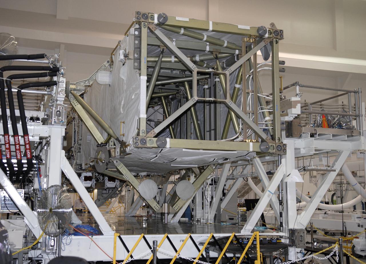
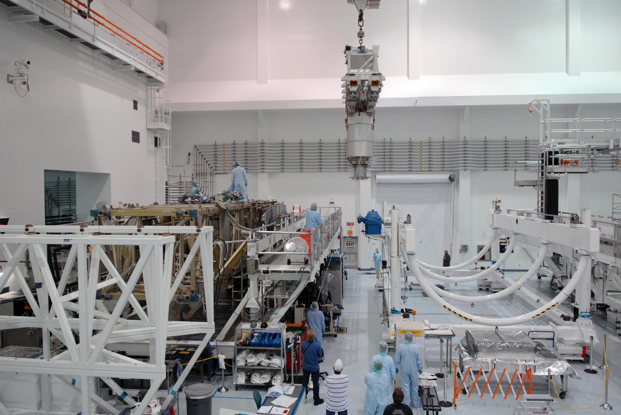
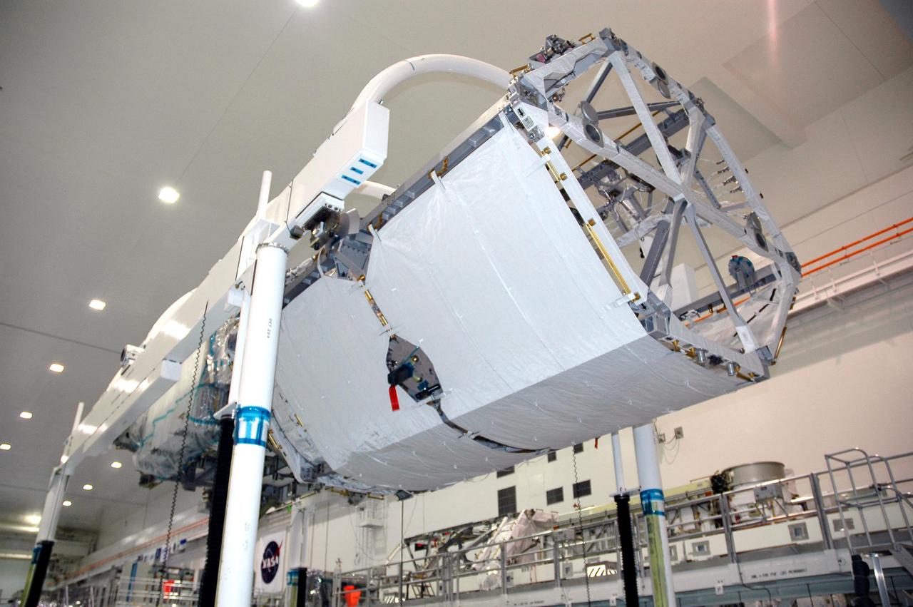
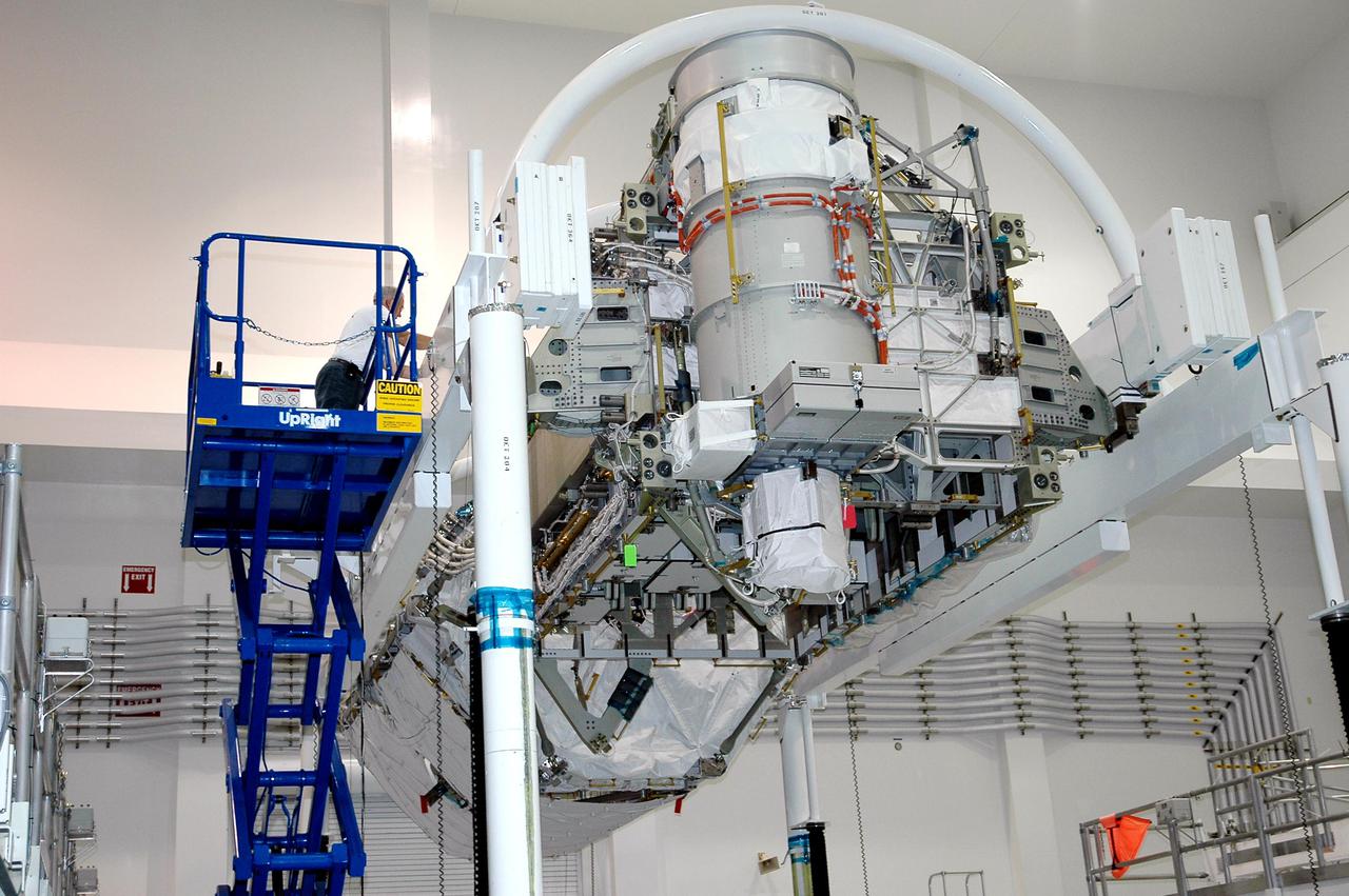
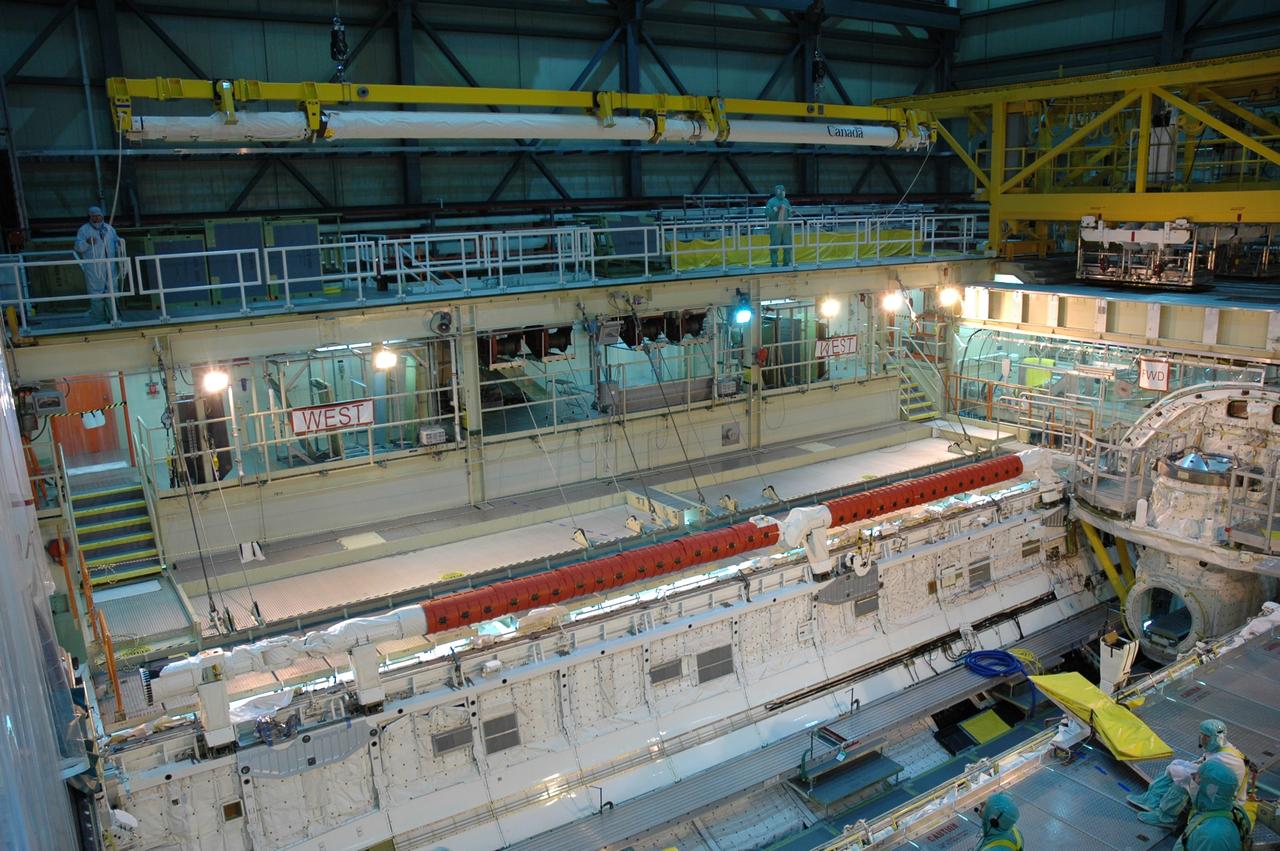
CAPE CANAVERAL, Fla. -- In the Space Station Processing Facility, the S6 truss segment is on display for the media at NASA's Kennedy Space Center in Florida. The S6 truss segment, with its set of large U.S. solar arrays, will be attached to the starboard, or right, side of the station during space shuttle Discovery's STS-119 mission. The S6 truss will complete the backbone of the station. The two solar wings will provide one-fourth of the total power needed to support a crew of six astronauts. The segment is expected to be loaded into the payload transportation canister Jan. 7, in preparation for its targeted journey to the launch pad Jan. 11. Photo credit: NASA/Kim Shiflett

CAPE CANAVERAL, Fla. -- In the Space Station Processing Facility at NASA's Kennedy Space Center in Florida, the S6 truss segment is on display for the media. The S6 truss segment, with its set of large U.S. solar arrays, will be attached to the starboard, or right, side of the station during space shuttle Discovery's STS-119 mission. The S6 truss will complete the backbone of the station. The two solar wings will provide one-fourth of the total power needed to support a crew of six astronauts. The segment is expected to be loaded into the payload transportation canister Jan. 7, in preparation for its targeted journey to the launch pad Jan. 11. Photo credit: NASA/Kim Shiflett
CAPE CANAVERAL, Fla. -- In the Space Station Processing Facility at NASA's Kennedy Space Center in Florida, the S6 truss segment is on display for the media. The S6 truss segment, with its set of large U.S. solar arrays, will be attached to the starboard, or right, side of the station during space shuttle Discovery's STS-119 mission. The S6 truss will complete the backbone of the station. The two solar wings will provide one-fourth of the total power needed to support a crew of six astronauts. The segment is expected to be loaded into the payload transportation canister Jan. 7, in preparation for its targeted journey to the launch pad Jan. 11. Photo credit: NASA/Kim Shiflett