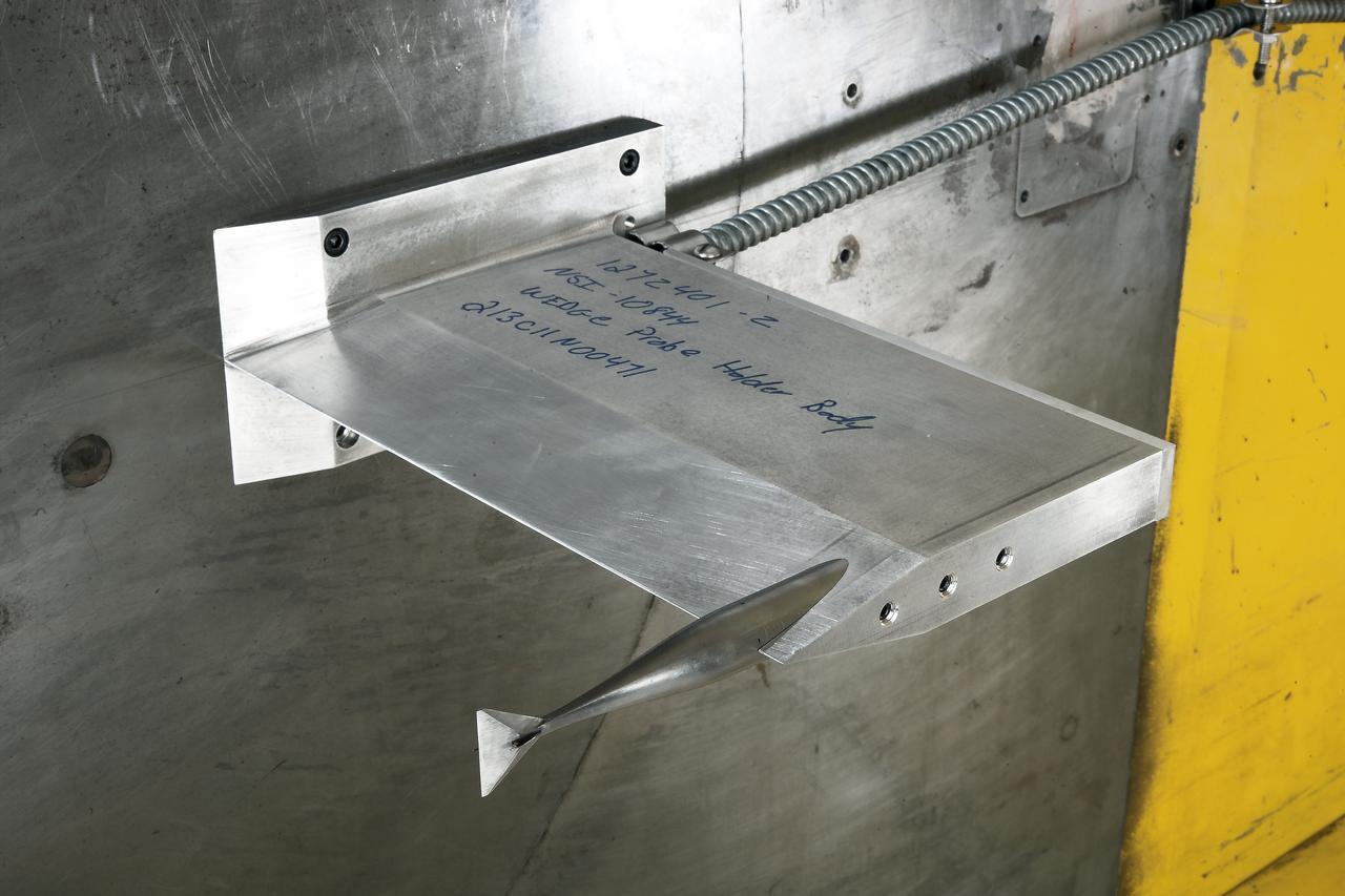
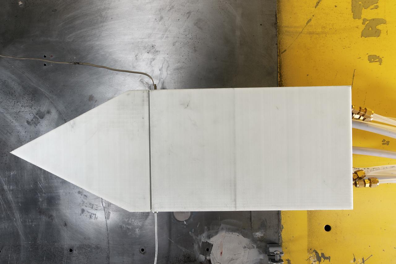
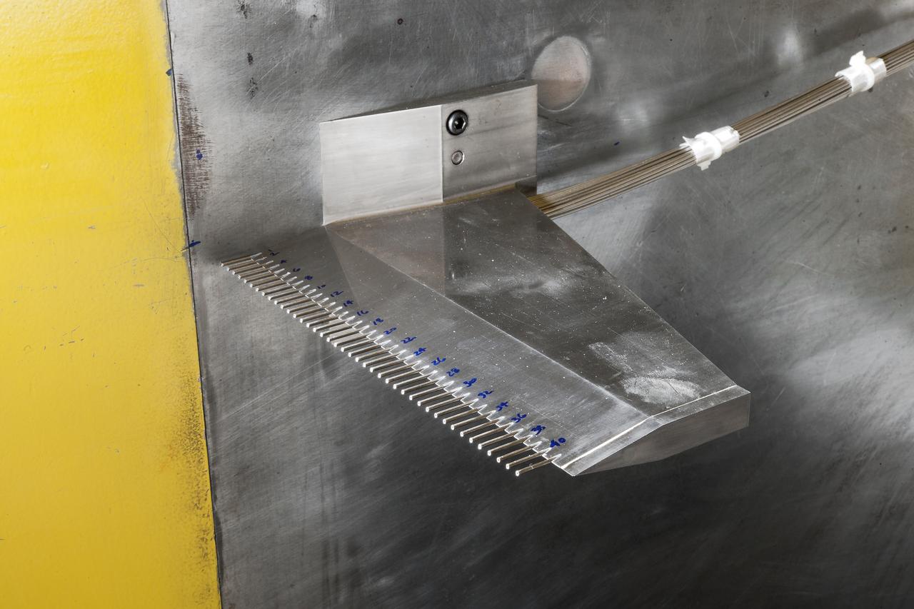
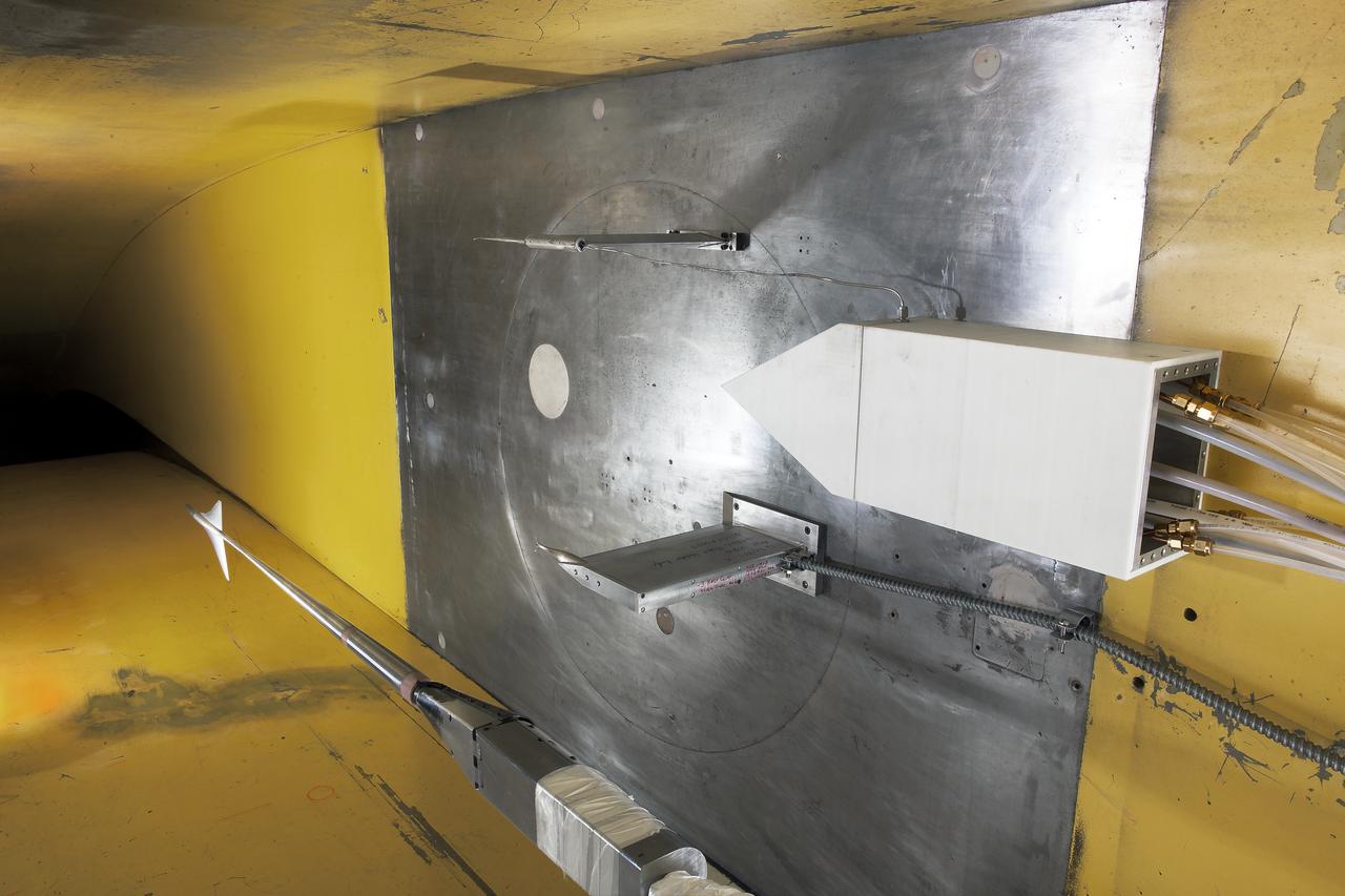
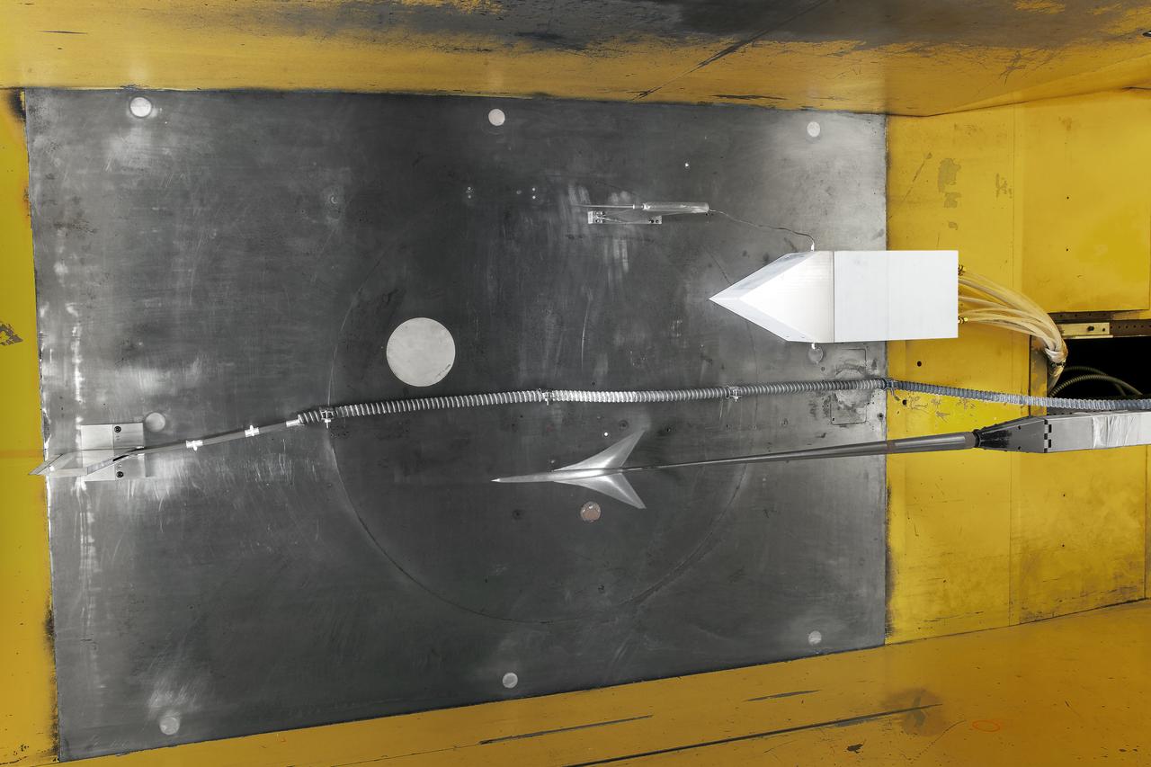
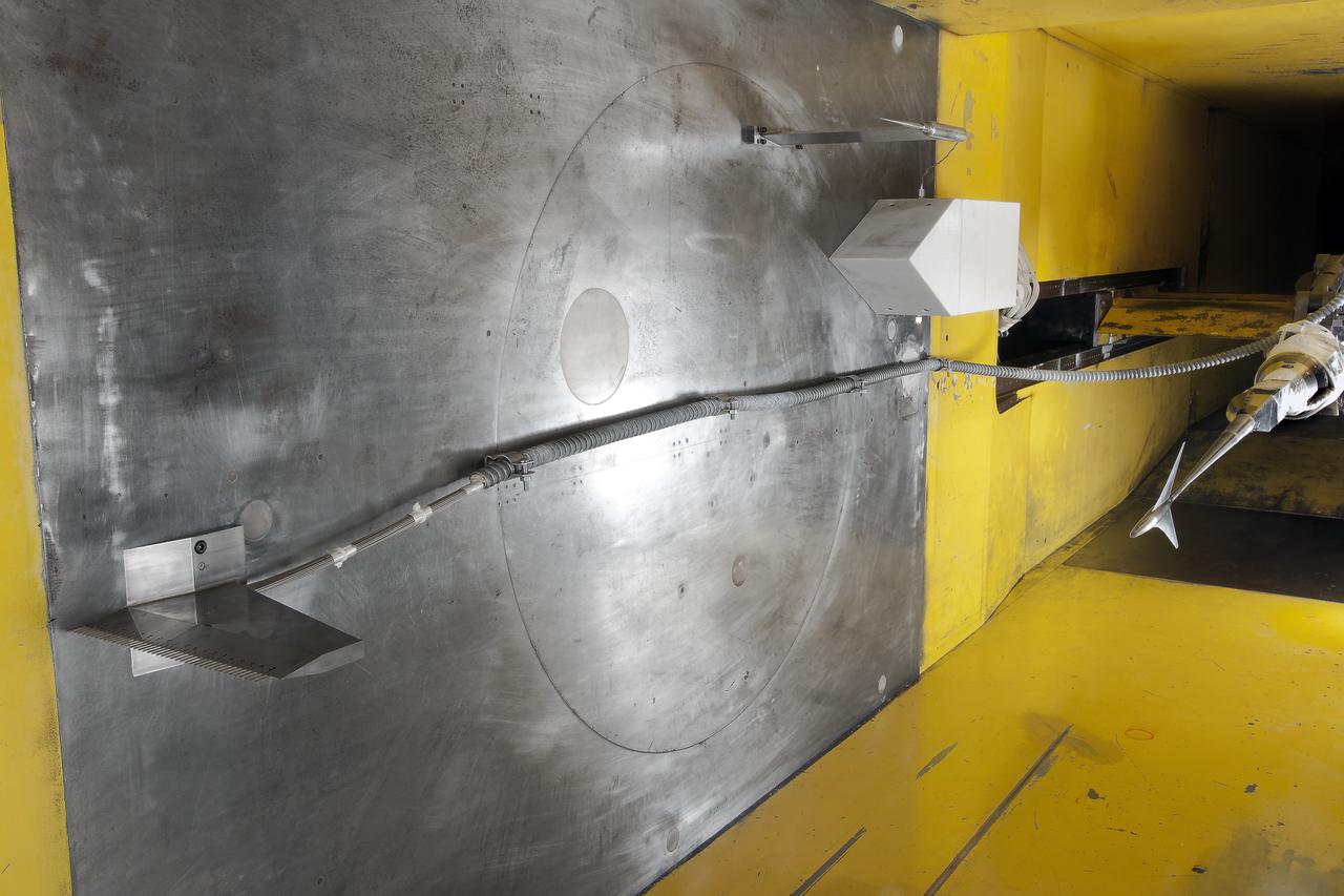
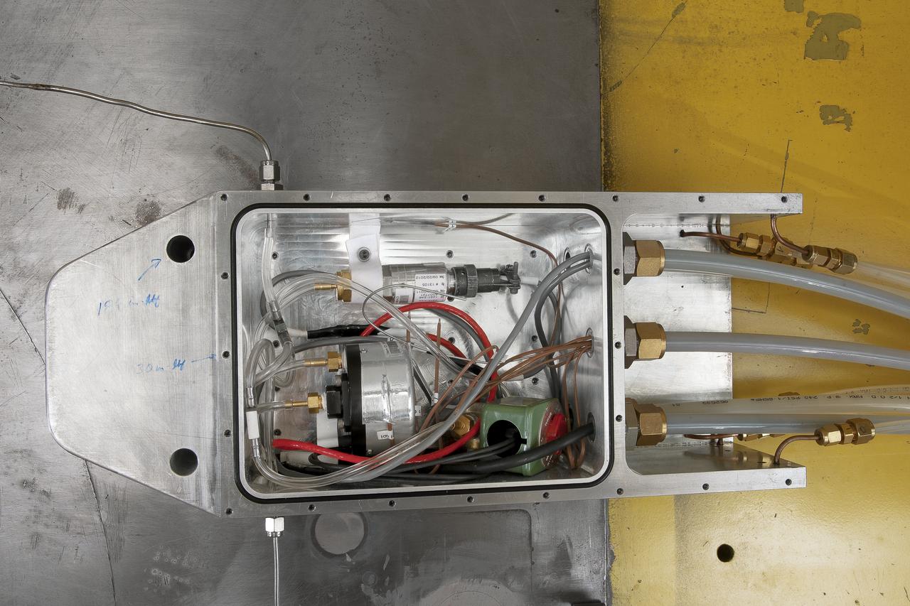
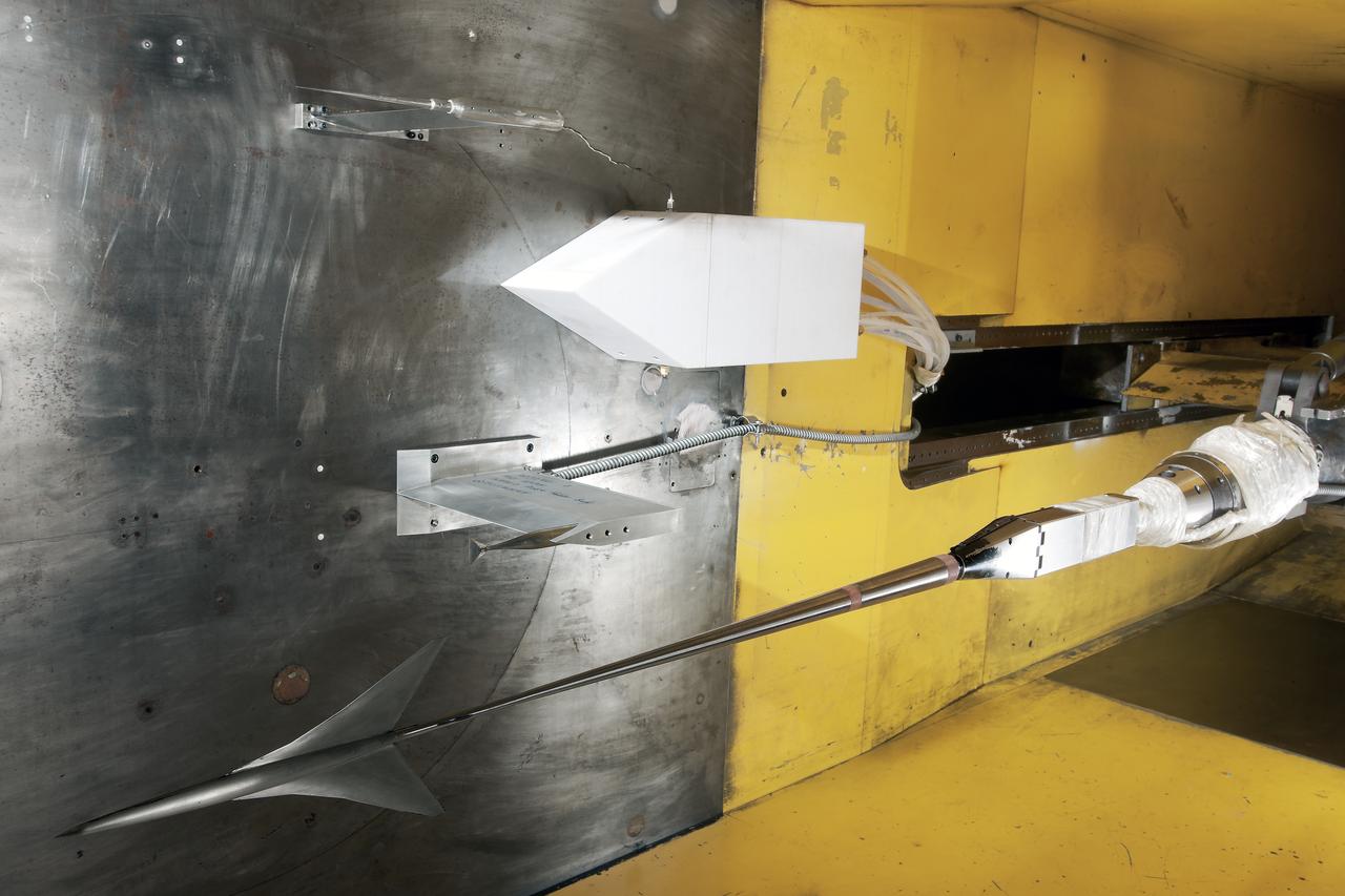
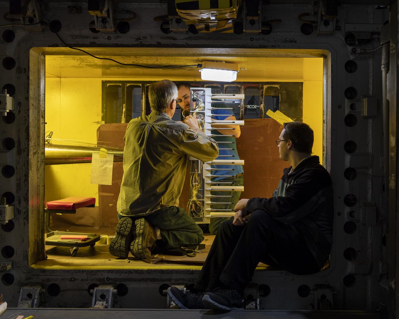
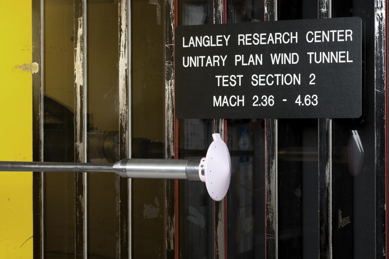
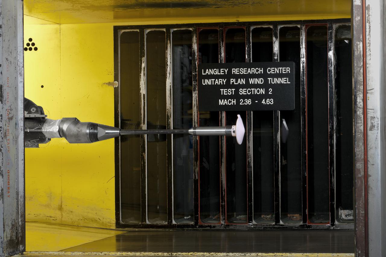
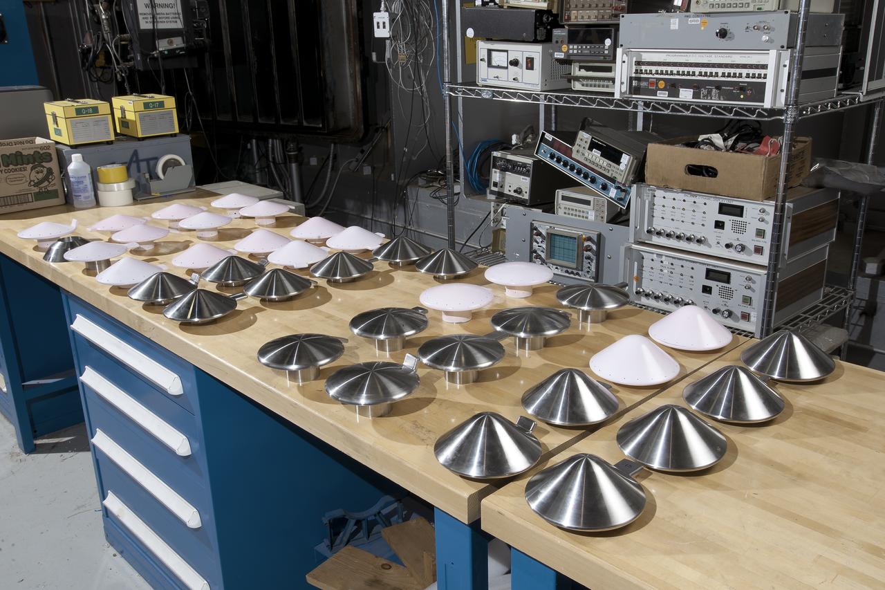
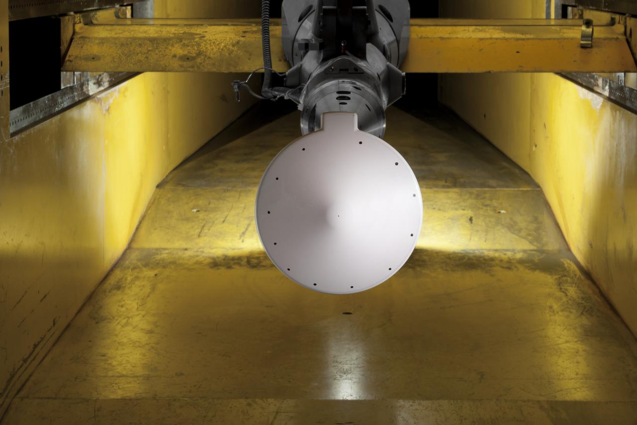
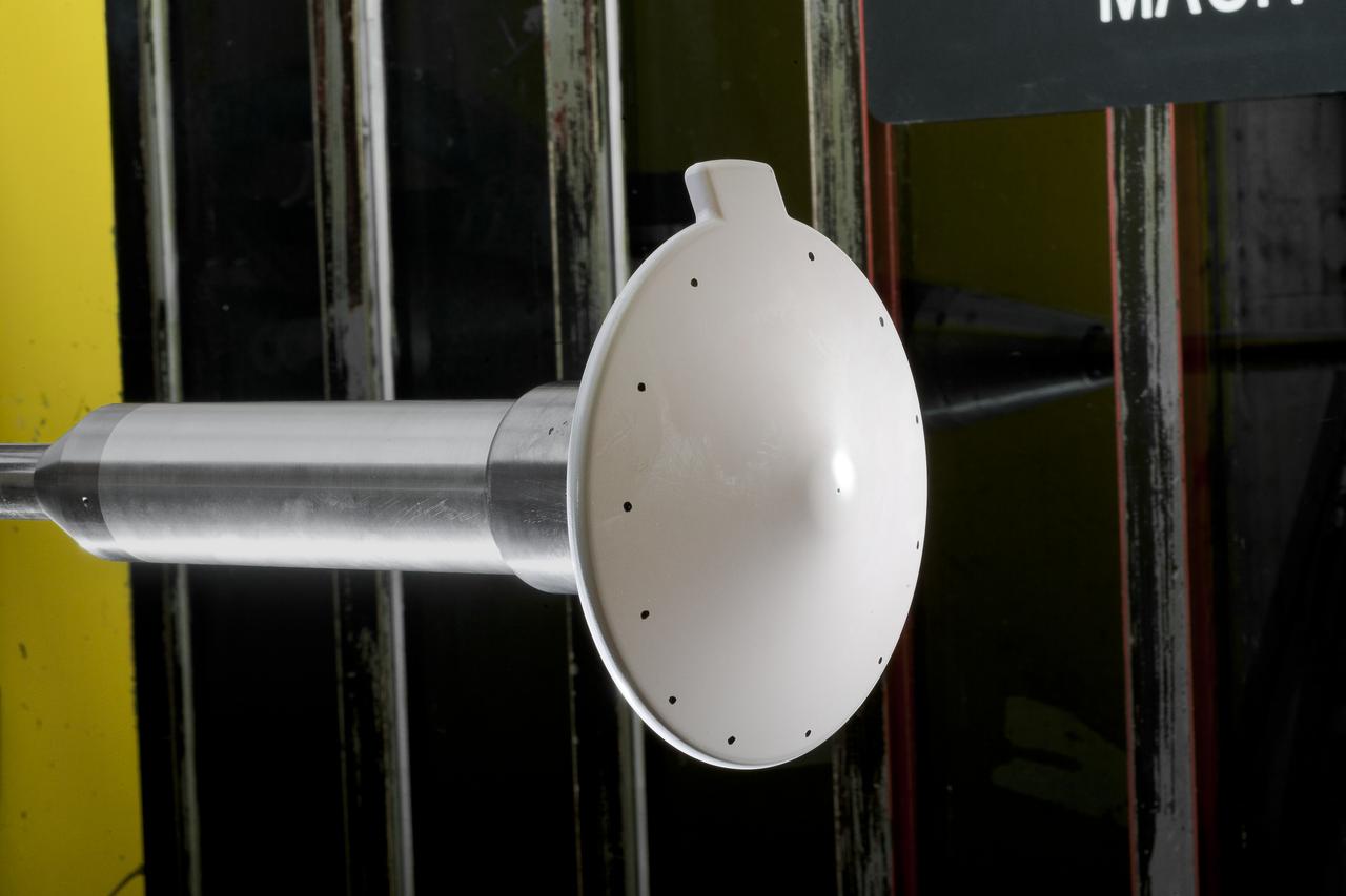
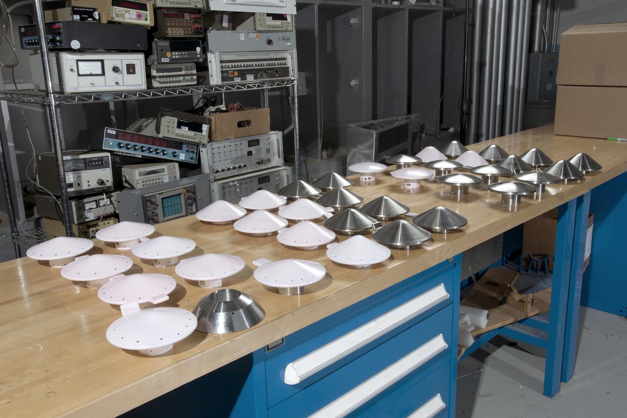
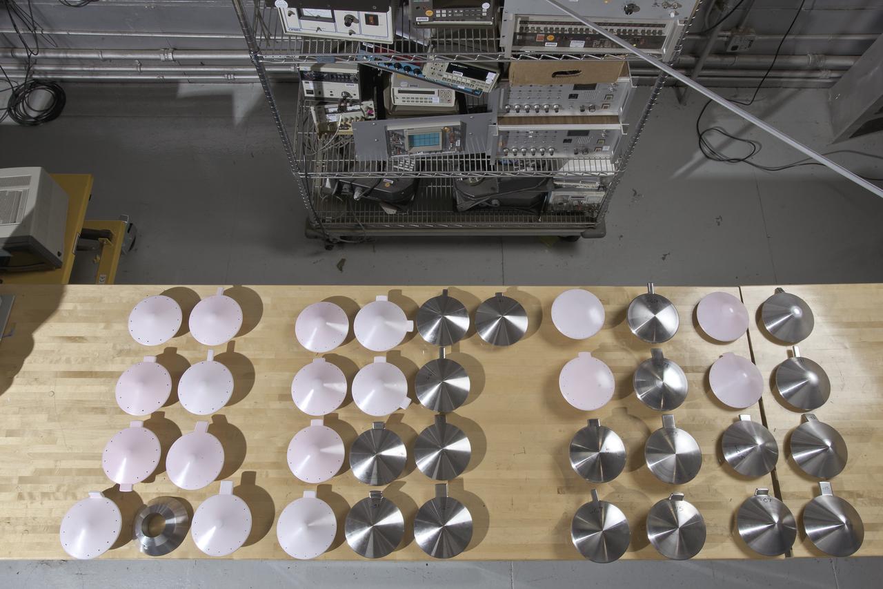
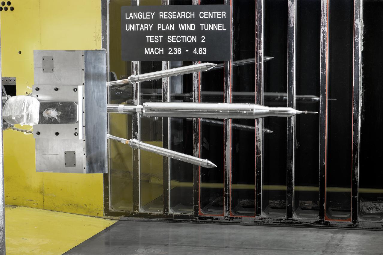
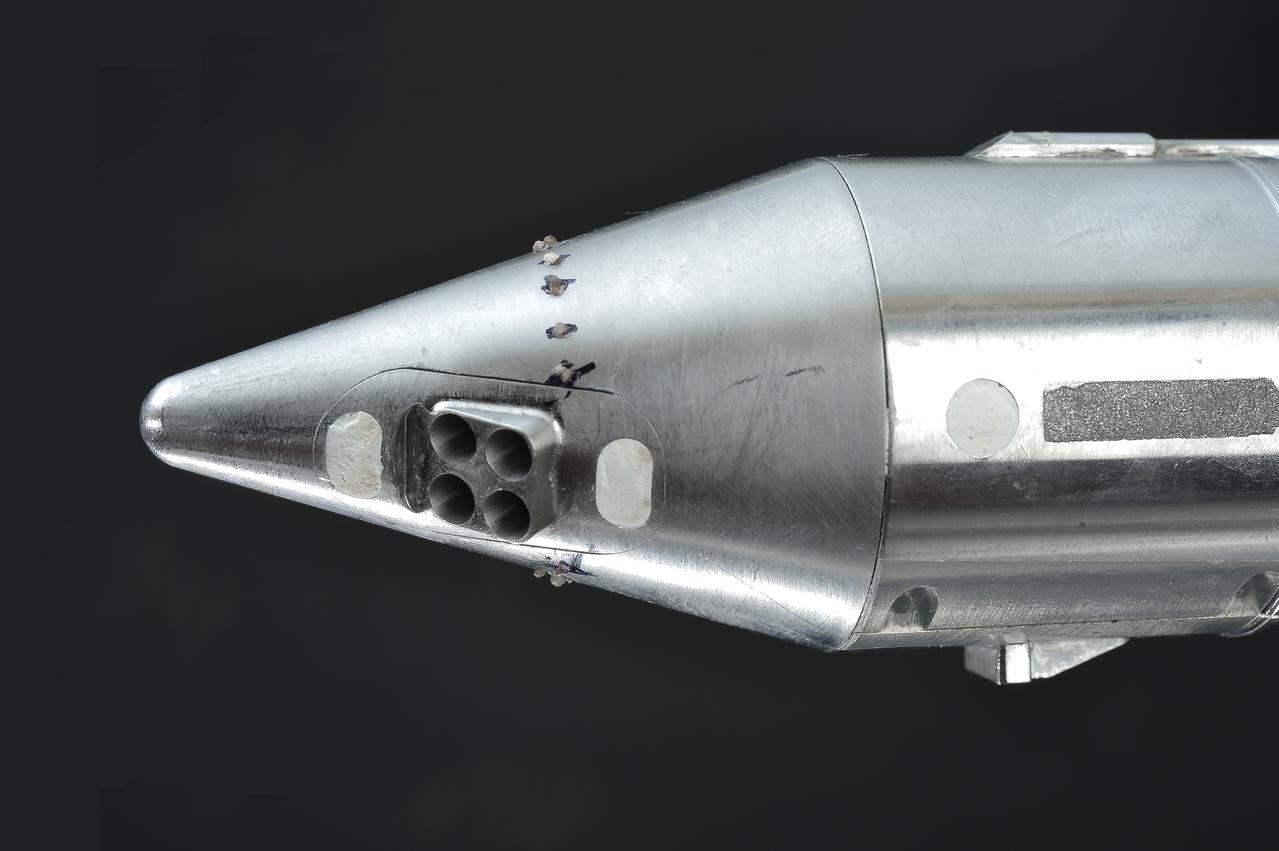
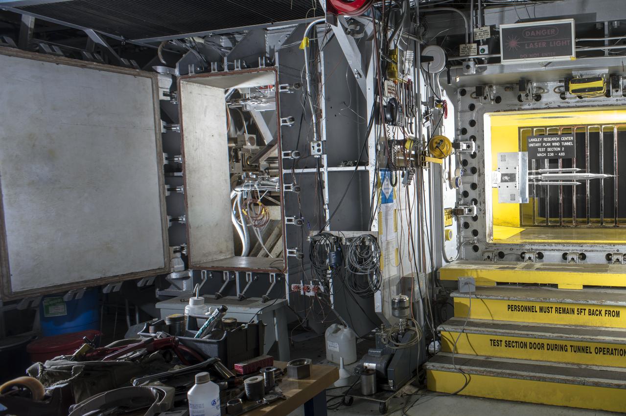
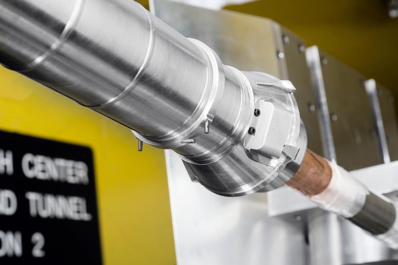
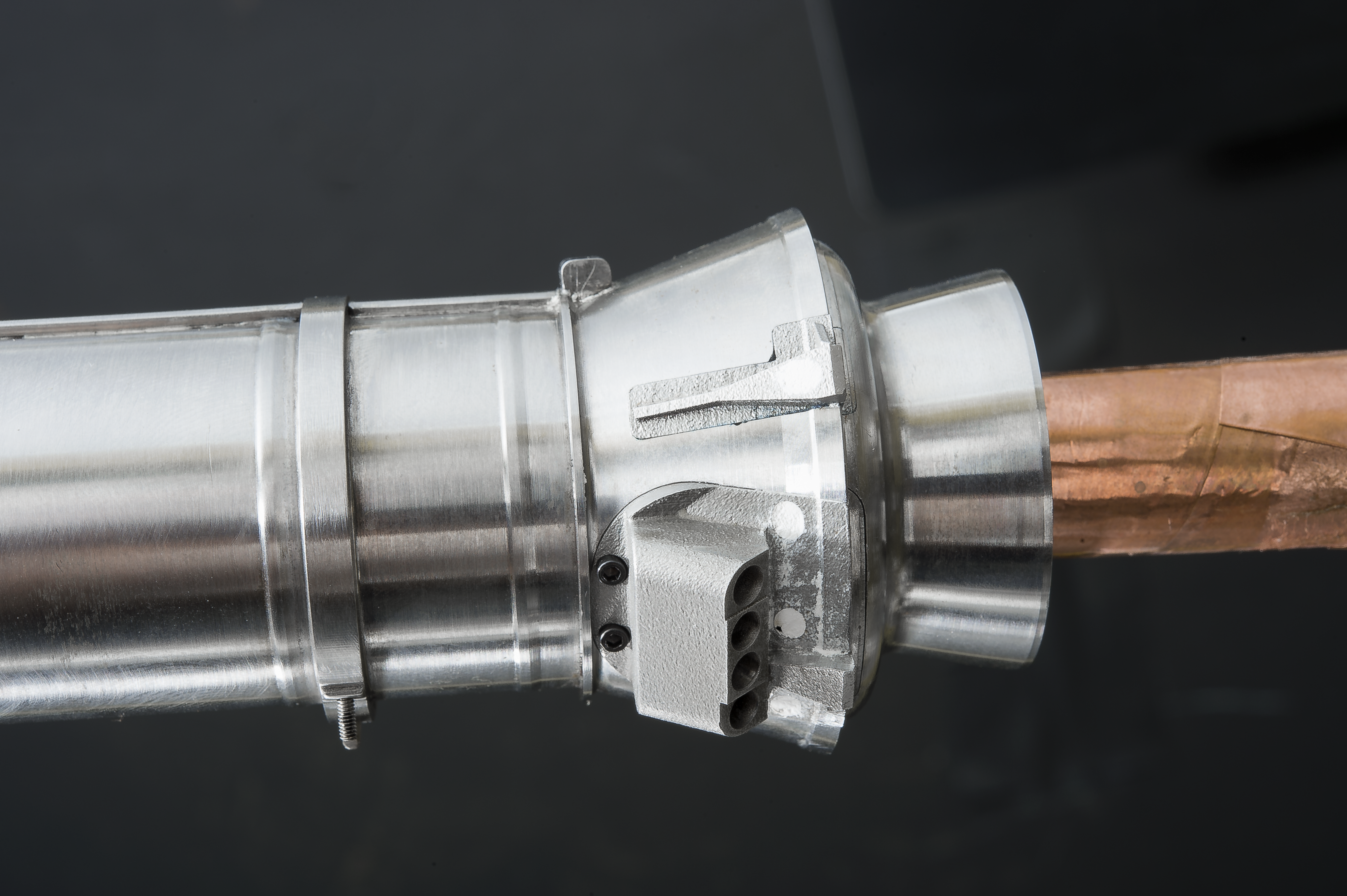
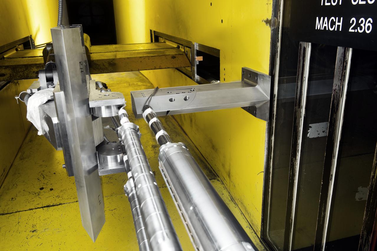
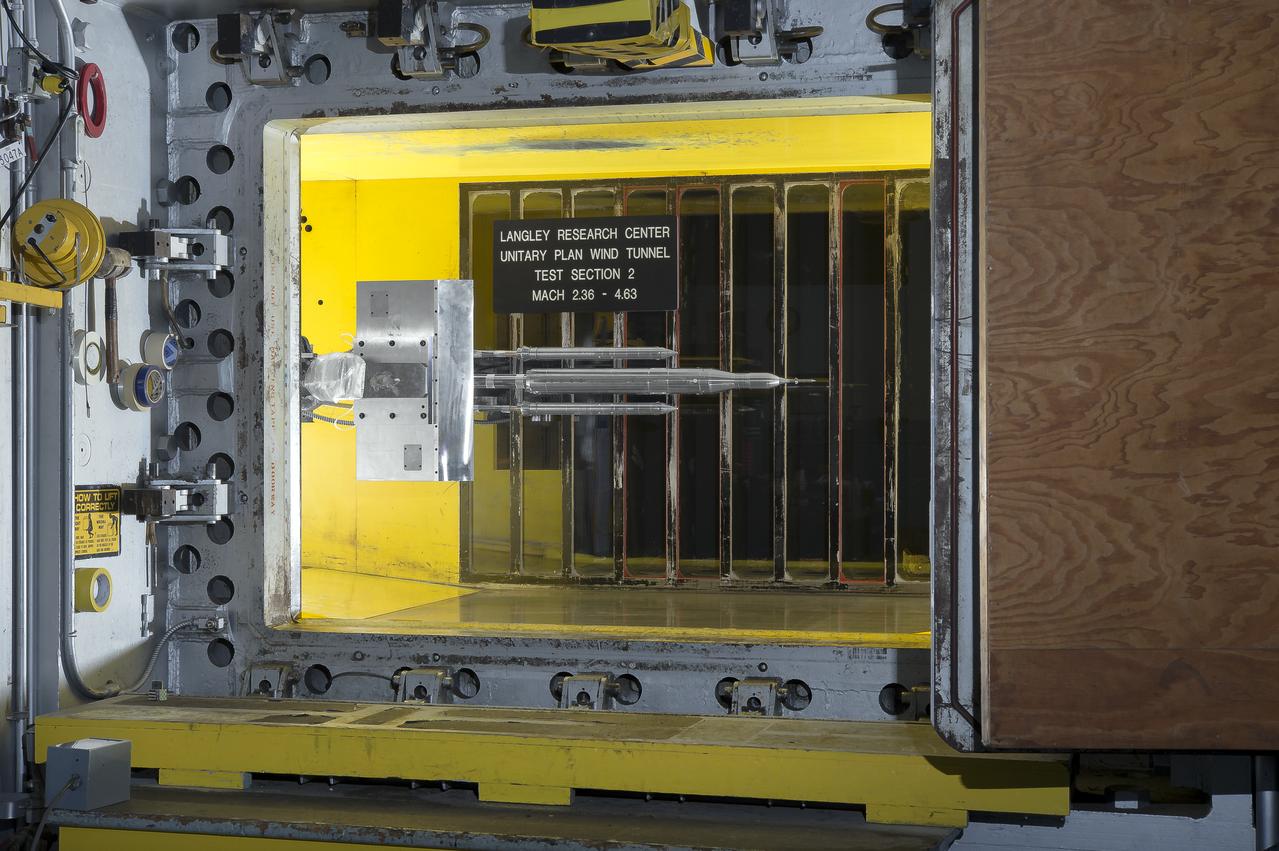
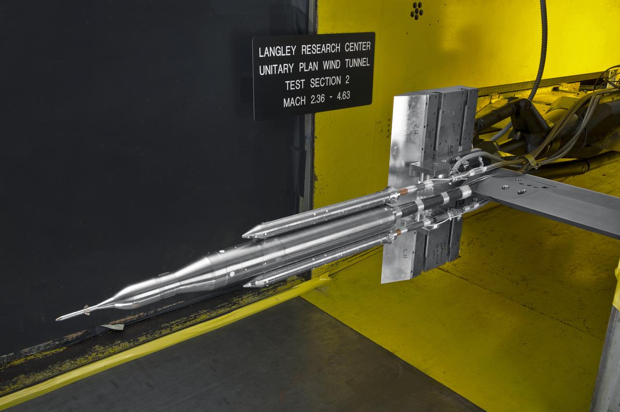
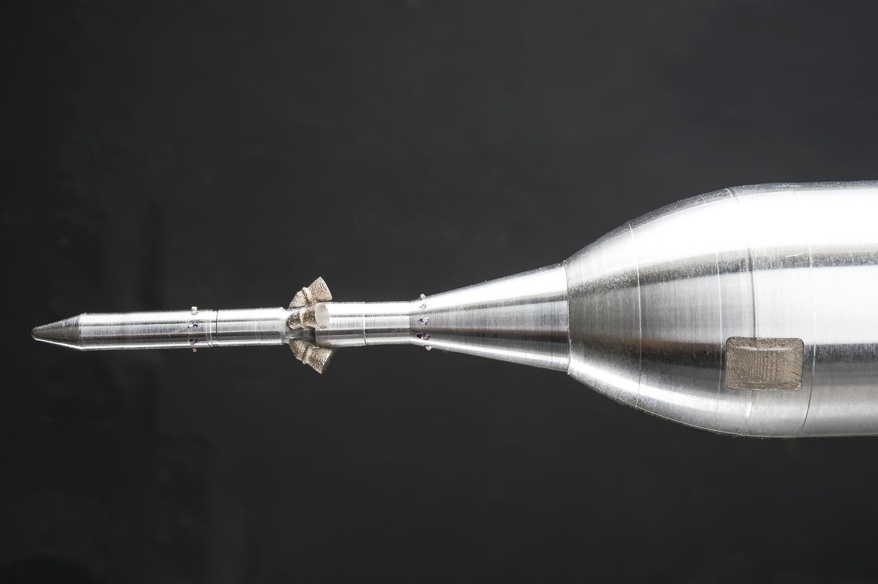
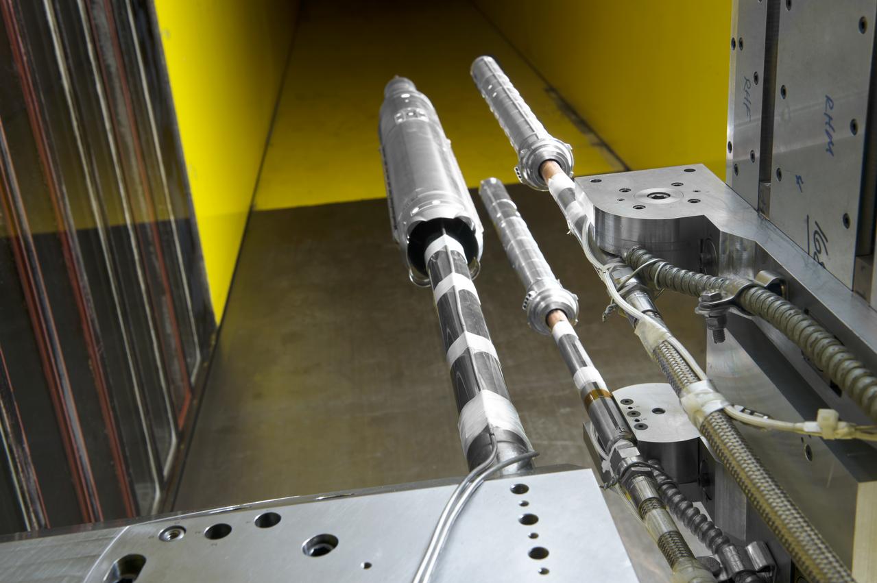
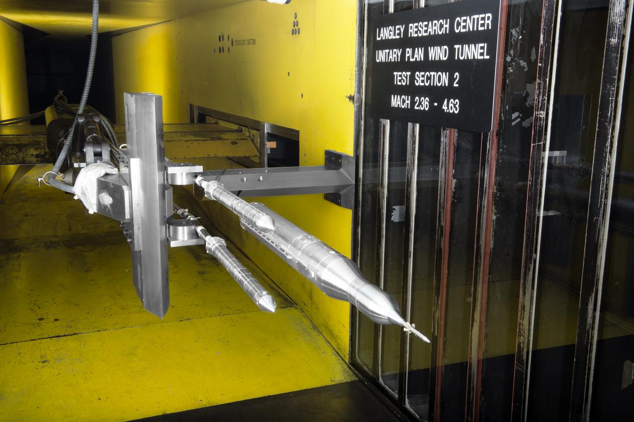
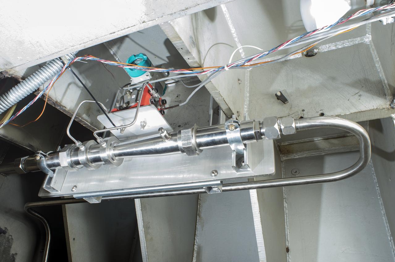
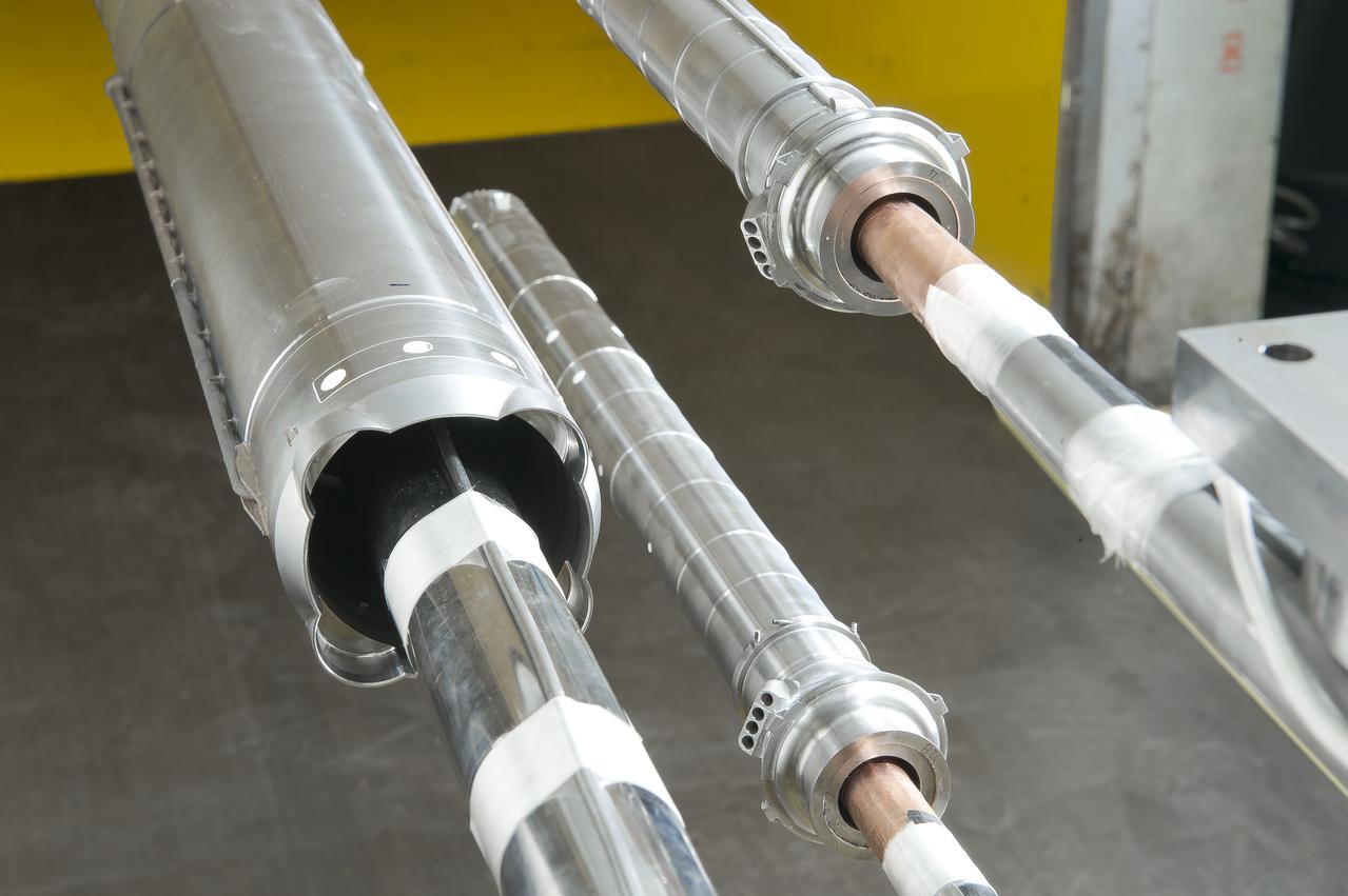
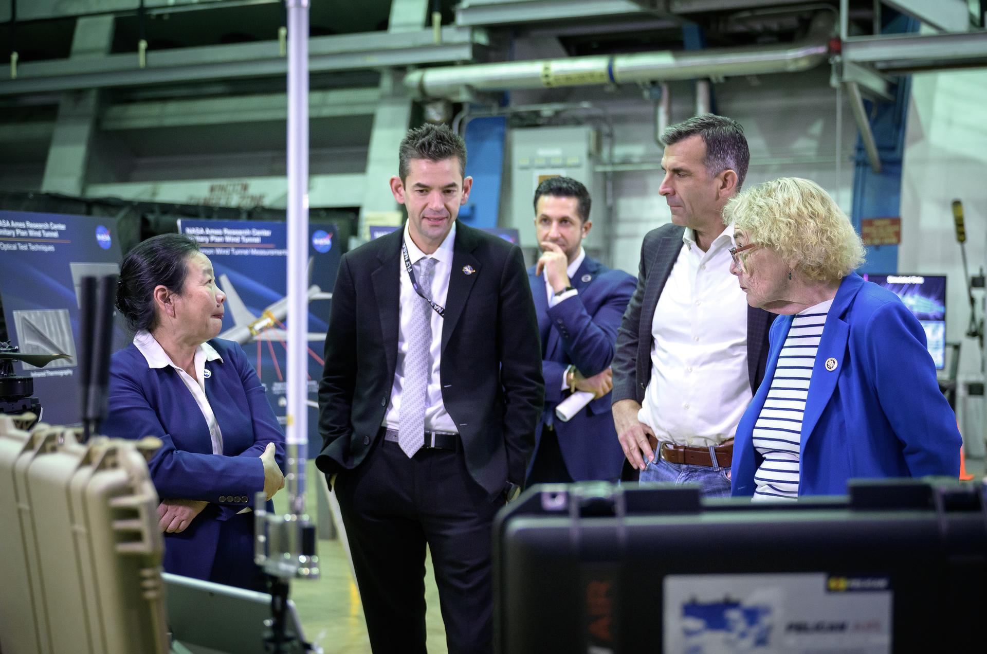
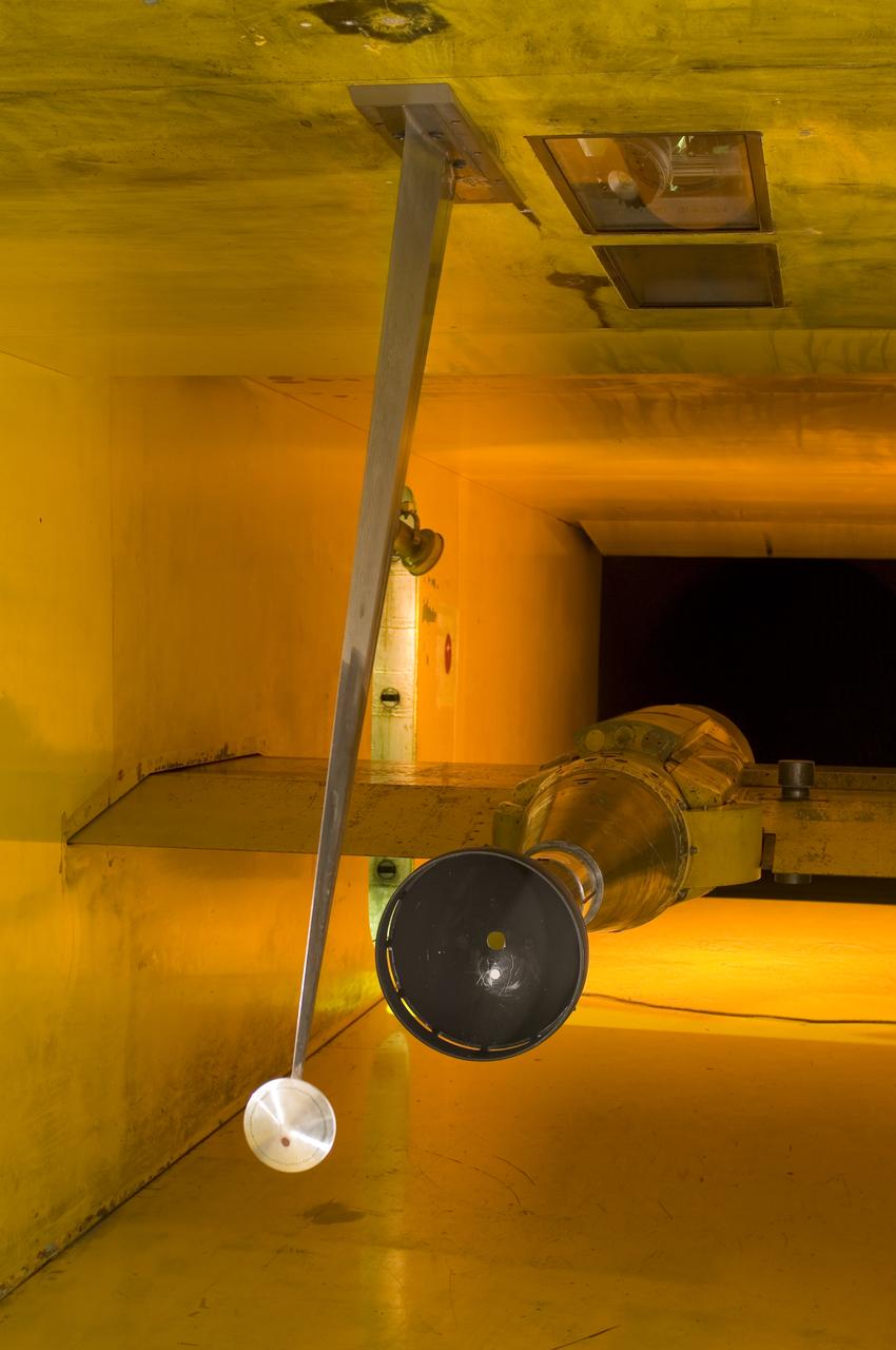
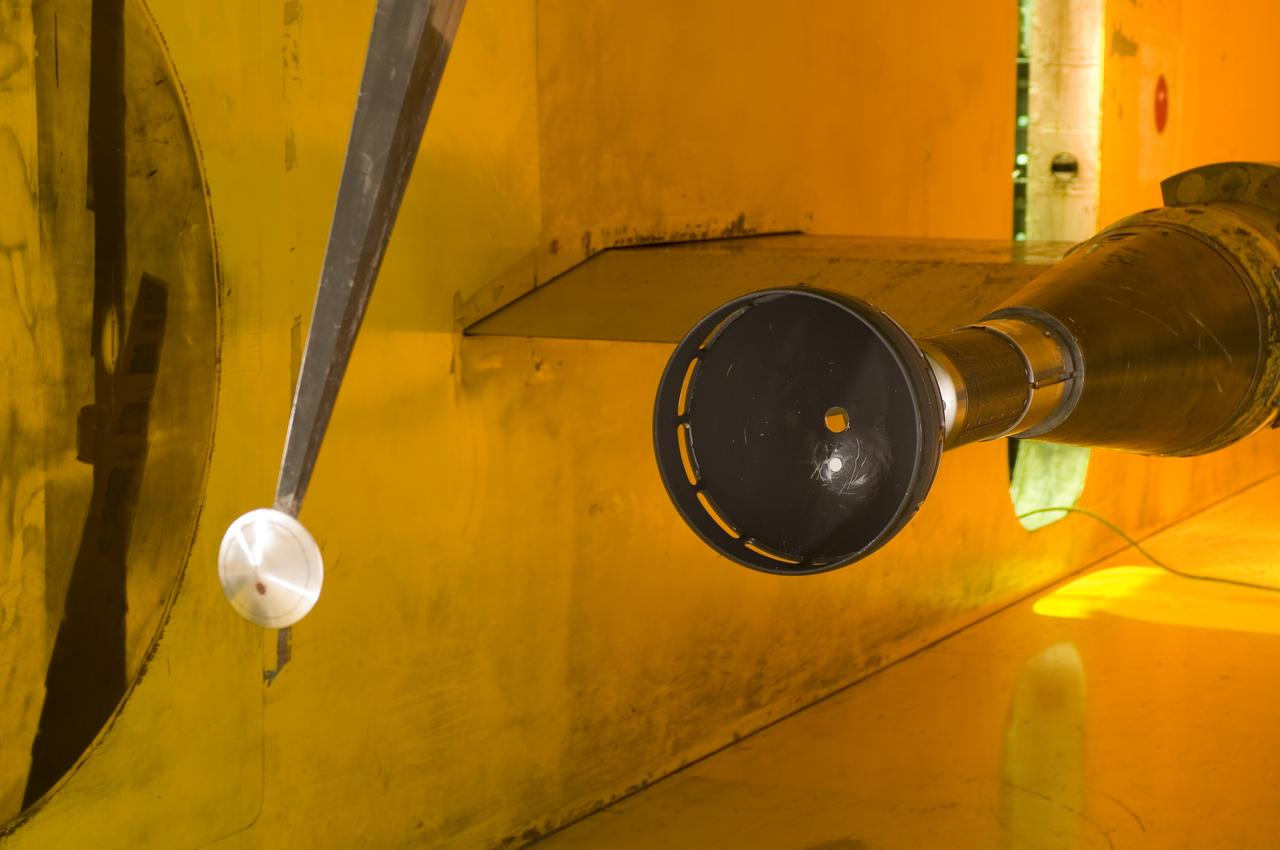
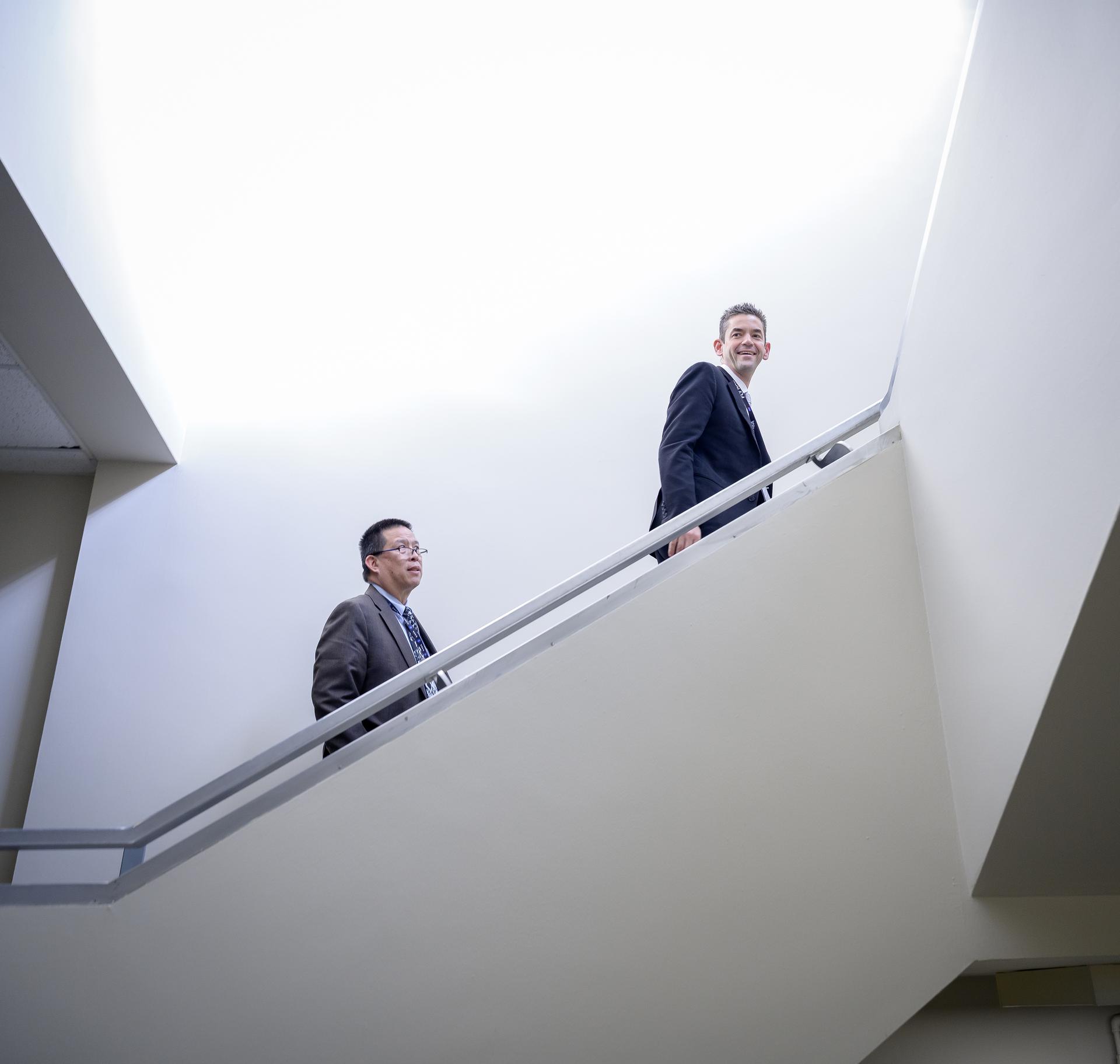
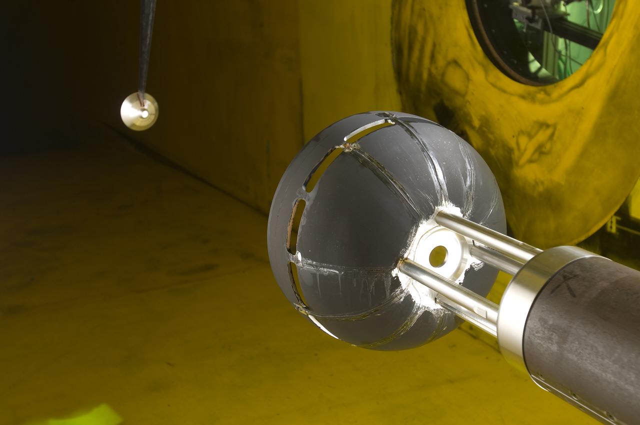
Two images left out of the original order in 2011 L numbers 3800-3810 2011. UPWT Test 1998 Continuous Data Sonic Boom Test. Sonic Boom Hardware Mounted in the Langley Unitary Plan wind Tunnel(UPWT). Conical survey probes, wedge probe, and wind tunnel wall boundary layer rake. Rectangular box with wedge front end is a transducer box to that held pressure transducer for the conical probes.
UPWT Test 1998 Continuous Data Sonic Boom Test.
UPWT Test 1998 Continuous Data Sonic Boom Test. Sonic Boom Hardward Mounted in the Langley Unitary Plan wind Tunnel(UPWT). Conical survey probes, wedge probe, and wind tunnel wall boundary layer rake. Rectangular box with wedge front end is a transducer box to that held pressure transducer for the conical probes.
(UPWT)Unitary Plan wind Tunnel Test 1998 Continuous Data Sonic B
LaRC OCIO's Media Solutions Branch Photographer Harlen Capen photographed the installation of a new flow survey rake for the supersonic Unitary Plan Wind Tunnel (UPWT). The hardware – shown installed in the 4-foot, high-Mach-number Test Section 2 with a coating of Pressure Sensitive Paint – consists of a purpose-built sting, rake body, and two different types of pressure measurement probes. The survey rake will be used to characterize the flow in the test section in support of the "CFD Central Flight Dynamics as a Surrogate for High Speed Supersonic Tests"  People in the photo L to R  are, Ricky L. Hall, Jacobs Technology, Inc.,Supersonic/Hypersonic Testing Branch - Group A, Alexander (Alex) Moore Jacobs Technology, Inc, Supersonic/Hypersonic Testing Branch and Mathew A. (Alec) Reed, Jacobs Technology, In.   NASA photographer Harlen Capen won First Place in the NASA's 2019 Still Photographer of the Year competition in the "People" category with this image.
UPWT
NASA Administrator Jared Isaacman listens to a presentation by wind tunnel staff in the Unitary Plan Wind Tunnel (UPWT) facility in N227.
NASA Administrator Jared Isaacman’s Visit to Ames
Wind tunnel staff Mike Treece and Wind Tunnel Division Chief Maureen Delgado greet NASA Administrator Jared Isaacman in the lobby of the Unitary Plan Wind Tunnel (UPWT) facility in N227.
NASA Administrator Jared Isaacman’s Visit to Ames
NASA Administrator Jared Isaacman meets wind tunnel staff during a tour of the Unitary Plan Wind Tunnel (UPWT) facility in N227.
NASA Administrator Jared Isaacman’s Visit to Ames
NASA Administrator Jared Isaacman meets Congresswoman Zoe Lofgren during a tour of the Unitary Plan Wind Tunnel (UPWT) facility in N227.
NASA Administrator Jared Isaacman’s Visit to Ames
Test 1875 in Unitary Plan Wind Tunnel (UPWT) HIADS TTPM: Trim Tab study on various cone angled heat shields (TTPM) Technology Technical Performance Metric (HIADS) Hypersonic inflatable aerodynamic decelerators
Test 1875 in Unitary Plan Wind Tunnel (UPWT) HIADS TTPM
Test 1875 in Unitary Plan Wind Tunnel (UPWT) HIADS TTPM: Trim Tab study on various cone angled heat shields (TTPM) Technology Technical Performance Metric (HIADS) Hypersonic inflatable aerodynamic decelerators
Test 1875 in Unitary Plan Wind Tunnel (UPWT) HIADS TTPM
Test 1875 in Unitary Plan Wind Tunnel (UPWT) HIADS TTPM: Trim Tab study on various cone angled heat shields (TTPM) Technology Technical Performance Metric (HIADS) Hypersonic inflatable aerodynamic decelerators
Test 1875 in Unitary Plan Wind Tunnel (UPWT) HIADS TTPM
Test 1875 in Unitary Plan Wind Tunnel (UPWT) HIADS TTPM: Trim Tab study on various cone angled heat shields (TTPM) Technology Technical Performance Metric (HIADS) Hypersonic inflatable aerodynamic decelerators
Test 1875 in Unitary Plan Wind Tunnel (UPWT) HIADS TTPM
Test 1875 in Unitary Plan Wind Tunnel (UPWT) HIADS TTPM: Trim Tab study on various cone angled heat shields (TTPM) Technology Technical Performance Metric (HIADS) Hypersonic inflatable aerodynamic decelerators
Test 1875 in Unitary Plan Wind Tunnel (UPWT) HIADS TTPM
Test 1875 in Unitary Plan Wind Tunnel (UPWT) HIADS TTPM: Trim Tab study on various cone angled heat shields (TTPM) Technology Technical Performance Metric (HIADS) Hypersonic inflatable aerodynamic decelerators
Test 1875 in Unitary Plan Wind Tunnel (UPWT) HIADS TTPM
Test 1875 in Unitary Plan Wind Tunnel (UPWT) HIADS TTPM: Trim Tab study on various cone angled heat shields (TTPM) Technology Technical Performance Metric (HIADS) Hypersonic inflatable aerodynamic decelerators
Test 1875 in Unitary Plan Wind Tunnel (UPWT) HIADS TTPM
Stage Separation Test of the Space Launch System(SLS) in the Langley Unitary Plan Wind Tunnel (UPWT). The model used High Pressure air blown through the solid rocket boosters. (SRB) to simulate the booster separation motors (BSM) firing.
The Unitary Plan Wind Tunnel(UPWT) Test 1891 Space Launch System
Director of Aeronautics Huy Tran, left, NASA Administrator Jared Isaacman, Associate Center Director Amir Deylami, back, Congressman Sam Liccardo, and Congresswoman Zoe Lofgren, right, tour the Unitary Plan Wind Tunnel (UPWT) facility in N227.
NASA Administrator Jared Isaacman’s Visit to Ames
MSL III  (Mars Science Laboratory) Test in UPWT 9x7ft with tunnel Test-97-159 These tests were for parachute entry deployment CFD validation.
ARC-2007-ACD07-0062-007
MSL III  (Mars Science Laboratory) Test in UPWT 9x7ft with tunnel Test-97-159 These tests were for parachute entry deployment CFD validation.
ARC-2007-ACD07-0062-005
NASA Administrator Jared Isaacman, right, and Center Director Eugene Tu tour the Unitary Plan Wind Tunnel (UPWT) facility in N227.
NASA Administrator Jared Isaacman’s Visit to Ames
MSL III  (Mars Science Laboratory) Test in UPWT 9x7ft with tunnel Test-97-159 These tests were for parachute entry deployment CFD validation.
ARC-2007-ACD07-0062-002
NASA Administrator Jared Isaacman, left, Congresswoman Zoe Lofgren, and Director of Aeronautics Huy Tran, right, tour the Unitary Plan Wind Tunnel (UPWT) facility in N227.
NASA Administrator Jared Isaacman’s Visit to Ames
Researcher checks model of Project Fire Reentry package to be tested in Unitary Plan Wind Tunnel. Project FIRE (Flight Investigation Reentry Environment) studied the effects of reentry heating on spacecraft materials. It involved both wind tunnel and flight tests, although the majority were tests with Atlas rockets and recoverable reentry packages. These flight tests took place at Cape Canaveral in Florida. Wind tunnel tests were made in several Langley tunnels including the Unitary Plan Wind Tunnel, the 8-foot High-Temperature Tunnel and the 9x6-Foot Thermal Structures Tunnel.  Photo published in  book "A Century at Langley" by Joseph Chambers pg. 92
Project FIRE Reentry Package in UPWT Test Section of Tunnel
NASA Administrator Jared Isaacman, center, speaks to wind tunnel staff, with Associate Center Director Amir Deylami, back, and Congresswoman Zoe Lofgren, right,
NASA Administrator Jared Isaacman’s Visit to Ames
Director of Aeronautics Huy Tran, left, speaks to NASA Administrator Jared Isaacman, Congressman Sam Liccardo, and Congresswoman Zoe Lofgren, right, with Center Director Eugene Tu looking on in the back.
NASA Administrator Jared Isaacman’s Visit to Ames