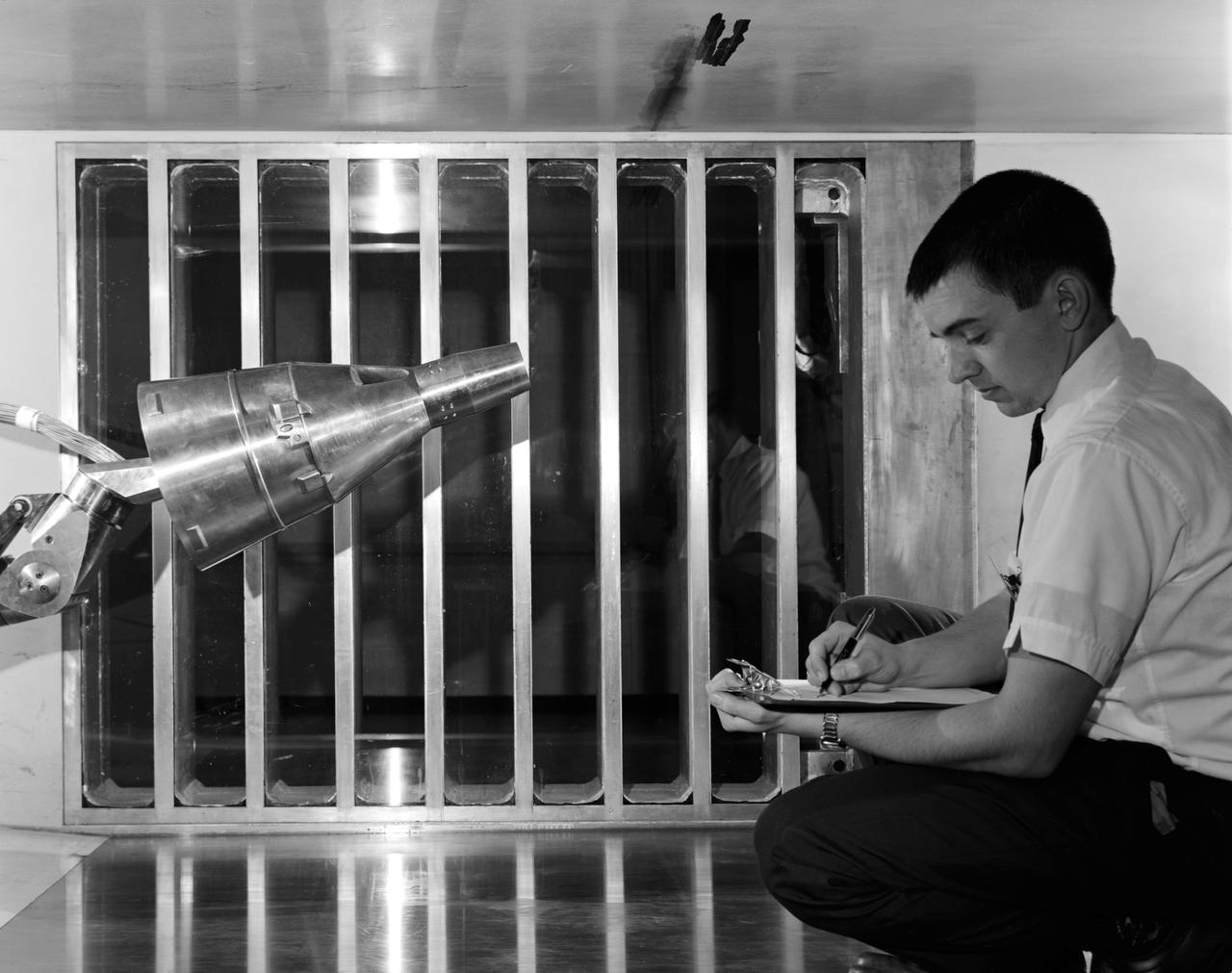
Gemini capsule being tested in Unitary Plan Wind Tunnel.
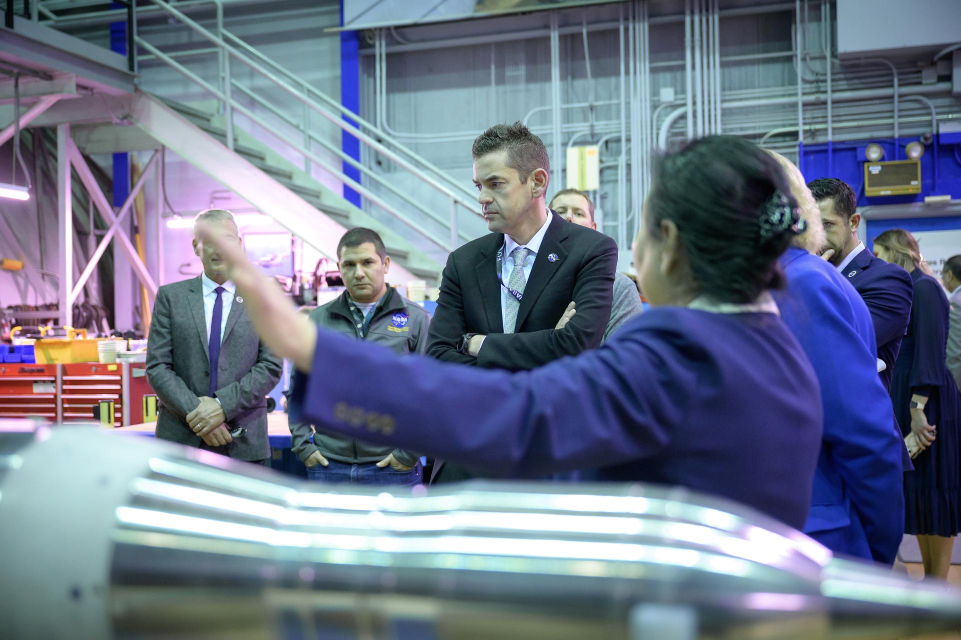
NASA Administrator Jared Isaacman listens to a presentation by wind tunnel staff in the Unitary Plan Wind Tunnel (UPWT) facility in N227.
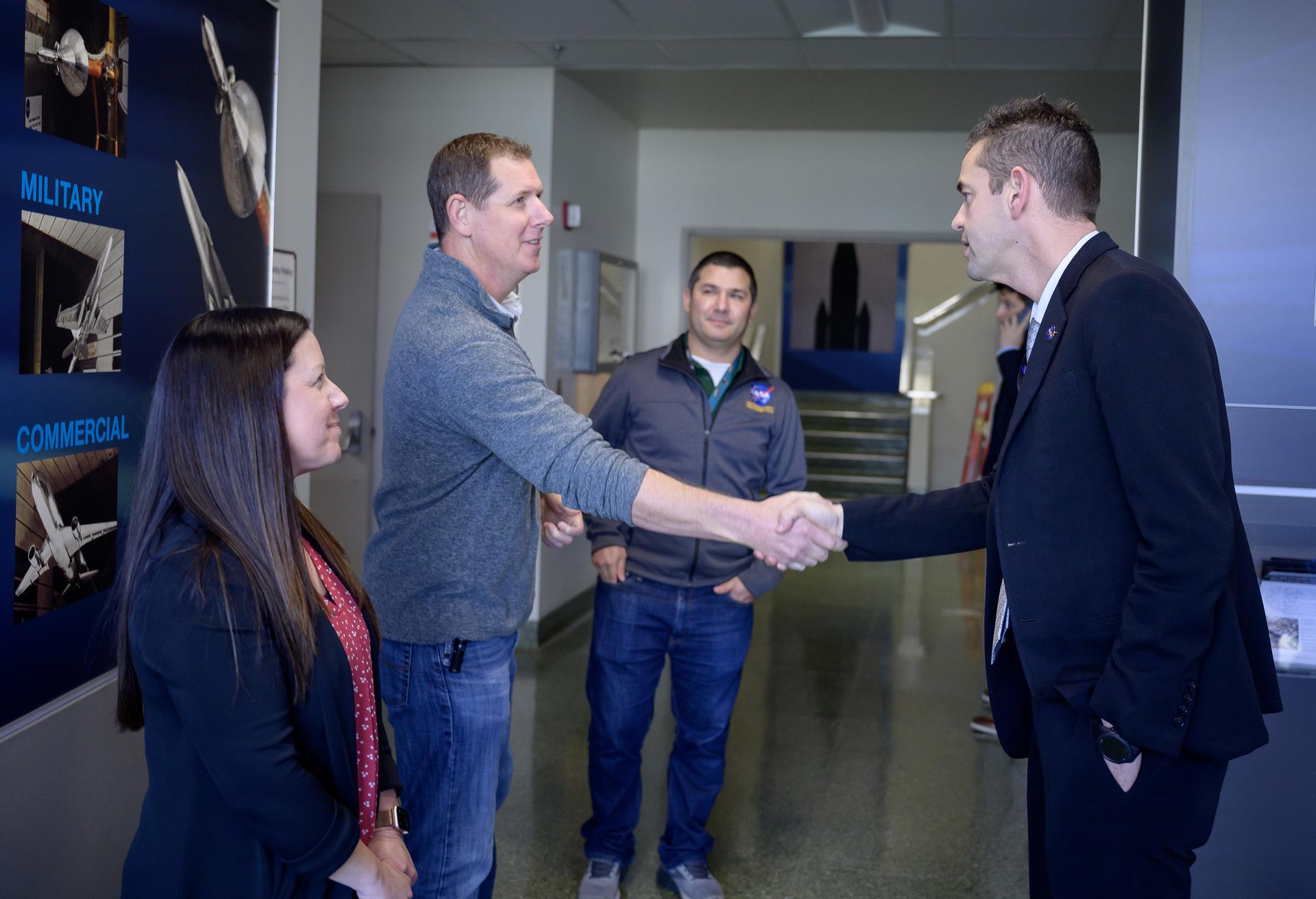
Wind tunnel staff Mike Treece and Wind Tunnel Division Chief Maureen Delgado greet NASA Administrator Jared Isaacman in the lobby of the Unitary Plan Wind Tunnel (UPWT) facility in N227.
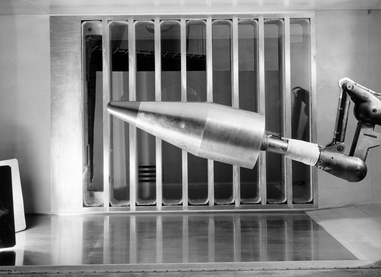
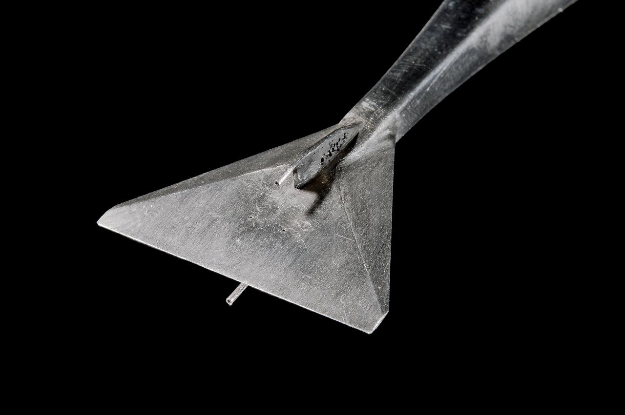
L57-700 In the reentry flight path of this nose cone model of a Jupiter Intermediate range ballistic missile (IRBM) was tested in the Unitary Plan Wind Tunnel. Photograph published in Engineer in Charge: A History of the Langley Aeronautical Laboratory, 1917-1958 by James R. Hansen. Page 475.
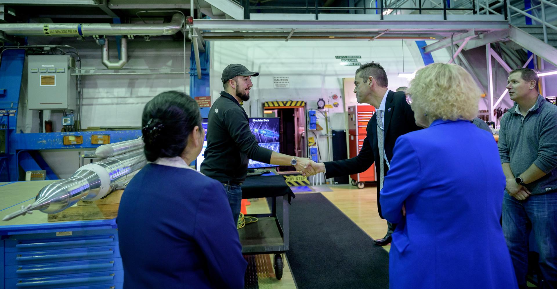
NASA Administrator Jared Isaacman meets wind tunnel staff during a tour of the Unitary Plan Wind Tunnel (UPWT) facility in N227.
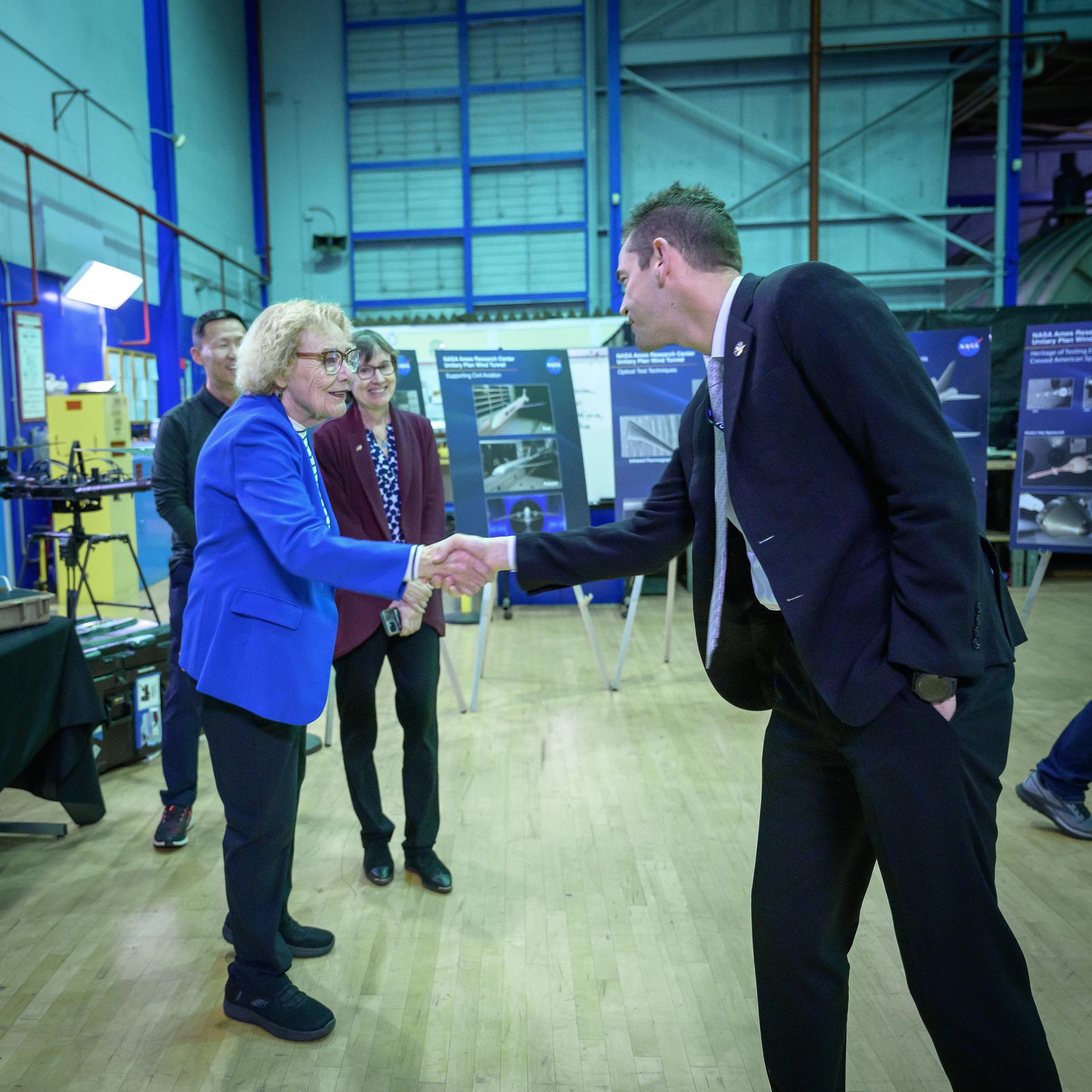
NASA Administrator Jared Isaacman meets Congresswoman Zoe Lofgren during a tour of the Unitary Plan Wind Tunnel (UPWT) facility in N227.
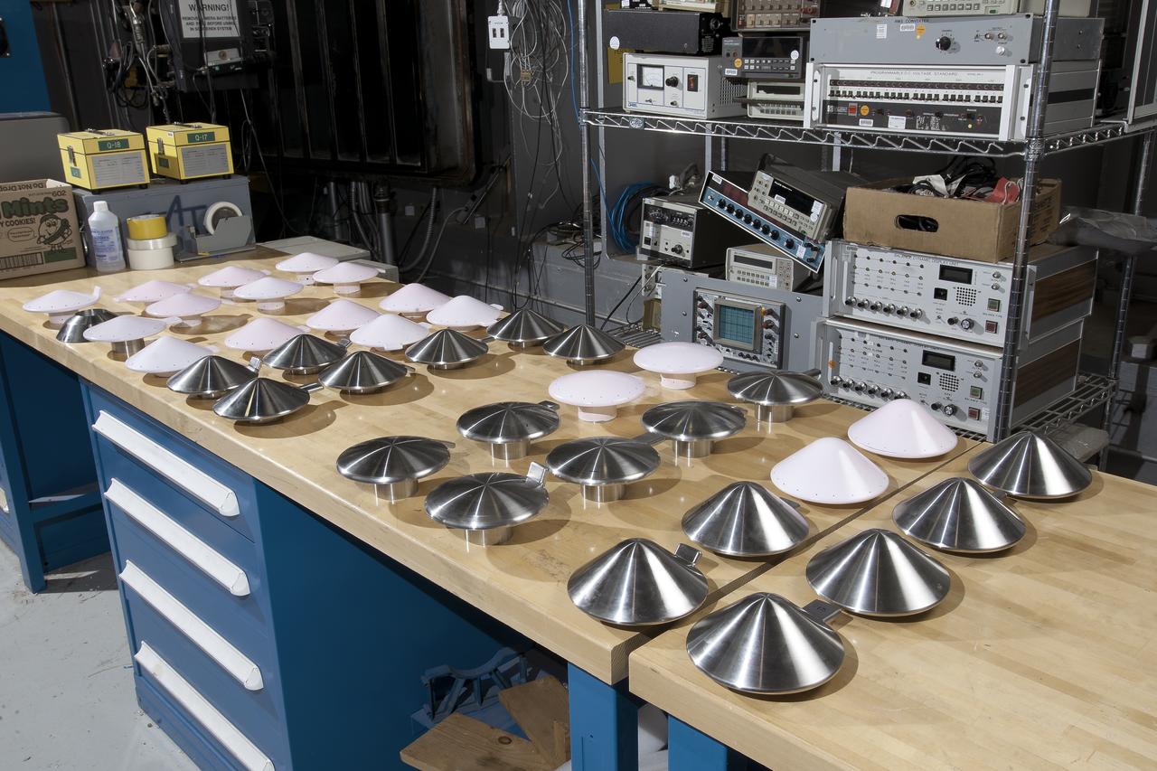
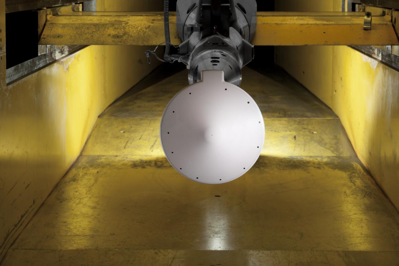
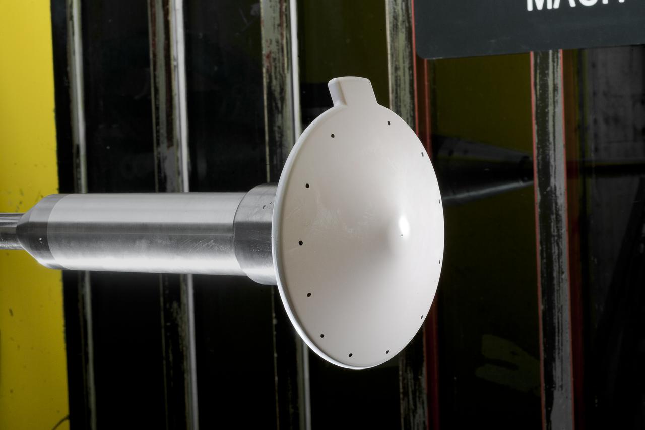
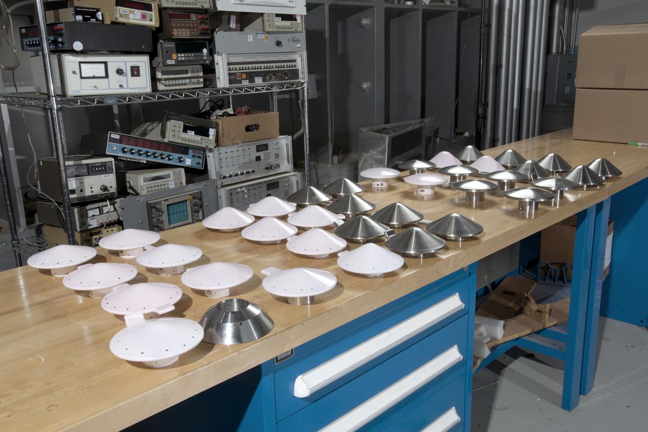
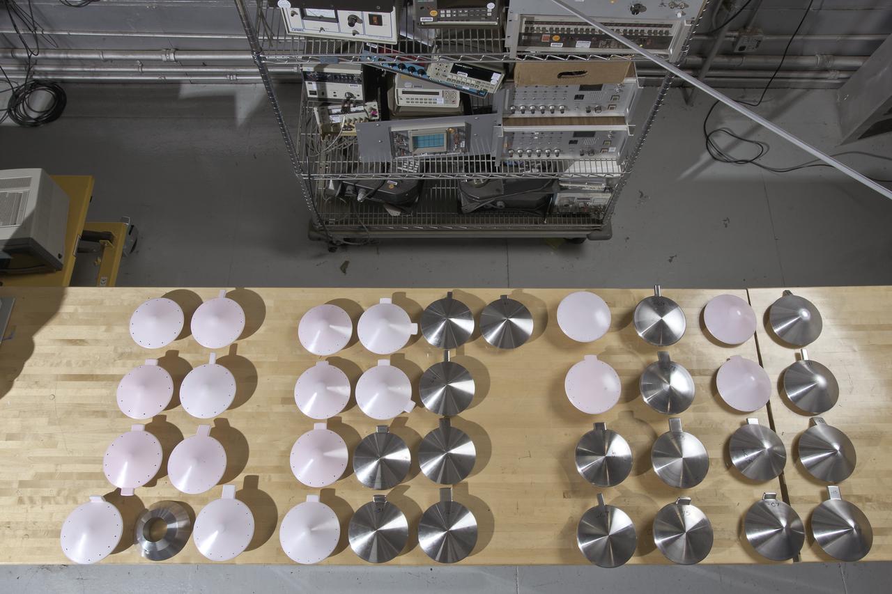
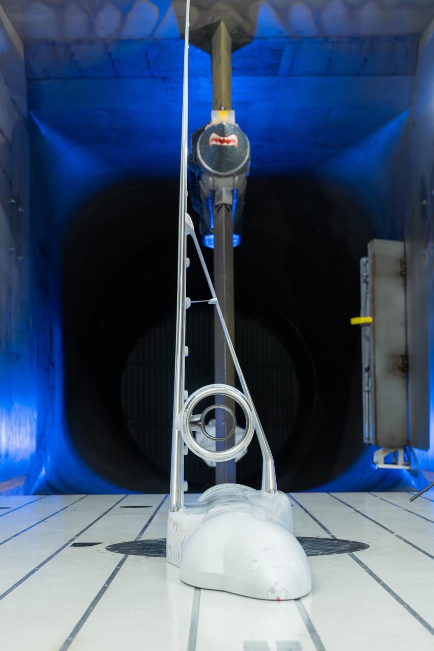
Test 1875 in Unitary Plan Wind Tunnel (UPWT) HIADS TTPM: Trim Tab study on various cone angled heat shields (TTPM) Technology Technical Performance Metric (HIADS) Hypersonic inflatable aerodynamic decelerators
Test 1875 in Unitary Plan Wind Tunnel (UPWT) HIADS TTPM: Trim Tab study on various cone angled heat shields (TTPM) Technology Technical Performance Metric (HIADS) Hypersonic inflatable aerodynamic decelerators
Test 1875 in Unitary Plan Wind Tunnel (UPWT) HIADS TTPM: Trim Tab study on various cone angled heat shields (TTPM) Technology Technical Performance Metric (HIADS) Hypersonic inflatable aerodynamic decelerators
Test 1875 in Unitary Plan Wind Tunnel (UPWT) HIADS TTPM: Trim Tab study on various cone angled heat shields (TTPM) Technology Technical Performance Metric (HIADS) Hypersonic inflatable aerodynamic decelerators
Test 1875 in Unitary Plan Wind Tunnel (UPWT) HIADS TTPM: Trim Tab study on various cone angled heat shields (TTPM) Technology Technical Performance Metric (HIADS) Hypersonic inflatable aerodynamic decelerators
Test 1875 in Unitary Plan Wind Tunnel (UPWT) HIADS TTPM: Trim Tab study on various cone angled heat shields (TTPM) Technology Technical Performance Metric (HIADS) Hypersonic inflatable aerodynamic decelerators
Test 1875 in Unitary Plan Wind Tunnel (UPWT) HIADS TTPM: Trim Tab study on various cone angled heat shields (TTPM) Technology Technical Performance Metric (HIADS) Hypersonic inflatable aerodynamic decelerators
Researcher checks model of Project Fire Reentry package to be tested in Unitary Plan Wind Tunnel. Project FIRE (Flight Investigation Reentry Environment) studied the effects of reentry heating on spacecraft materials. It involved both wind tunnel and flight tests, although the majority were tests with Atlas rockets and recoverable reentry packages. These flight tests took place at Cape Canaveral in Florida. Wind tunnel tests were made in several Langley tunnels including the Unitary Plan Wind Tunnel, the 8-foot High-Temperature Tunnel and the 9x6-Foot Thermal Structures Tunnel. Photo published in book "A Century at Langley" by Joseph Chambers pg. 92
Stage Separation Test of the Space Launch System(SLS) in the Langley Unitary Plan Wind Tunnel (UPWT). The model used High Pressure air blown through the solid rocket boosters. (SRB) to simulate the booster separation motors (BSM) firing.
Stage Separation Test of the Space Launch System(SLS) in the Langley Unitary Plan Wind Tunnel (UPWT). The model used High Pressure air blown through the solid rocket boosters. (SRB) to simulate the booster separation motors (BSM) firing.
Stage Separation Test of the Space Launch System(SLS) in the Langley Unitary Plan Wind Tunnel (UPWT). The model used High Pressure air blown through the solid rocket boosters. (SRB) to simulate the booster separation motors (BSM) firing.
Stage Separation Test of the Space Launch System(SLS) in the Langley Unitary Plan Wind Tunnel (UPWT). The model used High Pressure air blown through the solid rocket boosters. (SRB) to simulate the booster separation motors (BSM) firing.
Stage Separation Test of the Space Launch System(SLS) in the Langley Unitary Plan Wind Tunnel (UPWT). The model used High Pressure air blown through the solid rocket boosters. (SRB) to simulate the booster separation motors (BSM) firing.
Stage Separation Test of the Space Launch System(SLS) in the Langley Unitary Plan Wind Tunnel (UPWT). The model used High Pressure air blown through the solid rocket boosters. (SRB) to simulate the booster separation motors (BSM) firing.
Stage Separation Test of the Space Launch System(SLS) in the Langley Unitary Plan Wind Tunnel (UPWT). The model used High Pressure air blown through the solid rocket boosters. (SRB) to simulate the booster separation motors (BSM) firing.
Stage Separation Test of the Space Launch System(SLS) in the Langley Unitary Plan Wind Tunnel (UPWT). The model used High Pressure air blown through the solid rocket boosters. (SRB) to simulate the booster separation motors (BSM) firing.
Stage Separation Test of the Space Launch System(SLS) in the Langley Unitary Plan Wind Tunnel (UPWT). The model used High Pressure air blown through the solid rocket boosters. (SRB) to simulate the booster separation motors (BSM) firing.

Stage Separation Test of the Space Launch System(SLS) in the Langley Unitary Plan Wind Tunnel (UPWT). The model used High Pressure air blown through the solid rocket boosters. (SRB) to simulate the booster separation motors (BSM) firing.
Stage Separation Test of the Space Launch System(SLS) in the Langley Unitary Plan Wind Tunnel (UPWT). The model used High Pressure air blown through the solid rocket boosters. (SRB) to simulate the booster separation motors (BSM) firing.
Stage Separation Test of the Space Launch System(SLS) in the Langley Unitary Plan Wind Tunnel (UPWT). The model used High Pressure air blown through the solid rocket boosters. (SRB) to simulate the booster separation motors (BSM) firing.
Stage Separation Test of the Space Launch System(SLS) in the Langley Unitary Plan Wind Tunnel (UPWT). The model used High Pressure air blown through the solid rocket boosters. (SRB) to simulate the booster separation motors (BSM) firing.

Stage Separation Test of the Space Launch System(SLS) in the Langley Unitary Plan Wind Tunnel (UPWT). The model used High Pressure air blown through the solid rocket boosters. (SRB) to simulate the booster separation motors (BSM) firing.
Stage Separation Test of the Space Launch System(SLS) in the Langley Unitary Plan Wind Tunnel (UPWT). The model used High Pressure air blown through the solid rocket boosters. (SRB) to simulate the booster separation motors (BSM) firing.
Stage Separation Test of the Space Launch System(SLS) in the Langley Unitary Plan Wind Tunnel (UPWT). The model used High Pressure air blown through the solid rocket boosters. (SRB) to simulate the booster separation motors (BSM) firing.
Stage Separation Test of the Space Launch System(SLS) in the Langley Unitary Plan Wind Tunnel (UPWT). The model used High Pressure air blown through the solid rocket boosters. (SRB) to simulate the booster separation motors (BSM) firing.
Stage Separation Test of the Space Launch System(SLS) in the Langley Unitary Plan Wind Tunnel (UPWT). The model used High Pressure air blown through the solid rocket boosters. (SRB) to simulate the booster separation motors (BSM) firing.
Stage Separation Test of the Space Launch System(SLS) in the Langley Unitary Plan Wind Tunnel (UPWT). The model used High Pressure air blown through the solid rocket boosters. (SRB) to simulate the booster separation motors (BSM) firing.
Stage Separation Test of the Space Launch System(SLS) in the Langley Unitary Plan Wind Tunnel (UPWT). The model used High Pressure air blown through the solid rocket boosters. (SRB) to simulate the booster separation motors (BSM) firing.
Stage Separation Test of the Space Launch System(SLS) in the Langley Unitary Plan Wind Tunnel (UPWT). The model used High Pressure air blown through the solid rocket boosters. (SRB) to simulate the booster separation motors (BSM) firing.
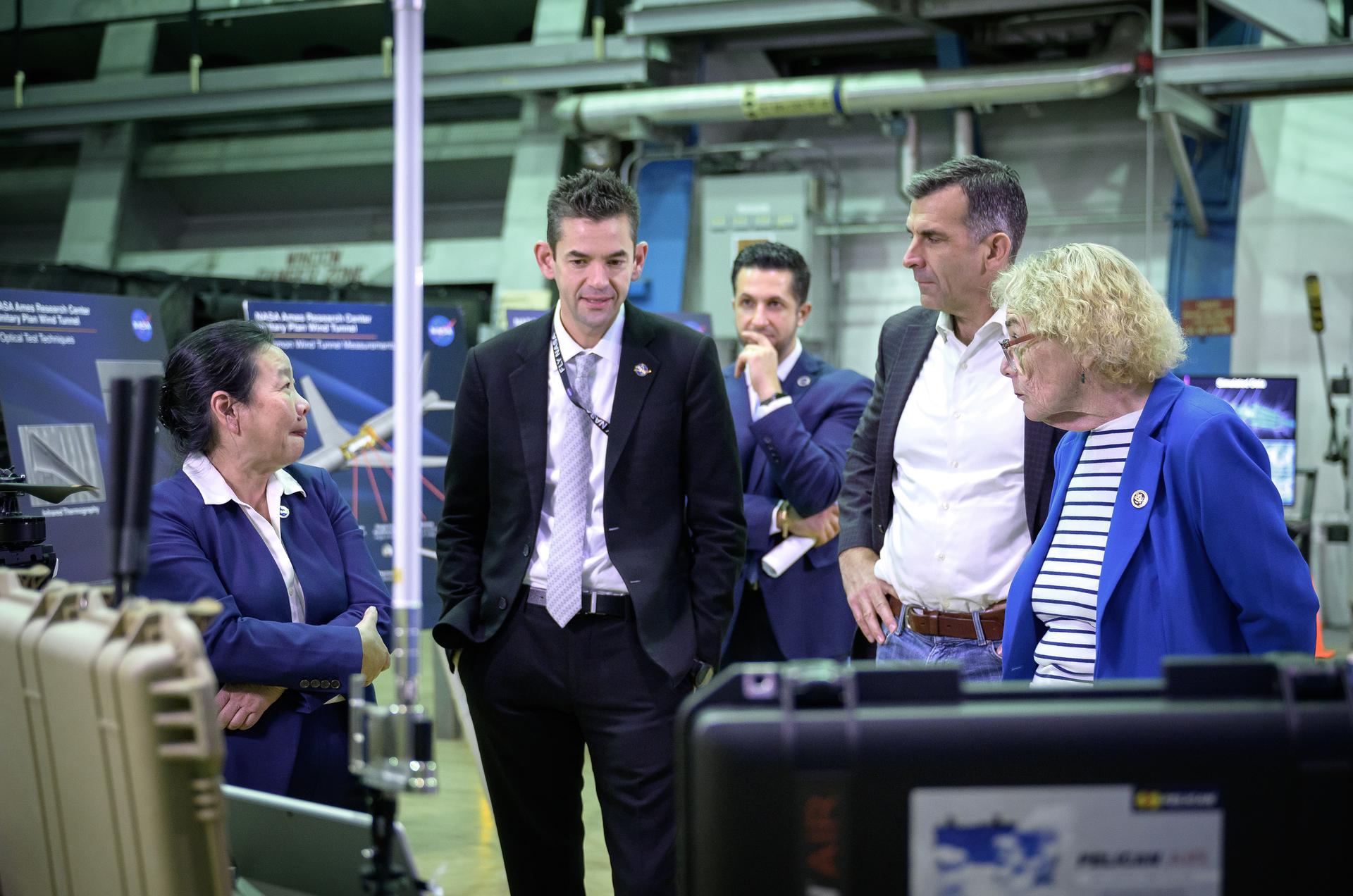
Director of Aeronautics Huy Tran, left, NASA Administrator Jared Isaacman, Associate Center Director Amir Deylami, back, Congressman Sam Liccardo, and Congresswoman Zoe Lofgren, right, tour the Unitary Plan Wind Tunnel (UPWT) facility in N227.
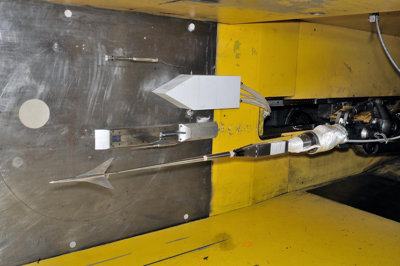
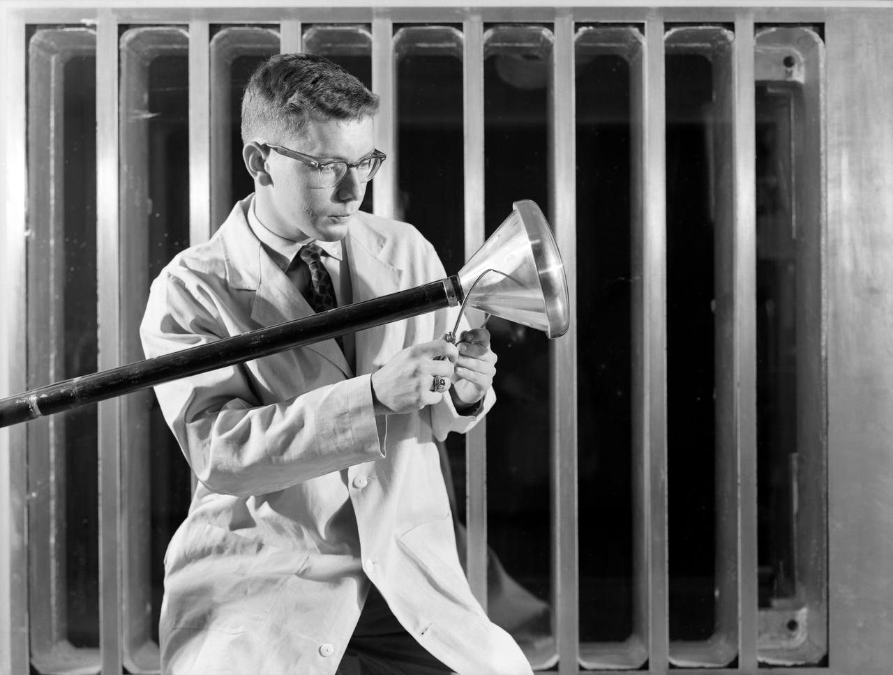
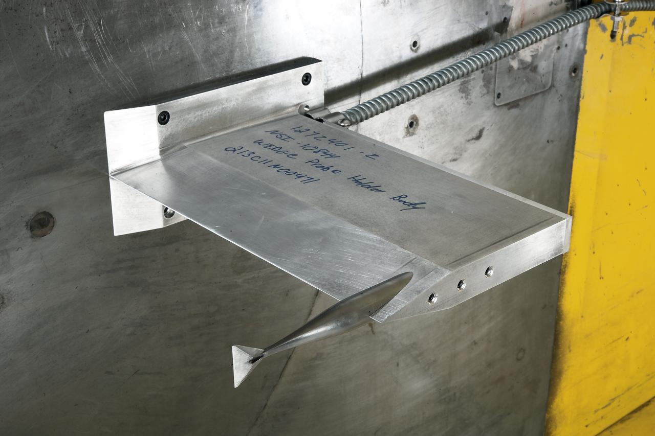
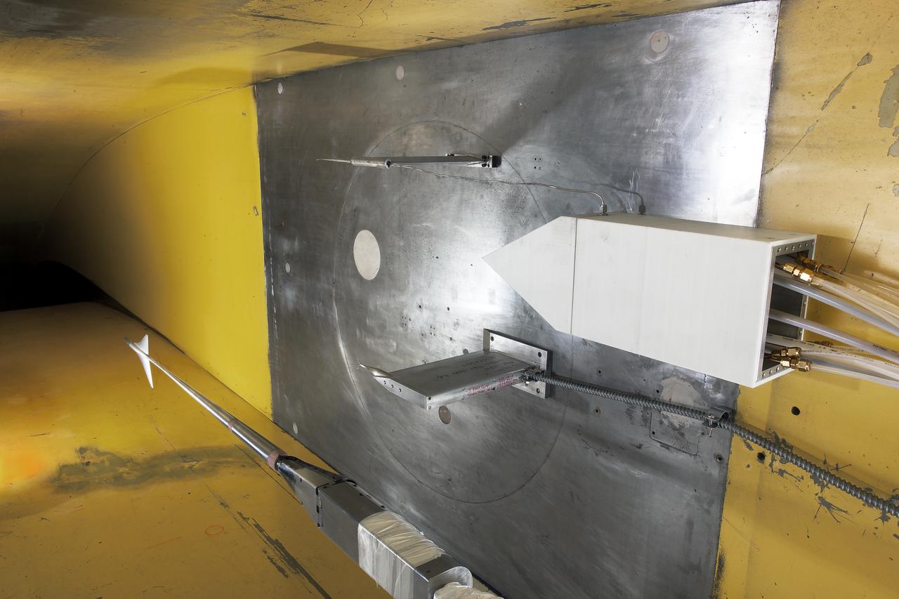
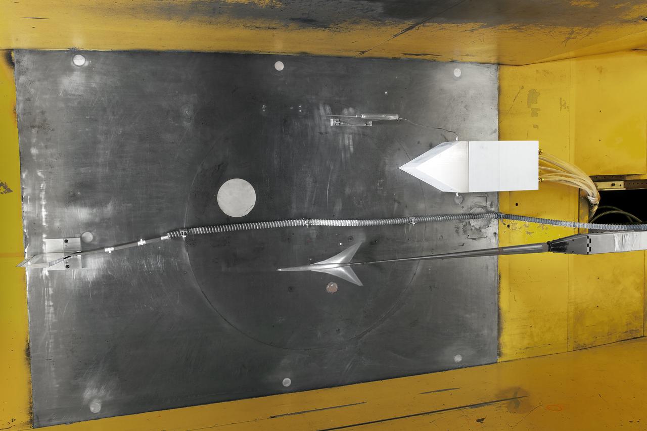
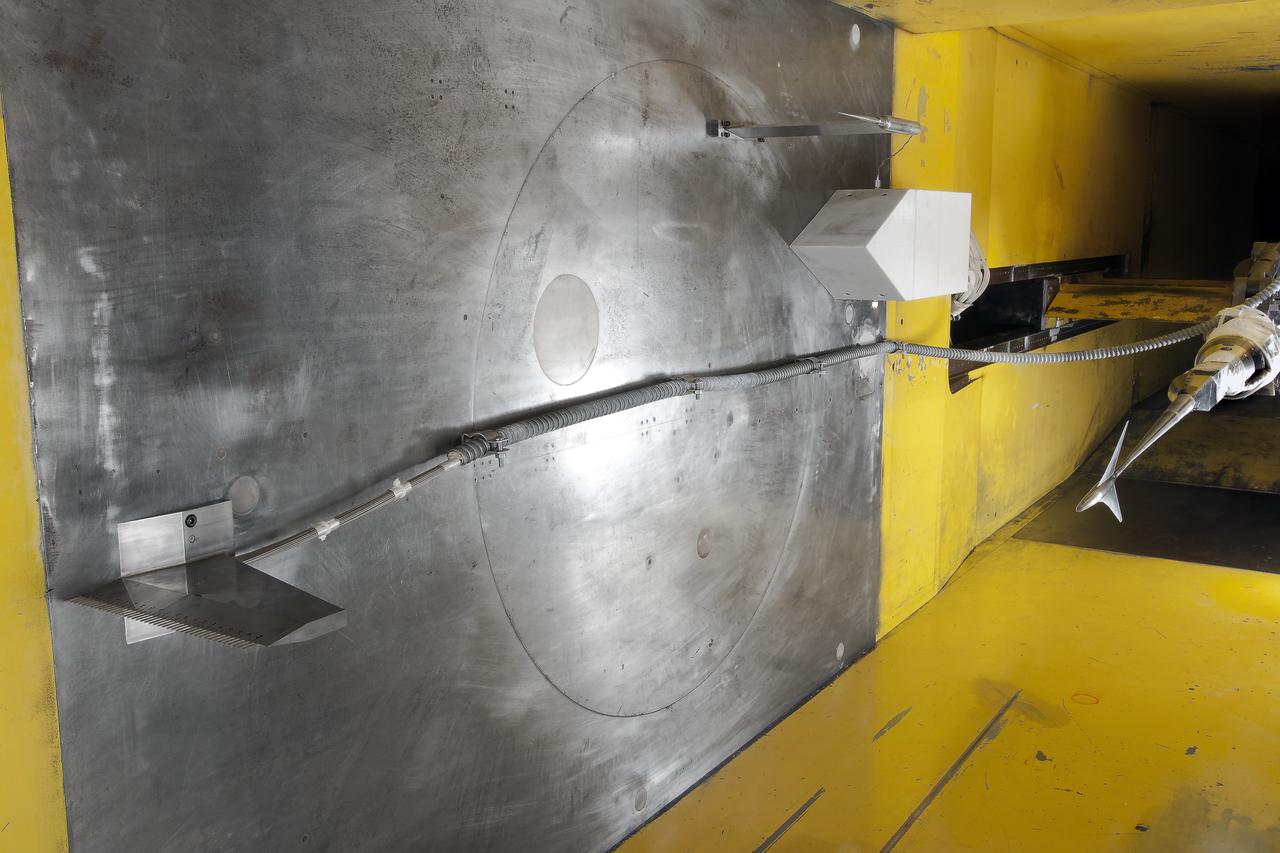
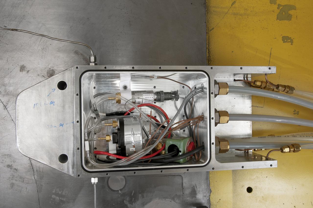
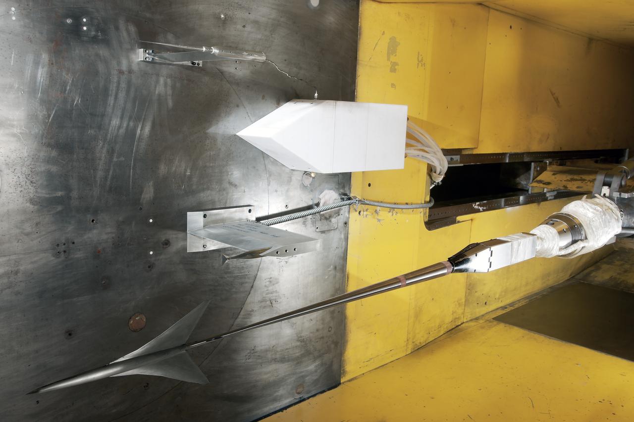
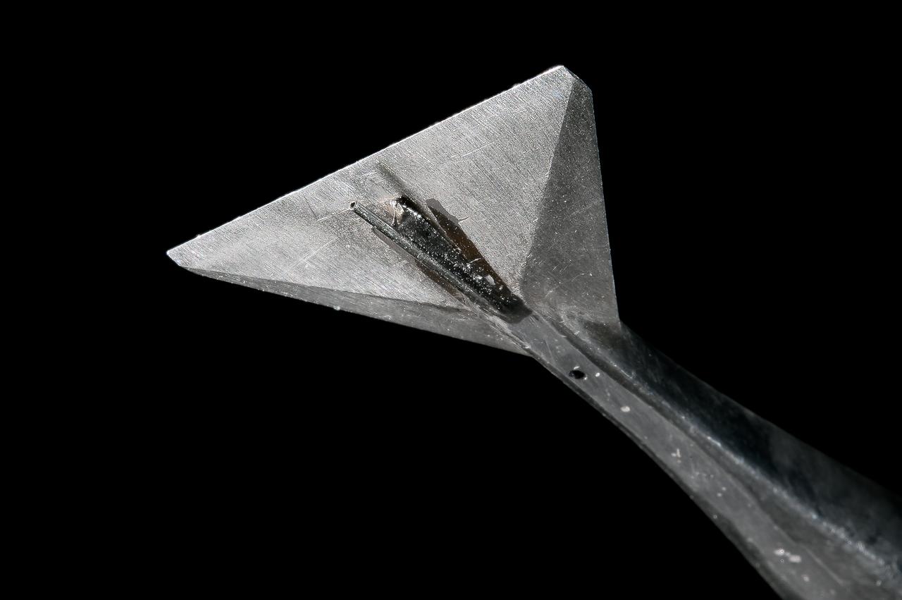
UPWT Test 1998 Continuous Data Sonic Boom Test. Sonic Boom Hardward Mounted in the Langley Unitary Plan wind Tunnel(UPWT). Conical survey probes, wedge probe, and wind tunnel wall boundary layer rake. Rectangular box with wedge front end is a transducer box to that held pressure transducer for the conical probes.
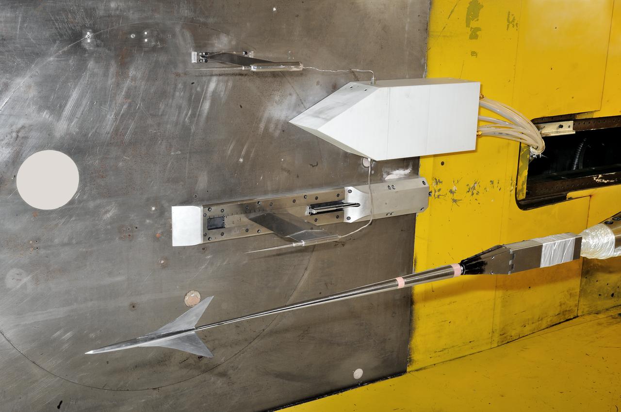
UPWT Test 1998 Continuous Data Sonic Boom Test. Sonic Boom Hardward Mounted in the Langley Unitary Plan wind Tunnel(UPWT). Conical survey probes, wedge probe, and wind tunnel wall boundary layer rake. Rectangular box with wedge front end is a transducer box to that held pressure transducer for the conical probes.
UPWT Test 1998 Continuous Data Sonic Boom Test. Sonic Boom Hardward Mounted in the Langley Unitary Plan wind Tunnel(UPWT). Conical survey probes, wedge probe, and wind tunnel wall boundary layer rake. Rectangular box with wedge front end is a transducer box to that held pressure transducer for the conical probes.
UPWT Test 1998 Continuous Data Sonic Boom Test. Sonic Boom Hardward Mounted in the Langley Unitary Plan wind Tunnel(UPWT). Conical survey probes, wedge probe, and wind tunnel wall boundary layer rake. Rectangular box with wedge front end is a transducer box to that held pressure transducer for the conical probes.
UPWT Test 1998 Continuous Data Sonic Boom Test. Sonic Boom Hardward Mounted in the Langley Unitary Plan wind Tunnel(UPWT). Conical survey probes, wedge probe, and wind tunnel wall boundary layer rake. Rectangular box with wedge front end is a transducer box to that held pressure transducer for the conical probes.
UPWT Test 1998 Continuous Data Sonic Boom Test. Sonic Boom Hardward Mounted in the Langley Unitary Plan wind Tunnel(UPWT). Conical survey probes, wedge probe, and wind tunnel wall boundary layer rake. Rectangular box with wedge front end is a transducer box to that held pressure transducer for the conical probes.

UPWT Test 1998 Continuous Data Sonic Boom Test. Sonic Boom Hardward Mounted in the Langley Unitary Plan wind Tunnel(UPWT). Conical survey probes, wedge probe, and wind tunnel wall boundary layer rake. Rectangular box with wedge front end is a transducer box to that held pressure transducer for the conical probes.
UPWT Test 1998 Continuous Data Sonic Boom Test. Sonic Boom Hardward Mounted in the Langley Unitary Plan wind Tunnel(UPWT). Conical survey probes, wedge probe, and wind tunnel wall boundary layer rake. Rectangular box with wedge front end is a transducer box to that held pressure transducer for the conical probes.
UPWT Test 1998 Continuous Data Sonic Boom Test. Sonic Boom Hardward Mounted in the Langley Unitary Plan wind Tunnel(UPWT). Conical survey probes, wedge probe, and wind tunnel wall boundary layer rake. Rectangular box with wedge front end is a transducer box to that held pressure transducer for the conical probes.
UPWT Test 1998 Continuous Data Sonic Boom Test. Sonic Boom Hardward Mounted in the Langley Unitary Plan wind Tunnel(UPWT). Conical survey probes, wedge probe, and wind tunnel wall boundary layer rake. Rectangular box with wedge front end is a transducer box to that held pressure transducer for the conical probes.
UPWT Test 1998 Continuous Data Sonic Boom Test. Sonic Boom Hardward Mounted in the Langley Unitary Plan wind Tunnel(UPWT). Conical survey probes, wedge probe, and wind tunnel wall boundary layer rake. Rectangular box with wedge front end is a transducer box to that held pressure transducer for the conical probes.
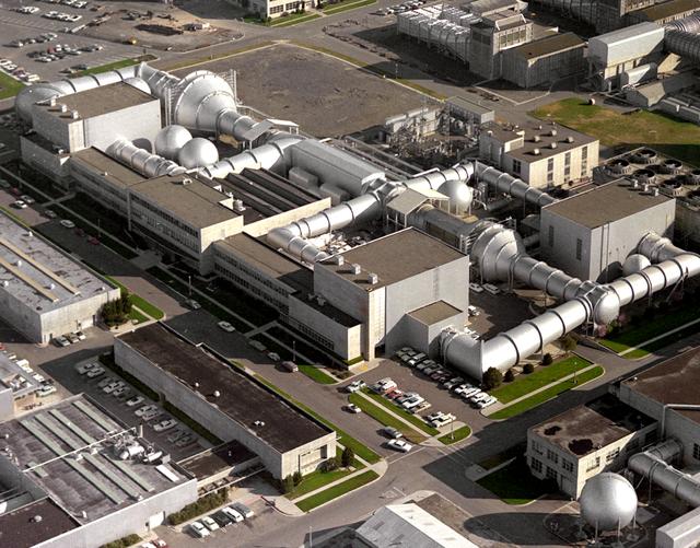
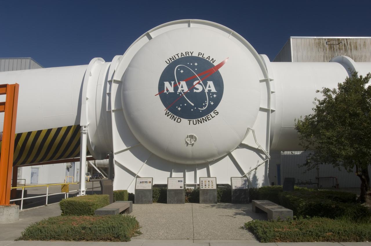
Aerial view of Unitary Plan Wind Tunnel complex with NASA insignia
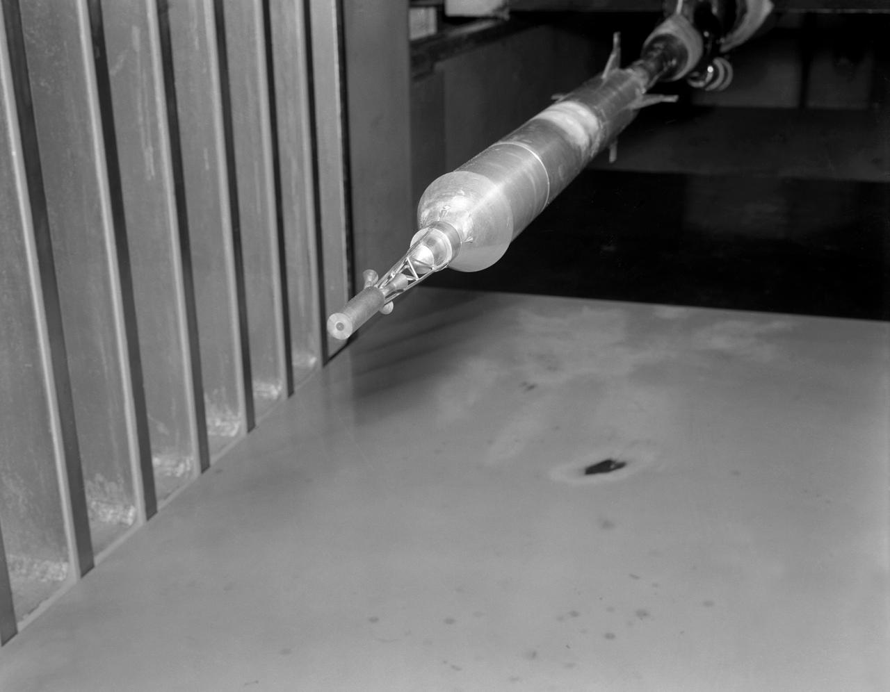
Model of Mercury being tested in the Unitary Plan Wind Tunnel.
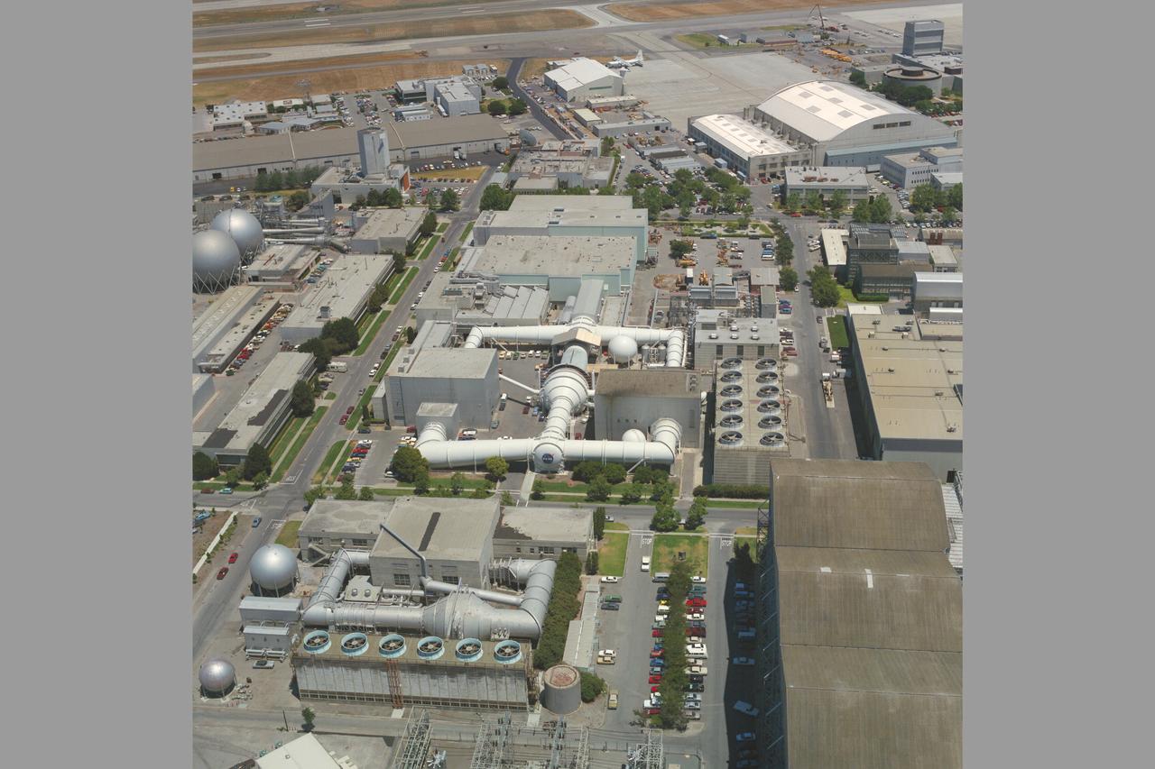
Aerial view of Ames Unitary Plan Wind Tunnel complex N-227
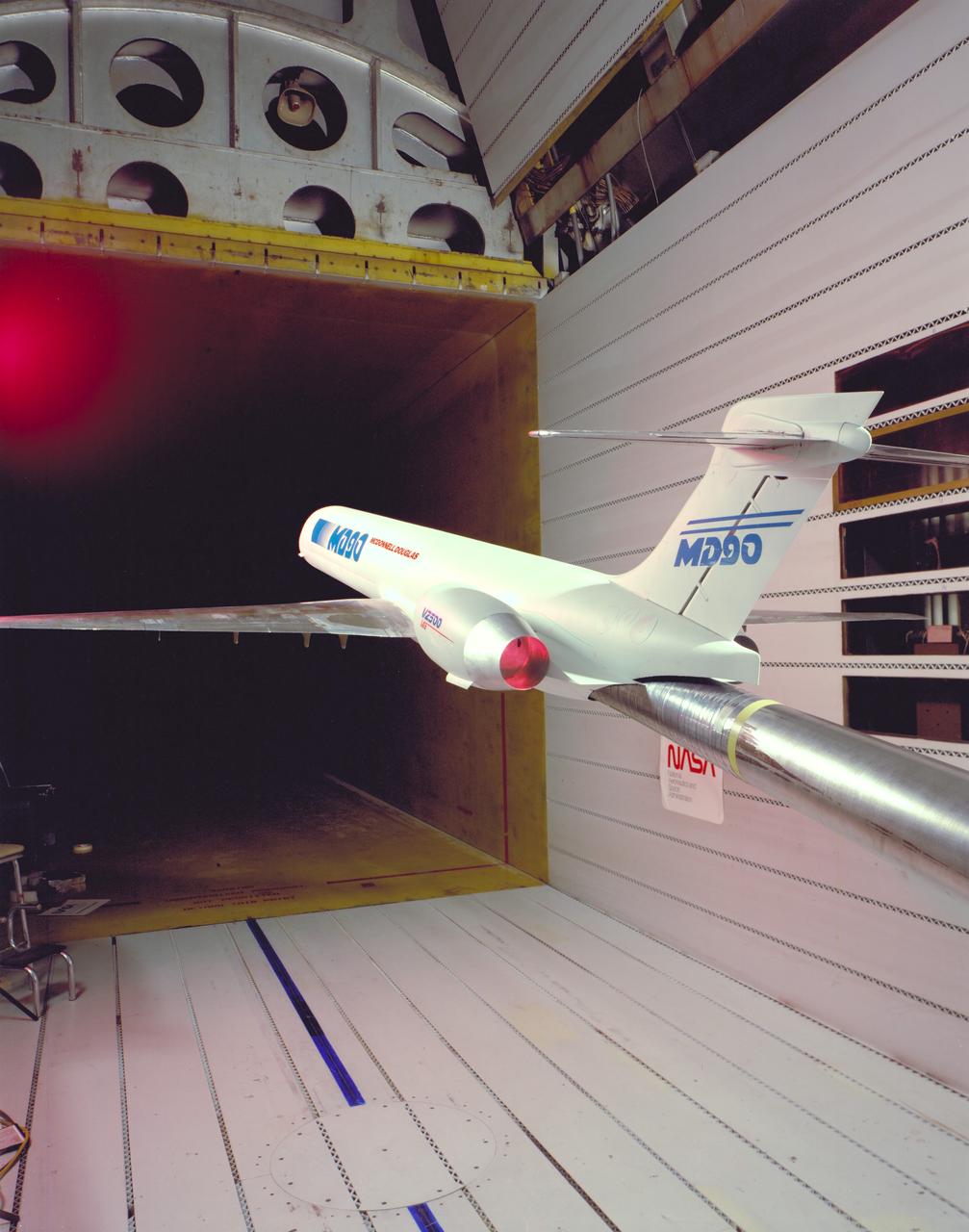
MD-90 Model in NASA Ames Research Center 11ft. Transonic Wind Tunnel part of the Unitary Plan Wind Tunnel Complex Test-091-1-11
0.4% Scale (SLS) Space Launch System Model Test In NASA LaRC Unitary Plan Wind Tunnel
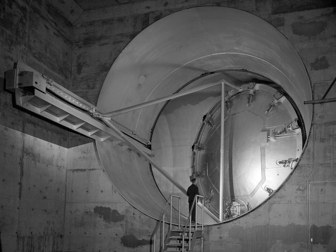
N-227 Unitary Plan Wind Tunnel Modification Project - diffuser & contraction vanes
Model of Mercury (Redstone booster) carrying the spacecraft in the Unitary Plan wind tunnel for testing.
0.4% Scale (SLS) Space Launch System Model Test In NASA LaRC Unitary Plan Wind Tunnel
0.4% Scale (SLS) Space Launch System Model Test In NASA LaRC Unitary Plan Wind Tunnel
0.4% Scale (SLS) Space Launch System Model Test In NASA LaRC Unitary Plan Wind Tunnel
0.4% Scale (SLS) Space Launch System Model Test In NASA LaRC Unitary Plan Wind Tunnel

Model of Mercury (Redstone booster) carrying the spacecraft in the Unitary Plan wind tunnel for testing.
0.4% Scale (SLS) Space Launch System Model Test In NASA LaRC Unitary Plan Wind Tunnel
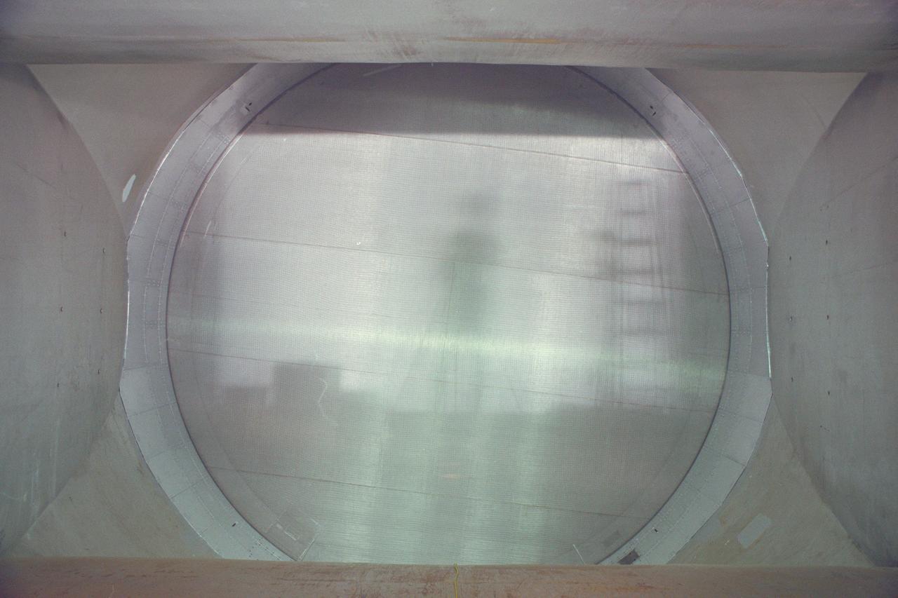
N-227 Unitary Plan Wind Tunnel Modification Project - diffuser & contraction vanes (image show reflection of photographer on vane)
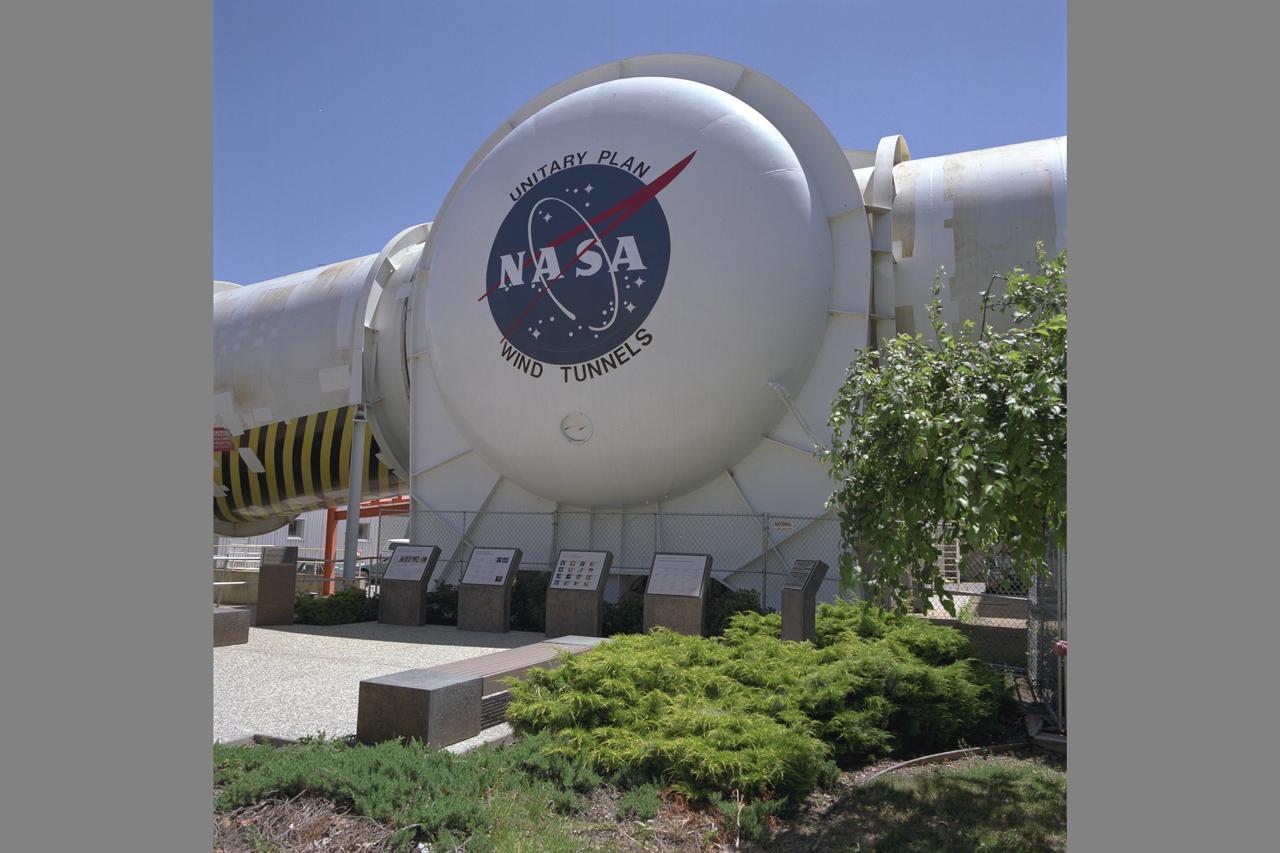
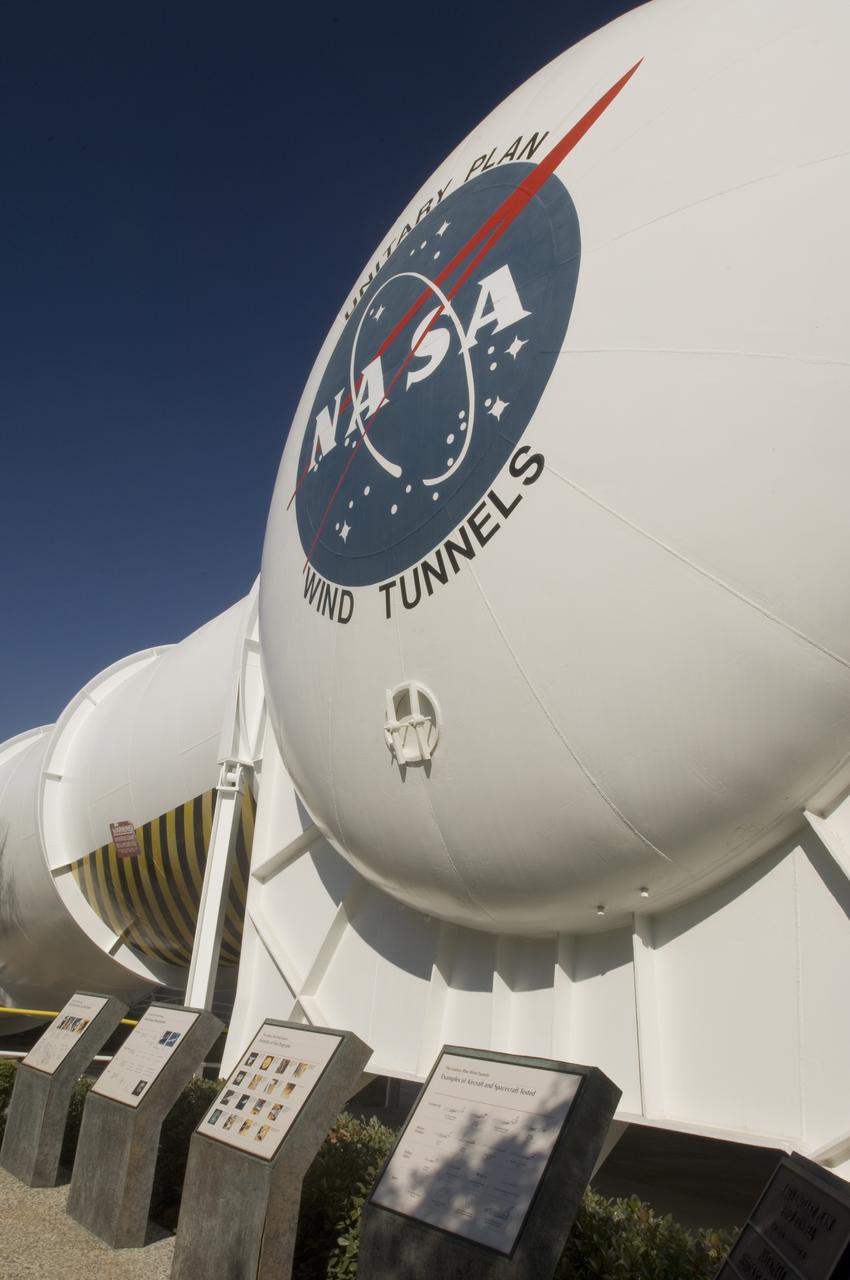
Unitary Plan Wind Tunnel N-227 (new) NASA Logo with Unitary International Historic Mechanical Engineering Landmark commemorative plaques in front. Date: June 16, 1998 Photographer: Tom Trower
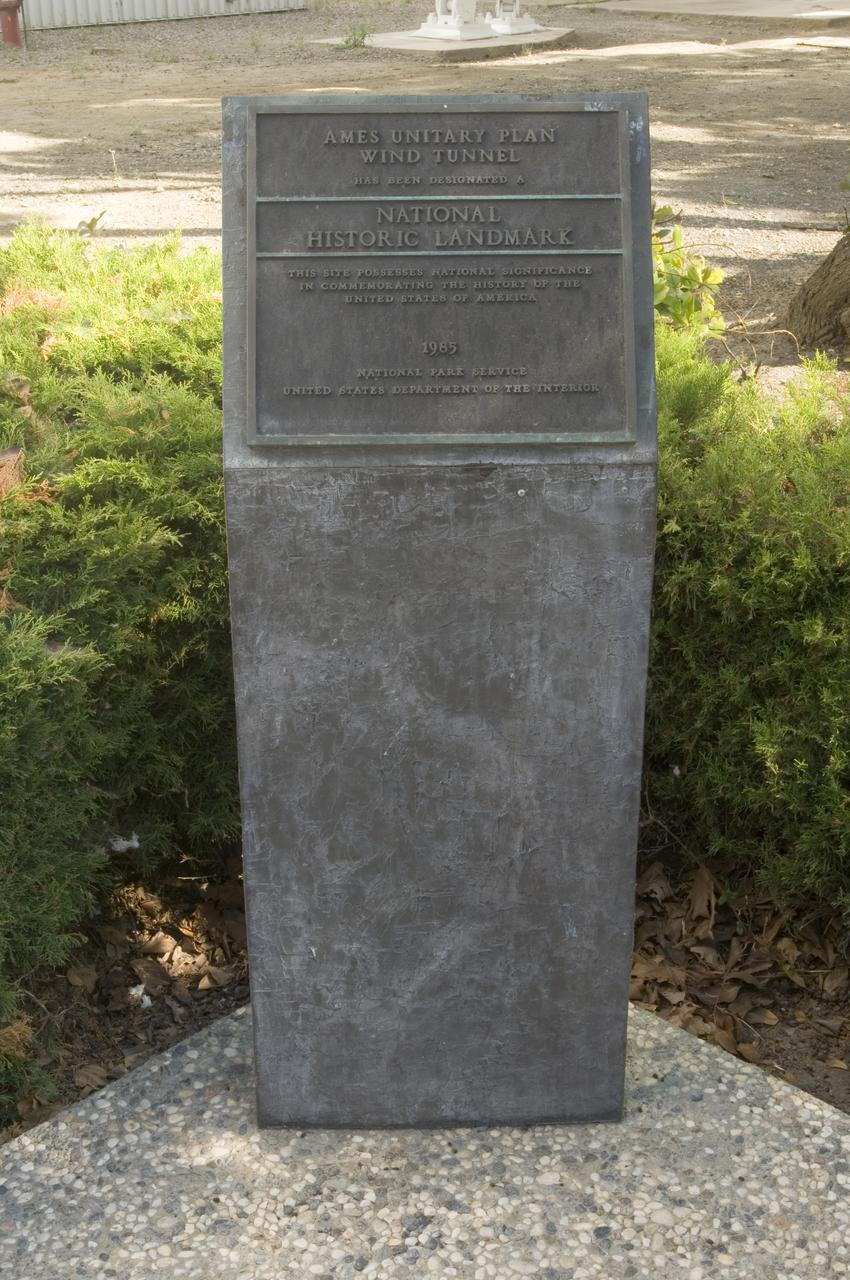
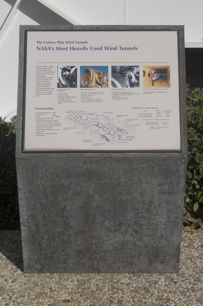
Ames and Moffett Field (MFA) historical sites and memorials Unitary Plan Wind Tunned plaza; display and historical site plaques with the NASA logo on the Wind Tunnel valve as a backdrop. Plaque depicts that Ames Unitary Plan Wind Tunnel has been designated a National Historic Landmark by the National Park Service, United States Department of the Interior 1985 The plaque reads; This site possesses national significance in commemorating the history of the United States of America. That ceremony took place on September 12, 1990
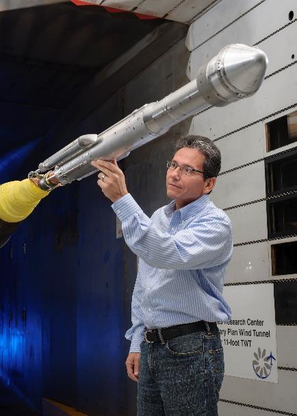
An engineer works with a model of a United Launch Alliance Atlas V rocket with a Boeing CST-100 Starliner capsule inside a wind tunnel at NASA's Ames Research Center in California. The Starliner/Atlas V system is under development by Boeing and ULA in partnership with NASA's Commercial Crew Program to launch astronauts to the International Space Station.
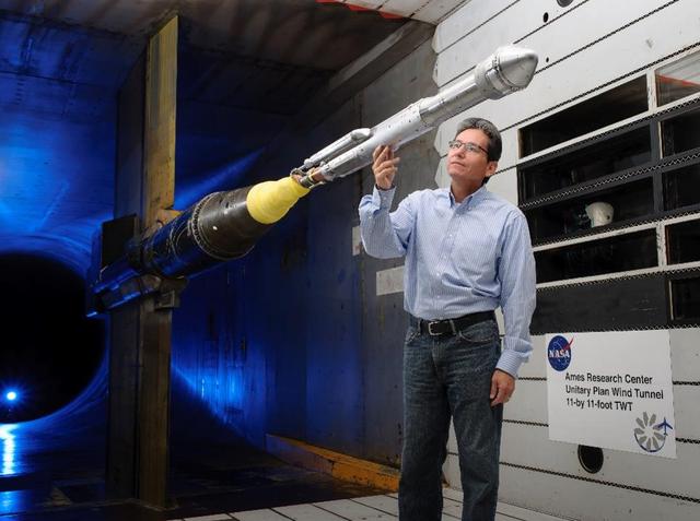
An engineer works with a model of a United Launch Alliance Atlas V rocket with a Boeing CST-100 Starliner capsule inside a wind tunnel at NASA's Ames Research Center in California. The Starliner/Atlas V system is under development by Boeing and ULA in partnership with NASA's Commercial Crew Program to launch astronauts to the International Space Station.
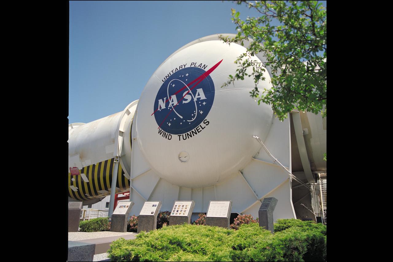
N-227 Unitary Plan Wind Tunnel with NASA 'Meatball' insignia over looking the National Historical Landmark sites' commemorative plaques
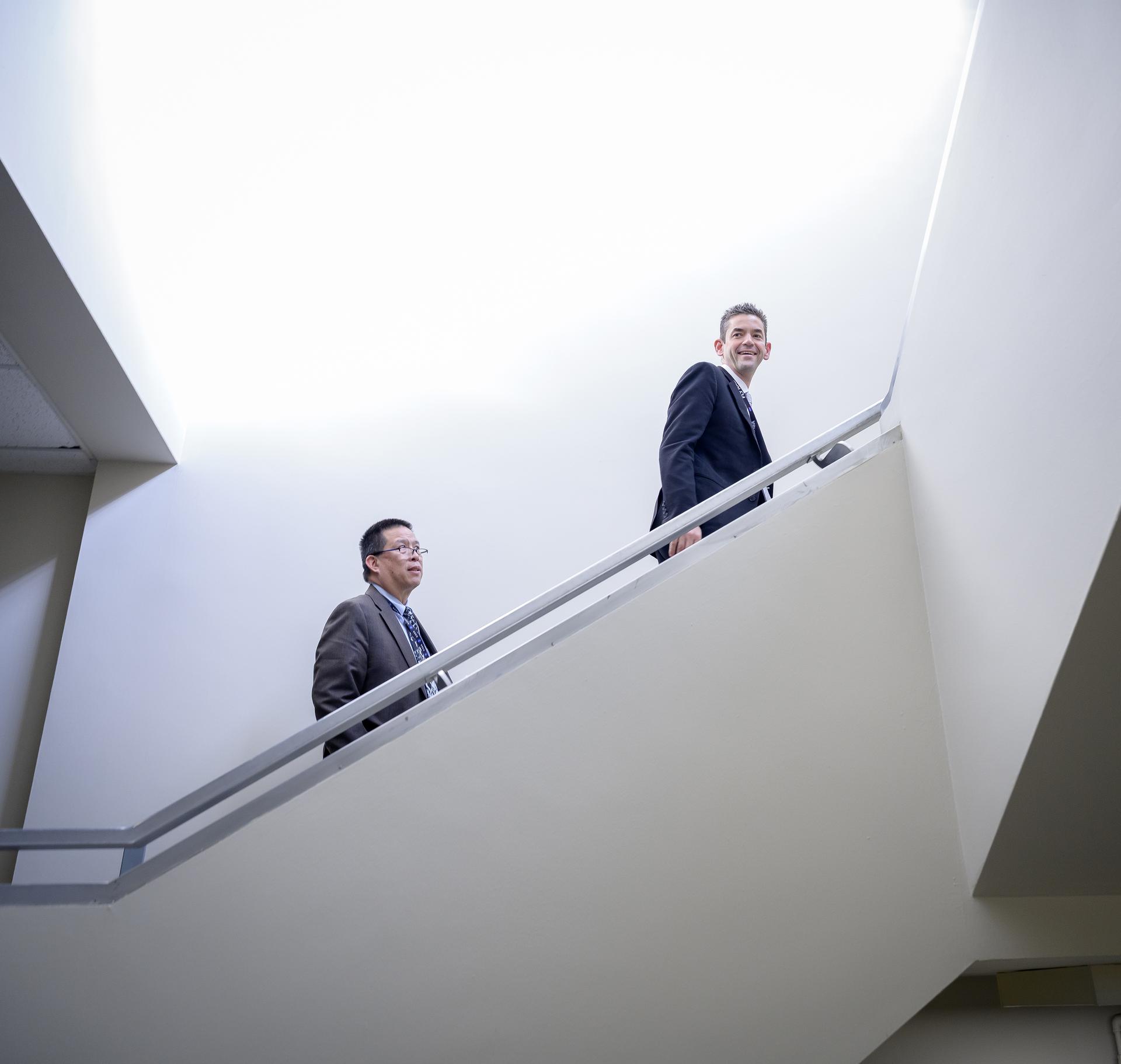
NASA Administrator Jared Isaacman, right, and Center Director Eugene Tu tour the Unitary Plan Wind Tunnel (UPWT) facility in N227.
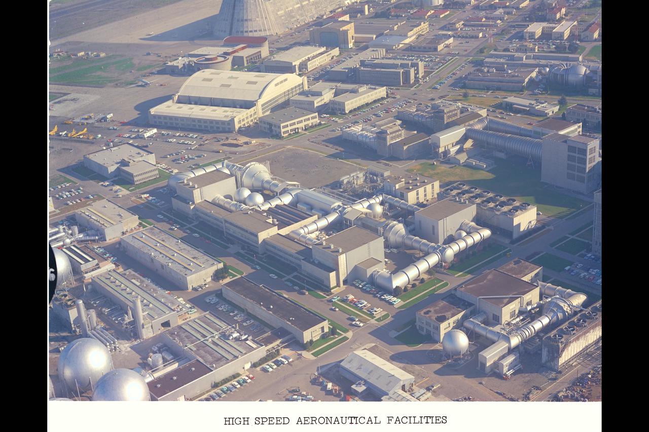
Aerial Survey of Ames Research Center centered on the Unitary Plan Wind Tunnel Complex and High Speed Aerodynamic Facilities (used in Bicentennial)
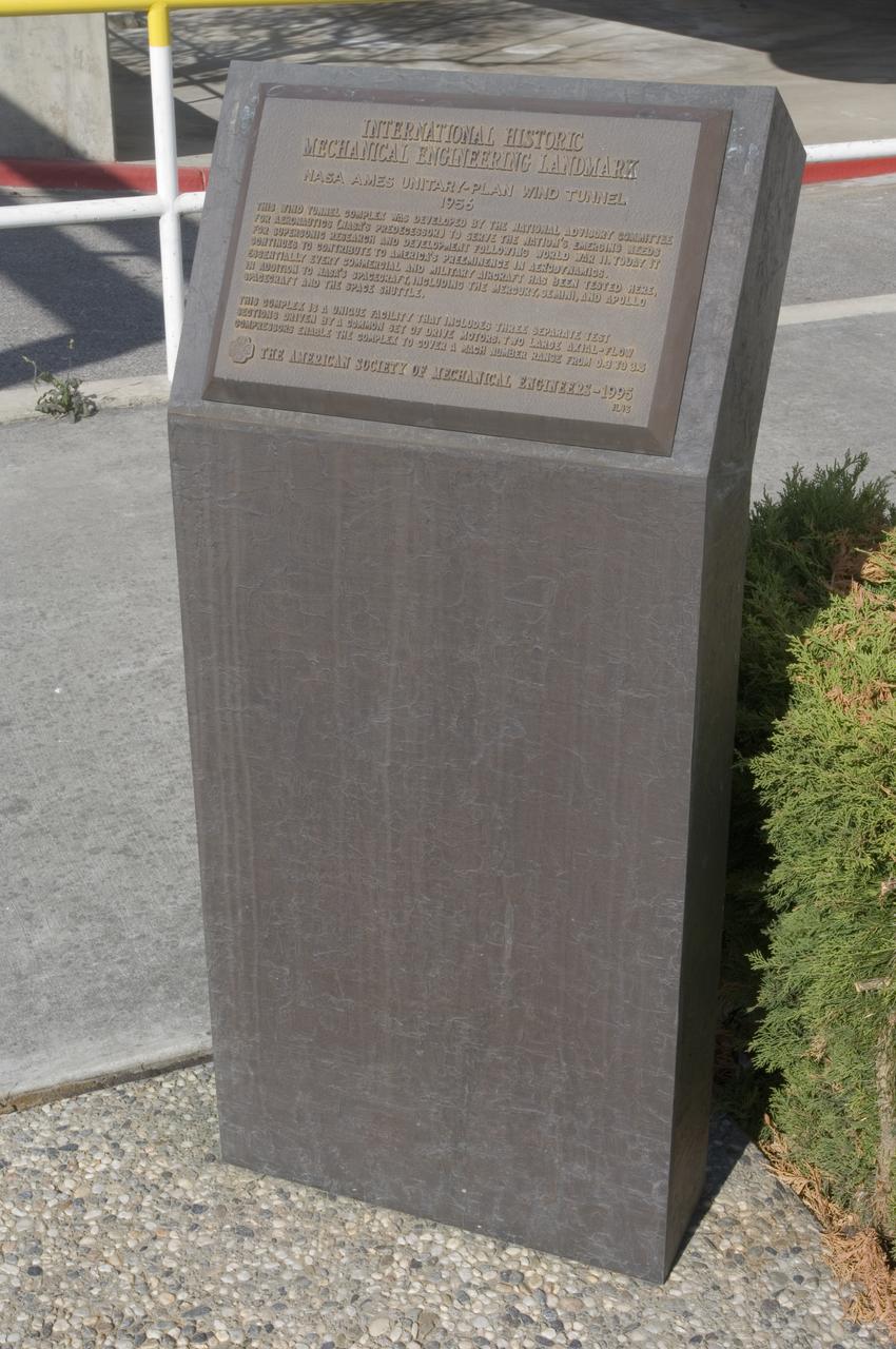
Ames and Moffett Field (MFA) historical sites and memorials Unitary Plan Wind Tunned plaza; display and historical site plaques with the NASA logo on the Wind Tunnel valve as a backdrop. shown is the Unitary International Historic Mechanical Engineering Landmark Dedication plaque (American Society of Mechanical Engineers) May 5, 1995
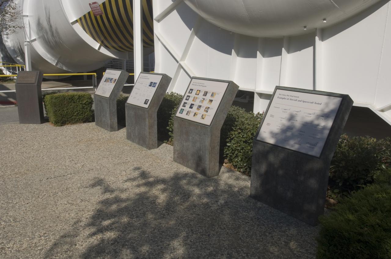
Ames and Moffett Field (MFA) historical sites and memorials Unitary Plan Wind Tunned plaza; display and historical site plaques with the NASA logo on the Wind Tunnel valve as a backdrop.
Ames and Moffett Field (MFA) historical sites and memorials Unitary Plan Wind Tunned plaza; display and historical site plaques with the NASA logo on the Wind Tunnel valve as a backdrop.
Ames and Moffett Field (MFA) historical sites and memorials Unitary Plan Wind Tunned plaza; display and historical site plaques with the NASA logo on the Wind Tunnel valve as a backdrop.
Ames and Moffett Field (MFA) historical sites and memorials Unitary Plan Wind Tunned plaza; display and historical site plaques with the NASA logo on the Wind Tunnel valve as a backdrop.

Ames and Moffett Field (MFA) historical sites and memorials Unitary Plan Wind Tunned plaza; display and historical site plaques with the NASA logo on the Wind Tunnel valve as a backdrop.
Ames and Moffett Field (MFA) historical sites and memorials Unitary Plan Wind Tunned plaza; display and historical site plaques with the NASA logo on the Wind Tunnel valve as a backdrop.
Ames and Moffett Field (MFA) historical sites and memorials Unitary Plan Wind Tunned plaza; display and historical site plaques with the NASA logo on the Wind Tunnel valve as a backdrop.

0.4 Percent Scale Space Launch System Wind Tunnel Test 0.4 Percent Scale SLS model installed in the NASA Langley Research Center Unitary Plan Wind Tunnel Test Section 1 for aerodynamic force and movement testing.
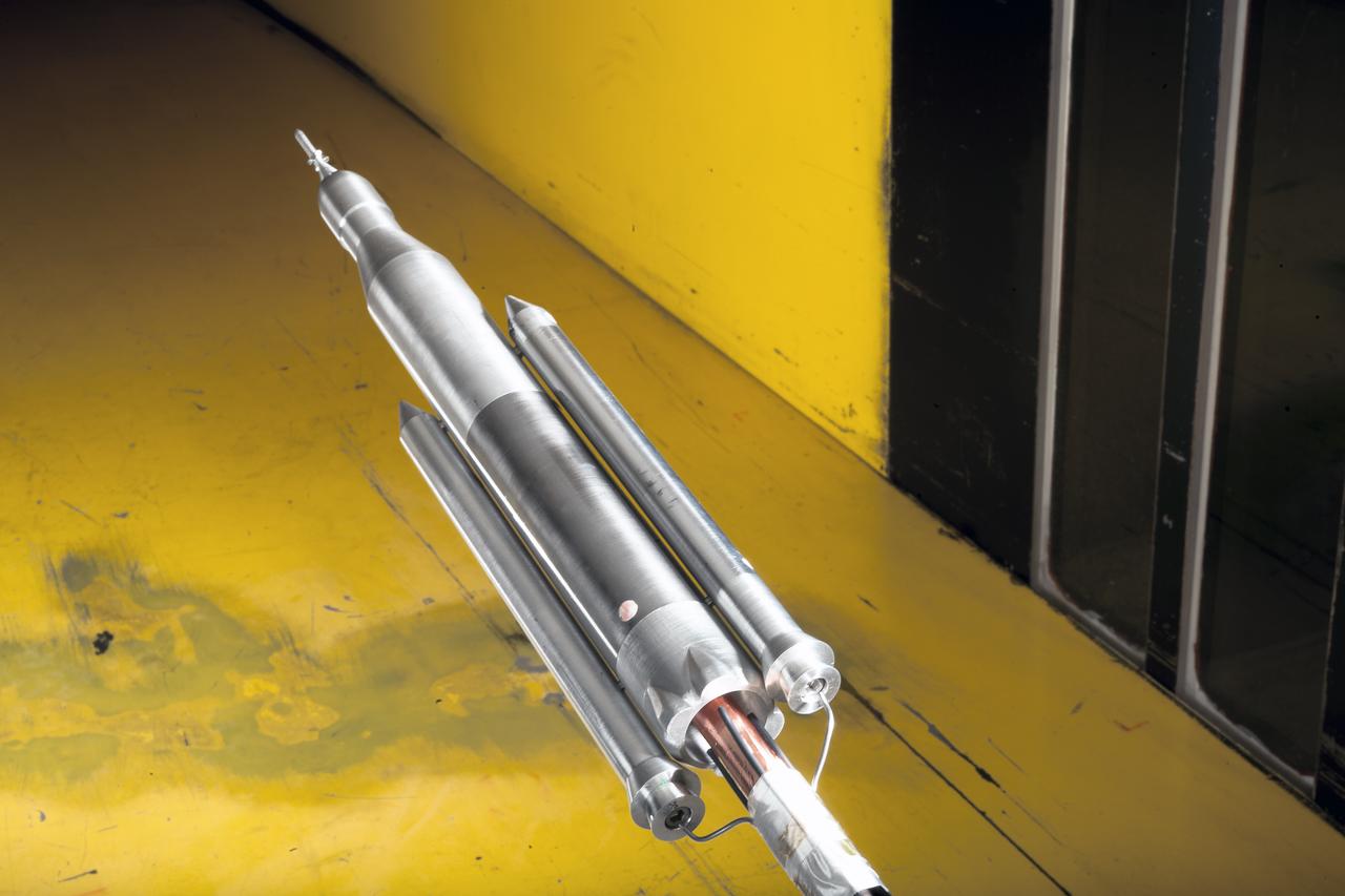
0.4 Percent Scale Space Launch System Wind Tunnel Test 0.4 Percent Scale SLS model installed in the NASA Langley Research Center Unitary Plan Wind Tunnel Test Section 1 for aerodynamic force and movement testing.
0.4 Percent Scale Space Launch System Wind Tunnel Test 0.4 Percent Scale SLS model installed in the NASA Langley Research Center Unitary Plan Wind Tunnel Test Section 1 for aerodynamic force and movement testing.
0.4 Percent Scale Space Launch System Wind Tunnel Test 0.4 Percent Scale SLS model installed in the NASA Langley Research Center Unitary Plan Wind Tunnel Test Section 1 for aerodynamic force and movement testing.
0.4 Percent Scale Space Launch System Wind Tunnel Test 0.4 Percent Scale SLS model installed in the NASA Langley Research Center Unitary Plan Wind Tunnel Test Section 1 for aerodynamic force and movement testing.
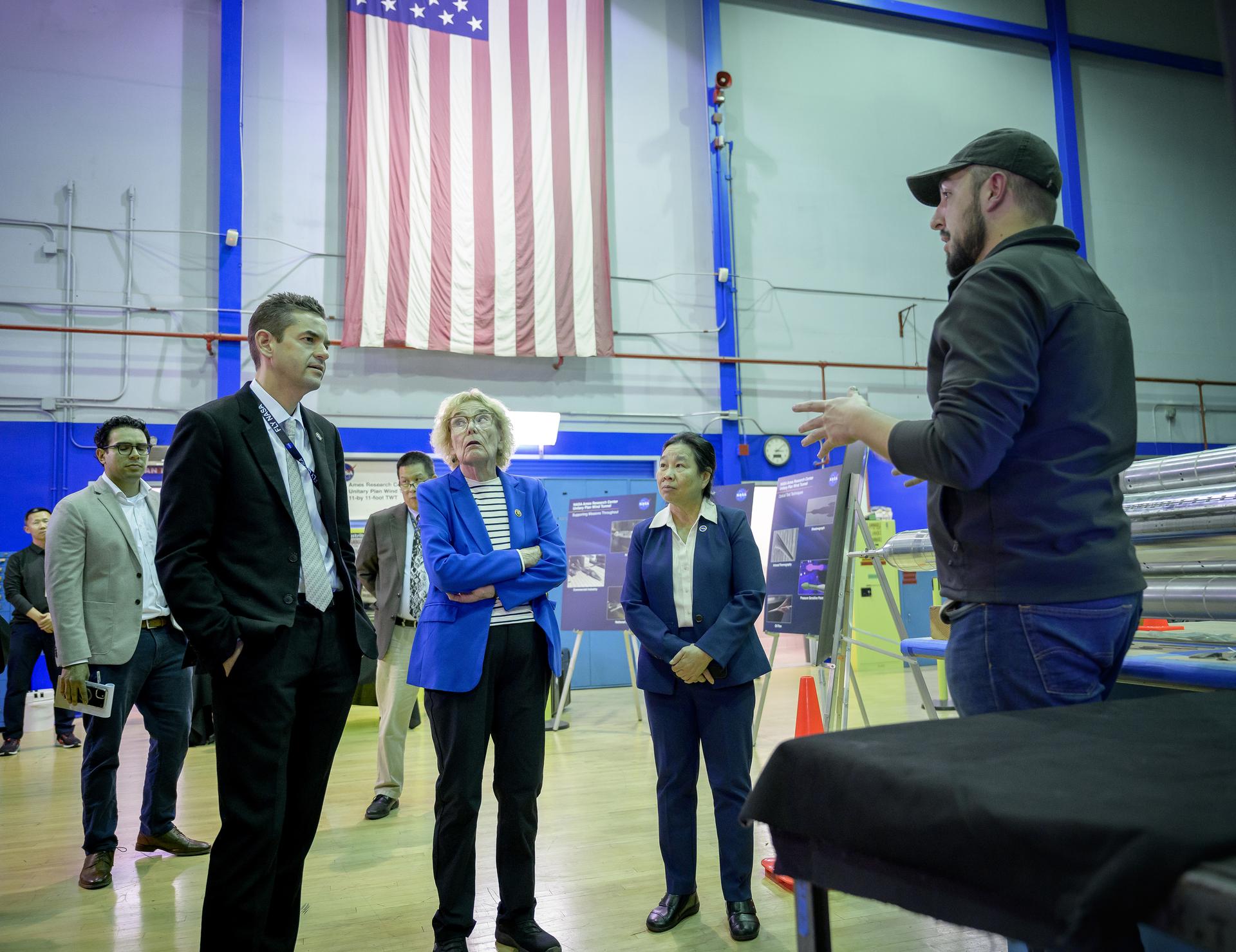
NASA Administrator Jared Isaacman, left, Congresswoman Zoe Lofgren, and Director of Aeronautics Huy Tran, right, tour the Unitary Plan Wind Tunnel (UPWT) facility in N227.
Shown is a wind tunnel test of the Ares model for force/moment testing in support of the Ares/ClV integrated vehicle at Langley Research Center, Virginia. The image is extracted from a high definition video file and is the highest resolution available.
HAMPTON, Va. – A precise scale model of the Dream Chaser spacecraft begins an evaluation inside the Unitary Plan Wind Tunnel at NASA's Langley Research Center in Virginia. The Dream Chaser is in development by Sierra Nevada Corporation in partnership with NASA's Commercial Crew Program. The data gathered from the wind tunnel was used to further test the design through the company's Commercial Crew Integrated Capability agreement with NASA. Photo credit: NASA/ David C. Bowman
Two images left out of the original order in 2011 L numbers 3800-3810 2011. UPWT Test 1998 Continuous Data Sonic Boom Test. Sonic Boom Hardware Mounted in the Langley Unitary Plan wind Tunnel(UPWT). Conical survey probes, wedge probe, and wind tunnel wall boundary layer rake. Rectangular box with wedge front end is a transducer box to that held pressure transducer for the conical probes.
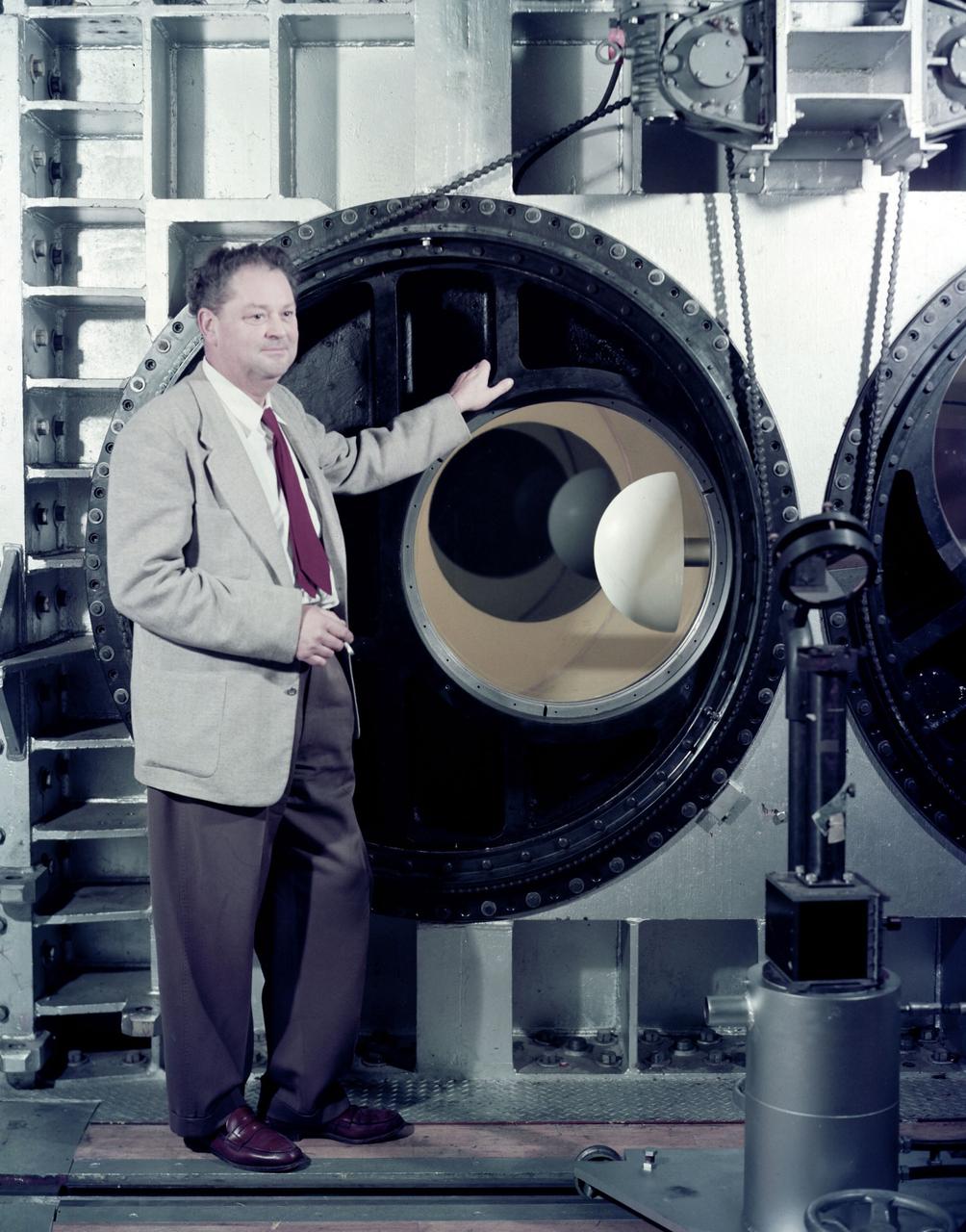
H. Julian 'Harvey' Allen in front of the NASA Ames 8_x_7 foot Supersonic Wind Tunnel test section. A blunt body model mounted in the test section is ready for testing . The 8_X_7_foot is part of the Unitary Plan WInd Tunnel Complex Note: printed in 60 year at NASA Ames Research Center by Glenn Bugos NASA SP-2000-4314
Two images left out of the original order in 2011 L numbers 3800-3810 2011. UPWT Test 1998 Continuous Data Sonic Boom Test. Sonic Boom Hardware Mounted in the Langley Unitary Plan wind Tunnel(UPWT). Conical survey probes, wedge probe, and wind tunnel wall boundary layer rake. Rectangular box with wedge front end is a transducer box to that held pressure transducer for the conical probes.
HAMPTON, Va. – NASA technician Ricky Hall works inside the Unitary Plan Wind Tunnel at NASA's Langley Research Center in Virginia to affix grains of sand to a precise scale model of the Dream Chaser spacecraft. Sierra Nevada Corporation is developing the Dream Chaser in partnership with NASA's Commercial Crew Program. The sand creates turbulence at key points to simulate the conditions the real spacecraft will encounter during its return to Earth. The data gathered from the wind tunnel was used to further test the design through the company's Commercial Crew Integrated Capability agreement with NASA. Photo credit: NASA/ David C. Bowman
HAMPTON, Va. – NASA technician Ricky Hall works inside the Unitary Plan Wind Tunnel at NASA's Langley Research Center in Virginia to affix grains of sand to a precise scale model of the Dream Chaser spacecraft. Sierra Nevada Corporation is developing the Dream Chaser in partnership with NASA's Commercial Crew Program. The sand creates turbulence at key points to simulate the conditions the real spacecraft will encounter during its return to Earth. The data gathered from the wind tunnel was used to further test the design through the company's Commercial Crew Integrated Capability agreement with NASA. Photo credit: NASA/ David C. Bowman
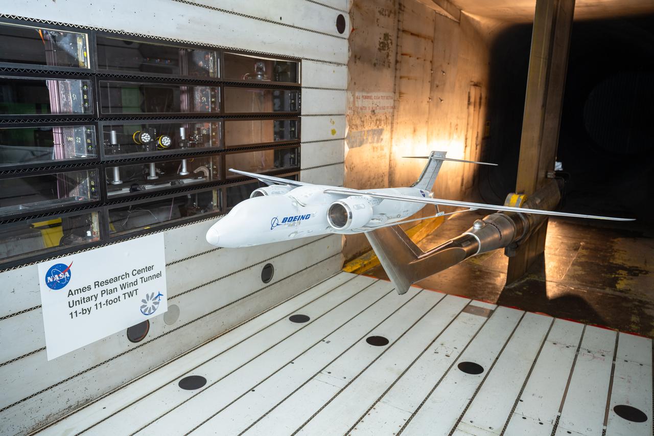
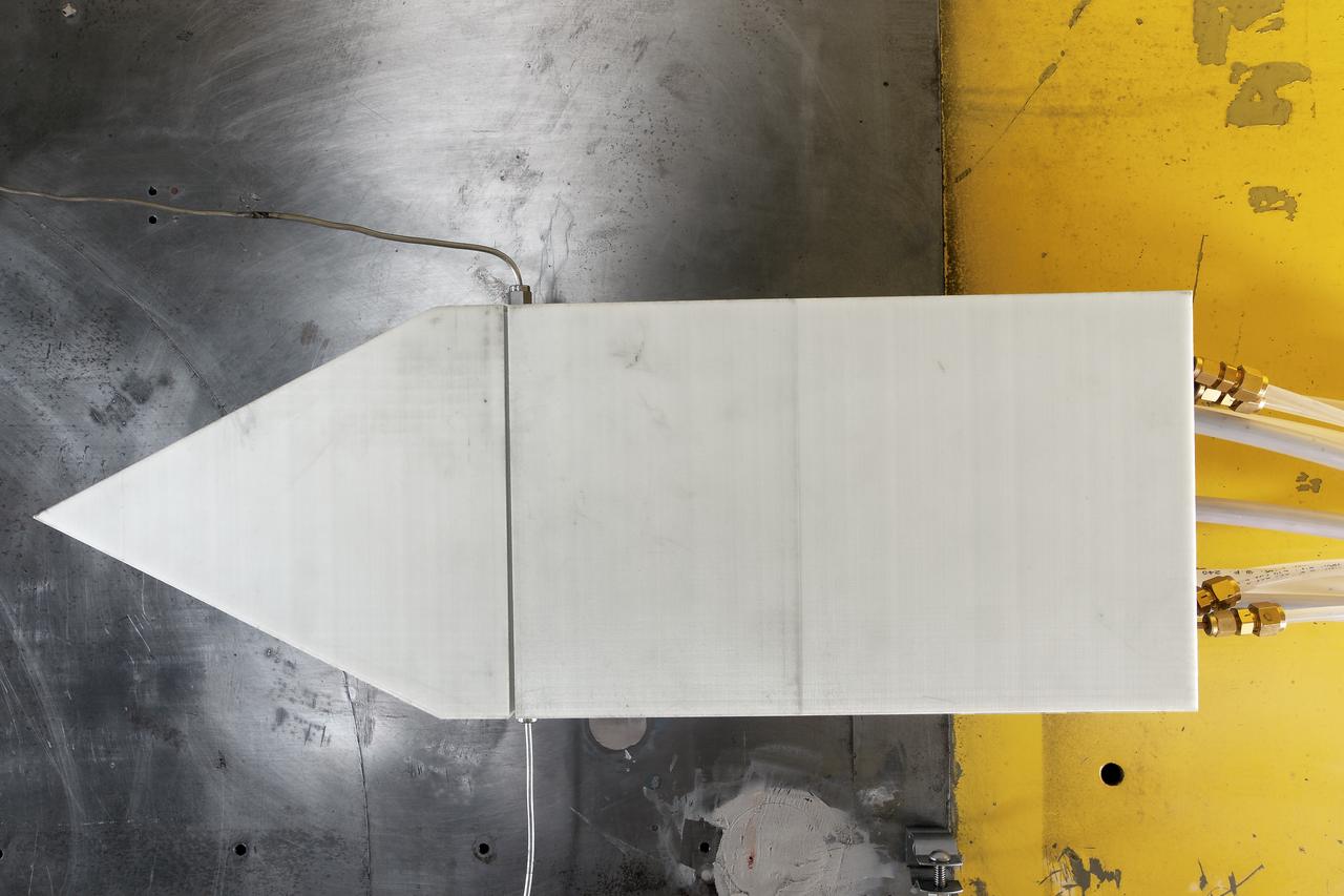
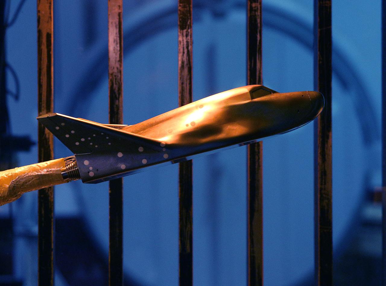
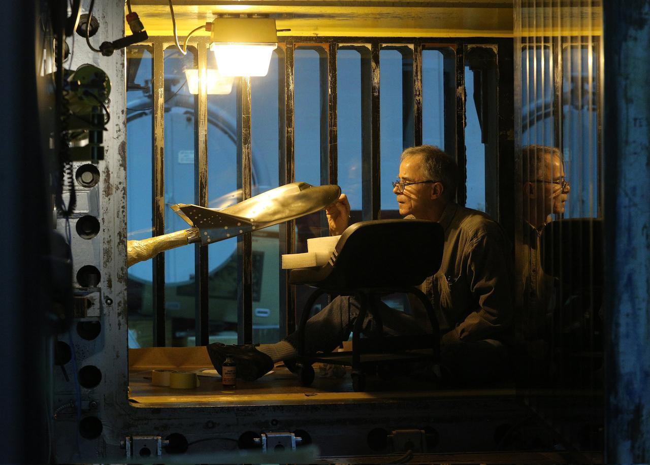
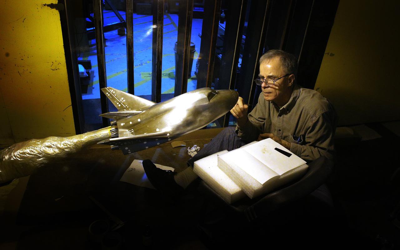
NASA’s Sustainable Flight Demonstrator project completed wind tunnel tests on a Boeing-built X-66 full-span model during a 13-week campaign between January and March 2025. The tests were completed in the 11-Foot Transonic Unitary Plan Facility at NASA’s Ames Research Center in California’s Silicon Valley. The model underwent tests in expected flight conditions to obtain engineering data to help improve the aircraft’s design and flight simulators.
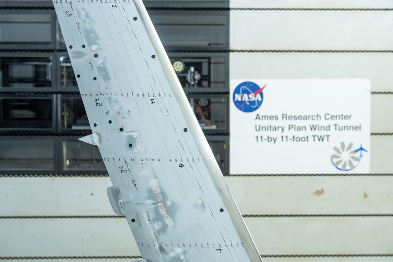
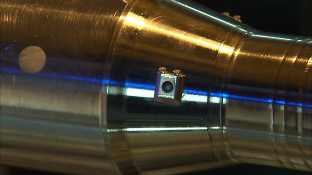
NASA’s Sustainable Flight Demonstrator project concluded wind tunnel testing in the fall of 2024. Tests on a Boeing-built X-66 model were completed at NASA’s Ames Research Center in Silicon Valley, California, in the 11-Foot Transonic Unitary Plan Facility. Pressure points, which are drilled holes with data sensors attached, are installed along the edge of the wing and allow engineers to understand the characteristics of airflow and will influence the final design of the wing.
NASA’s Sustainable Flight Demonstrator project concluded wind tunnel testing in the fall of 2024. Tests on a Boeing-built X-66 model were completed at NASA’s Ames Research Center in California’s Silicon Valley in the 11-Foot Transonic Unitary Plan Facility. The model underwent tests representing expected flight conditions to obtain engineering information to influence design of the wing and provide data for flight simulators.
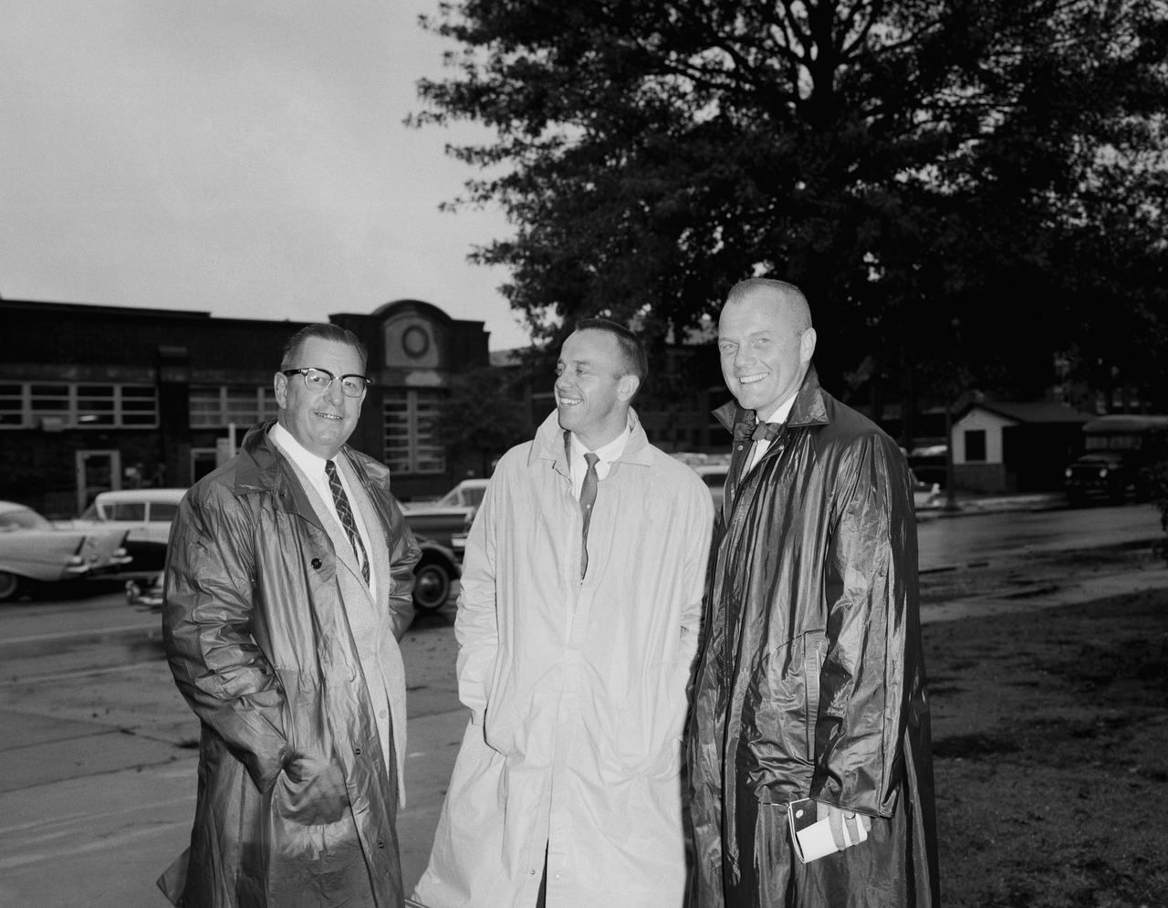
Astronauts at 1959 Langley Inspection. Astronauts at 1959 Langley Inspection: The seven are shown in the Unitary Plan Wind Tunnel NASA Langley. The astronauts left to right: John H. Glenn Jr., M.Scot Carpenter, Virgil I.Grissom, Walter M. Schirra Jr., L. Gordon Cooper, Alan B. Shepard Jr.and Donald K. Slayton.
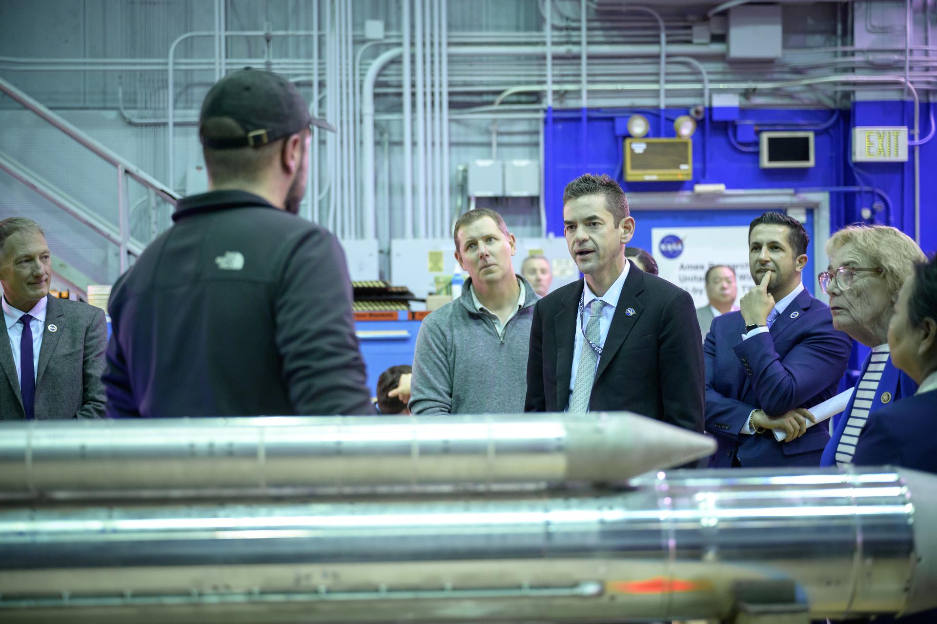
NASA Administrator Jared Isaacman, center, speaks to wind tunnel staff, with Associate Center Director Amir Deylami, back, and Congresswoman Zoe Lofgren, right,
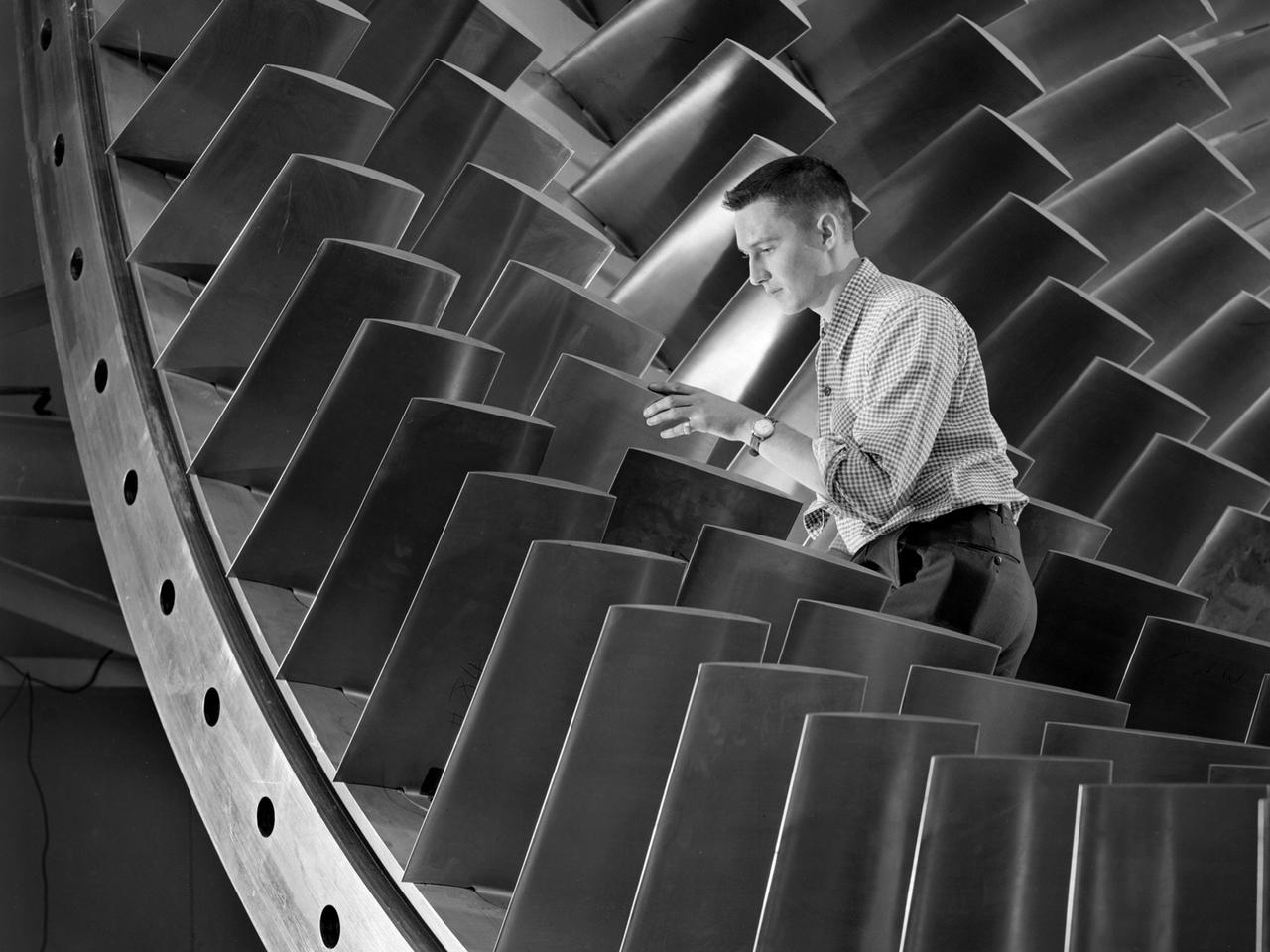
An engineer examines the main compressor for the 10- by 10-Foot Supersonic Wind Tunnel at the National Advisory Committee for Aeronautics (NACA) Lewis Flight Propulsion Laboratory. The engineers were preparing the new wind tunnel for its initial runs in early 1956. The 10- by 10 was the most powerful propulsion wind tunnel in the nation. The facility was part of Congress’ Unitary Plan Act which coordinated wind tunnel construction at the NACA, Air Force, industry, and universities. The 10- by 10 was the largest of the three NACA tunnels built under the act. The 20-foot diameter eight-stage axial flow compressor, seen in this photograph, could generate air flows up to Mach 2.5 through the test section. The stainless steel compressor had 584 blades ranging from 1.8 to 3.25 feet in length. This main compressor was complemented by a secondary axial flow compressor. Working in tandem the two could generate wind streams up to Mach 3.5. The Cleveland Chamber of Commerce presented NACA Lewis photographer Bill Bowles with a second place award for this photograph in their Business and Professional category. The photograph was published in October 1955 edition of its periodical, The Clevelander, which highlighted local professional photographers. Fellow Lewis photographer Gene Giczy won second place in another category for a photograph of Cleveland Municipal Airport.
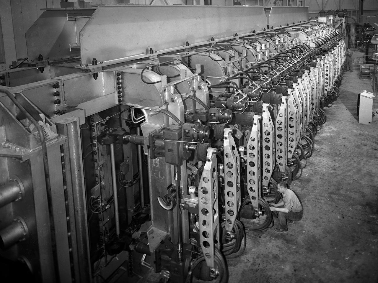
A mechanic checks the tubing on one of the many jacks which control the nozzle section of the 10- by 10-Foot Supersonic Wind Tunnel at the National Advisory Committee for Aeronautics (NACA) Lewis Flight Propulsion Laboratory. The 10- by 10-foot tunnel, which had its official opening in May 1956, was built under the Congressional Unitary Plan Act which coordinated wind tunnel construction at the NACA, Air Force, industry, and universities. The 10- by 10 was the largest of the three NACA tunnels built under the act. The 10- by 10 wind tunnel can be operated as a closed circuit for aerodynamic tests or as an open circuit for propulsion investigations. The 10-foot tall and 76-foot long stainless steel nozzle section just upstream from the test section can be adjusted to change the speed and composition of the air flow. Hydraulic jacks, seen in this photograph, flex the 1.37-inch thick walls of the tunnel nozzle. The size of the nozzle’s opening controls the velocity of the air through the test section. Seven General Electric motors capable of generating 25,000 horsepower produce the Mach 2.5 and 2.5 airflows. The facility was mostly operated at night due to its large power load requirements.
The 10- by 10-Foot Supersonic Wind Tunnel at the NACA Lewis Flight Propulsion Laboratory was built under the Congressional Unitary Plan Act which coordinated wind tunnel construction at the NACA, Air Force, industry, and universities. The 10- by 10, which began operation in 1956, was the largest of the three NACA tunnels built under the act. Researchers could test engines up to five feet in diameter in the 10- by 10-foot test section. A 250,000-horsepower axial-flow compressor fan can generate airflows up to Mach 3.5 through the test section. The incoming air must be dehumidified and cooled so that the proper conditions are present for the test. A large air dryer with 1,890 tons of activated alumina soaks up 1.5 tons of water per minute from the airflow. A cooling apparatus equivalent to 250,000 household air conditioners is used to cool the air. The air heater is located just upstream from the test section. Natural gas is combusted in the tunnel to increase the air temperature. The system could only be employed when the tunnel was run in its closed-circuit propulsion mode.
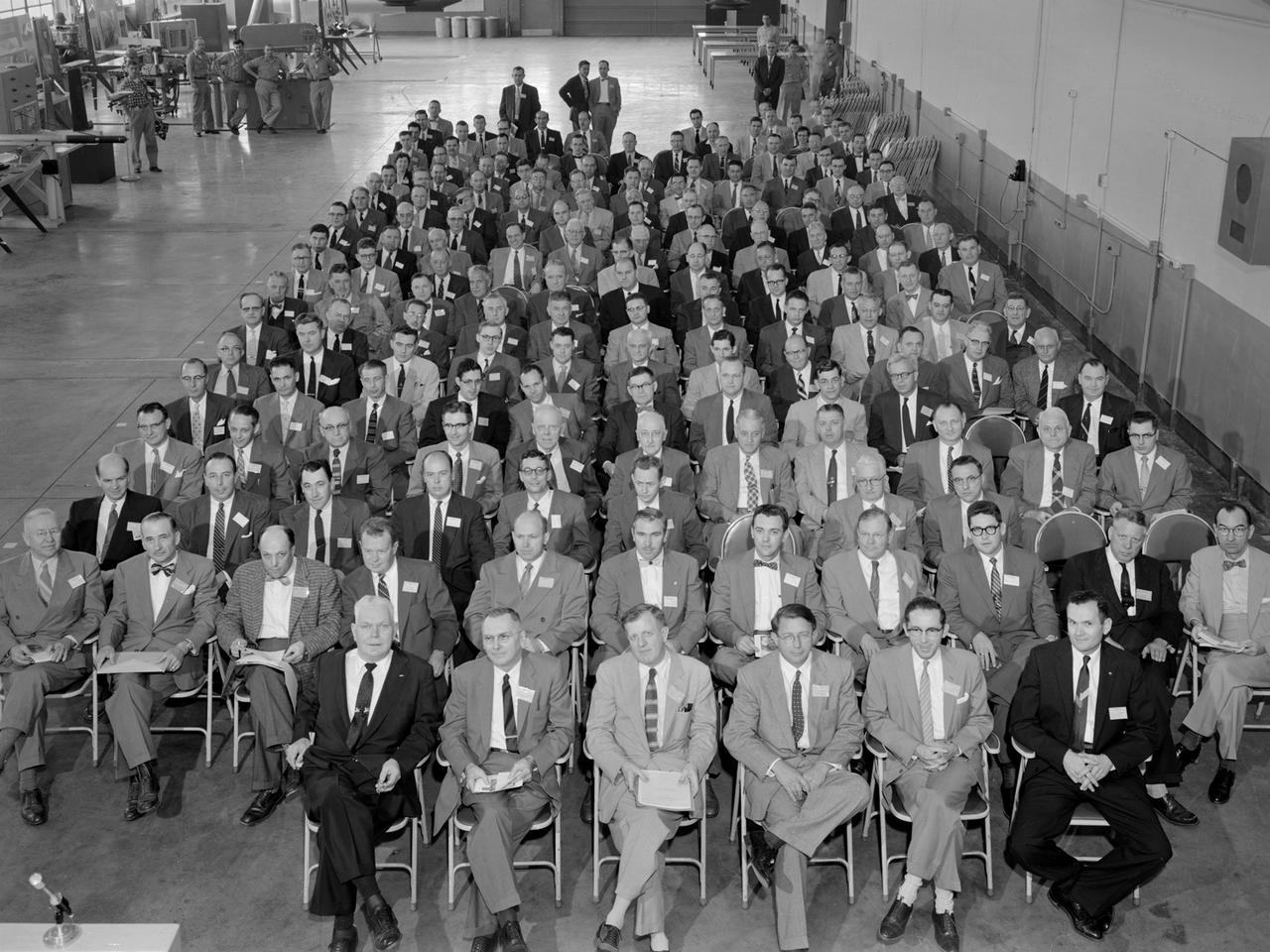
Attendees listen during the May 22, 1956 Inspection of the new 10- by 10-Foot Supersonic Wind Tunnel at the National Advisory Committee for Aeronautics (NACA) Lewis Flight Propulsion Laboratory. The facility, known at the time as the Lewis Unitary Plan Tunnel, was in its initial stages of operation. The $33 million 10- by 10 was the most powerful wind tunnel in the nation. Over 150 guests from industry, other NACA laboratories, and the media attended the event. The speakers, from left to right in the front row, addressed the crowd before the tour. Lewis Director Raymond Sharp began the event by welcoming the visitors to the laboratory. NACA Director Hugh Dryden discussed Congress’ Unitary Plan Act and its effect on the creation of the facility. Lewis Associate Director Abe Silverstein discussed the need for research tools and the 10- by 10’s place among the NACA’s other research facilities. Lewis Assistant Director Eugene Wasielewski described the detailed design work that went into the facility. Carl Schueller, Chief of the 10- by 10, described the tunnel’s components and how the facility operated. Robert Godman led the tour afterwards. The 10- by 10 can test engines up to five feet in diameter at supersonic speeds and simulated altitudes of 30 miles. Its main purpose is to investigate problems relating to engine inlet and outlet geometry, engine matching and interference effects, and overall drag. The tunnel’s 250,000-horsepower electric motor drive, the most powerful of its kind in the world, creates air speeds between Mach 2.0 and 3.5.
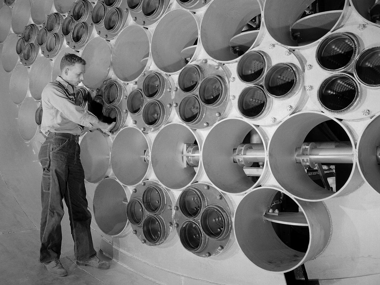
A 24-foot diameter swing valve is seen in an open position inside the new 10- by 10-Foot Supersonic Wind Tunnel at the National Advisory Committee for Aeronautics (NACA) Lewis Flight Propulsion Laboratory. The 10- by 10 was the most powerful propulsion wind tunnel in the nation. After over three years of construction the tunnel was ready to conduct its first tests in early 1956. The 10- by 10-foot tunnel was part of Congress’ Unitary Plan Act which coordinated wind tunnel construction at the NACA, Air Force, industry, and universities. The 10- by 10 was the largest of the three NACA tunnels built under the act. This large swinging valve is critical to the operation of the facility. In one position the valve seals off the tunnel exhaust, making the tunnel a closed circuit, which is used for aerodynamic testing of models. In its other position, the valve acts as a seal across the tunnel and leaves the tunnel exhaust open. This arrangement is used when engines are fired. The air going through the tunnel is taken from the atmosphere and returned to the atmosphere after one pass through the tunnel. Engines up to five feet in diameter can be tested in the 10- by 10-foot test section. Air flows up to Mach 3.5 can be fed through the test section by a 250,000-horsepower axial-flow compressor fan. The incoming air must be dehumidified and cooled so that the proper conditions are present for the test. A large air dryer with 1,890 tons of activated alumina soaks up 1.5 tons of water per minute from the air flow. A cooling apparatus equivalent to 250,000 household air conditioners is used to cool the air.
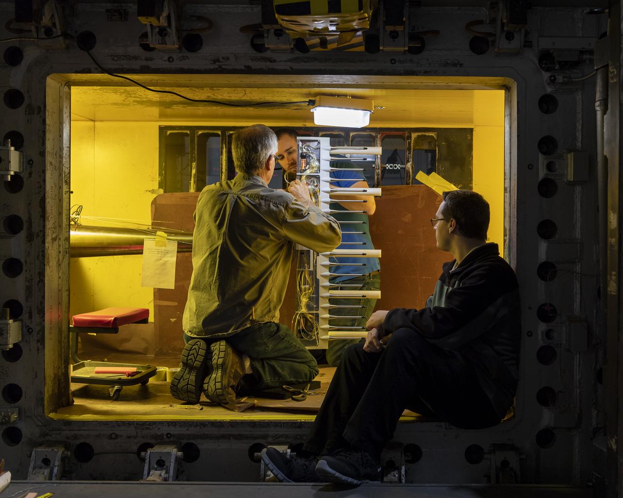
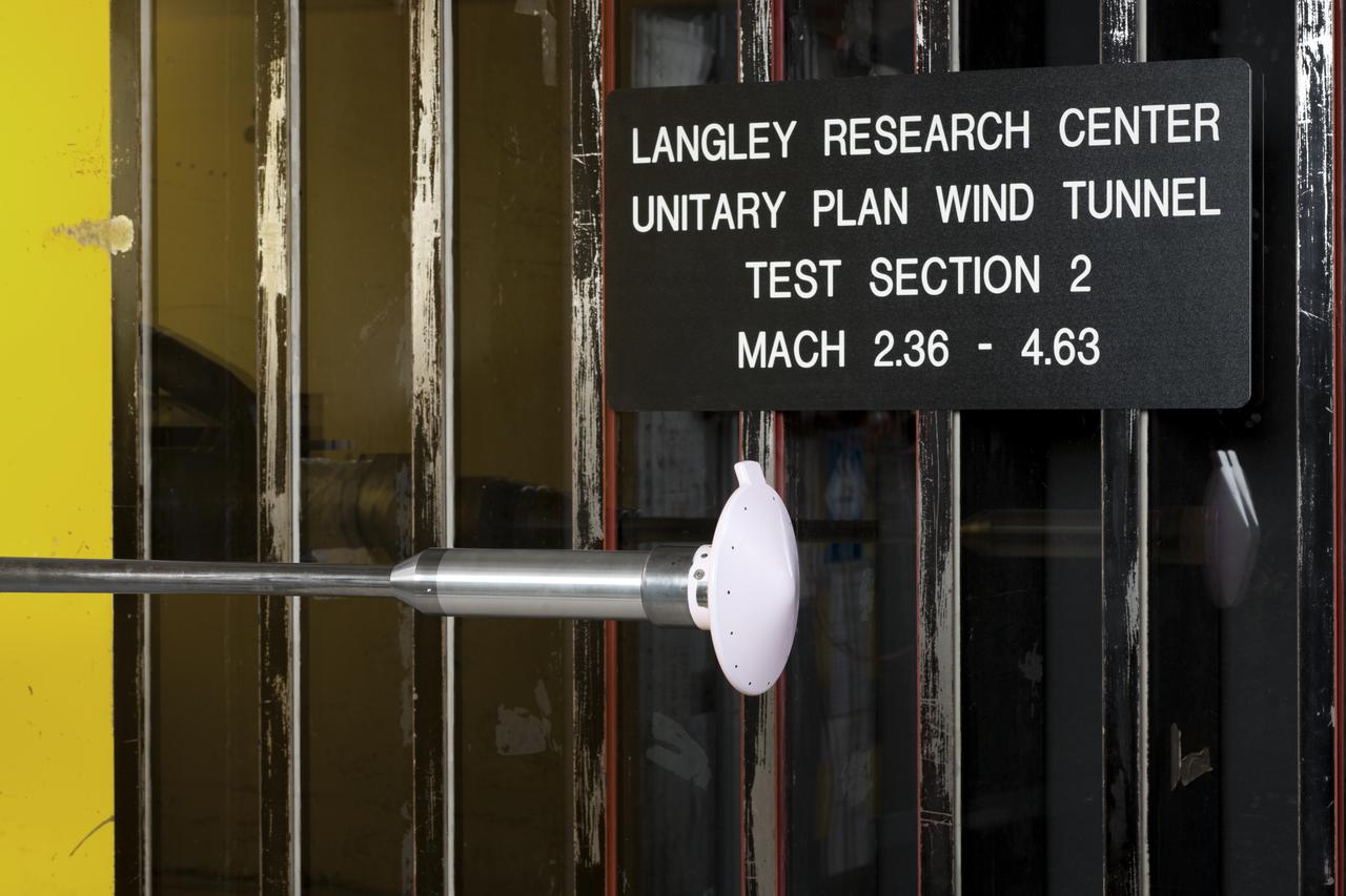
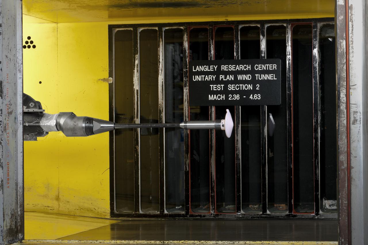
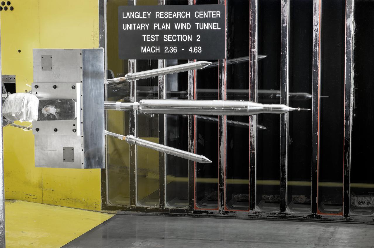
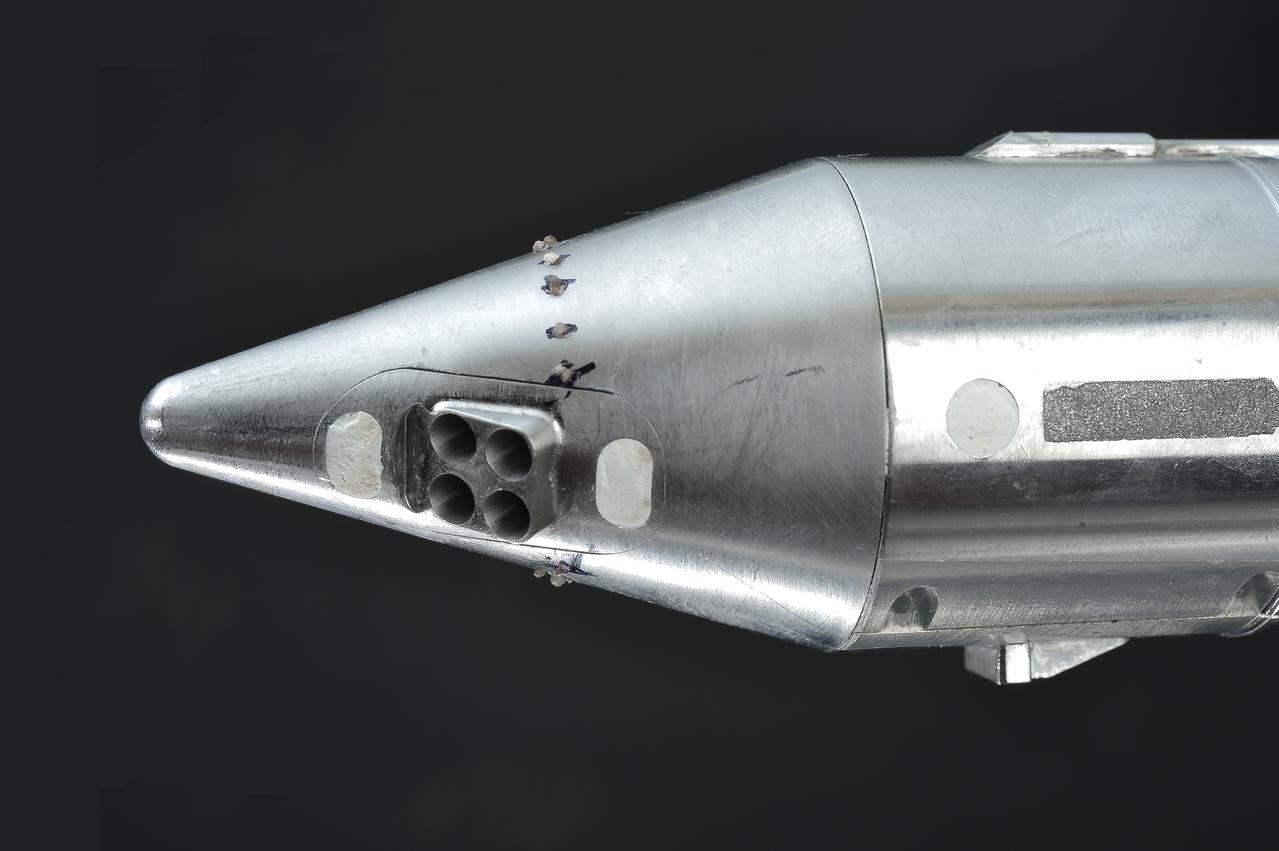
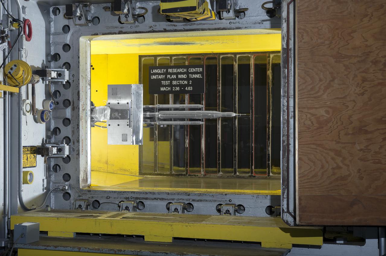
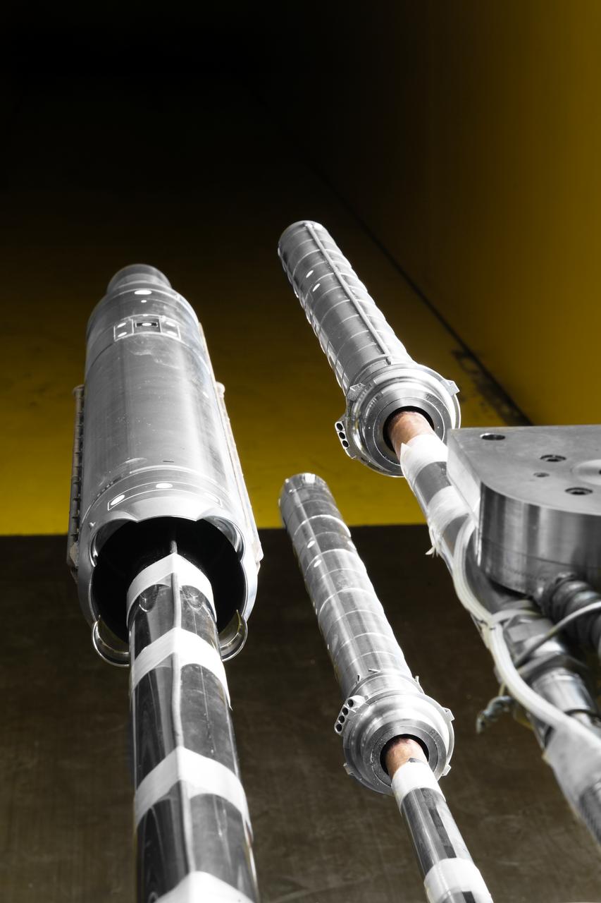
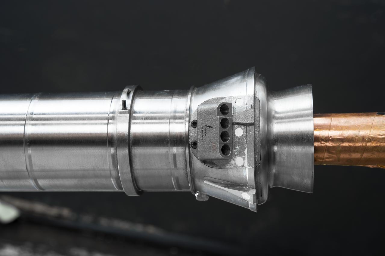
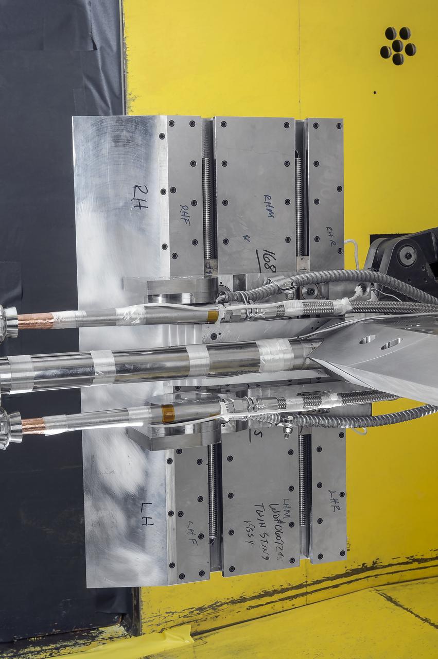
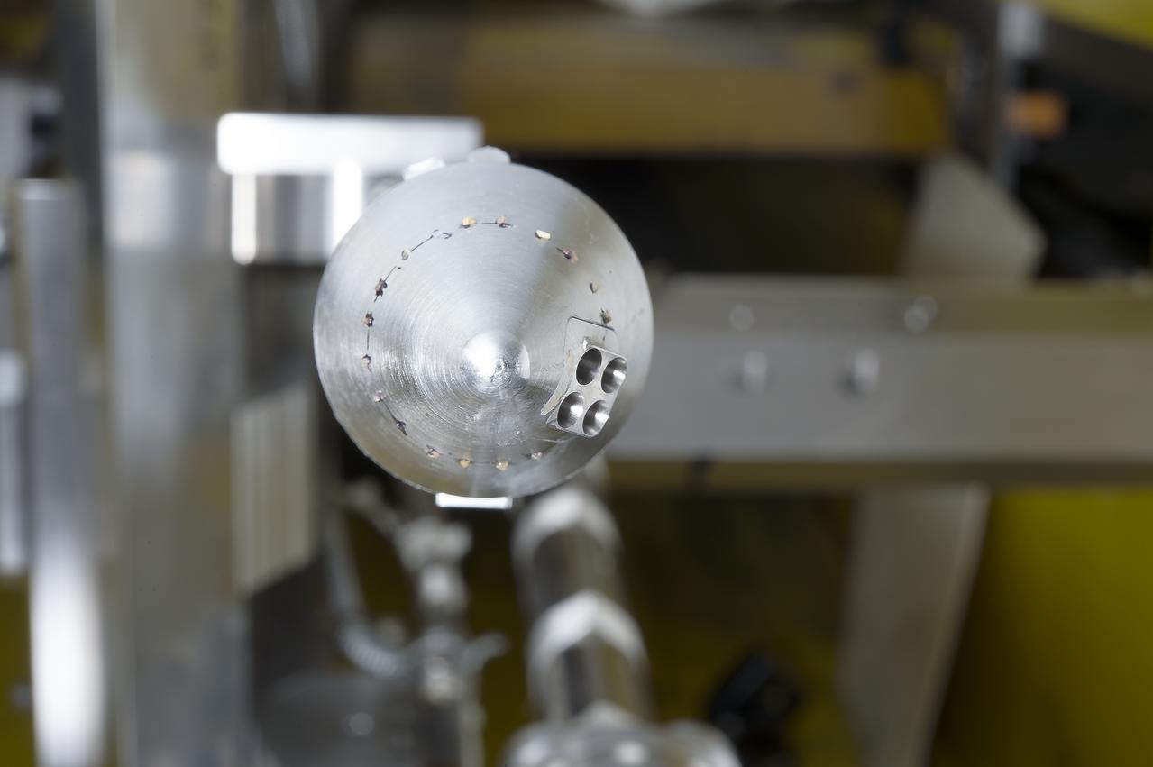
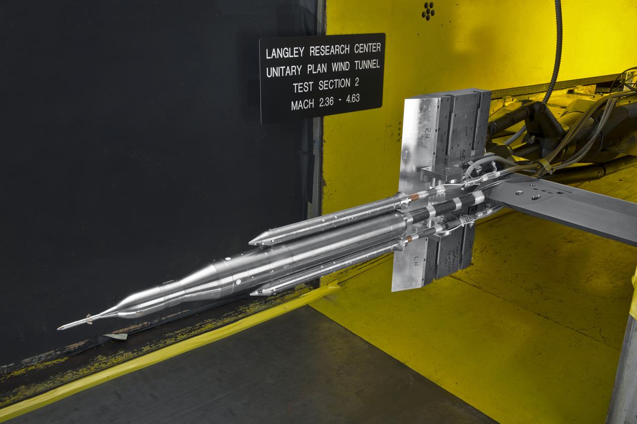
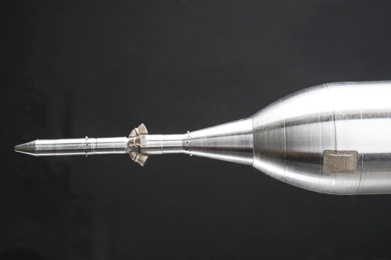
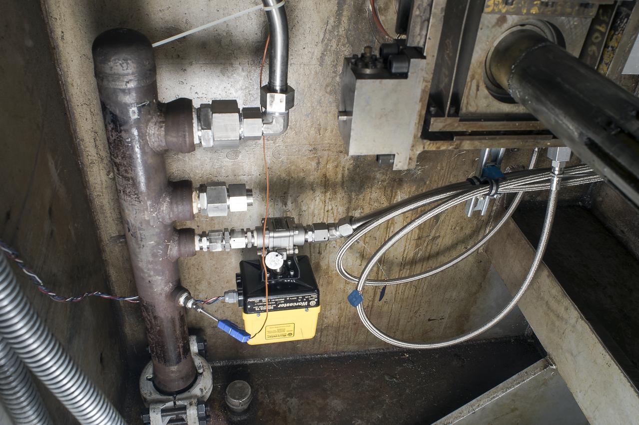
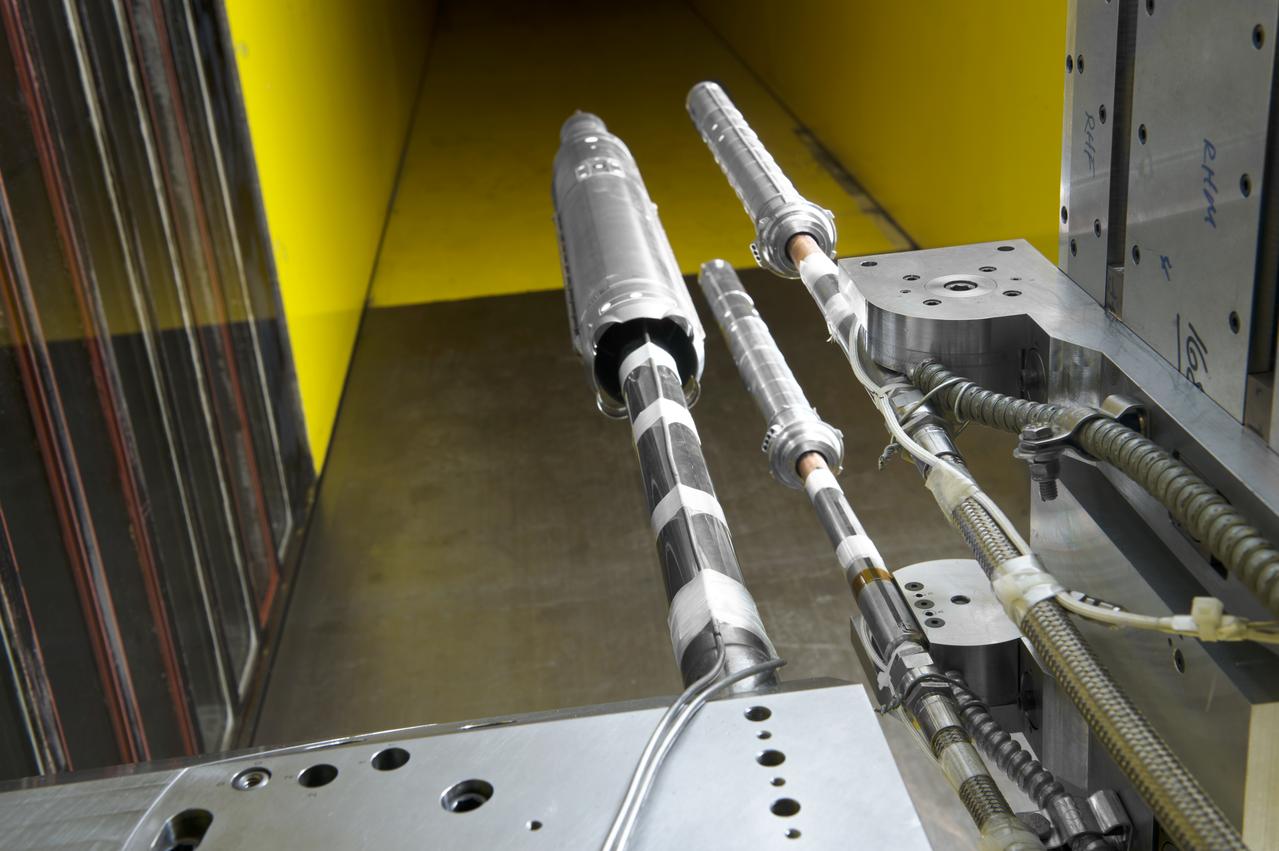
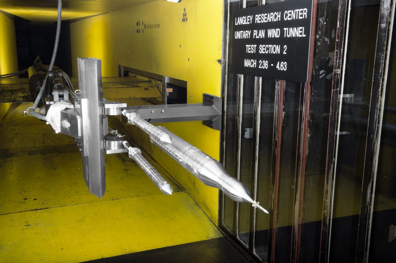
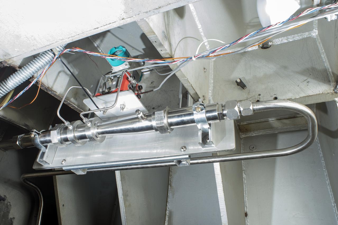
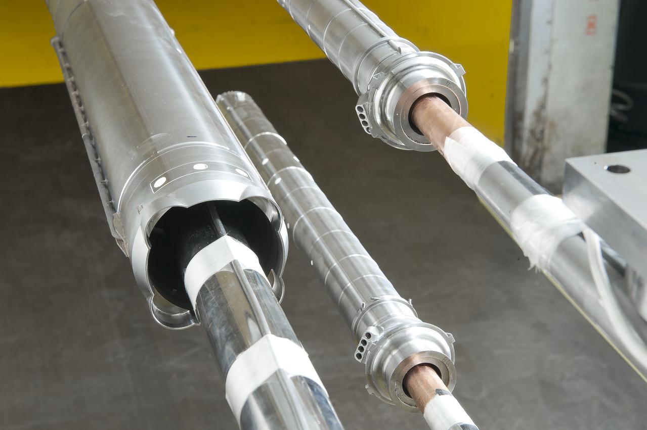
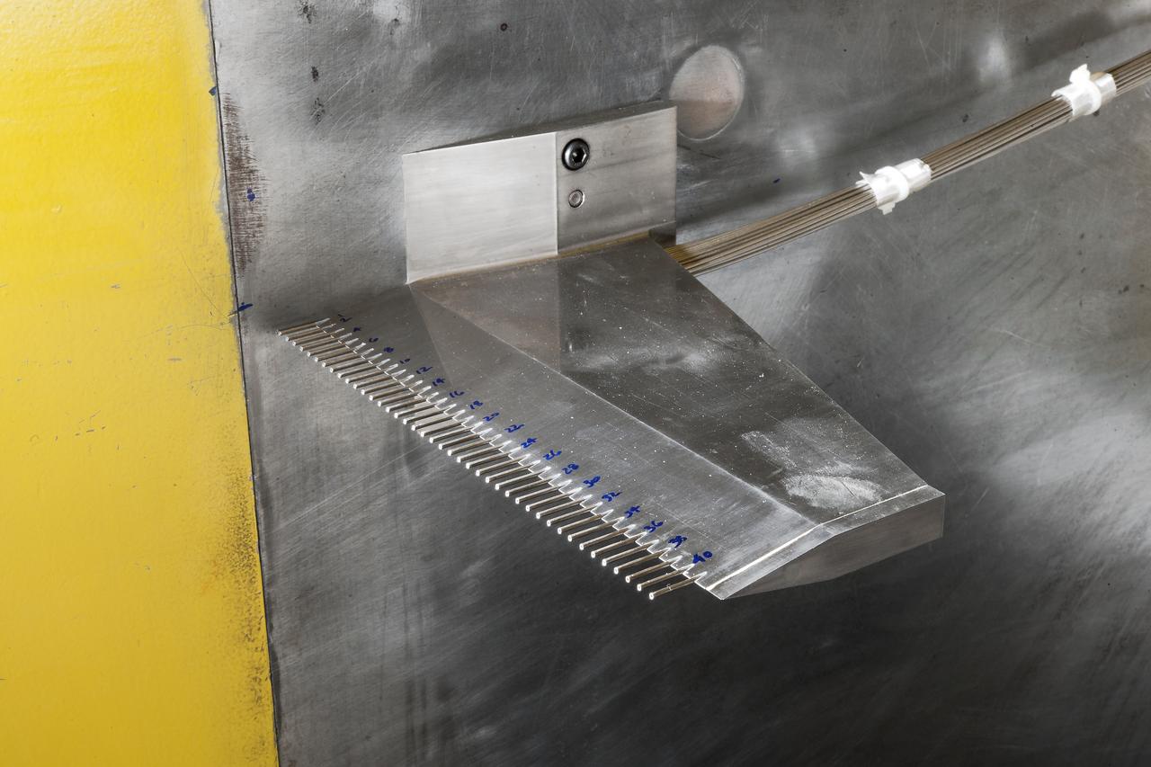
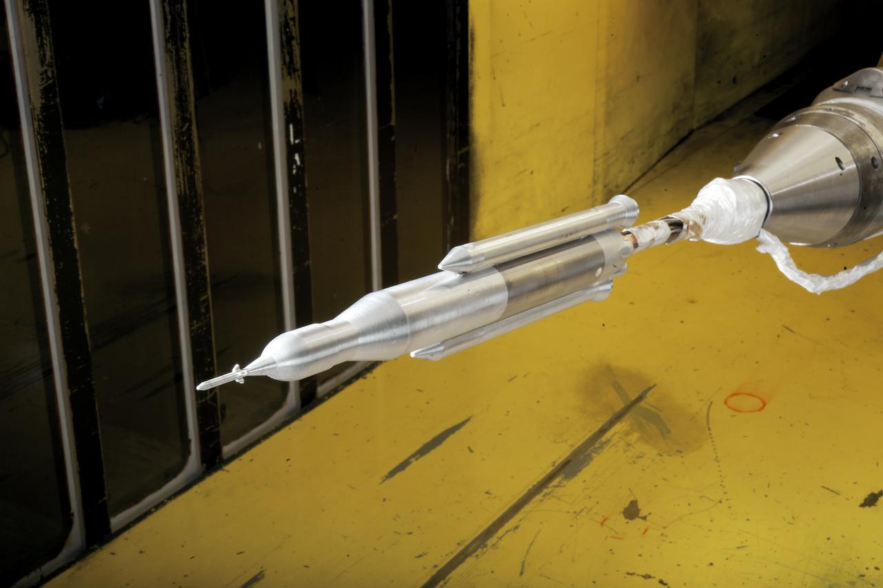
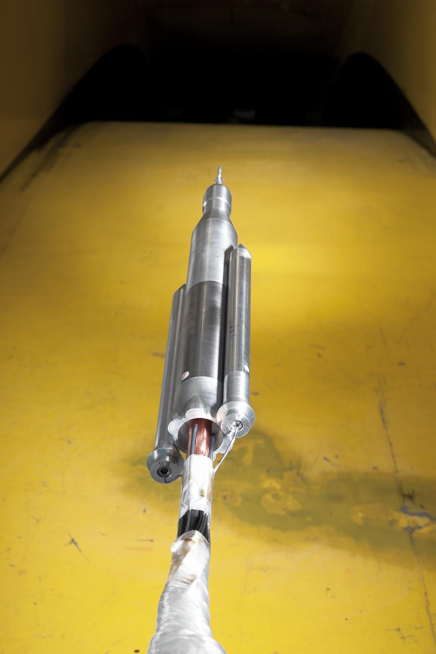
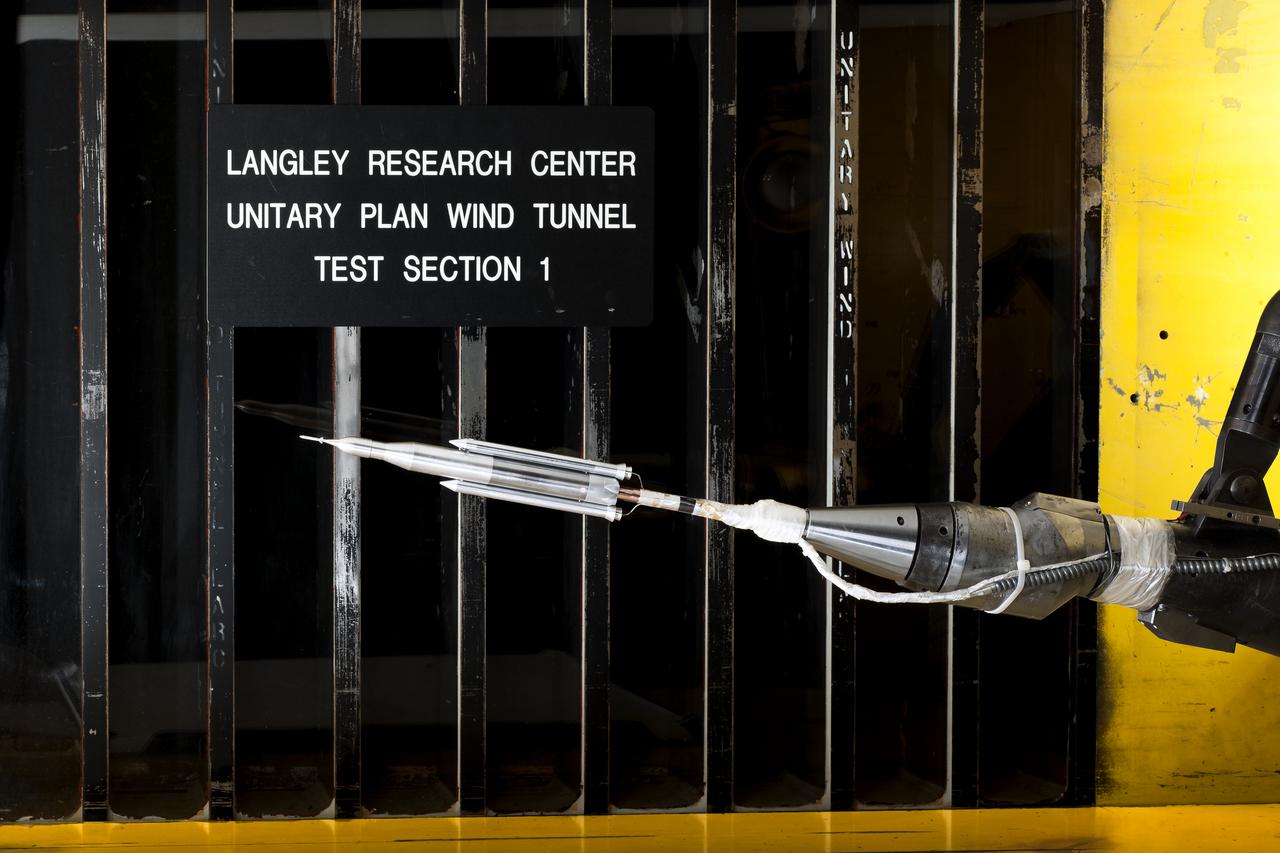
LaRC OCIO's Media Solutions Branch Photographer Harlen Capen photographed the installation of a new flow survey rake for the supersonic Unitary Plan Wind Tunnel (UPWT). The hardware – shown installed in the 4-foot, high-Mach-number Test Section 2 with a coating of Pressure Sensitive Paint – consists of a purpose-built sting, rake body, and two different types of pressure measurement probes. The survey rake will be used to characterize the flow in the test section in support of the "CFD Central Flight Dynamics as a Surrogate for High Speed Supersonic Tests" People in the photo L to R are, Ricky L. Hall, Jacobs Technology, Inc.,Supersonic/Hypersonic Testing Branch - Group A, Alexander (Alex) Moore Jacobs Technology, Inc, Supersonic/Hypersonic Testing Branch and Mathew A. (Alec) Reed, Jacobs Technology, In. NASA photographer Harlen Capen won First Place in the NASA's 2019 Still Photographer of the Year competition in the "People" category with this image.