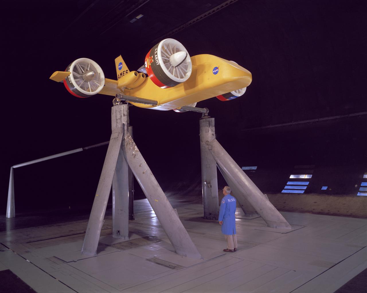
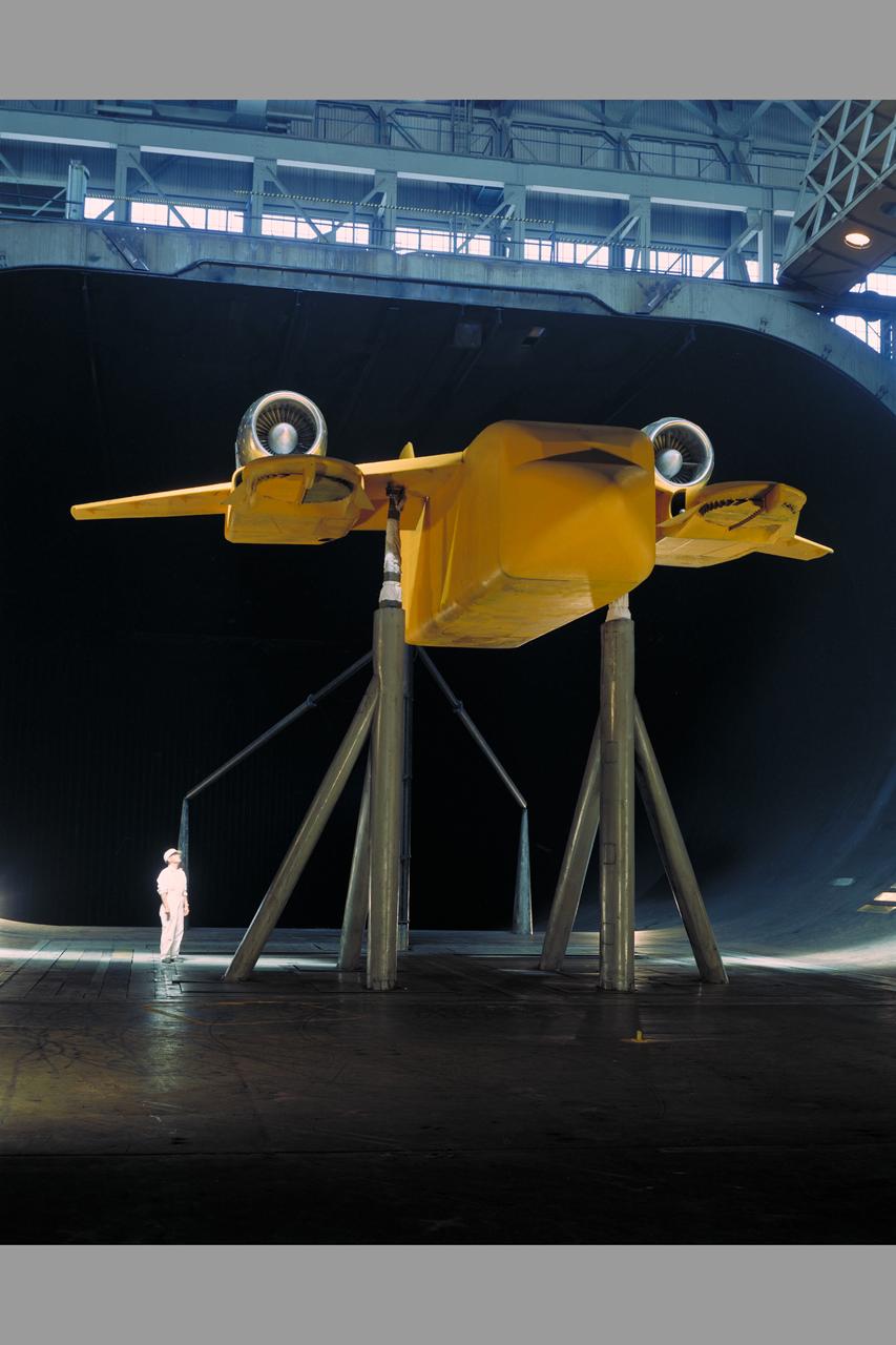
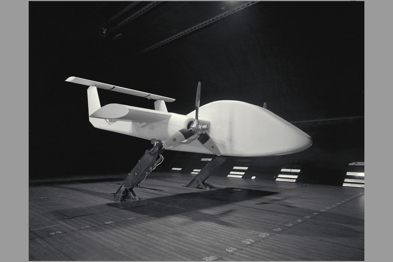
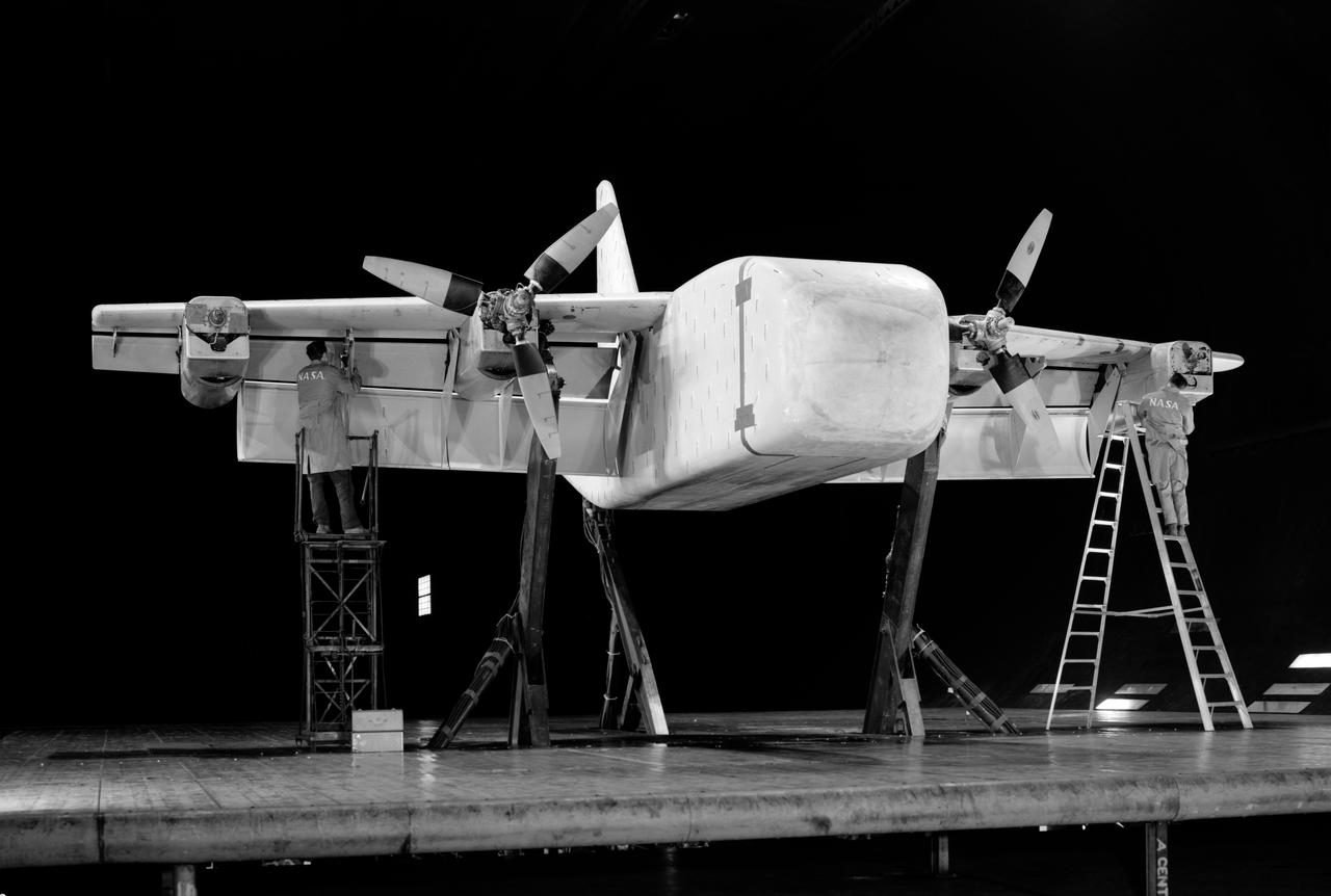
3/4 front view from below, showing Pods and Fan Rotating. March A. Zeiger standing in front. Tandem Dual Ducted Fan V/STOL Model in Ames 40x80 foot Wind Tunnel
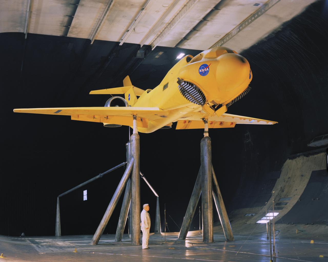
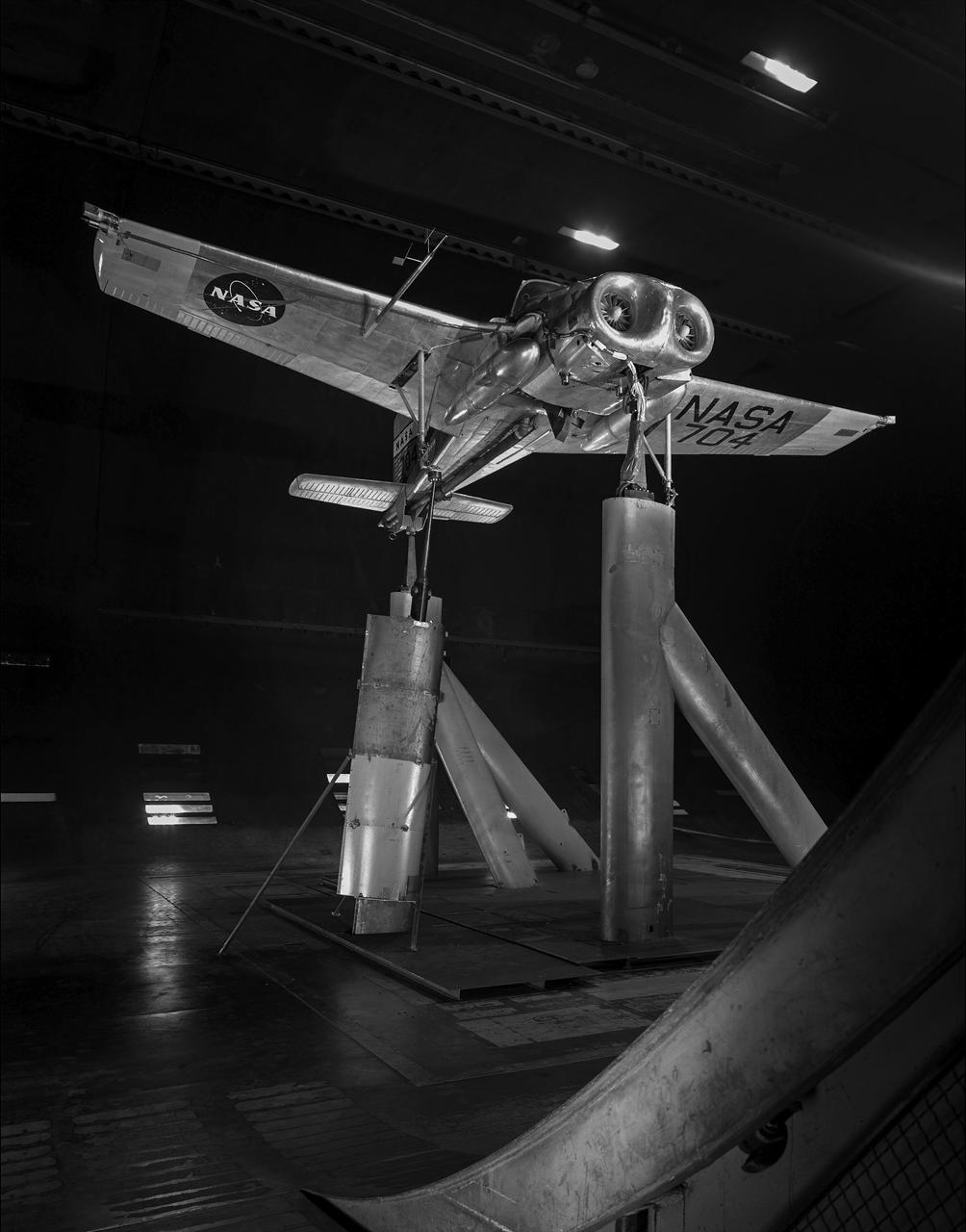
3/4 front view of McDonnell-Douglas Large-Scale lift fan, vertical and/or short take-off and landing (V/STOL), transport model. Francis Malerick in photograph. The McDonnell Douglas DC-9 (initially known as the Douglas DC-9) is a twin-engine, single-aisle jet airliner.
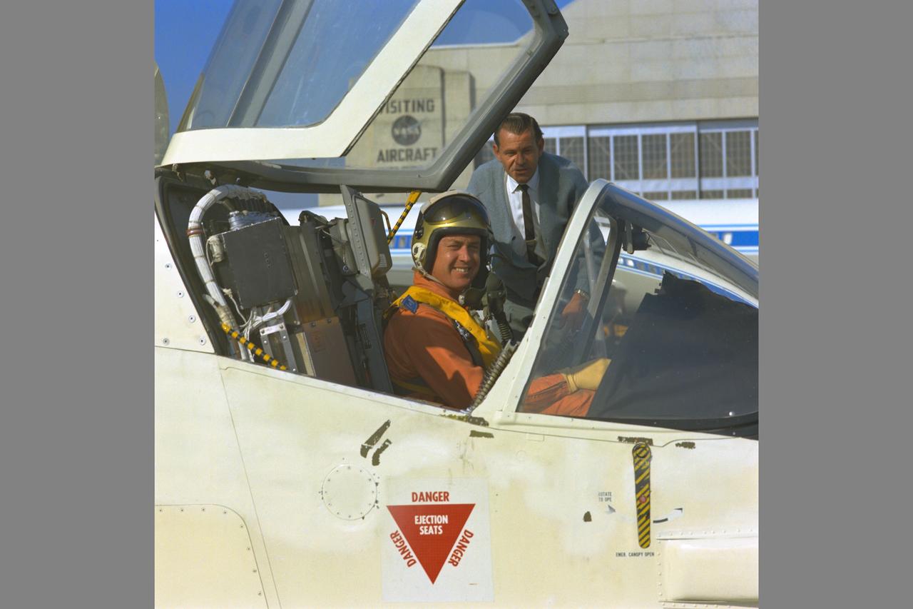
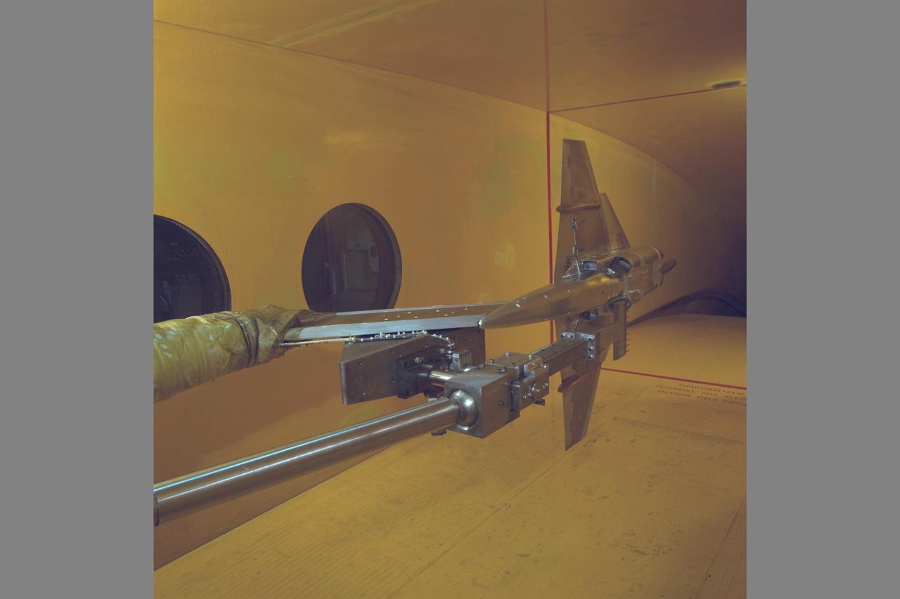
Ryan XV-5B V/STOL aircraft with pilot
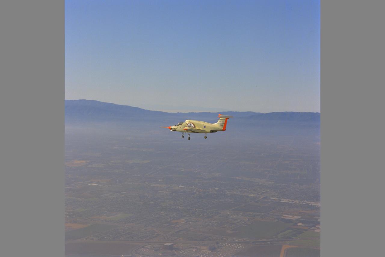
Ryan XV-5B V/STOL aircraft
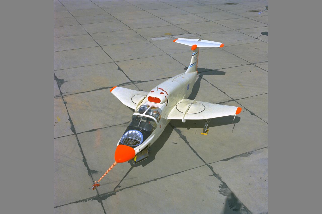
NASA Photographe Ryan XV-5B V/STOL aircraft
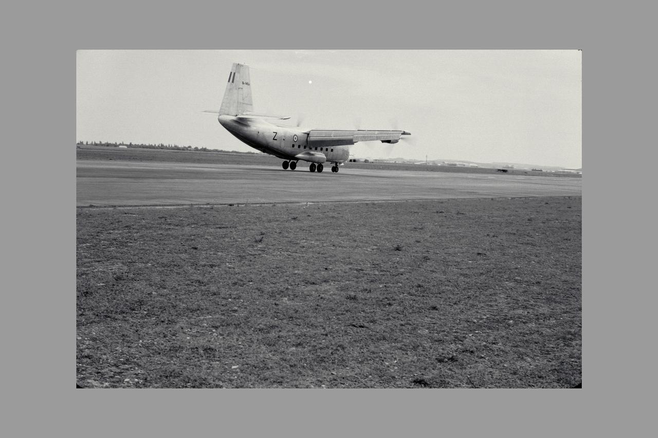
3/4 REAR VIEW OF Breguet 941 AIRPLANE; FLIGHT EVALUATION, MAY 1963. Boundary Layer Control, STOL, and V/STOL Research. Fig. 105 NASA SP Flight Research at Ames: 57 Years of Development and Validation of Aeronautical Technology
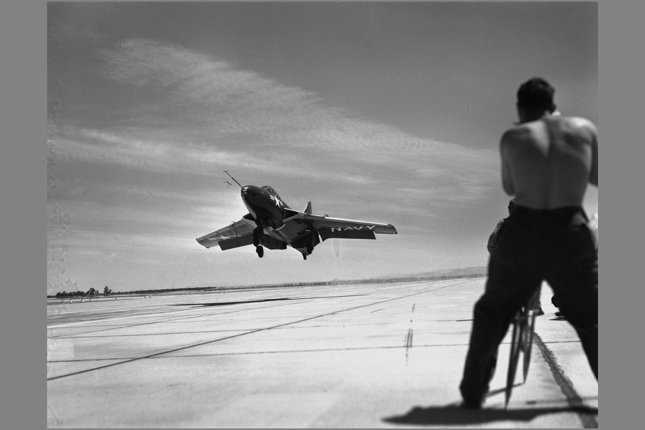
Grumman F9F-6 (Bu. No. 128138) Cougar airplane. EVALUATION OF CARRIER APPROACH TECHNIQUES Boundary Layer Control, STOL, and V/STOL Note: Used in publication in Flight Research at Ames; 57 Years of Development and Validation of Aeronautical Technology NASA SP-1998-3300 fig. 101
V/STOL Lift -cruise fan transport with Stan Dickenson in 40 x 80 ft. W. T.
3/4 front view of model with flaps up. V/STOL Aircraft: Wind tunnel investigation of rotating cylinder applied to training edge flaps for high lift & low-speed control.
3/4 rear view of model with flaps down. V/STOL Aircraft: Wind tunnel investigation of rotating cylinder applied to training edge flaps for high lift & low-speed control.

3/4 rear view of model with flaps down with Cecil E. MacDonald. V/STOL Aircraft: Wind tunnel investigation of rotating cylinder applied to training edge flaps for high lift & low-speed control.
6 degree V/STOL Control Systems Research All Axes, Simulator (simulator pilot: Richard K Greif) at the Ames Research Center, Moffett Field, CA Note: Used in publication in Flight Research at Ames; 57 Years of Development and Validation of Aeronautical Technology NASA SP-1998-3300 fig. 113
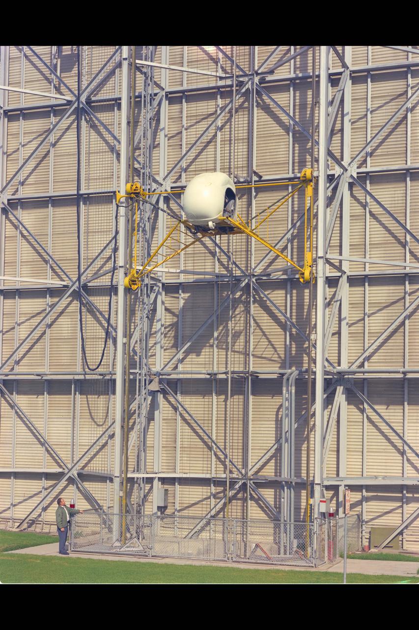
Height-Control Test Apparatus (HICONTA) Simulator mounted to the exterior of the 40x80ft W.T. Building N-221B and provided extensive vertical motion simulating airplanes, helicopter and V/STOL aircraft
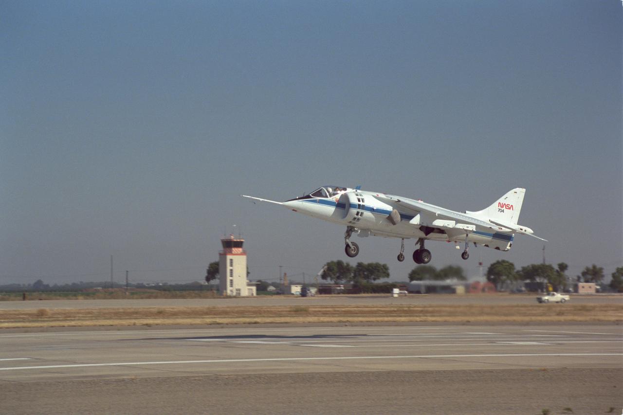
AV-8B Harrier V/STOL Aircraft NASA-704 take off at the NASA Ames facillity Crows Landing, CA
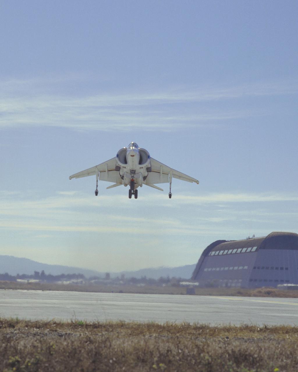
McDonnell Douglas YAV-8B (Bu. No. 158394 NASA 704 VSRA) Harrier V/STOL Systems Research Aircraft hover Note: Used in publication in Flight Research at Ames; 57 Years of Development and Validation of Aeronautical Technology NASA SP-1998-3300 fig.125
3/4 front right side only with Tim Wills on right and Charles Greco, mechanic. Large flaps on Variable height struts. XC-142 was a tri-service tiltwing experimental aircraft designed to investigate the operational suitability of vertical/short takeoff and landing (V/STOL) transports.
Bell V/STOL X-14 airplane mounted at 90 degrees yaw in 40x80 foot wind tunnel.
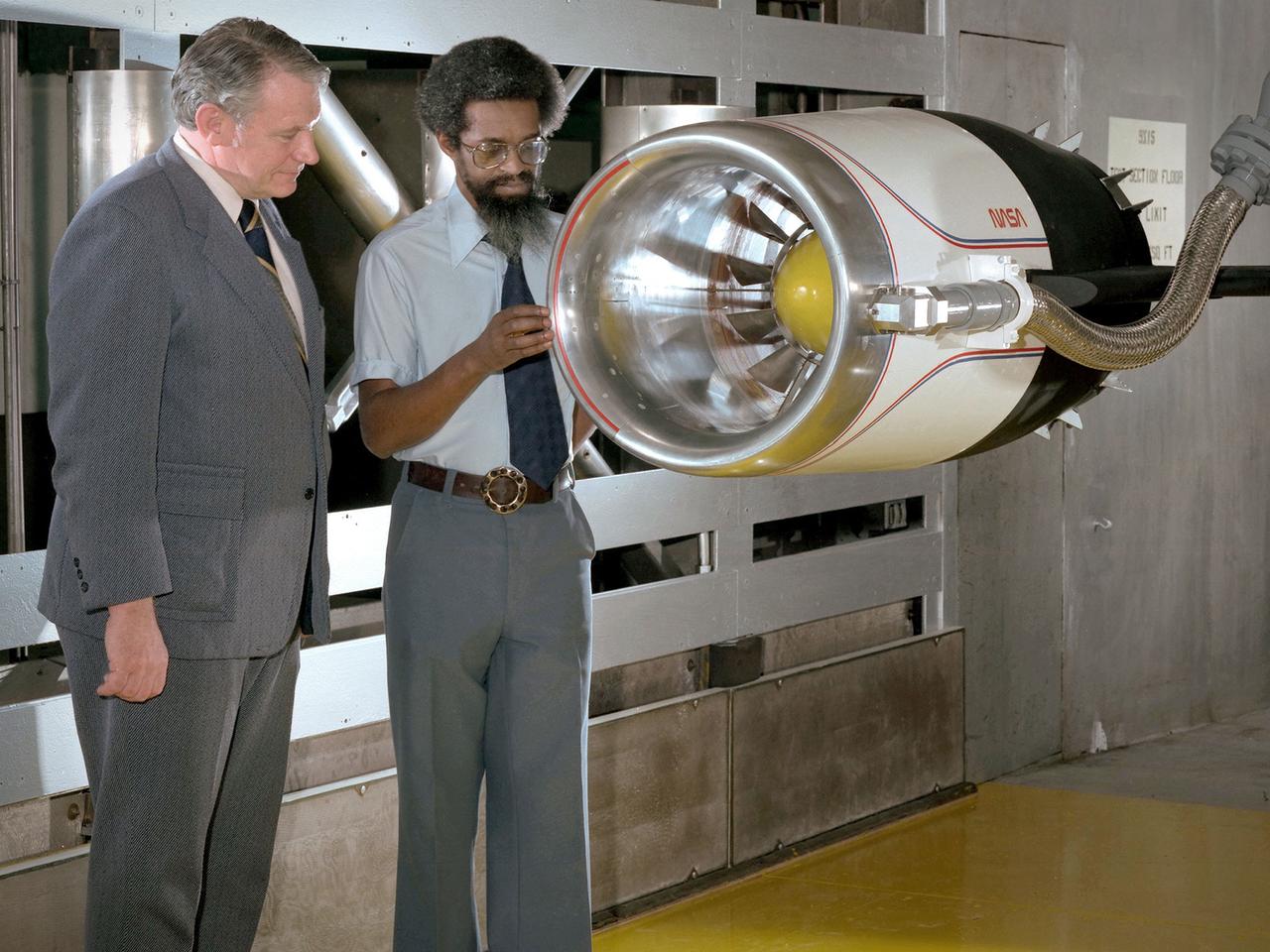
Center Director John McCarthy, left, and researcher Al Johns pose with a one-third scale model of a Grumman Aerospace tilt engine nacelle for Vertical and Short Takeoff and Landing (V/STOL) in the 9- by 15-Foot Low Speed Wind Tunnel at the National Aeronautics and Space Administration (NASA) Lewis Research Center. Lewis researchers had been studying tilt nacelle and inlet issues for several years. One area of concern was the inlet flow separation during the transition from horizontal to vertical flight. The separation of air flow from the inlet’s internal components could significantly stress the fan blades or cause a loss of thrust. In 1978 NASA researchers Robert Williams and Al Johns teamed with Grumman’s H.C. Potonides to develop a series of tests in the Lewis 9- by 15-foot tunnel to study a device designed to delay the flow separation by blowing additional air into the inlet. A jet of air, supplied through the hose on the right, was blown over the inlet surfaces. The researchers verified that the air jet slowed the flow separation. They found that the blowing on boundary layer control resulted in a doubling of the angle-of-attack and decreases in compressor blade stresses and fan distortion. The tests were the first time the concept of blowing air for boundary layer control was demonstrated. Boundary layer control devices like this could result in smaller and lighter V/STOL inlets.
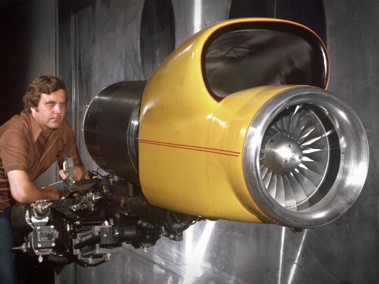
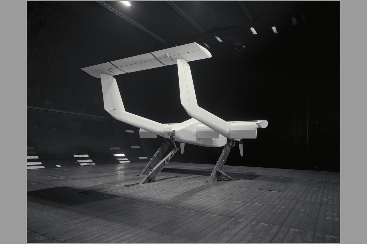
A technician checks a 0.25-scale engine model of a Vought Corporation V-530 engine in the test section of the 10- by 10-Foot Supersonic Wind Tunnel at the National Aeronautics and Space Administration (NASA) Lewis Research Center. Vought created a low-drag tandem-fan Vertical/Short and Takeoff and Landing (V/STOL) engine in the mid-1970s, designated as the V-530. The first fan on the tandem-fan engine was supplied with air through a traditional subsonic inlet, seen on the lower front of the engine. The air was exhausted through the nacelle during normal flight and directed down during takeoffs. The rear fan was supplied by the oval-shaped top inlet during all phases of the flight. The second fan exhausted its air through a rear vectorable nozzle. NASA Lewis and Vought partnered in the late 1970s to collect an array of inlet and nozzle design information on the tandem fan engines for the Navy. Vought created this .25-scale model of the V-530 for extensive testing in Lewis' 10- by 10-foot tunnel. During an early series of tests, the front fan was covered, and a turbofan simulator was used to supply air to the rear fan. The researchers then analyzed the performance of only the front fan inlet. During the final series of tests, the flow from the front fan was used to supply airflow to the rear fan. The researchers studied the inlet's recovery, distortion, and angle-of-attack limits over various flight conditions.
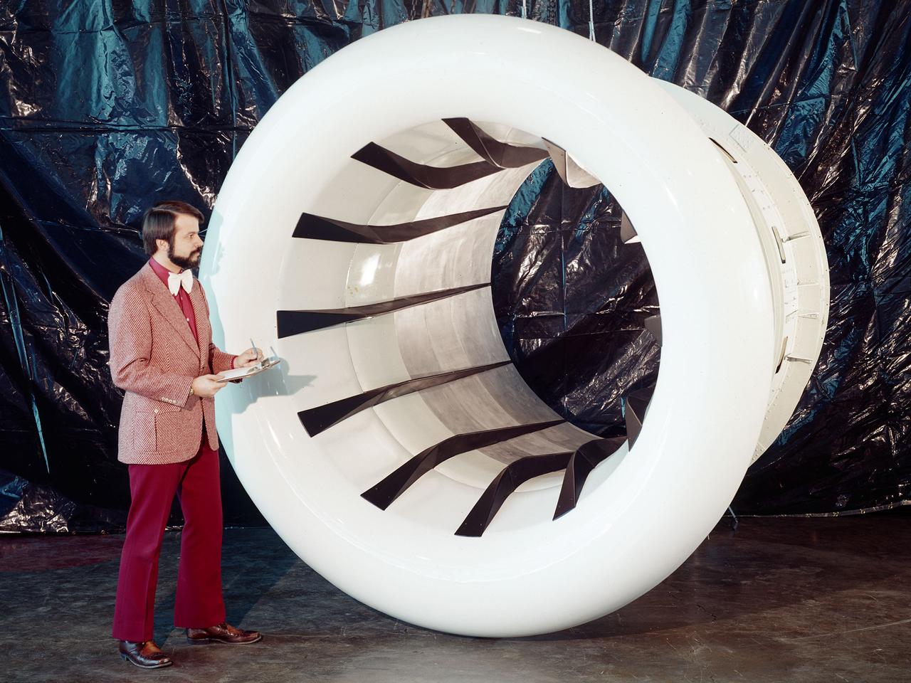
Brent Miller, of the V/STOL and Noise Division at the National Aeronautics and Space Administration (NASA) Lewis Research Center, poses with a sonic inlet for the NASA Quiet Engine Program. NASA Lewis had first investigated methods for reducing aircraft engine noise in the mid-1950s. Those efforts were resurrected and expanded in the late 1960s. The researchers found that the use of a sonic, or high-throat-Mach-number, inlet was effective at reducing the noise from the engine inlet. The device accelerated the inlet air to near-sonic speeds which kept the forward moving sound waves away from the inlet. The device also deflected the sound waves into the wall to further reduce the noise. NASA Lewis researchers tested models of the sonic inlet in their 9- by 15-Foot Low Speed Wind Tunnel. They found that the general level of aerodynamic performance was good. The tests during simulated takeoff and landing conditions demonstrated the sonic inlet’s ability to provide good aerodynamic and acoustic performance The researchers then successfully tested two full-scale sonic inlet designs, one from Pratt and Whitney and one from General Electric, with fans. A full-scale engine was installed on a thrust stand to determine the sonic inlet’s effect on the engine’s performance. The amount of noise reduction increased as the inlet flow velocity increased, but the full-scale tests did not produce as great a decrease in noise as the earlier small-scale tests.