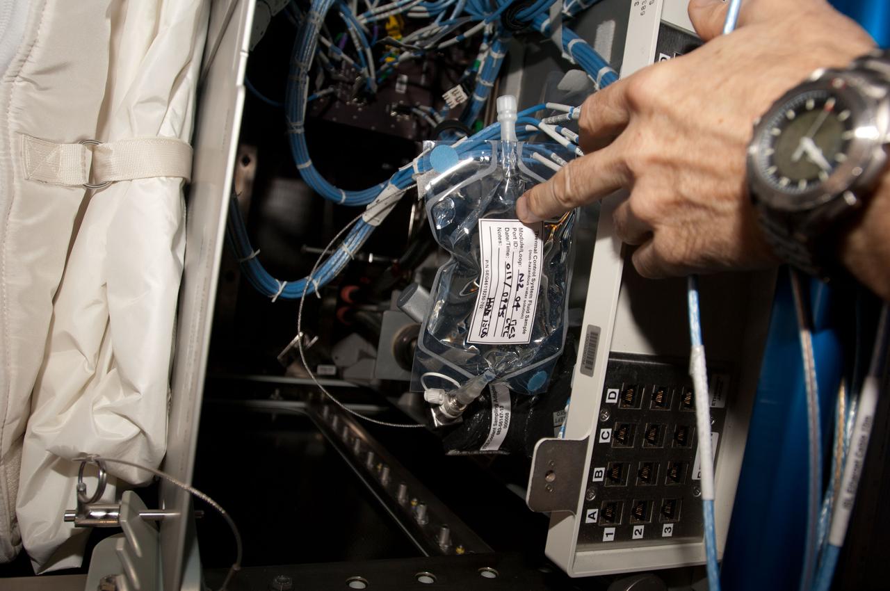
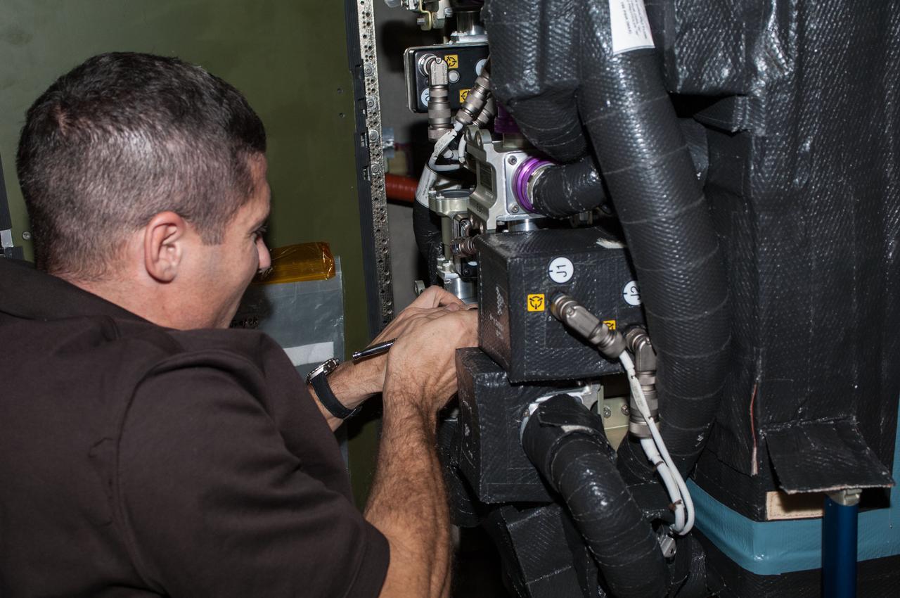
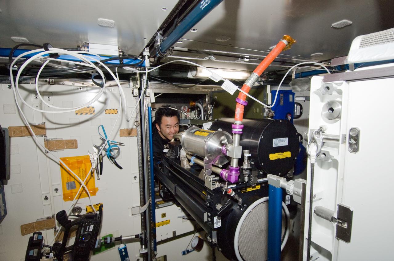
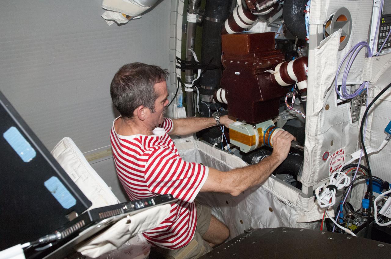
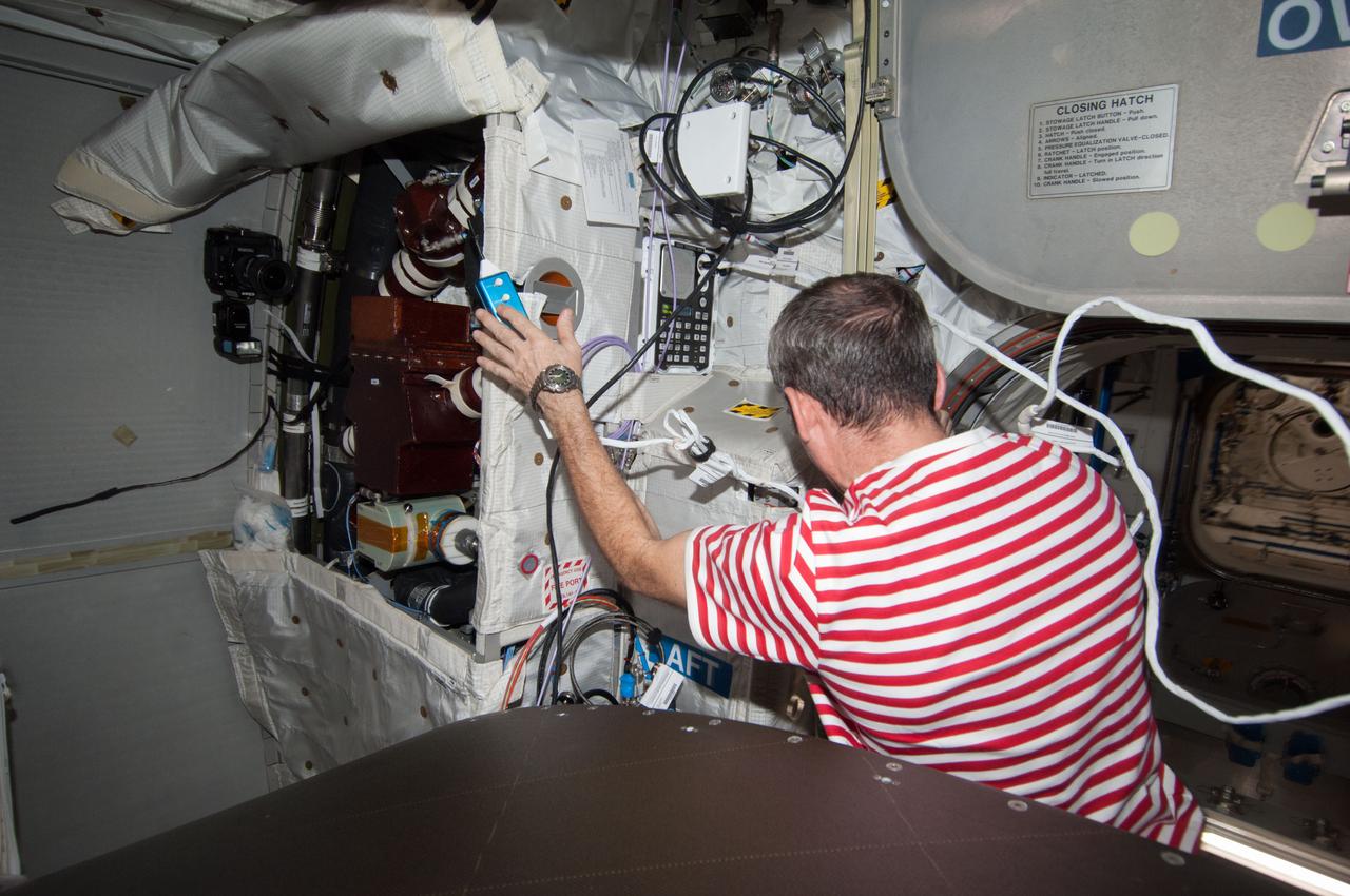
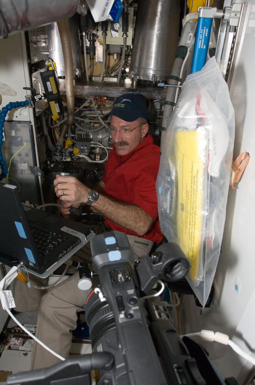
View during Internal Thermal Control System (ITCS) - Measuring valve parameters in the Node 3. Photo was taken during Expedition 34.
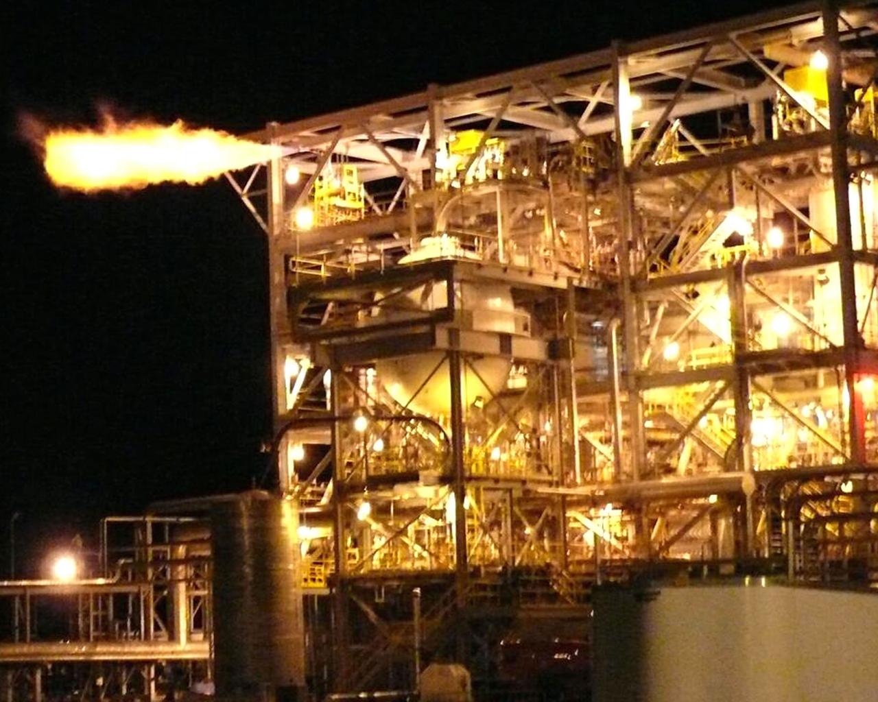
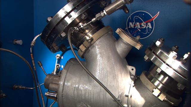
Flames burst from the E-1 Test Stand as Stennis Space Center engineers perform one of dozens of shuttle flow valve tests in early February. Stennis engineers teamed with Innovative Partnership Program partners to perform the tests after NASA officials delayed the launch of the STS-119 mission because of concerns with the shuttle part.
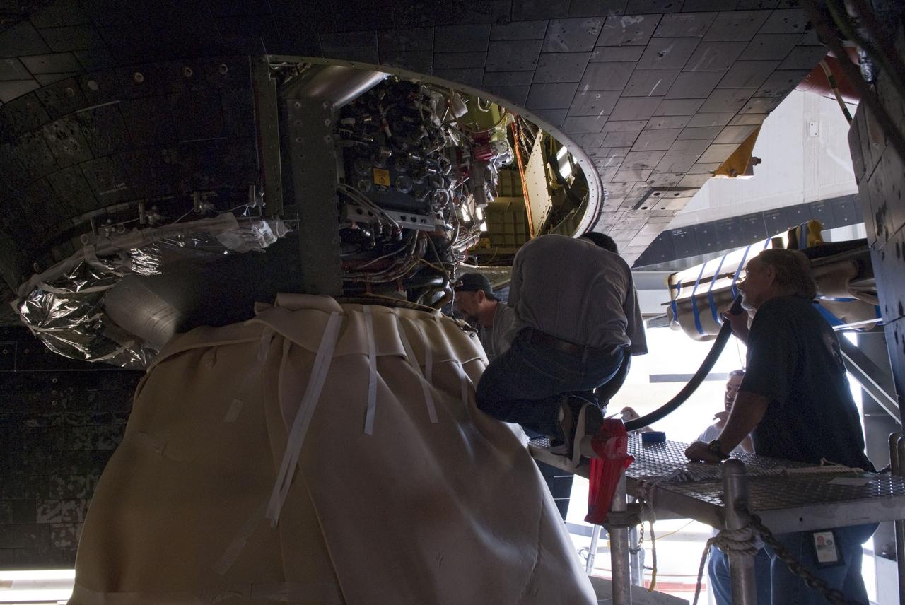
CAPE CANAVERAL, Fla. – On Launch Pad 39A at NASA's Kennedy Space Center in Florida, technicians have removed space shuttle Discovery's three gaseous hydrogen flow control valves, two of which will undergo detailed inspection. Part of the main propulsion system, the valves channel gaseous hydrogen from the main engines to the external tank. NASA and contractor teams have been working to identify what caused damage to a flow control valve on shuttle Endeavour during its November 2008 flight. Approximately 4,000 images of each valve removed will be reviewed for evidence of cracks. Valves that have flown fewer times will be installed in Discovery. NASA's Space Shuttle Program has established a plan that could support shuttle Discovery's launch to the International Space Station, tentatively targeted for March 12. An exact target launch date will be determined as work on the valves progresses. Photo credit: NASA/Dimitri Gerondidakis
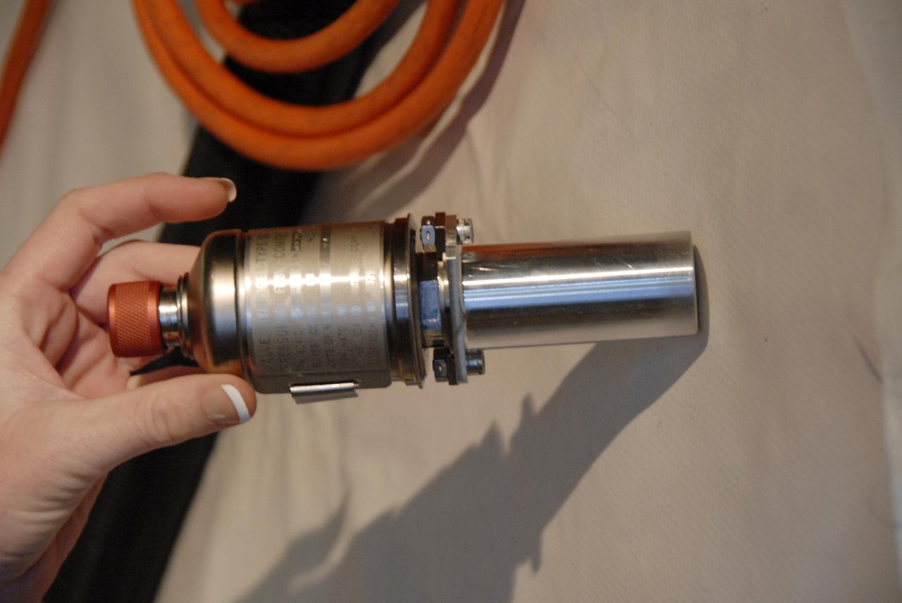
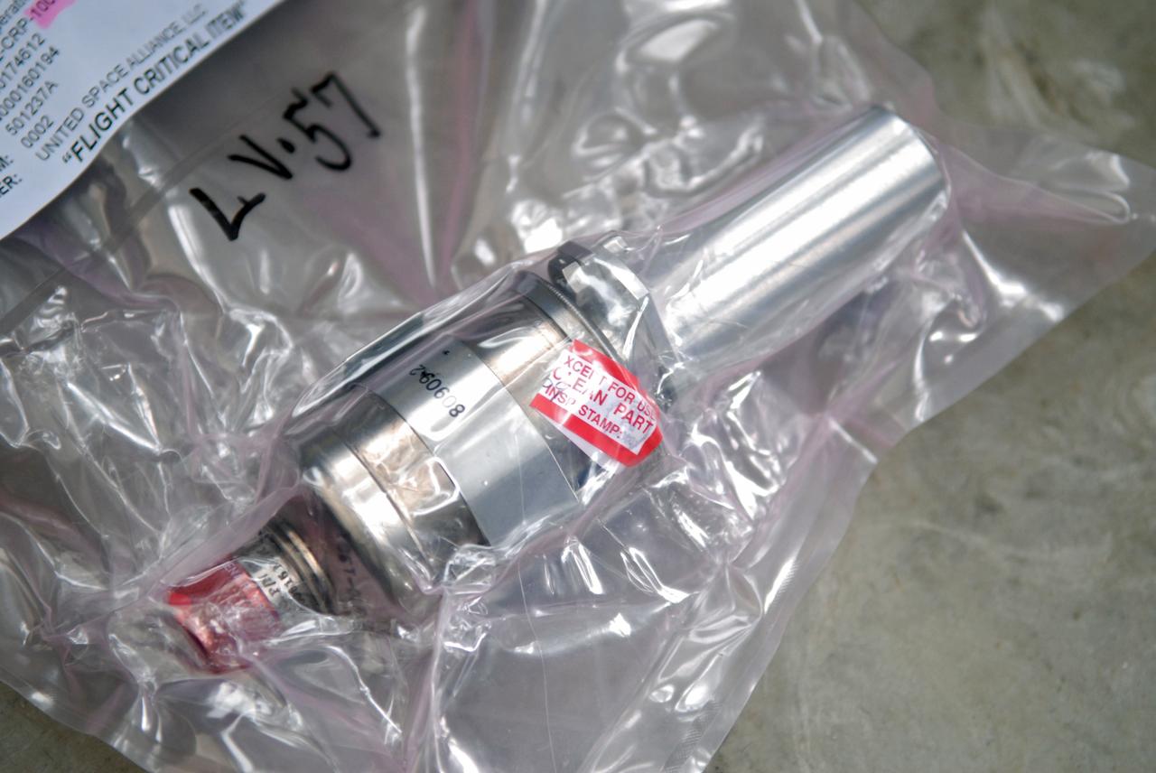
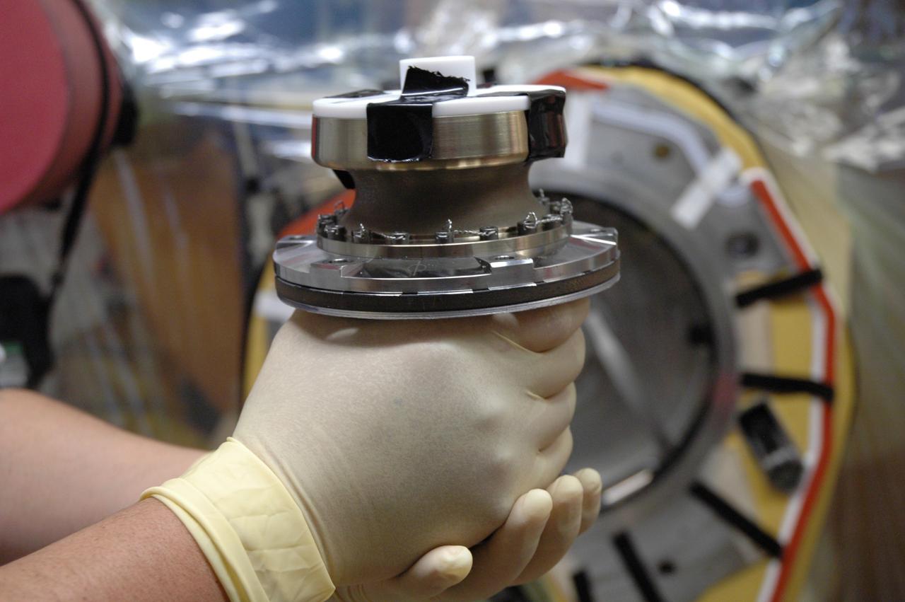
CAPE CANAVERAL, Fla. – On Launch Pad 39A at NASA's Kennedy Space Center in Florida, a technician holds one of space shuttle Discovery's gaseous hydrogen flow control valves after its removal. Two of the three valves being removed will undergo detailed inspection. Part of the main propulsion system, the valves channel gaseous hydrogen from the main engines to the external tank. NASA and contractor teams have been working to identify what caused damage to a flow control valve on shuttle Endeavour during its November 2008 flight. Approximately 4,000 images of each valve removed will be reviewed for evidence of cracks. Valves that have flown fewer times will be installed in Discovery. NASA's Space Shuttle Program has established a plan that could support shuttle Discovery's launch to the International Space Station, tentatively targeted for March 12. An exact target launch date will be determined as work on the valves progresses. Photo credit: NASA/Dimitri Gerondidakis
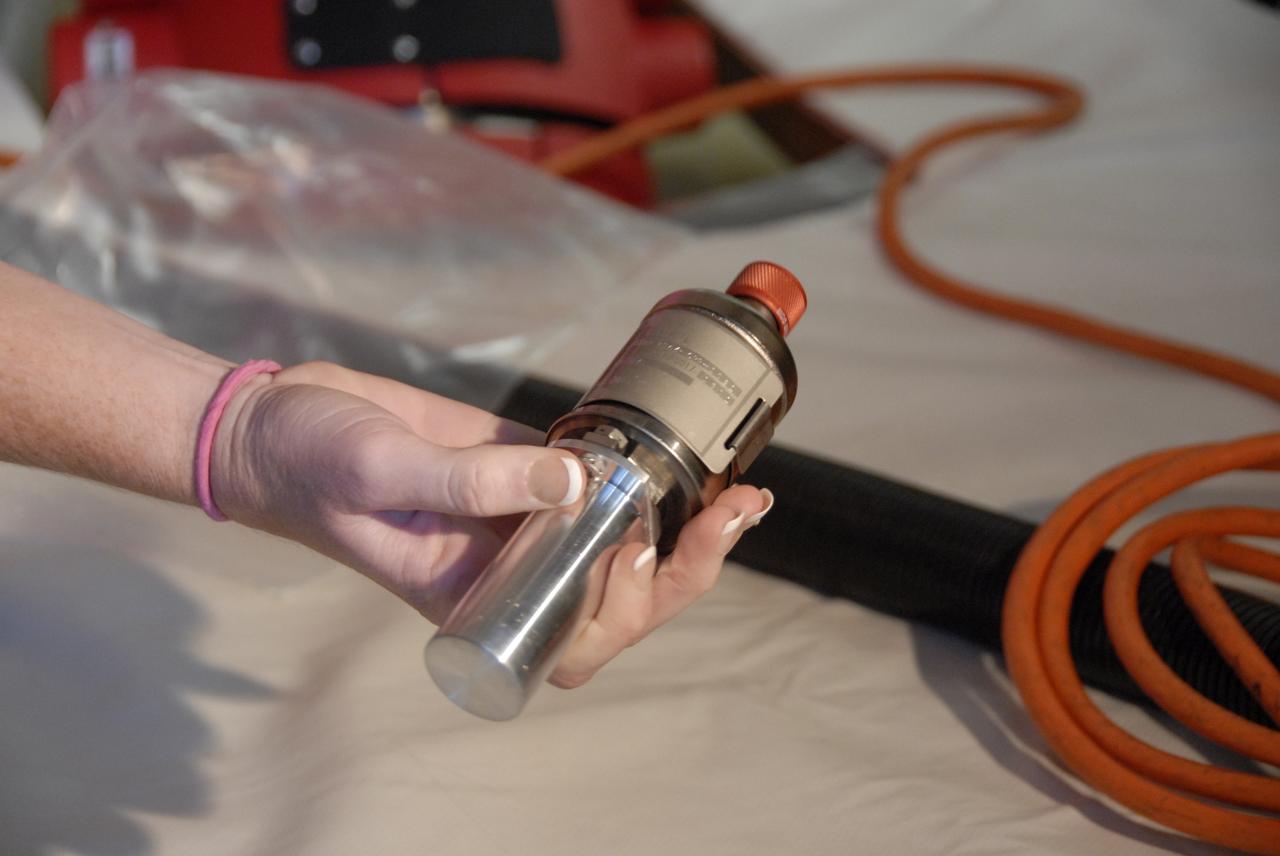
CAPE CANAVERAL, Fla. – On Launch Pad 39A at NASA's Kennedy Space Center in Florida, a technician holds one of space shuttle Discovery's gaseous hydrogen flow control valves after its removal. Two of the three valves being removed will undergo detailed inspection. Part of the main propulsion system, the valves channel gaseous hydrogen from the main engines to the external tank. NASA and contractor teams have been working to identify what caused damage to a flow control valve on shuttle Endeavour during its November 2008 flight. Approximately 4,000 images of each valve removed will be reviewed for evidence of cracks. Valves that have flown fewer times will be installed in Discovery. NASA's Space Shuttle Program has established a plan that could support shuttle Discovery's launch to the International Space Station, tentatively targeted for March 12. An exact target launch date will be determined as work on the valves progresses. Photo credit: NASA/Dimitri Gerondidakis
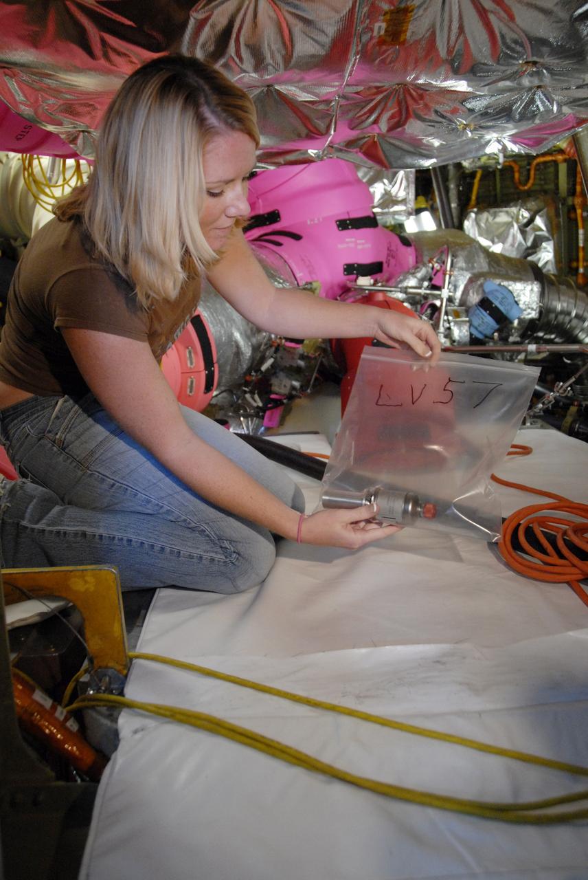
CAPE CANAVERAL, Fla. – On Launch Pad 39A at NASA's Kennedy Space Center in Florida, a technician bags one of space shuttle Discovery's gaseous hydrogen flow control valves after its removal. Two of the three valves being removed will undergo detailed inspection. Part of the main propulsion system, the valves channel gaseous hydrogen from the main engines to the external tank. NASA and contractor teams have been working to identify what caused damage to a flow control valve on shuttle Endeavour during its November 2008 flight. Approximately 4,000 images of each valve removed will be reviewed for evidence of cracks. Valves that have flown fewer times will be installed in Discovery. NASA's Space Shuttle Program has established a plan that could support shuttle Discovery's launch to the International Space Station, tentatively targeted for March 12. An exact target launch date will be determined as work on the valves progresses. Photo credit: NASA/Dimitri Gerondidakis

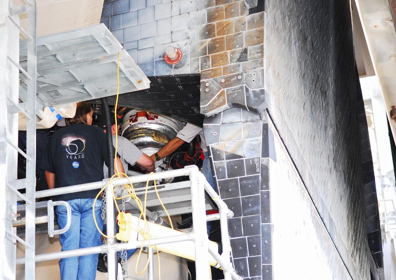
CAPE CANAVERAL, Fla. – On Launch Pad 39A at NASA's Kennedy Space Center in Florida, technicians install three gaseous hydrogen flow control valves on space shuttle Discovery. The valves were retested after installation. Part of the main propulsion system, the valves channel gaseous hydrogen from the main engines to the external tank. NASA and contractor teams have worked to identify what caused damage to a flow control valve on shuttle Endeavour during its November 2008 flight. Space Shuttle Program managers decided to replace Discovery's valves with others that have undergone a detailed eddy current inspection. Program managers will review the testing and determine whether to meet on March 6 for the Flight Readiness Review for the STS-119 mission. Launch of Discovery tentatively is targeted for March 12. Photo credit: NASA/Chris Rhodes
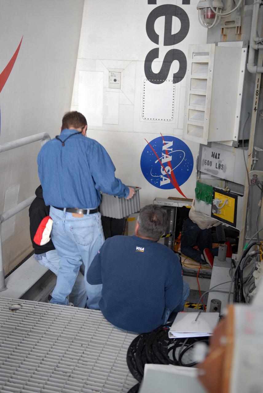
CAPE CANAVERAL, Fla. – On Launch Pad 39A at NASA's Kennedy Space Center in Florida, technicians prepare to install three gaseous hydrogen flow control valves on space shuttle Discovery. The valves were retested after installation. Part of the main propulsion system, the valves channel gaseous hydrogen from the main engines to the external tank. NASA and contractor teams have worked to identify what caused damage to a flow control valve on shuttle Endeavour during its November 2008 flight. Space Shuttle Program managers decided to replace Discovery's valves with others that have undergone a detailed eddy current inspection. Program managers will review the testing and determine whether to meet on March 6 for the Flight Readiness Review for the STS-119 mission. Launch of Discovery tentatively is targeted for March 12. Photo credit: NASA/Chris Rhodes

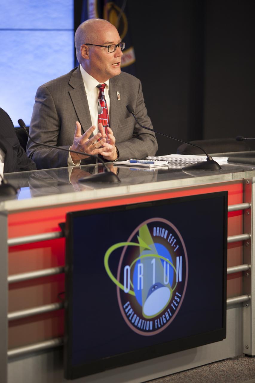
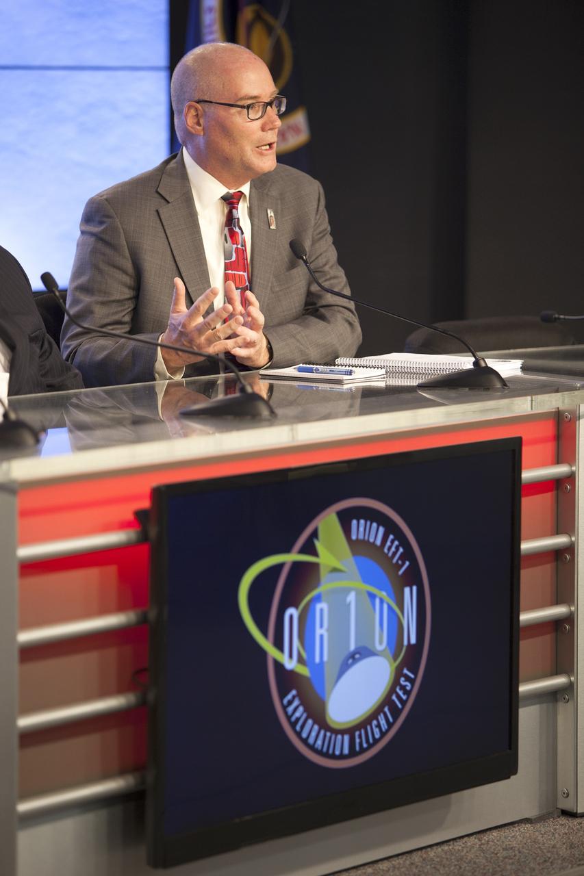
CAPE CANAVERAL, Fla. – At the flight readiness review news conference for space shuttle Discovery's STS-119 mission, Space Shuttle Program Manager John Shannon (right) talks about the discussion surrounding Discovery's readiness for flight. At left is Associate Administrator for Space Operations Bill Gerstenmaier. Shannon is holding a flow control valve that is under review and testing. Engineering teams have been working to identify what caused damage to a flow control valve on shuttle Endeavour during its November 2008 flight. A new launch date has not been determined. Photo credit: NASA/Glenn Benson
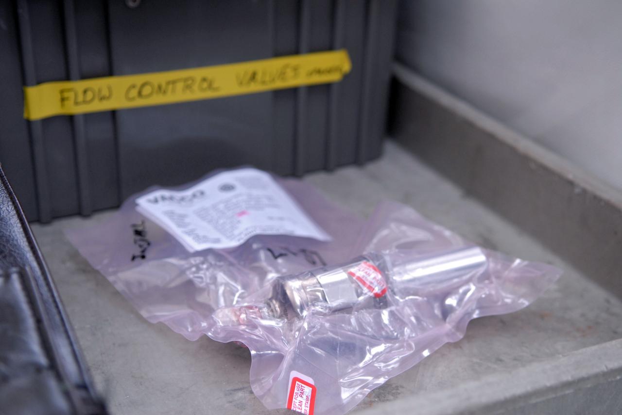
CAPE CANAVERAL, Fla. – One of the three thoroughly inspected gaseous hydrogen flow control valves is shown after its arrival at NASA's Kennedy Space Center in Florida. Technicians installed and retested them in space shuttle Discovery. Part of the main propulsion system, the valves channel gaseous hydrogen from the main engines to the external tank. NASA and contractor teams have worked to identify what caused damage to a flow control valve on shuttle Endeavour during its November 2008 flight. Space Shuttle Program managers decided to replace Discovery's valves with others that have undergone a detailed eddy current inspection. Program managers will review the testing and determine whether to meet on March 6 for the Flight Readiness Review for the STS-119 mission. Launch of Discovery tentatively is targeted for March 12. Photo credit: NASA/Chris Rhodes
CAPE CANAVERAL, Fla. – One of the three thoroughly inspected gaseous hydrogen flow control valves is shown after its arrival at NASA's Kennedy Space Center in Florida. Technicians installed and retested them in space shuttle Discovery. Part of the main propulsion system, the valves channel gaseous hydrogen from the main engines to the external tank. NASA and contractor teams have worked to identify what caused damage to a flow control valve on shuttle Endeavour during its November 2008 flight. Space Shuttle Program managers decided to replace Discovery's valves with others that have undergone a detailed eddy current inspection. Program managers will review the testing and determine whether to meet on March 6 for the Flight Readiness Review for the STS-119 mission. Launch of Discovery tentatively is targeted for March 12. Photo credit: NASA/Chris Rhodes
CAPE CANAVERAL, Fla. -- During a tanking test on June 15 at Launch Pad 39A at NASA's Kennedy Space Center in Florida, there was an apparent liquid hydrogen leak in the main fuel valve in Atlantis' space shuttle main engine No. 3. Technicians now are replacing the suspect valve and a leak check of the valve and associated systems will be conducted. The work is expected to take about a week, which still would support Atlantis' targeted July 8 launch date. STS-135 Commander Chris Ferguson, Pilot Doug Hurley and Mission Specialists Sandy Magnus and Rex Walheim are targeted to lift off on space shuttle Atlantis July 8, taking with them the MPLM packed with supplies, logistics and spare parts to the International Space Station. The STS-135 mission also will fly a system to investigate the potential for robotically refueling existing satellites and return a failed ammonia pump module to help NASA better understand the failure mechanism and improve pump designs for future systems. STS-135 will be the 33rd flight of Atlantis, the 37th shuttle mission to the space station, and the 135th and final mission of NASA's Space Shuttle Program. For more information visit, www.nasa.gov/mission_pages/shuttle/shuttlemissions/sts135/index.html. Photo credit: NASA/Jim Grossmann
CAPE CANAVERAL, Fla. -- During a tanking test on June 15 at Launch Pad 39A at NASA's Kennedy Space Center in Florida, there was an apparent liquid hydrogen leak in the main fuel valve in Atlantis' space shuttle main engine No. 3. Technicians now are replacing the suspect valve and a leak check of the valve and associated systems will be conducted. The work is expected to take about a week, which still would support Atlantis' targeted July 8 launch date. STS-135 Commander Chris Ferguson, Pilot Doug Hurley and Mission Specialists Sandy Magnus and Rex Walheim are targeted to lift off on space shuttle Atlantis July 8, taking with them the MPLM packed with supplies, logistics and spare parts to the International Space Station. The STS-135 mission also will fly a system to investigate the potential for robotically refueling existing satellites and return a failed ammonia pump module to help NASA better understand the failure mechanism and improve pump designs for future systems. STS-135 will be the 33rd flight of Atlantis, the 37th shuttle mission to the space station, and the 135th and final mission of NASA's Space Shuttle Program. For more information visit, www.nasa.gov/mission_pages/shuttle/shuttlemissions/sts135/index.html. Photo credit: NASA/Jim Grossmann
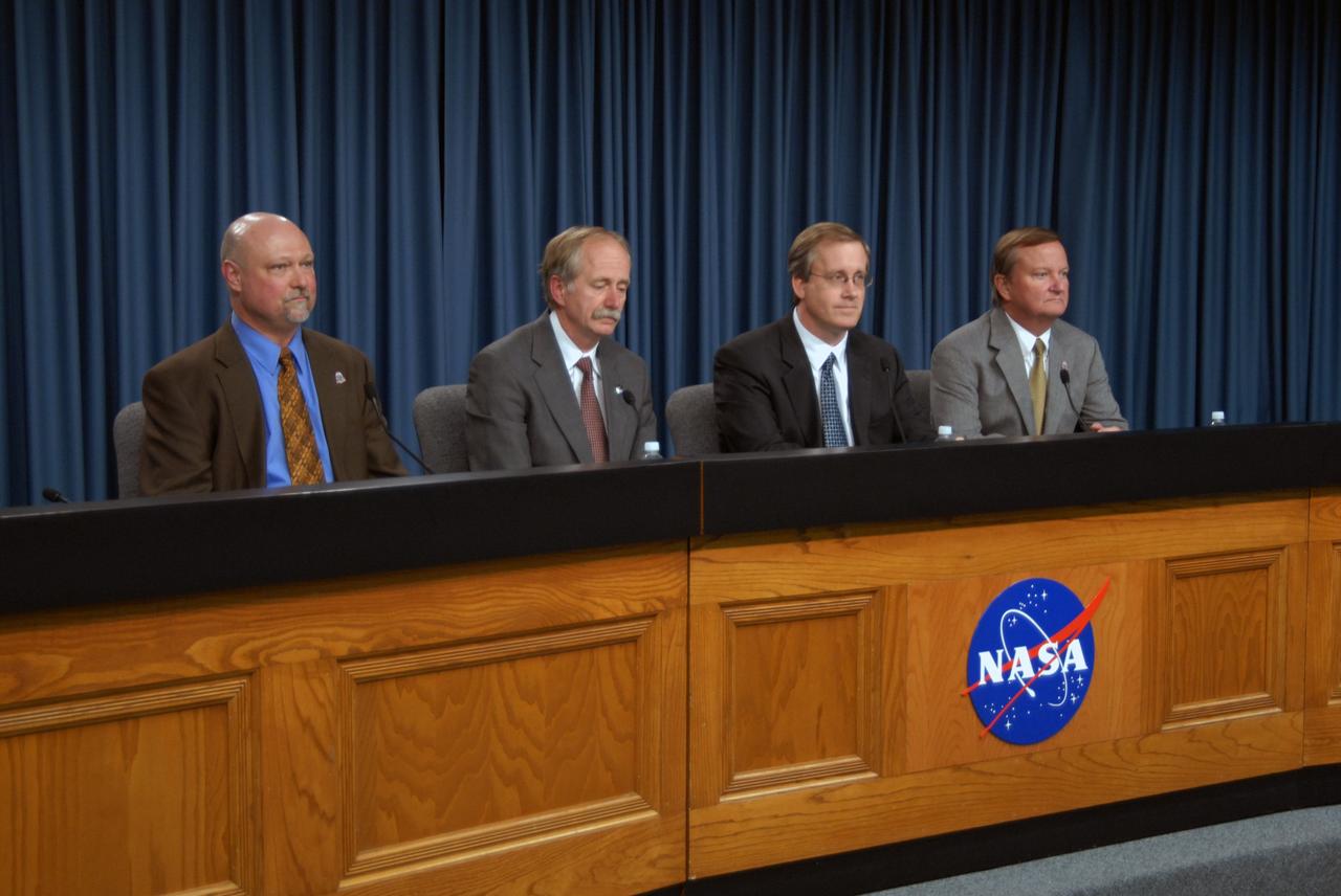
CAPE CANAVERAL, Fla. – Mike Curie (far left), with NASA Public Affairs, moderates the flight readiness review news conference for space shuttle Discovery's STS-119 mission. On the panel are (from left) Associate Administrator for Space Operations Bill Gerstenmaier, Space Shuttle Program Manager John Shannon and Space Shuttle Launch Director Mike Leinbach. During a thorough review of Discovery's readiness for flight, NASA managers decided Feb. 20 more data and possible testing are required before proceeding to launch. Engineering teams have been working to identify what caused damage to a flow control valve on shuttle Endeavour during its November 2008 flight. A new launch date has not been determined. NASA managers decided Feb. 20 more data and possible testing are required before proceeding to launch. Engineering teams have been working to identify what caused damage to a flow control valve on shuttle Endeavour during its November 2008 flight. A new launch date has not been determined. Photo credit: NASA/Glenn Benson

CAPE CANAVERAL, Fla. – At the flight readiness review news conference for space shuttle Discovery's STS-119 mission, Associate Administrator for Space Operations Bill Gerstenmaier talks about the review by mission managers of Discovery's readiness for flight. NASA managers decided Feb. 20 more data and possible testing are required before proceeding to launch. Engineering teams have been working to identify what caused damage to a flow control valve on shuttle Endeavour during its November 2008 flight. A new launch date has not been determined. Photo credit: NASA/Glenn Benson

CAPE CANAVERAL, Fla. – At the flight readiness review news conference for space shuttle Discovery's STS-119 mission, Space Shuttle Program Manager John Shannon talks about the discussion surrounding Discovery's readiness for flight. NASA managers decided Feb. 20 more data and possible testing are required before proceeding to launch. Engineering teams have been working to identify what caused damage to a flow control valve on shuttle Endeavour during its November 2008 flight. A new launch date has not been determined. Photo credit: NASA/Glenn Benson
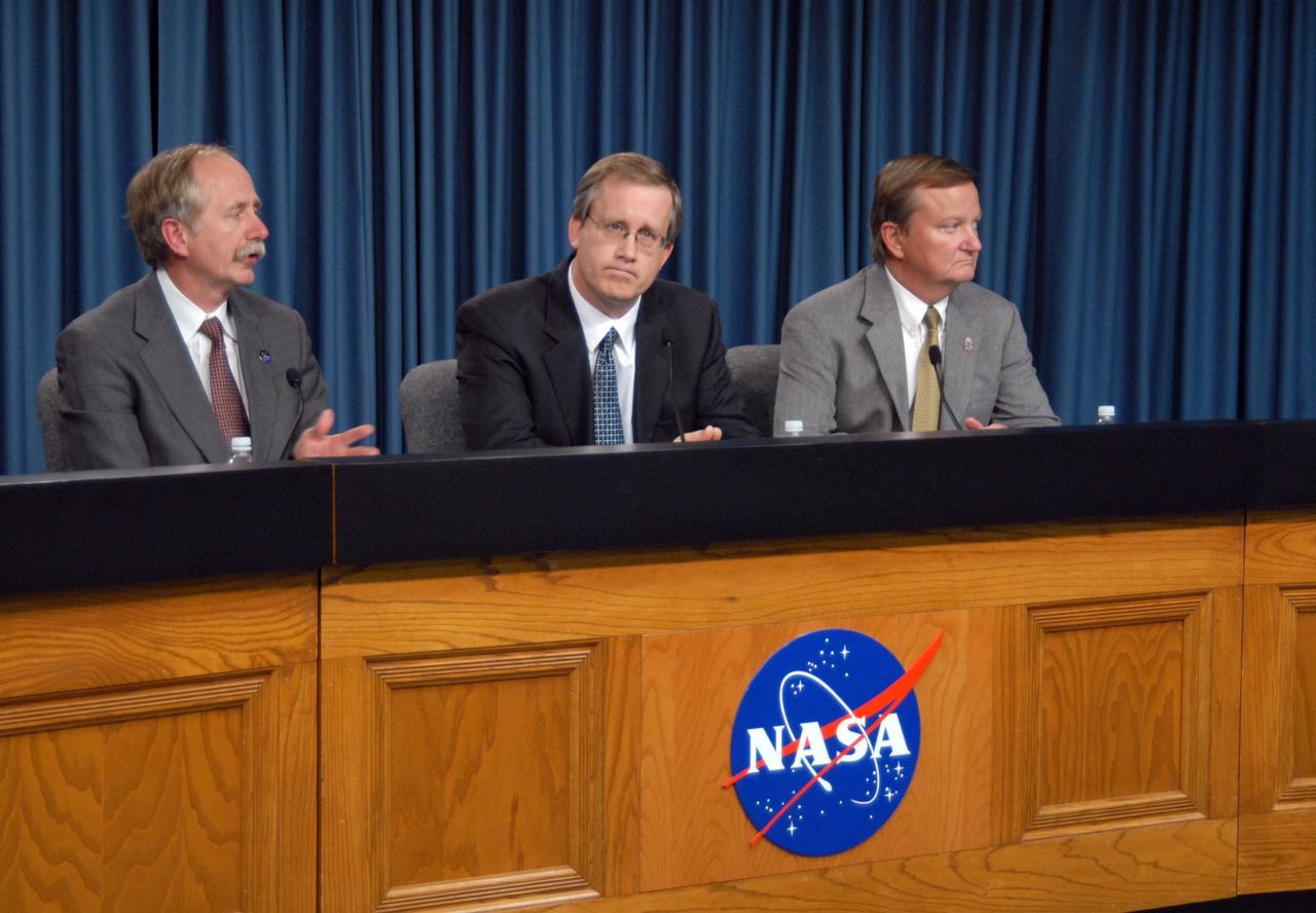
CAPE CANAVERAL, Fla. – Associate Administrator for Space Operations Bill Gerstenmaier, Space Shuttle Program Manager John Shannon and Space Shuttle Launch Director Mike Leinbach respond to media questions about the flight readiness review news conference for space shuttle Discovery's STS-119 mission. NASA managers decided Feb. 20 more data and possible testing are required before proceeding to launch. Engineering teams have been working to identify what caused damage to a flow control valve on shuttle Endeavour during its November 2008 flight. A new launch date has not been determined. Photo credit: NASA/Glenn Benson

CAPE CANAVERAL, Fla. – At the flight readiness review news conference for space shuttle Discovery's STS-119 mission, Space Shuttle Program Manager John Shannon (right) talks about the discussion surrounding Discovery's readiness for flight. At left is Associate Administrator for Space Operations Bill Gerstenmaier. NASA managers decided Feb. 20 more data and possible testing are required before proceeding to launch. Engineering teams have been working to identify what caused damage to a flow control valve on shuttle Endeavour during its November 2008 flight. A new launch date has not been determined. Photo credit: NASA/Glenn Benson
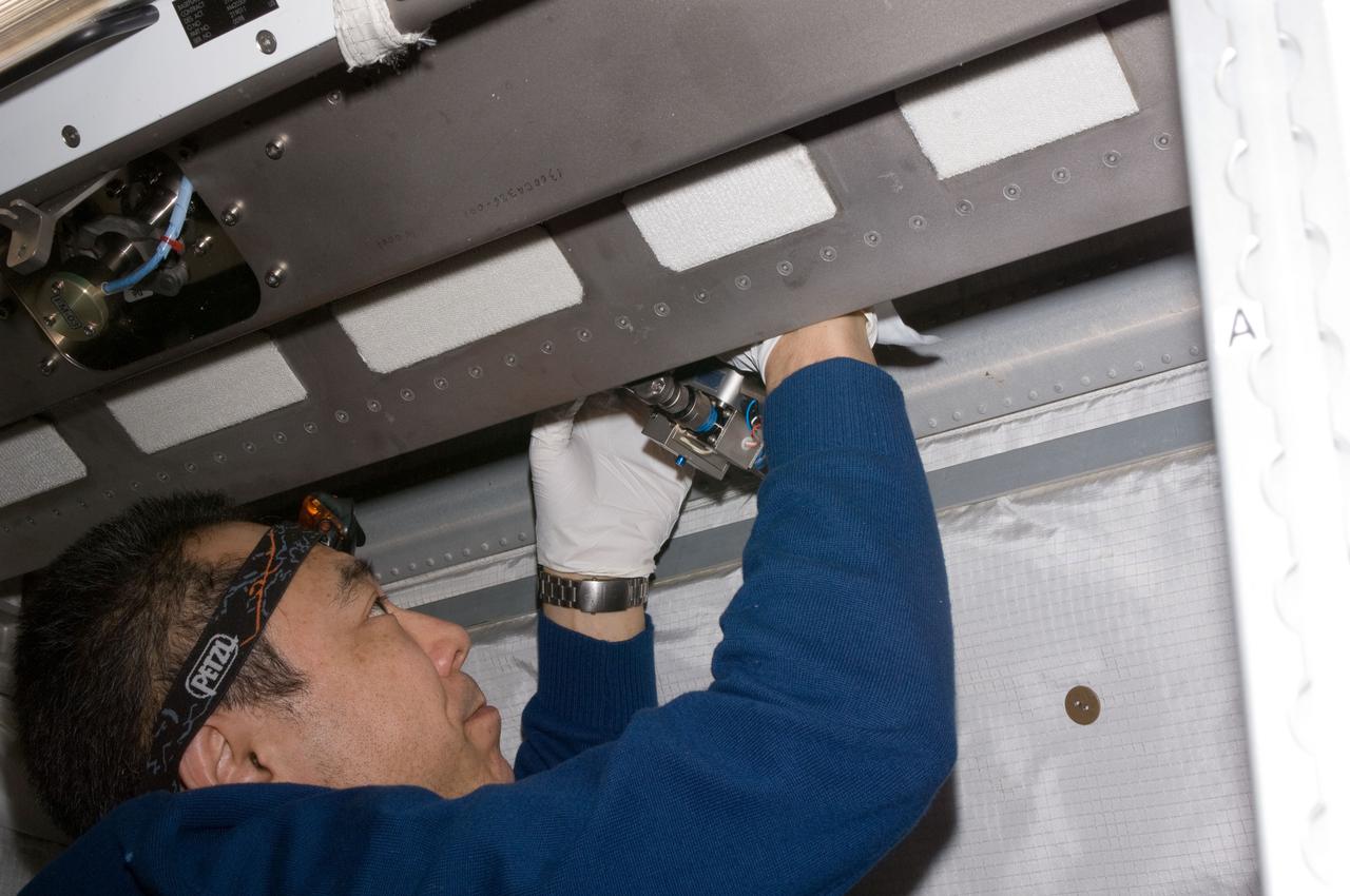
ISS029-E-027341 (14 Oct. 2011) --- In the International Space Station’s Columbus laboratory, Japan Aerospace Exploration Agency astronaut Satoshi Furukawa, Expedition 29 flight engineer, works on Water On/Off Valves (WOOV), performing inspection, cleaning, disinfection and encapsulation on WOOV 3, 4 and 5.
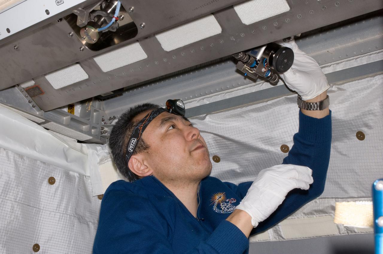
ISS029-E-027343 (14 Oct. 2011) --- In the International Space Station’s Columbus laboratory, Japan Aerospace Exploration Agency astronaut Satoshi Furukawa, Expedition 29 flight engineer, works on Water On/Off Valves (WOOV), performing inspection, cleaning, disinfection and encapsulation on WOOV 3, 4 and 5.
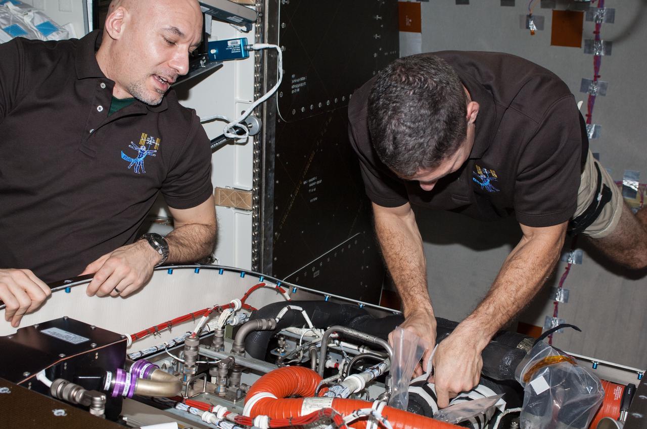
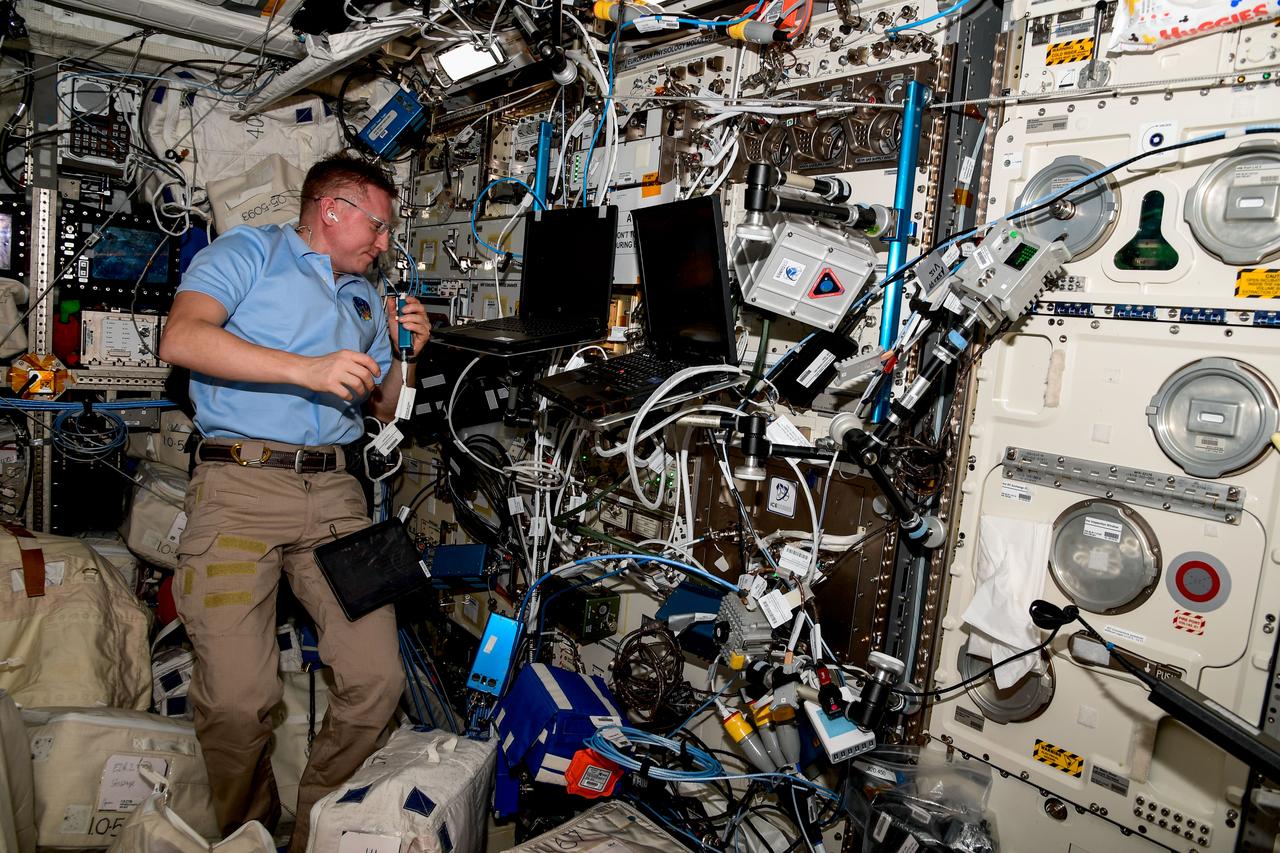
ISS037-E-021985 (28 Oct. 2013) --- In the International Space Station?s Tranquility node, NASA astronaut Michael Hopkins (right) and European Space Agency astronaut Luca Parmitano, both Expedition 37 flight engineers, perform routine in-flight maintenance within the Carbon Dioxide Removal Assembly. This device removes carbon dioxide from the station?s atmosphere and is part of the station?s Environmental Control and Life Support System that provides clean water and air to the crew.
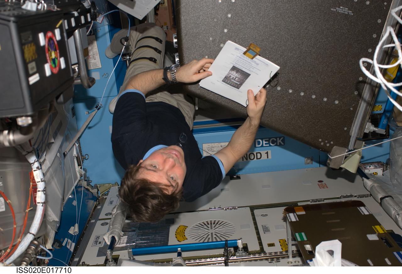
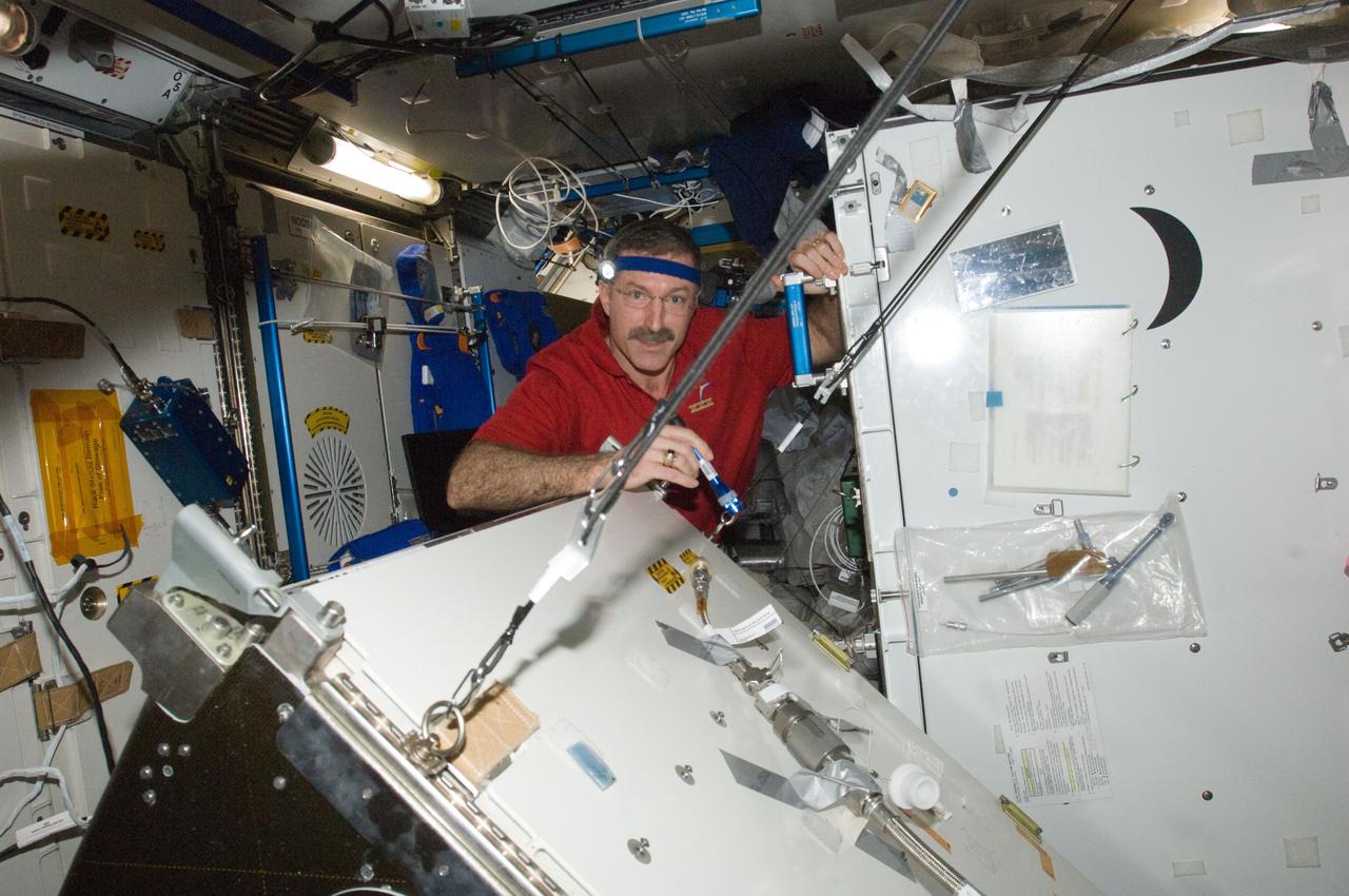
ISS020-E-017710 (7 July 2009) --- NASA astronaut Michael Barratt, Expedition 20 flight engineer, works at a rotated rack in the Destiny laboratory of the International Space Station during in-flight maintenance (IFM) to adjust the periodic flow rate of manual flow control valves for coolant loops.
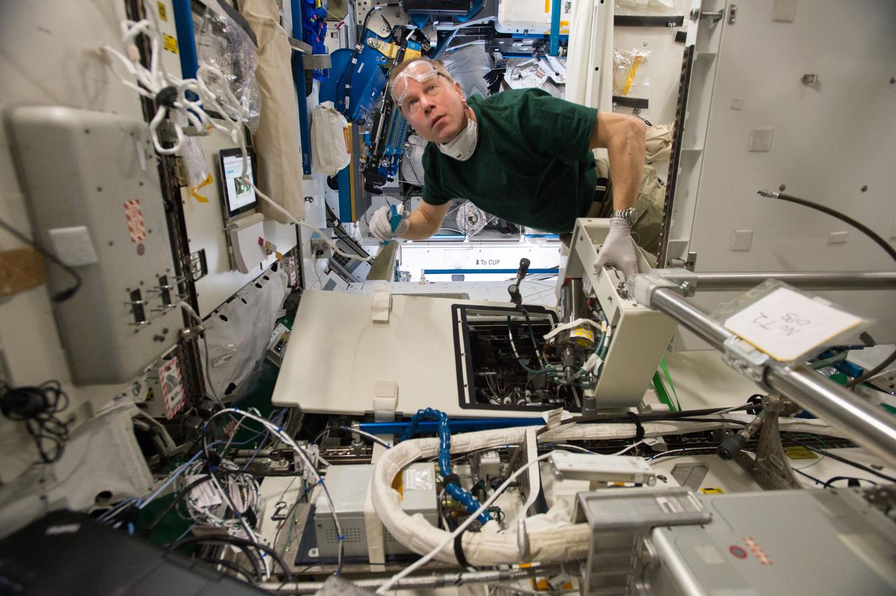
ISS046e023885 (01/25/2016) --- NASA astronaut Tim Kopra performs regular maintenance on the Urine Processing Assembly (UPA) aboard the International Space Station. The UPA is used by the crew to recycle water for use on the station. The image shows Tim replacing the brine filter from the UPA Fill Drain Valve enclosure.
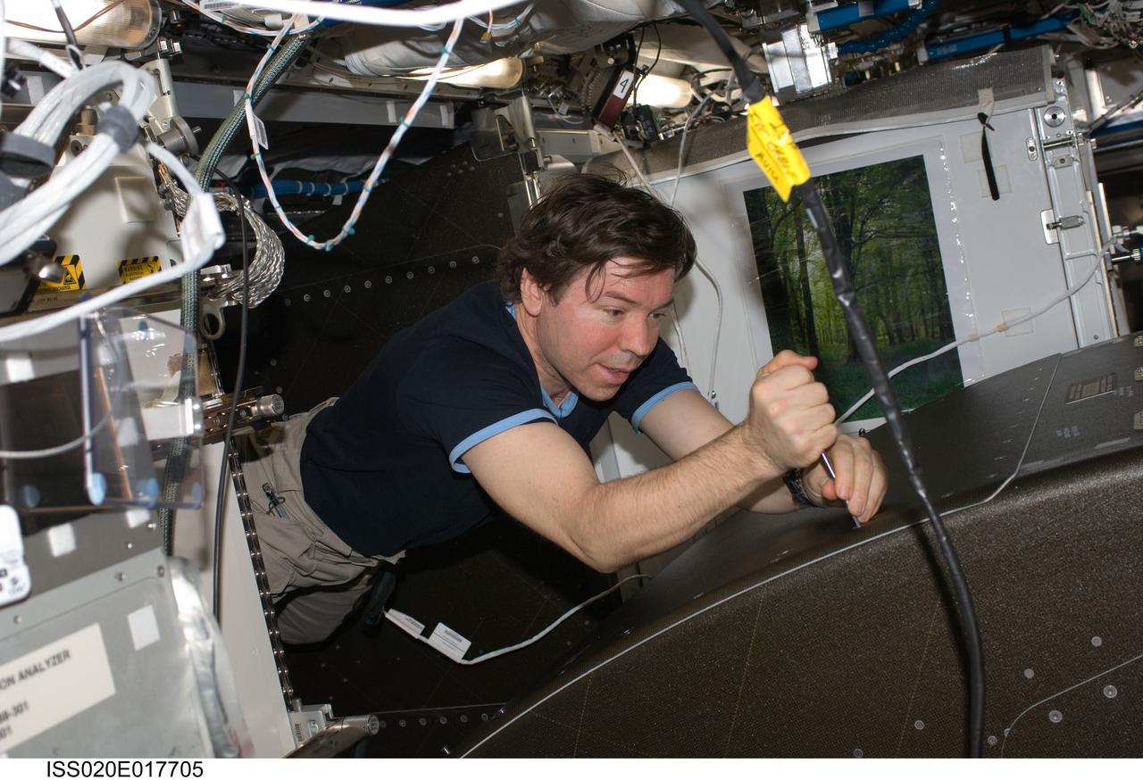
ISS020-E-017705 (7 July 2009) --- NASA astronaut Michael Barratt, Expedition 20 flight engineer, works at a rotated rack in the Destiny laboratory of the International Space Station during in-flight maintenance (IFM) to adjust the periodic flow rate of manual flow control valves for coolant loops.
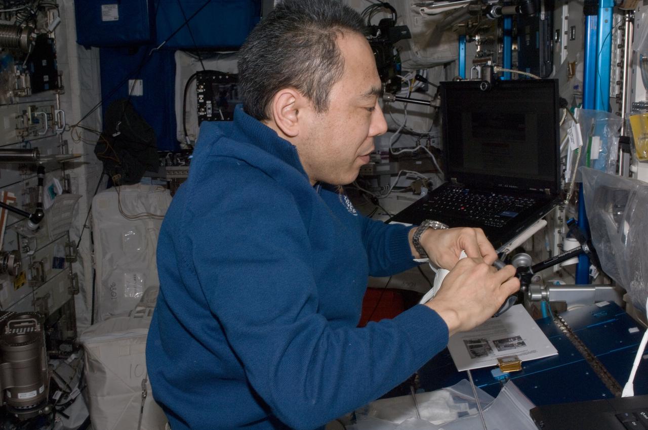
ISS029-E-027334 (14 Oct. 2011) --- In the International Space Station’s Columbus laboratory, Japan Aerospace Exploration Agency astronaut Satoshi Furukawa, Expedition 29 flight engineer, works on Water On/Off Valves (WOOV), performing inspection, cleaning, disinfection and encapsulation on WOOV 3, 4 and 5.
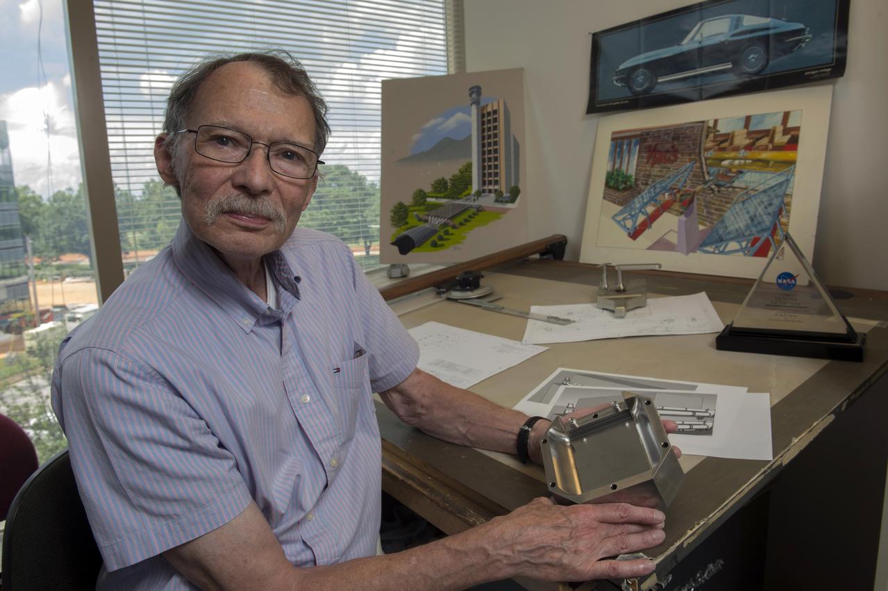
Neill Myers, Marshall’s most patented inventor, demonstrates the Variable-Aperture Reciprocating Reed Valve, an invention that won him his fourth Marshall Invention of the Year award.
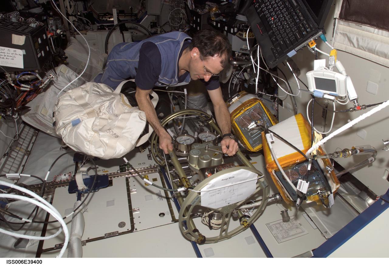
ISS006-E-39400 (17 March 2003) --- Astronaut Donald R. Pettit, Expedition Six NASA ISS science officer, makes a valve adjustment to the Fluid Control Pump Assembly (FCPA), which is a part of the Internal Thermal Control System (ITCS) in the Destiny laboratory on the International Space Station (ISS).
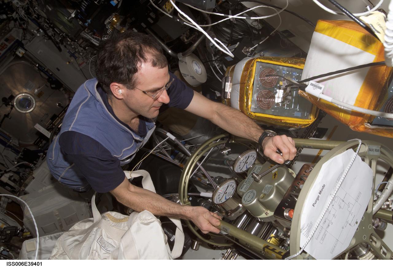
ISS006-E-39401 (17 March 2003) --- Astronaut Donald R. Pettit, Expedition Six NASA ISS science officer, makes a valve adjustment to the Fluid Control Pump Assembly (FCPA), which is a part of the Internal Thermal Control System (ITCS) in the Destiny laboratory on the International Space Station (ISS).
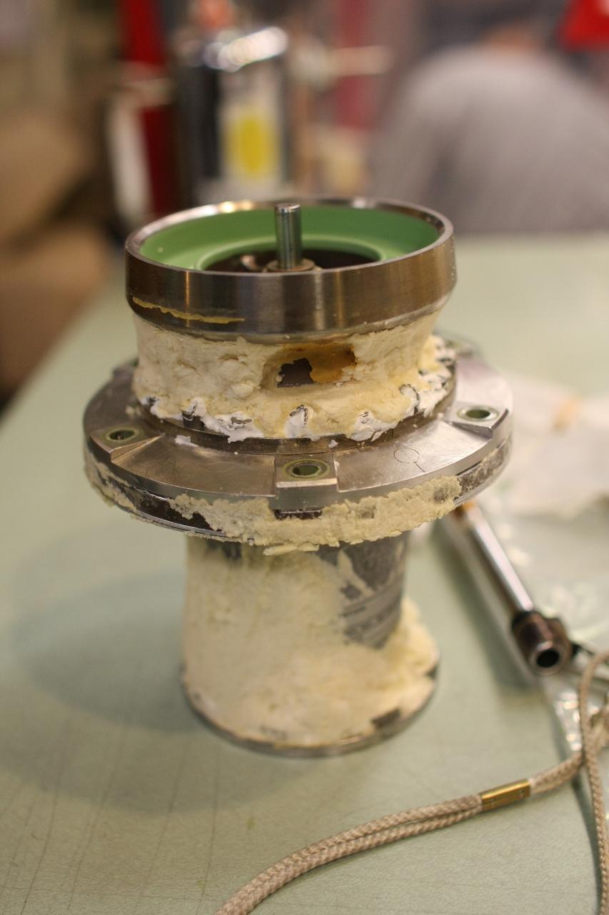
Shown is the disassembly, examination, refurbishment and testing of the LH2 ( liquid hydrogen) and LOX (liquid oxygen) vent and relief valves for the S-IVB-211 engine stage in support of the Constellation/Ares project. This image is extracted from high definition video and is the highest resolution available.
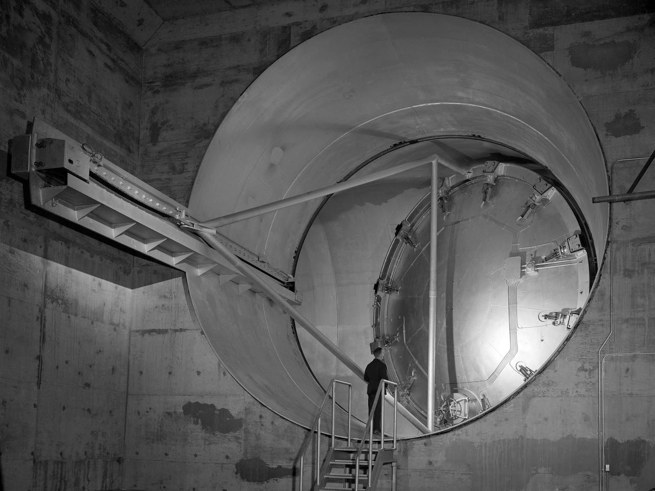
A 24-foot diameter swing valve is seen in an open position inside the new 10- by 10-Foot Supersonic Wind Tunnel at the National Advisory Committee for Aeronautics (NACA) Lewis Flight Propulsion Laboratory. The 10- by 10 was the most powerful propulsion wind tunnel in the nation. After over three years of construction the tunnel was ready to conduct its first tests in early 1956. The 10- by 10-foot tunnel was part of Congress’ Unitary Plan Act which coordinated wind tunnel construction at the NACA, Air Force, industry, and universities. The 10- by 10 was the largest of the three NACA tunnels built under the act. This large swinging valve is critical to the operation of the facility. In one position the valve seals off the tunnel exhaust, making the tunnel a closed circuit, which is used for aerodynamic testing of models. In its other position, the valve acts as a seal across the tunnel and leaves the tunnel exhaust open. This arrangement is used when engines are fired. The air going through the tunnel is taken from the atmosphere and returned to the atmosphere after one pass through the tunnel. Engines up to five feet in diameter can be tested in the 10- by 10-foot test section. Air flows up to Mach 3.5 can be fed through the test section by a 250,000-horsepower axial-flow compressor fan. The incoming air must be dehumidified and cooled so that the proper conditions are present for the test. A large air dryer with 1,890 tons of activated alumina soaks up 1.5 tons of water per minute from the air flow. A cooling apparatus equivalent to 250,000 household air conditioners is used to cool the air.
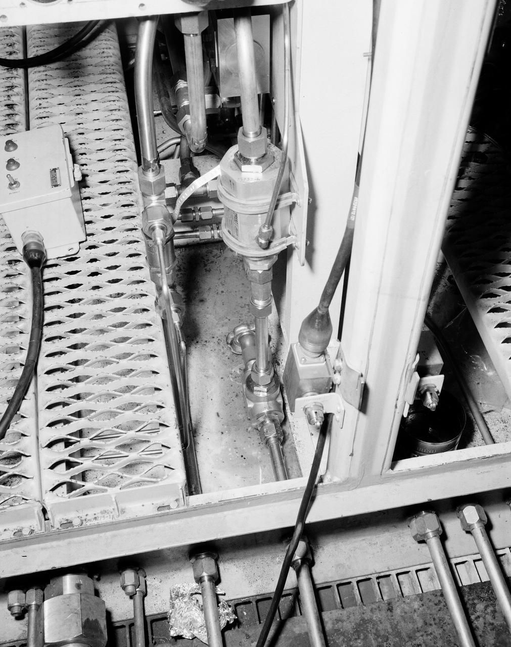
The Marshall Space Flight Center (MSFC) played a crucial role in the development of the huge Saturn rockets that delivered humans to the moon in the 1960s. Many unique facilities existed at MSFC for the development and testing of the Saturn rockets. Affectionately nicknamed “The Arm Farm”, the Random Motion/ Lift-Off Simulator was one of those unique facilities. This facility was developed to test the swing arm mechanisms that were used to hold the rocket in position until liftoff. The Arm Farm provided the capability of testing the detachment and reconnection of various arms under brutally realistic conditions. The 18-acre facility consisted of more than a half dozen arm test positions and one position for testing access arms used by the Apollo astronauts. Each test position had two elements: a vehicle simulator for duplicating motions during countdown and launch; and a section duplicating the launch tower. The vehicle simulator duplicated the portion of the vehicle skin that contained the umbilical connections and personnel access hatches. Driven by a hydraulic servo system, the vehicle simulator produced relative motion between the vehicle and tower. On the Arm Farm, extreme environmental conditions (such as a launch scrub during an approaching Florida thunderstorm) could be simulated. The dramatic scenes that the Marshall engineers and technicians created at the Arm Farm permitted the gathering of crucial technical and engineering data to ensure a successful real time launch from the Kennedy Space Center. This photo depicts a close up view of the S-IV-B aft swing arm hydraulic with drain system orifice valve.
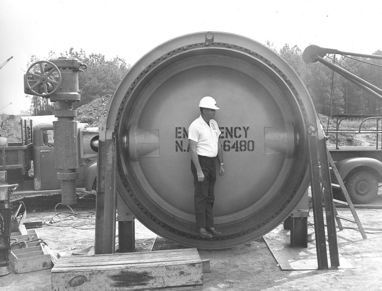
At its founding, the Marshall Space Flight Center (MSFC) inherited the Army’s Jupiter and Redstone test stands, but much larger facilities were needed for the giant stages of the Saturn V. From 1960 to 1964, the existing stands were remodeled and a sizable new test area was developed. The new comprehensive test complex for propulsion and structural dynamics was unique within the nation and the free world, and they remain so today because they were constructed with foresight to meet the future as well as on going needs. Construction of the S-IC Static test stand complex began in 1961 in the west test area of MSFC, and was completed in 1964. The S-IC static test stand was designed to develop and test the 138-ft long and 33-ft diameter Saturn V S-IC first stage, or booster stage, weighing in at 280,000 pounds. Required to hold down the brute force of a 7,500,000-pound thrust produced by 5 F-1 engines, the S-IC static test stand was designed and constructed with the strength of hundreds of tons of steel and 12,000,000 pounds of cement, planted down to bedrock 40 feet below ground level. The foundation walls, constructed with concrete and steel, are 4 feet thick. The base structure consists of four towers with 40-foot-thick walls extending upward 144 feet above ground level. The structure was topped by a crane with a 135-foot boom. With the boom in the upright position, the stand was given an overall height of 405 feet, placing it among the highest structures in Alabama at the time. In addition to the stand itself, related facilities were constructed during this time. Built northeast of the stand was a newly constructed Pump House. Its function was to provide water to the stand to prevent melting damage during testing. The water was sprayed through small holes in the stand’s 1900 ton flame deflector at the rate of 320,000 gallons per minute. In this photograph, a construction worker demonstrates the size of the massive water valve that was used in the testing cooling process.
ISS037-E-021962 (28 Oct. 2013) --- NASA astronaut Michael Hopkins, Expedition 37 flight engineer, performs routine in-flight maintenance within the Carbon Dioxide Removal Assembly in the International Space Station?s Tranquility node. This device removes carbon dioxide from the station?s atmosphere and is part of the station?s Environmental Control and Life Support System that provides clean water and air to the crew.

TEST SETUP FOR SHUTTER VALVE FLOW TEST
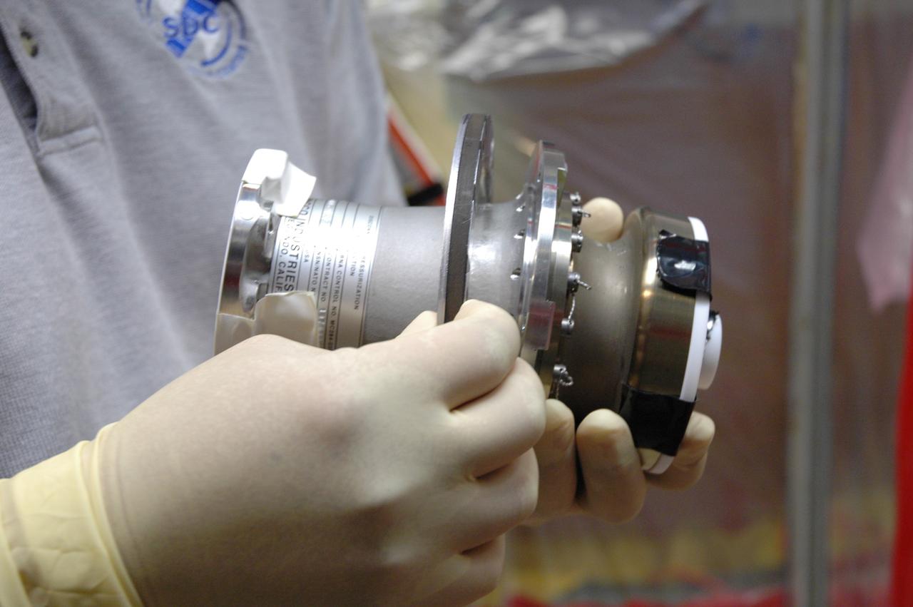
MAGNETOSTRICTIVE VALVE ASSEMBLY SMALL BUSINESS INNOVATIVE RESEARCH PROGRAM - MAROTTA INC.
Vibration test of the Orion Service Module advanced development propellant isolation valve. "X: Angle of Rotation".
N-206 12ft W.T. ADTE Project (Aeronautics Design and Test Environment) Old TPC valve actuators

Vibration test of the Orion Service Module advanced development propellant isolation valve. "X: Angle of Rotation".
N-206 12ft W.T. ADTE Project (Aeronautics Design and Test Environment) New piping to old valves
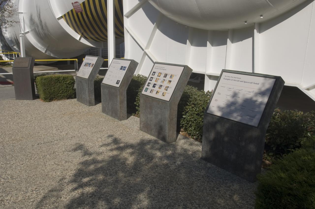
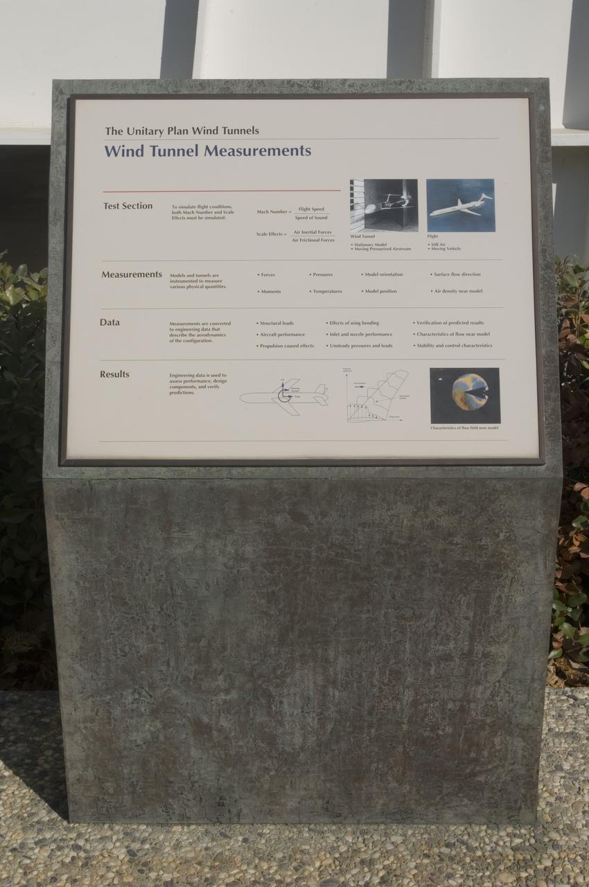
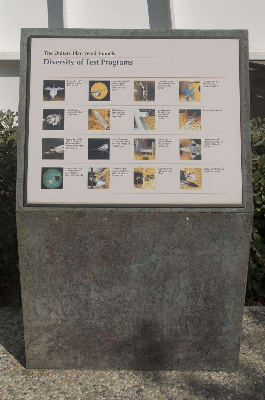
Ames and Moffett Field (MFA) historical sites and memorials Unitary Plan Wind Tunned plaza; display and historical site plaques with the NASA logo on the Wind Tunnel valve as a backdrop.
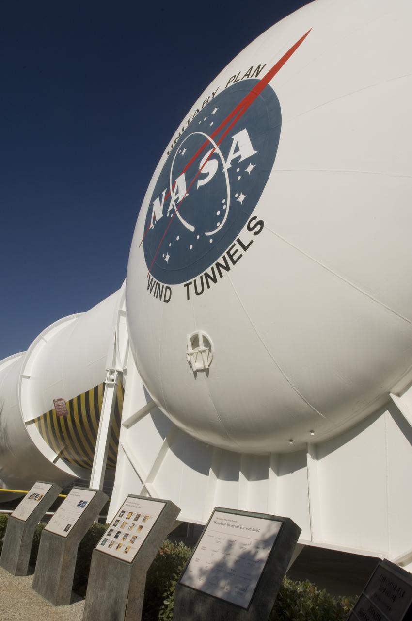
Ames and Moffett Field (MFA) historical sites and memorials Unitary Plan Wind Tunned plaza; display and historical site plaques with the NASA logo on the Wind Tunnel valve as a backdrop.
Ames and Moffett Field (MFA) historical sites and memorials Unitary Plan Wind Tunned plaza; display and historical site plaques with the NASA logo on the Wind Tunnel valve as a backdrop.
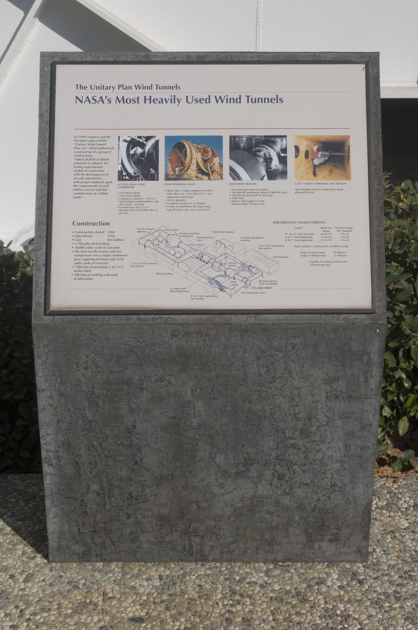
Ames and Moffett Field (MFA) historical sites and memorials Unitary Plan Wind Tunned plaza; display and historical site plaques with the NASA logo on the Wind Tunnel valve as a backdrop.
ISS033-E-007246 (24 Sept. 2012) --- Japan Aerospace Exploration Agency astronaut Aki Hoshide, Expedition 33 flight engineer, works on replacing valves in an International Space Station’s Carbon Dioxide Removal Assembly.

Ames and Moffett Field (MFA) historical sites and memorials Unitary Plan Wind Tunned plaza; display and historical site plaques with the NASA logo on the Wind Tunnel valve as a backdrop.
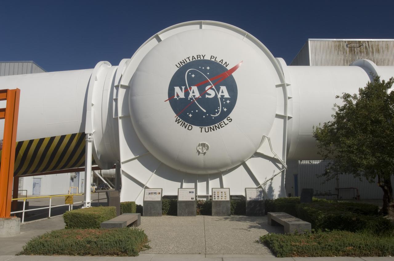
Ames and Moffett Field (MFA) historical sites and memorials Unitary Plan Wind Tunned plaza; display and historical site plaques with the NASA logo on the Wind Tunnel valve as a backdrop.
Ames and Moffett Field (MFA) historical sites and memorials Unitary Plan Wind Tunned plaza; display and historical site plaques with the NASA logo on the Wind Tunnel valve as a backdrop.
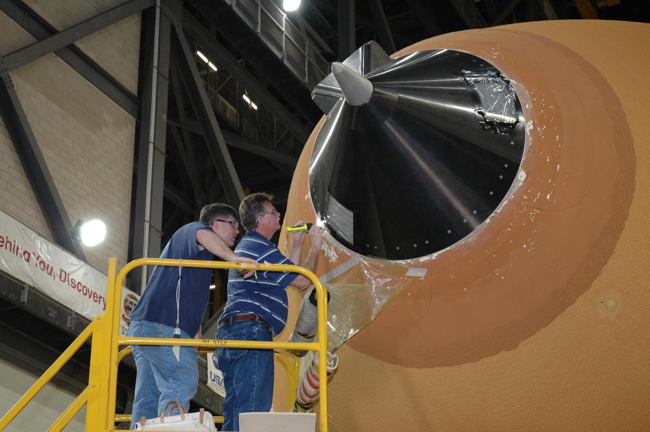
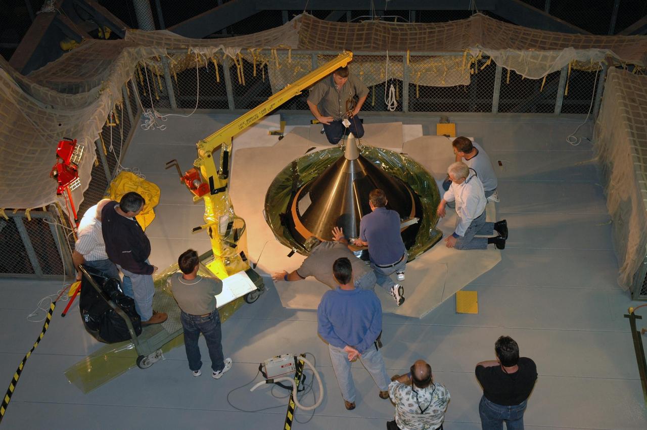
KENNEDY SPACE CENTER, FLA. - In the transfer aisle of the Vehicle Assembly Building, workers work on the rim around the nose cap of external tank number 119, the tank designated for mission STS-121. The cap was removed in order to install a new gaseous oxygen vent valve underneath. Vapors are created prior to launch as the liquid oxygen in the external tank boils off. At the forward end of each external tank propellant tank is a vent and relief valve that can be opened before launch for venting or by excessive tank pressure for relief. The vent function is available only before launch. Mission STS-121 to the International Space Station is scheduled for launch in July. Photo credit: NASA/Jim Grossmann
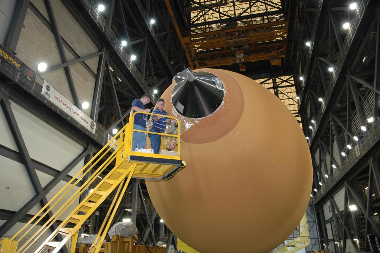
KENNEDY SPACE CENTER, FLA. - In the Vehicle Assembly Building at NASA's Kennedy Space Center, the nose cap on top of external tank number 119 has been removed. A new gaseous oxygen vent valve will be installed. Tank 119 is designated for mission STS-121. Vapors are created prior to launch as the liquid oxygen in the external tank boils off. At the forward end of each external tank propellant tank is a vent and relief valve that can be opened before launch for venting or by excessive tank pressure for relief. The vent function is available only before launch. Mission STS-121 to the International Space Station is scheduled for launch in July. Photo credit: NASA/Jim Grossmann
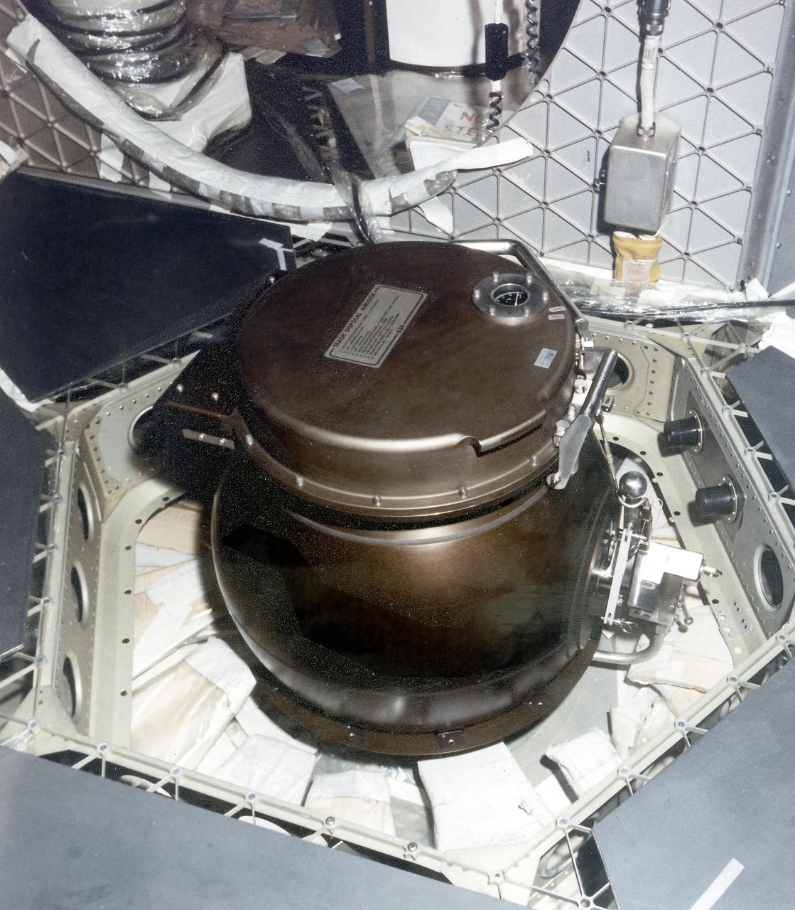
This is a close-up photograph of the Orbital Workshop (OWS) trash disposal airlock located on the floor of the lower level of the OWS. It provided a means of passing trash from the pressurized habitable area into the unpressurized waste tank. The crewman opened a valve which brought the airlock to the same pressure as that within the workshop. He then opened the lid, placed the bagged trash inside, closed the lid and locked it. By turning the valve handle, he reduced the pressure within the airlock until it reached the vacuum of the waste tank. The crewman then operated an ejector handle that caused a scissors-type mechanism to push the bagged trash from the airlock into the tank.
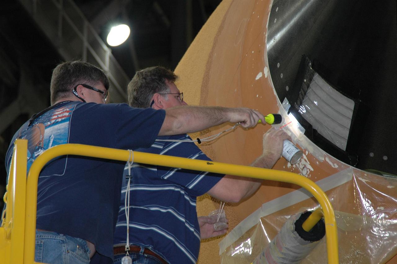
KENNEDY SPACE CENTER, FLA. - In the transfer aisle of the Vehicle Assembly Building, workers check the rim around the nose cap of external tank number 119, the tank designated for mission STS-121. The cap was removed in order to install a new gaseous oxygen vent valve underneath. Vapors are created prior to launch as the liquid oxygen in the external tank boils off. At the forward end of each external tank propellant tank is a vent and relief valve that can be opened before launch for venting or by excessive tank pressure for relief. The vent function is available only before launch. Mission STS-121 to the International Space Station is scheduled for launch in July. Photo credit: NASA/Jim Grossmann
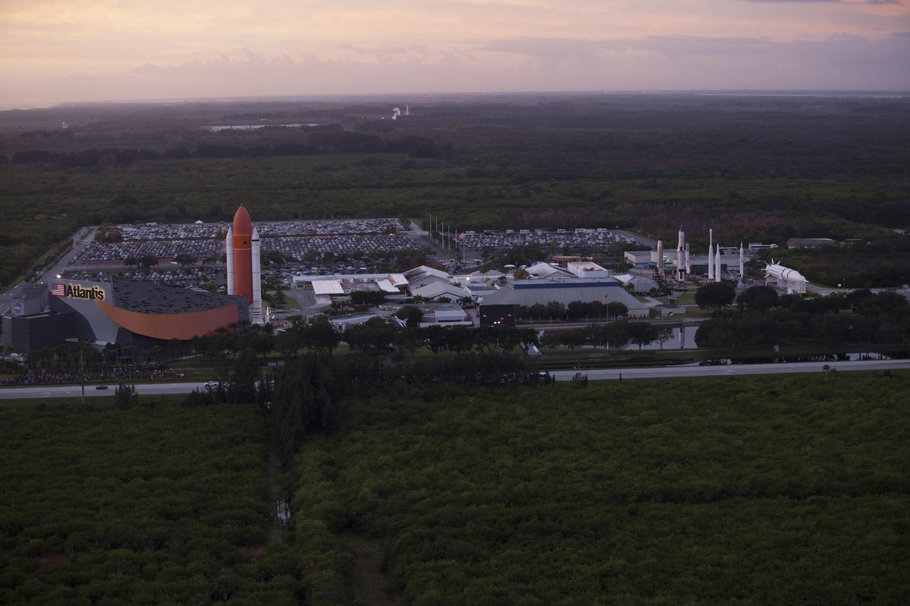
This helicopter view of the Kennedy Space Center Visitor Complex shows the thousands of vehicles parked where guests gather to see the launch of the Orion Flight Test. The liftoff was postponed because of an issue related to fill and drain valves on the Delta IV Heavy rocket that teams could not troubleshoot by the time the launch window expired.
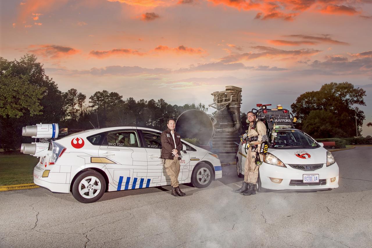
Andrew Denio, a Marshall information technology specialist in the Office of the Chief Information Officer, and Judson Hudson, a lab technician and computer-aided designer in Marshall’s Valve & Component Laboratory, show off their Ghostbusters and Star Wars themed vehicles in front of MSFC building 4200, for Halloween 2019.
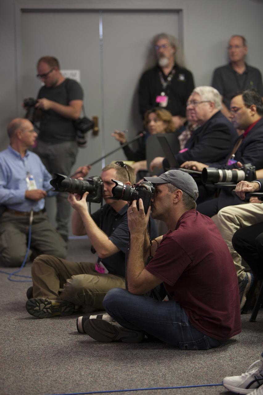
In the Kennedy Space Center’s Press Site auditorium, news media representatives listen and take photographs as NASA and industry leaders talk about the postponement of the Orion Flight Test launch due to an issue related to fill and drain valves on the Delta IV Heavy rocket.
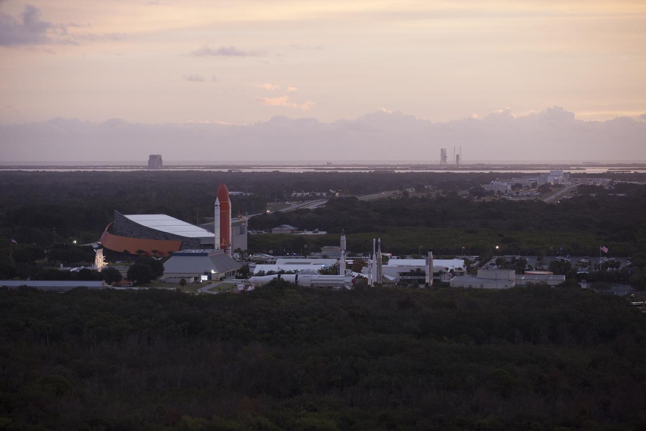
This helicopter view of the Kennedy Space Center Visitor Complex shows the thousands of vehicles parked where guests gather to see the launch of the Orion Flight Test. The liftoff was postponed because of an issue related to fill and drain valves on the Delta IV Heavy rocket that teams could not troubleshoot by the time the launch window expired.
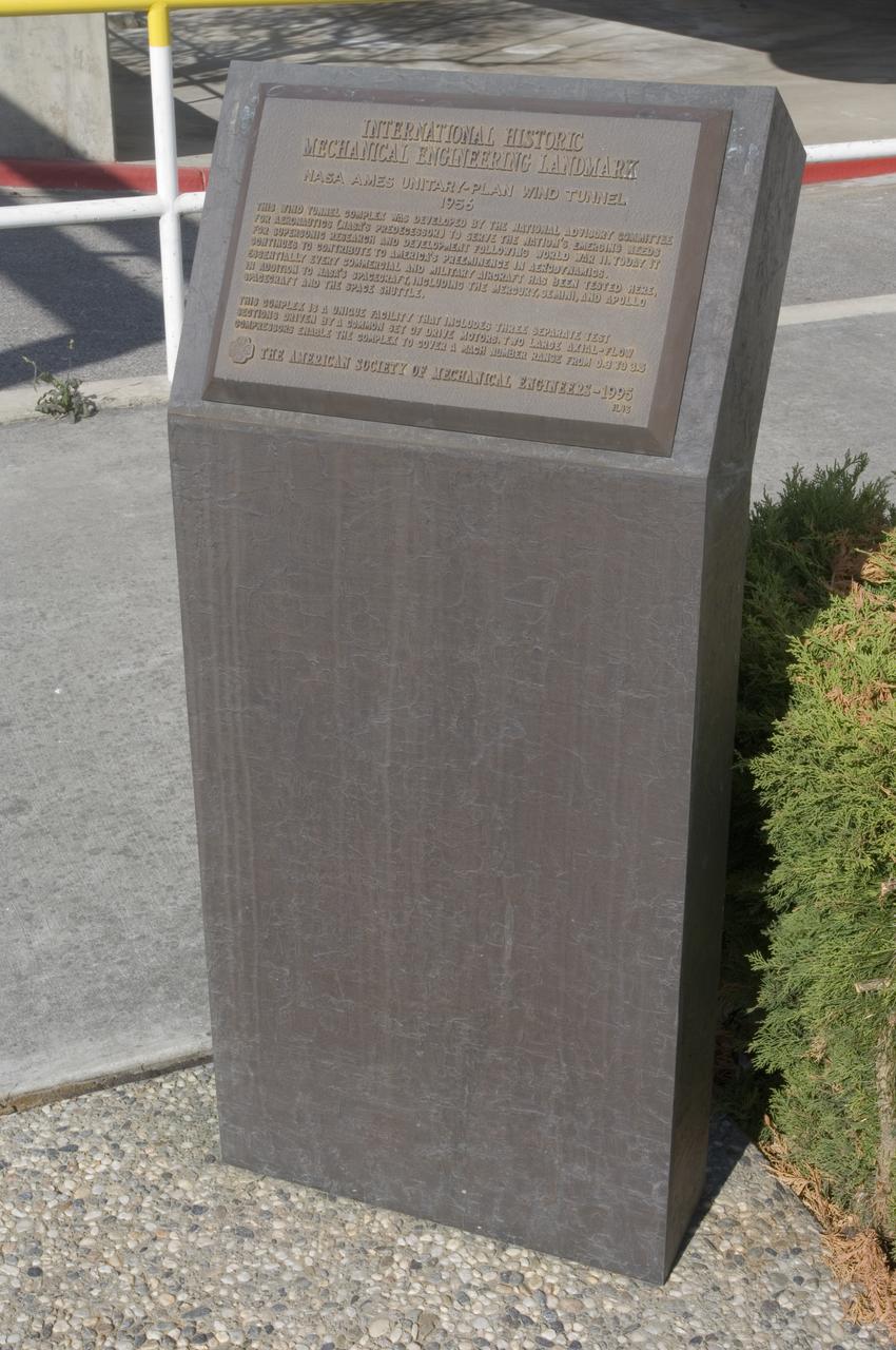
Ames and Moffett Field (MFA) historical sites and memorials Unitary Plan Wind Tunned plaza; display and historical site plaques with the NASA logo on the Wind Tunnel valve as a backdrop. shown is the Unitary International Historic Mechanical Engineering Landmark Dedication plaque (American Society of Mechanical Engineers) May 5, 1995
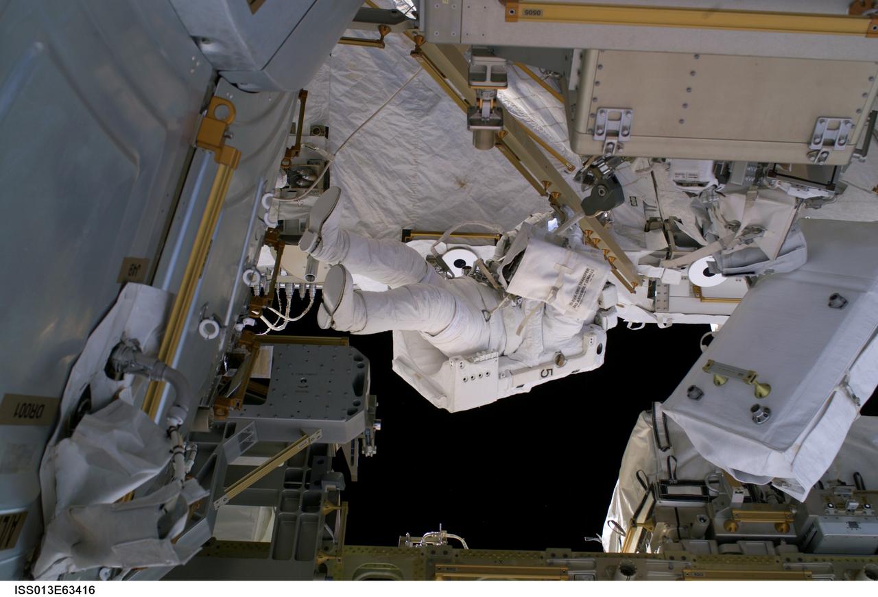
ISS013-E-63416 (3 August 2006) --- Astronaut Thomas Reiter, who represents the European Space Agency on the Expedition 13 crew, translates near a targeted vent valve on the Destiny laboratory of the International Space during a 5-hour, 54-minute spacewalk.
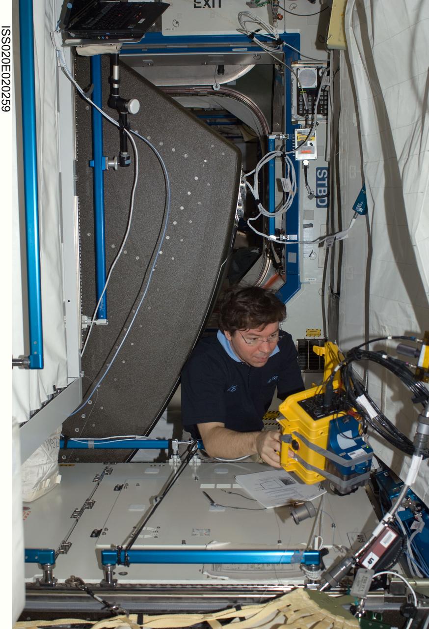
ISS020-E-020259 (8 July 2009) --- NASA astronaut Michael Barratt, Expedition 20 flight engineer, works at a rotated rack in the Destiny laboratory of the International Space Station during in-flight maintenance (IFM) to adjust the periodic flow rate of manual flow control valves for coolant loops.
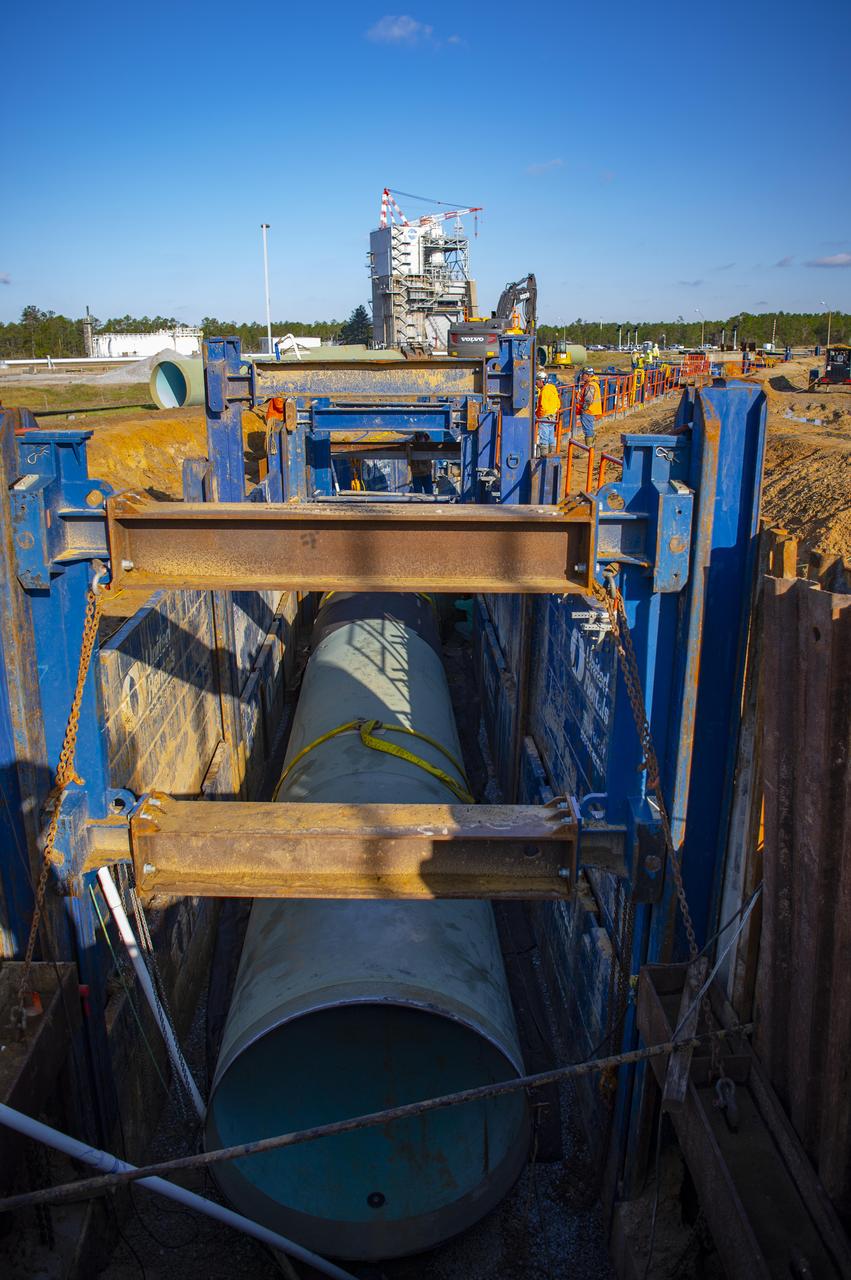
In this March 2022 photo, crews use a shoring system to hold back soil as they install new 75-inch piping leading from the NASA Stennis High Pressure Industrial Water Facility to the valve vault pit serving the Fred Haise Test Stand.
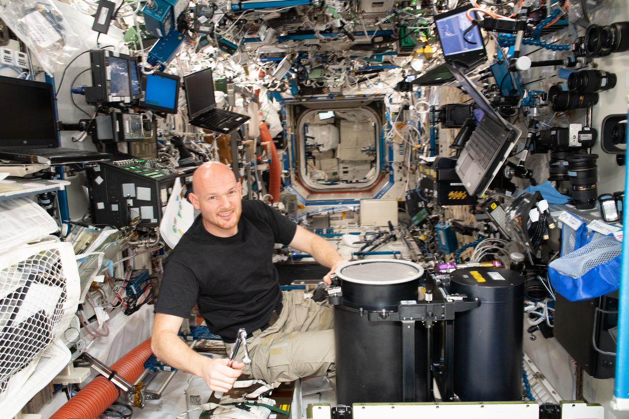
iss056e033076 (June 25, 2018) --- Astronaut Alexander Gerst of ESA (European Space Agency) works on life support maintenance inside the International Space Station's Destiny laboratory module. Gerst was removing and replacing valves inside the Carbon Dioxide Removal Assembly.
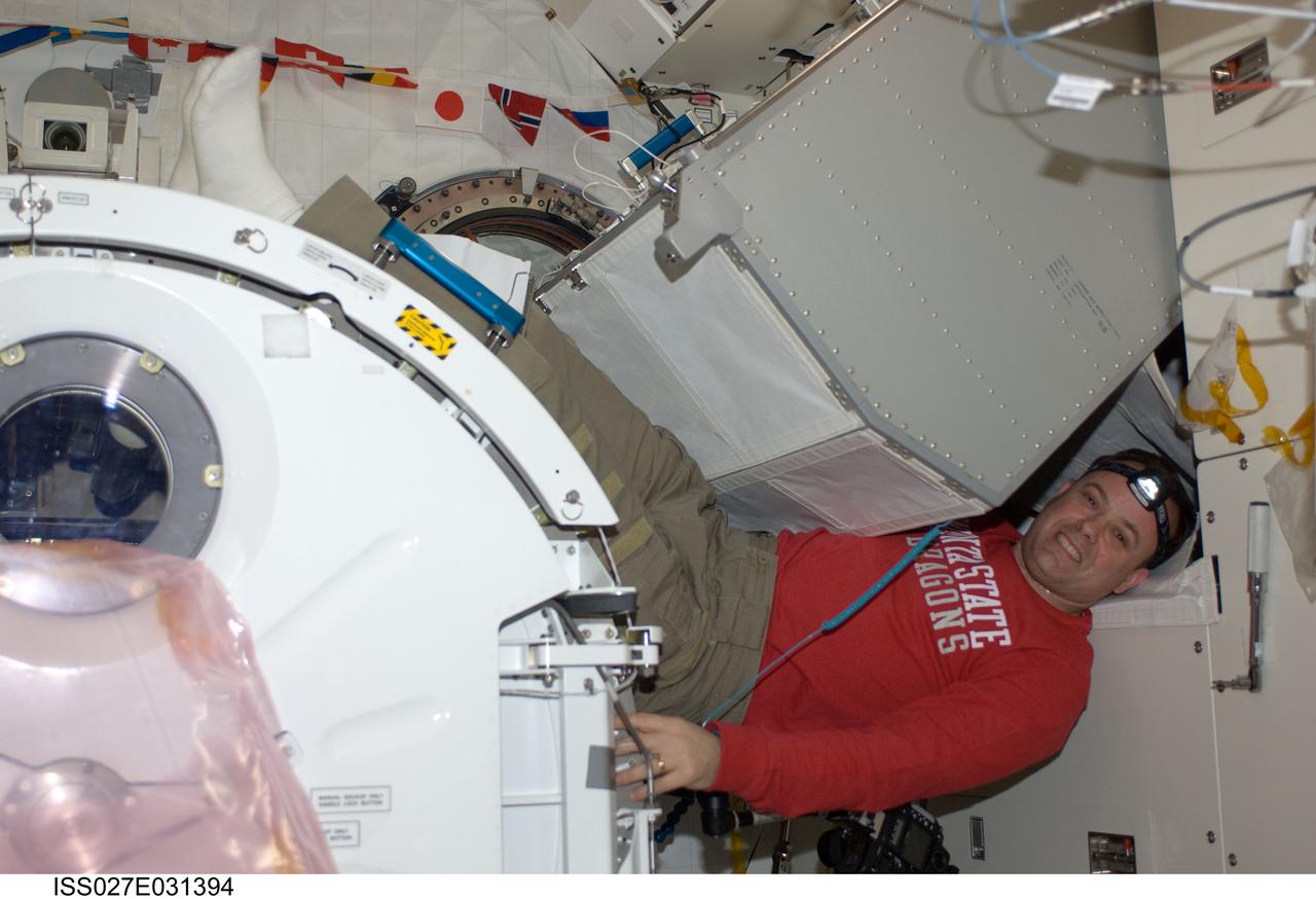
ISS027-E-031394 (16 May 2011) --- NASA astronaut Ron Garan, Expedition 27 flight engineer, installs a helium valve unit at the Common Gas Supply Equipment (CGSE) rack in the Kibo laboratory of the International Space Station.
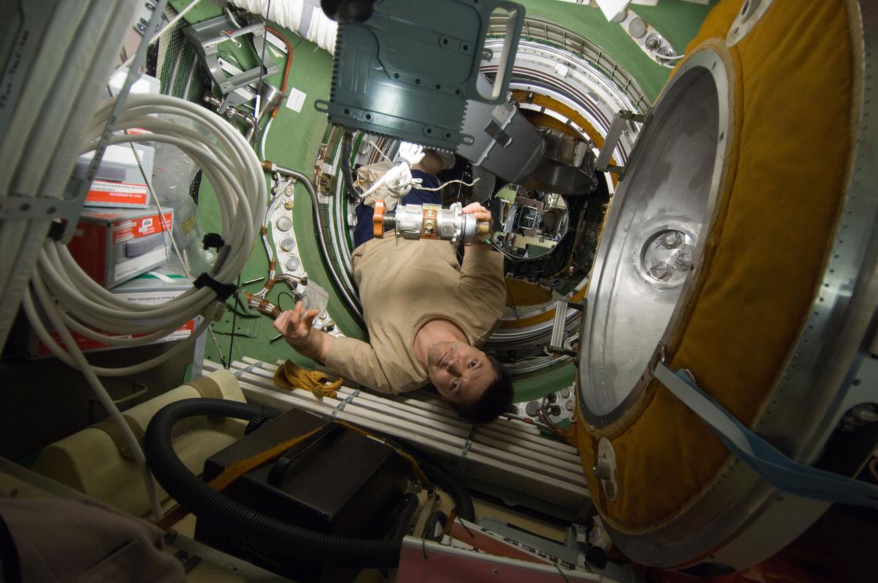
ISS030-E-177117 (12 March 2012) --- Russian cosmonaut Oleg Kononenko, Expedition 30 flight engineer, performs removal and replacement of the KVD Pressure Equalization Valve (PEV) in the transfer compartment between the Zarya Functional Cargo Block (FGB) and the Zvezda Service Module of the International Space Station.
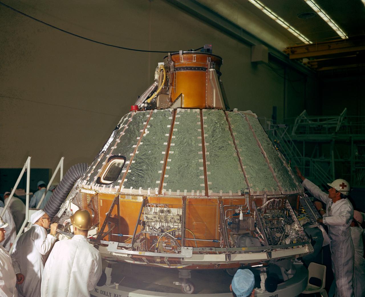
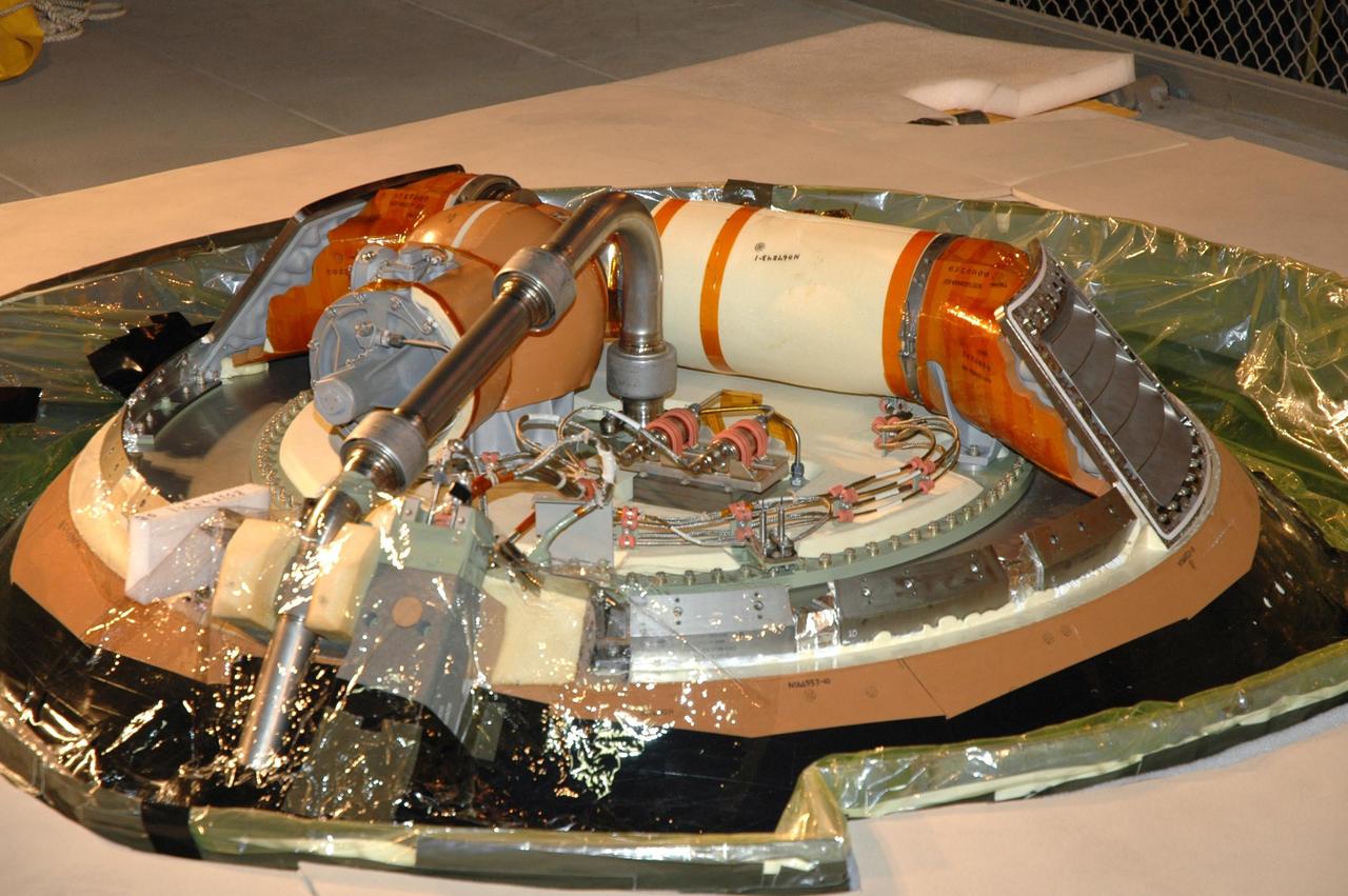
S66-41852 (1966) --- Spacecraft 012 looking toward -Y axis during installation of heat shield. Note uprighting system compressor in aft bay, at right, and Reaction Control System (RCS) valve module panel, center of photo.
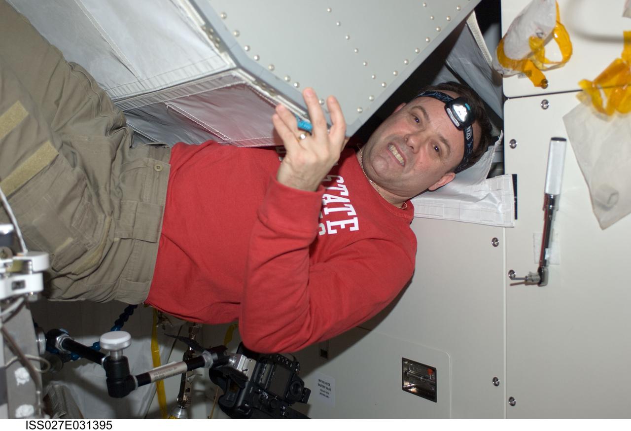
ISS027-E-031395 (16 May 2011) --- NASA astronaut Ron Garan, Expedition 27 flight engineer, installs a helium valve unit at the Common Gas Supply Equipment (CGSE) rack in the Kibo laboratory of the International Space Station.
In the Kennedy Space Center’s Press Site auditorium, Dan Collins, United Launch Alliance chief operating officer spoke to members of the news media about the postponement of the Orion Flight Test launch due to an issue related to fill and drain valves on the Delta IV Heavy rocket.
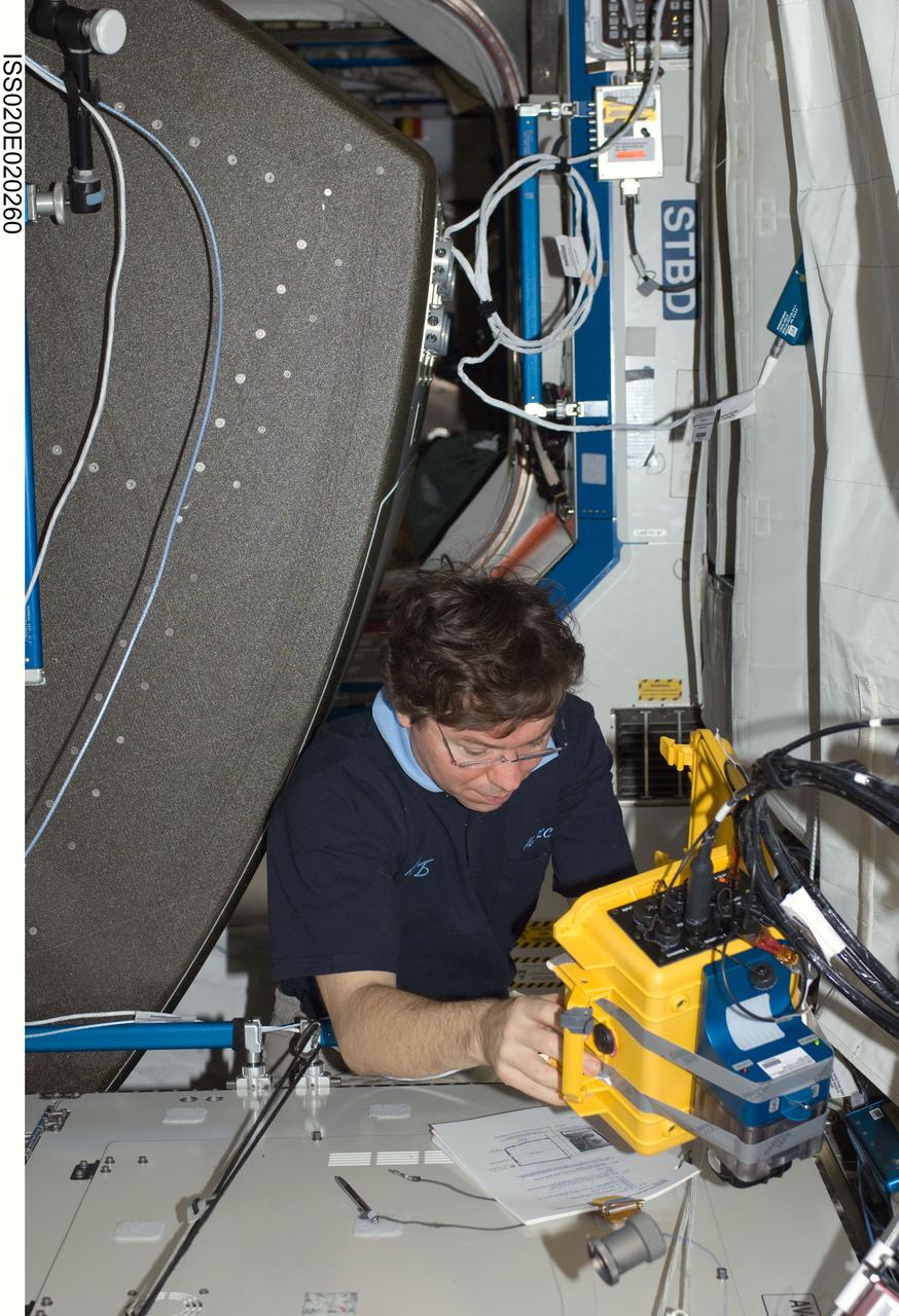
ISS020-E-020260 (8 July 2009) --- NASA astronaut Michael Barratt, Expedition 20 flight engineer, works at a rotated rack in the Destiny laboratory of the International Space Station during in-flight maintenance (IFM) to adjust the periodic flow rate of manual flow control valves for coolant loops.
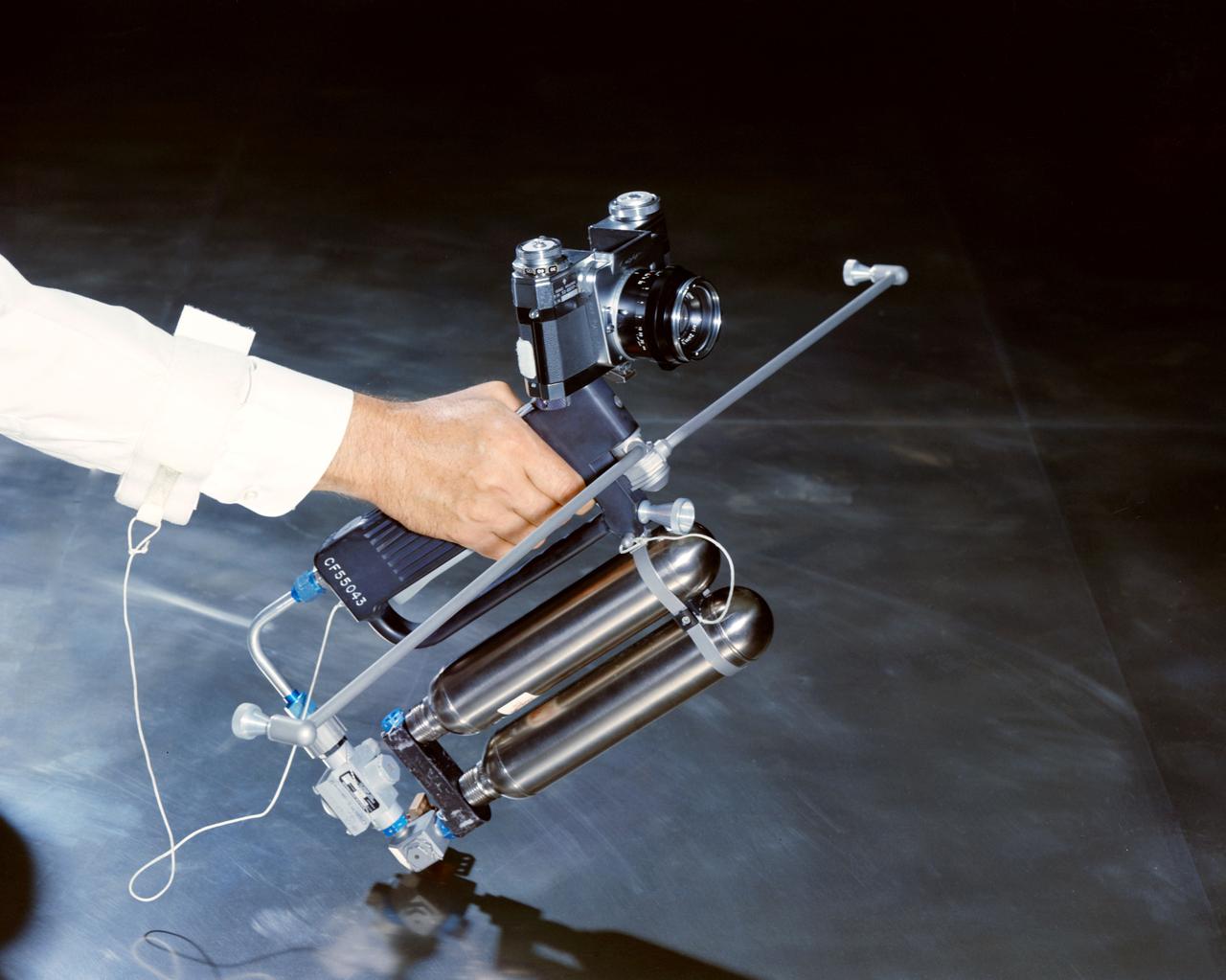
Hand-Held Self-Maneuvering Unit to be used during extravehicular activity (EVA) on Gemini 4 flight. It is an integral unit that contains its own high pressure metering valves and nozzles required to produce controlled thrust. A camera is mounted on the front of the unit.
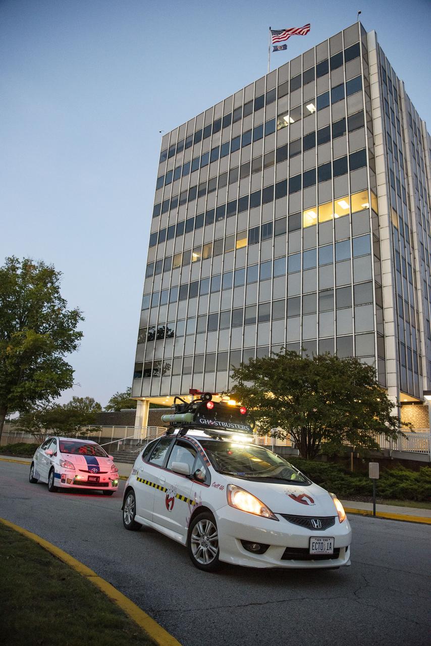
Andrew Denio, a Marshall information technology specialist in the Office of the Chief Information Officer, and Judson Hudson, a lab technician and computer-aided designer in Marshall’s Valve & Component Laboratory, show off their Ghostbusters and Star Wars themed vehicles in front of MSFC building 4200, for Halloween 2019.
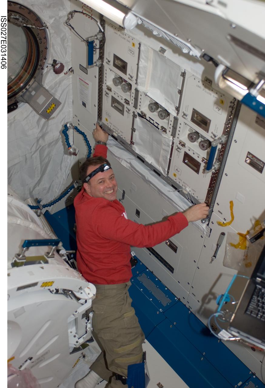
ISS027-E-031406 (16 May 2011) --- NASA astronaut Ron Garan, Expedition 27 flight engineer, installs a helium valve unit at the Common Gas Supply Equipment (CGSE) rack in the Kibo laboratory of the International Space Station.
ISS034-E-031766 (18 Jan. 2013) --- Canadian Space Agency astronaut Chris Hadfield, Expedition 34 flight engineer, removes the Water Temporary Substitution Manifold (WTSM) and installs the Water On-Off Valve (WOOV) in the Columbus laboratory of the International Space Station.
ISS034-E-031578 (18 Jan. 2013) --- Canadian Space Agency astronaut Chris Hadfield, Expedition 34 flight engineer, removes the Water Temporary Substitution Manifold (WTSM) and installs the Water On-Off Valve (WOOV) in the Columbus laboratory of the International Space Station.
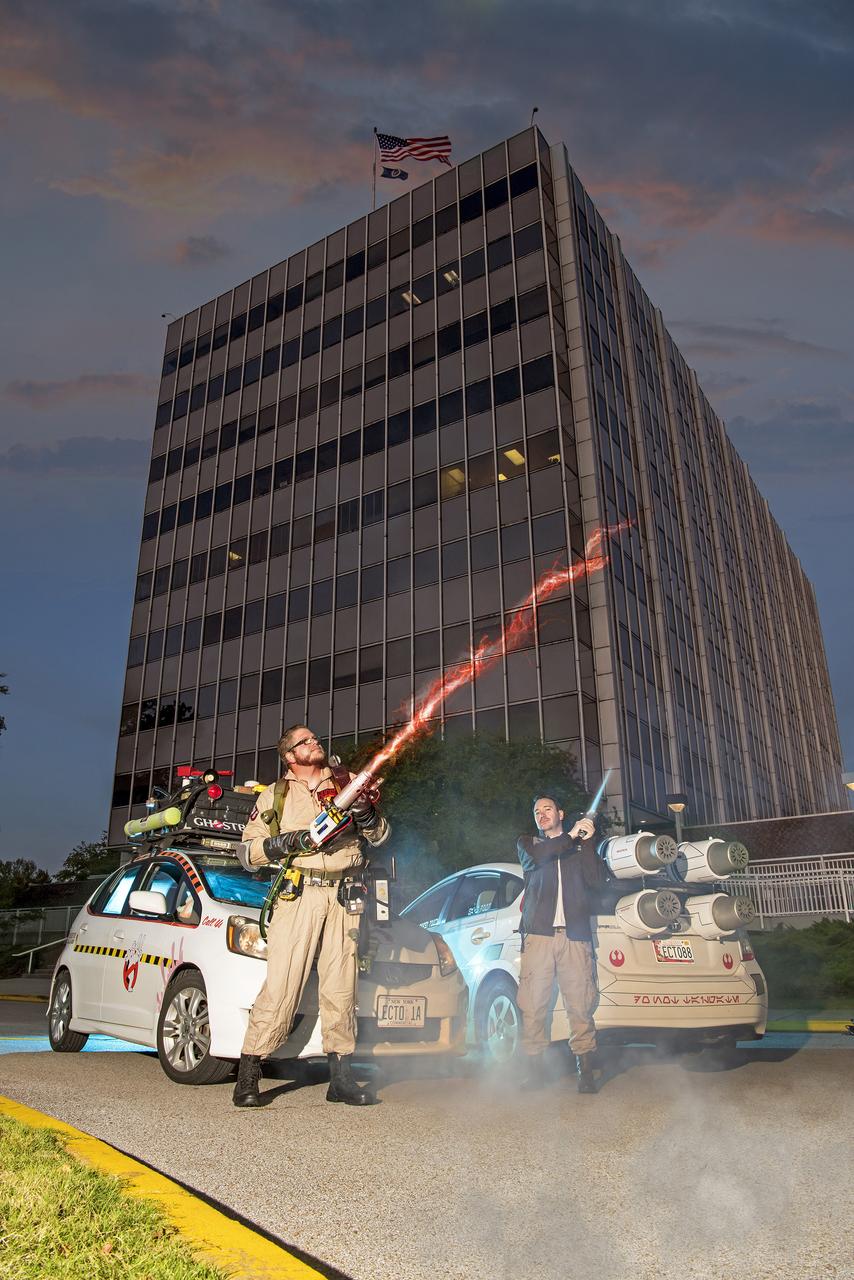
Andrew Denio, a Marshall information technology specialist in the Office of the Chief Information Officer, and Judson Hudson, a lab technician and computer-aided designer in Marshall’s Valve & Component Laboratory, show off their Ghostbusters and Star Wars themed vehicles in front of MSFC building 4200, for Halloween 2019.
CAPE CANAVERAL, Fla. – A close up view of the valve removed from Atlantis’ external tank inside the Vehicle Assembly Building at NASA’s Kennedy Space Center. Technicians removed the valve after small dings were found on the sealing surface of the quick disconnect system that handles liquid-hydrogen fuel for the shuttle’s three main engines. The tank will be attached to the twin solid rocket boosters on Aug. 3 for the STS-125 mission, the fifth and final shuttle servicing mission to NASA’s Hubble Space Telescope. During the mission, the crew will install new instruments on the telescope, including the Cosmic Origins Spectrograph and the Wide Field Camera 3. A refurbished Fine Guidance Sensor will replace one unit of three now onboard. Mission specialists will also install new gyroscopes, batteries and thermal blankets on the telescope. Launch is targeted for Oct. 8. Photo credit: NASA/Dimitri Gerondidakis
CAPE CANAVERAL, Fla. – Inside the Vehicle Assembly Building at NASA's Kennedy Space Center, a technician holds the replacement valve for Atlantis’ external tank. Technicians removed an old valve after small dings were found on the sealing surface of the quick disconnect system that handles liquid-hydrogen fuel for the shuttle’s three main engines. The tank will be attached to the twin solid rocket boosters on Aug. 3 for the STS-125 mission, the fifth and final shuttle servicing mission to NASA’s Hubble Space Telescope. During the mission, the crew will install new instruments on the telescope, including the Cosmic Origins Spectrograph and the Wide Field Camera 3. A refurbished Fine Guidance Sensor will replace one unit of three now onboard. Mission specialists will also install new gyroscopes, batteries and thermal blankets on the telescope. Launch is targeted for Oct. 8. Photo credit: NASA/Jim Grossmann

CAPE CANAVERAL, Fla. – A close up view of the valve removed from Atlantis’ external tank inside the Vehicle Assembly Building at NASA’s Kennedy Space Center. Technicians removed the valve after small dings were found on the sealing surface of the quick disconnect system that handles liquid-hydrogen fuel for the shuttle’s three main engines. The tank will be attached to the twin solid rocket boosters on Aug. 3 for the STS-125 mission, the fifth and final shuttle servicing mission to NASA’s Hubble Space Telescope. During the mission, the crew will install new instruments on the telescope, including the Cosmic Origins Spectrograph and the Wide Field Camera 3. A refurbished Fine Guidance Sensor will replace one unit of three now onboard. Mission specialists will also install new gyroscopes, batteries and thermal blankets on the telescope. Launch is targeted for Oct. 8. Photo credit: NASA/Dimitri Gerondidakis
KENNEDY SPACE CENTER, FLA. - In the transfer aisle of the Vehicle Assembly Building, workers get ready to ablate the rim around the nose cap of external tank number 119, the tank designated for mission STS-121. The cap was removed in order to install a new gaseous oxygen vent valve underneath. Vapors are created prior to launch as the liquid oxygen in the external tank boils off. At the forward end of each external tank propellant tank is a vent and relief valve that can be opened before launch for venting or by excessive tank pressure for relief. The vent function is available only before launch. Mission STS-121 to the International Space Station is scheduled for launch in July. Photo credit: NASA/Jim Grossmann
KENNEDY SPACE CENTER, FLA. - In the Vehicle Assembly Building at NASA's Kennedy Space Center, workers begin removal of the nose cap on top of external tank number 119, the tank designated for mission STS-121. The cap is being removed in order to install a new gaseous oxygen vent valve under the nose cap. Vapors are created prior to launch as the liquid oxygen in the external tank boils off. At the forward end of each external tank propellant tank is a vent and relief valve that can be opened before launch for venting or by excessive tank pressure for relief. The vent function is available only before launch. Mission STS-121 to the International Space Station is scheduled for launch in July. Photo credit: NASA/Jim Grossmann
CAPE CANAVERAL, Fla. – Inside the Vehicle Assembly Building at NASA's Kennedy Space Center, a technician holds the replacement valve for Atlantis’ external tank. Technicians removed an old valve after small dings were found on the sealing surface of the quick disconnect system that handles liquid-hydrogen fuel for the shuttle’s three main engines. The tank will be attached to the twin solid rocket boosters on Aug. 3 for the STS-125 mission, the fifth and final shuttle servicing mission to NASA’s Hubble Space Telescope. During the mission, the crew will install new instruments on the telescope, including the Cosmic Origins Spectrograph and the Wide Field Camera 3. A refurbished Fine Guidance Sensor will replace one unit of three now onboard. Mission specialists will also install new gyroscopes, batteries and thermal blankets on the telescope. Launch is targeted for Oct. 8. Photo credit: NASA/Jim Grossmann

KENNEDY SPACE CENTER, FLA. - In the Vehicle Assembly Building at NASA's Kennedy Space Center, workers remove the nose cap on top of external tank number 119, the tank designated for mission STS-121. The cap is being removed in order to install a new gaseous oxygen vent valve under the nose cap. Vapors are created prior to launch as the liquid oxygen in the external tank boils off. At the forward end of each external tank propellant tank is a vent and relief valve that can be opened before launch for venting or by excessive tank pressure for relief. The vent function is available only before launch. Mission STS-121 to the International Space Station is scheduled for launch in July. Photo credit: NASA/Jim Grossmann
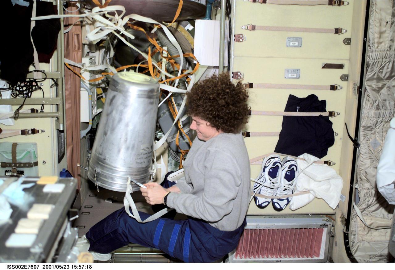
ISS002-E-7607 (23 May 2001) --- Susan J. Helms, Expedition Two flight engineer, works with a strap on a water container in the Zvezda Service Module. The image was taken with a digital still camera.
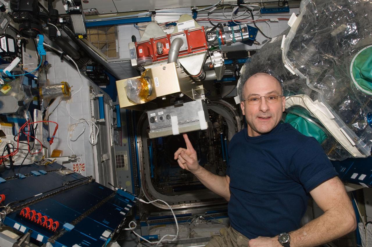
ISS031-E-096083 (8 June 2012) --- NASA astronaut Don Pettit, Expedition 31 flight engineer, poses for a photo with the Amine Swingbed Power Handler Unit during scheduled in-flight maintenance in the Harmony node of the International Space Station.
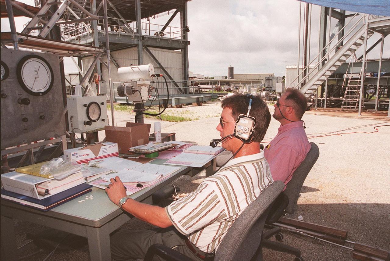
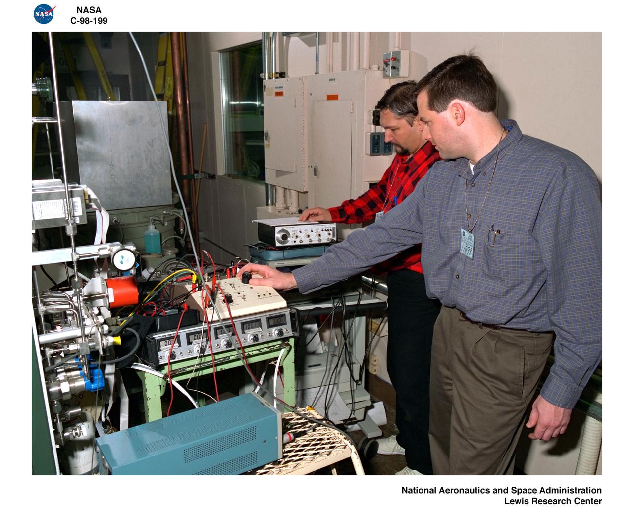
At the Launch Equipment Test Facility, Mike Ynclan, with Dynacs, and Greg Melton, a NASA engineer, look at measurements during testing of the X-33 umbilical system. A team of Kennedy Space Center experts developed the umbilical system, comprising panels, valves and hoses that provide the means to load the X-33 with super-cold propellant. The X-33, under construction at Lockheed Martin Skunk Works in Palmdale, Calif., is a half-scale prototype of the planned operational reusable launch vehicle dubbed VentureStar
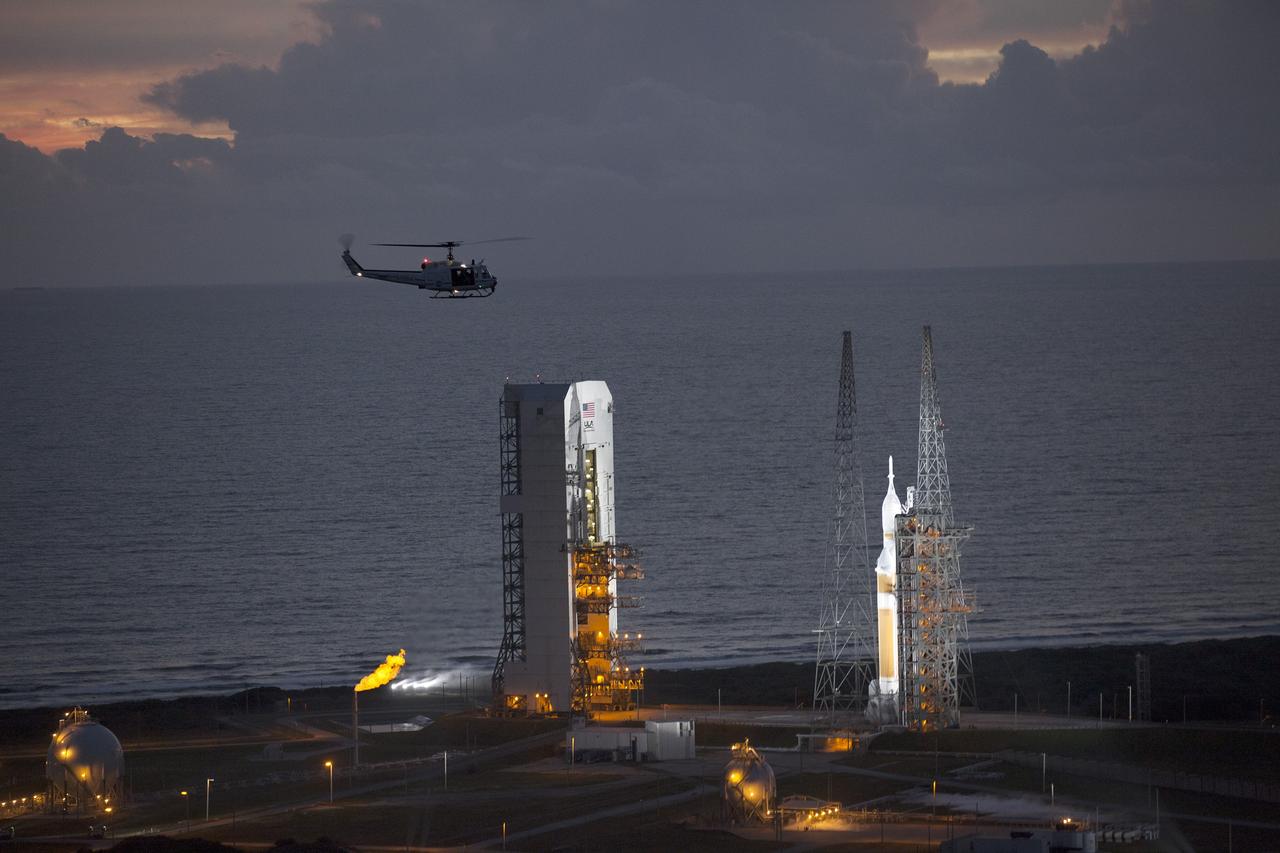
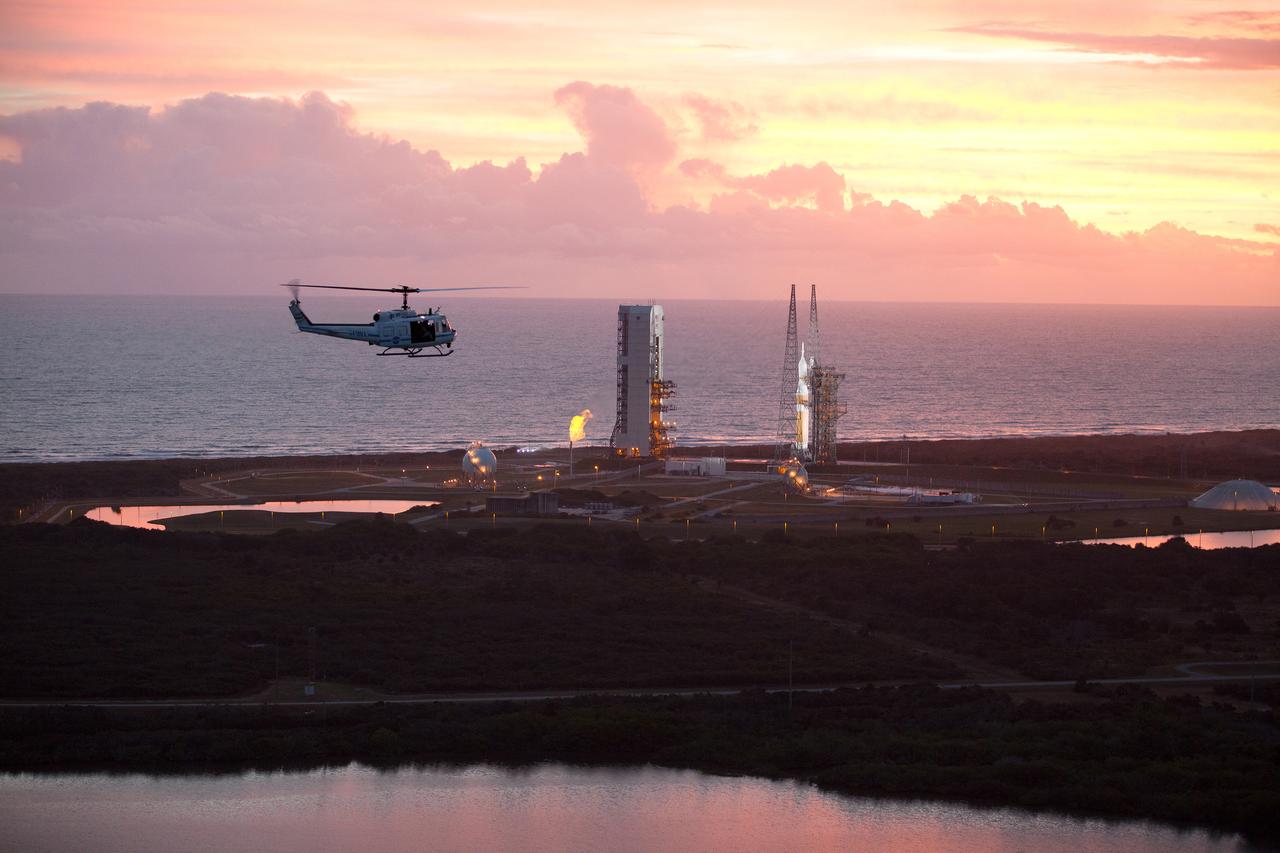
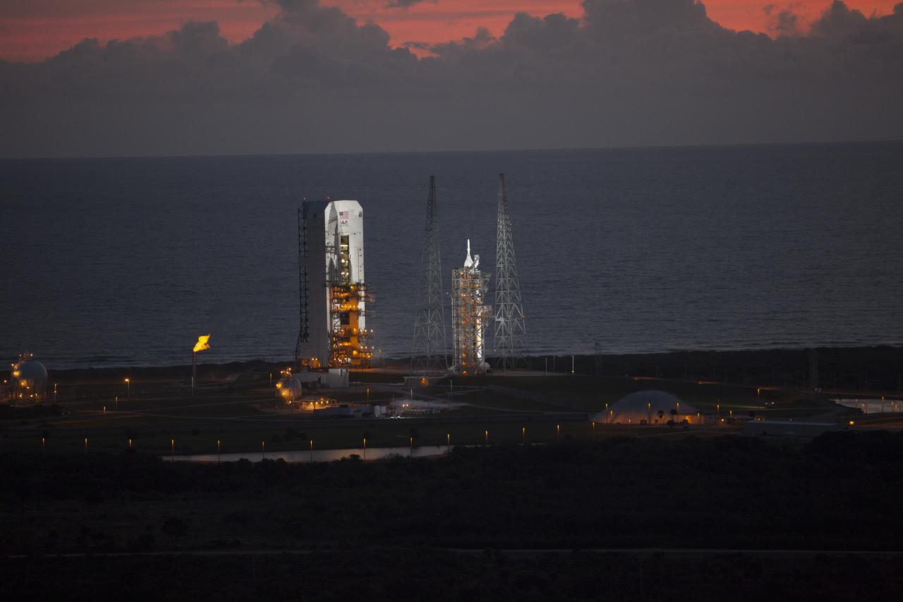
CAPE CANAVERAL, Fla. – This helicopter view of Space Launch Complex 37 at Cape Canaveral Air Force Station in Florida shows the United Launch Alliance Delta IV Heavy rocket as it stands ready to boost NASA's Orion spacecraft on a 4.5-hour mission. The liftoff was postponed because of an issue related to fill and drain valves on the Delta IV Heavy rocket that teams could not troubleshoot by the time the launch window expired. For more information, visit www.nasa.gov/orion Photo credit: NASA/Kim Shiflett
iss068e0420749 (Jan. 25, 2023) --- Roscosmos cosmonaut and Expedition 68 Commander Sergey Prokopyev connects valves and manipulates hoses to change gases from neon to argon for the Plasma Crystal experiment. The space physics study takes place inside the International Space Station's Columbus laboratory module and explores how clouds of highly charged particles, or plasma crystals, behave in microgravity.
ISS030-E-128752 (8 March 2012) --- NASA astronaut Dan Burbank, Expedition 30 commander, performs part one of the Water Recovery System-1 (WRS-1) repair in the Tranquility node of the International Space Station. Burbank removed and replaced the failed Catalytic Reactor (CR), and installed a temporary filter kit between the new CR and the Microbial Check Valve (MCV) to support a system flush of the new Orbital Replacement Unit (ORU).
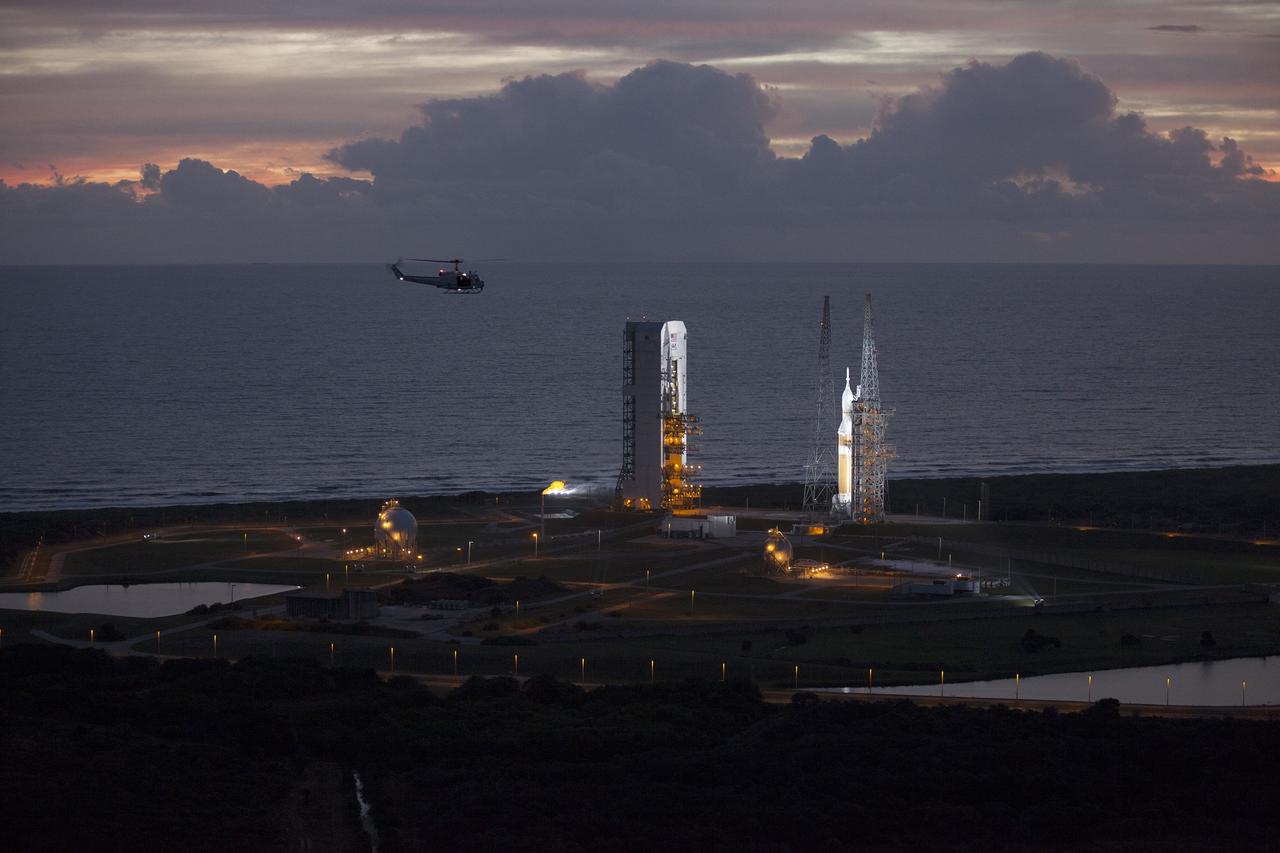
CAPE CANAVERAL, Fla. – This helicopter view of Space Launch Complex 37 at Cape Canaveral Air Force Station in Florida shows the United Launch Alliance Delta IV Heavy rocket as it stands ready to boost NASA's Orion spacecraft on a 4.5-hour mission. The liftoff was postponed because of an issue related to fill and drain valves on the Delta IV Heavy rocket that teams could not troubleshoot by the time the launch window expired. For more information, visit www.nasa.gov/orion Photo credit: NASA/Kim Shiflett
ISS030-E-032750 (11 Jan. 2012) --- NASA astronaut Dan Burbank, Expedition 30 flight commander, performs the Waste and Hygiene Compartment (WHC) yearly maintenance in the Tranquility node of the International Space Station. The maintenance included removing and replacing the urine hydraulic components which include urine lines, urine valve block and urine pressure sensors, and removing and replacing the Flush Water Tank Pressure Sensor.
This helicopter view of the NASA Causeway connecting NASA's Kennedy Space Center with Cape Canaveral Air Force Staton shows the thousands of vehicles parked where guests gather to see the launch of the Orion Exploration Flight Test-1 (EFT-1) on Dec. 4, 2014. The liftoff was postponed because of an issue related to fill and drain valves on the Delta IV Heavy rocket that teams could not troubleshoot by the time the launch window expired. Part of Batch image transfer from Flickr.
This helicopter view of Space Launch Complex 37 at Cape Canaveral Air Force Station in Florida shows the United Launch Alliance Delta IV Heavy rocket as it stands ready to boost NASA's Orion spacecraft on a 4.5-hour mission. The liftoff was postponed because of an issue related to fill and drain valves on the Delta IV Heavy rocket that teams could not troubleshoot by the time the launch window expired.
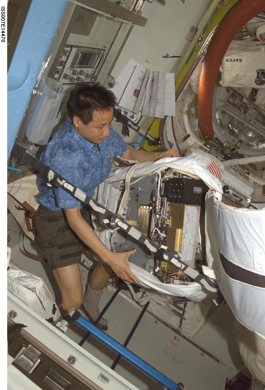
ISS007-E-14470 (5 September 2003) --- Astronaut Edward T. Lu, Expedition 7 NASA ISS science officer and flight engineer, performs routine maintenance on an Extravehicular Mobility Unit (EMU) space suit in the Quest airlock on the International Space Station (ISS). The work represents a mid-term checkout and included emptying and refilling the suit’s water tank and loops, cycling relief valves, checking sensors and collecting data, a leak check and running the suit’s fan for two hours to lubricate it.
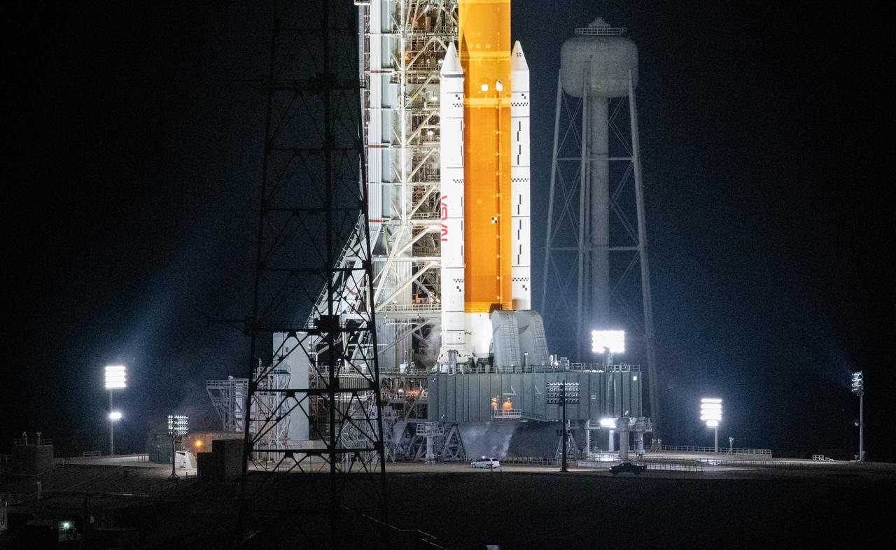
Vehicles with members of the red crew are seen as they arrive at Launch Pad 39B to make sure all connections and valves remain tight, Tuesday, Nov. 15, 2022, NASA’s Kennedy Space Center in Florida. NASA’s Artemis I flight test is the first integrated test of the agency’s deep space exploration systems: the Orion spacecraft, SLS rocket, and supporting ground systems. Launch of the uncrewed flight test is targeted for Nov. 16 at 1:04 a.m. EST. Photo Credit: (NASA/Joel Kowsky)
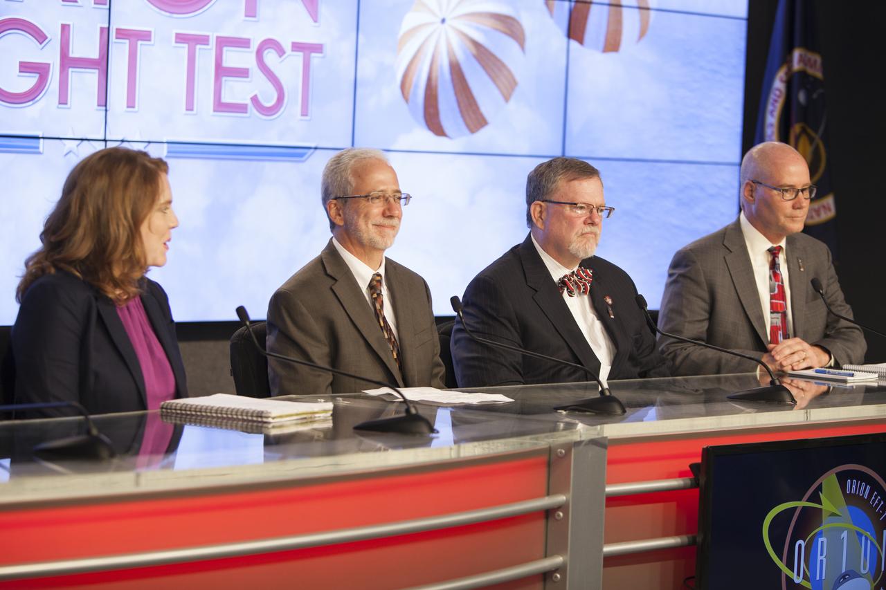
In the Kennedy Space Center’s Press Site auditorium, agency and industry leaders spoke to members of the news media about the postponement of the Orion Flight Test launch due to an issue related to fill and drain valves on the Delta IV Heavy rocket. From left are: Brandi Dean of NASA Public Affairs, Mark Geyer, NASA's Orion program manager, Mike Hawes, Lockheed Martin Orion Program manager, and Dan Collins, United Launch Alliance chief operating officer.
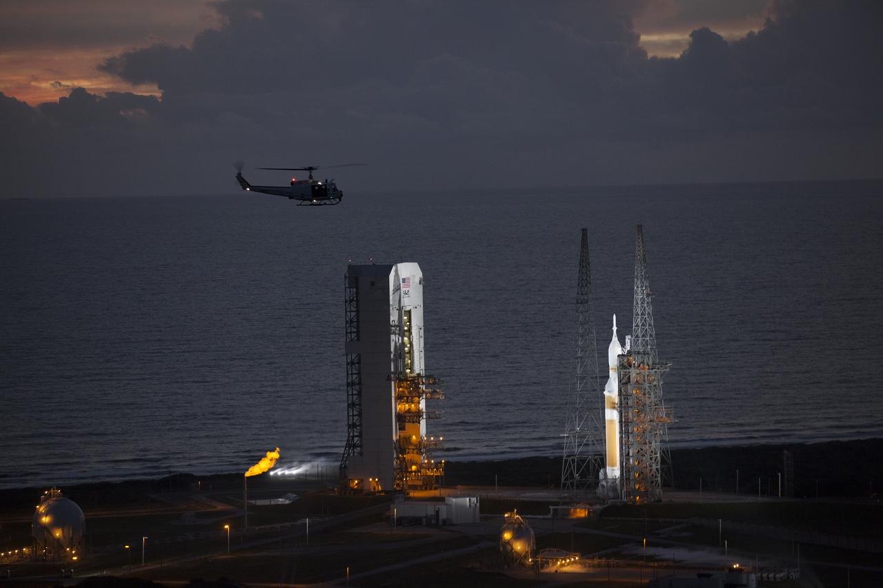
This helicopter view of Space Launch Complex 37 at Cape Canaveral Air Force Station in Florida shows the United Launch Alliance Delta IV Heavy rocket as it stands ready to boost NASA's Orion spacecraft on a 4.5-hour mission. The liftoff was postponed because of an issue related to fill and drain valves on the Delta IV Heavy rocket that teams could not troubleshoot by the time the launch window expired.
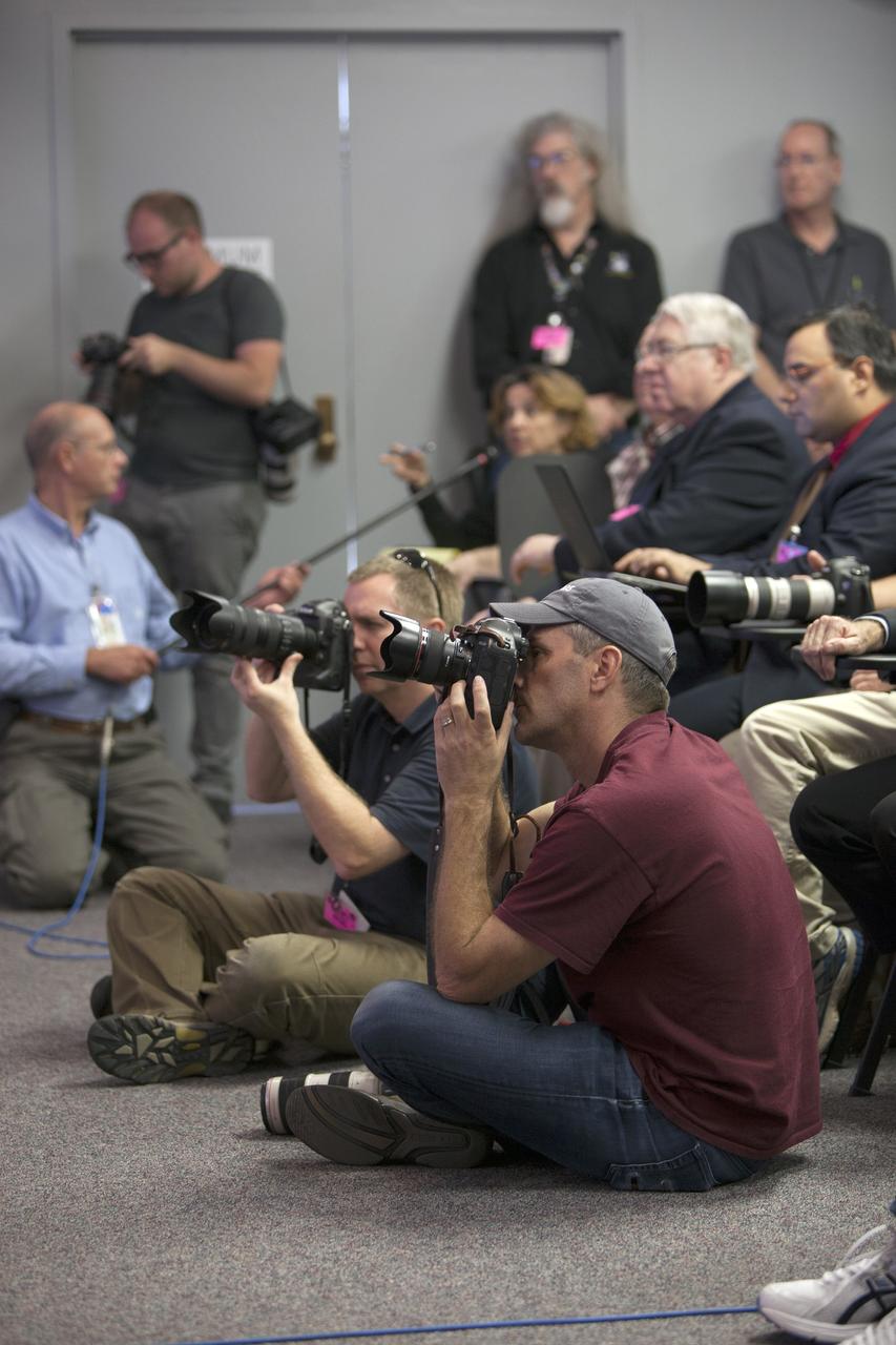
CAPE CANAVERAL, Fla. -- In the Kennedy Space Center’s Press Site auditorium, news media representatives listen and take photographs as NASA and industry leaders talk about the postponement of the Orion Flight Test launch due to an issue related to fill and drain valves on the Delta IV Heavy rocket. For more information, visit www.nasa.gov/orion Photo credit: NASA/Frankie Martin

This helicopter view of the NASA Causeway connecting NASA's Kennedy Space Center with Cape Canaveral Air Force Staton shows the thousands of vehicles parked where guests gather to see the launch of the Orion Flight Test. The liftoff was postponed because of an issue related to fill and drain valves on the Delta IV Heavy rocket that teams could not troubleshoot by the time the launch window expired.

CAPE CANAVERAL, Fla. – This helicopter view of the NASA Causeway connecting NASA's Kennedy Space Center with Cape Canaveral Air Force Staton shows the thousands of vehicles parked where guests gather to see the launch of the Orion Flight Test. The liftoff was postponed because of an issue related to fill and drain valves on the Delta IV Heavy rocket that teams could not troubleshoot by the time the launch window expired. For more information, visit www.nasa.gov/orion Photo credit: NASA/Kim Shiflett
CAPE CANAVERAL, Fla. -- In the Kennedy Space Center’s Press Site auditorium, Dan Collins, United Launch Alliance chief operating officer spoke to members of the news media about the postponement of the Orion Flight Test launch due to an issue related to fill and drain valves on the Delta IV Heavy rocket. For more information, visit www.nasa.gov/orion Photo credit: NASA/Frankie Martin
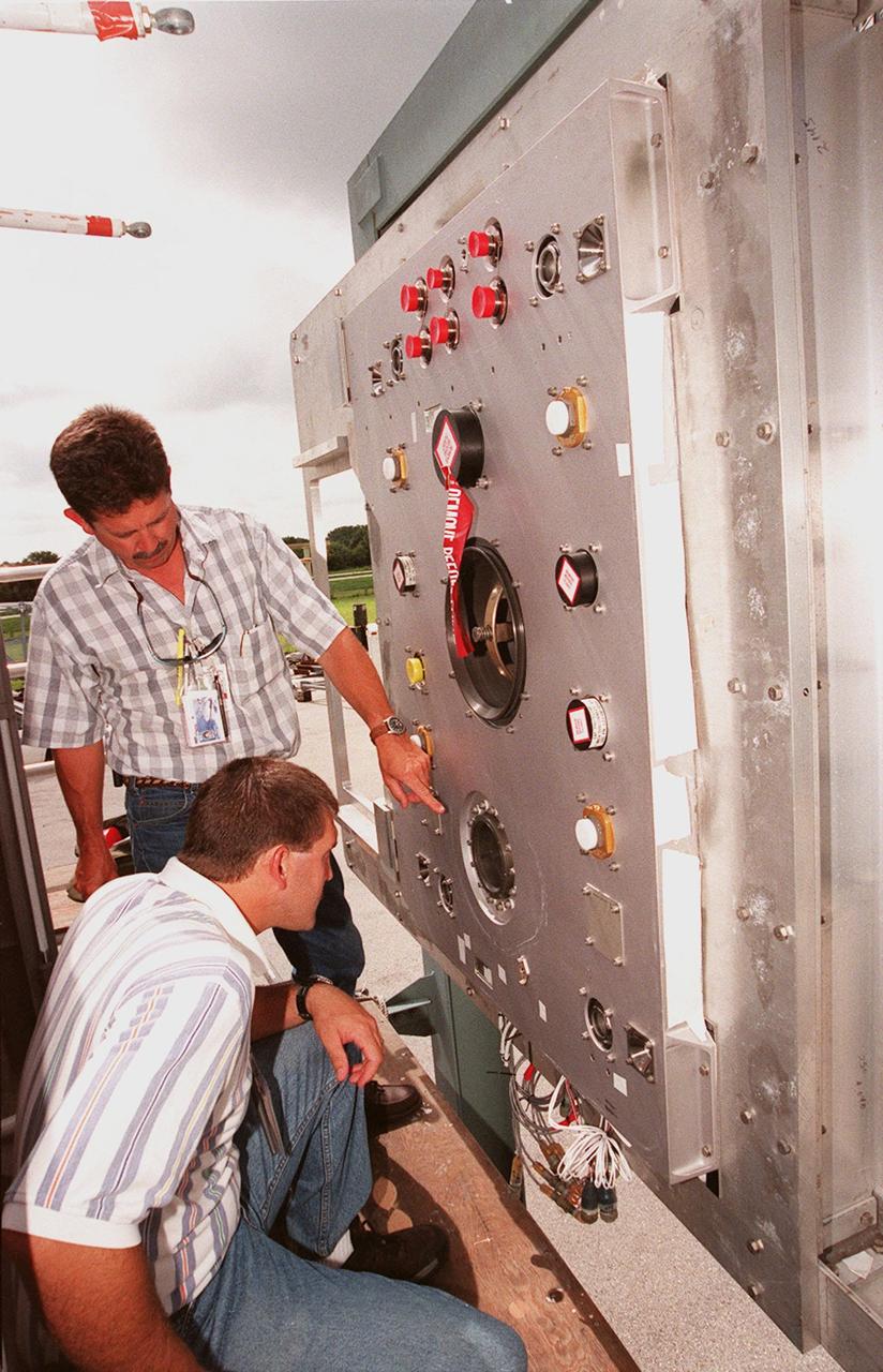
At the Launch Equipment Test Facility, , Will Reaves and Mike Solomon (kneeling), both with Lockheed Martin Technical Operations, observe parts of the X-33 umbilical system during testing. A team of Kennedy Space Center experts developed the umbilical system, comprising panels, valves and hoses that provide the means to load the X-33 with super-cold propellant. The X-33, under construction at Lockheed Martin Skunk Works in Palmdale, Calif., is a half-scale prototype of the planned operational reusable launch vehicle dubbed VentureStar

CAPE CANAVERAL, Fla. – This helicopter view of Space Launch Complex 37 at Cape Canaveral Air Force Station in Florida shows the United Launch Alliance Delta IV Heavy rocket as it stands ready to boost NASA's Orion spacecraft on a 4.5-hour mission. The liftoff was postponed because of an issue related to fill and drain valves on the Delta IV Heavy rocket that teams could not troubleshoot by the time the launch window expired. For more information, visit www.nasa.gov/orion Photo credit: NASA/Kim Shiflett
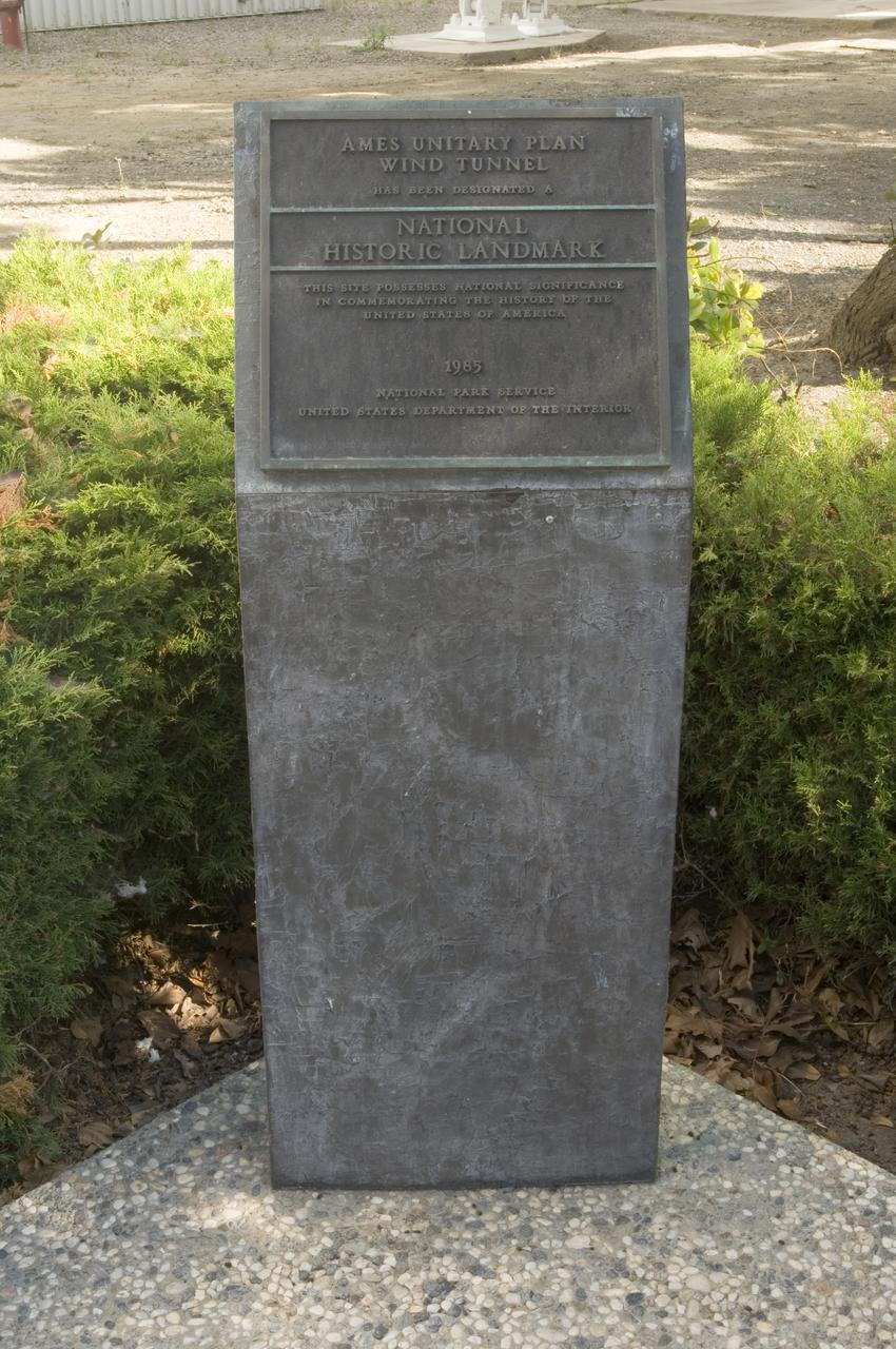
Ames and Moffett Field (MFA) historical sites and memorials Unitary Plan Wind Tunned plaza; display and historical site plaques with the NASA logo on the Wind Tunnel valve as a backdrop. Plaque depicts that Ames Unitary Plan Wind Tunnel has been designated a National Historic Landmark by the National Park Service, United States Department of the Interior 1985 The plaque reads; This site possesses national significance in commemorating the history of the United States of America. That ceremony took place on September 12, 1990