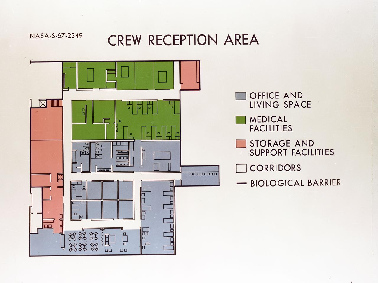
Artist's concept depicting the floor plan of the Crew Reception Area of the Lunar Receiving Laboratory (LRL), bldg 37.

Artist concept shows Galileo spacecraft while still approaching Jupiter having a satellite encounter. Galileo is flying about 600 miles above Io's volcano-torn surface, twenty times closer than the closest flyby altitude of Voyager in 1979.
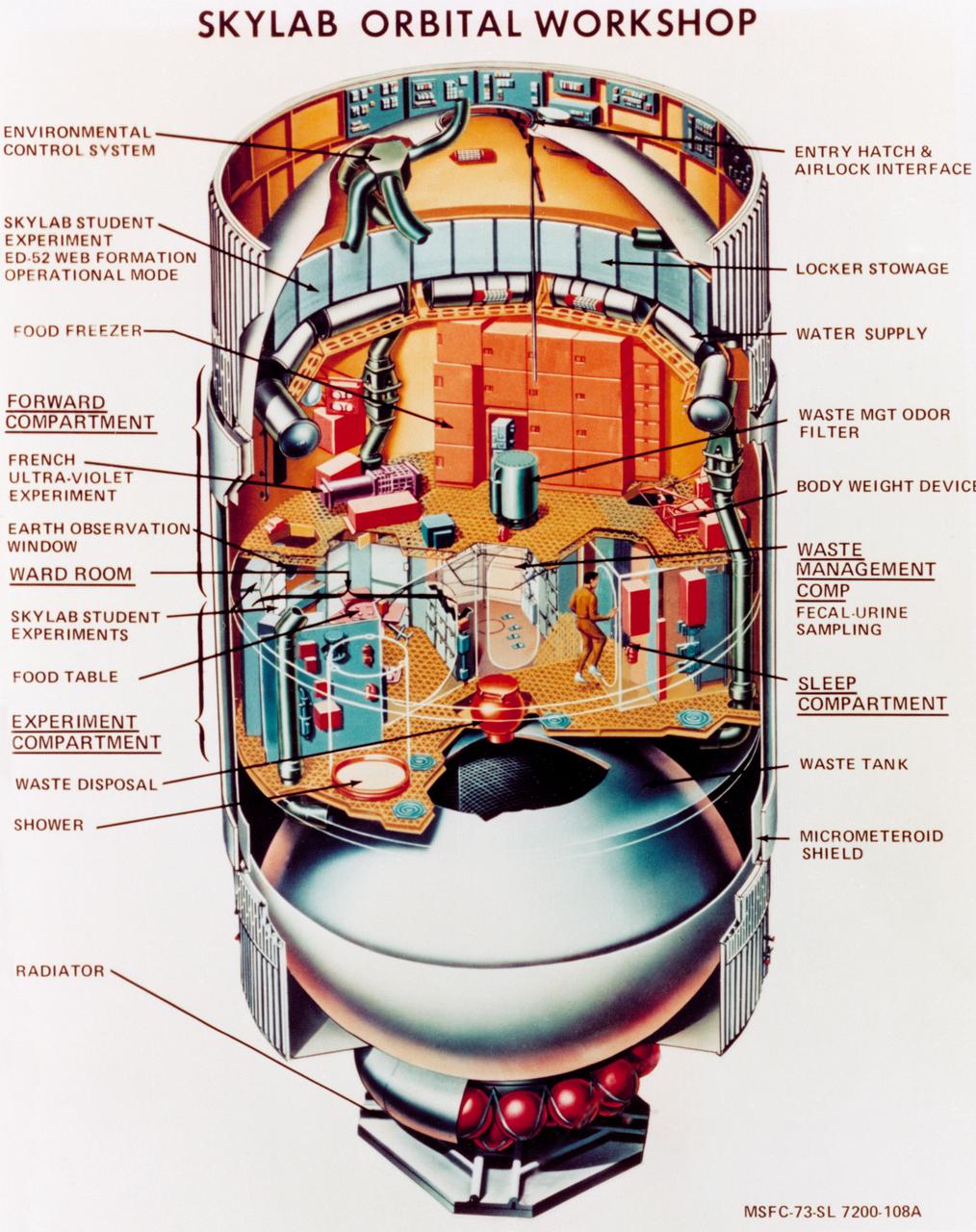
S73-23919 (May 1973) --- An artist's concept illustrating a cutaway view of the Skylab 1 Orbital Workshop (OWS). The OWS is one of the five major components of the Skylab 1 space station cluster which was launched by a Saturn V on May 14, 1973 into Earth orbit. Photo credit: NASA
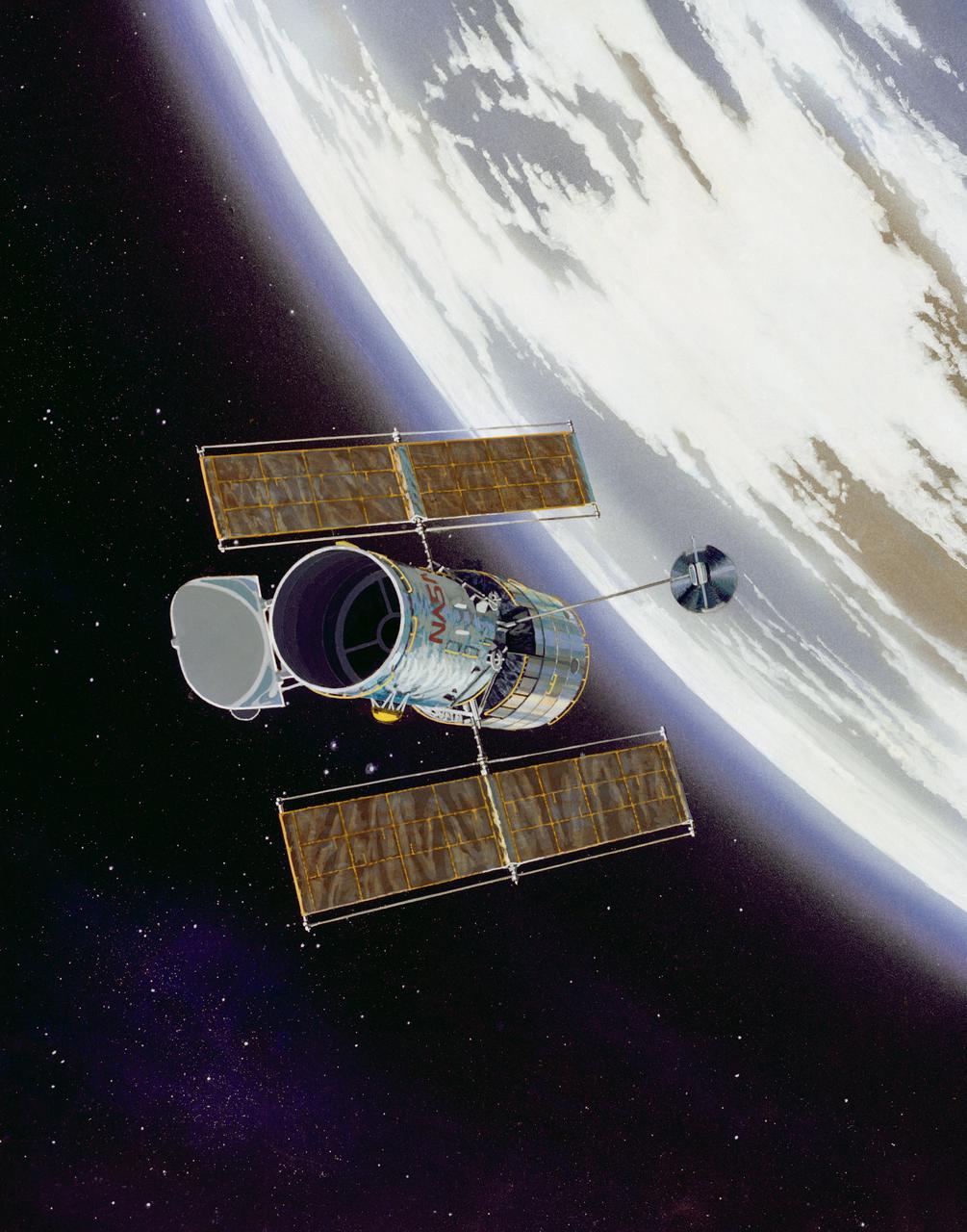
This artist concept shows the Hubble Space Telescope (HST) in operational configuration orbiting the Earth after its deploy from Discovery, Orbiter Vehicle (OV) 103 during STS-31. The high gain antennas (HGAs) and solar arrays (SAs) have been extended. HST's aperature door is open as it views the universe from a vantage point above the Earth's atmosphere. View provided by the Marshall Space Flight Center (MSFC).
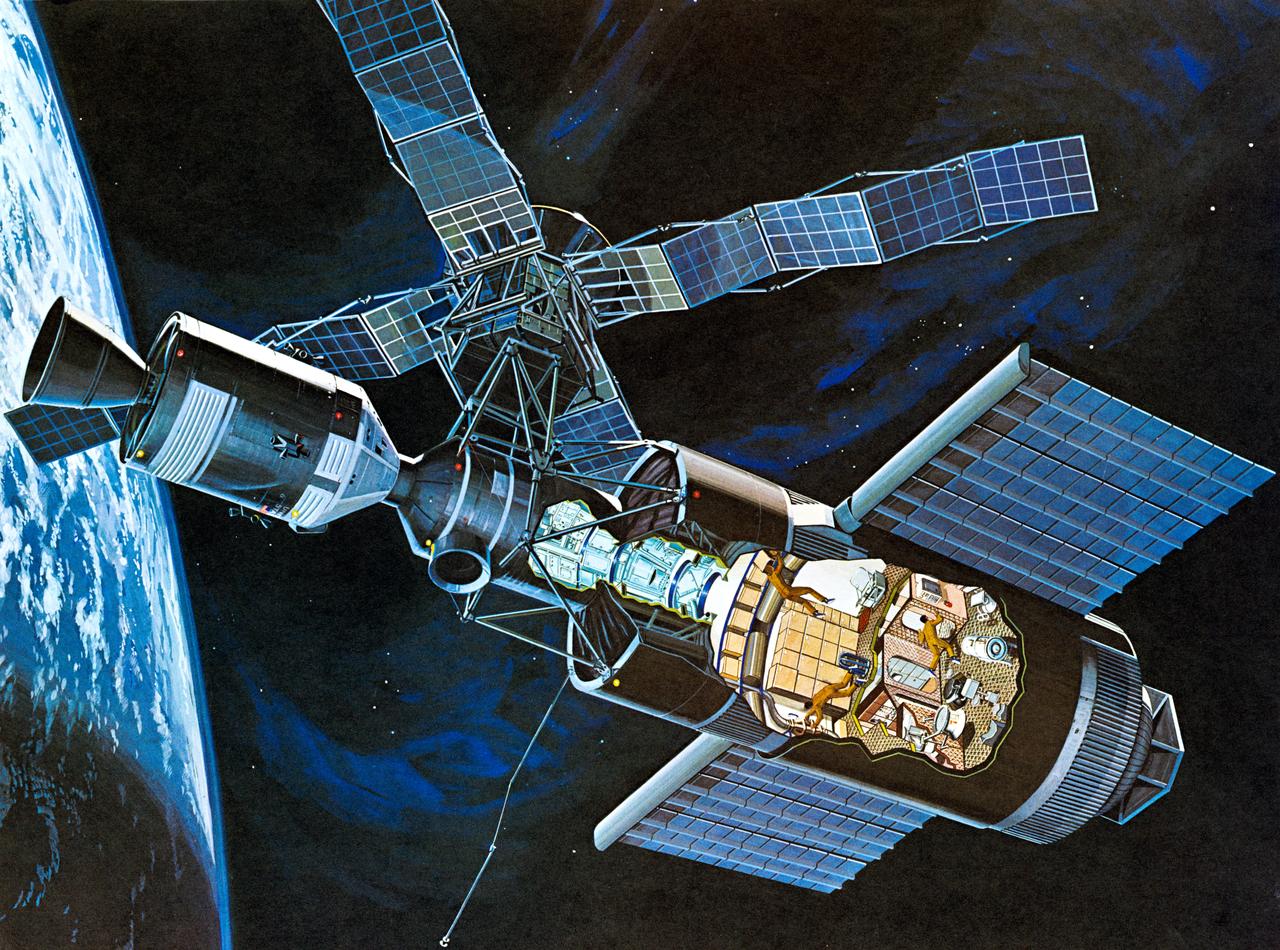
S71-52192 (1971) --- An artist's concept of the Skylab space station cluster in Earth's orbit. The cutaway view shows astronaut activity in the Orbital Workshop (OWS). The Skylab cluster is composed of the OWS, Airlock Module (AM), Multiple Docking Adapter (MDA), Apollo Telescope Mount (ATM), and the Command and Service Module (CSM). Photo credit: NASA
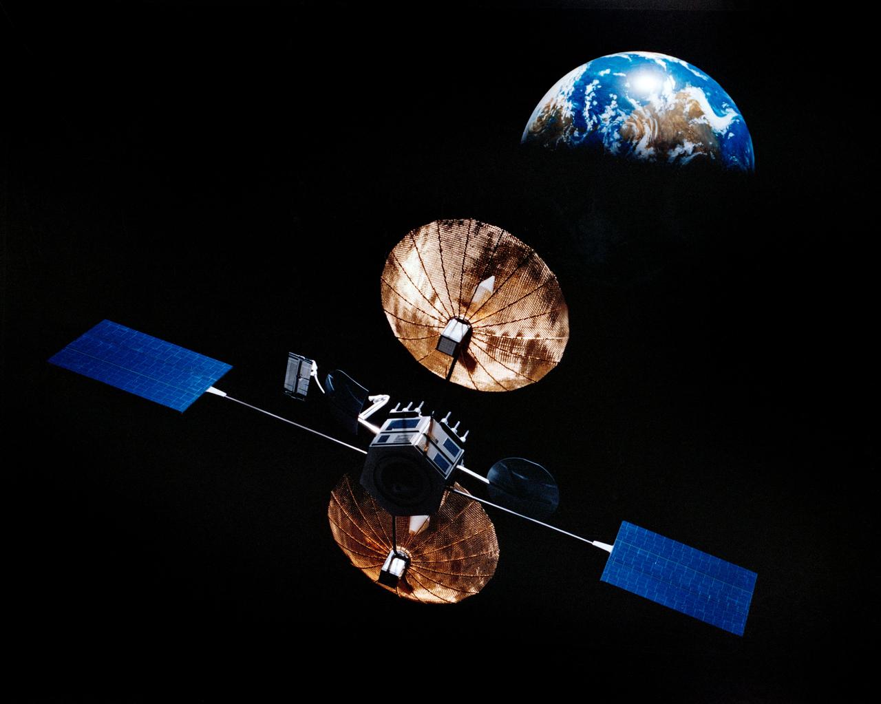
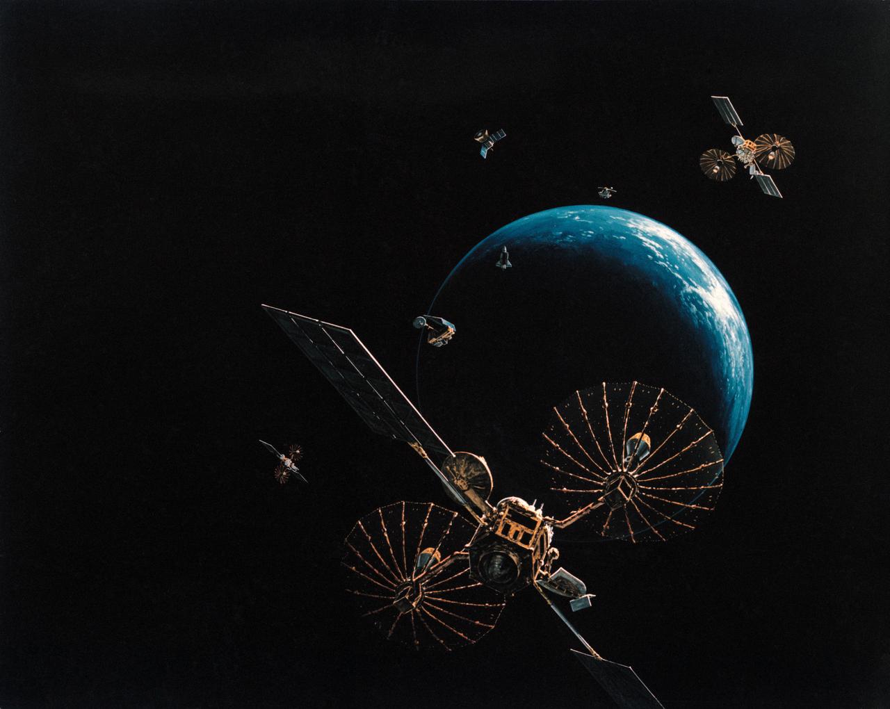
Artist concept of satellite with solar panels deployed in orbit above the earth.
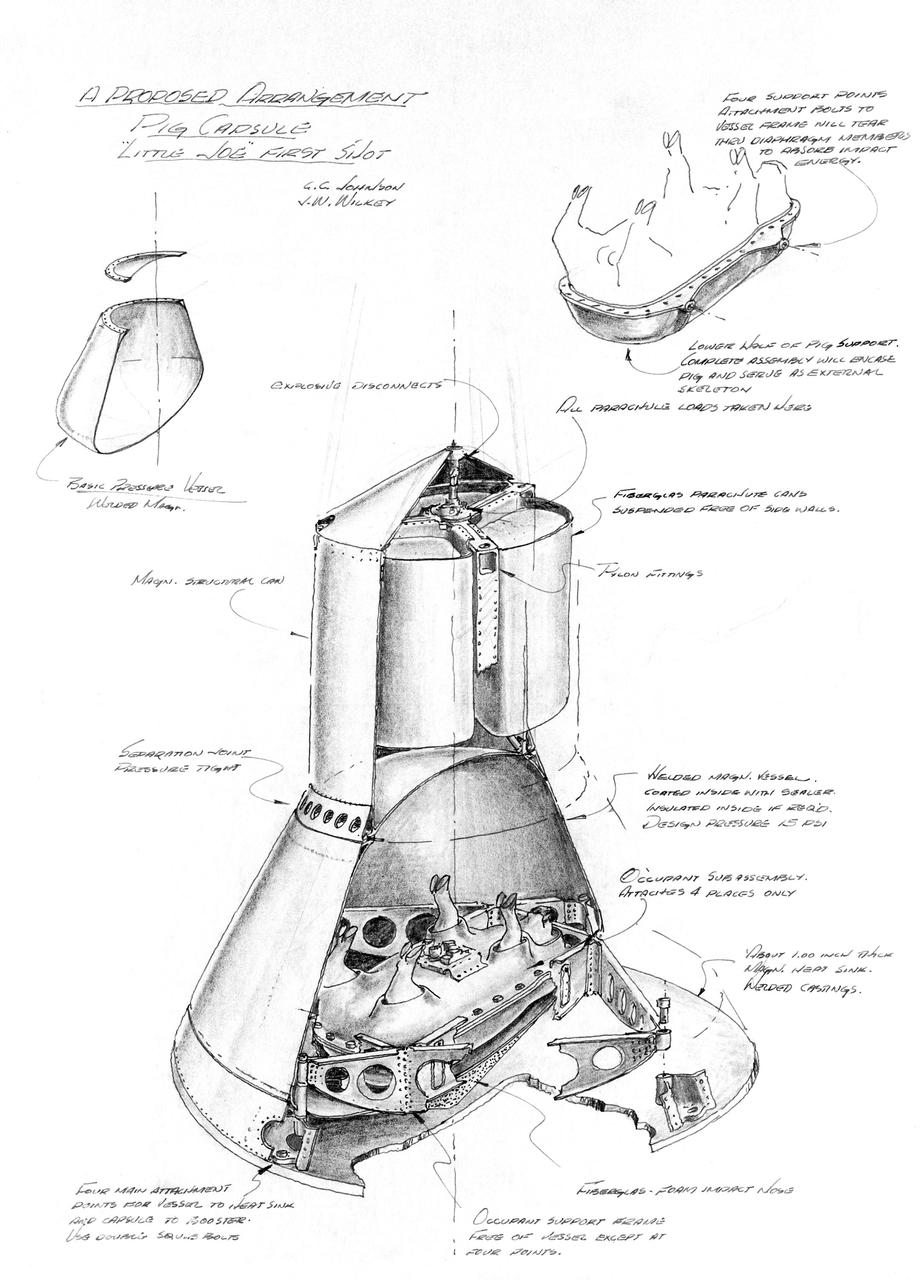
S63-19319 (October 1963) --- Pen and ink drawing of a proposed arrangement for a Pig Capsule in Little Joe capsule first shot. Photo credit: NASA
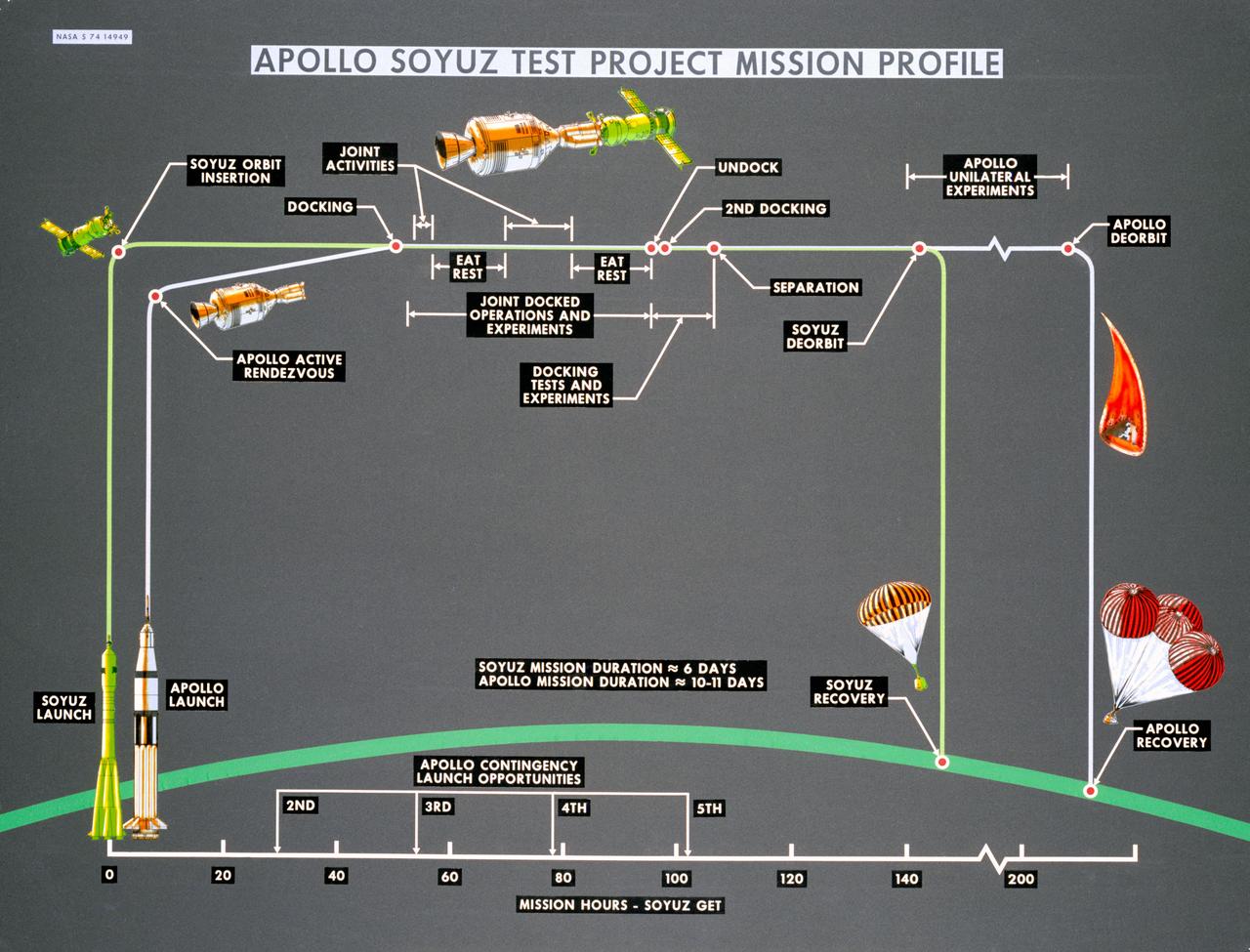
S74-14949 (October 1974) --- Artist?s drawings and call-outs depict phases of the joint U.S.-USSR Apollo-Soyuz Test Project, an Earth-orbital mission which will feature rendezvous and docking of the respective spacecraft of the two nations. ASTP crewmen for the USSR include Aleksey A. Leonov and Valeriy N. Kubasov. The astronaut team includes astronauts Thomas P. Stafford, Vance D. Brand and Donald K. Slayton. The mission is scheduled to take place in summer 1975.
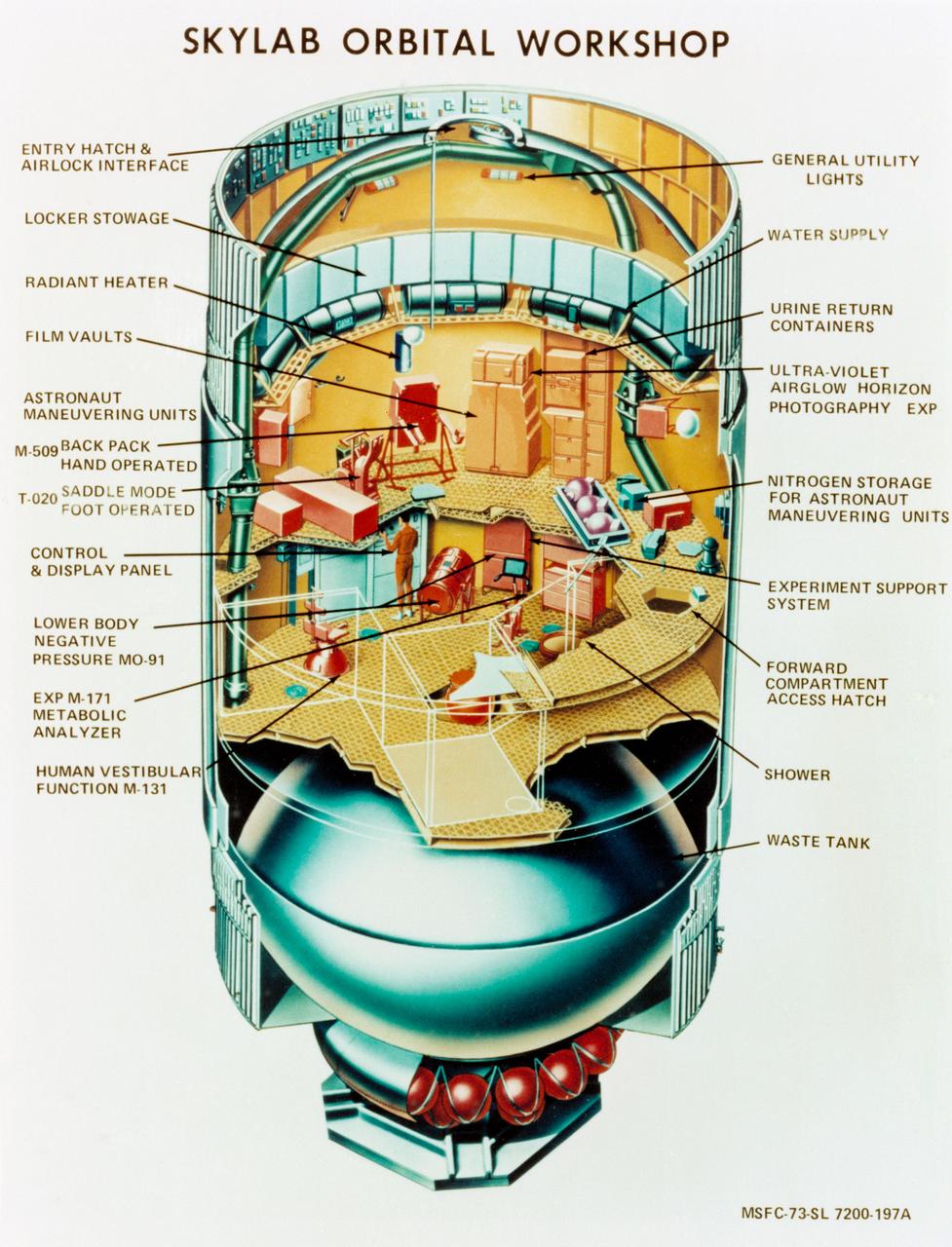
S73-23918 (May 1973) --- An artist's concept illustrating a cutaway view of the Skylab 1 Orbital Workshop (OWS). The OWS is one of the five major components of the Skylab 1 space station cluster which was launched by a Saturn V on May 14, 1973 into Earth orbit. Photo credit: NASA
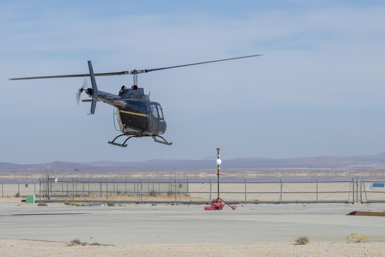
A Bell OH-58 Kiowa helicopter provided by Flight Research Inc. flies around a visual aid, known as a tetherball, created to serve as the pilot's visual height reference while performing handling qualities testing at NASA's Armstrong Flight Research Center in Edwards, California, Nov. 8-10. NASA's Advanced Air Mobility National Campaign used the helicopter to study urban air mobility vehicle and airspace requirements.
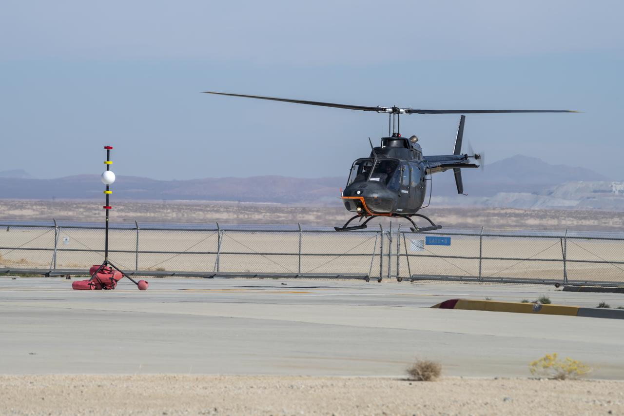
Flight Research Inc.'s Bell OH-58 Kiowa helicopter flies around a visual aid, known as a tetherball, created to serve as the pilot's visual height reference while performing handling qualities testing at NASA's Armstrong Flight Research Center in Edwards, California, Nov. 8-10. NASA's Advanced Air Mobility National Campaign used the helicopter to study urban air mobility vehicle and airspace requirements.
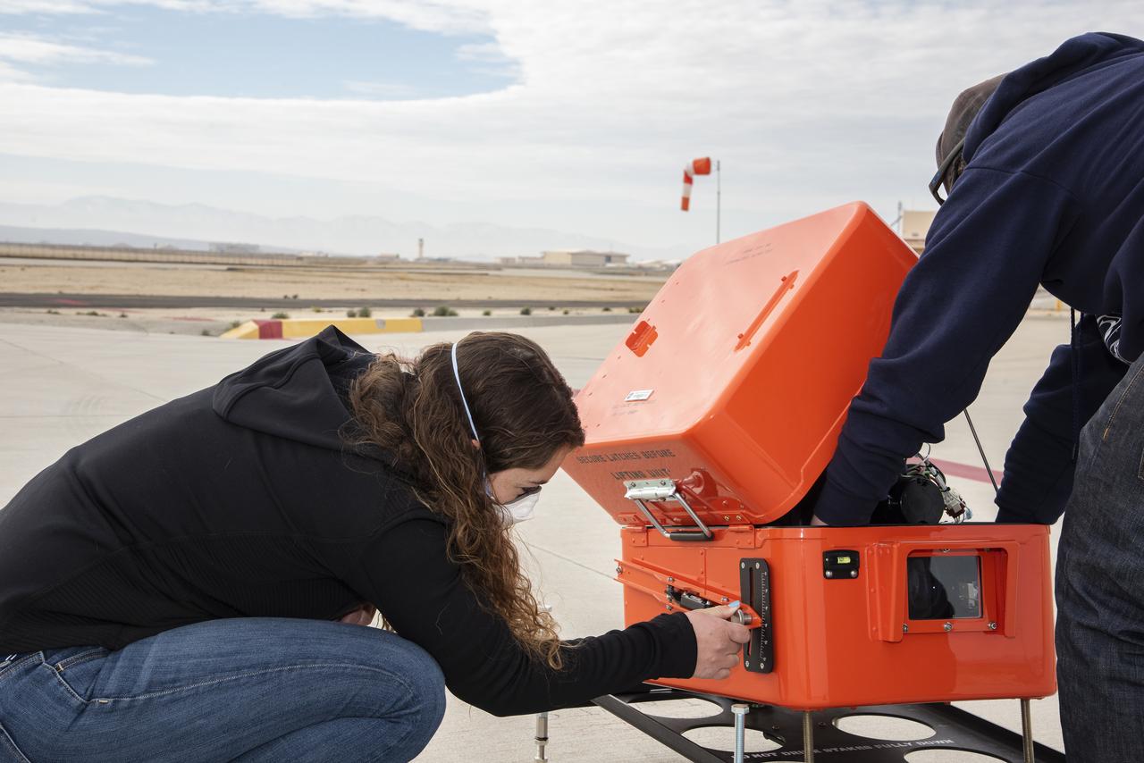
NASA’s flight systems engineer, Kassidy Mclaughlin adjusts a visual approach aid for aircraft called Pulse Light Approach Slope Indicator (PLASI). Dry run build-up test flights were conducted in 2021 at NASA’s Armstrong Flight Research Center in Edwards, California.

James Fesmire transfers a charged Cryogenic Flux Capacitor device to a bath of water in the Cryogenics Test Laboratory at NASA's Kennedy Space Center on Mar. 20, 2019. This demonstration is a visual aid that conveys that a large quantity of fluid is stored in the device at low temperature.
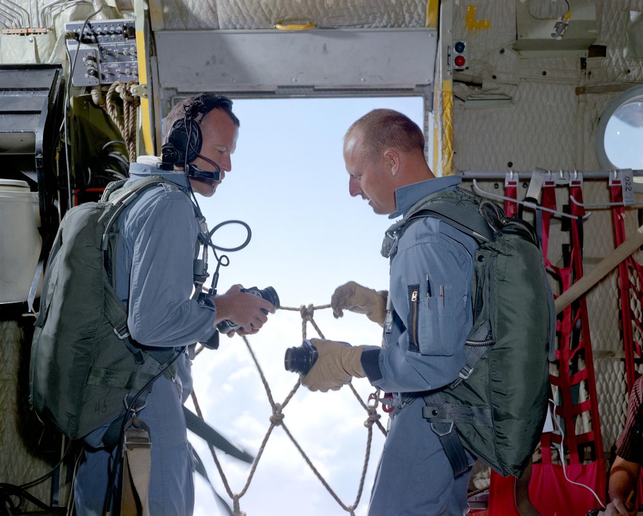
S65-35563 (18 June 1965) --- Astronauts L. Gordon Cooper Jr. (left), command pilot; and Charles Conrad Jr., pilot, the prime crew of the Gemini-5 spaceflight, prepare their cameras while aboard a C-130 aircraft flying near Laredo, Texas. The two astronauts are taking part in a series of visual acuity experiments to aid them in learning to identify known terrestrial features under controlled conditions. Knowledge gained from these experiments will have later application for space pilots identifying terrestrial features from space. Dr. John Billingham, chief, Environmental Physiology Branch, Crew Systems Division, is in charge of the Visual Acuity Experiments.
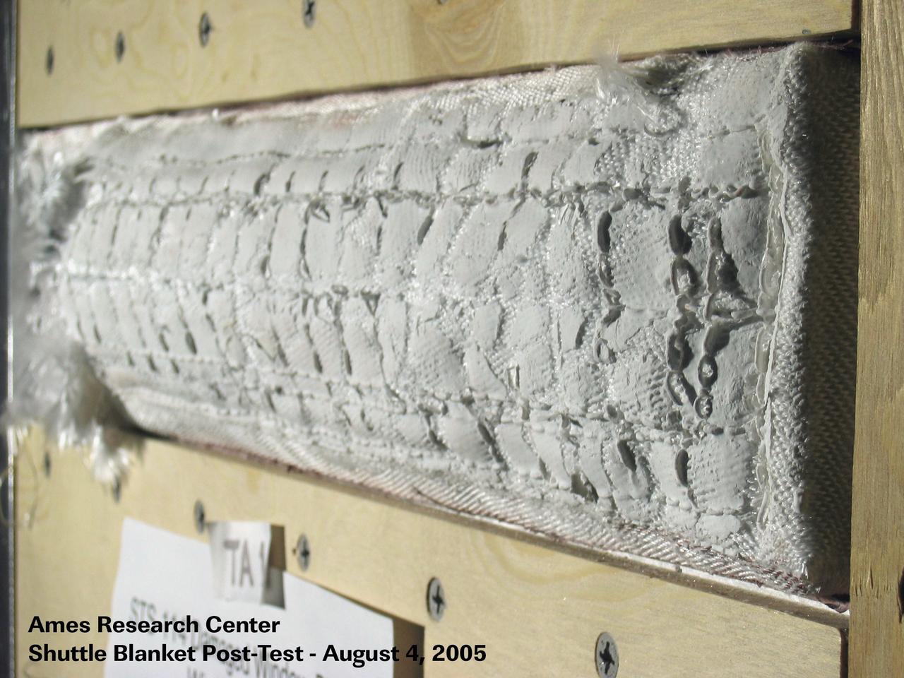
JSC2005-E-32511 (4 August 2005) --- One of four visual aids used by Shuttle Deputy Program Manager Wayne Hale during an August 4 press conference that dealt with important tests in wind tunnels at NASA's Ames Research Center. Engineers simulated the conditions of the Space Shuttle Discovery for a disrupted thermal blanket near the commander's window on the forward cabin of the spacecraft. Eventually it was decided that no additonal spacewalk work needed to be performed to fix the blanket.
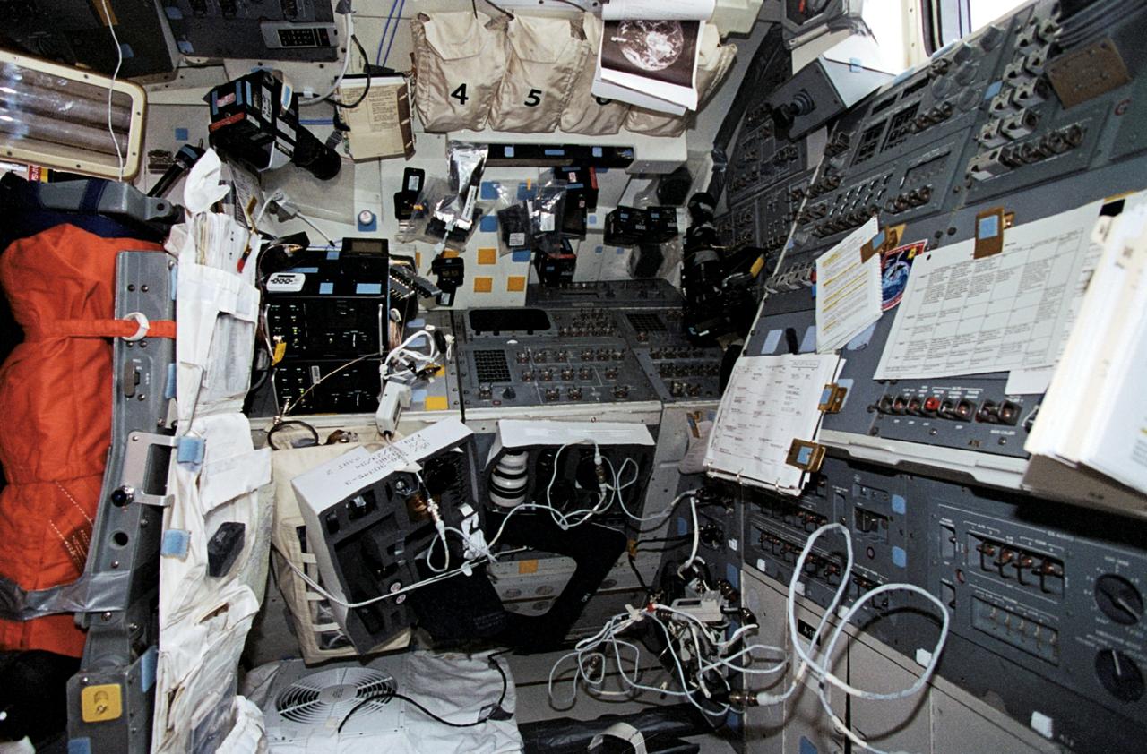
STS062-17-034 (4-18 March 1994) --- This scene, resembling a photographer's studio/laboratory, actually shows the aft flight deck of the Earth-orbiting Space Shuttle Columbia. A variety of cameras, lenses, visual aids and other gear are seen stowed around the flight deck. The five astronaut crew members devoted a large portion of their on-duty time at this workstation using some of this photographic equipment to record Earth imagery.
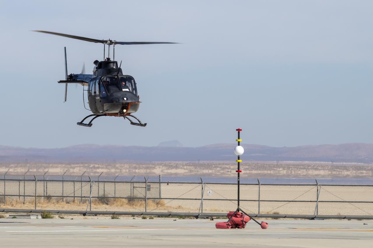
NASA's Advanced Air Mobility National Campaign created a visual aid, known as a tetherball, to serve as the helicopter pilot's height reference while flying different task elements at NASA's Armstrong Flight Research Center in Edwards, California, Nov. 8-10. The Bell OH-58 Kiowa helicopter provided by Flight Research Inc. was used to study urban air mobility vehicle performance and flying qualities requirements.
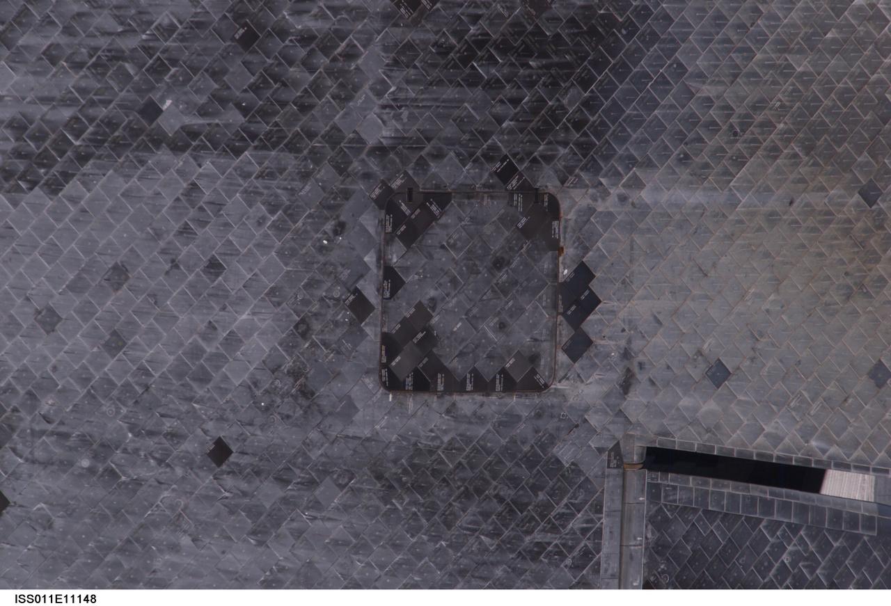
ISS011-E-11148 (28 July 2005) --- View of the Space Shuttle Discovery's underside (near the Orbital Maneuvering System pod), photographed as part of the survey sequence performed by the Expedition 11 crew during the STS-114 R-Bar Pitch Maneuver on Flight Day 3. This picture was used by Steve M. Poulos, Jr. Manager, Space Shuttle Vehicle Engineering Office, as one of his visual aids in a July 28, 2005 press conference in the Teague Auditorium at the Johnson Space Center.
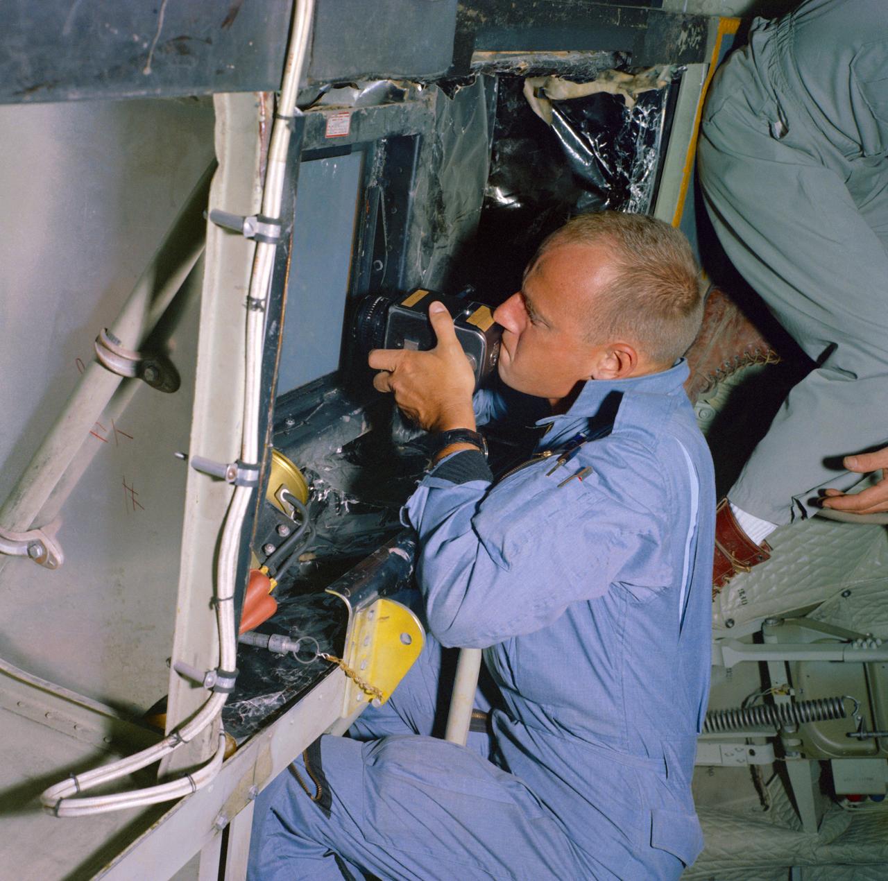
S65-35589 (18 June 1965) --- Astronaut Charles Conrad Jr., pilot for the prime crew on the Gemini-5 spaceflight, takes pictures of predetermined land areas during visual acuity experiments over Laredo, Texas. The experiments will aid in learning to identify known terrestrial features under controlled conditions. Knowledge gained from these experiments will have later application for space pilots identifying terrestrial features from space.
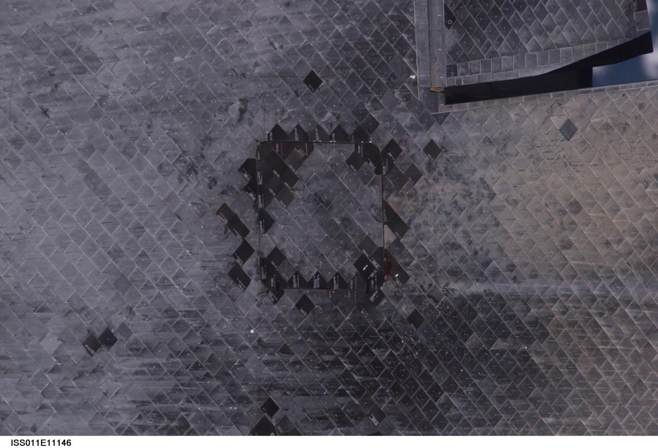
ISS011-E-11146 (28 July 2005) --- View of the Space Shuttle Discovery's underside (near Orbital Maneuvering System pod), photographed as part of the survey sequence performed by the Expedition 11 crew during the STS-114 R-Bar Pitch Maneuver on Flight Day 3. This picture was used by Steve M. Poulos, Jr. Manager, Space Shuttle Vehicle Engineering Office, as one of his visual aids in a July 28, 2005 press conference in the Teague Auditorium at the Johnson Space Center.

ISS011-E-11185 (28 July 2005) --- View of the Space Shuttle Discovery's underside starboard side wing and elevon, photographed as part of the survey sequence performed by the Expedition 11 crew during the STS-114 R-Bar Pitch Maneuver on Flight Day 3. This picture was used by Steve M. Poulos, Jr. Manager, Space Shuttle Vehicle Engineering Office, as one of his visual aids in a July 28, 2005 press conference in the Teague Auditorium at the Johnson Space Center.
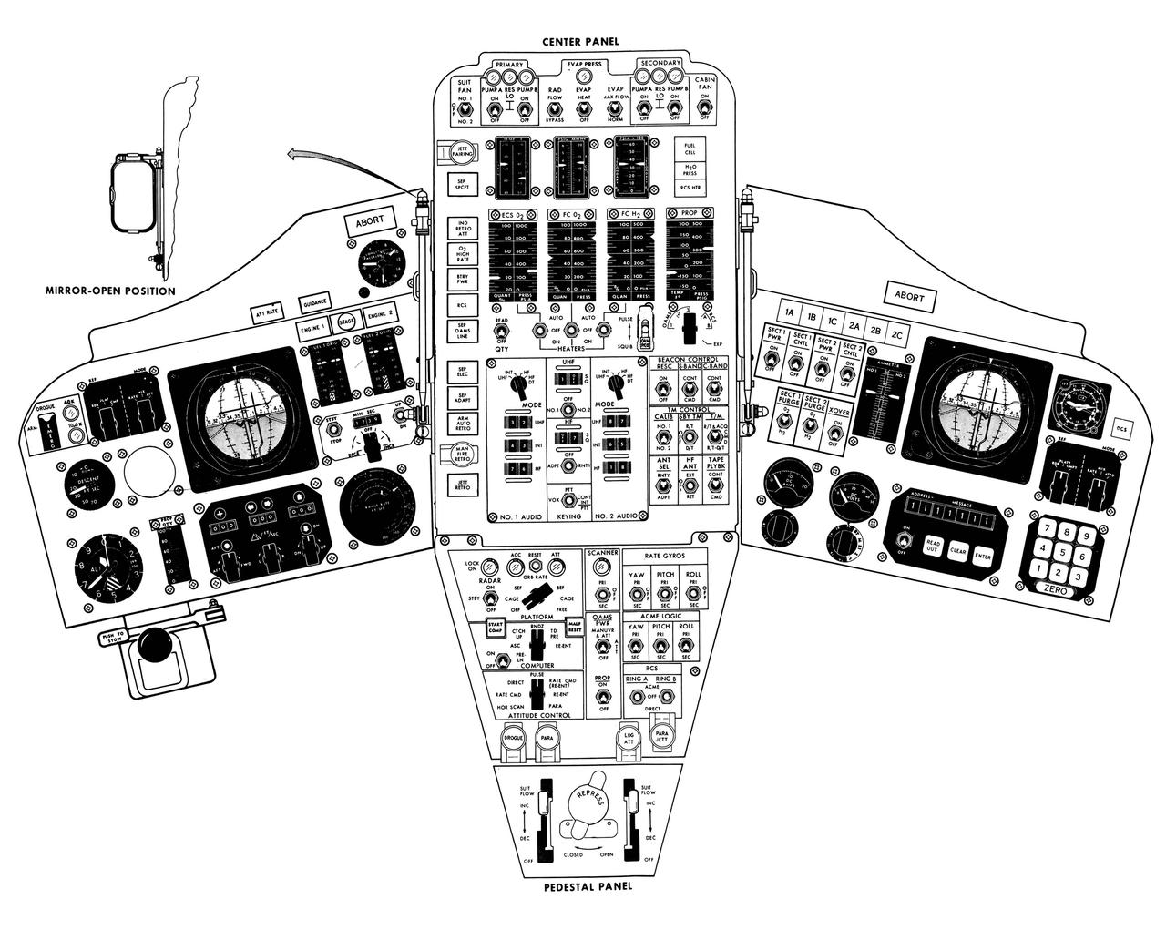
S65-14095 (1965) --- Artist concept of the Gemini spacecraft control panel.

S73-02395 (August 1973) --- An artist?s concept illustrating an Apollo-type spacecraft (on left) about to dock with a Soviet Soyuz-type spacecraft. A recent agreement between the United States and the Union of Soviet Socialist Republics provides for the docking in space of the Soyuz and Apollo-type spacecraft in Earth orbit in 1975. The joint venture is called the Apollo-Soyuz Test Project.
Artist concept shows the Tracking and Data Relay Satellite E (TDRS-E) augmenting a sophisticated TDRS system (TDRSS) communications network after deployment during STS-43 from Atlantis, Orbiter Vehicle (OV) 104. TDRS, built by TRW, will be placed in a geosynchronous orbit and after onorbit testing, which requires several weeks, will be designated TDRS-5. The communications satellite will replace TDRS-3 at 174 degrees West longitude. The backbone of NASA's space-to-ground communications, the TDRSs have increased NASA's ability to send and receive data to spacecraft in low-earth orbit to more than 85 percent of the time. Before TDRS, NASA relied solely on a system of ground stations that permitted communications only 15 percent of the time. Increased coverage has allowed onorbit repairs, live television broadcast from space and continuous dialogues between astronaut crews and ground control during critical periods such as Space Shuttle landings.

Labeled line drawing entitled GALILEO PROBE identifies the deceleration module aft cover, descent module, and deceleration module aeroshell configurations and dimensions prior to and during entry into Jupiter's atmosphere.
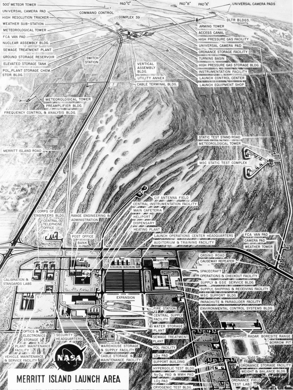
S63-23618 (December 1963) --- Aerial oblique artist concept of the Merritt Island Launch Complex, Merritt Island, Florida. Photo credit: NASA
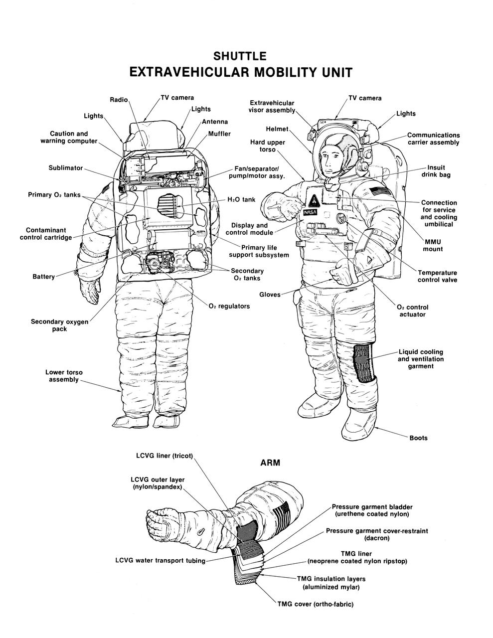
Labeled cutaway line drawing of the Shuttle extravehicular mobility unit (EMU) identifies its various components and equipment. The portable life support system (PLSS) and protective layers of fabric (thermal micrometeoroid garment (TMG)) incorporated in this extravehicular activity (EVA) space suit are shown.
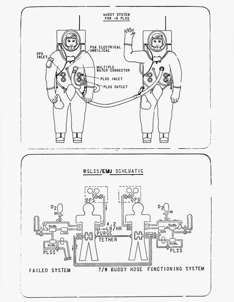
S70-56965 (December 1970) --- Drawing of the newly developed Buddy Secondary Life Support System (BSLSS). The life-sustaining system will be provided for the first time on the Apollo 14 lunar landing mission. The two flexible hoses, to be used on the second Apollo 14 extravehicular activity (EVA), will be among the paraphernalia on the Modular Equipment Transporter (MET) or two-wheeled workshop, and readily accessible in an emergency. During EVAs the Portable Life Support System (PLSS) supplies the astronaut with breathing and suit-pressurizing oxygen and water flow for the liquid-cooling garment -- a suit of knitted long underwear with thin tubing woven in the torso and limbs. The tubes carry water from a reservoir in the PLSS, and the circulating water serves to carry the astronaut's metabolic heat to a heat exchanger in the PLSS. Before the BSLSS was devised, the emergency tank was required to furnish not only suit pressure and breathing oxygen, but also cooling through a high oxygen flow rate. The BSLSS, by sharing the water supply between the two crewmen, stretches the time of the emergency oxygen from about 40 minutes to 60 to 75 minutes.
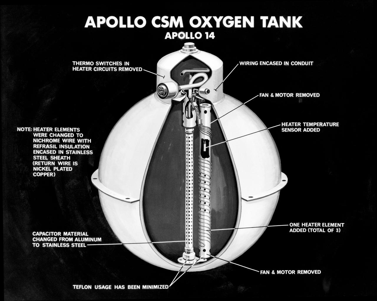
S71-16745 (January 1971) --- An artist's concept illustrating a cutaway view of one of the three oxygen tanks of the Apollo 14 spacecraft. This is the new Apollo oxygen tank design, developed since the Apollo 13 oxygen tank explosion. Apollo 14 has three oxygen tanks redesigned to eliminate ignition sources, minimize the use of combustible materials, and simplify the fabrication process. The third tank has been added to the Apollo 14 Service Module, located in the SM's sector one, apart from the pair of oxygen tanks in sector four. Arrows point out various features of the oxygen tank.

Space Station Freedom option A showing two Soyuz Assured Crew Return Vehicle (ACRV) capsules docked at berthing ports.
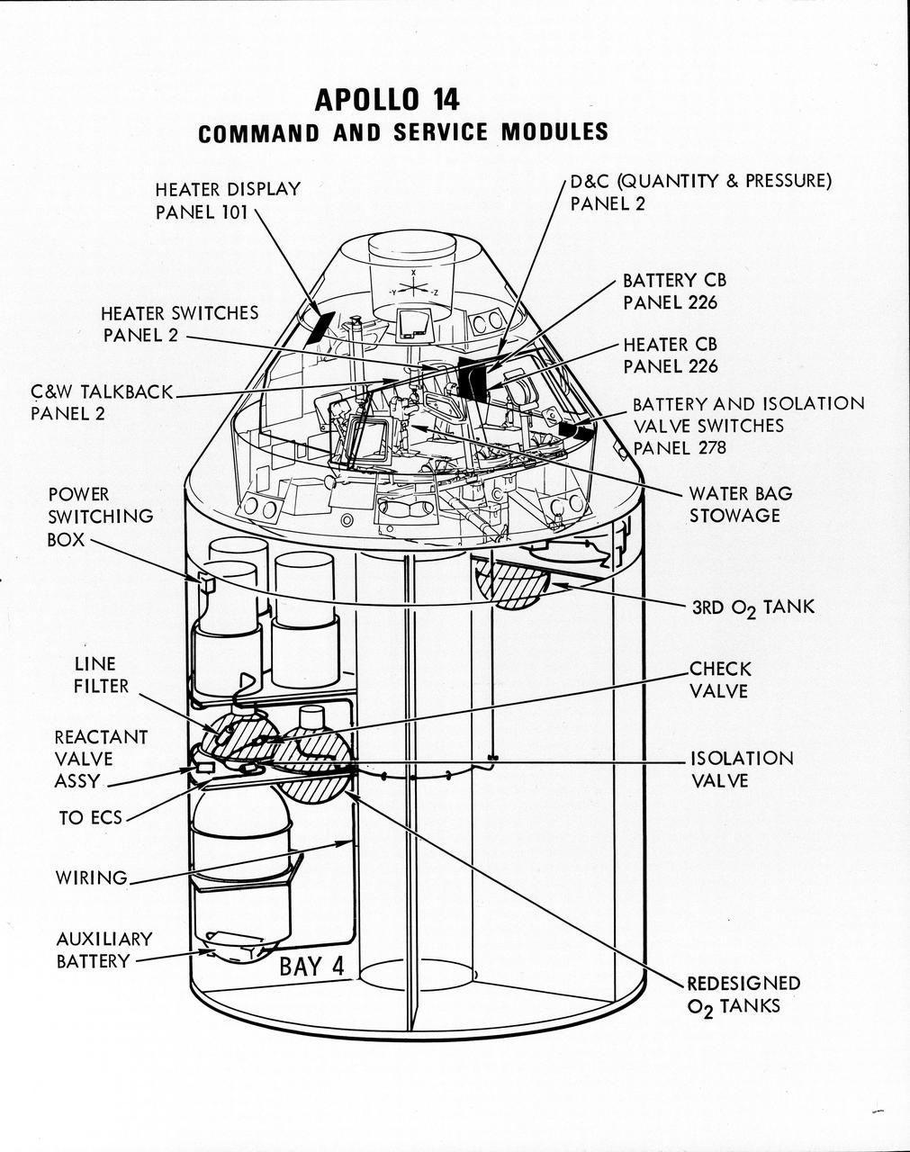
S71-16823 (January 1971) --- A line drawing illustrating a cutaway view of the Apollo 14 Command and Service Modules, showing the engineering changes in the CSM which were recommended by the Apollo 13 Review Board. (The Apollo 13 abort was caused by a short circuit and wiring overheating in one of the SM cryogenic oxygen tanks.) The major changes to the Apollo 14 CSM include adding a third cryogenic oxygen tank installed in a heretofore empty bay (in sector one) of the SM, addition of an auxiliary battery in the SM as a backup in case of fuel cell failure, and removal of destratification fans in the cryogenic oxygen tanks and removal of thermostat switches from the oxygen tank heater circuits. Provision for stowage of an emergency five-gallon supply of drinking water has been added to the CM.
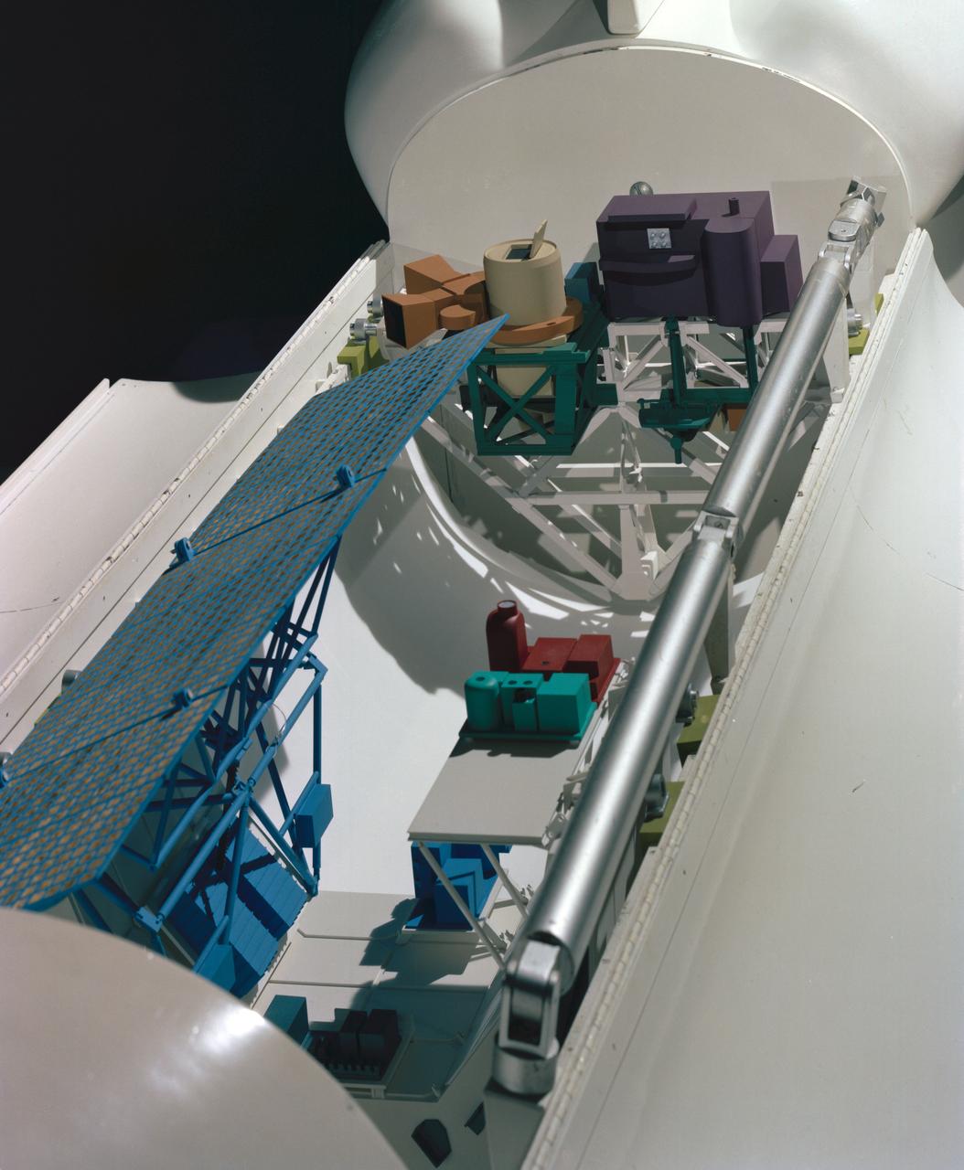
Model showing OSTA-3 and other payloads in the open shuttle orbiter cargo bay.
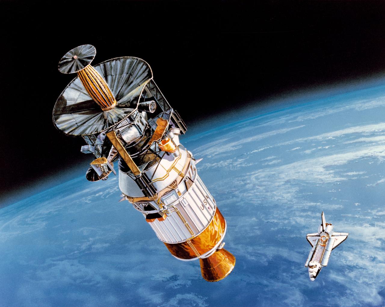
S89-42940 (April 1989) --- In this artist's rendition, the Galileo spacecraft is being boosted into its inter-planetary trajectory by the Inertial Upper Stage (IUS) rocket. The Space Shuttle Atlantis, which is scheduled to take Galileo and the IUS from Earth's surface into space, is depicted against the curve of Earth. Galileo will be placed on a trajectory to Venus, from which it will return to Earth at higher velocity and then gain still more energy in two gravity-assist passes, until it has enough velocity to reach Jupiter. Passing Venus, it will take scientific data using instruments designed for observing Jupiter; later, it will make measurements at Earth and the moon, crossing above the moon's north pole in the second pass. Between the two Earth passes, it will edge into the asteroid belt, beyond Mars' orbit; there, the first close-up observation of an asteroid is planned. Crossing the belt later, another asteroid flyby is possible.
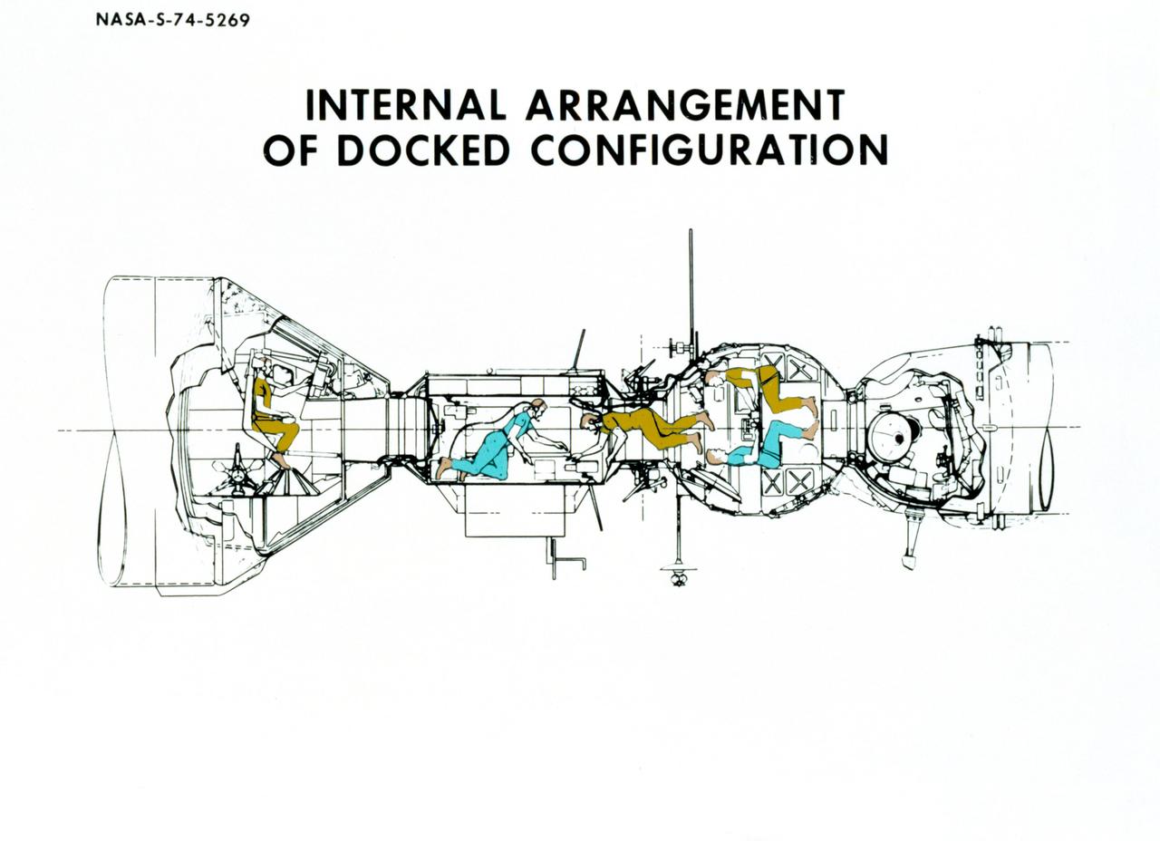
S74-05269 (December 1974) --- An artist?s drawing illustrating the internal arrangement of the Apollo and Soyuz spacecraft in Earth orbit in a docked configuration. The three American Apollo crewmen and the two Soviet Soyuz crewmen will transfer to each other?s spacecraft during the July 1975 ASTP mission. The four Apollo-Soyuz Test Project visible components are, left to right, the Apollo Command Module, the Docking Module, the Soyuz Orbital Module and the Soyuz Descent Vehicle.
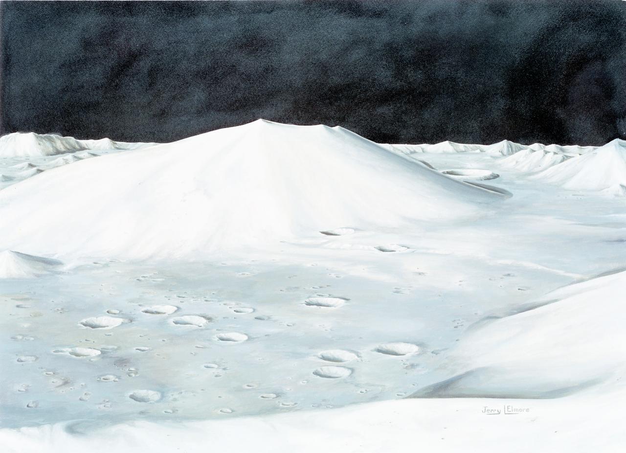
S72-49761 (October 1972) --- An artist's concept illustrating the topographical layout of the Taurus-Littrow landing site of the Apollo 17 lunar landing mission. The Lunar Module touchdown point is in the center of the smooth area in the middle of the picture. The imposing mountain in the center is South Massif. A portion of North Massif is in the lower right corner of the photograph. Note the ridge-like feature extending from South Massif to North Massif. The southern portion of the ridge is called Lee Scarp and the northerly portion Lincoln Scarp. (This concept is by JSC artist Jerry Elmore).
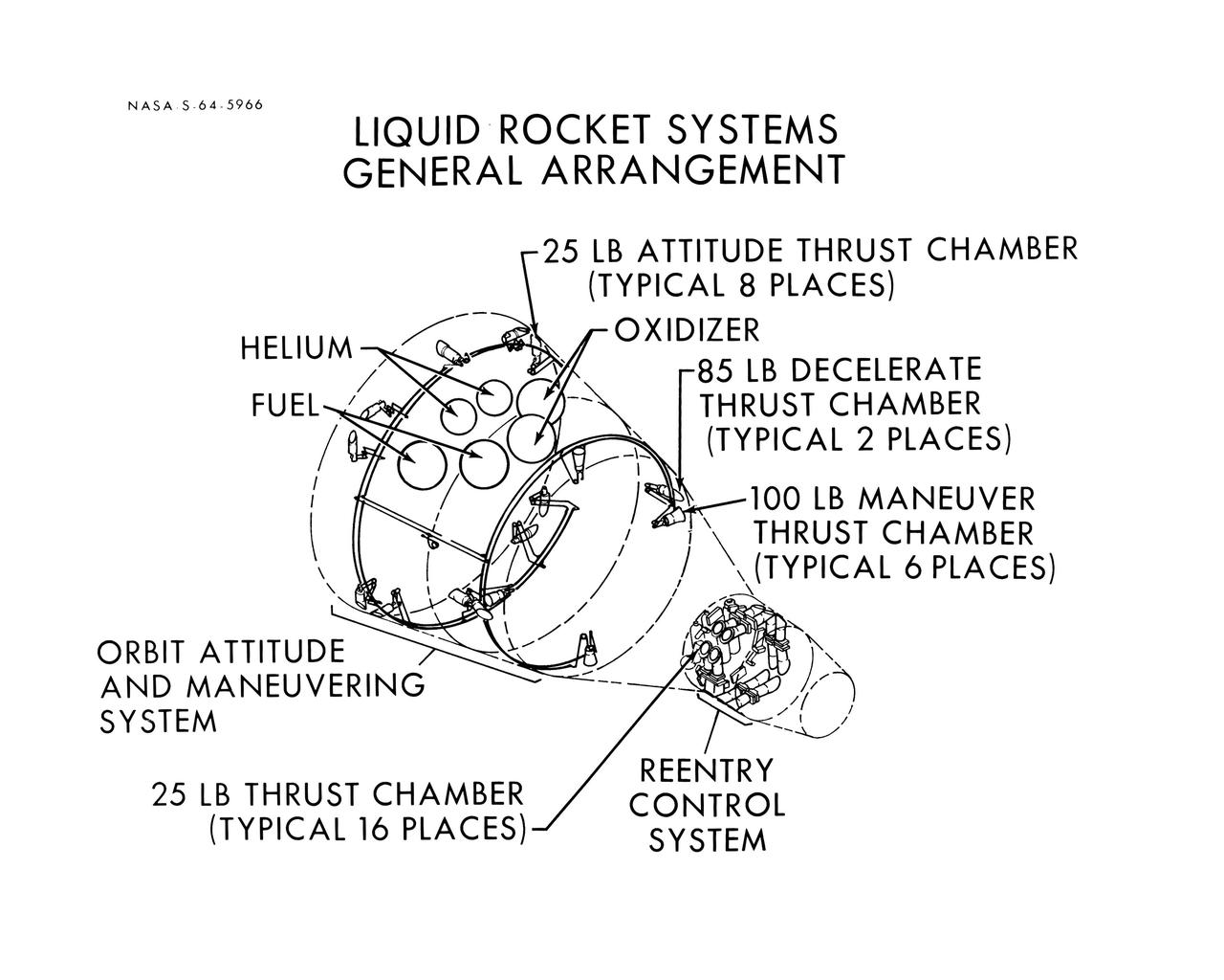
S64-05966 (1964) --- Diagram shows the general arrangement of the liquid rocket systems on the Gemini spacecraft are shown. The locations of the 25-pound, 85-pound and 100-pound thrusters of the orbital attitude and maneuver system and the 25-pound thrusters of the re-entry control system are shown.
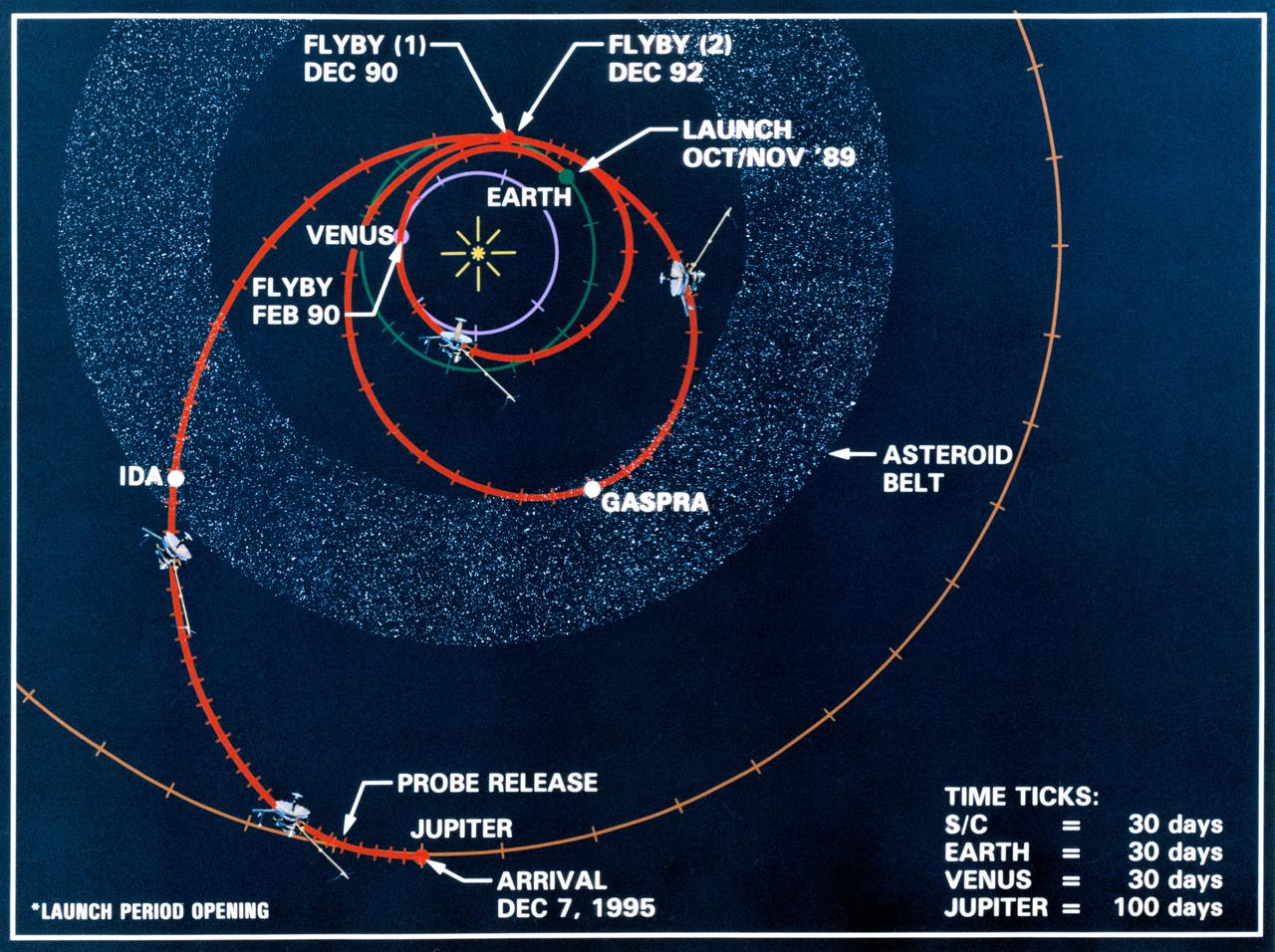
Line drawing charts the Galileo spacecraft's launch from low Earth orbit and its three planetary and two asteroid encounters in the course of its gravity-assisted flight to Jupiter. These encounters include Venus (February 1990), two Earth passes (December 1990 and December 1992), and the asteroids Gaspra and Ida in the asteroid belt. Galileo will release a probe and will arrive at Jupiter, 12-07-95.
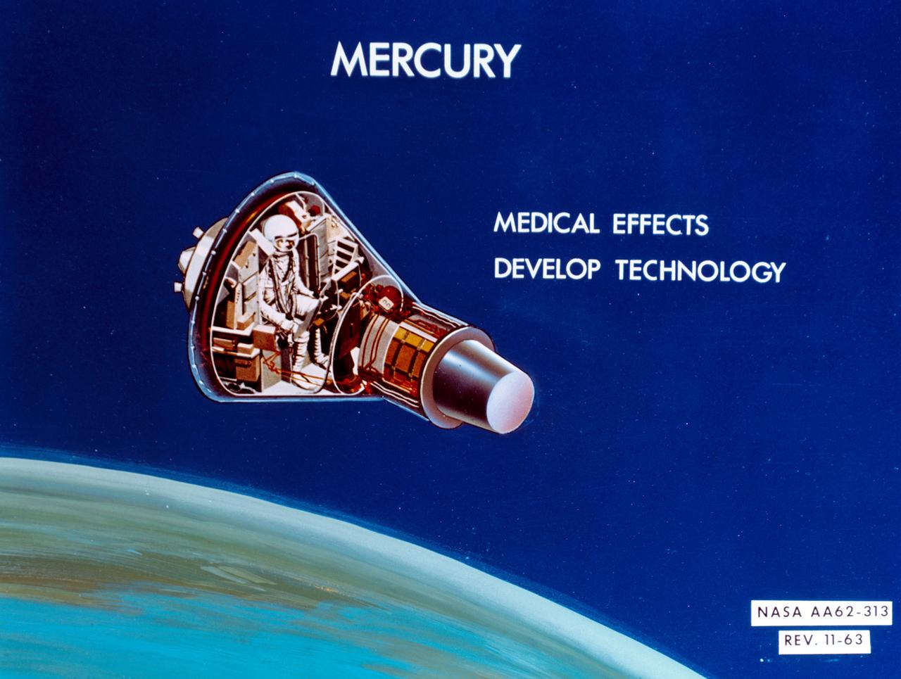
S64-14286 (11 Feb. 1964) --- An artist's concept of Mercury: Medical effects; develop technology. Photo credit: NASA
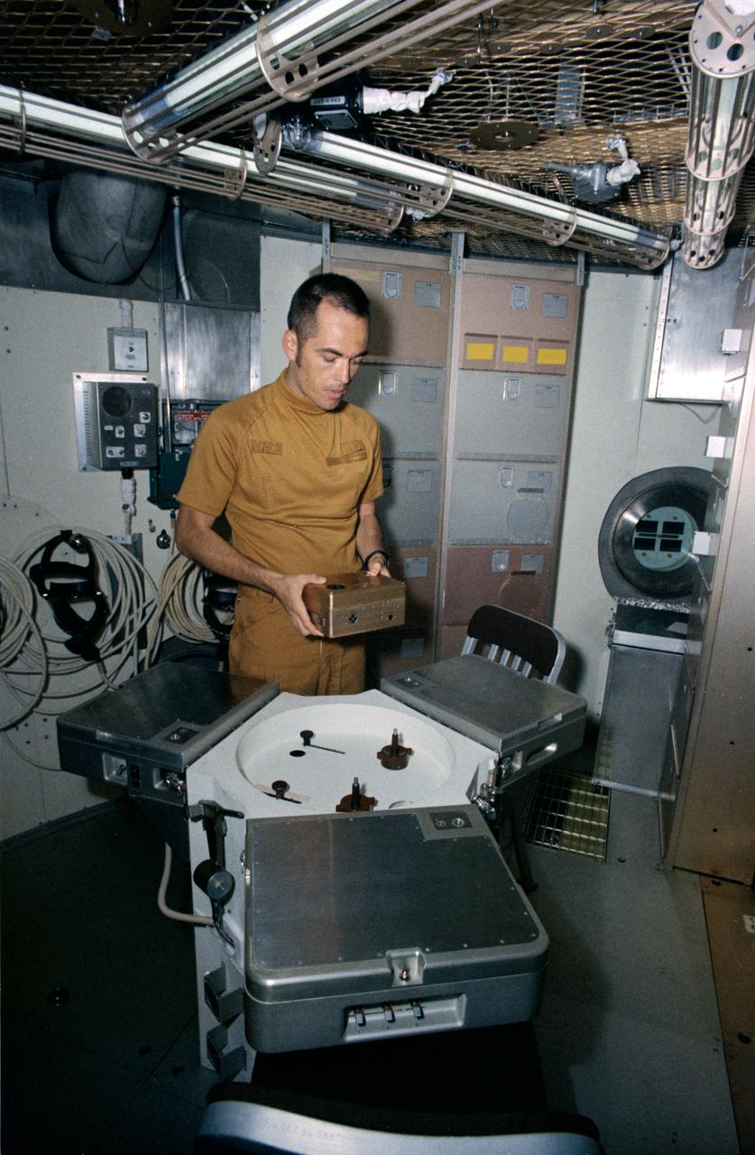
S72-43280 (15 June 1972) --- Astronaut Robert L. Crippen, Skylab Medical Experiment Altitude Test (SMEAT) commander, holds the training model of Skylab experiment T003, the aerosol analysis test, in this preview of SMEAT activity. He is part of a three-man SMEAT crew who will spend up to 56 days in the Crew Systems Division's 20-foot altitude chamber at the NASA Manned Spacecraft Center (MSC) beginning in mid-July to obtain medical data and evaluate medical experiment equipment for Skylab. The two crew members not shown in this view are astronauts Karol J. Bobko, SMEAT pilot, and Dr. William E. Thornton, SMEAT science pilot. Photo credit: NASA
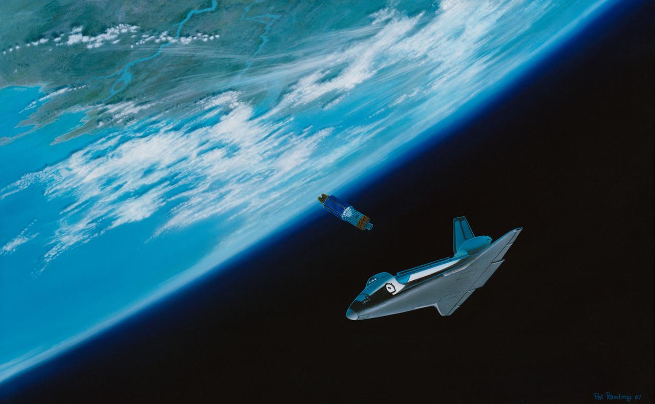
STS-26 Discovery, Orbiter Vehicle (OV) 103, artwork depicts tracking and data relay satellite C (TDRS-C) deployment. OV-103 orbits above Earth in bottom-to-sun attitude, moments after TDRS-C's release into space. TDRS-C is seen just below open payload bay (PLB). Artwork was done by Pat Rawlings of Eagle Engineering.
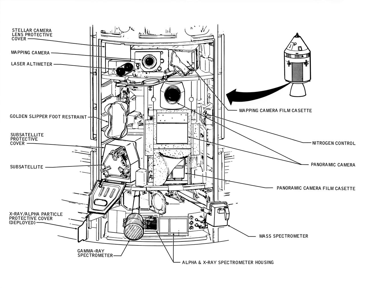
A line drawing illustrating the layout of the Scietific Instrument Module (SIM) of the Apollo 16 Service Module. Shown here is the location in the SIM bay of the equipment for each orbital experiment. Arrows point to various components of the SIM bay. The sensors for the gamma ray spectrometer and the mas spectrometer both extend outward on a boom about 25 feet when the instruments are in use. The subsatellite is launched while the Service Module is in orbit around the moon. The film cassettes must be retrieved prior to Command Module/Service Module separation.
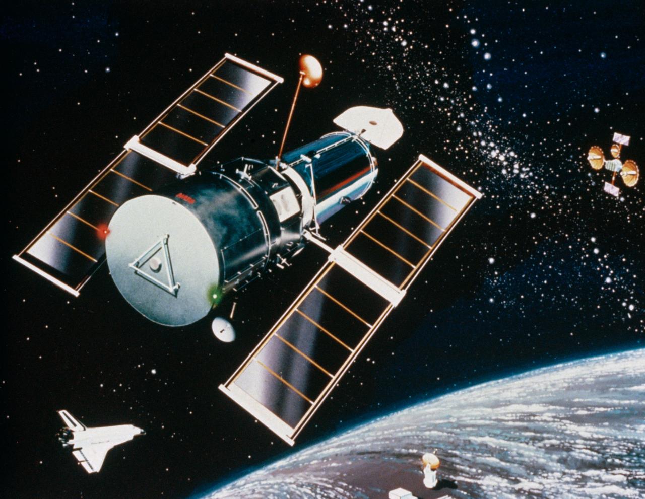
Artist concept shows the Hubble Space Telescope (HST) placed in orbit above the Earth's distorting layer of atmosphere by Discovery, Orbiter Vehicle (OV) 103, during mission STS-31. Tracking and data relay satellite (TDRS) is visible in the background and ground station is visible below on the Earth's surface. HST is the first of the great observatories to go into service and one of NASA's highest priority scientific spacecraft. Capable of observing in both visible and ultraviolet wavelengths, HST has been termed the most important scientific instrument ever designed for use on orbit. It will literally be able to look back in time, observing the universe as it existed early in its lifetime and providing information on how matter has evolved over the eons. The largest scientific payload ever built, the 12 1/2-ton, 43-foot HST was developed by Lockheed Missiles & Space Company, spacecraft prime contractor, and Perkin-Elmer Corporation, prime contractor for the optical assembly. The European Space Agency (ESA) furnished the power generating solar array and one of the system's five major instruments. Marshall Space Flight Center (MSFC) manages the HST project; Goddard Space Flight Center (GSFC) will be responsible, when the spacecraft is in orbit, for controlling the telescope and processing the images and instrument data returns.
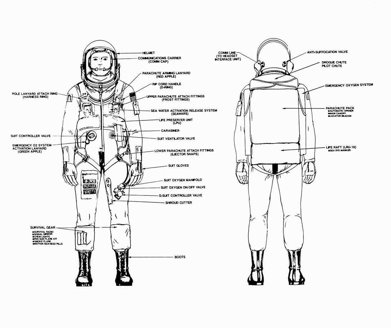
Line drawings illustrate the front and back of the space shuttle launch and entry suit (LES) and labels identify various components. LES was designed for STS-26, the return to flight mission, and subsequent missions. Included in the crew escape system (CES) package are launch and entry helmet (LEH) with communications carrier (COMM CAP), parachute pack and harness, life preserver unit (LPU), life raft unit (LRU), LES gloves, suit oxygen manifold and valves, boots, and survival gear. Details of larger components are also identified.
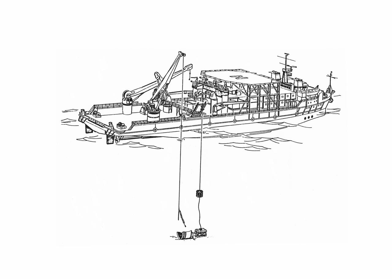
S86-30088 (March 1986) --- Salvage operations offshore of Kennedy Space Center, are depicted in this artist’s concept showing a grapple and recovery fixture (left) being directed through the use of a remote video system suspended from the recovery ship. Photo credit: NASA
S93-48826 (November 1993) --- This artist's rendition of the 1993 Hubble Space Telescope (HST) servicing mission shows astronauts installing the new Wide Field/Planetary Camera (WF/PC 2). The instruments to replace the original camera and contains corrective optics that compensate for the telescope's flawed primary mirror. During the 11-plus day mission, astronauts are also scheduled to install the Corrective Optics Space Telescope Axial Replacement (COSTAR) -- an optics package that focuses and routes light to the other three instruments aboard the observatory -- a new set of solar array panels, and other hardware and components. The artwork was done for JPL by Paul Hudson.
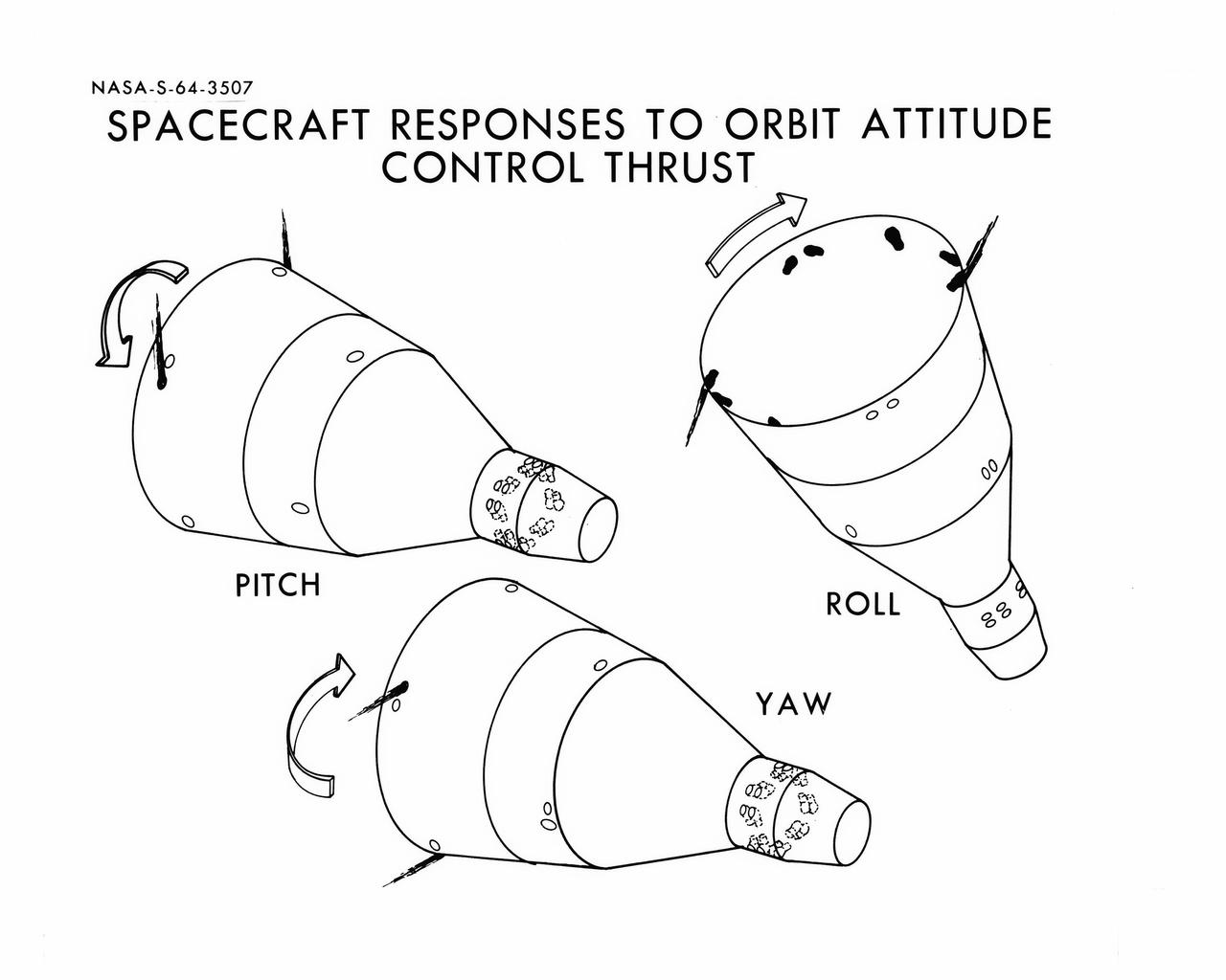
S64-03507 (1964) --- Diagrams shows Gemini spacecraft responses to orbital attitude systems's thrusters. Firing of appropriate combination of the thrusters cause pitch, roll and yaw.
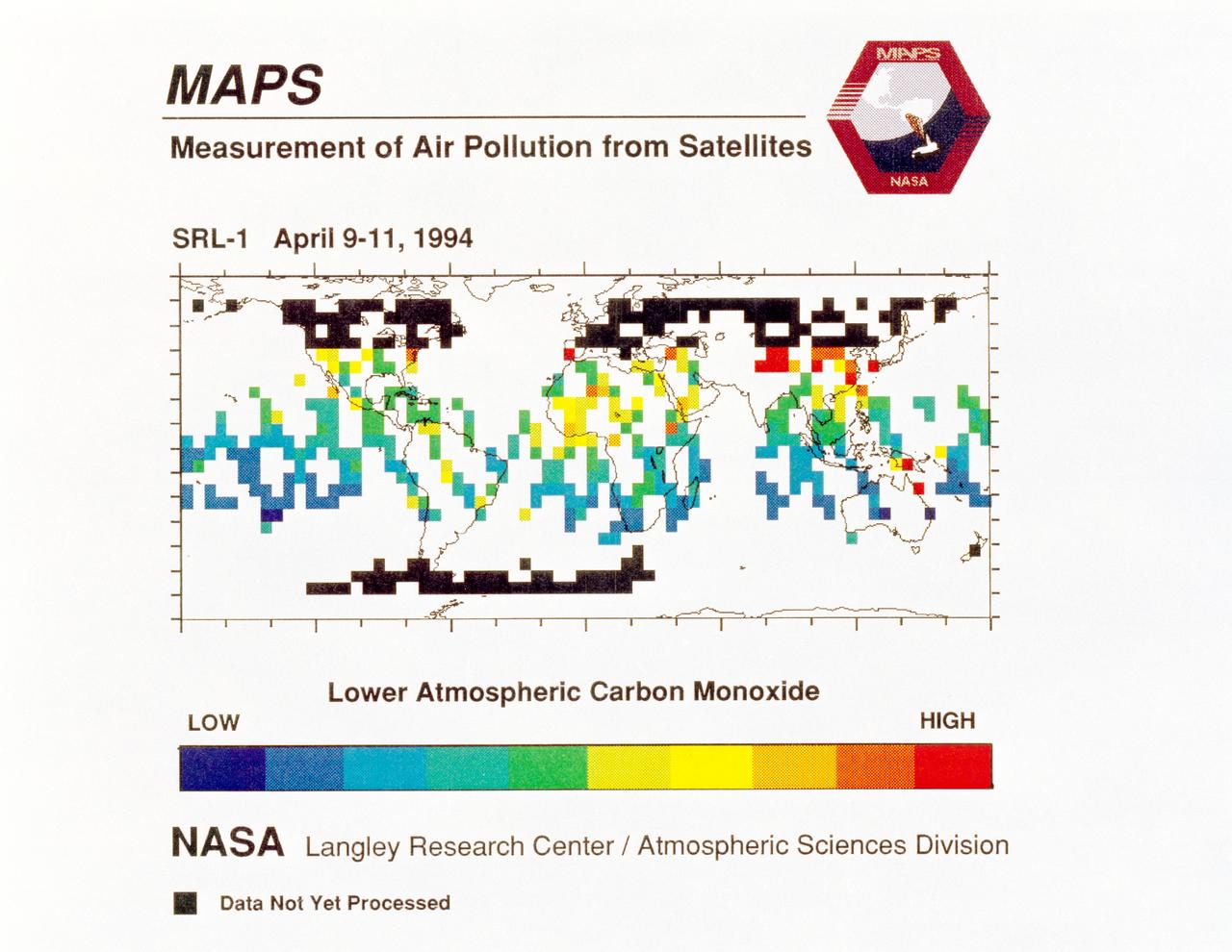
STS059-S-040 (12 April 1994) --- STS-59's MAPS (Measurement of Air Pollution from Satellites) experiment is sending real-time data that provides the most comprehensive view of carbon monoxide concentrations on Earth ever recorded. This computer image shows a summary of "quick look" data obtained by the MAPS instrument during its first days of operations as part of the Space Shuttle Endeavour's SRL-1 payload. This data will be processed using more sophisticated techniques following the flight. The color red indicates areas with the highest levels of carbon monoxide. These Northern Hemisphere springtime carbon monoxide values are generally significantly higher than the values found in the Southern Hemisphere. This is in direct contrast to the data obtained by the MAPS experiment during November 1981 and October 1984, i.e. during Northern Hemisphere fall. The astronauts aboard Endeavour have seen fires in most of the areas showing higher carbon monoxide values (China, Eastern Australia, and equatorial Africa). The relationship between the observed fires and the higher carbon monoxide values will be investigated following SRL-1 by combining the MAPS data with meteorological data, surface imagery, and Space Shuttle hand-held photographs. By the end of SRL-1, MAPS will have acquired data over most of the globe between 57 degrees north and 57 degrees south latitudes. The entire data set will be carefully analyzed using sophisticated post-flight data processing techniques. The data will then be applied in a variety of scientific studies concerning chemistry and transport processes in the atmosphere. The MAPS experiment measures the carbon monoxide in the lower atmosphere. This gas is produced both as a result of natural processes and as a result of human activities. The primary human resources of carbon monoxide are automobiles and industry and the burning of plant materials. The primary natural source is the interaction of sunlight with naturally occurring ozone and water vapor. The strength of all of these sources changes seasonally.
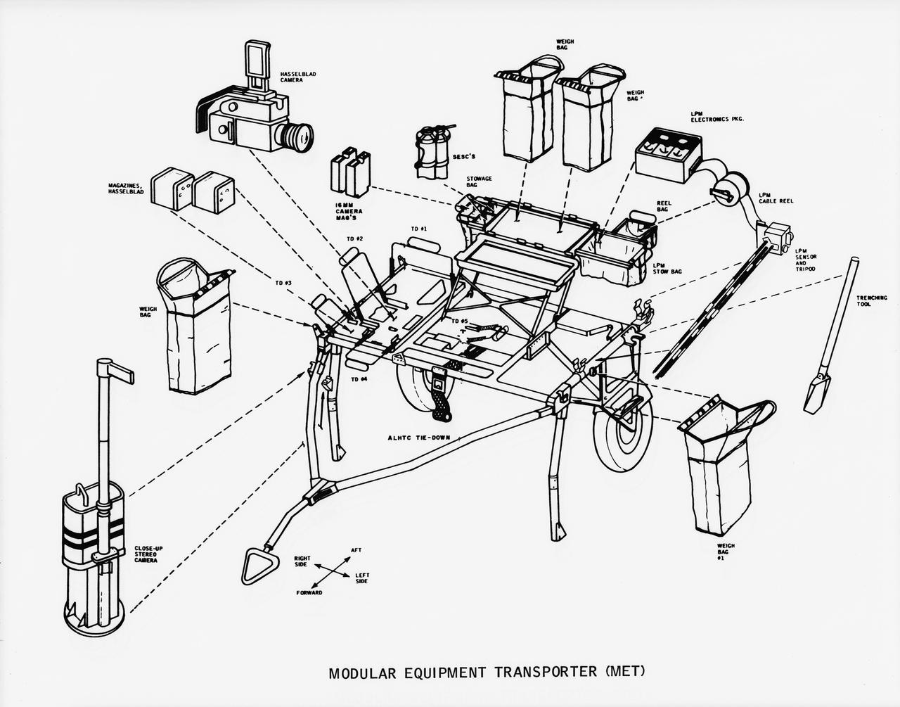
S70-50762 (November 1970) --- A line drawing illustrating layout view of the modular equipment transporter (MET) and its equipment. A MET (or Rickshaw, as it has been nicknamed) will be used on the lunar surface for the first time during the Apollo 14 lunar landing mission. The Rickshaw will serve as a portable workbench with a place for the Apollo lunar hand tools (ALHT) and their carrier, three cameras, two sample container bags, a special environment sample container (SESC), a lunar portable magnetometer (LPM) and spare film magazines.
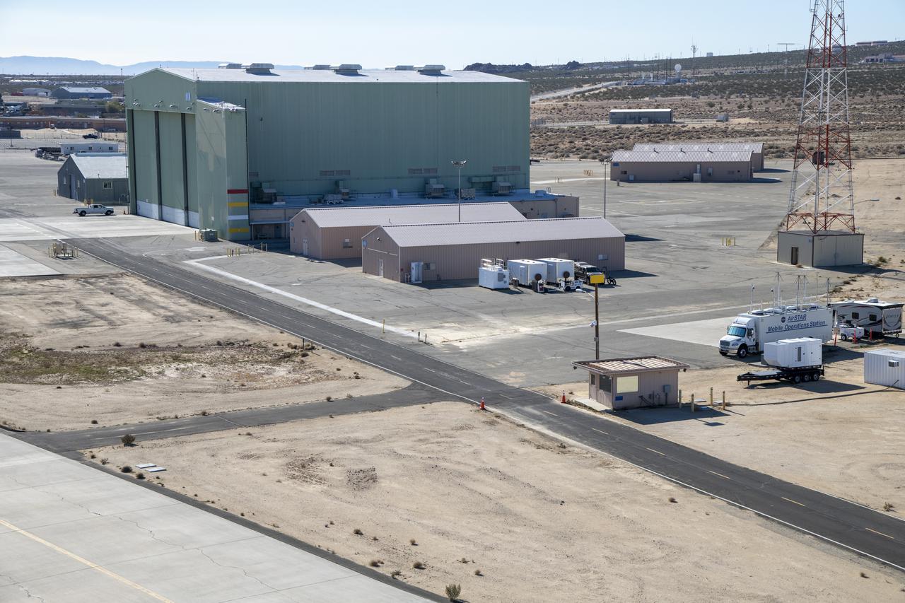
An aerial image taken by one of NASA’s photographers during recent helicopter flights shows a view of the building 4833 structure and the mobile operating facility at NASA’s Armstrong Flight Research Center in Edwards, California. NASA’s Advanced Air Mobility National Campaign uses the mobile operations facility vehicle shown in the lower right corner during test operations. The red, yellow, and white building markings applied to building 4833 are used to provide visual aids to the pilot during handling qualities testing used to research advanced air mobility flight requirements.
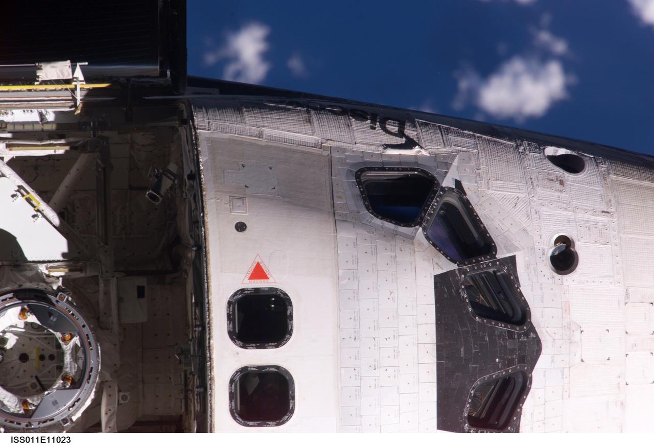
ISS011-E-11023 (28 July 2005) --- View of the Space Shuttle Discovery's crew cabin and the Orbiter Docking System (ODS), photographed as part of the survey sequence performed by the Expedition 11 crew during the STS-114 R-Bar Pitch Maneuver on Flight Day 3. This picture was used by Steve M. Poulos, Jr. Manager, Space Shuttle Vehicle Engineering Office, as one of his visual aids in a July 28, 2005 press conference in the Teague Auditorium at the Johnson Space Center. Poulos pointed out a raised area of thermal blanket material just below a window on the commander's (port) side of the cabin.
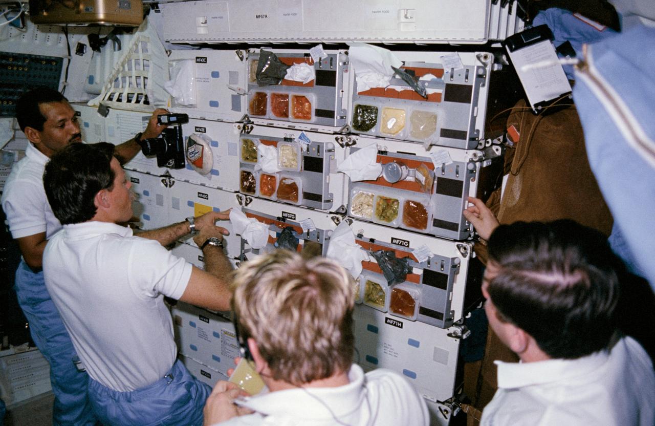
61C-14-015 (12-18 Jan. 1986) --- Astronauts Charles F. Bolden, STS-61C pilot; Robert L. Gibson, commander; George D. Nelson, mission specialist, and payload specialist Robert J. Cenker (RCA) queue at "chow line" on middeck of the space shuttle Columbia. Others onboard for the week-long mission were astronauts Steven A. Hawley and Franklin R. Chang-Diaz, mission specialists; and U.S. Representative Bill Nelson (Democrat - Florida). This photo was used as one of the visual aids at the crew's press conference on Jan. 23, 1986.
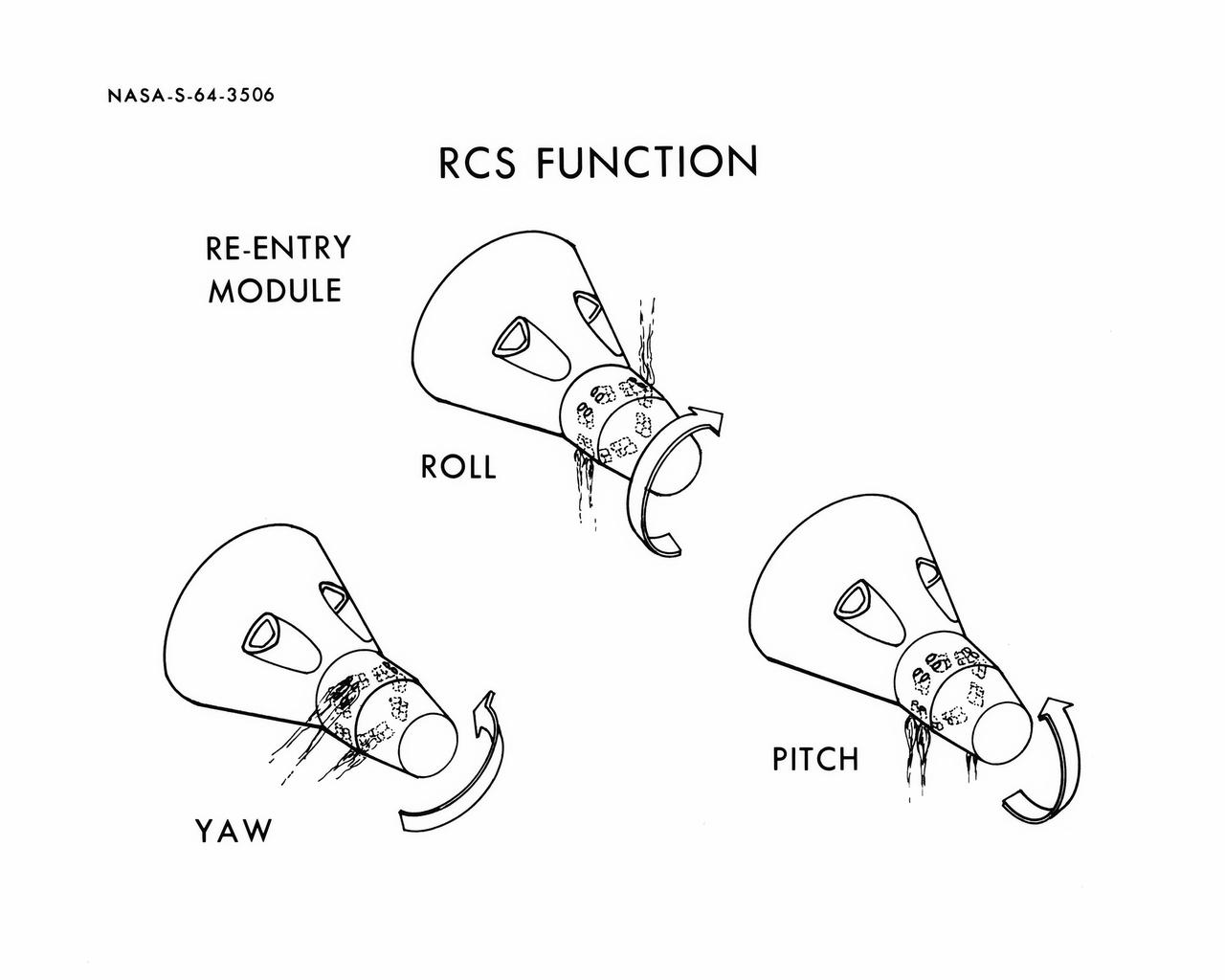
S64-03506 (1964) --- Diagrams shows Gemini spacecraft functions of the thrusters in the Gemini spacecraft's re-entry control system. Thrusters may be fired in various combinations to cause yaw, roll and pitch.
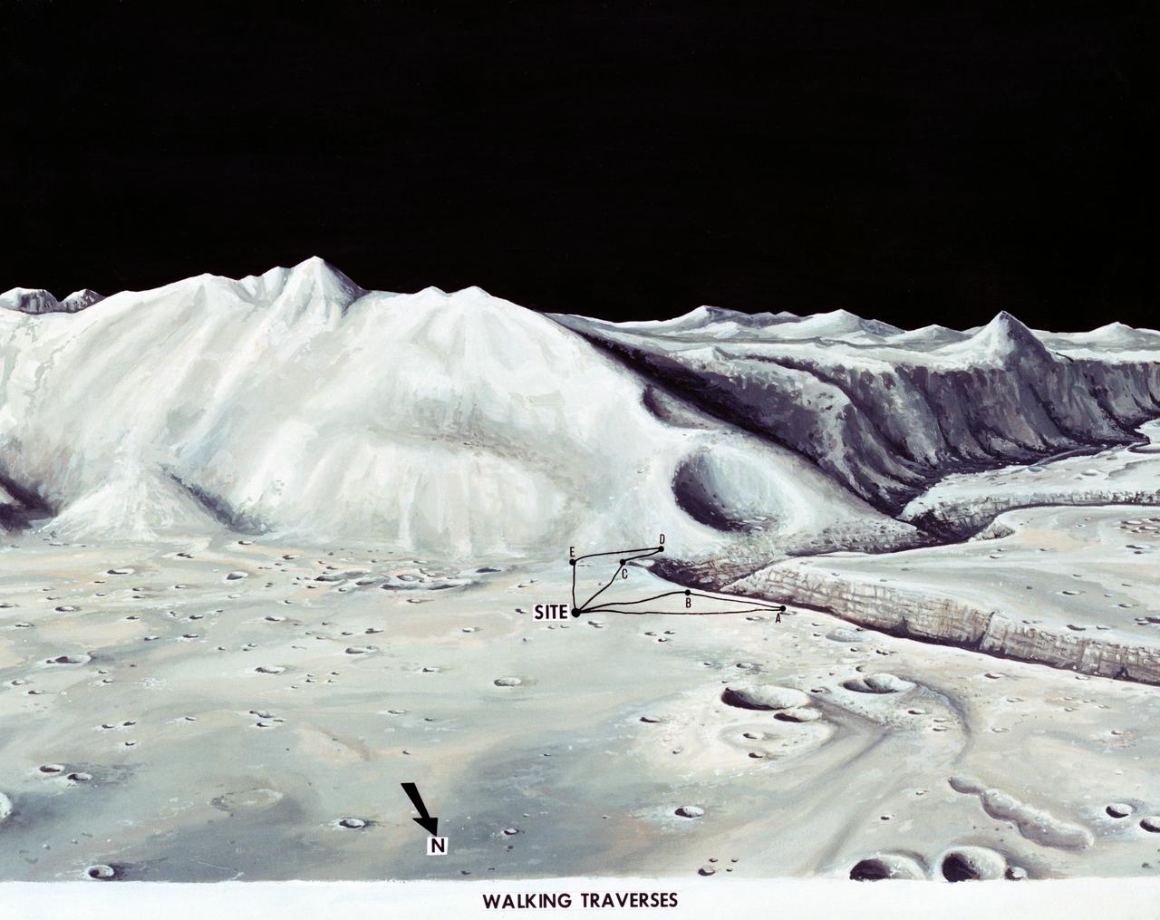
S71-33432 (1 July 1971) --- These alternative traverses can be carried out on foot. They will be used if the Lunar Roving Vehicle (LRV) becomes inoperative. This artist's concept showing part of the Hadley Rille and several of the Apennine Mountains was excerpted from "On the Moon with Apollo 15: A Guidebook to the Hadley-Apennine Region," by Gene Simmons. Artwork by Jerry Elmore.
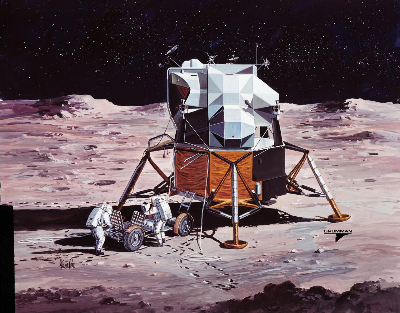
S71-38189 (26 June 1971) --- An artist's concept showing the final steps of readying the Apollo 15 Lunar Roving Vehicle (LRV) or Rover 1 for mobility on the lunar surface. Performing the last few LRV deployment tasks here are, left to right, astronauts James B. Irwin, lunar module pilot, and David R. Scott, commander. More specifically the tasks depicted here include the setting up of the seats and the total releasing of the LRV from the LM. (This is the fourth in a series of four Grumman Aerospace Corporation artist's concepts telling the lunar surface LRV deployment story for Apollo 15).
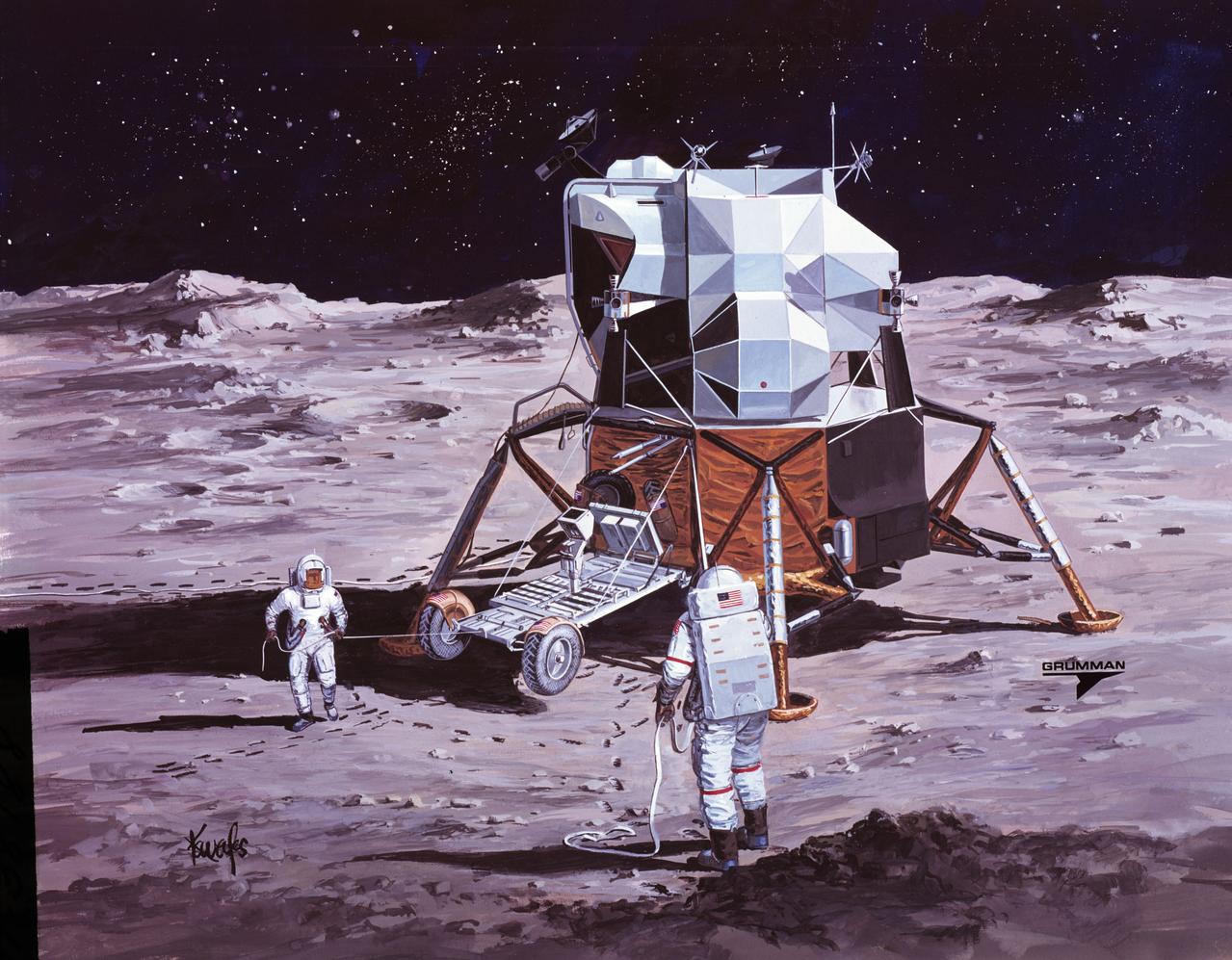
S71-38188 (26 June 1971) --- An artist's concept showing the Apollo 15 mission commander and the lunar module pilot performing deployment of the Lunar Roving Vehicle (LRV) on the lunar surface. The figure on the left represents astronaut James B. Irwin, lunar module pilot, who here is maintaining a constant pull on the deployment cable to help the LRV unfold, while astronaut David R. Scott (right), commander, pulls the tapes that lower the LRV to the surface. (This is the third in a series of Grumman Aerospace Corporation artist's concepts telling the lunar surface LRV deployment story of the Apollo 15 mission).
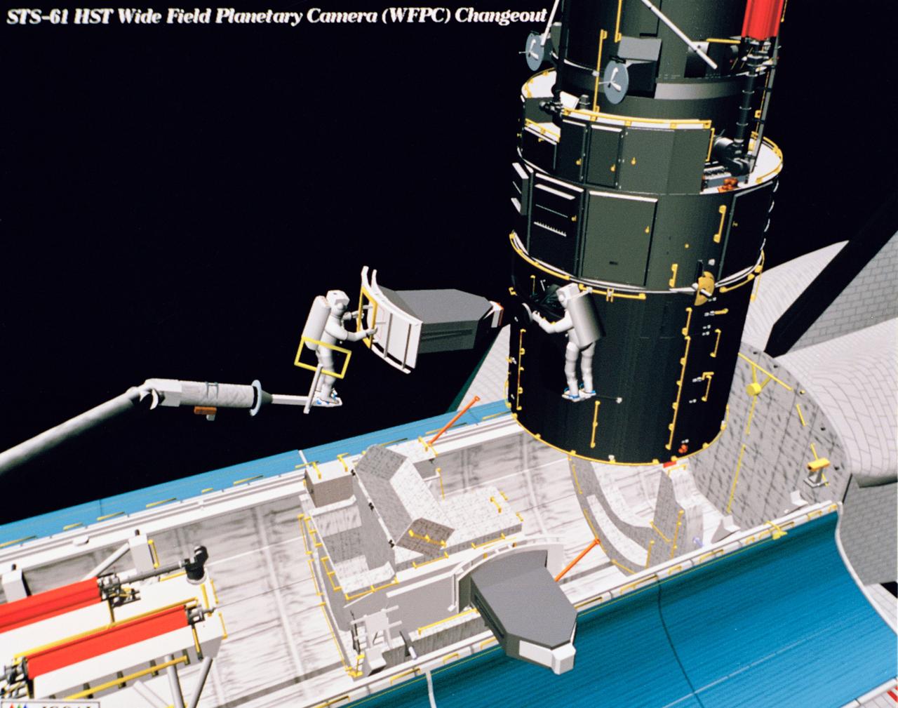
Computer generated scenes depicting the Hubble Space Telescope capture and a sequence of planned events on the planned extravehicular activity (EVA). Scenes include the Remote Manipulator System (RMS) arm assisting two astronauts changing out the Wide Field/Planetary Camera (WF/PC) (48699); RMS arm assisting in the temporary mating of the orbiting telescope to the flight support system in Endeavour's cargo bay (48700); Endeavour's RMS arm assisting in the "capture" of the orbiting telescope (48701); Two astronauts changing out the telescope's coprocessor (48702); RMS arm assistign two astronauts replacing one of the telescope's electronic control units (48703); RMS assisting two astronauts replacing the fuse plugs on the telescope's Power Distribution Unit (PDU) (48704); The telescope's High Resolution Spectrograph (HRS) kit is depicted in this scene (48705); Two astronauts during the removal of the high speed photometer and the installation of the COSTAR instrument (48706); Two astronauts, standing on the RMS, during installation of one of the Magnetic Sensing System (MSS) (48707); High angle view of the orbiting Space Shuttle Endeavour with its cargo bay doors open, revealing the bay's pre-capture configuration. Seen are, from the left, the Solar Array Carrier, the ORU Carrier and the flight support system (48708); Two astronauts performing the replacement of HST's Rate Sensor Units (RSU) (48709); The RMS arm assisting two astronauts with the replacement of the telescope's solar array panels (48710); Two astronauts replacing the telescope's Solar Array Drive Electronics (SADE) (48711).

On June 15, NASA's Swift caught the onset of a rare X-ray outburst from a stellar-mass black hole in the binary system V404 Cygni. Astronomers around the world are watching the event. In this system, a stream of gas from a star much like the sun flows toward a 10 solar mass black hole. Instead of spiraling toward the black hole, the gas accumulates in an accretion disk around it. Every couple of decades, the disk switches into a state that sends the gas rushing inward, starting a new outburst. Read more: <a href="http://www.nasa.gov/feature/goddard/nasa-missions-monitor-a-waking-black-hole" rel="nofollow">www.nasa.gov/feature/goddard/nasa-missions-monitor-a-waki...</a> Credits: NASA's Goddard Space Flight Center Download this video in HD formats from NASA Goddard's Scientific Visualization Studio <a href="http://svs.gsfc.nasa.gov/cgi-bin/details.cgi?aid=11110" rel="nofollow">svs.gsfc.nasa.gov/cgi-bin/details.cgi?aid=11110</a>
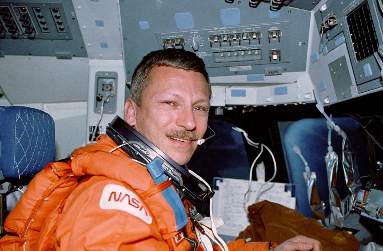
STS037-13-036 (5-11 April 1991) --- Astronaut Steven R. Nagel talks to ground controllers from the commander's station on the space shuttle Atlantis. He is wearing the special partial pressure suit used by space shuttle crew members for ascent and entry phases. Nagel, mission commander, and four other astronauts spent six days in space during which they readied the Gamma Ray Observatory (GRO) for deployment, released it into space, tested possible Space Station Freedom translation aid devices, conducted experiments, took photographs and performed other duties. This frame was taken with a 35mm camera. This was one of the visuals used by the crew members during their April 19 Post Flight Press Conference (PFPC) at the Johnson Space Center (JSC). Photo credit: NASA
![Multiple exposure of Gemini rendezvous docking simulator. Francis B. Smith wrote in his paper "Simulators for Manned Space Research," "The rendezvous and docking operation of the Gemini spacecraft with the Agena and of the Apollo Command Module with the Lunar Excursion Module have been the subject of simulator studies for several years. [This figure] illustrates the Gemini-Agena rendezvous docking simulator at Langley. The Gemini spacecraft was supported in a gimbal system by an overhead crane and gantry arrangement which provided 6 degrees of freedom - roll, pitch, yaw, and translation in any direction - all controllable by the astronaut in the spacecraft. Here again the controls fed into a computer which in turn provided an input to the servos driving the spacecraft so that it responded to control motions in a manner which accurately simulated the Gemini spacecraft." A.W. Vogeley further described the simulator in his paper "Discussion of Existing and Planned Simulators For Space Research," "Docking operations are considered to start when the pilot first can discern vehicle target size and aspect and terminate, of course, when soft contact is made. ... This facility enables simulation of the docking operation from a distance of 200 feet to actual contact with the target. A full-scale mock-up of the target vehicle is suspended near one end of the track. ... On [the Agena target] we have mounted the actual Agena docking mechanism and also various types of visual aids. We have been able to devise visual aids which have made it possible to accomplish nighttime docking with as much success as daytime docking." -- Published in Barton C. Hacker and James M. Grimwood, On the Shoulders of Titans: A History of Project Gemini, NASA SP-4203; Francis B. Smith, "Simulators for Manned Space Research," Paper presented at the 1966 IEEE International convention, March 21-25, 1966; A.W. Vogeley, "Discussion of Existing and Planned Simulators For Space Research," Paper presented at the Conference on the Role of Simulation in Space Technology, August 17-21, 1964.](https://images-assets.nasa.gov/image/LRC-1963-B701_P-08973/LRC-1963-B701_P-08973~medium.jpg)
Multiple exposure of Gemini rendezvous docking simulator. Francis B. Smith wrote in his paper "Simulators for Manned Space Research," "The rendezvous and docking operation of the Gemini spacecraft with the Agena and of the Apollo Command Module with the Lunar Excursion Module have been the subject of simulator studies for several years. [This figure] illustrates the Gemini-Agena rendezvous docking simulator at Langley. The Gemini spacecraft was supported in a gimbal system by an overhead crane and gantry arrangement which provided 6 degrees of freedom - roll, pitch, yaw, and translation in any direction - all controllable by the astronaut in the spacecraft. Here again the controls fed into a computer which in turn provided an input to the servos driving the spacecraft so that it responded to control motions in a manner which accurately simulated the Gemini spacecraft." A.W. Vogeley further described the simulator in his paper "Discussion of Existing and Planned Simulators For Space Research," "Docking operations are considered to start when the pilot first can discern vehicle target size and aspect and terminate, of course, when soft contact is made. ... This facility enables simulation of the docking operation from a distance of 200 feet to actual contact with the target. A full-scale mock-up of the target vehicle is suspended near one end of the track. ... On [the Agena target] we have mounted the actual Agena docking mechanism and also various types of visual aids. We have been able to devise visual aids which have made it possible to accomplish nighttime docking with as much success as daytime docking." -- Published in Barton C. Hacker and James M. Grimwood, On the Shoulders of Titans: A History of Project Gemini, NASA SP-4203; Francis B. Smith, "Simulators for Manned Space Research," Paper presented at the 1966 IEEE International convention, March 21-25, 1966; A.W. Vogeley, "Discussion of Existing and Planned Simulators For Space Research," Paper presented at the Conference on the Role of Simulation in Space Technology, August 17-21, 1964.
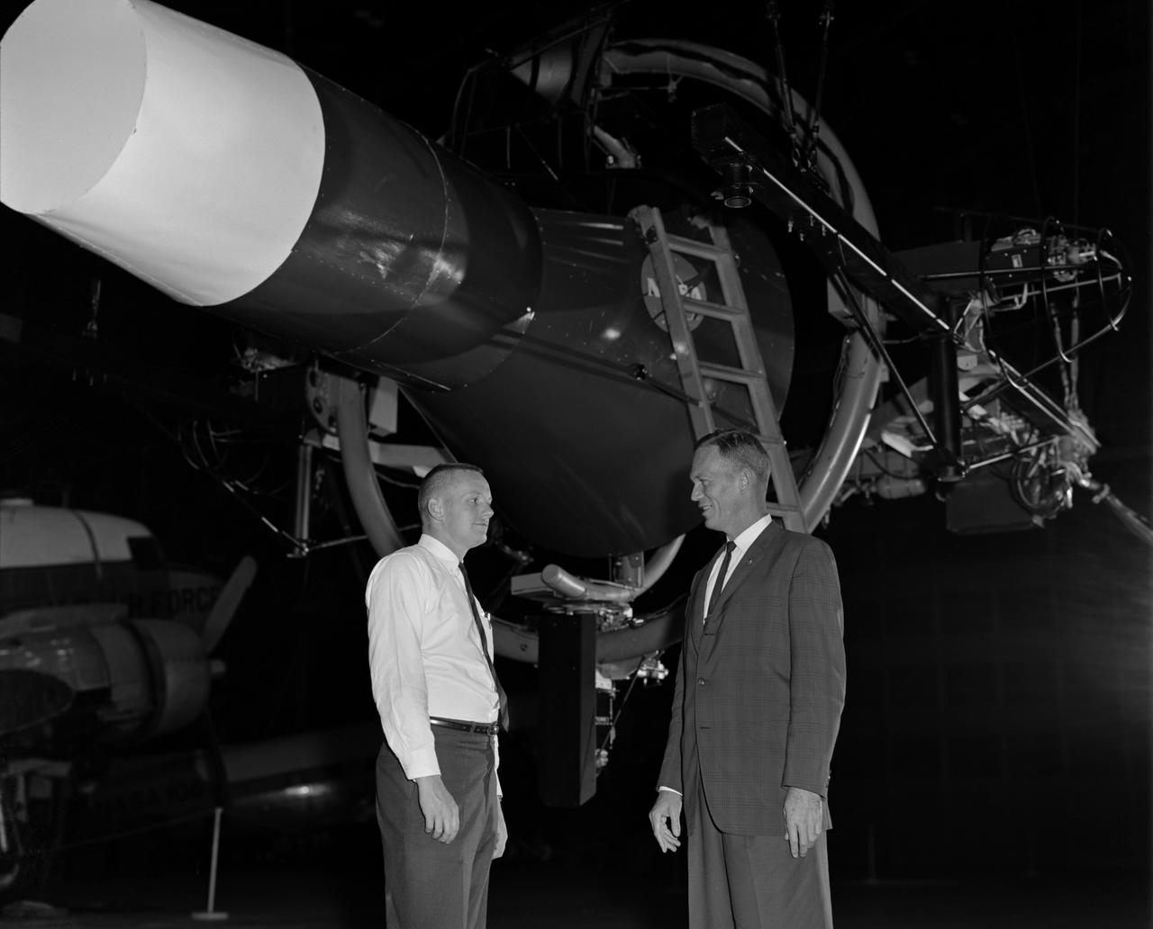
Astronaut Neil Armstrong (left) was one of 14 astronauts, 8 NASA test pilots, and 2 McDonnell test pilots who took part in simulator studies. Armstrong was the first astronaut to participate (November 6, 1963). A.W. Vogeley described the simulator in his paper "Discussion of Existing and Planned Simulators For Space Research," "Many of the astronauts have flown this simulator in support of the Gemini studies and they, without exception, appreciated the realism of the visual scene. The simulator has also been used in the development of pilot techniques to handle certain jet malfunctions in order that aborts could be avoided. In these situations large attitude changes are sometimes necessary and the false motion cues that were generated due to earth gravity were somewhat objectionable; however, the pilots were readily able to overlook these false motion cues in favor of the visual realism." Roy F. Brissenden, noted in his paper "Initial Operations with Langley's Rendezvous Docking Facility," "The basic Gemini control studies developed the necessary techniques and demonstrated the ability of human pilots to perform final space docking with the specified Gemini-Agena systems using only visual references. ... Results... showed that trained astronauts can effect the docking with direct acceleration control and even with jet malfunctions as long as good visual conditions exist.... Probably more important than data results was the early confidence that the astronauts themselves gained in their ability to perform the maneuver in the ultimate flight mission." Francis B. Smith, noted in his paper "Simulators for Manned Space Research," "Some major areas of interest in these flights were fuel requirements, docking accuracies, the development of visual aids to assist alignment of the vehicles, and investigation of alternate control techniques with partial failure modes. However, the familiarization and confidence developed by the astronaut through flying and safely docking the simulator during these tests was one of the major contributions. For example, it was found that fuel used in docking from 200 feet typically dropped from about 20 pounds to 7 pounds after an astronaut had made a few training flights." -- Published in Barton C. Hacker and James M. Grimwood, On the Shoulders of Titans: A History of Project Gemini, NASA SP-4203; A.W. Vogeley, "Discussion of Existing and Planned Simulators For Space Research," Paper presented at the Conference on the Role of Simulation in Space Technology, August 17-21, 1964; Roy F. Brissenden, "Initial Operations with Langley's Rendezvous Docking Facility," Langley Working Paper, LWP-21, 1964; Francis B. Smith, "Simulators for Manned Space Research," Paper presented at the 1966 IEEE International convention, March 21-25, 1966.
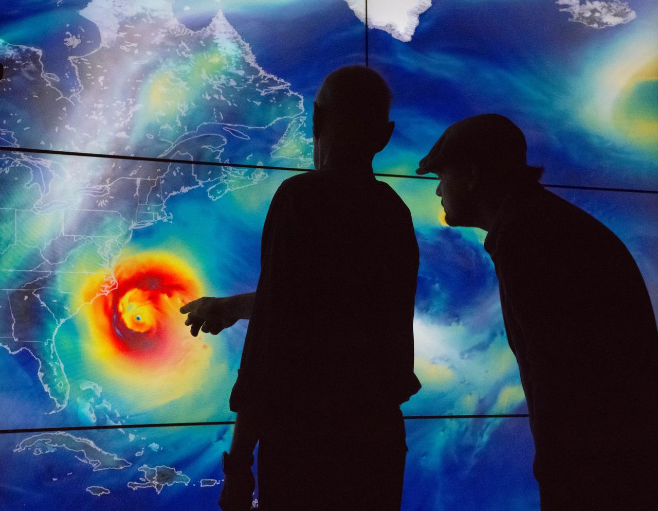
Academy Award®- winning actor and environmental activist Leonardo DiCaprio visited NASA’s Goddard Space Flight Center in Greenbelt, Maryland on Saturday, April 23, 2016. During his visit, Mr. DiCaprio interviewed Dr. Piers Sellers, an Earth scientist, former astronaut and current deputy director of Goddard’s Sciences and Exploration Directorate. The two discussed the different missions NASA has underway to study changes in the Earth’s atmosphere, water and land masses for a climate change documentary that Mr. DiCaprio has in production. Using a wall-size, high-definition display system that shows visual representations based on actual science data, Mr. DiCaprio and Dr. Sellers discussed data results from NASA’s fleet of satellites in Earth’s orbit. The visual shows Hurricane Sandy. The visual uses data from Goddard Earth Observing System Model, Version 5 (GEOS-5) to simulate surface wind speeds across the Atlantic during Sandy’s lifecycle. <a href="http://svs.gsfc.nasa.gov/cgi-bin/details.cgi?aid=30465" rel="nofollow">svs.gsfc.nasa.gov/cgi-bin/details.cgi?aid=30465</a> During his visit, Mr. DiCaprio also visited the facility holding NASA’s James Webb Space Telescope that is being developed as a large infrared telescope with a 6.5-meter primary mirror. The telescope will be launched on an Ariane 5 rocket from French Guiana in October of 2018, and will be a premier observatory of the next decade, serving thousands of astronomers worldwide. Credit: NASA/Goddard/Rebecca Roth <b><a href="http://www.nasa.gov/audience/formedia/features/MP_Photo_Guidelines.html" rel="nofollow">NASA image use policy.</a></b> <b><a href="http://www.nasa.gov/centers/goddard/home/index.html" rel="nofollow">NASA Goddard Space Flight Center</a></b> enables NASA’s mission through four scientific endeavors: Earth Science, Heliophysics, Solar System Exploration, and Astrophysics. Goddard plays a leading role in NASA’s accomplishments by contributing compelling scientific knowledge to advance the Agency’s mission. <b>Follow us on <a href="http://twitter.com/NASAGoddardPix" rel="nofollow">Twitter</a></b> <b>Like us on <a href="http://www.facebook.com/pages/Greenbelt-MD/NASA-Goddard/395013845897?ref=tsd" rel="nofollow">Facebook</a></b> <b>Find us on <a href="http://instagrid.me/nasagoddard/?vm=grid" rel="nofollow">Instagram</a></b>
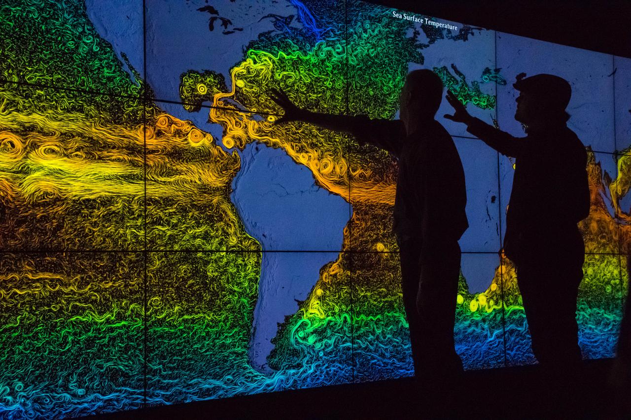
Academy Award®- winning actor and environmental activist Leonardo DiCaprio visited NASA’s Goddard Space Flight Center in Greenbelt, Maryland on Saturday, April 23, 2016. During his visit, Mr. DiCaprio interviewed Dr. Piers Sellers, an Earth scientist, former astronaut and current deputy director of Goddard’s Sciences and Exploration Directorate. The two discussed the different missions NASA has underway to study changes in the Earth’s atmosphere, water and land masses for a climate change documentary that Mr. DiCaprio has in production. Using a wall-size, high-definition display system that shows visual representations based on actual science data, Mr. DiCaprio and Dr. Sellers discussed data results from NASA’s fleet of satellites in Earth’s orbit. The background image showing global sea surface circulation colored by temperature where reds are warm areas (32 degrees Celsius) and blues are cold regions (0 degrees Celsius). The data used for this visual is a joint MIT/JPL project called Estimating the Circulation and Climate of the Ocean, Phase II (ECCO2). For more info on this visual, <a href="http://svs.gsfc.nasa.gov/cgi-bin/details.cgi?aid=3912" rel="nofollow">svs.gsfc.nasa.gov/cgi-bin/details.cgi?aid=3912</a> During his visit, Mr. DiCaprio also visited the facility holding NASA’s James Webb Space Telescope that is being developed as a large infrared telescope with a 6.5-meter primary mirror. The telescope will be launched on an Ariane 5 rocket from French Guiana in October of 2018, and will be a premier observatory of the next decade, serving thousands of astronomers worldwide. Credit: NASA/Goddard/Rebecca Roth <b><a href="http://www.nasa.gov/audience/formedia/features/MP_Photo_Guidelines.html" rel="nofollow">NASA image use policy.</a></b> <b><a href="http://www.nasa.gov/centers/goddard/home/index.html" rel="nofollow">NASA Goddard Space Flight Center</a></b> enables NASA’s mission through four scientific endeavors: Earth Science, Heliophysics, Solar System Exploration, and Astrophysics. Goddard plays a leading role in NASA’s accomplishments by contributing compelling scientific knowledge to advance the Agency’s mission. <b>Follow us on <a href="http://twitter.com/NASAGoddardPix" rel="nofollow">Twitter</a></b> <b>Like us on <a href="http://www.facebook.com/pages/Greenbelt-MD/NASA-Goddard/395013845897?ref=tsd" rel="nofollow">Facebook</a></b> <b>Find us on <a href="http://instagrid.me/nasagoddard/?vm=grid" rel="nofollow">Instagram</a></b>
S71-16101 (January 1971) --- A Grumman Aerospace Corporation artist's concept of Apollo 14 crewmen, astronauts Alan B. Shepard Jr., commander, and Edgar D. Mitchell, lunar module pilot, as they set out on their first traverse. Shepard is pulling the Modularized Equipment Transporter (MET) which contains cameras, lunar sample bags, tools and other paraphernalia. Shepard has the Laser Ranging Retro-Reflector (LR-3) in his other hand. Mitchell is carrying the Apollo Lunar Surface Experiments Package (ALSEP) barbell mode.
S71-16574 (11 Jan. 1971) --- An artist's concept depicting the Apollo 14 Command and Service Modules (CSM) circling the moon as the Lunar Module (LM) heads toward a lunar landing. While astronaut Stuart A. Roosa, command module pilot, remains with the CSM in lunar orbit, astronauts Alan B. Shepard Jr., commander; and Edgar D. Mitchell, lunar module pilot, will descend in the LM to explore an area in the rugged Fra Mauro highlands.
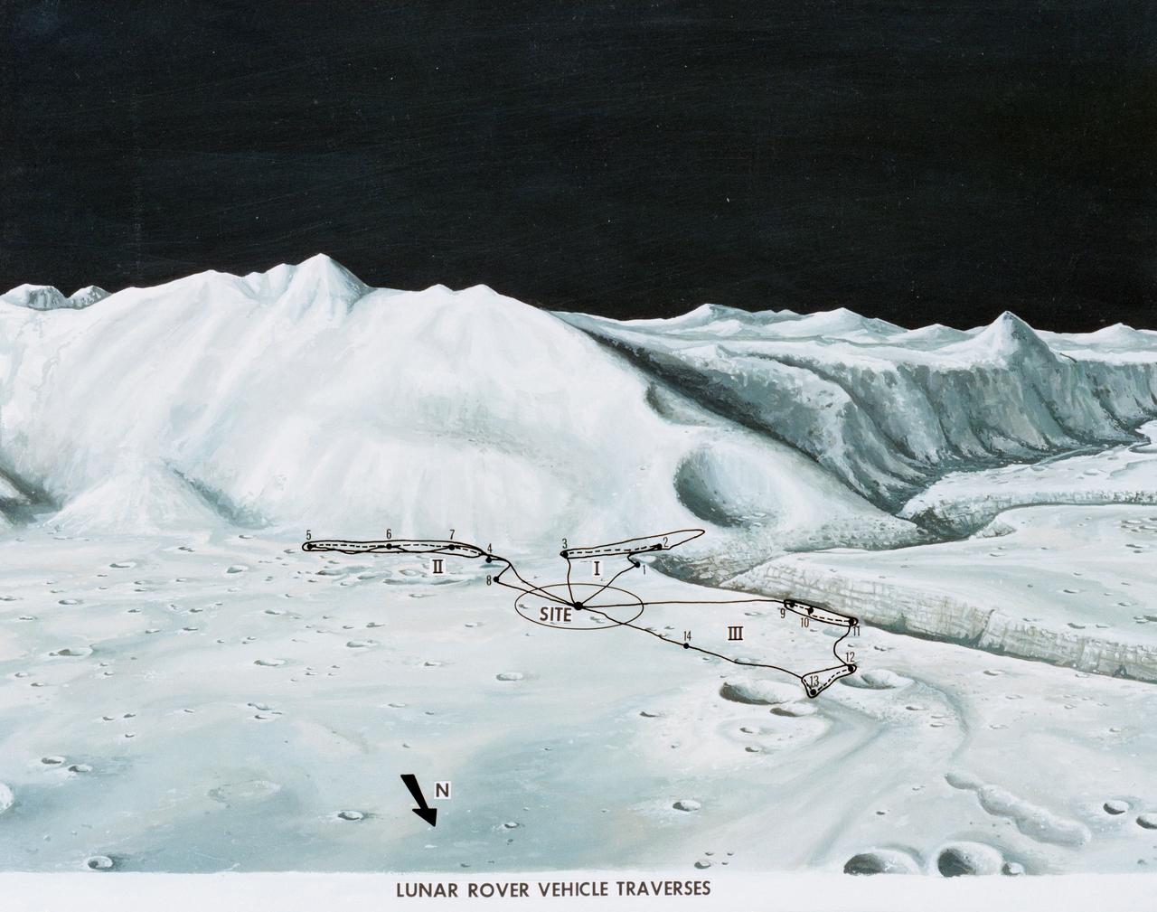
S71-33433 (1 July 1971) --- An artist's concept of the Hadley-Apennine landing site, depicting the traverses planned on the Apollo 15 lunar landing mission using the Lunar Roving Vehicle (LRV). The Roman numerals indicate the three periods of extravehicular activity (EVA). The Arabic numbers represent the station stops. This artist's concept was excerpted from "On the Moon with Apollo 15: A Guidebook to Hadley Rille and the Apennine Mountains," by Gene Simmons. The station stops indicated here are keyed to information given in the publication. Artwork by Jerry Elmore.
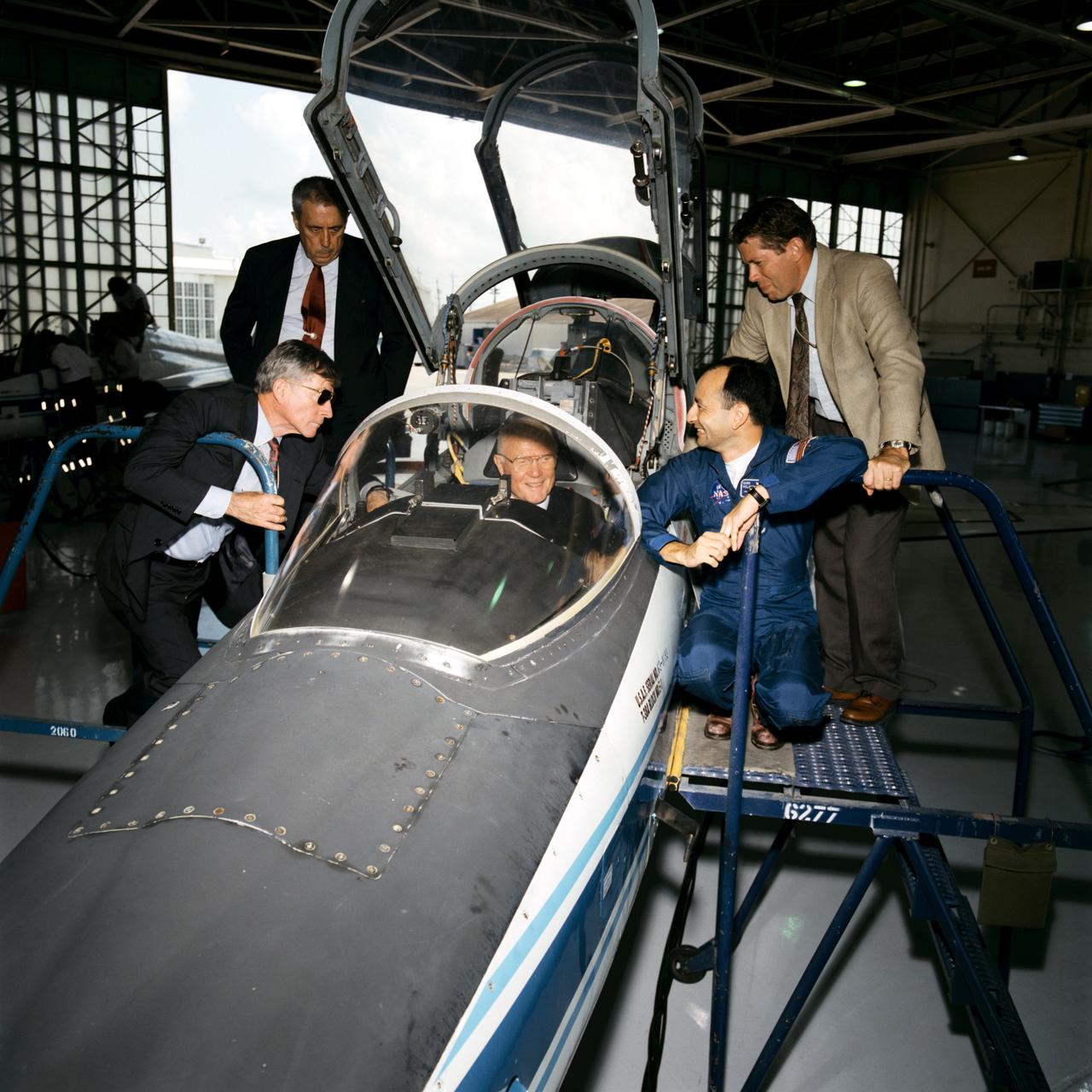
Senator John Glenn visit to Johnson Space Center (JSC). Views of Glenn sitting in cockpit of T-38 in Hangar 276 with John Young, George Abbey, David Leestma and Mark Polansky observing (11150). An engineer explains SPIFEX experiment hardware to Abby, Young and Glenn in Bldg 13 (11151, 11153). Glenn talks with astronaut Terrence T. Henricks and employees in Bldg 9C, Virtual reality lab (11152). Lunch in Bldg 17 Flight Crew support division with Dr. Ellen Baker, Robert "Hoot" Gibson and John Glenn (11154). Linda Godwin, Robert Cabana, Abbey, Young, Baker, Gibson and Glenn at lunch (11155). Astronaut Mark Lee shows Glenn and his aide how to use the virtural reality helmets (11156-7). Glenn shakes the hand of Franklin Chang-Diaz with his plasma rocket in the background in the Sonny Carter Training Facility (SCTF) (11158). Glenn in the Manipulator Development Facility (MDF) Remote Manipulator System (RMS) station mock-up in Bldg 9A with Abbey, Young and aide (11159, 11186). Glenn signs a book for Thomas D. Jones as Frederick Sturckow and Linda Godwin look on (11160). Glenn inside visual-vestibular trainer in Bldg 9B (11161). In conference room meeting with astronaut corps in Bldg 4S, Glenn shakes Robert Cabana's hand (11162). John Glenn and John Young pose for a group shot with Bldg 17 Food lab personnel (11163). Glenn thanks the food lab personnel (11164). Glenn visits Bldg 5 Fixed Base (FB) middeck simulator with astronauts Terrence Henricks and Mary Ellen Weber (11165). Glenn with Charles T. Bourland (11166). STS-70 crew Donald Thomas, Terrence Henricks, Mary Ellen Weber, Nancy Currie and Kevin Kregel with Glenn's advisor (11167). STS-70 crew Thomas, Henricks, Weber, Currie and Kregel with John Glenn (11175). Glenn with Thomas, Kregel, Weber, Henricks and trainer (11176-7). David J. Homan assists Glenn's aide with virtual reality goggles (11168) and Glenn (11174). John Young in Bldg 9C equilibrium trainer (11169). Glenn with Carl Walz in flight deck mock-up of MDF in Bldg 9NE (11170, 11187). Young, Abbey, aides, Glenn and Walz examine helium balloon in MDF (11171-2). Chang-Diaz shows Glenn's tour group the plasma rocket (11173). Glenn's presentation to astronaut corps (11178-81, 11184-5). Glenn is presented with framed picture of Sonny Carter Training Facility (SCTF) (11182) and framed picture of space station (11183).
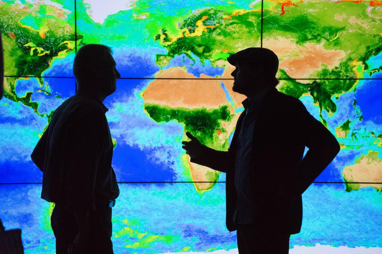
Academy Award®- winning actor and environmental activist Leonardo DiCaprio visited NASA’s Goddard Space Flight Center in Greenbelt, Maryland on Saturday, April 23, 2016. During his visit, Mr. DiCaprio interviewed Dr. Piers Sellers, an Earth scientist, former astronaut and current deputy director of Goddard’s Sciences and Exploration Directorate. The two discussed the different missions NASA has underway to study changes in the Earth’s atmosphere, water and land masses for a climate change documentary that Mr. DiCaprio has in production. Using a wall-size, high-definition display system that shows visual representations based on actual science data, Mr. DiCaprio and Dr. Sellers discussed data results from NASA’s fleet of satellites in Earth’s orbit. The background visual shows the biosphere with data from a NASA satellite instrument called the Sea-viewing Wide Field-of-View Sensor (SeaWiFS). <a href="http://svs.gsfc.nasa.gov/cgi-bin/details.cgi?aid=10704" rel="nofollow">svs.gsfc.nasa.gov/cgi-bin/details.cgi?aid=10704</a> During his visit, Mr. DiCaprio also visited the facility holding NASA’s James Webb Space Telescope that is being developed as a large infrared telescope with a 6.5-meter primary mirror. The telescope will be launched on an Ariane 5 rocket from French Guiana in October of 2018, and will be a premier observatory of the next decade, serving thousands of astronomers worldwide. Credit: NASA/Goddard/Rebecca Roth <b><a href="http://www.nasa.gov/audience/formedia/features/MP_Photo_Guidelines.html" rel="nofollow">NASA image use policy.</a></b> <b><a href="http://www.nasa.gov/centers/goddard/home/index.html" rel="nofollow">NASA Goddard Space Flight Center</a></b> enables NASA’s mission through four scientific endeavors: Earth Science, Heliophysics, Solar System Exploration, and Astrophysics. Goddard plays a leading role in NASA’s accomplishments by contributing compelling scientific knowledge to advance the Agency’s mission. <b>Follow us on <a href="http://twitter.com/NASAGoddardPix" rel="nofollow">Twitter</a></b> <b>Like us on <a href="http://www.facebook.com/pages/Greenbelt-MD/NASA-Goddard/395013845897?ref=tsd" rel="nofollow">Facebook</a></b> <b>Find us on <a href="http://instagrid.me/nasagoddard/?vm=grid" rel="nofollow">Instagram</a></b>
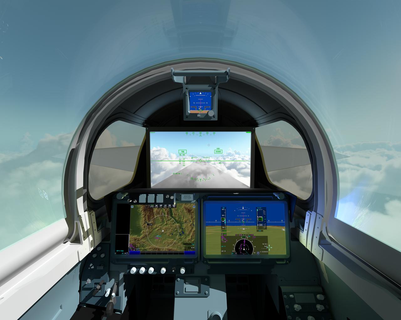
The pilot of NASAÕs X-59 Quiet SuperSonic Technology, or QueSST, aircraft will navigate the skies in a cockpit unlike any other. There wonÕt be a forward-facing window. ThatÕs right; itÕs actually a 4K monitor that serves as the central window and allows the pilot to safely see traffic in his or her flight path, and provides additional visual aids for airport approaches, landings and takeoffs. The 4K monitor, which is part of the aircraftÕs eXternal Visibility System, or XVS, displays stitched images from two cameras outside the aircraft combined with terrain data from an advanced computing system. The two portals and traditional canopy are real windows however, and help the pilot see the horizon. The displays below the XVS will provide a variety of aircraft systems and trajectory data for the pilot to safely fly. The XVS is one of several innovative solutions to help ensure the X-59Õs design shape reduces a sonic boom to a gentle thump heard by people on the ground. Though not intended to ever carry passengers, the X-59 boom-suppressing technology and community response data could help lift current bans on supersonic flight over land and enable a new generation of quiet supersonic commercial aircraft.
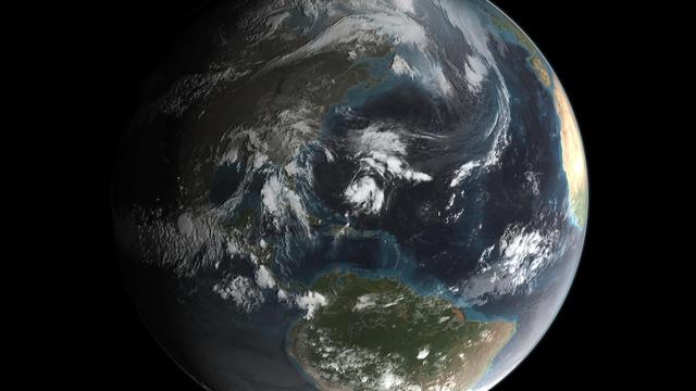
Joaquin became a tropical storm Monday evening (EDT) midway between the Bahamas and Bermuda and has now formed into Hurricane Joaquin, the 3rd of the season--the difference is Joaquin could impact the US East Coast. NASA's GPM satellite captured Joaquin Tuesday, September 29th at 21:39 UTC (5:39 pm EDT). Credit: NASA's Scientific Visualization Studio Data provided by the joint NASA/JAXA GPM mission. Download/read more: <a href="http://svs.gsfc.nasa.gov/cgi-bin/details.cgi?aid=4367" rel="nofollow">svs.gsfc.nasa.gov/cgi-bin/details.cgi?aid=4367</a> <b><a href="http://www.nasa.gov/audience/formedia/features/MP_Photo_Guidelines.html" rel="nofollow">NASA image use policy.</a></b> <b><a href="http://www.nasa.gov/centers/goddard/home/index.html" rel="nofollow">NASA Goddard Space Flight Center</a></b> enables NASA’s mission through four scientific endeavors: Earth Science, Heliophysics, Solar System Exploration, and Astrophysics. Goddard plays a leading role in NASA’s accomplishments by contributing compelling scientific knowledge to advance the Agency’s mission. <b>Follow us on <a href="http://twitter.com/NASAGoddardPix" rel="nofollow">Twitter</a></b> <b>Like us on <a href="http://www.facebook.com/pages/Greenbelt-MD/NASA-Goddard/395013845897?ref=tsd" rel="nofollow">Facebook</a></b> <b>Find us on <a href="http://instagrid.me/nasagoddard/?vm=grid" rel="nofollow">Instagram</a></b>

As the sun sets over the Arctic, the end of this year’s melt season is quickly approaching and the sea ice cover has already shrunk to the fourth lowest in the satellite record. With possibly some days of melting left, the sea ice extent could still drop to the second or third lowest on record. Arctic sea ice, which regulates the planet’s temperature by bouncing solar energy back to space, has been on a steep decline for the last two decades. This animation shows the evolution of Arctic sea ice in 2015, from its annual maximum wintertime extent, reached on February 25, to September 6. Credit: NASA Scientific Visualization Studio DOWNLOAD THIS VIDEO HERE: <a href="https://svs.gsfc.nasa.gov/cgi-bin/details.cgi?aid=11999" rel="nofollow">svs.gsfc.nasa.gov/cgi-bin/details.cgi?aid=11999</a> <b><a href="http://www.nasa.gov/audience/formedia/features/MP_Photo_Guidelines.html" rel="nofollow">NASA image use policy.</a></b> <b><a href="http://www.nasa.gov/centers/goddard/home/index.html" rel="nofollow">NASA Goddard Space Flight Center</a></b> enables NASA’s mission through four scientific endeavors: Earth Science, Heliophysics, Solar System Exploration, and Astrophysics. Goddard plays a leading role in NASA’s accomplishments by contributing compelling scientific knowledge to advance the Agency’s mission. <b>Follow us on <a href="http://twitter.com/NASAGoddardPix" rel="nofollow">Twitter</a></b> <b>Like us on <a href="http://www.facebook.com/pages/Greenbelt-MD/NASA-Goddard/395013845897?ref=tsd" rel="nofollow">Facebook</a></b> <b>Find us on <a href="http://instagrid.me/nasagoddard/?vm=grid" rel="nofollow">Instagram</a></b>
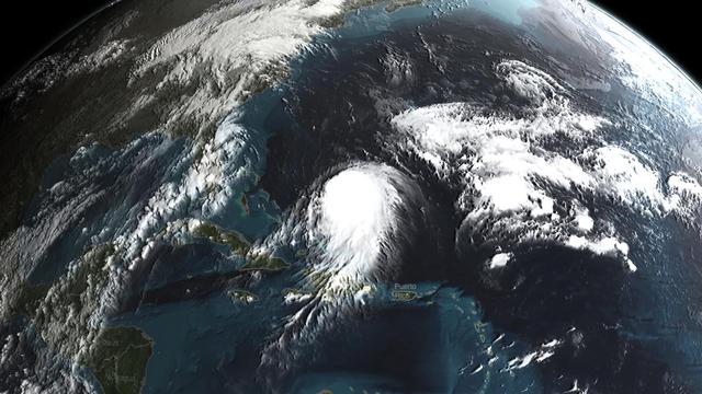
Joaquin became a tropical storm Monday evening (EDT) midway between the Bahamas and Bermuda and has now formed into Hurricane Joaquin, the 3rd of the season--the difference is Joaquin could impact the US East Coast. NASA's GPM satellite captured Joaquin Tuesday, September 29th at 21:39 UTC (5:39 pm EDT). Credit: NASA's Scientific Visualization Studio Data provided by the joint NASA/JAXA GPM mission. Download/read more: <a href="http://svs.gsfc.nasa.gov/cgi-bin/details.cgi?aid=4367" rel="nofollow">svs.gsfc.nasa.gov/cgi-bin/details.cgi?aid=4367</a> <b><a href="http://www.nasa.gov/audience/formedia/features/MP_Photo_Guidelines.html" rel="nofollow">NASA image use policy.</a></b> <b><a href="http://www.nasa.gov/centers/goddard/home/index.html" rel="nofollow">NASA Goddard Space Flight Center</a></b> enables NASA’s mission through four scientific endeavors: Earth Science, Heliophysics, Solar System Exploration, and Astrophysics. Goddard plays a leading role in NASA’s accomplishments by contributing compelling scientific knowledge to advance the Agency’s mission. <b>Follow us on <a href="http://twitter.com/NASAGoddardPix" rel="nofollow">Twitter</a></b> <b>Like us on <a href="http://www.facebook.com/pages/Greenbelt-MD/NASA-Goddard/395013845897?ref=tsd" rel="nofollow">Facebook</a></b> <b>Find us on <a href="http://instagrid.me/nasagoddard/?vm=grid" rel="nofollow">Instagram</a></b>
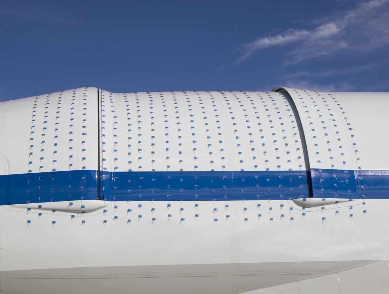
NASA's Stratospheric Observatory for Infrared Astronomy, or SOFIA, arrived at NASA's Dryden Flight Research Center at Edwards Air Force Base, Calif. on May 31, 2007. The heavily modified Boeing 747SP was ferried to Dryden from Waco, Texas, where L-3 Communications Integrated Systems installed a German-built 2.5-meter infrared telescope and made other major modifications over the past several years. SOFIA is scheduled to undergo installation and integration of mission systems and a multi-phase flight test program at Dryden over the next three years that is expected to lead to a full operational capability to conduct astronomy missions in about 2010. During its expected 20-year lifetime, SOFIA will be capable of "Great Observatory" class astronomical science, providing astronomers with access to the visible, infrared and sub-millimeter spectrum with optimized performance in the mid-infrared to sub-millimeter range.

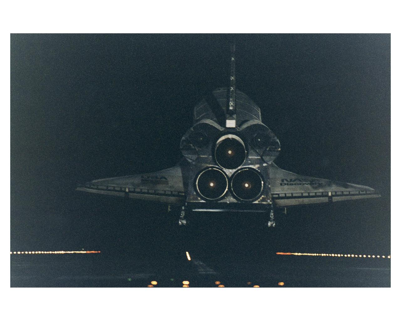
KENNEDY SPACE CENTER, Fla. -- Under the cover of darkness, the Space Shuttle orbiter Discovery glides in for a landing on Runway 15 at KSC's Shuttle Landing Facility at the conclusion of a 10-day mission to service the orbiting Hubble Space Telescope (HST). New runway centerline lights provide an additional visual aid for the nighttime landings. STS-82 is the ninth Shuttle nighttime landing, and the fourth nighttime landing at KSC. The seven-member crew performed a record-tying five back-to-back extravehicular activities (EVAs) or spacewalks to service the telescope, which has been in orbit for nearly seven years. Two new scientific instruments were installed, replacing two outdated instruments. Five spacewalks also were performed on the first servicing mission, STS-61, in December 1993. Only four spacewalks were scheduled for STS-82, but a fifth one was added during the flight to install several thermal blankets over some aging insulation covering three HST compartments containing key data processing, electronics and scientific instrument telemetry packages. Crew members are Mission Commander Kenneth D. Bowersox, Pilot Scott J. "Doc" Horowitz, Payload Commander Mark C. Lee, and Mission Specialists Steven L. Smith, Gregory J. Harbaugh, Joseph R. "Joe" Tanner and Steven A. Hawley. STS-82 was the 82nd Space Shuttle flight and the second mission of 1997

KENNEDY SPACE CENTER, Fla. -- Under the cover of darkness, the Space Shuttle orbiter Discovery glides in for a landing on Runway 15 at KSC's Shuttle Landing Facility at the conclusion of a 10-day mission to service the orbiting Hubble Space Telescope (HST). New runway centerline lights provide an additional visual aid for the nighttime landings. STS-82 is the ninth Shuttle nighttime landing, and the fourth nighttime landing at KSC. The seven-member crew performed a record-tying five back-to-back extravehicular activities (EVAs) or spacewalks to service the telescope, which has been in orbit for nearly seven years. Two new scientific instruments were installed, replacing two outdated instruments. Five spacewalks also were performed on the first servicing mission, STS-61, in December 1993. Only four spacewalks were scheduled for STS-82, but a fifth one was added during the flight to install several thermal blankets over some aging insulation covering three HST compartments containing key data processing, electronics and scientific instrument telemetry packages. Crew members are Mission Commander Kenneth D. Bowersox, Pilot Scott J. "Doc" Horowitz, Payload Commander Mark C. Lee, and Mission Specialists Steven L. Smith, Gregory J. Harbaugh, Joseph R. "Joe" Tanner and Steven A. Hawley. STS-82 was the 82nd Space Shuttle flight and the second mission of 1997

The topography of Tutuila, largest of the islands of American Samoa, is well shown in this color-coded perspective view generated with digital elevation data from the Shuttle Radar Topography Mission (SRTM.) The total area of Tutuila is about 141.8 square kilometers (54.8 square miles), slightly larger than San Francisco. The large bay near the center in this view is Pago Pago Harbor, actually a submerged volcanic crater whose south wall collapsed millions of years ago. Adjacent to the harbor is Pago Pago, the capital of American Samoa, and to the left (west) of the harbor in this view is Matafao Peak, Tutuila’s highest point at 653 meters (2,142 feet). On September 29, 2009, a tsunami generated by a major undersea earthquake located about 200 kilometers (120 miles) southwest of Tutuila inundated the more heavily populated southern coast of the island with an ocean surge more than 3 meters (10 feet) deep, causing scores of casualties. Digital topographic data such as those produced by SRTM aid researchers and planners in predicting which coastal regions are at the most risk from such waves, as well as from the more common storm surges caused by tropical storms and even sea level rise. Two visualization methods were combined to produce the image: shading and color coding of topographic height. The shaded image was derived by computing topographic slope in the northeast-southwest direction, so that northeast slopes appear bright and southwest slopes appear dark. Color coding is directly related to topographic height, with green at the lower elevations, rising through yellow and tan, to white at the highest elevations. The image was then projected using the elevation data to produce this perspective view, with the topography exaggerated by a factor of two. http://photojournal.jpl.nasa.gov/catalog/PIA11965
KENNEDY SPACE CENTER, Fla. -- Under the cover of darkness, the Space Shuttle orbiter Discovery glides in for a landing on Runway 15 at KSC's Shuttle Landing Facility at the conclusion of a 10-day mission to service the orbiting Hubble Space Telescope (HST). New runway centerline lights provide an additional visual aid for the nighttime landings. STS-82 is the ninth Shuttle nighttime landing, and the fourth nighttime landing at KSC. The seven-member crew performed a record-tying five back-to-back extravehicular activities (EVAs) or spacewalks to service the telescope, which has been in orbit for nearly seven years. Two new scientific instruments were installed, replacing two outdated instruments. Five spacewalks also were performed on the first servicing mission, STS-61, in December 1993. Only four spacewalks were scheduled for STS-82, but a fifth one was added during the flight to install several thermal blankets over some aging insulation covering three HST compartments containing key data processing, electronics and scientific instrument telemetry packages. Crew members are Mission Commander Kenneth D. Bowersox, Pilot Scott J. "Doc" Horowitz, Payload Commander Mark C. Lee, and Mission Specialists Steven L. Smith, Gregory J. Harbaugh, Joseph R. "Joe" Tanner and Steven A. Hawley. STS-82 was the 82nd Space Shuttle flight and the second mission of 1997
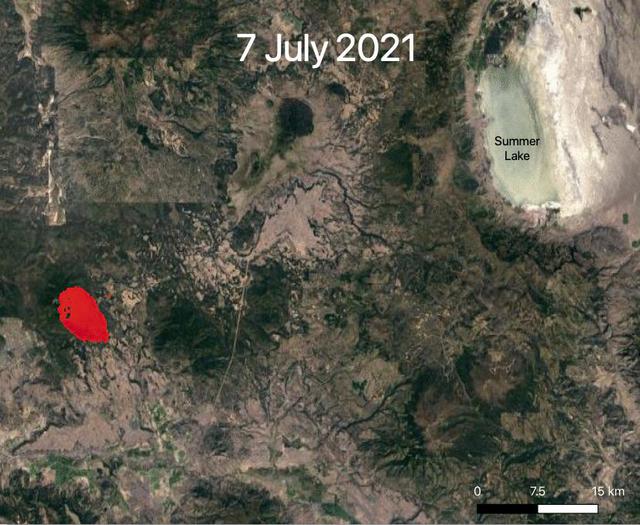
NASA's ECOsystem Spaceborne Thermal Radiometer Experiment on Space Station (ECOSTRESS) is aiding in the fight against fires in the Western U.S. As of July 27, 2021, the Bootleg Fire in southern Oregon had ballooned to more than 410,000 acres, damaging hundreds of buildings and vehicles in its path. ECOSTRESS measures surface temperature from the vantage point of the International Space Station. Researchers of the RADR-Fire team at Pacific Northwest National Laboratory have been experimenting with ECOSTRESS data as part of a new tool now being implemented for first responders like the U.S. Forest Service. In the visualization, ECOSTRESS is tracking the movement of the Bootleg Fire between July 7 and July and identifying its proximity to critical infrastructure — areas in red represent the hottest pixels ECOSTRESS detected. The extreme heat in those areas indicates the fire front, or where resources are most needed. Tasked with detecting plant water use and stress, ECOSTRESS's primary mission is to measure the temperature of plants heating up as they run out of water. But it can also measure and track heat-related phenomena like wildfires, heat waves, and volcanoes. ECOSTRESS observations have a spatial resolution of about 77 by 77 yards (70 by 70 meters), which enables researchers to study surface-temperature conditions down to the size of a football field. Due to the space station's unique orbit, the mission can acquire images of the same regions at different times of the day, as opposed to crossing over each area at the same time of day like satellites in other orbits do. This is advantageous when monitoring plant stress in the same area throughout the day, for example. Movie available at https://photojournal.jpl.nasa.gov/catalog/PIA23695
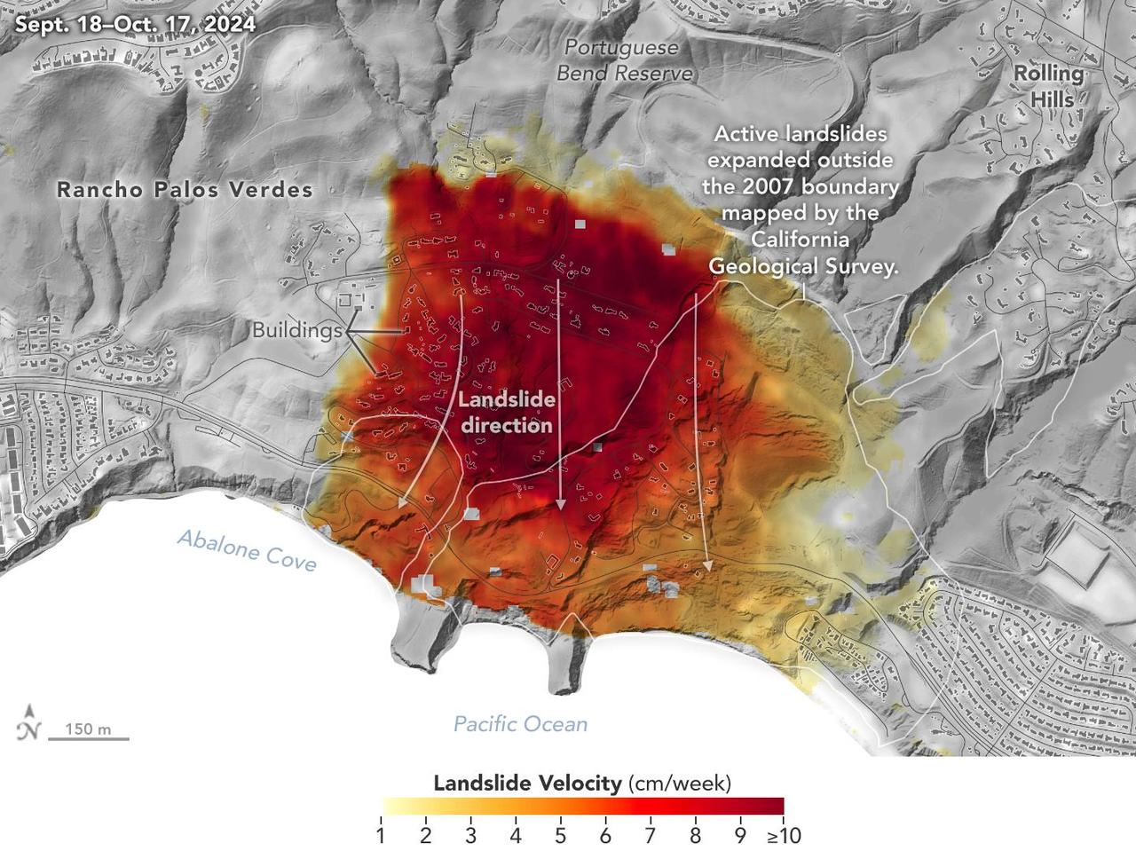
Researchers at NASA's Jet Propulsion Laboratory in Southern California used data from an airborne radar to measure the movement of the slow-moving landslides on the Palos Verdes Peninsula in Los Angeles County. The analysis determined that, during a period of four weeks in the fall of 2024, land in the residential area slid toward the ocean by as much as 4 inches (10 centimeters) per week. Portions of the peninsula, which juts into the Pacific Ocean just south of the city of Los Angeles, is part of an ancient complex of landslides and has been moving for at least the past six decades, affecting hundreds of buildings in local communities. The motion accelerated and the active area expanded following record-breaking rainfall in Southern California in 2023 and another heavy-precipitation winter in 2024. To create this visualization, the Advanced Rapid Imaging and Analysis (ARIA) team used data from four flights of NASA's Uninhabited Aerial Vehicle Synthetic Aperture Radar (UAVSAR) that took place between Sept. 18 and Oct. 17. The UAVSAR instrument was mounted to a Gulfstream III jet flown out of NASA's Armstrong Flight Research Center in Edwards, California, and the four flights were planned to estimate the speed and direction of the landslides in three dimensions. In the image, colors indicate how fast parts of the landslide complex were moving in late September and October, with the darkest reds indicating the highest speeds. The arrows represent the direction of horizontal motion. The white solid lines are the boundaries of active landslide areas as defined in 2007 by the California Geological Survey. The insights from the UAVSAR flights were part of a package of analyses by the ARIA team that also used data from ESA's (the European Space Agency's) Copernicus Sentinel-1A/B satellites. The analyses were provided to California officials to support the state's response to the landslides and made available to the public at NASA's Disaster Mapping Portal. The ARIA mission is a collaboration between JPL and Caltech, which manages JPL for NASA, to leverage radar and optical remote-sensing, GPS, and seismic observations for science as well as to aid in disaster response. The project investigates the processes and impacts of earthquakes, volcanoes, landslides, fires, subsurface fluid movement, and other natural hazards. UAVSAR has flown thousands of radar missions around the world since 2007 studying phenomena such as glaciers and ice sheets, vegetation in ecosystems, and natural hazards like earthquakes, volcanoes, and landslides. https://photojournal.jpl.nasa.gov/catalog/PIA26495