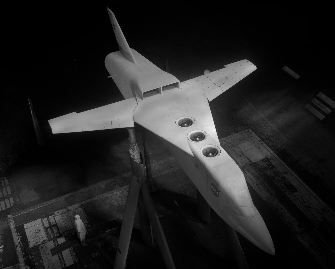
A-38524. Lift engine VSTOL fighter model, 3/4 top front view with jet engines. Edward Varerre, in picture.
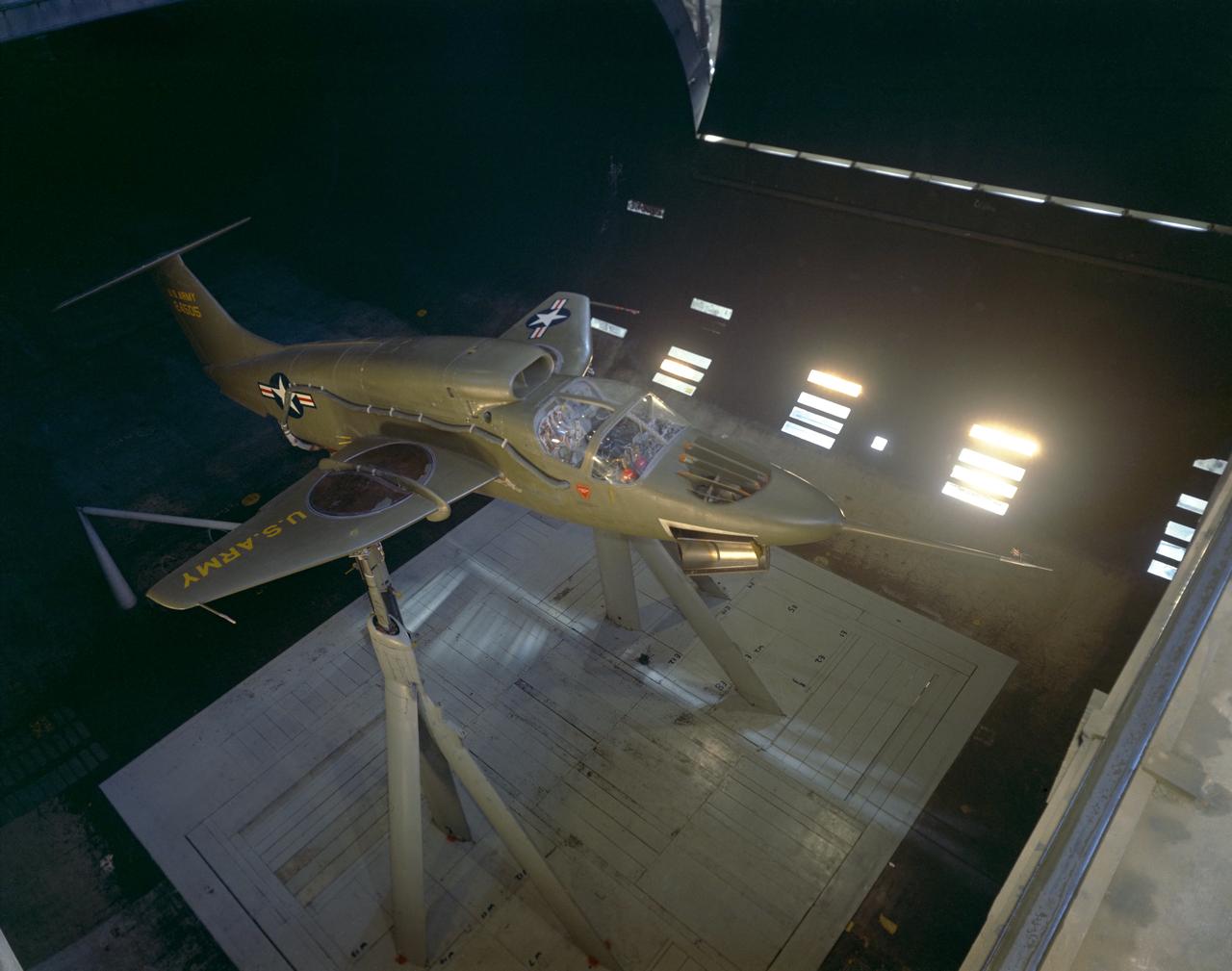
Overhead view of Ryan XV-5A lift-fan VSTOL airplane.
Lift engine VSTOL fighter model, 3/4 lower front view showing jet engines exit vanes. Yarn tufts attached to horizontal tail.

3/4 rear view Ryan XV-5A lift-fan VSTOL airplane. Pictured with Tom Wills.
3/4 front view Ryan XV-5A lift-fan VSTOL airplane. Pictured with Tom Wills.
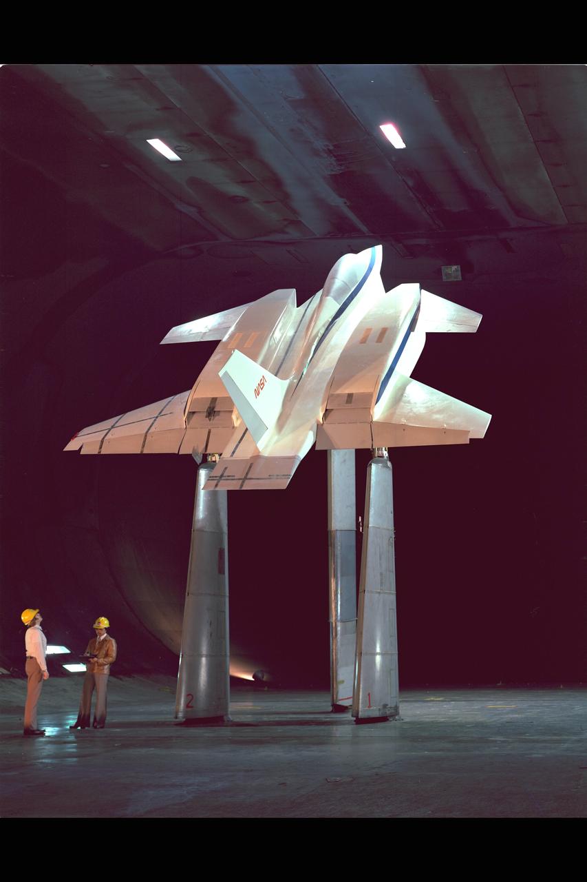
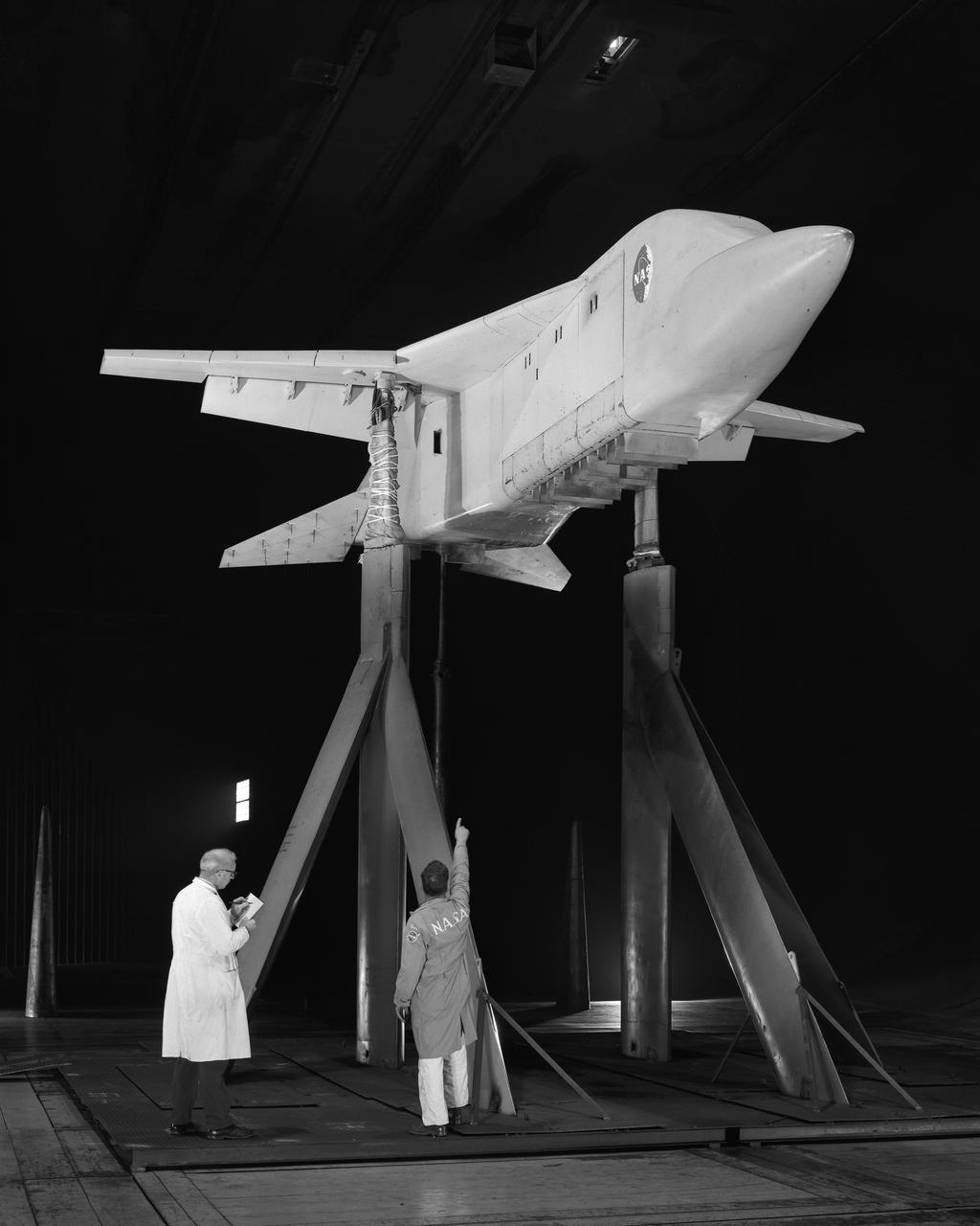
VSTOL Fighter Model in the NASA Ames 40x80ft Subsonic Wind Tunnel. Test-537 with Mike Falarski & Ray Hafalia
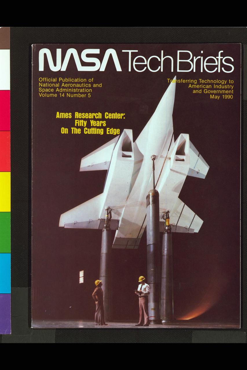
VSTOL Fighter Model in the NASA Ames 40x80ft Subsonic Wind Tunnel. Test-537 with Mike Falarski & Ray Hafalia
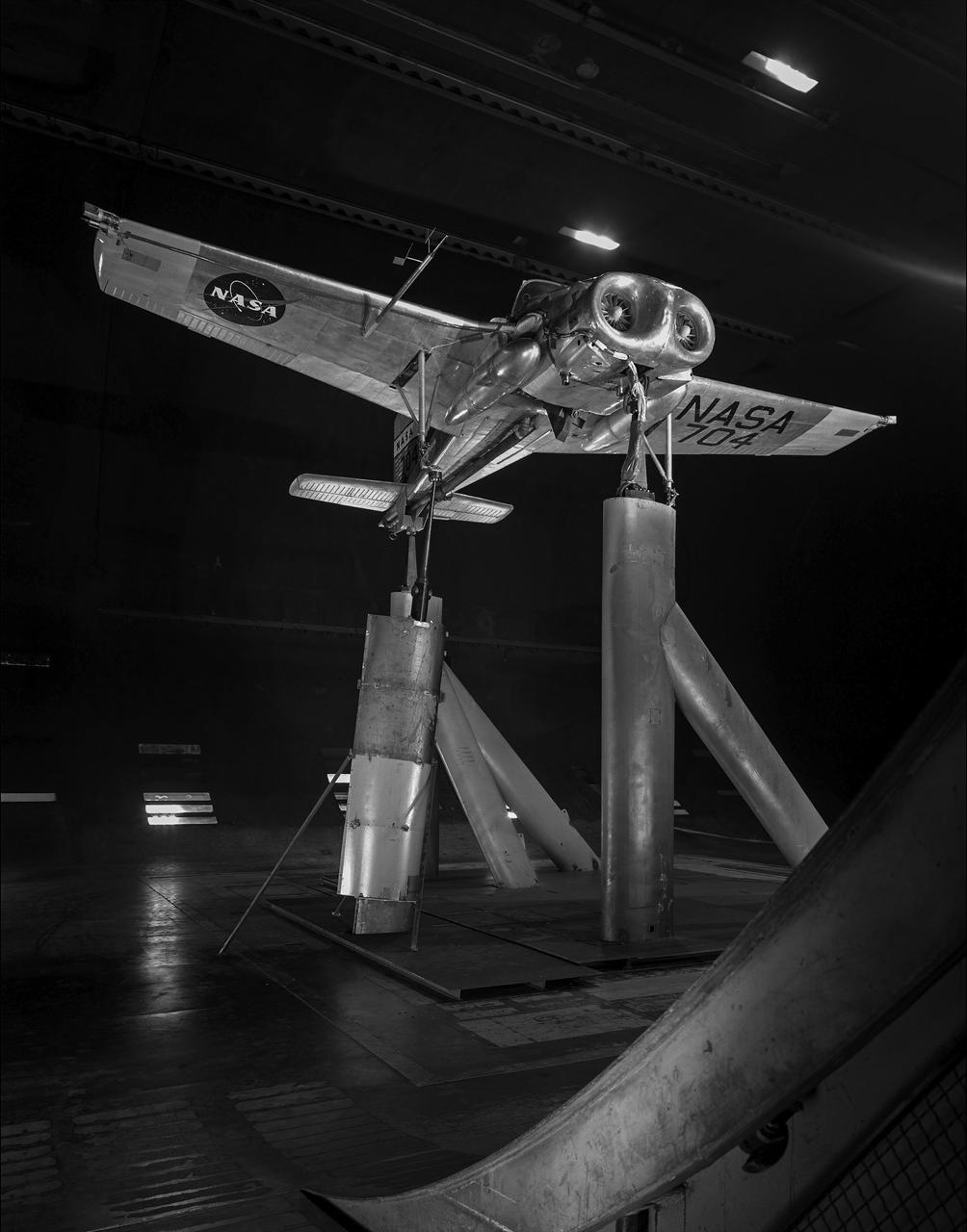
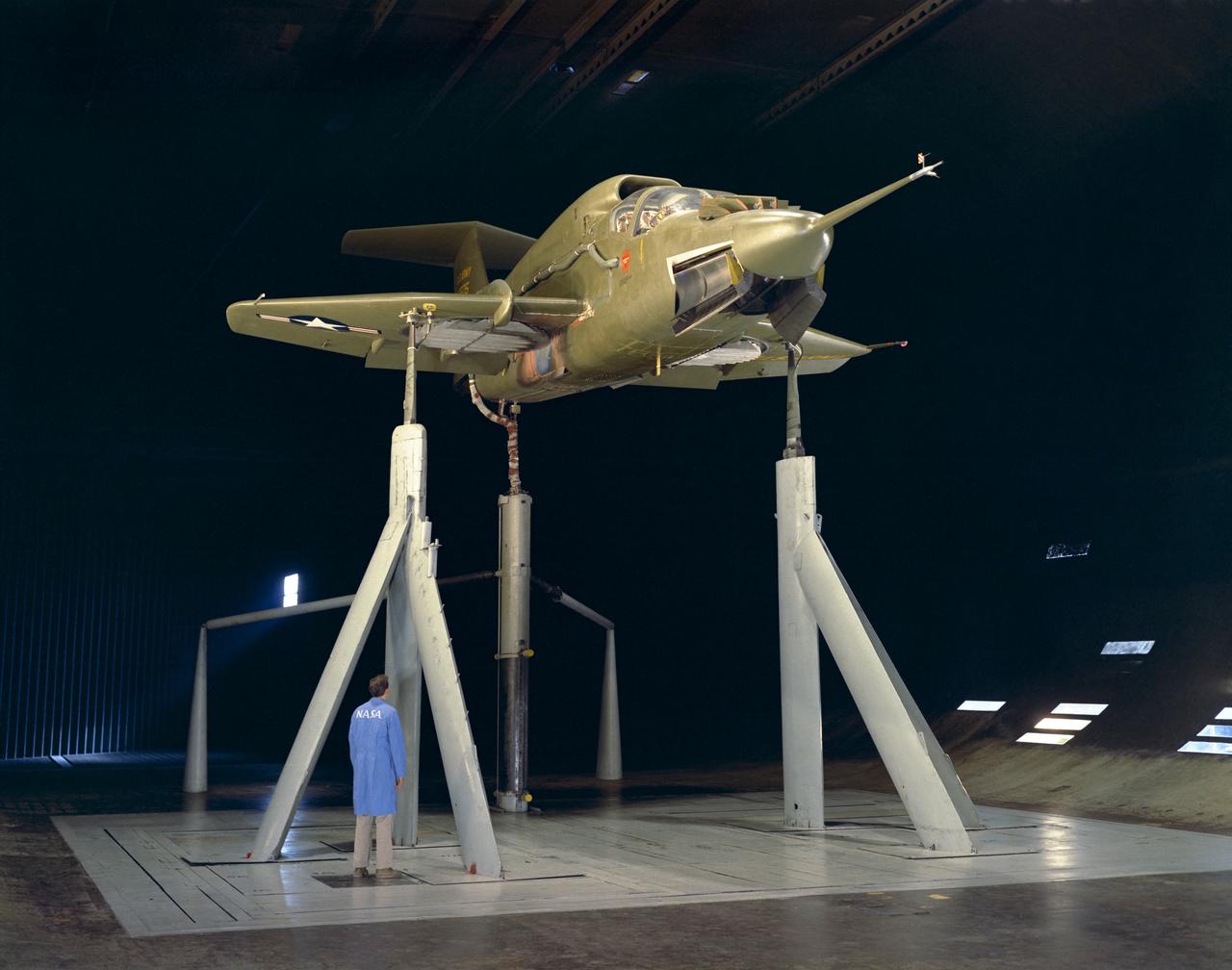
Bell V/STOL X-14 airplane mounted at 90 degrees yaw in 40x80 foot wind tunnel.
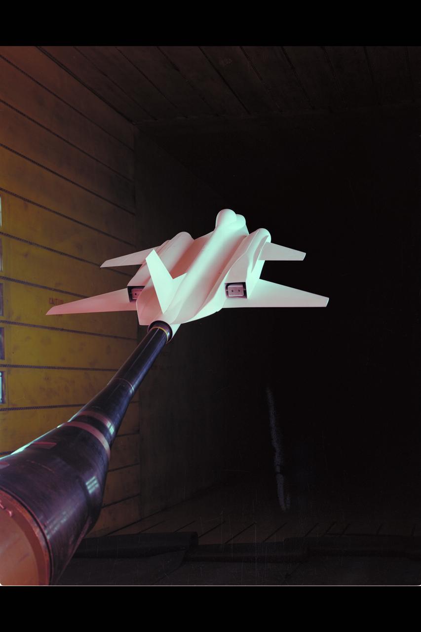
General Dynamics VSTOL Fighter model test-324 in 11x11ft w.t.
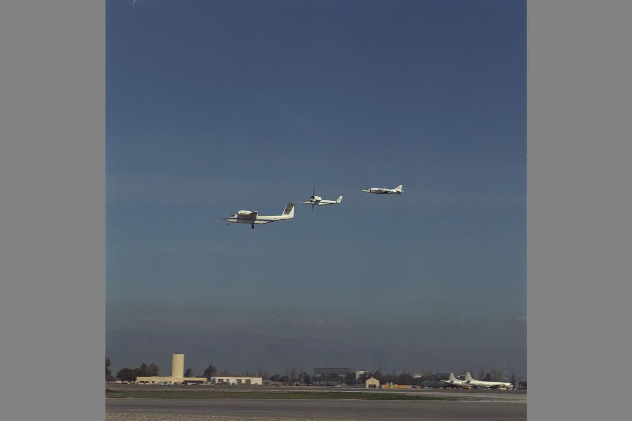
NASA AMES Photographers N-258 NAS DEDICATION CEREMONY. air show VSTOL aircraft QSRA, XV-15 Tiltrotor, AV-8B Harrier in flight formation NOTE: CROP IN ON IMAGE VERTICAL format is AC87-0180-454.1
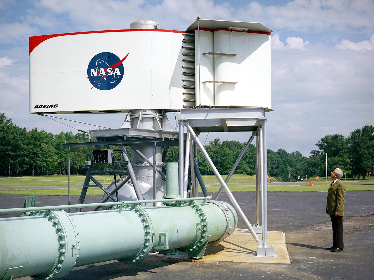
The augmentor wing concept was introduced during the early 1960s to enhance the performance of vertical and short takeoff (VSTOL) aircraft. The leading edge of the wing has full-span vertical flaps, and the trailing edge has double-slotted flaps. This provides aircraft with more control in takeoff and landing conditions. The augmentor wing also produced lower noise levels than other VSTOL designs. In the early 1970s Boeing Corporation built a Buffalo C-8A augmentor wing research aircraft for Ames Research Center. Researches at Lewis Research Center concentrated their efforts on reducing the noise levels of the wing. They initially used small-scale models to develop optimal nozzle screening methods. They then examined the nozzle designs on a large-scale model, seen here on an external test stand. This test stand included an airflow system, nozzle, the augmentor wing, and a muffler system below to reduce the atmospheric noise levels. The augmentor was lined with noise-reducing acoustic panels. The Lewis researchers were able to adjust the airflow to simulate conditions at takeoff and landing. Once the conditions were stabilized they took noise measurements from microphones placed in all directions from the wing, including an aircraft flying over. They found that the results coincided with the earlier small-scale studies for landing situations but not takeoffs. The acoustic panels were found to be successful.

National Aeronautics and Space Administration (NASA) researcher John Carpenter inspects an aircraft model with a four-fan thrust reverser which would be studied in the 9- by 15-Foot Low Speed Wind Tunnel at the Lewis Research Center. Thrust reversers were introduced in the 1950s as a means for slowing high-speed jet aircraft during landing. Engineers sought to apply the technology to Vertical and Short Takeoff and Landing (VSTOL) aircraft in the 1970s. The new designs would have to take into account shorter landing areas, noise levels, and decreased thrust levels. A balance was needed between the thrust reverser’s efficiency, its noise generation, and the engine’s power setting. This model underwent a series of four tests in the 9- by 15-foot tunnel during April and May 1974. The model, with a high-wing configuration and no tail, was equipped with four thrust-reverser engines. The investigations included static internal aerodynamic tests on a single fan/reverser, wind tunnel isolated fan/reverser thrust tests, installation effects on a four-fan airplane model in a wind tunnel, and single reverser acoustic tests. The 9-by 15 was built inside the return leg of the 8- by 6-Foot Supersonic Wind Tunnel in 1968. The facility generates airspeeds from 0 to 175 miles per hour to evaluate the aerodynamic performance and acoustic characteristics of nozzles, inlets, and propellers, and investigate hot gas re-ingestion of advanced VSTOL concepts. John Carpenter was a technician in the Wind Tunnels Service Section of the Test Installations Division.
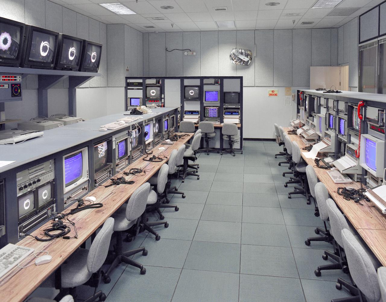
Mission control Blue Room, seen here, in building 4800 at NASA's Dryden Flight Research Center, is part of the Western Aeronautical Test Range (WATR). All aspects of a research mission are monitored from one of two of these control rooms at Dryden. The WATR consists of a highly automated complex of computer controlled tracking, telemetry, and communications systems and control room complexes that are capable of supporting any type of mission ranging from system and component testing, to sub-scale and full-scale flight tests of new aircraft and reentry systems. Designated areas are assigned for spin/dive tests, corridors are provided for low, medium, and high-altitude supersonic flight, and special STOL/VSTOL facilities are available at Ames Moffett and Crows Landing. Special use airspace, available at Edwards, covers approximately twelve thousand square miles of mostly desert area. The southern boundary lies to the south of Rogers Dry Lake, the western boundary lies midway between Mojave and Bakersfield, the northern boundary passes just south of Bishop, and the eastern boundary follows about 25 miles west of the Nevada border except in the northern areas where it crosses into Nevada.