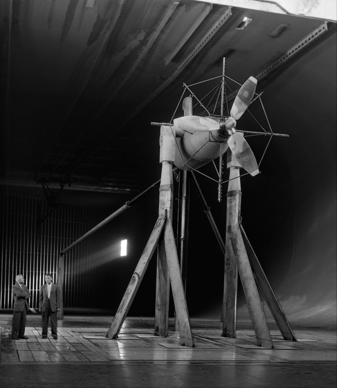
Investigation of cambered propeller design for VTOL/STOL airplane. 3/4 front view of Curtis VTOL propeller.
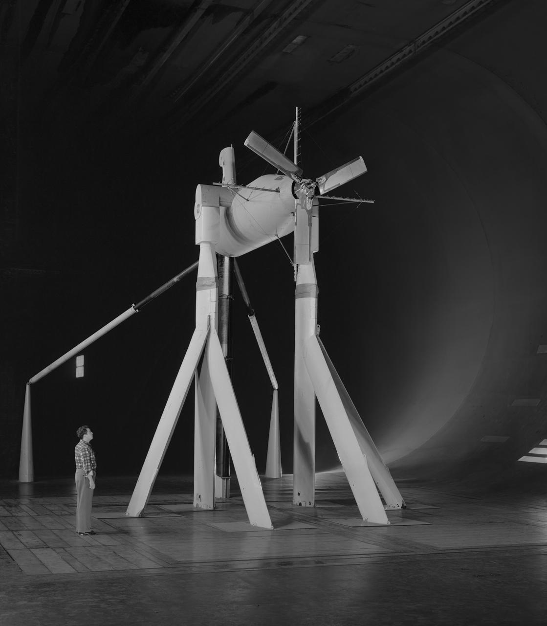
Collins Aerodyne VTOL Vertical take off and landing model in the 40x80 foot wind tunnel at NASA's Ames Research Center. Designed by Alexander Lippisch.
Investigation of cambered propeller design for VTOL/STOL airplane. 3/4 front view of complete configuration, 0 deg.
Collins Aerodyne vertical take-off and landing (VTOL) aircraft investigations. Ground plane support system. 3/4 front view. Dave Koening (from Collins Aerodyne) in photo. Mounted on variable height struts, ground board system, zero degree angle of attack. 01/11/1960
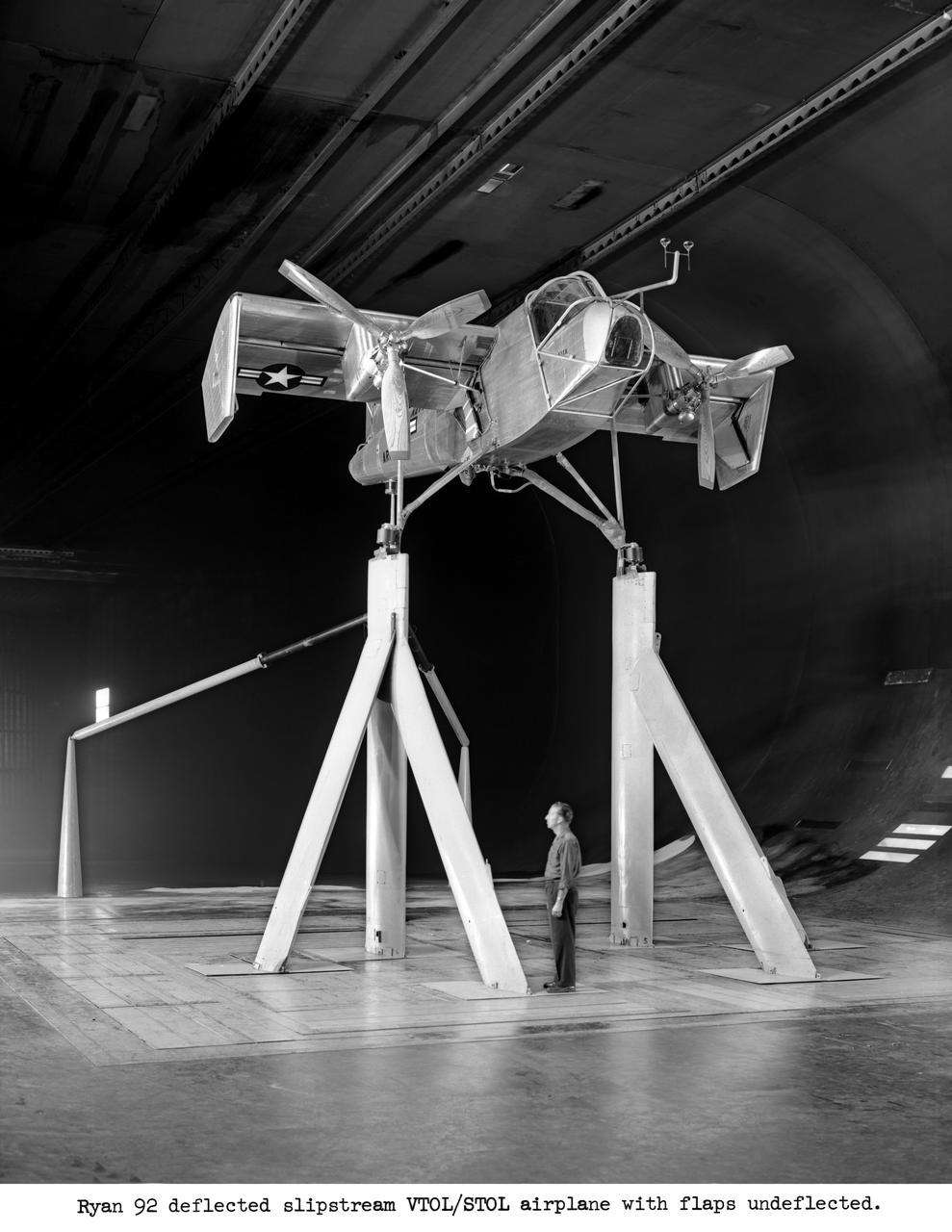
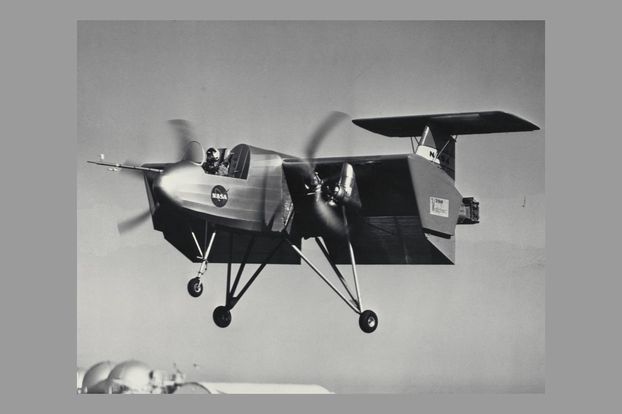
Ryan #92 deflected slipstream VTOL/STOL airplane with flaps undeflected.

Doak VTOL Aircraft
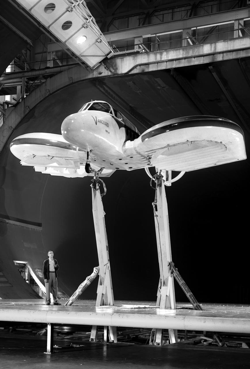
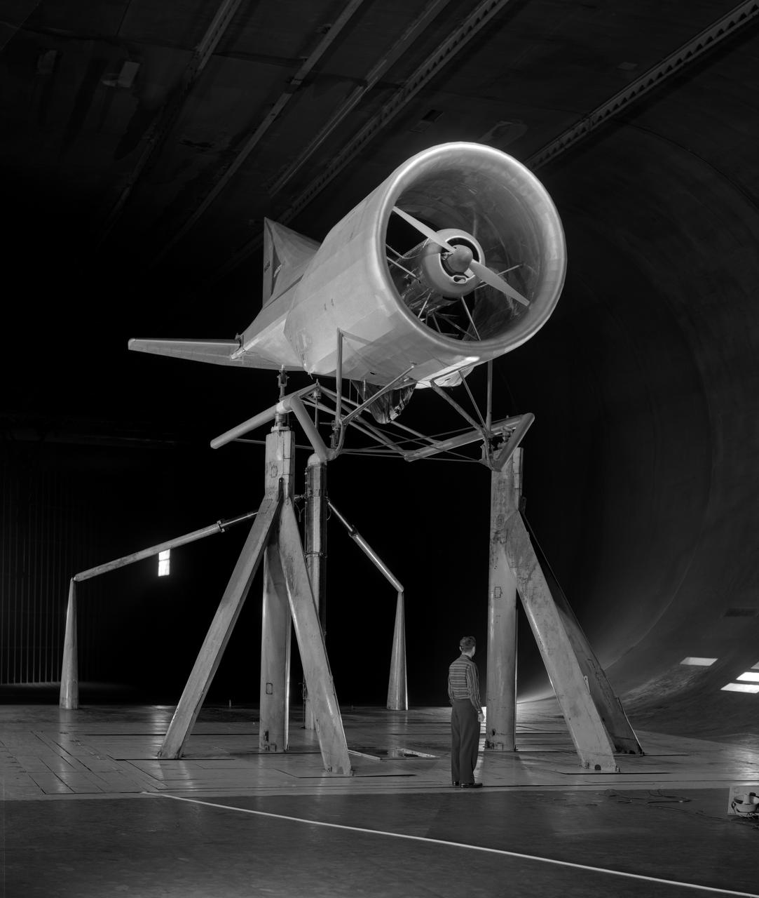
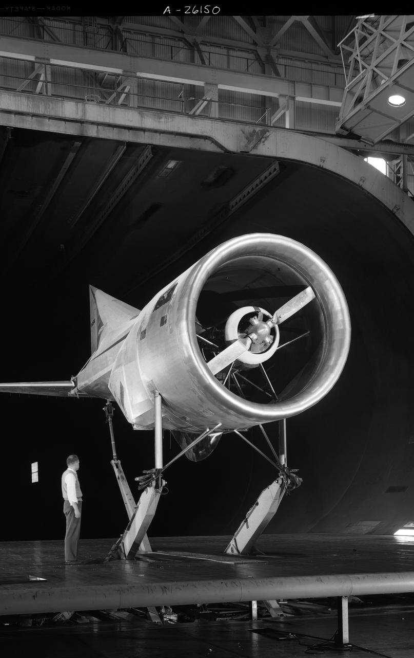
Vanguard 2C vertical take-off and landing (VTOL) airplane, wind tunnel test. Front view from below, model 14 1/2 feet high disk off. Nasa Ames engineer Ralph Maki in photo. Variable height struts and ground plane, low pressure ratio, fan in wing. 02/01/1960.
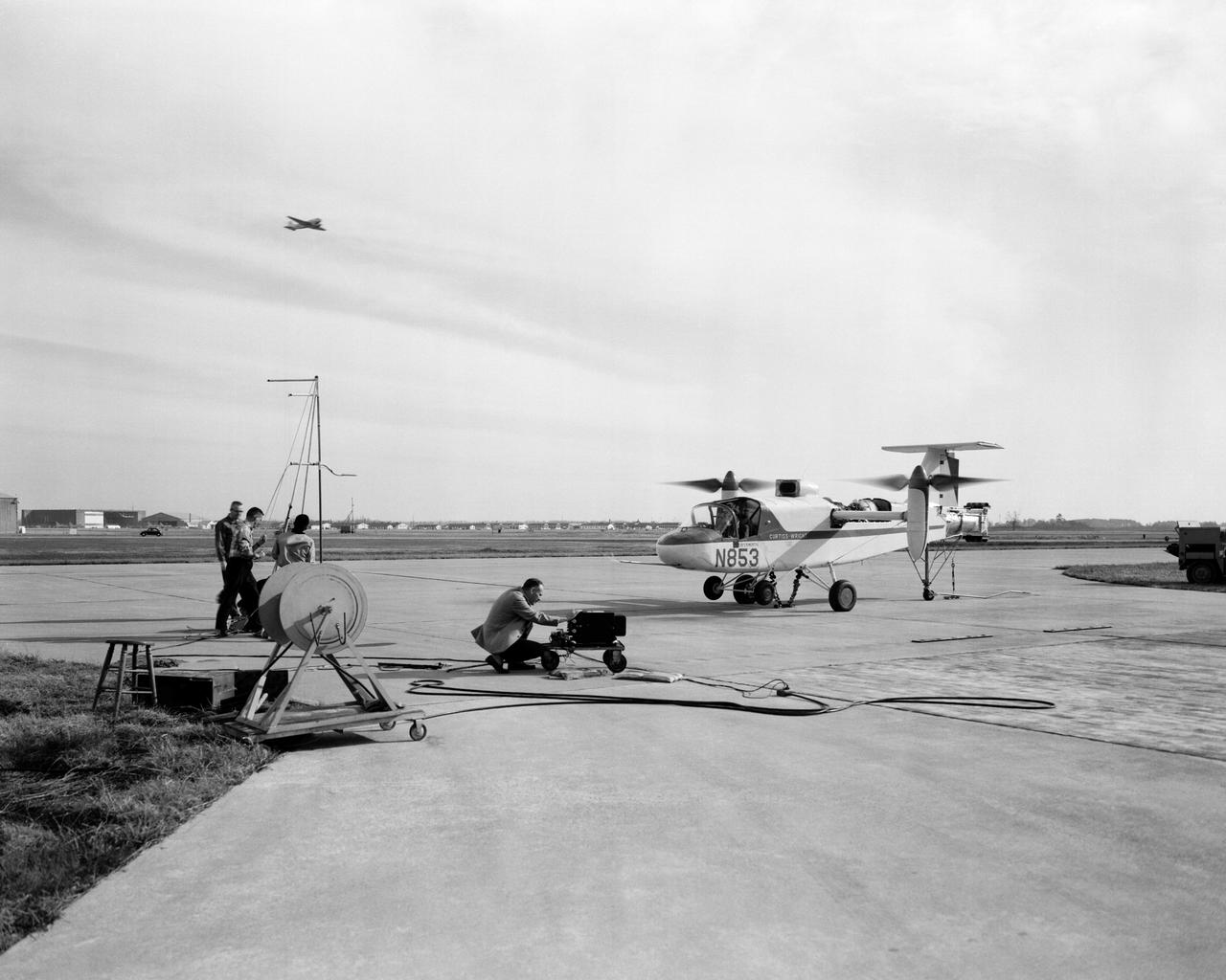
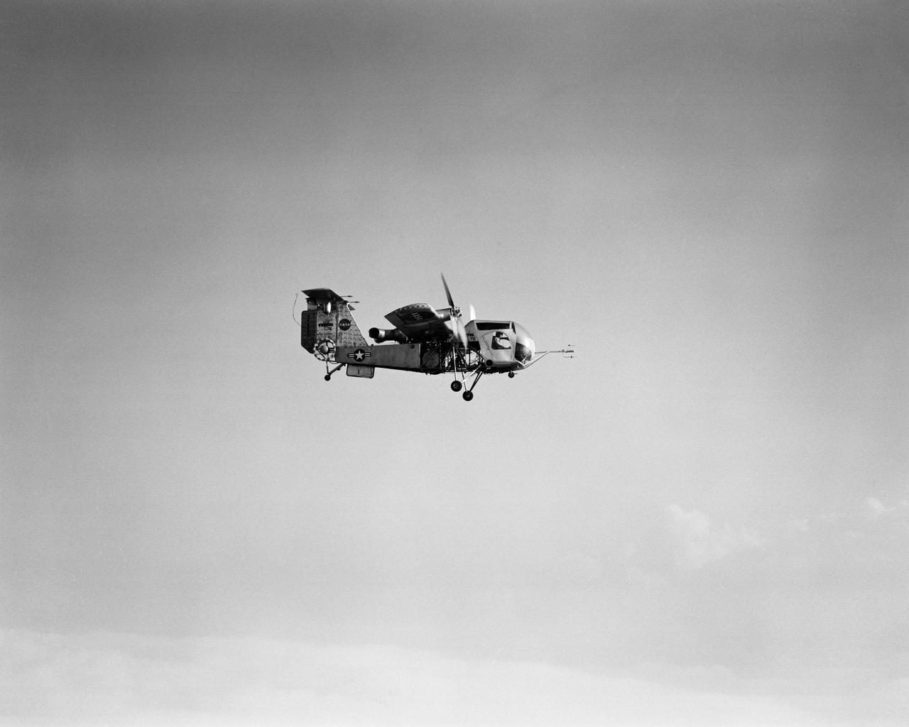
Curtiss-Wright X-100 (VTOL) Vertical Take-Off Transport.
Vertol 76 Tilt Wing VTOL. Photographed 9/13/1960. Photograph published in Sixty Years of Aeronautical Research 1917-1977 By David A. Anderton, A NASA publication, Page 62.
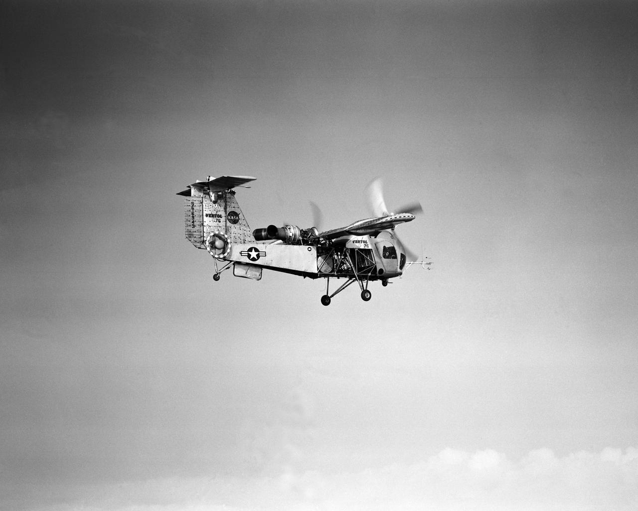
Vertol 76 Tilt Wing VTOL. Photographed 9/13/1960. Photograph published in Sixty Years of Aeronautical Research 1917-1977 By David A. Anderton, A NASA publication, Page 62.
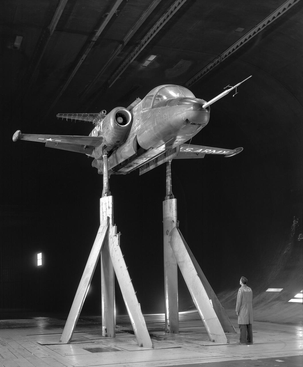
3/4 front view of XV-4A Hummingbird VTOL Research Vehicle in Ames 40x80 wind tunnel with Tom Wills in Photo.
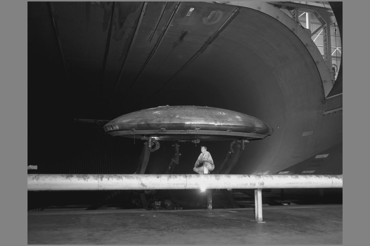
Avrocar Annular Jet VTOL Airplane in Ames 40x80 foot Wind Tunnel.
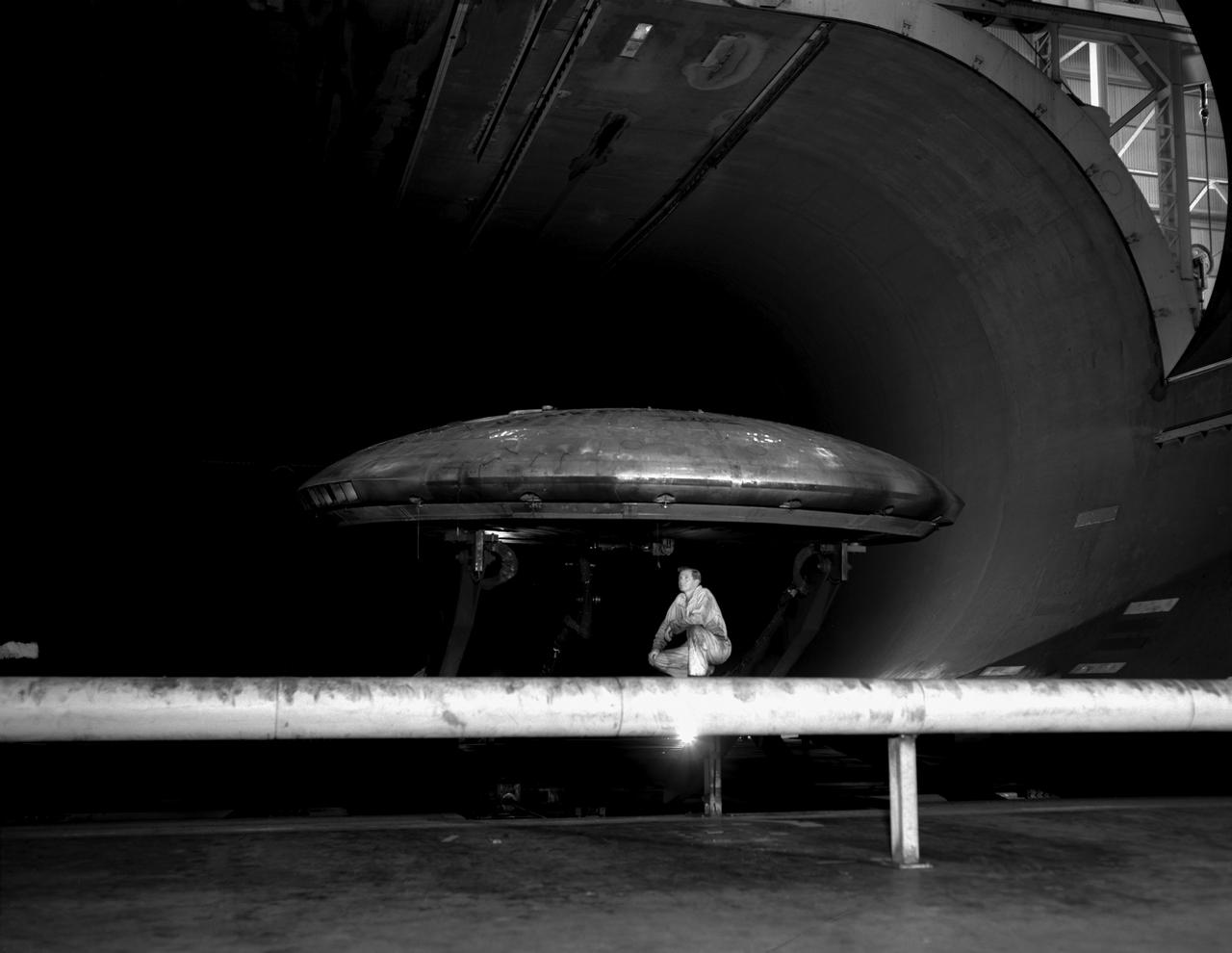
3/4 front view of Avrocar without tail, showing ground board and variable height struts. The ground board minimizes the boundary layer on the floor under the model. black and white negative: KODAK T-MAX 100 Professional. SBA settings neutral SBA on, color SBA on

Vertol VZ-2 (Model 76): Arriving at Langley from Edwards Air Force Base, California, this Vertol VZ-2 underwent almost a year and a half of flight research before going back to the manufacturer for rework. The VZ-2 was used to investigate Vertical Take-Off and Landing (VTOL).
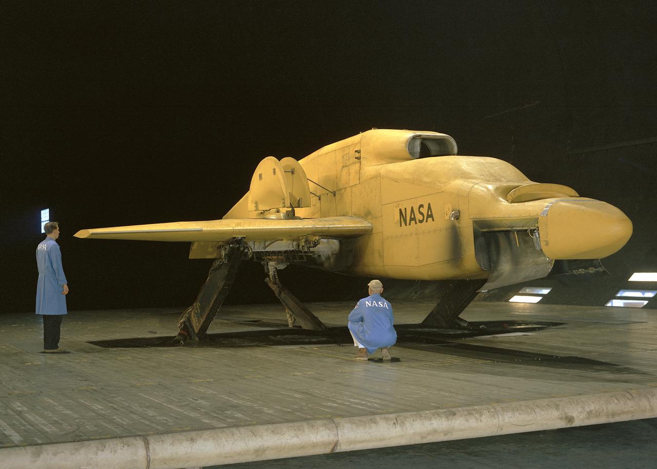
3/4 front view VZ-11 ground test - variable height struts. Engines of the VZ-11 are a pair of General Electric J85-5 turbojets, mounted in high in the centre fuselage, well away from fan disturbance. Designed in the Ames 40x80 foot wind tunnel.
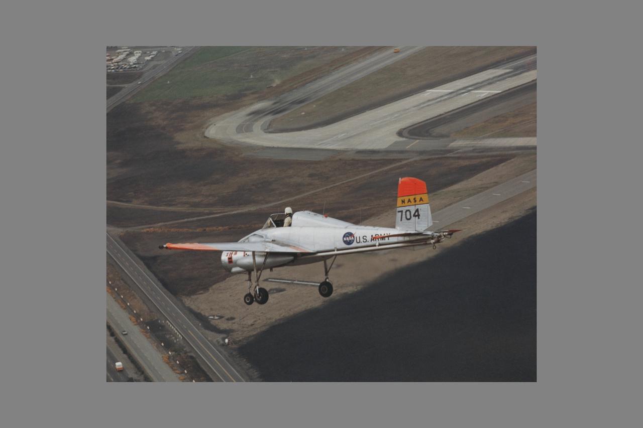
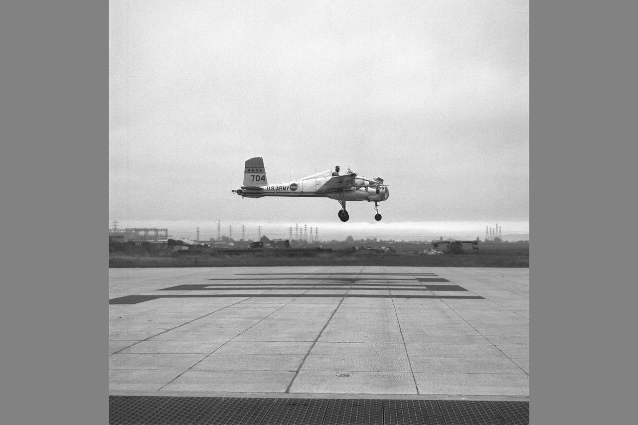
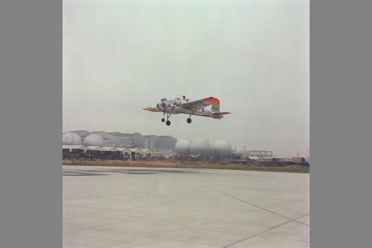
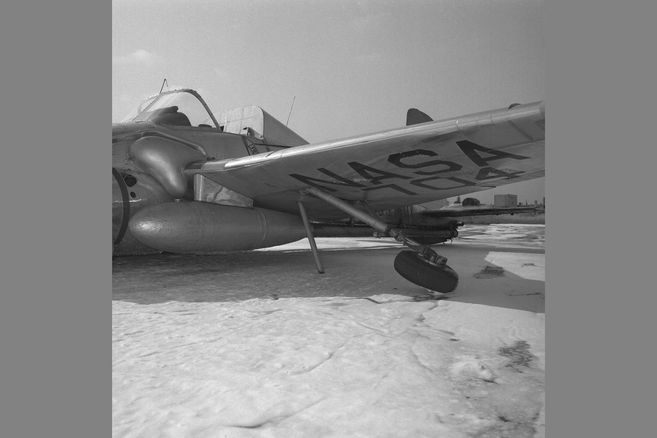
X-14B NASA-704: A Bell single-place, open cockpit, twin-engine, jet-lift VTOL aircraft over Highway 101 in approach to Moffett Field, California. The X-14 was used by NASA Ames Research Center to advance state-of-the-art jet-powered VTOL aircraft.
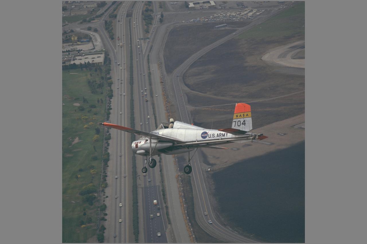
X-14B NASA-704: A Bell single-place, open cockpit, twin-engine, jet-lift VTOL aircraft over Highway 101 in approach to Moffett Field, California. The X-14 was used by NASA Ames Research Center to advance state-of-the-art jet-powered VTOL aircraft.
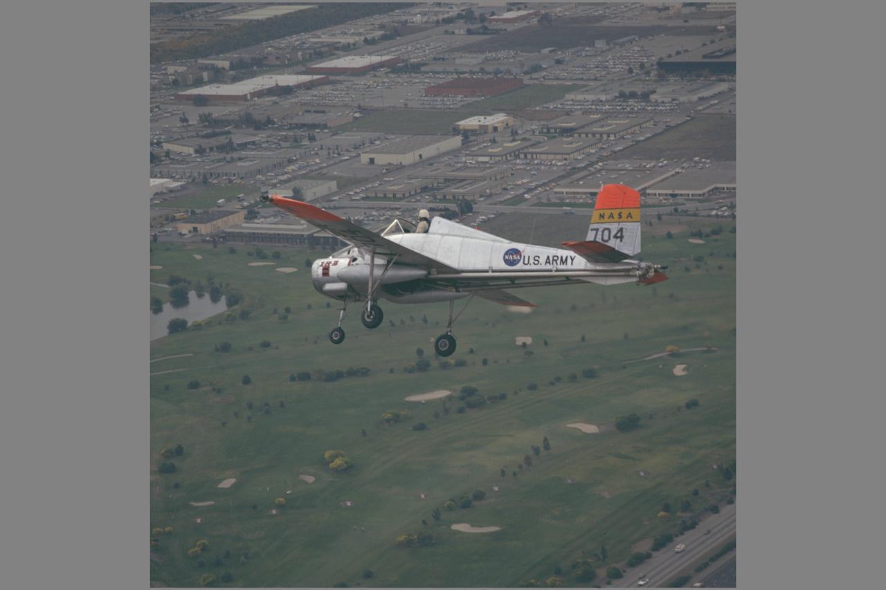
X-14B NASA-704: A Bell single-place, open cockpit, twin-engine, jet-lift VTOL aircraft in flight over Sunnyvale golf course. The X-14 was used by NASA Ames Research Center to advance state-of-the-art jet-powered VTOL aircraft.
X-14 Aircraft during hover flight tests at VTOL test pad
X-14 Aircraft during hover flight tests at VTOL test pad
AVROCAR Annular Jet VTOL Airplane; 40x80ft w.t. tests
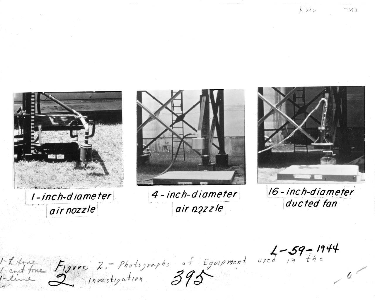
Image for NASA Document NASA-TN-D-56. Equipment Used In Investigation. Document Title: An investigation to determine conditions under which downwash from VTOL aircraft will start surface erosion from various types of terrain Figure 2. Equipment Used In Investigation
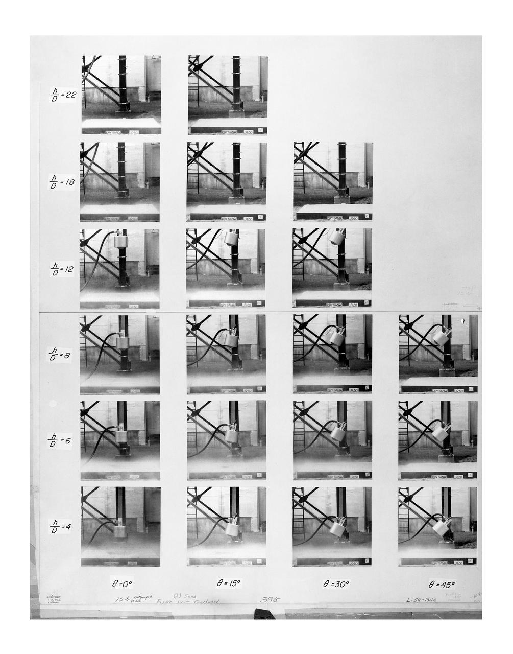
Figure 12(a) Effects of Inclining Water. Figure 12(b) Sand. NASA-TN-D-56 An investigation to determine conditions under which downwash from VTOL aircraft will start surface erosion from various types of terrain.
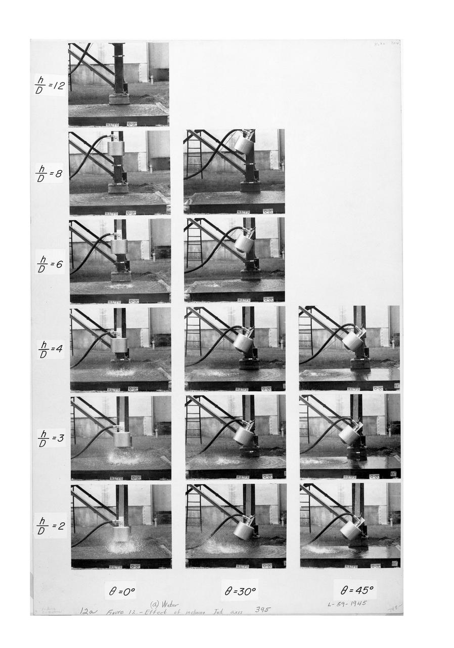
Figure 12(a) Effects of Inclining Water. Figure 12(b) Sand. NASA-TN-D-56 An investigation to determine conditions under which downwash from VTOL aircraft will start surface erosion from various types of terrain.
Accident: X-14B crash on VTOL Pad Ames Research Center, Moffett Field, CA Photo Credit: NASA Ames student photographer Jim Huss
Accident: X-14B crash on VTOL Pad Ames Research Center, Moffett Field, CA Photo Credit: NASA Ames student photographer Jim Huss
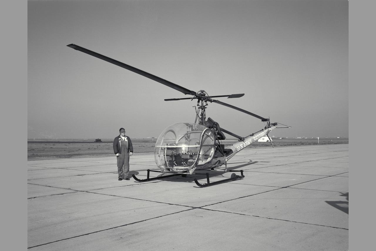
3/4 FRONT VIEW OF HILLER H-23C (USA 56-2288). USE OF THE HILLER H-23 HELICOPTER AS AN AID IN ESTABLISHING SATISFACTORY FLYING QUALITIES & REQUIREMENTS FOR VTOL AIRCRAFT. Rotocraft Research. NASA SP Flight Research at Ames: 57 Years of Development and Validation of Aeronautical Technology
VZ-3RY (AF 56-6941, NASA 235, NASA 705) Vertiplane - Level flight 25 knots, flaps deflection 60 degrees. Flight investigation o f the flying qualities of a deflected slipstream VTOL aircraft. Note: Used in publication in Flight Research at Ames; 57 Years of Development and Validation of Aeronautical Technology NASA SP-1998-3300 fig. 115
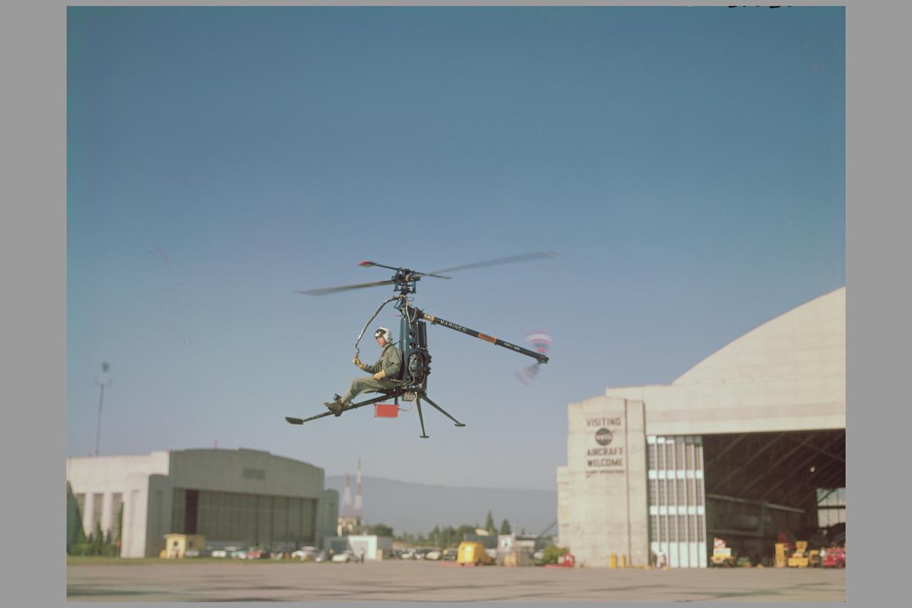
Ames aerodynamicists tested a wide variety of VTOL aircraft and helicopters during the 1960's. Here the Hiller rotorcycle YROE-1, made by Hiller Helicopter in nearby PaloAlto, California, hovers in front of the Ames Hangar. (4020, 4021, 4024) Published in NASA SP Flight Research at Ames: 57 Years of Development and Validation of Aeronautical Technology and Ames 60yr History Atmosphere of Freedom.
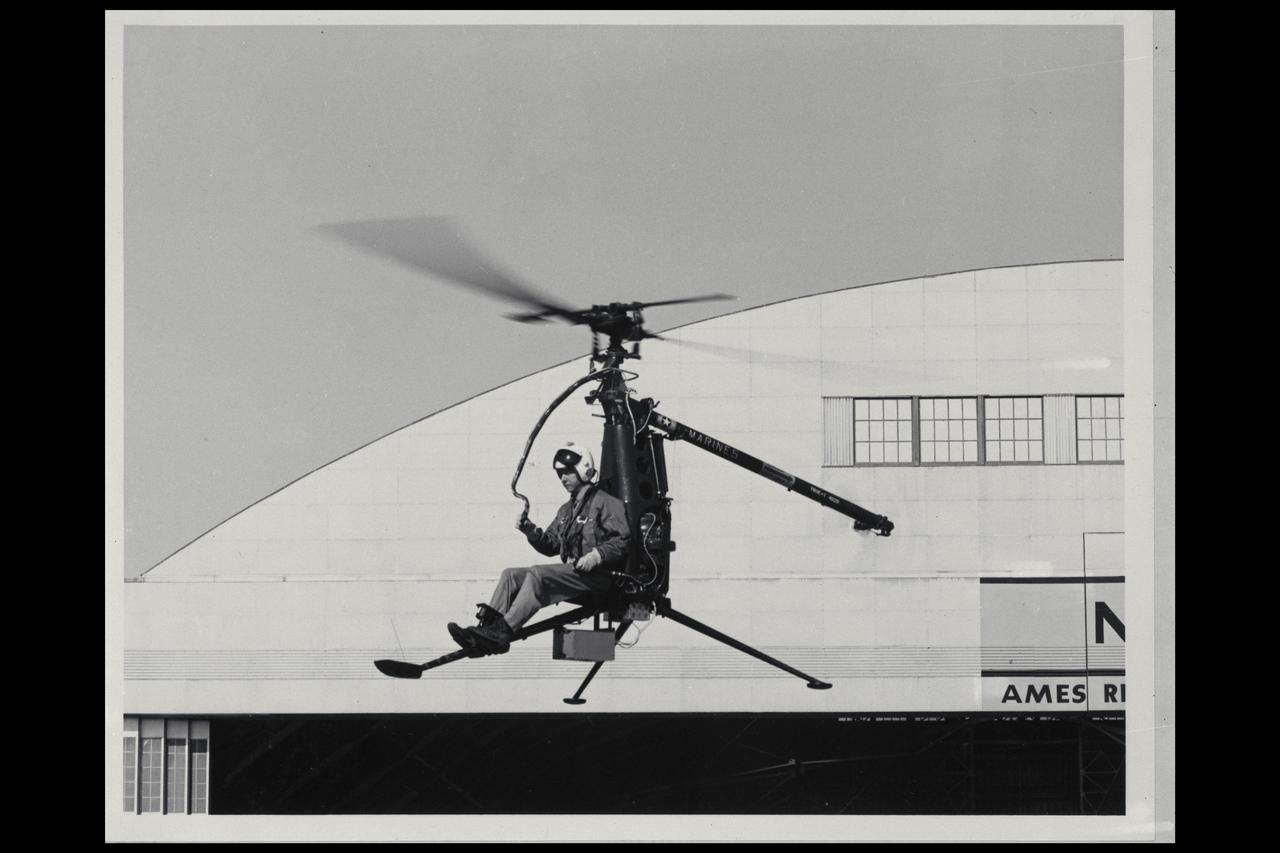
Ames aerodynamicists tested a wide variety of VTOL aircraft and helicopters during the 1960's Here the Hiller rotorcycle YROE-1, made by Hiller Helicopter in nearby Palo Alto, California, hovers in front of the Ames Hangar. The Rotorcycle was a small, 500pound, single-place helicopter. Tests indicated that the vehicle was unsafe because of low yaw-control capability to the right; the design also had oor crashworthiness.
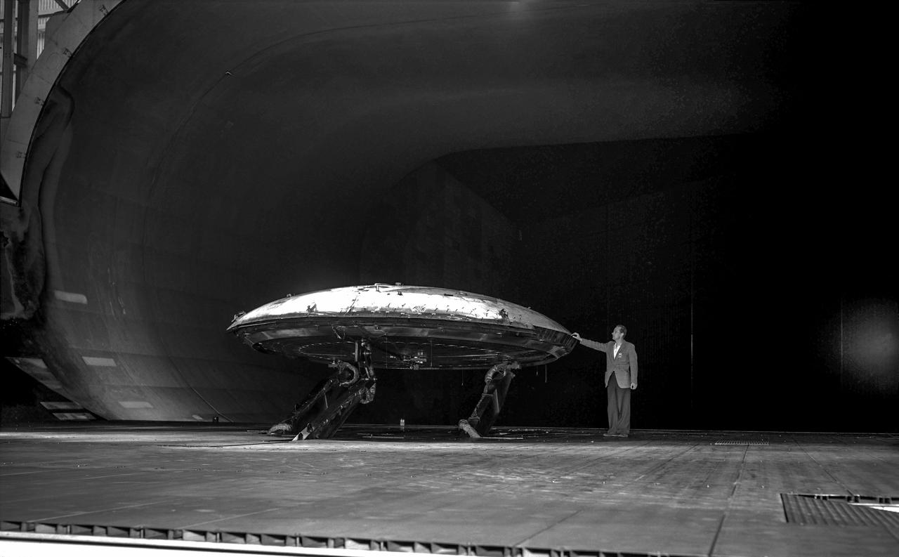
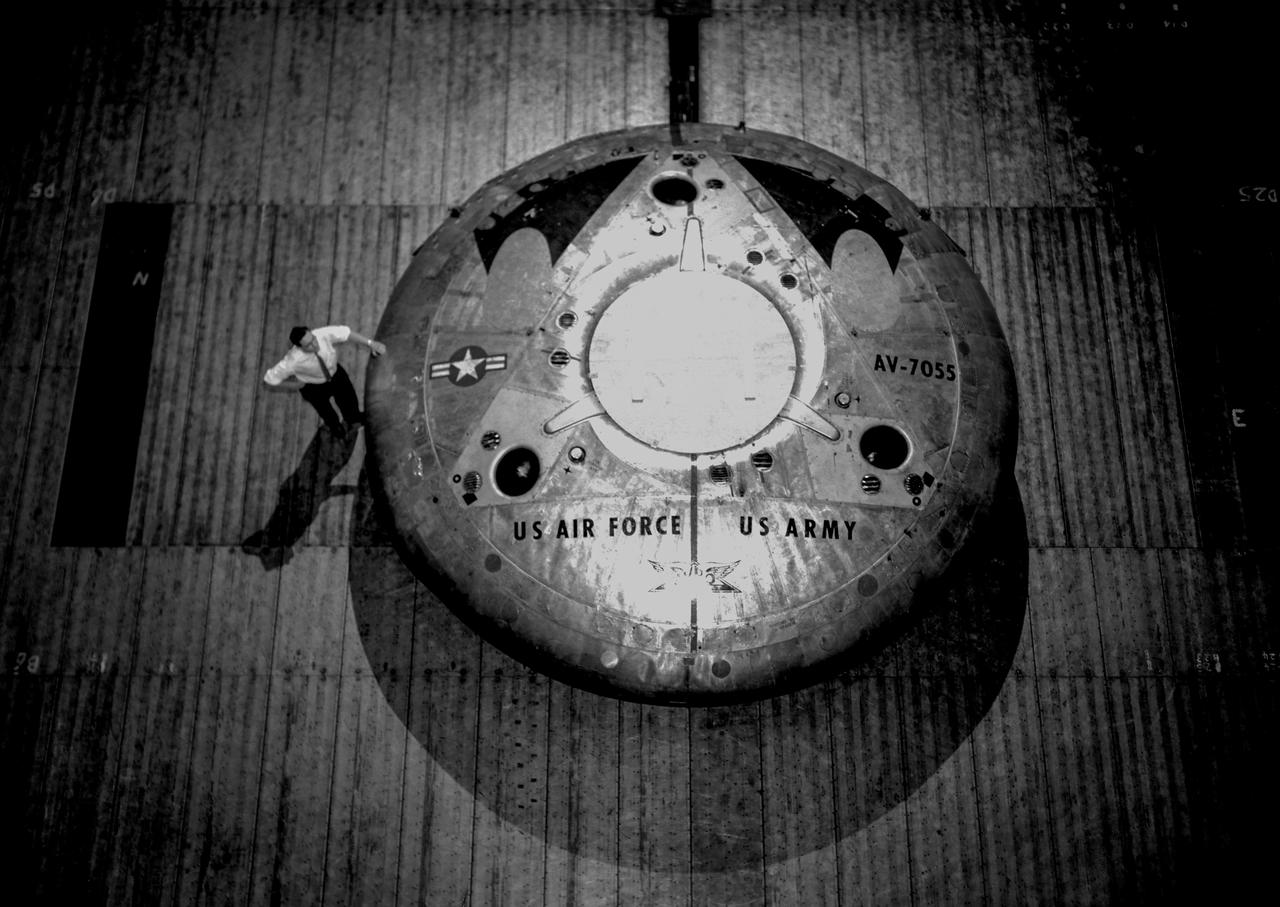
Rear view of the Avrocar without the tail, with ground board and variable height struts. The air force wanted to test the design of a flying saucer with vertical takeoff and landing capability. The design proved unstable without the tail.
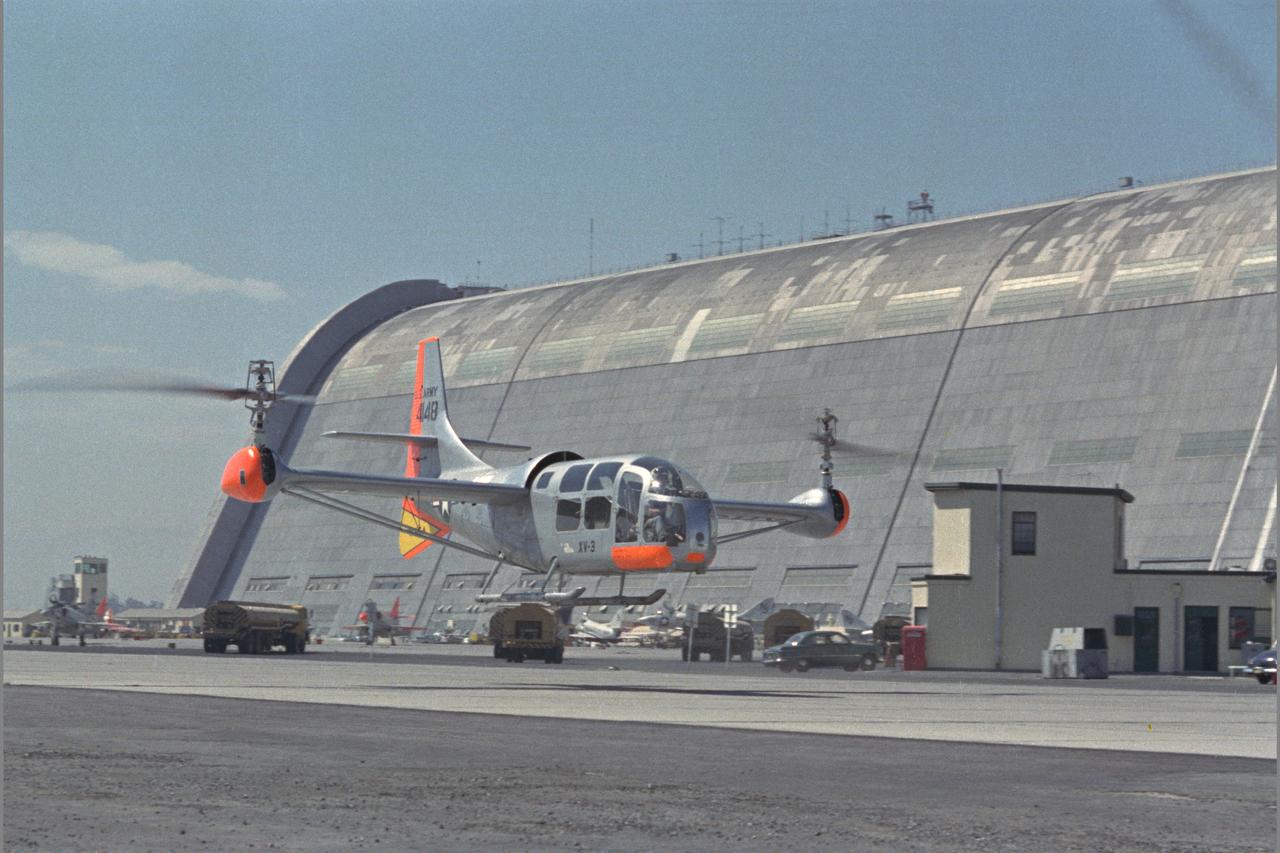
XV-3 HOVERING ON RAMP. Flight Test of Bell XV-3 Convertiplane. Bell VTOL tilt-rotor aircraft hovering along side Hangar One at Moffett Field. The XV-3 design combined a helicopter rotor and a wing. A 450 horsepower Pratt & Whitney piston engine drove the two rotors. The XV-3, first flown in 1955 , was the first tilt-rotor to achieve 100% tilting of rotors. The vehicle was underpowered, however, and could not hover out of ground effect. Note the large ventral fin, which was added to imrpove directional stability in cruse (Oct 1962)
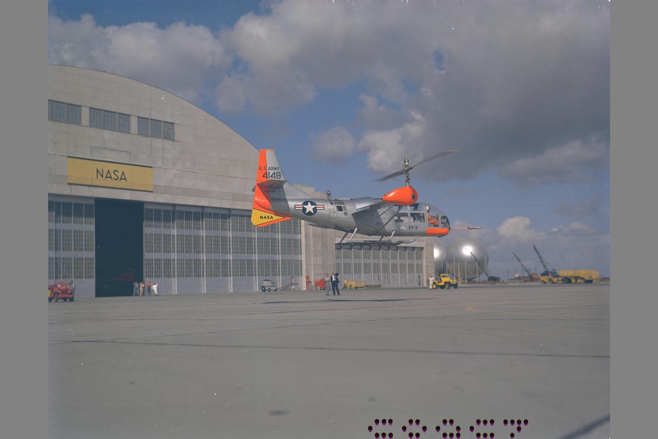
XV-3 HOVERING ON RAMP. Flight Test of Bell XV-3 Convertiplane. Bell VTOL tilt-rotor aircraft hovering in front of building N-211 at Moffett Field. The XV-3 design combined a helicopter rotor and a wing. A 450 horsepower Pratt & Whitney piston engine drove the two rotors. The XV-3, first flown in 1955 , was the first tilt-rotor to achieve 100% tilting of rotors. The vehicle was underpowered, however, and could not hover out of ground effect. Note the large ventral fin, which was added to imrpove directional stability in cruse (Oct 1962)
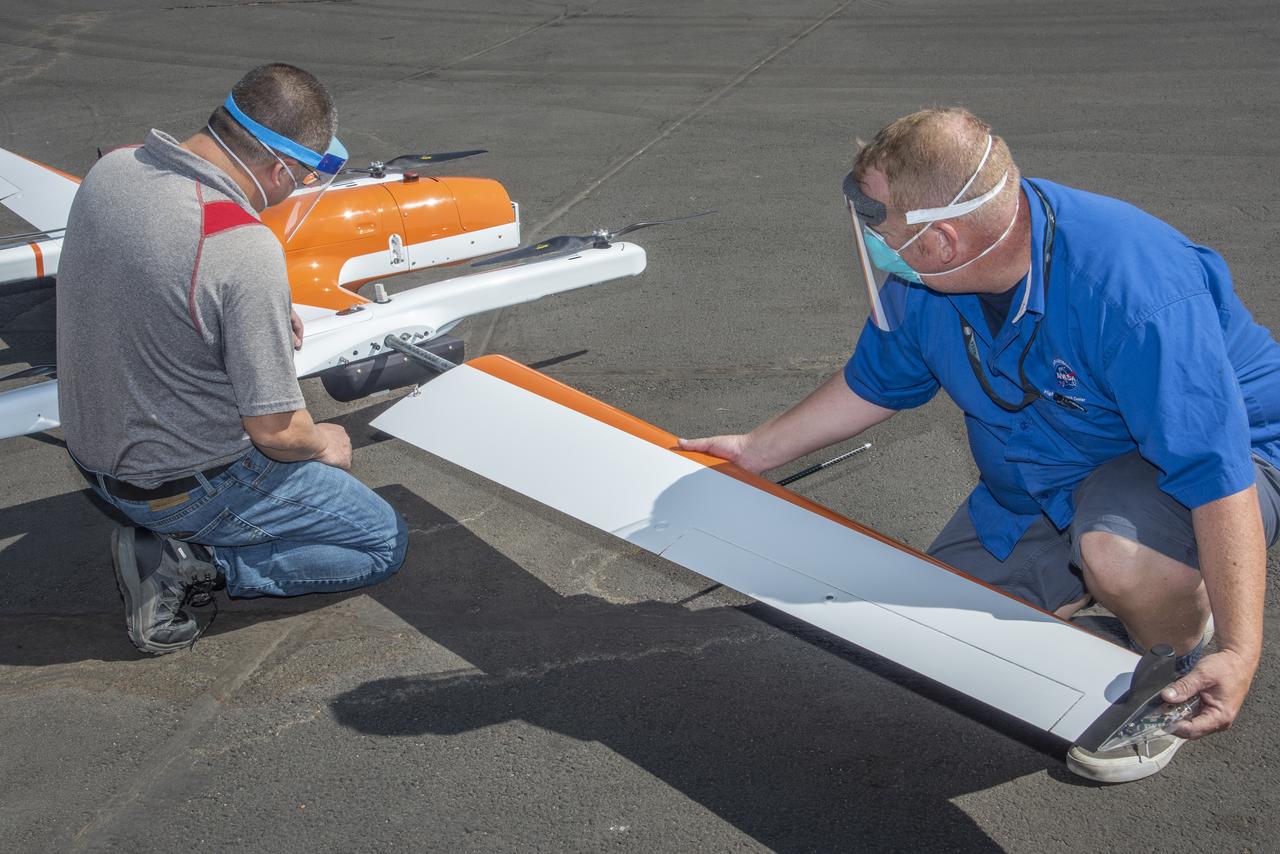
Derek Abramson and Robert Jensen install a wing on the Hybrid Quadrotor 90C (HQ-90) at NASA Armstrong Flight Research Center's Dale Reed Subscale Flight Research Lab in California on Oct. 1, 2020. This vertical lift and transition remotely piloted aircraft arrived in pieces packed in crates for the Resilient Autonomy project to test software in flight.
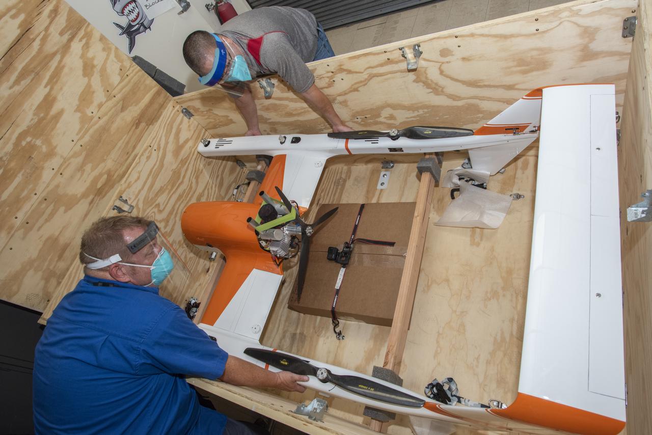
Derek Abramson and Robert Jensen unload the Hybrid Quadrotor 90C (HQ-90) at NASA Armstrong Flight Research Center’s Dale Reed Subscale Flight Research Lab in California on Oct. 1, 2020. The Resilient Autonomy project will use the vertical lift and transition remotely piloted aircraft for software testing at NASA Armstrong.
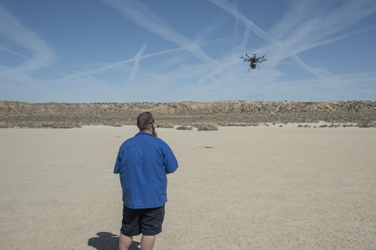
Justin Hall flies the Alta 8 remotely piloted aircraft in March 2021 at Rosamond North Lakebed at NASA’s Armstrong Flight Research Center in Edwards, California. The Resilient Autonomy project used these flights to collect data with the Nav Module hardware and software developed by NASA’s Jet Propulsion Laboratory in Pasadena, California.
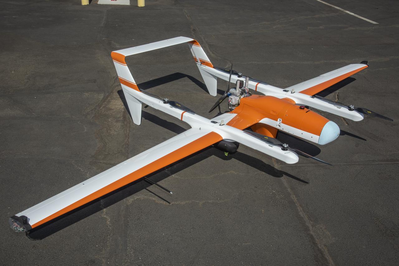
The Hybrid Quadrotor 90C (HQ-90) is displayed outside the NASA Armstrong Flight Research Center’s Dale Reed Subscale Flight Research Lab in California on Oct. 1, 2020. The Resilient Autonomy project will use this vertical lift and transition remotely piloted aircraft for software testing.
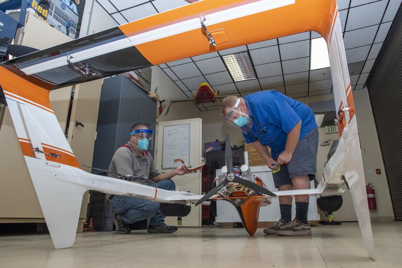
Derek Abramson and Robert Jensen assemble pieces of the Hybrid Quadrotor 90C (HQ-90) at NASA Armstrong Flight Research Center’s Dale Reed Subscale Flight Research Lab in California on Oct. 1, 2020. This vertical lift and transition remotely piloted aircraft arrived in pieces packed in crates. It was reassembled for the Resilient Autonomy project to test software in flight.
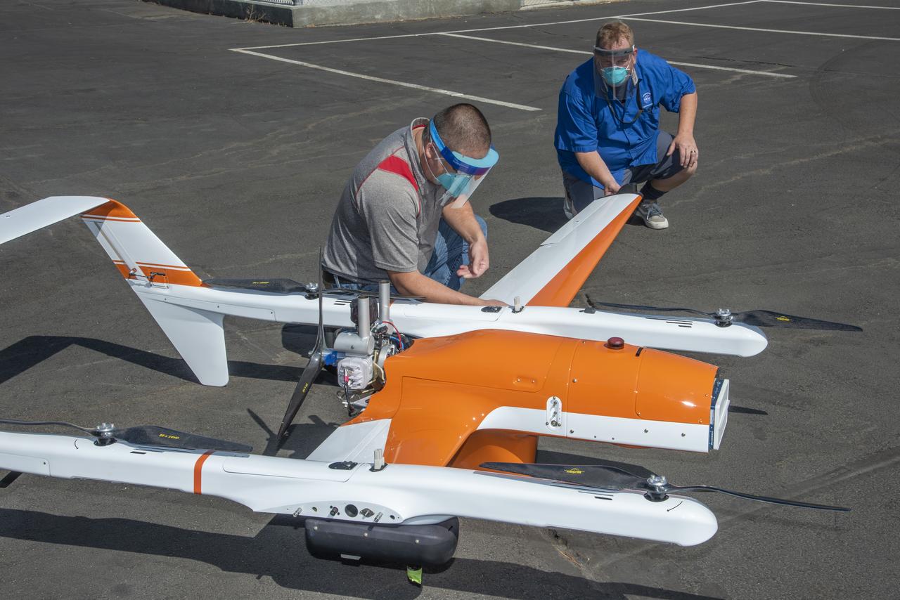
Derek Abramson and Robert Jensen install one of two wings on the Hybrid Quadrotor 90C (HQ-90) at NASA Armstrong Flight Research Center's Dale Reed Subscale Flight Research Lab in California on Oct. 1, 2020. This vertical lift and transition remotely piloted aircraft arrived in pieces packed in crates for the Resilient Autonomy project to test software in flight.
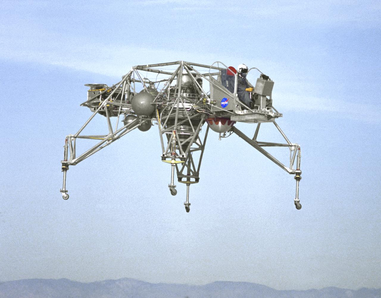
In this NASA Flight Reserch Center photograph the Lunar Landing Research Vehicle (LLRV) number 1 is shown in flight. When Apollo planning was underway in 1960, NASA was looking for a simulator to profile the descent to the Moon's surface. Three concepts surfaced: an electronic simulator, a tethered device, and the ambitious Dryden contribution, a free-flying vehicle. All three became serious projects, but eventually the NASA Flight Research Center's (FRC) Landing Research Vehicle (LLRV) became the most significant one. Hubert M. Drake is credited with originating the idea, while Donald Bellman and Gene Matranga were senior engineers on the project, with Bellman, the project manager. Simultaneously, and independently, Bell Aerosystems Company, Buffalo, N.Y., a company with experience in vertical takeoff and landing (VTOL) aircraft, had conceived a similar free-flying simulator and proposed their concept to NASA headquarters. NASA Headquarters put FRC and Bell together to collaborate. The challenge was; to allow a pilot to make a vertical landing on Earth in a simulated Moon environment, one sixth of the Earth's gravity and with totally transparent aerodynamic forces in a "free flight" vehicle with no tether forces acting on it. Built of tubular aluminum like a giant four-legged bedstead, the vehicle was to simulate a lunar landing profile from around 1500 feet to the Moon's surface. To do this, the LLRV had a General Electric CF-700-2V turbofan engine mounted vertically in gimbals, with 4200 pounds of thrust. The engine, using JP-4 fuel, got the vehicle up to the test altitude and was then throttled back to support five-sixths of the vehicle's weight, simulating the reduced gravity of the Moon. Two hydrogen-peroxide lift rockets with thrust that could be varied from 100 to 500 pounds handled the LLRV's rate of descent and horizontal translations. Sixteen smaller hydrogen-peroxide rockets, mounted in pairs, gave the pilot control in pitch, yaw, and roll. On the LLRV,
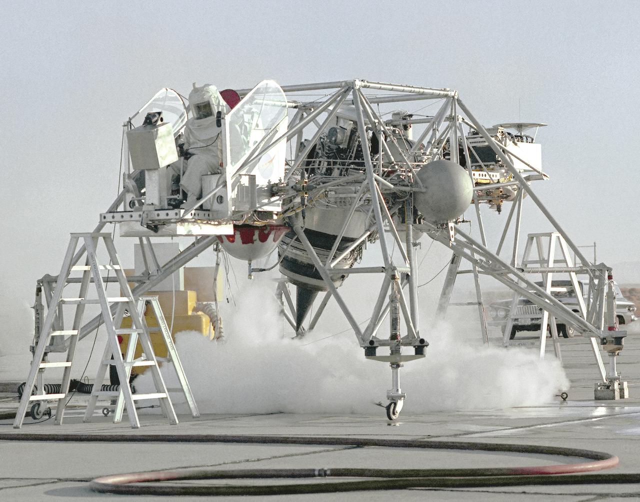
This 1964 NASA Flight Reserch Center photograph shows a ground engine test underway on the Lunar Landing Research Vehicle (LLRV) number 1. When Apollo planning was underway in 1960, NASA was looking for a simulator to profile the descent to the Moon's surface. Three concepts surfaced: an electronic simulator, a tethered device, and the ambitious Dryden contribution, a free-flying vehicle. All three became serious projects, but eventually the NASA Flight Research Center's (FRC) Landing Research Vehicle (LLRV) became the most significant one. Hubert M. Drake is credited with originating the idea, while Donald Bellman and Gene Matranga were senior engineers on the project, with Bellman, the project manager. Simultaneously, and independently, Bell Aerosystems Company, Buffalo, N.Y., a company with experience in vertical takeoff and landing (VTOL) aircraft, had conceived a similar free-flying simulator and proposed their concept to NASA headquarters. NASA Headquarters put FRC and Bell together to collaborate. The challenge was; to allow a pilot to make a vertical landing on Earth in a simulated Moon environment, one sixth of the Earth's gravity and with totally transparent aerodynamic forces in a "free flight" vehicle with no tether forces acting on it. Built of tubular aluminum like a giant four-legged bedstead, the vehicle was to simulate a lunar landing profile from around 1500 feet to the Moon's surface. To do this, the LLRV had a General Electric CF-700-2V turbofan engine mounted vertically in gimbals, with 4200 pounds of thrust. The engine, using JP-4 fuel, got the vehicle up to the test altitude and was then throttled back to support five-sixths of the vehicle's weight, simulating the reduced gravity of the Moon. Two hydrogen-peroxide lift rockets with thrust that could be varied from 100 to 500 pounds handled the LLRV's rate of descent and horizontal translations. Sixteen smaller hydrogen-peroxide rockets, mounted in pairs, gave the pilot control in pitch, yaw,
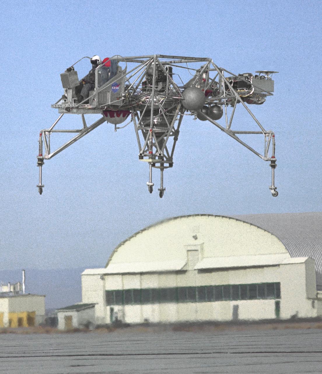
An inflight view from the left side of the Lunar Landing Research Vehicle, is shown in this 1964 NASA Flight Research Center photograph. The photograph was taken in front of the old NACA hangar located at the South Base, Edwards Air Force Base. When Apollo planning was underway in 1960, NASA was looking for a simulator to profile the descent to the Moon's surface. Three concepts surfaced: an electronic simulator, a tethered device, and the ambitious Dryden contribution, a free-flying vehicle. All three became serious projects, but eventually the NASA Flight Research Center's (FRC) Landing Research Vehicle (LLRV) became the most significant one. Hubert M. Drake is credited with originating the idea, while Donald Bellman and Gene Matranga were senior engineers on the project, with Bellman, the project manager. Simultaneously, and independently, Bell Aerosystems Company, Buffalo, N.Y., a company with experience in vertical takeoff and landing (VTOL) aircraft, had conceived a similar free-flying simulator and proposed their concept to NASA headquarters. NASA Headquarters put FRC and Bell together to collaborate. The challenge was; to allow a pilot to make a vertical landing on earth in a simulated Moon environment, one sixth of the earth's gravity and with totally transparent aerodynamic forces in a "free flight" vehicle with no tether forces acting on it. Built of tubular aluminum like a giant four-legged bedstead, the vehicle was to simulate a lunar landing profile from around 1500 feet to the Moon's surface. To do this, the LLRV had a General Electric CF-700-2V turbofan engine mounted vertically in gimbals, with 4200 pounds of thrust. The engine, using JP-4 fuel, got the vehicle up to the test altitude and was then throttled back to support five-sixths of the vehicle's weight, simulating the reduced gravity of the Moon. Two hydrogen-peroxide lift rockets with thrust that could be varied from 100 to 500 pounds handled the LLRV's rate of descent and horizontal transla
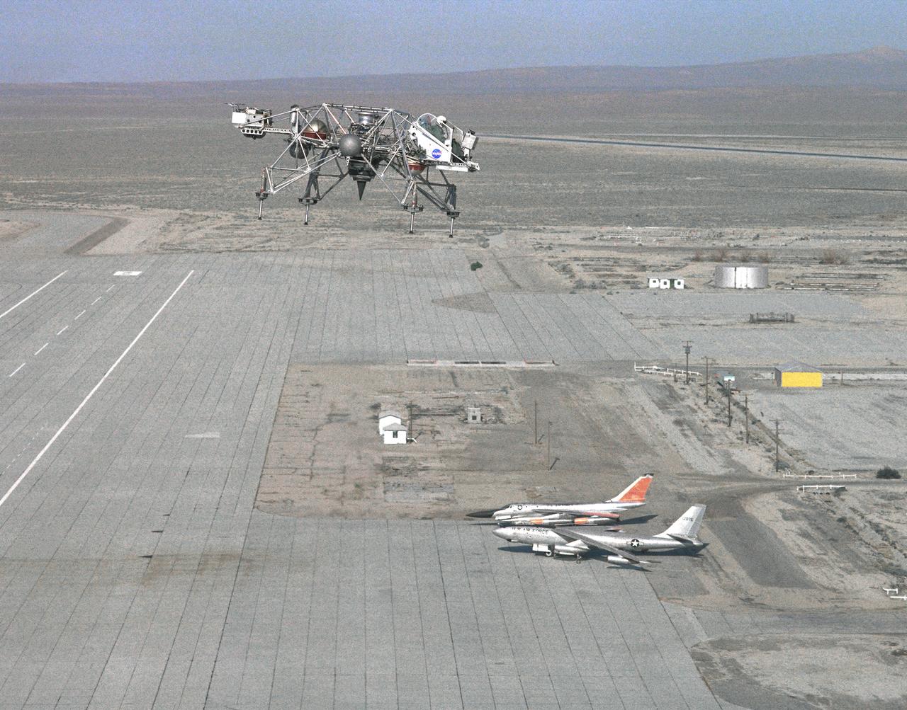
In this 1965 NASA Flight Reserch Center photograph the Lunar Landing Research Vehicle (LLRV) is shown at near maximum altitude over the south base at Edwards Air Force Base. When Apollo planning was underway in 1960, NASA was looking for a simulator to profile the descent to the moon's surface. Three concepts surfaced: an electronic simulator, a tethered device, and the ambitious Dryden contribution, a free-flying vehicle. All three became serious projects, but eventually the NASA Flight Research Center's (FRC) Landing Research Vehicle (LLRV) became the most significant one. Hubert M. Drake is credited with originating the idea, while Donald Bellman and Gene Matranga were senior engineers on the project, with Bellman, the project manager. Simultaneously, and independently, Bell Aerosystems Company, Buffalo, N.Y., a company with experience in vertical takeoff and landing (VTOL) aircraft, had conceived a similar free-flying simulator and proposed their concept to NASA headquarters. NASA Headquarters put FRC and Bell together to collaborate. The challenge was; to allow a pilot to make a vertical landing on Earth in a simulated moon environment, one sixth of the Earth's gravity and with totally transparent aerodynamic forces in a "free flight" vehicle with no tether forces acting on it. Built of tubular aluminum like a giant four-legged bedstead, the vehicle was to simulate a lunar landing profile from around 1500 feet to the moon's surface. To do this, the LLRV had a General Electric CF-700-2V turbofan engine mounted vertically in gimbals, with 4200 pounds of thrust. The engine, using JP-4 fuel, got the vehicle up to the test altitude and was then throttled back to support five-sixths of the vehicle's weight, simulating the reduced gravity of the moon. Two hydrogen-peroxide lift rockets with thrust that could be varied from 100 to 500 pounds handled the LLRV's rate of descent and horizontal translations. Sixteen smaller hydrogen-peroxide rockets, mounted in pairs, gav

The XV-15 tilt rotor ships #1 and #2 parked on the NASA Dryden Flight Research Center ramp. The XV-15s, manufactured by Bell, were involved in limited research at Dryden in 1980 and 1981. The development of the XV-15 Tiltrotor research aircraft was initiated in 1973 with joint Army/NASA funding as a "proof of concept", or "technology demonstrator" program, with two aircraft being built by Bell Helicopter Textron (BHT) in 1977. The aircraft are powered by twin Lycoming T-53 turboshaft engines that are connected by a cross-shaft and drive three-bladed, 25 ft diameter metal rotors (the size extensively tested in a wind tunnel). The engines and main transmissions are located in wingtip nacelles to minimize the operational loads on the cross-shaft system and, with the rotors, tilt as a single unit. For takeoff, the proprotors and their engines are used in the straight-up position where the thrust is directed downward. The XV-15 then climbs vertically into the air like a helicopter. In this VTOL mode, the vehicle can lift off and hover for approximately one hour. Once off the ground, the XV-15 has the ability to fly in one of two different modes. It can fly as a helicopter, in the partially converted airplane mode. The XV-15 can also then convert from the helicopter mode to the airplane mode. This is accomplished by continuous rotation of the proprotors from the helicopter rotor position to the conventional airplane propeller position. During the ten to fifteen second conversion period, the aircraft speed increases and lift is transferred from the rotors to the wing. To land, the proprotors are rotated up to the helicopter rotor position and flown as a helicopter to a vertical landing.
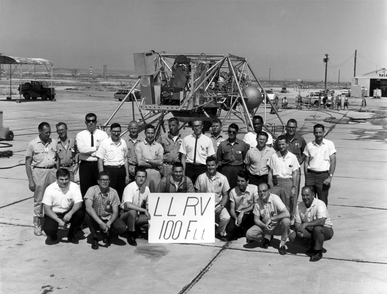
A group photo of the LLRV personnel following the program's 100th flight. The photo was taken at South Base, and was near the hangar first used by the original NACA group, at what was then called Muroc. When Apollo planning was underway in 1960, NASA was looking for a simulator to profile the descent to the moon's surface. Three concepts surfaced: an electronic simulator, a tethered device, and the ambitious Dryden contribution, a free-flying vehicle. All three became serious projects, but eventually the NASA Flight Research Center's (FRC) Landing Research Vehicle (LLRV) became the most significant one. Hubert M. Drake is credited with originating the idea, while Donald Bellman and Gene Matranga were senior engineers on the project, with Bellman, the project manager. Simultaneously, and independently, Bell Aerosystems Company, Buffalo, N.Y., a company with experience in vertical takeoff and landing (VTOL) aircraft, had conceived a similar free-flying simulator and proposed their concept to NASA headquarters. NASA Headquarters put FRC and Bell together to collaborate. The challenge was; to allow a pilot to make a vertical landing on Earth in a simulated moon environment, one sixth of the Earth's gravity and with totally transparent aerodynamic forces in a "free flight" vehicle with no tether forces acting on it. Built of tubular aluminum like a giant four-legged bedstead, the vehicle was to simulate a lunar landing profile from around 1500 feet to the moon's surface. To do this, the LLRV had a General Electric CF-700-2V turbofan engine mounted vertically in gimbals, with 4200 pounds of thrust. The engine, using JP-4 fuel, got the vehicle up to the test altitude and was then throttled back to support five-sixths of the vehicle's weight, simulating the reduced gravity of the moon. Two hydrogen-peroxide lift rockets with thrust that could be varied from 100 to 500 pounds handled the LLRV's rate of descent and horizontal translations. Sixteen smaller hydrogen-peroxide r
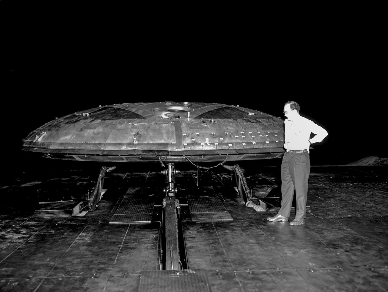
Avrocar with ground board and variable height struts and no tail. Can see focusing ring that controlled the peripheral jet.
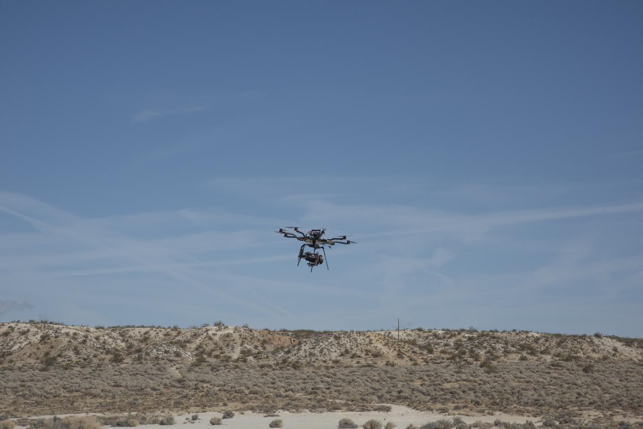
The Alta 8 remotely piloted aircraft flies above Rosamond North Lakebed at NASA's Armstrong Flight Research Center in Edwards, California. The Resilient Autonomy project used these flights to collect data with the Nav Module hardware and software developed by NASA's Jet Propulsion Laboratory in Pasadena, California.
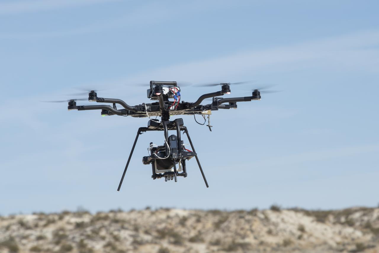
The Alta 8 remotely piloted aircraft hovers above Rosamond North Lakebed in March 2021 at NASA's Armstrong Flight Research Center in Edwards, California. The Resilient Autonomy project used these flights to collect data with the Nav Module hardware and software developed by NASA's Jet Propulsion Laboratory in Pasadena, California.