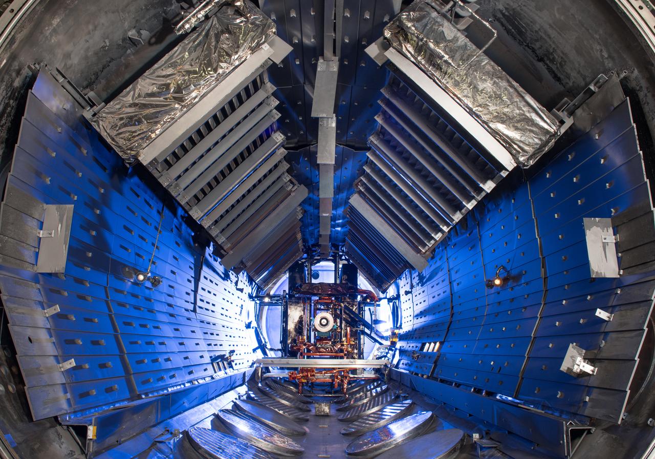
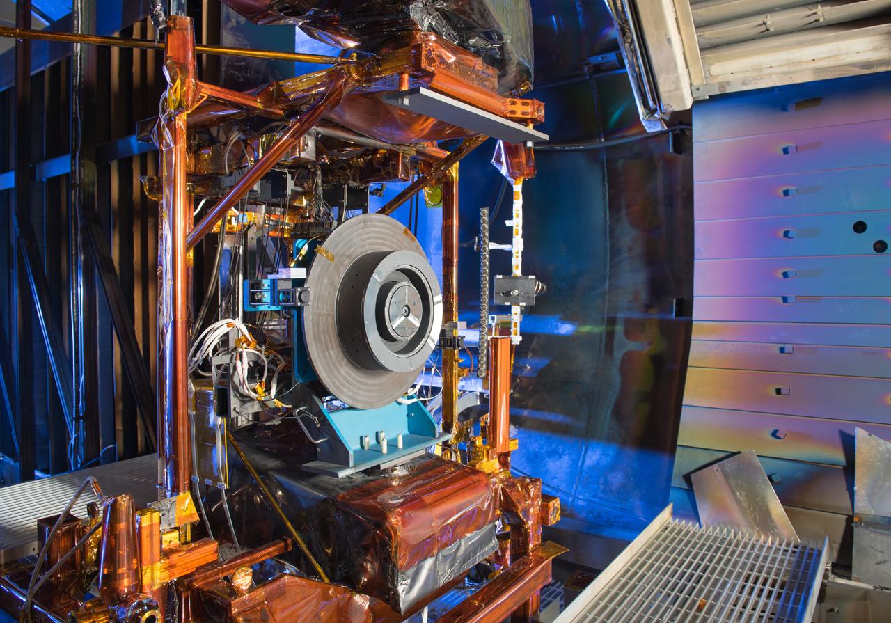
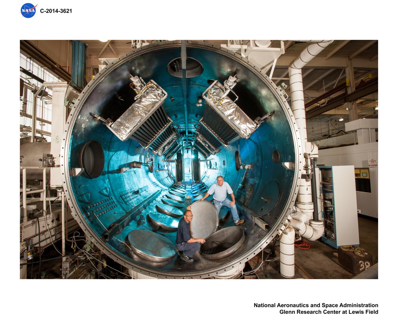
Advanced Electric Propulsion Systems Contract, Technology Demonstration Unit, TDU-3 Checkout Test Hardware Installed in Vacuum Facility 5, VF-5
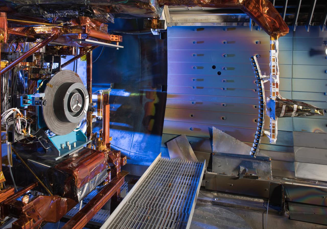
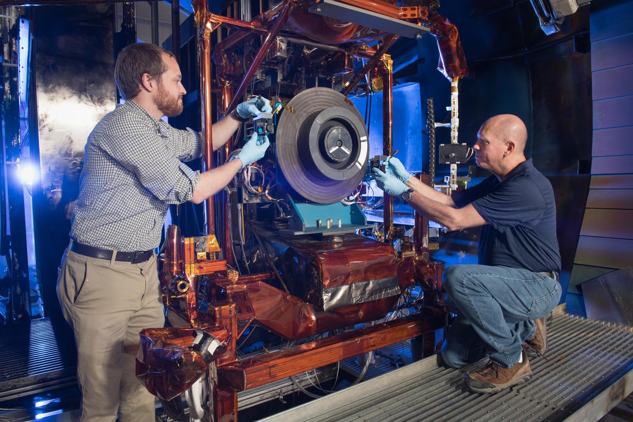
Advanced Electric Propulsion Systems Contract, Technology Demonstration Unit, TDU-3 Checkout Test Hardware Installed in Vacuum Facility 5, VF-5
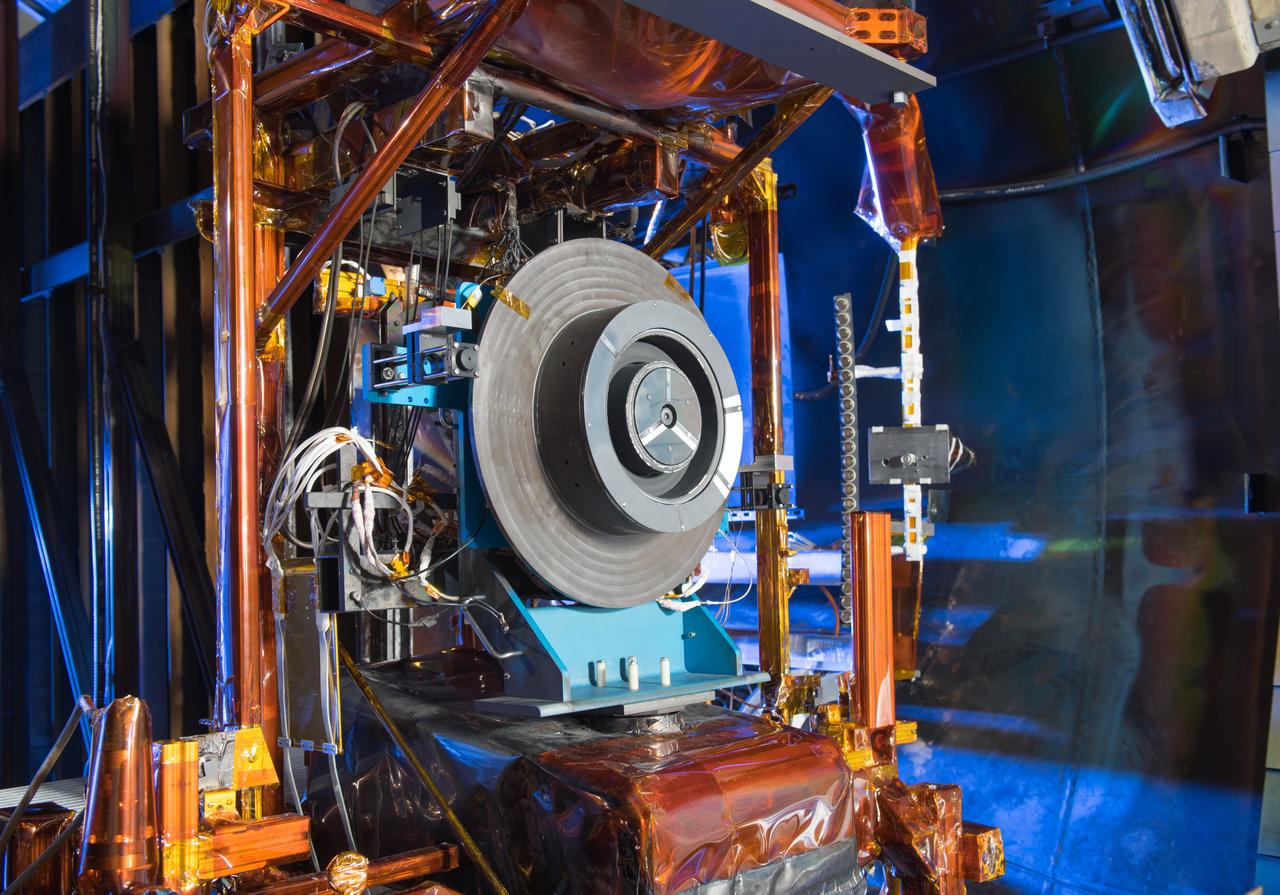
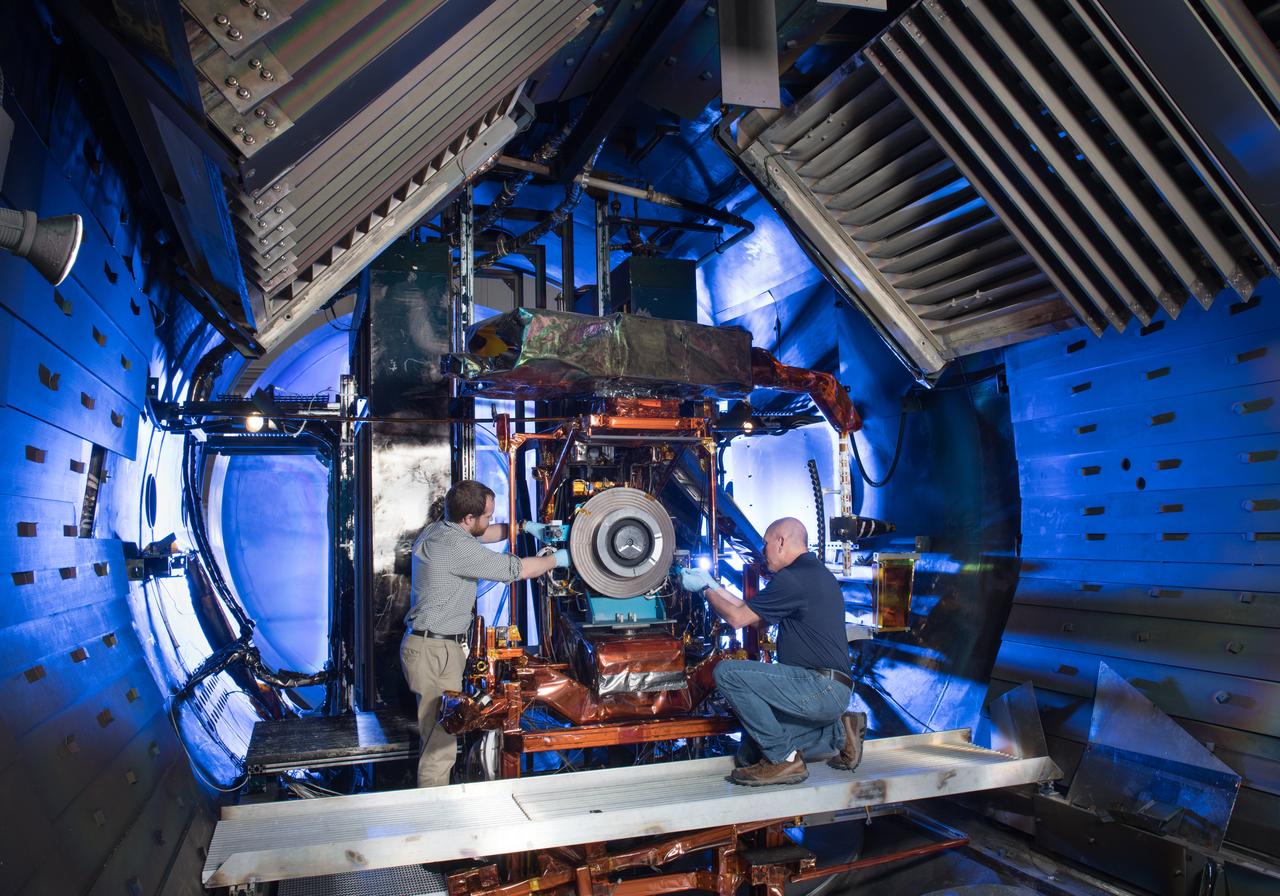
Advanced Electric Propulsion Systems Contract, Technology Demonstration Unit, TDU-3 Checkout Test Hardware Installed in Vacuum Facility 5, VF-5
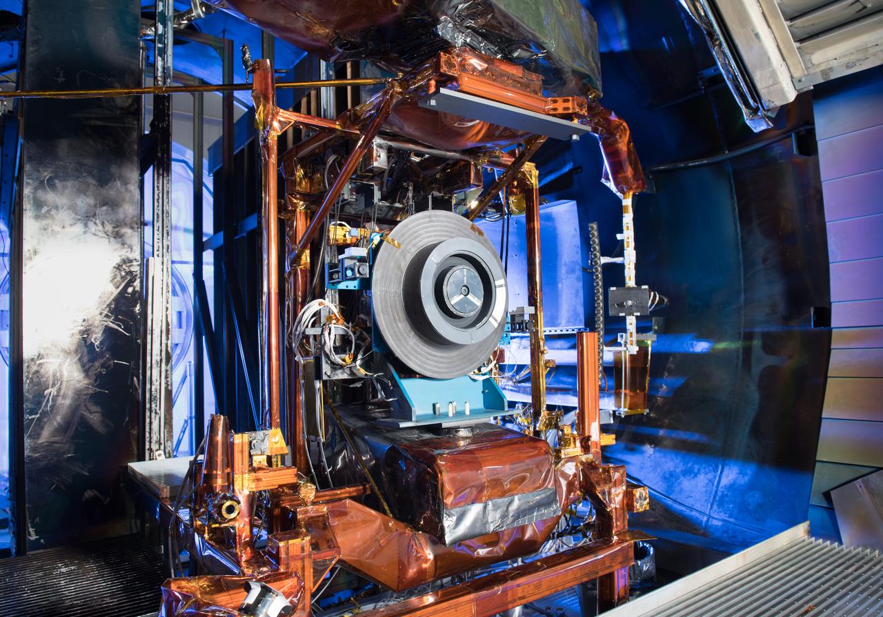
Advanced Electric Propulsion Systems Contract, Technology Demonstration Unit, TDU-3 Checkout Test Hardware Installed in Vacuum Facility 5, VF-5
Advanced Electric Propulsion Systems Contract, Technology Demonstration Unit, TDU-3 Checkout Test Hardware Installed in Vacuum Facility 5, VF-5
Advanced Electric Propulsion Systems Contract, Technology Demonstration Unit, TDU-3 Checkout Test Hardware Installed in Vacuum Facility 5, VF-5
Advanced Electric Propulsion Systems Contract, Technology Demonstration Unit, TDU-3 Checkout Test Hardware Installed in Vacuum Facility 5, VF-5
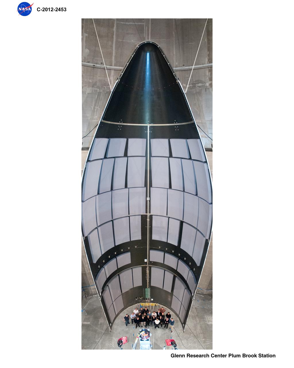
Space Power Facility at Plum Brook Station, RUAG Ariane 5 Shroud Separation Tests. GRC has the world's largest vacuum chamber in the world. This world class facility is host to many space launch vehicle systems tests from customer's in this country and from around the world. Shown here is the post test of a successful rocket shroud separation test. The shroud, or top of a rocket, is jettisoned into two halves with explosive charges to allow the payload to be exposed for deployment. The payload, often time is a satellite, would be sitting atop the center white section shown in the middle of the photo. This photo was taken from on top of the rocket holding the payload and both halves of the rocket shroud looking down at one of the shroud halves and the test crew at the bottom.
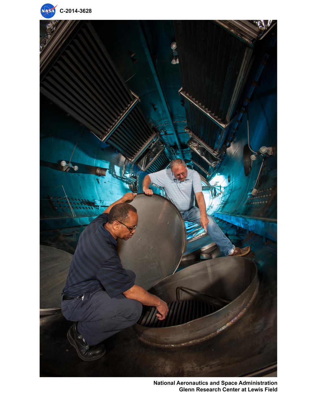
Vacuum Facility 5
Vacuum Facility 5
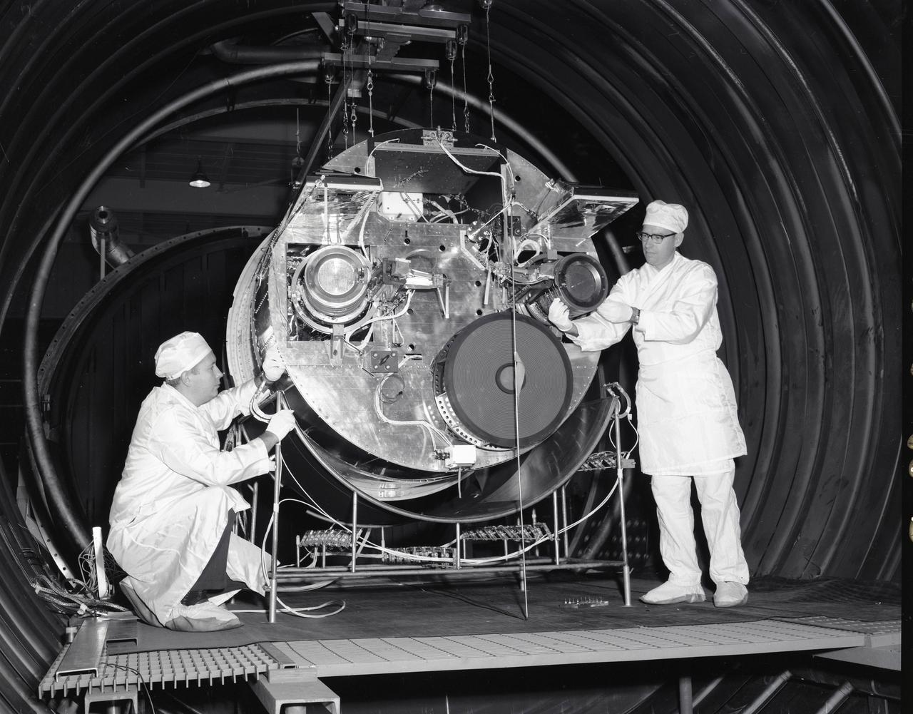
SPACE ELECTRIC ROCKET TEST, SERT II IN TANK 5
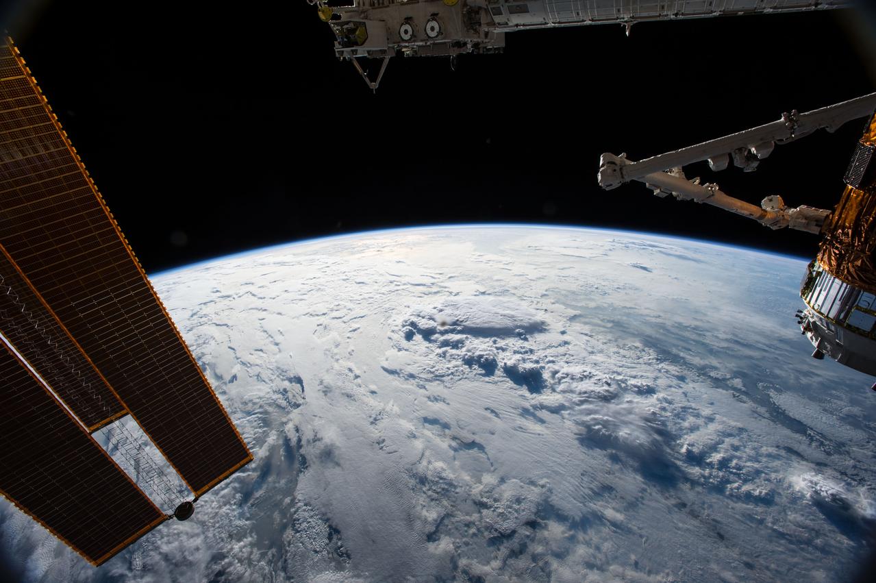
ISS045E028447 (09/25/2015) --- Sunlight shines on the International Space Station as it flies approximately 250 miles over the Earth’s surface. One of the station’s massive solar arrays is visible left, responsible for generating power for all of the various station systems. The Japanese Exposed Facility is visible at the top of the image where experiments are exposed to the vacuum and environment of space. The Japanese HTV-5 cargo vehicle is seen on the right while still docked to the Earth-facing port of the Harmony module; the vehicle was unberthed and released on Sept. 28, 2015.
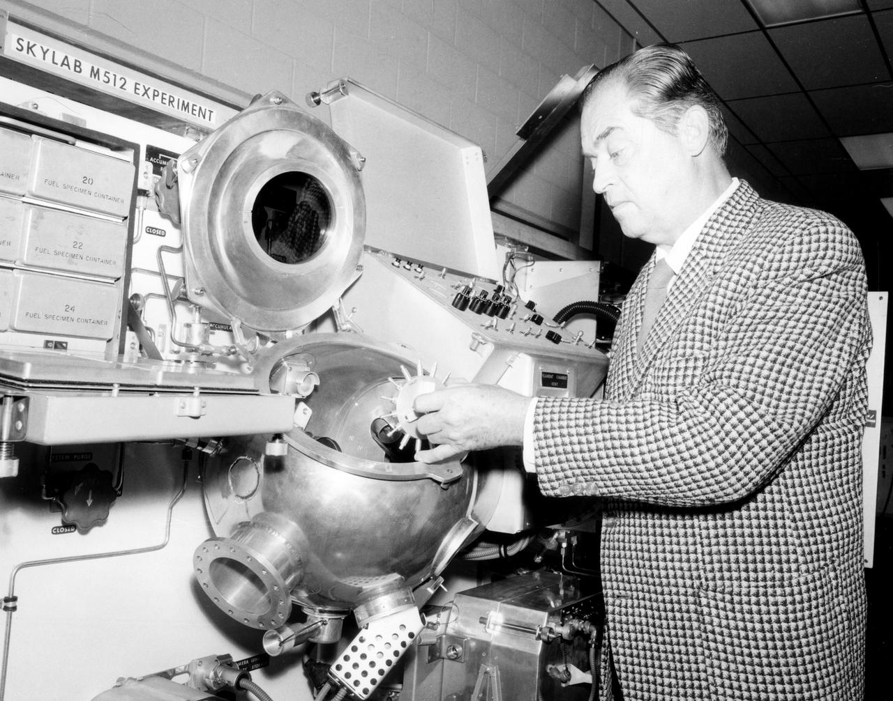
Hans F. Wuenscher, assistant director for Advanced Space Projects Engineering Laboratory at Marshall Space Flight Center (MSFC), examined the facility to be used by Skylab astronauts in performing a number of experiments in material science and manufacturing in space. The equipment shown here is a duplicate of the M512 Experiment hardware flown in the Multiple Docking Adapter section of the Sky lab. This equipment, itself an experiment, was be used for conducting 5 other experiments in the round vacuum chamber. Inside was a cavity which held the M518 Multipurpose Electric Furnace, a facility which was used for conducting other experiments. In all, a total of 17 experiments were conducted using this facility and furnace.
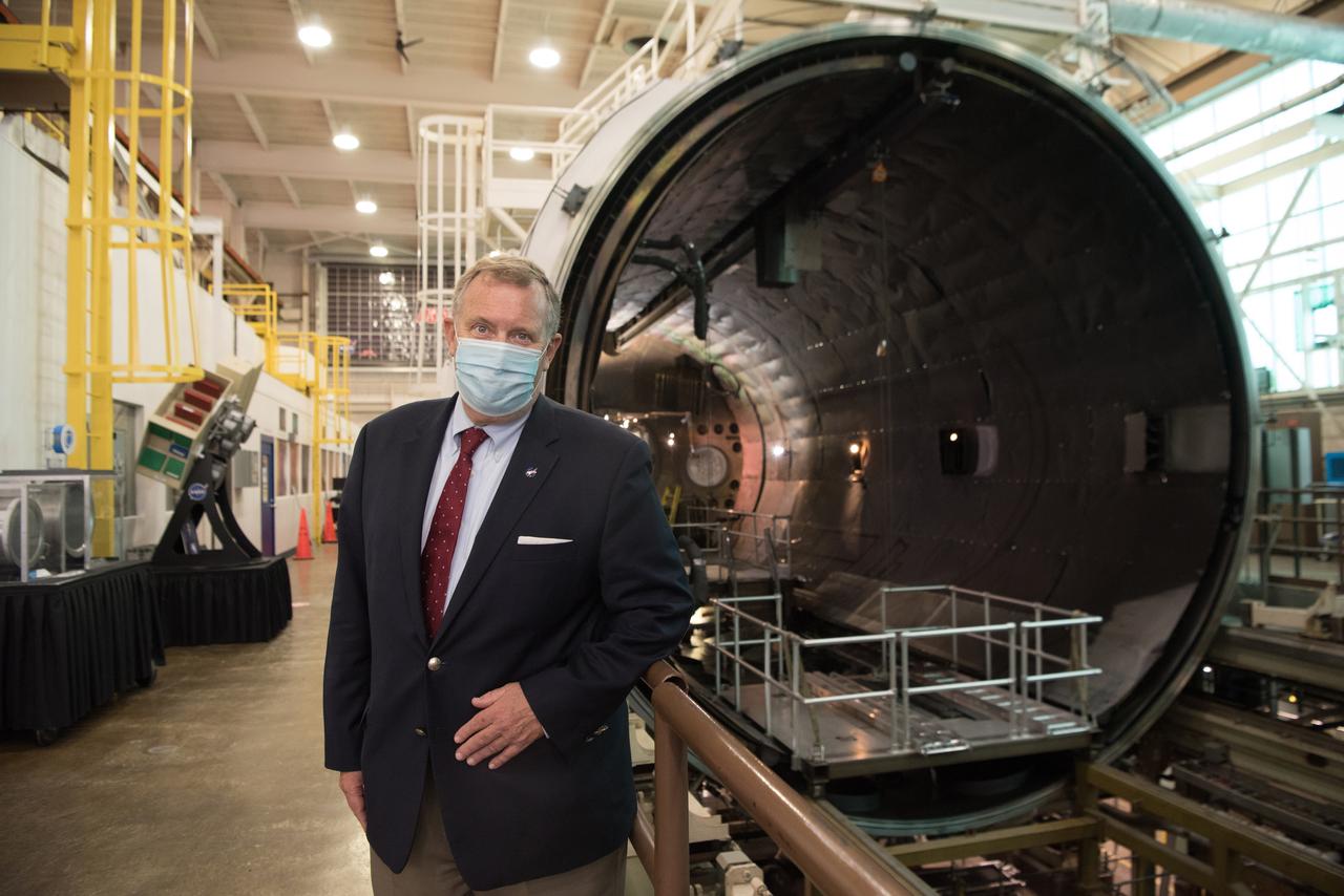
Visit to GRC by the Deputy Administrator, James Morhard
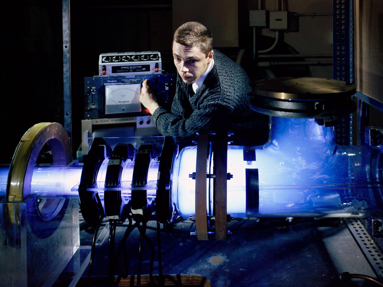
Raymond Palmer, of the Electromagnetic Propulsion Division’s Plasma Flow Section, adjusts the traveling magnetic wave plasma engine being operated in the Electric Power Conversion at the National Aeronautics and Space Administration (NASA) Lewis Research Center. During the 1960s Lewis researchers were exploring several different methods of creating electric propulsion systems, including the traveling magnetic wave plasma engine. The device operated similarly to alternating-current motors, except that a gas, not a solid, was used to conduct the electricity. A magnetic wave induced a current as it passed through the plasma. The current and magnetic field pushed the plasma in one direction. Palmer and colleague Robert Jones explored a variety of engine configurations in the Electric Propulsion Research Building. The engine is seen here mounted externally on the facility’s 5-foot diameter and 16-foot long vacuum tank. The four magnetic coils are seen on the left end of the engine. The researchers conducted two-minute test runs with varying configurations and used of both argon and xenon as the propellant. The Electric Propulsion Research Building was built in 1942 as the Engine Propeller Research Building, often called the Prop House. It contained four test cells to study large reciprocating engines with their propellers. After World War II, the facility was modified to study turbojet engines. By the 1960s, the facility was modified again for electric propulsion research and given its current name.
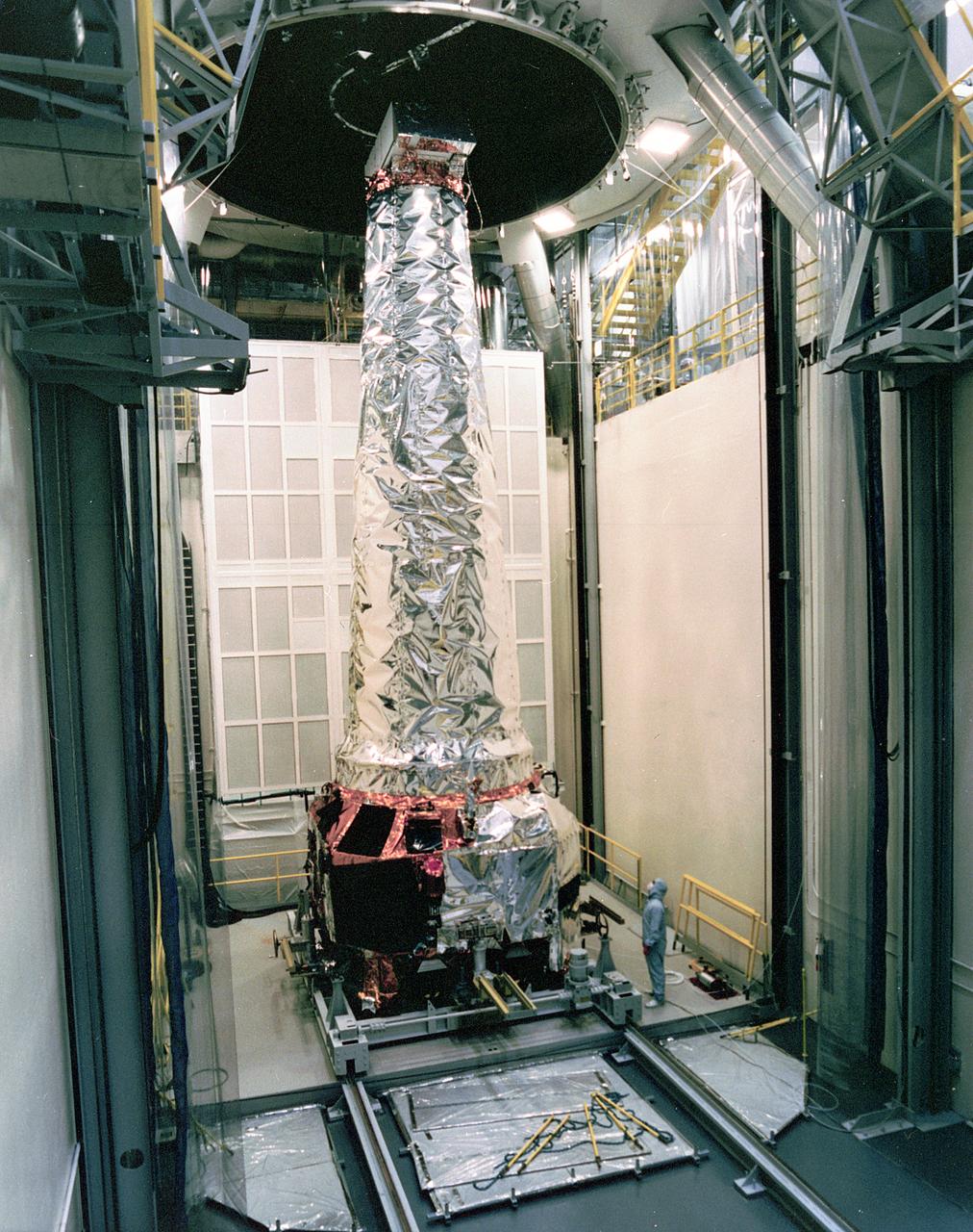
This photograph shows a TRW technician inspecting the completely assembled Chandra X-ray Observatory (CXO) in the Thermal Vacuum Chamber at TRW Space and Electronics Group of Redondo Beach, California. The CXO is formerly known as the Advanced X-Ray Astrophysics Facility (AXAF), which was renamed in honor of the late Indian-American Astronomer, Subrahmanyan Chandrasekhar in 1999. The CXO will help astronomers worldwide better understand the structure and evolution of the universe by studying powerful sources of x-rays such as exploding stars, matter falling into black holes and other exotic celestial objects. X-ray astronomy can only be done from space because Earth's atmosphere blocks x-rays from reaching the surface. The Observatory provides images that are 50 times more detailed than previous x-ray missions. At more than 45 feet in length and weighing more than 5 tons, it will be one of the largest objects ever placed in Earth orbit by the Space Shuttle. TRW, Inc. was the prime contractor and assembled and tested the observatory for NASA. The CXO program is managed by the Marshall Space Flight Center. The Observatory was launched on July 22, 1999 aboard the Space Shuttle Columbia, STS-93 mission. (Image courtesy of TRW)