NASA’s X-59 Quiet SuperSonic Technology airplane undergoes structural stress tests at a Lockheed Martin facility in Fort Worth, Texas. Lockheed Martin Aeronautics Company - Fort Worth - Chris Hanoch Subject: X-59 - Various Angles in Test Fixture FP#: 21-03420 POC: Analiese Smith, Chris Higgins Other info: X-59 in Fort Worth, testing; high angle shots in fixture 1-10-22
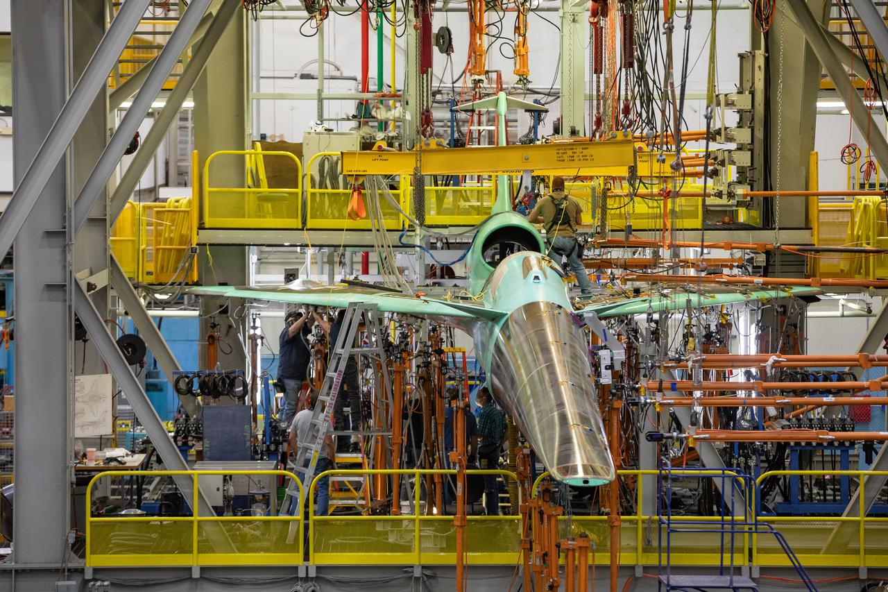
NASA’s X-59 undergoes a structural stress test at Lockheed Martin’s facility at Fort Worth, Texas. The X-59 is a one-of-a-kind airplane designed to fly at supersonic speeds without making a startling sonic boom sound for the communities below. This is part of NASA’s Quesst mission, which plans to help enable supersonic air travel over land.

NASA’s X-59 undergoes a structural stress test at Lockheed Martin’s facility at Fort Worth, Texas. The X-59 is a one-of-a-kind airplane designed to fly at supersonic speeds without making a startling sonic boom sound for the communities below. This is part of NASA’s Quesst mission, which plans to help enable supersonic air travel over land.
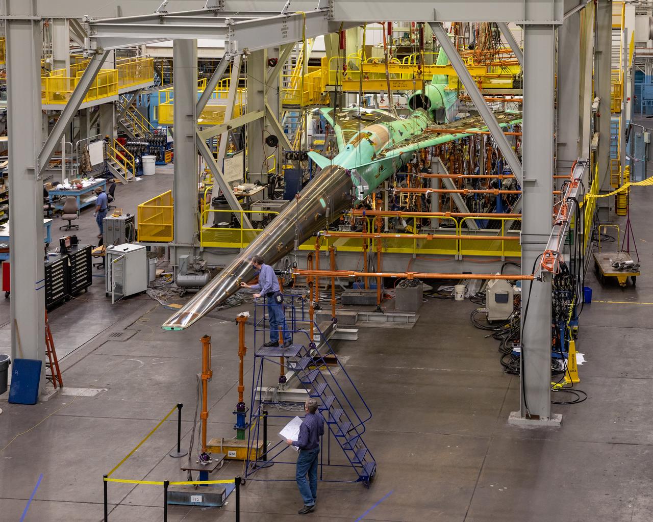
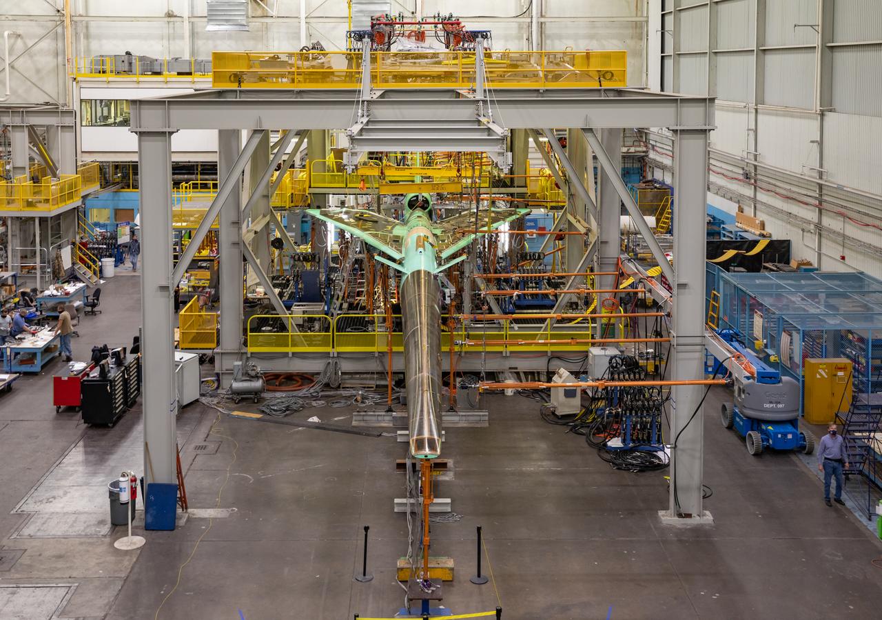
NASA’s X-59 undergoes a structural stress test at Lockheed Martin’s facility in Fort Worth, Texas. The X-59’s nose makes up one third of the aircraft, at 38-feet in length. The X-59 is a one-of-a-kind airplane designed to fly at supersonic speeds without making a startling sonic boom sound for the communities below. This is part of NASA’s Quesst mission, which plans to help enable supersonic air travel over land
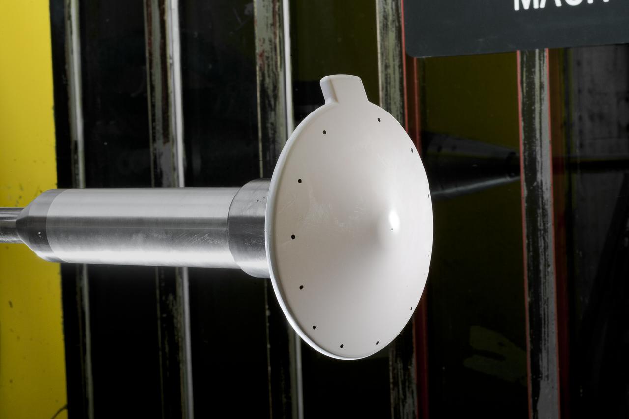
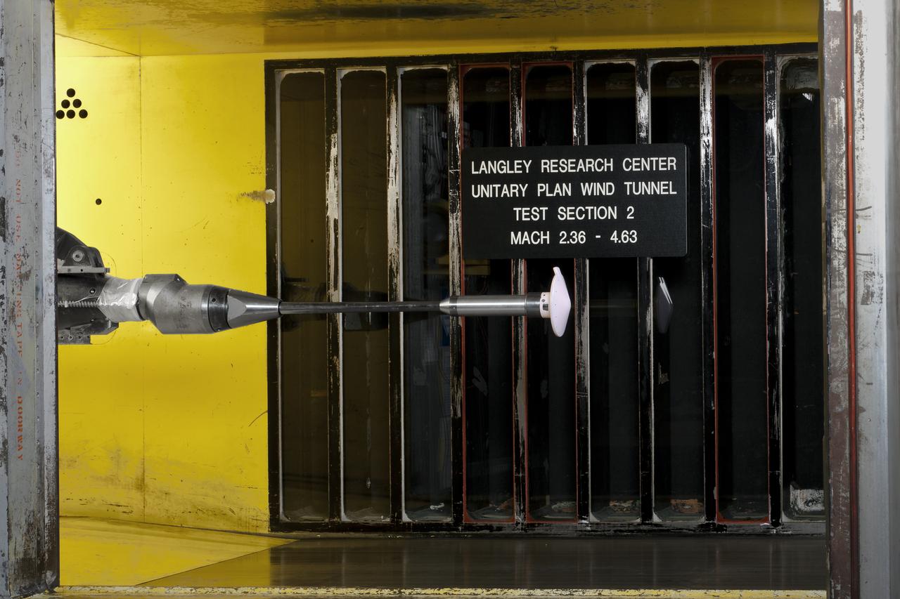
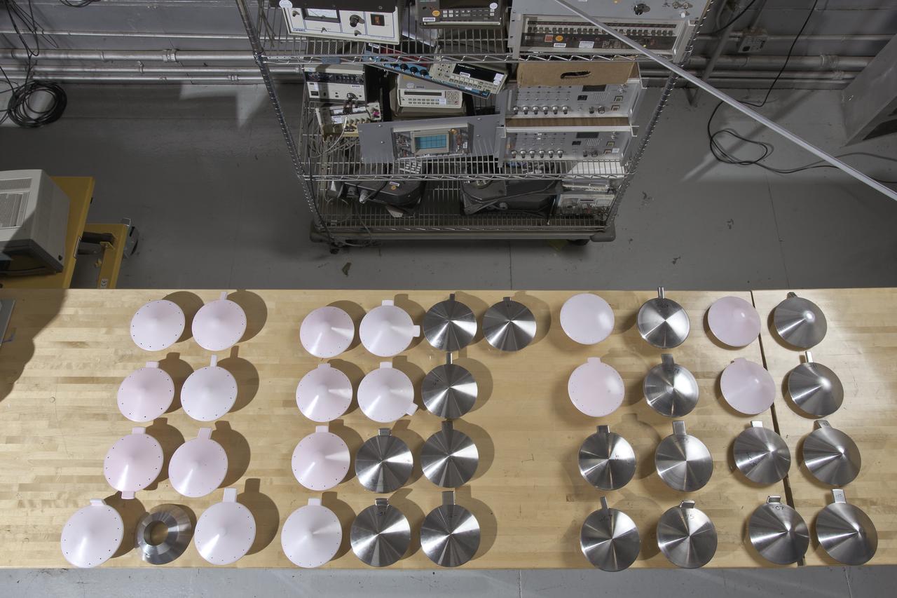
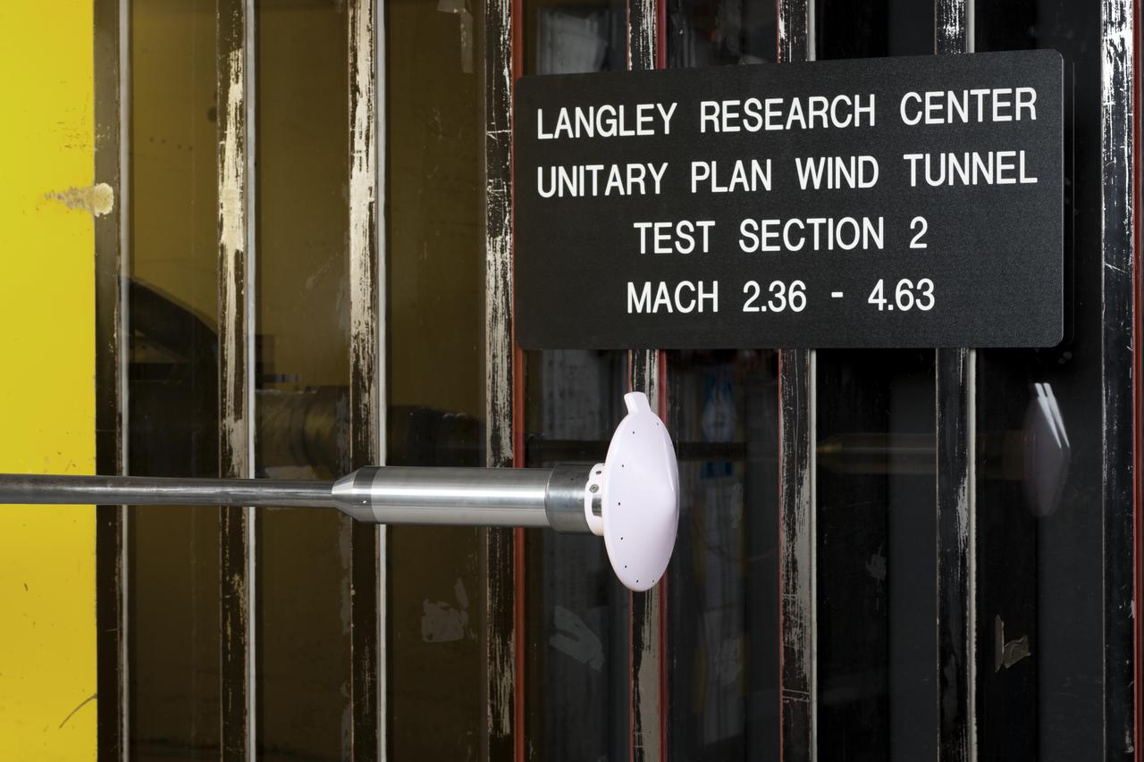
Test 1875 in Unitary Plan Wind Tunnel (UPWT) HIADS TTPM: Trim Tab study on various cone angled heat shields (TTPM) Technology Technical Performance Metric (HIADS) Hypersonic inflatable aerodynamic decelerators
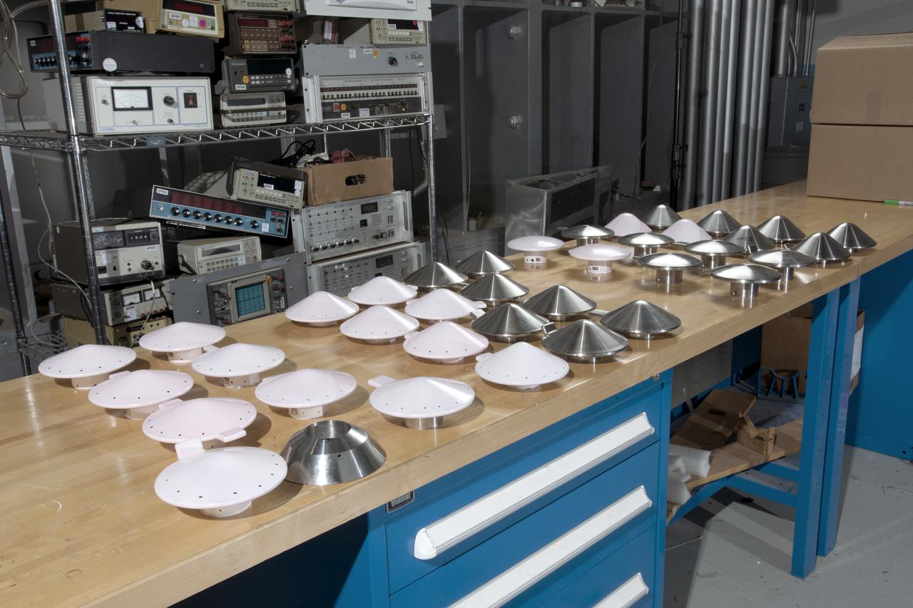
Test 1875 in Unitary Plan Wind Tunnel (UPWT) HIADS TTPM: Trim Tab study on various cone angled heat shields (TTPM) Technology Technical Performance Metric (HIADS) Hypersonic inflatable aerodynamic decelerators
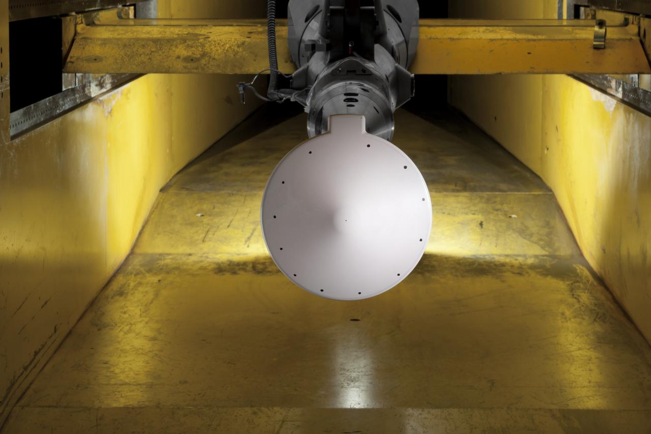
Test 1875 in Unitary Plan Wind Tunnel (UPWT) HIADS TTPM: Trim Tab study on various cone angled heat shields (TTPM) Technology Technical Performance Metric (HIADS) Hypersonic inflatable aerodynamic decelerators
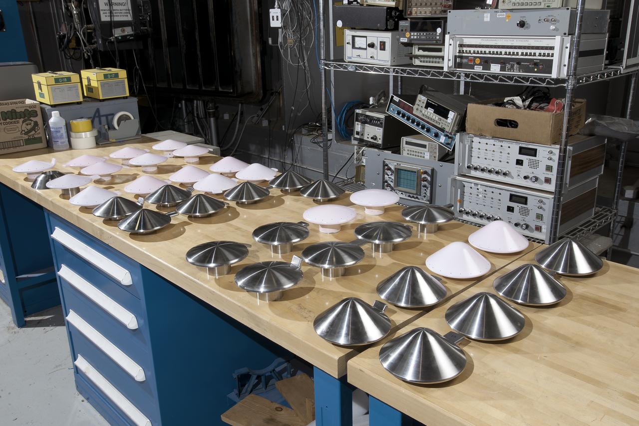
Test 1875 in Unitary Plan Wind Tunnel (UPWT) HIADS TTPM: Trim Tab study on various cone angled heat shields (TTPM) Technology Technical Performance Metric (HIADS) Hypersonic inflatable aerodynamic decelerators
Test 1875 in Unitary Plan Wind Tunnel (UPWT) HIADS TTPM: Trim Tab study on various cone angled heat shields (TTPM) Technology Technical Performance Metric (HIADS) Hypersonic inflatable aerodynamic decelerators
Test 1875 in Unitary Plan Wind Tunnel (UPWT) HIADS TTPM: Trim Tab study on various cone angled heat shields (TTPM) Technology Technical Performance Metric (HIADS) Hypersonic inflatable aerodynamic decelerators
Test 1875 in Unitary Plan Wind Tunnel (UPWT) HIADS TTPM: Trim Tab study on various cone angled heat shields (TTPM) Technology Technical Performance Metric (HIADS) Hypersonic inflatable aerodynamic decelerators
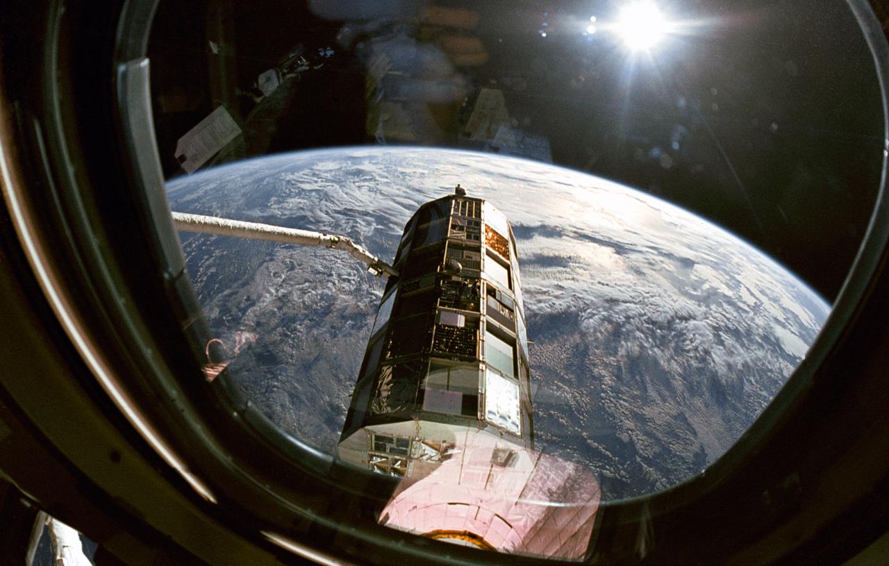
This view taken through overhead window W7 on Columbia's, Orbiter Vehicle (OV) 102's, aft flight deck shows the Long Duration Exposure Facility (LDEF) in the grasp of the remote manipulator system (RMS) during STS-32 retrieval activities. Other cameras at eye level were documenting the bus-sized spacecraft at various angles as the RMS manipulated LDEF for a lengthy photo survey. The glaring celestial body in the upper left is the sun with the Earth's surface visible below.

ISS002-E-5657 (16 April 2001) --- San Diego, California, and the California border with Mexico were photographed with a digital still camera by the Expedition Two crew onboard the International Space Station (ISS). A 105mm lens was used for this frame. Other pictures taken in this April 16, 2001 series show different angles of the metropolitan area and utilize various lenses.
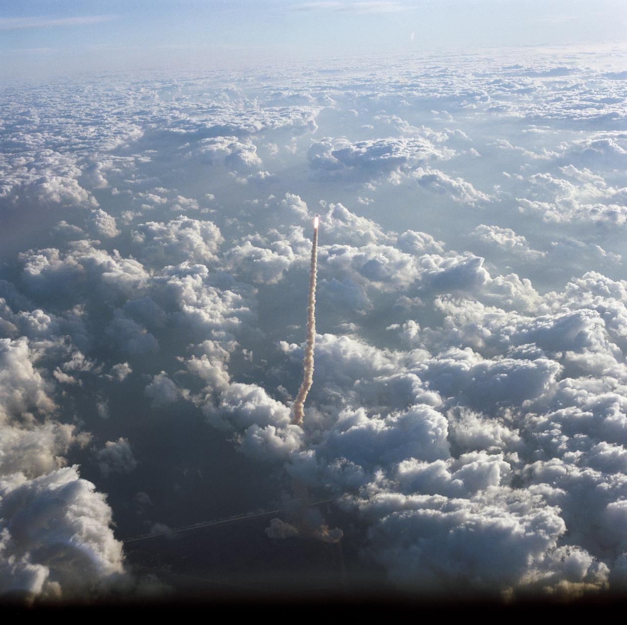
51A-90015 (8 Nov. 1984) --- John W. Young, who has seen many launches from various angles, used a handheld camera to record this scene of the very early phase of launch for NASA's space shuttle Discovery. Young was flying the NASA shuttle training aircraft (STA). Shuttle Discovery (51A) is seen as a spot of light at the top of a column of smoke outlined among the dense cloud cover. Photo credit: NASA
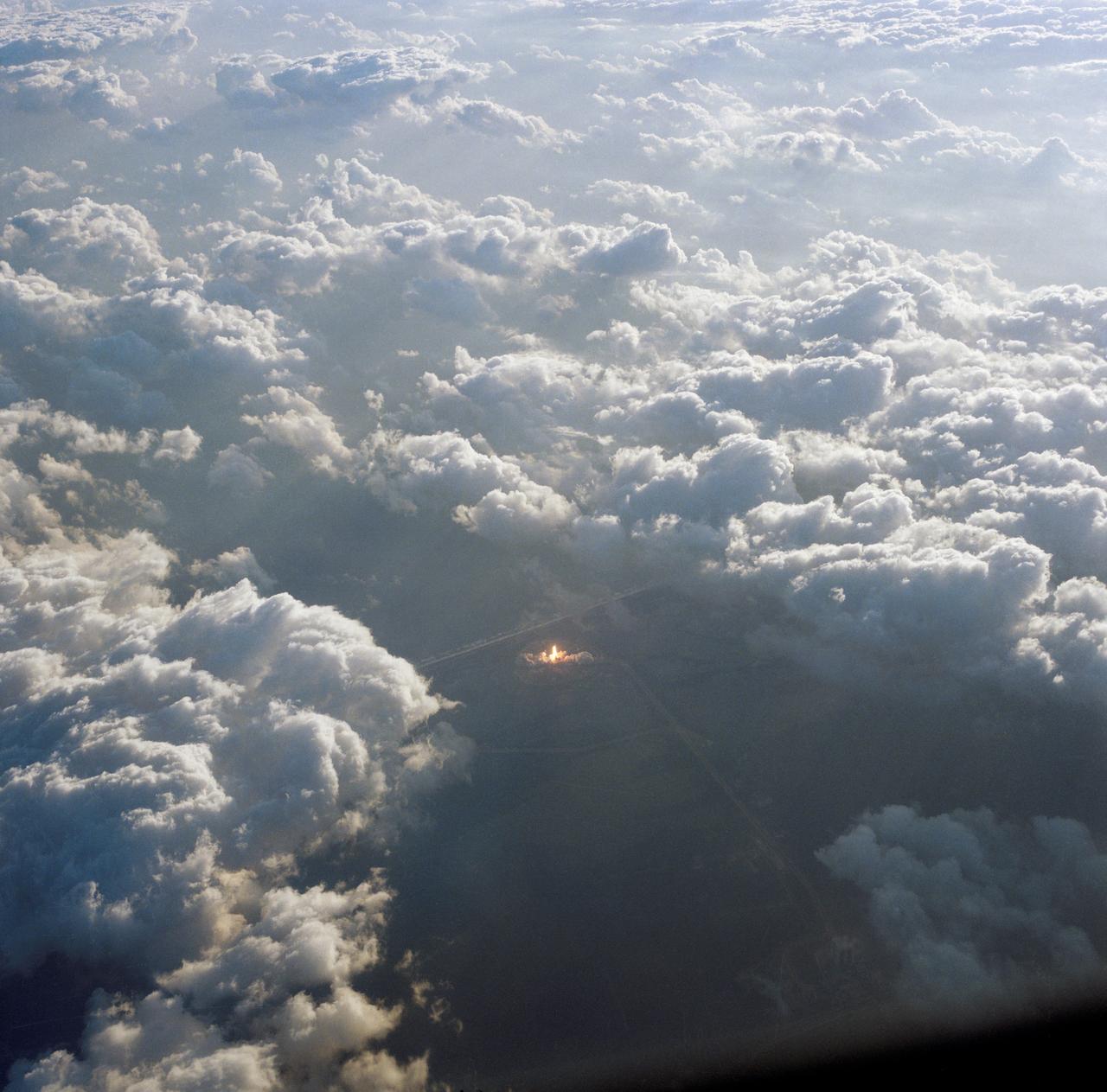
51A-90014 (8 Nov. 1984) --- John W. Young, who has seen many launches from various angles, used a handheld camera to record this scene of the very early phase of launch for NASA's space shuttle Discovery. Young was flying the NASA shuttle training aircraft (STA). The launch pad can be seen as a bright spot in the center of a mass of clouds. Photo credit: NASA

Enceladus' intriguing south-polar jets are viewed from afar, backlit by sunlight while the moon itself glows softly in reflected Saturn-shine. Observations of the jets taken from various viewing geometries provide different insights into these remarkable features. Cassini has gathered a wealth of information in the hopes of unraveling the mysteries of the subsurface ocean that lurks beneath the moon's icy crust. This view looks toward the Saturn-facing hemisphere of Enceladus (313 miles or 504 kilometers across). North is up. The image was taken in visible light with the Cassini spacecraft narrow-angle camera on April 13, 2017. The view was acquired at a distance of approximately 502,000 miles (808,000 kilometers) from Enceladus and at a sun-Enceladus-spacecraft, or phase, angle of 176 degrees. Image scale is 3 miles (5 kilometers) per pixel. https://photojournal.jpl.nasa.gov/catalog/PIA21338
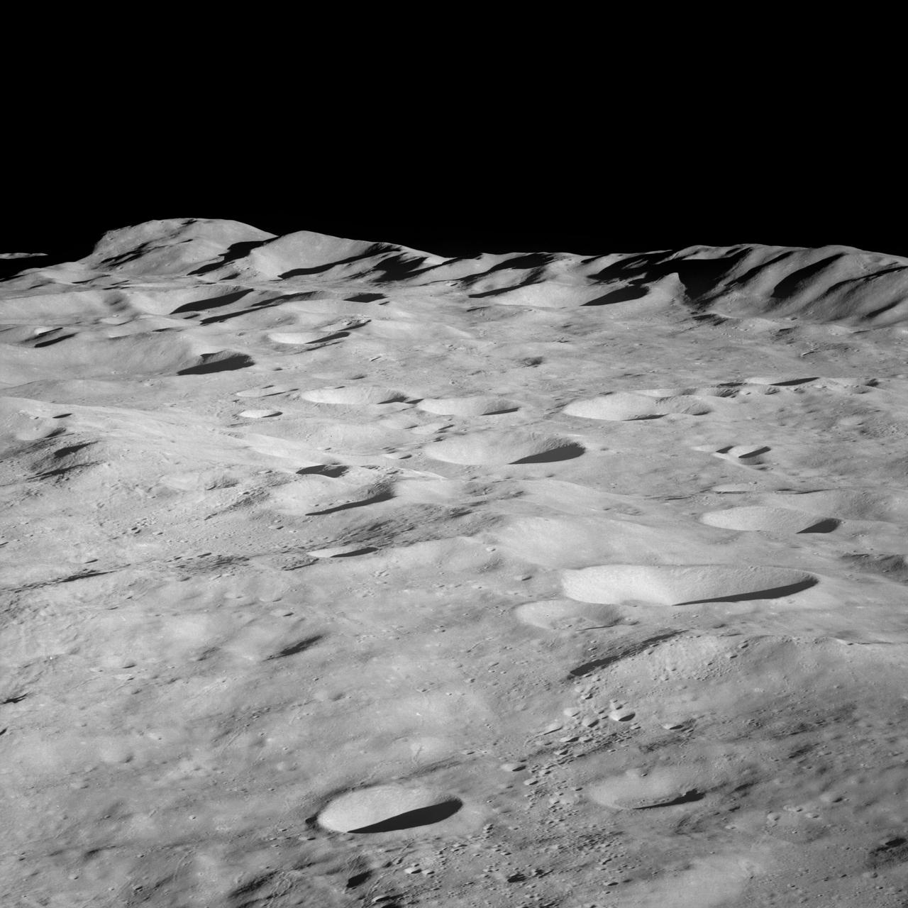
Apollo 8,Moon,Target of Opportunity (T/O) 10, Various targets. Latitude 18 degrees South,Longitude 163.50 degrees West. Camera Tilt Mode: High Oblique. Direction: South. Sun Angle 12 degrees. Original Film Magazine was labeled E. Camera Data: 70mm Hasselblad; F-Stop: F-5.6; Shutter Speed: 1/250 second. Film Type: Kodak SO-3400 Black and White,ASA 40. Other Photographic Coverage: Lunar Orbiter 1 (LO I) S-3. Flight Date: December 21-27,1968.
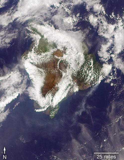
On May 3, 2018, a new eruption began at a fissure of the Kilauea volcano on the Island of Hawaii. Kilauea is the most active volcano in the world, having erupted almost continuously since 1983. Advancing lava and dangerous sulfur dioxide gas have forced thousands of residents in the neighborhood of Leilani Estates to evacuate. A number of homes have been destroyed, and no one can say how soon the eruption will abate and evacuees can return home. On May 6, 2018, at approximately 11 a.m. local time, the Multi-angle Imaging SpectroRadiometer (MISR) instrument on NASA's Terra satellite captured this view of the island as it passed overhead. Much of the island was shrouded by clouds, including the fissure on its eastern point. However, an eruption plume is visible streaming southwest over the ocean. The MISR instrument is unique in that it has nine cameras that view Earth at different angles: one pointing downward, four at various angles in the forward direction, and four in the backward direction. This image shows the view from one of MISR's forward-pointing cameras (60 degrees), which shows the plume more distinctly than the near-vertical views. The information from the images acquired at different view angles is used to calculate the height of the plume, results of which are superimposed on the right-hand image. The top of the plume near the fissure is at approximately 6,500 feet (2,000 meters) altitude, and the height of the plume decreases as it travels south and west. These relatively low altitudes mean that the ash and sulfur dioxide remained near the ground, which can cause health issues for people on the island downwind of the eruption. The "Ocean View" air quality monitor operated by the Clean Air Branch of the State of Hawaii Department of Health recorded a concentration of 18 μg/m3 of airborne particles less than 2.5 micrometers in diameter at 11 a.m. local time. This amount corresponds to an air quality rating of "moderate" and supports the MISR results indicating that ash was most likely present at ground level on this side of the island. These data were acquired during Terra orbit 97780. An annotated version is available at https://photojournal.jpl.nasa.gov/catalog/PIA22451
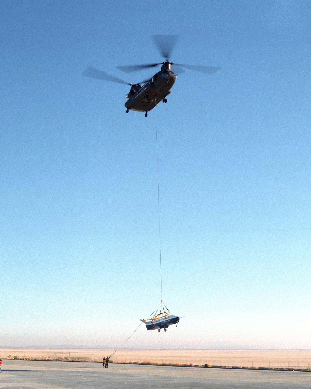
Ground crewmen help guide the alignment of the X-40 technology demonstrator as the experimental craft is gently lowered to the ground by a U.S. Army CH-47 Chinook cargo helicopter following a captive-carry test flight at NASA's Dryden Flight Research Center, Edwards, California. The X-40 is an unpowered 82 percent scale version of the X-37, a Boeing-developed spaceplane designed to demonstrate various advanced technologies for development of future lower-cost access to space vehicles. The X-37 will be carried into space aboard a space shuttle and then released to perform various maneuvers and a controlled re-entry through the Earth's atmosphere to an airplane-style landing on a runway, controlled entirely by pre-programmed computer software. Following a series of captive-carry flights, the X-40 made several free flights from a launch altitude of about 15,000 feet above ground, gliding to a fully autonomous landing. The captive carry flights helped verify the X-40's navigation and control systems, rigging angles for its sling, and stability and control of the helicopter while carrying the X-40 on a tether.
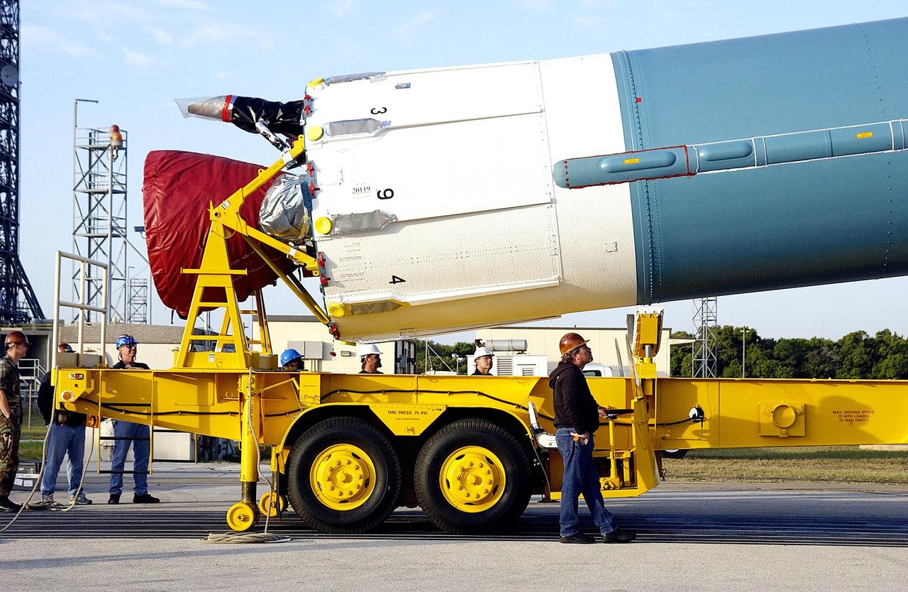
KENNEDY SPACE CENTER, FLA. - The angle of the first stage of the Delta II rocket on its transporter indicates it is being lifted to vertical for erection on Pad 17-A on Cape Canaveral Air Force Station. The Delta will launch the Mars Exploration Rover (MER-A) vehicle. The MER Mission consists of two identical rovers designed to cover roughly 110 yards each Martian day over various terrain. Each rover will carry five scientific instruments that will allow it to search for evidence of liquid water that may have been present in the planet's past. Identical to each other, the rovers will land at different regions of Mars. Launch date for this first of NASA's two Mars Exploration Rover missions is scheduled no earlier than June 6.

This image from NASA's Juno spacecraft provides a never-before-seen perspective on Jupiter's south pole. The JunoCam instrument acquired the view on August 27, 2016, when the spacecraft was about 58,700 miles (94,500 kilometers) above the polar region. At this point, the spacecraft was about an hour past its closest approach, and fine detail in the south polar region is clearly resolved. Unlike the equatorial region's familiar structure of belts and zones, the poles are mottled by clockwise and counterclockwise rotating storms of various sizes, similar to giant versions of terrestrial hurricanes. The south pole has never been seen from this viewpoint, although the Cassini spacecraft was able to observe most of the polar region at highly oblique angles as it flew past Jupiter on its way to Saturn in 2000. http://photojournal.jpl.nasa.gov/catalog/PIA21032
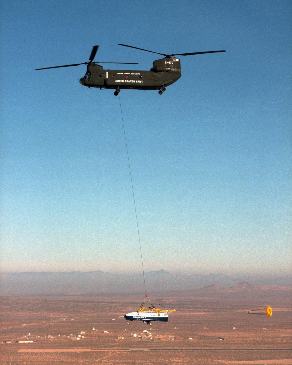
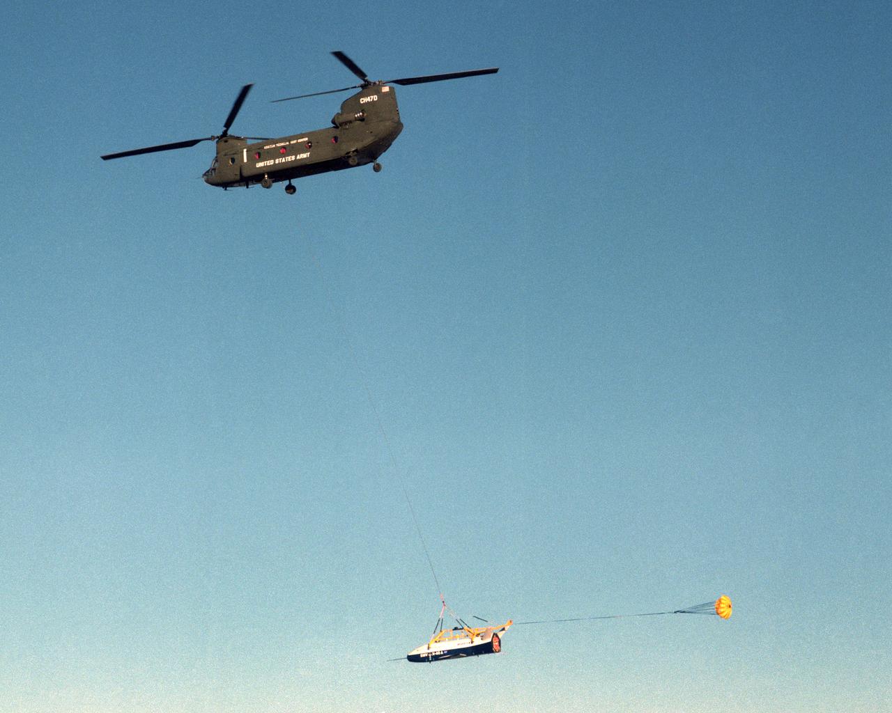
With a small stabilization parachute trailing behind, the X-40 sub-scale technology demonstrator is suspended under a U.S. Army CH-47 Chinook cargo helicopter during a captive-carry test flight at NASA's Dryden Flight Research Center, Edwards, California. The captive carry flights are designed to verify the X-40's navigation and control systems, rigging angles for its sling, and stability and control of the helicopter while carrying the X-40 on a tether. Following a series of captive-carry flights, the X-40 made free flights from a launch altitude of about 15,000 feet above ground, gliding to a fully autonomous landing. The X-40 is an unpowered 82 percent scale version of the X-37, a Boeing-developed spaceplane designed to demonstrate various advanced technologies for development of future lower-cost access to space vehicles.
The X-40 sub-scale technology demonstrator is suspended under a U.S. Army CH-47 Chinook cargo helicopter during a captive-carry test flight at NASA's Dryden Flight Research Center, Edwards, California. The captive carry flights are designed to verify the X-40's navigation and control systems, rigging angles for its sling, and stability and control of the helicopter while carrying the X-40 on a tether. Following a series of captive-carry flights, the X-40 made free flights from a launch altitude of about 15,000 feet above ground, gliding to a fully autonomous landing. The X-40 is an unpowered 82 percent scale version of the X-37, a Boeing-developed spaceplane designed to demonstrate various advanced technologies for development of future lower-cost access to space vehicles.
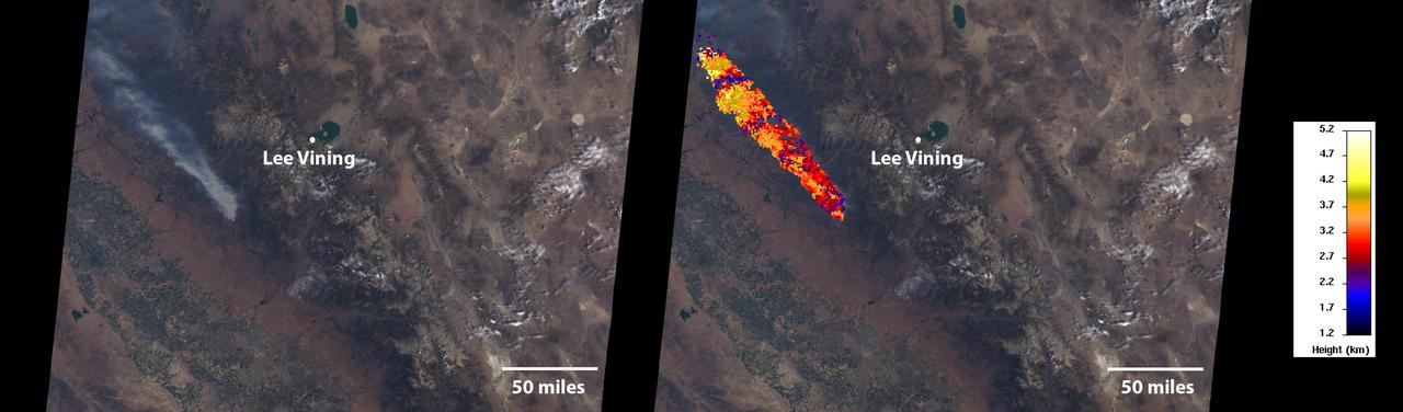
On July 24, 2022, the Multi-angle Imaging SpectroRadiometer (MISR) instrument aboard NASA's Terra satellite captured data on a smoke plume from the Oak Fire burning near Yosemite National Park in California. As of July 26, the Oak Fire had scorched more than 18,000 acres (7,284 hectares) and was 26% contained, with thousands of residents under evacuation orders. Hot, dry air, along with vegetation parched from years of drought, fueled the fire's rapid spread. The MISR instrument contains nine cameras that view Earth at different angles. The left panel in the image above shows an image captured by MISR's nadir (downward-pointing) camera of a smoke plume from the fire. Although the fire was burning near Yosemite at the time, it wasn't a threat to the national park. The panel on the right indicates the height of various parts of the plume as measured by several of MISR's cameras. Yellow areas are higher than the red and blue regions in the smoke plume. The height of the plume top near the active fire was about 17,060 feet (5,200 meters), or roughly 3 miles (nearly 5 kilometers). In general, higher-altitude plumes transport smoke greater distances from the source, impacting communities downwind. On the day the images were captured, unhealthy-to-hazardous air quality was reported in the area around Lake Tahoe and Truckee, about 125 miles (200 kilometers) north of the fire. MISR researchers calculate smoke plume height using the publicly available MISR INteractive eXplorer (MINX) software tool. https://photojournal.jpl.nasa.gov/catalog/PIA24907
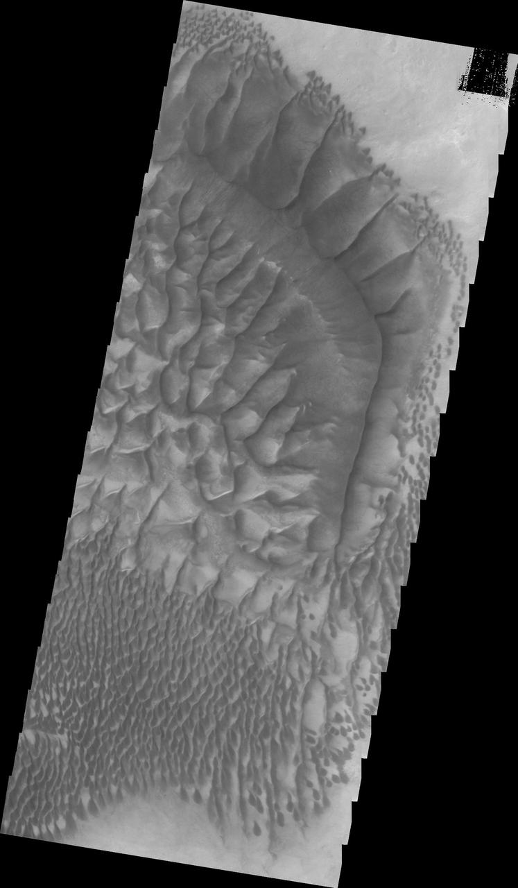
Dunes cover the majority of this image of Rabe Crater. As the dunes are created by wind action the forms of the dunes record the wind direction. Dunes will have a long low angle component and a short high angle side. The steep side is called the slip face. The wind blows up the long side of the dune. In this VIS image the slip faces are illuminated more than the longer side. In this part of the crater the winds were generally moving from the lower right corner of the image towards the upper left. Rabe Crater is 108 km (67 miles) across. Craters of similar size often have flat floors. Rabe Crater has some areas of flat floor, but also has a large complex pit occupying a substantial part of the floor. The interior fill of the crater is thought to be layered sediments created by wind and or water action. The pit is eroded into this material. The eroded materials appear to have stayed within the crater forming a large sand sheet with surface dune forms as well as individual dunes where the crater floor is visible. The dunes also appear to be moving from the upper floor level into the pit. The Odyssey spacecraft has spent over 15 years in orbit around Mars, circling the planet more than 69000 times. It holds the record for longest working spacecraft at Mars. THEMIS, the IR/VIS camera system, has collected data for the entire mission and provides images covering all seasons and lighting conditions. Over the years many features of interest have received repeated imaging, building up a suite of images covering the entire feature. From the deepest chasma to the tallest volcano, individual dunes inside craters and dune fields that encircle the north pole, channels carved by water and lava, and a variety of other feature, THEMIS has imaged them all. For the next several months the image of the day will focus on the Tharsis volcanoes, the various chasmata of Valles Marineris, and the major dunes fields. We hope you enjoy these images! Orbit Number: 35105 Latitude: -43.8533 Longitude: 34.8802 Instrument: VIS Captured: 2009-11-12 19:59 https://photojournal.jpl.nasa.gov/catalog/PIA22141
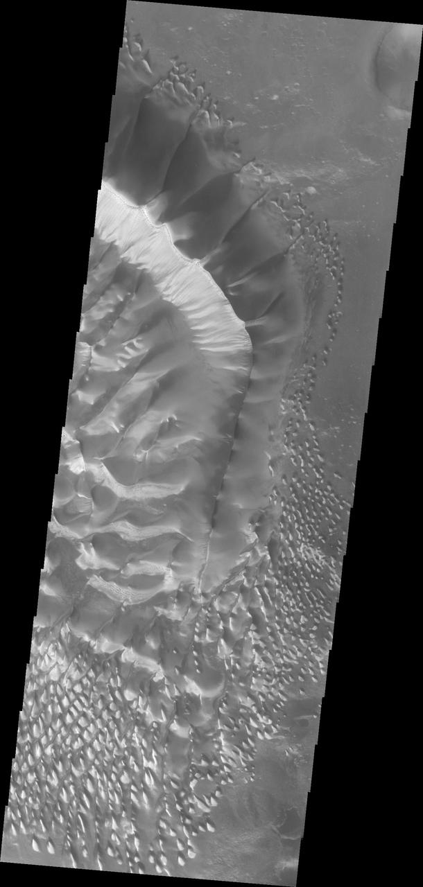
This image shows the central part of the dune field on the floor of Russell Crater, including the large dune ridge. Comparing this image to yesterday's you will see a significant difference in appearance. This image was collected at a higher incidence angle, so the sun is at a different angle to the surface. Russell Crater is located in Noachis Terra. A spectacular dune ridge and other dune forms on the crater floor have caused extensive imaging. The Odyssey spacecraft has spent over 15 years in orbit around Mars, circling the planet more than 69000 times. It holds the record for longest working spacecraft at Mars. THEMIS, the IR/VIS camera system, has collected data for the entire mission and provides images covering all seasons and lighting conditions. Over the years many features of interest have received repeated imaging, building up a suite of images covering the entire feature. From the deepest chasma to the tallest volcano, individual dunes inside craters and dune fields that encircle the north pole, channels carved by water and lava, and a variety of other feature, THEMIS has imaged them all. For the next several months the image of the day will focus on the Tharsis volcanoes, the various chasmata of Valles Marineris, and the major dunes fields. We hope you enjoy these images! Orbit Number: 39723 Latitude: -54.4434 Longitude: 13.0526 Instrument: VIS Captured: 2010-11-28 01:47 https://photojournal.jpl.nasa.gov/catalog/PIA21807
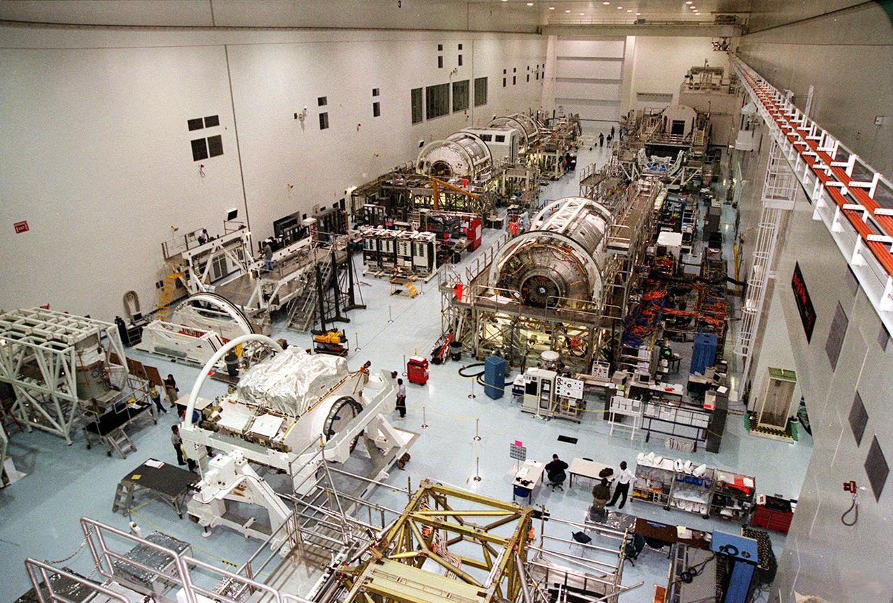
A wide-angle view of the floor of the Space Station Processing Facility. The floor is filled with racks and hardware for processing and testing the various components of the International Space Station (ISS). At the bottom left is the Zenith-1 (Z-1) Truss, the cornerstone truss of the Space Station. The Z-1 Truss was officially turned over to NASA from The Boeing Co. on July 31. The truss is scheduled to fly in Space Shuttle Discovery's payload pay on STS-92 targeted for launch Oct. 5, 2000. The Z-1 is considered a cornerstone truss because it carries critical components of the Station's attitude, communications, thermal and power control systems as well as four control moment gyros, high and low gain antenna systems, and two plasma contactor units used to disperse electrical charge build-ups. The Z-1 truss and a Pressurized Mating Adapter (PMA-3), also flying to the Station on the same mission, will be the first major U.S. elements flown to the ISS aboard the Shuttle since the launch of the Unity element in December 1998. The large module in the center of the floor is the U.S. Lab, Destiny. Expected to be a major feature in future research, Destiny will provide facilities for biotechnology, fluid physics, combustion, and life sciences research. It is scheduled to be launched on mission STS-98 (no date determined yet for launch)
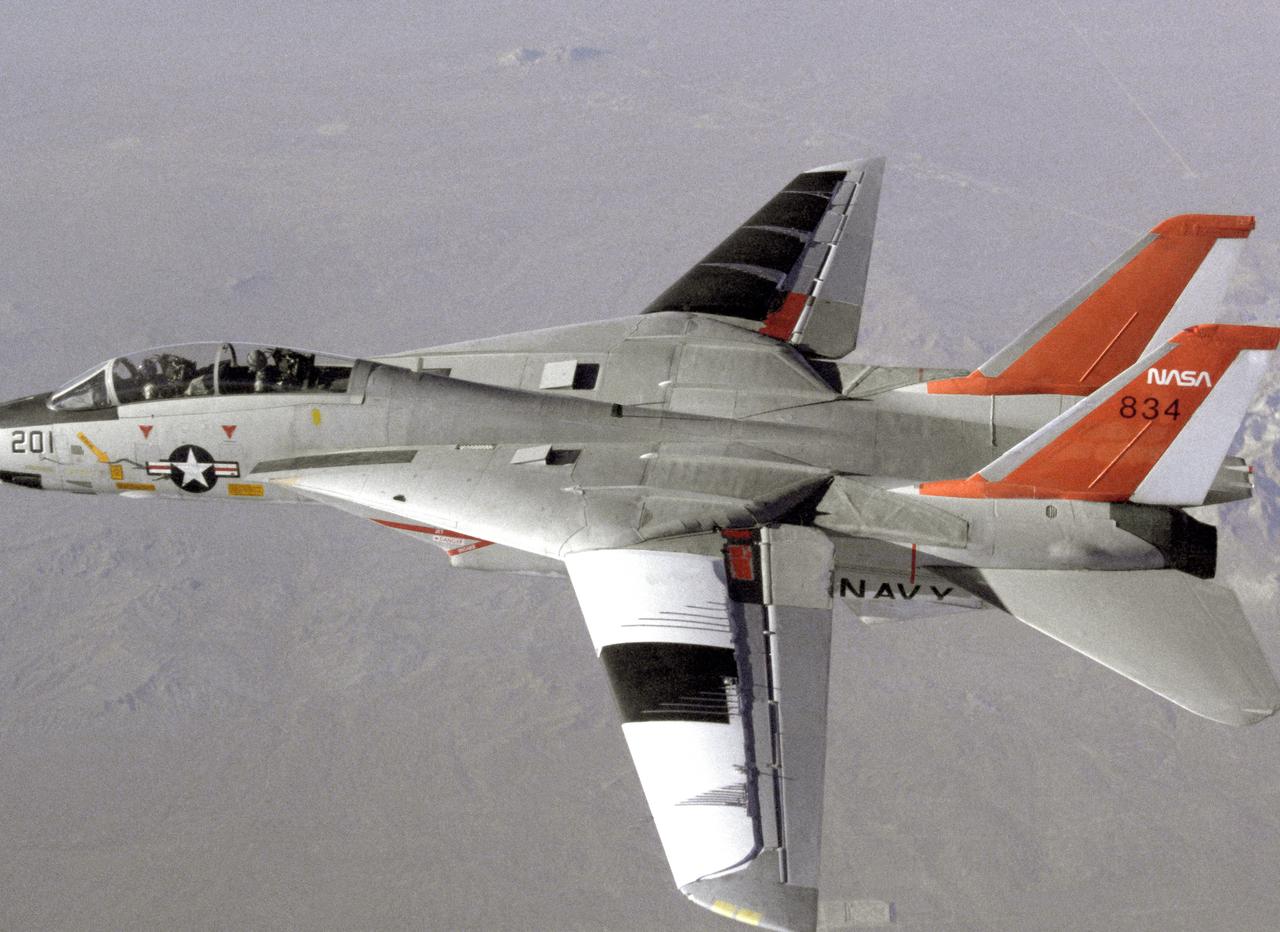
NASA 834, an F-14 Navy Tomcat, seen here in flight, was used at Dryden in 1986 and 1987 in a program known as the Variable-Sweep Transition Flight Experiment (VSTFE). This program explored laminar flow on variable sweep aircraft at high subsonic speeds. An F-14 aircraft was chosen as the carrier vehicle for the VSTFE program primarily because of its variable-sweep capability, Mach and Reynolds number capability, availability, and favorable wing pressure distribution. The variable sweep outer-panels of the F-14 aircraft were modified with natural laminar flow gloves to provide not only smooth surfaces but also airfoils that can produce a wide range of pressure distributions for which transition location can be determined at various flight conditions and sweep angles. Glove I, seen here installed on the upper surface of the left wing, was a "cleanup" or smoothing of the basic F-14 wing, while Glove II was designed to provide specific pressure distributions at Mach 0.7. Laminar flow research continued at Dryden with a research program on the NASA 848 F-16XL, a laminar flow experiment involving a wing-mounted panel with millions of tiny laser cut holes drawing off turbulent boundary layer air with a suction pump.
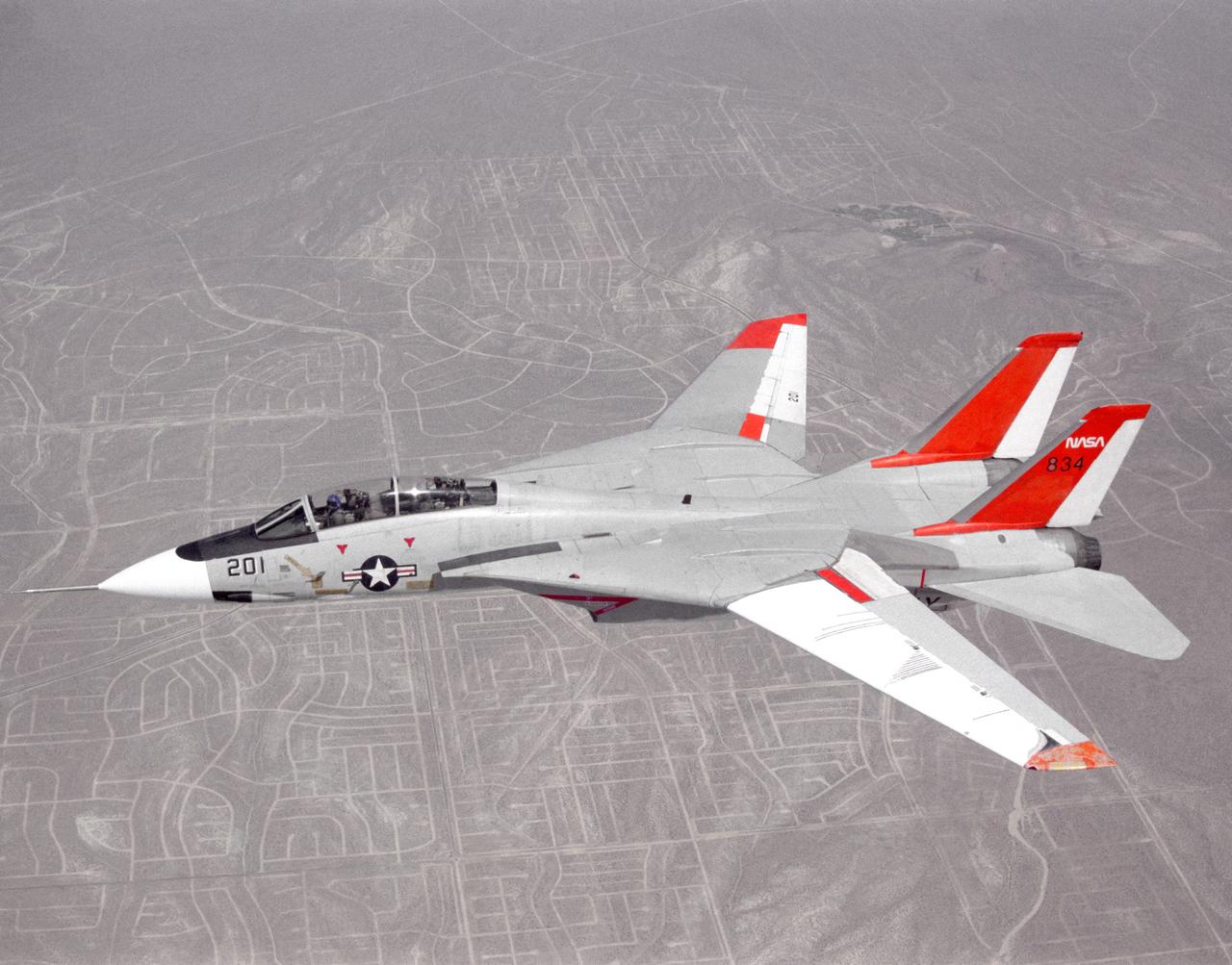
NASA 834, an F-14 Navy Tomcat, seen here in flight, was used at Dryden in 1986 and 1987 in a program known as the Variable-Sweep Transition Flight Experiment (VSTFE). This program explored laminar flow on variable sweep aircraft at high subsonic speeds. An F-14 aircraft was chosen as the carrier vehicle for the VSTFE program primarily because of its variable-sweep capability, Mach and Reynolds number capability, availability, and favorable wing pressure distribution. The variable sweep outer-panels of the F-14 aircraft were modified with natural laminar flow gloves to provide not only smooth surfaces but also airfoils that can produce a wide range of pressure distributions for which transition location can be determined at various flight conditions and sweep angles. Glove I, seen here installed on the upper surface of the left wing, was a "cleanup" or smoothing of the basic F-14 wing, while Glove II was designed to provide specific pressure distributions at Mach 0.7. Laminar flow research continued at Dryden with a research program on the NASA 848 F-16XL, a laminar flow experiment involving a wing-mounted panel with millions of tiny laser cut holes drawing off turbulent boundary layer air with a suction pump.

ISS036-S-001 (January 2012) --- The dynamic design of the Expedition 36 patch portrays the International Space Station?s (ISS) iconic solar arrays. The slanted angles denote a kinetic energy leading from the Earth in the lower right to the upper left tip of the triangular shape of the patch, representing the infinite scientific research, education, and long-duration spaceflight capabilities the ISS provides with each mission, as well as our goal for future exploration beyond the Space Station. The numbers 3 and 6 harmoniously intertwine to form expedition number 36 and its gray coloration signifies the unity and neutrality among all of the international partners of the ISS. The blue and gold color scheme of the patch represents the subtle way the central gold orbit wraps around the number 36 to form a trident at its lower right tip. The trident also symbolizes the sea, air, and land, all of which make up the Earth from where the trident originates in the design. The NASA insignia design for shuttle and space station flights is reserved for use by the astronauts and for other official use as the NASA Administrator may authorize. Public availability has been approved only in the form of illustrations by the various news media. When and if there is any change in this policy, which is not anticipated, it will be publicly announced. Photo credit: NASA
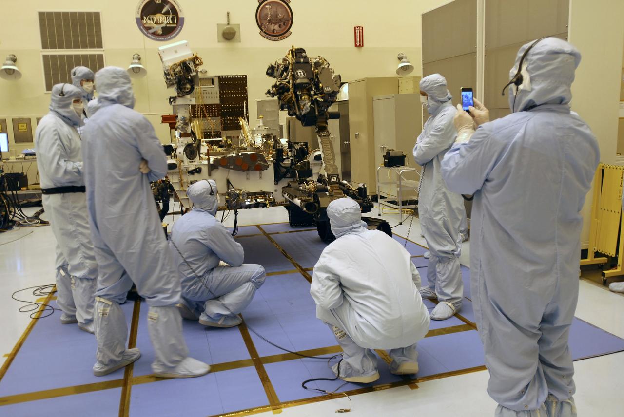
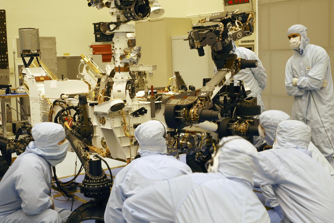
CAPE CANAVERAL, Fla. -- Under the watchful eyes of the spacecraft technicians in the Payload Hazardous Servicing Facility at NASA's Kennedy Space Center in Florida, the robotic arm of the Mars Science Laboratory (MSL) rover, Curiosity, moves into place against the body of the spacecraft. The arm will hold and maneuver instruments that will help scientists analyze Martian rocks and soil. Much like a human arm, the robotic arm has flexibility through shoulder, elbow, and wrist joints that permit the arm to extend, bend, and angle precisely against rocks and soil to grind away layers, take microscopic images and analyze their elemental composition. At the end of the arm is a hand-like structure, the turret, for holding various tools that can spin through a 350-degree turning range. A United Launch Alliance Atlas V-541 configuration will be used to loft MSL into space. Curiosity’s 10 science instruments are designed to search for evidence on whether Mars has had environments favorable to microbial life, including chemical ingredients for life. The unique rover will use a laser to look inside rocks and release its gasses so that the rover’s spectrometer can analyze and send the data back to Earth. MSL is scheduled to launch Nov. 25 from Space Launch Complex 41 on Cape Canaveral Air Force Station in Florida. For more information, visit http://www.nasa.gov/msl. Photo credit: NASA/Charisse Nahser
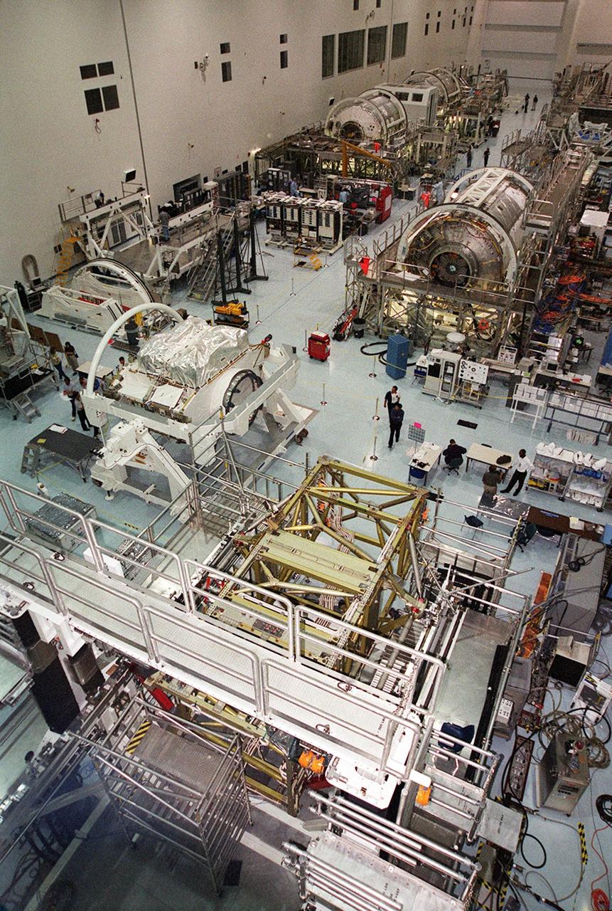
A wide-angle view of the floor of the Space Station Processing Facility. The floor is filled with racks and hardware for processing and testing the various components of the International Space Station (ISS). At center left is the Zenith-1 (Z-1) Truss, the cornerstone truss of the Space Station. The Z-1 Truss was officially turned over to NASA from The Boeing Co. on July 31. It is scheduled to fly in Space Shuttle Discovery's payload pay on STS-92 targeted for launch Oct. 5, 2000. The Z-1 is considered a cornerstone truss because it carries critical components of the Station's attitude, communications, thermal and power control systems as well as four control moment gyros, high and low gain antenna systems, and two plasma contactor units used to disperse electrical charge build-ups. The Z-1 truss and a Pressurized Mating Adapter (PMA-3), also flying to the Station on the same mission, will be the first major U.S. elements flown to the ISS aboard the Shuttle since the launch of the Unity element in December 1998. The large module in the upper right hand corner of the floor is the U.S. Lab, Destiny. Expected to be a major feature in future research, Destiny will provide facilities for biotechnology, fluid physics, combustion, and life sciences research. It is scheduled to be launched on mission STS-98 (no date determined yet for launch)
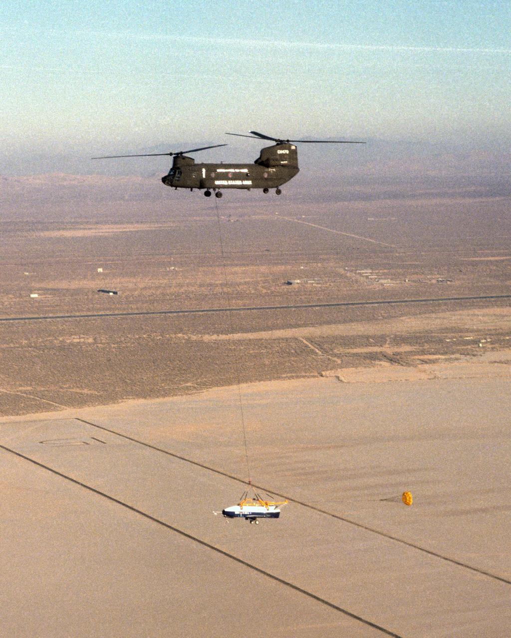
The X-40 sub-scale technology demonstrator and its U.S. Army CH-47 Chinook helicopter mothership fly over a dry lakebed runway during a captive-carry test flight from NASA's Dryden Flight Research Center, Edwards, California. The X-40 is attached to a sling which is suspended from the CH-47 by a 110-foot-long cable during the tests, while a small parachute trails behind to provide stability. The captive carry flights are designed to verify the X-40's navigation and control systems, rigging angles for its sling, and stability and control of the helicopter while carrying the X-40 on a tether. Following a series of captive-carry flights, the X-40 made free flights from a launch altitude of about 15,000 feet above ground, gliding to a fully autonomous landing. The X-40 is an unpowered 82 percent scale version of the X-37, a Boeing-developed spaceplane designed to demonstrate various advanced technologies for development of future lower-cost access to space vehicles.

HOUSTON, Texas -- STS119-S-001: The shape of the STS-119/15A patch comes from the shape of a solar array viewed at an angle. The International Space Station (ISS), which is the destination of the mission, is placed accordingly in the center of the patch just below the gold astronaut symbol. The gold solar array of the ISS highlights the main cargo and task of STS-119/15A -- the installation of the S6 truss segment and deployment of the S6's solar arrays, the last to be delivered to the ISS. Under the Japanese Kibo module, marked by a red circle, is the name of Japanese astronaut Koichi Wakata, who goes up to the ISS to serve as flight engineer representing JAXA. The rest of the STS-119/15A crew members are denoted on the outer band of the patch. The 17 white stars on the patch represent, in the crew's words, "the enormous sacrifice the crews of Apollo1, Challenger, and Columbia have given to our space program." The U.S. flag flowing into the Space Shuttle signifies the support the people of the United States have given our space program over the years, along with pride the U.S. astronauts have in representing the United States on this mission. The NASA insignia for design for Shuttle flights is reserved for use by the astronauts and for other official use as the NASA Administrator may authorize. Public availability has been approved only in the form of illustrations by the various news media. When and if there is any change in this policy, it will be publicly announced.
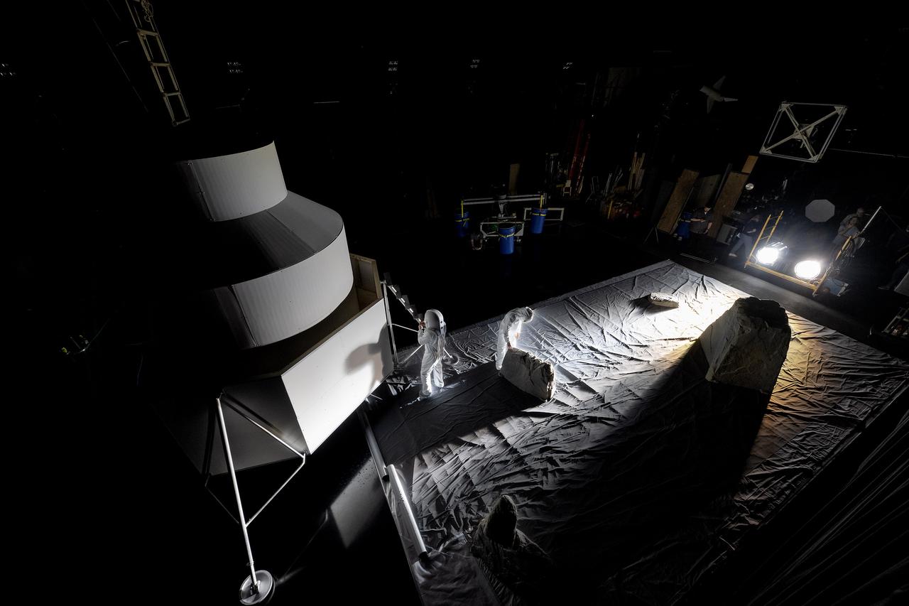
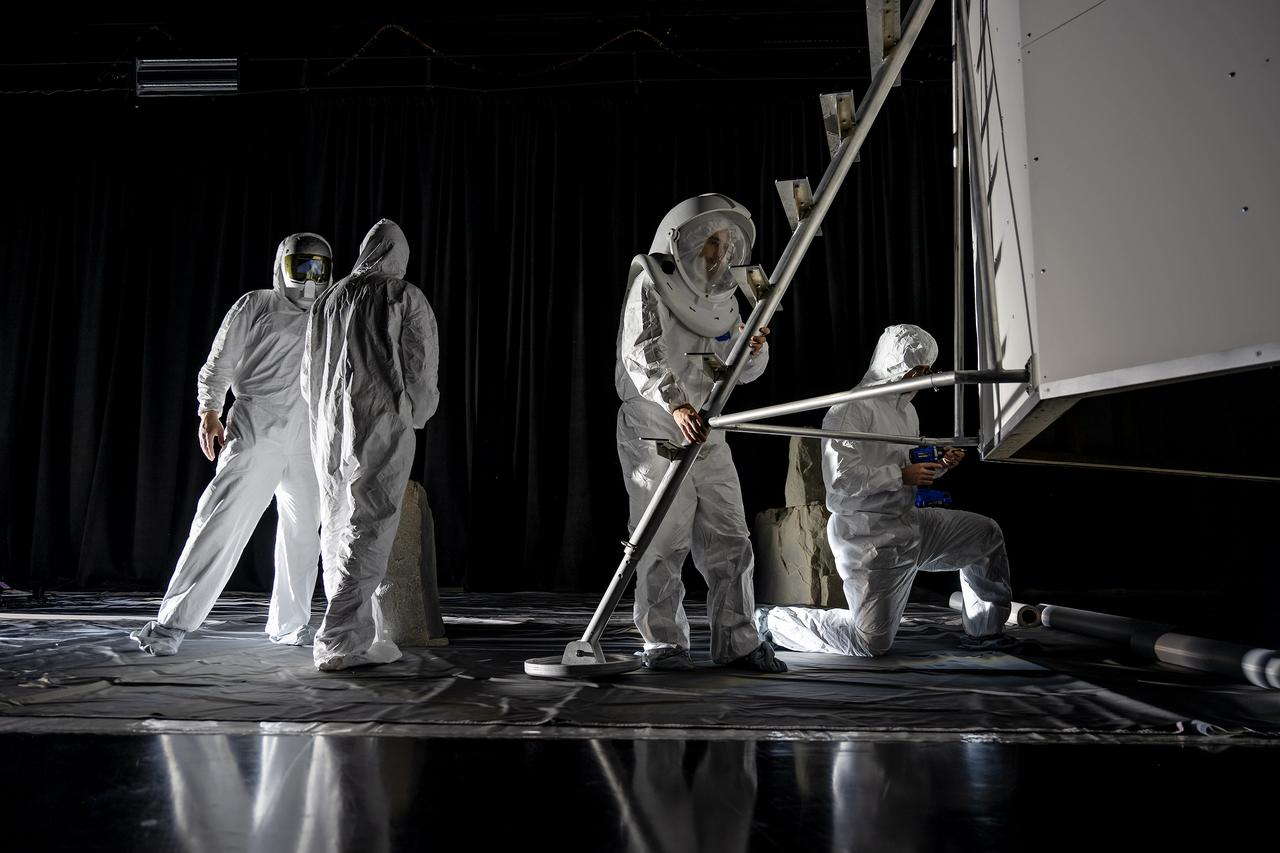
These photos show how teams at NASA’s Marshall Space Flight Center in Huntsville, Alabama, are using the Flat Floor Facility (Building 4619) to understand the lunar lighting environment in preparation for the Artemis III crewed lunar landing mission, slated for 2027. The Flat Floor Facility is an air-bearing floor, providing full-scale simulation capabilities for lunar surface systems by simulating zero gravity in two dimensions. Wearing low-fidelity materials, test engineers can understand how the extreme lighting of the Moon’s South Pole could affect surface operations during Artemis III. High-intensity lights are positioned at a low angle to replicate the strong shadows that are cast across the lunar South Pole by the Sun. Data and analysis from testing at NASA Marshall are improving models Artemis astronauts will use in preparation for lander and surface operations on the Moon during Artemis III. Testing in the facility is also helping cross-agency teams evaluate various tools astronauts may use. NASA Marshall manages the Human Landing System (HLS) Program. For more information, contact NASA Marshall’s Office of Communications at 256-544-0034.
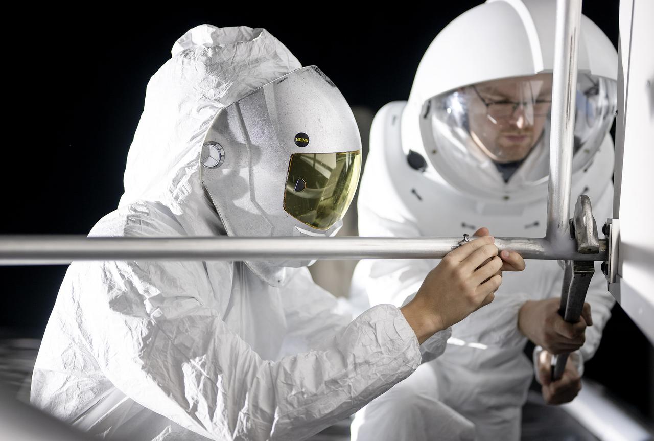
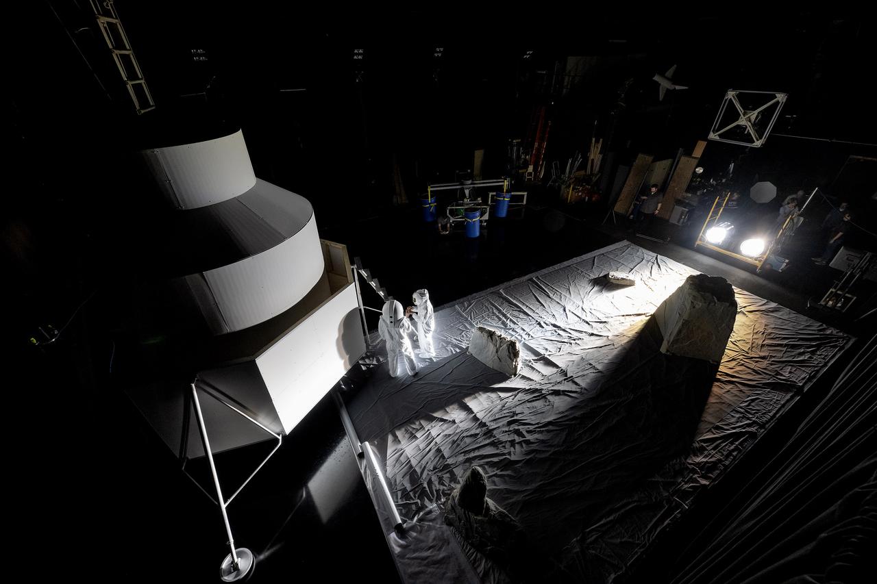
These photos show how teams at NASA’s Marshall Space Flight Center in Huntsville, Alabama, are using the Flat Floor Facility (Building 4619) to understand the lunar lighting environment in preparation for the Artemis III crewed lunar landing mission, slated for 2027. The Flat Floor Facility is an air-bearing floor, providing full-scale simulation capabilities for lunar surface systems by simulating zero gravity in two dimensions. Wearing low-fidelity materials, test engineers can understand how the extreme lighting of the Moon’s South Pole could affect surface operations during Artemis III. High-intensity lights are positioned at a low angle to replicate the strong shadows that are cast across the lunar South Pole by the Sun. Data and analysis from testing at NASA Marshall are improving models Artemis astronauts will use in preparation for lander and surface operations on the Moon during Artemis III. Testing in the facility is also helping cross-agency teams evaluate various tools astronauts may use. NASA Marshall manages the Human Landing System (HLS) Program. For more information, contact NASA Marshall’s Office of Communications at 256-544-0034.
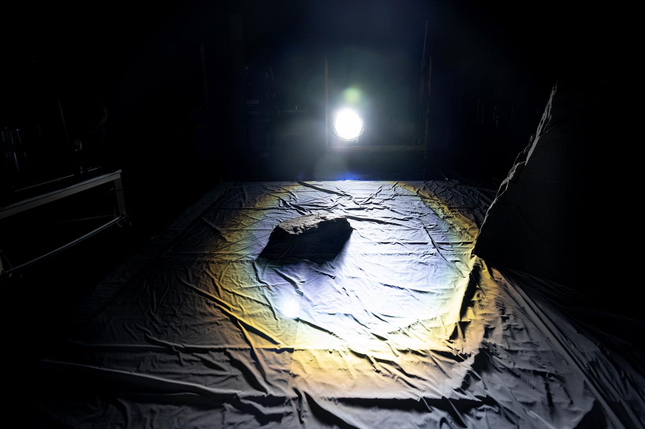
These photos show how teams at NASA’s Marshall Space Flight Center in Huntsville, Alabama, are using the Flat Floor Facility (Building 4619) to understand the lunar lighting environment in preparation for the Artemis III crewed lunar landing mission, slated for 2027. The Flat Floor Facility is an air-bearing floor, providing full-scale simulation capabilities for lunar surface systems by simulating zero gravity in two dimensions. Wearing low-fidelity materials, test engineers can understand how the extreme lighting of the Moon’s South Pole could affect surface operations during Artemis III. High-intensity lights are positioned at a low angle to replicate the strong shadows that are cast across the lunar South Pole by the Sun. Data and analysis from testing at NASA Marshall are improving models Artemis astronauts will use in preparation for lander and surface operations on the Moon during Artemis III. Testing in the facility is also helping cross-agency teams evaluate various tools astronauts may use. NASA Marshall manages the Human Landing System (HLS) Program. For more information, contact NASA Marshall’s Office of Communications at 256-544-0034.
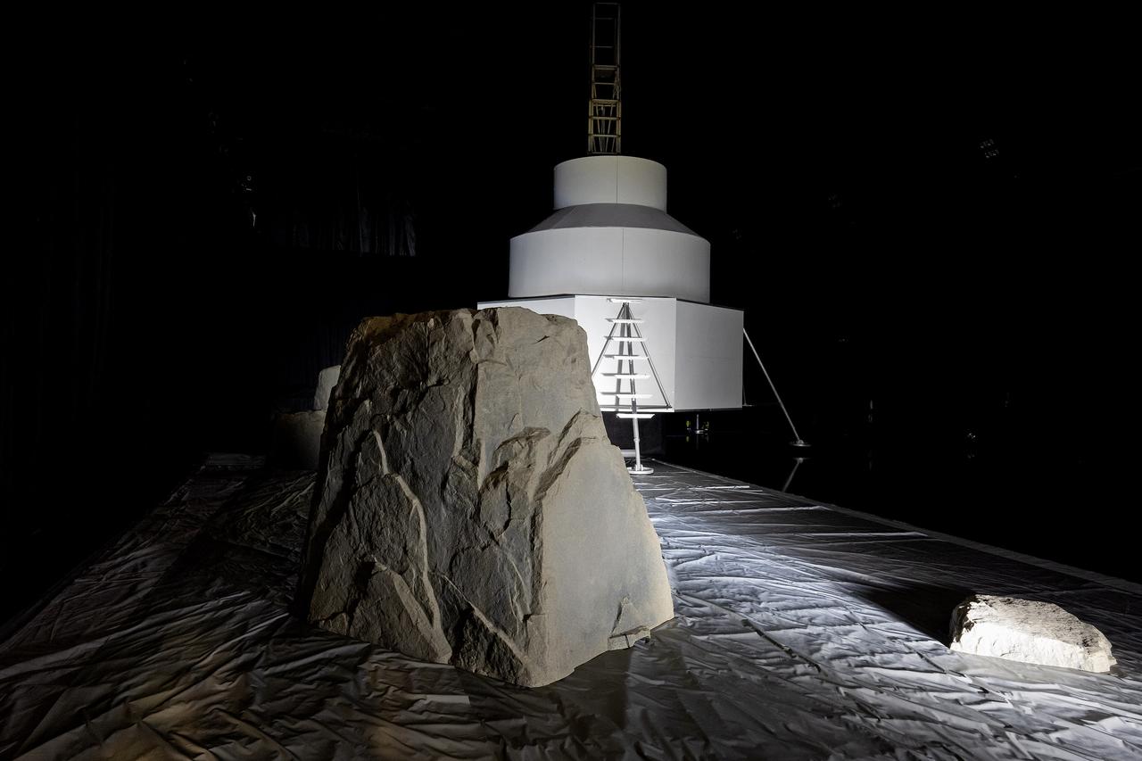
These photos show how teams at NASA’s Marshall Space Flight Center in Huntsville, Alabama, are using the Flat Floor Facility (Building 4619) to understand the lunar lighting environment in preparation for the Artemis III crewed lunar landing mission, slated for 2027. The Flat Floor Facility is an air-bearing floor, providing full-scale simulation capabilities for lunar surface systems by simulating zero gravity in two dimensions. Wearing low-fidelity materials, test engineers can understand how the extreme lighting of the Moon’s South Pole could affect surface operations during Artemis III. High-intensity lights are positioned at a low angle to replicate the strong shadows that are cast across the lunar South Pole by the Sun. Data and analysis from testing at NASA Marshall are improving models Artemis astronauts will use in preparation for lander and surface operations on the Moon during Artemis III. Testing in the facility is also helping cross-agency teams evaluate various tools astronauts may use. NASA Marshall manages the Human Landing System (HLS) Program. For more information, contact NASA Marshall’s Office of Communications at 256-544-0034.

These photos show how teams at NASA’s Marshall Space Flight Center in Huntsville, Alabama, are using the Flat Floor Facility (Building 4619) to understand the lunar lighting environment in preparation for the Artemis III crewed lunar landing mission, slated for 2027. The Flat Floor Facility is an air-bearing floor, providing full-scale simulation capabilities for lunar surface systems by simulating zero gravity in two dimensions. Wearing low-fidelity materials, test engineers can understand how the extreme lighting of the Moon’s South Pole could affect surface operations during Artemis III. High-intensity lights are positioned at a low angle to replicate the strong shadows that are cast across the lunar South Pole by the Sun. Data and analysis from testing at NASA Marshall are improving models Artemis astronauts will use in preparation for lander and surface operations on the Moon during Artemis III. Testing in the facility is also helping cross-agency teams evaluate various tools astronauts may use. NASA Marshall manages the Human Landing System (HLS) Program. For more information, contact NASA Marshall’s Office of Communications at 256-544-0034.
These photos show how teams at NASA’s Marshall Space Flight Center in Huntsville, Alabama, are using the Flat Floor Facility (Building 4619) to understand the lunar lighting environment in preparation for the Artemis III crewed lunar landing mission, slated for 2027. The Flat Floor Facility is an air-bearing floor, providing full-scale simulation capabilities for lunar surface systems by simulating zero gravity in two dimensions. Wearing low-fidelity materials, test engineers can understand how the extreme lighting of the Moon’s South Pole could affect surface operations during Artemis III. High-intensity lights are positioned at a low angle to replicate the strong shadows that are cast across the lunar South Pole by the Sun. Data and analysis from testing at NASA Marshall are improving models Artemis astronauts will use in preparation for lander and surface operations on the Moon during Artemis III. Testing in the facility is also helping cross-agency teams evaluate various tools astronauts may use. NASA Marshall manages the Human Landing System (HLS) Program. For more information, contact NASA Marshall’s Office of Communications at 256-544-0034.
These photos show how teams at NASA’s Marshall Space Flight Center in Huntsville, Alabama, are using the Flat Floor Facility (Building 4619) to understand the lunar lighting environment in preparation for the Artemis III crewed lunar landing mission, slated for 2027. The Flat Floor Facility is an air-bearing floor, providing full-scale simulation capabilities for lunar surface systems by simulating zero gravity in two dimensions. Wearing low-fidelity materials, test engineers can understand how the extreme lighting of the Moon’s South Pole could affect surface operations during Artemis III. High-intensity lights are positioned at a low angle to replicate the strong shadows that are cast across the lunar South Pole by the Sun. Data and analysis from testing at NASA Marshall are improving models Artemis astronauts will use in preparation for lander and surface operations on the Moon during Artemis III. Testing in the facility is also helping cross-agency teams evaluate various tools astronauts may use. NASA Marshall manages the Human Landing System (HLS) Program. For more information, contact NASA Marshall’s Office of Communications at 256-544-0034.
This image shows the central part of the dune field on the floor of Russell Crater. The large ridge "bends" about 60 degrees from parallel to the right side of the image to angle towards the upper left corner. Russell Crater is located in Noachis Terra. A spectacular dune ridge and other dune forms on the crater floor have caused extensive imaging. The Odyssey spacecraft has spent over 15 years in orbit around Mars, circling the planet more than 69000 times. It holds the record for longest working spacecraft at Mars. THEMIS, the IR/VIS camera system, has collected data for the entire mission and provides images covering all seasons and lighting conditions. Over the years many features of interest have received repeated imaging, building up a suite of images covering the entire feature. From the deepest chasma to the tallest volcano, individual dunes inside craters and dune fields that encircle the north pole, channels carved by water and lava, and a variety of other feature, THEMIS has imaged them all. For the next several months the image of the day will focus on the Tharsis volcanoes, the various chasmata of Valles Marineris, and the major dunes fields. We hope you enjoy these images! Orbit Number: 34232 Latitude: -54.4921 Longitude: 12.9013 Instrument: VIS Captured: 2009-09-01 23:04 https://photojournal.jpl.nasa.gov/catalog/PIA21804
CAPE CANAVERAL, Fla. -- In the Payload Hazardous Servicing Facility at Kennedy Space Center in Florida, spacecraft technicians monitor the movement of the robotic arm of the Mars Science Laboratory (MSL) rover, Curiosity, as it is stowed against the body of the spacecraft. The arm will hold and maneuver instruments that will help scientists analyze Martian rocks and soil. Much like a human arm, the robotic arm has flexibility through shoulder, elbow, and wrist joints that permit the arm to extend, bend, and angle precisely against rocks and soil to grind away layers, take microscopic images and analyze their elemental composition. At the end of the arm is a hand-like structure, the turret, for holding various tools that can spin through a 350-degree turning range. A United Launch Alliance Atlas V-541 configuration will be used to loft MSL into space. Curiosity’s 10 science instruments are designed to search for evidence on whether Mars has had environments favorable to microbial life, including chemical ingredients for life. The unique rover will use a laser to look inside rocks and release its gasses so that the rover’s spectrometer can analyze and send the data back to Earth. MSL is scheduled to launch Nov. 25 from Space Launch Complex 41 on Cape Canaveral Air Force Station in Florida. For more information, visit http://www.nasa.gov/msl. Photo credit: NASA/Charisse Nahser
CAPE CANAVERAL, Fla. -- In the Payload Hazardous Servicing Facility at NASA's Kennedy Space Center in Florida, preparations are under way to stow the robotic arm on the Mars Science Laboratory (MSL) rover, Curiosity. The arm will hold and maneuver instruments that will help scientists analyze Martian rocks and soil. Much like a human arm, the robotic arm has flexibility through shoulder, elbow, and wrist joints that permit the arm to extend, bend, and angle precisely against rocks and soil to grind away layers, take microscopic images and analyze their elemental composition. At the end of the arm is a hand-like structure, the turret, for holding various tools that can spin through a 350-degree turning range. A United Launch Alliance Atlas V-541 configuration will be used to loft MSL into space. Curiosity’s 10 science instruments are designed to search for evidence on whether Mars has had environments favorable to microbial life, including chemical ingredients for life. The unique rover will use a laser to look inside rocks and release its gasses so that the rover’s spectrometer can analyze and send the data back to Earth. MSL is scheduled to launch Nov. 25 from Space Launch Complex 41 on Cape Canaveral Air Force Station in Florida. For more information, visit http://www.nasa.gov/msl. Photo credit: NASA/Charisse Nahser
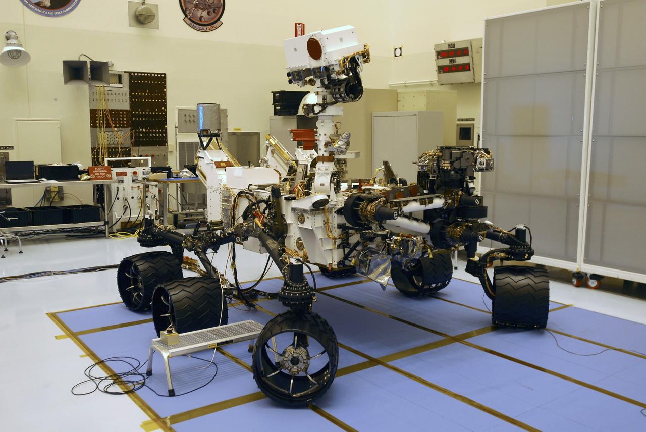
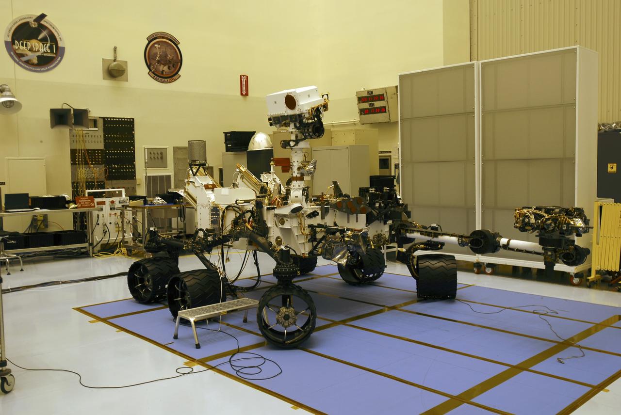
CAPE CANAVERAL, Fla. -- In the Payload Hazardous Servicing Facility at NASA's Kennedy Space Center in Florida, the robotic arm of the Mars Science Laboratory (MSL) rover, Curiosity, has been stowed against the body of the spacecraft. The arm will hold and maneuver instruments that will help scientists analyze Martian rocks and soil. Much like a human arm, the robotic arm has flexibility through shoulder, elbow, and wrist joints that permit the arm to extend, bend, and angle precisely against rocks and soil to grind away layers, take microscopic images and analyze their elemental composition. At the end of the arm is a hand-like structure, the turret, for holding various tools that can spin through a 350-degree turning range. A United Launch Alliance Atlas V-541 configuration will be used to loft MSL into space. Curiosity’s 10 science instruments are designed to search for evidence on whether Mars has had environments favorable to microbial life, including chemical ingredients for life. The unique rover will use a laser to look inside rocks and release its gasses so that the rover’s spectrometer can analyze and send the data back to Earth. MSL is scheduled to launch Nov. 25 from Space Launch Complex 41 on Cape Canaveral Air Force Station in Florida. For more information, visit http://www.nasa.gov/msl. Photo credit: NASA/Charisse Nahser
CAPE CANAVERAL, Fla. -- In the Payload Hazardous Servicing Facility at NASA's Kennedy Space Center in Florida, spacecraft technicians prepare to stow the robotic arm on the Mars Science Laboratory (MSL) rover, Curiosity. The arm will hold and maneuver instruments that will help scientists analyze Martian rocks and soil. Much like a human arm, the robotic arm has flexibility through shoulder, elbow, and wrist joints that permit the arm to extend, bend, and angle precisely against rocks and soil to grind away layers, take microscopic images and analyze their elemental composition. At the end of the arm is a hand-like structure, the turret, for holding various tools that can spin through a 350-degree turning range. A United Launch Alliance Atlas V-541 configuration will be used to loft MSL into space. Curiosity’s 10 science instruments are designed to search for evidence on whether Mars has had environments favorable to microbial life, including chemical ingredients for life. The unique rover will use a laser to look inside rocks and release its gasses so that the rover’s spectrometer can analyze and send the data back to Earth. MSL is scheduled to launch Nov. 25 from Space Launch Complex 41 on Cape Canaveral Air Force Station in Florida. For more information, visit http://www.nasa.gov/msl. Photo credit: NASA/Charisse Nahser
JOHNSON SPACE CENTER, HOUSON, TEXAS -- STS-107 INSIGNIA -- This is the insignia for STS-107, which is a multi-discipline microgravity and Earth science research mission with a multitude of international scientific investigations conducted continuously during the planned 16 days on orbit. The central element of the patch is the microgravity symbol flowing into the rays of the astronaut symbol. The mission inclination is portrayed by the 39-degree angle of the astronaut symbol to the Earth's horizon. The sunrise is representative of the numerous experiments that are the dawn of a new era for continued microgravity research on the International Space Station and beyond. The breadth of science conducted on this mission will have widespread benefits to life on Earth and our continued exploration of space, illustrated by the Earth and stars. The constellation Columba (the dove) was chosen to symbolize peace on Earth and the Space Shuttle Columbia. The seven stars also represent the mission crew members and honor the original astronauts who paved the way to make research in space possible. The Israeli flag is adjacent to the name of the payload specialist who is the first person from that country to fly on the Space Shuttle. The NASA insignia design for Space Shuttle flights is reserved for use by the astronauts and for other official use as the NASA Administrator may authorize. Public availability has been approved only in the form of illustrations by the various news media. When and if there is any change in this policy, which we do not anticipate, it will be publicly announced.

CAPE CANAVERAL, Fla. -- In the Payload Hazardous Servicing Facility at NASA's Kennedy Space Center in Florida, spacecraft technicians discuss their readiness to stow the robotic arm on the Mars Science Laboratory (MSL) rover, Curiosity. The arm will hold and maneuver instruments that will help scientists analyze Martian rocks and soil. Much like a human arm, the robotic arm has flexibility through shoulder, elbow, and wrist joints that permit the arm to extend, bend, and angle precisely against rocks and soil to grind away layers, take microscopic images and analyze their elemental composition. At the end of the arm is a hand-like structure, the turret, for holding various tools that can spin through a 350-degree turning range. A United Launch Alliance Atlas V-541 configuration will be used to loft MSL into space. Curiosity’s 10 science instruments are designed to search for evidence on whether Mars has had environments favorable to microbial life, including chemical ingredients for life. The unique rover will use a laser to look inside rocks and release its gasses so that the rover’s spectrometer can analyze and send the data back to Earth. MSL is scheduled to launch Nov. 25 from Space Launch Complex 41 on Cape Canaveral Air Force Station in Florida. For more information, visit http://www.nasa.gov/msl. Photo credit: NASA/Charisse Nahser
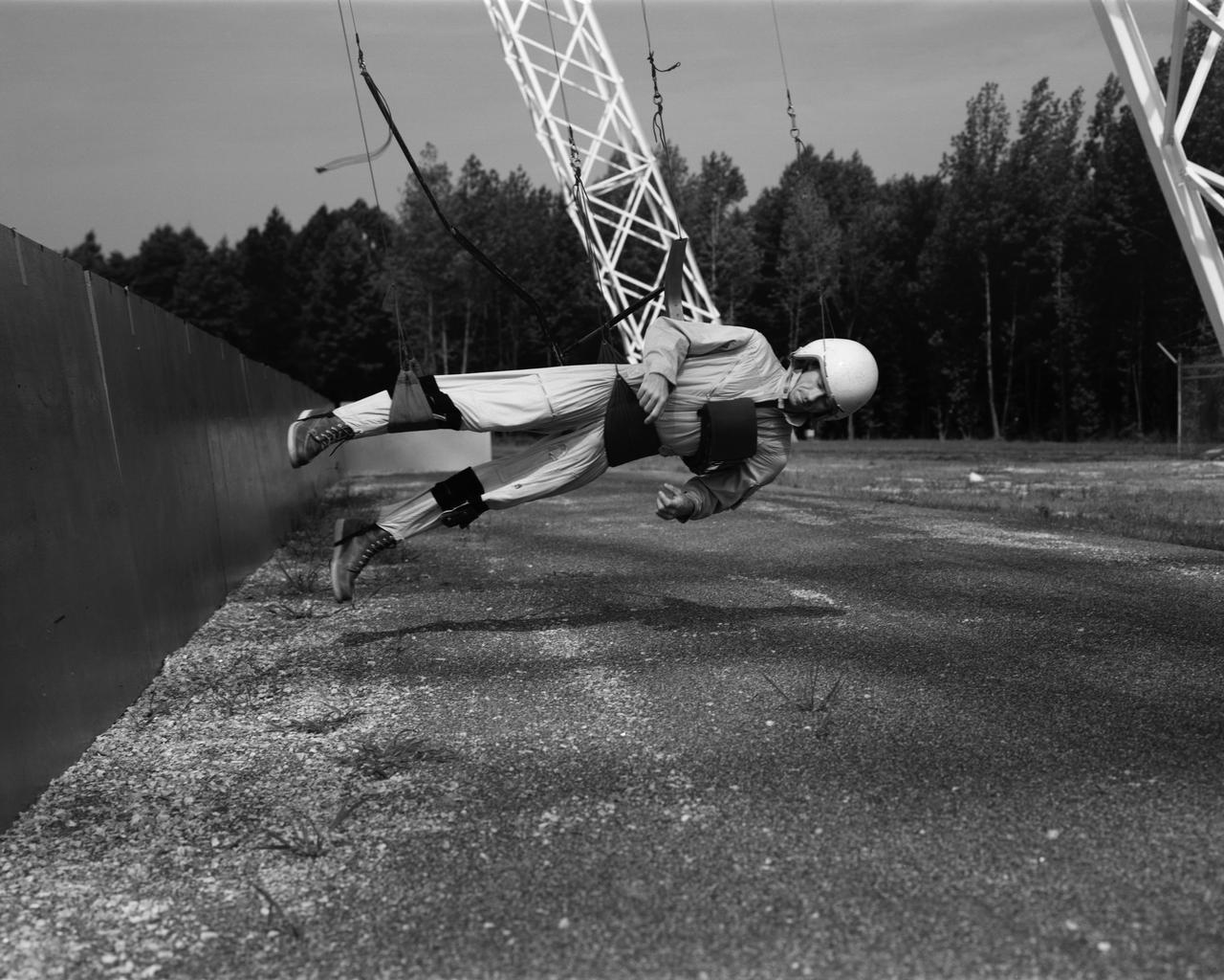
Reduced Gravity Walking Simulator located in the hangar at Langley Research Center. The initial version of this simulator was located inside the hangar. Later a larger version would be located at the Lunar Landing Facility. The purpose of this simulator was to study the subject while walking, jumping or running. Researchers conducted studies of various factors such as fatigue limit, energy expenditure, and speed of locomotion. A.W. Vigil wrote in his paper Discussion of Existing and Planned Simulators for Space Research, When the astronauts land on the moon they will be in an unfamiliar environment involving, particularly, a gravitational field only one-sixth as strong as on earth. A novel method of simulating lunar gravity has been developed and is supported by a puppet-type suspension system at the end of a long pendulum. A floor is provided at the proper angle so that one-sixth of the subject' s weight is supported by the floor with the remainder being supported by the suspension system. This simulator allows almost complete freedom in vertical translation and pitch and is considered to be a very realistic simulation of the lunar walking problem. For this problem this simulator suffers only slightly from the restrictions in lateral movement it puts on the test subject. This is not considered a strong disadvantage for ordinary walking problems since most of the motions do, in fact, occur in the vertical plane. However, this simulation technique would be severely restrictive if applied to the study of the extra-vehicular locomotion problem, for example, because in this situation complete six degrees of freedom are rather necessary. This technique, in effect, automatically introduces a two-axis attitude stabilization system into the problem. The technique could, however, be used in preliminary studies of extra-vehicular locomotion where, for example, it might be assumed that one axis of the attitude control system on the astronaut maneuvering unit may have failed. -- Published in James R. Hansen, Spaceflight Revolution: NASA Langley Research Center From Sputnik to Apollo, NASA SP-4308, p. 377 A.W. Vigil, Discussion of Existing and Planned Simulators for Space Research, Paper presented at Conference on the Role of Simulation in Space Technology, Blacksburg, VA, August 17-21, 1964.
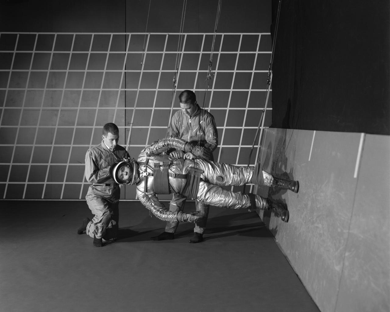
A test subject being suited up for studies on the Reduced Gravity Walking Simulator located in the hangar at Langley Research Center. The initial version of this simulator was located inside the hangar. Later a larger version would be located at the Lunar Landing Facility. The purpose of this simulator was to study the subject while walking, jumping or running. Researchers conducted studies of various factors such as fatigue limit, energy expenditure, and speed of locomotion. Francis B. Smith wrote in his paper "Simulators For Manned Space Research," "I would like to conclude this talk with a discussion of a device for simulating lunar gravity which is very effective and yet which is so simple that its cost is in the order of a few thousand dollars at most, rather than hundreds of thousands. With a little ingenuity, one could almost build this type simulator in his backyard for children to play on. The principle is ...if a test subject is suspended in a sling so that his body axis makes an angle of 9 1/2 degrees with the horizontal and if he then "stands" on a platform perpendicular to his body axis, the component of the earth's gravity forcing him toward the platform is one times the sine of 9 1/2 degrees or approximately 1/6 of the earth's normal gravity field. That is, a 180 pound astronaut "standing" on the platform would exert a force of only 30 pounds - the same as if he were standing upright on the lunar surface." -- Published in James R. Hansen, Spaceflight Revolution: NASA Langley Research Center From Sputnik to Apollo, NASA SP-4308; Francis B. Smith, "Simulators For Manned Space Research," Paper for 1966 IEEE International Convention, New York, NY, March 21-25, 1966

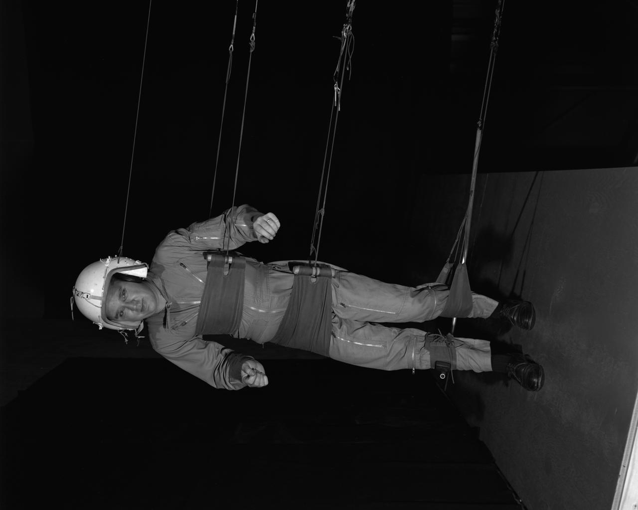
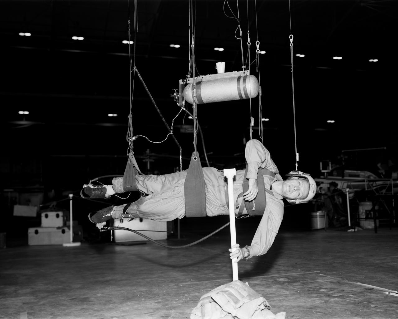
Astronaut Roger Chaffee on the Reduced Gravity Walking Simulator located at the Lunar Landing Facility. The purpose of this simulator was to study the subject while walking, jumping or running. Researchers conducted studies of various factors such as fatigue limit, energy expenditure, and speed of locomotion. A.W. Vigil, described the simulator as follows: "When the astronauts land on the moon they will be in an unfamiliar environment involving, particularly, a gravitational field only one-sixth as strong as on earth. A novel method of simulating lunar gravity has been developed and is supported by a puppet-type suspension system at the end of a long pendulum. A floor is provided at the proper angle so that one-sixth of the subject's weight is supported by the floor with the remainder being supported by the suspension system. This simulator allows almost complete freedom in vertical translation and pitch and is considered to be a very realistic simulation of the lunar walking problem. For this problem this simulator suffers only slightly from the restrictions in lateral movement it puts on the test subject. This is not considered a strong disadvantage for ordinary walking problems since most of the motions do, in fact, occur in the vertical plane. However, this simulation technique would be severely restrictive if applied to the study of the extra-vehicular locomotion problem, for example, because in this situation complete six degrees of freedom are rather necessary. This technique, in effect, automatically introduces a two-axis attitude stabilization system into the problem. The technique could, however, be used in preliminary studies of extra-vehicular locomotion where, for example, it might be assumed that one axis of the attitude control system on the astronaut maneuvering unit may have failed." -- Published in James R. Hansen, Spaceflight Revolution: NASA Langley Research Center From Sputnik to Apollo, NASA SP-4308, p. 377; A.W. Vigil, "Discussion of Existing and Planned Simulators for Space Research," Paper presented at Conference on the Role of Simulation in Space Technology," Blacksburg, VA, August 17-21, 1964.
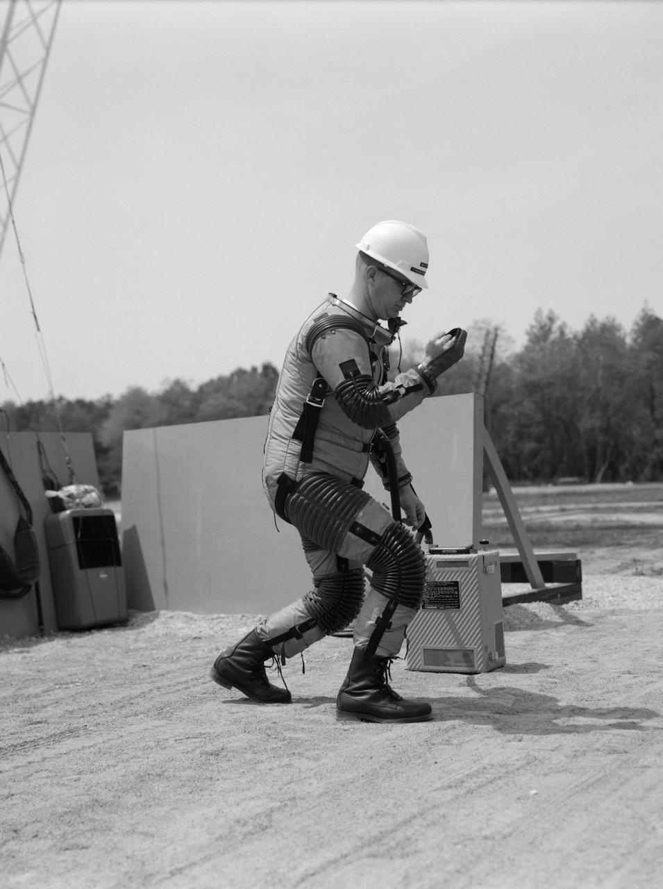
Special "space" suit for the Reduced Gravity Walking Simulator located at the Lunar Landing Facility. The purpose of this simulator was to study the subject while walking, jumping or running. Researchers conducted studies of various factors such as fatigue limit, energy expenditure, and speed of locomotion. A.W. Vigil described the purpose of the simulator in his paper "Discussion of Existing and Planned Simulators for Space Research," "When the astronauts land on the moon they will be in an unfamiliar environment involving, particularly, a gravitational field only one-sixth as strong as on earth. A novel method of simulating lunar gravity has been developed and is supported by a puppet-type suspension system at the end of a long pendulum. A floor is provided at the proper angle so that one-sixth of the subject's weight is supported by the floor with the remainder being supported by the suspension system. This simulator allows almost complete freedom in vertical translation and pitch and is considered to be a very realistic simulation of the lunar walking problem. For this problem this simulator suffers only slightly from the restrictions in lateral movement it puts on the test subject. This is not considered a strong disadvantage for ordinary walking problems since most of the motions do, in fact, occur in the vertical plane. However, this simulation technique would be severely restrictive if applied to the study of the extra-vehicular locomotion problem, for example, because in this situation complete six degrees of freedom are rather necessary. This technique, in effect, automatically introduces a two-axis attitude stabilization system into the problem. The technique could, however, be used in preliminary studies of extra-vehicular locomotion where, for example, it might be assumed that one axis of the attitude control system on the astronaut maneuvering unit may have failed." -- Published in James R. Hansen, Spaceflight Revolution: NASA Langley Research Center From Sputnik to Apollo, (Washington: NASA, 1995), p. 377; A.W. Vigil, "Discussion of Existing and Planned Simulators for Space Research," Paper presented at Conference on the Role of Simulation in Space Technology," Blacksburg, VA, August 17-21, 1964.
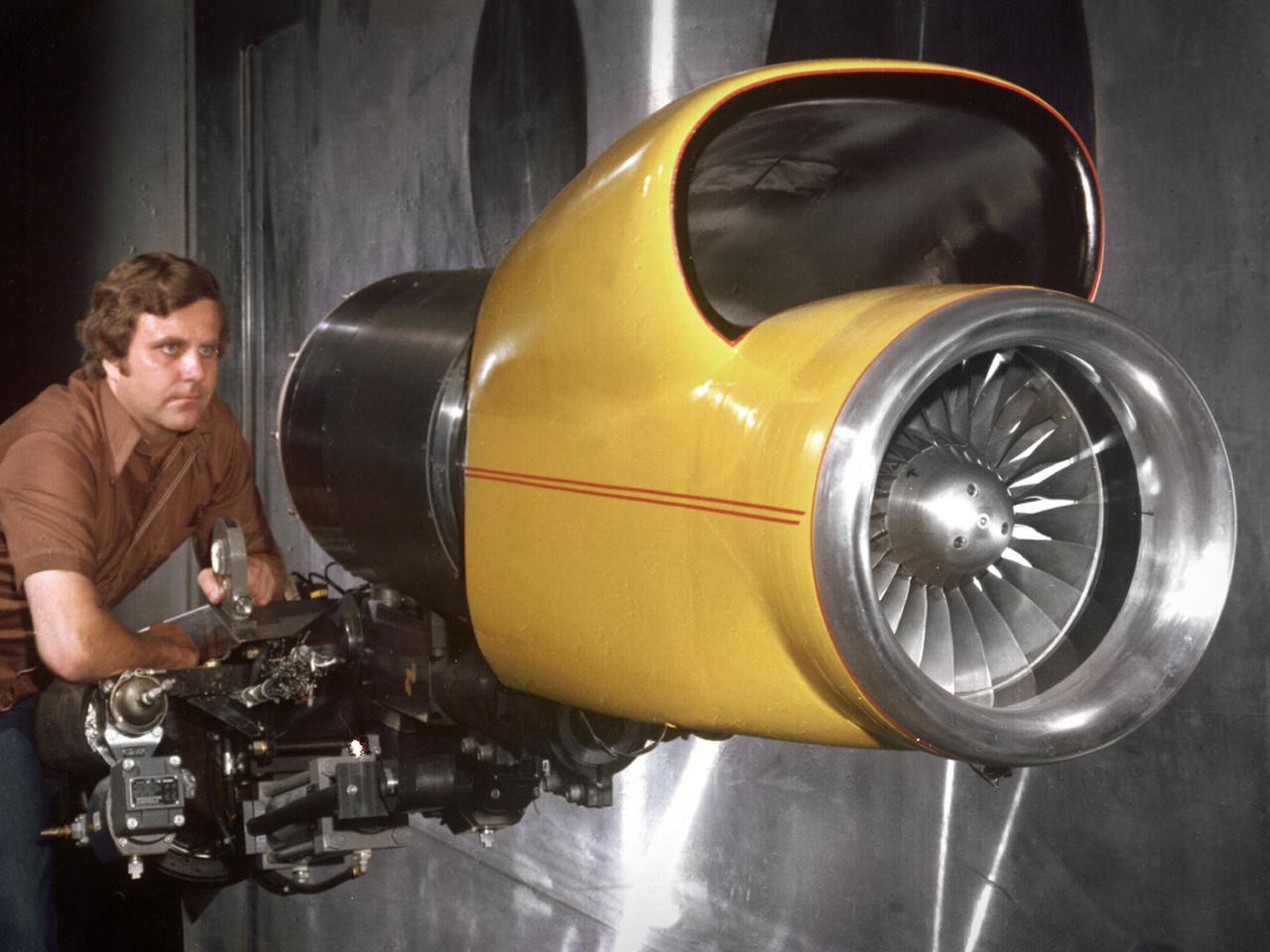
A technician checks a 0.25-scale engine model of a Vought Corporation V-530 engine in the test section of the 10- by 10-Foot Supersonic Wind Tunnel at the National Aeronautics and Space Administration (NASA) Lewis Research Center. Vought created a low-drag tandem-fan Vertical/Short and Takeoff and Landing (V/STOL) engine in the mid-1970s, designated as the V-530. The first fan on the tandem-fan engine was supplied with air through a traditional subsonic inlet, seen on the lower front of the engine. The air was exhausted through the nacelle during normal flight and directed down during takeoffs. The rear fan was supplied by the oval-shaped top inlet during all phases of the flight. The second fan exhausted its air through a rear vectorable nozzle. NASA Lewis and Vought partnered in the late 1970s to collect an array of inlet and nozzle design information on the tandem fan engines for the Navy. Vought created this .25-scale model of the V-530 for extensive testing in Lewis' 10- by 10-foot tunnel. During an early series of tests, the front fan was covered, and a turbofan simulator was used to supply air to the rear fan. The researchers then analyzed the performance of only the front fan inlet. During the final series of tests, the flow from the front fan was used to supply airflow to the rear fan. The researchers studied the inlet's recovery, distortion, and angle-of-attack limits over various flight conditions.
Astronaut Walt Cunningham on the Reduced Gravity Walking Simulator located at the Lunar Landing Facility. The purpose of this simulator was to study the subject while walking, jumping or running. Researchers conducted studies of various factors such as fatigue limit, energy expenditure, and speed of locomotion. A.W. Vigil described the purpose of the simulator in his paper "Discussion of Existing and Planned Simulators for Space Research," "When the astronauts land on the moon they will be in an unfamiliar environment involving, particularly, a gravitational field only one-sixth as strong as on earth. A novel method of simulating lunar gravity has been developed and is supported by a puppet-type suspension system at the end of a long pendulum. A floor is provided at the proper angle so that one-sixth of the subject's weight is supported by the floor with the remainder being supported by the suspension system. This simulator allows almost complete freedom in vertical translation and pitch and is considered to be a very realistic simulation of the lunar walking problem. For this problem this simulator suffers only slightly from the restrictions in lateral movement it puts on the test subject. This is not considered a strong disadvantage for ordinary walking problems since most of the motions do, in fact, occur in the vertical plane. However, this simulation technique would be severely restrictive if applied to the study of the extra-vehicular locomotion problem, for example, because in this situation complete six degrees of freedom are rather necessary. This technique, in effect, automatically introduces a two-axis attitude stabilization system into the problem. The technique could, however, be used in preliminary studies of extra-vehicular locomotion where, for example, it might be assumed that one axis of the attitude control system on the astronaut maneuvering unit may have failed." -- Published in James R. Hansen, Spaceflight Revolution: NASA Langley Research Center From Sputnik to Apollo, (Washington: NASA, 1995), p. 377; A.W. Vigil, "Discussion of Existing and Planned Simulators for Space Research," Paper presented at Conference on the Role of Simulation in Space Technology," Blacksburg, VA, August 17-21, 1964.
Cable system which supports the test subject on the Reduced Gravity Walking Simulator. The purpose of this simulator was to study the subject while walking, jumping or running. Researchers conducted studies of various factors such as fatigue limit, energy expenditure, and speed of locomotion. A.W. Vigil described the purpose of the simulator as follows: "When the astronauts land on the moon they will be in an unfamiliar environment involving, particularly, a gravitational field only one-sixth as strong as on earth. A novel method of simulating lunar gravity has been developed and is supported by a puppet-type suspension system at the end of a long pendulum. A floor is provided at the proper angle so that one-sixth of the subject's weight is supported by the floor with the remainder being supported by the suspension system. This simulator allows almost complete freedom in vertical translation and pitch and is considered to be a very realistic simulation of the lunar walking problem. For this problem this simulator suffers only slightly from the restrictions in lateral movement it puts on the test subject. This is not considered a strong disadvantage for ordinary walking problems since most of the motions do, in fact, occur in the vertical plane. However, this simulation technique would be severely restrictive if applied to the study of the extra-vehicular locomotion problem, for example, because in this situation complete six degrees of freedom are rather necessary. This technique, in effect, automatically introduces a two-axis attitude stabilization system into the problem. The technique could, however, be used in preliminary studies of extra-vehicular locomotion where, for example, it might be assumed that one axis of the attitude control system on the astronaut maneuvering unit may have failed." -- Published in James R. Hansen, Spaceflight Revolution: NASA Langley Research Center From Sputnik to Apollo, (Washington: NASA, 1995); A.W. Vigil, "Discussion of Existing and Planned Simulators for Space Research," Paper presented at Conference on the Role of Simulation in Space Technology," Blacksburg, VA, August 17-21, 1964.
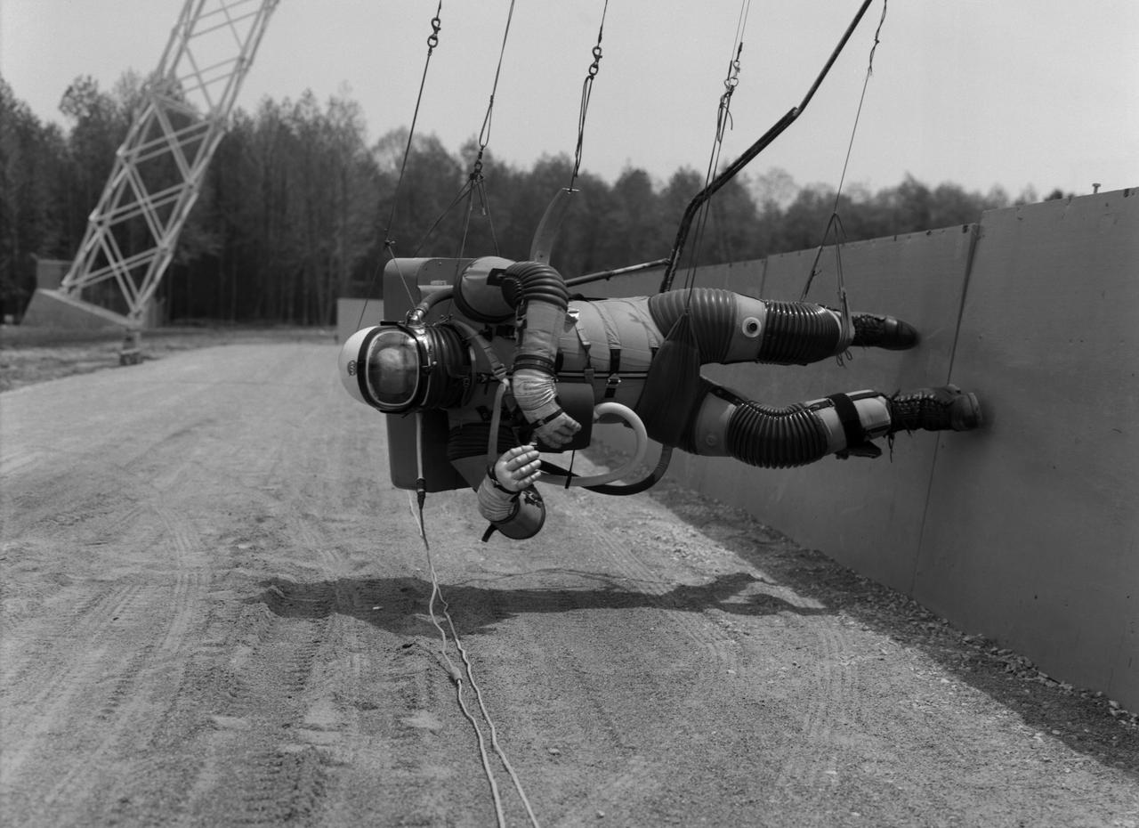
Test subject wearing the pressurized "space" suit for the Reduced Gravity Walking Simulator located at the Lunar Landing Facility. The purpose of this simulator was to study the subject while walking, jumping or running. Researchers conducted studies of various factors such as fatigue limit, energy expenditure, and speed of locomotion. A.W. Vigil described the purpose of the simulator in his paper "Discussion of Existing and Planned Simulators for Space Research," "When the astronauts land on the moon they will be in an unfamiliar environment involving, particularly, a gravitational field only one-sixth as strong as on earth. A novel method of simulating lunar gravity has been developed and is supported by a puppet-type suspension system at the end of a long pendulum. A floor is provided at the proper angle so that one-sixth of the subject's weight is supported by the floor with the remainder being supported by the suspension system. This simulator allows almost complete freedom in vertical translation and pitch and is considered to be a very realistic simulation of the lunar walking problem. For this problem this simulator suffers only slightly from the restrictions in lateral movement it puts on the test subject. This is not considered a strong disadvantage for ordinary walking problems since most of the motions do, in fact, occur in the vertical plane. However, this simulation technique would be severely restrictive if applied to the study of the extra-vehicular locomotion problem, for example, because in this situation complete six degrees of freedom are rather necessary. This technique, in effect, automatically introduces a two-axis attitude stabilization system into the problem. The technique could, however, be used in preliminary studies of extra-vehicular locomotion where, for example, it might be assumed that one axis of the attitude control system on the astronaut maneuvering unit may have failed." -- Published in James R. Hansen, Spaceflight Revolution: NASA Langley Research Center From Sputnik to Apollo, (Washington: NASA, 1995), p. 377; A.W. Vigil, "Discussion of Existing and Planned Simulators for Space Research," Paper presented at Conference on the Role of Simulation in Space Technology," Blacksburg, VA, August 17-21, 1964.
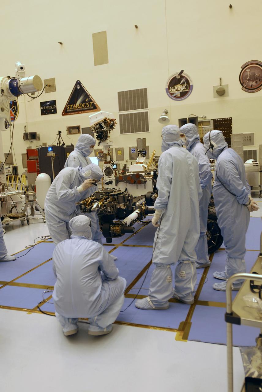
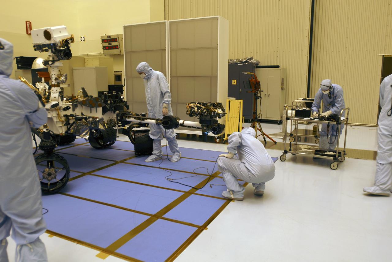
CAPE CANAVERAL, Fla. -- In the Payload Hazardous Servicing Facility at NASA's Kennedy Space Center in Florida, spacecraft technicians examine the Mars Science Laboratory (MSL) rover, Curiosity, to ensure that the proper steps have been taken to stow the spacecraft's robotic arm. The arm will hold and maneuver instruments that will help scientists analyze Martian rocks and soil. Much like a human arm, the robotic arm has flexibility through shoulder, elbow, and wrist joints that permit the arm to extend, bend, and angle precisely against rocks and soil to grind away layers, take microscopic images and analyze their elemental composition. At the end of the arm is a hand-like structure, the turret, for holding various tools that can spin through a 350-degree turning range. A United Launch Alliance Atlas V-541 configuration will be used to loft MSL into space. Curiosity’s 10 science instruments are designed to search for evidence on whether Mars has had environments favorable to microbial life, including chemical ingredients for life. The unique rover will use a laser to look inside rocks and release its gasses so that the rover’s spectrometer can analyze and send the data back to Earth. MSL is scheduled to launch Nov. 25 from Space Launch Complex 41 on Cape Canaveral Air Force Station in Florida. For more information, visit http://www.nasa.gov/msl. Photo credit: NASA/Charisse Nahser
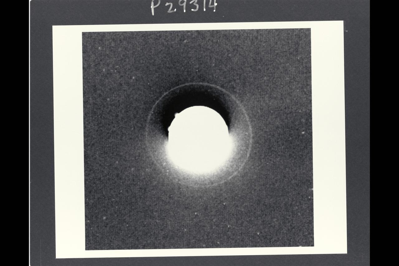
Range: 72.3 million km. ( 44.9 million miles ) P-29314B/W This Voyager 2 photograph of Uranus shows the planets outermost, or epsilon, ring. This is a computerized summation of six images shot by the narrow angle camera. It is the first photo to show the epsilon ring unblurred by Earth's atmosphere. The Epsilon ring, some 51,200 km. ( 31,800 miles ) from the planets center, is the most prominent of Uranus' nine known rings. Ground based observations of stellar occulations by the rings have determined that the Epsilon ring is eccentric, or elliptical, with its widest portion about 100 km. ( 60 miles ) wide and its narrowest portion about 20 km. (12 miles ). Estimates of the rings brightness suggest that it is also very dark, with a reflectance of only 1 or 2 percent and a probable composition of carbonaceous material similiar to that on dark asteroids and the dark side of Saturn's moon Lapetus. Because the ring is so narrow and dark, at this range, the Voyager camera could not resolve even the widest part, resulting in long exposure times so obtain a good image. six exposures of 11 or 15 second duration were added together by computer to produce this image. In this image, the central portion is greatly overexposed. Various artifacts due to electronic effects and image proccessing can be seen in the central portion of the frame, including the dark image just above the planets image, the diffuse brightening below it and the small, bright projection from the edge of the planet in the upper left. The ring is distinctly less prominent in the lower left portion and more prominent in the upper right. This is in agreement with the predicted locations of the narrow and wide portions of the ring, respectively.
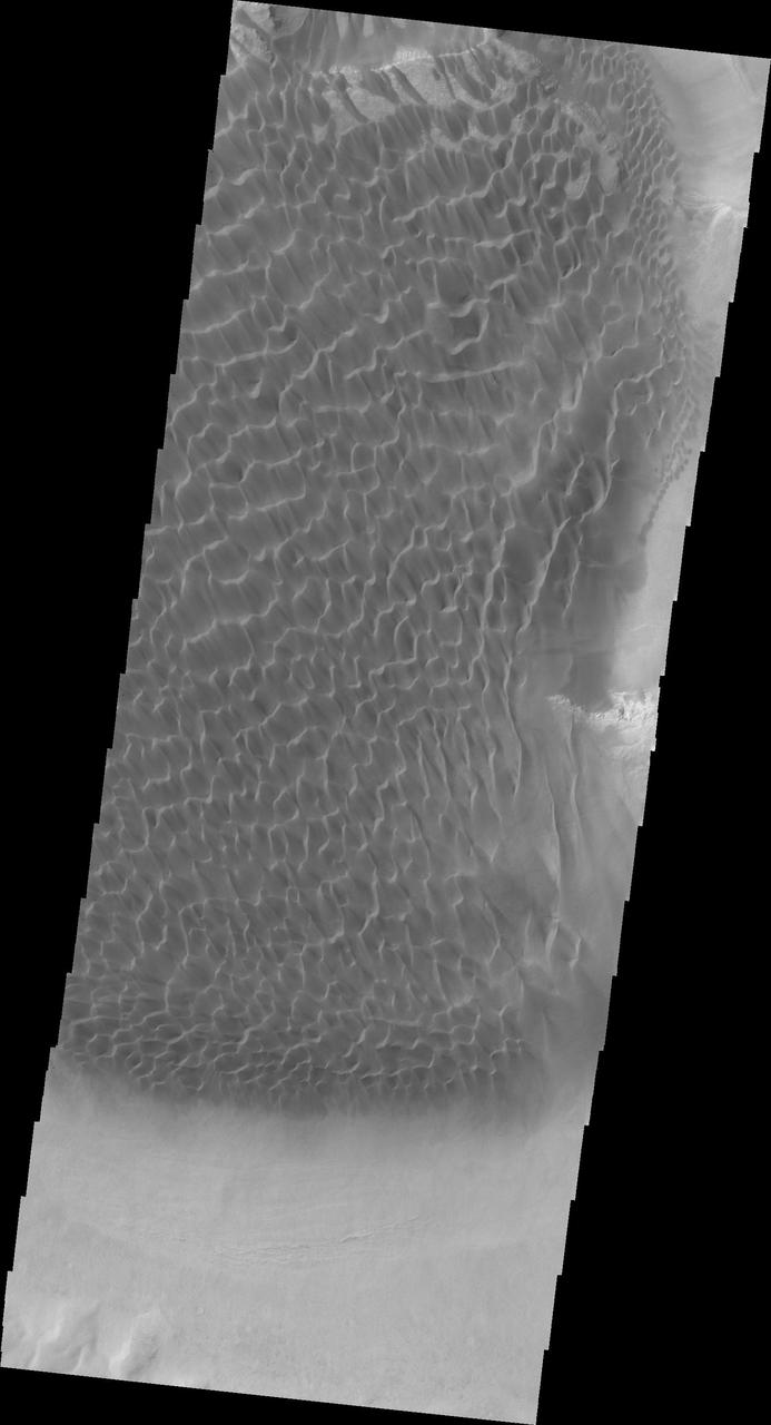
Kaiser Crater is located in the southern hemisphere in the Noachis region west of Hellas Planitia. Kaiser Crater is just one of several large craters with extensive dune fields on the crater floor. Other nearby dune filled craters are Proctor, Russell, and Rabe. Kaiser Crater is 207 km (129 miles) in diameter. The dunes are located in the southeastern part of the crater floor. Most of the individual dunes in Kaiser Crater are barchan dunes. Barchan dunes are crescent shaped with the points of the crescent pointing downwind. The sand is blown up the low angle side of the dune and then tumbles down the steep slip face. This dune type forms on hard surfaces where there is limited amounts of sand. Barchan dunes can merge together over time with increased sand in the local area. The Odyssey spacecraft has spent over 15 years in orbit around Mars, circling the planet more than 69000 times. It holds the record for longest working spacecraft at Mars. THEMIS, the IR/VIS camera system, has collected data for the entire mission and provides images covering all seasons and lighting conditions. Over the years many features of interest have received repeated imaging, building up a suite of images covering the entire feature. From the deepest chasma to the tallest volcano, individual dunes inside craters and dune fields that encircle the north pole, channels carved by water and lava, and a variety of other feature, THEMIS has imaged them all. For the next several months the image of the day will focus on the Tharsis volcanoes, the various chasmata of Valles Marineris, and the major dunes fields. We hope you enjoy these images! Orbit Number: 1036 Latitude: -46.7795 Longitude: 20.2075 Instrument: VIS Captured: 2002-03-09 20:07 https://photojournal.jpl.nasa.gov/catalog/PIA22172
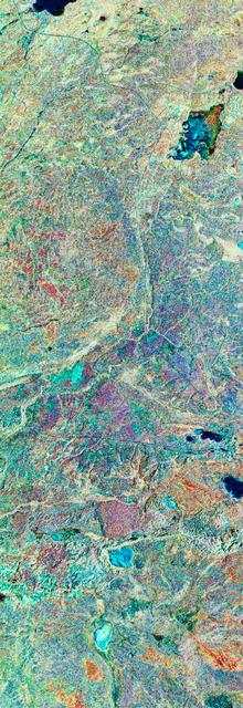
STS059-S-079 (18 April 1994) --- This is a false-color, three frequency image of Prince Albert, Canada, centered at 53.91 north latitude and 104.69 west longitude. It was produced using data from the X-Band, C-Band and L-Band radars that comprise the Spaceborne Imaging Radar-C and X-Band Synthetic Aperture Radar (SIR-C/X-SAR). SIR-C/X-SAR acquired this image on the 20th orbit of the Space Shuttle Endeavour. The area is located 40 kilometers north and 30 kilometers east of the town of Prince Albert in the Saskatchewan province of Canada. The image covers the area east of the Candle Lake, between gravel surface Highways 120 and 106 and west of 106. The area in the middle of the image covers the entire Nipawin (Narrow Hills) provincial park. The look angle of the radar is 30 degrees and the size of the image is approximately 20 by 50 kilometers. The red, green, and blue colors represent L-Band total power, C-Band total power, and XVV respectively. The changes in the intensity of each color are related to various surface conditions such as frozen or thawed forest, fire, deforestation and areas of regrowth. Most of the dark blue areas in the image are the ice covered lakes. The dark area on the top right corner of the image is the White Gull Lake north of the intersection of Highway 120 and 913. The right middle part of the image shows Lake Ispuchaw and Lower Fishing Lake. The deforested areas are shown by light blue in the image. Since most of the logging practice at the Prince Albert area is around the major highways, the deforested areas can be easily detected as small geometrically shaped dark regions along the roads. At the time these data were taken, a major part of the forest was either frozen or undergoing the spring thaw. In such conditions, due to low volume of water in the vegetation, a deeper layer of the canopy is imaged by the radar, revealing valuable information about the type of trees, the amount of vegetation biomass and the condition of the surface. As the frequency increases, the penetration depth in the canopy decreases. Over forest canopies, the X-Band radar contains information about the top of the canopy. Whereas, C-Band and L-Band radar returns show contributions from the crown and trunk areas respectively. The bright areas in the image are dense mixed aspen and old jackpine forests where the return from all three bands is high. The reddish area corresponds to more sparse old jack pine (12 to 17 meters in height and 60 to 75 years old) where the L-Band signal penetrates deeper in the canopy and dominates C-Band and X-Band returns. Comparison of the image with the forest cover map of the area indicates that the three band radar can be used to classify various stands. SIR-C/X-SAR is part of NASA's Mission to Planet Earth (MTPE). SIR-C/X-SAR radars illuminate Earth with microwaves allowing detailed observations at any time, regardless of weather or sunlight conditions. SIR-C/X-SAR uses three microwave wavelengths: L-Band (24 cm), C-Band (6 cm), and X-Band (3 cm). The multi-frequency data will be used by the international scientific community to better understand the global environment and how it is changing. The SIR-C/X-SAR data, complemented by aircraft and ground studies, will give scientists clearer insights into those environmental changes which are caused by nature and those changes which are induced by human activity. SIR-C was developed by NASA's Jet Propulsion Laboratory (JPL). X-SAR was developed by the Dornire and Alenia Spazio Companies for the German Space Agency, Deutsche Agentur fuer Raumfahrtangelegenheiten (DARA), and the Italian Space Agency, Agenzia Spaziale Italiana (ASI). JPL Photo ID: P-43929

New Delhi, India's capital city, is currently suffering though a period of particularly poor air quality. In early November 2016, monitors at various locations in the area posted air quality index measurements as high as the 900s (the most severe ranking, "hazardous," is any air quality index measurement over 300). Thousands of schools have been closed, and a survey by the Associate Chambers of Commerce and Industry of India reports that 10 percent of the city's workers called in sick due to air-pollution-related health issues. According to several published news reports, the extreme air pollution may be due to a combination of nearby agricultural burning after harvest, urban construction and solid-waste burning, as well as remnants of firecracker smoke and additional car emissions after the celebration of Diwali, the Hindu festival of lights, on October 30. The Multi-angle Imaging SpectroRadiometer (MISR) instrument aboard NASA's Terra satellite passed over the region on Saturday, Nov. 5, 2016, at around 11:05 a.m. local time. At left is an image acquired from MISR's vertical viewing camera. The Himalayas stretch across the northern portion of the image. This towering mountain range tends to concentrate pollution in the region immediately to the south, including New Delhi, by preventing pollutants from blowing northwards. New Delhi, whose location is indicated on the image, is under a patch of especially thick haze. At 6:00 a.m. local time on that date, the U.S. Mission India NowCast Air Quality Index for New Delhi was reported at 751, more than twice the threshold for hazardous air quality. At right, a map of aerosol optical depth is superimposed on the image. Optical depth is a quantitative measure of the abundance of aerosols (tiny particles in the atmosphere). Optical depths for the area around New Delhi have not been calculated because the haze is so thick that the algorithm has classified the area as a cloud. In the region immediately surrounding the thick haze, optical depths approach 1.0. An optical depth of 1.0 means that only about 37 percent of direct sunlight reaches the surface due to interactions with particles in the atmosphere. These data were acquired during Terra orbit 89805. Other MISR data are available through the NASA Langley Research Center; for more information, go to https://eosweb.larc.nasa.gov/project/misr/misr_table. MISR was built and is managed by NASA's Jet Propulsion Laboratory, Pasadena, California, for NASA's Science Mission Directorate, Washington, D.C. The Terra spacecraft is managed by NASA's Goddard Space Flight Center, Greenbelt, Maryland. The MISR data were obtained from the NASA Langley Research Center Atmospheric Science Data Center, Hampton, Virginia. JPL is a division of the California Institute of Technology in Pasadena. http://photojournal.jpl.nasa.gov/catalog/PIA21100

STS059-S-039 (11 April 1994) --- This is a false-color composite of Prince Albert, Canada, centered at 53.91 north latitude and 104.69 west longitude. This image was acquired by the Spaceborne Imaging Radar-C and X-Band Synthetic Aperture Radar (SIR-C/X-SAR) aboard the Space Shuttle Endeavour on its 20th orbit. The area is located 40 kilometers (25 miles) north and 30 kilometers (20 miles) east of the town of Prince Albert in the Saskatchewan province of Canada. The image covers the area east of the Candle Lake, between gravel surface Highways 120 and 106 and west of 106. The area in the middle of the image covers the entire Nipawin (Narrow Hills) provincial park. The look angle of the radar is 30 degrees and the size of the image is approximately 20 kilometers by 50 kilometers (12 by 30 miles). The image was produced by using only the L-Band. The three polarization channels HH, HV and VV are illustrated by red, green and blue respectively. The changes in the intensity of each color are related to various surface conditions such as variations in forest stands, frozen or thawed condition of the surface, disturbances (fire and deforestation), and areas of re-growth. Most of the dark areas in the image are the ice-covered lakes in the region. The dark area on the top right corner of the image is the White Gull Lake north of the intersection of Highway 120 and 913. The right middle part of the image shows Lake Ispuchaw and Lower Fishing Lake. The deforested areas are also shown by dark areas in the image. Since most of the logging practice at the Prince Albert area is around the major highways, the deforested areas can be easily detected as small geometrically shaped dark regions along the roads. At the time of the SIR-C/X-SAR overpass, a major part of the forest is either frozen or undergoing the spring thaw. The L-Band HH shows a high return in the jack pine forest. The reddish areas in the image are old jack pine forest, 12-17 meters (40-55 feet) in height and 60-75 years old. The orange-greenish areas are young jack pine trees, 3-5 meters (10-16 feet) in height and 11-16 years old. The green areas are due to the relative high intensity of the HV channel which is strongly correlated with the amount of biomass. L-Band HV channel shows the biomass variations over the entire region. Most of the green areas, when compared to the forest cover maps are identified as black spruce trees. The dark blue and dark purple colors show recently harvested or re-growth areas respectively. SIR-C/X-SAR is part of NASA's Mission to Planet Earth (MTPE). SIR-C/X-SAR radars illuminate Earth with microwaves allowing detailed observations at any time, regardless of weather or sunlight conditions. SIR-C/X-SAR uses three microwave wavelengths: L-Band (24 cm), C-Band (6 cm), and X-Band (3 cm). The multi-frequency data will be used by the international scientific community to better understand the global environment and how it is changing. The SIR-C/X-SAR data, complemented by aircraft and ground studies, will give scientists clearer insights into those environmental changes which are caused by nature and those changes which are induced by human activity. SIR-C was developed by NASA's Jet Propulsion Laboratory (JPL). X-SAR was developed by the Dornire and Alenia Spazio Companies for the German Space Agency, Deutsche Agentur fuer Raumfahrtangelegenheiten (DARA), and the Italian Space Agency, Agenzia Spaziale Italiana (ASI). JPL Photo ID: P-43886