
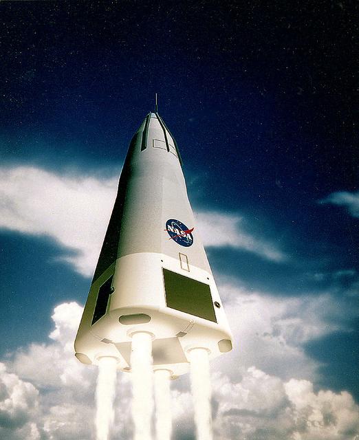
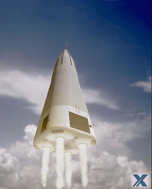
Pictured here is an artist's depiction of Rockwell's Vertical Landing Single-Stage-to-Orbit (SSTO) Reusable Launch Vehicle (RLV) deploying a satellite concept. The development of the RLV is essential in the cost reduction of future space travel.
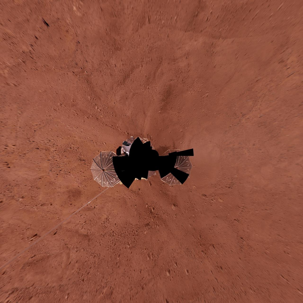
Full-Circle Color Panorama of Phoenix Landing Site on Northern Mars, Vertical Projection
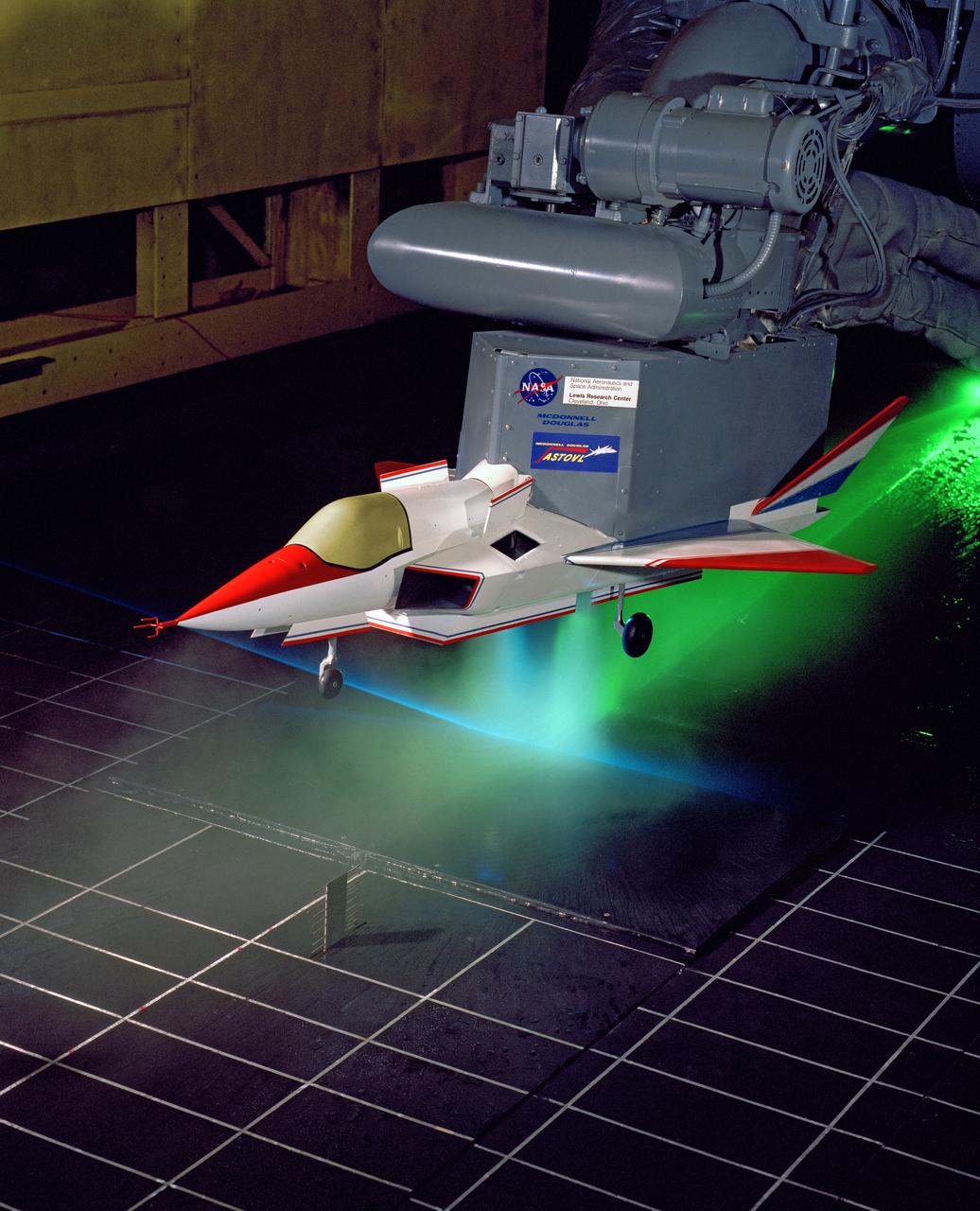
Supersonic Short Take Off Vertical Landing Hot Gas Ingestion Model Testing in the 9x15-foot Low Speed Wind Tunnel, LSWT
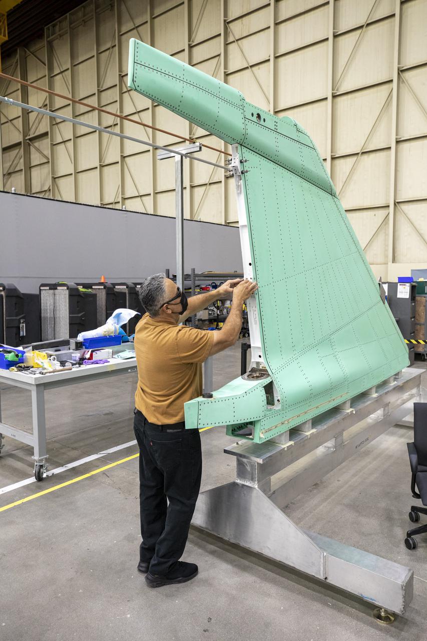
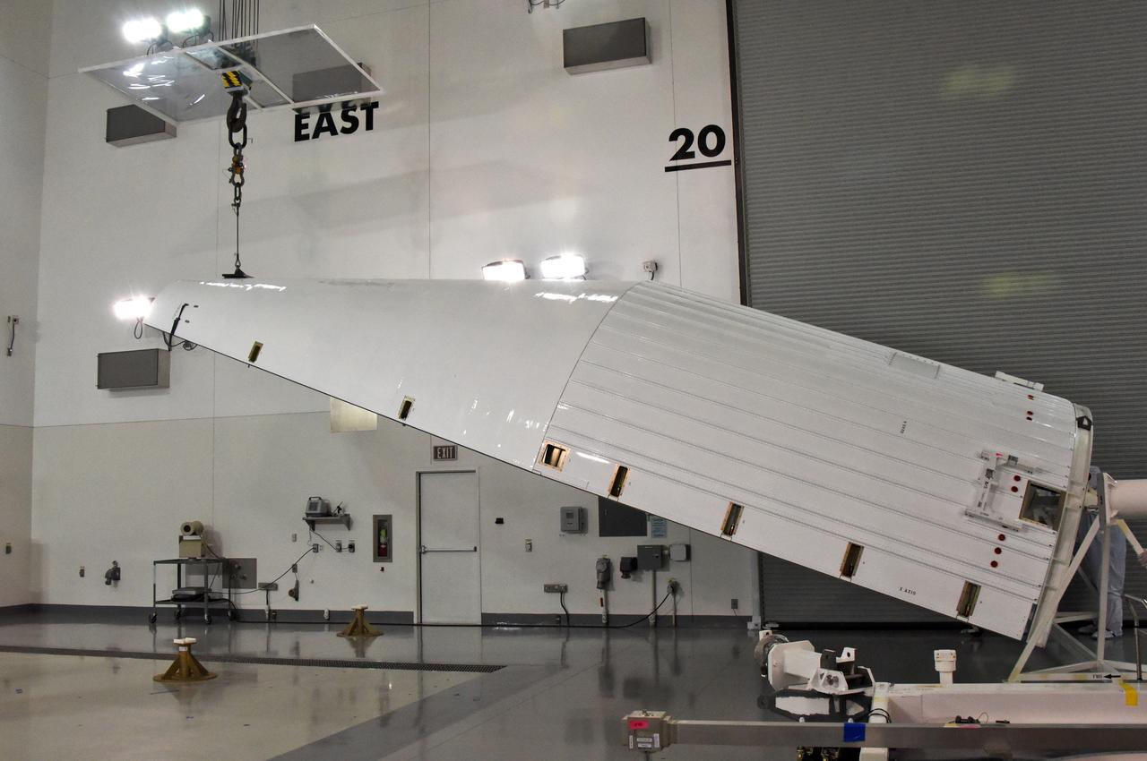
A technician is shown working on the X-59 vertical tail prior to installation at Lockheed Martin Skunk Works in Palmdale, California. The aircraft will fly to demonstrate the ability to fly supersonic while reducing the loud sonic boom to a quiet sonic thump. Lockheed Martin Photography By Garry Tice 1011 Lockheed Way, Palmdale, Ca. 93599 Event: SEG 530 Vertical Tail, Landing Gear Bay Doors Date: 4/28/2021
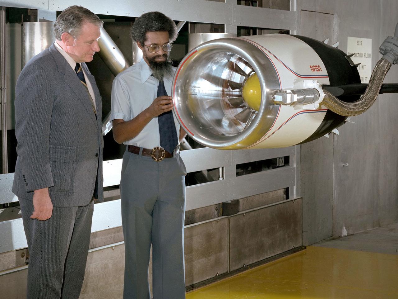
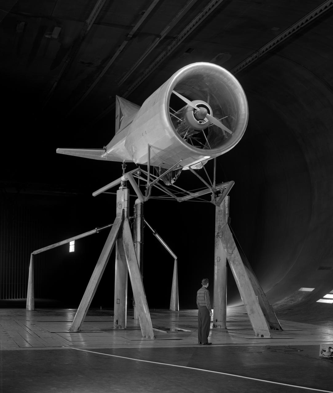
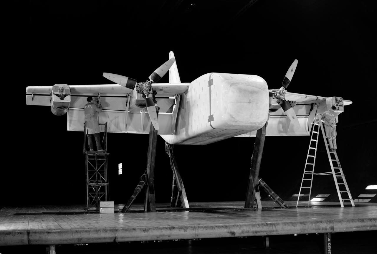
Center Director John McCarthy, left, and researcher Al Johns pose with a one-third scale model of a Grumman Aerospace tilt engine nacelle for Vertical and Short Takeoff and Landing (V/STOL) in the 9- by 15-Foot Low Speed Wind Tunnel at the National Aeronautics and Space Administration (NASA) Lewis Research Center. Lewis researchers had been studying tilt nacelle and inlet issues for several years. One area of concern was the inlet flow separation during the transition from horizontal to vertical flight. The separation of air flow from the inlet’s internal components could significantly stress the fan blades or cause a loss of thrust. In 1978 NASA researchers Robert Williams and Al Johns teamed with Grumman’s H.C. Potonides to develop a series of tests in the Lewis 9- by 15-foot tunnel to study a device designed to delay the flow separation by blowing additional air into the inlet. A jet of air, supplied through the hose on the right, was blown over the inlet surfaces. The researchers verified that the air jet slowed the flow separation. They found that the blowing on boundary layer control resulted in a doubling of the angle-of-attack and decreases in compressor blade stresses and fan distortion. The tests were the first time the concept of blowing air for boundary layer control was demonstrated. Boundary layer control devices like this could result in smaller and lighter V/STOL inlets.
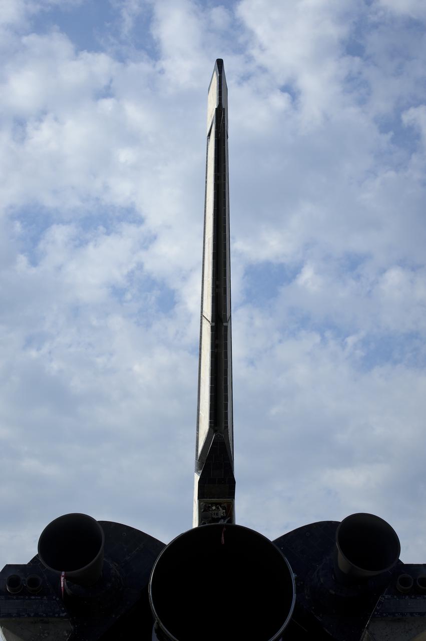
The vertical tail of the space shuttle Atlantis is seen at the Kennedy Space Center Shuttle Landing Facility (SLF) shortly after Atlantis (STS-135) landed early Thursday morning, July 21, 2011, in Cape Canaveral, Fla. Overall, Atlantis spent 307 days in space and traveled nearly 126 million miles during its 33 flights. Atlantis, the fourth orbiter built, launched on its first mission on Oct. 3, 1985. Photo Credit: (NASA/Bill Ingalls)
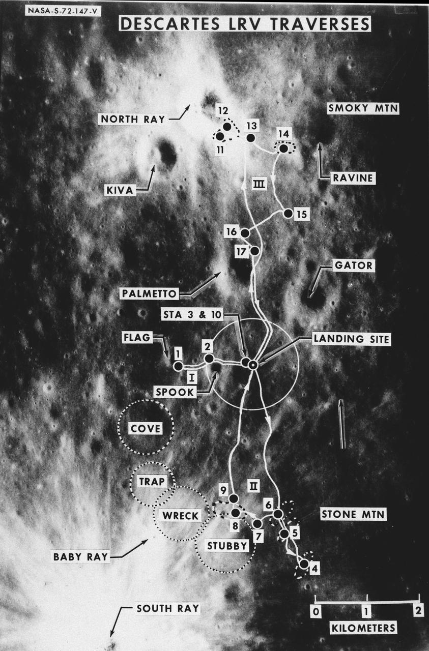
S72-00147 (January 1972) --- An almost vertical view of the Apollo 16 Descartes landing area, as photographed from the Apollo 14 spacecraft. Overlays are provided to point out extravehicular activity (EVA) Lunar Roving Vehicle (LRV) traverse routes and the nicknames of features. Hold picture with South Ray Crater in lower left corner. North will then be at the top. The Roman numerals indicate EVA numbers and the Arabic numbers point out stations or traverse stops.
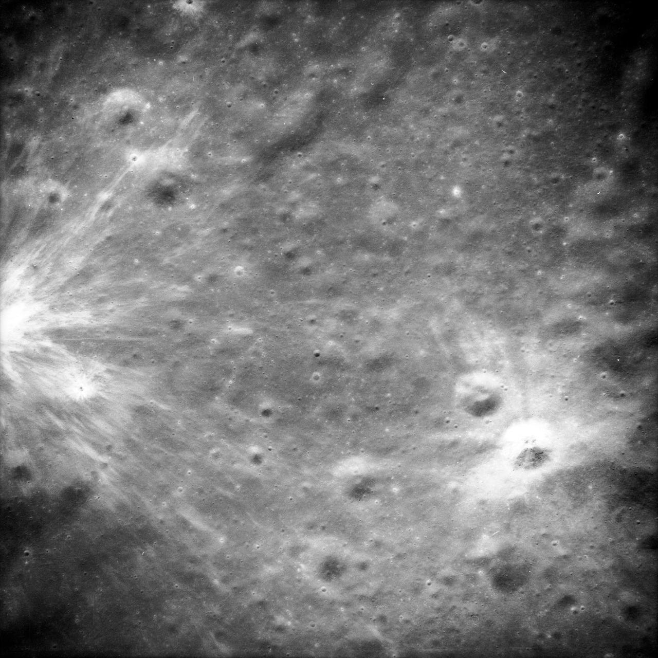
AS14-69-9523 (February 1971) --- This 500mm vertical frame taken from the Apollo 14 spacecraft is of the Apollo 16 proposed landing site "Descartes". The actual location of the target area is near the center of the picture. This photograph was taken on revolution 27 with a 56 degree sun angle. The large bright crater is approximately one kilometer in diameter and has a distinctive ray pattern which serves as an excellent landmark.
A spectrally resolved Rayleigh/Mie scattering diagnostic was developed to measure temperature and wingspan wise velocity in the vicinity of an ASTOVL aircraft model tested in the Lewis, now Glenn, 9x15 Low Speed Wind Tunnel. This was done for the Phase III hot gas ingestion study of ground-effect flow-field on such aircraft during hover or vertical landing.
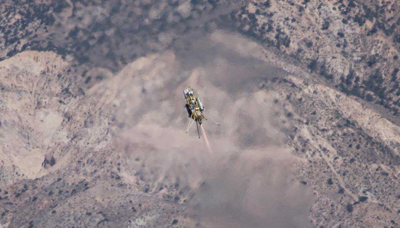
A Xombie technology demonstrator from Masten Space Systems, Mojave, Calif., ascends from its pad at Mojave Air and Space Port on a test for NASA Jet Propulsion Laboratory. The vehicle is a vertical-takeoff, vertical-landing experimental rocket.

S71-44150 (February 1971) --- A vertical view of the Apollo 16 landing site located in the Descartes area on the lunar nearside. The overlay indicates the location of the proposed touchdown point for the Apollo 16 Lunar Module (LM). Descartes is located west of the Sea of Nectar and southwest of the Sea of Tranquility. This photograph was taken with a 500mm lens camera from lunar orbit by the Apollo 16 crew. Astronauts John W. Young, commander; and Charles M. Duke Jr., lunar module pilot; descended in the Apollo 16 LM "Orion" to explore the Descartes highlands landing site on the moon. Astronaut Thomas K. Mattingly II, command module pilot, remained with the Command and Service Modules (CSM) "Casper" in lunar orbit.
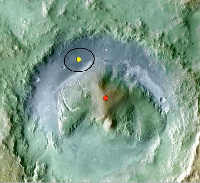
Color coding in this image of Gale Crater on Mars represents differences in elevation. The vertical difference from a low point inside the landing ellipse for NASA Mars Science Laboratory yellow dot to a high point on the mountain inside the crater.
Masten Space Systems vertical takeoff vertical landing rocket launched September 10, 2020 to flight test NASA-licensed Psionic navigation doppler lidar technology that enables precision landing on celestial bodies where GPS for navigation only available on Earth is not an option.
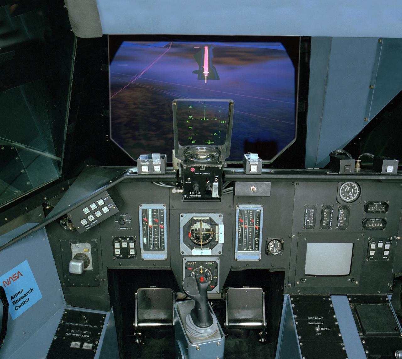
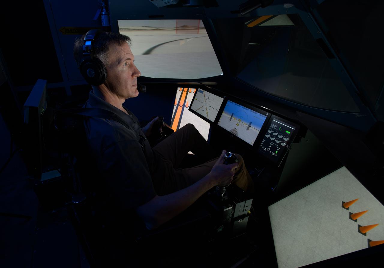
NASA Ames VMS (Vertical Motion simulator) S-cab Space Shuttle sim with out the window views 'night landing'
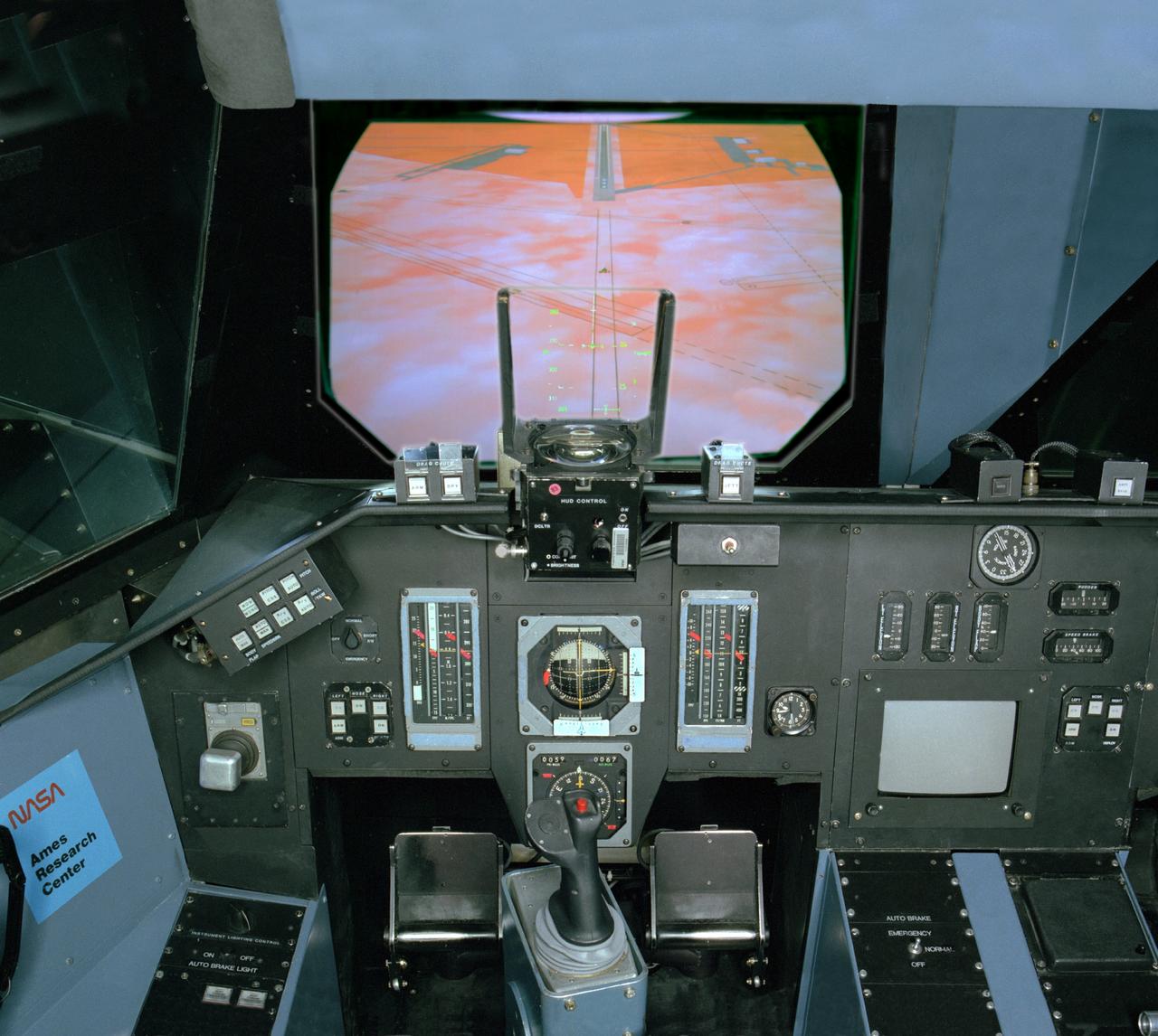
NASA Ames VMS (Vertical Motion simulator) S-cab Space Shuttle sim with out the window views 'DFRC landing'
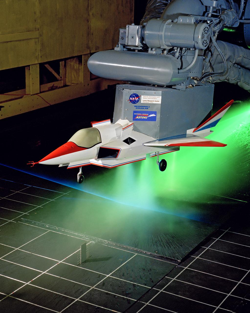
SUPERSONIC SHORT TAKE OFF Vertical LANDING HOT GAS INGESTION MODEL 9X15 WIND TUNNEL
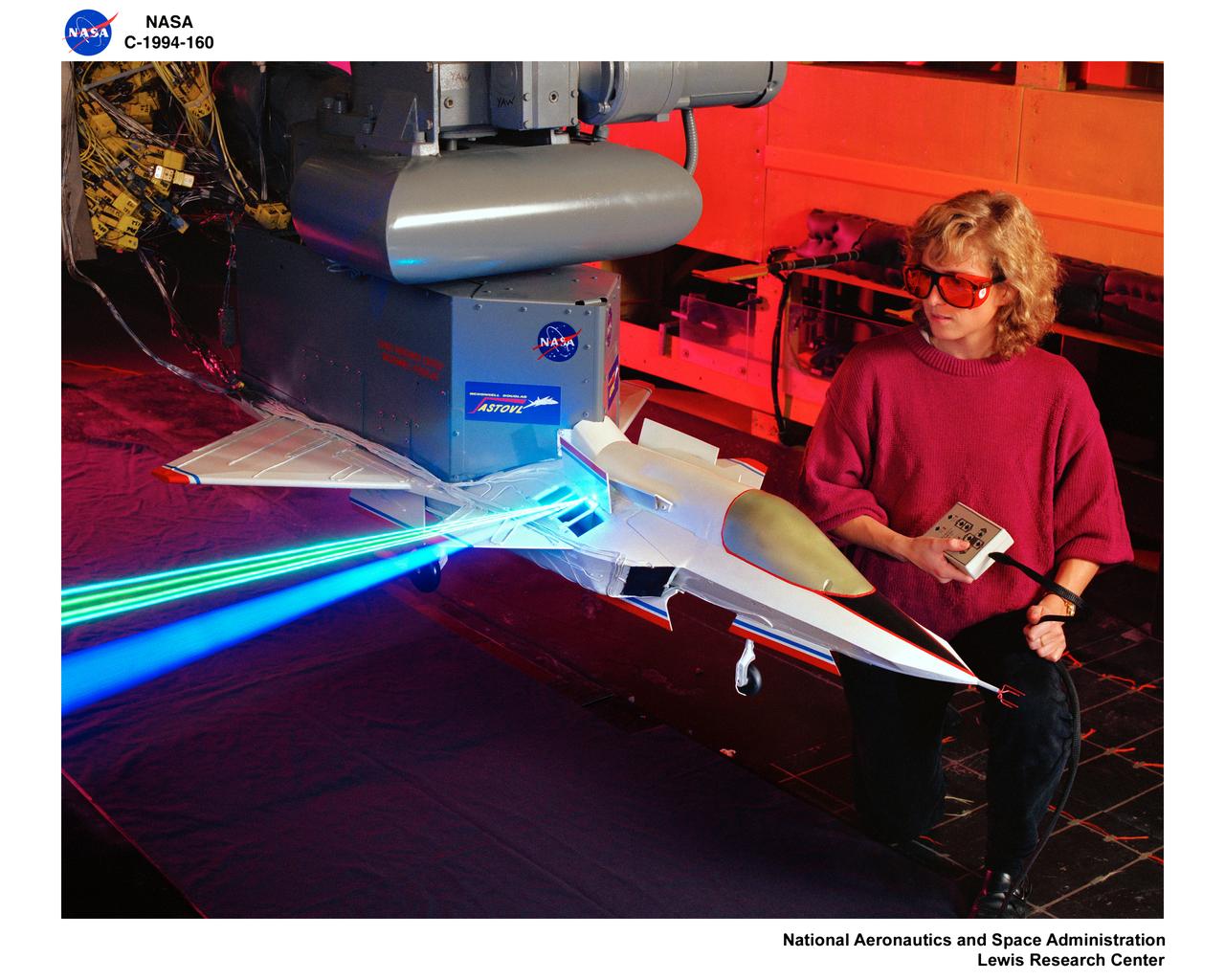
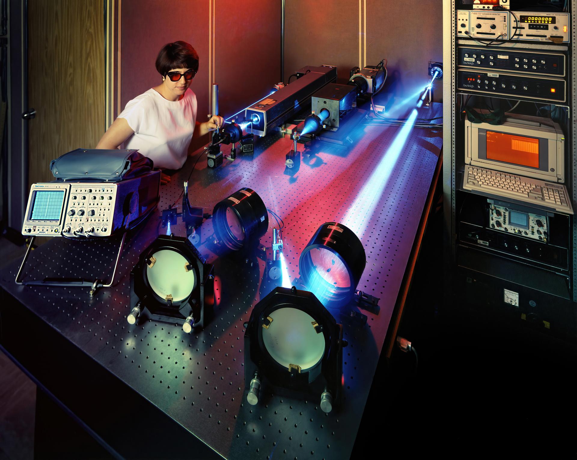
LASER Velocimetry System for Flow Measurement. Advanced Short Takeoff and Vertical Landing, ASTOVL model n the 9x15 foot Low Speed Wind Tunnel, LSWT
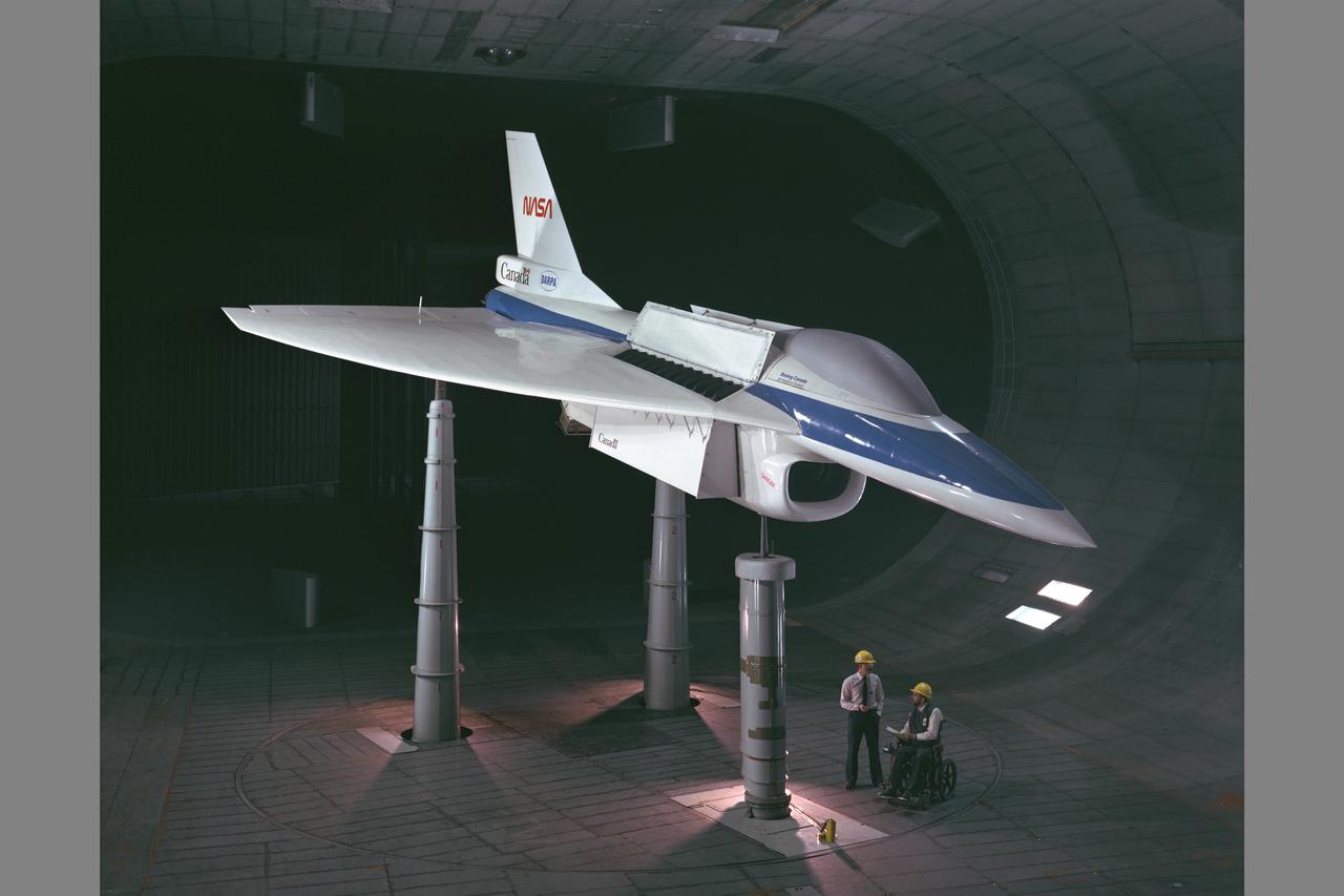
E-7 STOVL fighter model testing in Ames 40x80ft Subsonic wind tunnel. Investigating Supersonic Short Take-off and Vertical Landing (STOVL) technology.
Collins Aerodyne VTOL Vertical take off and landing model in the 40x80 foot wind tunnel at NASA's Ames Research Center. Designed by Alexander Lippisch.
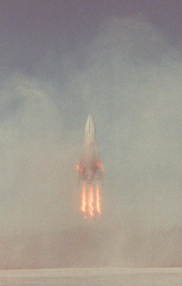
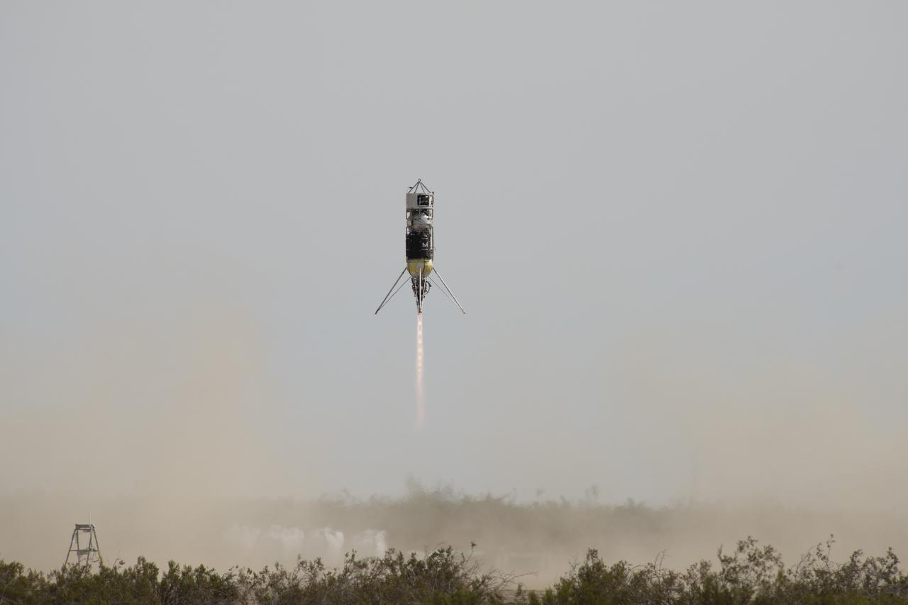
The Delta Clipper-Experimental Advanced (DC-XA) is a single-stage-to-orbit, vertical takeoff / vertical landing launch vehicle concept, whose development was geared to significantly reduce launch cost and provided a test bed for NASA Reusable Launch Vehicle (RLV) technology. This photograph shows the descending vehicle landing during the first successful test flight at White Sands Missile Range, New Mexico. The program was discontinued in 2003.

Researchers from NASA's Jet Propulsion Laboratory in Southern California and the National Oceanic and Atmospheric Administration (NOAA) analyzed vertical land motion – also known as uplift and subsidence – along the California coast between 2015 and 2023. They detailed where land beneath major coastal cities, including parts of San Francisco, Los Angeles, and San Diego, is sinking (indicated in blue in this visualization of the data). Locations of uplift (shown in red) were also observed. Causes for the motion include human-driven activities such as groundwater withdrawal and wastewater injection as well as natural dynamics like tectonic activity. Understanding these local elevation changes can help communities adapt to rising sea levels in their area. The researchers pinpointed hot spots – including cities, beaches, and aquifers – at greater exposure to rising seas in coming decades. Sea level rise can exacerbate issues like nuisance flooding and saltwater intrusion. To gather the data, the researchers employed a remote sensing technique called interferometric synthetic aperture radar (InSAR), which combines two or more 3D observations of the same region to reveal surface motion down to fractions of inches. They used the radars on the ESA (European Space Agency) Sentinel-1 satellites, as well as motion velocity data from ground-based receiving stations in the Global Navigation Satellite System. https://photojournal.jpl.nasa.gov/catalog/PIA25530
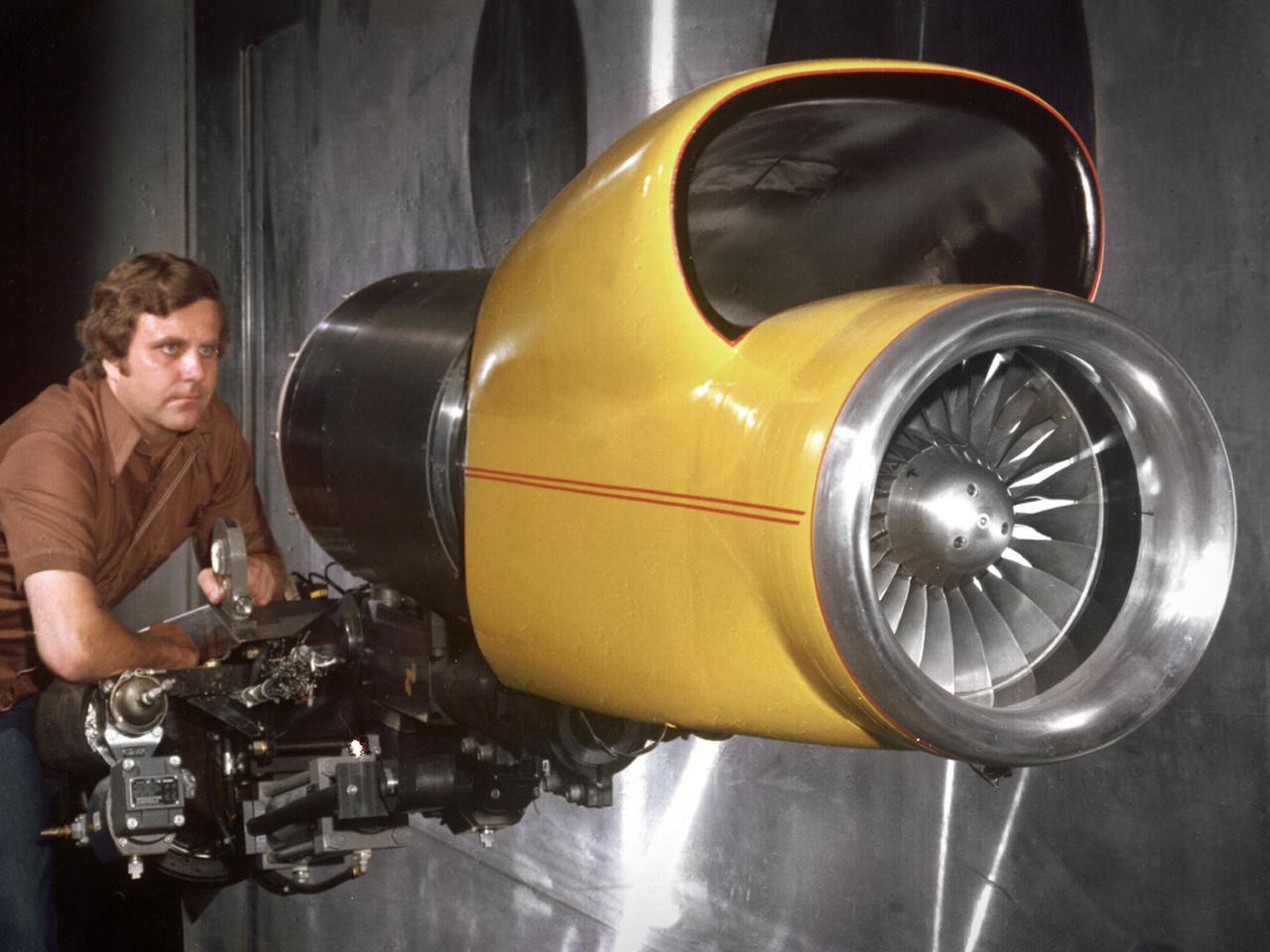
A technician checks a 0.25-scale engine model of a Vought Corporation V-530 engine in the test section of the 10- by 10-Foot Supersonic Wind Tunnel at the National Aeronautics and Space Administration (NASA) Lewis Research Center. Vought created a low-drag tandem-fan Vertical/Short and Takeoff and Landing (V/STOL) engine in the mid-1970s, designated as the V-530. The first fan on the tandem-fan engine was supplied with air through a traditional subsonic inlet, seen on the lower front of the engine. The air was exhausted through the nacelle during normal flight and directed down during takeoffs. The rear fan was supplied by the oval-shaped top inlet during all phases of the flight. The second fan exhausted its air through a rear vectorable nozzle. NASA Lewis and Vought partnered in the late 1970s to collect an array of inlet and nozzle design information on the tandem fan engines for the Navy. Vought created this .25-scale model of the V-530 for extensive testing in Lewis' 10- by 10-foot tunnel. During an early series of tests, the front fan was covered, and a turbofan simulator was used to supply air to the rear fan. The researchers then analyzed the performance of only the front fan inlet. During the final series of tests, the flow from the front fan was used to supply airflow to the rear fan. The researchers studied the inlet's recovery, distortion, and angle-of-attack limits over various flight conditions.
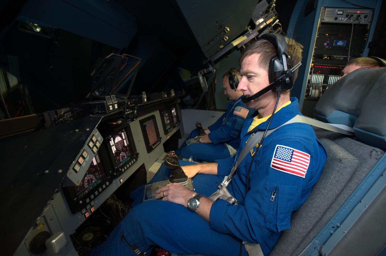
STS-135 astronaut training in the Vertical Motion Simulator, Ames Research Center, Moffett Field, CA. Mission Chris Ferguson commander in forground, Doug Hurley, pilot in background are in VMS S-cab cockpit for simulated landing practice under a variety of landing sites and conditions.
Michael Feary pilots a simulated electric vertical takeoff and landing, or eVTOL, aircraft in the VMS’s R-Cab during the AFCM subproject simulation FAA-2 flight tests in the VMS, N243.
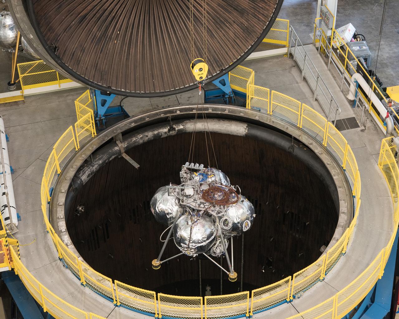
NASA's Morpheus Project has developed and tested a prototype planetary lander capable of vertical takeoff and landing. This is an image of the lander being installed in the B-2 facility for testing at Plum Brook Station.
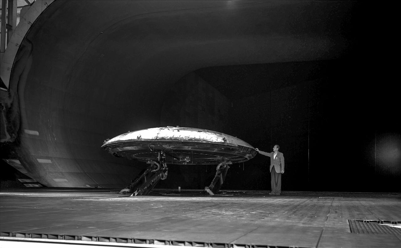
Rear view of the Avrocar without the tail, with ground board and variable height struts. The air force wanted to test the design of a flying saucer with vertical takeoff and landing capability. The design proved unstable without the tail.
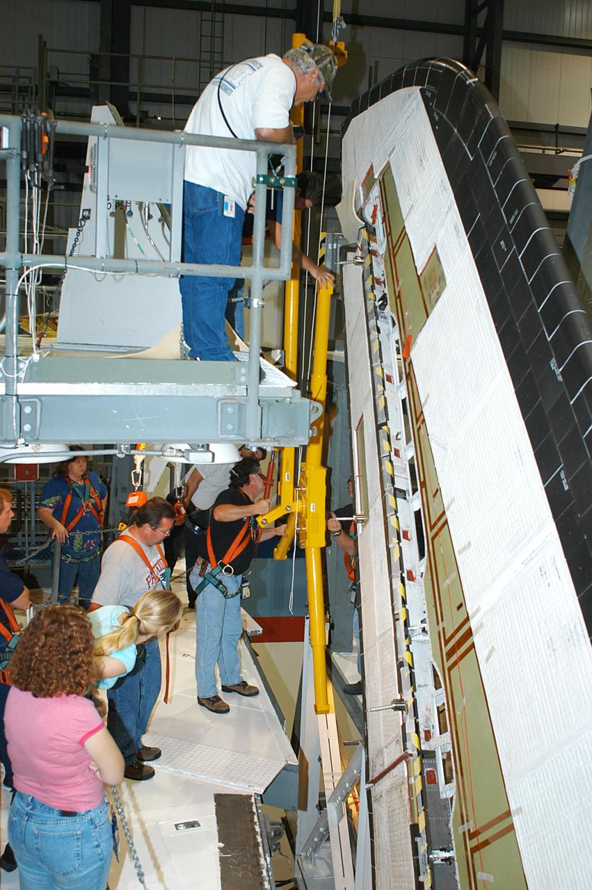
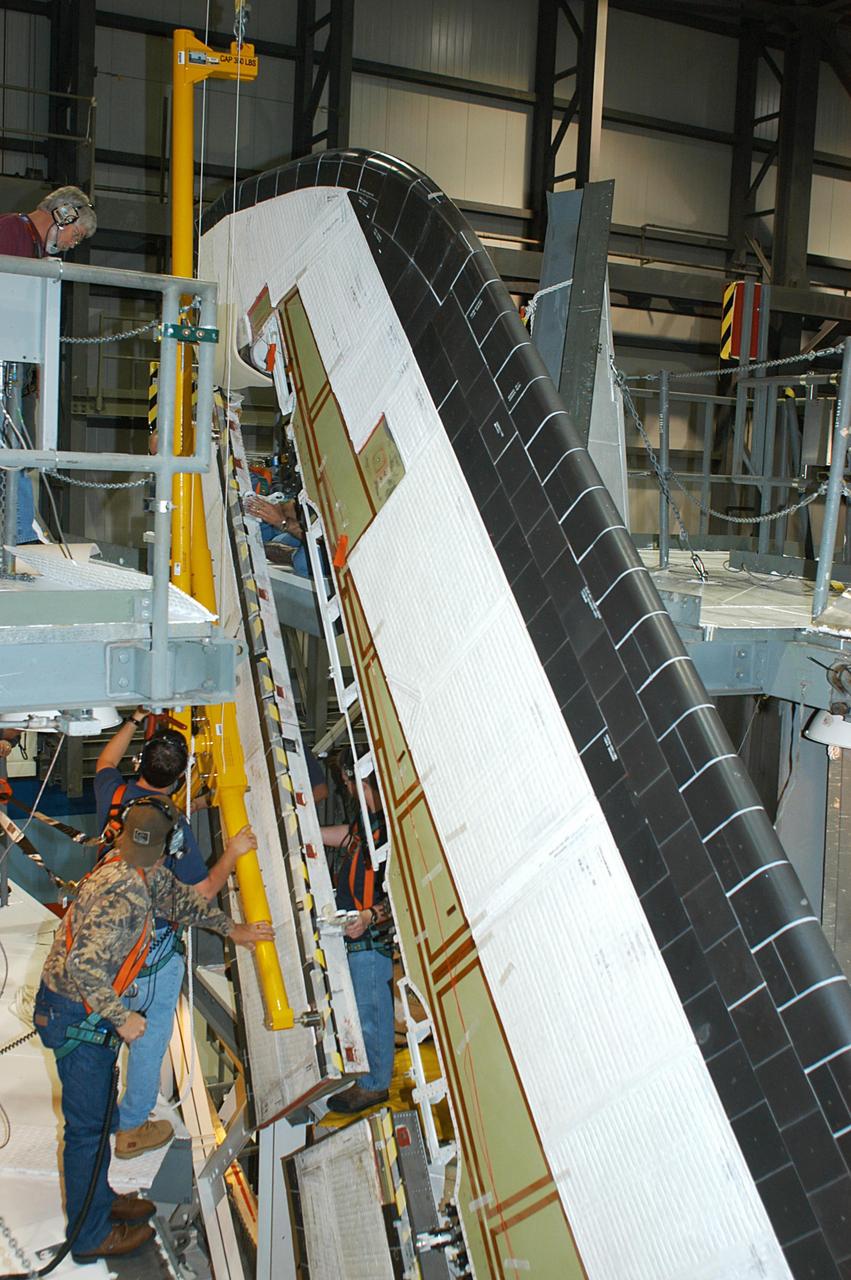
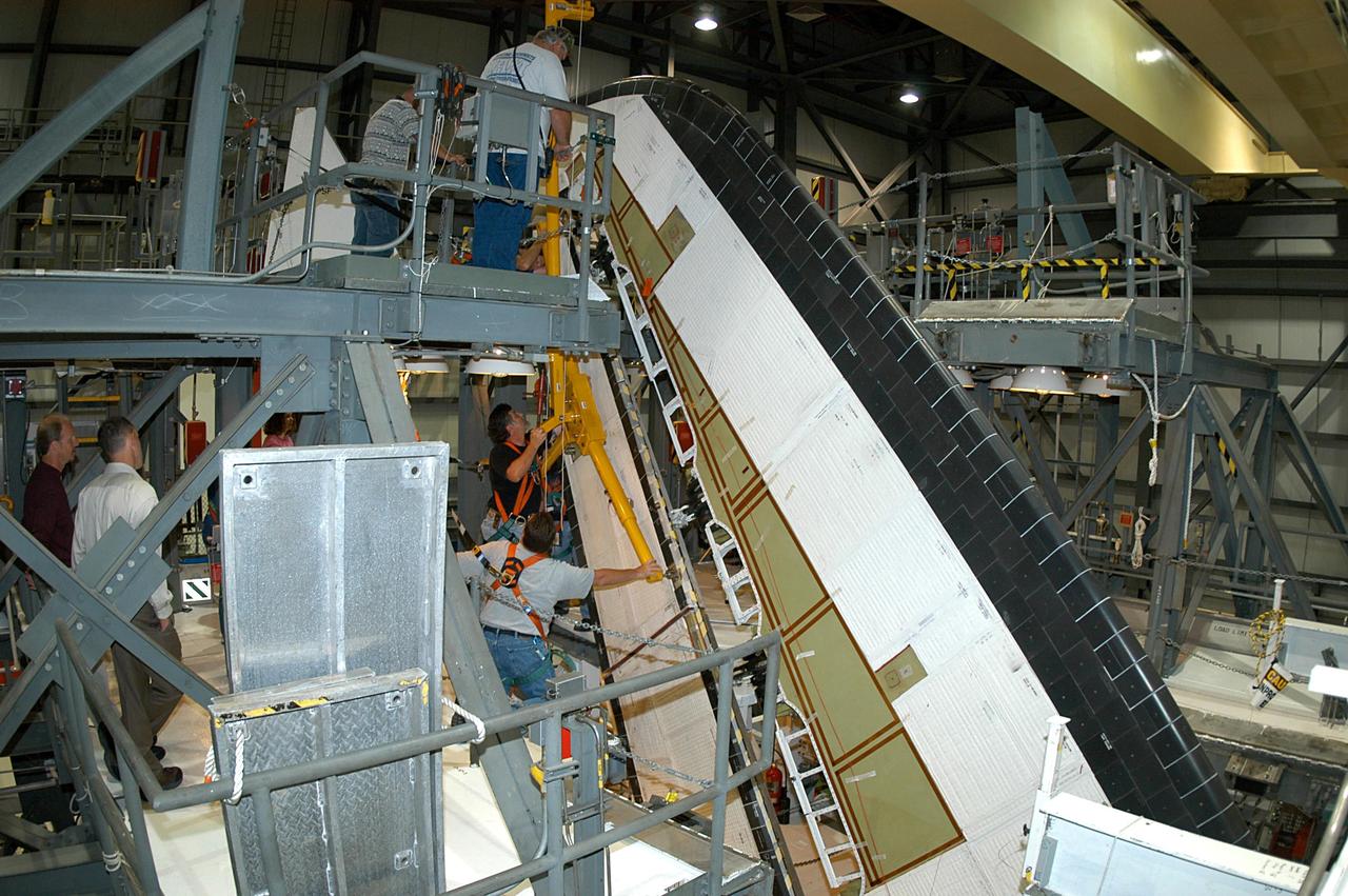
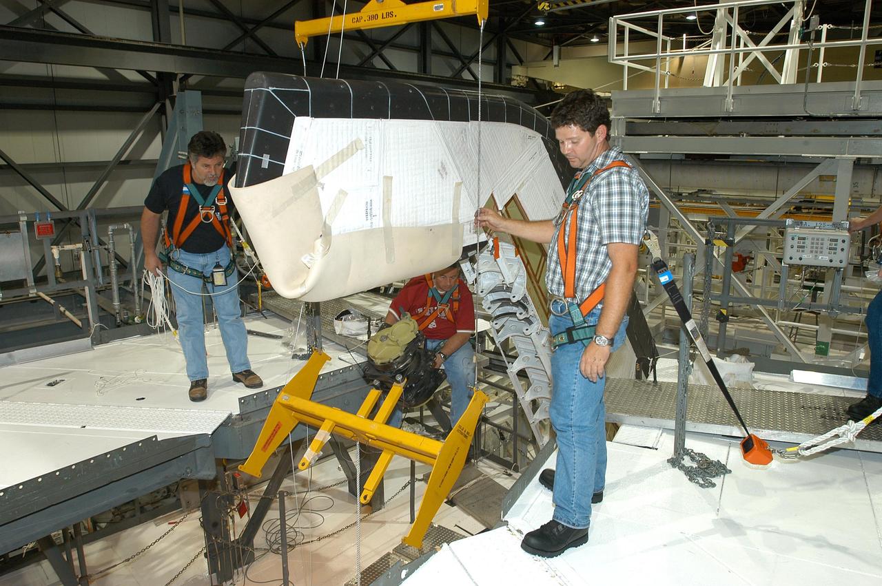
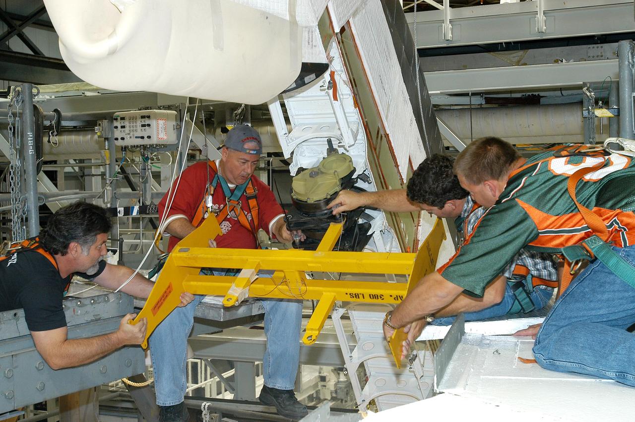
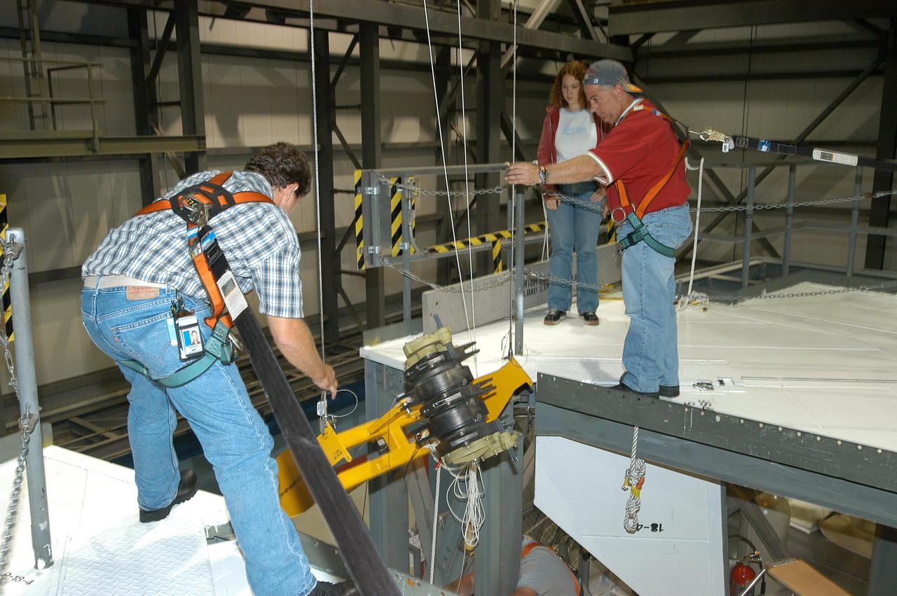
KENNEDY SPACE CENTER, FLA. -- In the Orbiter Processing Facility, a worker (below the upper framework) begins connecting a device to remove the Rudder Speed Brake panel on the vertical tail of orbiter Atlantis. The Rudder Speed Brake is being removed for inspection and maintenance prior to Return to Flight. The vertical tail consists of a structural fin surface made of aluminum, the Rudder Speed Brake surface, a tip and a lower trailing edge. The rudder splits into two halves to serve as a speed brake. The vertical tail and Rudder Speed Brake are covered with a reusable thermal protection system. The Rudder Speed Brake is used to guide and slow the Shuttle as it comes in for a landing.
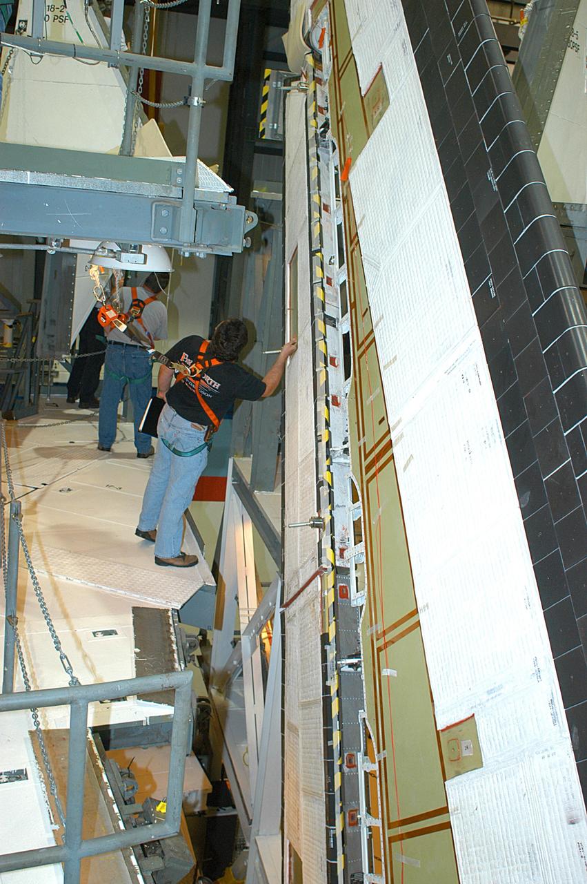
KENNEDY SPACE CENTER, FLA. -- In the Orbiter Processing Facility, workers remove the Rudder Speed Brake panel on the vertical tail of the orbiter Atlantis. The Rudder Speed Brake is being removed for inspection and maintenance prior to Return to Flight. The vertical tail consists of a structural fin surface made of aluminum, the Rudder Speed Brake surface, a tip and a lower trailing edge. The rudder splits into two halves to serve as a speed brake. The vertical tail and Rudder Speed Brake are covered with a reusable thermal protection system. The Rudder Speed Brake is used to guide and slow the Shuttle as it comes in for a landing.
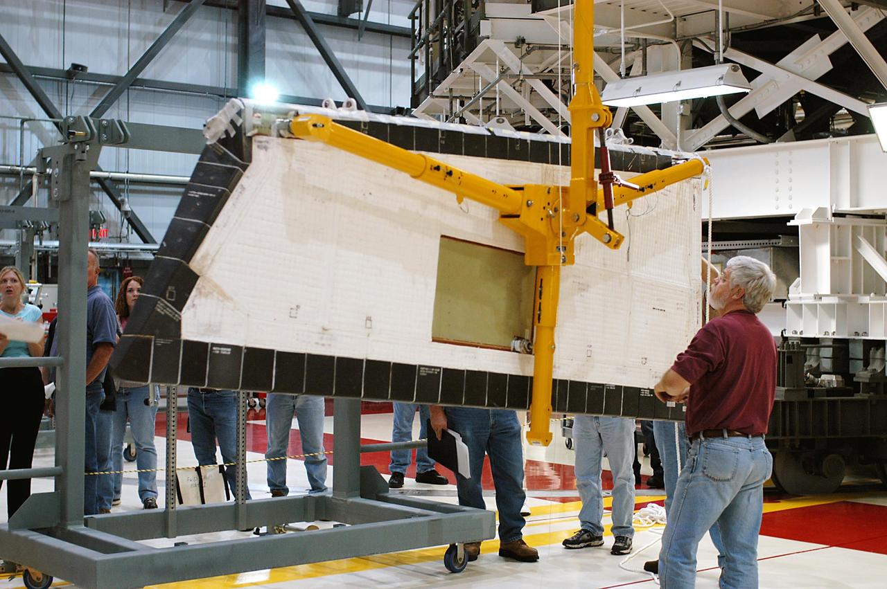
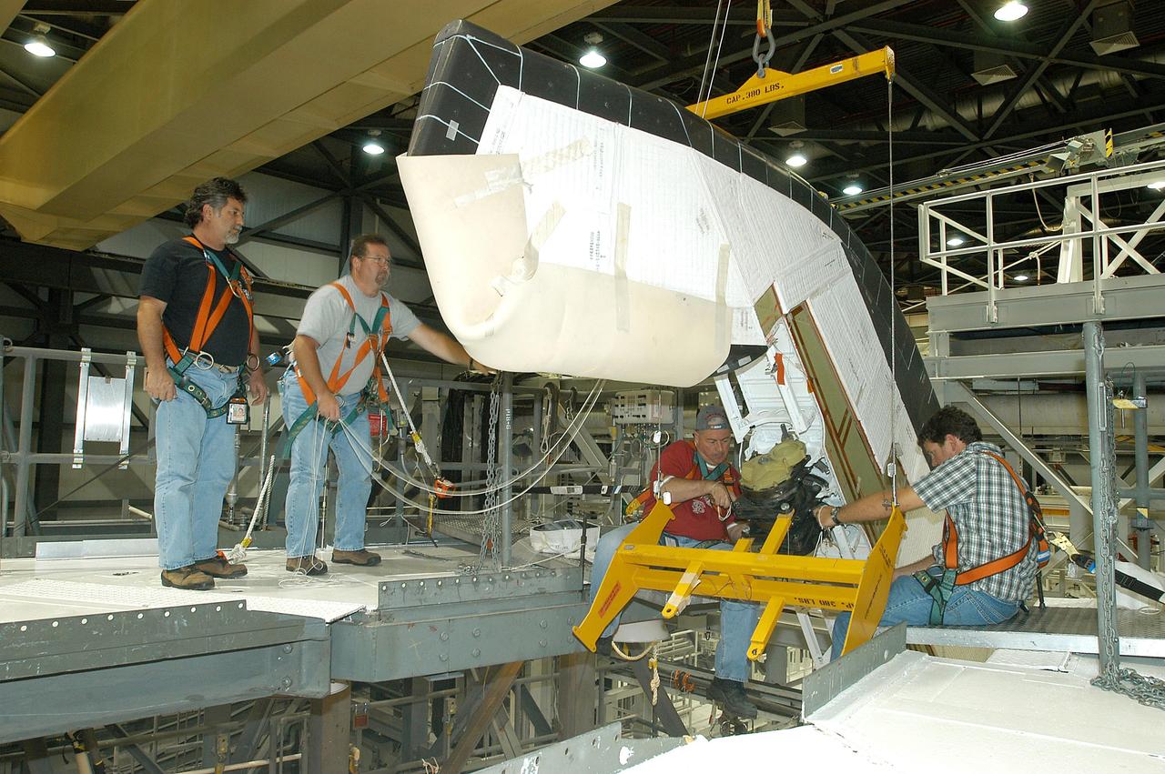
KENNEDY SPACE CENTER, FLA. -- In the Orbiter Processing Facility, workers lower Atlantis’ Rudder Speed Brake panel onto a stand after removing the panel from the vertical tail. The Rudder Speed Brake is being removed for inspection and maintenance prior to Return to Flight. The vertical tail consists of a structural fin surface made of aluminum, the Rudder Speed Brake surface, a tip and a lower trailing edge. The rudder splits into two halves to serve as a speed brake. The vertical tail and Rudder Speed Brake are covered with a reusable thermal protection system. The Rudder Speed Brake is used to guide and slow the Shuttle as it comes in for a landing.
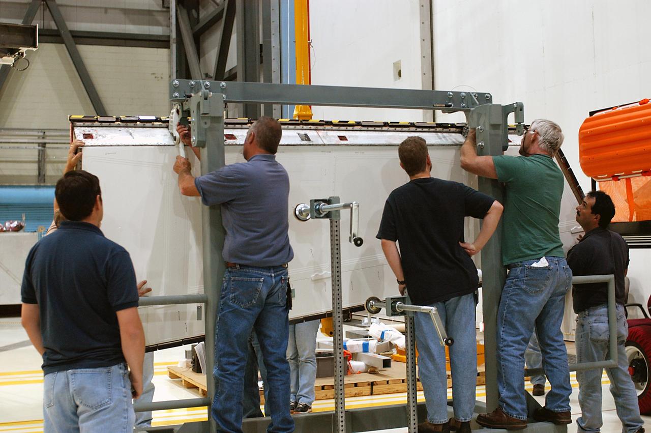
KENNEDY SPACE CENTER, FLA. -- In the Orbiter Processing Facility, workers attach Atlantis’ Rudder Speed Brake panel to a stand after removing the panel from the vertical tail. The Rudder Speed Brake is being removed for inspection and maintenance prior to Return to Flight. The vertical tail consists of a structural fin surface made of aluminum, the Rudder Speed Brake surface, a tip and a lower trailing edge. The rudder splits into two halves to serve as a speed brake. The vertical tail and Rudder Speed Brake are covered with a reusable thermal protection system. The Rudder Speed Brake is used to guide and slow the Shuttle as it comes in for a landing.
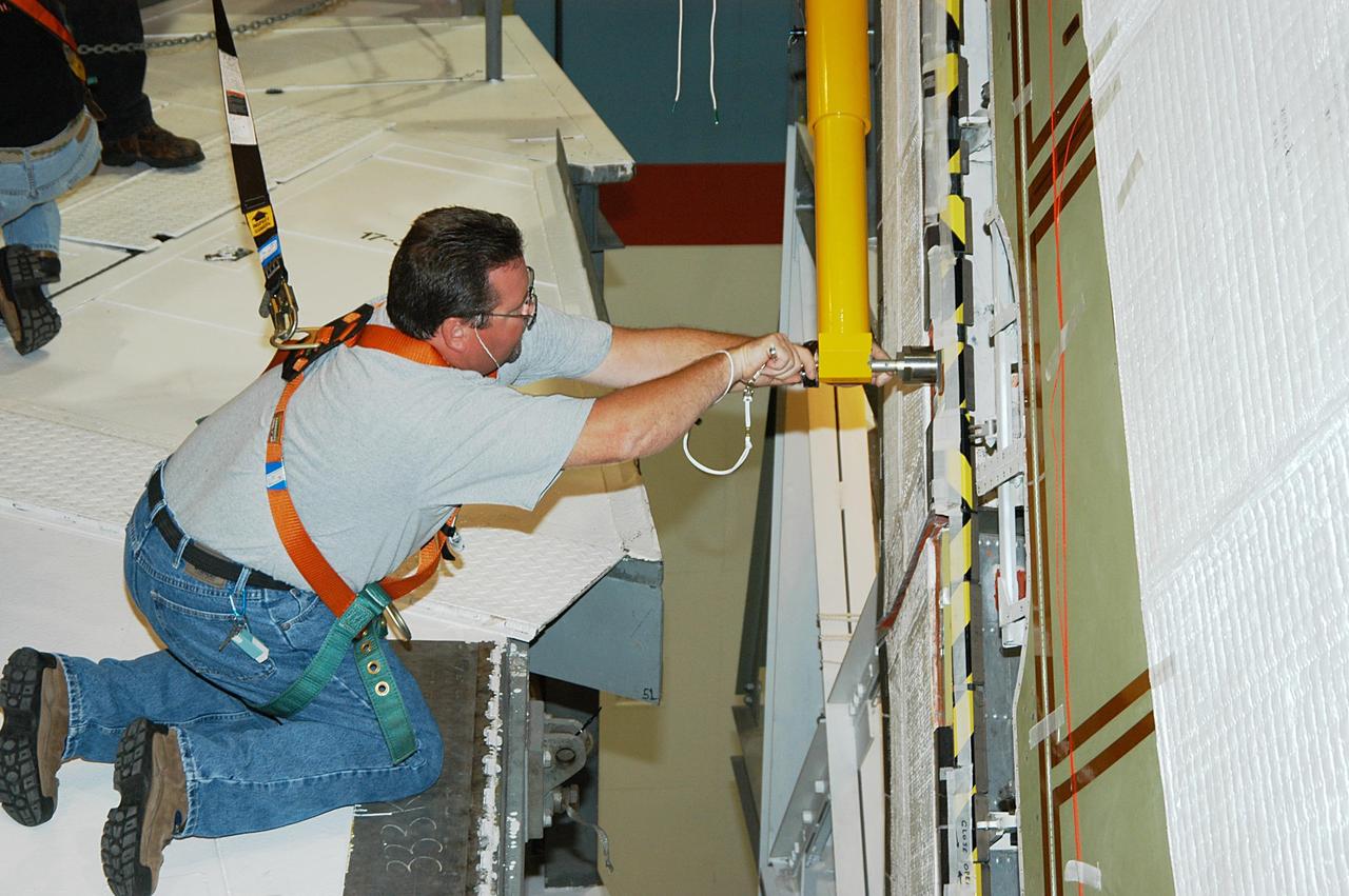
KENNEDY SPACE CENTER, FLA. -- In the Orbiter Processing Facility, a worker tightens a fitting on the device being used to remove the Rudder Speed Brake panel on the vertical tail of the orbiter Atlantis. The Rudder Speed Brake is being removed for inspection and maintenance prior to Return to Flight. The vertical tail consists of a structural fin surface made of aluminum, the Rudder Speed Brake surface, a tip and a lower trailing edge. The rudder splits into two halves to serve as a speed brake. The vertical tail and Rudder Speed Brake are covered with a reusable thermal protection system. The Rudder Speed Brake is used to guide and slow the Shuttle as it comes in for a landing.

KENNEDY SPACE CENTER, FLA. -- In the Orbiter Processing Facility, workers attach Atlantis’ Rudder Speed Brake panel to a stand after removing the panel from the vertical tail. The Rudder Speed Brake is being removed for inspection and maintenance prior to Return to Flight. The vertical tail consists of a structural fin surface made of aluminum, the Rudder Speed Brake surface, a tip and a lower trailing edge. The rudder splits into two halves to serve as a speed brake. The vertical tail and Rudder Speed Brake are covered with a reusable thermal protection system. The Rudder Speed Brake is used to guide and slow the Shuttle as it comes in for a landing.
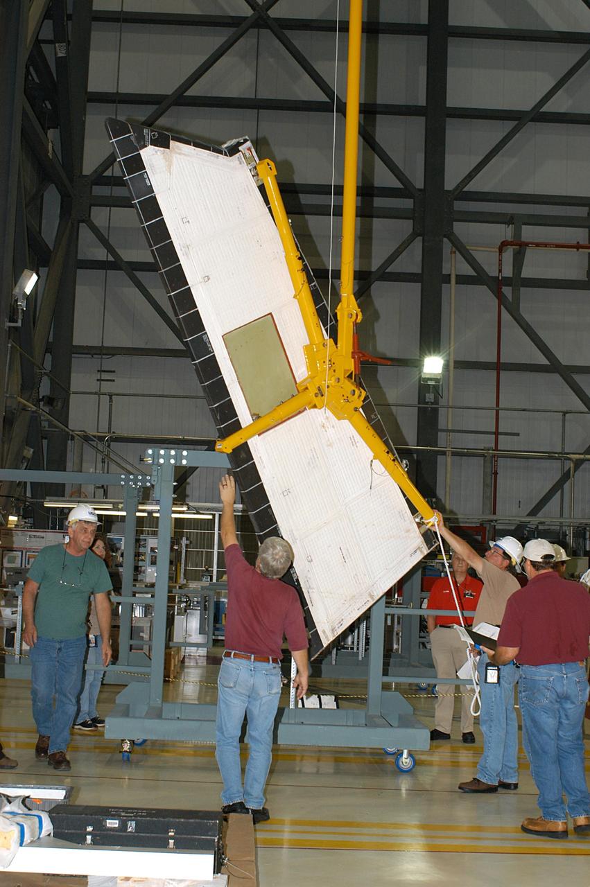
KENNEDY SPACE CENTER, FLA. -- In the Orbiter Processing Facility, workers lower Atlantis’ Rudder Speed Brake panel toward the floor after removing the panel from the vertical tail. The Rudder Speed Brake is being removed for inspection and maintenance prior to Return to Flight. The vertical tail consists of a structural fin surface made of aluminum, the Rudder Speed Brake surface, a tip and a lower trailing edge. The rudder splits into two halves to serve as a speed brake. The vertical tail and Rudder Speed Brake are covered with a reusable thermal protection system. The Rudder Speed Brake is used to guide and slow the Shuttle as it comes in for a landing.
KENNEDY SPACE CENTER, FLA. -- In the Orbiter Processing Facility, a technician looks at the Rudder Speed Brake panel on the vertical tail of orbiter Atlantis. The Rudder Speed Brake is being removed for inspection and maintenance prior to Return to Flight. The vertical tail consists of a structural fin surface made of aluminum, the Rudder Speed Brake surface, a tip and a lower trailing edge. The rudder splits into two halves to serve as a speed brake. The vertical tail and Rudder Speed Brake are covered with a reusable thermal protection system. The Rudder Speed Brake is used to guide and slow the Shuttle as it comes in for a landing.
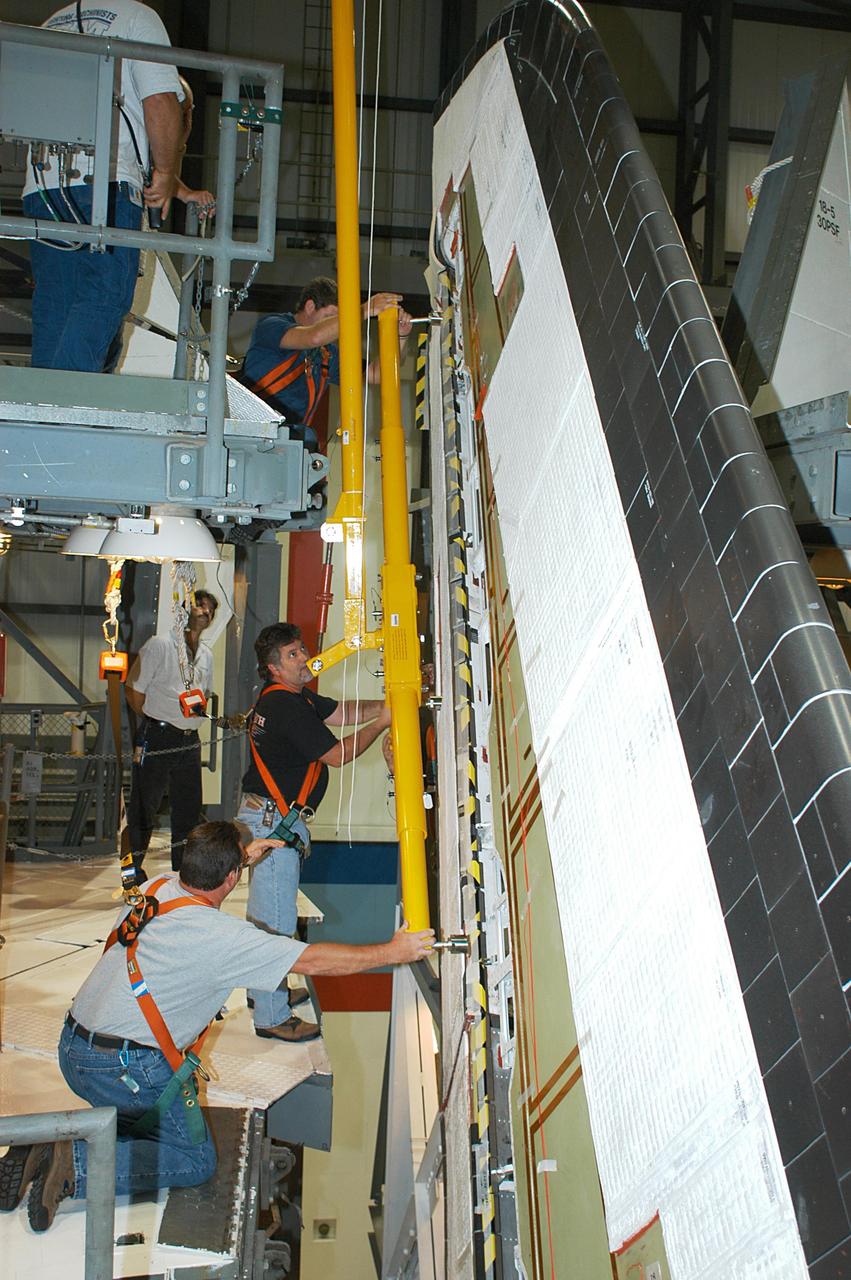
KENNEDY SPACE CENTER, FLA. -- In the Orbiter Processing Facility, workers connect a device onto the vertical tail of the orbiter Atlantis to remove the Rudder Speed Brake panel. The Rudder Speed Brake is being removed for inspection and maintenance prior to Return to Flight. The vertical tail consists of a structural fin surface made of aluminum, the Rudder Speed Brake surface, a tip and a lower trailing edge. The rudder splits into two halves to serve as a speed brake. The vertical tail and Rudder Speed Brake are covered with a reusable thermal protection system. The Rudder Speed Brake is used to guide and slow the Shuttle as it comes in for a landing.
KENNEDY SPACE CENTER, FLA. -- In the Orbiter Processing Facility, workers begin removing the Rudder Speed Brake panel on the vertical tail of the orbiter Atlantis. The Rudder Speed Brake is being removed for inspection and maintenance prior to Return to Flight. The vertical tail consists of a structural fin surface made of aluminum, the Rudder Speed Brake surface, a tip and a lower trailing edge. The rudder splits into two halves to serve as a speed brake. The vertical tail and Rudder Speed Brake are covered with a reusable thermal protection system. The Rudder Speed Brake is used to guide and slow the Shuttle as it comes in for a landing.
This is the McDornell Douglas CD-XA Reusable Launch Vehicle (RLV) concept. The Delta Clipper-Experimental (DC-X) was originally developed by McDonnell Douglas for the DOD. The DC-XA is a single-stage-to-orbit, vertical takeoff/vertical landing, launch vehicle concept, whose development is geared to significantly reduce launch cost and provided a test bed for NASA Reusable Launch Vehicle (RLV) technology as the Delta Clipper-Experimental Advanced (DC-XA). The program was discontinued in 2003.

The Shuttle Orbiter Enterprise atop a 747 landing at Redstone Arsenal Airfield for later Mated Vertical Ground Vibration tests (MVGVT) at Marshall Space Flight Center's Dynamic Test Stand. The tests marked the first time ever that the entire shuttle complement (including orbiter, external tank, and solid rocket boosters) were mated vertically.
Pictured here is a DC-XA Reusable Launch Vehicle (RLV) prototype concept with an RLV logo. The Delta Clipper-Experimental (DC-X) was originally developed by McDornell Douglas for the Department of Defense (DOD). The DC-XA is a single-stage-to-orbit, vertical takeoff/vertical landing, launch vehicle concept, whose development is geared to significantly reduce launch costs and will provide a test bed for NASA Reusable Launch Vehicle (RLV) technology as the Delta Clipper-Experimental Advanced (DC-XA).
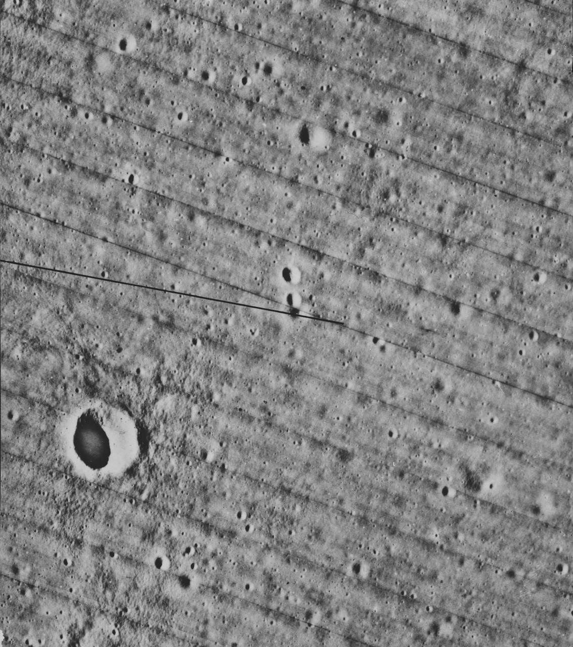
S70-54740 (December 1970) --- A lunar orbiter photograph showing a vertical view of the Apollo 14 landing site located in the Fra Mauro highlands on the lunar nearside. The predicted landing point is 17 degrees 27 minutes 46 seconds west longitude and 3 degrees 40 minutes 19 seconds south latitude. North is toward the right side of the picture. Cone Crater, the largest lunar feature visible, is located near the northeast corner of the photograph. The landing point is between Triplet Crater and Doublet Crater in the center of the picture.
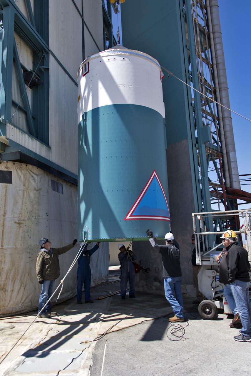
The United Launch Alliance Delta II interstage is lifted up at the Vertical Integration Facility at Space Launch Complex 2 on June 12, 2018, at Vandenberg Air Force Base in California. The interstage will be moved in and mated to the top of the booster, or first stage of the rocket. NASA's Ice, Cloud and land Elevation Satellite-2 (ICESat-2) will launch on the final Delta II rocket. ICESat-2 will measure the height of a changing Earth, one laser pulse at a time, 10,000 laser pulses a second. The satellite will carry a single instrument, the Advanced Topographic Laser Altimeter System. ICESat-2 will help scientists investigate why, and how much our planet's frozen and icy areas, called the cryosphere, is changing in a warming climate.
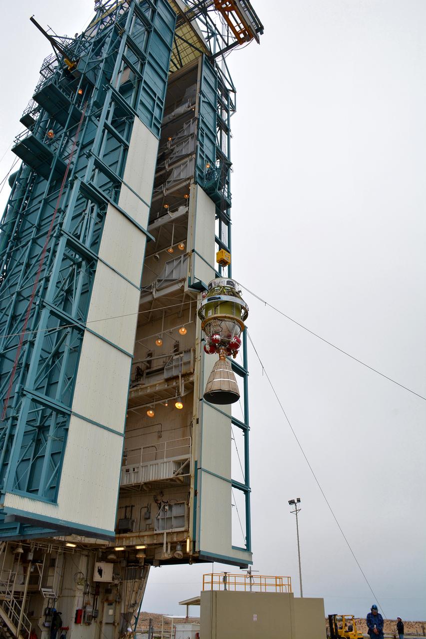
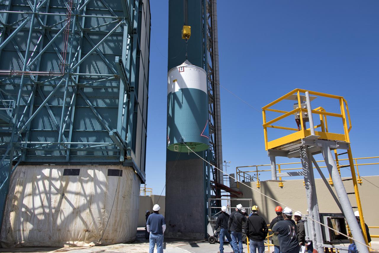
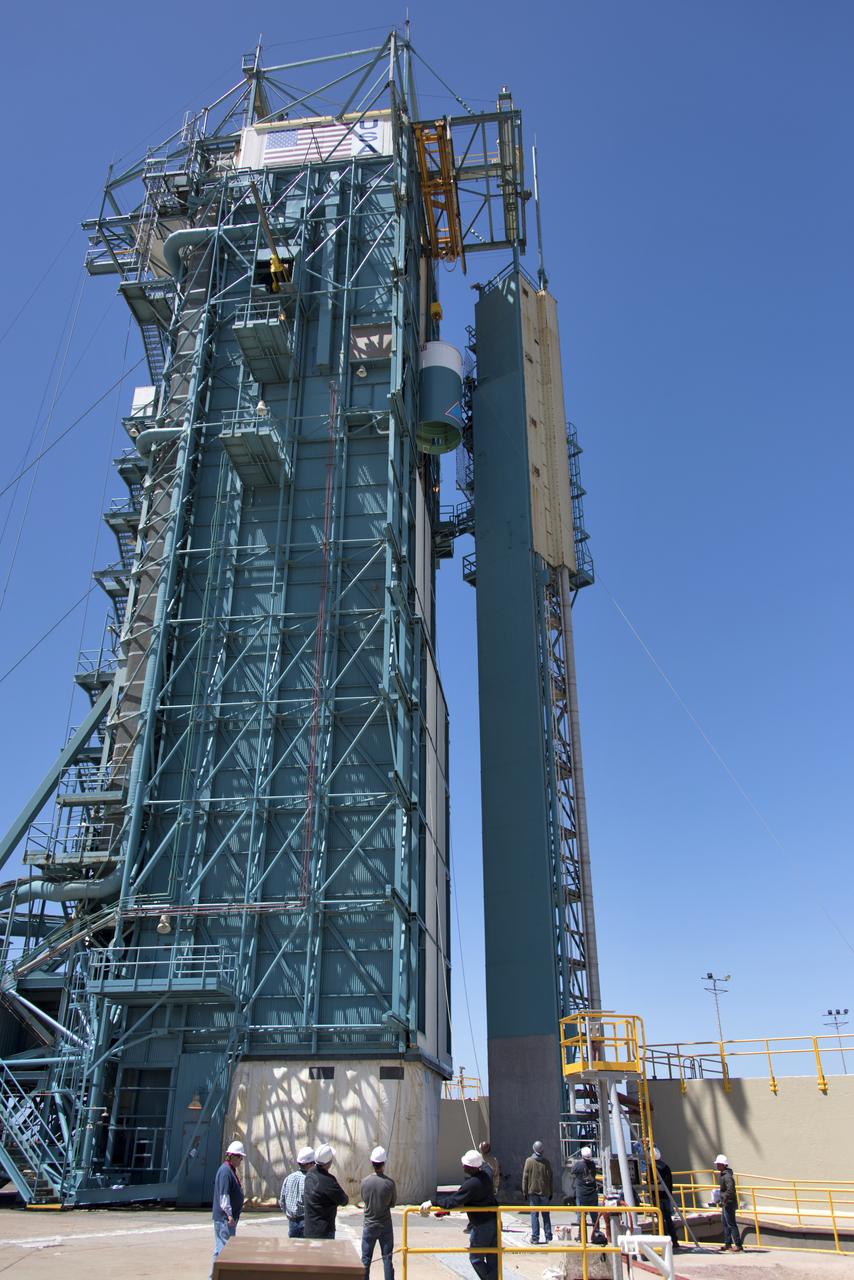
The United Launch Alliance Delta II second stage is lifted high up at the Vertical Integration Facility at Space Launch Complex 2 on June 12, 2018, at Vandenberg Air Force Base in California. The second stage will be attached to the top of the booster, or first stage of the rocket. NASA's Ice, Cloud and land Elevation Satellite-2 (ICESat-2) will launch on the final Delta II rocket. ICESat-2 will measure the height of a changing Earth, one laser pulse at a time, 10,000 laser pulses a second. The satellite will carry a single instrument, the Advanced Topographic Laser Altimeter System. ICESat-2 will help scientists investigate why, and how much our planet's frozen and icy areas, called the cryosphere, is changing in a warming climate.

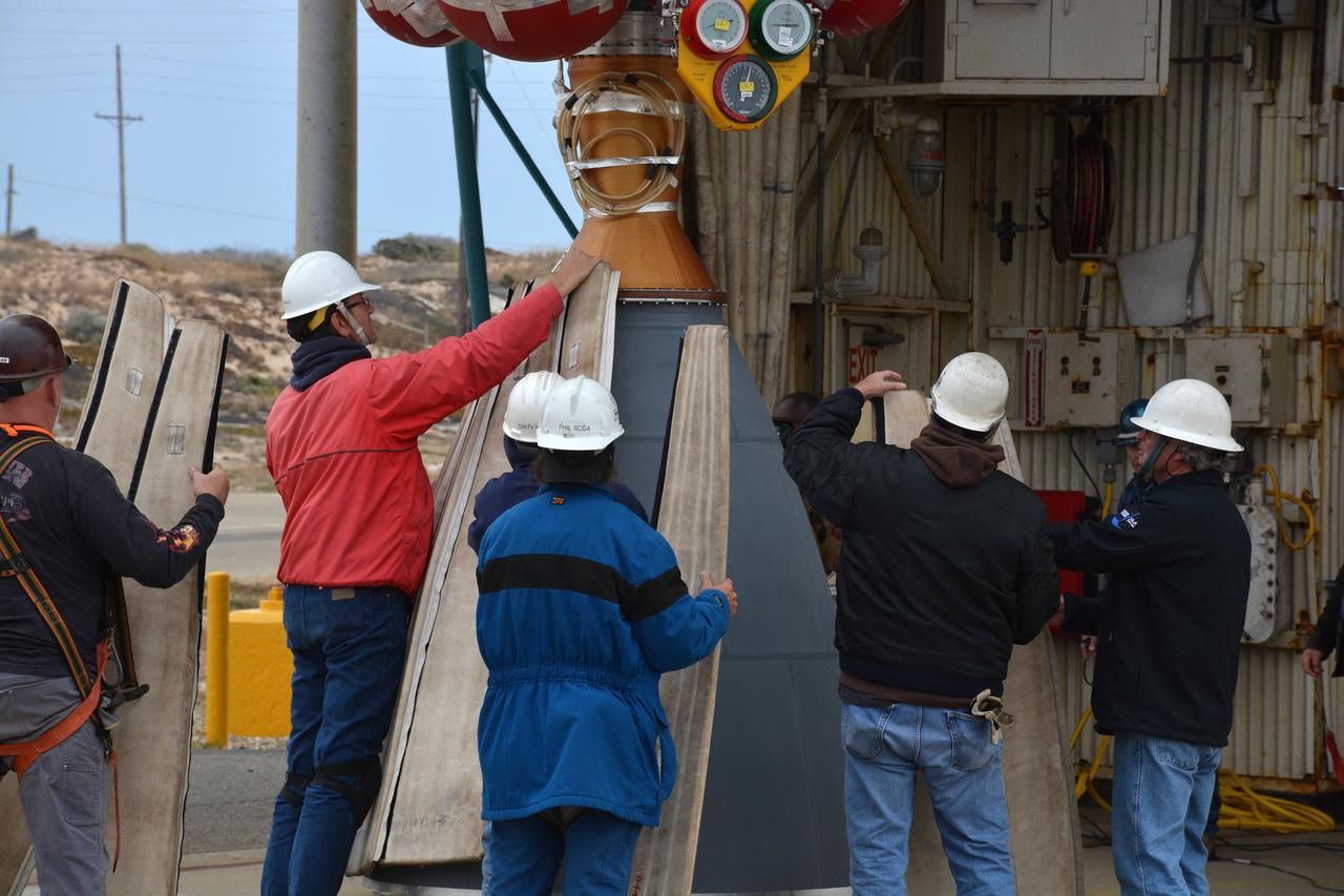
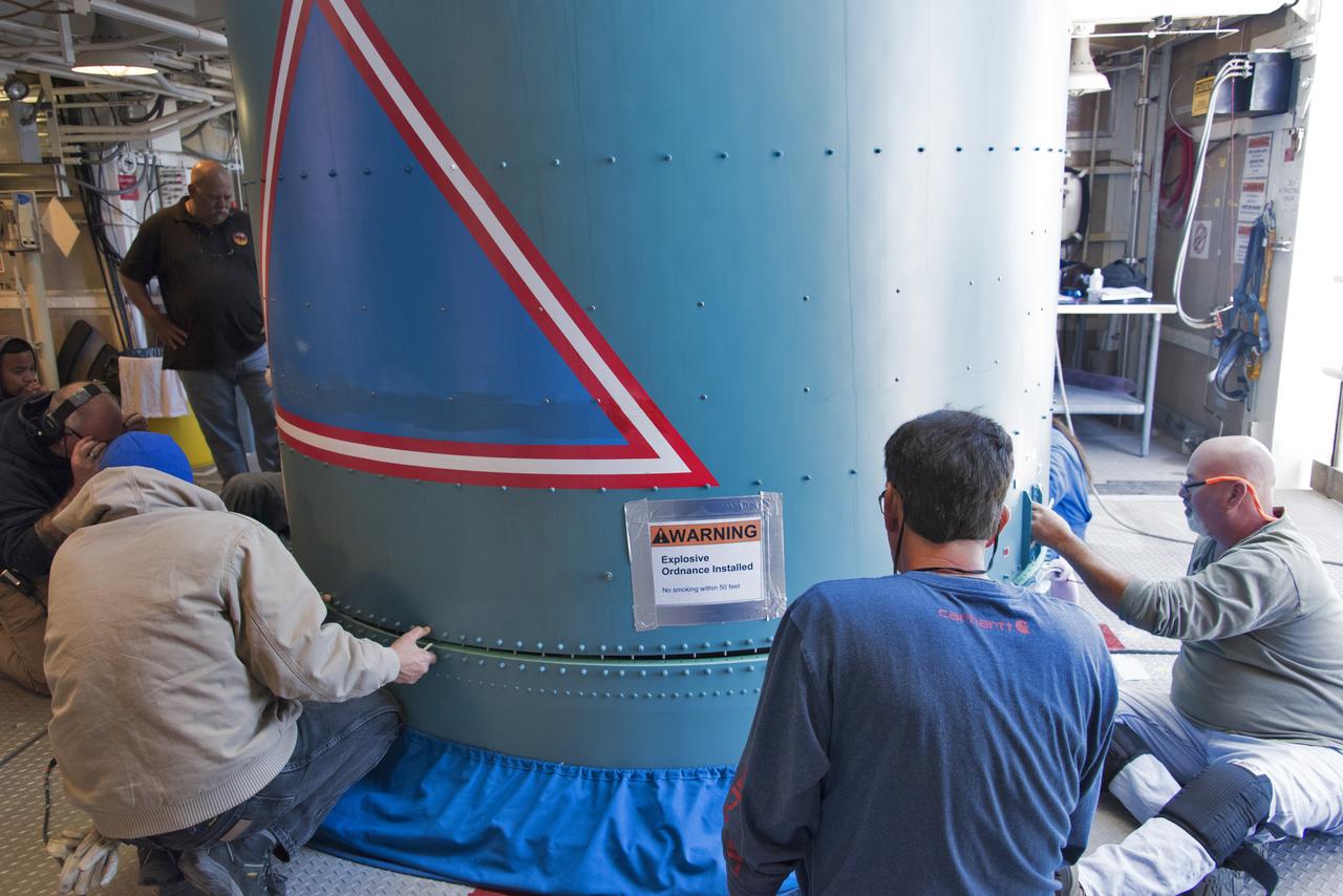
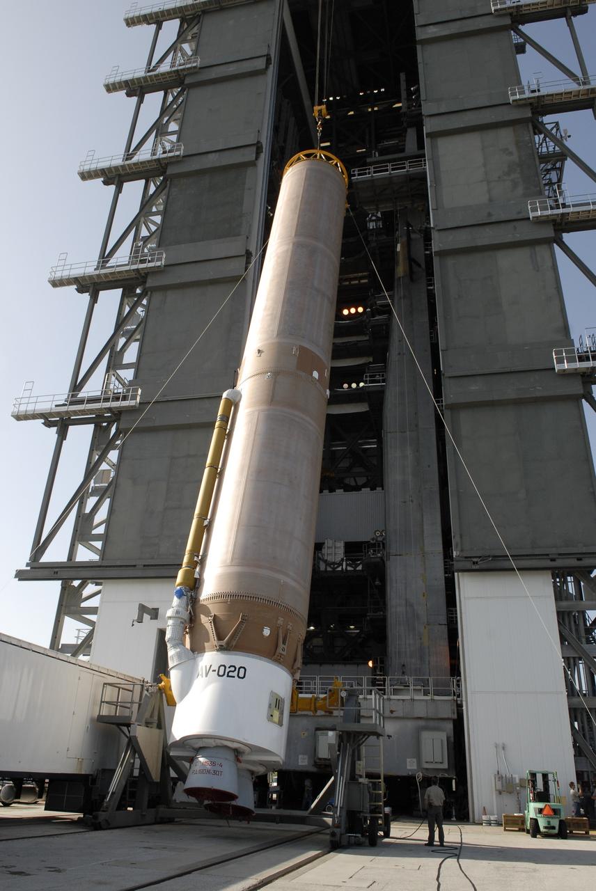
The solid rocket motor for mating to the United Launch Alliance Delta II launch vehicle is lifted up at the Vertical Integration Facility (VIF) at Space Launch Complex 2 on June 14, 2018, at Vandenberg Air Force Base in California. The solid rocket motor will be attached to the rocket. NASA's Ice, Cloud and land Elevation Satellite-2 (ICESat-2) will launch on the final Delta II rocket. ICESat-2 will measure the height of a changing Earth, one laser pulse at a time, 10,000 laser pulses a second. The satellite will carry a single instrument, the Advanced Topographic Laser Altimeter System. ICESat-2 will help scientists investigate why, and how much our planet's frozen and icy areas, called the cryosphere, is changing in a warming climate.
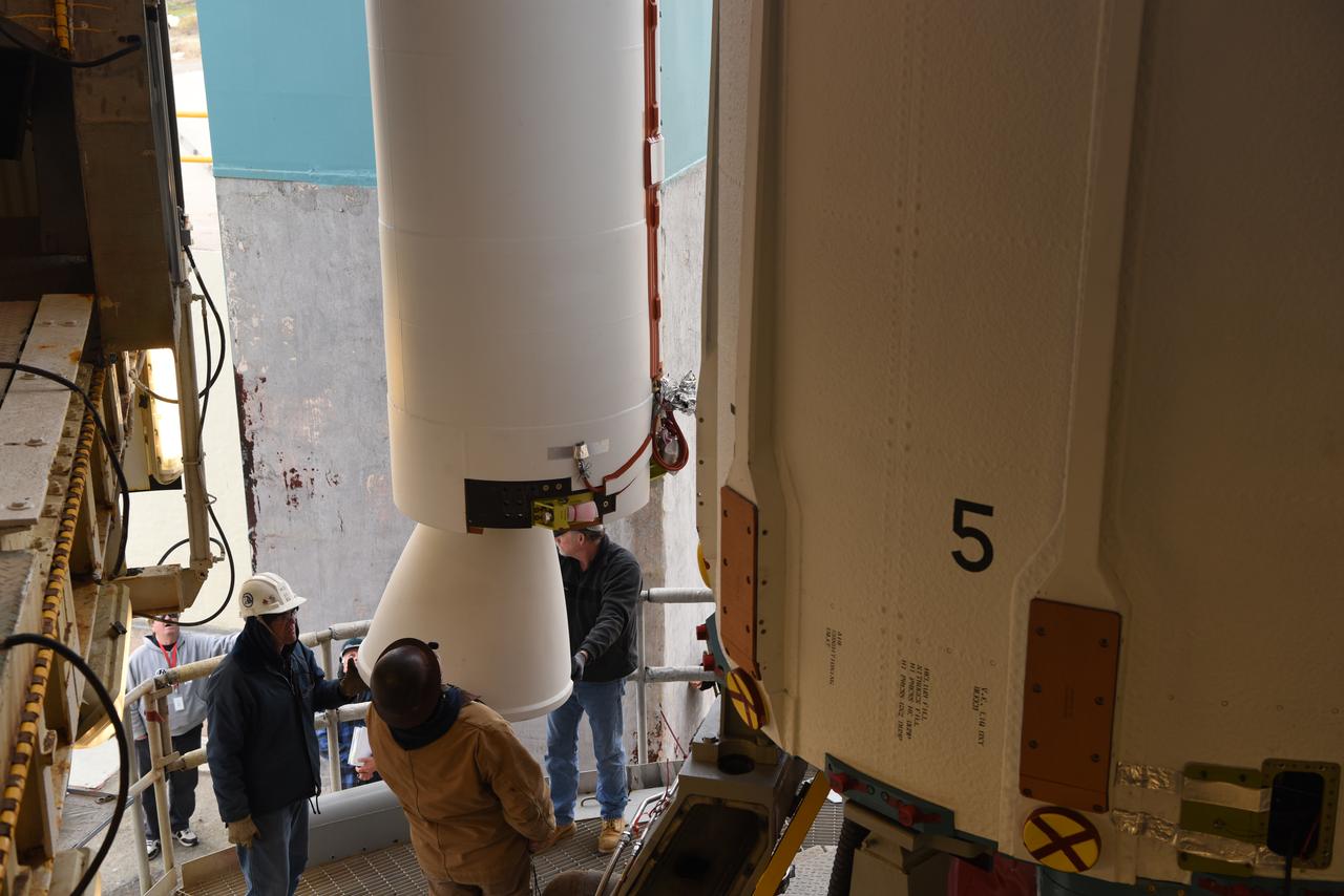
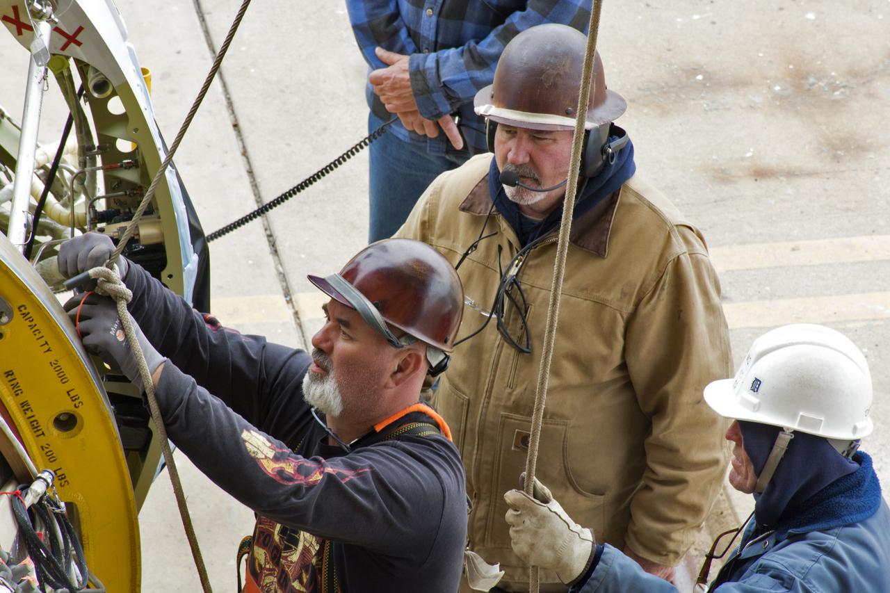
United Launch Alliance (ULA) technicians assist as the solid rocket motor is lifted up and moved toward the Delta II launch vehicle in the Vertical Integration Facility (VIF) at Space Launch Complex 2 on June 14, 2018, at Vandenberg Air Force Base in California. The solid rocket motor will be attached to the rocket. NASA's Ice, Cloud and land Elevation Satellite-2 (ICESat-2) will launch on the final ULA Delta II rocket. ICESat-2 will measure the height of a changing Earth, one laser pulse at a time, 10,000 laser pulses a second. The satellite will carry a single instrument, the Advanced Topographic Laser Altimeter System. ICESat-2 will help scientists investigate why, and how much our planet's frozen and icy areas, called the cryosphere, is changing in a warming climate.
The solid rocket motor for mating to the United Launch Alliance Delta II launch vehicle is lifted up at the Vertical Integration Facility (VIF) at Space Launch Complex 2 on June 14, 2018, at Vandenberg Air Force Base in California. The solid rocket motor will be attached to the rocket. NASA's Ice, Cloud and land Elevation Satellite-2 (ICESat-2) will launch on the final Delta II rocket. ICESat-2 will measure the height of a changing Earth, one laser pulse at a time, 10,000 laser pulses a second. The satellite will carry a single instrument, the Advanced Topographic Laser Altimeter System. ICESat-2 will help scientists investigate why, and how much our planet's frozen and icy areas, called the cryosphere, is changing in a warming climate.
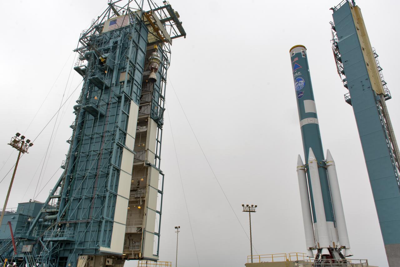
The second stage of the United Launch Alliance Delta II rocket is lifted high up at the Vertical Integration Facility, at left, at Space Launch Complex 2 on June 21, 2018, at Vandenberg Air Force Base in California. The second stage will be attached to the top of the booster, or first stage of the rocket, which is being moved out of the Mobile Service Tower, at right. NASA's Ice, Cloud and land Elevation Satellite-2 (ICESat-2) will launch on the final Delta II rocket. ICESat-2 will measure the height of a changing Earth, one laser pulse at a time, 10,000 laser pulses a second. The satellite will carry a single instrument, the Advanced Topographic Laser Altimeter System. ICESat-2 will help scientists investigate why, and how much our planet's frozen and icy areas, called the cryosphere, is changing in a warming climate.
The United Launch Alliance Delta II interstage is lifted up at the Vertical Integration Facility at Space Launch Complex 2 on June 12, 2018, at Vandenberg Air Force Base in California. The interstage will be moved in and mated to the top of the booster, or first stage of the rocket. NASA's Ice, Cloud and land Elevation Satellite-2 (ICESat-2) will launch on the final Delta II rocket. ICESat-2 will measure the height of a changing Earth, one laser pulse at a time, 10,000 laser pulses a second. The satellite will carry a single instrument, the Advanced Topographic Laser Altimeter System. ICESat-2 will help scientists investigate why, and how much our planet's frozen and icy areas, called the cryosphere, is changing in a warming climate.
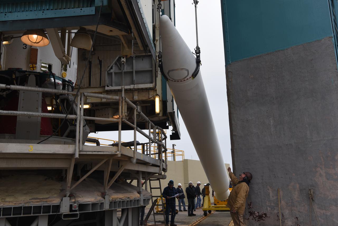
The solid rocket motor for mating to the United Launch Alliance Delta II launch vehicle arrives at the Vertical Integration Facility (VIF) at Space Launch Complex 2 on June 14, 2018, at Vandenberg Air Force Base in California. The solid rocket motor will be lifted up and attached to the rocket. NASA's Ice, Cloud and land Elevation Satellite-2 (ICESat-2) will launch on the final Delta II rocket. ICESat-2 will measure the height of a changing Earth, one laser pulse at a time, 10,000 laser pulses a second. The satellite will carry a single instrument, the Advanced Topographic Laser Altimeter System. ICESat-2 will help scientists investigate why, and how much our planet's frozen and icy areas, called the cryosphere, is changing in a warming climate.
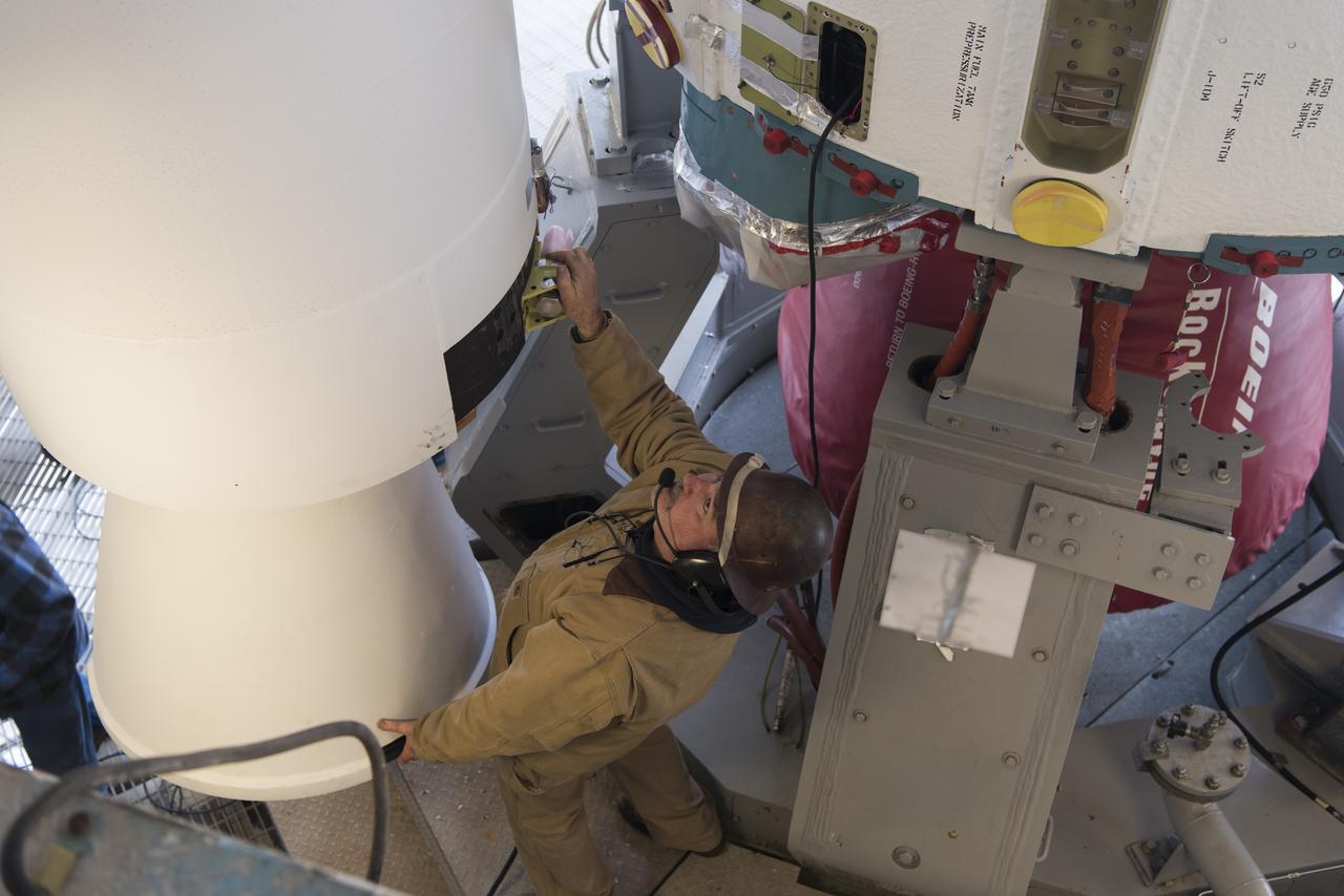
United Launch Alliance (ULA) technicians assist as the solid rocket motor is moved toward the Delta II launch vehicle in the Vertical Integration Facility (VIF) at Space Launch Complex 2 on June 14, 2018, at Vandenberg Air Force Base in California. The solid rocket motor will be attached to the rocket. NASA's Ice, Cloud and land Elevation Satellite-2 (ICESat-2) will launch on the final ULA Delta II rocket. ICESat-2 will measure the height of a changing Earth, one laser pulse at a time, 10,000 laser pulses a second. The satellite will carry a single instrument, the Advanced Topographic Laser Altimeter System. ICESat-2 will help scientists investigate why, and how much our planet's frozen and icy areas, called the cryosphere, is changing in a warming climate.
The United Launch Alliance Delta II interstage is lifted high up at the Vertical Integration Facility at Space Launch Complex 2 on June 12, 2018, at Vandenberg Air Force Base in California. The interstage will be moved in and mated to the top of the booster, or first stage of the rocket. NASA's Ice, Cloud and land Elevation Satellite-2 (ICESat-2) will launch on the final Delta II rocket. ICESat-2 will measure the height of a changing Earth, one laser pulse at a time, 10,000 laser pulses a second. The satellite will carry a single instrument, the Advanced Topographic Laser Altimeter System. ICESat-2 will help scientists investigate why, and how much our planet's frozen and icy areas, called the cryosphere, is changing in a warming climate.
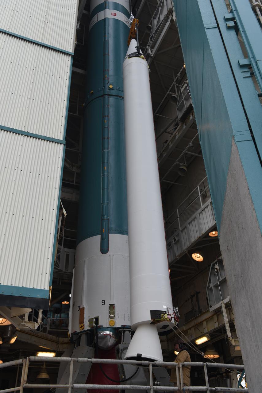
The solid rocket motor for mating to the United Launch Alliance Delta II launch vehicle is lifted up at the Vertical Integration Facility (VIF) at Space Launch Complex 2 on June 14, 2018, at Vandenberg Air Force Base in California. The solid rocket motor will be attached to the rocket. NASA's Ice, Cloud and land Elevation Satellite-2 (ICESat-2) will launch on the final Delta II rocket. ICESat-2 will measure the height of a changing Earth, one laser pulse at a time, 10,000 laser pulses a second. The satellite will carry a single instrument, the Advanced Topographic Laser Altimeter System. ICESat-2 will help scientists investigate why, and how much our planet's frozen and icy areas, called the cryosphere, is changing in a warming climate.
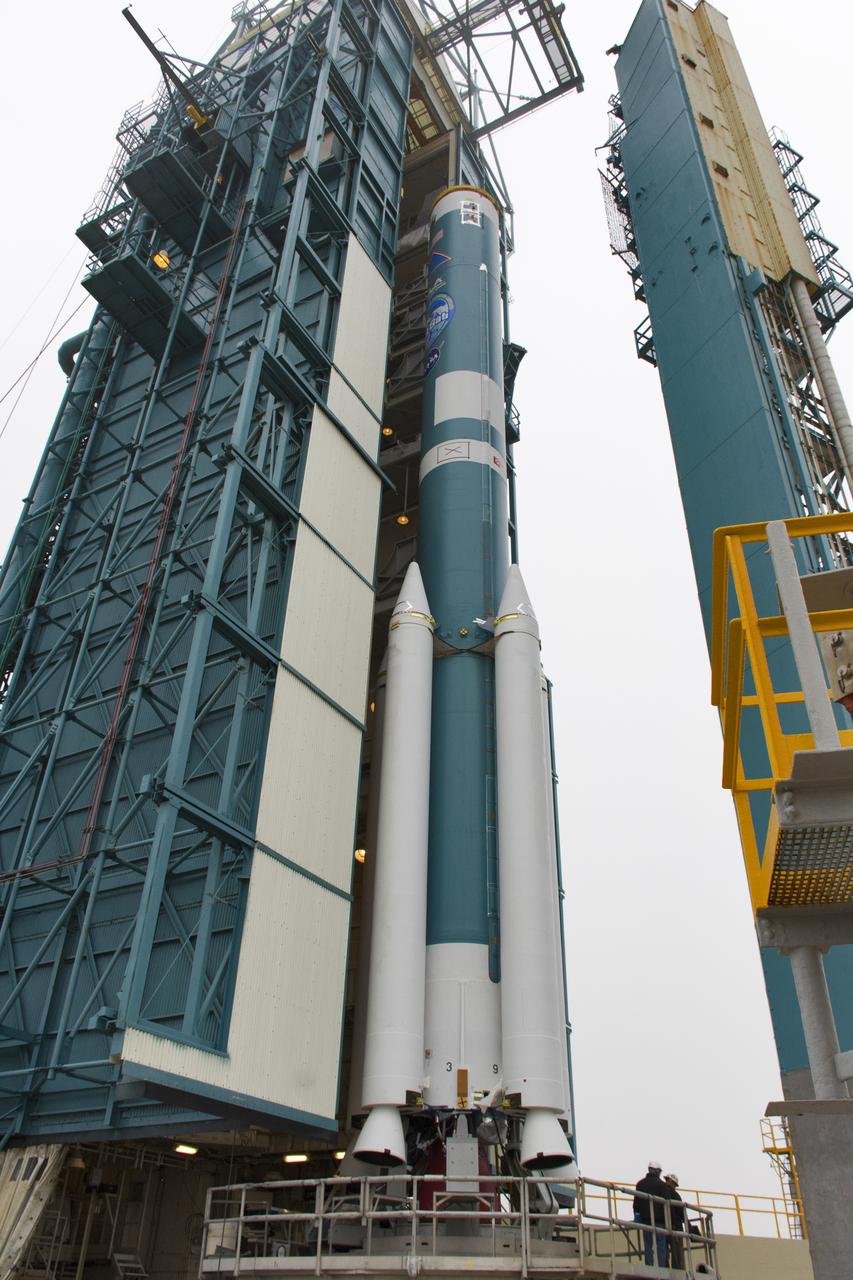
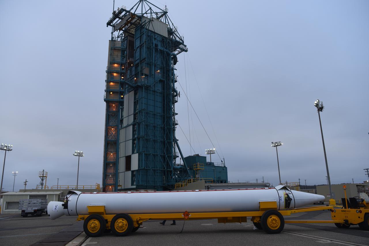
The United Launch Alliance Delta II booster, or first stage, with the interstage attached on top is moved out of the Vertical Integration Facility (VIF) at Space Launch Complex 2 on June 21, 2018, at Vandenberg Air Force Base in California. The second stage will be lifted up at the VIF. NASA's Ice, Cloud and land Elevation Satellite-2 (ICESat-2) will launch on the final Delta II rocket. ICESat-2 will measure the height of a changing Earth, one laser pulse at a time, 10,000 laser pulses a second. The satellite will carry a single instrument, the Advanced Topographic Laser Altimeter System. ICESat-2 will help scientists investigate why, and how much our planet's frozen and icy areas, called the cryosphere, is changing in a warming climate.
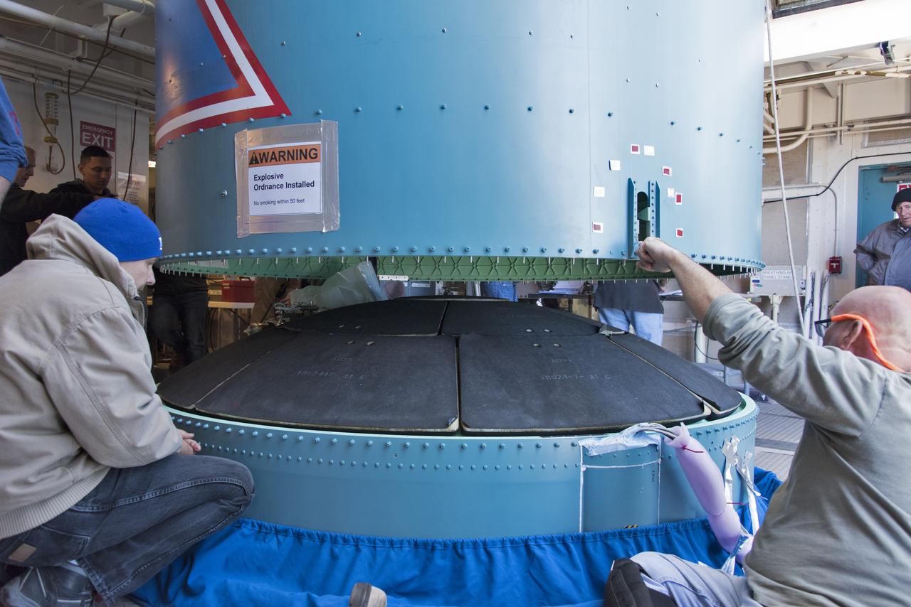
Inside the Vertical Integration Facility at Space Launch Complex 2 at Vandenberg Air Force Base in California, United Launch Alliance (ULA) workers assist as the Delta II interstage is lowered and mated to the booster, or first stage, on June 12, 2018. NASA's Ice, Cloud and land Elevation Satellite-2 (ICESat-2) will launch on the final Delta II rocket. ICESat-2 will measure the height of a changing Earth, one laser pulse at a time, 10,000 laser pulses a second. The satellite will carry a single instrument, the Advanced Topographic Laser Altimeter System. ICESat-2 will help scientists investigate why, and how much our planet's frozen and icy areas, called the cryosphere, is changing in a warming climate.
United Launch Alliance workers prepare the first stage of the Delta II second stage to be lifted up in the Vertical Processing Facility at Space Launch Complex 2 on June 21, 2018, at Vandenberg Air Force Base in California. The second stage will be attached to the top of the booster, or first stage, of the rocket. NASA's Ice, Cloud and land Elevation Satellite-2 (ICESat-2) will launch on the final Delta II rocket. ICESat-2 will measure the height of a changing Earth, one laser pulse at a time, 10,000 laser pulses a second. The satellite will carry a single instrument, the Advanced Topographic Laser Altimeter System. ICESat-2 will help scientists investigate why, and how much our planet's frozen and icy areas, called the cryosphere, is changing in a warming climate.
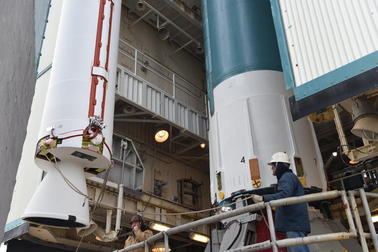
The solid rocket motor for mating to the United Launch Alliance Delta II launch vehicle is lifted up at the Vertical Integration Facility (VIF) at Space Launch Complex 2 on June 14, 2018, at Vandenberg Air Force Base in California. The solid rocket motor will be attached to the rocket. NASA's Ice, Cloud and land Elevation Satellite-2 (ICESat-2) will launch on the final Delta II rocket. ICESat-2 will measure the height of a changing Earth, one laser pulse at a time, 10,000 laser pulses a second. The satellite will carry a single instrument, the Advanced Topographic Laser Altimeter System. ICESat-2 will help scientists investigate why, and how much our planet's frozen and icy areas, called the cryosphere, is changing in a warming climate.
Inside the Vertical Integration Facility at Space Launch Complex 2 at Vandenberg Air Force Base in California, United Launch Alliance (ULA) workers help secure the Delta II interstage to the top of the booster, or first stage, on June 12, 2018. NASA's Ice, Cloud and land Elevation Satellite-2 (ICESat-2) will launch on the final Delta II rocket. ICESat-2 will measure the height of a changing Earth, one laser pulse at a time, 10,000 laser pulses a second. The satellite will carry a single instrument, the Advanced Topographic Laser Altimeter System. ICESat-2 will help scientists investigate why, and how much our planet's frozen and icy areas, called the cryosphere, is changing in a warming climate.
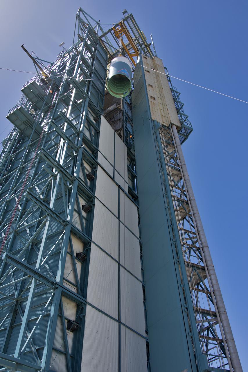
The United Launch Alliance Delta II interstage is lifted high up at the Vertical Integration Facility at Space Launch Complex 2 on June 12, 2018, at Vandenberg Air Force Base in California. The interstage will be moved in and mated to the top of the booster, or first stage of the rocket. NASA's Ice, Cloud and land Elevation Satellite-2 (ICESat-2) will launch on the final Delta II rocket. ICESat-2 will measure the height of a changing Earth, one laser pulse at a time, 10,000 laser pulses a second. The satellite will carry a single instrument, the Advanced Topographic Laser Altimeter System. ICESat-2 will help scientists investigate why, and how much our planet's frozen and icy areas, called the cryosphere, is changing in a warming climate.
United Launch Alliance workers prepare the first stage of the Delta II second stage to be lifted up in the Vertical Processing Facility at Space Launch Complex 2 on June 21, 2018, at Vandenberg Air Force Base in California. The second stage will be attached to the top of the booster, or first stage, of the rocket. NASA's Ice, Cloud and land Elevation Satellite-2 (ICESat-2) will launch on the final Delta II rocket. ICESat-2 will measure the height of a changing Earth, one laser pulse at a time, 10,000 laser pulses a second. The satellite will carry a single instrument, the Advanced Topographic Laser Altimeter System. ICESat-2 will help scientists investigate why, and how much our planet's frozen and icy areas, called the cryosphere, is changing in a warming climate.
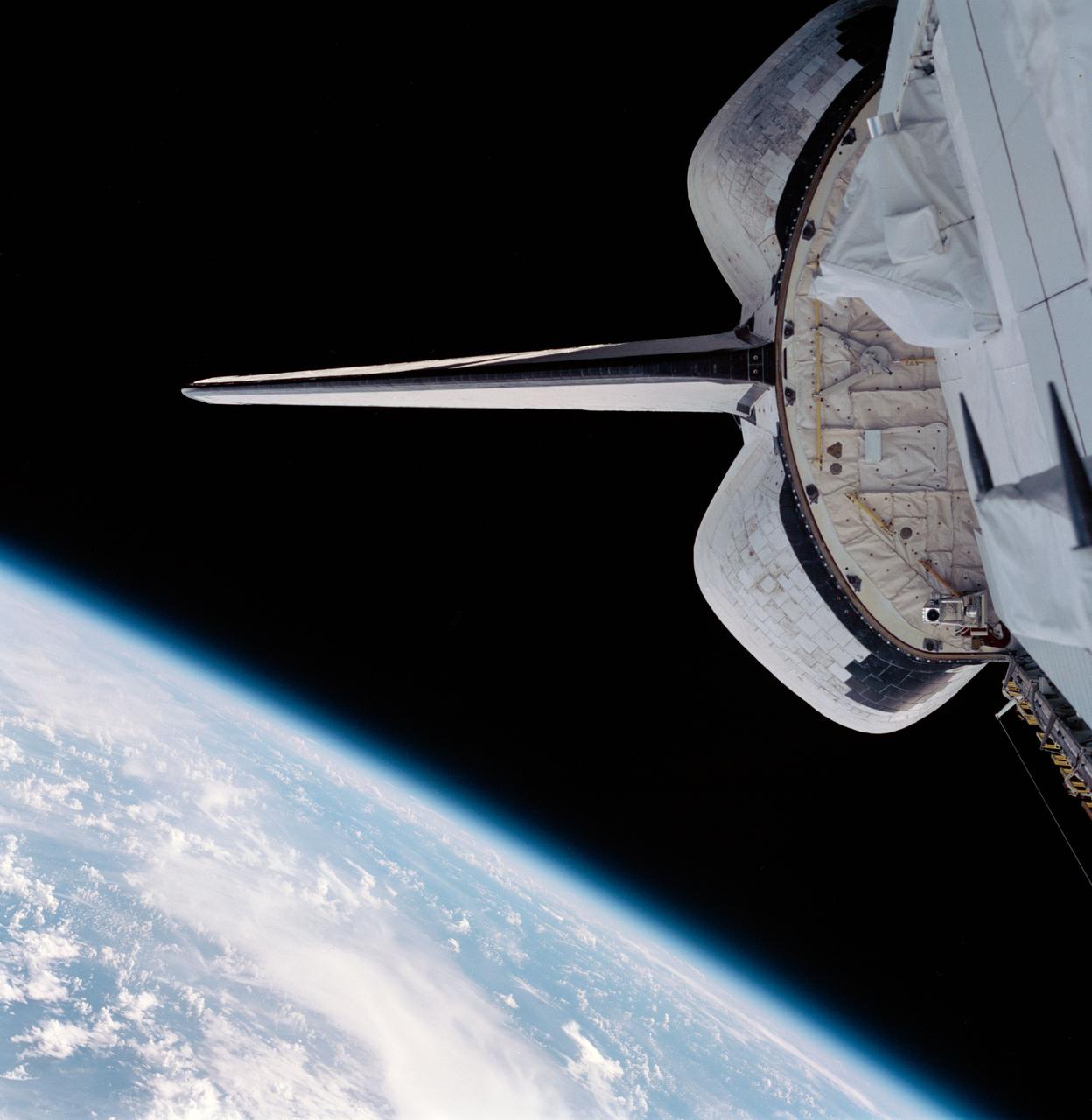
STS099-703-082 (11-22 February 2000) --- Part of the Space Shuttle Endeavour's aft cargo bay, its vertical stabilizer and orbital maneuvering system (OMS) pods are seen in this 70mm frame. Part of Earth's horizon, with an expanse of heavy cloud cover over land and water, is at bottom of frame.
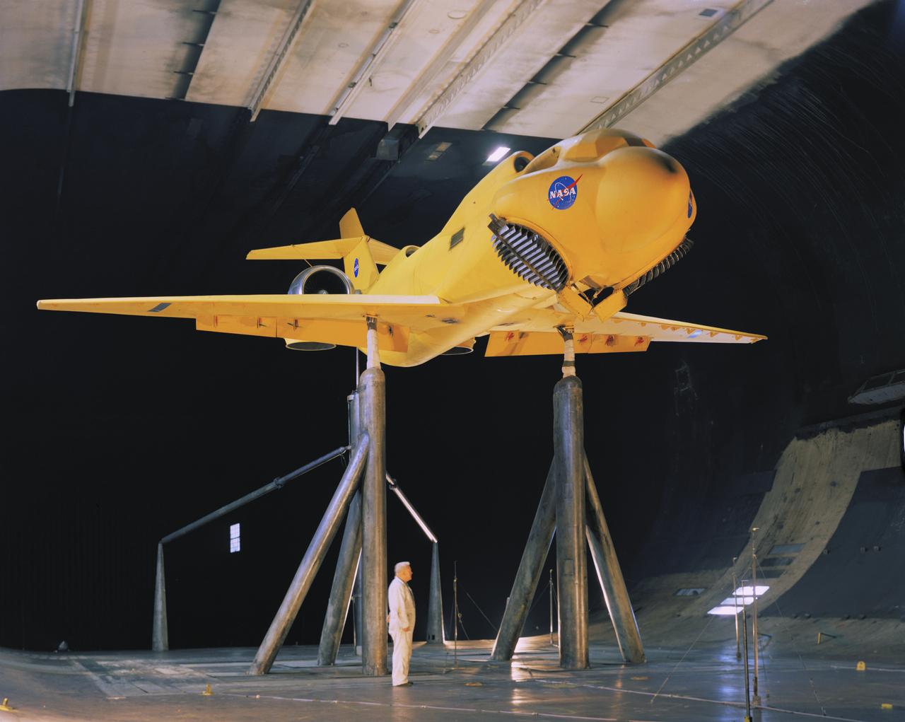
3/4 front view of McDonnell-Douglas Large-Scale lift fan, vertical and/or short take-off and landing (V/STOL), transport model. Francis Malerick in photograph. The McDonnell Douglas DC-9 (initially known as the Douglas DC-9) is a twin-engine, single-aisle jet airliner.

Vertol VZ-2 (Model 76): Arriving at Langley from Edwards Air Force Base, California, this Vertol VZ-2 underwent almost a year and a half of flight research before going back to the manufacturer for rework. The VZ-2 was used to investigate Vertical Take-Off and Landing (VTOL).
Collins Aerodyne vertical take-off and landing (VTOL) aircraft investigations. Ground plane support system. 3/4 front view. Dave Koening (from Collins Aerodyne) in photo. Mounted on variable height struts, ground board system, zero degree angle of attack. 01/11/1960
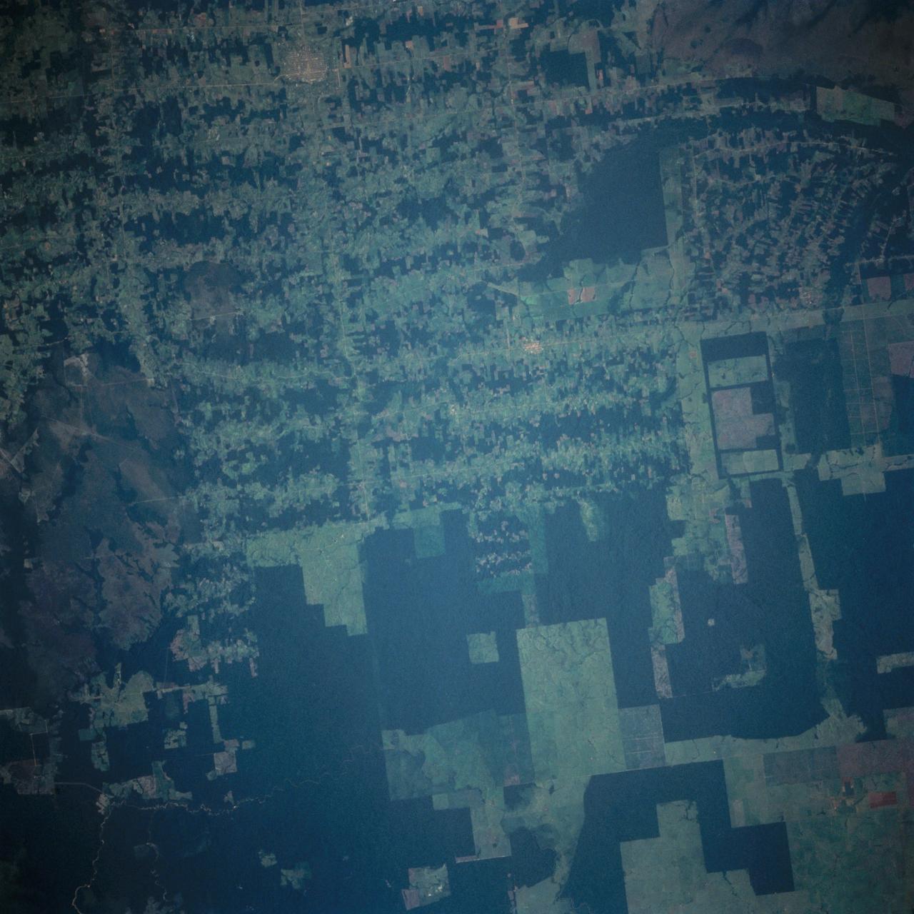
This near vertical photograph illustrates the differences in agricultural land patterns typically seen in many parts of southwestern Brazil, near the Bolivian border. The larger rectangular field patterns reflect a mature, fully developed agricultural environment. The smaller areas are less well defined and indicate new agricultural development.
3/4 front right side only with Tim Wills on right and Charles Greco, mechanic. Large flaps on Variable height struts. XC-142 was a tri-service tiltwing experimental aircraft designed to investigate the operational suitability of vertical/short takeoff and landing (V/STOL) transports.
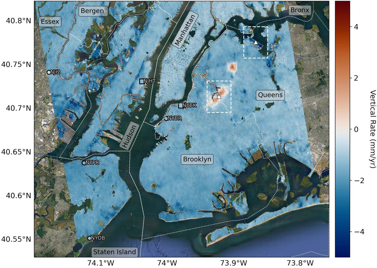
Researchers from NASA's Jet Propulsion Laboratory in Southern California and Rutgers University in New Jersey produced this map in their analysis of upward and downward vertical land motion – also known as uplift and subsidence – across the New York City metropolitan area from 2016 to 2023. Most of the study region was found to be gradually subsiding (indicated here in blue), while isolated locations of uplift (in red) were also observed. The white dotted lines indicate county/borough borders. The researchers found that on average the metropolitan area subsided by about 0.06 inches (1.6 millimeters) per year – about the same amount that a toenail grows in a month. They mapped the motion in detail and pinpointed neighborhoods and landmarks that were subsiding more rapidly than the average. Causes for the observed motion include natural geologic adjustments that have been unfolding since the most recent ice age, as well as human land-use practices such as the construction of landfills, which make the ground looser and more compressible beneath buildings. A few locations in Queens and Brooklyn were observed to rise due to activities that may include pollution remediation efforts and groundwater injection. To create this map, the researchers employed a remote sensing technique called interferometric synthetic aperture radar (InSAR), which combines two or more three-dimensional observations of the same region to reveal surface motion down to fractions of inches. They used the radars on the ESA (European Space Agency) Sentinel-1 satellites, along with advanced data processing methods. https://photojournal.jpl.nasa.gov/catalog/PIA25527

41G-121-099 (5-13 Oct. 1984) --- Hurricane Josephine was photographed with a medium format camera aimed through the space shuttle Challenger's aft flight deck windows during NASA's 41-G mission. The hurricane's eye can be seen below the orbiter's vertical stabilizer. The large storm off the Florida coast did not prevent the spacecraft with its record of seven crew members aboard from landing safely at the KSC landing facility. Photo credit: NASA
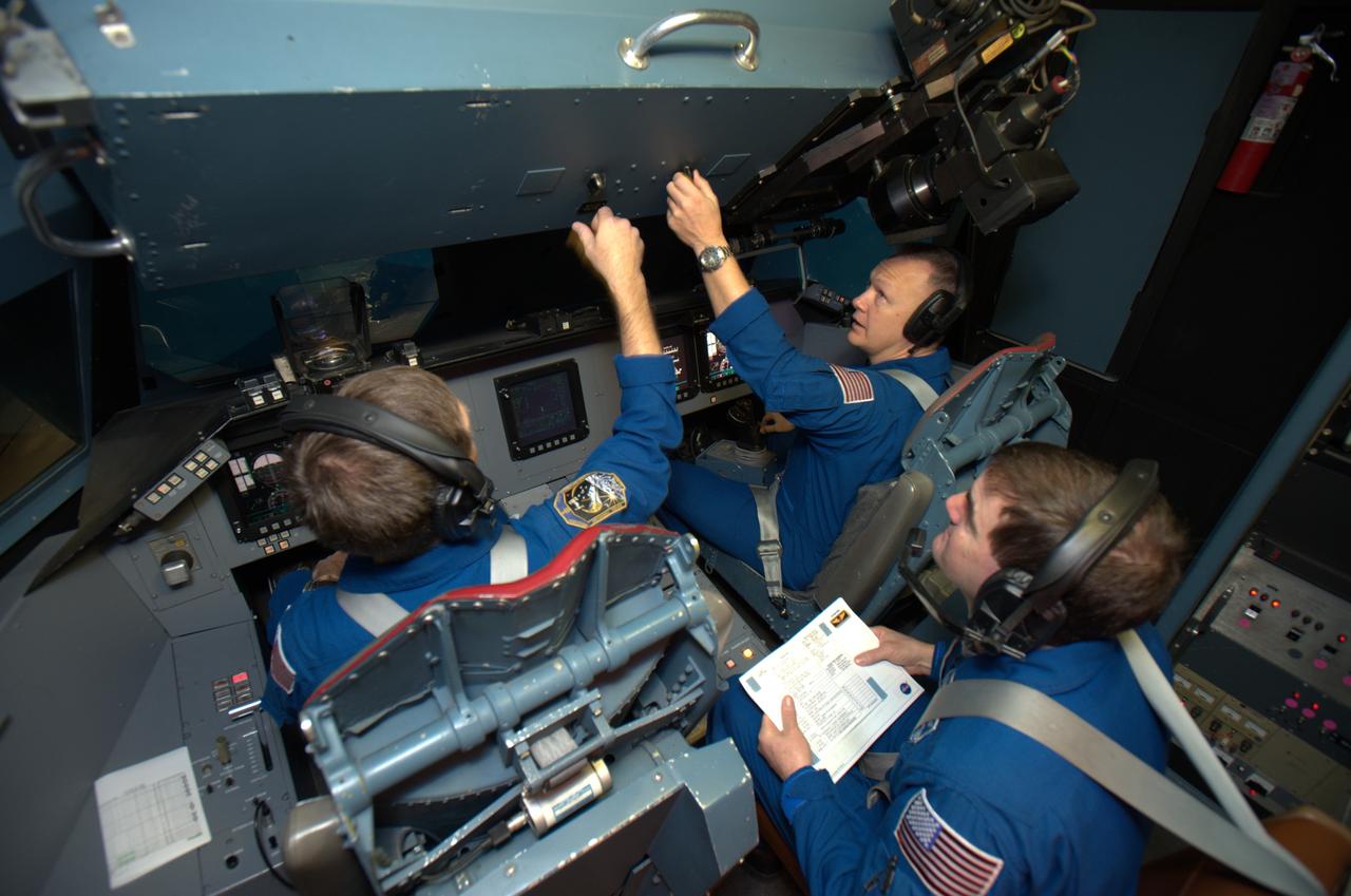
STS-135 astronaut training in the Vertical Motion Simulator, Ames Research Center, Moffett Field, CA. In this overhead view are Chris Ferguson commander on right, Doug Hurley, pilot on left and Rex Walheim, mission specialist, center back are in VMS S-cab cockpit for simulated landing practice under a variety of landing sites and conditions.
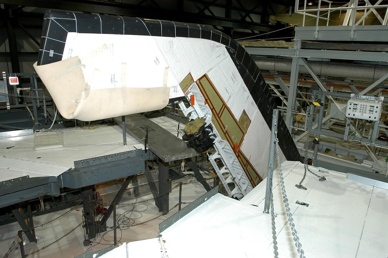
KENNEDY SPACE CENTER, FLA. -- A Rudder Speed Brake Actuator is being removed from the orbiter Atlantis for shipment to the vendor for inspection. An actuator is a motor that moves the tail rudder back and forth to help steer it during landing and brake its speed. The vertical tail consists of a structural fin surface made of aluminum, the Rudder Speed Brake surface, a tip and a lower trailing edge. The rudder splits into two halves to serve as a speed brake. The vertical tail and Rudder Speed Brake are covered with a reusable thermal protection system. Atlantis is undergoing maintenance and inspection in the Orbiter Processing Facility for a future mission.
KENNEDY SPACE CENTER, FLA. -- Workers ensure the safe removal of a Rudder Speed Brake Actuator from the orbiter Atlantis. This and three other actuators are being shipped to the vendor for inspection. An actuator is a motor that moves the tail rudder back and forth to help steer it during landing and brake its speed. The vertical tail consists of a structural fin surface made of aluminum, the Rudder Speed Brake surface, a tip and a lower trailing edge. The rudder splits into two halves to serve as a speed brake. The vertical tail and Rudder Speed Brake are covered with a reusable thermal protection system. Atlantis is undergoing maintenance and inspection in the Orbiter Processing Facility for a future mission.
CAPE CANAVERAL, Fla. –– When the Atlas V first stage is raised to vertical, it will be lifted into the Vertical Integration Facility on Cape Canaveral Air Force Station's Launch Complex 41. The Atlas V/Centaur is the launch vehicle for the Lunar Reconnaissance Orbiter, or LRO. The orbiter will carry seven instruments to provide scientists with detailed maps of the lunar surface and enhance our understanding of the moon's topography, lighting conditions, mineralogical composition and natural resources. Information gleaned from LRO will be used to select safe landing sites, determine locations for future lunar outposts and help mitigate radiation dangers to astronauts. Launch of LRO is targeted no earlier than June 2. Photo credit: NASA/Kim Shiflett
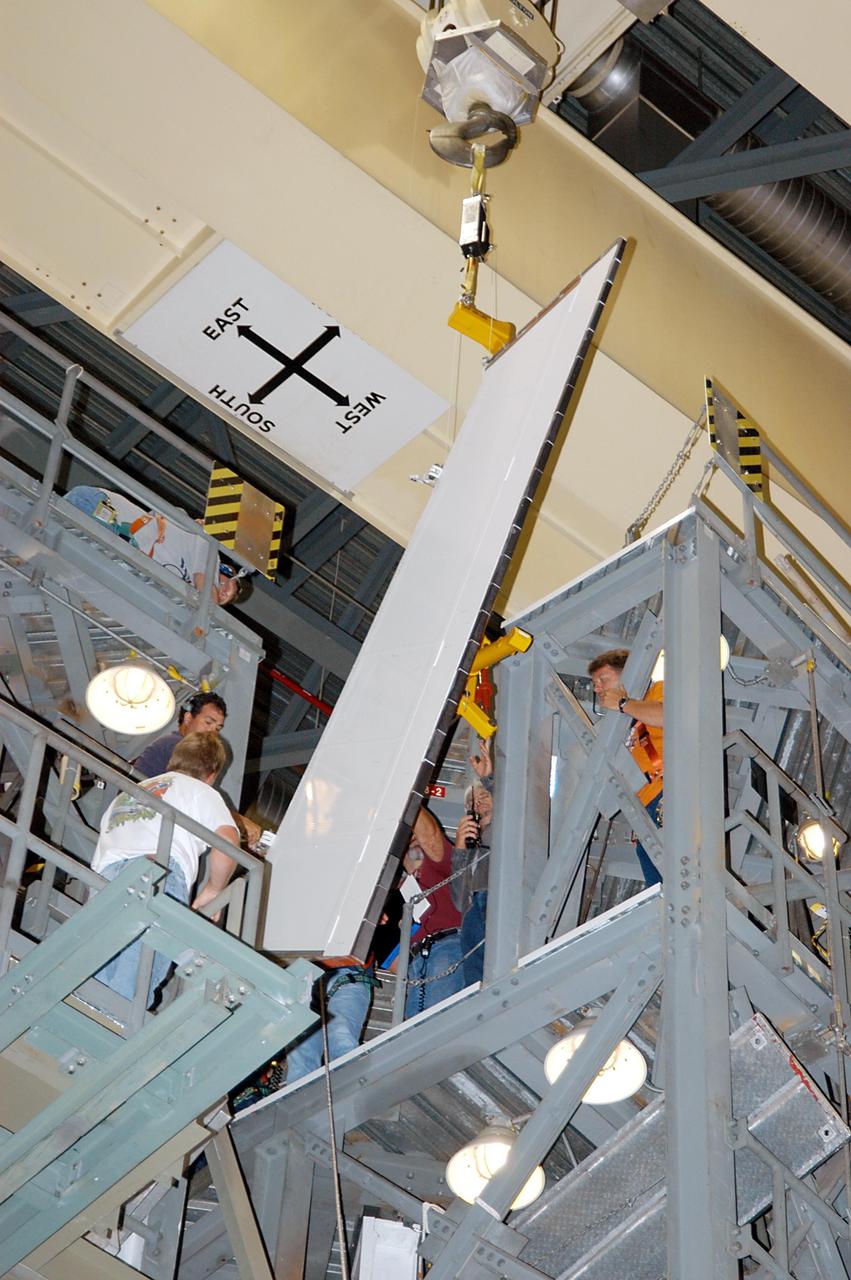
KENNEDY SPACE CENTER, FLA. -- In the Orbiter Processing Facility, the Rudder Speed Brake panel from orbiter Atlantis is lifted clear after being removed. The Rudder Speed Brake is being removed for inspection and maintenance prior to Return to Flight. The vertical tail consists of a structural fin surface made of aluminum, the Rudder Speed Brake surface, a tip and a lower trailing edge. The rudder splits into two halves to serve as a speed brake. The vertical tail and Rudder Speed Brake are covered with a reusable thermal protection system. The Rudder Speed Brake is used to guide and slow the Shuttle as it comes in for a landing.

Vice President Mike Pence, at left, tours the Blue Origin Manufacturing Facility near NASA's Kennedy Space Center in Florida, Feb. 20, 2018, with the company's CEO Robert Smith. Vice President Pence viewed the flown New Shepard Booster and Crew Capsule. The booster was the first launch vehicle with a successful vertical takeoff and vertical landing to demonstrate reusability. During his visit, Pence will chair a meeting of the National Space Council on Feb. 21, 2018 in the high bay of NASA Kennedy Space Center's Space Station Processing Facility. The council's role is to advise the president regarding national space policy and strategy, and review the nation's long-range goals for space activities.
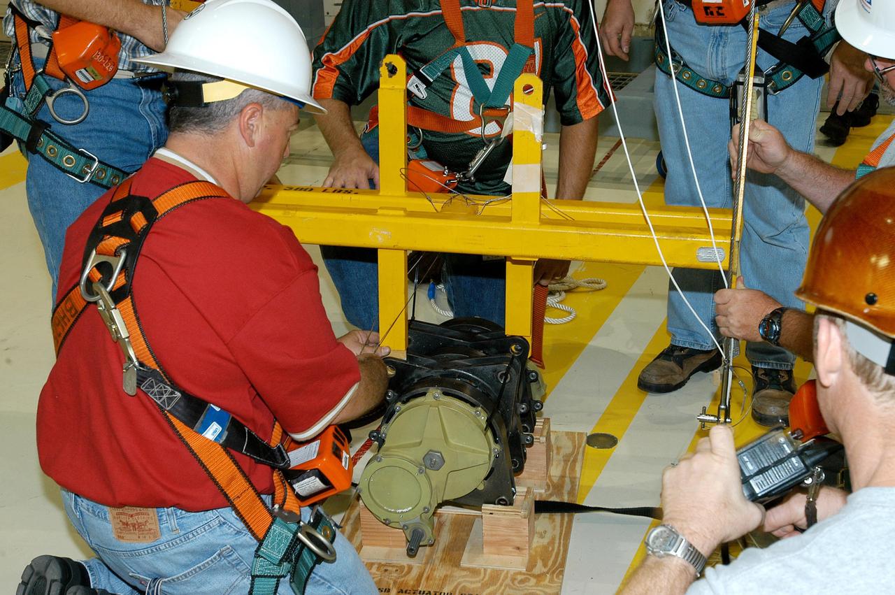
KENNEDY SPACE CENTER, FLA. -- A Rudder Speed Brake Actuator from the orbiter Atlantis is set on a stand on the floor of the Orbiter Processing Facility. This and three other actuators are being shipped to the vendor for inspection. An actuator is a motor that moves the tail rudder back and forth to help steer it during landing and brake its speed. The vertical tail consists of a structural fin surface made of aluminum, the Rudder Speed Brake surface, a tip and a lower trailing edge. The rudder splits into two halves to serve as a speed brake. The vertical tail and Rudder Speed Brake are covered with a reusable thermal protection system. Atlantis is undergoing maintenance and inspection for a future mission.
KENNEDY SPACE CENTER, FLA. -- Workers attach a crane to one of the Rudder Speed Brake Actuators that are being removed from the orbiter Atlantis for shipment to the vendor for inspection. An actuator is a motor that moves the tail rudder back and forth to help steer it during landing and brake its speed. The vertical tail consists of a structural fin surface made of aluminum, the Rudder Speed Brake surface, a tip and a lower trailing edge. The rudder splits into two halves to serve as a speed brake. The vertical tail and Rudder Speed Brake are covered with a reusable thermal protection system. Atlantis is undergoing maintenance and inspection in the Orbiter Processing Facility for a future mission.
KENNEDY SPACE CENTER, FLA. -- A Rudder Speed Brake Actuator is being removed from the orbiter Atlantis for shipment to the vendor for inspection. An actuator is a motor that moves the tail rudder back and forth to help steer it during landing and brake its speed. The vertical tail consists of a structural fin surface made of aluminum, the Rudder Speed Brake surface, a tip and a lower trailing edge. The rudder splits into two halves to serve as a speed brake. The vertical tail and Rudder Speed Brake are covered with a reusable thermal protection system. Atlantis is undergoing maintenance and inspection in the Orbiter Processing Facility for a future mission.
KENNEDY SPACE CENTER, FLA. -- Workers attach a crane to one of the Rudder Speed Brake Actuators that are being removed from the orbiter Atlantis for shipment to the vendor for inspection. An actuator is a motor that moves the tail rudder back and forth to help steer it during landing and brake its speed. The vertical tail consists of a structural fin surface made of aluminum, the Rudder Speed Brake surface, a tip and a lower trailing edge. The rudder splits into two halves to serve as a speed brake. The vertical tail and Rudder Speed Brake are covered with a reusable thermal protection system. Atlantis is undergoing maintenance and inspection in the Orbiter Processing Facility for a future mission.
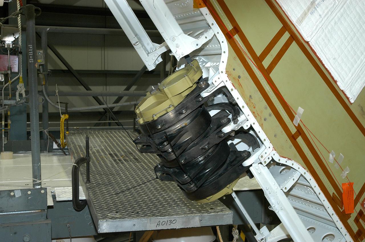
KENNEDY SPACE CENTER, FLA. -- This is a closeup of one of the Rudder Speed Brake Actuators that are being removed from the orbiter Atlantis for shipment to the vendor for inspection. An actuator is a motor that moves the tail rudder back and forth to help steer it during landing and brake its speed. The vertical tail consists of a structural fin surface made of aluminum, the Rudder Speed Brake surface, a tip and a lower trailing edge. The rudder splits into two halves to serve as a speed brake. The vertical tail and Rudder Speed Brake are covered with a reusable thermal protection system. Atlantis is undergoing maintenance and inspection in the Orbiter Processing Facility for a future mission.
KENNEDY SPACE CENTER, FLA. -- Workers ensure the safe removal of a Rudder Speed Brake Actuator from the orbiter Atlantis. This and three other actuators are being shipped to the vendor for inspection. An actuator is a motor that moves the tail rudder back and forth to help steer it during landing and brake its speed. The vertical tail consists of a structural fin surface made of aluminum, the Rudder Speed Brake surface, a tip and a lower trailing edge. The rudder splits into two halves to serve as a speed brake. The vertical tail and Rudder Speed Brake are covered with a reusable thermal protection system. Atlantis is undergoing maintenance and inspection in the Orbiter Processing Facility for a future mission.

This is a radar image of the Mississippi River Delta where the river enters into the Gulf of Mexico along the coast of Louisiana. This multi-frequency image demonstrates the capability of the radar to distinguish different types of wetlands surfaces in river deltas. This image was acquired by the Spaceborne Imaging Radar-C/X-Band Synthetic Aperture Radar (SIR-C/X-SAR) aboard the space shuttle Endeavour on October 2, 1995. The image is centered on latitude 29.3 degrees North latitude and 89.28 degrees West longitude. The area shown is approximately 63 kilometers by 43 kilometers (39 miles by 26 miles). North is towards the upper right of the image. As the river enters the Gulf of Mexico, it loses energy and dumps its load of sediment that it has carried on its journey through the mid-continent. This pile of sediment, or mud, accumulates over the years building up the delta front. As one part of the delta becomes clogged with sediment, the delta front will migrate in search of new areas to grow. The area shown on this image is the currently active delta front of the Mississippi. The migratory nature of the delta forms natural traps for oil and the numerous bright spots along the outside of the delta are drilling platforms. Most of the land in the image consists of mud flats and marsh lands. There is little human settlement in this area due to the instability of the sediments. The main shipping channel of the Mississippi River is the broad red stripe running northwest to southeast down the left side of the image. The bright spots within the channel are ships. The colors in the image are assigned to different frequencies and polarizations of the radar as follows: red is L-band vertically transmitted, vertically received; green is C-band vertically transmitted, vertically received; blue is X-band vertically transmitted, vertically received. http://photojournal.jpl.nasa.gov/catalog/PIA01784
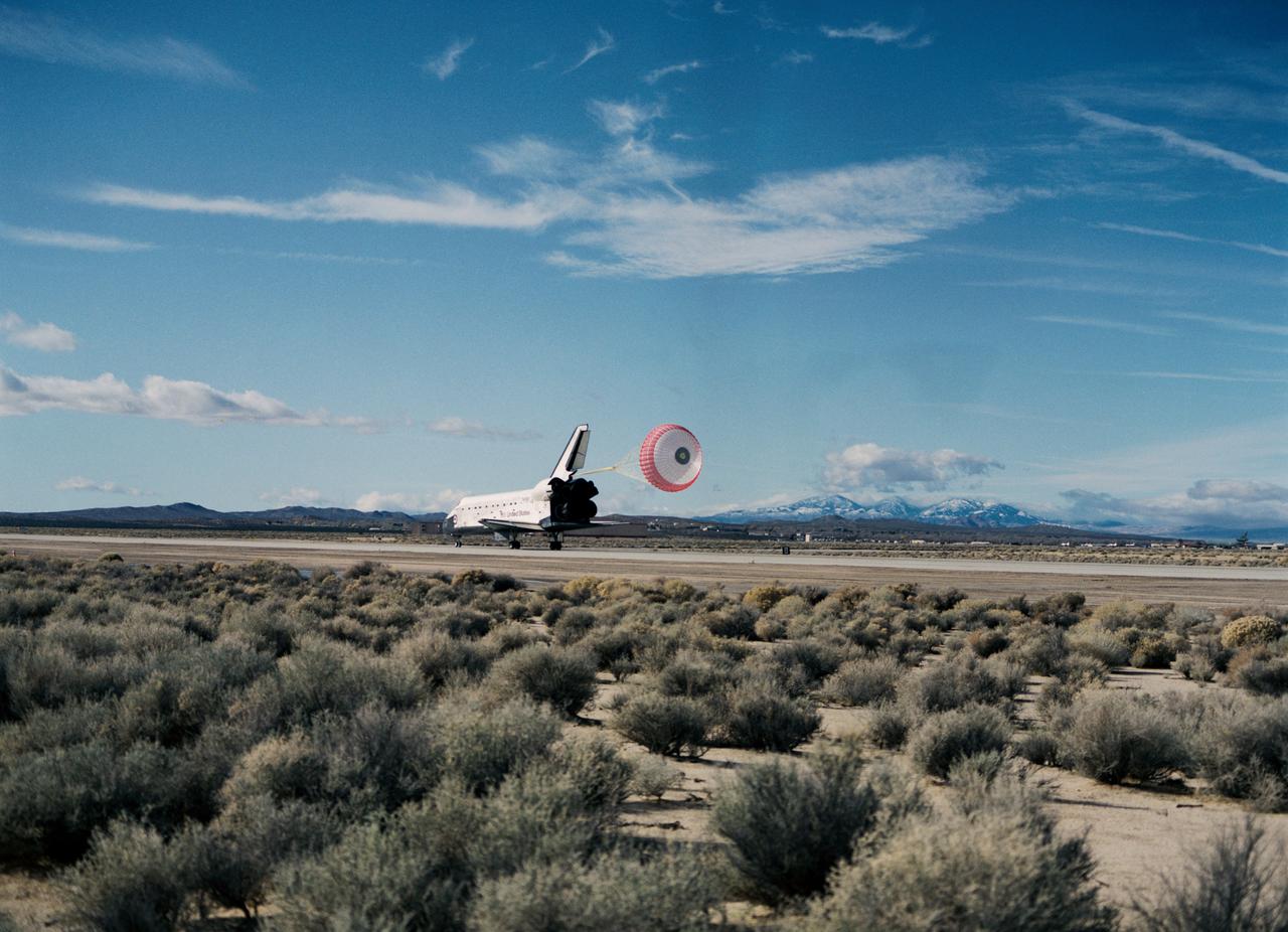
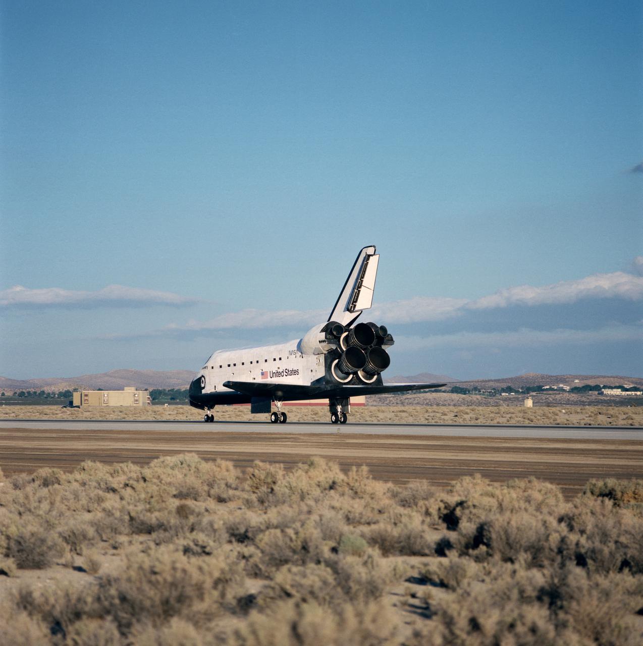
STS-53 Discovery, Orbiter Vehicle (OV) 103, is slowed by a red, white, and blue drag chute during its landing on concrete runway 22 at Edwards Air Force Base (EAFB), California. Main landing gear (MLG) touchdown occurred at 12:43:17 pm (Pacific Standard Time (PST)). This aft view of OV-103 shows the drag chute deployed from its compartment at the base of the vertical tail, the speedbrake/rudder flaps open, and the space shuttle main engines (SSMEs). Both MLG and nose landing gear (NLG) ride along the runway surface. Desert scrub brush appears in the foreground and mountains are seen in the background.
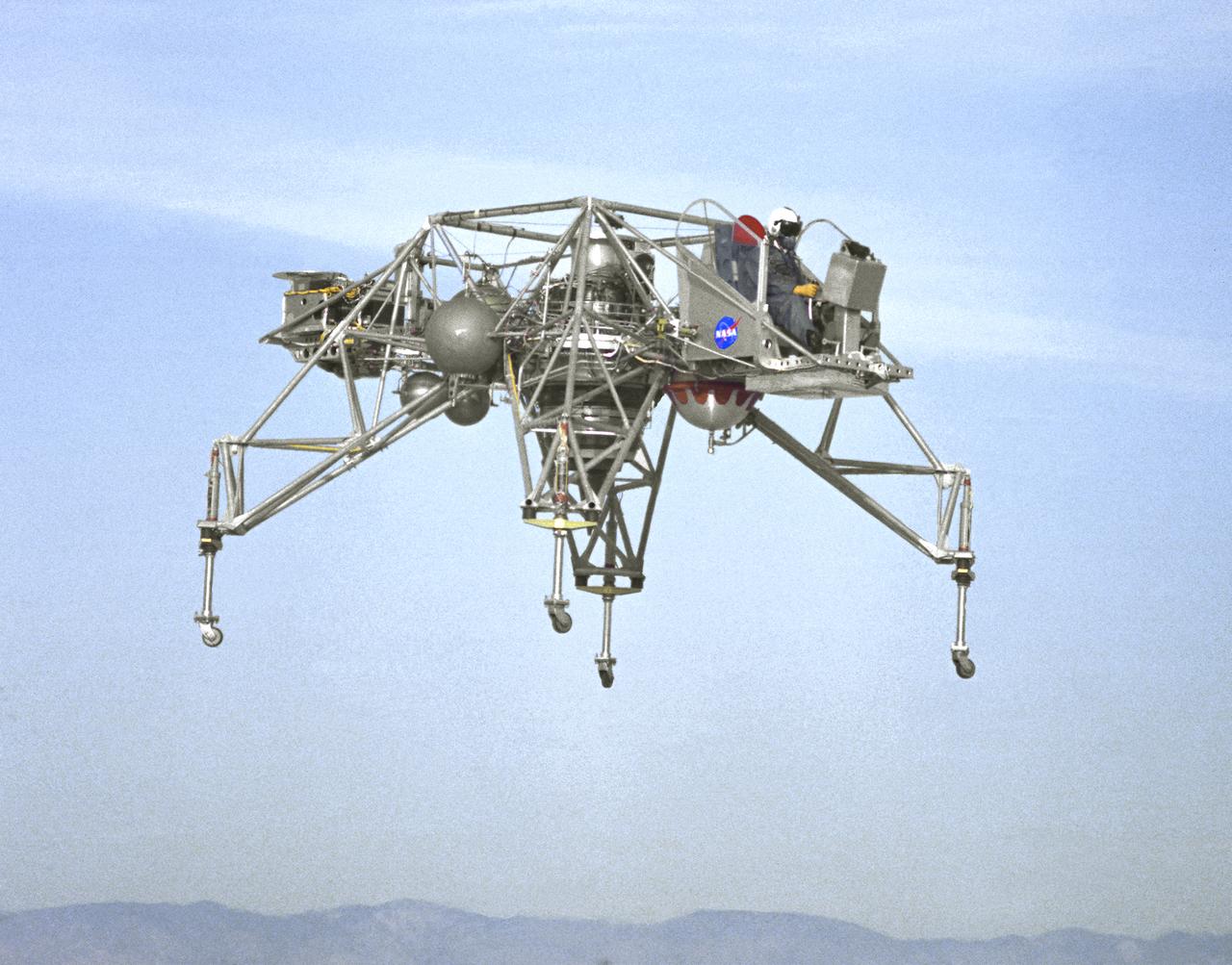
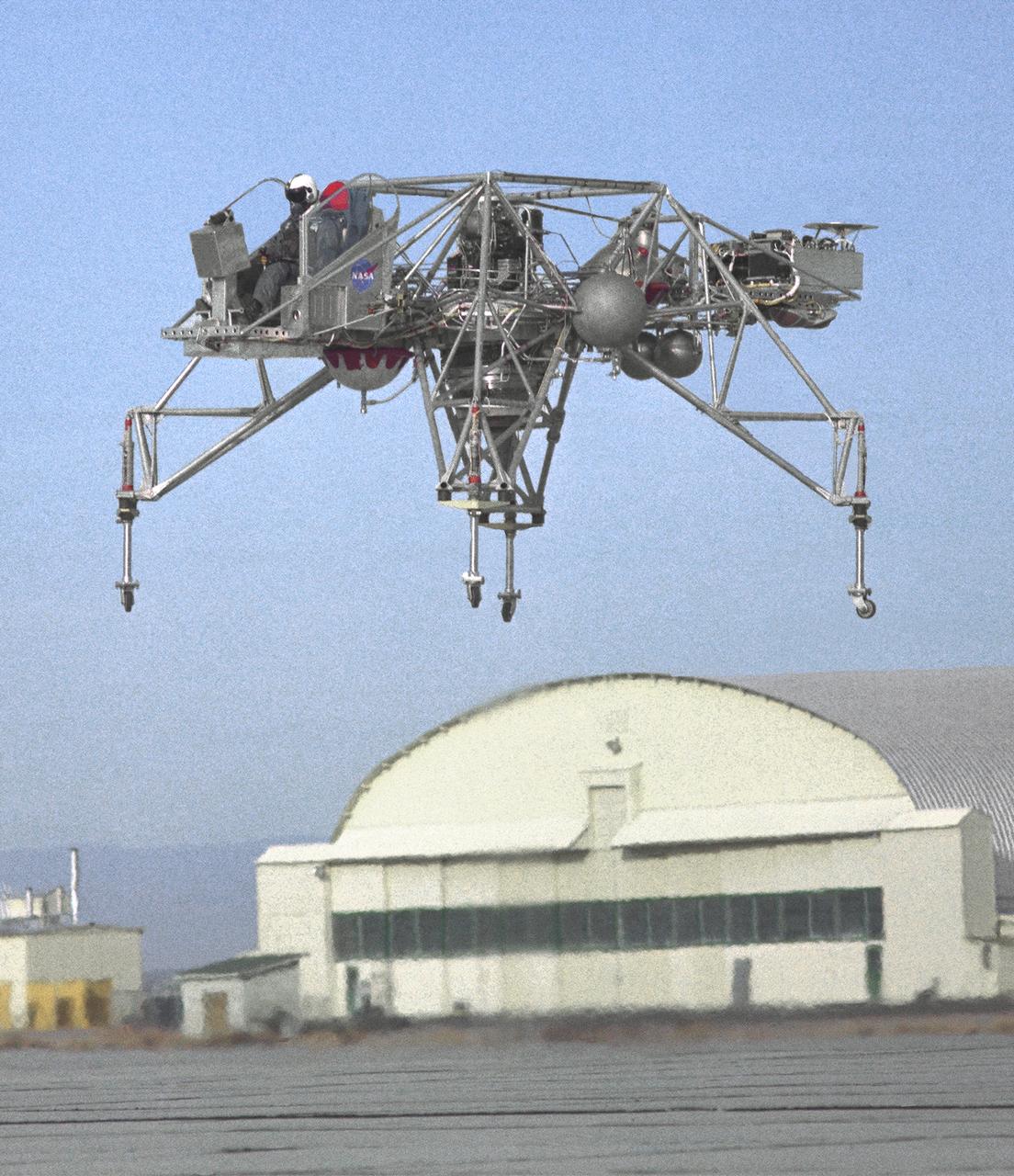
In this NASA Flight Reserch Center photograph the Lunar Landing Research Vehicle (LLRV) number 1 is shown in flight. When Apollo planning was underway in 1960, NASA was looking for a simulator to profile the descent to the Moon's surface. Three concepts surfaced: an electronic simulator, a tethered device, and the ambitious Dryden contribution, a free-flying vehicle. All three became serious projects, but eventually the NASA Flight Research Center's (FRC) Landing Research Vehicle (LLRV) became the most significant one. Hubert M. Drake is credited with originating the idea, while Donald Bellman and Gene Matranga were senior engineers on the project, with Bellman, the project manager. Simultaneously, and independently, Bell Aerosystems Company, Buffalo, N.Y., a company with experience in vertical takeoff and landing (VTOL) aircraft, had conceived a similar free-flying simulator and proposed their concept to NASA headquarters. NASA Headquarters put FRC and Bell together to collaborate. The challenge was; to allow a pilot to make a vertical landing on Earth in a simulated Moon environment, one sixth of the Earth's gravity and with totally transparent aerodynamic forces in a "free flight" vehicle with no tether forces acting on it. Built of tubular aluminum like a giant four-legged bedstead, the vehicle was to simulate a lunar landing profile from around 1500 feet to the Moon's surface. To do this, the LLRV had a General Electric CF-700-2V turbofan engine mounted vertically in gimbals, with 4200 pounds of thrust. The engine, using JP-4 fuel, got the vehicle up to the test altitude and was then throttled back to support five-sixths of the vehicle's weight, simulating the reduced gravity of the Moon. Two hydrogen-peroxide lift rockets with thrust that could be varied from 100 to 500 pounds handled the LLRV's rate of descent and horizontal translations. Sixteen smaller hydrogen-peroxide rockets, mounted in pairs, gave the pilot control in pitch, yaw, and roll. On the LLRV,
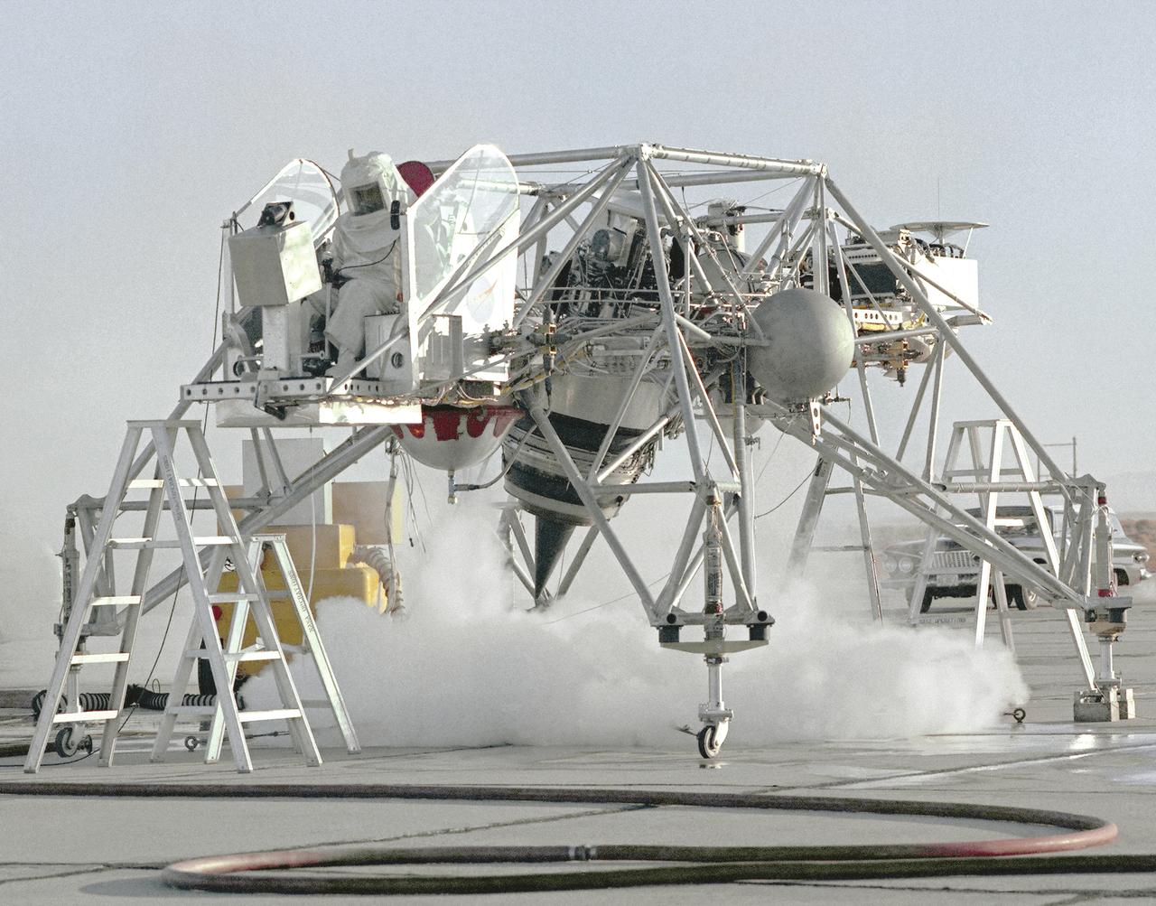
This 1964 NASA Flight Reserch Center photograph shows a ground engine test underway on the Lunar Landing Research Vehicle (LLRV) number 1. When Apollo planning was underway in 1960, NASA was looking for a simulator to profile the descent to the Moon's surface. Three concepts surfaced: an electronic simulator, a tethered device, and the ambitious Dryden contribution, a free-flying vehicle. All three became serious projects, but eventually the NASA Flight Research Center's (FRC) Landing Research Vehicle (LLRV) became the most significant one. Hubert M. Drake is credited with originating the idea, while Donald Bellman and Gene Matranga were senior engineers on the project, with Bellman, the project manager. Simultaneously, and independently, Bell Aerosystems Company, Buffalo, N.Y., a company with experience in vertical takeoff and landing (VTOL) aircraft, had conceived a similar free-flying simulator and proposed their concept to NASA headquarters. NASA Headquarters put FRC and Bell together to collaborate. The challenge was; to allow a pilot to make a vertical landing on Earth in a simulated Moon environment, one sixth of the Earth's gravity and with totally transparent aerodynamic forces in a "free flight" vehicle with no tether forces acting on it. Built of tubular aluminum like a giant four-legged bedstead, the vehicle was to simulate a lunar landing profile from around 1500 feet to the Moon's surface. To do this, the LLRV had a General Electric CF-700-2V turbofan engine mounted vertically in gimbals, with 4200 pounds of thrust. The engine, using JP-4 fuel, got the vehicle up to the test altitude and was then throttled back to support five-sixths of the vehicle's weight, simulating the reduced gravity of the Moon. Two hydrogen-peroxide lift rockets with thrust that could be varied from 100 to 500 pounds handled the LLRV's rate of descent and horizontal translations. Sixteen smaller hydrogen-peroxide rockets, mounted in pairs, gave the pilot control in pitch, yaw,
An inflight view from the left side of the Lunar Landing Research Vehicle, is shown in this 1964 NASA Flight Research Center photograph. The photograph was taken in front of the old NACA hangar located at the South Base, Edwards Air Force Base. When Apollo planning was underway in 1960, NASA was looking for a simulator to profile the descent to the Moon's surface. Three concepts surfaced: an electronic simulator, a tethered device, and the ambitious Dryden contribution, a free-flying vehicle. All three became serious projects, but eventually the NASA Flight Research Center's (FRC) Landing Research Vehicle (LLRV) became the most significant one. Hubert M. Drake is credited with originating the idea, while Donald Bellman and Gene Matranga were senior engineers on the project, with Bellman, the project manager. Simultaneously, and independently, Bell Aerosystems Company, Buffalo, N.Y., a company with experience in vertical takeoff and landing (VTOL) aircraft, had conceived a similar free-flying simulator and proposed their concept to NASA headquarters. NASA Headquarters put FRC and Bell together to collaborate. The challenge was; to allow a pilot to make a vertical landing on earth in a simulated Moon environment, one sixth of the earth's gravity and with totally transparent aerodynamic forces in a "free flight" vehicle with no tether forces acting on it. Built of tubular aluminum like a giant four-legged bedstead, the vehicle was to simulate a lunar landing profile from around 1500 feet to the Moon's surface. To do this, the LLRV had a General Electric CF-700-2V turbofan engine mounted vertically in gimbals, with 4200 pounds of thrust. The engine, using JP-4 fuel, got the vehicle up to the test altitude and was then throttled back to support five-sixths of the vehicle's weight, simulating the reduced gravity of the Moon. Two hydrogen-peroxide lift rockets with thrust that could be varied from 100 to 500 pounds handled the LLRV's rate of descent and horizontal transla
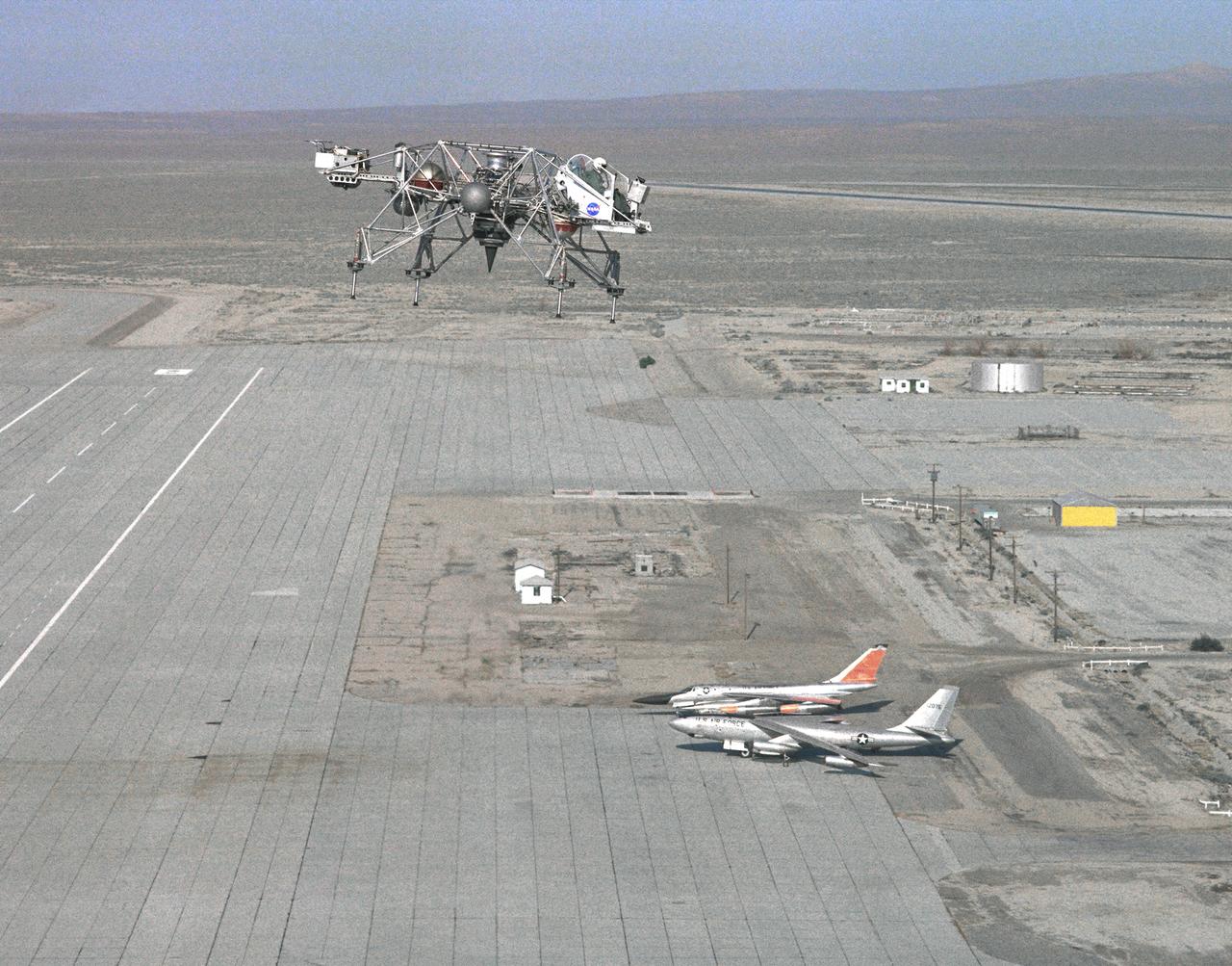
In this 1965 NASA Flight Reserch Center photograph the Lunar Landing Research Vehicle (LLRV) is shown at near maximum altitude over the south base at Edwards Air Force Base. When Apollo planning was underway in 1960, NASA was looking for a simulator to profile the descent to the moon's surface. Three concepts surfaced: an electronic simulator, a tethered device, and the ambitious Dryden contribution, a free-flying vehicle. All three became serious projects, but eventually the NASA Flight Research Center's (FRC) Landing Research Vehicle (LLRV) became the most significant one. Hubert M. Drake is credited with originating the idea, while Donald Bellman and Gene Matranga were senior engineers on the project, with Bellman, the project manager. Simultaneously, and independently, Bell Aerosystems Company, Buffalo, N.Y., a company with experience in vertical takeoff and landing (VTOL) aircraft, had conceived a similar free-flying simulator and proposed their concept to NASA headquarters. NASA Headquarters put FRC and Bell together to collaborate. The challenge was; to allow a pilot to make a vertical landing on Earth in a simulated moon environment, one sixth of the Earth's gravity and with totally transparent aerodynamic forces in a "free flight" vehicle with no tether forces acting on it. Built of tubular aluminum like a giant four-legged bedstead, the vehicle was to simulate a lunar landing profile from around 1500 feet to the moon's surface. To do this, the LLRV had a General Electric CF-700-2V turbofan engine mounted vertically in gimbals, with 4200 pounds of thrust. The engine, using JP-4 fuel, got the vehicle up to the test altitude and was then throttled back to support five-sixths of the vehicle's weight, simulating the reduced gravity of the moon. Two hydrogen-peroxide lift rockets with thrust that could be varied from 100 to 500 pounds handled the LLRV's rate of descent and horizontal translations. Sixteen smaller hydrogen-peroxide rockets, mounted in pairs, gav
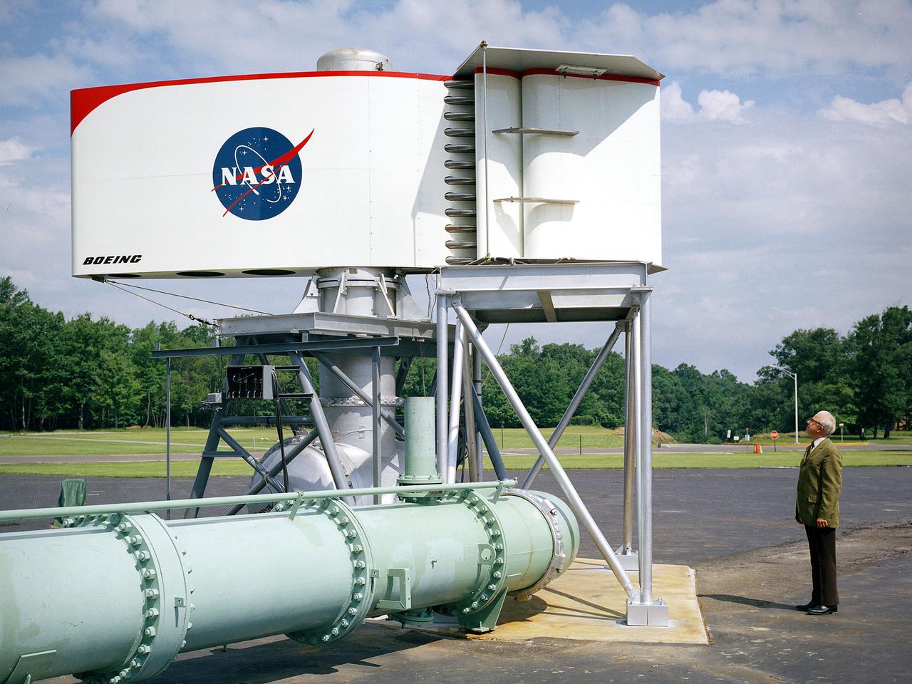
The augmentor wing concept was introduced during the early 1960s to enhance the performance of vertical and short takeoff (VSTOL) aircraft. The leading edge of the wing has full-span vertical flaps, and the trailing edge has double-slotted flaps. This provides aircraft with more control in takeoff and landing conditions. The augmentor wing also produced lower noise levels than other VSTOL designs. In the early 1970s Boeing Corporation built a Buffalo C-8A augmentor wing research aircraft for Ames Research Center. Researches at Lewis Research Center concentrated their efforts on reducing the noise levels of the wing. They initially used small-scale models to develop optimal nozzle screening methods. They then examined the nozzle designs on a large-scale model, seen here on an external test stand. This test stand included an airflow system, nozzle, the augmentor wing, and a muffler system below to reduce the atmospheric noise levels. The augmentor was lined with noise-reducing acoustic panels. The Lewis researchers were able to adjust the airflow to simulate conditions at takeoff and landing. Once the conditions were stabilized they took noise measurements from microphones placed in all directions from the wing, including an aircraft flying over. They found that the results coincided with the earlier small-scale studies for landing situations but not takeoffs. The acoustic panels were found to be successful.
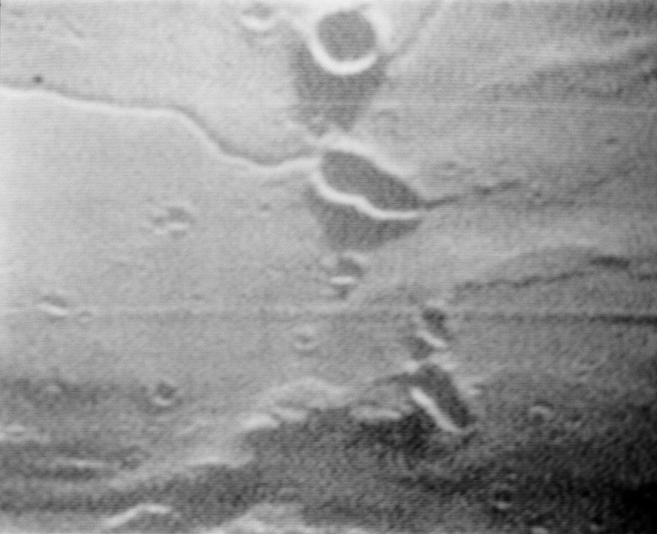
S69-39541 (19 July 1969) --- A near vertical view of Diamondback Rille is seen in this color reproduction taken from the fourth color television transmission from the Apollo 11 spacecraft, during its second revolution of the moon. The center of the picture is located at about 26.9 degrees east longitude and 1.2 degrees north latitude. This area is just east of the Apollo Landing Site 2. The crew of the Apollo 11 lunar landing mission is astronauts Neil A. Armstrong, commander; Michael Collins, command module pilot; and Edwin E. Aldrin Jr., lunar module pilot.
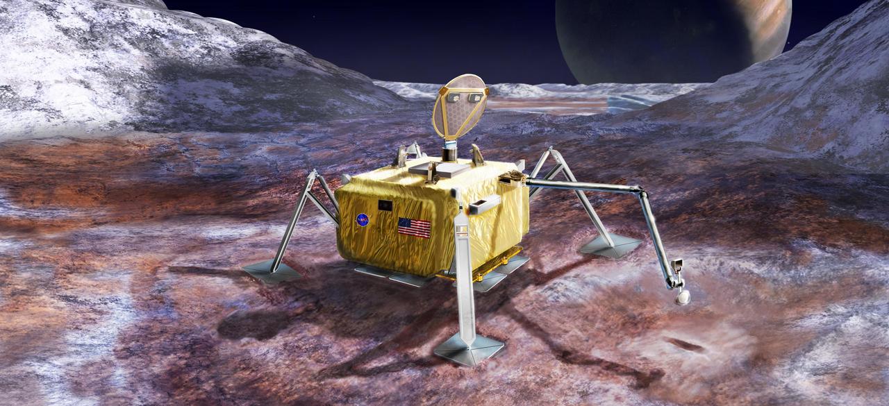
This artist's rendering illustrates a conceptual design for a potential future mission to land a robotic probe on the surface of Jupiter's moon Europa. The lander is shown with a sampling arm extended, having previously excavated a small area on the surface. The circular dish on top is a dual-purpose high-gain antenna and camera mast, with stereo imaging cameras mounted on the back of the antenna. Three vertical shapes located around the top center of the lander are attachment points for cables that would lower the rover from a sky crane, which is envisioned as the landing system for this mission concept. http://photojournal.jpl.nasa.gov/catalog/PIA21048
STS-31 Discovery, Orbiter Vehicle (OV) 103, rolls along concrete runway 22 at Edwards Air Force Base (EAFB), California, after nose landing gear (NLG) and main landing gear (MLG) touchdown. This view looks down OV-103's port side from the space shuttle main engines (SSMEs) to the nose section. The SSMEs are gimbaled to their descent position and the rudder/speedbrake is deployed on the vertical stabilizer. Wheel stop occurred at 6:51 am (Pacific Daylight Time (PDT)). In the distance EAFB facilities are visible.
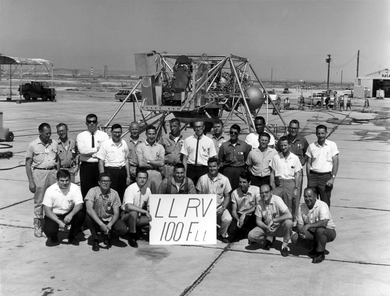
A group photo of the LLRV personnel following the program's 100th flight. The photo was taken at South Base, and was near the hangar first used by the original NACA group, at what was then called Muroc. When Apollo planning was underway in 1960, NASA was looking for a simulator to profile the descent to the moon's surface. Three concepts surfaced: an electronic simulator, a tethered device, and the ambitious Dryden contribution, a free-flying vehicle. All three became serious projects, but eventually the NASA Flight Research Center's (FRC) Landing Research Vehicle (LLRV) became the most significant one. Hubert M. Drake is credited with originating the idea, while Donald Bellman and Gene Matranga were senior engineers on the project, with Bellman, the project manager. Simultaneously, and independently, Bell Aerosystems Company, Buffalo, N.Y., a company with experience in vertical takeoff and landing (VTOL) aircraft, had conceived a similar free-flying simulator and proposed their concept to NASA headquarters. NASA Headquarters put FRC and Bell together to collaborate. The challenge was; to allow a pilot to make a vertical landing on Earth in a simulated moon environment, one sixth of the Earth's gravity and with totally transparent aerodynamic forces in a "free flight" vehicle with no tether forces acting on it. Built of tubular aluminum like a giant four-legged bedstead, the vehicle was to simulate a lunar landing profile from around 1500 feet to the moon's surface. To do this, the LLRV had a General Electric CF-700-2V turbofan engine mounted vertically in gimbals, with 4200 pounds of thrust. The engine, using JP-4 fuel, got the vehicle up to the test altitude and was then throttled back to support five-sixths of the vehicle's weight, simulating the reduced gravity of the moon. Two hydrogen-peroxide lift rockets with thrust that could be varied from 100 to 500 pounds handled the LLRV's rate of descent and horizontal translations. Sixteen smaller hydrogen-peroxide r
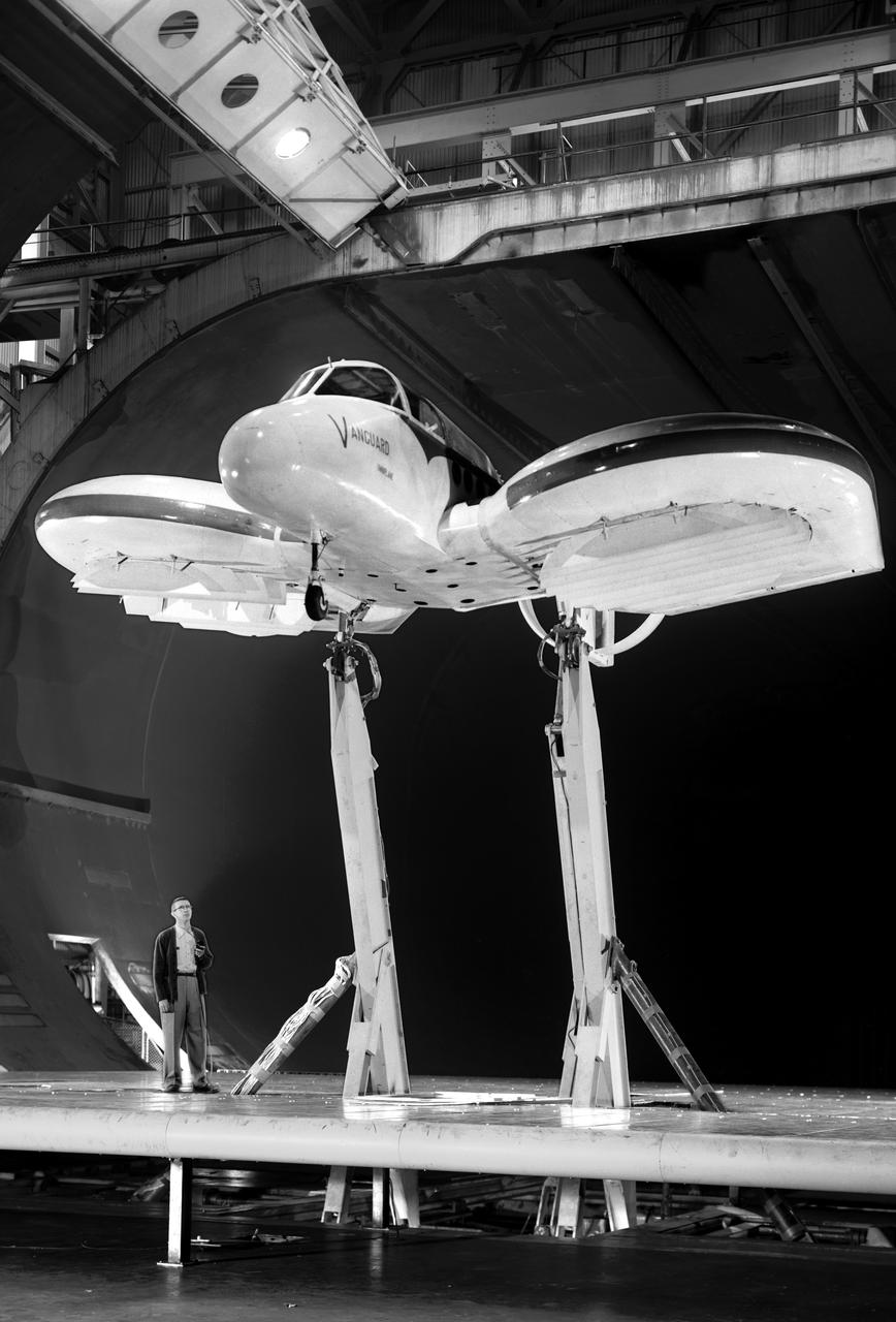
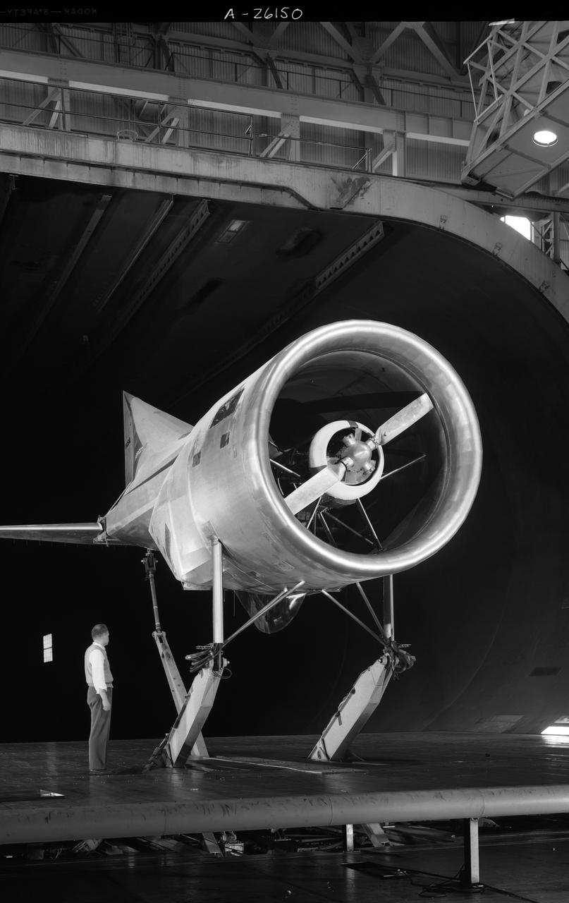
Vanguard 2C vertical take-off and landing (VTOL) airplane, wind tunnel test. Front view from below, model 14 1/2 feet high disk off. Nasa Ames engineer Ralph Maki in photo. Variable height struts and ground plane, low pressure ratio, fan in wing. 02/01/1960.
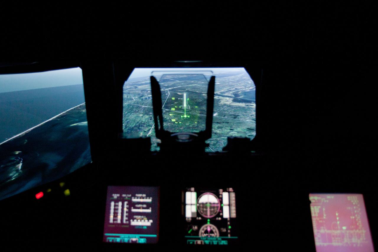
JSC2011-E-040200 (2 March 2011) --- The landing approach to the Kennedy Space Center is seen in a heads up display as the STS-135 crew trains in the Vertical Motion Simulator (VMS) at NASA's Ames Research Center in Mountain View, Calif., on March 2, 2011. Photo credit: NASA Photo/Houston Chronicle, Smiley N. Pool
In the Astrotech facility at Vandenberg Air Force Base in California, the payload fairing for the United Launch Alliance (ULA) Atlas V for NASA's upcoming Interior Exploration using Seismic Investigations, Geodesy and Heat Transport, or InSight, mission to land on Mars is lifted to the vertical position. InSight is the first mission to explore the Red Planet's deep interior. It will investigate processes that shaped the rocky planets of the inner solar system including Earth. Liftoff atop a ULA Atlas V rocket is scheduled for May 5, 2018.
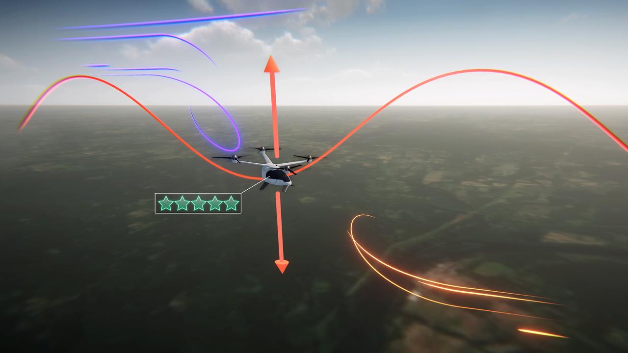
Electrical vertical takeoff and landing aircraft (eVTOLs), like the one shown in this concept art, could be a crucial part of the next generation of air transportation. In order to create a viable market, designers will have to create a comfortable passenger experience. NASA's Advanced Air Mobility mission is researching ride quality to better understand how these aircraft should be designed.

S72-01713 (July 1972) --- A vertical view of the Apollo 17 landing site in the Taurus-Littrow area of the lunar nearside, with an overlay showing the Lunar Roving Vehicle traverse proposed for the second extravehicular activity. The scale at the bottom is measured in kilometers. One kilometer equals 0.6214 statute miles. The coordinates of the Apollo 17 touchdown point are 30 degrees 44 minutes 58 seconds east longitude and 20 degrees 9 minutes 50 seconds north latitude. This photograph was taken from lunar orbit on an earlier Apollo mission.
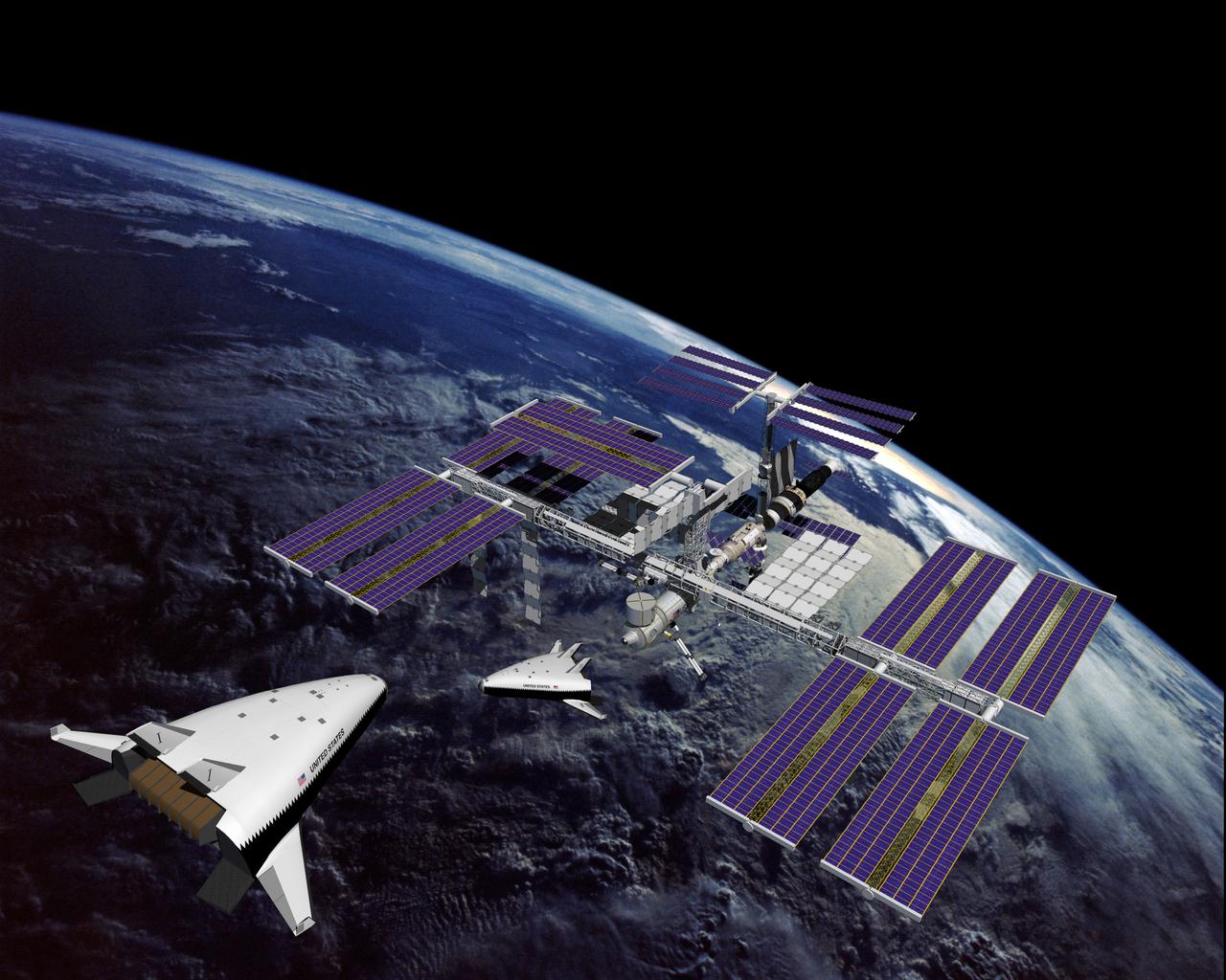
This is an artist's concept of the completely operational International Space Station being approached by an X-33 Reusable Launch Vehicle (RLV). The X-33 program was designed to pave the way to a full-scale, commercially developed RLV as the flagship technology demonstrator for technologies that would lower the cost of access to space. It is unpiloted, taking off vertically like a rocket, reaching an altitude of up to 60 miles and speeds between Mach 13 and 15, and landing horizontally like an airplane. The X-33 program was cancelled in 2001.
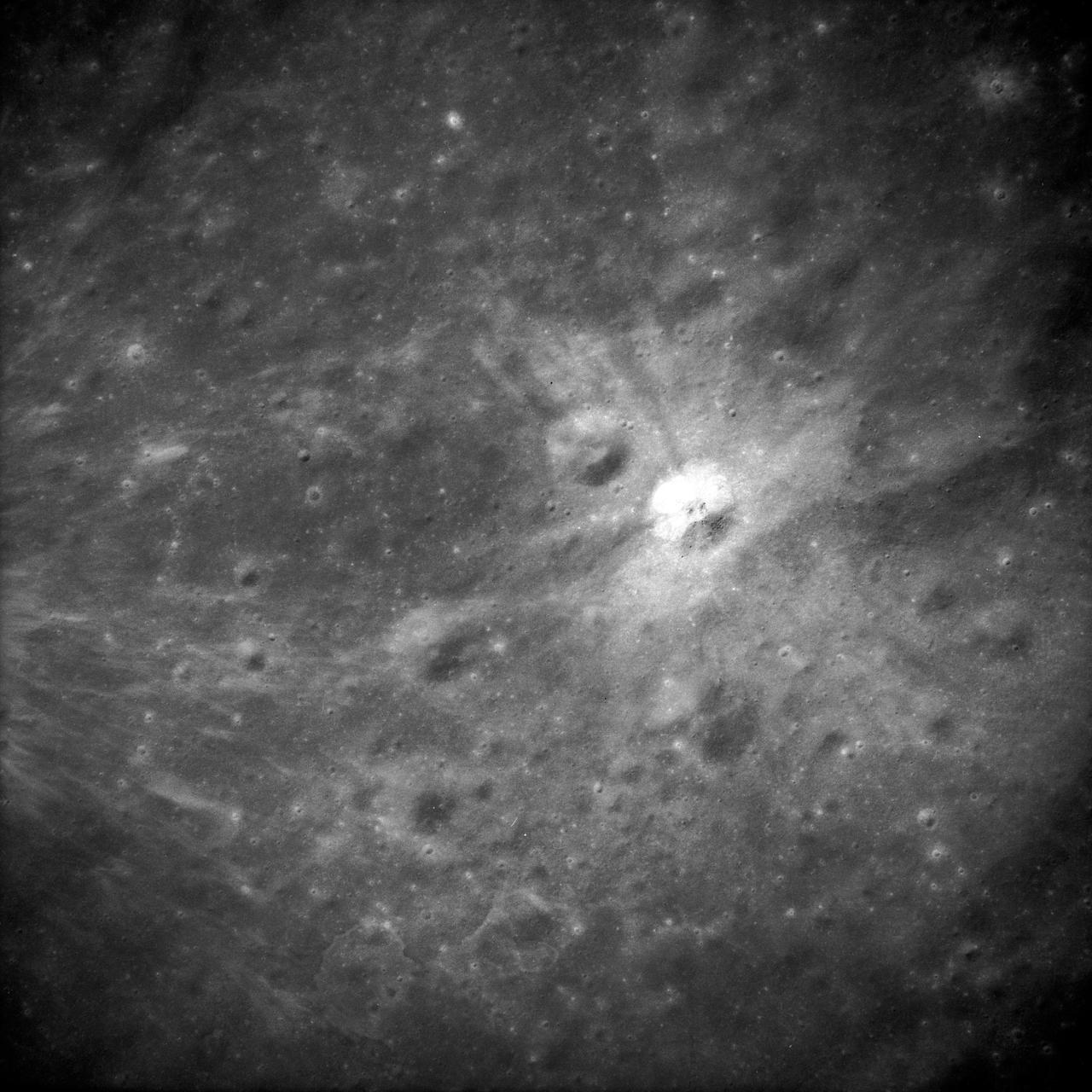
AS14-69-9560 (February 1971) --- This 500mm vertical frame taken from the Apollo 14 spacecraft is of the Apollo 16 proposed landing site "Descartes". The actual location of the target area is near the upper left. This photograph was taken with a 56 degree sun angle. The large bright crater is approximately one kilometer in diameter and has a distinctive ray pattern which serves as an excellent landmark.
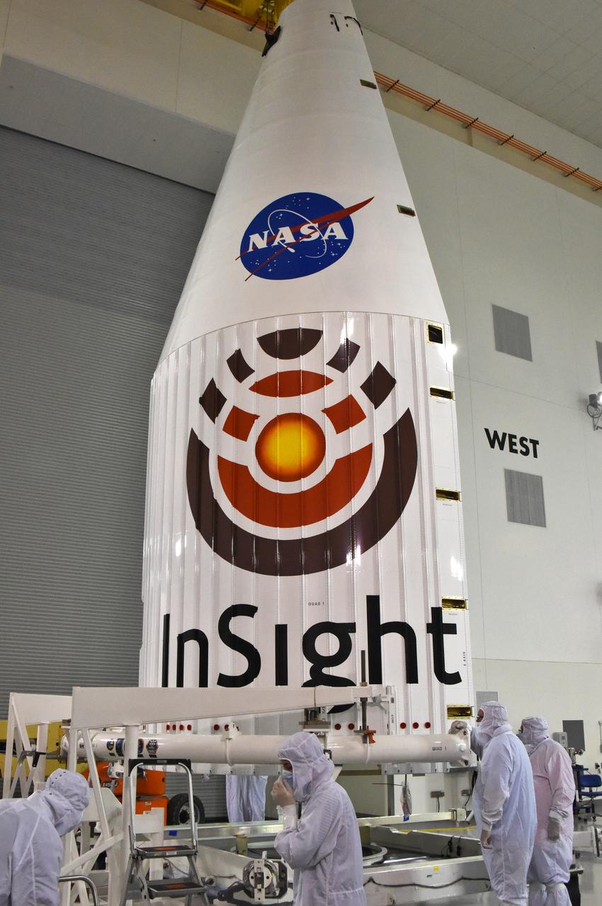
In the Astrotech facility at Vandenberg Air Force Base in California, technicians and engineers inspect the payload fairing for the United Launch Alliance (ULA) Atlas V for NASA's upcoming Interior Exploration using Seismic Investigations, Geodesy and Heat Transport, or InSight, mission to land on Mars after it was lifted to the vertical position. InSight is the first mission to explore the Red Planet's deep interior. It will investigate processes that shaped the rocky planets of the inner solar system including Earth. Liftoff atop a ULA Atlas V rocket is scheduled for May 5, 2018.

Curtis Flack (left) and Paul von Hardenberg (right) inspect the ice formation on the spinner of an Advanced Air Mobility proprotor model tested in the Icing Research Tunnel. The data from the test will be used by icing researchers to better understand the risks of icing on electric vertical takeoff and landing vehicles which will assist with the design and certification of new aircraft.
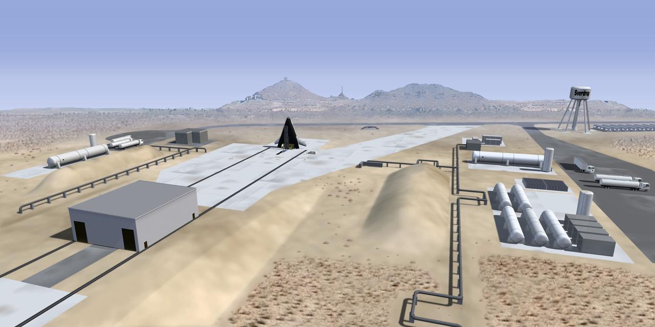
This is an artist's interpretation of a future launch complex for third generation propulsion reusable launch vehicles such as the X-33. The X-33 is a sub-scale technology demonstrator prototype of a Reusable Launch Vehicle (RLV), with a vertical take off / horizontal landing (lifting body) concept, which was manufactured and named as the Venture Star by Lockheed Martin. The X-33 program was cancelled in 2001.
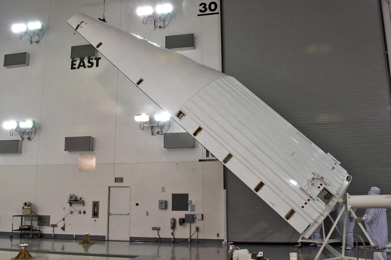
In the Astrotech facility at Vandenberg Air Force Base in California, the payload fairing for the United Launch Alliance (ULA) Atlas V for NASA's upcoming Interior Exploration using Seismic Investigations, Geodesy and Heat Transport, or InSight, mission to land on Mars is lifted to the vertical position. InSight is the first mission to explore the Red Planet's deep interior. It will investigate processes that shaped the rocky planets of the inner solar system including Earth. Liftoff atop a ULA Atlas V rocket is scheduled for May 5, 2018.