
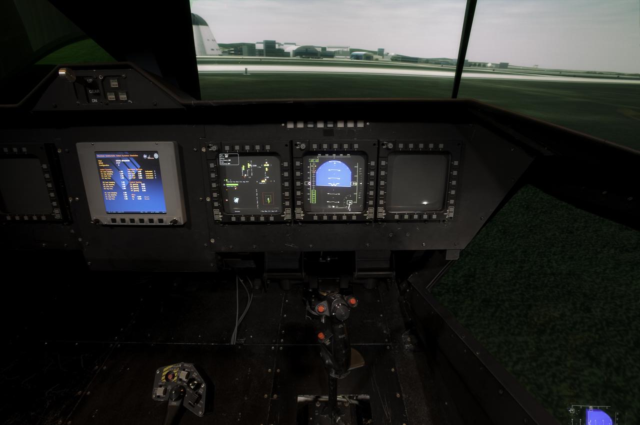
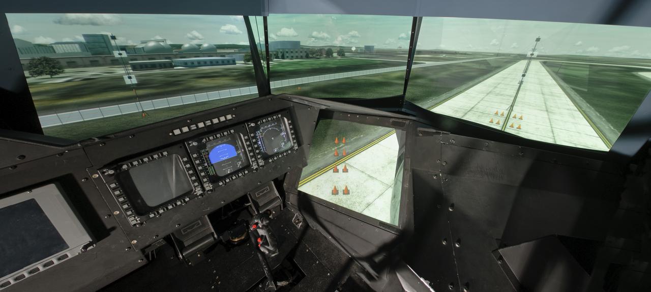
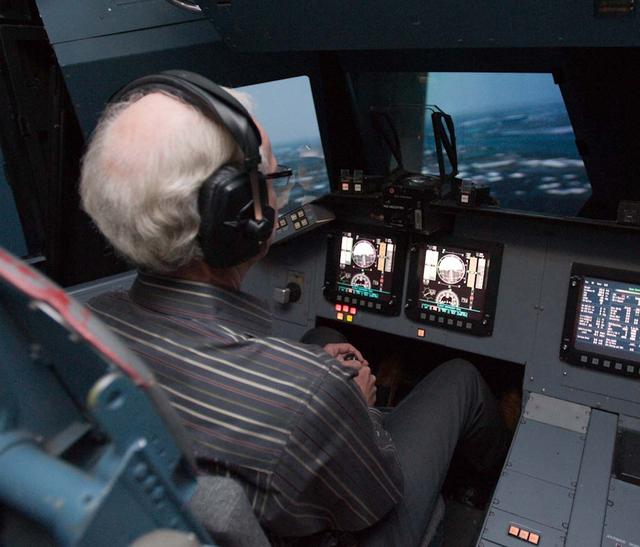
Out the window view of the ownship aircraft in the VMS’s R-Cab during the AVA-1h simulation in the VMS, N243.
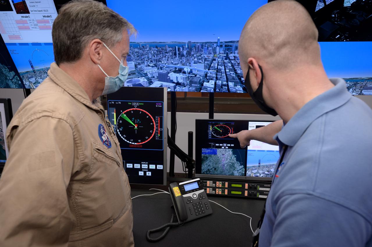
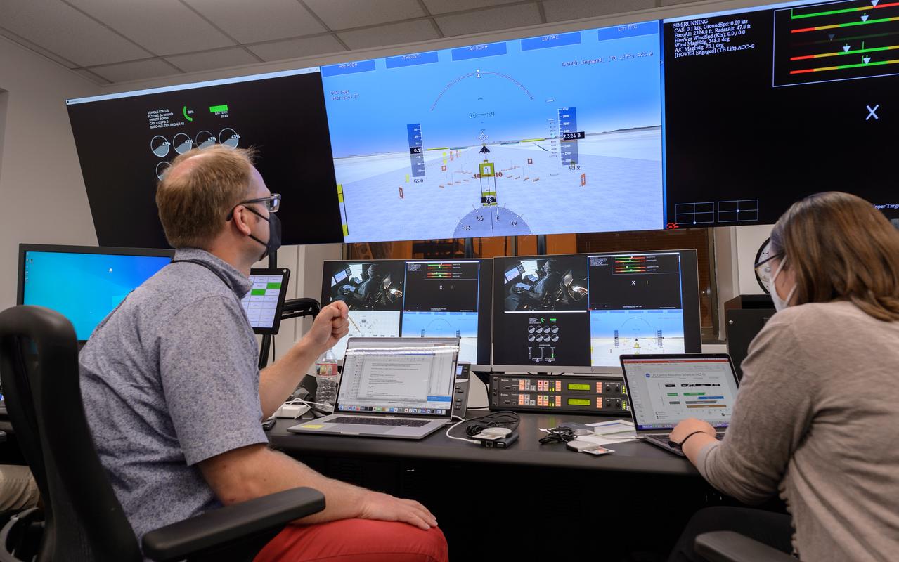
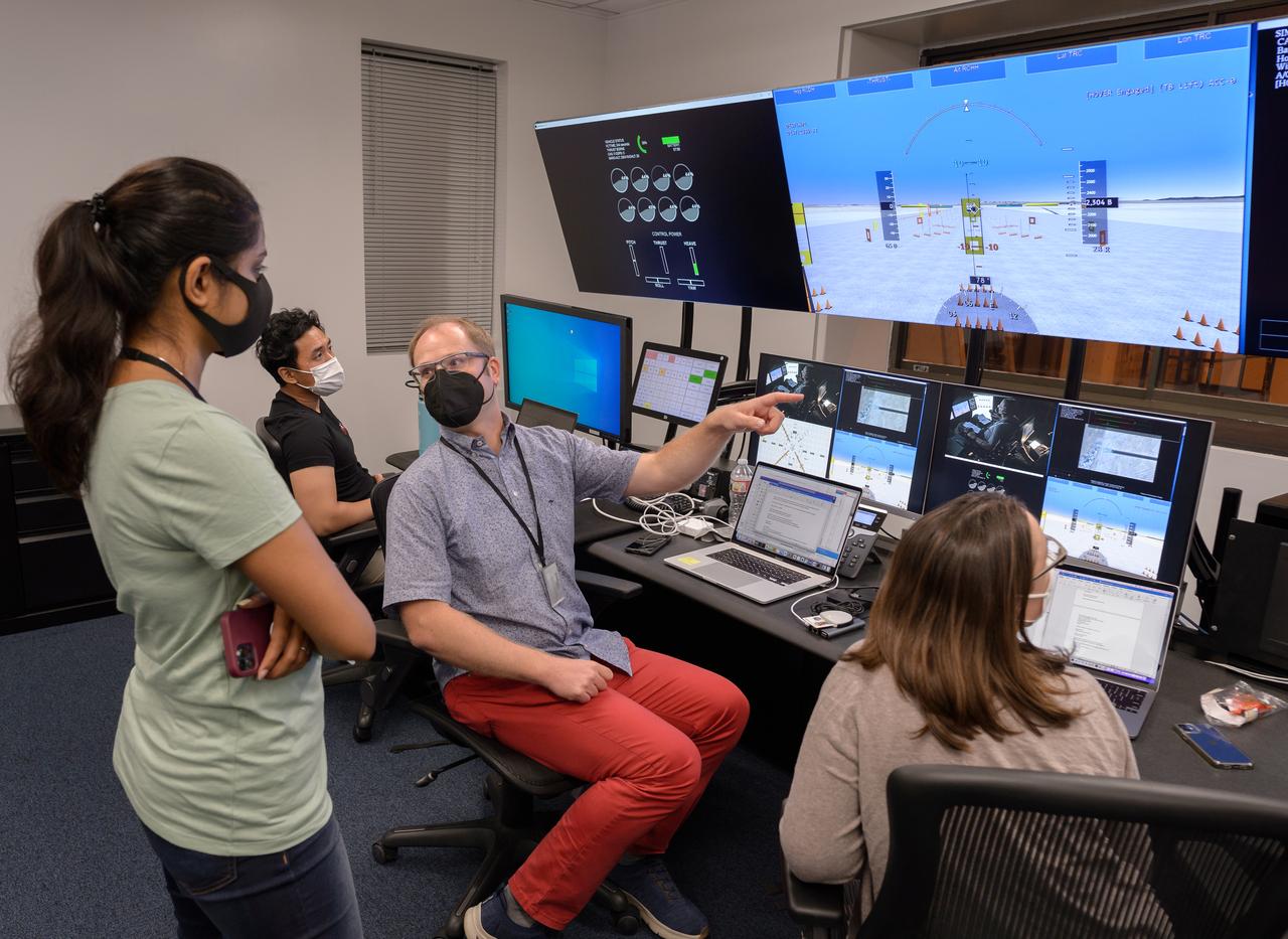
Human factors engineer Casey Smith, right, and pilot Wayne Ringelberg, left, discuss simulation results during a flight debrief in the VMS control room, N243.

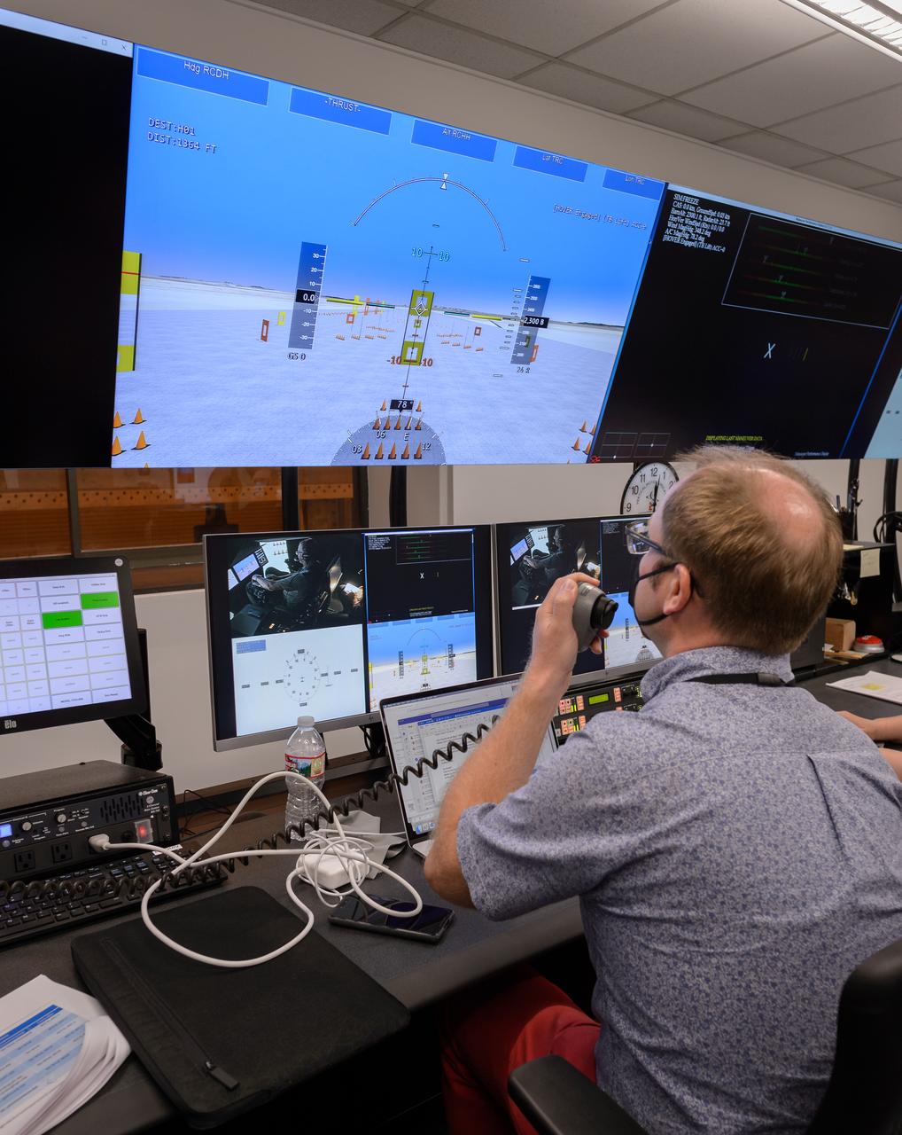
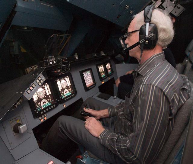
Pilot David Zahn fine-tunes the traffic display screen of the ownship aircraft in the VMS’s R-Cab during the AVA-1h simulation in the VMS, N243.

Traffic display screen of the ownship aircraft in the VMS’s R-Cab during the AVA-1h simulation in the VMS, N243.

Traffic display screen of the ownship aircraft in the VMS’s R-Cab during the AVA-1h simulation in the VMS, N243.

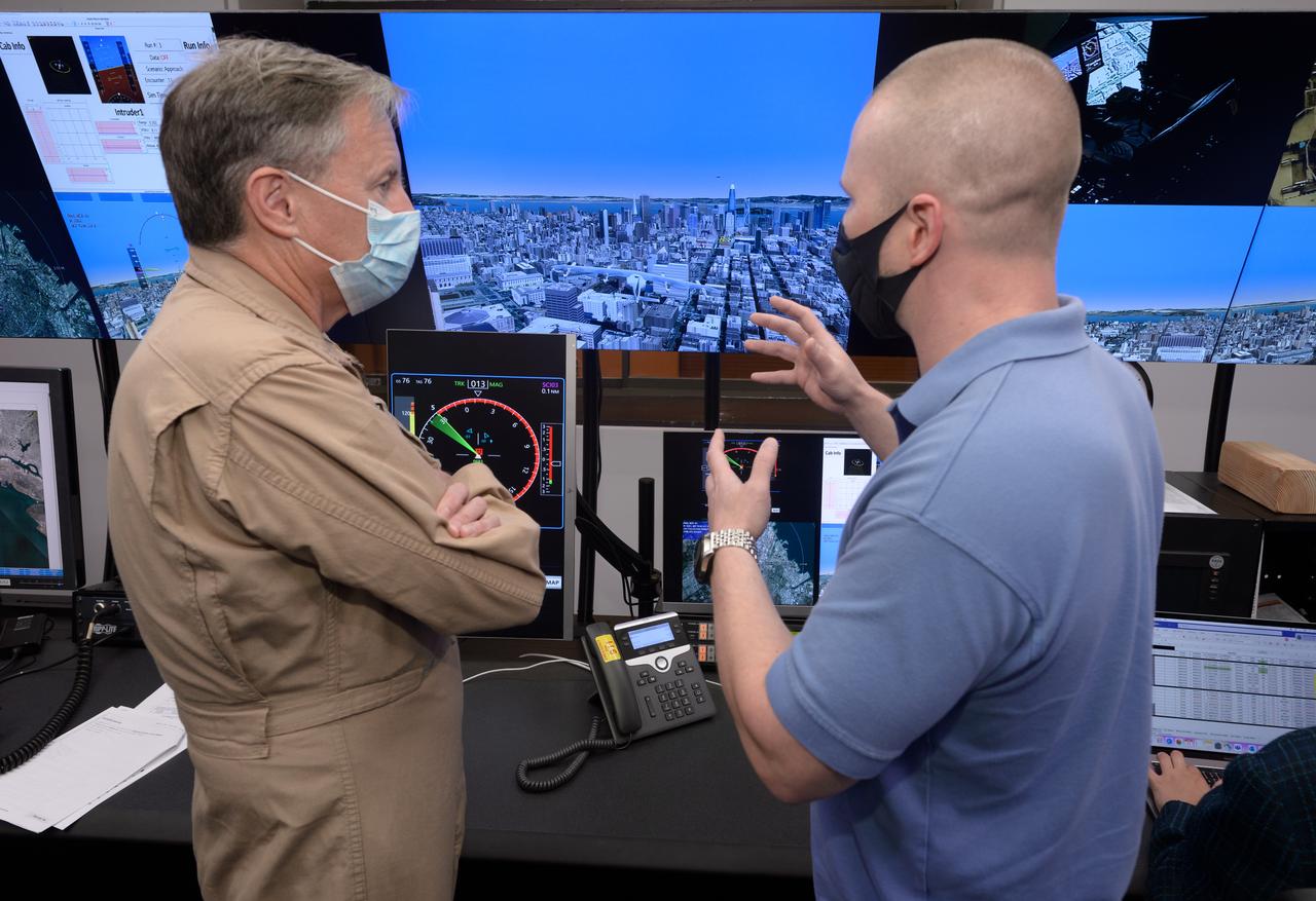
Human factors engineer Casey Smith, left, and pilot Wayne Ringelberg, right, discuss simulation results during a flight debrief in the VMS control room, N243.
Pilot David Zahn fine-tunes the traffic display screen of the ownship aircraft in the VMS’s R-Cab during the AVA-1h simulation in the VMS, N243.

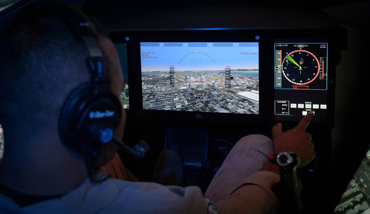
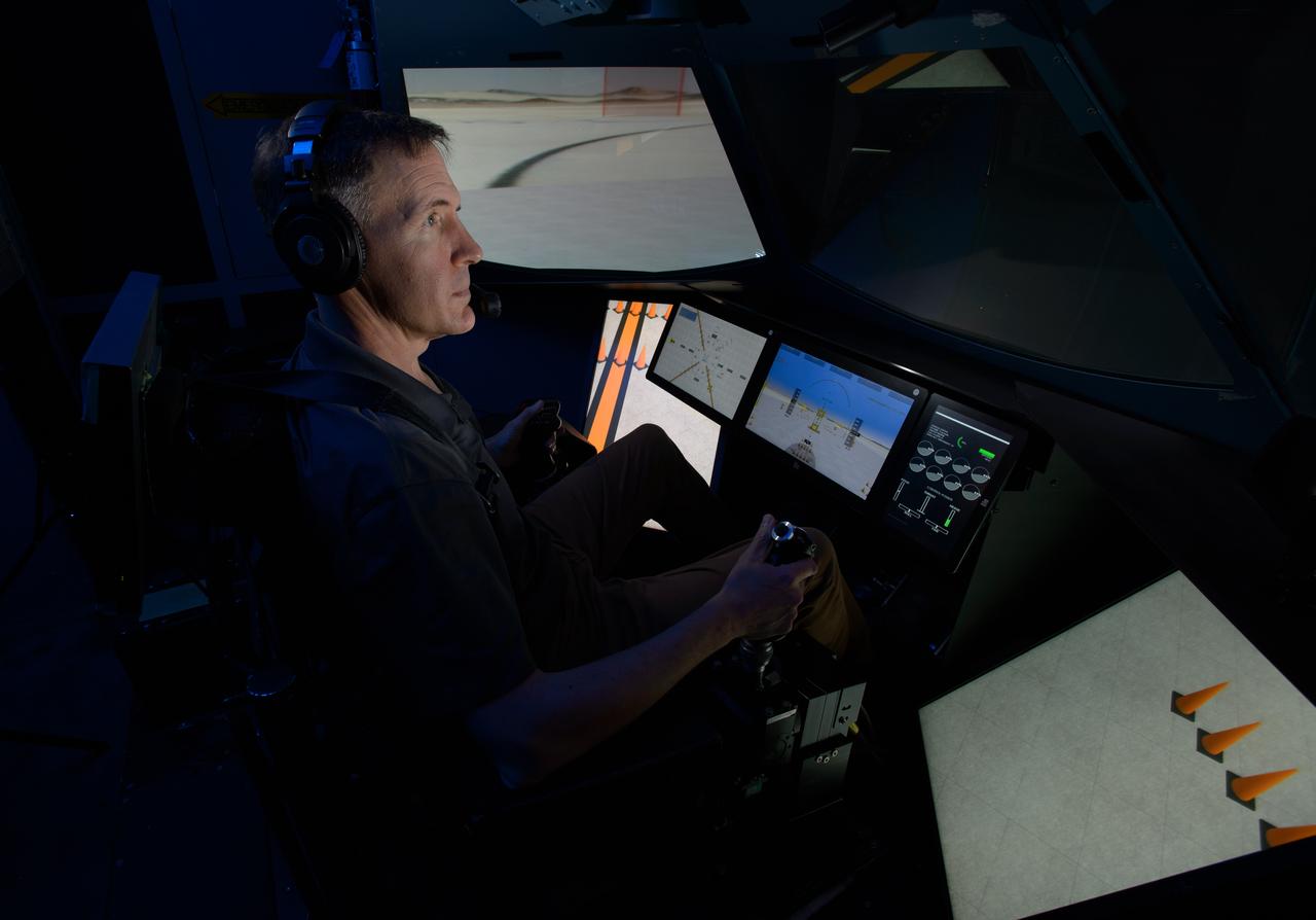
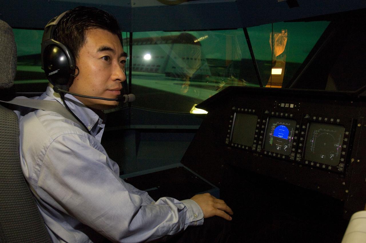
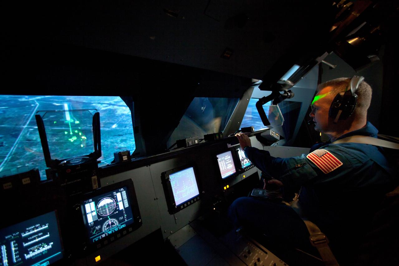
David Zahn pilots the ownship aircraft in the VMS’s R-Cab during the AVA-1h simulation in the VMS, N243.

Out the window view of the ownship aircraft in the VMS’s R-Cab during the AVA-1h simulation in the VMS, N243.

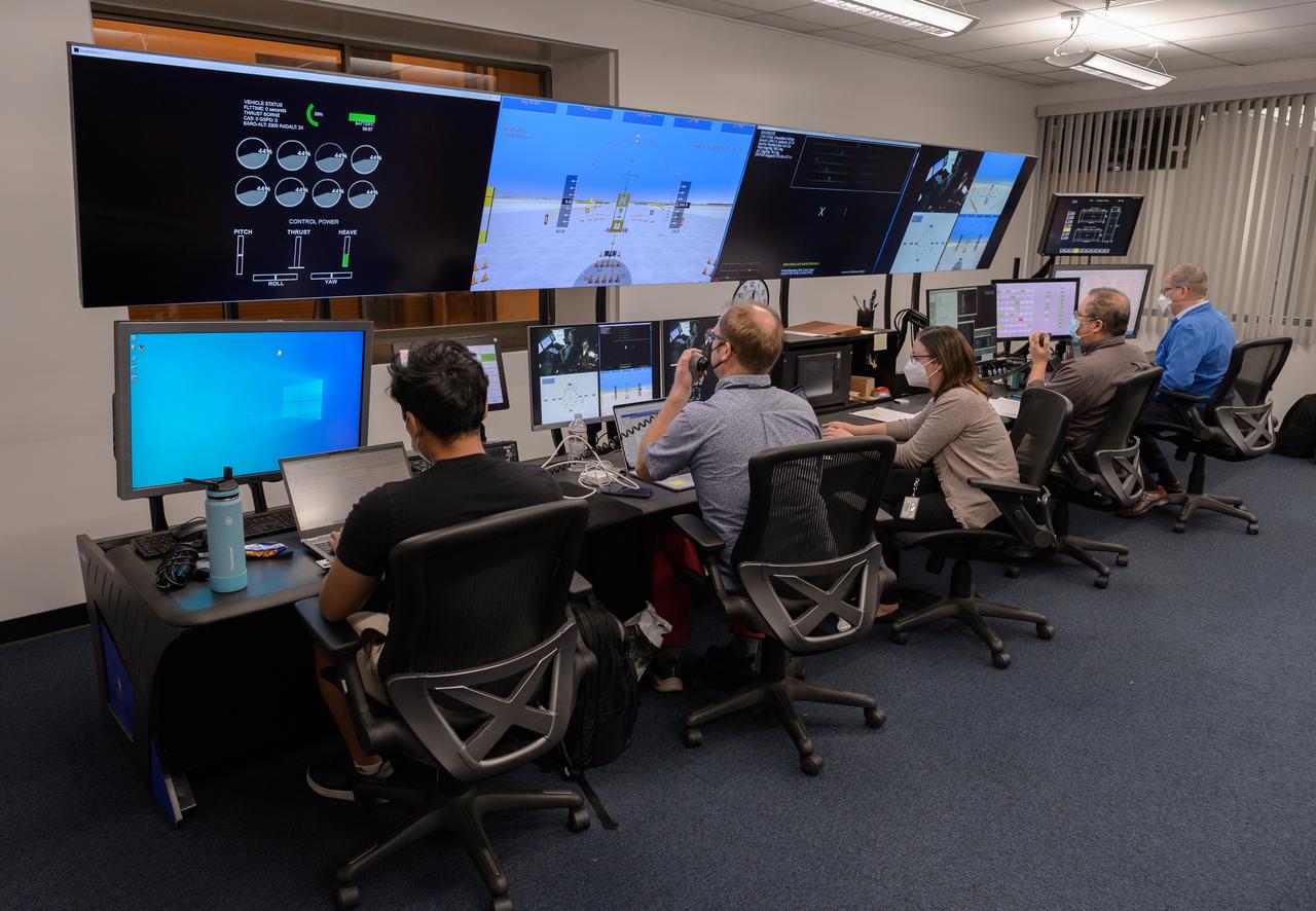
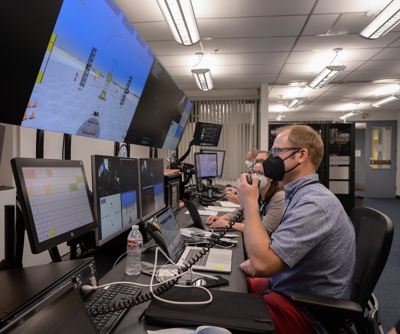
AVA-1h simulation team members Megan Mitchell, left, Christian Schmitz, and Matthew Blanken, right, in the VMS control room, N243, prepare for a simulation.

David Zahn pilots the ownship aircraft in the VMS’s R-Cab during the AVA-1h simulation in the VMS, N243.
Human factors engineer Casey Smith, right, and pilot Wayne Ringelberg, left, discuss simulation results during a flight debrief in the VMS control room, N243.
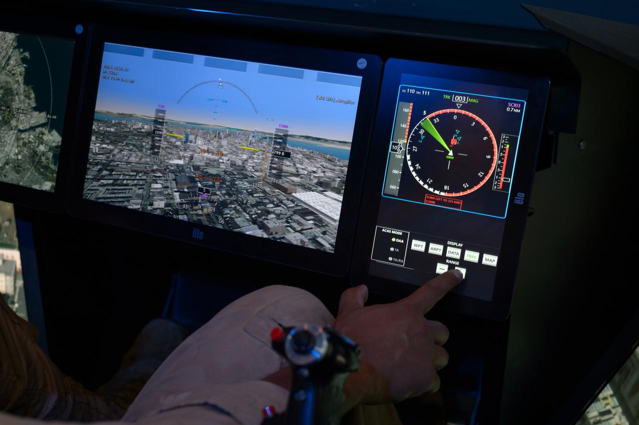
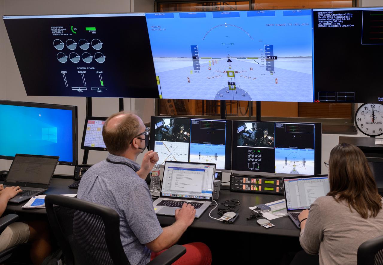
Primary flight display screen, left, and traffic display screen, right, of the ownship aircraft in the VMS’s R-Cab during the AVA-1h simulation in the VMS, N243.

Human factors engineer Casey Smith, left, and pilot Wayne Ringelberg, right, discuss simulation results during a flight debrief in the VMS control room, N243.

Out the window view of the ownship aircraft in the VMS’s R-Cab during the AVA-1h simulation in the VMS, N243.

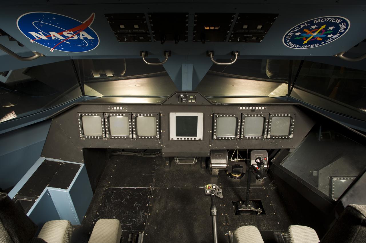
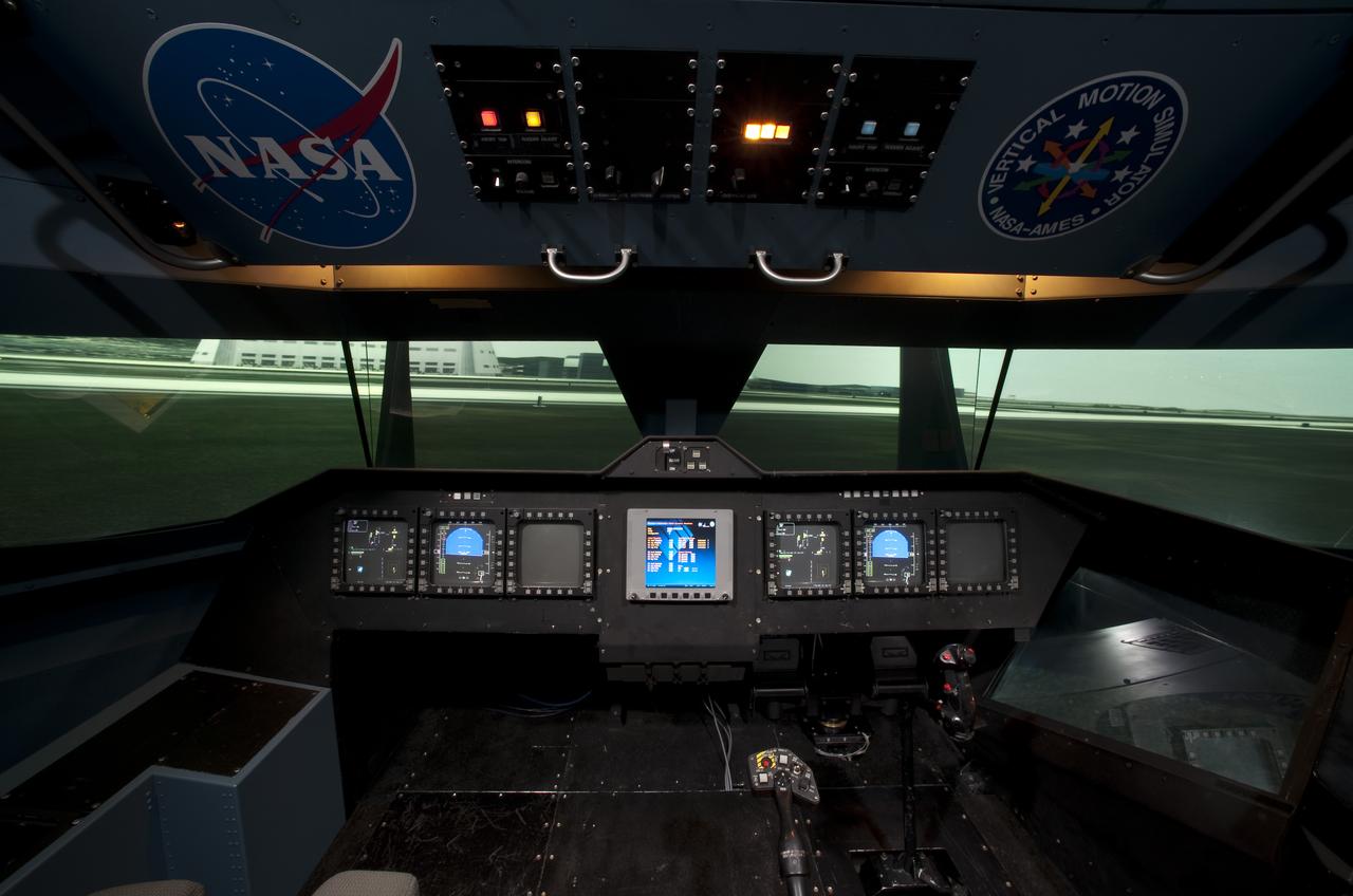
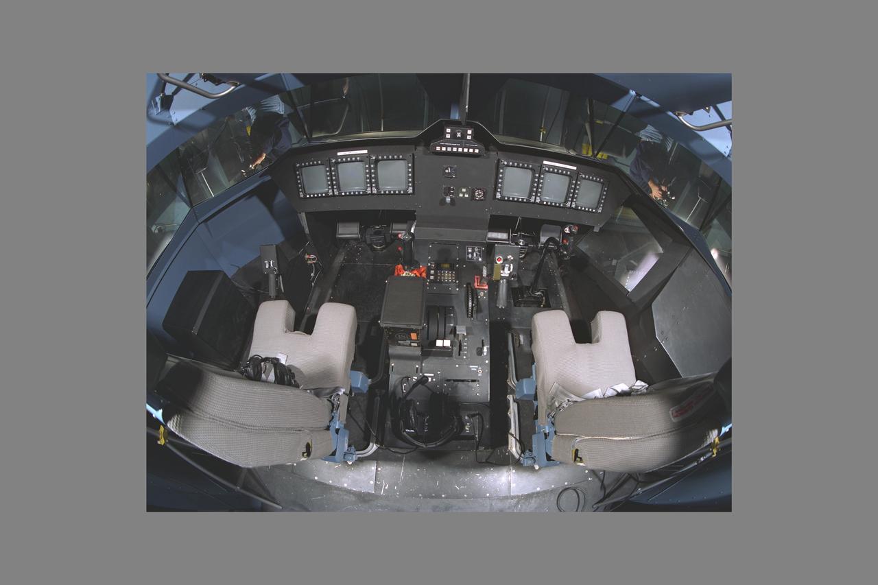
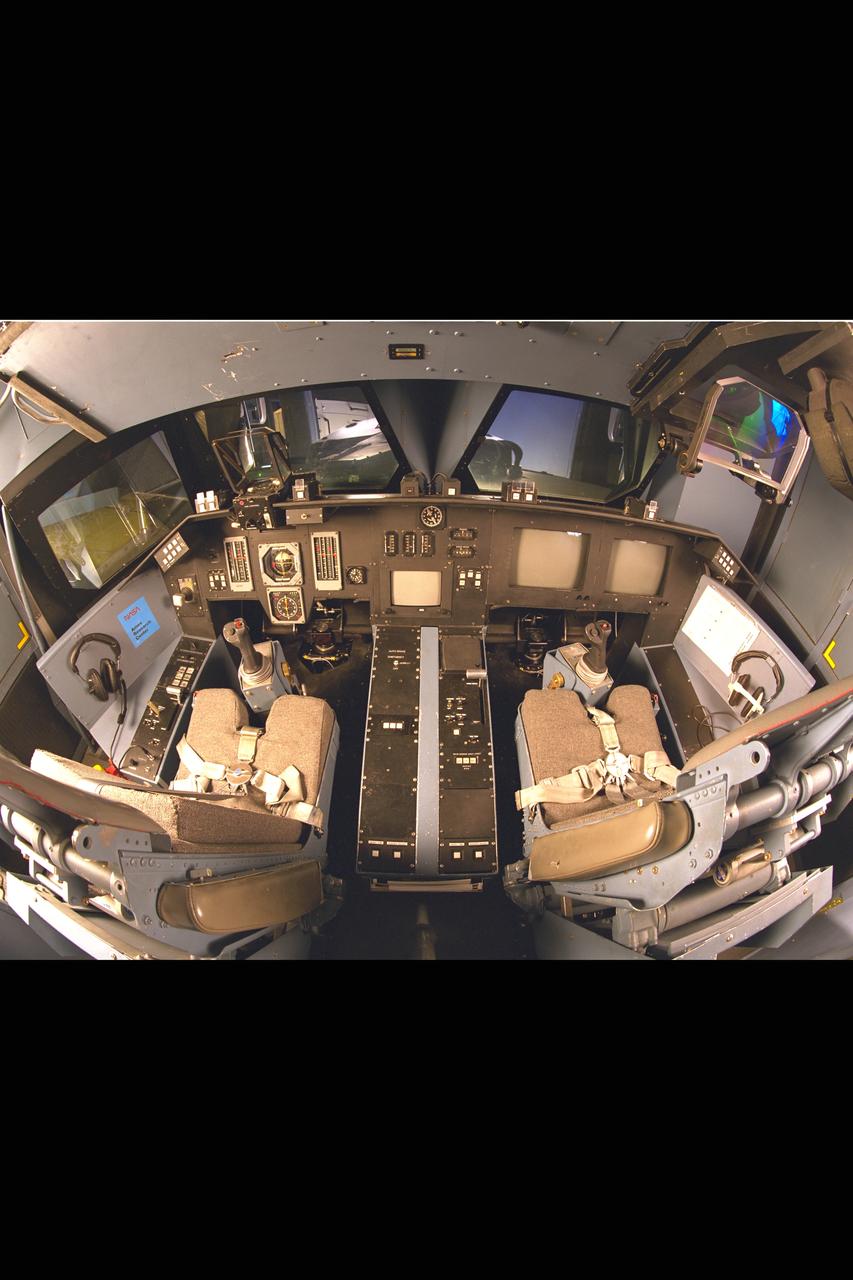
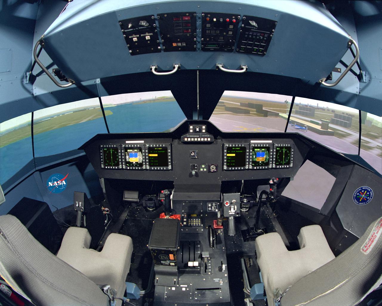
NASA Ames Vertical Motion Simulator (VMS)VMS (Vertical Motion Simulator) F-Cab interior. Overhead view of cockpit.
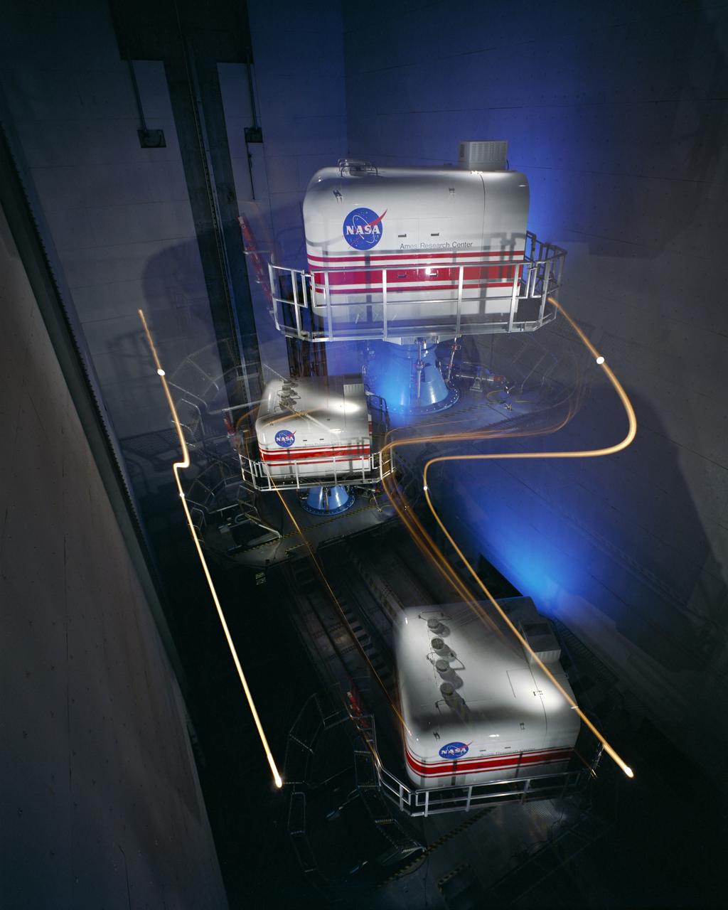
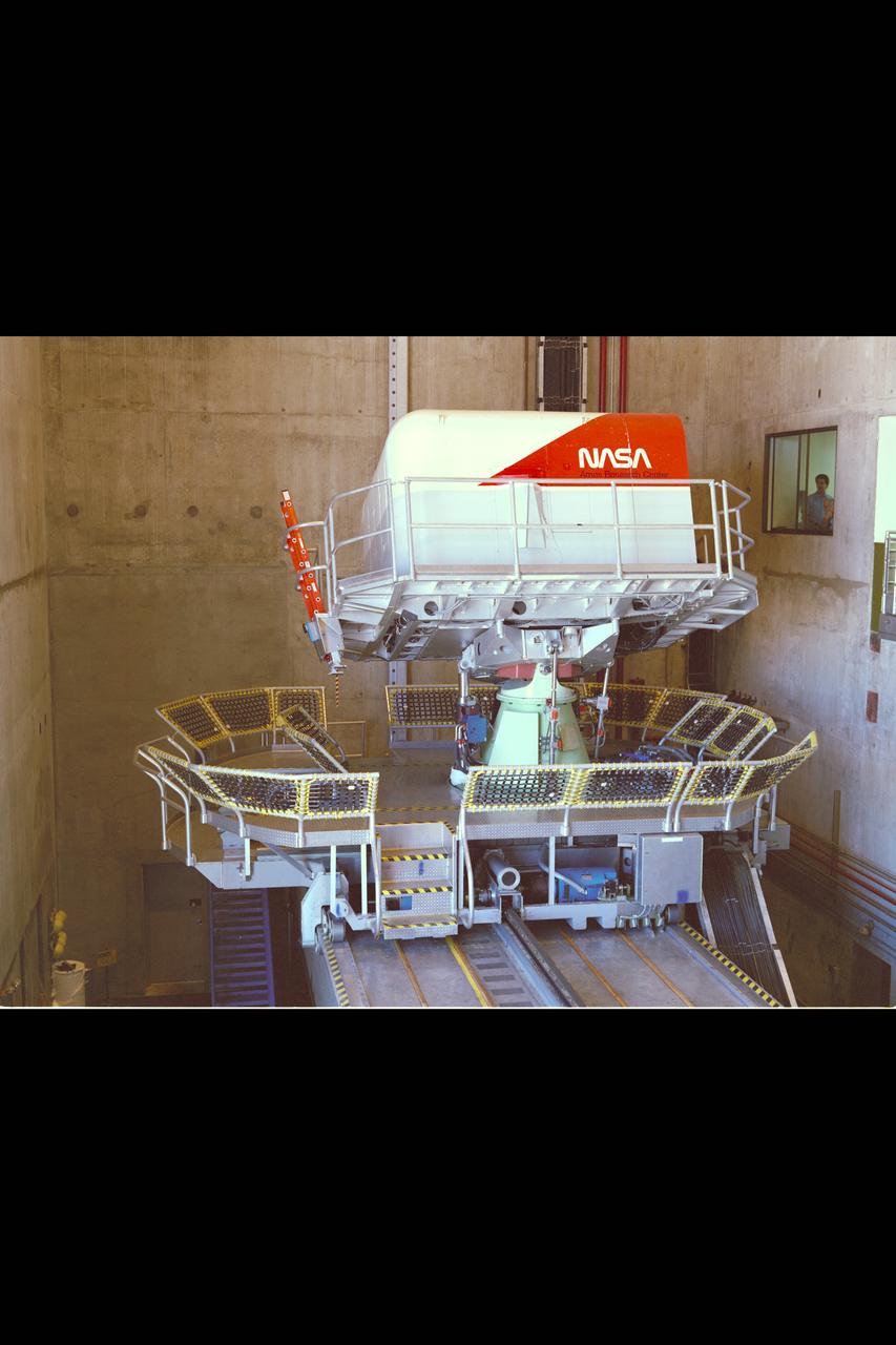
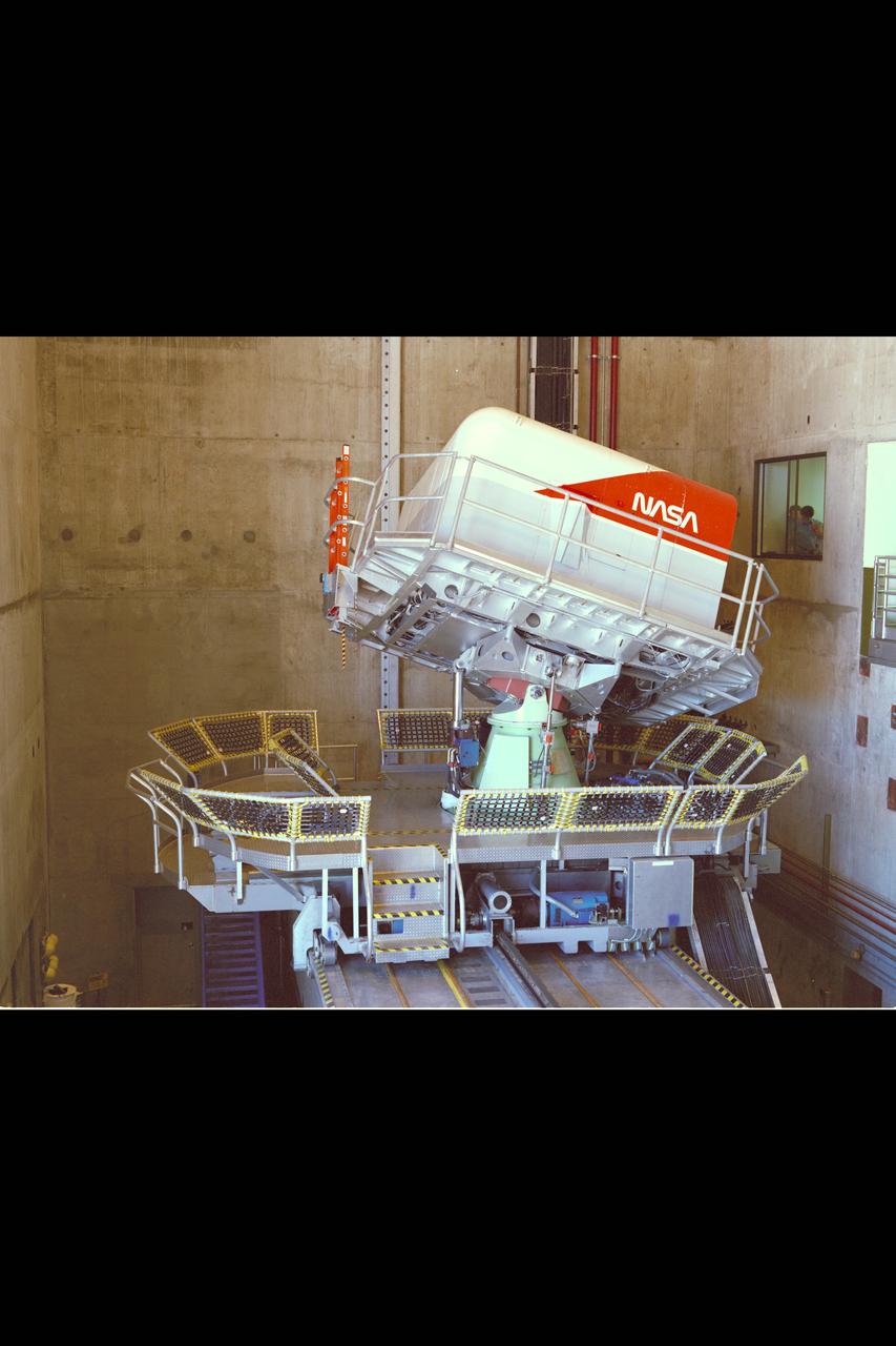
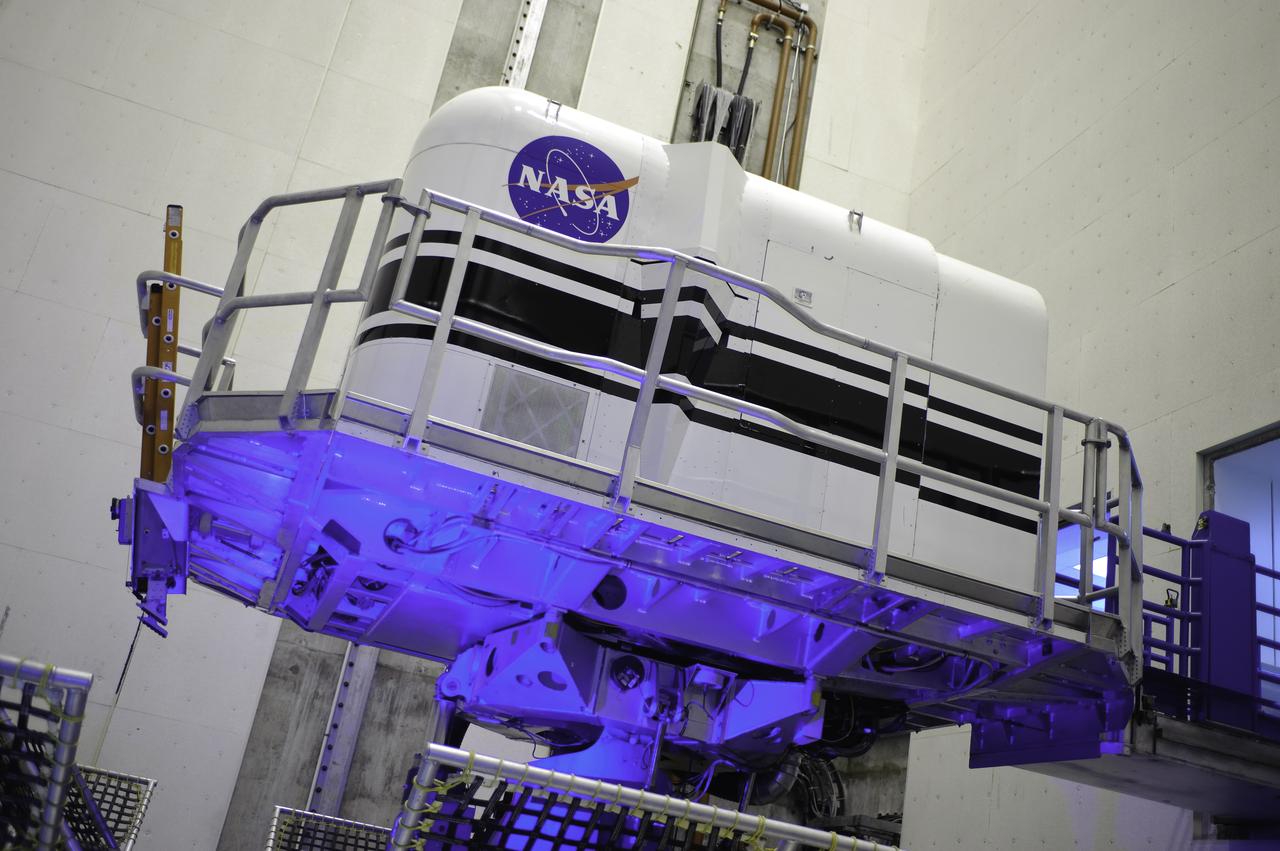
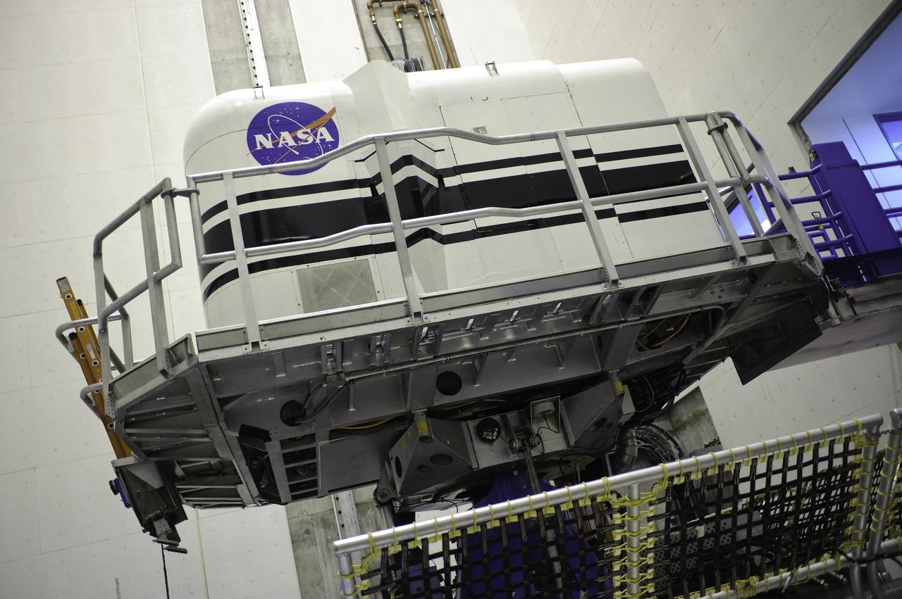
NASA Ames Bldg N-243A Vertical Motion Simulator cab in Motion in motion.
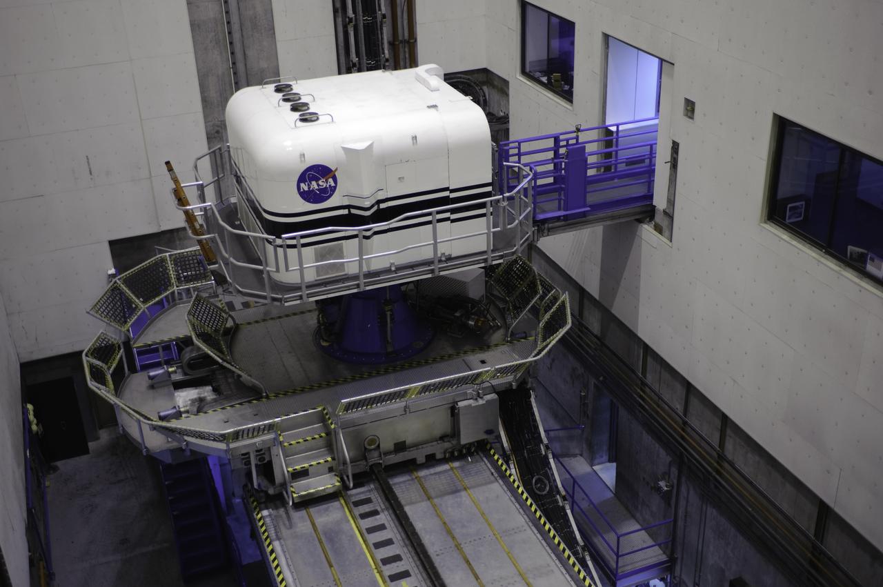
N-243A Vertical Motion Simulator
N-243A Vertical Motion Simulator
N-243A Vertical Motion Simulator
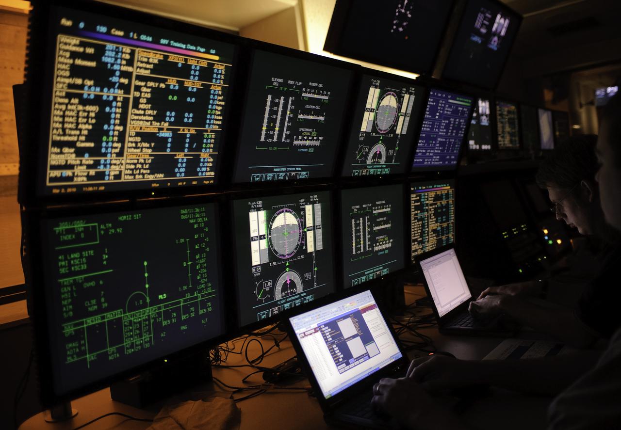
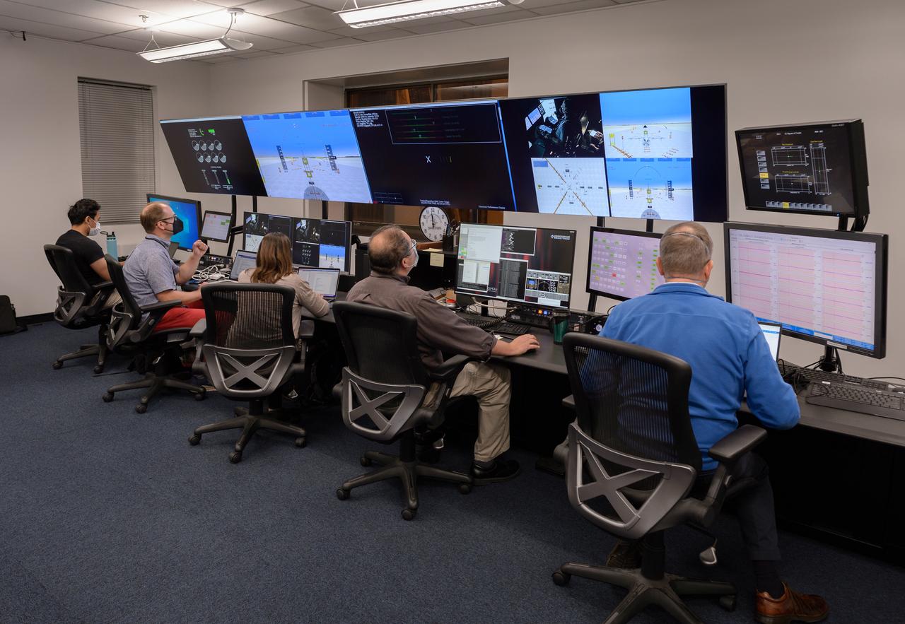
Vertical Motion Simulator (VMS) control room
Vertical Motion Simulator VMS Simulation; Rotorcraft Stability/Phase Margin in T-cab.
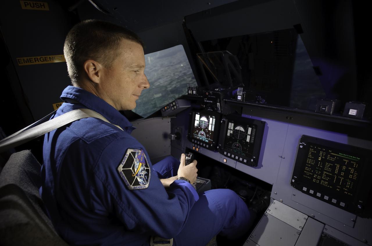
Vertical Motion Simulator (VMS) Astronaut Terry Virts flying the shuttle during simulation flight
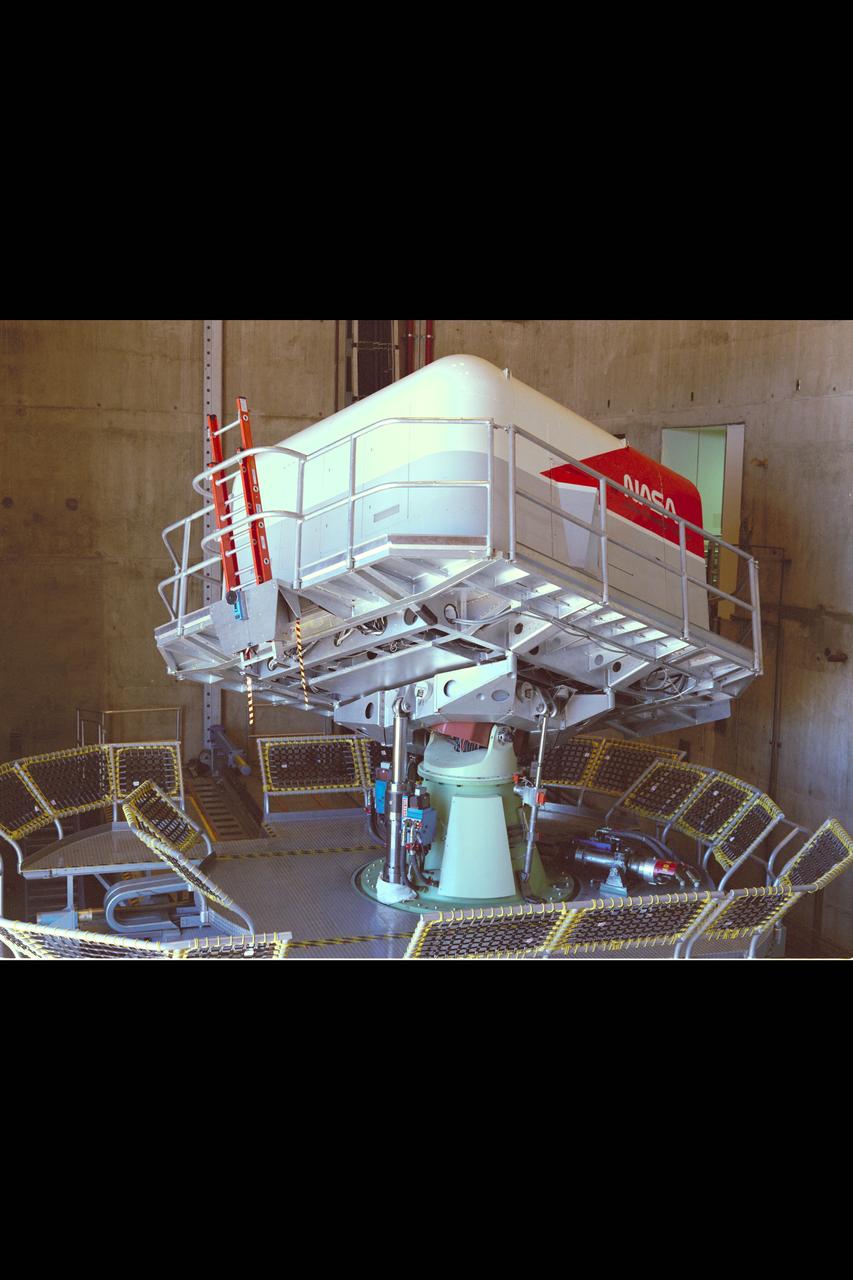
Ames Vertical Motion Simulator (VMS) T-Cab configuration
Vertical Motion Simulator (VMS) showing a Space Shuttle configuration
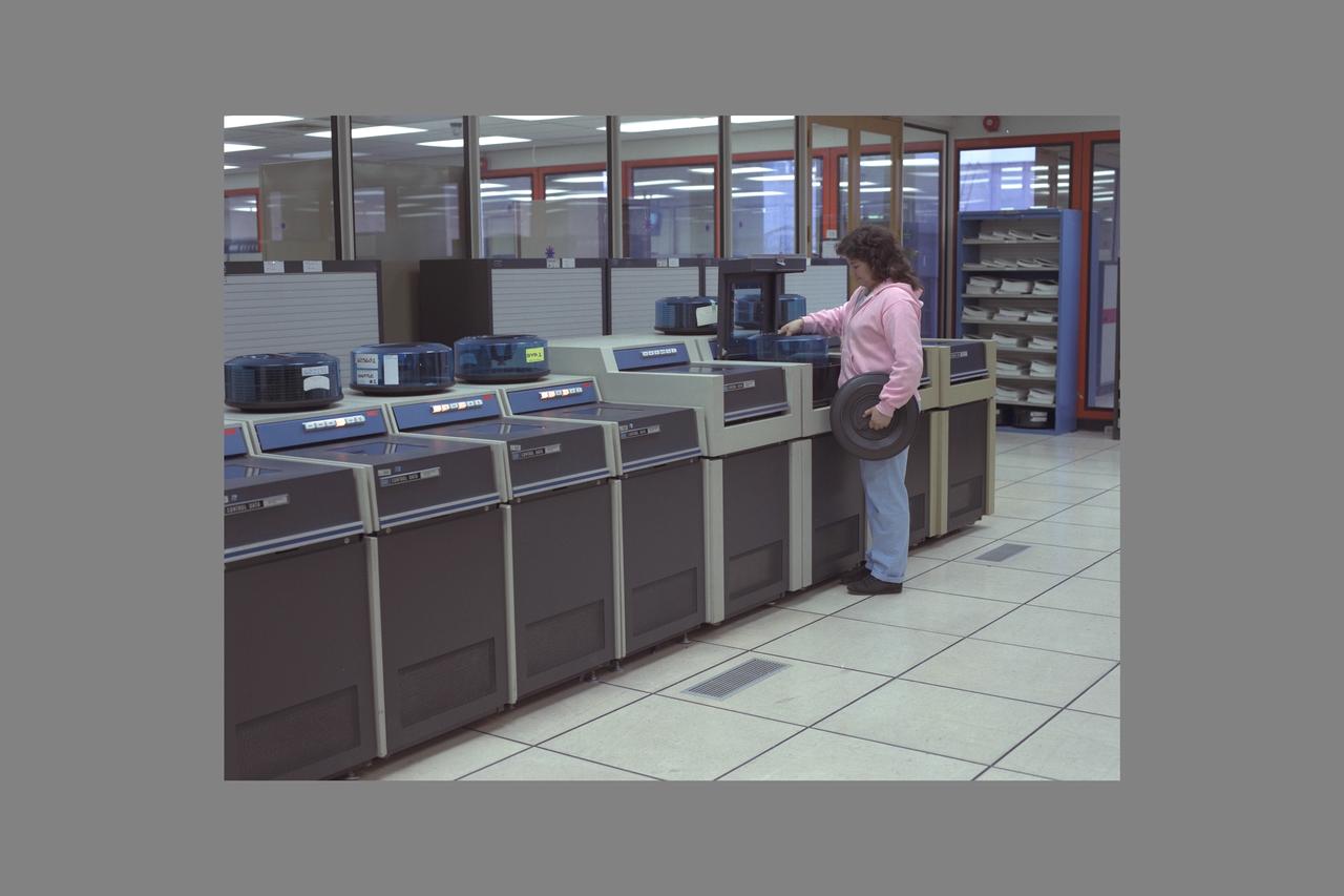
Vertical Motion Simulator VMS-7600 Computer Lab in N-243.

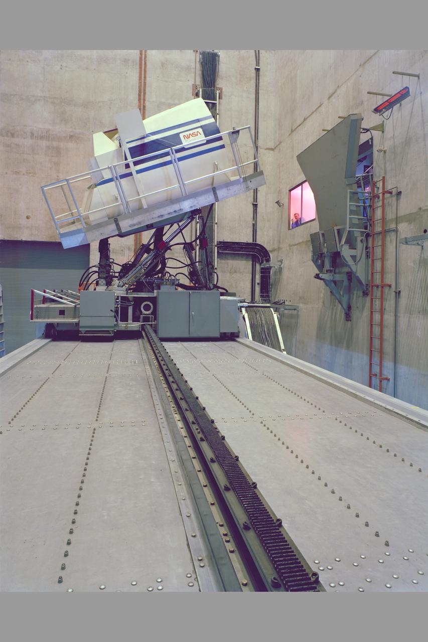
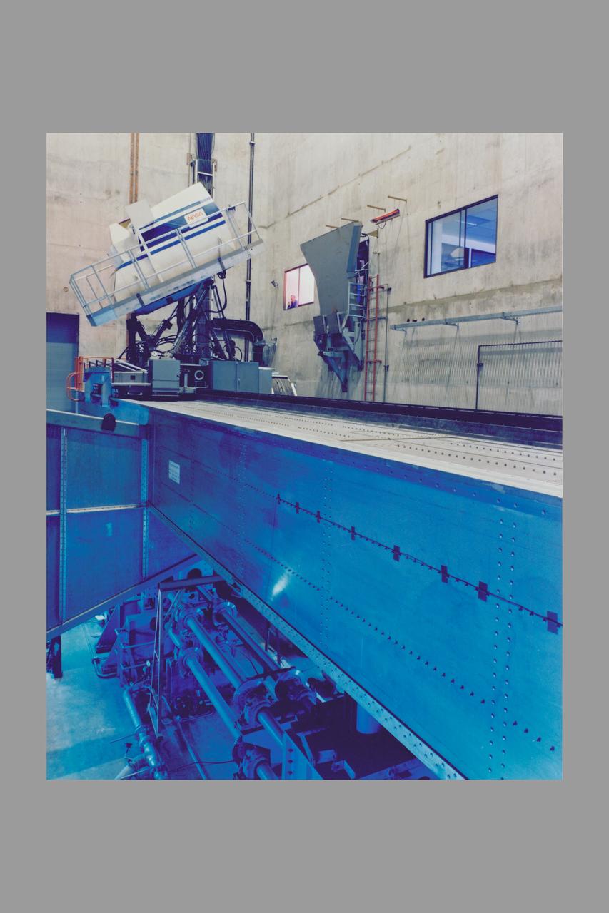
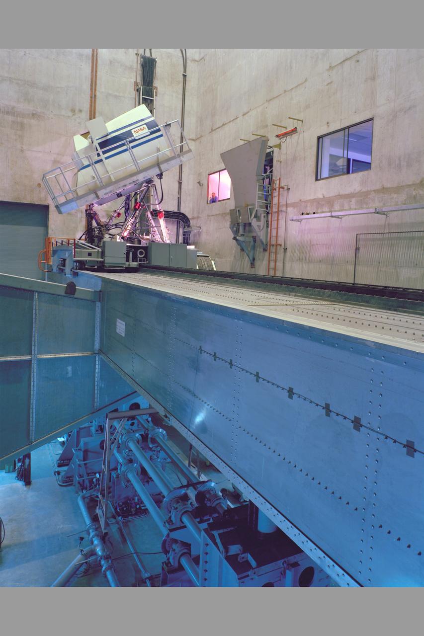
N-234A: Exterior view of the VMS (Vertical Motion Simulator) T-cab
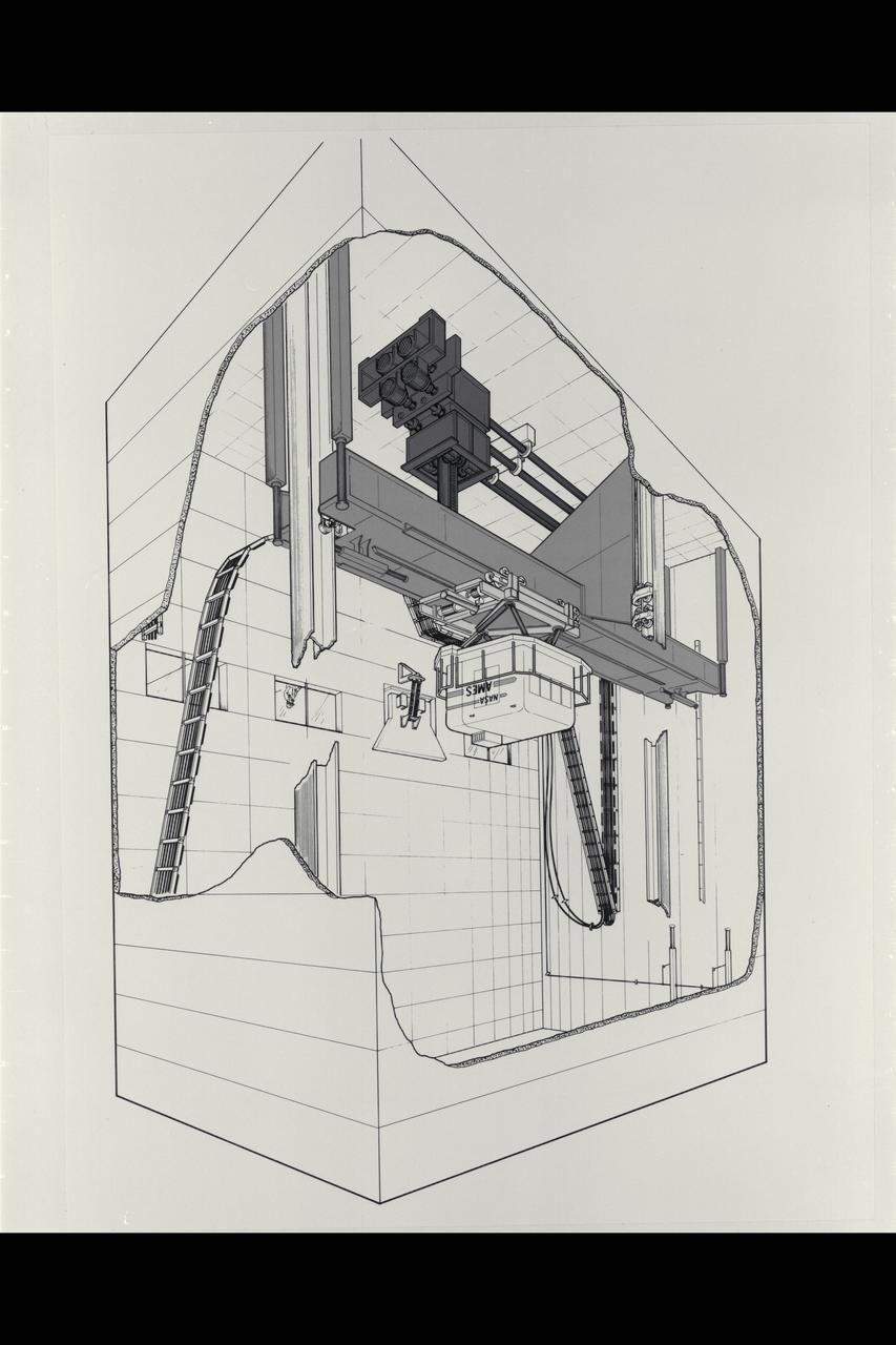
Illustration Vertical Motion Simulator (VMS) Facility and Cab cutaway
Vertical Motion Simulator (VMS) showing a Space Shuttle configuration
Ames Vertical Motion Simulator (VMS) T-Cab configuration
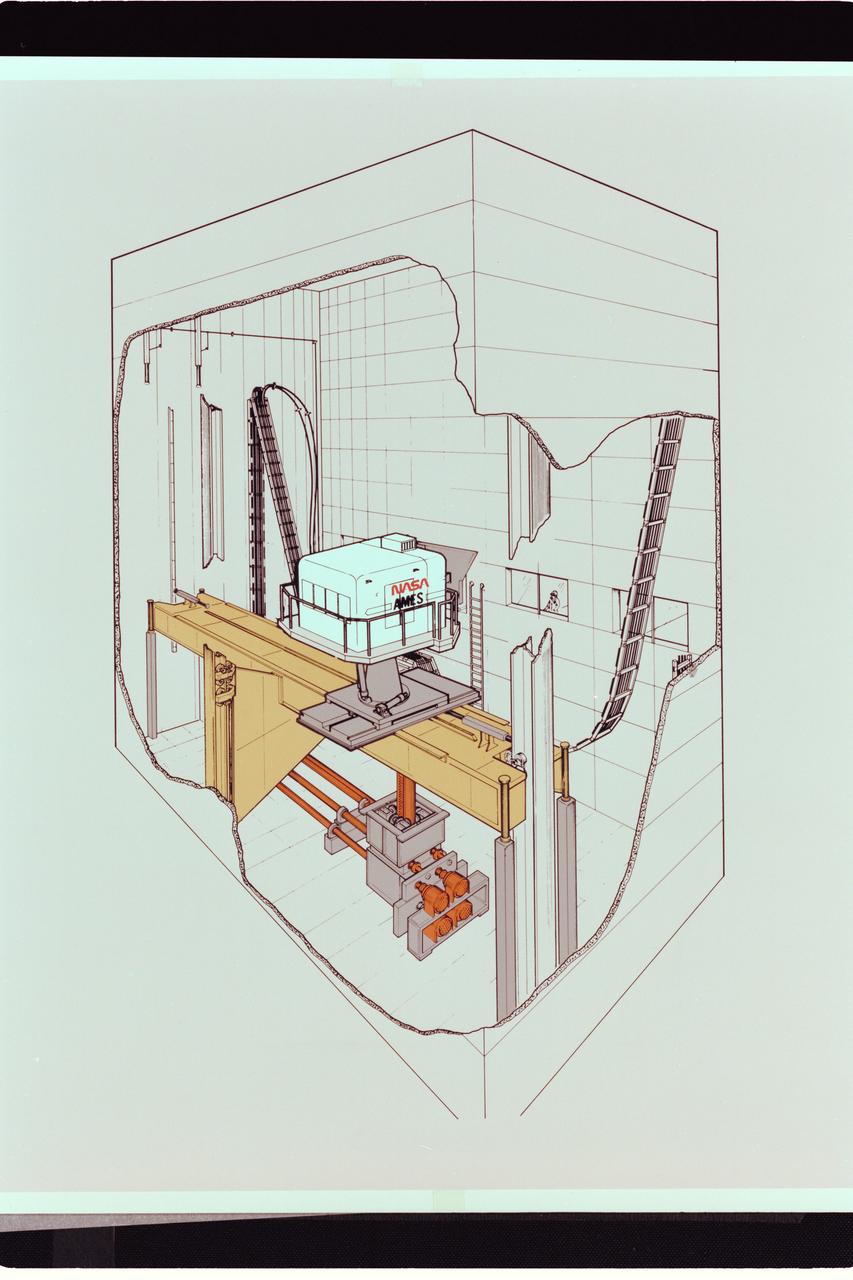
Artwork: cutaway N-243 Vertical Motion Simulator (VMS)
Ames Vertical Motion Simulator (VMS) T-Cab configuration
Vertical Motion Simulator (VMS) showing a Space Shuttle configuration
AFCM subproject simulation FAA-2 flight test team members Thomas Lombaerts, left, and Kimberlee Shish, right, in the VMS control room, N243, during a simulation.
AFCM subproject simulation FAA-2 flight test team members Allen Ruan, left, Thomas Lombaerts, Kimberlee Shish, Edgar Torres, and Stephen Norris, right, in the VMS control room, N243 during a simulation.
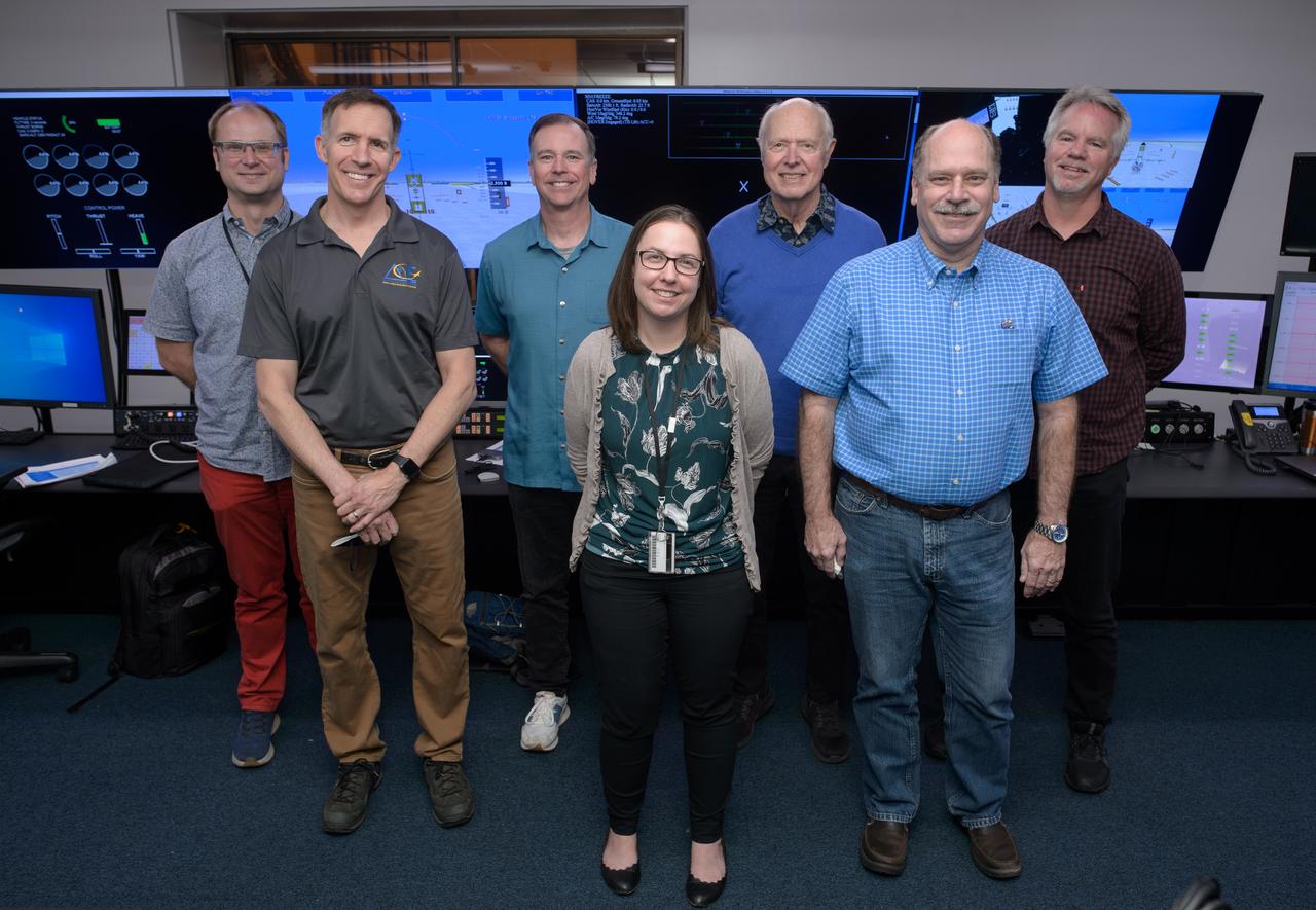
Group photo of AFCM subproject simulation FAA-2 flight test team members Thomas Lombaerts, left, Mike Feary, Dave Sizoo, Kimberlee Shish, Loran Haworth, Mitch Soth, and Dave Webber, right, in the VMS control room, N243.
AFCM subproject simulation FAA-2 flight test team member Thomas Lombaerts in the VMS control room, N243, during a simulation.
Michael Feary pilots a simulated electric vertical takeoff and landing, or eVTOL, aircraft in the VMS’s R-Cab during the AFCM subproject simulation FAA-2 flight tests in the VMS, N243.
AFCM subproject simulation FAA-2 flight test team member Thomas Lombaerts in the VMS control room, N243, during a simulation.
AFCM subproject simulation FAA-2 flight test team members Thomas Lombaerts, left, and Kimberlee Shish, right, in the VMS control room, N243, during a simulation.
AFCM subproject simulation FAA-2 flight test team members Allen Ruan, left, Thomas Lombaerts, Kimberlee Shish, Edgar Torres, and Stephen Norris, right, in the VMS control room, N243 during a simulation.
AFCM subproject simulation FAA-2 flight test team members Allen Ruan, left, Thomas Lombaerts, and Kimberlee Shish, right, in the VMS control room, N243, during a simulation.

AFCM subproject simulation FAA-2 flight test team members Allen Ruan, left, Thomas Lombaerts, and Kimberlee Shish, right, in the VMS control room, N243, during a simulation.
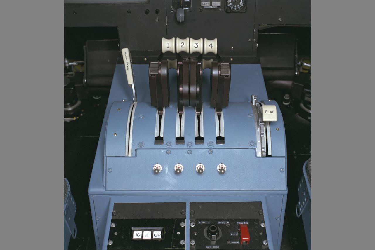
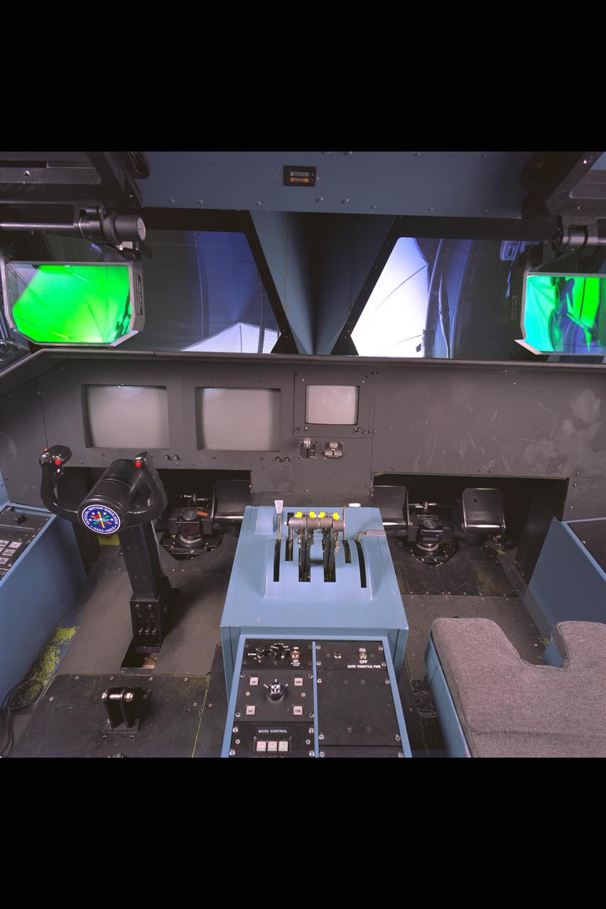
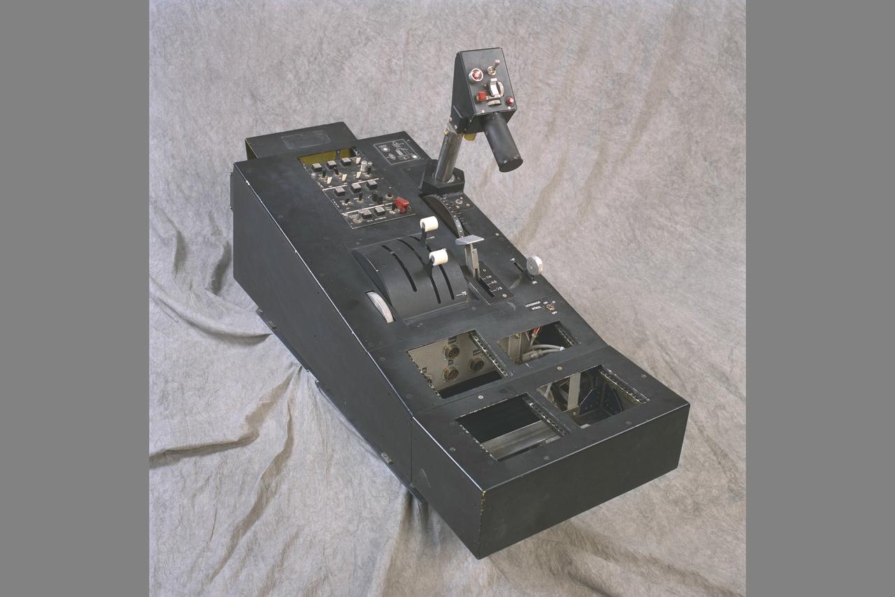
N-243 NASA Ames VMS (Vertical Motion simulator) S-Cab: HSCT (High Speed Civil Transport) Simulation Throttles
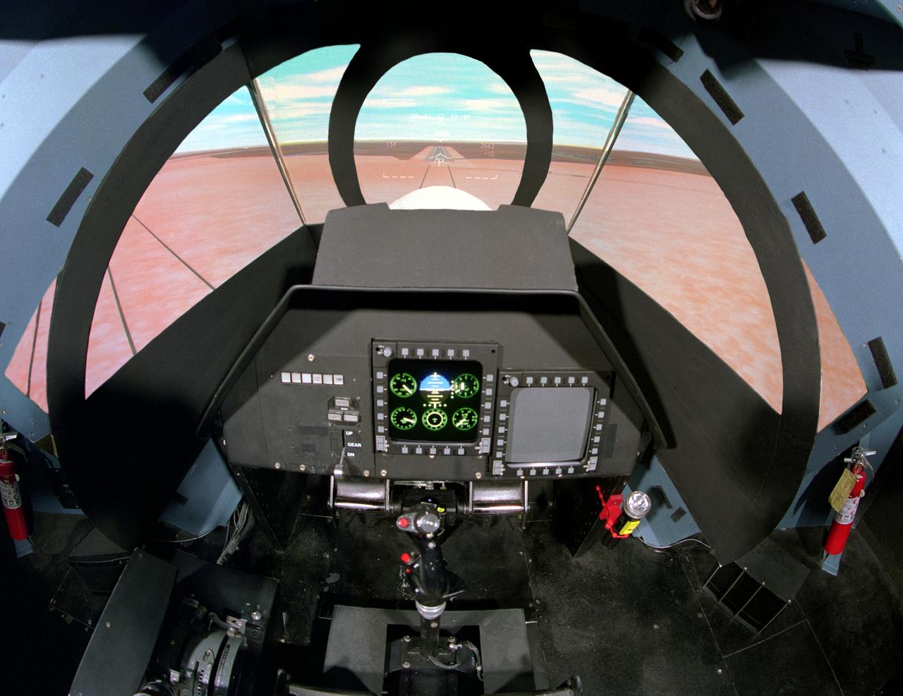
NASA Ames Vertical Motion Simulator (VMS): F-cab SIMFR (Simulation Frequency Response) Project; Pilots cockpit and out-the-window (OTW) view
Vertical Motion Simulator VMS Simulation; Rotorcraft Stability/Phase Margin in T-cab. out the window panorama - overall cab view
Vertical Motion Simulator VMS Simulation; Rotorcraft Stability/Phase Margin in T-cab. Out-the-window (otw) panorama views from pilots point of view
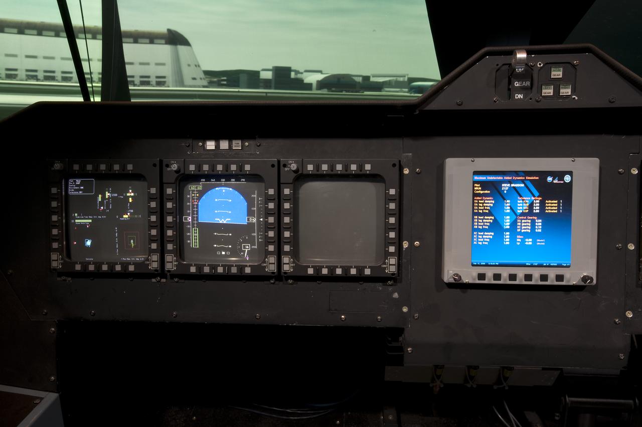
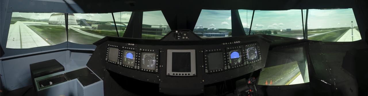
NASA Ames VMS (Vertical Motion simulator) S-Cab: Cockpit, Control Panel and heads-up displays
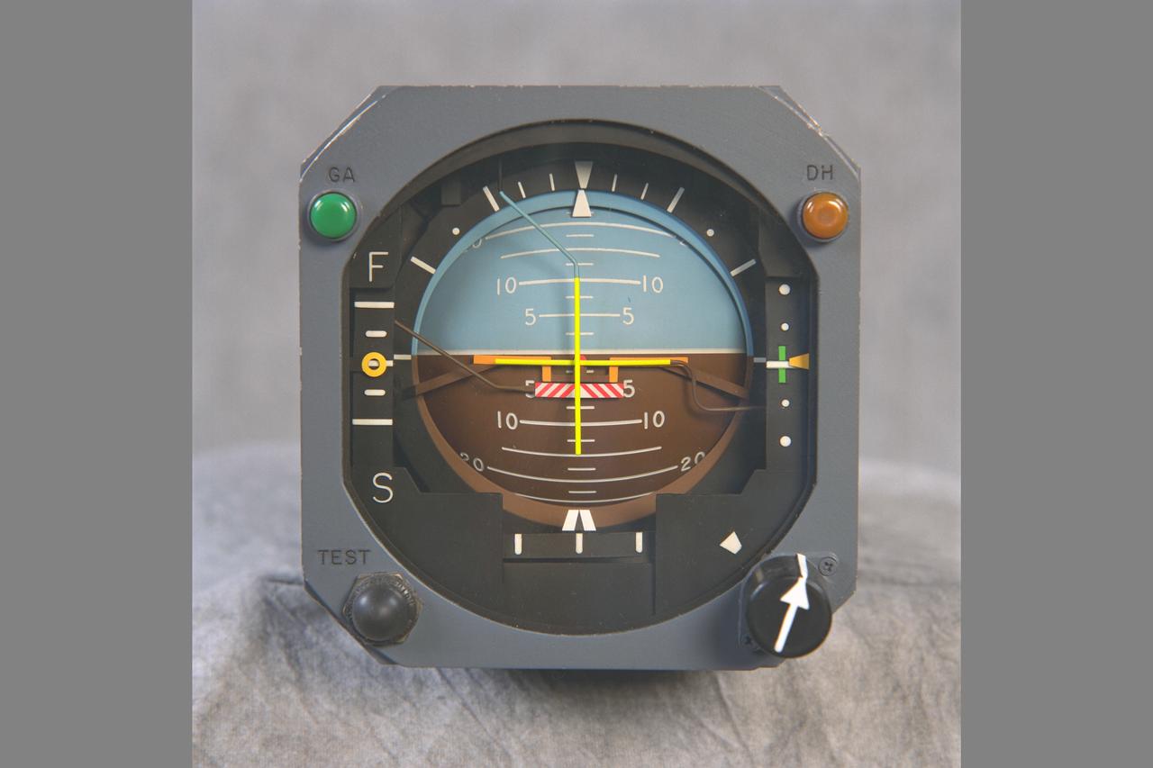
ARTIFICIAL HORIZON gage used in the NASA Ames VMS: S-CAB, (Vertical Motion Simulator).
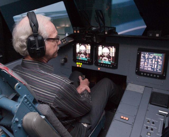
Capt. Chesley 'Sully' Sullenberger visits Ames Vertical Motion Simulator facility and takes a 'ride' in the Shuttle Cab (S-cab).

Capt. Chesley 'Sully' Sullenberger visits Ames Vertical Motion Simulator facility and takes a 'ride' in the Shuttle Cab (S-cab).
Capt. Chesley 'Sully' Sullenberger visits Ames Vertical Motion Simulator facility and takes a 'ride' in the Shuttle Cab (S-cab).
Vertical Motion Simulator (VMS) interior with Shuttle Cab (S-cab) mounted in facility.
Capt. Chesley 'Sully' Sullenberger visits Ames Vertical Motion Simulator facility and takes a 'ride' in the Shuttle Cab (S-cab).
NASA Ames VMS (Vertical Motion Simulator): S-CAB, THROTTLE CONSOLE studio shoot
ROTOCRAFT CONSOLE. NASA Ames VMS: S-CAB, (Vertical Motion Simulator). studio shot
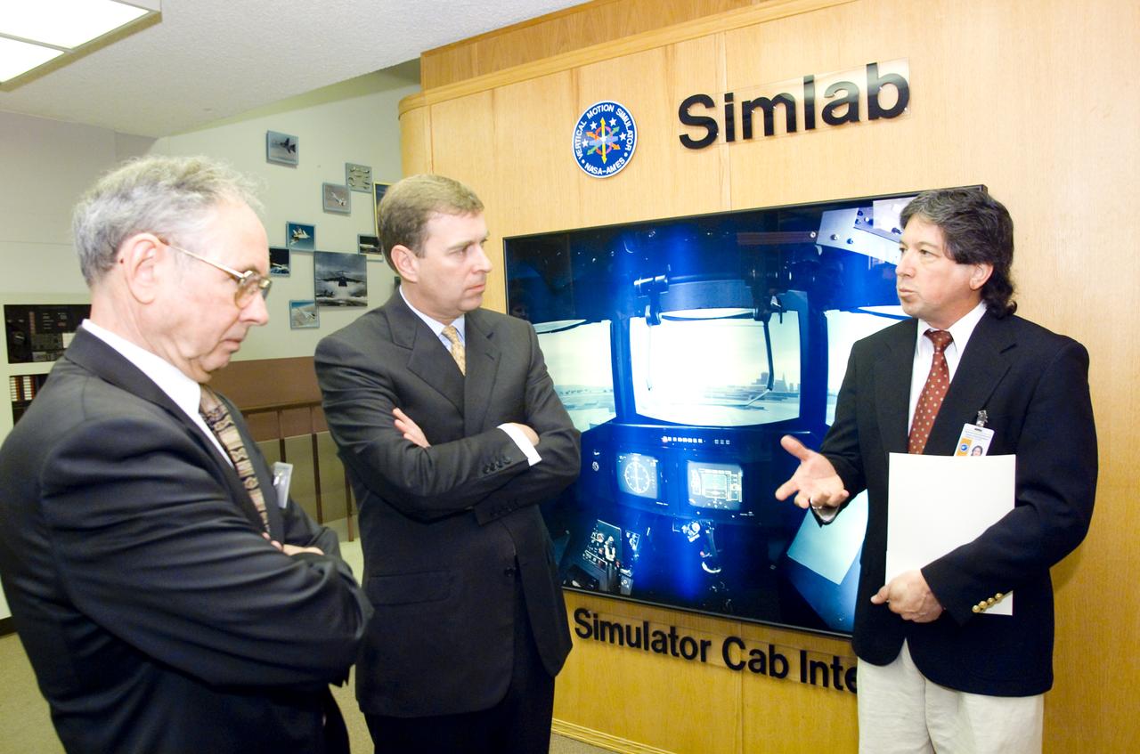
British royalty visits Ames; Prince Andrew, Duke of York on tour of Vertical Motion Simulator Facilities (VMS)
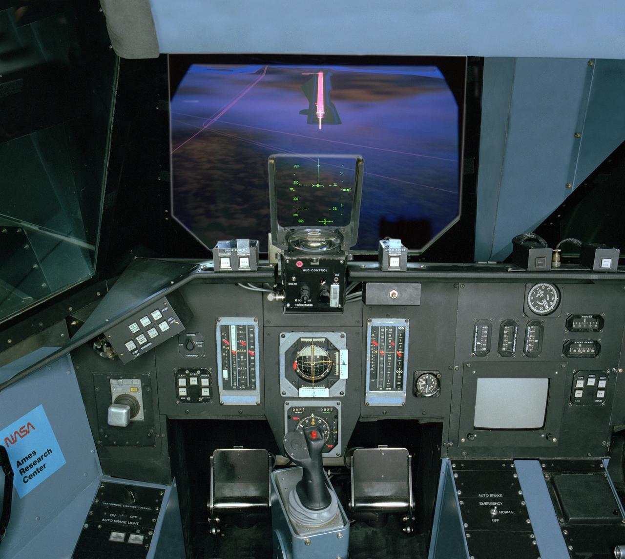
NASA Ames VMS (Vertical Motion simulator) S-cab Space Shuttle sim with out the window views 'night landing'
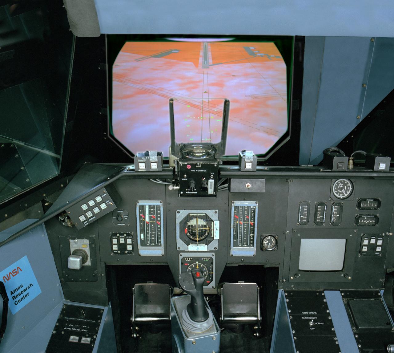
NASA Ames VMS (Vertical Motion simulator) S-cab Space Shuttle sim with out the window views 'DFRC landing'
NASA Ames Vertical Motion Simulator (VMS); T-Cab Civil Tilt Rotor Project (CTR) project cab configuration
NASA Ames VMS (Vertical Motion Simulator) S-Cab (Space Shuttle Cab) overhead fisheye view
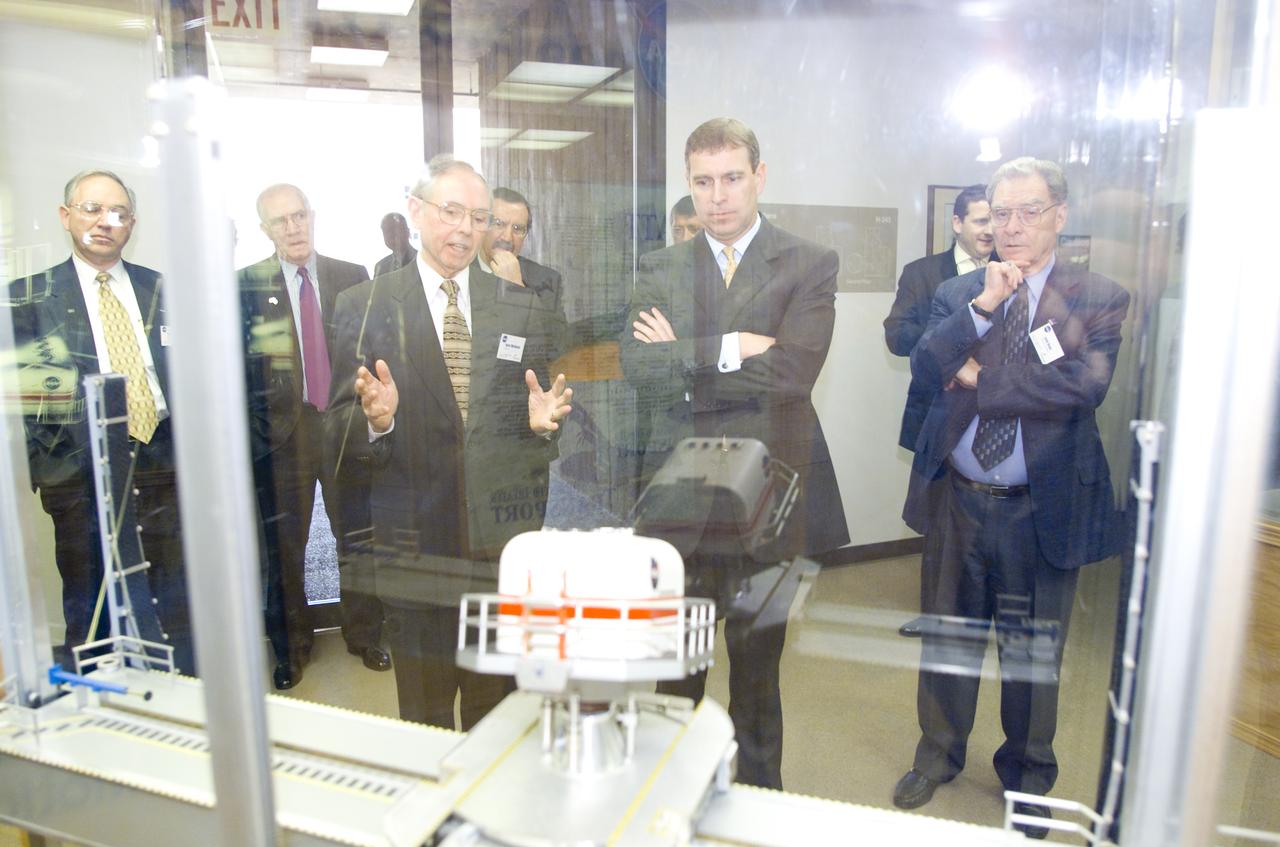
British royalty visits Ames; Prince Andrew, Duke of York on tour at the VMS (Vertical Motion Simulator)
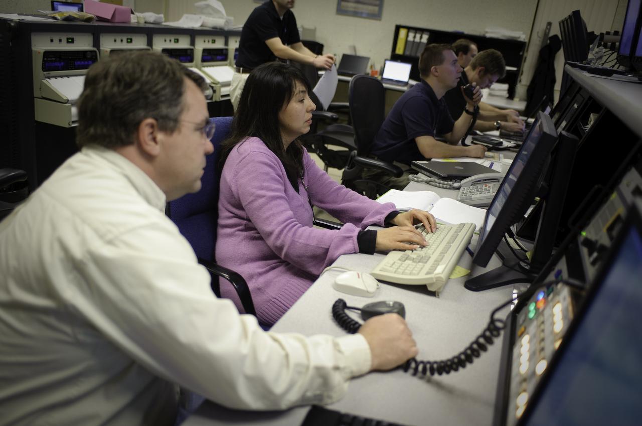
Vertical Motion Simulator (VMS) control room with Steve Beard and Estela Hernandez-Buchmann
Vertical Motion Simulator (VMS) interior with Shuttle Cab (S-cab) mounted in facility.
Vertical Motion Simulator (VMS) interior with Shuttle Cab (S-cab) mounted in facility.
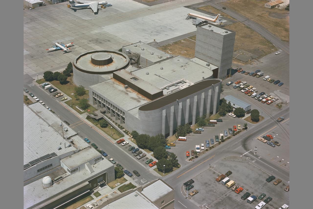
Aerial of Ames: N-243 (Flight and Guidance Simulation Laboratory) and N-243A (Simulation Equipment) houses the Vertical Motion Simulator (VMS) and the Crew Station Research Development Facility (CSRDF)
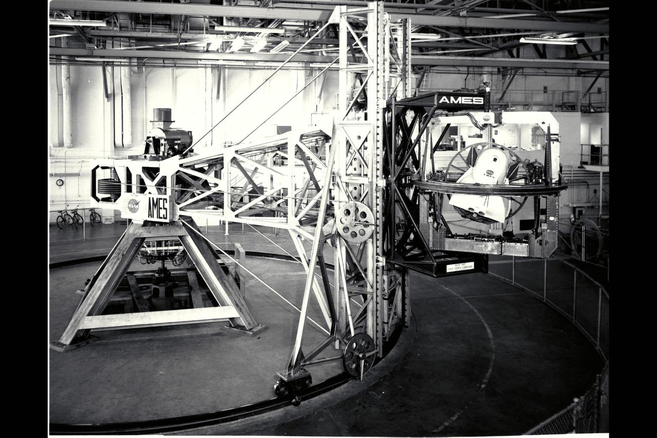
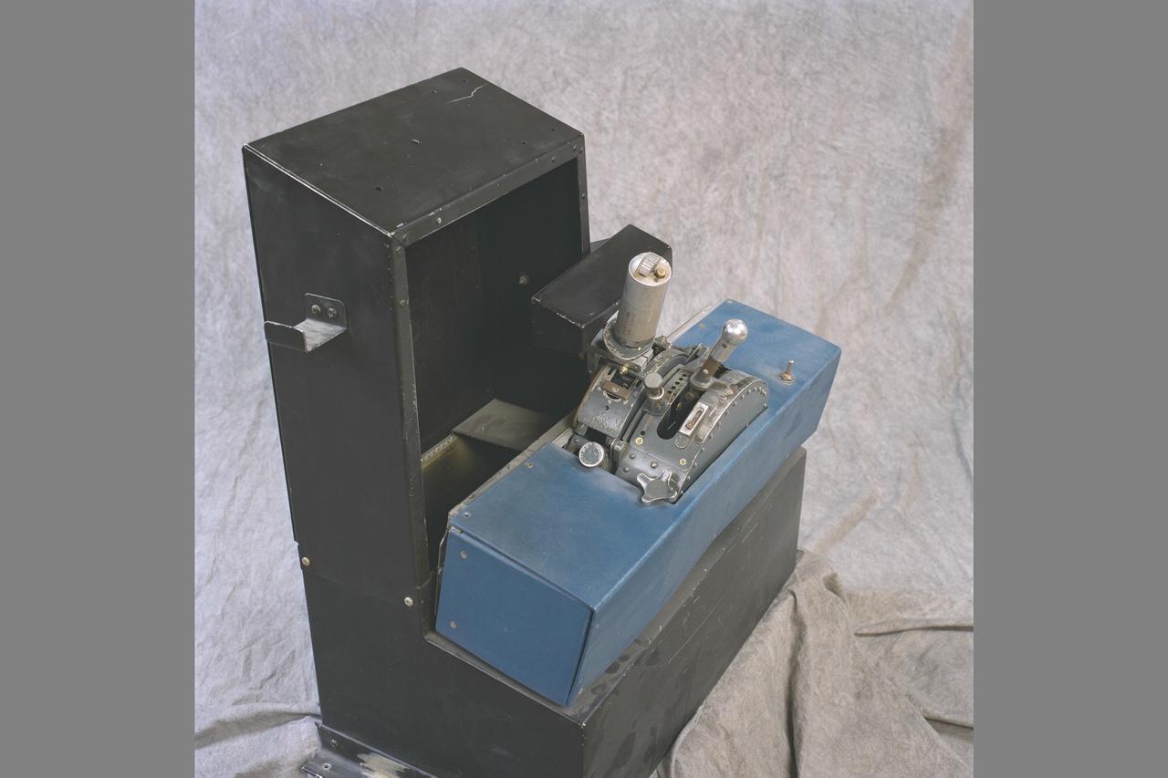
Ames 5 degrees-of-freedom motion simulator: This simulator incorporated a centrifuge of 30ft radius. The simulatored cockpit, located intn a hooded cab at the end of the centrifuge arm, was driven by motors, as required by the simulation, about each of its three axes (itch, roll, and yaw). The cab was also driven through a limited range of motion along the vertical axis and of course was driven by the centrifuge arm along a curved path of fixed radius in the horizontal plane. Thus the motions that could be simulated i the cab were three angular motions, one translational motion, and a curvilinear combination of the remaining two translational motions. The curvilinear motions, and associated accelerations, were, of course, fairly representative of airplane flight. The simulator was placed in operation early in 1961. ref: Adventures in Research (pg 341/341) NASA SP-4302
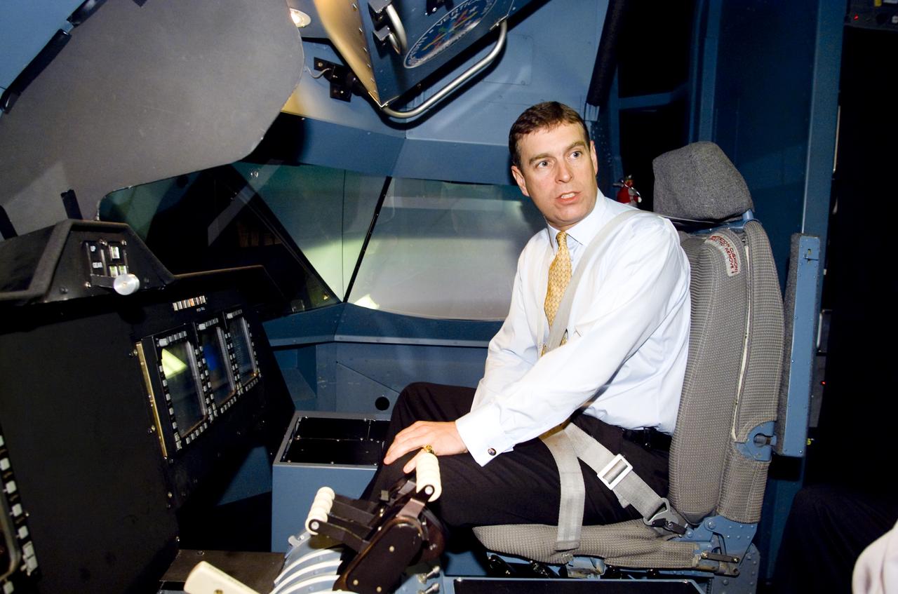
British Royalty visits Ames; Prince Andrew, Duke of York on tour. Seen here in the Vertical Motion Simulator in N-243 flying a tilt-wing simulation. (VMS)
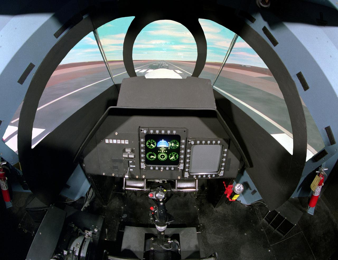
NASA Ames Vertical Motion Simulator (VMS)VMS: F-cab SIMFR (Simulation Frequency Response) Project; Pilots cockpit and out-th-window (OTW) view
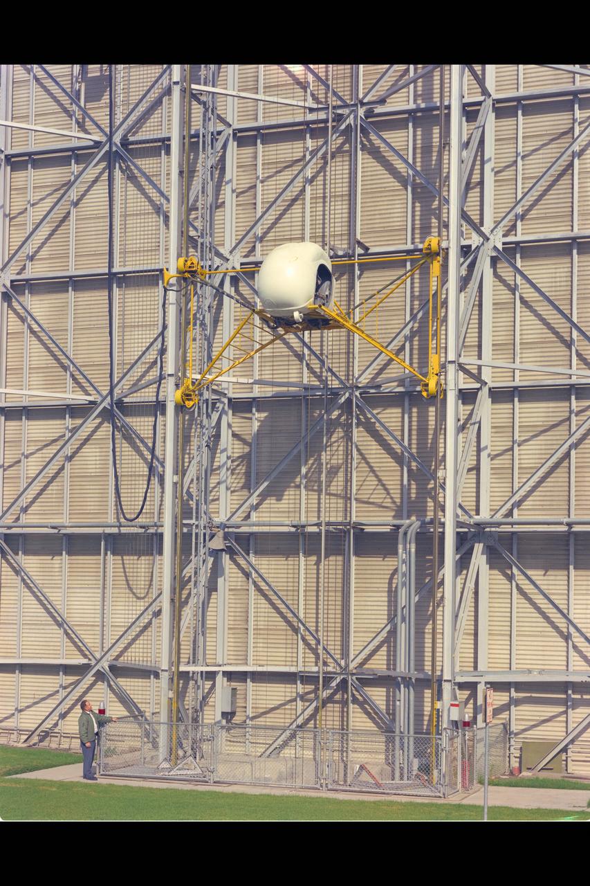
Height-Control Test Apparatus (HICONTA) Simulator mounted to the exterior of the 40x80ft W.T. Building N-221B and provided extensive vertical motion simulating airplanes, helicopter and V/STOL aircraft
NASA Ames Vertical Motion Simulator (VMS); T-Cab Civil Tilt Rotor Project (CTR) OTW (out the window) composite views
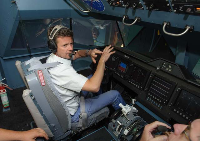
HRH Prince Frederik of Denmark visit and tour of NASA Ames Research Center. shown here at the Vertical Motion Simulator in the cockpit flying a sim.
NASA Ames Vertical Motion Simulator (VMS); T-Cab Civil Tilt Rotor Project (CTR) OTW (out the window) composite views
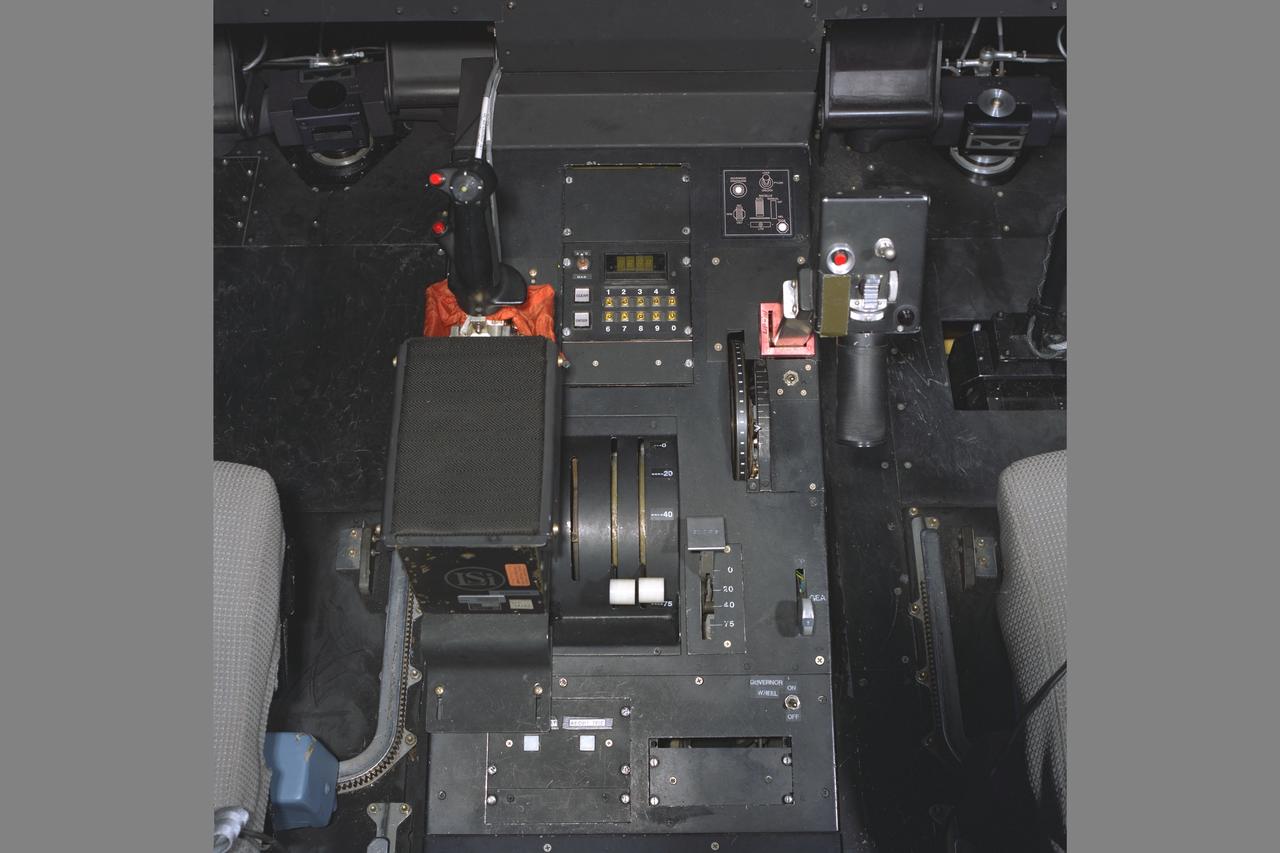
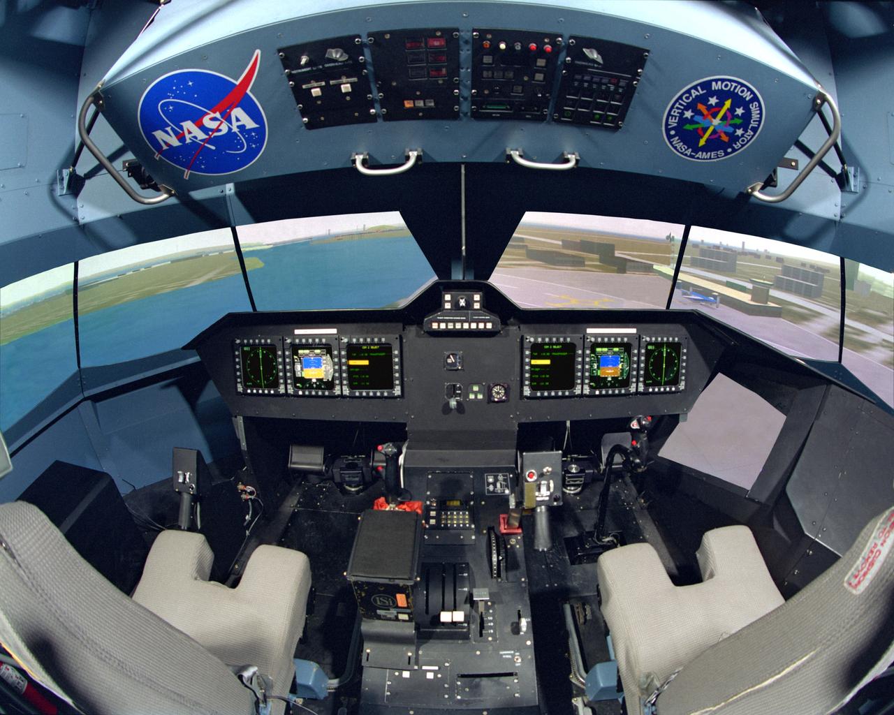
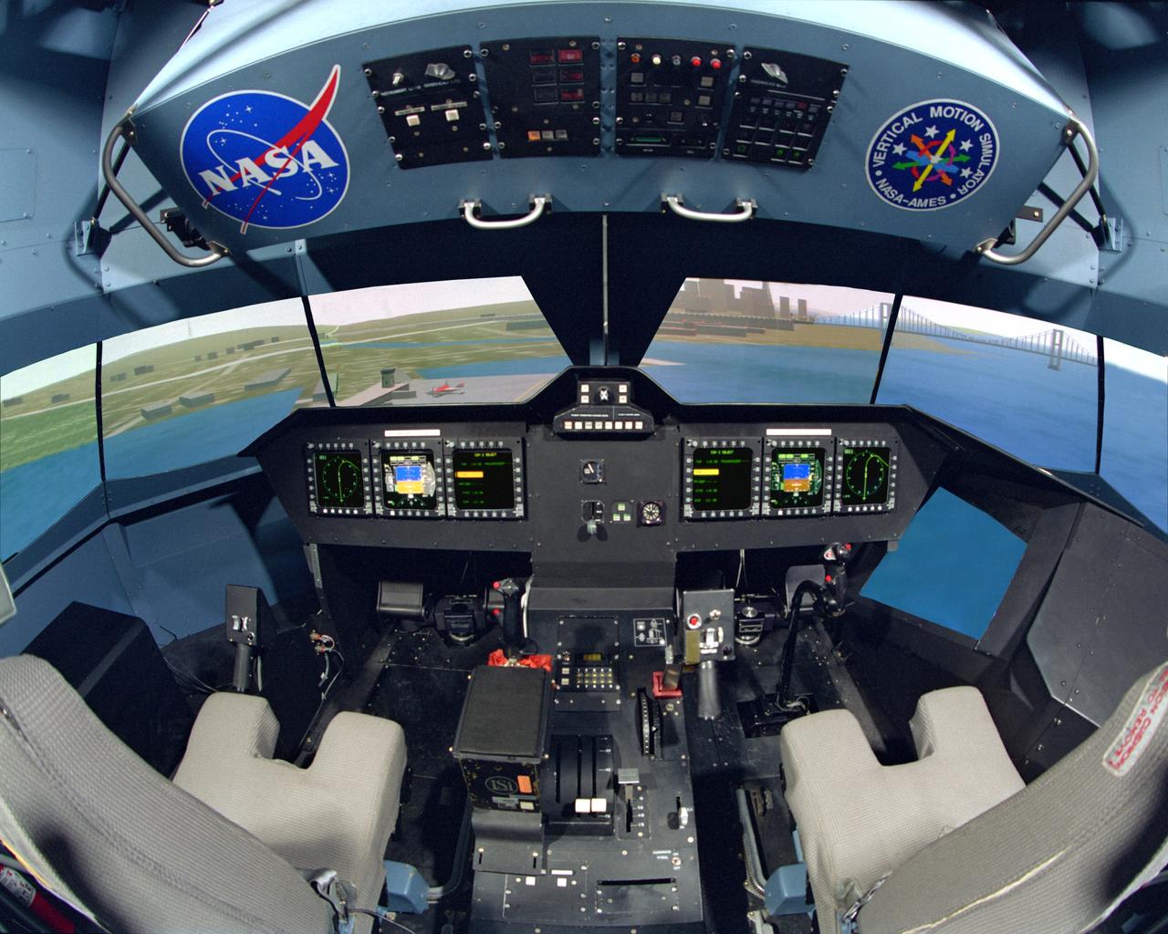
NASA Ames Vertical Motion Simulator (VMS); T-Cab Civil Tilt Rotor Project (CTR) project cab configuration with center console
NASA Ames Vertical Motion Simulator (VMS); T-Cab Civil Tilt Rotor Project (CTR) OTW (out the window) composite views
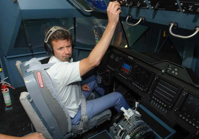
HRH Prince Frederik of Denmark visit and tour of NASA Ames Research Center. shown here at the Vertical Motion Simulator in the cockpit flying a sim.
NASA AA - Associate Administrator for Aeronautics Jai Shin visits Ames Research Center and tours the Vertical Motion Simulator (VMS, T-cab) Jaiwon Shin, Moffett Field Hangar 1 shows in the VMS visual scene.

Vice President Mike Pence right center, chatting with Jim Bridenstein, left, Tony Colaprete. left center and Dan Andrews, right in front of the VIPER robot at the Vertical Motion Simulator (VMS).
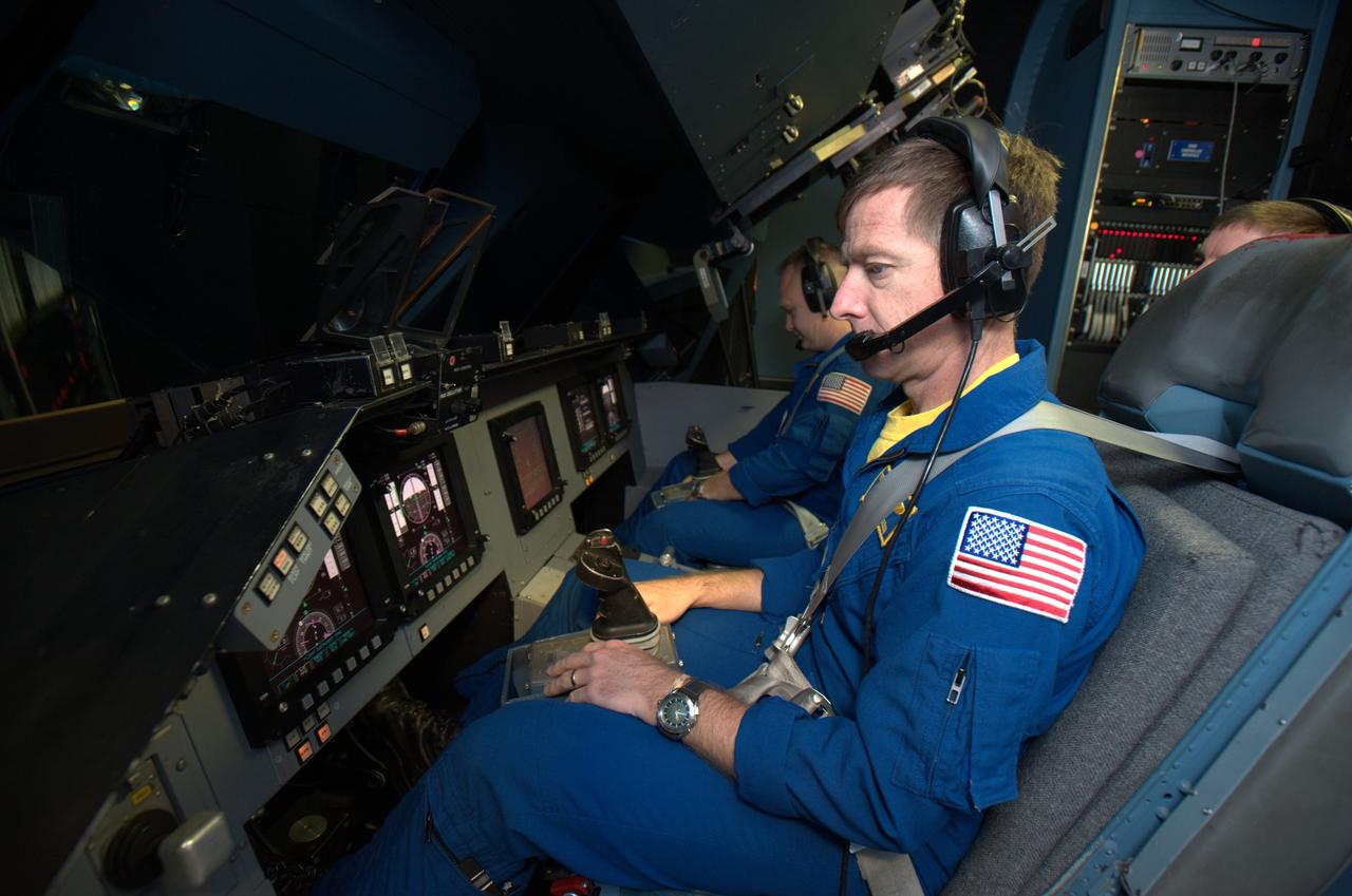
STS-135 astronaut training in the Vertical Motion Simulator, Ames Research Center, Moffett Field, CA. Mission Chris Ferguson commander in forground, Doug Hurley, pilot in background are in VMS S-cab cockpit for simulated landing practice under a variety of landing sites and conditions.
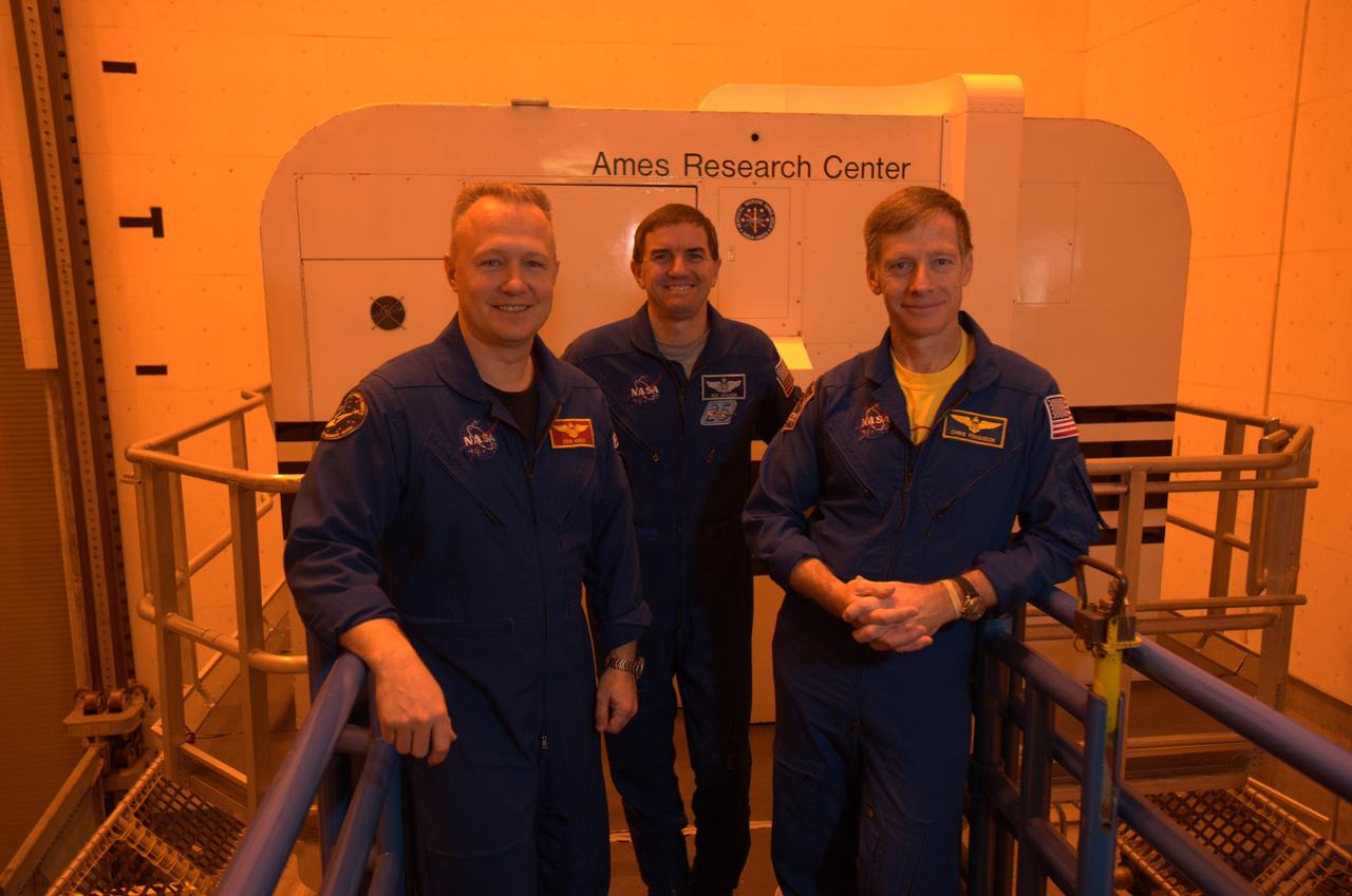
STS-135 astronaut training in the Vertical Motion Simulator, Ames Research Center, Moffett Field, CA. From left to right are Doug Hurley, pilot for mission, Rex Walheim, mission specialist and Chris Ferguson, mission commander outside of the S-cab in the VMS facility.
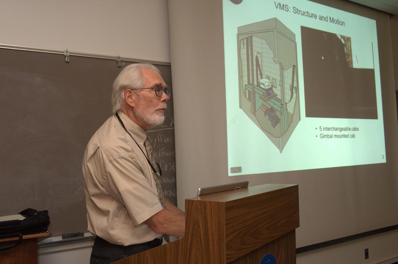
Aeroanutics Technical Seminar series: Pilot Force Measurement with Inertia and Gravity Compensation by Rodger A. Mueller (offering an interesting behind-the-scenes look at some of the research that goes into creating high-fedelity, pilot-control loader simulation experiences for pilots and astronauts using the world renowned NASA Ames Vertical Motion Simulator) Series audio on file in Ames Library
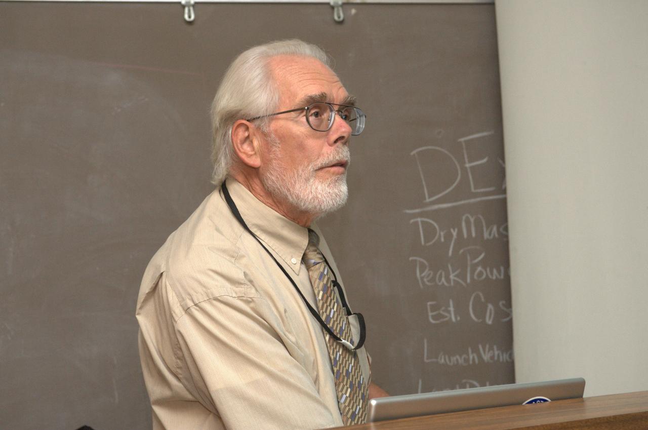
Aeroanutics Technical Seminar series: Pilot Force Measurement with Inertia and Gravity Compensation by Rodger A. Mueller (offering an interesting behind-the-scenes look at some of the research that goes into creating high-fedelity, pilot-control loader simulation experiences for pilots and astronauts using the world renowned NASA Ames Vertical Motion Simulator) Series audio on file in Ames Library
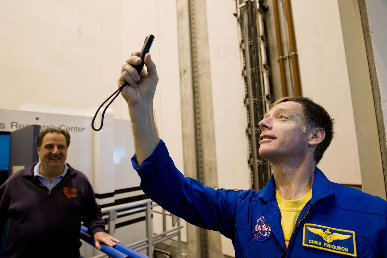
JSC2011-E-040195 (2 March 2011) --- NASA astronaut Chris Ferguson, STS-135 commander, takes photos of the massive Vertical Motion Simulator (VMS) at NASA's AMES Research Center before the crew trains in the simulator on Wednesday, March 2, 2011, in Mountain View, Calif. Photo credit: NASA Photo/Houston Chronicle, Smiley N. Pool
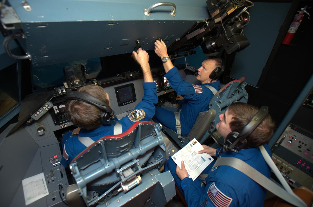
STS-135 astronaut training in the Vertical Motion Simulator, Ames Research Center, Moffett Field, CA. In this overhead view are Chris Ferguson commander on right, Doug Hurley, pilot on left and Rex Walheim, mission specialist, center back are in VMS S-cab cockpit for simulated landing practice under a variety of landing sites and conditions.
JSC2011-E-040201 (2 March 2011) --- NASA astronaut Doug Hurley pilots a simulated landing at the Kennedy Space Center as the STS-135 crew trains in the Vertical Motion Simulator (VMS) at NASA's Ames Research Center in Mountain View, Calif. on March 2, 2011. Photo credit: NASA Photo/Houston Chronicle, Smiley N. Pool
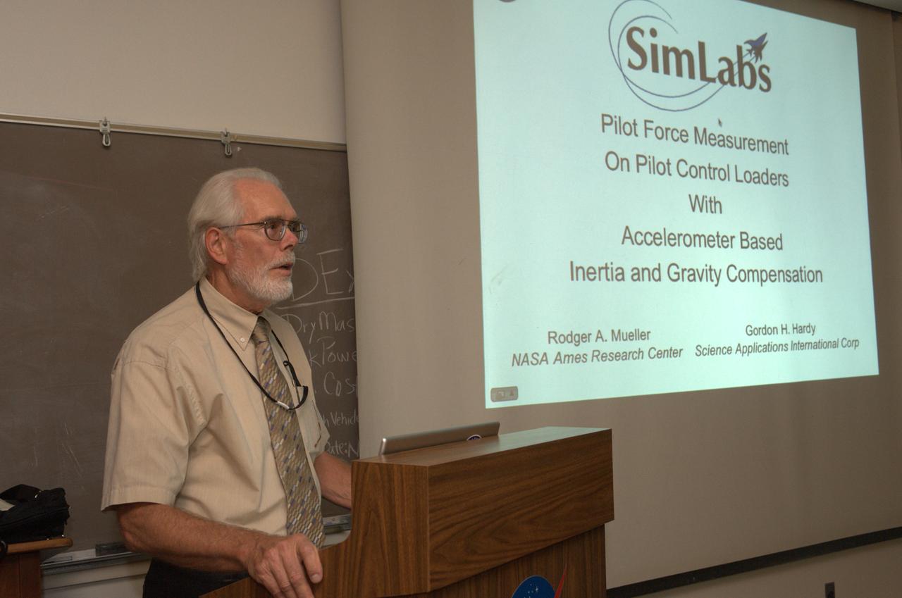
Aeronautics Technical Seminar series: Pilot Force Measurement with Inertia and Gravity Compensation by Rodger A. Mueller (offering an interesting behind-the-scenes look at some of the research that goes into creating high-fedelity, pilot-control loader simulation experiences for pilots and astronauts using the world renowned NASA Ames Vertical Motion Simulator) Series audio on file in Ames Library

JSC2011-E-040199 (2 March 2011) --- NASA astronaut Rex Walheim, STS-135 mission specialist, exits the Vertical Motion Simulator (VMS) at NASA's Ames Research Center in Mountain View, Calif. after what is scheduled to be the crew's final training session in the simulator March 2, 2011. Photo credit: NASA Photo/Houston Chronicle, Smiley N. Pool
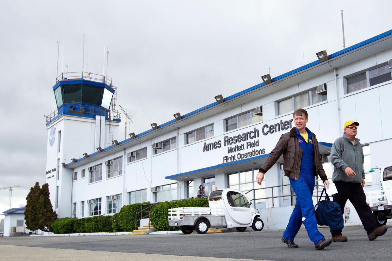
JSC2011-E-040202 (2 March 2011) --- NASA astronaut Chris Ferguson, STS-135 commander, departs from the Moffett Field (Calif.) flight operations center for his trip home to Houston after he and his crew trained in the Vertical Motion Simulator (VMS) at NASA's Ames Research Center in Mountain View, March 2, 2011. Photo credit: NASA Photo/Houston Chronicle, Smiley N. Pool
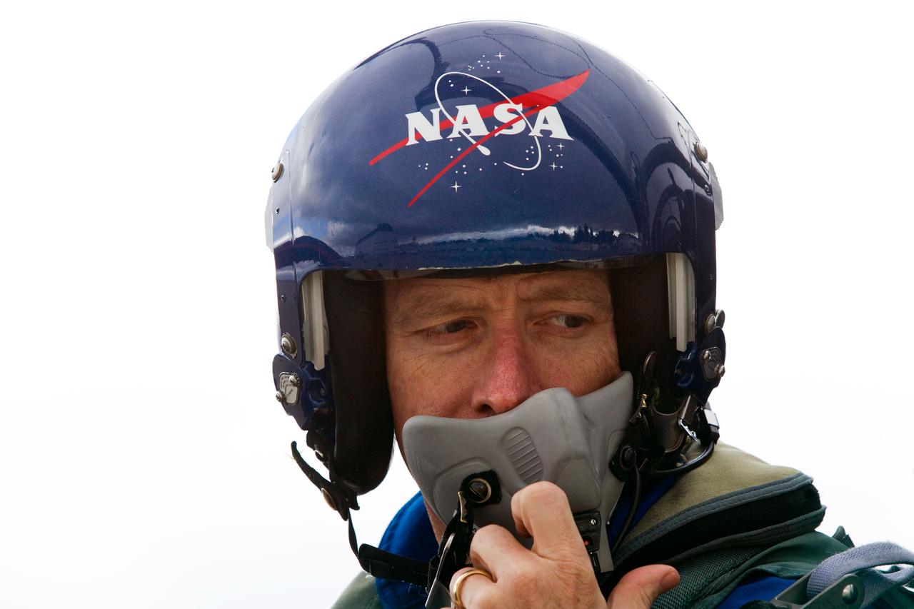
JSC2011-E-040243 (2 March 2011) --- NASA astronaut Chris Ferguson, STS-135 commander, prepares for departure from Moffett Field as he flies a T-38 trainer home to Houston after the crew of STS-135 trained in the Vertical Motion Simulator (VMS) at NASA's Ames Research Center on March 2, 2011, in Mountain View, Calif. Photo credit: NASA Photo/Houston Chronicle, Smiley N. Pool
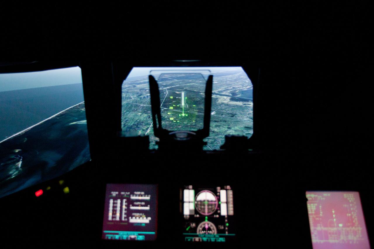
JSC2011-E-040200 (2 March 2011) --- The landing approach to the Kennedy Space Center is seen in a heads up display as the STS-135 crew trains in the Vertical Motion Simulator (VMS) at NASA's Ames Research Center in Mountain View, Calif., on March 2, 2011. Photo credit: NASA Photo/Houston Chronicle, Smiley N. Pool
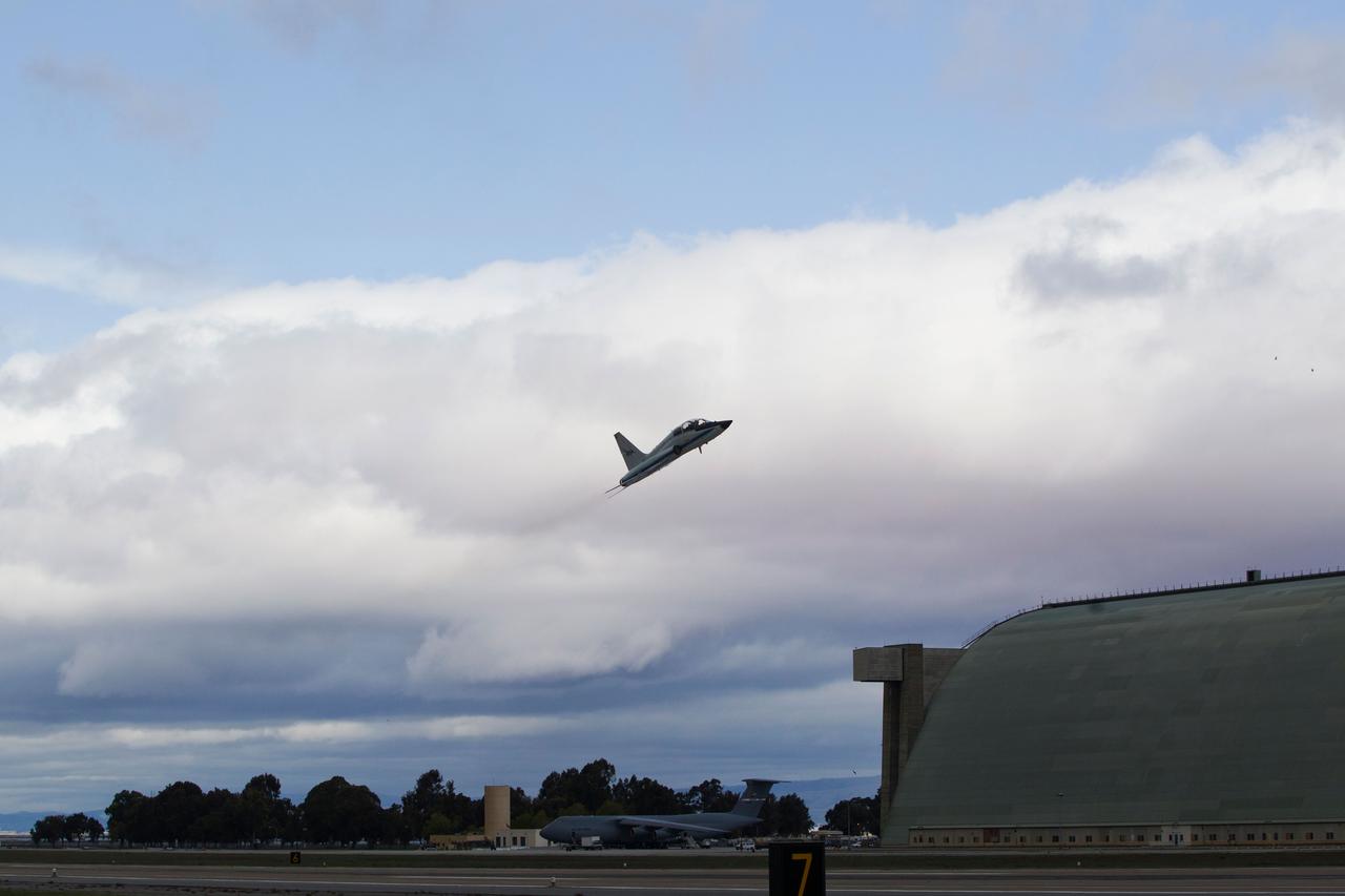
JSC2011-E-040205 (2 March 2011) --- A NASA T-38 jet trainer piloted by astronaut Chris Ferguson, STS-135 commander, takes off from Moffett Field in California for a flight home to Houston after Ferguson and his crew trained in the Vertical Motion Simulator (VMS) at NASA's Ames Research Center in Mountain View, March 2, 2011. Photo credit: NASA Photo/Houston Chronicle, Smiley N. Pool
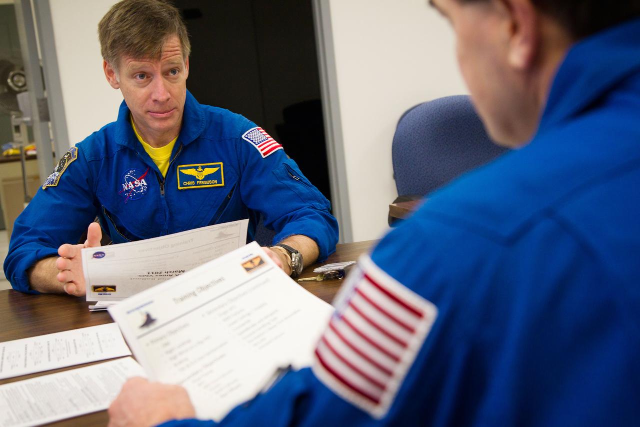
JSC2011-E-040193 (2 March 2011) --- NASA astronaut Chris Ferguson (left), STS-135 commander, confers with astronaut Rex Walheim, mission specialist, as the Atlantis crew participates in a briefing before a training session in the Vertical Motion Simulator (VMS) at NASA's Ames Research Center in Mountain View, Calif. March 2, 2011. Photo credit: NASA Photo/Houston Chronicle, Smiley N. Pool
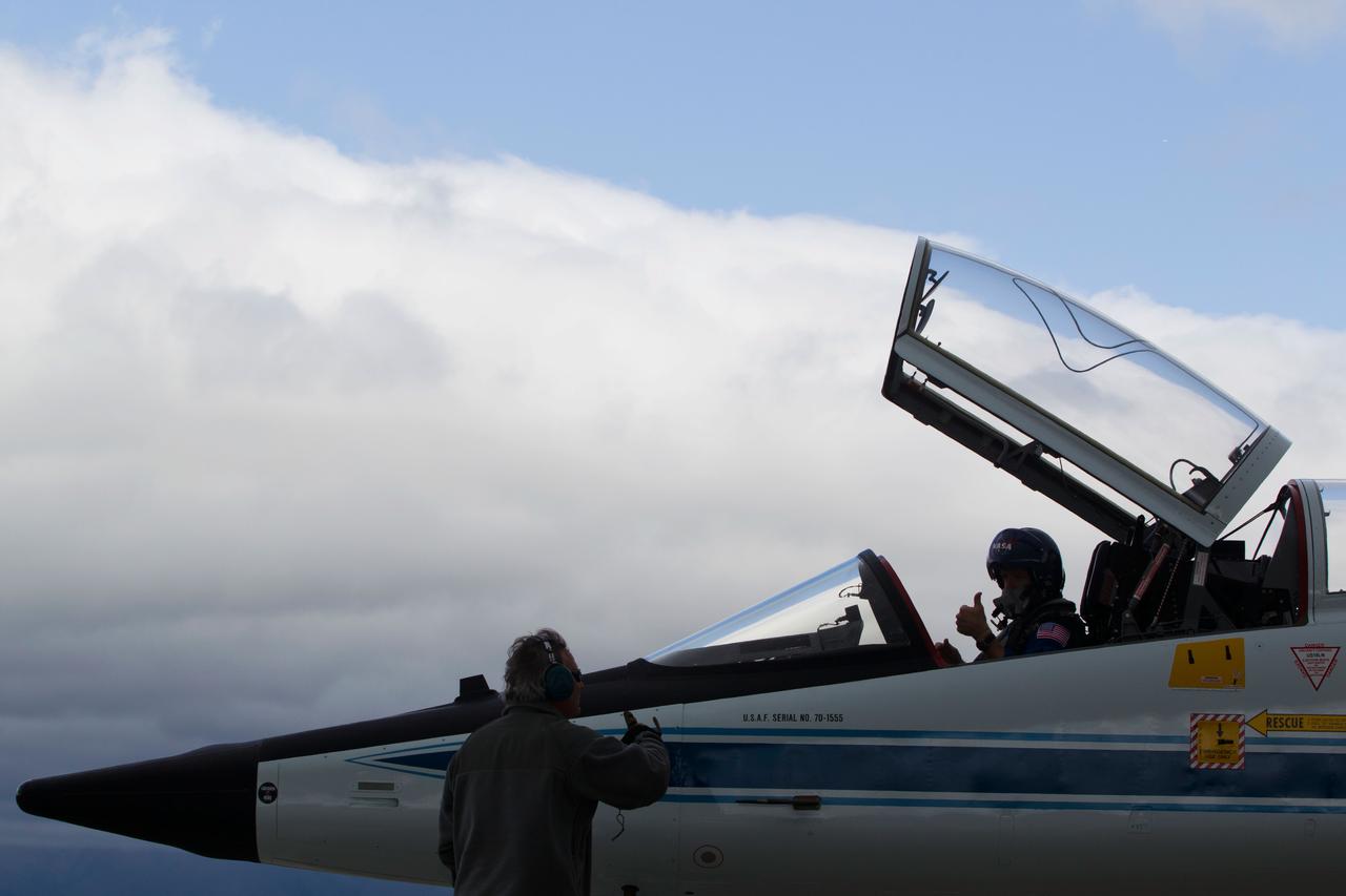
JSC2011-E-040204 (2 March 2011) --- NASA astronaut Chris Ferguson, STS-135 commander, prepares for departure from Moffett Field in a T-38 trainer home to Houston after the crew of STS-135 trained in the Vertical Motion Simulator (VMS) at NASA's Ames Research Center in Mountain View, Calif. on March 2, 2011, Photo credit: NASA Photo/Houston Chronicle, Smiley N. Pool
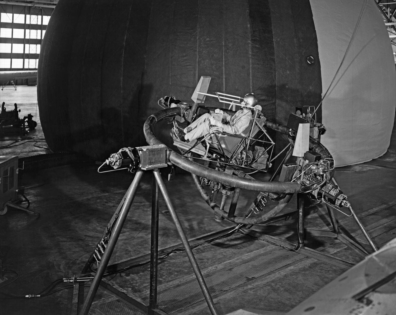
Lunar Take Off Simulator: This simulator is used by scientists at the Langley Research Center ... to help determine human ability to control a lunar launch vehicle in vertical alignment during takeoff from the moon for rendezvous with a lunar satellite vehicle on the return trip to earth. The three-axis chair, a concept which allows the pilot to sit upright during launch, gives the navigator angular motion (pitch, role, and yaw) cues as he operates the vehicle through a sidearm control system. The sight apparatus in front of the pilot's face enables him to align the vehicle on a course toward a chosen star, which will be followed as a guidance reference during the lunar launch. The pilot's right hand controls angular motions, while his left hand manipulates the thrust lever. The simulator is designed for operation inside an artificial planetarium, where a star field will be projected against the ceiling during "flights". The tests are part of an extensive NASA program at Langley in the study of problems relating to a manned lunar mission. (From a NASA Langley, photo release caption.)
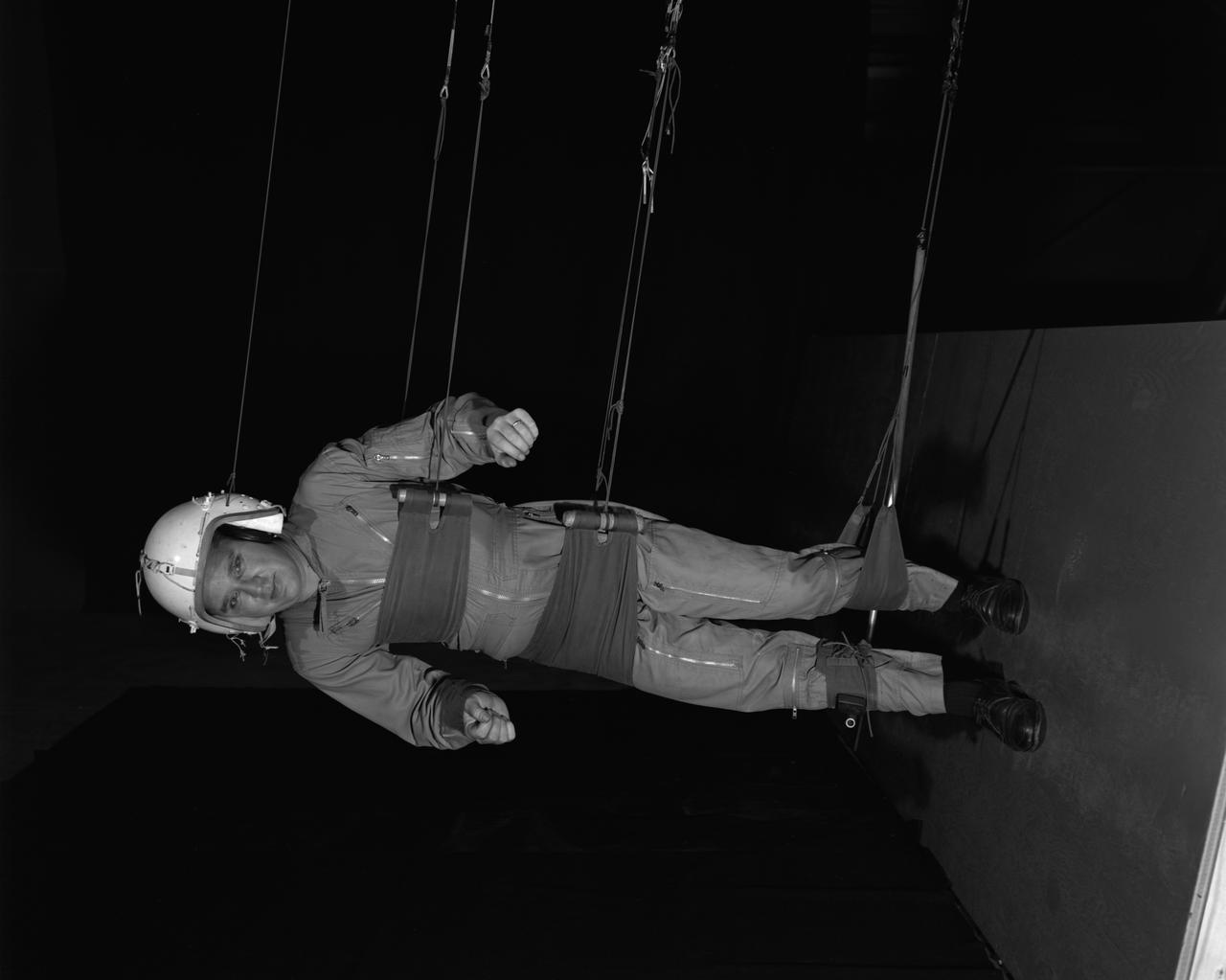
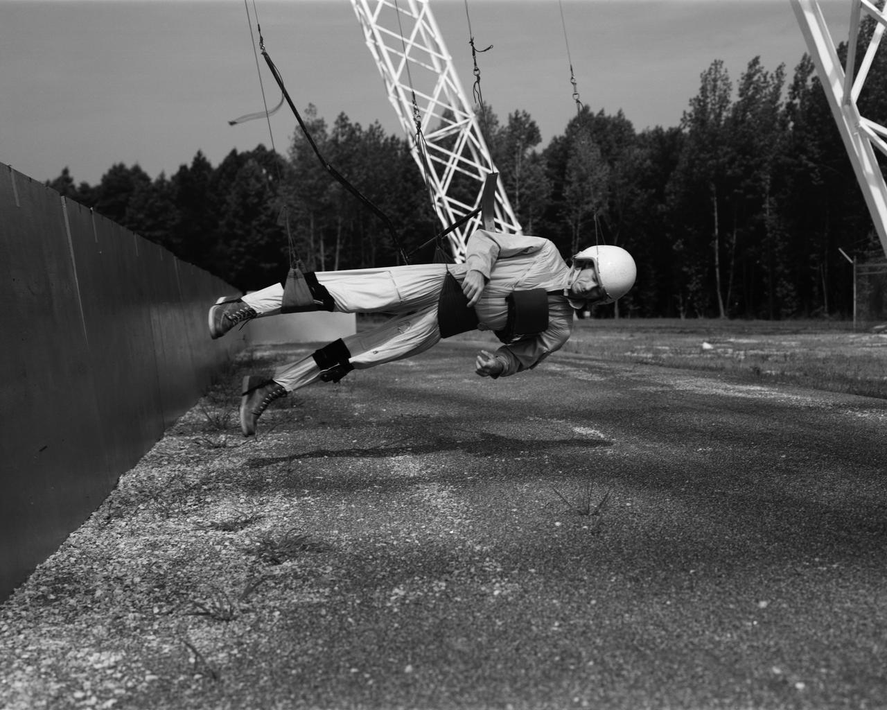
Reduced Gravity Walking Simulator located in the hangar at Langley Research Center. The initial version of this simulator was located inside the hangar. Later a larger version would be located at the Lunar Landing Facility. The purpose of this simulator was to study the subject while walking, jumping or running. Researchers conducted studies of various factors such as fatigue limit, energy expenditure, and speed of locomotion. A.W. Vigil wrote in his paper Discussion of Existing and Planned Simulators for Space Research, When the astronauts land on the moon they will be in an unfamiliar environment involving, particularly, a gravitational field only one-sixth as strong as on earth. A novel method of simulating lunar gravity has been developed and is supported by a puppet-type suspension system at the end of a long pendulum. A floor is provided at the proper angle so that one-sixth of the subject' s weight is supported by the floor with the remainder being supported by the suspension system. This simulator allows almost complete freedom in vertical translation and pitch and is considered to be a very realistic simulation of the lunar walking problem. For this problem this simulator suffers only slightly from the restrictions in lateral movement it puts on the test subject. This is not considered a strong disadvantage for ordinary walking problems since most of the motions do, in fact, occur in the vertical plane. However, this simulation technique would be severely restrictive if applied to the study of the extra-vehicular locomotion problem, for example, because in this situation complete six degrees of freedom are rather necessary. This technique, in effect, automatically introduces a two-axis attitude stabilization system into the problem. The technique could, however, be used in preliminary studies of extra-vehicular locomotion where, for example, it might be assumed that one axis of the attitude control system on the astronaut maneuvering unit may have failed. -- Published in James R. Hansen, Spaceflight Revolution: NASA Langley Research Center From Sputnik to Apollo, NASA SP-4308, p. 377 A.W. Vigil, Discussion of Existing and Planned Simulators for Space Research, Paper presented at Conference on the Role of Simulation in Space Technology, Blacksburg, VA, August 17-21, 1964.
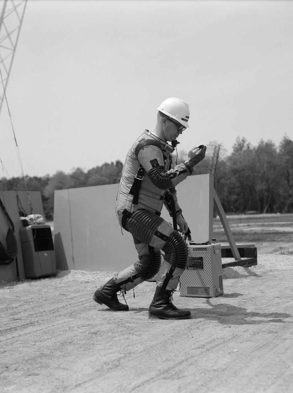
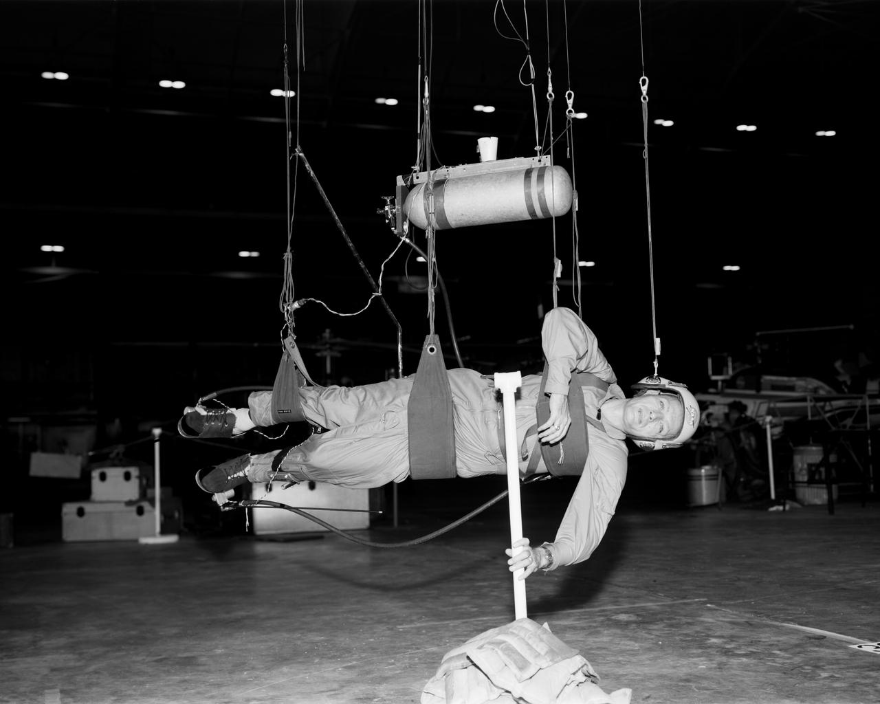
Special "space" suit for the Reduced Gravity Walking Simulator located at the Lunar Landing Facility. The purpose of this simulator was to study the subject while walking, jumping or running. Researchers conducted studies of various factors such as fatigue limit, energy expenditure, and speed of locomotion. A.W. Vigil described the purpose of the simulator in his paper "Discussion of Existing and Planned Simulators for Space Research," "When the astronauts land on the moon they will be in an unfamiliar environment involving, particularly, a gravitational field only one-sixth as strong as on earth. A novel method of simulating lunar gravity has been developed and is supported by a puppet-type suspension system at the end of a long pendulum. A floor is provided at the proper angle so that one-sixth of the subject's weight is supported by the floor with the remainder being supported by the suspension system. This simulator allows almost complete freedom in vertical translation and pitch and is considered to be a very realistic simulation of the lunar walking problem. For this problem this simulator suffers only slightly from the restrictions in lateral movement it puts on the test subject. This is not considered a strong disadvantage for ordinary walking problems since most of the motions do, in fact, occur in the vertical plane. However, this simulation technique would be severely restrictive if applied to the study of the extra-vehicular locomotion problem, for example, because in this situation complete six degrees of freedom are rather necessary. This technique, in effect, automatically introduces a two-axis attitude stabilization system into the problem. The technique could, however, be used in preliminary studies of extra-vehicular locomotion where, for example, it might be assumed that one axis of the attitude control system on the astronaut maneuvering unit may have failed." -- Published in James R. Hansen, Spaceflight Revolution: NASA Langley Research Center From Sputnik to Apollo, (Washington: NASA, 1995), p. 377; A.W. Vigil, "Discussion of Existing and Planned Simulators for Space Research," Paper presented at Conference on the Role of Simulation in Space Technology," Blacksburg, VA, August 17-21, 1964.
Test subject wearing the pressurized "space" suit for the Reduced Gravity Walking Simulator located at the Lunar Landing Facility. The purpose of this simulator was to study the subject while walking, jumping or running. Researchers conducted studies of various factors such as fatigue limit, energy expenditure, and speed of locomotion. A.W. Vigil described the purpose of the simulator in his paper "Discussion of Existing and Planned Simulators for Space Research," "When the astronauts land on the moon they will be in an unfamiliar environment involving, particularly, a gravitational field only one-sixth as strong as on earth. A novel method of simulating lunar gravity has been developed and is supported by a puppet-type suspension system at the end of a long pendulum. A floor is provided at the proper angle so that one-sixth of the subject's weight is supported by the floor with the remainder being supported by the suspension system. This simulator allows almost complete freedom in vertical translation and pitch and is considered to be a very realistic simulation of the lunar walking problem. For this problem this simulator suffers only slightly from the restrictions in lateral movement it puts on the test subject. This is not considered a strong disadvantage for ordinary walking problems since most of the motions do, in fact, occur in the vertical plane. However, this simulation technique would be severely restrictive if applied to the study of the extra-vehicular locomotion problem, for example, because in this situation complete six degrees of freedom are rather necessary. This technique, in effect, automatically introduces a two-axis attitude stabilization system into the problem. The technique could, however, be used in preliminary studies of extra-vehicular locomotion where, for example, it might be assumed that one axis of the attitude control system on the astronaut maneuvering unit may have failed." -- Published in James R. Hansen, Spaceflight Revolution: NASA Langley Research Center From Sputnik to Apollo, (Washington: NASA, 1995), p. 377; A.W. Vigil, "Discussion of Existing and Planned Simulators for Space Research," Paper presented at Conference on the Role of Simulation in Space Technology," Blacksburg, VA, August 17-21, 1964.
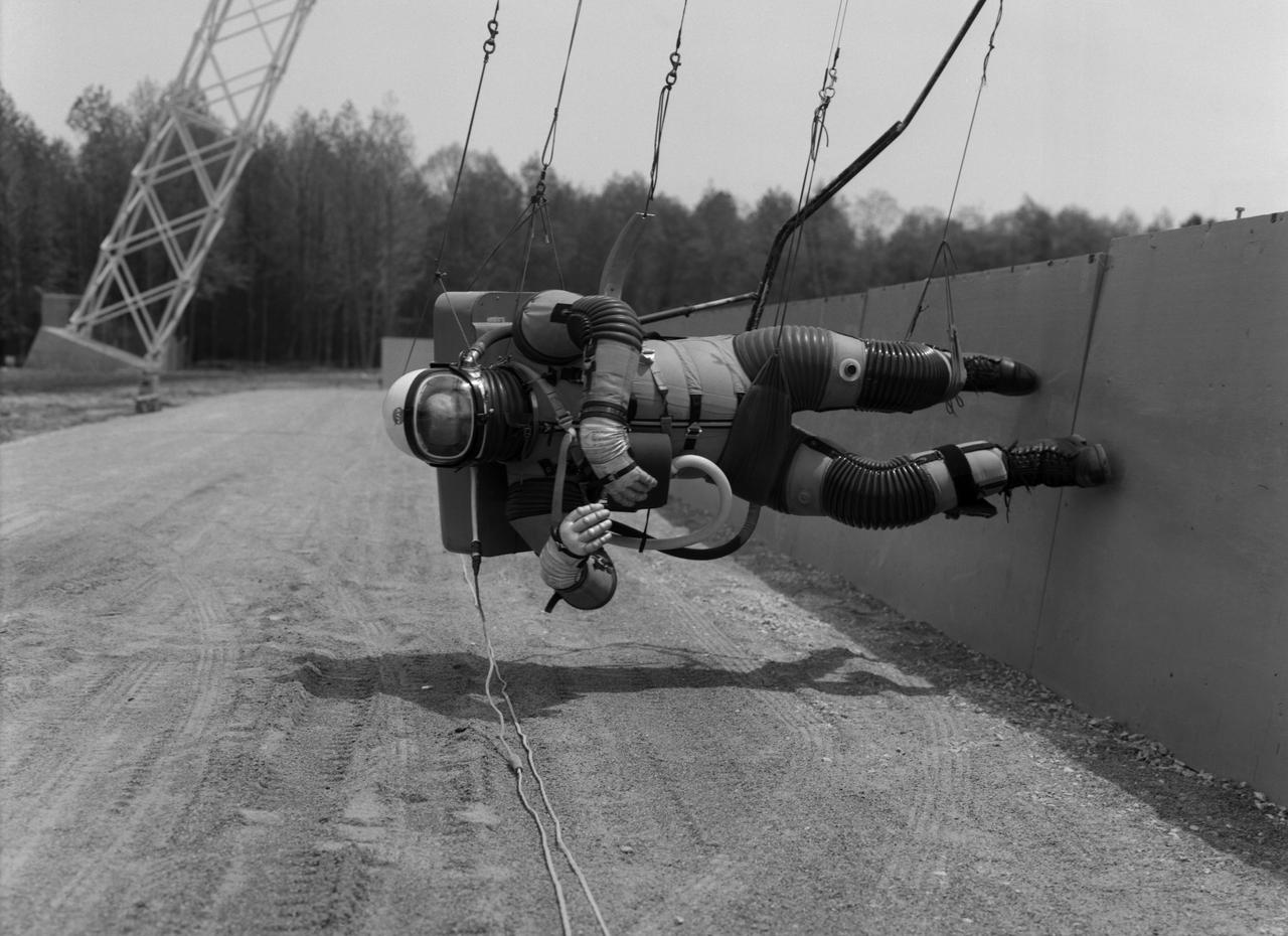
Astronaut Walt Cunningham on the Reduced Gravity Walking Simulator located at the Lunar Landing Facility. The purpose of this simulator was to study the subject while walking, jumping or running. Researchers conducted studies of various factors such as fatigue limit, energy expenditure, and speed of locomotion. A.W. Vigil described the purpose of the simulator in his paper "Discussion of Existing and Planned Simulators for Space Research," "When the astronauts land on the moon they will be in an unfamiliar environment involving, particularly, a gravitational field only one-sixth as strong as on earth. A novel method of simulating lunar gravity has been developed and is supported by a puppet-type suspension system at the end of a long pendulum. A floor is provided at the proper angle so that one-sixth of the subject's weight is supported by the floor with the remainder being supported by the suspension system. This simulator allows almost complete freedom in vertical translation and pitch and is considered to be a very realistic simulation of the lunar walking problem. For this problem this simulator suffers only slightly from the restrictions in lateral movement it puts on the test subject. This is not considered a strong disadvantage for ordinary walking problems since most of the motions do, in fact, occur in the vertical plane. However, this simulation technique would be severely restrictive if applied to the study of the extra-vehicular locomotion problem, for example, because in this situation complete six degrees of freedom are rather necessary. This technique, in effect, automatically introduces a two-axis attitude stabilization system into the problem. The technique could, however, be used in preliminary studies of extra-vehicular locomotion where, for example, it might be assumed that one axis of the attitude control system on the astronaut maneuvering unit may have failed." -- Published in James R. Hansen, Spaceflight Revolution: NASA Langley Research Center From Sputnik to Apollo, (Washington: NASA, 1995), p. 377; A.W. Vigil, "Discussion of Existing and Planned Simulators for Space Research," Paper presented at Conference on the Role of Simulation in Space Technology," Blacksburg, VA, August 17-21, 1964.

Astronaut Roger Chaffee on the Reduced Gravity Walking Simulator located at the Lunar Landing Facility. The purpose of this simulator was to study the subject while walking, jumping or running. Researchers conducted studies of various factors such as fatigue limit, energy expenditure, and speed of locomotion. A.W. Vigil, described the simulator as follows: "When the astronauts land on the moon they will be in an unfamiliar environment involving, particularly, a gravitational field only one-sixth as strong as on earth. A novel method of simulating lunar gravity has been developed and is supported by a puppet-type suspension system at the end of a long pendulum. A floor is provided at the proper angle so that one-sixth of the subject's weight is supported by the floor with the remainder being supported by the suspension system. This simulator allows almost complete freedom in vertical translation and pitch and is considered to be a very realistic simulation of the lunar walking problem. For this problem this simulator suffers only slightly from the restrictions in lateral movement it puts on the test subject. This is not considered a strong disadvantage for ordinary walking problems since most of the motions do, in fact, occur in the vertical plane. However, this simulation technique would be severely restrictive if applied to the study of the extra-vehicular locomotion problem, for example, because in this situation complete six degrees of freedom are rather necessary. This technique, in effect, automatically introduces a two-axis attitude stabilization system into the problem. The technique could, however, be used in preliminary studies of extra-vehicular locomotion where, for example, it might be assumed that one axis of the attitude control system on the astronaut maneuvering unit may have failed." -- Published in James R. Hansen, Spaceflight Revolution: NASA Langley Research Center From Sputnik to Apollo, NASA SP-4308, p. 377; A.W. Vigil, "Discussion of Existing and Planned Simulators for Space Research," Paper presented at Conference on the Role of Simulation in Space Technology," Blacksburg, VA, August 17-21, 1964.
Cable system which supports the test subject on the Reduced Gravity Walking Simulator. The purpose of this simulator was to study the subject while walking, jumping or running. Researchers conducted studies of various factors such as fatigue limit, energy expenditure, and speed of locomotion. A.W. Vigil described the purpose of the simulator as follows: "When the astronauts land on the moon they will be in an unfamiliar environment involving, particularly, a gravitational field only one-sixth as strong as on earth. A novel method of simulating lunar gravity has been developed and is supported by a puppet-type suspension system at the end of a long pendulum. A floor is provided at the proper angle so that one-sixth of the subject's weight is supported by the floor with the remainder being supported by the suspension system. This simulator allows almost complete freedom in vertical translation and pitch and is considered to be a very realistic simulation of the lunar walking problem. For this problem this simulator suffers only slightly from the restrictions in lateral movement it puts on the test subject. This is not considered a strong disadvantage for ordinary walking problems since most of the motions do, in fact, occur in the vertical plane. However, this simulation technique would be severely restrictive if applied to the study of the extra-vehicular locomotion problem, for example, because in this situation complete six degrees of freedom are rather necessary. This technique, in effect, automatically introduces a two-axis attitude stabilization system into the problem. The technique could, however, be used in preliminary studies of extra-vehicular locomotion where, for example, it might be assumed that one axis of the attitude control system on the astronaut maneuvering unit may have failed." -- Published in James R. Hansen, Spaceflight Revolution: NASA Langley Research Center From Sputnik to Apollo, (Washington: NASA, 1995); A.W. Vigil, "Discussion of Existing and Planned Simulators for Space Research," Paper presented at Conference on the Role of Simulation in Space Technology," Blacksburg, VA, August 17-21, 1964.