
Viking 2 30th!

Plains West of Viking Lander 2
Frost at the Viking Lander 2 Site

Viking 2 Image of Mars Utopian Plain
First Color Image of the Viking Lander 2 Site
Viking Lander 2 First Picture On The Surface Of Mars http://photojournal.jpl.nasa.gov/catalog/PIA00396

Viking Lander 2 Gerald A. Soffen Memorial Station Imaged from Orbit
Afternoon on Chryse Planitia - Viking Lander 1 Camera 2 Mosaic
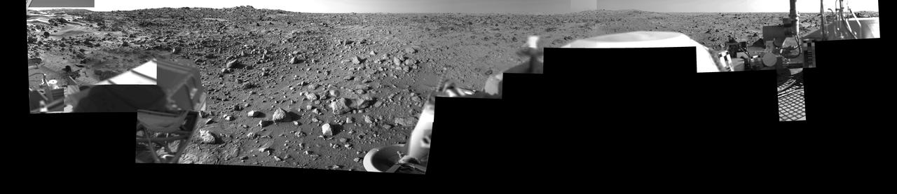
Morning on Chryse Planitia - Viking Lander 1 Camera 2 Mosaic

A paper collage interpreting the craters and ridged planes of Mars and the Viking 2 as it passed over Mar's surface on 2 November 1982, prior to landing.
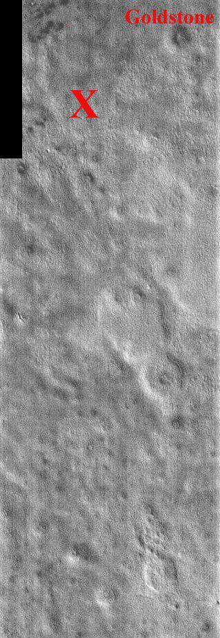
This portion of NASA Mars Odyssey image covers NASA Viking 2 landing site shown with the X. The second landing on Mars took place September 3, 1976 in Utopia Planitia. The exact location of Lander 2 is not as well established as Lander 1 because there were no clearly identifiable features in the lander images as there were for the site of Lander 1. The Utopia landing site region contains pedestal craters, shallow swales and gentle ridges. The crater Goldstone was named in honor of the Tracking Station in the desert of California. The two Viking Landers operated for over 6 years (nearly four martian years) after landing. This one band IR (band 9 at 12.6 microns) image shows bright and dark textures, which are primarily due to differences in the abundance of rocks on the surface. The relatively cool (dark) regions during the day are rocky or indurated materials, fine sand and dust are warmer (bright). Many of the temperature variations are due to slope effects, with sun-facing slopes warmer than shaded slopes. The dark rings around several of the craters are due to the presence of rocky (cool) material ejected from the crater. These rocks are well below the resolution of any existing Mars camera, but THEMIS can detect the temperature variations they produce. Daytime temperature variations are produced by a combination of topographic (solar heating) and thermophysical (thermal inertia and albedo) effects. Due to topographic heating the surface morphologies seen in THEMIS daytime IR images are similar to those seen in previous imagery and MOLA topography. http://photojournal.jpl.nasa.gov/catalog/PIA04023
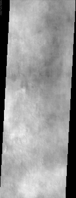
Splotchy water ice clouds obscure the northern lowland plains in the region where NASA Viking 2 spacecraft landed in this image by NASA Mars Odyssey spacecraft.
Mars digital-image mosaic merged with color of the MC-2 quadrangle, Diacria region of Mars. This image is from NASA's Viking Orbiter 1. http://photojournal.jpl.nasa.gov/catalog/PIA00162
This image from NASA Mars Odyssey spacecraft shows Rampart crater in Utopia Planitia, west of NASA Viking 2 landing site. http://photojournal.jpl.nasa.gov/catalog/PIA04029

Water ice mixed with dust form the residual north polar ice cap brown color in these images from NASA's Viking Orbiter 2. http://photojournal.jpl.nasa.gov/catalog/PIA00152
Operation of the surface sampler in obtaining Martian soil for NASA's Viking 2 molecular analysis experiment. Dubbed Bonneville Salt Flats, the exposure of thin crust appeared unique in contrast with surrounding materials. http://photojournal.jpl.nasa.gov/catalog/PIA00145
A conspicuous fretted channel, Reull Valles, Mars which dissects wall deposits of the large Hellas impact basin, trends southeast towards the basin floor as seen by NASA's Viking Orbiter 2. http://photojournal.jpl.nasa.gov/catalog/PIA00154
This picture from NASA's Viking Orbiter 2 shows areas of central Valles Marineris, Mars, including Candor Chasm lower left, Ophir Chasm lower right, and Hebes Chasm upper right. http://photojournal.jpl.nasa.gov/catalog/PIA00155
Mars Syria Planum-centered volcanism and tectonism produced fractures, narrow to broad grabens, large scarps, and broad fold and thrust ridges that deformed a basement complex captured by NASA's Viking Orbiter 2. http://photojournal.jpl.nasa.gov/catalog/PIA00154
This picture centered at latitude 10 degrees S., longitude 74 degrees W. shows much of Mars Melas Chasm and a portion of Candor Chasm upper right in central Valles Marineris as seen by NASA's Viking Orbiter 2. http://photojournal.jpl.nasa.gov/catalog/PIA00156
Tharsis-centered volcanic and tectonic activity resulted in the formation of radial grabens of Memnonia Fossae, which cut materials of the ancient cratered highlands and the relatively young, highland-embaying lava flows as seen by NASA's Viking Orbiter 2. http://photojournal.jpl.nasa.gov/catalog/PIA00151
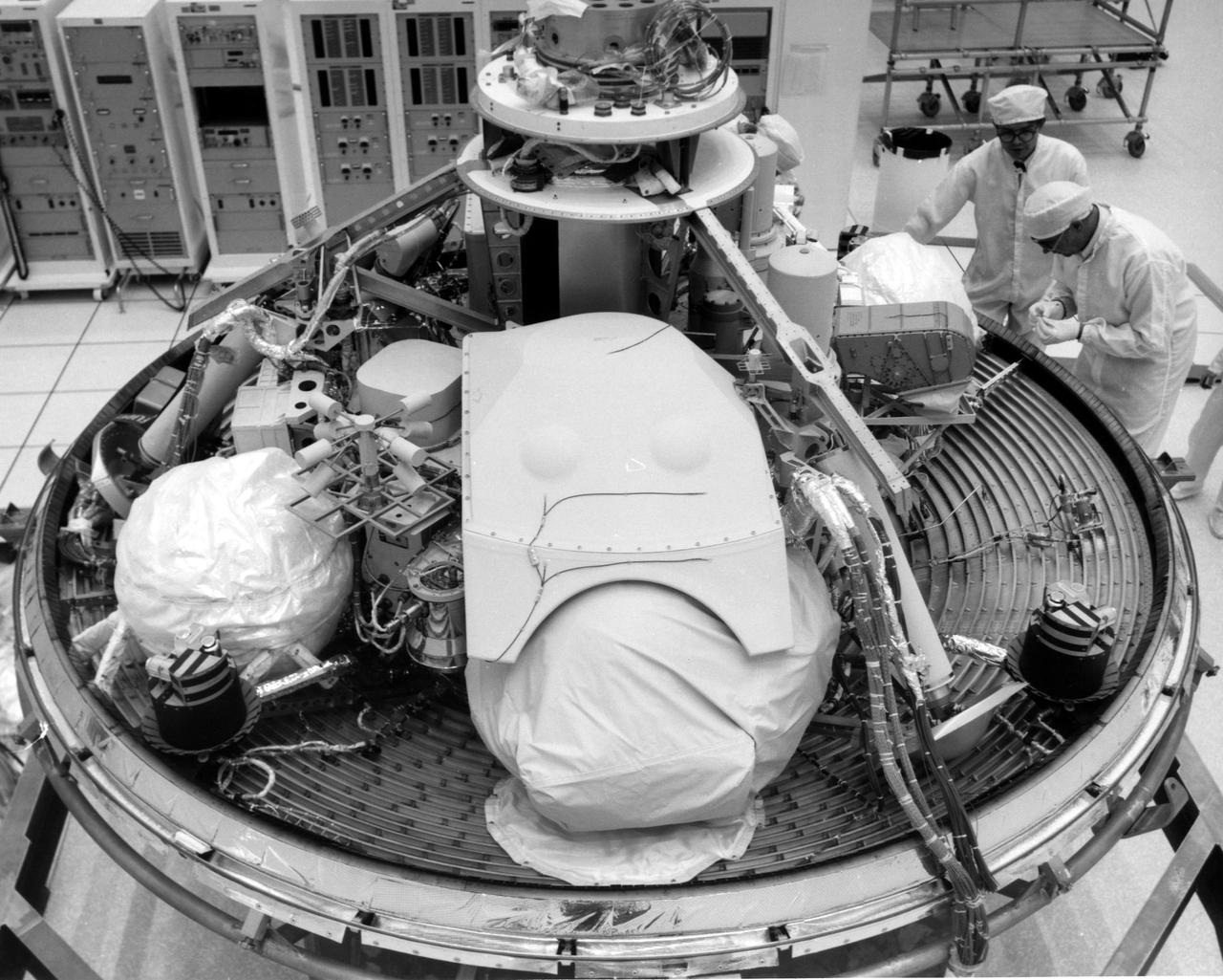
CAPE CANAVERAL, Fla. -- At the Kennedy Space Center in Florida, technicians inspect the Viking Lander 2 in Kennedy's Spacecraft Assembly and Encapsulation Facility 1. The first Viking is scheduled for launch from Launch Complex 41 no earlier than Aug. 11, 1975, the second, no earlier than Aug. 21, 1975. Once in orbit around Mars, the lander will detach and descend to the planet's surface to conduct further investigation. The Viking's 440-million-mile journey to the Red Planet will take about 11 months. Photo Credit: NASA
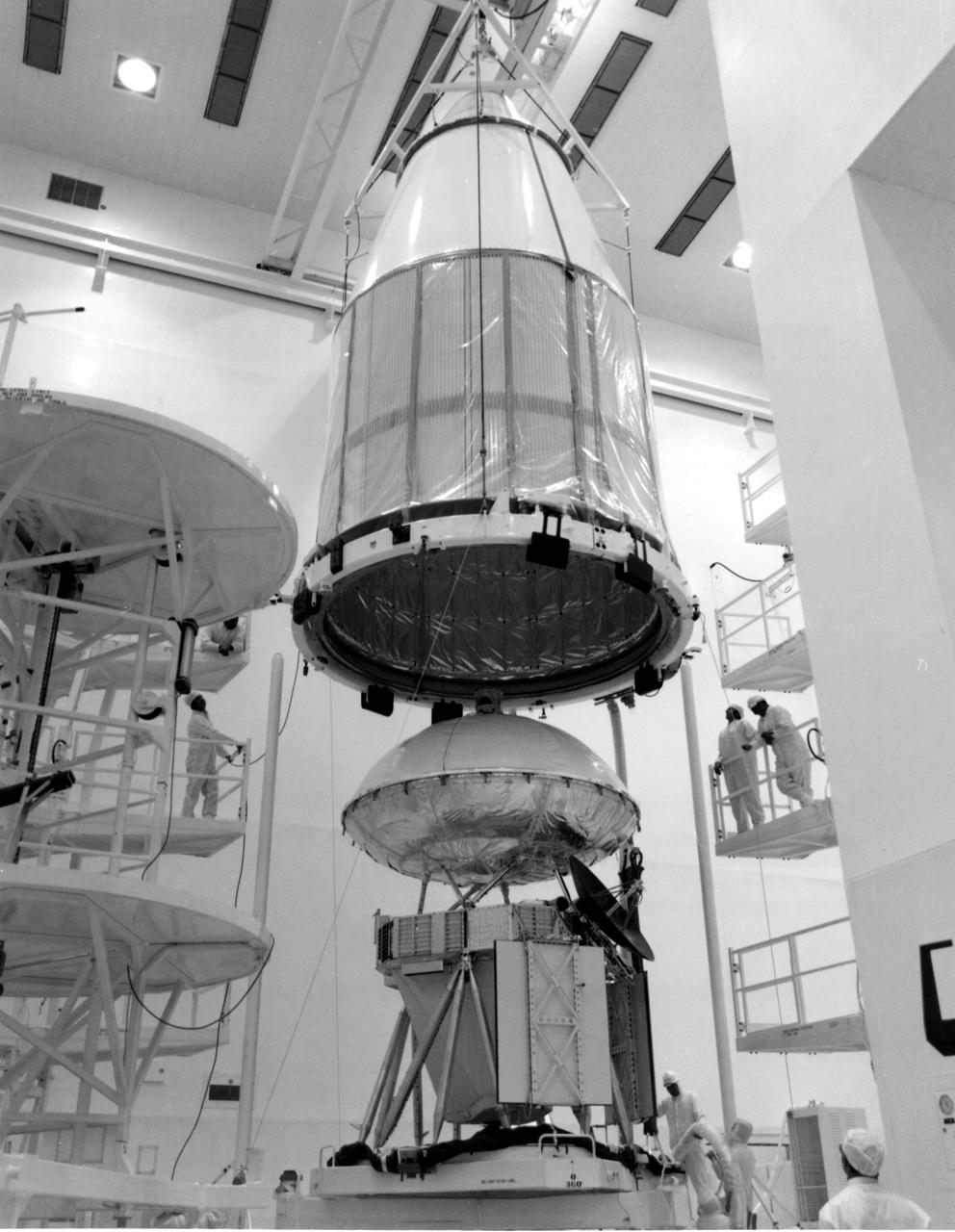
KENNEDY SPACE CENTER, FLA. -- The mated orbiter and lander for Viking A were encapsulated within a Centaur shroud at Spacecraft Assembly and Encapsulation Facility 2 (SAEF-2) today. The spacecraft, one of two to be launched toward Mars atop Titan_Centaurs in August, is to be moved to Launch Complex 41 on March 31 for extensive testing. KSC's Unmanned Launch Operations Directorate is scheduled to launch the twin Vikings during a 10-day period in August.
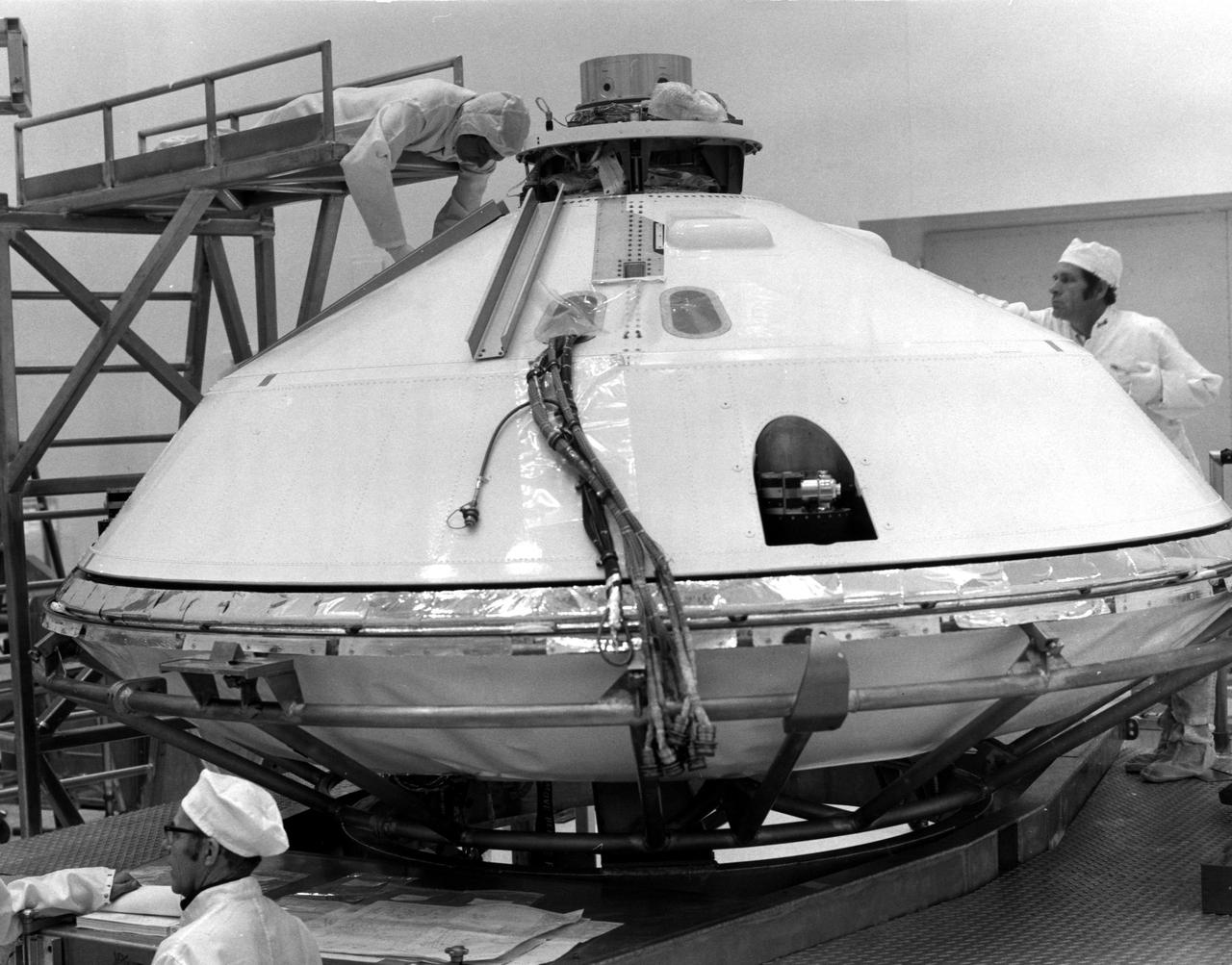
KENNEDY SPACE CENTER, FLA. -- Technicians prepared for removal of Viking Lander 1's aeroshell cover in KSC's Spacecraft Assembly and Encapsulation Facility 2 (SAEF-2) today. The cover remains over the Lander throughout its 440,000,000-mile journey to Mars. After the Lander separates from the Orbiter, the aeroshell will help to decelerate the speed of descent and will serve as a heat shield. After the aeroshell separates, the Lander's parachute will deploy at about 4,000 feet altitude to further slow descent for a soft landing on the Red Planet. The Kennedy Space Center will launch the first Viking from Complex 41, Cape Canaveral, no earlier than Aug. 11. The second Viking will be launched no earlier than Aug. 21.
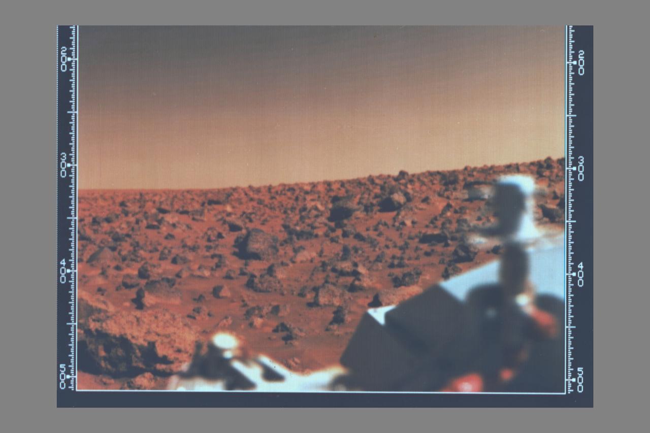
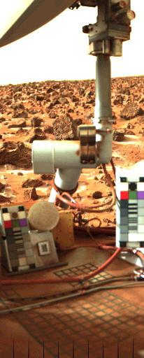
Viking 2 A utopian bright summer afternoon on Mars -- Looking south from Viking 2 on September 7, 1976 the orange-red surface of the nearly level plain upon which the spacecraft sits is seen strewn with rocks as large as three feet across. Many of these rocks are porous and sponge-like, similar to some of Earth's volcanic rocks. Other rocks are coarse-grained such as the large rock at lower left. Between the rocks, the surface is blanketed with fine-grained materials that, in places, is piled into small drifts and banked against some of the larger blocks. The cylindrical mast with the orange cable is the low-gain antenna used to receive cammands form Earth. (JPL ref: P-17690 color)

The Centaur Standard Shroud prepared for a jettison test in the Space Power Facility at the National Aeronautics and Space Administration’s (NASA) Plum Brook Station. In the late 1960s NASA engineers were planning the ambitious new Viking mission to send two rover vehicles to the surface of Mars. The Viking rovers were the heaviest payloads ever attempted by the Centaur second-stage rocket. Each Viking was over three times the weight of the Atlas-Centaur’s previous heaviest payload. Consequently, NASA engineers sought to mate the Centaur with the more powerful Titan III booster for the launches. General Dynamics created a new version of the Centaur, D-1T, specifically for Titan. The D-1T’s most significant modification was a completely new shroud designed by Lockheed, called the Centaur Standard Shroud. The conical two-piece covering encapsulated the payload to protect it against adverse conditions and improve the aerodynamics as the launch vehicle passed through the atmosphere. The shroud would be jettisoned when the vehicle reached the edge of space. A string of tests were conducted in Plum Brook’s Nuclear Rocket Dynamics and Control Facility (B-3) during 1973 and 1974. The new shroud performed flawlessly during the actual Viking launches in 1975. Viking 1 and 2 operated on the Martian surface until November 1982 and April 1980, respectively.
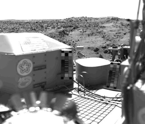
The flag of the United States stands on the surface of Mars. It is mounted on the housing of NASA's Viking 1's nuclear power system. Also seen are the U.S. Bicentennial symbol and a student designed Viking emblem. The bright flat surface near the center is the seismometer container. This picture was taken on July 23 at about 2:30 p.m. Mars time. The view is west of the spacecraft and includes a series of low hills. The blocky hill in the center appears to be part of a crater rim. The dark, rocky stripes may be material ejected from the crater. The light areas are dune-like and may be accumulations of windblown sand or dust. http://photojournal.jpl.nasa.gov/catalog/PIA00388
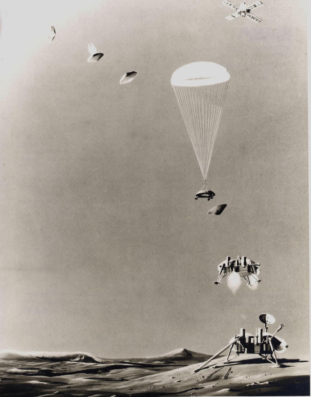
This is an artist's conception of the sequence of events that will take place just prior to landing a life-detection laboratory on the surface of Mars on July 4, 1976. Above right, the Viking spacecraft, composed of an orbiter and a lander, has been in orbit around the Red Planet since June 19, 1976, taking pictures of the planned landing site to ascertain its safety before releasing the lander (top, left) for its threeto five-hour descent. Protected by aeroshells, the heat-sterilized lander hurtles into the thin Martian atmosphere at a speed of about 10,000 mph, to be slowed first by aerodynamic drag until the shell is discarded, then by parachute (center) and finally by retrorockets to assure a gentle landing. Instruments will study the structure and composition of the Martian atmosphere as the lander drifts down. Viking 2 is scheduled to arrive at Mars on Aug. 7 and touch down on the surface on Sept. 4.
![This is the first photograph ever taken on the surface of the planet Mars. It was obtained by Viking 1 just minutes after the spacecraft landed successfully early today [July 20, 1976]. The center of the image is about 1.4 meters (five feet) from Viking Lander camera #2. We see both rocks and finely granulated material--sand or dust. Many of the small foreground rocks are flat with angular facets. Several larger rocks exhibit irregular surfaces with pits and the large rock at top left shows intersecting linear cracks. Extending from that rock toward the camera is a vertical linear dark band which may be due to a one-minute partial obscuration of the landscape due to clouds or dust intervening between the sun and the surface. Associated with several of the rocks are apparent signs of wind transport of granular material. The large rock in the center is about 10 centimeters (4 inches) across and shows three rough facets. To its lower right is a rock near a smooth portion of the Martian surface probably composed of very fine-grained material. It is possible that the rock was moved during Viking 1 descent maneuvers, revealing the finer-grained basement substratum; or that the fine-grained material has accumulated adjacent to the rock. There are a number of other furrows and depressions and places with fine-grained material elsewhere in the picture. At right is a portion of footpad #2. Small quantities of fine grained sand and dust are seen at the center of the footpad near the strut and were deposited at landing. The shadow to the left of the footpad clearly exhibits detail, due to scattering of light either from the Martian atmosphere or from the spacecraft, observable because the Martian sky scatters light into shadowed areas. http://photojournal.jpl.nasa.gov/catalog/PIA00381](https://images-assets.nasa.gov/image/PIA00381/PIA00381~thumb.jpg)
This is the first photograph ever taken on the surface of the planet Mars. It was obtained by Viking 1 just minutes after the spacecraft landed successfully early today [July 20, 1976]. The center of the image is about 1.4 meters (five feet) from Viking Lander camera #2. We see both rocks and finely granulated material--sand or dust. Many of the small foreground rocks are flat with angular facets. Several larger rocks exhibit irregular surfaces with pits and the large rock at top left shows intersecting linear cracks. Extending from that rock toward the camera is a vertical linear dark band which may be due to a one-minute partial obscuration of the landscape due to clouds or dust intervening between the sun and the surface. Associated with several of the rocks are apparent signs of wind transport of granular material. The large rock in the center is about 10 centimeters (4 inches) across and shows three rough facets. To its lower right is a rock near a smooth portion of the Martian surface probably composed of very fine-grained material. It is possible that the rock was moved during Viking 1 descent maneuvers, revealing the finer-grained basement substratum; or that the fine-grained material has accumulated adjacent to the rock. There are a number of other furrows and depressions and places with fine-grained material elsewhere in the picture. At right is a portion of footpad #2. Small quantities of fine grained sand and dust are seen at the center of the footpad near the strut and were deposited at landing. The shadow to the left of the footpad clearly exhibits detail, due to scattering of light either from the Martian atmosphere or from the spacecraft, observable because the Martian sky scatters light into shadowed areas. http://photojournal.jpl.nasa.gov/catalog/PIA00381
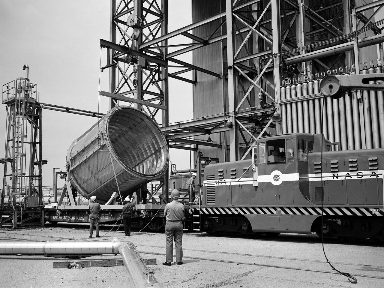
A section of the Centaur Standard Shroud transported to Nuclear Rocket Dynamics and Control Facility, or B-3 Test Stand, at the National Aeronautics and Space Administration’s (NASA) Plum Brook Station. B-3 was built in the early 1960s to test full-scale liquid hydrogen fuel systems in simulated altitude conditions. The facility was used in 1972, however, for testing of the Centaur Standard Shroud’s ejection system. In the late 1960s NASA engineers were planning the ambitious new Viking mission to send two rover vehicles to the surface of Mars. The Viking rovers were the heaviest payloads ever attempted and were over three times the weight of Atlas-Centaur’s previous heaviest payload. Consequently, NASA engineers selected the more powerful the Titan III rocket booster to mate with the Centaur. Concurrently, General Dynamics was in the process of introducing a new Centaur model for Titan—the D-1T. The biggest change for the D-1T was a completely new shroud designed by Lockheed, called the Centaur Standard Shroud. The shroud, its insulation, the Centaur ground-hold purge system, and the hydrogen tank venting system were all studied in B-3. After more than two years of preparations, the tests were run between April and July 1973. The tests determined the ultimate flight loads on two axes, established the Centaur’s load sharing, the level of propellant boiloff during launch holds, and the vent system capacity. The Centaur Standard Shroud performed flawlessly during the August 20 and September 9, 1975 launches of Viking 1 and 2.
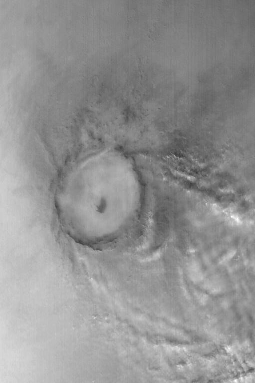
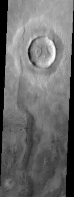
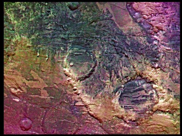
Mie Crater, a large basin formed by asteroid or comet impact in Utopia Planitia, lies at the center of this Mars Global Surveyor (MGS) Mars Orbiter Camera (MOC) red wide angle image. The crater is approximately 104 km (65 mi) across. To the east and southeast (toward the lower right) of Mie, in this 5 December 2003 view, are clouds of dust and water ice kicked up by local dust storm activity. It is mid-winter in the northern hemisphere of Mars, a time when passing storms are common on the northern plains of the red planet. Sunlight illuminates this image from the lower left; Mie Crater is located at 48.5°N, 220.3°W. Viking 2 landed west/southwest of Mie Crater, off the left edge of this image, in September 1976. http://photojournal.jpl.nasa.gov/catalog/PIA04930
The National Aeronautics and Space Administration (NASA) Lewis Research Center’s Launch Vehicle Directorate in front of a full-scale model of the Centaur second-stage rocket. The photograph was taken to mark Centaur’s fiftieth launch. NASA Lewis managed the Centaur Program since 1962. At that time, the only prior launch attempt ended in failure. Lewis improved the spacecraft and tested it extensively throughout the early 1960s. In May 1966 an Atlas-Centaur sent the Surveyor spacecraft to the moon. It was the first successful soft landing on another planet. The Launch Vehicles Division was formed in 1969 to handle the increasing number of Centaur launches. The Lewis team became experts at integrating the payload with the Centaur and calculating proper trajectories for the missions. Centaur’s first 50 missions included Orbiting Astronomical Observatories, the Mariner 6 and 7 flybys of Mars, Mariner 9 which was the first spacecraft to orbit around another planet, the Pioneer 10 and 11 missions to the outer solar system, the Mariner 10 flyby of Venus and Mercury, the Viking 1 and 2 Mars landers, Voyagers 1 and 2 missions to Jupiter, Saturn, Uranus, and Neptune, and the Pioneer 12 and 13 flights to Venus.
This image is illuminated by sunlight from the upper left. Martian Dairy Products? If parts of the south polar cap can look like swiss cheese (see "Martian "Swiss Cheese""), then parts of the north polar cap might as well look like some kind of cheese, too. This picture shows a cottage cheese-like texture on the surface of a part of the residual--summertime--north polar cap. The north polar cap surface is mostly covered by pits, cracks, small bumps and knobs. In this image, the cap surface appears bright and the floors of pits look dark. Based upon observations made by the Mariner 9 and Viking orbiters in the 1970s, the north polar residual cap is thought to contain mostly water ice because its summertime temperature is usually near the freezing point of water and water vapor was observed by the Vikings to be coming off the cap during summer. The south residual cap is different--its temperatures in summer remain cold enough to freeze carbon dioxide, and very little to no water vapor has been observed to come off the south cap in summer. The pits that have developed on the north polar cap surface are closely-spaced relative to the very different depressions in the south polar cap. The pits are estimated from the length of shadows cast in them to be less than about 2 meters (5.5 feet) deep. These pits probably develop slowly over thousands of years of successive spring and summer seasons. This picture was taken by the Mars Global Surveyor (MGS) Mars Orbiter Camera (MOC) during northern summer on April 5, 1999. The picture is located near 82.1°N, 329.6°W and covers an area 1.5 km wide by 3 km long (0.9 x 1.8 miles) at a resolution of 3 meters (10 ft) per pixel. http://photojournal.jpl.nasa.gov/catalog/PIA02369
![This image from NASA's Mars Reconnaissance Orbiter (MRO) shows Mars' surface in detail. Mars has captured the imagination of astronomers for thousands of years, but it wasn't until the last half a century that we were able to capture images of its surface in detail. This particular site on Mars was first imaged in 1965 by the Mariner 4 spacecraft during the first successful fly-by mission to Mars. From an altitude of around 10,000 kilometers, this image (the ninth frame taken) achieved a resolution of approximately 1.25 kilometers per pixel. Since then, this location has been observed by six other visible cameras producing images with varying resolutions and sizes. This includes HiRISE (highlighted in yellow), which is the highest-resolution and has the smallest "footprint." This compilation, spanning Mariner 4 to HiRISE, shows each image at full-resolution. Beginning with Viking 1 and ending with our HiRISE image, this animation documents the historic imaging of a particular site on another world. In 1976, the Viking 1 orbiter began imaging Mars in unprecedented detail, and by 1980 had successfully mosaicked the planet at approximately 230 meters per pixel. In 1999, the Mars Orbiter Camera onboard the Mars Global Surveyor (1996) also imaged this site with its Wide Angle lens, at around 236 meters per pixel. This was followed by the Thermal Emission Imaging System on Mars Odyssey (2001), which also provided a visible camera producing the image we see here at 17 meters per pixel. Later in 2012, the High-Resolution Stereo Camera on the Mars Express orbiter (2003) captured this image of the surface at 25 meters per pixel. In 2010, the Context Camera on the Mars Reconnaissance Orbiter (2005) imaged this site at about 5 meters per pixel. Finally, in 2017, HiRISE acquired the highest resolution image of this location to date at 50 centimeters per pixel. When seen at this unprecedented scale, we can discern a crater floor strewn with small rocky deposits, boulders several meters across, and wind-blown deposits in the floors of small craters and depressions. This compilation of Mars images spanning over 50 years gives us a visual appreciation of the evolution of orbital Mars imaging over a single site. The map is projected here at a scale of 50 centimeters (19.7 inches) per pixel. [The original image scale is 52.2 centimeters (20.6 inches) per pixel (with 2 x 2 binning); objects on the order of 156 centimeters (61.4 inches) across are resolved.] North is up. https://photojournal.jpl.nasa.gov/catalog/PIA22115](https://images-assets.nasa.gov/image/PIA22115/PIA22115~medium.jpg)
This image from NASA's Mars Reconnaissance Orbiter (MRO) shows Mars' surface in detail. Mars has captured the imagination of astronomers for thousands of years, but it wasn't until the last half a century that we were able to capture images of its surface in detail. This particular site on Mars was first imaged in 1965 by the Mariner 4 spacecraft during the first successful fly-by mission to Mars. From an altitude of around 10,000 kilometers, this image (the ninth frame taken) achieved a resolution of approximately 1.25 kilometers per pixel. Since then, this location has been observed by six other visible cameras producing images with varying resolutions and sizes. This includes HiRISE (highlighted in yellow), which is the highest-resolution and has the smallest "footprint." This compilation, spanning Mariner 4 to HiRISE, shows each image at full-resolution. Beginning with Viking 1 and ending with our HiRISE image, this animation documents the historic imaging of a particular site on another world. In 1976, the Viking 1 orbiter began imaging Mars in unprecedented detail, and by 1980 had successfully mosaicked the planet at approximately 230 meters per pixel. In 1999, the Mars Orbiter Camera onboard the Mars Global Surveyor (1996) also imaged this site with its Wide Angle lens, at around 236 meters per pixel. This was followed by the Thermal Emission Imaging System on Mars Odyssey (2001), which also provided a visible camera producing the image we see here at 17 meters per pixel. Later in 2012, the High-Resolution Stereo Camera on the Mars Express orbiter (2003) captured this image of the surface at 25 meters per pixel. In 2010, the Context Camera on the Mars Reconnaissance Orbiter (2005) imaged this site at about 5 meters per pixel. Finally, in 2017, HiRISE acquired the highest resolution image of this location to date at 50 centimeters per pixel. When seen at this unprecedented scale, we can discern a crater floor strewn with small rocky deposits, boulders several meters across, and wind-blown deposits in the floors of small craters and depressions. This compilation of Mars images spanning over 50 years gives us a visual appreciation of the evolution of orbital Mars imaging over a single site. The map is projected here at a scale of 50 centimeters (19.7 inches) per pixel. [The original image scale is 52.2 centimeters (20.6 inches) per pixel (with 2 x 2 binning); objects on the order of 156 centimeters (61.4 inches) across are resolved.] North is up. https://photojournal.jpl.nasa.gov/catalog/PIA22115
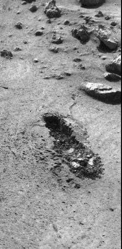
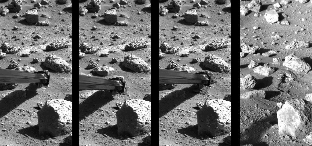
This image, received today, shows the trench excavated by NASA's Viking 1 surface sampler. The trench was dug by extending the surface sampler collection head in a direction from lower right toward the upper left and then withdrawing the surface sampler collector head. Lumpy piles of material at end of trench at lower right was pulled by plowing from trench by the backhoe which will be used to dig trenches later in the mission. Area around trench has ripple marks produced by Martian wind. The trench which was dug early on Sol 8, is about 3 inches wide, 2 inches deep and 6 inches long. Steep dark crater walls show the grains of the Martian surface material stick together (have adhesion). The doming of the surface at far end of the trench show the granular material is dense. The Martian surface material behaves somewhat like moist sand on Earth. Evidence from the trench indicate a sample was collected and delivered to the experiments after repeated tries. The biology experiment level full indicator indicates a sample was received for analysis. The X-Ray fluorescence experiment has no indication to show it received a sample. The GCMS experiment level full indicator suggests no sample was received but this matter is being investigated. http://photojournal.jpl.nasa.gov/catalog/PIA00389
The journey back to Mars begins with a liftoff of the Mars Global Surveyor atop a Delta II 7925A expendable launch vehicle from the Cape Canaveral Air Station. After an approximate 10-month interplanetary odyssey, the spacecraft will arrive at Mars and begin a 4-month aerobreaking phase, an irnovative technique first demonstrated during the Magellan mission to Venus, to achieve a mapping orbit. It will take about 2 Earth years for Surveyor to circle above most of the planet, its suite of sophisticated remote-sensing instruments building a comprehensive global portrait of Mars by mapping its topography, magnetism, mineral composition and atmosphere. Among the locations the Surveyor will pass over are the landing sites where the two U.S. Viking landers have stood since 1975 as silent monuments to the most recent successful U.S. missions to Mars. The Global Surveyor is the first of a trio of spacecraft being launched to Mars; next is Russia's Mars `96 spacecraft, followed by the U.S.'s Mars Pathfinder.
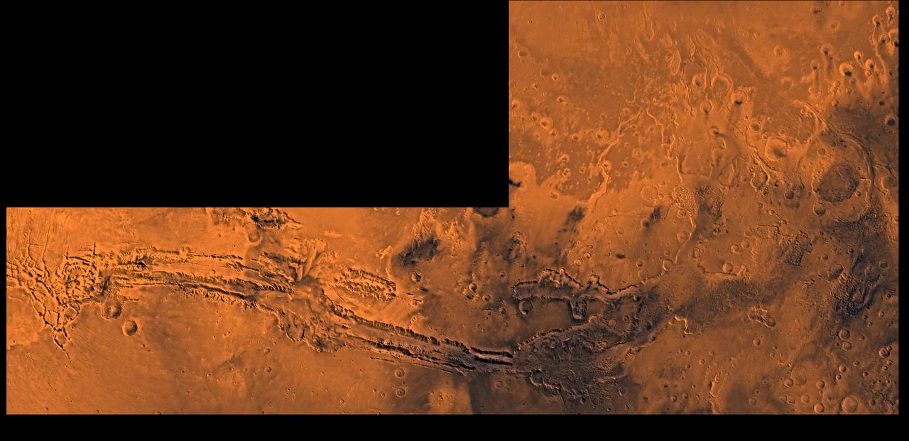
A color image of Valles Marineris, the great canyon and the south Chryse basin-Valles Marineris outflow channels of Mars; north toward top. The scene shows the entire Valles Marineris canyon system, over 3,000 km long and averaging 8 km deep, extending from Noctis Labyrinthus, the arcuate system of graben to the west, to the chaotic terrain to the east and related outflow canyons that drain toward the Chryse basin. Eos and Capri Chasmata (south to north) are two canyons connected to Valles Marineris. Ganges Chasma lies directly north. The chaos in the southeast part of the image gives rise to several outflow channels, Shalbatana, Simud, Tiu, and Ares Valles (left to right), that drained north into the Chryse basin. The mouth of Ares Valles is the site of the Mars Pathfinder lander. This image is a composite of Viking medium-resolution images in black and white and low-resolution images in color; Mercator projection. The image roughly extends from latitude 20 degrees S. to 20 degrees N. and from longitude 15 degrees to 102.5 degrees. The connected chasma or valleys of Valles Marineris may have formed from a combination of erosional collapse and structural activity. Layers of material in the eastern canyons might consist of carbonates deposited in ancient lakes, eolian deposits, or volcanic materials. Huge ancient river channels began from Valles Marineris and from adjacent canyons and ran north. Many of the channels flowed north into Chryse Basin. The south Chryse outflow channels are cut an average of 1 km into the cratered highland terrain. This terrain is about 9 km above datum near Valles Marineris and steadily decreases in elevation to 1 km below datum in the Chryse basin. Shalbatana is relatively narrow (10 km wide) but can reach 3 km in depth. The channel begins at a 2- to 3-km-deep circular depression within a large impact crater, whose floor is partly covered by chaotic material, and ends in Simud Valles. Tiu and Simud Valles consist of a complex of connected channel floors and chaotic terrain and extend as far south as and connect to eastern Valles Marineris. Ares Vallis originates from discontinuous patches of chaotic terrain within large craters. In the Chryse basin the Ares channel forks; one branch continues northwest into central Chryse Planitia and the other extends north into eastern Chryse Planitia. http://photojournal.jpl.nasa.gov/catalog/PIA00426