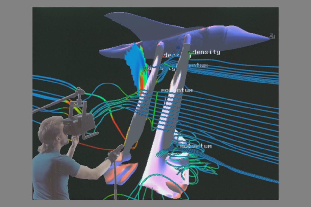
Virtual Wind Tunnel, Shuttle composite with Steve Bryson
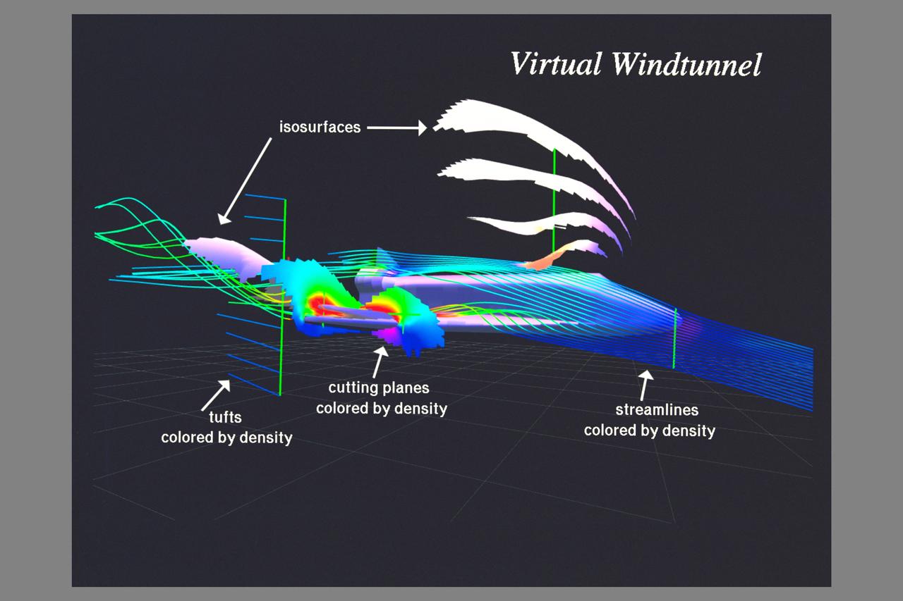
Computational Fluid Dynamics (CFD) image of Space Shuttle Pressure Flow using Virtual Wind Tunnel
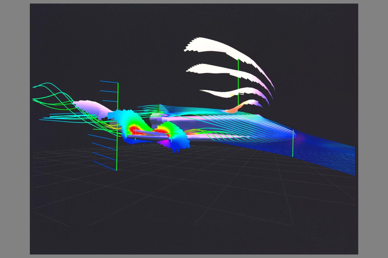
Computational Fluid Dynamics (CFD) image of Space Shuttle Pressure Flow using Virtual Wind Tunnel
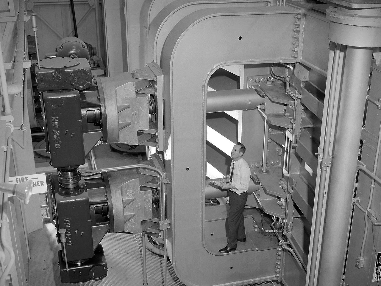
Screwjacks located on the exterior of the second throat section in the 10- by 10-Foot Supersonic Wind Tunnel at the National Aeronautics and Space Administration (NASA) Lewis Research Center. The 10- by 10 tunnel was the most powerful propulsion wind tunnel in the country when it began operating in 1956. The facility can generate wind speeds from Mach 3 to 3.5. A flexible wall nozzle located just upstream from the test section can be adjusted using screw jacks to produce the desired air flow. The 61-foot long second throat, seen here from the outside, was located just beyond the test section. It slows the supersonic air flow down to prevent shock waves. The second throat’s side walls can be adjusted up to three inches on each side using these electrically-driven screwjacks. The air and the 1.25-inch thick walls are cooled by water injection. During the 1960s the 10- by 10-foot tunnel supported the development of virtually all US launch vehicle systems. It was used for Atlas-Centaur, Saturn rockets, and Atlas-Agena testing.
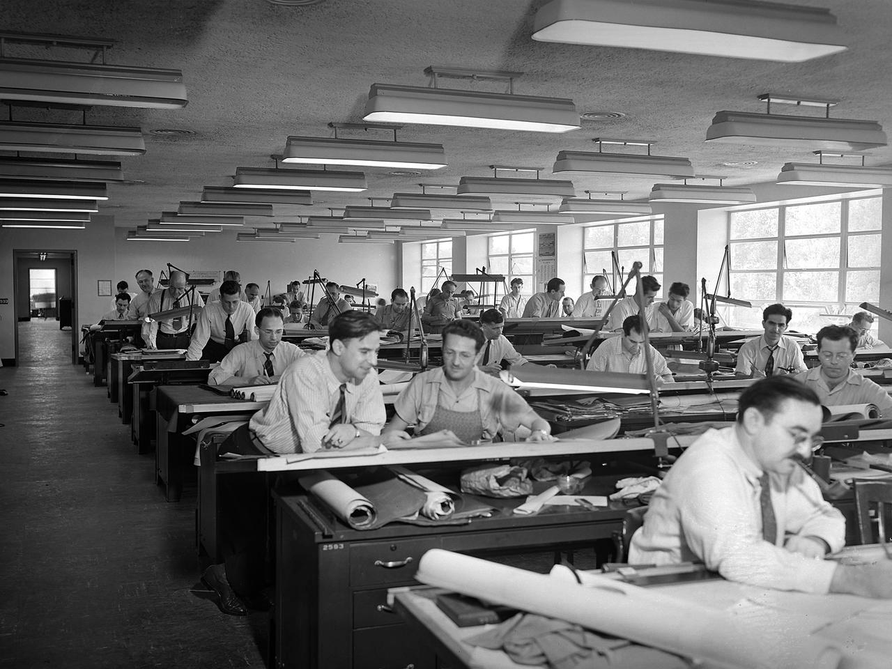
The National Advisory Committee for Aeronautics (NACA) Aircraft Engine Research Laboratory was designed by a group of engineers at the Langley Memorial Aeronautical Laboratory in late 1940 and 1941. Under the guidance of Ernest Whitney, the men worked on drawings and calculations in a room above Langley’s Structural Research Laboratory. The main Aircraft Engine Research Laboratory design group originally consisted of approximately 30 engineers and draftsmen, but there were smaller groups working separately on specific facilities. The new engine lab would have six principal buildings: the Engine Research Building, hangar, Fuels and Lubricants Building, Administration Building, Propeller Test Stand, and Altitude Wind Tunnel. In December 1941 most of those working on the project transferred to Cleveland from Langley. Harrison Underwood and Charles Egan led 18 architectural, 26 machine equipment, 3 structural and 10 mechanical draftsmen. Initially these staff members were housed in temporary offices in the hangar. As sections of the four-acre Engine Research Building were completed in the summer of 1942, the design team began relocating there. The Engine Research Building contained a variety of test cells and laboratories to address virtually every aspect of piston engine research. It also contained a two-story office wing, seen in this photograph that would later house many of the powerplant research engineers.