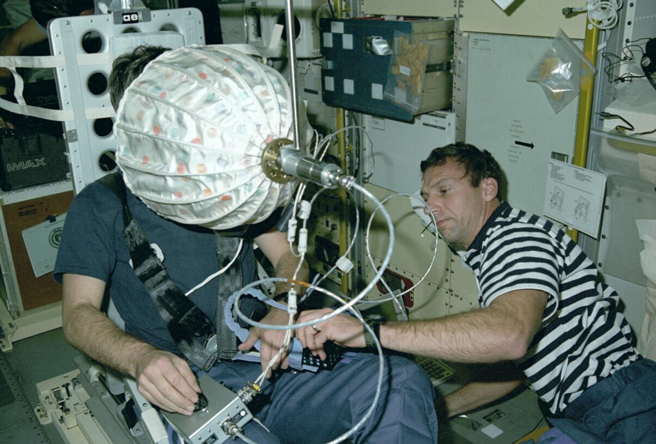
Astronaut Ulf Merbold on the stationary seat of the mini-sled, stares into an umbrella-shaped rotating dome with colored dots. Astronaut Merbold, assisted by astronaut David Hilmer, are conducting the Visual Simulator Experiment, a space physiology experiment. The Visual Stimulator Experiment measures the relative importance of visual and vestibular information in determining body orientation. When a person looks at a rotating visual field, a false sensation of self-rotation, called circularvection, results. In weightlessness, circularvection should increase immediately and may continue to increase as the nervous system comes to rely more on visual than vestibular cues. As Astronaut Merbold stares into the rotating dome with a pattern of colored dots and its interior, he turns a knob to indicate his perception of body rotation. The strength of circularvection is calculated by comparing signals from the dome and the knob. The greater the false sense of circularvection, the more the subject is relying on visual information instead of otolith information. The IML-1 mission was the first in a series of Shuttle flights dedicated to fundamental materials and life sciences research with the international partners. The participating space agencies included: NASA, the 14-nation European Space Agency (ESA), the Canadian Space Agency (CSA), the French National Center of Space Studies (CNES), the German Space Agency and the German Aerospace Research Establishment (DAR/DLR), and the National Space Development Agency of Japan (NASDA). Managed by the Marshall Space Flight Center, IML-1 was launched on January 22, 1992 aboard the Space Shuttle Orbiter Discovery (STS-42 mission).
![Astronaut Charles Conrad at the controls of the Visual Docking Simulator. From A.W. Vogeley, "Piloted Space-Flight Simulation at Langley Research Center," paper presented at the American Society of Mechanical Engineers 1966 Winter Meeting, New York, NY, November 27-December 1, 1966. "This facility was [later known as the Visual-Optical Simulator.] It presents to the pilot an out-the-window view of his target in correct 6 degrees of freedom motion. The scene is obtained by a television camera pick-up viewing a small-scale gimbaled model of the target." "For docking studies, the docking target picture was projected onto the surface of a 20-foot-diameter sphere and the pilot could, effectively, maneuver into contract. this facility was used in a comparison study with the Rendezvous Docking Simulator - one of the few comparison experiments in which conditions were carefully controlled and a reasonable sample of pilots used. All pilots preferred the more realistic RDS visual scene. The pilots generally liked the RDS angular motion cues although some objected to the false gravity cues that these motions introduced. Training time was shorter on the RDS, but final performance on both simulators was essentially equal. " "For station-keeping studies, since close approach is not required, the target was presented to the pilot through a virtual-image system which projects his view to infinity, providing a more realistic effect. In addition to the target, the system also projects a star and horizon background. "](https://images-assets.nasa.gov/image/LRC-1963-B701_P-09519/LRC-1963-B701_P-09519~medium.jpg)
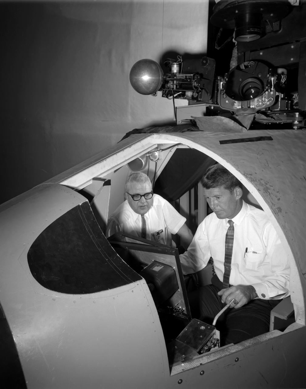
Astronaut Charles Conrad at the controls of the Visual Docking Simulator. From A.W. Vogeley, "Piloted Space-Flight Simulation at Langley Research Center," paper presented at the American Society of Mechanical Engineers 1966 Winter Meeting, New York, NY, November 27-December 1, 1966. "This facility was [later known as the Visual-Optical Simulator.] It presents to the pilot an out-the-window view of his target in correct 6 degrees of freedom motion. The scene is obtained by a television camera pick-up viewing a small-scale gimbaled model of the target." "For docking studies, the docking target picture was projected onto the surface of a 20-foot-diameter sphere and the pilot could, effectively, maneuver into contract. this facility was used in a comparison study with the Rendezvous Docking Simulator - one of the few comparison experiments in which conditions were carefully controlled and a reasonable sample of pilots used. All pilots preferred the more realistic RDS visual scene. The pilots generally liked the RDS angular motion cues although some objected to the false gravity cues that these motions introduced. Training time was shorter on the RDS, but final performance on both simulators was essentially equal. " "For station-keeping studies, since close approach is not required, the target was presented to the pilot through a virtual-image system which projects his view to infinity, providing a more realistic effect. In addition to the target, the system also projects a star and horizon background. "
Walter (Wally) M. Schirra in Visual Docking Simulator From A.W. Vogeley, "Piloted Space-Flight Simulation at Langley Research Center," Paper presented at the American Society of Mechanical Engineers 1966 Winter Meeting, New York, NY, November 27-December 1, 1966. "This facility was [later known as the Visual-Optical Simulator. It presents to the pilot an out-the-window view of his target in correct 6 degrees of freedom motion. The scene is obtained by a television camera pick-up viewing a small-scale gimbaled model of the target. "For docking studies, the docking target picture was projected onto the surface of a 20-foot-diameter sphere and the pilot could, effectively, maneuver into contract. this facility was used in a comparison study with the Rendezvous Docking Simulator - one of the few comparison experiments in which conditions were carefully controlled and a reasonable sample of pilots used. All pilots preferred the more realistic RDS visual scene. The pilots generally liked the RDS angular motion cues although some objected to the false gravity cues that these motions introduced. Training time was shorter on the RDS, but final performance on both simulators was essentially equal. " "For station-keeping studies, since close approach is not required, the target was presented to the pilot through a virtual-image system which projects his view to infinity, providing a more realistic effect. In addition to the target, the system also projects a star and horizon background. "
![Astronauts Charles Conrad (left) and John W. Young (right) at the controls of the Visual Docking Simulator. From A.W. Vogeley, "Piloted Space-Flight Simulation at Langley Research Center," Paper presented at the American Society of Mechanical Engineers 1966 Winter Meeting, New York, NY, November 27-December 1, 1966. "This facility was [later known as the Visual-Optical Simulator.] It presents to the pilot an out-the-window view of his target in correct 6 degrees of freedom motion. The scene is obtained by a television camera pick-up viewing a small-scale gimbaled model of the target." "For docking studies, the docking target picture was projected onto the surface of a 20-foot-diameter sphere and the pilot could, effectively, maneuver into contract. this facility was used in a comparison study with the Rendezvous Docking Simulator - one of the few comparison experiments in which conditions were carefully controlled and a reasonable sample of pilots used. All pilots preferred the more realistic RDS visual scene. The pilots generally liked the RDS angular motion cues although some objected to the false gravity cues that these motions introduced. Training time was shorter on the RDS, but final performance on both simulators was essentially equal. " "For station-keeping studies, since close approach is not required, the target was presented to the pilot through a virtual-image system which projects his view to infinity, providing a more realistic effect. In addition to the target, the system also projects a star and horizon background. "](https://images-assets.nasa.gov/image/LRC-1963-B701_P-09520/LRC-1963-B701_P-09520~medium.jpg)
Astronauts Charles Conrad (left) and John W. Young (right) at the controls of the Visual Docking Simulator. From A.W. Vogeley, "Piloted Space-Flight Simulation at Langley Research Center," Paper presented at the American Society of Mechanical Engineers 1966 Winter Meeting, New York, NY, November 27-December 1, 1966. "This facility was [later known as the Visual-Optical Simulator.] It presents to the pilot an out-the-window view of his target in correct 6 degrees of freedom motion. The scene is obtained by a television camera pick-up viewing a small-scale gimbaled model of the target." "For docking studies, the docking target picture was projected onto the surface of a 20-foot-diameter sphere and the pilot could, effectively, maneuver into contract. this facility was used in a comparison study with the Rendezvous Docking Simulator - one of the few comparison experiments in which conditions were carefully controlled and a reasonable sample of pilots used. All pilots preferred the more realistic RDS visual scene. The pilots generally liked the RDS angular motion cues although some objected to the false gravity cues that these motions introduced. Training time was shorter on the RDS, but final performance on both simulators was essentially equal. " "For station-keeping studies, since close approach is not required, the target was presented to the pilot through a virtual-image system which projects his view to infinity, providing a more realistic effect. In addition to the target, the system also projects a star and horizon background. "
![Astronaut James Lovell at the controls of the Visual Docking Simulator. From A.W. Vogeley, "Piloted Space-Flight Simulation at Langley Research Center," Paper presented at the American Society of Mechanical Engineers 1966 Winter Meeting, New York, NY, November 27-December 1, 1966. "This facility was [later known as the Visual-Optical Simulator.] It presents to the pilot an out-the-window view of his target in correct 6 degrees of freedom motion. The scene is obtained by a television camera pick-up viewing a small-scale gimbaled model of the target." "For docking studies, the docking target picture was projected onto the surface of a 20-foot-diameter sphere and the pilot could, effectively, maneuver into contract. this facility was used in a comparison study with the Rendezvous Docking Simulator - one of the few comparison experiments in which conditions were carefully controlled and a reasonable sample of pilots used. All pilots preferred the more realistic RDS visual scene. The pilots generally liked the RDS angular motion cues although some objected to the false gravity cues that these motions introduced. Training time was shorter on the RDS, but final performance on both simulators was essentially equal. " "For station-keeping studies, since close approach is not required, the target was presented to the pilot through a virtual-image system which projects his view to infinity, providing a more realistic effect. In addition to the target, the system also projects a star and horizon background. "](https://images-assets.nasa.gov/image/LRC-1963-B701_P-09093/LRC-1963-B701_P-09093~medium.jpg)
Astronaut James Lovell at the controls of the Visual Docking Simulator. From A.W. Vogeley, "Piloted Space-Flight Simulation at Langley Research Center," Paper presented at the American Society of Mechanical Engineers 1966 Winter Meeting, New York, NY, November 27-December 1, 1966. "This facility was [later known as the Visual-Optical Simulator.] It presents to the pilot an out-the-window view of his target in correct 6 degrees of freedom motion. The scene is obtained by a television camera pick-up viewing a small-scale gimbaled model of the target." "For docking studies, the docking target picture was projected onto the surface of a 20-foot-diameter sphere and the pilot could, effectively, maneuver into contract. this facility was used in a comparison study with the Rendezvous Docking Simulator - one of the few comparison experiments in which conditions were carefully controlled and a reasonable sample of pilots used. All pilots preferred the more realistic RDS visual scene. The pilots generally liked the RDS angular motion cues although some objected to the false gravity cues that these motions introduced. Training time was shorter on the RDS, but final performance on both simulators was essentially equal. " "For station-keeping studies, since close approach is not required, the target was presented to the pilot through a virtual-image system which projects his view to infinity, providing a more realistic effect. In addition to the target, the system also projects a star and horizon background. "
![Astronaut James Lovell at the controls of the Visual Docking Simulator. From A.W. Vogeley, "Piloted Space-Flight Simulation at Langley Research Center," Paper presented at the American Society of Mechanical Engineers 1966 Winter Meeting, New York, NY, November 27-December 1, 1966. "This facility was [later known as the Visual-Optical Simulator.] It presents to the pilot an out-the-window view of his target in correct 6 degrees of freedom motion. The scene is obtained by a television camera pick-up viewing a small-scale gimbaled model of the target." "For docking studies, the docking target picture was projected onto the surface of a 20-foot-diameter sphere and the pilot could, effectively, maneuver into contract. this facility was used in a comparison study with the Rendezvous Docking Simulator - one of the few comparison experiments in which conditions were carefully controlled and a reasonable sample of pilots used. All pilots preferred the more realistic RDS visual scene. The pilots generally liked the RDS angular motion cues although some objected to the false gravity cues that these motions introduced. Training time was shorter on the RDS, but final performance on both simulators was essentially equal. " "For station-keeping studies, since close approach is not required, the target was presented to the pilot through a virtual-image system which projects his view to infinity, providing a more realistic effect. In addition to the target, the system also projects a star and horizon background. "](https://images-assets.nasa.gov/image/LRC-1963-B701_P-09094/LRC-1963-B701_P-09094~medium.jpg)
Astronaut James Lovell at the controls of the Visual Docking Simulator. From A.W. Vogeley, "Piloted Space-Flight Simulation at Langley Research Center," Paper presented at the American Society of Mechanical Engineers 1966 Winter Meeting, New York, NY, November 27-December 1, 1966. "This facility was [later known as the Visual-Optical Simulator.] It presents to the pilot an out-the-window view of his target in correct 6 degrees of freedom motion. The scene is obtained by a television camera pick-up viewing a small-scale gimbaled model of the target." "For docking studies, the docking target picture was projected onto the surface of a 20-foot-diameter sphere and the pilot could, effectively, maneuver into contract. this facility was used in a comparison study with the Rendezvous Docking Simulator - one of the few comparison experiments in which conditions were carefully controlled and a reasonable sample of pilots used. All pilots preferred the more realistic RDS visual scene. The pilots generally liked the RDS angular motion cues although some objected to the false gravity cues that these motions introduced. Training time was shorter on the RDS, but final performance on both simulators was essentially equal. " "For station-keeping studies, since close approach is not required, the target was presented to the pilot through a virtual-image system which projects his view to infinity, providing a more realistic effect. In addition to the target, the system also projects a star and horizon background. "
![Astronaut Virgil "Gus" Grissom at the controls of the Visual Docking Simulator. From A.W. Vogeley, "Piloted Space-Flight Simulation at Langley Research Center," Paper presented at the American Society of Mechanical Engineers 1966 Winter Meeting, New York, NY, November 27-December 1, 1966. "This facility was [later known as the Visual-Optical Simulator.] It presents to the pilot an out-the-window view of his target in correct 6 degrees of freedom motion. The scene is obtained by a television camera pick-up viewing a small-scale gimbaled model of the target." "For docking studies, the docking target picture was projected onto the surface of a 20-foot-diameter sphere and the pilot could, effectively, maneuver into contract. this facility was used in a comparison study with the Rendezvous Docking Simulator - one of the few comparison experiments in which conditions were carefully controlled and a reasonable sample of pilots used. All pilots preferred the more realistic RDS visual scene. The pilots generally liked the RDS angular motion cues although some objected to the false gravity cues that these motions introduced. Training time was shorter on the RDS, but final performance on both simulators was essentially equal. " "For station-keeping studies, since close approach is not required, the target was presented to the pilot through a virtual-image system which projects his view to infinity, providing a more realistic effect. In addition to the target, the system also projects a star and horizon background. "](https://images-assets.nasa.gov/image/LRC-1963-B701_P-01515/LRC-1963-B701_P-01515~medium.jpg)
Astronaut Virgil "Gus" Grissom at the controls of the Visual Docking Simulator. From A.W. Vogeley, "Piloted Space-Flight Simulation at Langley Research Center," Paper presented at the American Society of Mechanical Engineers 1966 Winter Meeting, New York, NY, November 27-December 1, 1966. "This facility was [later known as the Visual-Optical Simulator.] It presents to the pilot an out-the-window view of his target in correct 6 degrees of freedom motion. The scene is obtained by a television camera pick-up viewing a small-scale gimbaled model of the target." "For docking studies, the docking target picture was projected onto the surface of a 20-foot-diameter sphere and the pilot could, effectively, maneuver into contract. this facility was used in a comparison study with the Rendezvous Docking Simulator - one of the few comparison experiments in which conditions were carefully controlled and a reasonable sample of pilots used. All pilots preferred the more realistic RDS visual scene. The pilots generally liked the RDS angular motion cues although some objected to the false gravity cues that these motions introduced. Training time was shorter on the RDS, but final performance on both simulators was essentially equal. " "For station-keeping studies, since close approach is not required, the target was presented to the pilot through a virtual-image system which projects his view to infinity, providing a more realistic effect. In addition to the target, the system also projects a star and horizon background. "
![Astronaut Virgil "Gus" Grissom at the controls of the Visual Docking Simulator. From A.W. Vogeley, "Piloted Space-Flight Simulation at Langley Research Center," Paper presented at the American Society of Mechanical Engineers 1966 Winter Meeting, New York, NY, November 27-December 1, 1966. "This facility was [later known as the Visual-Optical Simulator.] It presents to the pilot an out-the-window view of his target in correct 6 degrees of freedom motion. The scene is obtained by a television camera pick-up viewing a small-scale gimbaled model of the target." "For docking studies, the docking target picture was projected onto the surface of a 20-foot-diameter sphere and the pilot could, effectively, maneuver into contract. this facility was used in a comparison study with the Rendezvous Docking Simulator - one of the few comparison experiments in which conditions were carefully controlled and a reasonable sample of pilots used. All pilots preferred the more realistic RDS visual scene. The pilots generally liked the RDS angular motion cues although some objected to the false gravity cues that these motions introduced. Training time was shorter on the RDS, but final performance on both simulators was essentially equal. " "For station-keeping studies, since close approach is not required, the target was presented to the pilot through a virtual-image system which projects his view to infinity, providing a more realistic effect. In addition to the target, the system also projects a star and horizon background. "](https://images-assets.nasa.gov/image/LRC-1963-B701_P-01516/LRC-1963-B701_P-01516~medium.jpg)
Astronaut Virgil "Gus" Grissom at the controls of the Visual Docking Simulator. From A.W. Vogeley, "Piloted Space-Flight Simulation at Langley Research Center," Paper presented at the American Society of Mechanical Engineers 1966 Winter Meeting, New York, NY, November 27-December 1, 1966. "This facility was [later known as the Visual-Optical Simulator.] It presents to the pilot an out-the-window view of his target in correct 6 degrees of freedom motion. The scene is obtained by a television camera pick-up viewing a small-scale gimbaled model of the target." "For docking studies, the docking target picture was projected onto the surface of a 20-foot-diameter sphere and the pilot could, effectively, maneuver into contract. this facility was used in a comparison study with the Rendezvous Docking Simulator - one of the few comparison experiments in which conditions were carefully controlled and a reasonable sample of pilots used. All pilots preferred the more realistic RDS visual scene. The pilots generally liked the RDS angular motion cues although some objected to the false gravity cues that these motions introduced. Training time was shorter on the RDS, but final performance on both simulators was essentially equal. " "For station-keeping studies, since close approach is not required, the target was presented to the pilot through a virtual-image system which projects his view to infinity, providing a more realistic effect. In addition to the target, the system also projects a star and horizon background. "
![Astronaut Frank Borman at the controls of the Visual Docking Simulator. From A.W. Vogeley, "Piloted Space-Flight Simulation at Langley Research Center," Paper presented at the American Society of Mechanical Engineers 1966 Winter Meeting, New York, NY, November 27-December 1, 1966. "This facility was [later known as the Visual-Optical Simulator.] It presents to the pilot an out-the-window view of his target in correct 6 degrees of freedom motion. The scene is obtained by a television camera pick-up viewing a small-scale gimbaled model of the target." "For docking studies, the docking target picture was projected onto the surface of a 20-foot-diameter sphere and the pilot could, effectively, maneuver into contract. this facility was used in a comparison study with the Rendezvous Docking Simulator - one of the few comparison experiments in which conditions were carefully controlled and a reasonable sample of pilots used. All pilots preferred the more realistic RDS visual scene. The pilots generally liked the RDS angular motion cues although some objected to the false gravity cues that these motions introduced. Training time was shorter on the RDS, but final performance on both simulators was essentially equal. " "For station-keeping studies, since close approach is not required, the target was presented to the pilot through a virtual-image system which projects his view to infinity, providing a more realistic effect. In addition to the target, the system also projects a star and horizon background. "](https://images-assets.nasa.gov/image/LRC-1963-B701_P-09368/LRC-1963-B701_P-09368~medium.jpg)
Astronaut Frank Borman at the controls of the Visual Docking Simulator. From A.W. Vogeley, "Piloted Space-Flight Simulation at Langley Research Center," Paper presented at the American Society of Mechanical Engineers 1966 Winter Meeting, New York, NY, November 27-December 1, 1966. "This facility was [later known as the Visual-Optical Simulator.] It presents to the pilot an out-the-window view of his target in correct 6 degrees of freedom motion. The scene is obtained by a television camera pick-up viewing a small-scale gimbaled model of the target." "For docking studies, the docking target picture was projected onto the surface of a 20-foot-diameter sphere and the pilot could, effectively, maneuver into contract. this facility was used in a comparison study with the Rendezvous Docking Simulator - one of the few comparison experiments in which conditions were carefully controlled and a reasonable sample of pilots used. All pilots preferred the more realistic RDS visual scene. The pilots generally liked the RDS angular motion cues although some objected to the false gravity cues that these motions introduced. Training time was shorter on the RDS, but final performance on both simulators was essentially equal. " "For station-keeping studies, since close approach is not required, the target was presented to the pilot through a virtual-image system which projects his view to infinity, providing a more realistic effect. In addition to the target, the system also projects a star and horizon background. "
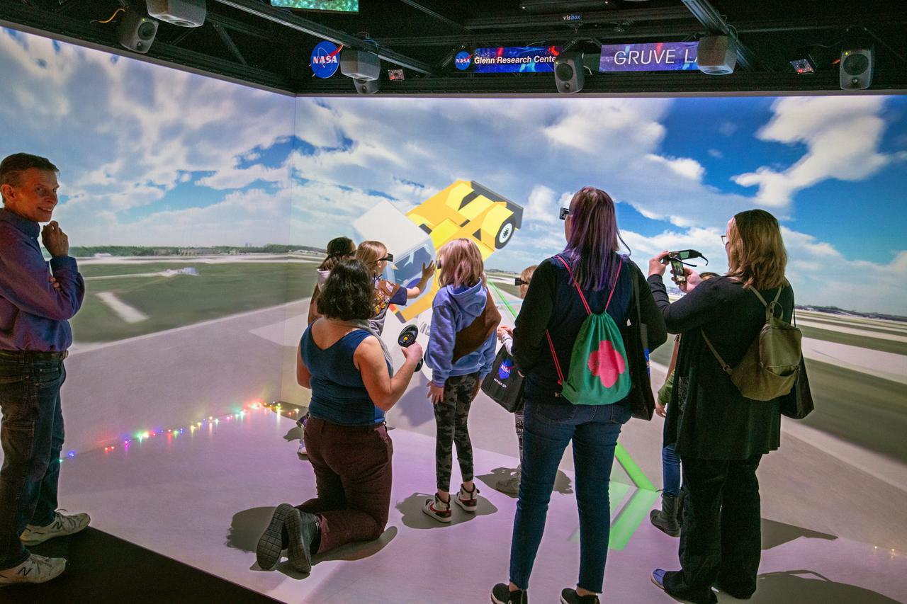
Local area girl scouts competed in a "Girl Scouts to the Moon and Back" essay contest. The essay contest gave the girls scouts a chance to win a Space Science badge that has actually been to space on NASA's Artemis I mission. After the award ceremony the girl scouts got to tour some of the NASA Glenn facilities. Picture is the "cave" at the Graphics and Visualization Lab, also known as the GRUVE Lab. Looking on is Richard Rinehart who is an engineer who works in the GRUVE LAB and creates 3D simulated experiences that demonstrate NASA's technology.
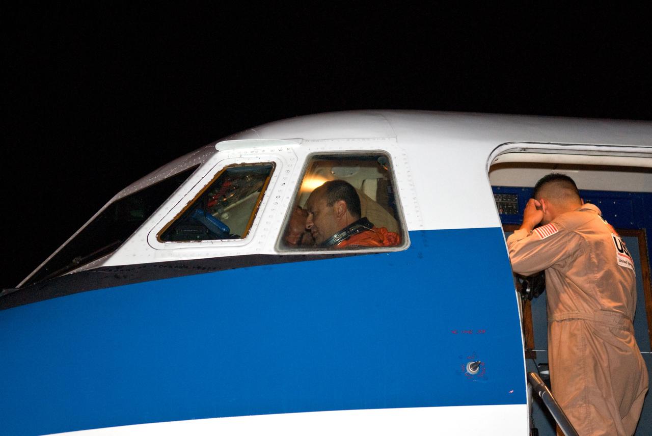
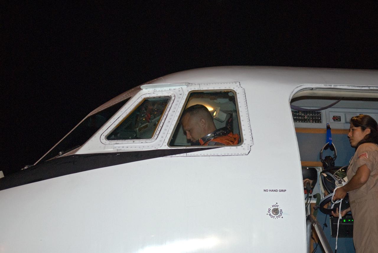
CAPE CANAVERAL, Fla. – At the Shuttle Landing Facility at NASA's Kennedy Space Center in Florida, STS-127 Commander Mark Polansky checks cockpit controls seated in the Shuttle Training Aircraft. Polansky will fly the STA to practice landings in preparation for launch of space shuttle Endeavour on the STS-127 mission on June 13 to the International Space Station. The STA is a Grumman American Aviation-built Gulfstream II jet that was modified to simulate a shuttle’s cockpit, motion and visual cues, and handling qualities. Endeavour will deliver the Japanese Experiment Module's Exposed Facility, or JEM-EF, and the Experiment Logistics Module-Exposed Section, or ELM-ES. on STS-127. The mission is the final of three flights dedicated to the assembly of the Japan Aerospace Exploration Agency's Kibo laboratory complex on the space station. Photo credit: NASA/Kim Shiflett
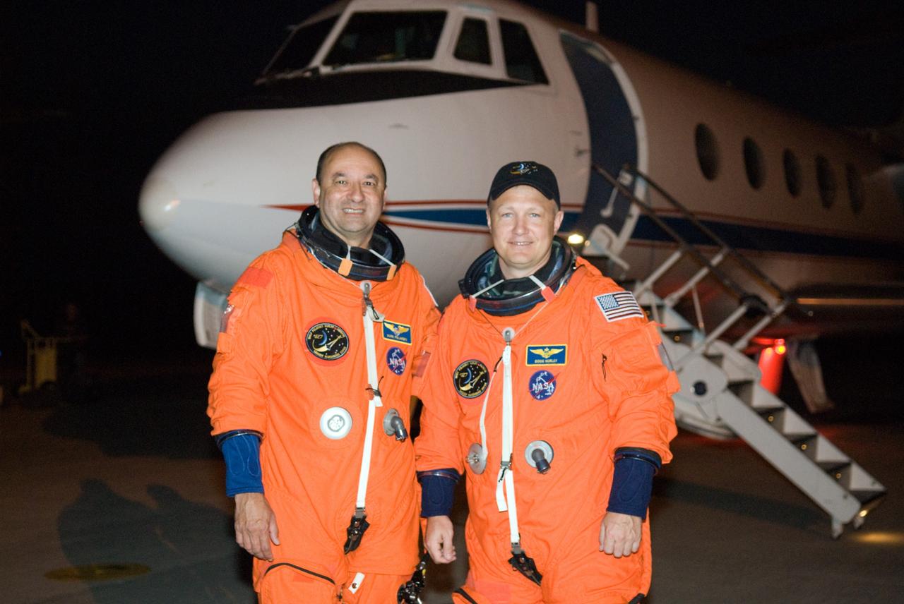
CAPE CANAVERAL, Fla. – At the Shuttle Landing Facility at NASA's Kennedy Space Center in Florida, STS-127 Commander Mark Polansky and Pilot Doug Hurley are ready to begin practicing landings in the Shuttle Training Aircraft. They are practicing in preparation for launch of space shuttle Endeavour on the STS-127 mission on June 13 to the International Space Station. The STA is a Grumman American Aviation-built Gulfstream II jet that was modified to simulate a shuttle’s cockpit, motion and visual cues, and handling qualities. Endeavour will deliver the Japanese Experiment Module's Exposed Facility, or JEM-EF, and the Experiment Logistics Module-Exposed Section, or ELM-ES. on STS-127. The mission is the final of three flights dedicated to the assembly of the Japan Aerospace Exploration Agency's Kibo laboratory complex on the space station. Photo credit: NASA/Kim Shiflett
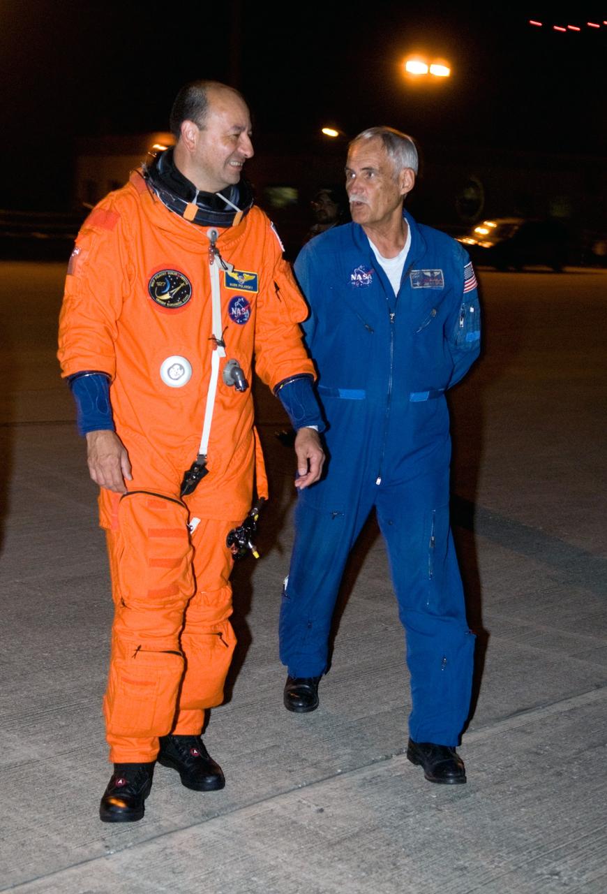
CAPE CANAVERAL, Fla. – At the Shuttle Landing Facility at NASA's Kennedy Space Center in Florida, STS-127 Commander Mark Polansky makes his way to the Shuttle Training Aircraft to practice landings in preparation for launch of space shuttle Endeavour on the STS-127 mission on June 13 to the International Space Station. The STA is a Grumman American Aviation-built Gulfstream II jet that was modified to simulate a shuttle’s cockpit, motion and visual cues, and handling qualities. Endeavour will deliver the Japanese Experiment Module's Exposed Facility, or JEM-EF, and the Experiment Logistics Module-Exposed Section, or ELM-ES. on STS-127. The mission is the final of three flights dedicated to the assembly of the Japan Aerospace Exploration Agency's Kibo laboratory complex on the space station. Photo credit: NASA/Kim Shiflett
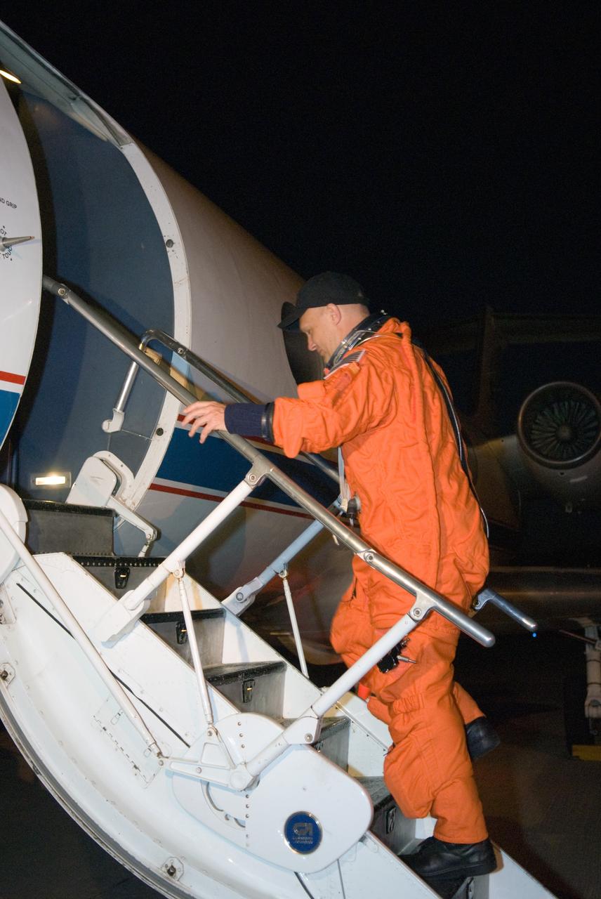
CAPE CANAVERAL, Fla. – At the Shuttle Landing Facility at NASA's Kennedy Space Center in Florida, STS-127 Pilot Doug Hurley heads into the Shuttle Training Aircraft to practice landings in preparation for launch of space shuttle Endeavour on the STS-127 mission on June 13 to the International Space Station. The STA is a Grumman American Aviation-built Gulfstream II jet that was modified to simulate a shuttle’s cockpit, motion and visual cues, and handling qualities. Endeavour will deliver the Japanese Experiment Module's Exposed Facility, or JEM-EF, and the Experiment Logistics Module-Exposed Section, or ELM-ES. on STS-127. The mission is the final of three flights dedicated to the assembly of the Japan Aerospace Exploration Agency's Kibo laboratory complex on the space station. Photo credit: NASA/Kim Shiflett
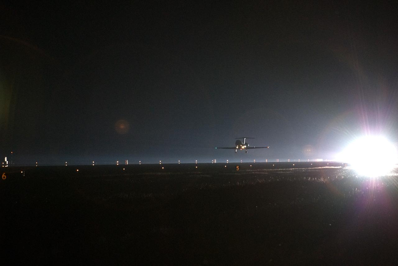
CAPE CANAVERAL, Fla. – A Shuttle Training Aircraft approaches touchdown on the runway at the Shuttle Landing Facility at NASA's Kennedy Space Center in Florida. STS-127 Commander Mark Polansky and Pilot Doug Hurley are practicing landings in the STA in preparation for launch of space shuttle Endeavour on the STS-127 mission on June 13 to the International Space Station. The STA is a Grumman American Aviation-built Gulfstream II jet that was modified to simulate a shuttle’s cockpit, motion and visual cues, and handling qualities. Endeavour will deliver the Japanese Experiment Module's Exposed Facility, or JEM-EF, and the Experiment Logistics Module-Exposed Section, or ELM-ES. on STS-127. The mission is the final of three flights dedicated to the assembly of the Japan Aerospace Exploration Agency's Kibo laboratory complex on the space station. Photo credit: NASA/Kim Shiflett
CAPE CANAVERAL, Fla. – At the Shuttle Landing Facility at NASA's Kennedy Space Center in Florida, STS-127 Pilot Doug Hurley checks cockpit controls seated in the Shuttle Training Aircraft. Hurley will fly the STA to practice landings in preparation for launch of space shuttle Endeavour on the STS-127 mission on June 13 to the International Space Station. The STA is a Grumman American Aviation-built Gulfstream II jet that was modified to simulate a shuttle’s cockpit, motion and visual cues, and handling qualities. Endeavour will deliver the Japanese Experiment Module's Exposed Facility, or JEM-EF, and the Experiment Logistics Module-Exposed Section, or ELM-ES. on STS-127. The mission is the final of three flights dedicated to the assembly of the Japan Aerospace Exploration Agency's Kibo laboratory complex on the space station. Photo credit: NASA/Kim Shiflett
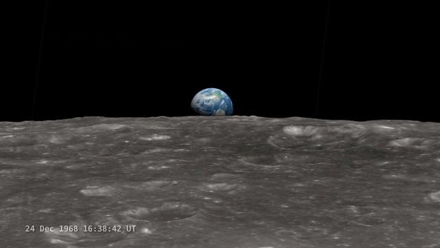
<b>Join NASA's Google+ Hangout on Friday, December 20th 2:00 - 3:00 PM (EST) at <a href="http://go.nasa.gov/18S2TbC" rel="nofollow">go.nasa.gov/18S2TbC</a> </b> It was 45 years ago, on December 24, 1968 when Apollo 8 astronauts captured 'Earthrise' – the first color photograph of Earth taken by a person in lunar orbit. NASA announces a new simulation of the events leading to the creation of 'Earthrise,' one of the iconic photographs of the 20th Century – Earth seen from the moon captured by the crew of Apollo 8. This new simulation allows anyone to virtually ride with the astronauts and experience the awe they felt at the vista in front of them. Apollo 8 Commander Frank Borman and crew members William A. Anders and James A. Lovell photographed the stunning scene as their spacecraft orbited the moon on December 24, 1968. The new computer simulation was created using data from NASA's Lunar Reconnaissance Orbiter, or LRO, spacecraft and includes details not seen in the previous visualization released last year. Participants in this Hangout include: * John Keller, project scientist for the Lunar Reconnaissance Orbiter project * Ernie Wright, project lead with the Scientific Visualization Studio at NASA Goddard Space Flight Center * Andrew Chaikin, space historian, author of the book A Man on the Moon "This will also be the first time we've released a video that's synchronized with the onboard audio recording of the astronauts,", says Ernie Wright. "The new visualization tells us not only what time the photos were taken, but also exactly which way the spacecraft was pointing and therefore which window each photo was taken from." Earthrise is the cover photo of TIME's Great Images of the 20th Century and is among photos on the cover of LIFE's 100 Photographs That Changed the World. <b><a href="http://www.nasa.gov/audience/formedia/features/MP_Photo_Guidelines.html" rel="nofollow">NASA image use policy.</a></b> <b><a href="http://www.nasa.gov/centers/goddard/home/index.html" rel="nofollow">NASA Goddard Space Flight Center</a></b> enables NASA’s mission through four scientific endeavors: Earth Science, Heliophysics, Solar System Exploration, and Astrophysics. Goddard plays a leading role in NASA’s accomplishments by contributing compelling scientific knowledge to advance the Agency’s mission. <b>Follow us on <a href="http://twitter.com/NASA_GoddardPix" rel="nofollow">Twitter</a></b> <b>Like us on <a href="http://www.facebook.com/pages/Greenbelt-MD/NASA-Goddard/395013845897?ref=tsd" rel="nofollow">Facebook</a></b> <b>Find us on <a href="http://instagram.com/nasagoddard?vm=grid" rel="nofollow">Instagram</a></b>

NASA models and supercomputing have created a colorful new view of aerosol movement. Satellites, balloon-borne instruments and ground-based devices make 30 million observations of the atmosphere each day. Yet these measurements still give an incomplete picture of the complex interactions within the membrane surrounding Earth. Enter climate models. Through mathematical experiments, modelers can move Earth forward or backward in time to create a dynamic portrait of the planet. Researchers from NASA Goddard’s Global Modeling and Assimilation Office recently ran a simulation of the atmosphere that captured how winds whip aerosols around the world. Such simulations allow scientists to better understand how these tiny particulates travel in the atmosphere and influence weather and climate. In the visualization below, covering August 2006 to April 2007, watch as dust and sea salt swirl inside cyclones, carbon bursts from fires, sulfate streams from volcanoes—and see how these aerosols paint the modeled world. Credit: NASA/Goddard Space Flight Center
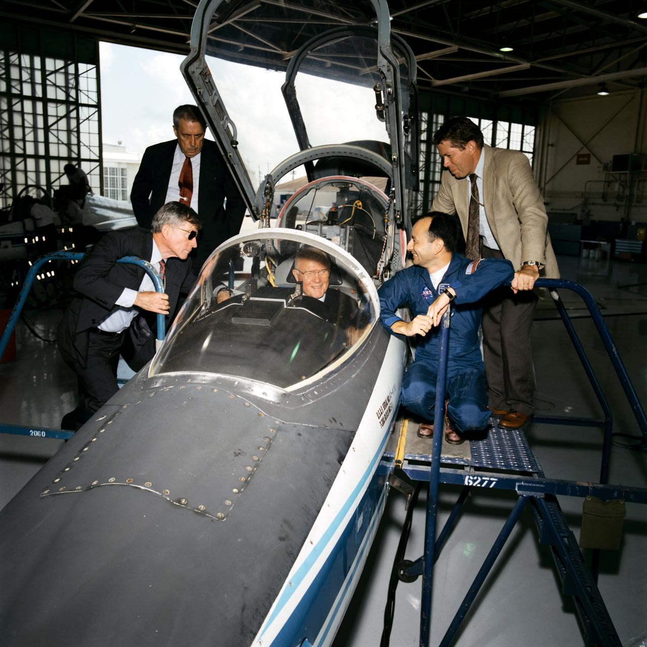
Senator John Glenn visit to Johnson Space Center (JSC). Views of Glenn sitting in cockpit of T-38 in Hangar 276 with John Young, George Abbey, David Leestma and Mark Polansky observing (11150). An engineer explains SPIFEX experiment hardware to Abby, Young and Glenn in Bldg 13 (11151, 11153). Glenn talks with astronaut Terrence T. Henricks and employees in Bldg 9C, Virtual reality lab (11152). Lunch in Bldg 17 Flight Crew support division with Dr. Ellen Baker, Robert "Hoot" Gibson and John Glenn (11154). Linda Godwin, Robert Cabana, Abbey, Young, Baker, Gibson and Glenn at lunch (11155). Astronaut Mark Lee shows Glenn and his aide how to use the virtural reality helmets (11156-7). Glenn shakes the hand of Franklin Chang-Diaz with his plasma rocket in the background in the Sonny Carter Training Facility (SCTF) (11158). Glenn in the Manipulator Development Facility (MDF) Remote Manipulator System (RMS) station mock-up in Bldg 9A with Abbey, Young and aide (11159, 11186). Glenn signs a book for Thomas D. Jones as Frederick Sturckow and Linda Godwin look on (11160). Glenn inside visual-vestibular trainer in Bldg 9B (11161). In conference room meeting with astronaut corps in Bldg 4S, Glenn shakes Robert Cabana's hand (11162). John Glenn and John Young pose for a group shot with Bldg 17 Food lab personnel (11163). Glenn thanks the food lab personnel (11164). Glenn visits Bldg 5 Fixed Base (FB) middeck simulator with astronauts Terrence Henricks and Mary Ellen Weber (11165). Glenn with Charles T. Bourland (11166). STS-70 crew Donald Thomas, Terrence Henricks, Mary Ellen Weber, Nancy Currie and Kevin Kregel with Glenn's advisor (11167). STS-70 crew Thomas, Henricks, Weber, Currie and Kregel with John Glenn (11175). Glenn with Thomas, Kregel, Weber, Henricks and trainer (11176-7). David J. Homan assists Glenn's aide with virtual reality goggles (11168) and Glenn (11174). John Young in Bldg 9C equilibrium trainer (11169). Glenn with Carl Walz in flight deck mock-up of MDF in Bldg 9NE (11170, 11187). Young, Abbey, aides, Glenn and Walz examine helium balloon in MDF (11171-2). Chang-Diaz shows Glenn's tour group the plasma rocket (11173). Glenn's presentation to astronaut corps (11178-81, 11184-5). Glenn is presented with framed picture of Sonny Carter Training Facility (SCTF) (11182) and framed picture of space station (11183).