Mercury Wings
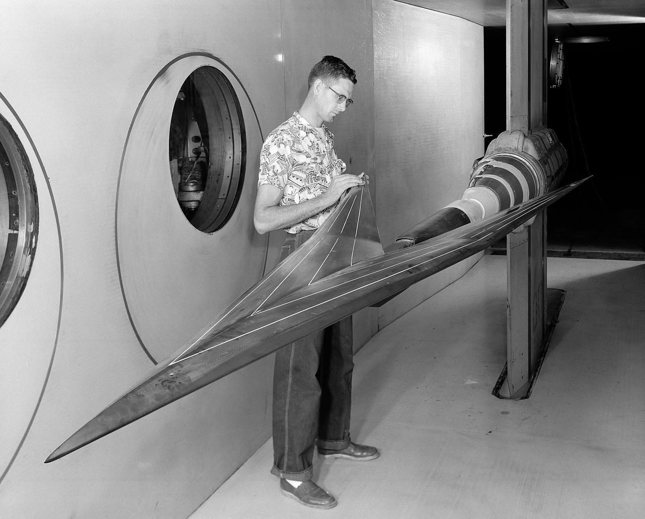
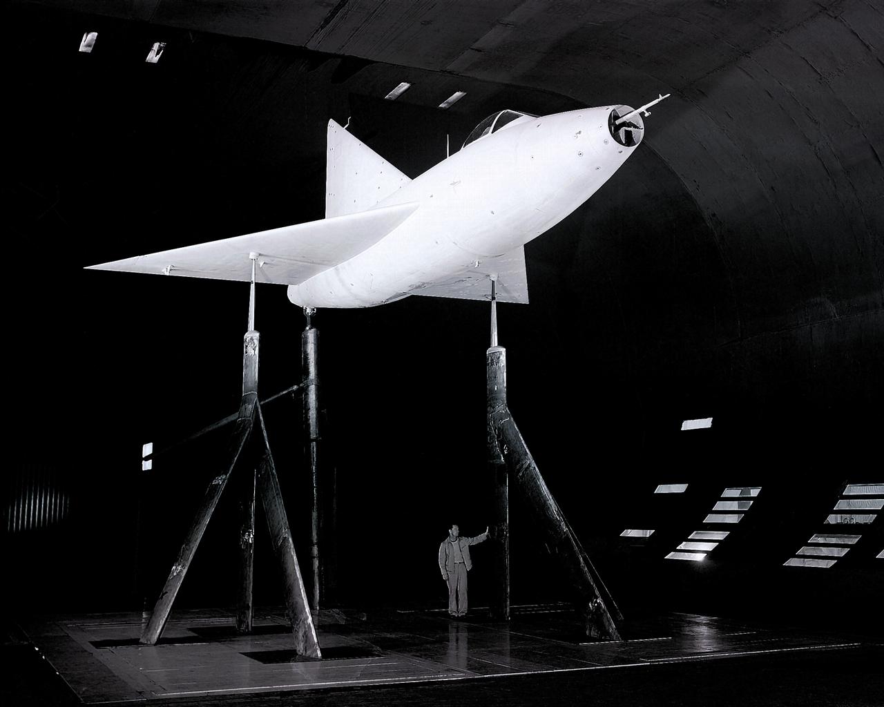
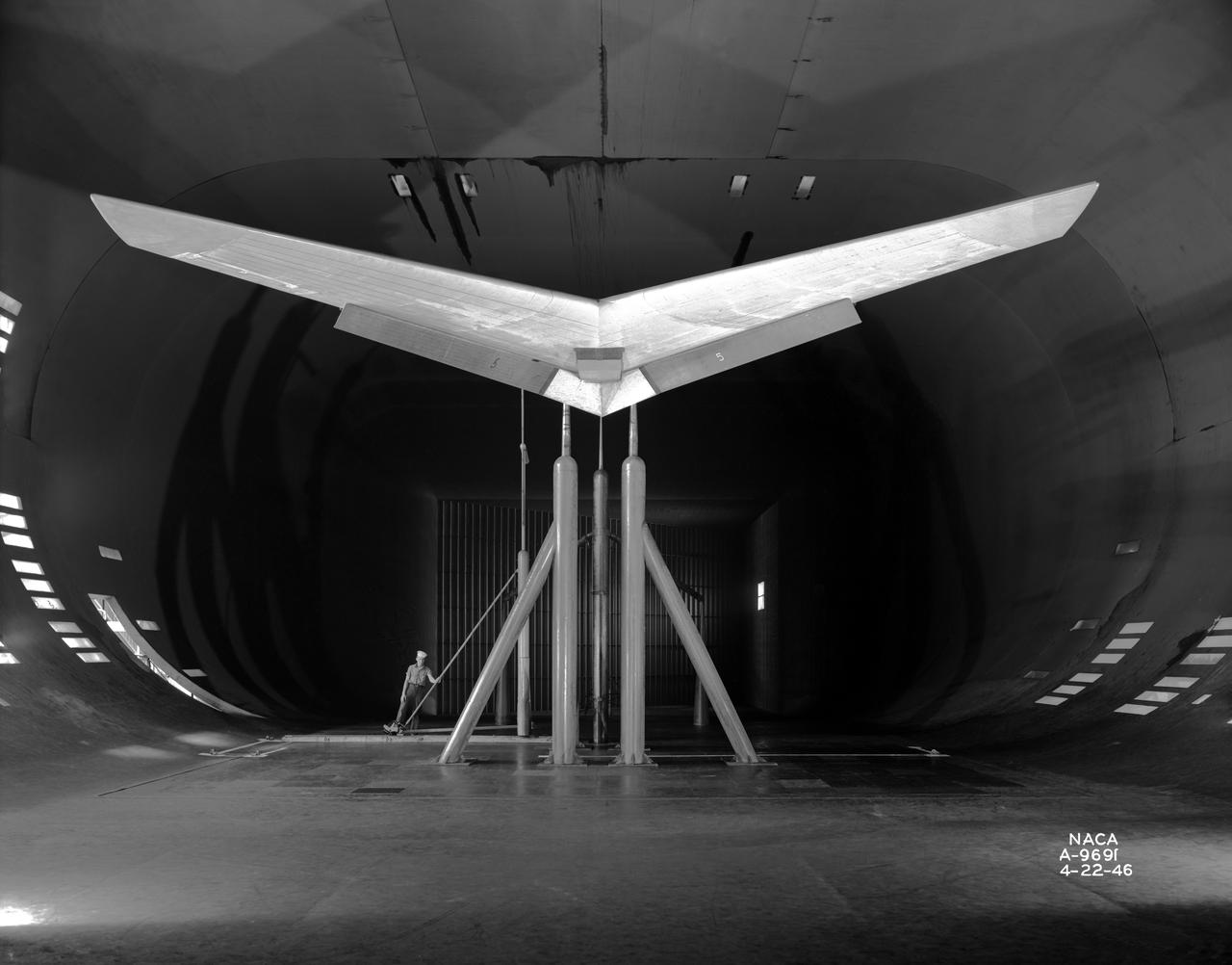
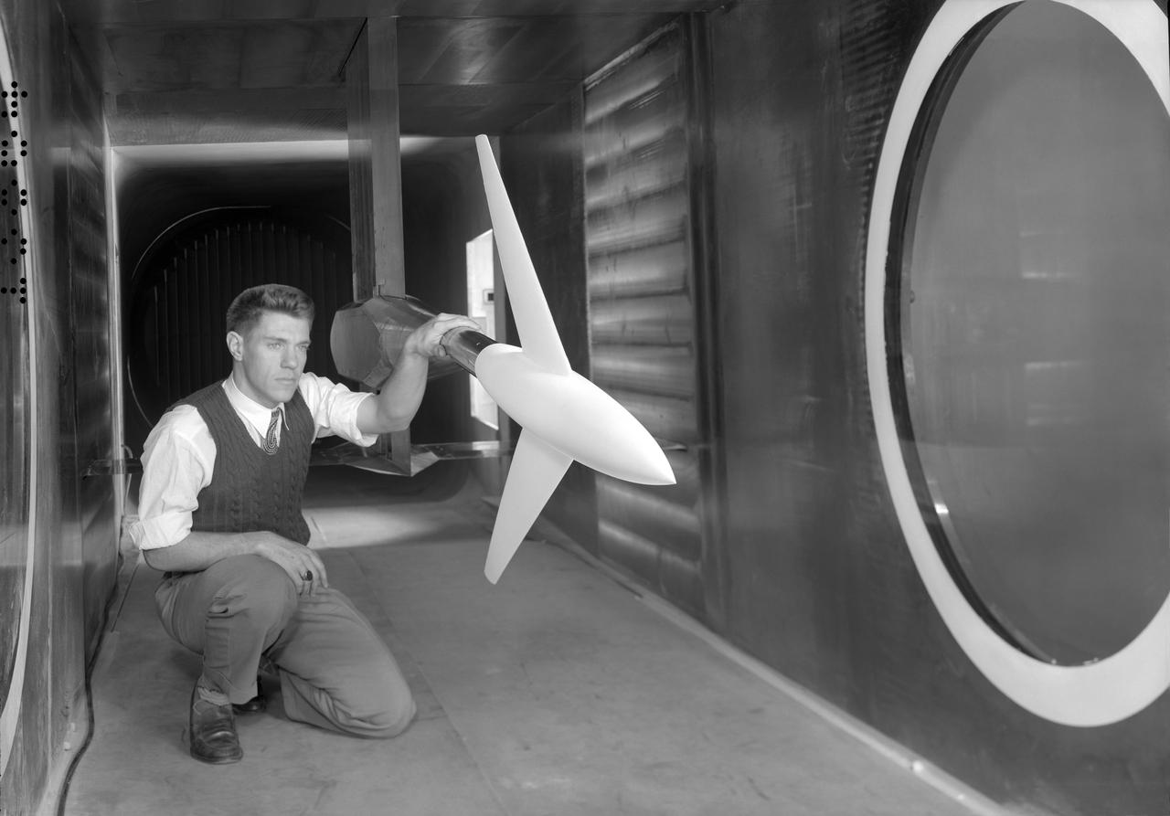
A chambered and twisted wing-body. Arrow wing hypersonic model tested in the 6x6 foot wind tunnel at the NASA Ames Research Center.
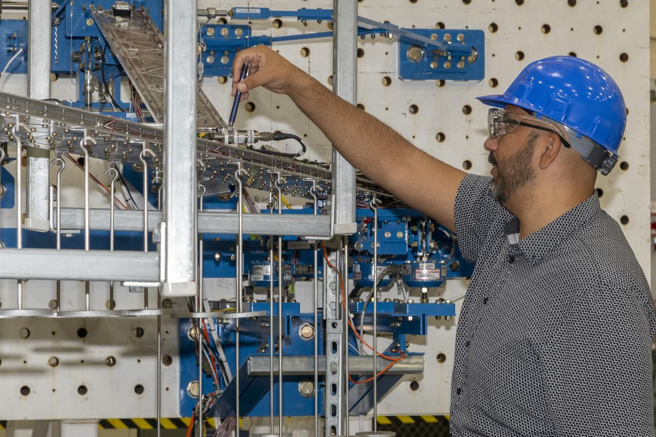
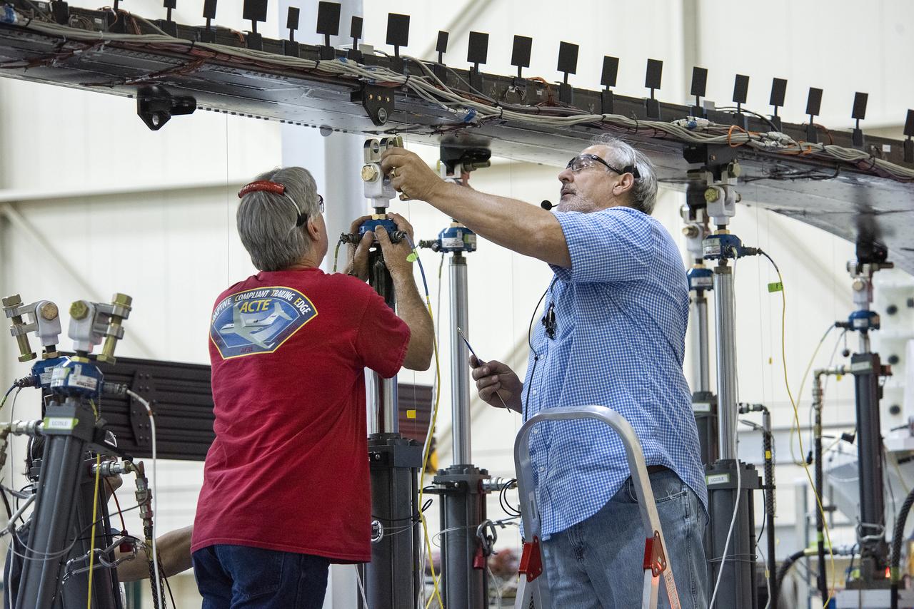
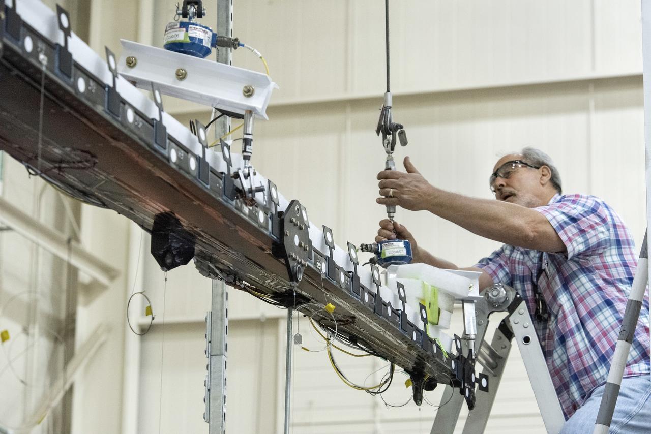
Researchers test a 10-foot Mock Truss-Braced Wing at NASA’s Armstrong Flight Research Center in Edwards, California. Frank Pena, test director, checks the mock wing. The aircraft concept involves a wing braced on an aircraft using diagonal struts that also add lift and could result in significantly improved aerodynamics.
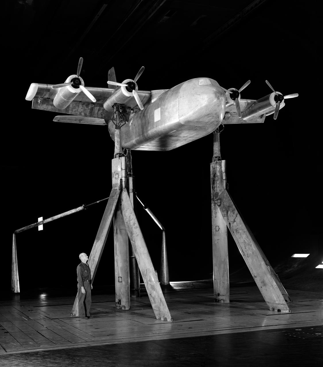
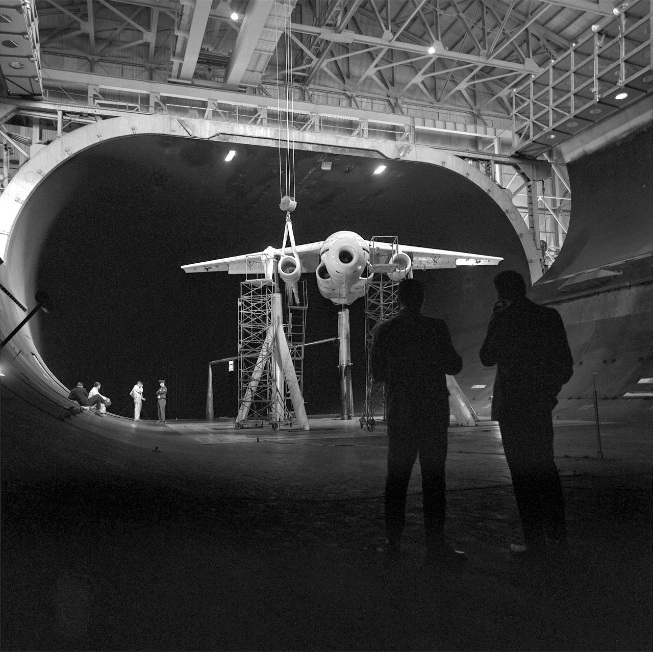
Investigation of a tilt-wing/propeller model with blowing flaps. 3/4 front view, tilt wing model, wing position = 0deg. C-123 fuselage, conventional struts, 4 props
3/4 front view from below of Delta wing Model with Nose Inlet in Ames 40x80 foot wind tunnel.
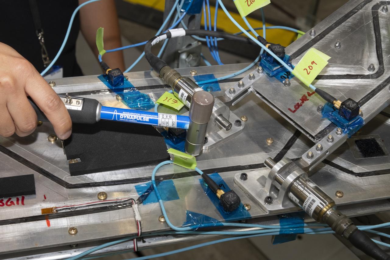
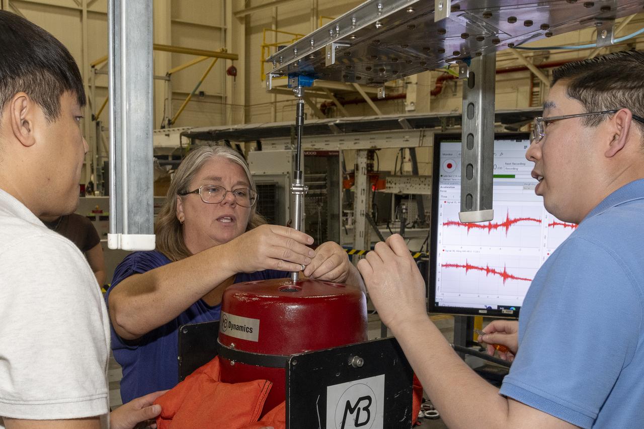
Researchers test a 10-foot Mock Truss-Braced Wing at NASA’s Armstrong Flight Research Center in Edwards, California. Ben Park, NASA mock wing ground vibration test director, taps the wing structure with an instrumented hammer in key locations and sensors monitor the results. The aircraft concept involves a wing braced on an aircraft using diagonal struts that also add lift and could result in significantly improved aerodynamics.
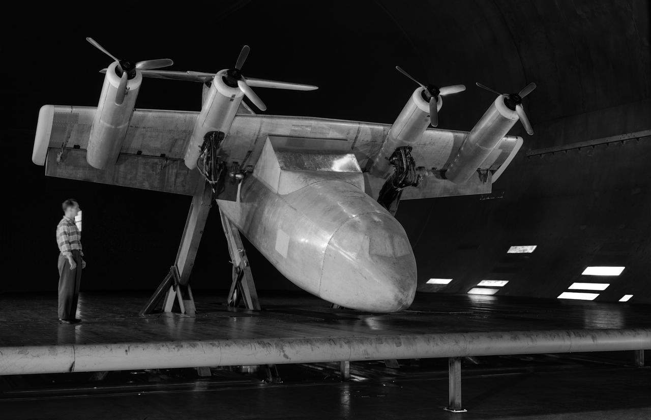
Tilt wing propeller model. 3/4 front view. 4 prop tilt wing nose down variable struts on ground board. Leo Holl, NASA Ames Engineer.
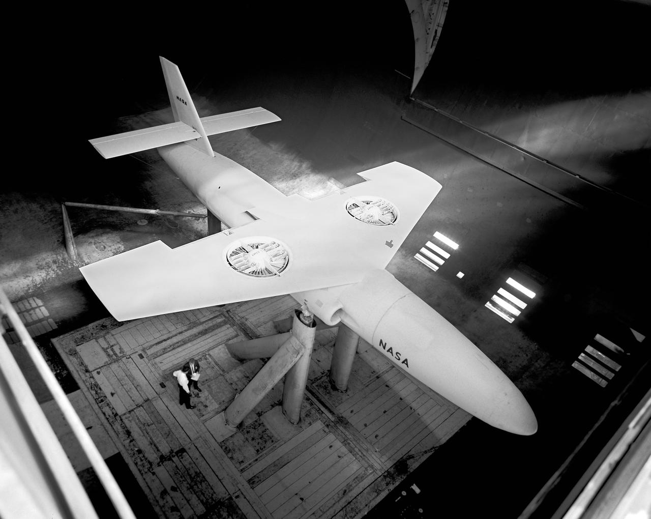
Top view if GE fan model, 3/4 top view. Straight wing. 1 fan per wing, conventional struts. Woody Kook, Branch Chief.
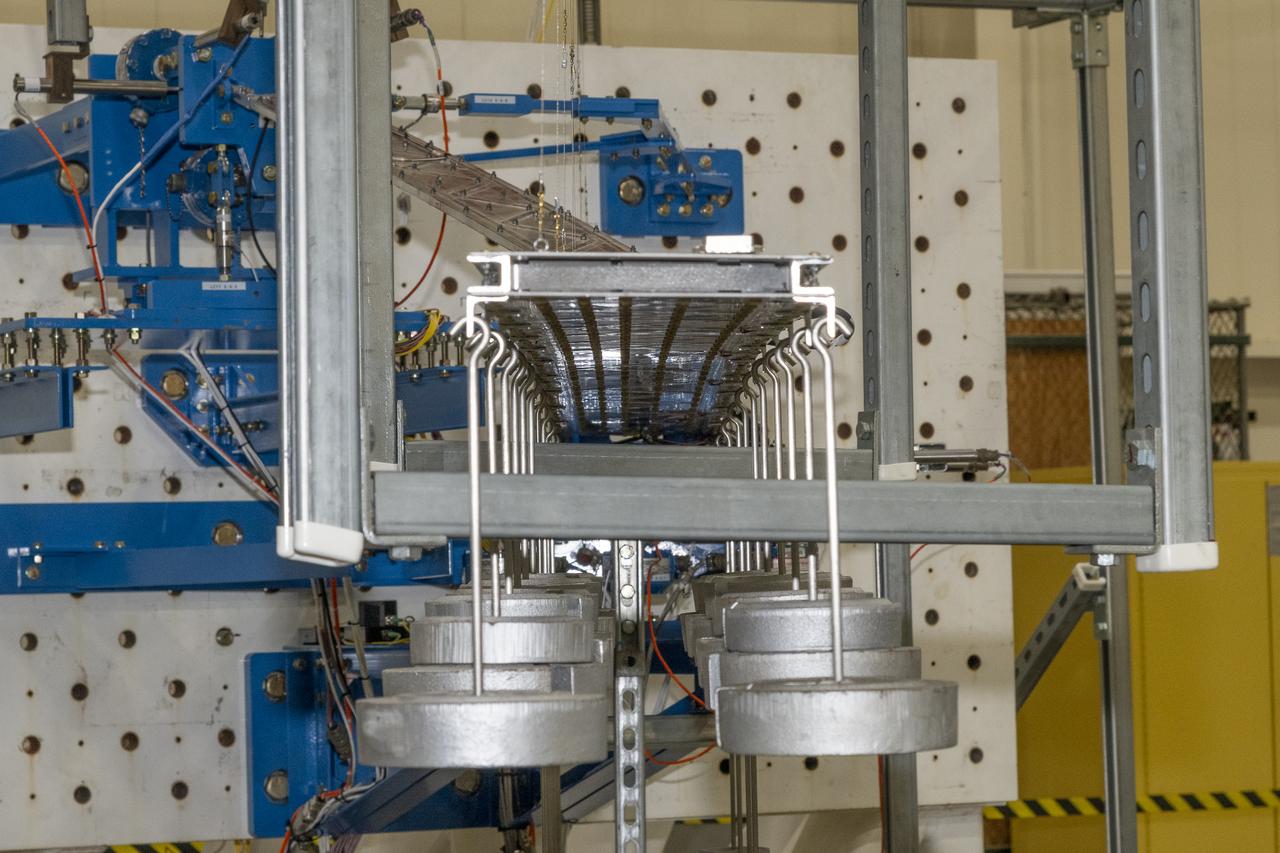
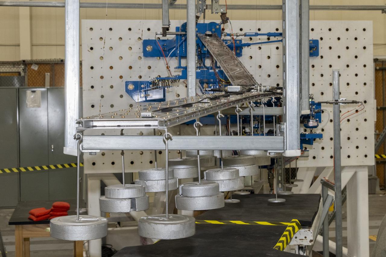
Researchers test a 10-foot Mock Truss-Braced Wing at NASA’s Armstrong Flight Research Center in Edwards, California. Weights are hung from the wing to apply stress used to determine its limits. The aircraft concept involves a wing braced on an aircraft using diagonal struts that also add lift and could result in significantly improved aerodynamics.
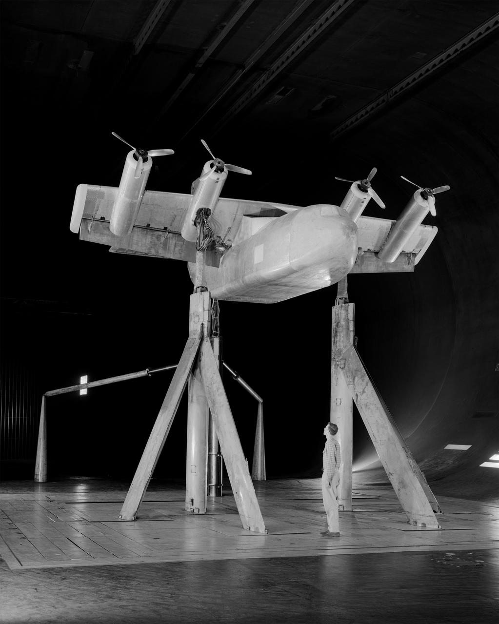
4 propeller Tilt Wing. Pictured with Tommy Wills wind tunnel mechanic in the 40x80 foot wind tunnel.
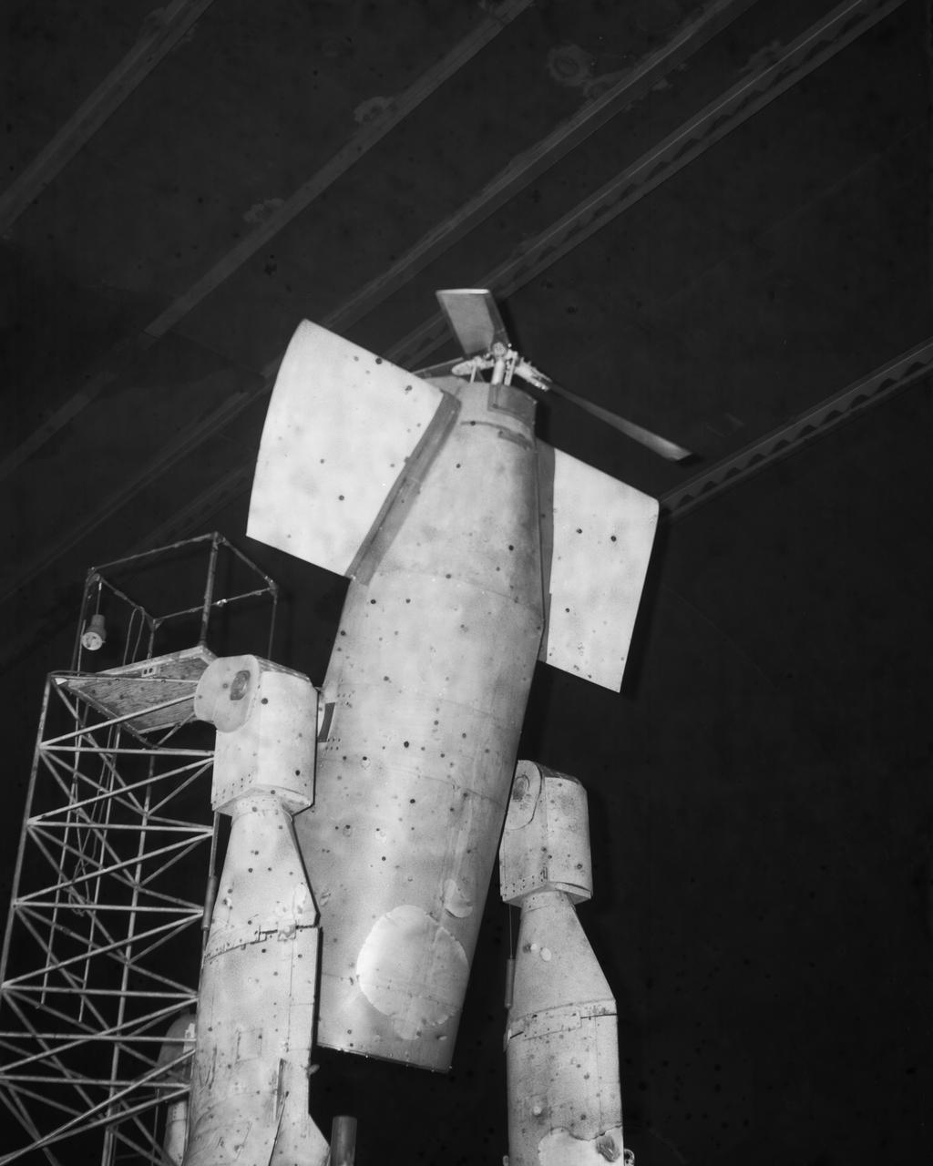
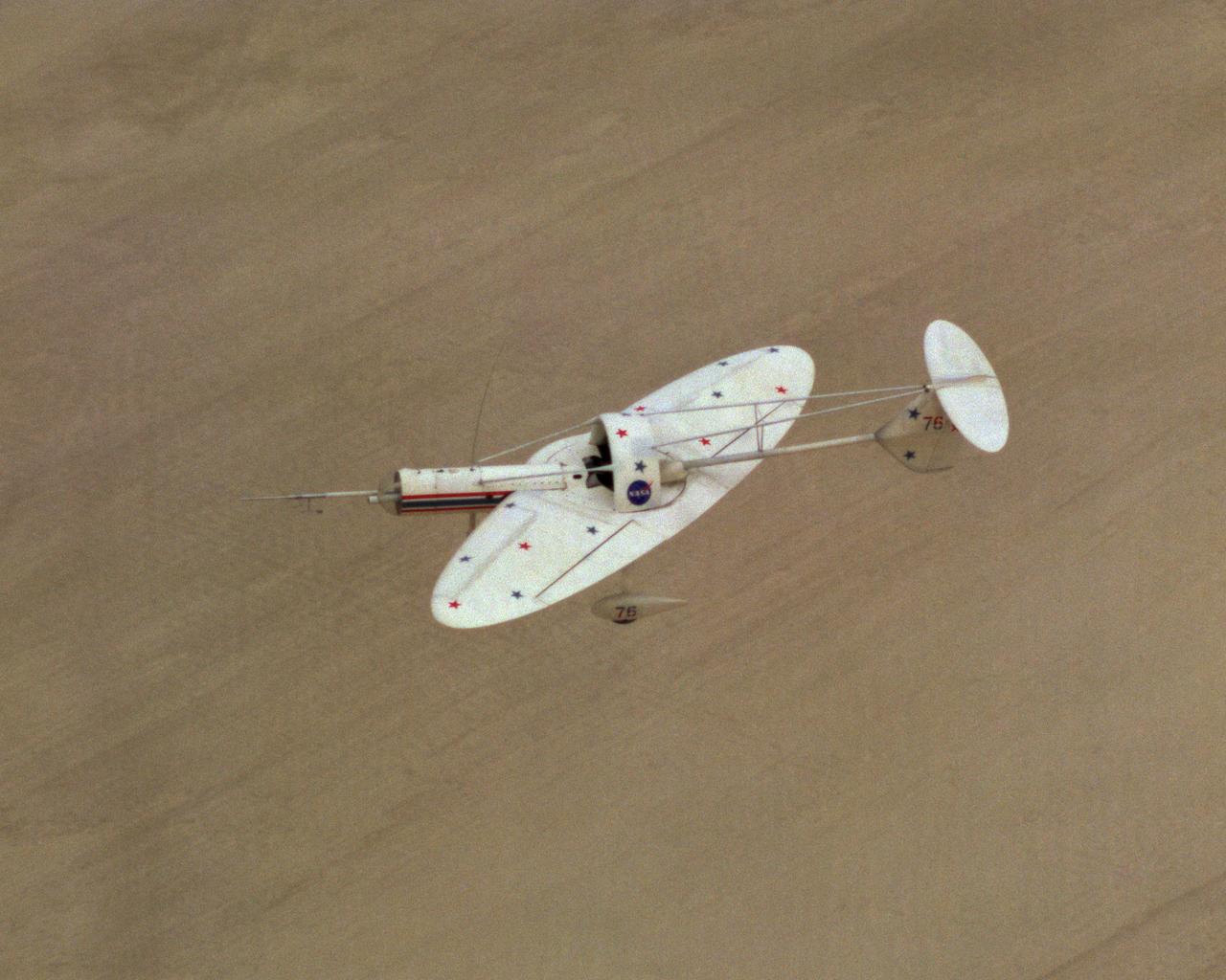
Vertol-76 Descent Test. Tilt Wing airplane prop rig at 80 deg. Angle of attack, in the 40x80 foot wind tunnel at NASA's Ames Research Center.
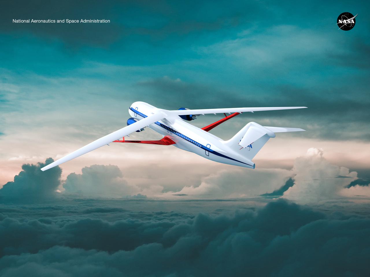
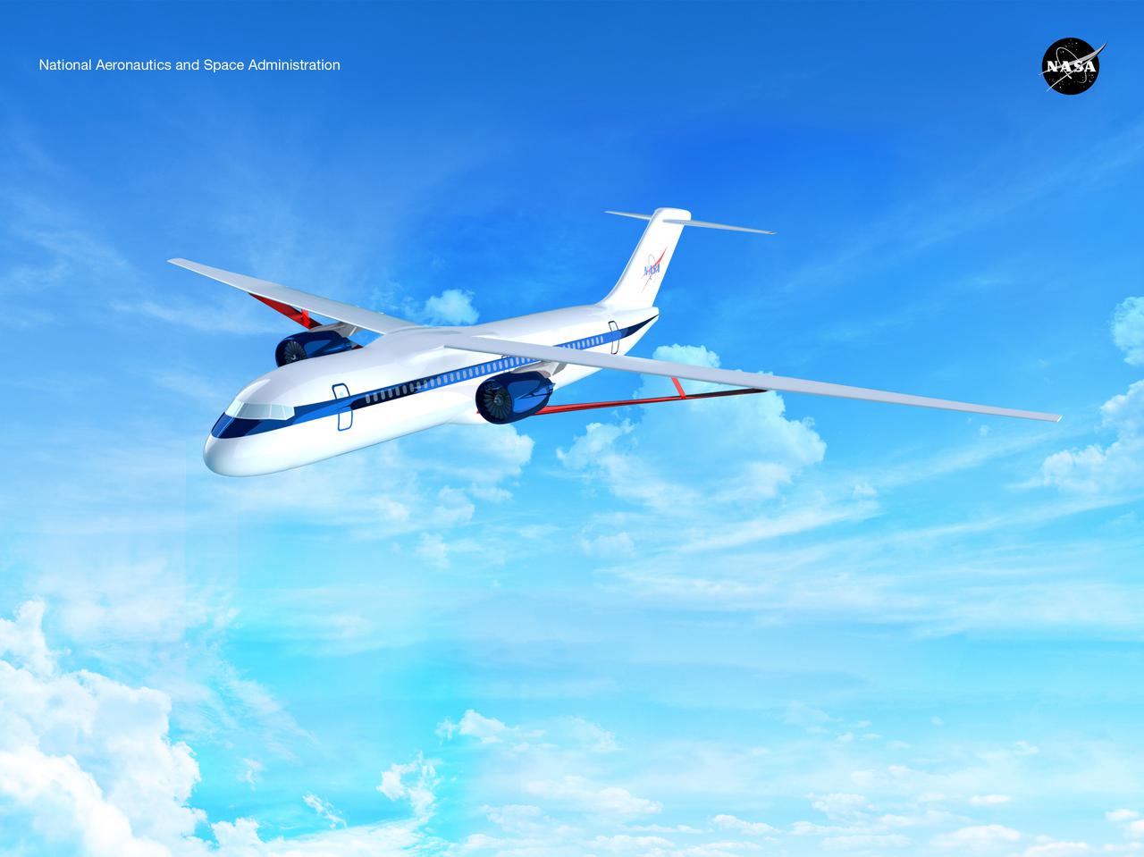
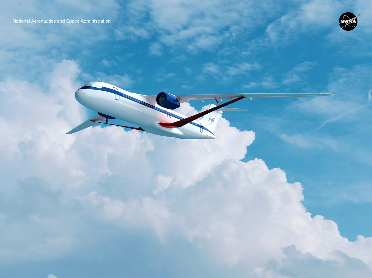
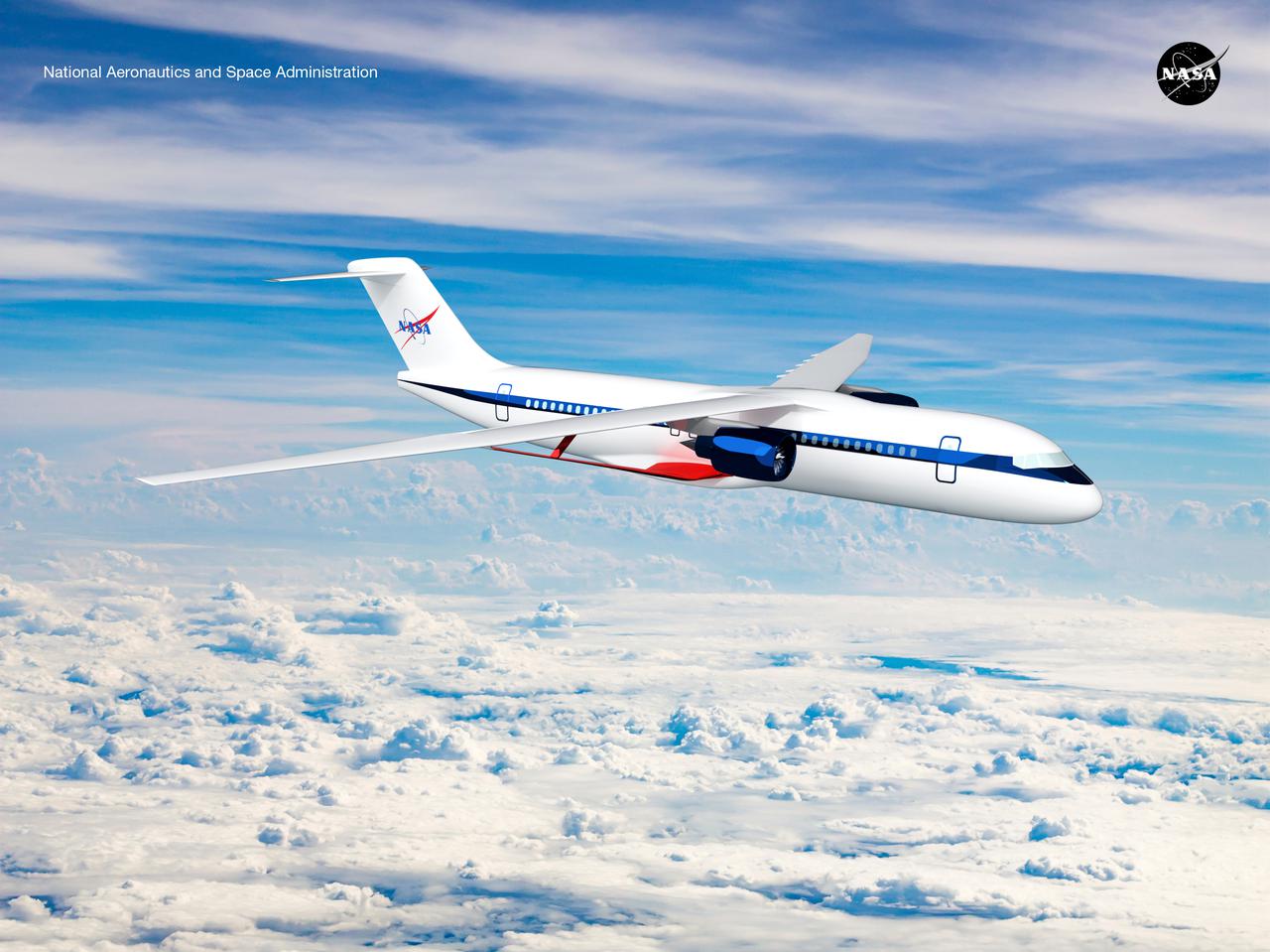
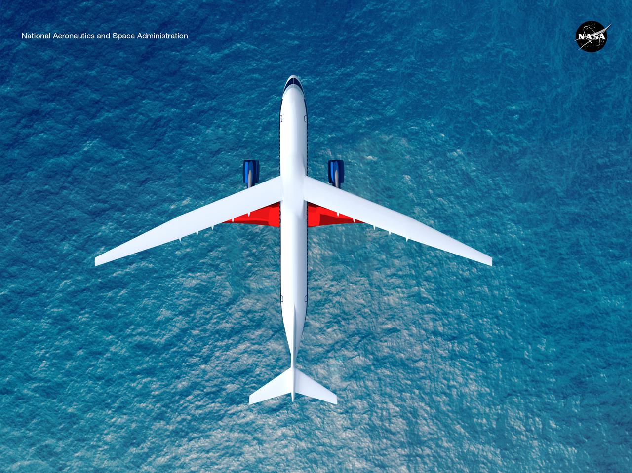
Notice anything different about the wings on this airliner? This conceptual truss-braced wing narrowbody is an aircraft with a 170ft span folding wing. By utilizing trusses, the aircraft can have longer, thinner wings with greater aspect ratios. This, in turn, translates into less drag and 5-10% less fuel burned. The Transonic Truss-Braced Wing aircraft originated from a joint effort by NASA and Boeing to develop subsonic commercial transport concepts – meeting NASA-defined metrics in terms of reduced noise, emissions, and fuel consumption. The design is currently undergoing wind tunnel testing and other studies by NASA researchers.
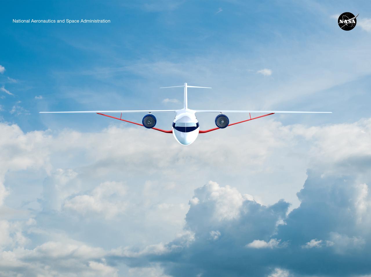
Notice anything different about the wings on this airliner? This conceptual truss-braced wing narrowbody is an aircraft with a 170ft span folding wing. By utilizing trusses, the aircraft can have longer, thinner wings with greater aspect ratios. This, in turn, translates into less drag and 5-10% less fuel burned. The Transonic Truss-Braced Wing aircraft originated from a joint effort by NASA and Boeing to develop subsonic commercial transport concepts – meeting NASA-defined metrics in terms of reduced noise, emissions, and fuel consumption. The design is currently undergoing wind tunnel testing and other studies by NASA researchers.
Researchers test a 10-foot Mock Truss-Braced Wing at NASA’s Armstrong Flight Research Center in Edwards, California. The aircraft concept involves a wing braced on an aircraft using diagonal struts that also add lift and could result in significantly improved aerodynamics.
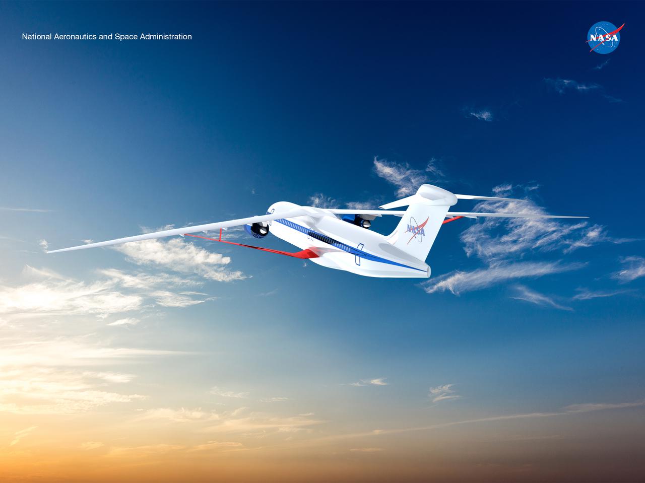
Notice anything different about the wings on this airliner? This conceptual truss-braced wing narrowbody is an aircraft with a 170ft span folding wing. By utilizing trusses, the aircraft can have longer, thinner wings with greater aspect ratios. This, in turn, translates into less drag and 5-10% less fuel burned. The Transonic Truss-Braced Wing aircraft originated from a joint effort by NASA and Boeing to develop subsonic commercial transport concepts – meeting NASA-defined metrics in terms of reduced noise, emissions, and fuel consumption. The design is currently undergoing wind tunnel testing and other studies by NASA researchers.
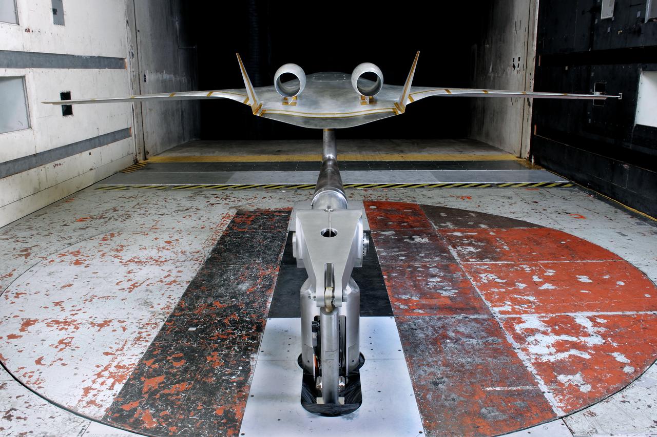
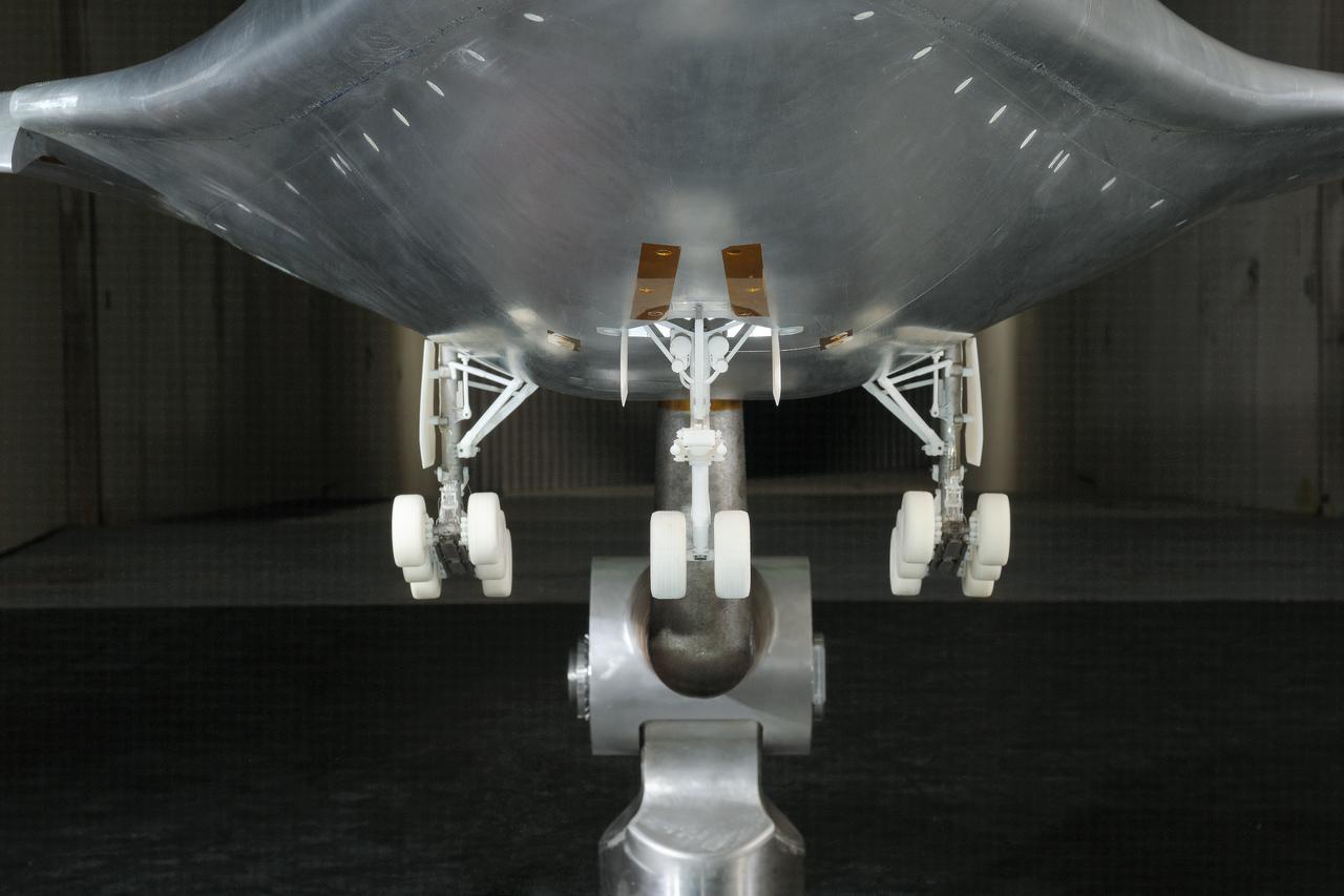
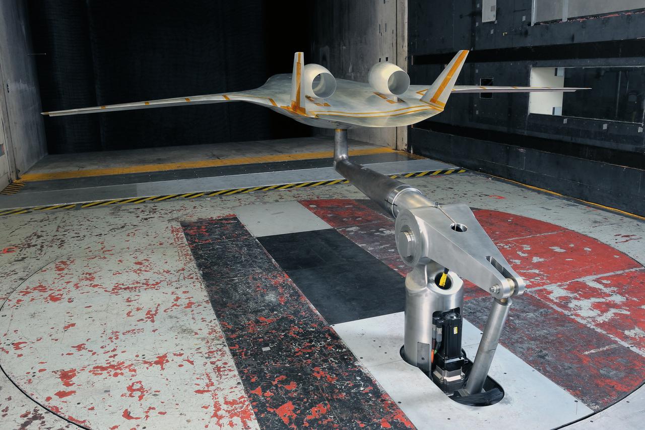
(HWB) Hybrid Wing Body Aerodynamic Test in 14x22 12.3 Foot Span HWB Model as tested in the 14x22 Foot Subsonic Tennel Aerodynamic Test
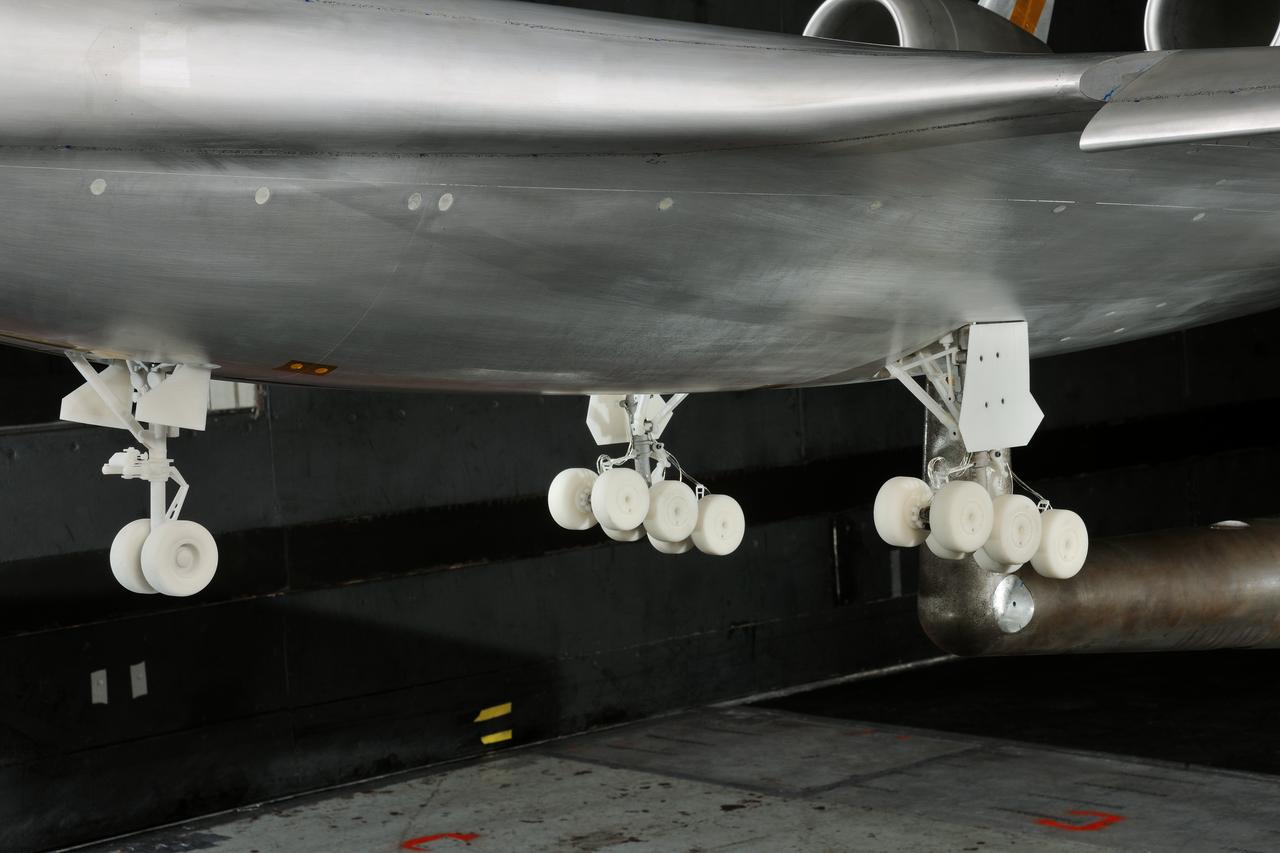
(HWB) Hybrid Wing Body Aerodynamic Test in 14x22 12.3 Foot Span HWB Model as tested in the 14x22 Foot Subsonic Tennel Aerodynamic Test
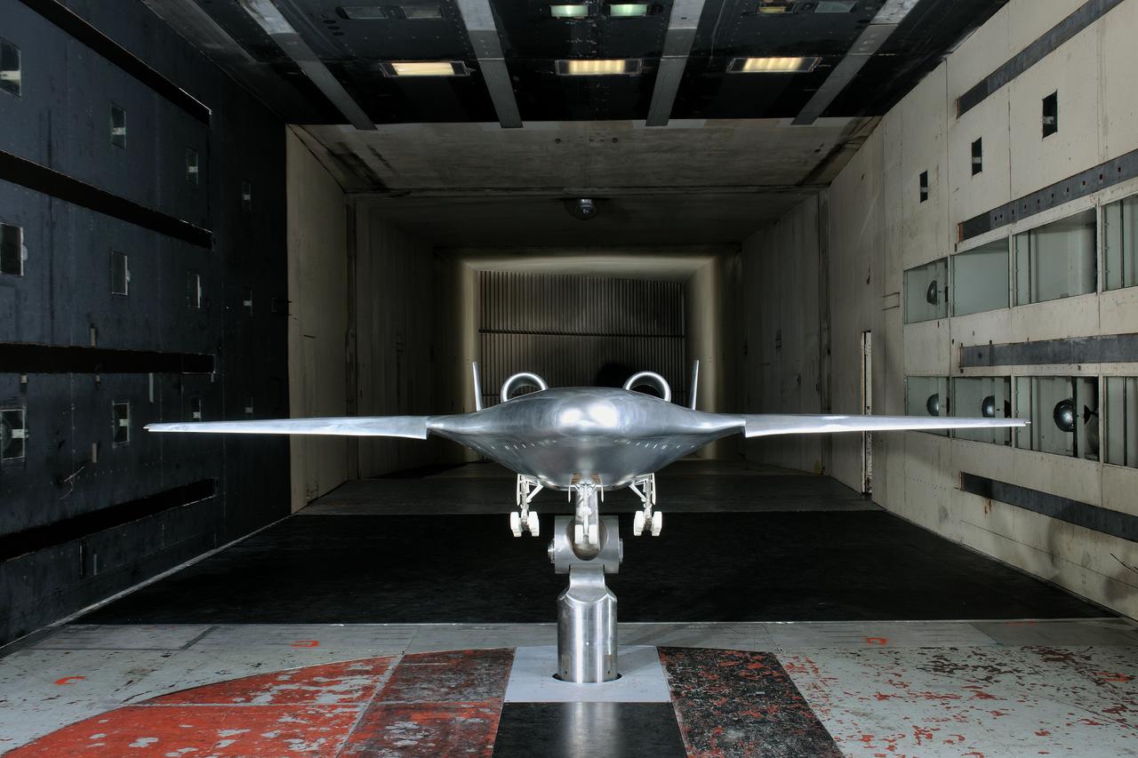
(HWB) Hybrid Wing Body Aerodynamic Test in 14x22 12.3 Foot Span HWB Model as tested in the 14x22 Foot Subsonic Tennel Aerodynamic Test
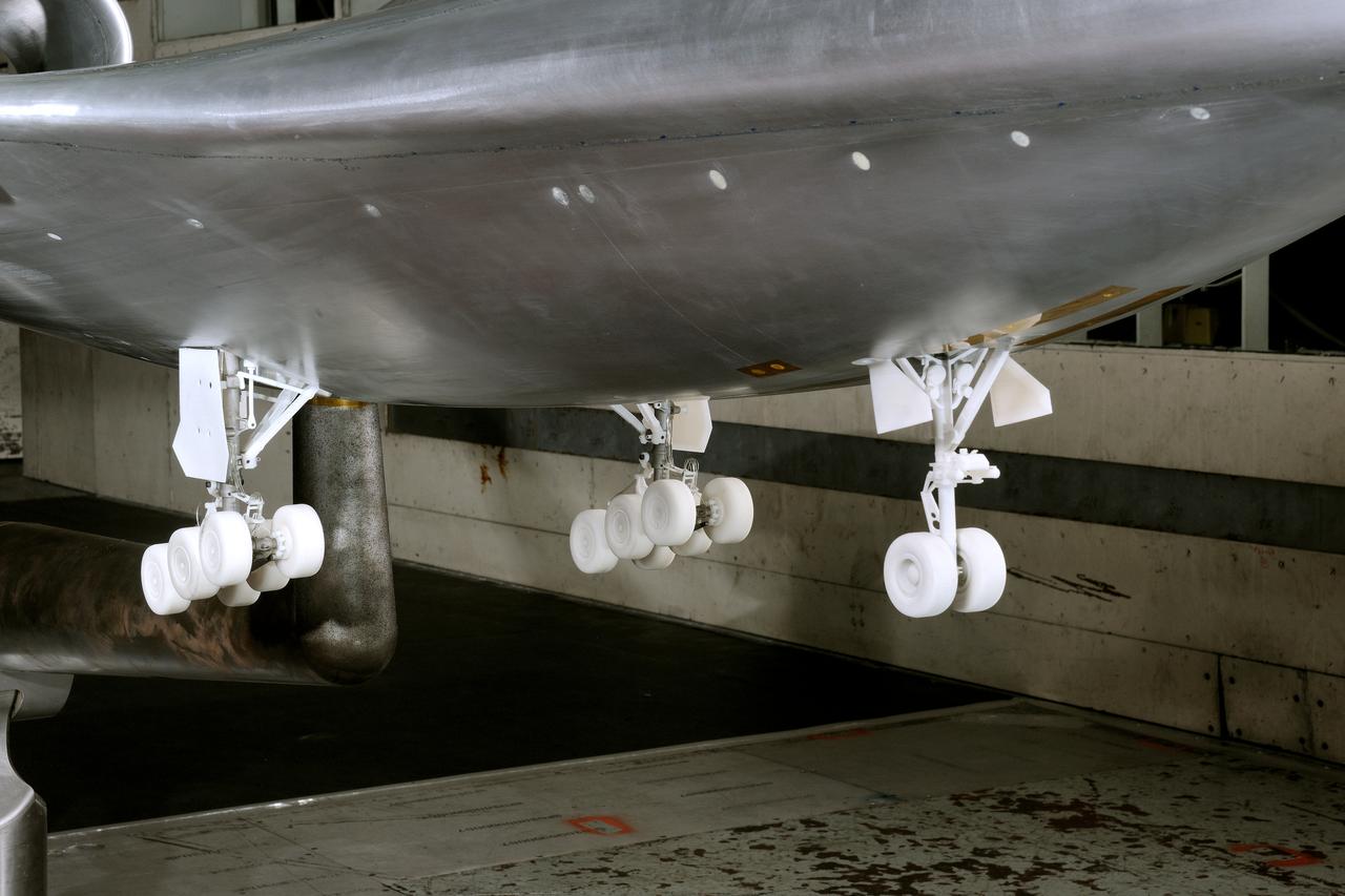
(HWB) Hybrid Wing Body Aerodynamic Test in 14x22 12.3 Foot Span HWB Model as tested in the 14x22 Foot Subsonic Tennel Aerodynamic Test
(HWB) Hybrid Wing Body Aerodynamic Test in 14x22 12.3 Foot Span HWB Model as tested in the 14x22 Foot Subsonic Tennel Aerodynamic Test
(HWB) Hybrid Wing Body Aerodynamic Test in 14x22 12.3 Foot Span HWB Model as tested in the 14x22 Foot Subsonic Tennel Aerodynamic Test
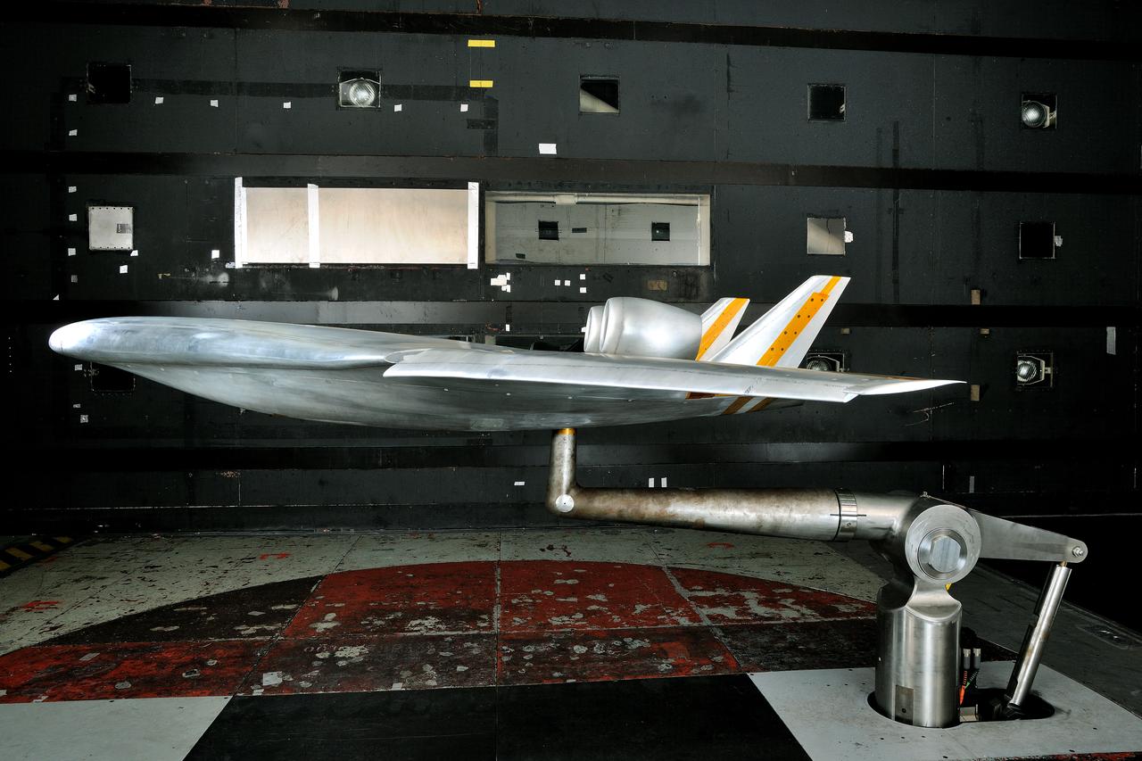
(HWB) Hybrid Wing Body Aerodynamic Test in 14x22 12.3 Foot Span HWB Model as tested in the 14x22 Foot Subsonic Tennel Aerodynamic Test
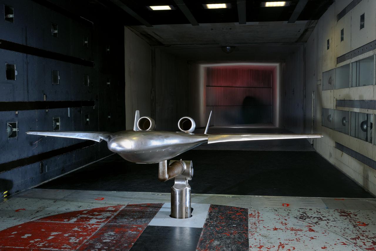
(HWB) Hybrid Wing Body Aerodynamic Test in 14x22 12.3 Foot Span HWB Model as tested in the 14x22 Foot Subsonic Tennel Aerodynamic Test
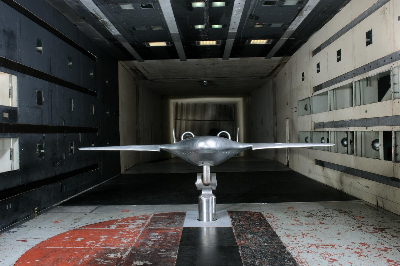
(HWB) Hybrid Wing Body Aerodynamic Test in 14x22 12.3 Foot Span HWB Model as tested in the 14x22 Foot Subsonic Tennel Aerodynamic Test

(HWB) Hybrid Wing Body Aerodynamic Test in 14x22 12.3 Foot Span HWB Model as tested in the 14x22 Foot Subsonic Tennel Aerodynamic Test
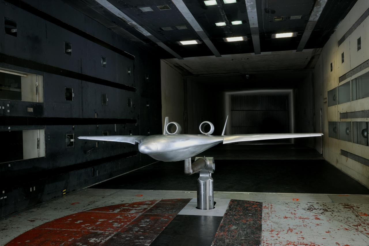
(HWB) Hybrid Wing Body Aerodynamic Test in 14x22 12.3 Foot Span HWB Model as tested in the 14x22 Foot Subsonic Tennel Aerodynamic Test
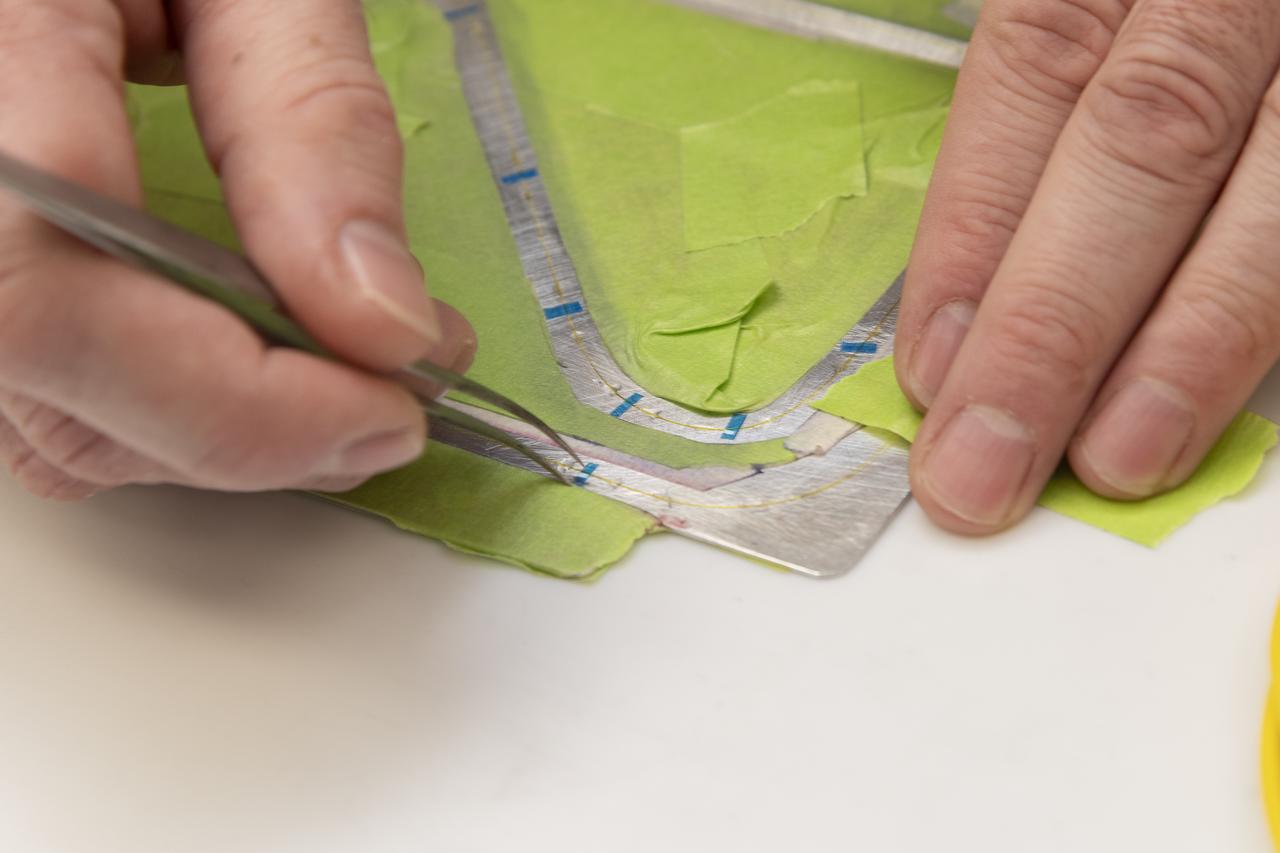
Engineering technician Jeff Howell removes tape from the Mock Truss-Braced Wing 10-foot model at NASA’s Armstrong Flight Research Center in Edwards, California. The tape was used to limit the amount of epoxy on the model wing during the process to secure the fiber optic strain sensors to the wing.
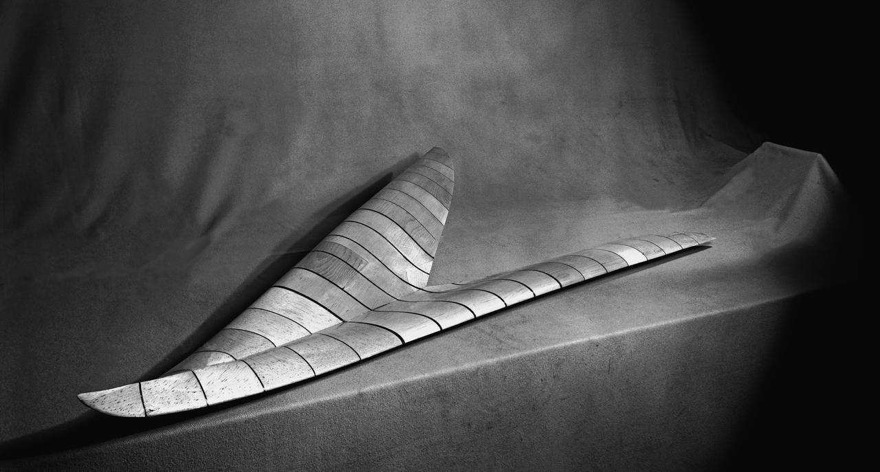
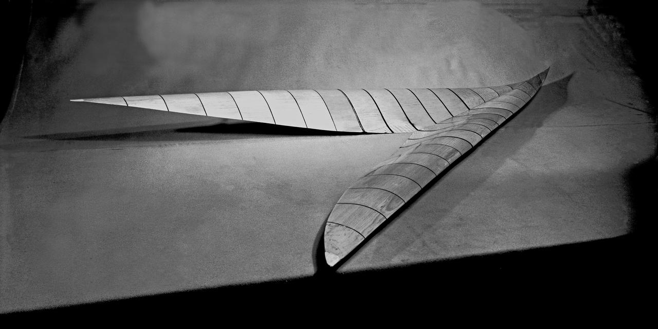
Wood Mock-up of Arrow Wing Bomber to Show Wing Contours

Wood Mock-up of Arrow- Wing Bomber to Show Wing Contours

Wood Mock-up of Arrow- Wing Bomber to Show Wing Contours
Wood Mock-up of Arrow- Wing Bomber to Show Wing Contours
Front View of -45 deg. Forward swept wing with inboard split flaps deflected 60 deg. In NACA Ames 40x80 foot Wind Tunnel.

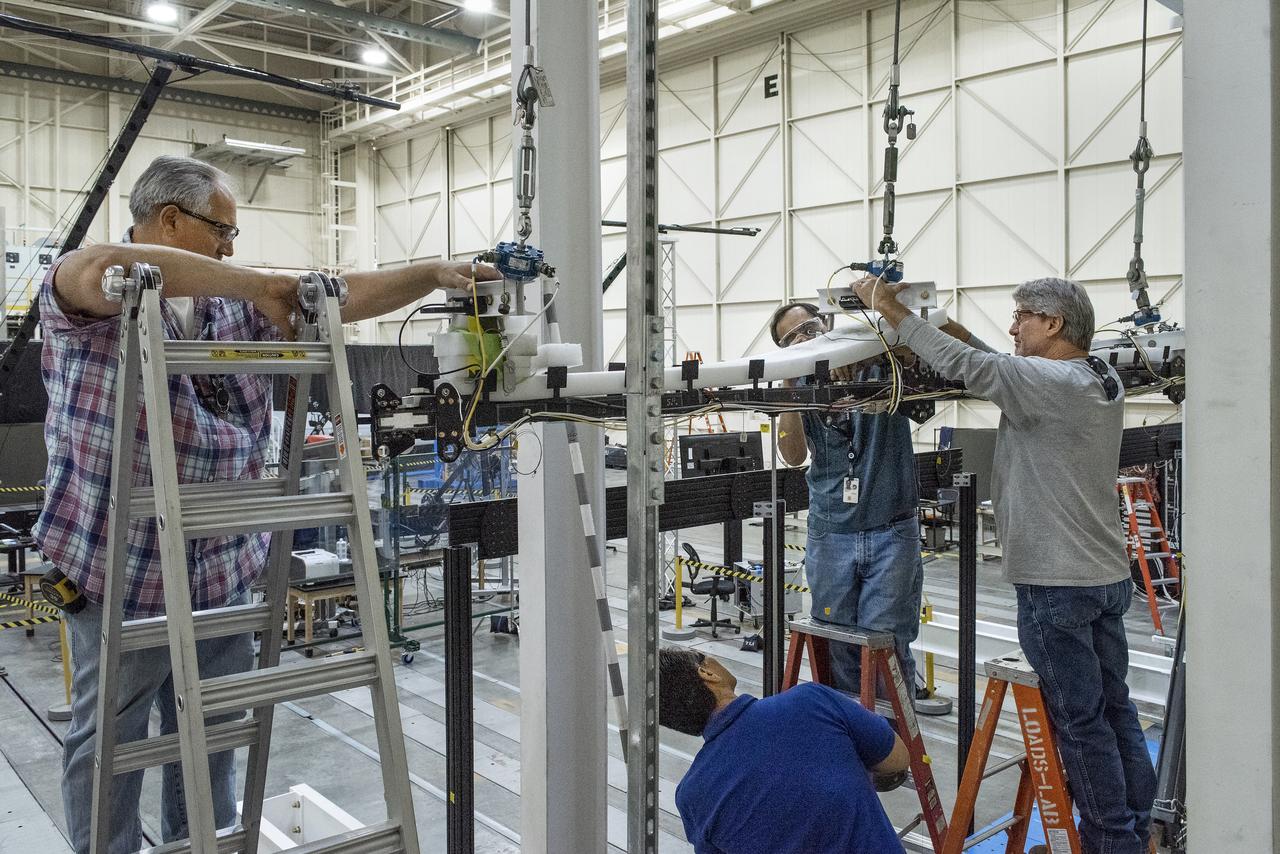
Researchers test a 10-foot Mock Truss-Braced Wing at NASA’s Armstrong Flight Research Center in Edwards, California. From left, test director Frank Pena and Ray Sadler watch as Lucas Oramas, left, and Charlie Eloff add weight to the test wing to apply stress used to determine its limits. The aircraft concept involves a wing braced on an aircraft using diagonal struts that also add lift and could result in significantly improved aerodynamics.
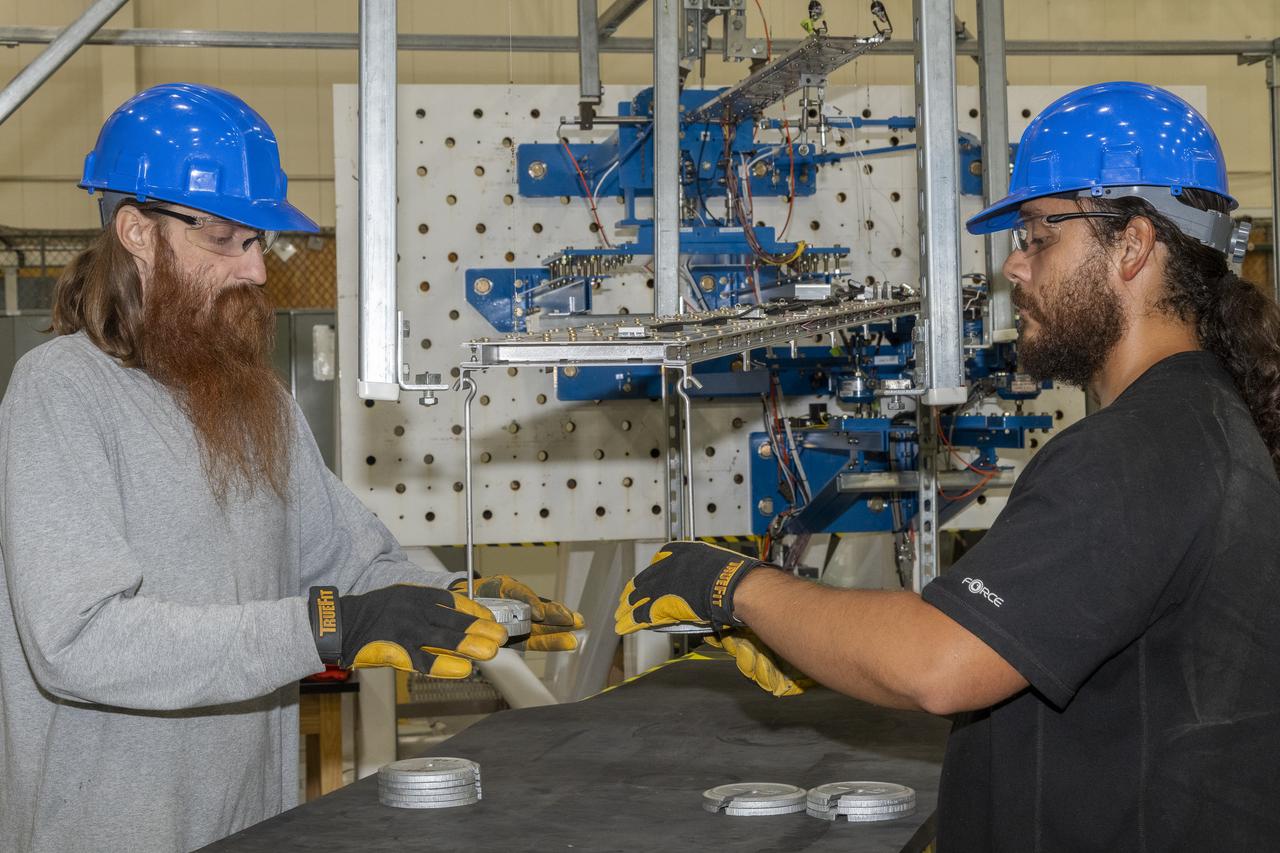
Researchers test a 10-foot Mock Truss-Braced Wing at NASA’s Armstrong Flight Research Center in Edwards, California. Charlie Eloff, left, and Lucas Oramas add weight to the test wing to apply stress used to determine its limits. The aircraft concept involves a wing braced on an aircraft using diagonal struts that also add lift and could result in significantly improved aerodynamics.
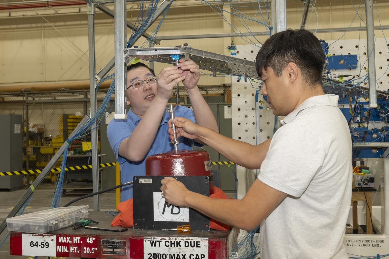
Researchers test a 10-foot Mock Truss-Braced Wing at NASA’s Armstrong Flight Research Center in Edwards, California. Samson Truong, from left, and Ben Park, NASA mock wing ground vibration test director, prepare for a vibration test. The aircraft concept involves a wing braced on an aircraft using diagonal struts that also add lift and could result in significantly improved aerodynamics.
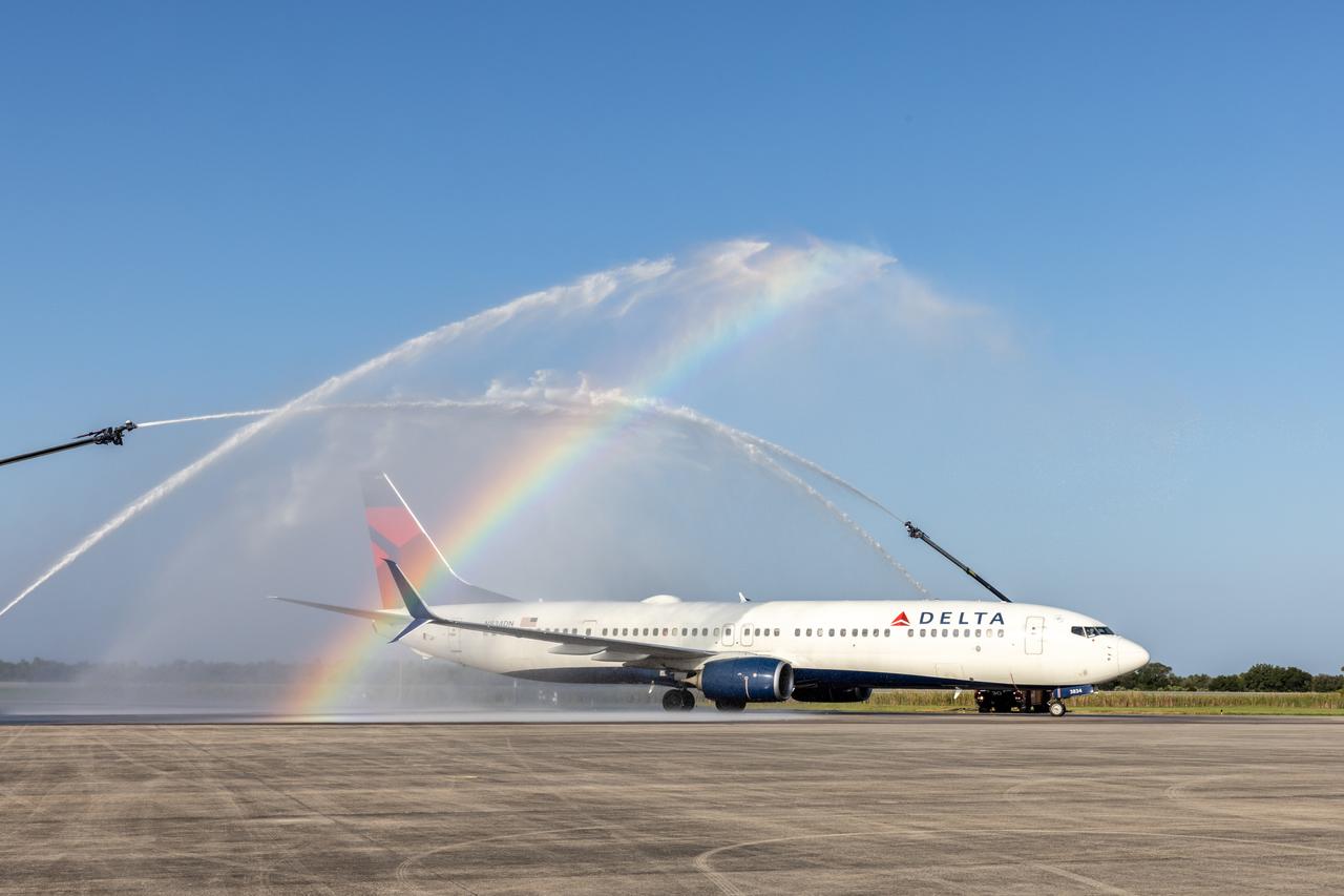
A Delta plane, carrying an all-female crew and 130 young women ages 11 to 18, received a “water salute” upon arrival on Friday, Sept. 20, 2024, at the Launch and Landing Facility at NASA’s Kennedy Space Center in Florida. Part of the Delta Air Lines’ Women Inspiring Our Next Generation (WING) flight, the young women from the Atlanta, Georgia area, learned about the various women-led STEM (science, technology, engineering, and math) careers available at the Florida spaceport.
Young women, ages 11 to 18, from the Atlanta, Georgia area, with interests in STEM (science, technology, engineering, and math), pose for a photo on Friday, Sept. 20, 2024, at NASA’s Kennedy Space Center in Florida. NASA Kennedy hosted the Delta Air Lines’ Women Inspiring Our Next Generation (WING) flight to showcase various women-led STEM careers available at the Florida spaceport.
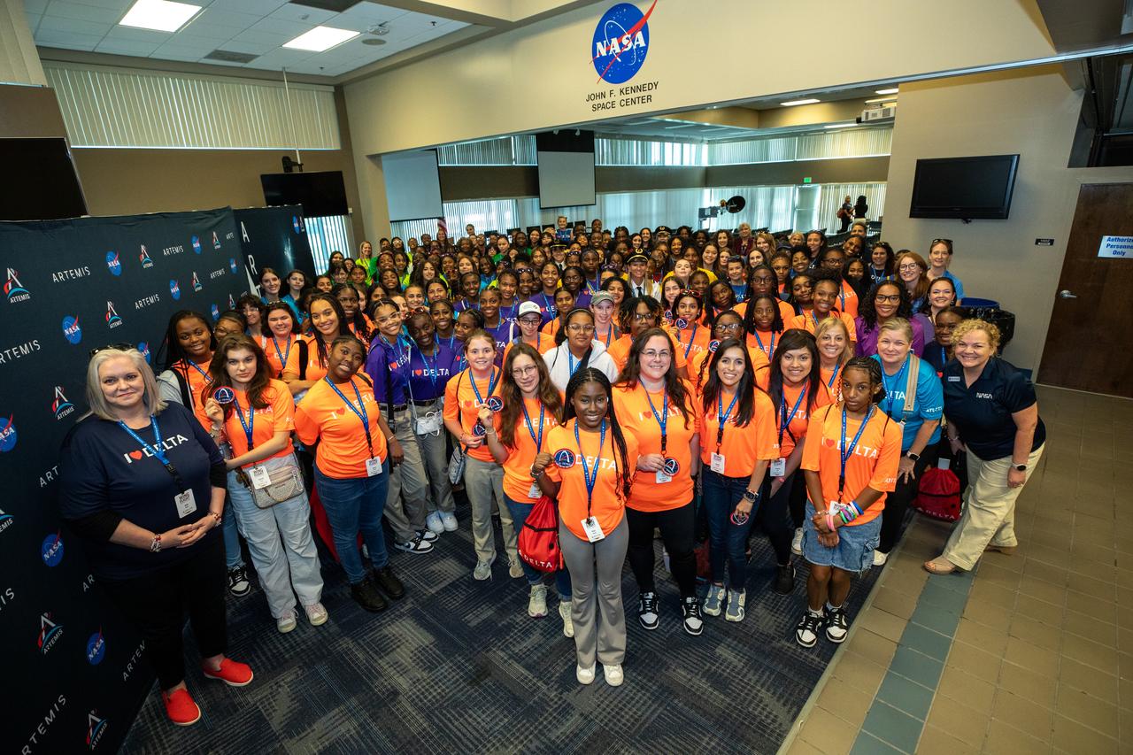
Young women, ages 11 to 18, from the Atlanta, Georgia area, with interests in STEM (science, technology, engineering, and math), pose for a photo on Friday, Sept. 20, 2024, at NASA’s Kennedy Space Center in Florida. NASA Kennedy hosted the Delta Air Lines’ Women Inspiring Our Next Generation (WING) flight to showcase various women-led STEM careers available at the Florida spaceport.
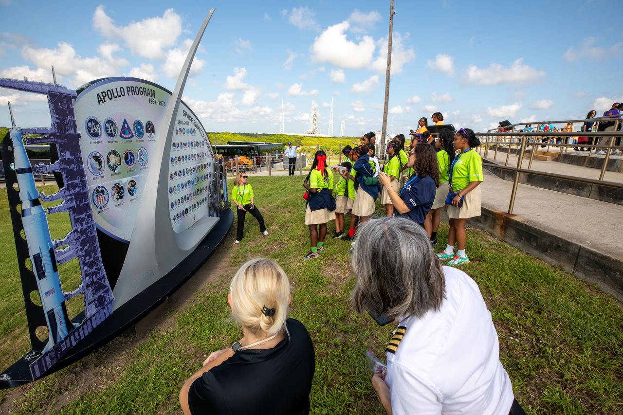
Young women, ages 11 to 18, visited launch pads 39A and 39B on Friday, Sept. 20, 2024, at the agency’s Kennedy Space Center in Florida. Part of the Delta Air Lines’ Women Inspiring Our Next Generation (WING) flight, the young women from the Atlanta, Georgia area, learned about the various women-led STEM (science, technology, engineering, and math) careers available at the Florida spaceport.
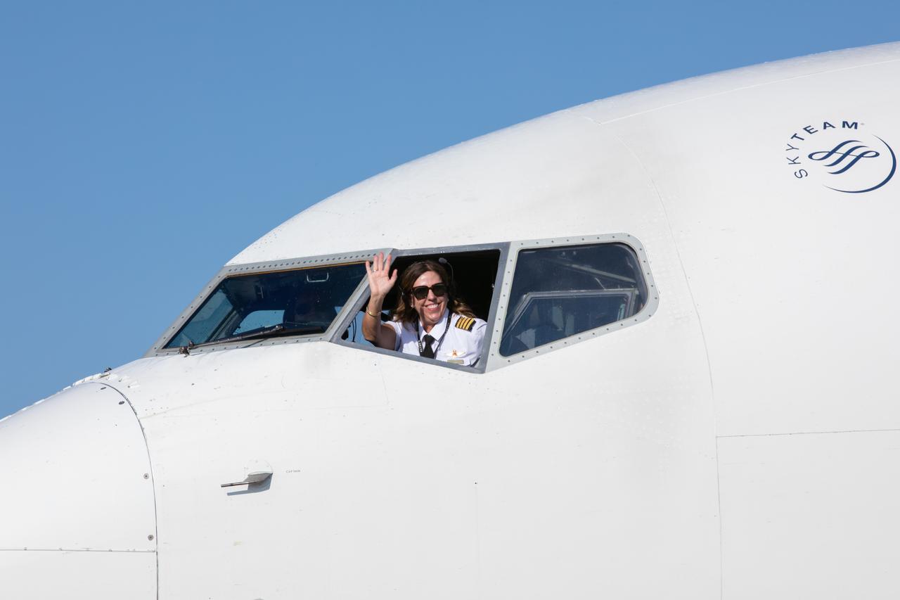
Part of the all-female crew for Delta Air Lines’ Women Inspiring Our Next Generation (WING) flight waves to a crowd on Friday, Sept. 20, 2024, after touching down at the Launch and Landing Facility at NASA’s Kennedy Space Center in Florida. The flight brought young ladies from Atlanta, Georgia, ranging in age from 11 to 18, to learn about the various women-led STEM (science, technology, engineering, and math) careers available at the Florida spaceport.
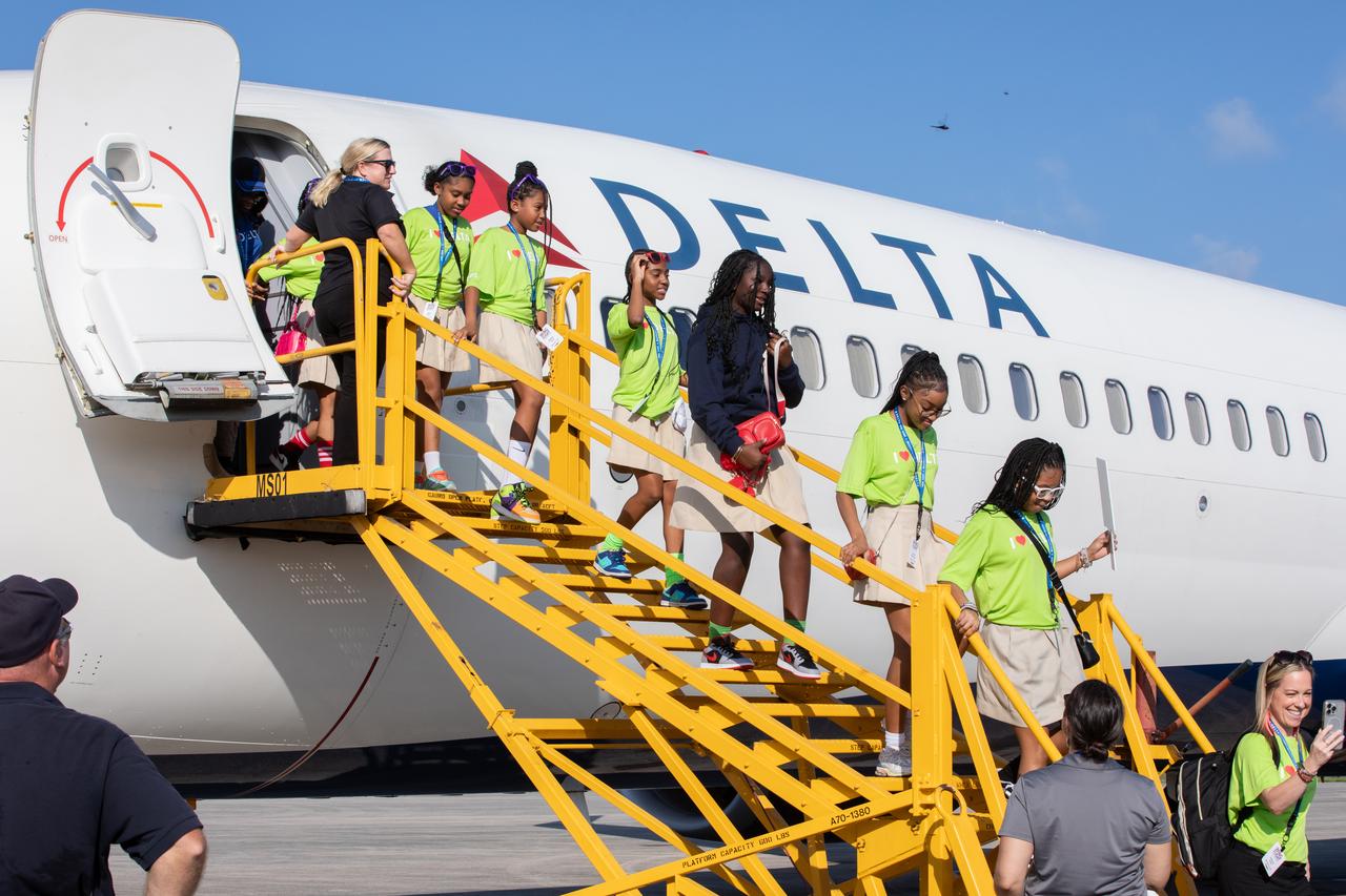
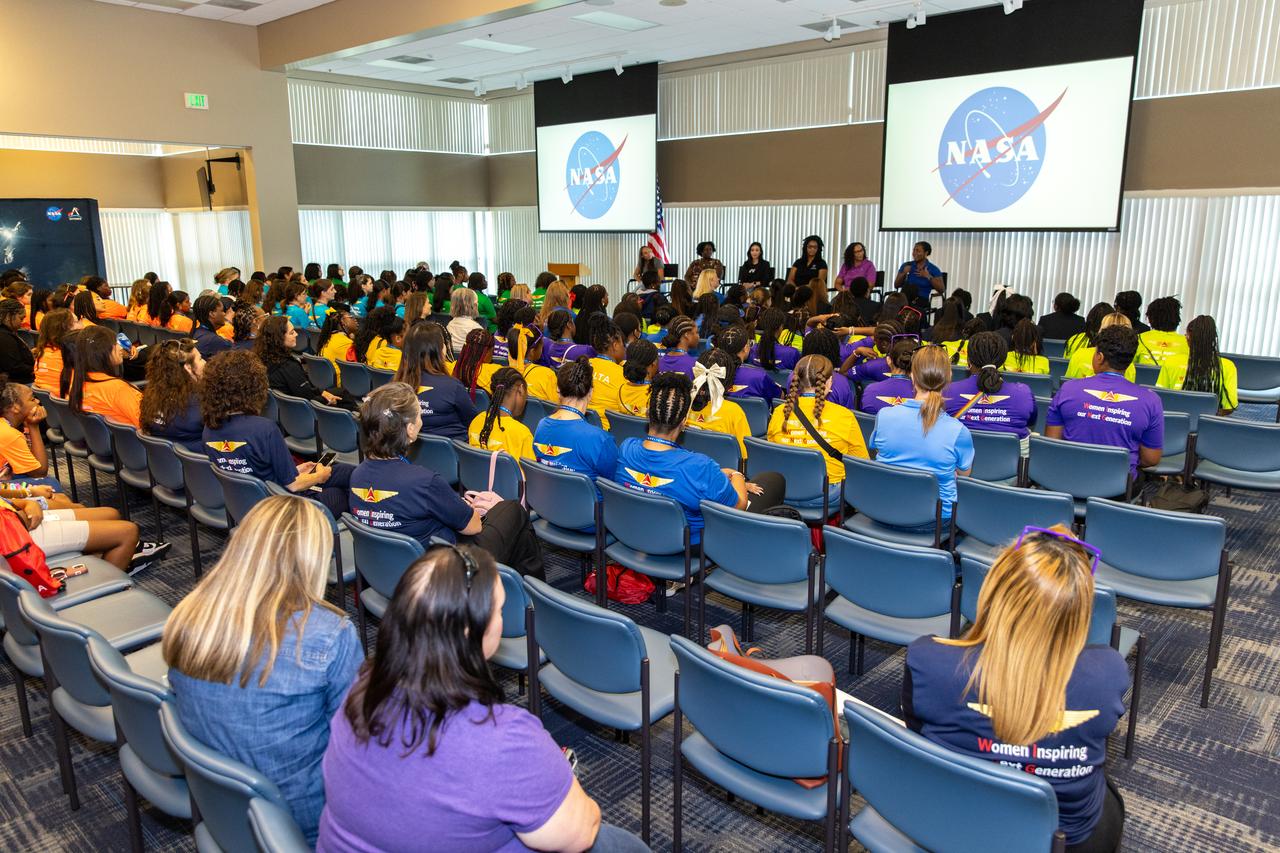
Roughly 130 young women with an interest in STEM (science, technology, engineering, and math) from Delta Air Lines’ Women Inspiring Our Next Generation (WING) flight arrive Friday, Sept. 20, 2024, at NASA’s Kennedy Space Center in Florida. The initiative between Delta and NASA Kennedy showcases the various STEM careers available at the Florida spaceport. The group had the opportunity to view center facilities and hear from a panel of women about their careers at Kennedy and Delta.
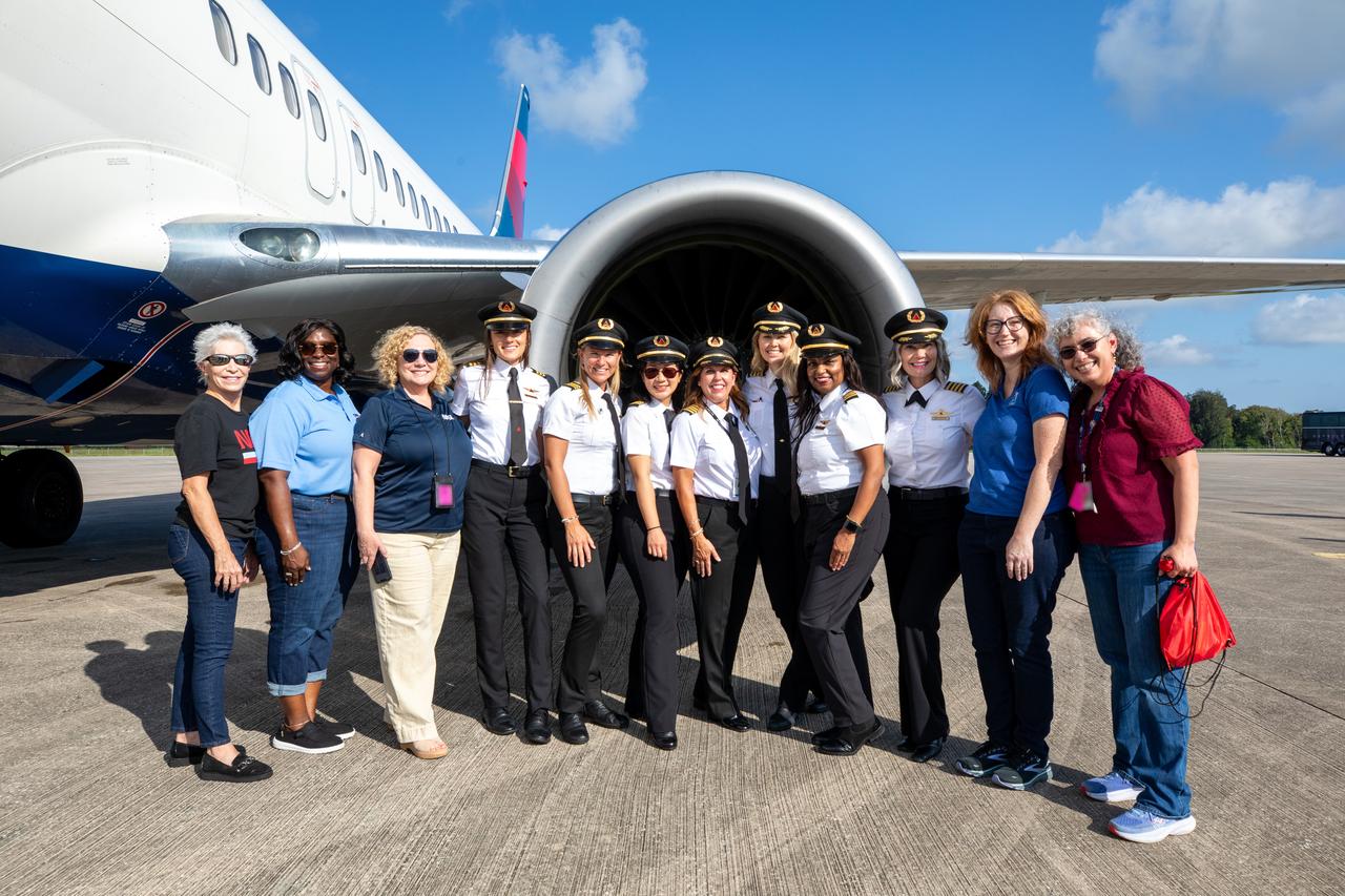
Women with leadership positions at NASA’s Kennedy Space Center pose with members of the all-female crew for Delta Air Lines’ Women Inspiring Our Next Generation (WING) flight after the crew touched down on Friday, Sept. 20, 2024, at the Launch and Landing Facility at the Florida spaceport. The flight brought girls from Atlanta, Georgia, ranging in age from 11 to 18, to view center facilities and hear a panel of women discuss their careers with NASA and Delta Air Lines.
(11/12/1971) 3/4 Scale swept augmentor wing Quest model being installed into the test section of the ames 40 x 80 foot wind tunnel, overhead doors open.
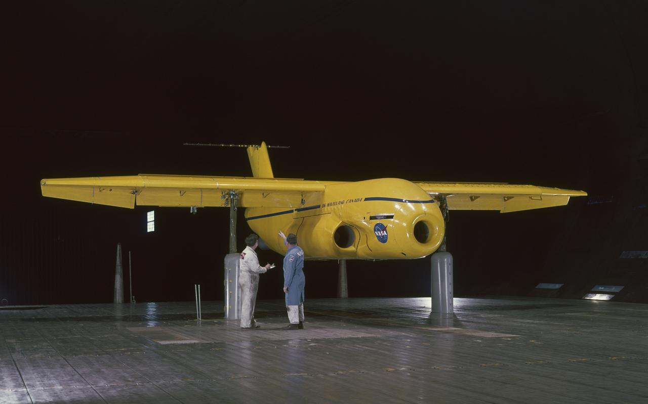
3/4 front view, a=0. de Havilland Augmenter Wing Model, High Lift System in Ames 40x80 Foot Wind Tunnel. Cecil McDonald and Al Wheelband in picture.
Wings Over Columbus
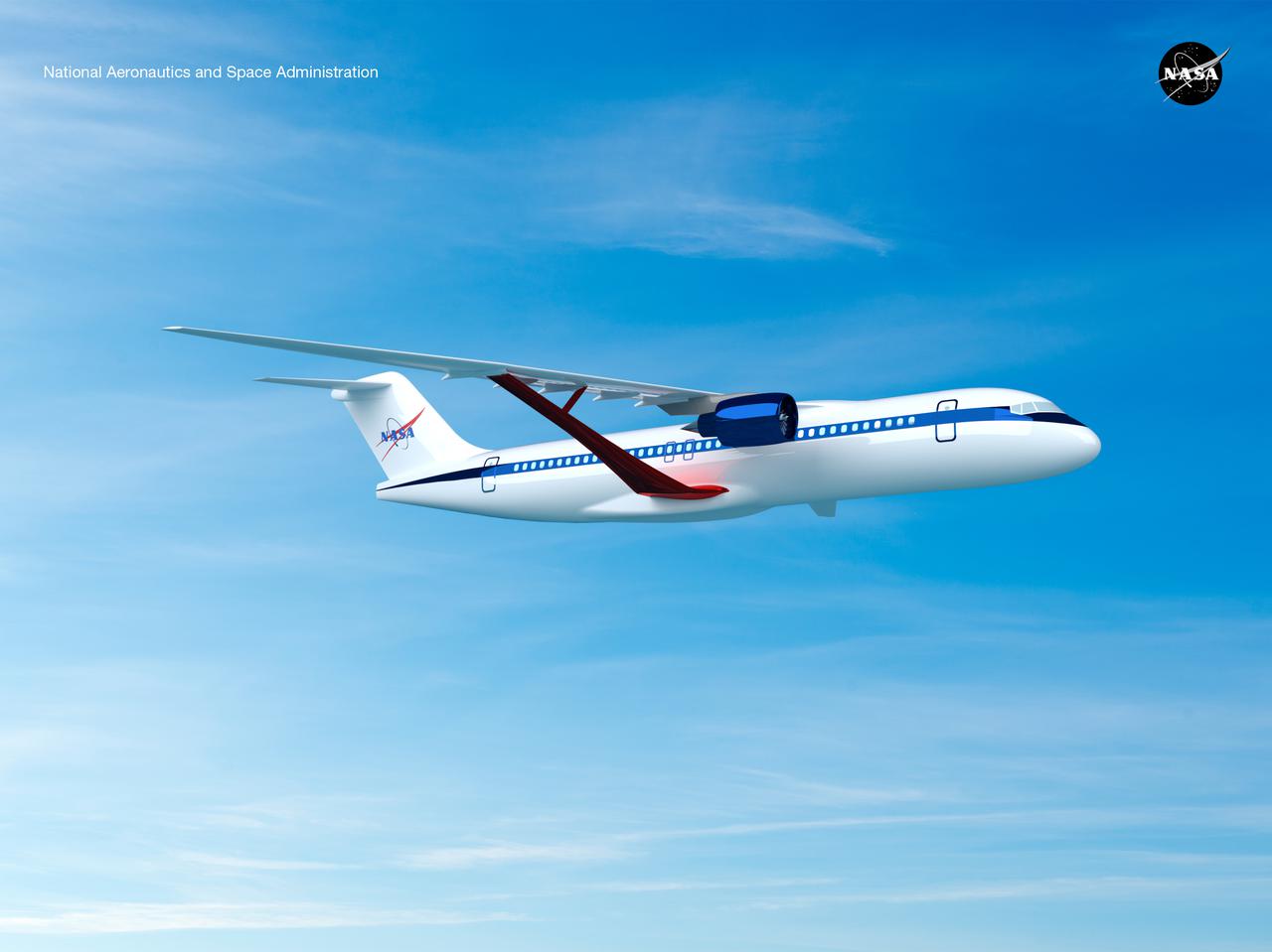
Notice anything different about the wings on this airliner? This conceptual truss-braced wing narrowbody is an aircraft with a 170ft span folding wing. By utilizing trusses, the aircraft can have longer, thinner wings with greater aspect ratios. This, in turn, translates into less drag and 5-10% less fuel burned. The Transonic Truss-Braced Wing aircraft originated from a joint effort by NASA and Boeing to develop subsonic commercial transport concepts – meeting NASA-defined metrics in terms of reduced noise, emissions, and fuel consumption. The design is currently undergoing wind tunnel testing and other studies by NASA researchers.
Notice anything different about the wings on this airliner? This conceptual truss-braced wing narrowbody is an aircraft with a 170ft span folding wing. By utilizing trusses, the aircraft can have longer, thinner wings with greater aspect ratios. This, in turn, translates into less drag and 5-10% less fuel burned. The Transonic Truss-Braced Wing aircraft originated from a joint effort by NASA and Boeing to develop subsonic commercial transport concepts – meeting NASA-defined metrics in terms of reduced noise, emissions, and fuel consumption. The design is currently undergoing wind tunnel testing and other studies by NASA researchers.
Notice anything different about the wings on this airliner? This conceptual truss-braced wing narrowbody is an aircraft with a 170ft span folding wing. By utilizing trusses, the aircraft can have longer, thinner wings with greater aspect ratios. This, in turn, translates into less drag and 5-10% less fuel burned. The Transonic Truss-Braced Wing aircraft originated from a joint effort by NASA and Boeing to develop subsonic commercial transport concepts – meeting NASA-defined metrics in terms of reduced noise, emissions, and fuel consumption. The design is currently undergoing wind tunnel testing and other studies by NASA researchers.
Notice anything different about the wings on this airliner? This conceptual truss-braced wing narrowbody is an aircraft with a 170ft span folding wing. By utilizing trusses, the aircraft can have longer, thinner wings with greater aspect ratios. This, in turn, translates into less drag and 5-10% less fuel burned. The Transonic Truss-Braced Wing aircraft originated from a joint effort by NASA and Boeing to develop subsonic commercial transport concepts – meeting NASA-defined metrics in terms of reduced noise, emissions, and fuel consumption. The design is currently undergoing wind tunnel testing and other studies by NASA researchers.
Notice anything different about the wings on this airliner? This conceptual truss-braced wing narrowbody is an aircraft with a 170ft span folding wing. By utilizing trusses, the aircraft can have longer, thinner wings with greater aspect ratios. This, in turn, translates into less drag and 5-10% less fuel burned. The Transonic Truss-Braced Wing aircraft originated from a joint effort by NASA and Boeing to develop subsonic commercial transport concepts – meeting NASA-defined metrics in terms of reduced noise, emissions, and fuel consumption. The design is currently undergoing wind tunnel testing and other studies by NASA researchers.
Notice anything different about the wings on this airliner? This conceptual truss-braced wing narrowbody is an aircraft with a 170ft span folding wing. By utilizing trusses, the aircraft can have longer, thinner wings with greater aspect ratios. This, in turn, translates into less drag and 5-10% less fuel burned. The Transonic Truss-Braced Wing aircraft originated from a joint effort by NASA and Boeing to develop subsonic commercial transport concepts – meeting NASA-defined metrics in terms of reduced noise, emissions, and fuel consumption. The design is currently undergoing wind tunnel testing and other studies by NASA researchers.
Notice anything different about the wings on this airliner? This conceptual truss-braced wing narrowbody is an aircraft with a 170ft span folding wing. By utilizing trusses, the aircraft can have longer, thinner wings with greater aspect ratios. This, in turn, translates into less drag and 5-10% less fuel burned. The Transonic Truss-Braced Wing aircraft originated from a joint effort by NASA and Boeing to develop subsonic commercial transport concepts – meeting NASA-defined metrics in terms of reduced noise, emissions, and fuel consumption. The design is currently undergoing wind tunnel testing and other studies by NASA researchers.
Notice anything different about the wings on this airliner? This conceptual truss-braced wing narrowbody is an aircraft with a 170ft span folding wing. By utilizing trusses, the aircraft can have longer, thinner wings with greater aspect ratios. This, in turn, translates into less drag and 5-10% less fuel burned. The Transonic Truss-Braced Wing aircraft originated from a joint effort by NASA and Boeing to develop subsonic commercial transport concepts – meeting NASA-defined metrics in terms of reduced noise, emissions, and fuel consumption. The design is currently undergoing wind tunnel testing and other studies by NASA researchers.
Notice anything different about the wings on this airliner? This conceptual truss-braced wing narrowbody is an aircraft with a 170ft span folding wing. By utilizing trusses, the aircraft can have longer, thinner wings with greater aspect ratios. This, in turn, translates into less drag and 5-10% less fuel burned. The Transonic Truss-Braced Wing aircraft originated from a joint effort by NASA and Boeing to develop subsonic commercial transport concepts – meeting NASA-defined metrics in terms of reduced noise, emissions, and fuel consumption. The design is currently undergoing wind tunnel testing and other studies by NASA researchers.
Notice anything different about the wings on this airliner? This conceptual truss-braced wing narrowbody is an aircraft with a 170ft span folding wing. By utilizing trusses, the aircraft can have longer, thinner wings with greater aspect ratios. This, in turn, translates into less drag and 5-10% less fuel burned. The Transonic Truss-Braced Wing aircraft originated from a joint effort by NASA and Boeing to develop subsonic commercial transport concepts – meeting NASA-defined metrics in terms of reduced noise, emissions, and fuel consumption. The design is currently undergoing wind tunnel testing and other studies by NASA researchers.

Engineering technician Jeff Howell mounts conventional strain gauges to the Mock Truss-Braced Wing 10-foot model at NASA’s Armstrong Flight Research Center in Edwards, California. The conventional system data will be compared the Fiber Optic Sensing System developed at the center on the same wing to see how well the testing methods match.
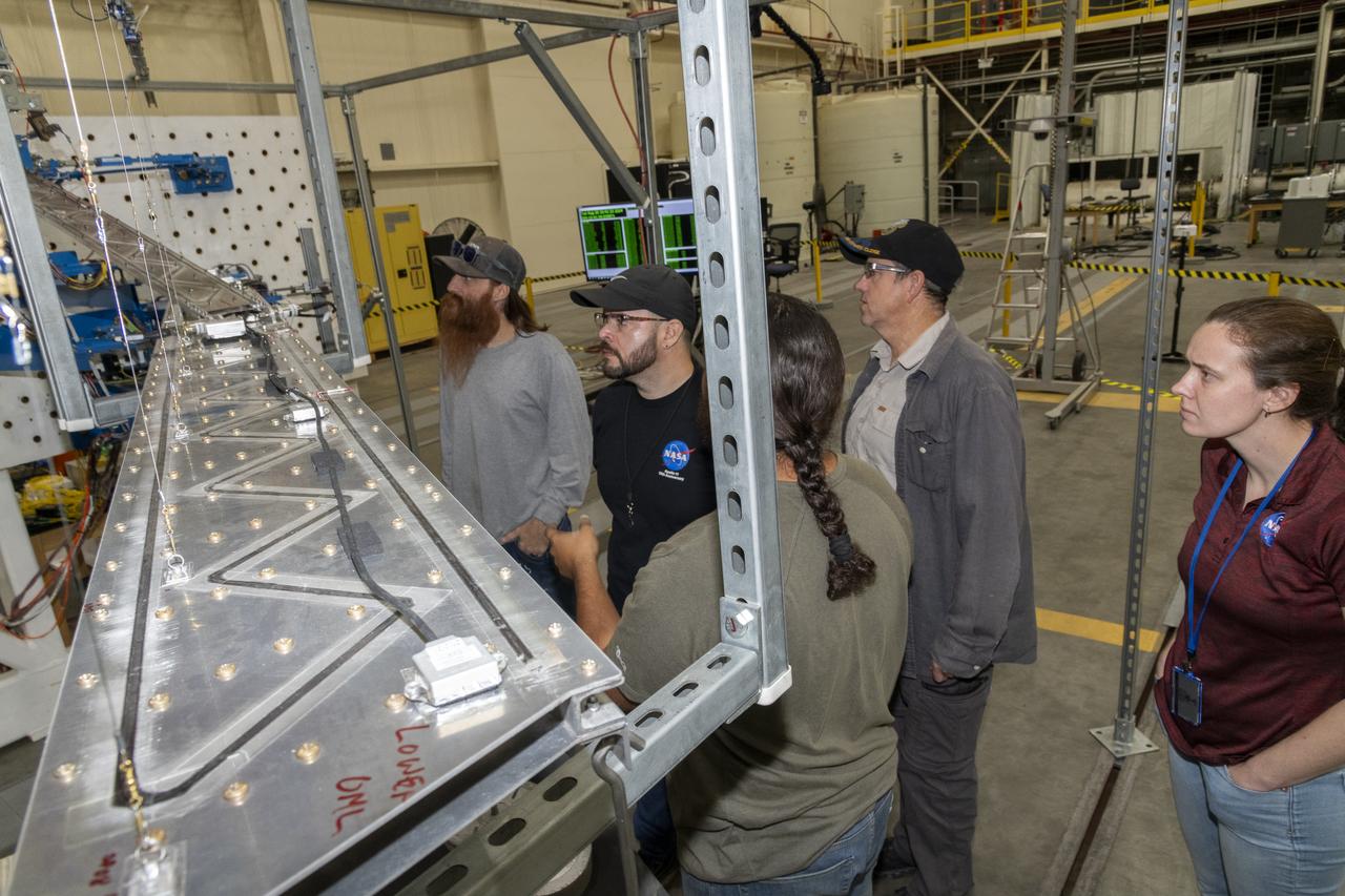
Researchers test a 10-foot Mock Truss-Braced Wing at NASA’s Armstrong Flight Research Center in Edwards, California. The test team makes observations between tests. The aircraft concept involves a wing braced on an aircraft using diagonal struts that also add lift and could result in significantly improved aerodynamics.
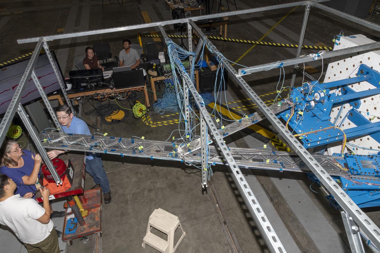
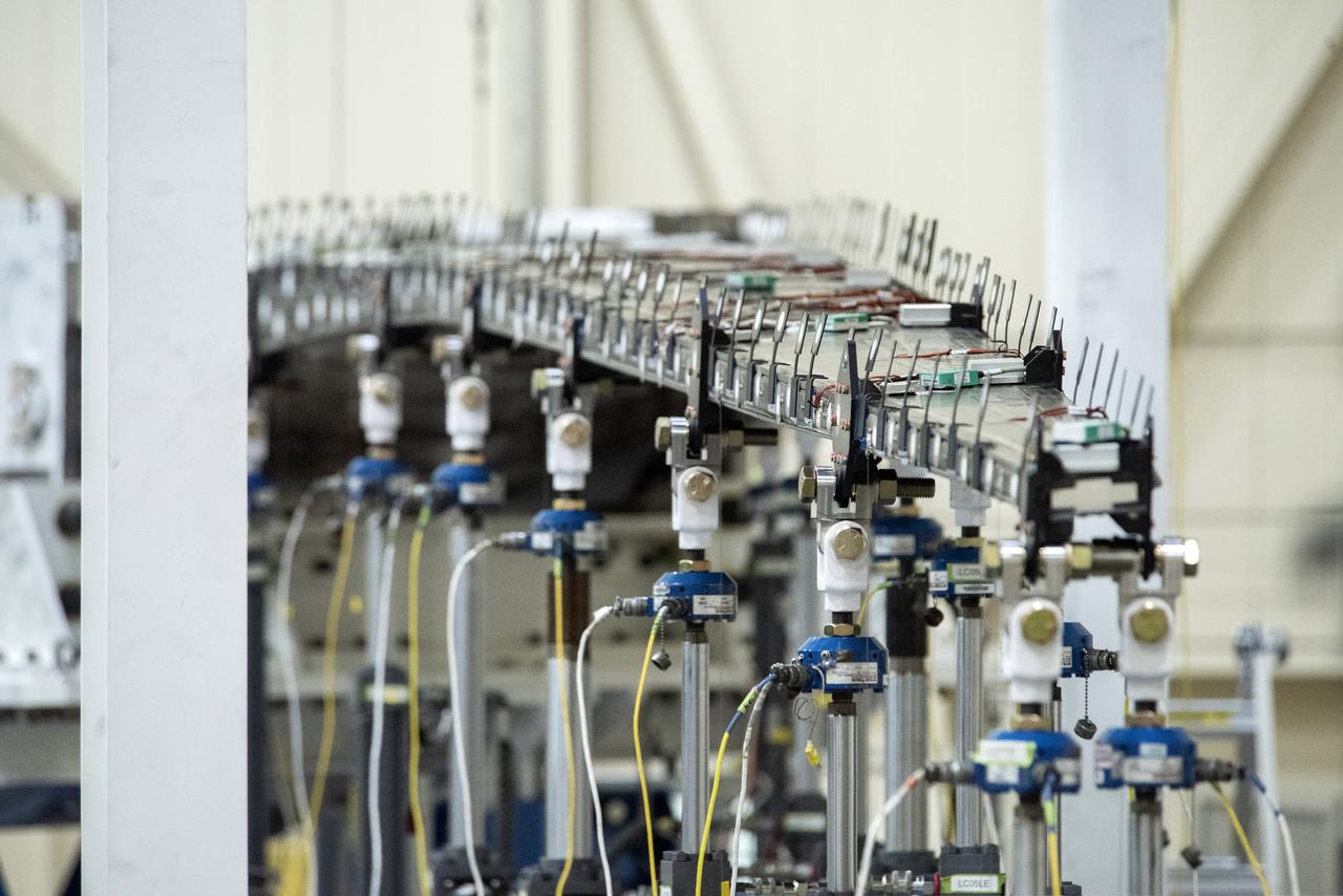
Researchers test a 10-foot Mock Truss-Braced Wing at NASA’s Armstrong Flight Research Center in Edwards, California. A view from above shows the test structure, the wing, and the strut. The aircraft concept involves a wing braced on an aircraft using diagonal struts that also add lift and could result in significantly improved aerodynamics.
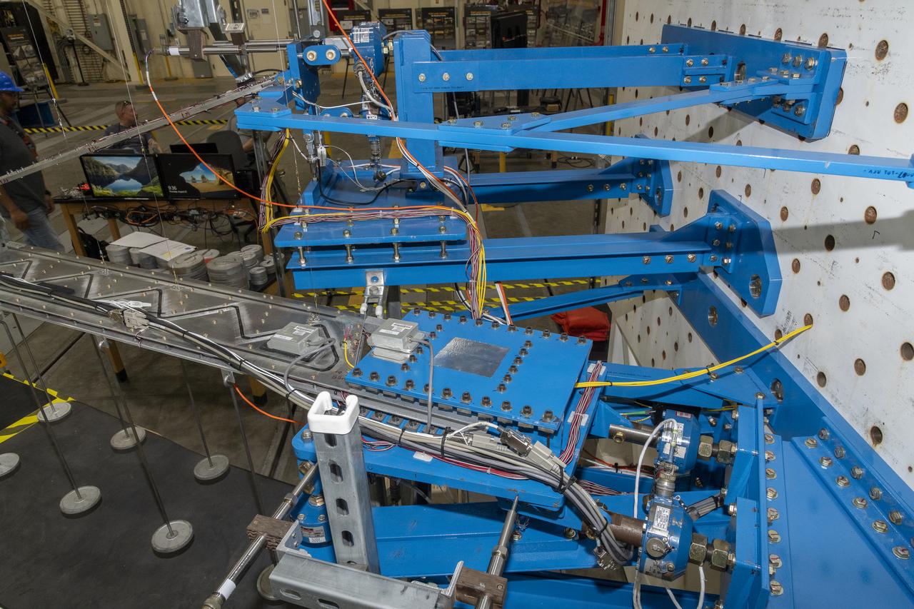
Researchers test a 10-foot Mock Truss-Braced Wing at NASA’s Armstrong Flight Research Center in Edwards, California. The infrastructure, in blue, holds the wing and truss and enables the test. The aircraft concept involves a wing braced on an aircraft using diagonal struts that also add lift and could result in significantly improved aerodynamics.
Instrumentation of the wing and strut that comprise the Mock Truss-Braced Wing 10-foot model are complete at NASA’s Armstrong Flight Research Center in Edwards, California.

From left to right, Savitri Thomas, management and program analyst; Ales-Cia Winsley, lead Space Launch System avionics engineer; Alexandra Philip, metrology engineer, at NASA’s Kennedy Space Center in Florida, speak on Friday, Sept. 20, 2024, to young women, ages 11 to 18, from the Atlanta, Georgia area, with interests in STEM (science, technology, engineering, and math). NASA Kennedy hosted the Delta Air Lines’ Women Inspiring Our Next Generation (WING) flight to showcase various women-led STEM careers available at the Florida spaceport.
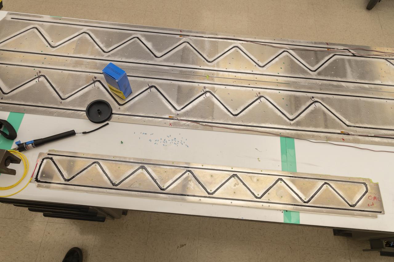
Wally Hargis, left, and Ted Powers complete preparations for testing the Passive Aeroelastic Tailored wing.
The Passive Aeroelastic Tailored wing is tested in a fixture at the NASA Armstrong Flight Test Center’s Flight Loads Laboratory in California.

Eric Sinks, left, and Ron Haraguchi work through a challenge with the wiring from the Passive Aeroelastic Tailored wing to the test fixture.
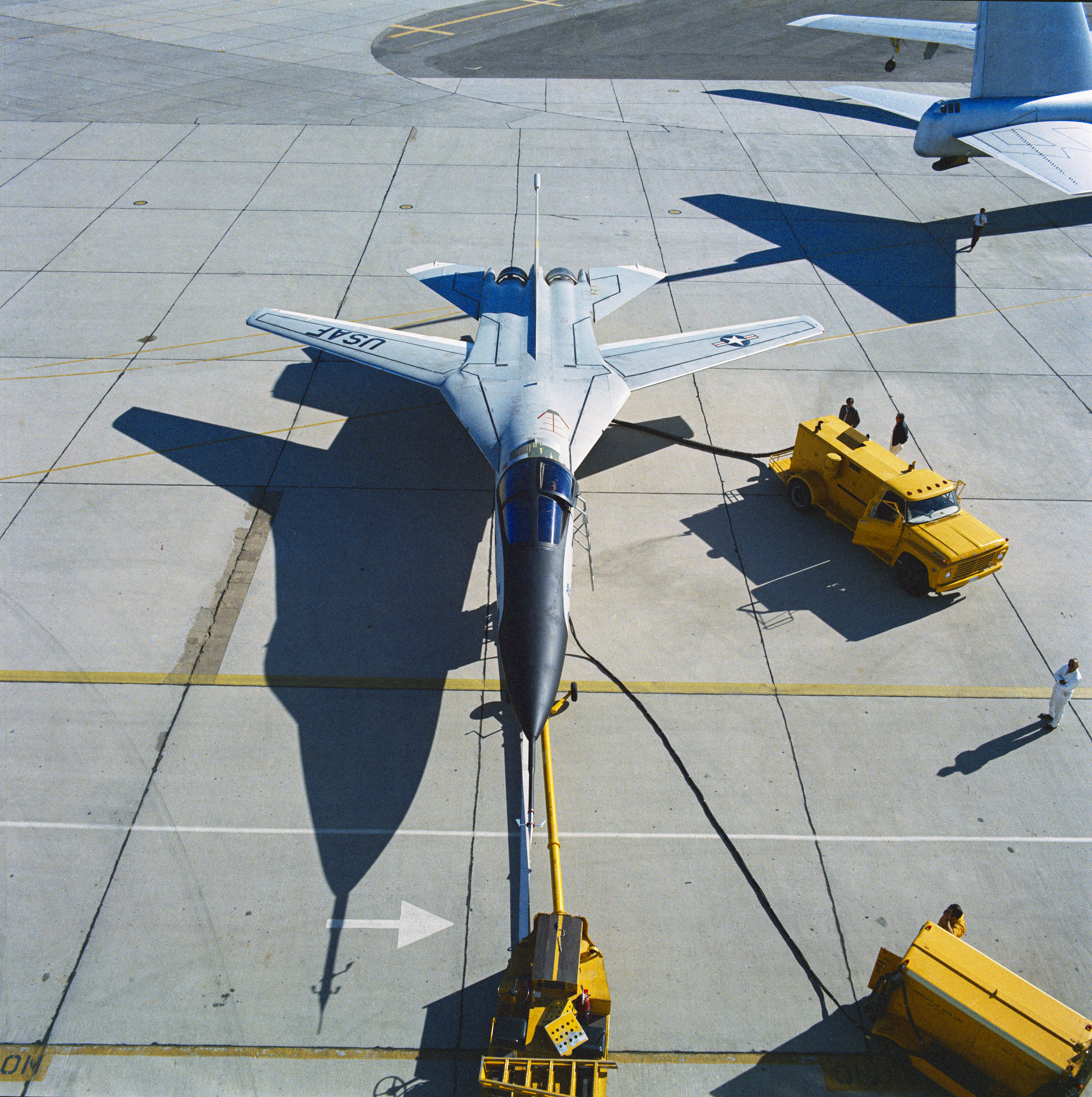
The F-111B with its wings swept to their maximum angle. It carried the Mission Adaptive Wing, a single-piece composite structure with leading and trailing edges that could be lowered or raised in flight.
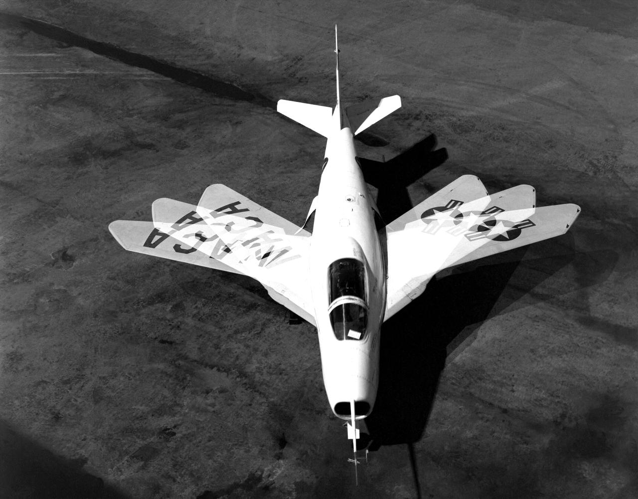
The Bell X-5 swings its wings in this multiple exposure photograph. Variable-sweep wing technology later appeared on the F-111, F-14 and B-1.
Researchers test a 10-foot Mock Truss-Braced Wing at NASA’s Armstrong Flight Research Center in Edwards, California. From left, ground vibration test director Ben Park, Natalie Spivey, and Samson Truong, prepare for a vibration test. The aircraft concept involves a wing braced on an aircraft using diagonal struts that also add lift and could result in significantly improved aerodynamics.
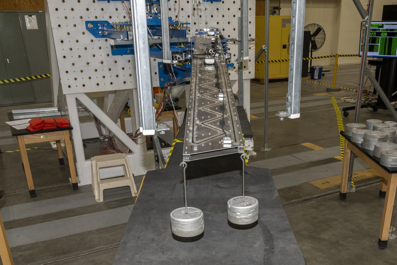
Researchers test a 10-foot Mock Truss-Braced Wing at NASA’s Armstrong Flight Research Center in Edwards, California. Weights are added to the wingtip to apply stress used to determine its limits. The aircraft concept involves a wing braced on an aircraft using diagonal struts that also add lift and could result in significantly improved aerodynamics.

Application of blowing-type boundry-layer control to the leading-and trailing-edge flaps of a Change Vought XF8U-1 wing
6x6 wind tunnel test on the effects of wing sweep.
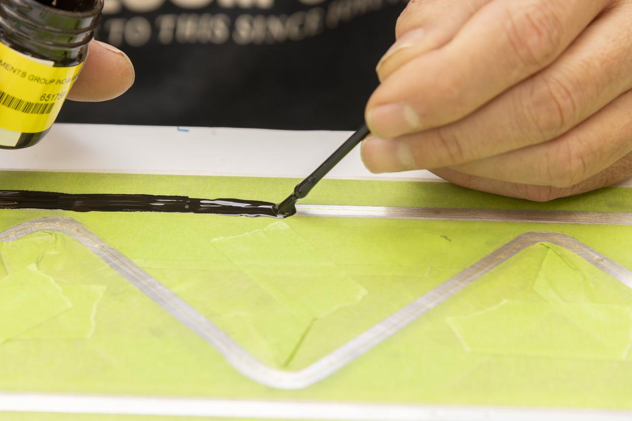
An epoxy is applied to adhere the fiber optic sensor installation on the Mock Truss-Braced Wing 10-foot model at NASA’s Armstrong Flight Research Center in Edwards, California.
Notice anything different about the wings on this airliner? This conceptual truss-braced wing narrowbody is an aircraft with a 170ft span folding wing. By utilizing trusses, the aircraft can have longer, thinner wings with greater aspect ratios. This, in turn, translates into less drag and 5-10% less fuel burned. The Transonic Truss-Braced Wing aircraft originated from a joint effort by NASA and Boeing to develop subsonic commercial transport concepts – meeting NASA-defined metrics in terms of reduced noise, emissions, and fuel consumption. The design is currently undergoing wind tunnel testing and other studies by NASA researchers.
Notice anything different about the wings on this airliner? This conceptual truss-braced wing narrowbody is an aircraft with a 170ft span folding wing. By utilizing trusses, the aircraft can have longer, thinner wings with greater aspect ratios. This, in turn, translates into less drag and 5-10% less fuel burned. The Transonic Truss-Braced Wing aircraft originated from a joint effort by NASA and Boeing to develop subsonic commercial transport concepts – meeting NASA-defined metrics in terms of reduced noise, emissions, and fuel consumption. The design is currently undergoing wind tunnel testing and other studies by NASA researchers.
This broad view of the Flight Loads Laboratory at NASA’s Armstrong Flight Research Center in California shows the test set up for the high-aspect ratio Passive Aeroelastic Tailored wing.
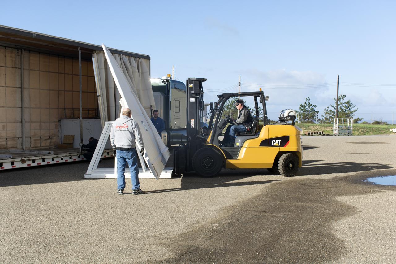
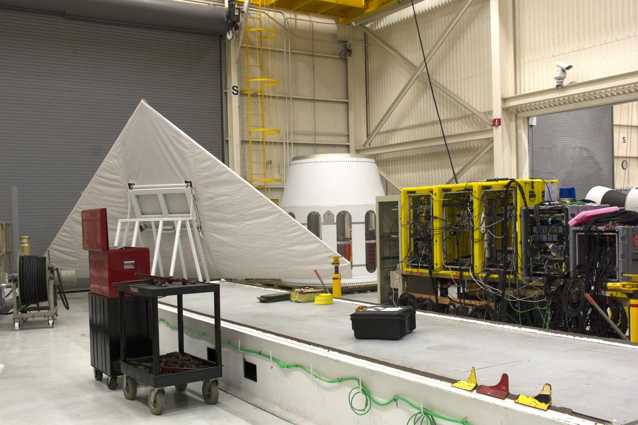
Workers transfer the wing for the Orbital ATK Pegasus XL rocket from a truck to a forklift at Building 1555 at Vandenberg Air Force Base in California. The rocket is being prepared for NASA's Ionospheric Connection Explorer, or ICON, mission. ICON will launch from the Kwajalein Atoll aboard the Pegasus XL on Dec. 8, 2017. ICON will study the frontier of space - the dynamic zone high in Earth's atmosphere where terrestrial weather from below meets space weather above. The explorer will help determine the physics of Earth's space environment and pave the way for mitigating its effects on our technology, communications systems and society.
The wing for the Orbital ATK Pegasus XL rocket was offloaded from a truck and transporter to Building 1555 at Vandenberg Air Force Base in California. The rocket is being prepared for NASA's Ionospheric Connection Explorer, or ICON, mission. ICON will launch from the Kwajalein Atoll aboard the Pegasus XL on Dec. 8, 2017. ICON will study the frontier of space - the dynamic zone high in Earth's atmosphere where terrestrial weather from below meets space weather above. The explorer will help determine the physics of Earth's space environment and pave the way for mitigating its effects on our technology, communications systems and society.
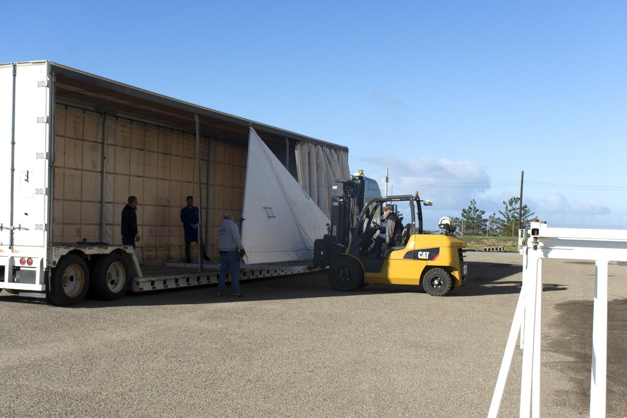
Workers unload the wing for the Orbital ATK Pegasus XL rocket from a truck at Building 1555 at Vandenberg Air Force Base in California. The rocket is being prepared for NASA's Ionospheric Connection Explorer, or ICON, mission. ICON will launch from the Kwajalein Atoll aboard the Pegasus XL on Dec. 8, 2017. ICON will study the frontier of space - the dynamic zone high in Earth's atmosphere where terrestrial weather from below meets space weather above. The explorer will help determine the physics of Earth's space environment and pave the way for mitigating its effects on our technology, communications systems and society.
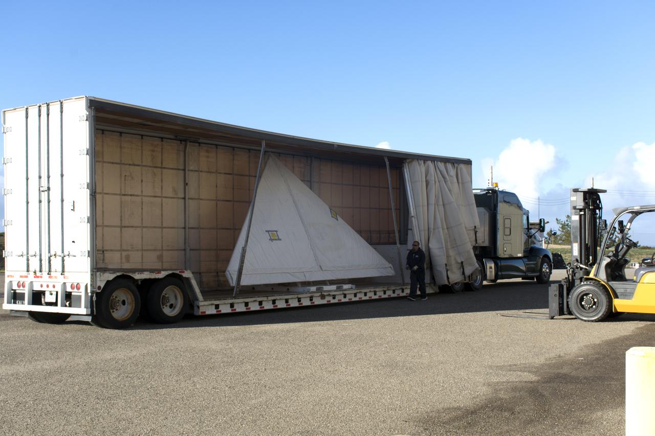
The wing for the Orbital ATK Pegasus XL rocket arrives by truck at Building 1555 at Vandenberg Air Force Base in California. The Pegasus rocket is being prepared for NASA's Ionospheric Connection Explorer, or ICON, mission. ICON will launch from the Kwajalein Atoll aboard the Pegasus XL on Dec. 8, 2017. ICON will study the frontier of space - the dynamic zone high in Earth's atmosphere where terrestrial weather from below meets space weather above. The explorer will help determine the physics of Earth's space environment and pave the way for mitigating its effects on our technology, communications systems and society.
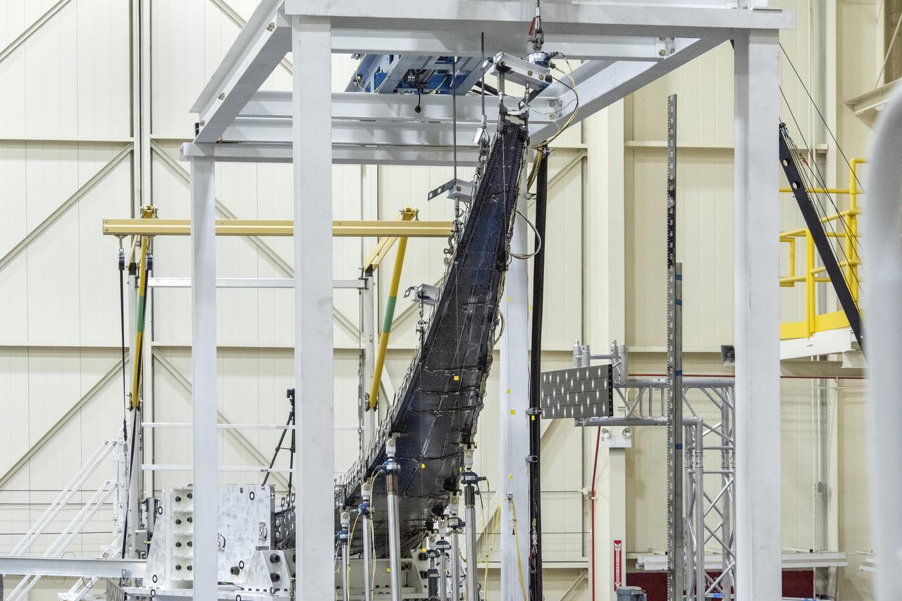
The Passive Aeroelastic Tailored (PAT) wing bends under pressure from the highest loads applied during testing at NASA’s Armstrong Flight Research Center in California.
Ted Powers makes an adjustment to the Passive Aeroelastic Tailored (PAT) wing testing apparatus at NASA’s Armstrong Flight Research Center in California.
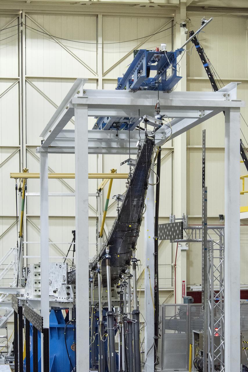
The Passive Aeroelastic Tailored (PAT) wing bends under pressure from the highest loads applied during testing at NASA’s Armstrong Flight Research Center in California.
Notice anything different about the wings on this airliner? This conceptual truss-braced wing narrowbody is an aircraft with a 170ft span folding wing. By utilizing trusses, the aircraft can have longer, thinner wings with greater aspect ratios. This, in turn, translates into less drag and 5-10% less fuel burned. The Transonic Truss-Braced Wing aircraft originated from a joint effort by NASA and Boeing to develop subsonic commercial transport concepts – meeting NASA-defined metrics in terms of reduced noise, emissions, and fuel consumption. The design is currently undergoing wind tunnel testing and other studies by NASA researchers.
Oblique Wing Research Aircraft in flight
Ted Powers, from left, Larry Hudson, Ron Haraguchi and Walter Hargis make adjustments to the Passive Aeroelastic Tailored (PAT) wing testing apparatus at NASA’s Armstrong Flight Research Center in California.
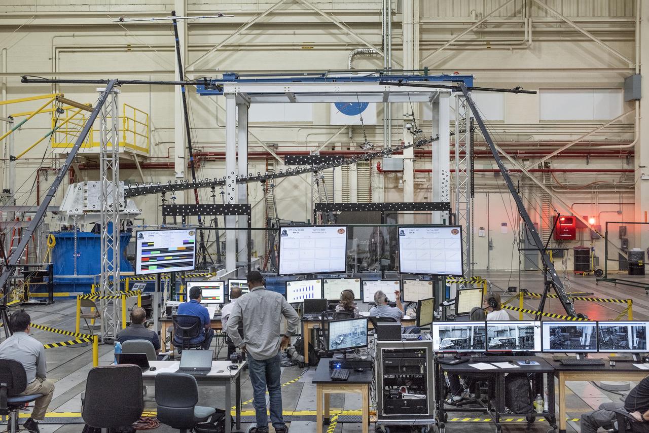
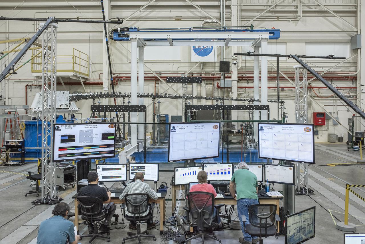
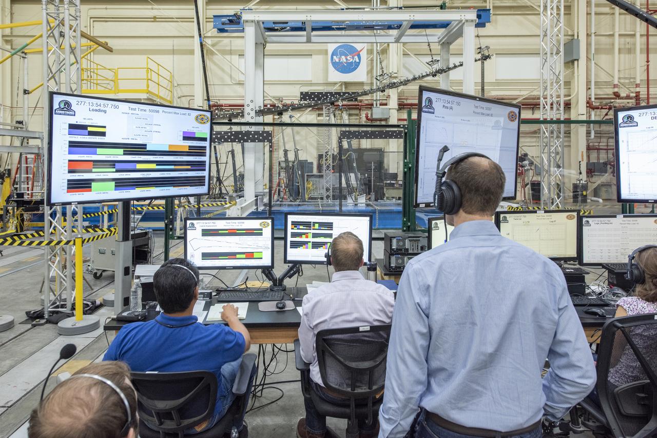
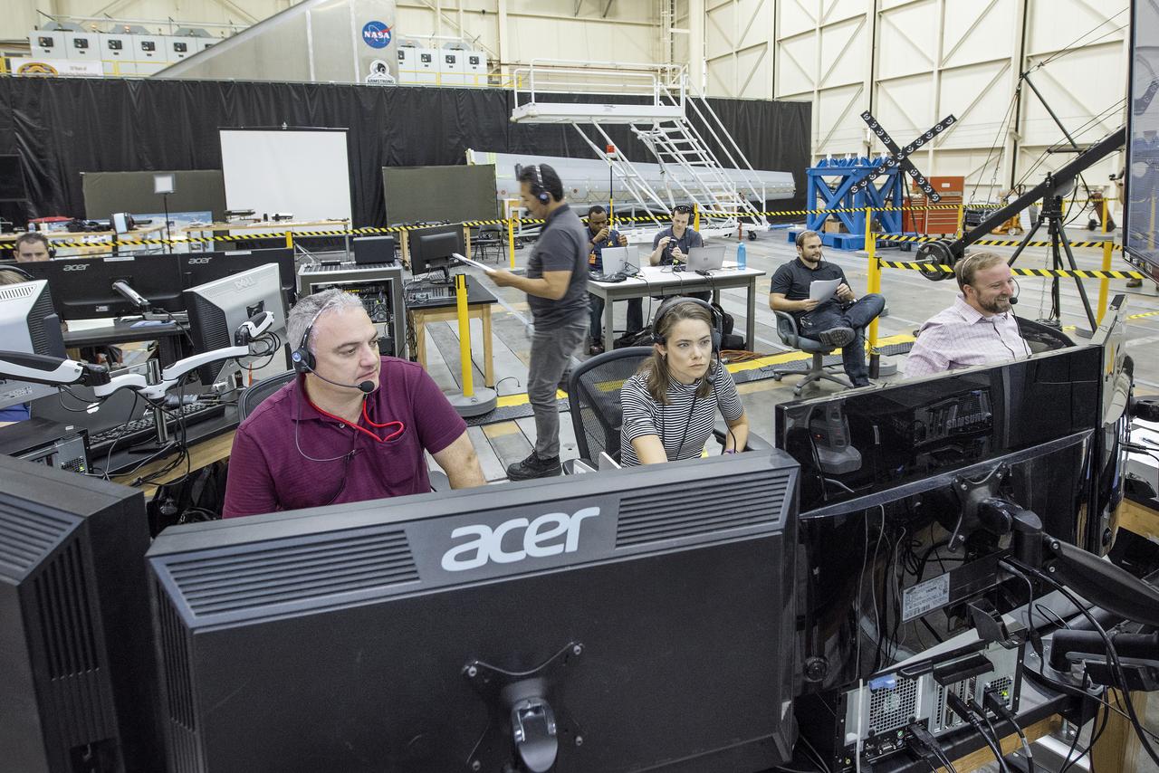
NASA’s Armstrong Flight Research Center and Langley Research Center staff members monitor a test of the Passive Aeroelastic Tailored (PAT) wing at NASA’s Armstrong Flight Research Center in California.
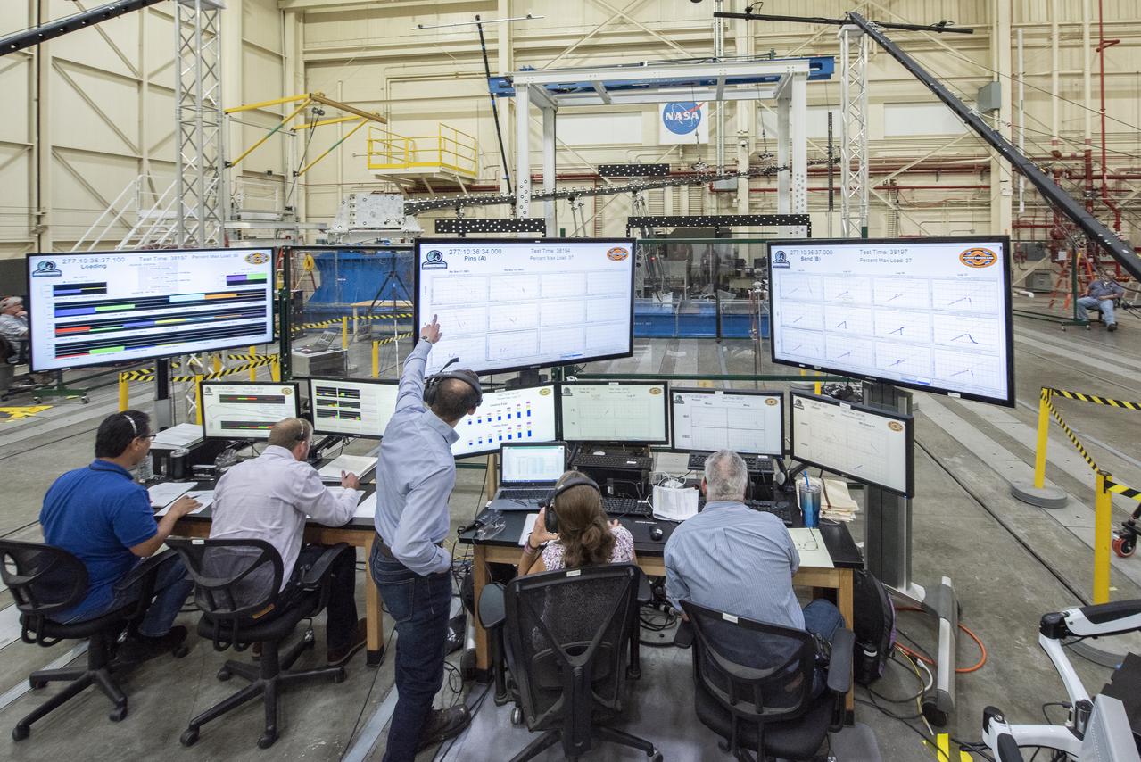
NASA’s Armstrong Flight Research Center and Langley Research Center staff members monitor a test of the Passive Aeroelastic Tailored (PAT) wing at NASA’s Armstrong Flight Research Center in California.
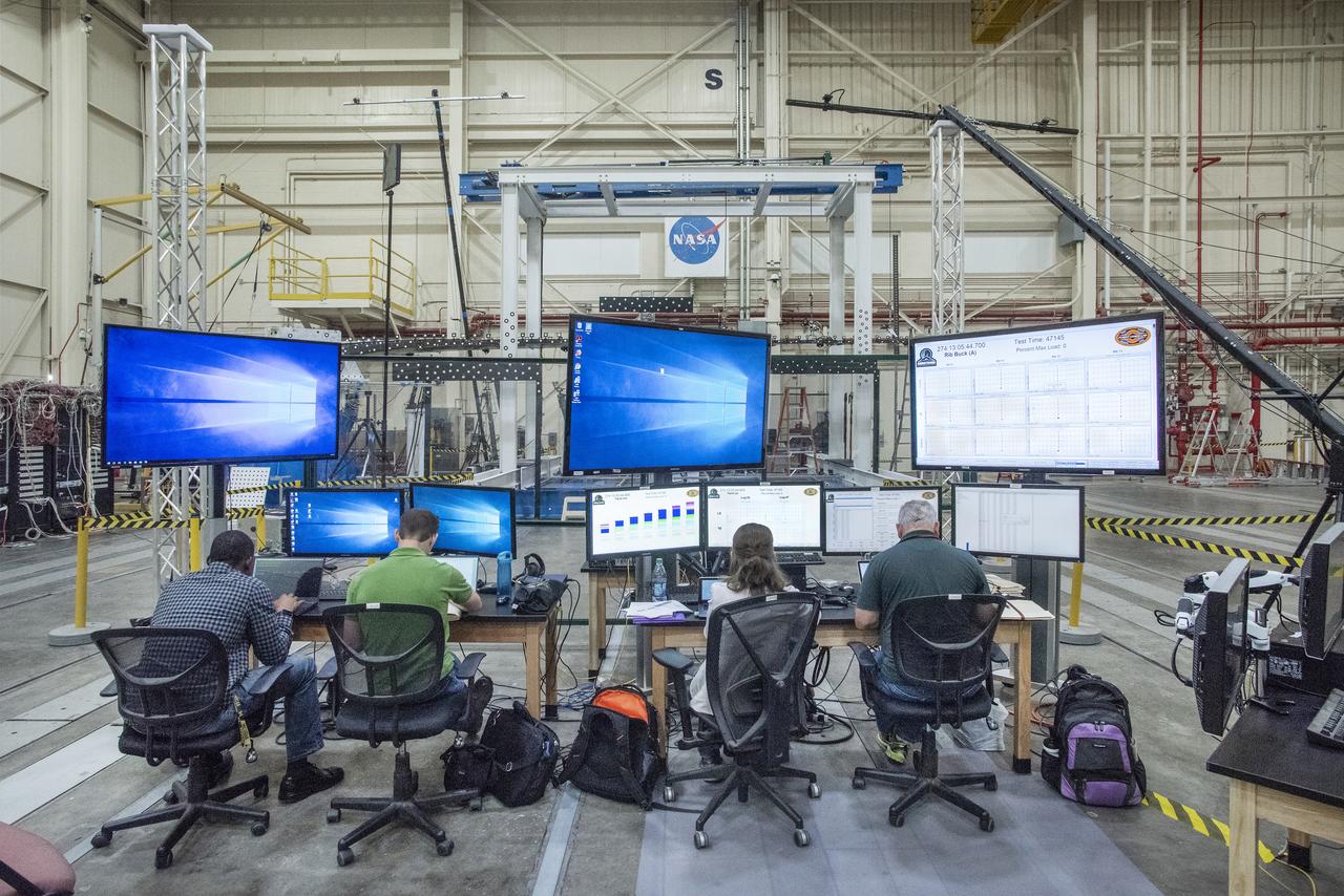
NASA’s Armstrong Flight Research Center and Langley Research Center staff members monitor a test of the Passive Aeroelastic Tailored (PAT) wing at NASA’s Armstrong Flight Research Center in California.
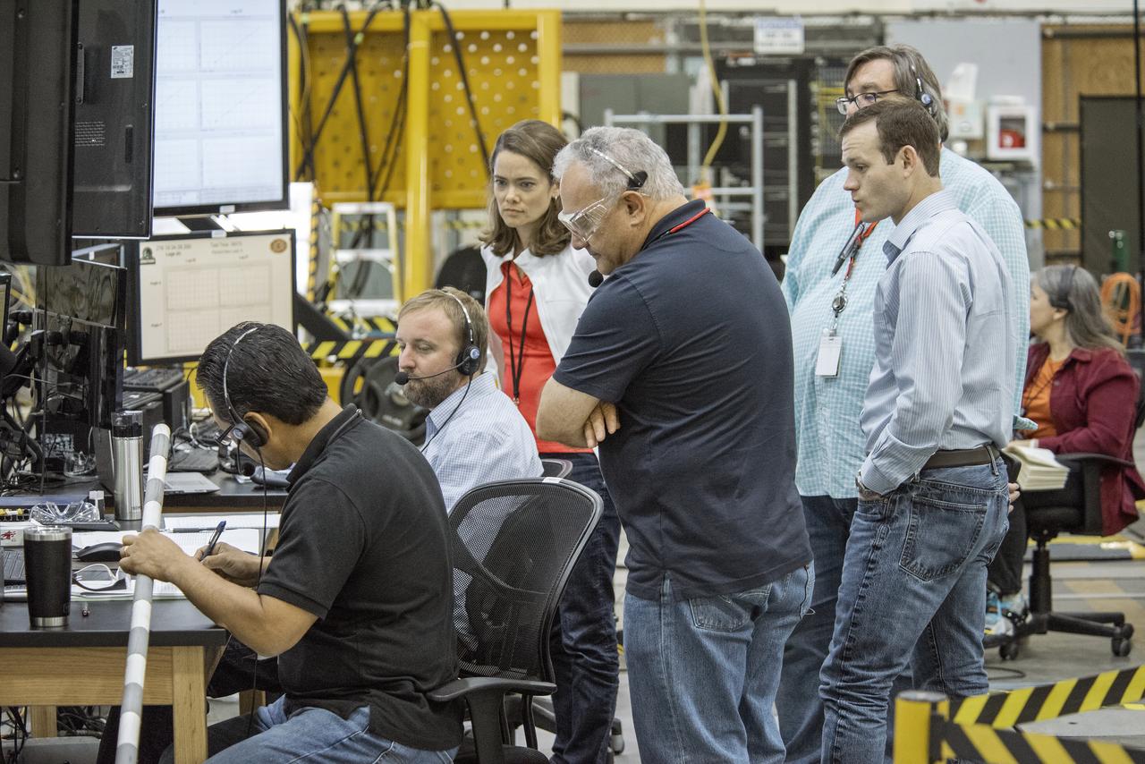
NASA’s Armstrong Flight Research Center and Langley Research Center staff members monitor a test of the Passive Aeroelastic Tailored (PAT) wing at NASA’s Armstrong Flight Research Center in California.
NASA’s Armstrong Flight Research Center and Langley Research Center staff members monitor a test of the Passive Aeroelastic Tailored (PAT) wing at NASA’s Armstrong Flight Research Center in California.
NASA’s Armstrong Flight Research Center and Langley Research Center staff members monitor a test of the Passive Aeroelastic Tailored (PAT) wing at NASA’s Armstrong Flight Research Center in California.
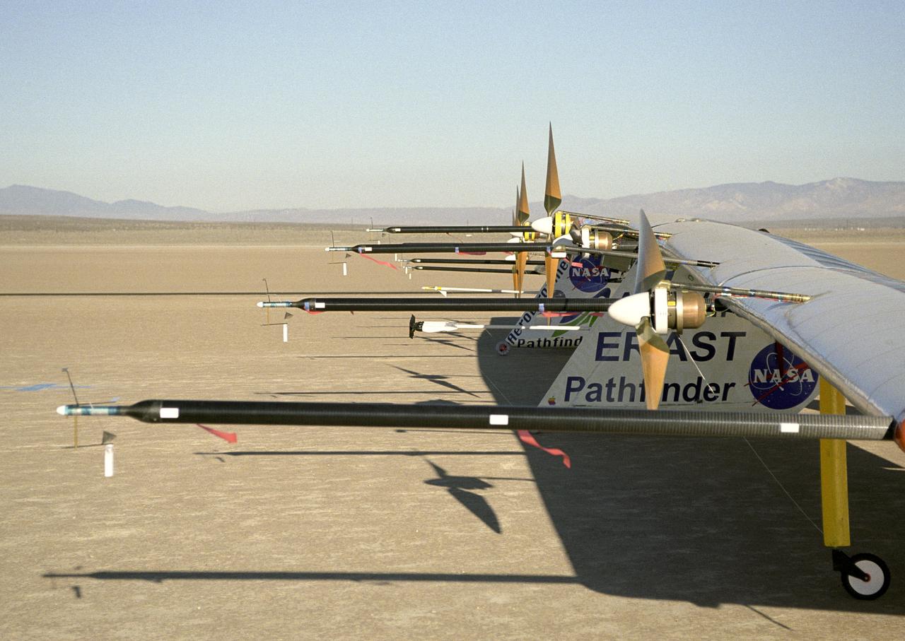
Sensitive instruments mounted on booms extending forward of the wing measure air turbulence and its effect on the stability of the Pathfinder-Plus solar-electric flying wing.
Engineering technician Jeff Howell removes thin pieces of tape from fiber used for a bonding process on the Mock Truss-Braced Wing 10-foot model at NASA’s Armstrong Flight Research Center in Edwards, California.
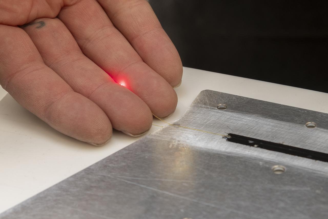
A red light confirms that the fiber of the Fiber Optic Sensing System installed on the Mock Truss-Braced Wing 10-foot model works as intended at NASA’s Armstrong Flight Research Center in Edwards, California. The fiber, which is about the thickness of a human hair, is part of a system that can provide strain information researchers can use to determine the model’s durability.

Matthew Sanchez attaches the strut and the wing to ensure they fit together as intended for a 10-foot model of the Transonic Truss-Braced Wing at NASA’s Armstrong Flight Research Center, in Edwards, California. The aircraft concept involves a wing braced on an aircraft using diagonal struts that also add lift and could result in significantly improved aerodynamics.
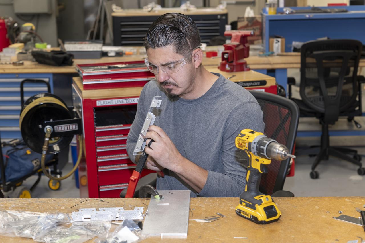
Matthew Sanchez assembles wing ribs for a 10-foot model of the Transonic Truss-Braced Wing at NASA’s Armstrong Flight Research Center, in Edwards, California. The aircraft concept involves a wing braced on an aircraft using diagonal struts that also add lift and could result in significantly improved aerodynamics.
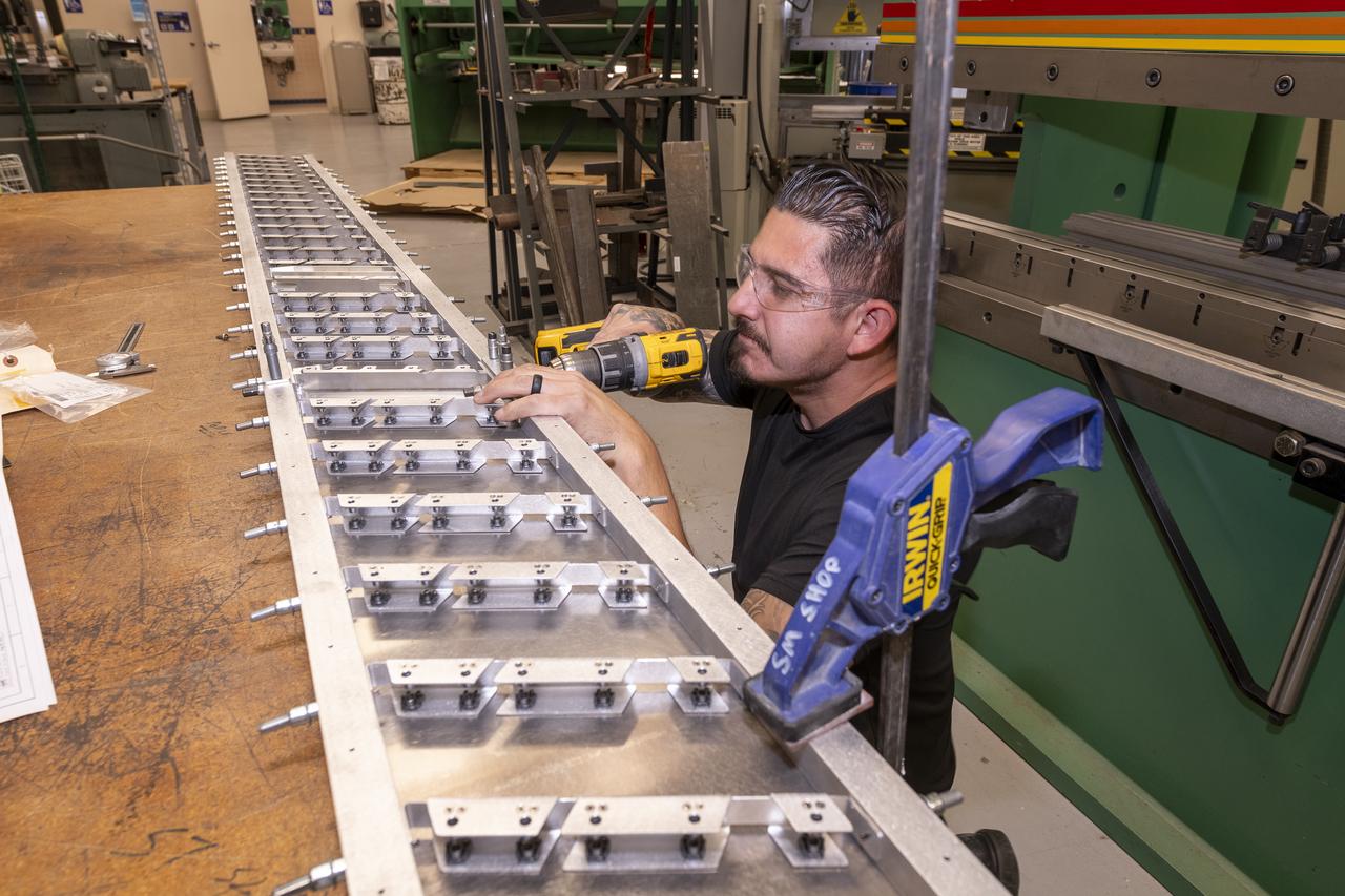
Matthew Sanchez assembles wing ribs to the 10-foot model of the Transonic Truss-Braced Wing at NASA’s Armstrong Flight Research Center, in Edwards, California. The aircraft concept involves a wing braced on an aircraft using diagonal struts that also add lift and could result in significantly improved aerodynamics.
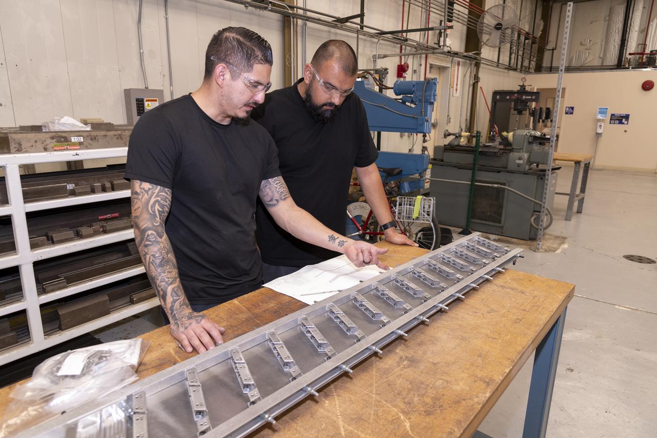
Matthew Sanchez, left, consults with Sal Navarro on assembling wing ribs to the 10-foot model of the Transonic Truss-Braced Wing at NASA’s Armstrong Flight Research Center, in Edwards, California. The aircraft concept involves a wing braced on an aircraft using diagonal struts that also add lift and could result in significantly improved aerodynamics.
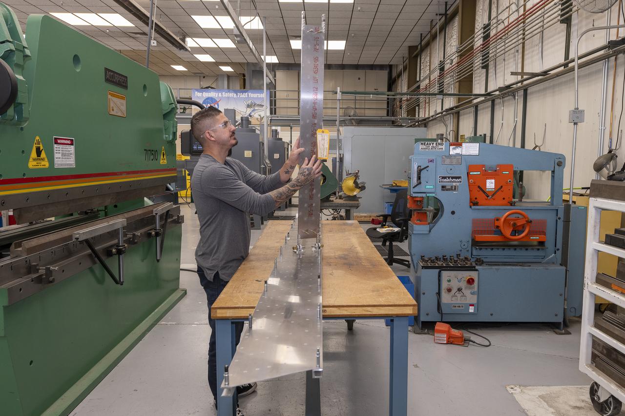
Matthew Sanchez attaches the strut and the wing to ensure they fit together as intended for a 10-foot model of the Transonic Truss-Braced Wing at NASA’s Armstrong Flight Research Center, in Edwards, California. The aircraft concept involves a wing braced on an aircraft using diagonal struts that also add lift and could result in significantly improved aerodynamics.
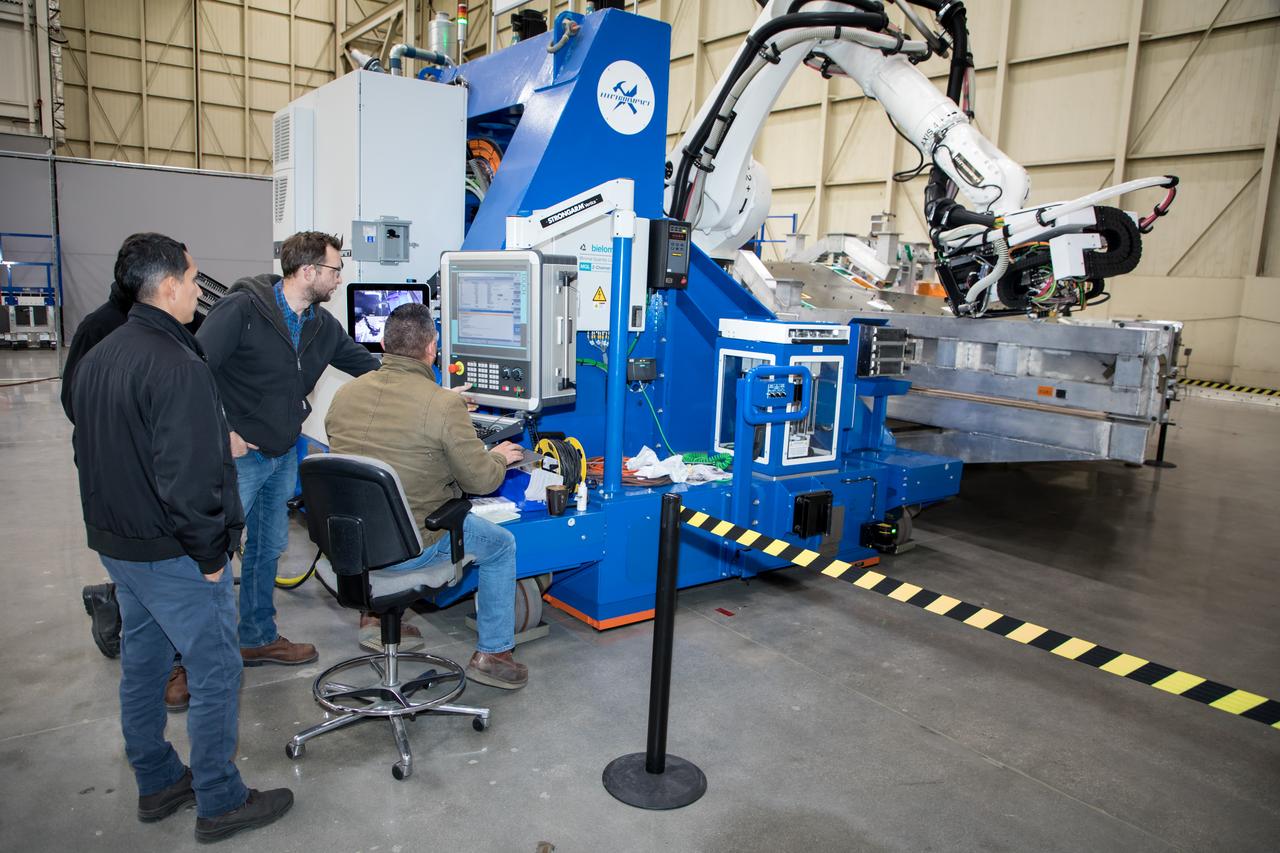
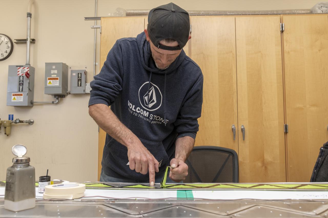
Lockheed Martin Photography By Garry Tice 1011 Lockheed Way, Palmdale, Ca. 93599 Event: SEG 410 Main Wing, COBRA Drillng Machine, Drilling Lower Wing Skins Date: 1/07/20 Additional Info:
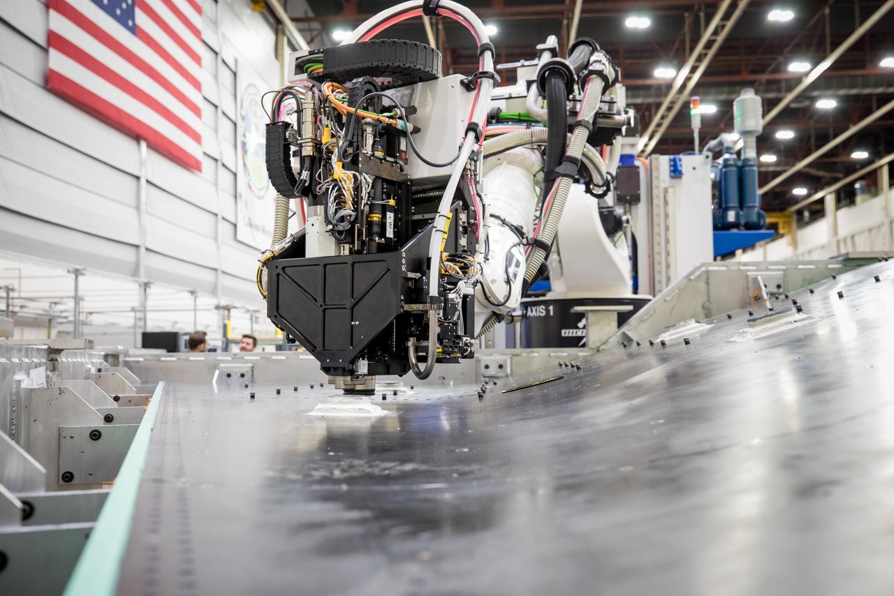
Lockheed Martin Photography By Garry Tice 1011 Lockheed Way, Palmdale, Ca. 93599 Event: SEG 410 Main Wing, COBRA Drillng Machine, Drilling Lower Wing Skins Date: 1/07/20 Additional Info: