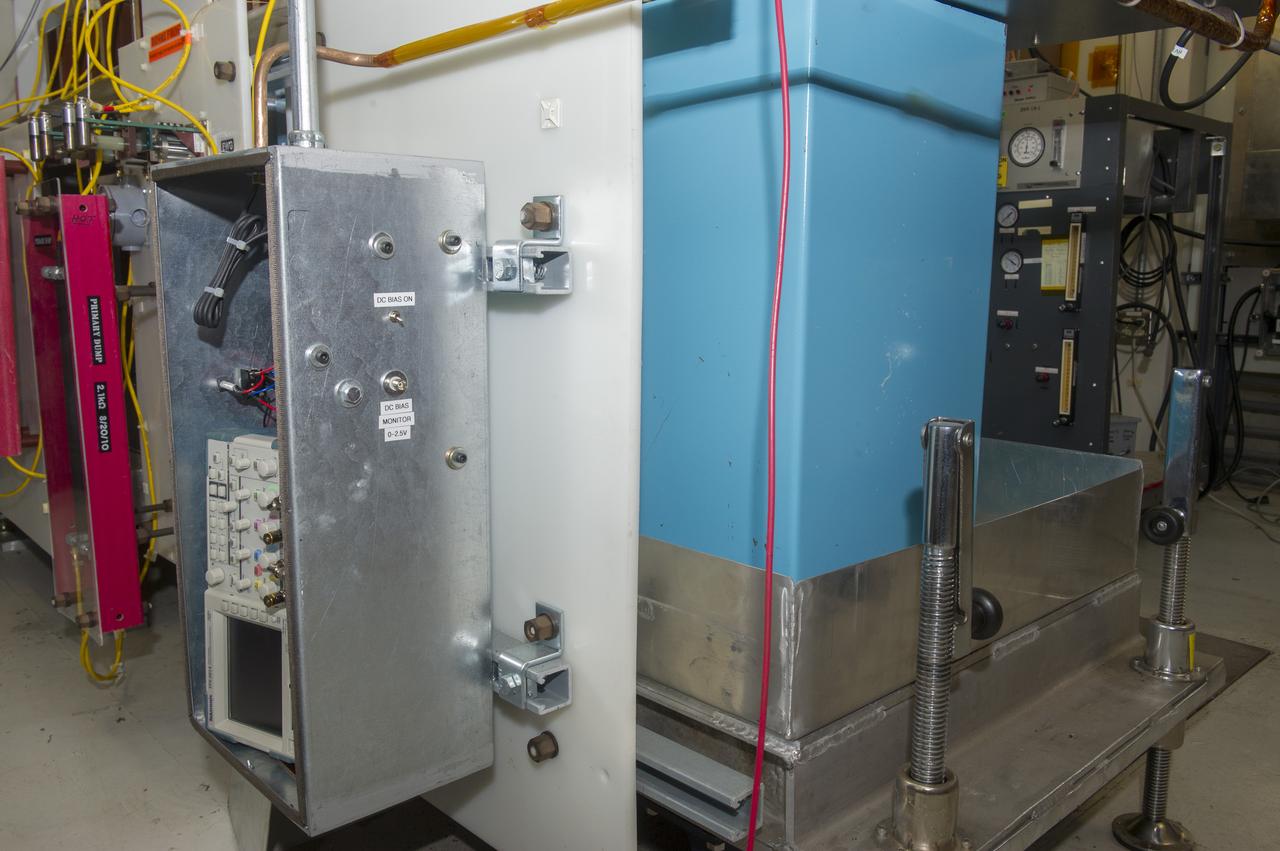
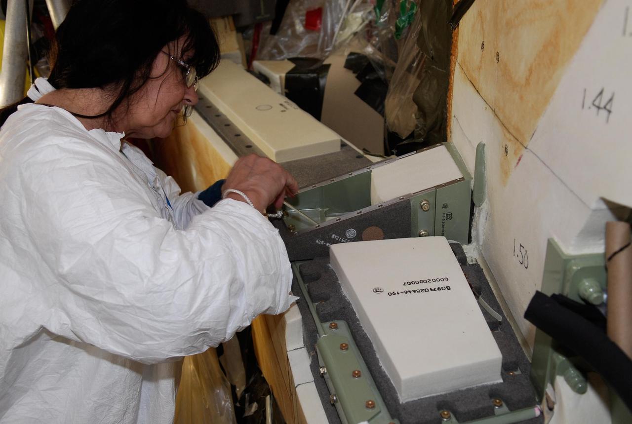
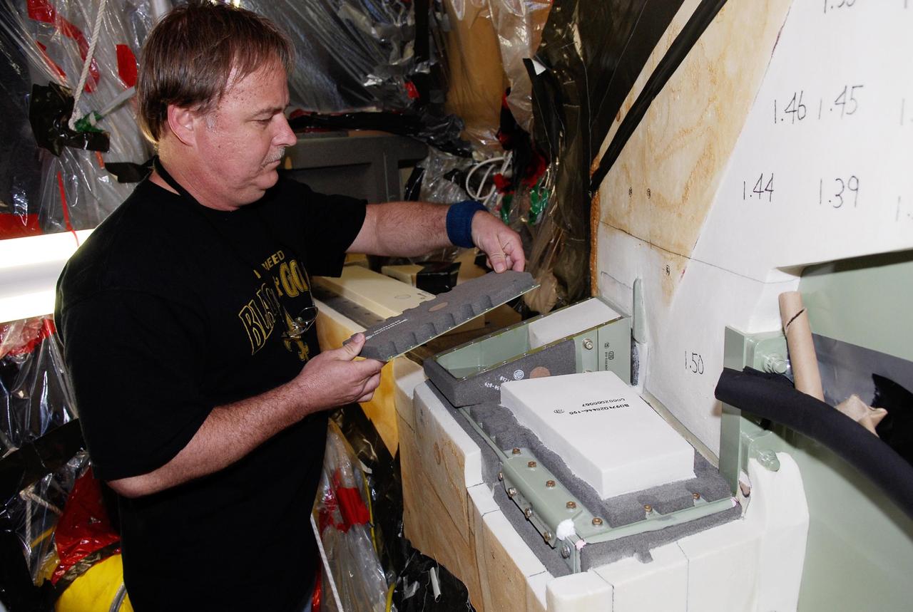
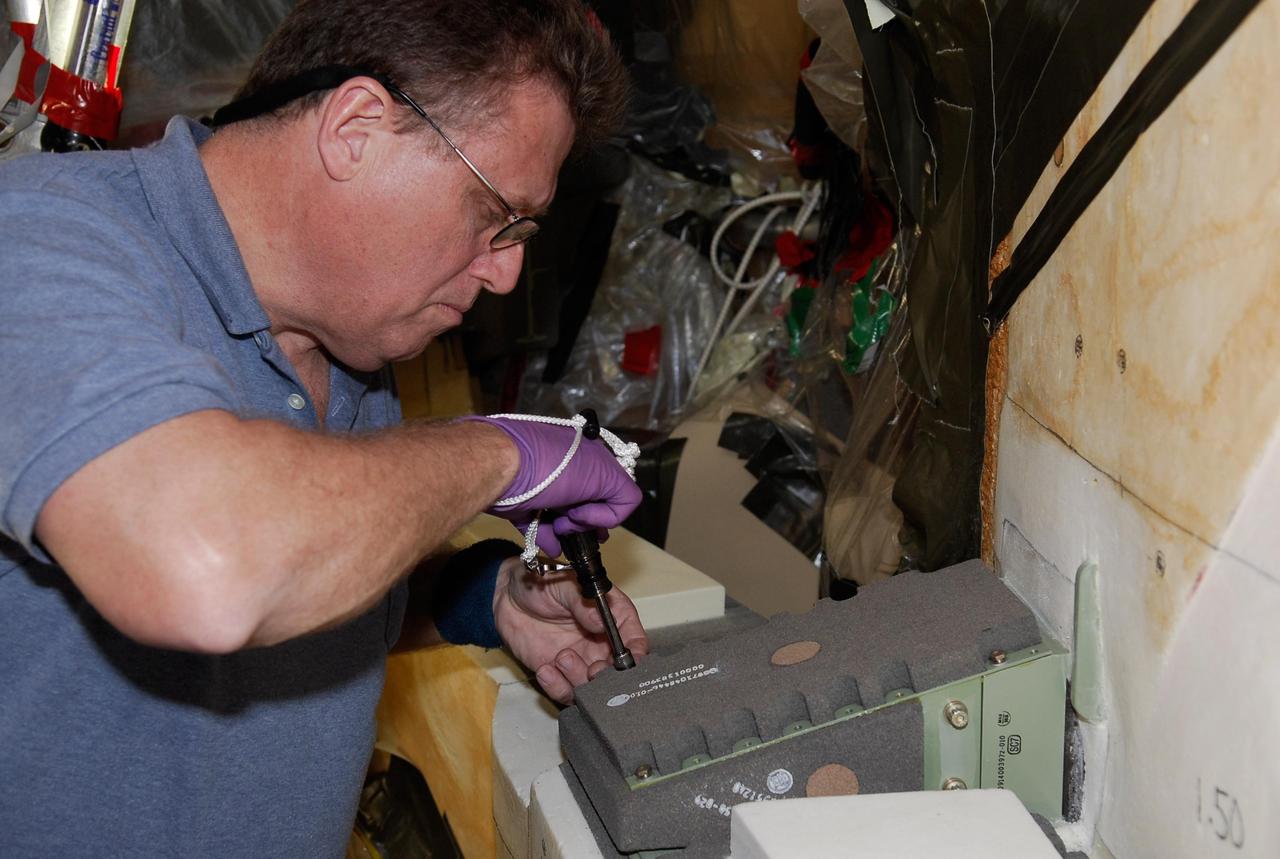
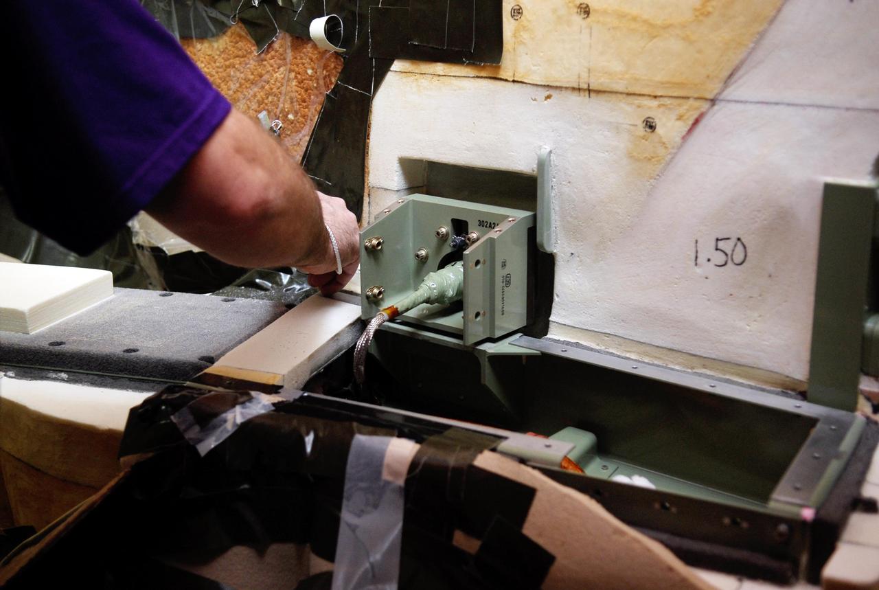
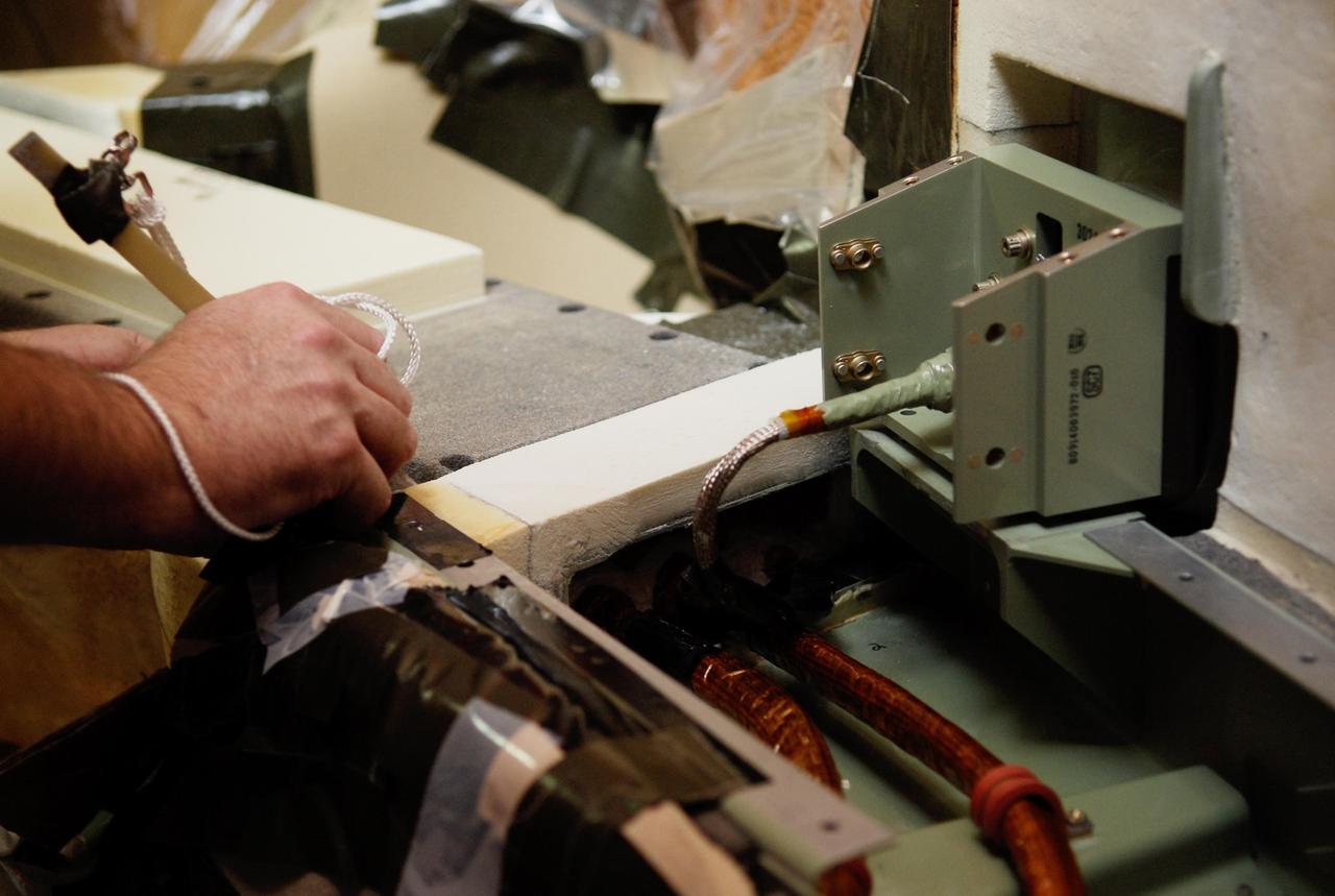
EXPLODING WIRE GUN WITH CAPACITORS
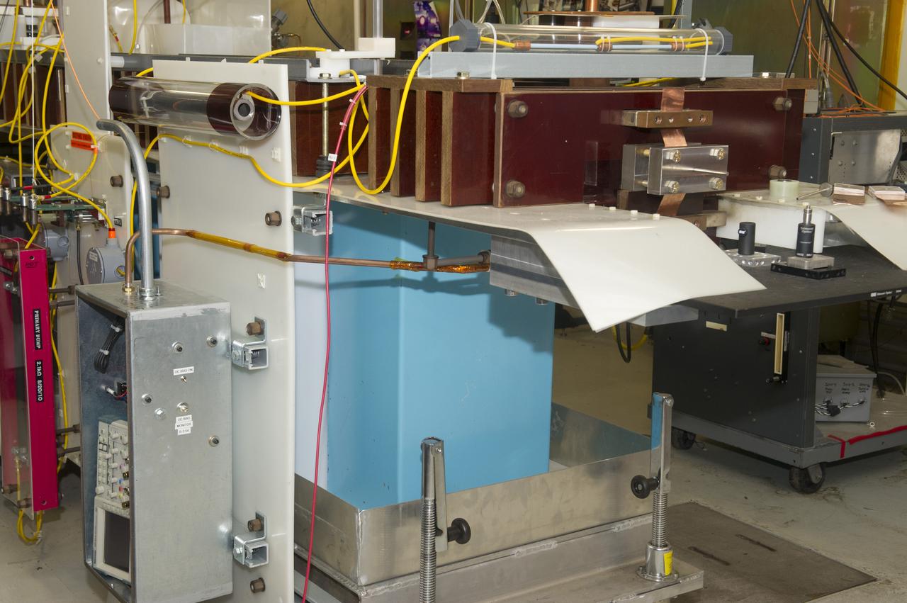
OVERALL VIEW OF EXPLODING WIRE GUN
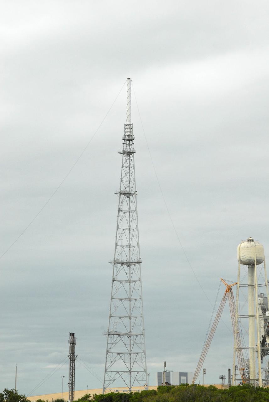
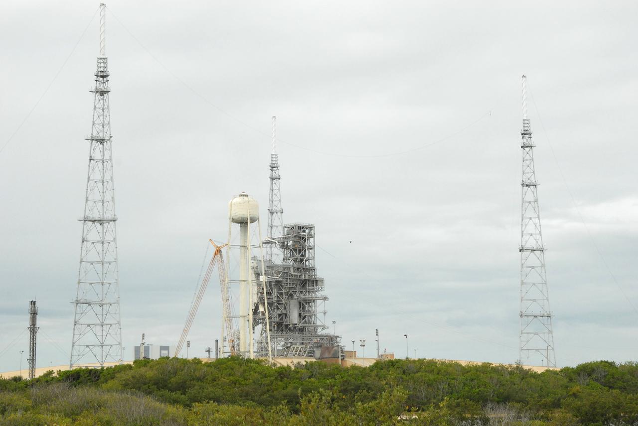
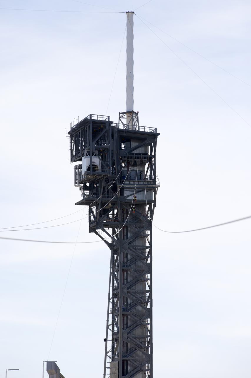
CAPE CANAVERAL, Fla. – On Launch Pad 39B at NASA's Kennedy Space Center in Florida, catenary wires are being suspended from the lighting masts on the lightning towers. The catenary wire system under development for the Constellation Program’s next-generation vehicles will significantly increase the shielding level, providing better protection, and further separate the electrical current from vital launch hardware. The system will help avoid delays to the launch schedule by collecting more information on the strike for analysis by launch managers. Photo credit: NASA/Jack Pfaller
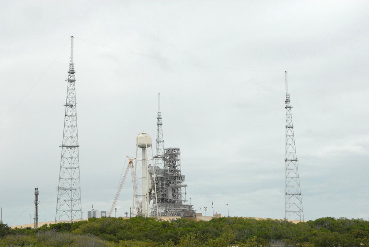
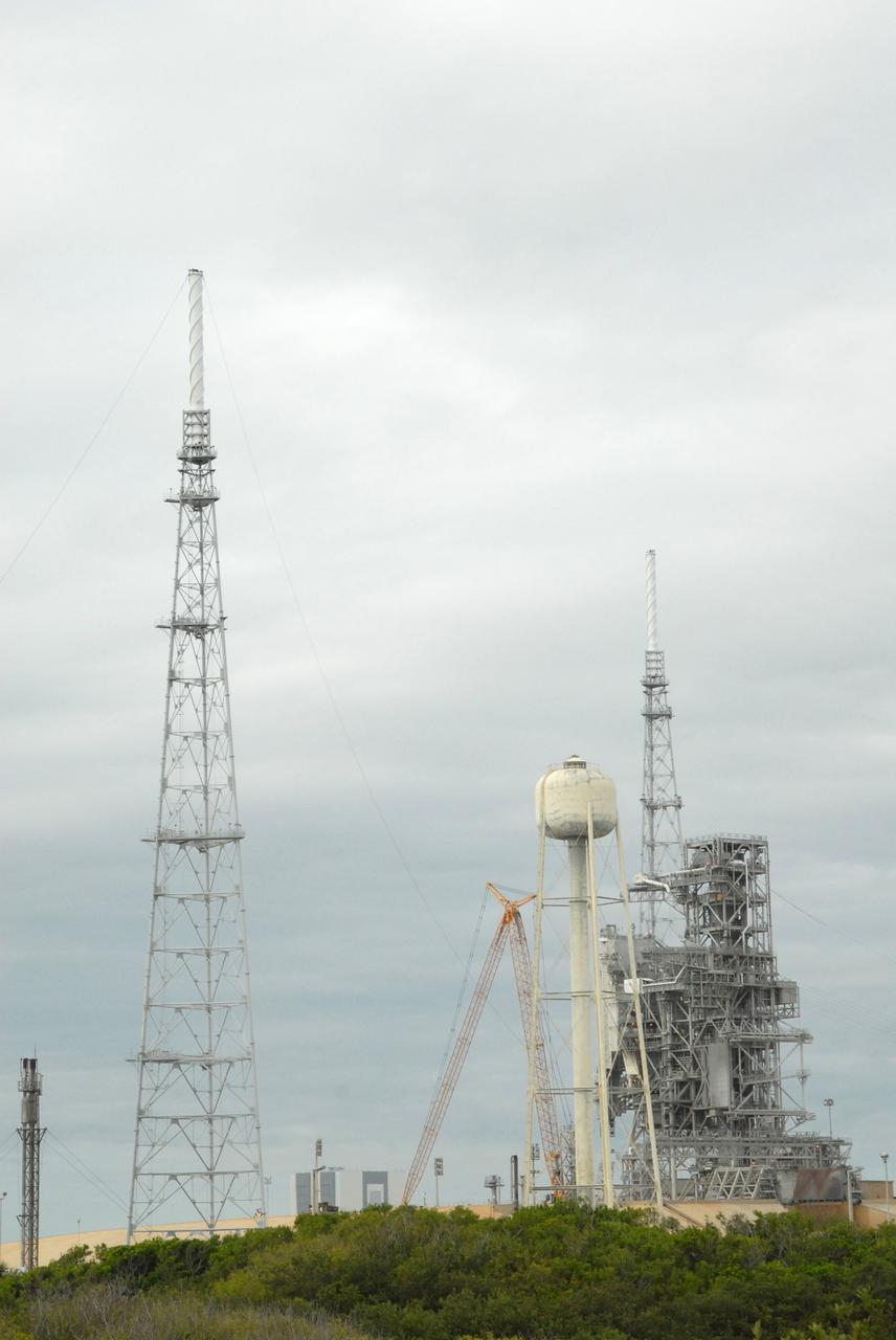
CAPE CANAVERAL, Fla. – On Launch Pad 39B at NASA's Kennedy Space Center in Florida, catenary wires are being suspended from the lighting masts on the lightning towers. The catenary wire system under development for the Constellation Program’s next-generation vehicles will significantly increase the shielding level, providing better protection, and further separate the electrical current from vital launch hardware. The system will help avoid delays to the launch schedule by collecting more information on the strike for analysis by launch managers. Photo credit: NASA/Jack Pfaller
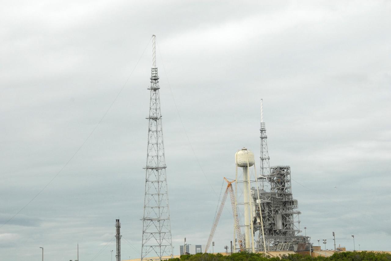
CAPE CANAVERAL, Fla. – On Launch Pad 39B at NASA's Kennedy Space Center in Florida, catenary wires are being suspended from the lighting masts on the lightning towers. The catenary wire system under development for the Constellation Program’s next-generation vehicles will significantly increase the shielding level, providing better protection, and further separate the electrical current from vital launch hardware. The system will help avoid delays to the launch schedule by collecting more information on the strike for analysis by launch managers. Photo credit: NASA/Jack Pfaller
CAPE CANAVERAL, Fla. – On Launch Pad 39B at NASA's Kennedy Space Center in Florida, catenary wires are being suspended from the lighting masts on the lightning towers. The catenary wire system under development for the Constellation Program’s next-generation vehicles will significantly increase the shielding level, providing better protection, and further separate the electrical current from vital launch hardware. The system will help avoid delays to the launch schedule by collecting more information on the strike for analysis by launch managers. Photo credit: NASA/Jack Pfaller
CAPE CANAVERAL, Fla. – On Launch Pad 39B at NASA's Kennedy Space Center in Florida, catenary wires are being suspended from the lighting masts on the lightning towers. The catenary wire system under development for the Constellation Program’s next-generation vehicles will significantly increase the shielding level, providing better protection, and further separate the electrical current from vital launch hardware. The system will help avoid delays to the launch schedule by collecting more information on the strike for analysis by launch managers. Photo credit: NASA/Jack Pfaller
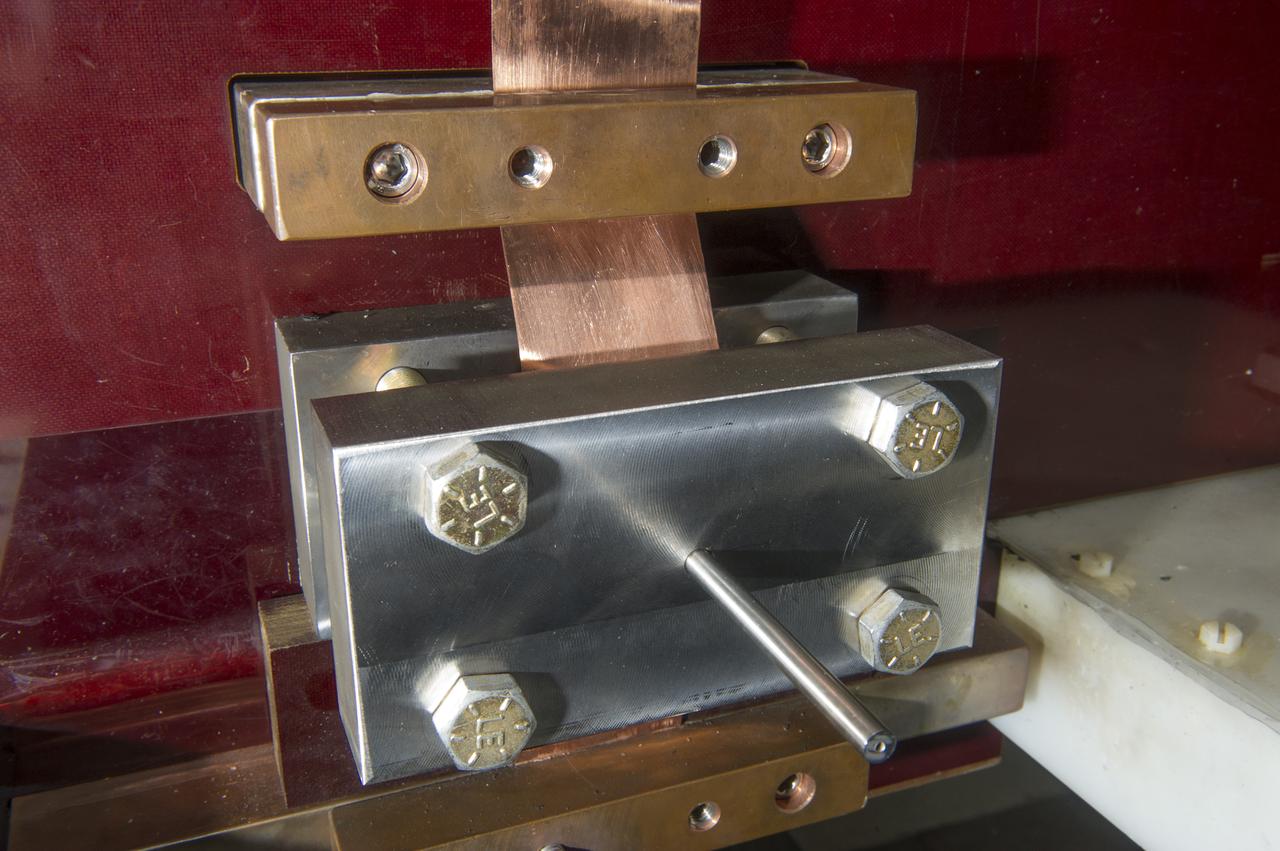
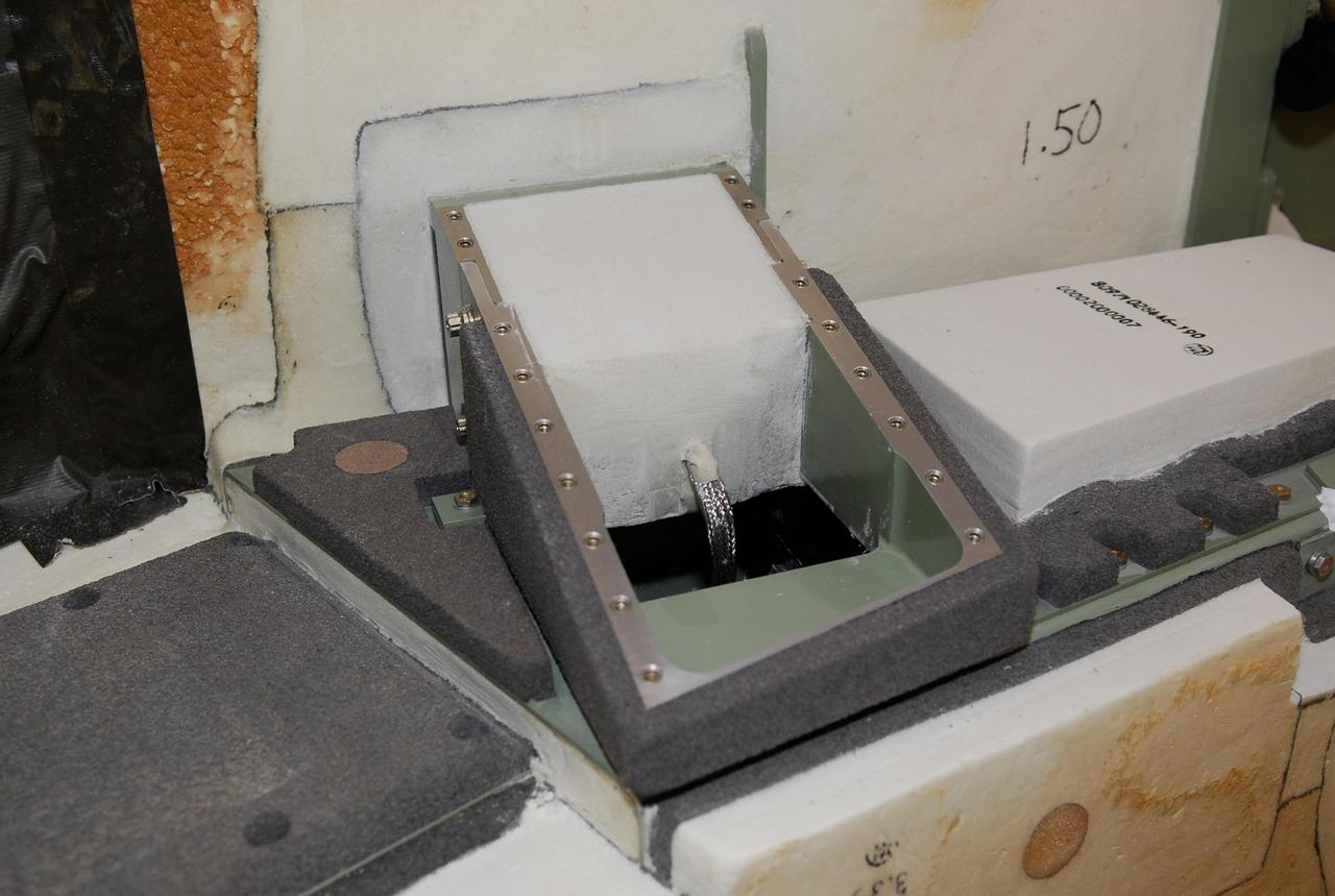
EXPLODING WIRE GUN, BARREL BLOCK ASSEMBLY, BLDG 4205

EXPLODING WIRE GUN, BLDG 4205, WITH BACKING BLOCK, BARREL, COPPER RIBBON WITH WIRE
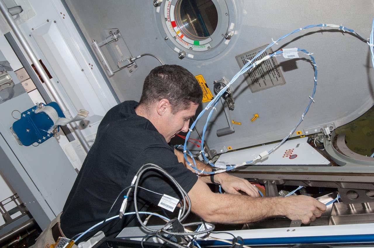
ISS038-E-008291 (24 Nov. 2013) --- NASA astronaut Michael Hopkins, Expedition 38 flight engineer, installs wire harnesses in the International Space Station?s Harmony node to support the installation of Ethernet video cables for the station?s local area network. These new cables will provide Ethernet connectivity to the visiting vehicles that dock to Harmony?s Earth-facing port.
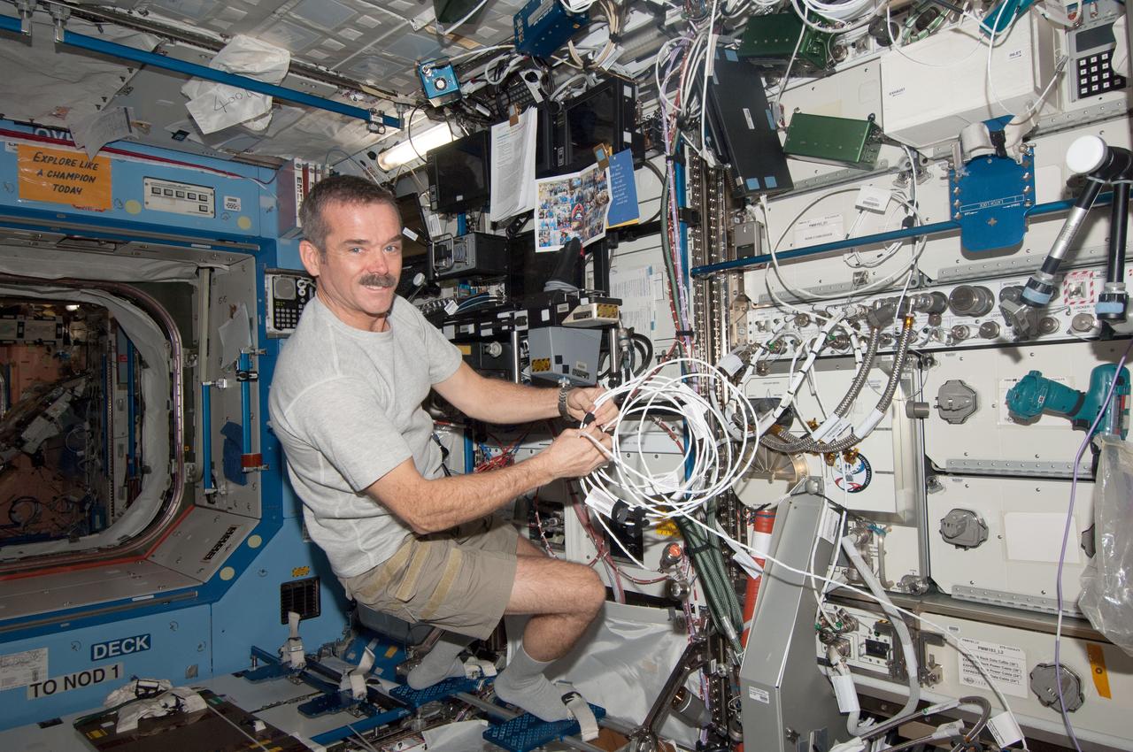
View of Canadian Space Agency (CSA) Chris Hadfield, Expedition 34 Flight Engineer (FE), wiring the condensate transfer pump, in the U.S. Laboratory. Image was released via astronaut Twitter. Original camera number is 268C1459. Photo was taken during Expedition 34.

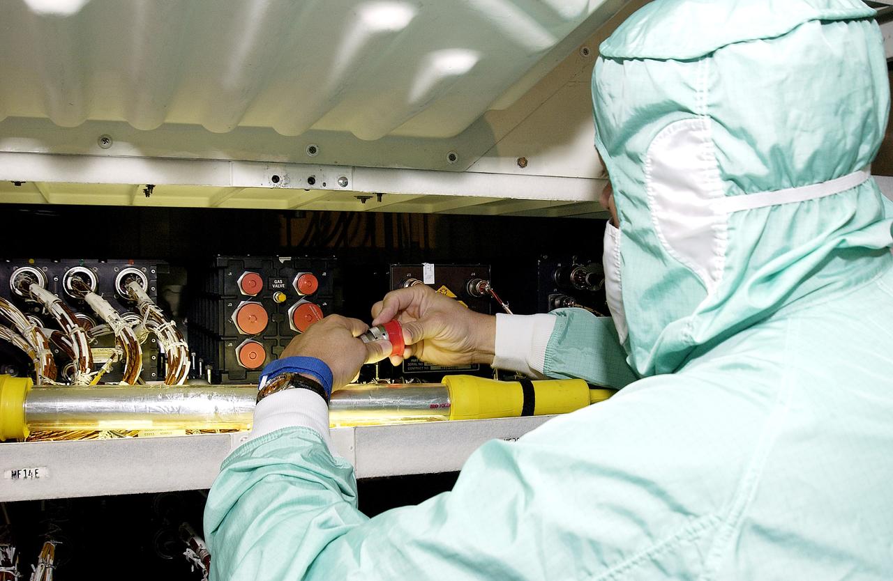
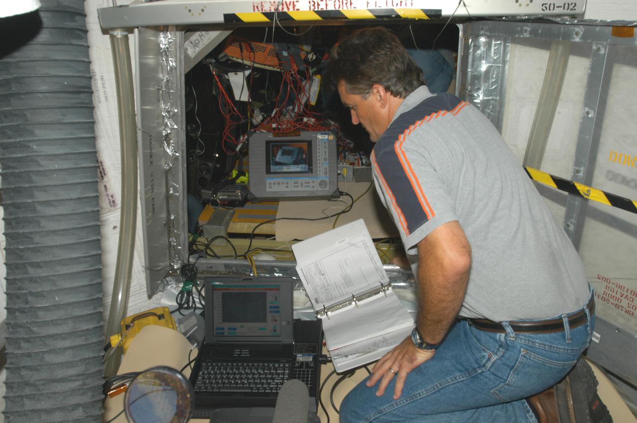
STS078-397-010 (20 June - 7 July 1996) --- Payload specialist Jean-Jacques Favier, representing the French Space Agency (CNES), and astronaut Kevin R. Kregel, pilot, perform a successful Inflight Maintenance (IFM) on the Bubble Drop Particle Unit (BDPU). The IFM technique was performed initially on the ground at the Marshall Space Flight Center (MSFC) by alternate payload specialist Pedro Duque of the European Space Agency (ESA), with the procedure being recorded on video and uplinked to the crew of the Space Shuttle Columbia to aid in the repair.
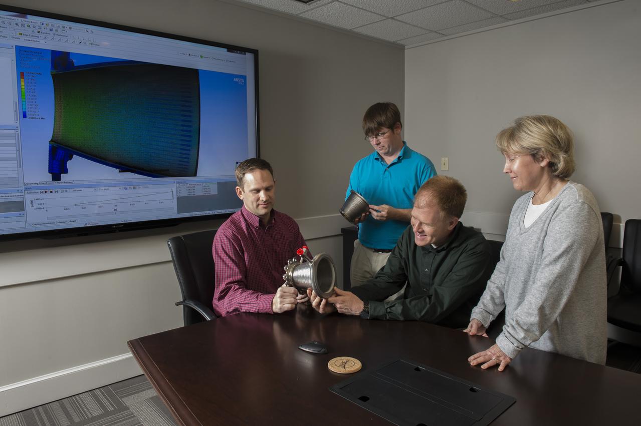
Engineers from NASA Marshall Space Flight Center's Propulsion Department examine nozzles fabricated using a freeform-directed energy wire deposition process. From left are Paul Gradl, Will Brandsmeier, Ian Johnston and Sandy Greene, with the nozzles, which were built using a NASA-patented technology that has the potential to reduce build time from several months to several weeks.
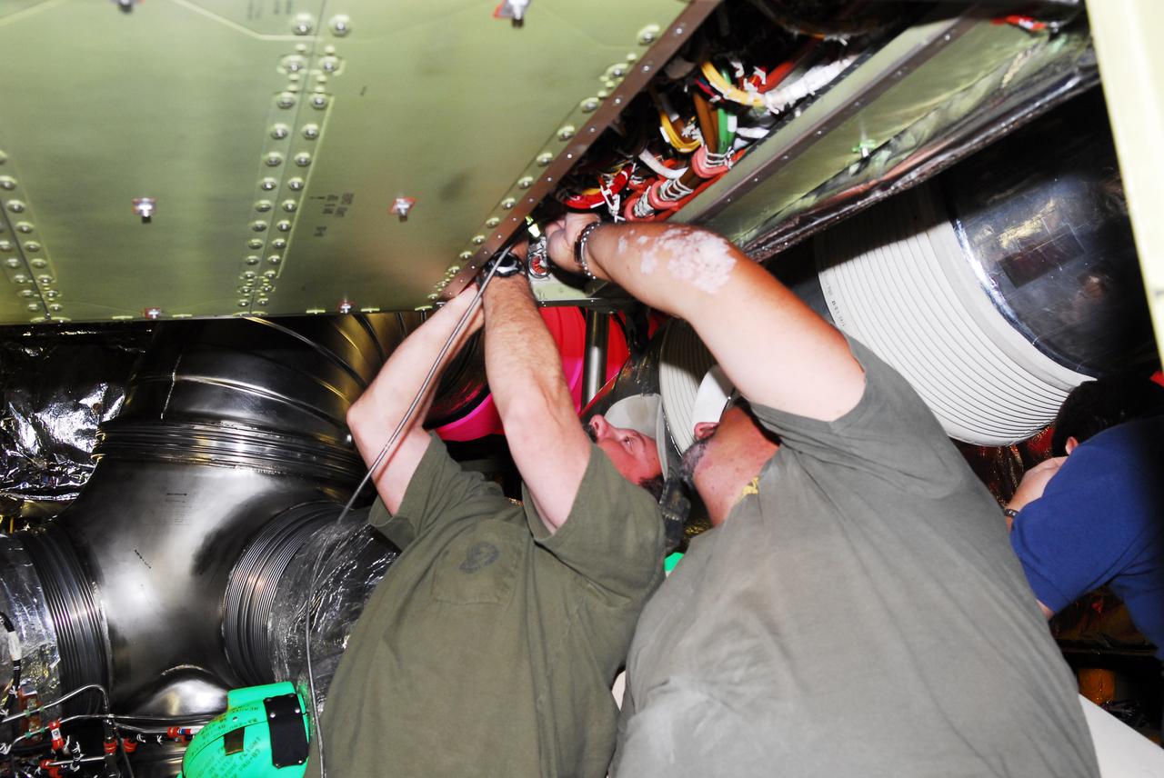
KENNEDY SPACE CENTER, FLA. - A technician with United Space Alliance checks wiring in the mid-body and flight deck of orbiter Atlantis as part of routine maintenance.

KENNEDY SPACE CENTER, FLA. - A technician with United Space Alliance checks wiring in the mid-body of orbiter Atlantis as part of routine maintenance.
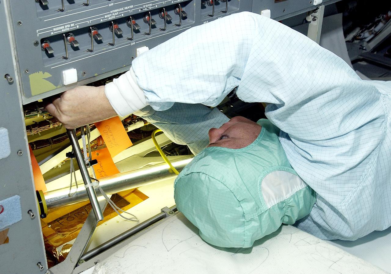
KENNEDY SPACE CENTER, FLA. - A technician with United Space Alliance checks wiring in the mid-body and flight deck of orbiter Atlantis as part of routine maintenance.
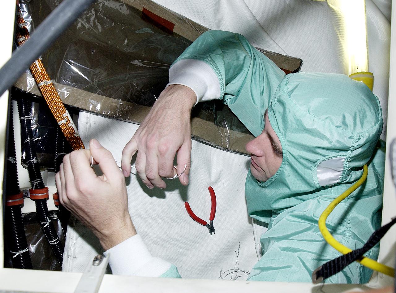
KENNEDY SPACE CENTER, FLA. - A technician with United Space Alliance checks wiring in the mid-body and flight deck of orbiter Atlantis as part of routine maintenance.

This image from NASA Mars Odyssey spacecraft shows a barbed wire-like feature on the surface of Mars.
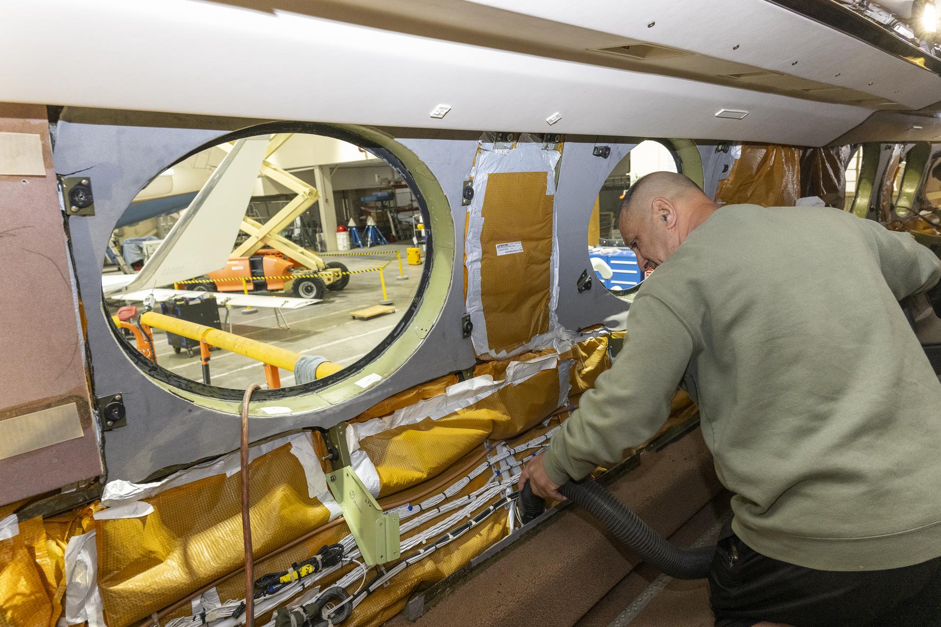
Eric Apikian, an aircraft mechanic, vacuums a NASA Gulfstream G-III aircraft compartment after wiring was added for sensors on Wednesday, Jan. 7, 2026, at NASA’s Armstrong Flight Research Center in Edwards, California. The modifications prepare the aircraft to join three others flying at different altitudes to capture a complete view of the Orion spacecraft’s heat shield during Artemis II reentry. This effort is part of NASA’s Scientifically Calibrated In-Flight Imagery project.
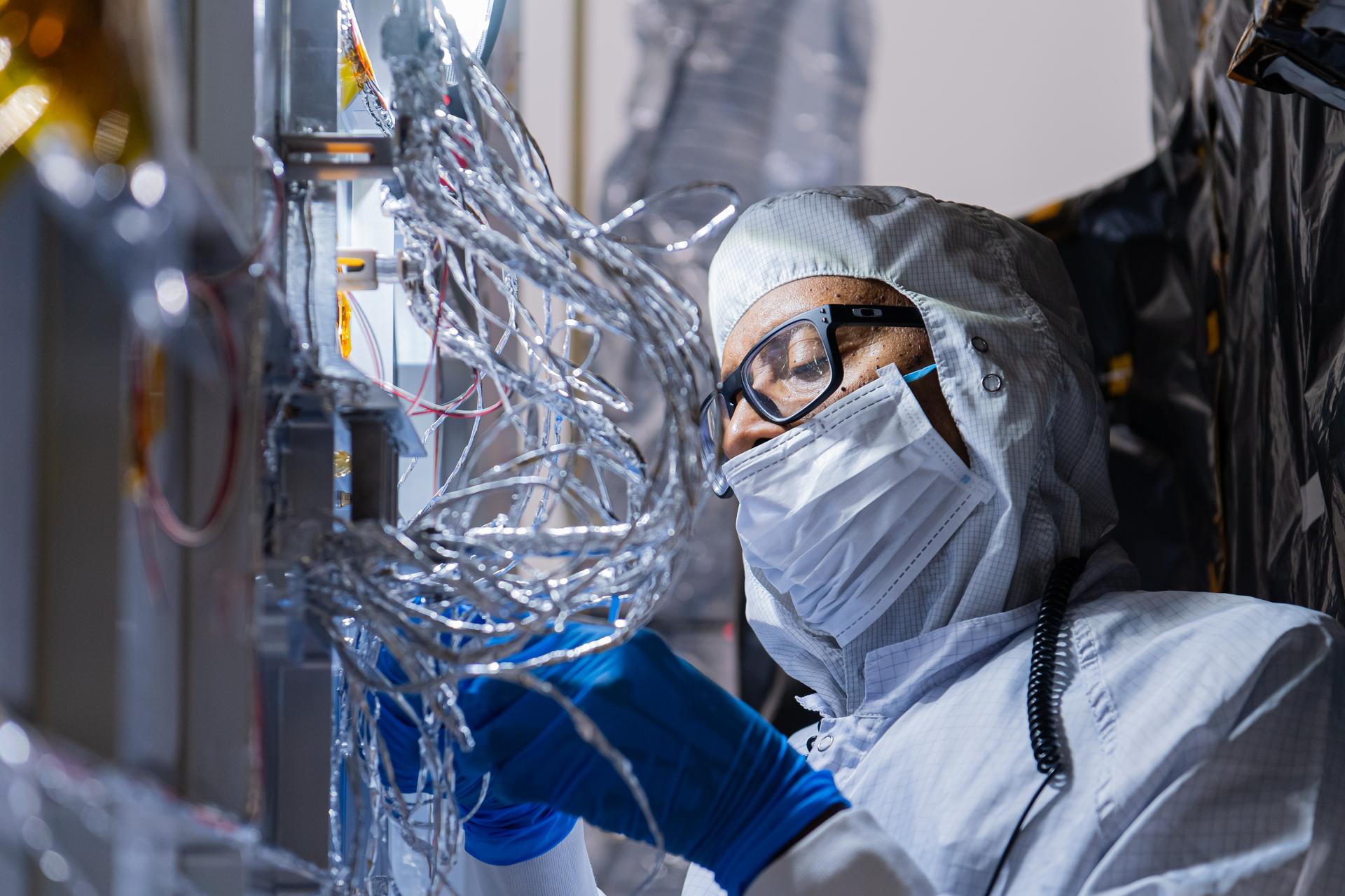
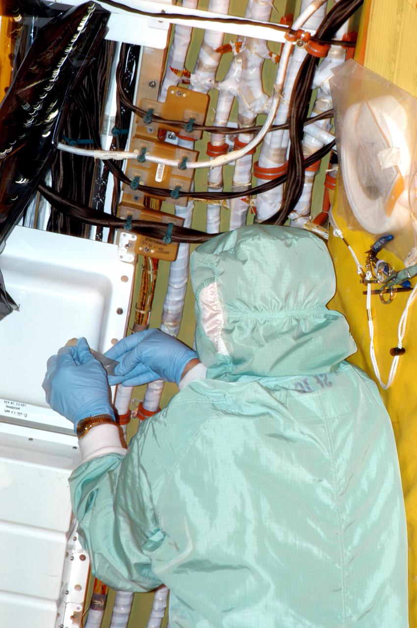
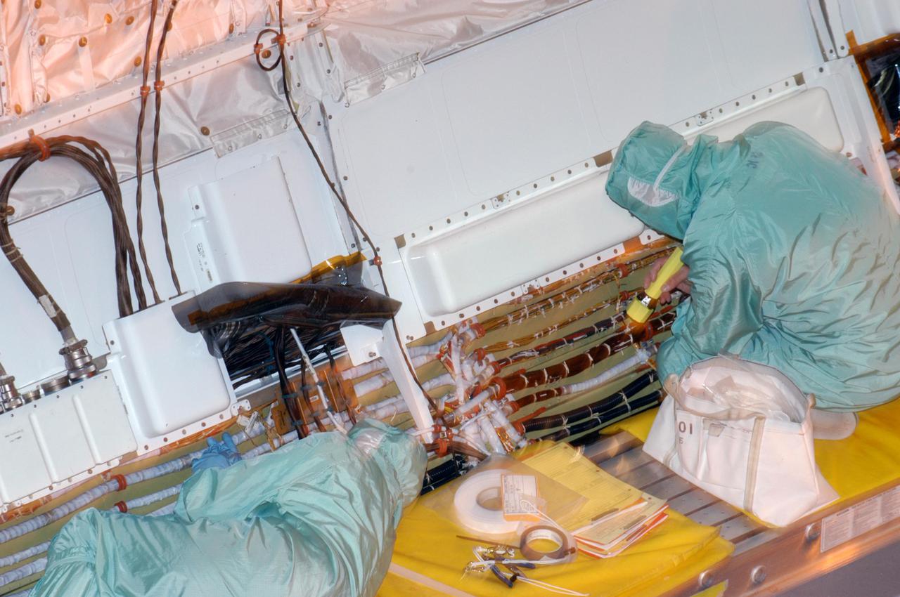
OSAM-1 Electrical Engineer Gregory Griffin tapes hardware on the underside of the OSAM-1 Servicing Payload inside cleanroom at Goddard Space Flight Center, Greenbelt Md., Aug 19, 2024. This photo has been reviewed by the Export Control Office, project Management, and Maxar release authority and is released for public view. NASA/Mike Guinto

KENNEDY SPACE CENTER, FLA. - Technicians with United Space Alliance work in close quarters as they check the wiring on the mid-body of orbiter Atlantis. The inspection is part of routine maintenance.
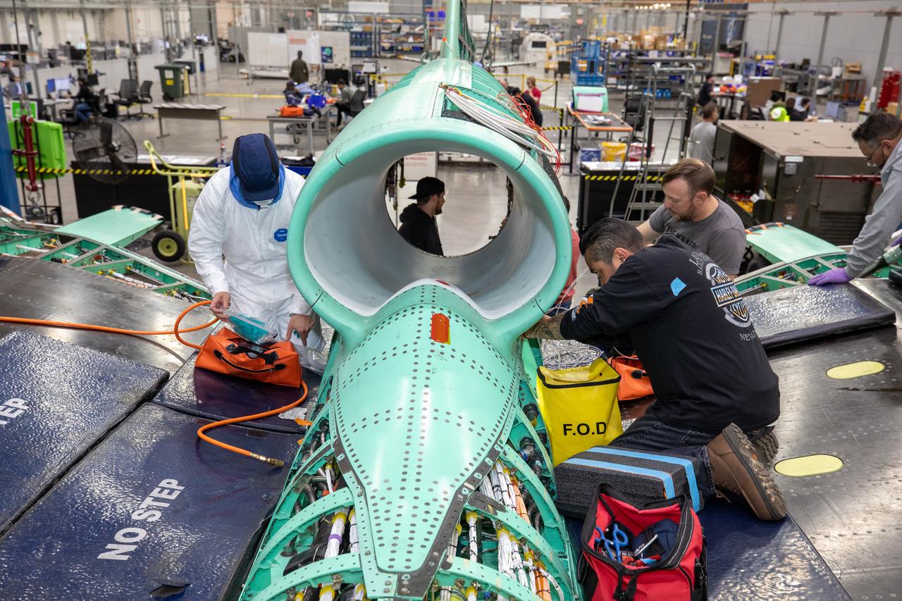
The X-59 team working on the aircraft’s wiring around the engine inlet prior to the engine being installed. Once complete, the X-59 is designed to fly supersonic while reducing the loud sonic boom. The Quesst mission could help change the rules for commercial supersonic air travel over land.
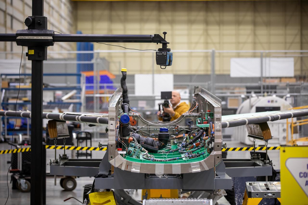
A laser scans the inside of the X-59 aircraft’s lower engine bay at Lockheed Martin Skunk Works in Palmdale, California. These scans can help identify potential hardware or wiring interferences prior to the final installation of the engine and lower tail.
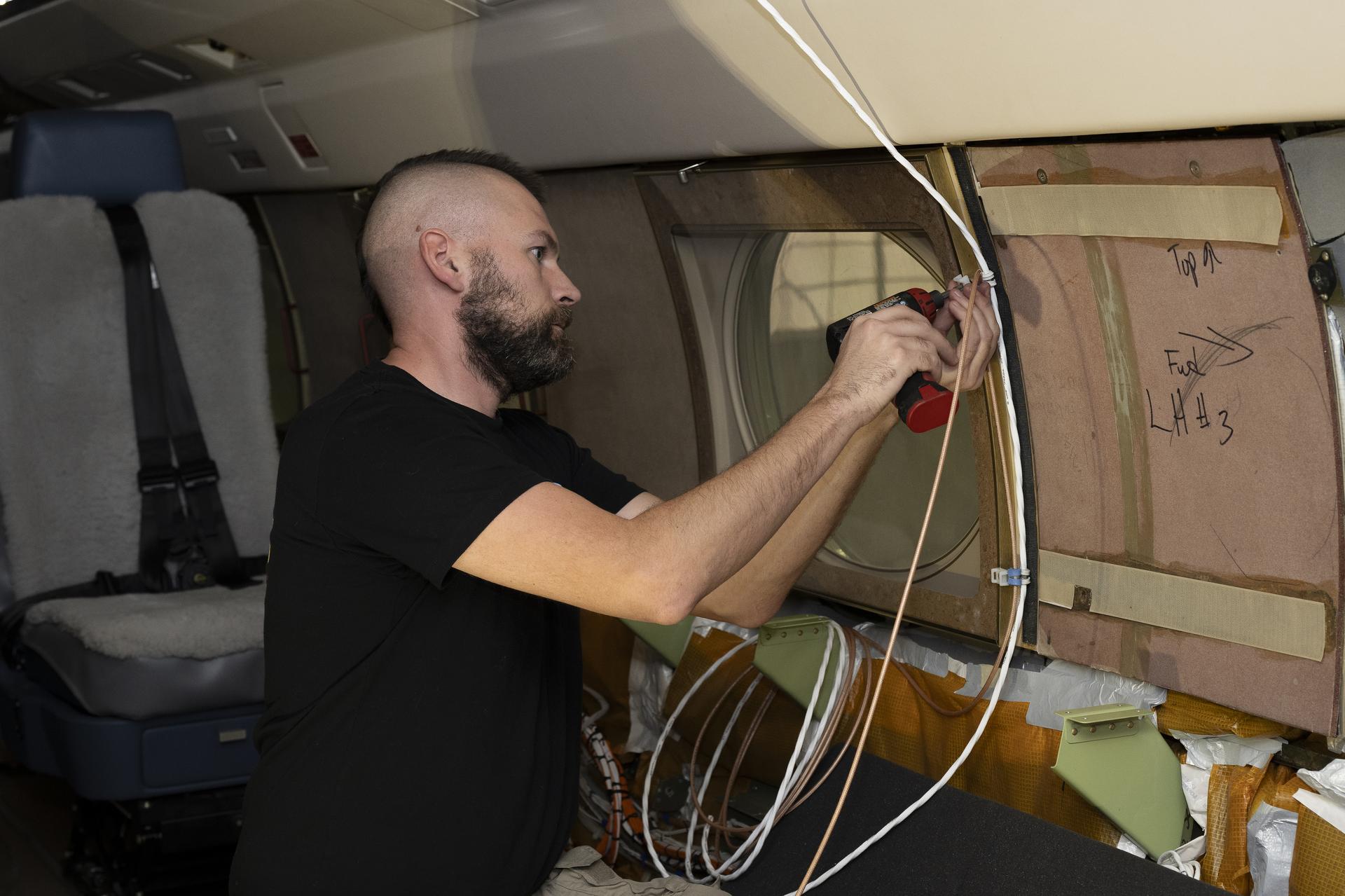
Kelly Jellison, an avionics lead, installs a clip to secure wiring installed on a NASA Gulfstream G-III aircraft on Wednesday, Jan. 7, 2026, at NASA’s Armstrong Flight Research Center in Edwards, California. The modifications prepare the aircraft to join three others flying at different altitudes to capture a complete view of the Orion spacecraft’s heat shield during Artemis II reentry. This effort is part of NASA’s Scientifically Calibrated In-Flight Imagery project.
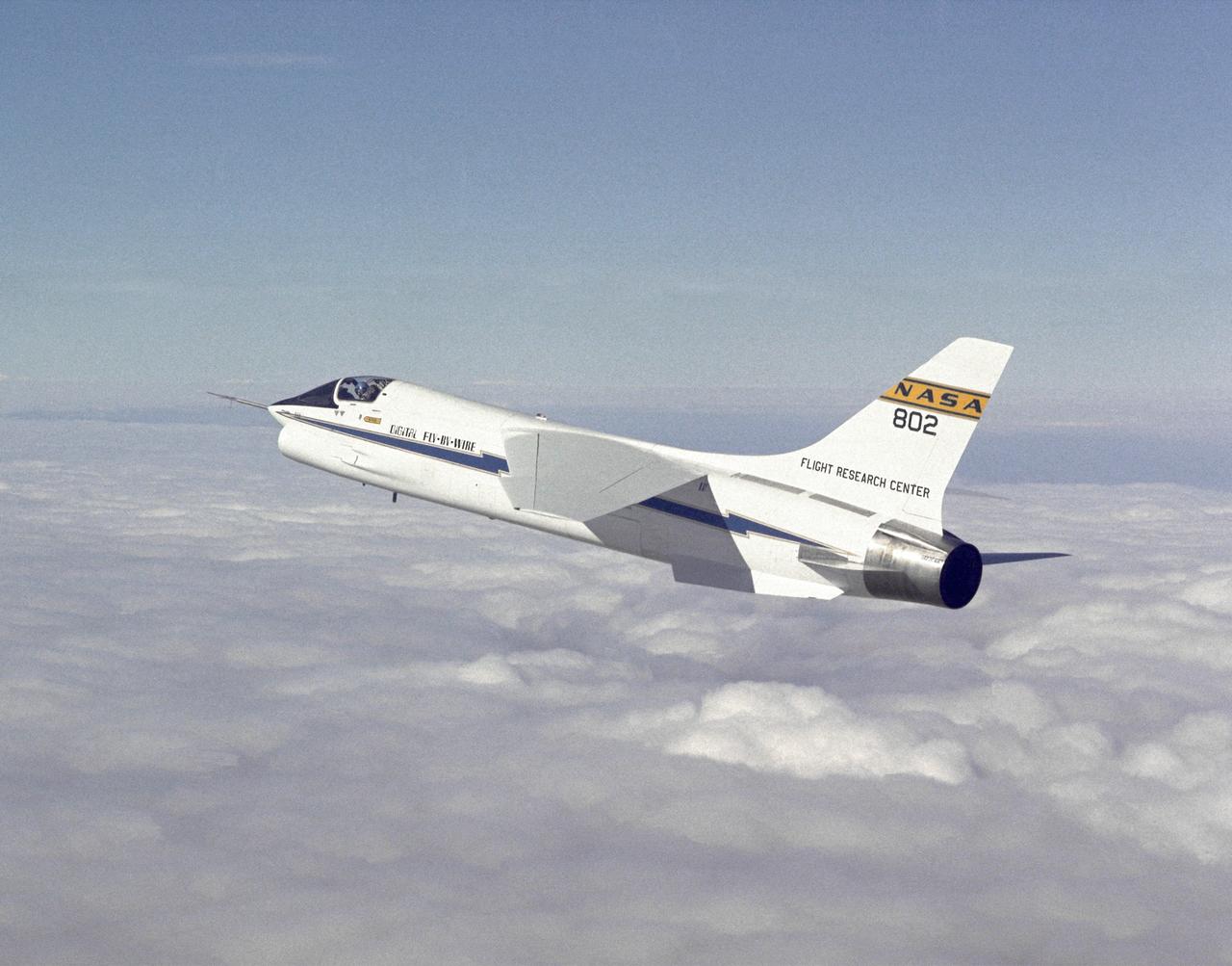
F-8 Digital Fly-By-Wire aircraft in flight. The computer-controlled flight systems pioneered by the F-8 DFBW created a revolution in aircraft design. The F-117A, X-29, X-31, and many other aircraft have relied on computers to make them flyable. Built with inherent instabilities to make them more maneuverable, they would be impossible for human pilots to fly if the computers failed or received incorrect data.
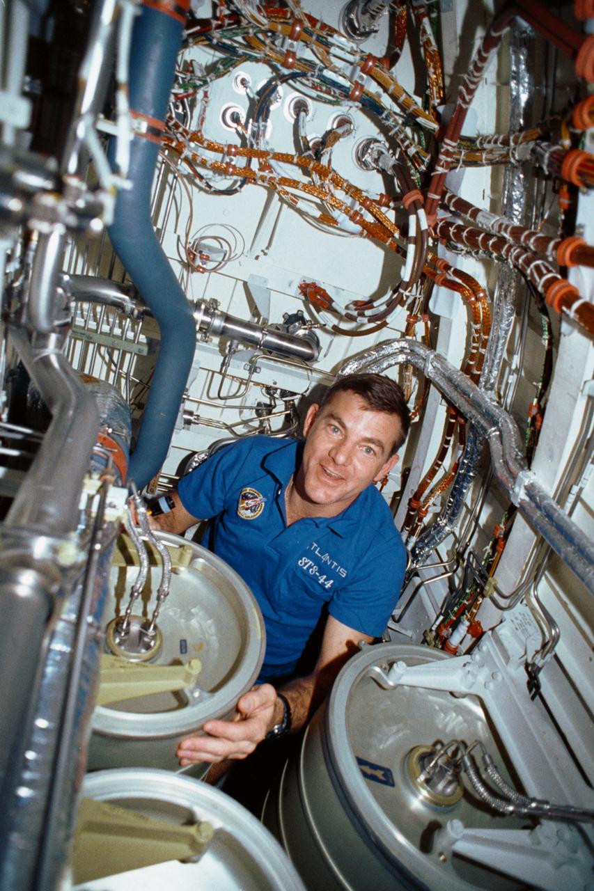
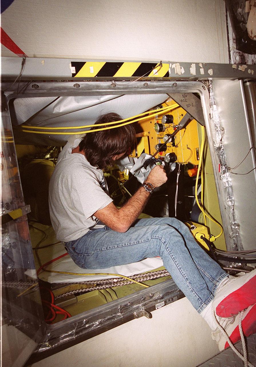
STS-44 Mission Specialist (MS) James S. Voss works under the middeck subfloor of Atlantis, Orbiter Vehicle (OV) 104, to repair humidity separator leakage problems. Voss is surrounded by several water tanks and a maze of shuttle wiring and plumbing. Voss earned the nickname of "Bilge Man" because of his time spent on the lower deck tending to the leakage problem. This is the first photo released of a crewmember in this area of the shuttle.

Shape Memory Alloy - SMA wire Alloy: W6 Size: 0.20mm (as drawn 36% cold work, 0.0079") Manufacture date: 01/08/2009 Quantity: 36mm (120 ft) NiTi 16pt wire Shape Memory Alloy - SMA wire Alloy: W6 Size: 0.20mm (as drawn 36% cold work, 0.0079") Manufacture date: 01/08/2009 Quantity: 36mm (120 ft) NiTi 16pt wire
This image from an animation shows a patch of sandstone scrubbed with the Dust Removal Tool, a wire-bristle brush, on NASA Curiosity Mars rover. This rock target is called Windjana, after a gorge in Western Australia.
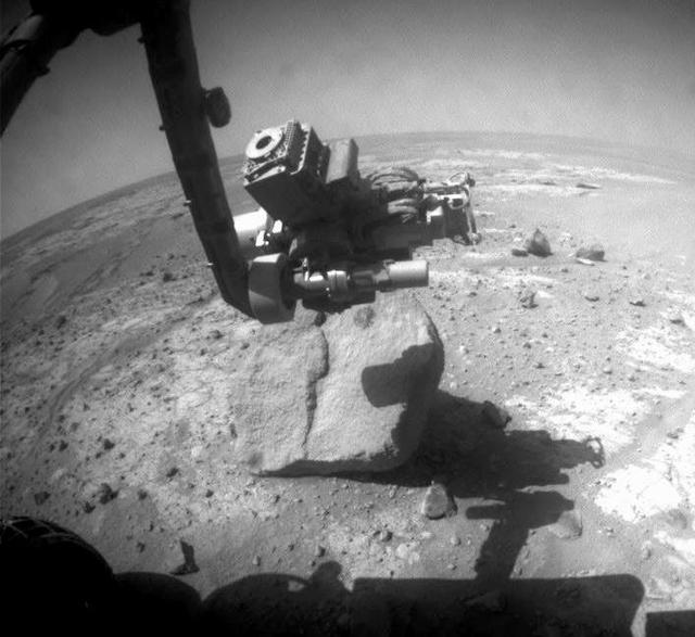
NASA Mars Exploration Rover Opportunity used the wire brush of its rock abrasion tool to scour dust from a circular target area on a rock called Marquette Island.
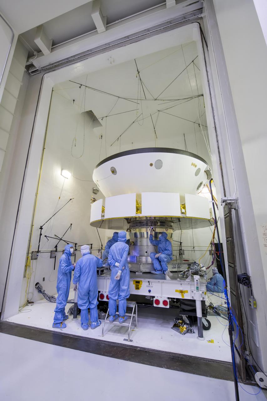
Engineers and technicians working on NASA's Mars 2020 mission prepare spacecraft components for acoustic testing in the Environmental Test Facility at NASA's Jet Propulsion Laboratory in Pasadena, California. The spacecraft is being tested in the same configuration it will be in when sitting atop the Atlas rocket that will launch the latest rover towards Mars in July 2020. The image was taken on April 11, 2019, at JPL. https://photojournal.jpl.nasa.gov/catalog/PIA23160
STS-134 Techs Look at Wire Connectors with Borescope

STS-134 Techs Look at Wire Connectors with Borescope
STS-134 Techs Look at Wire Connectors with Borescope

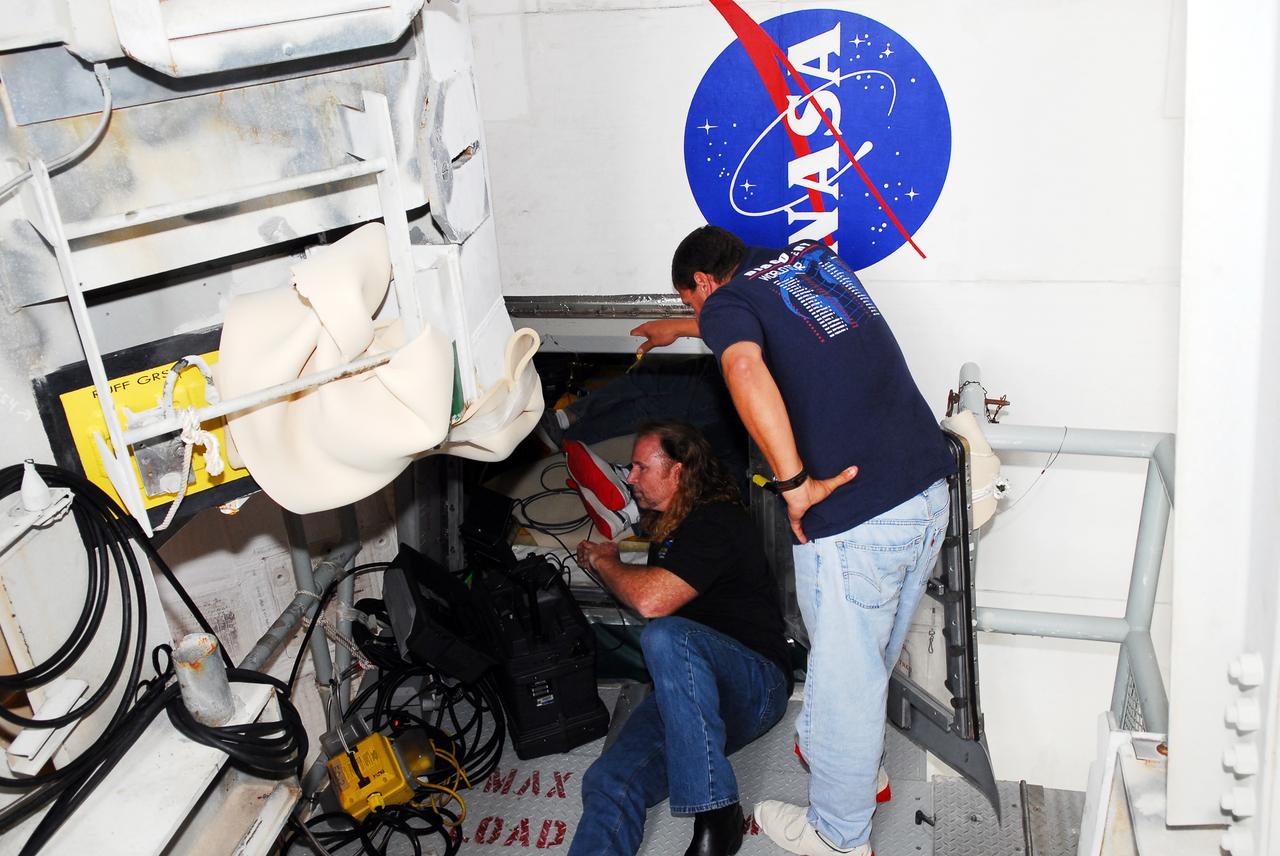
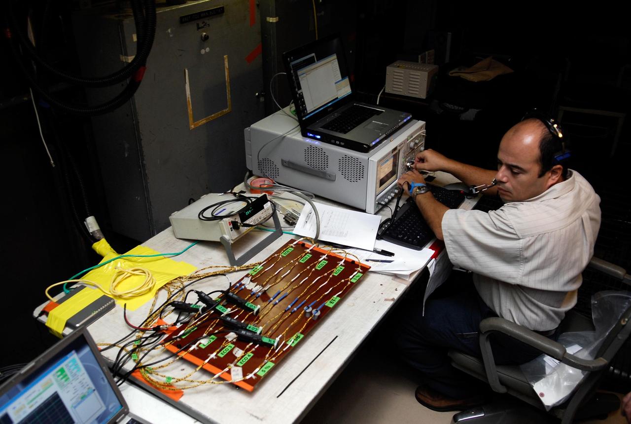
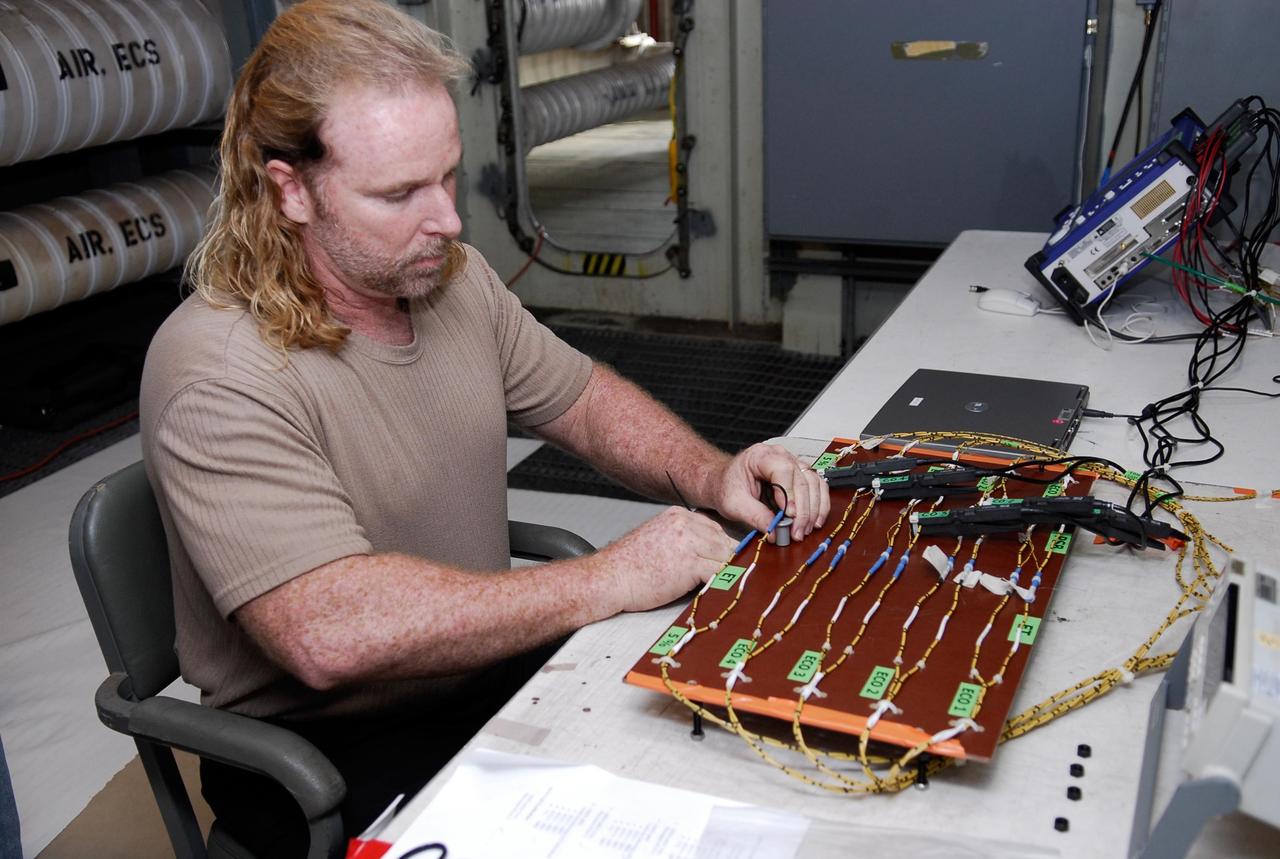
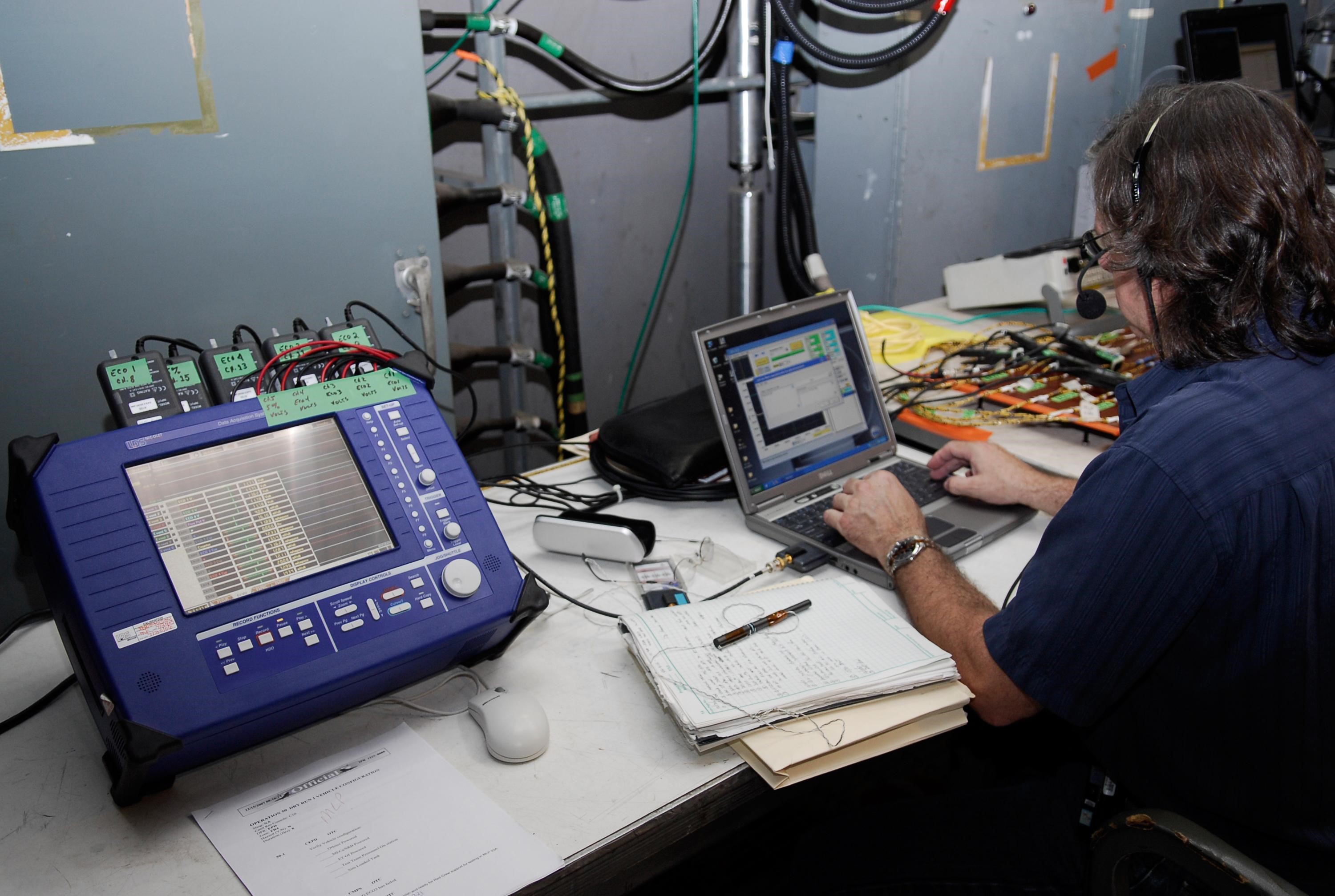
KENNEDY SPACE CENTER, FLA. -- On Launch Pad 39A at NASA's Kennedy Space Center, the wiring is checked and validated before the tanking test on space shuttle Atlantis' external tank set for Dec. 18. The test wiring has been spliced into an electrical harness in the aft main engine compartment connected with the engine cut-off, or ECO, sensor system. The attached wiring leads to the interior of the mobile launcher platform where the time domain reflectometry, or TDR, test equipment is located. Photo credit: NASA/Kim Shiflett
KENNEDY SPACE CENTER, FLA. -- On Launch Pad 39A at NASA's Kennedy Space Center, the wiring is checked and validated before the tanking test on space shuttle Atlantis' external tank set for Dec. 18. The test wiring has been spliced into an electrical harness in the aft main engine compartment connected with the engine cut-off, or ECO, sensor system. The attached wiring leads to the interior of the mobile launcher platform where the time domain reflectometry, or TDR, test equipment is located. Photo credit: NASA/Kim Shiflett
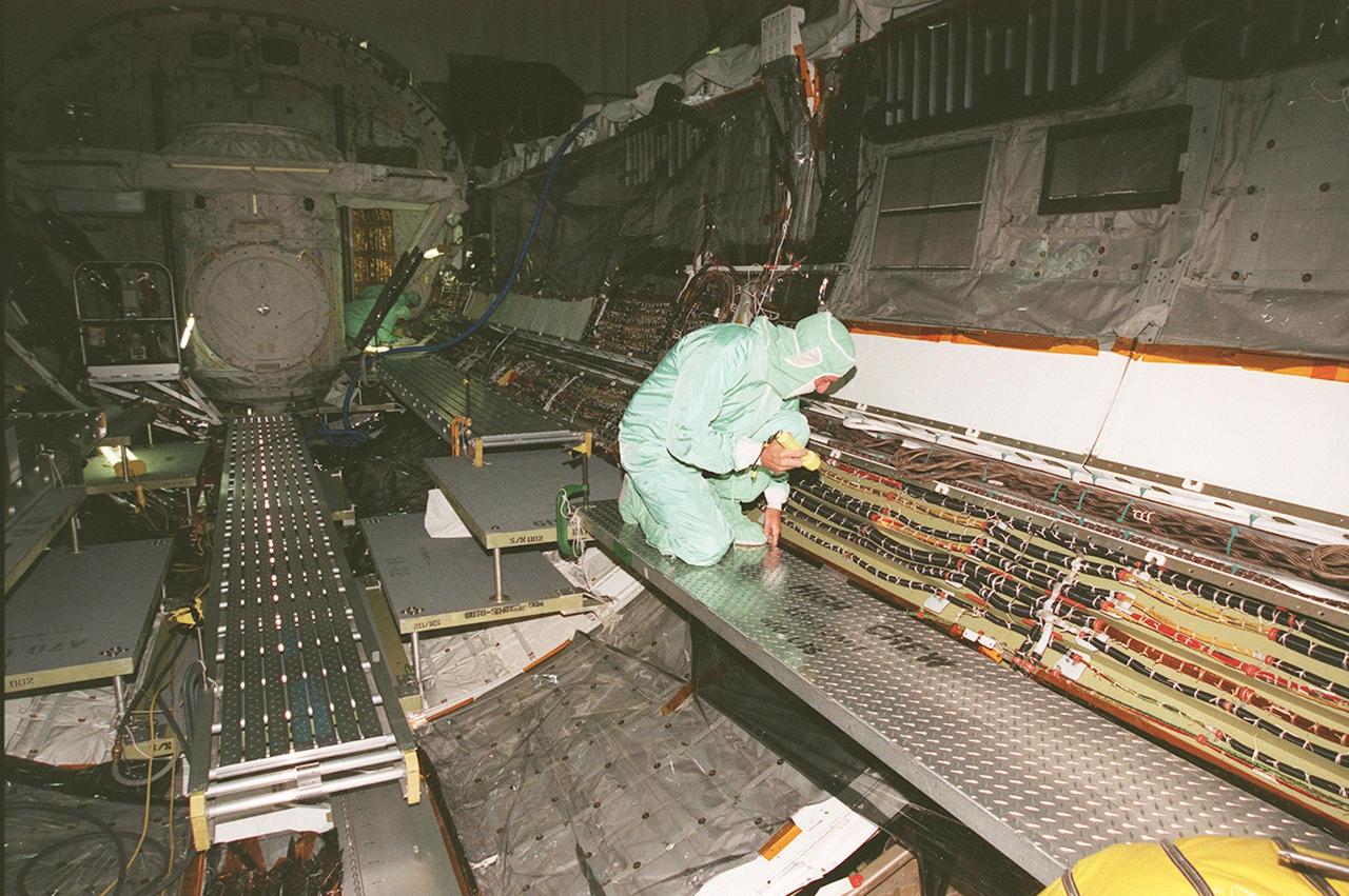
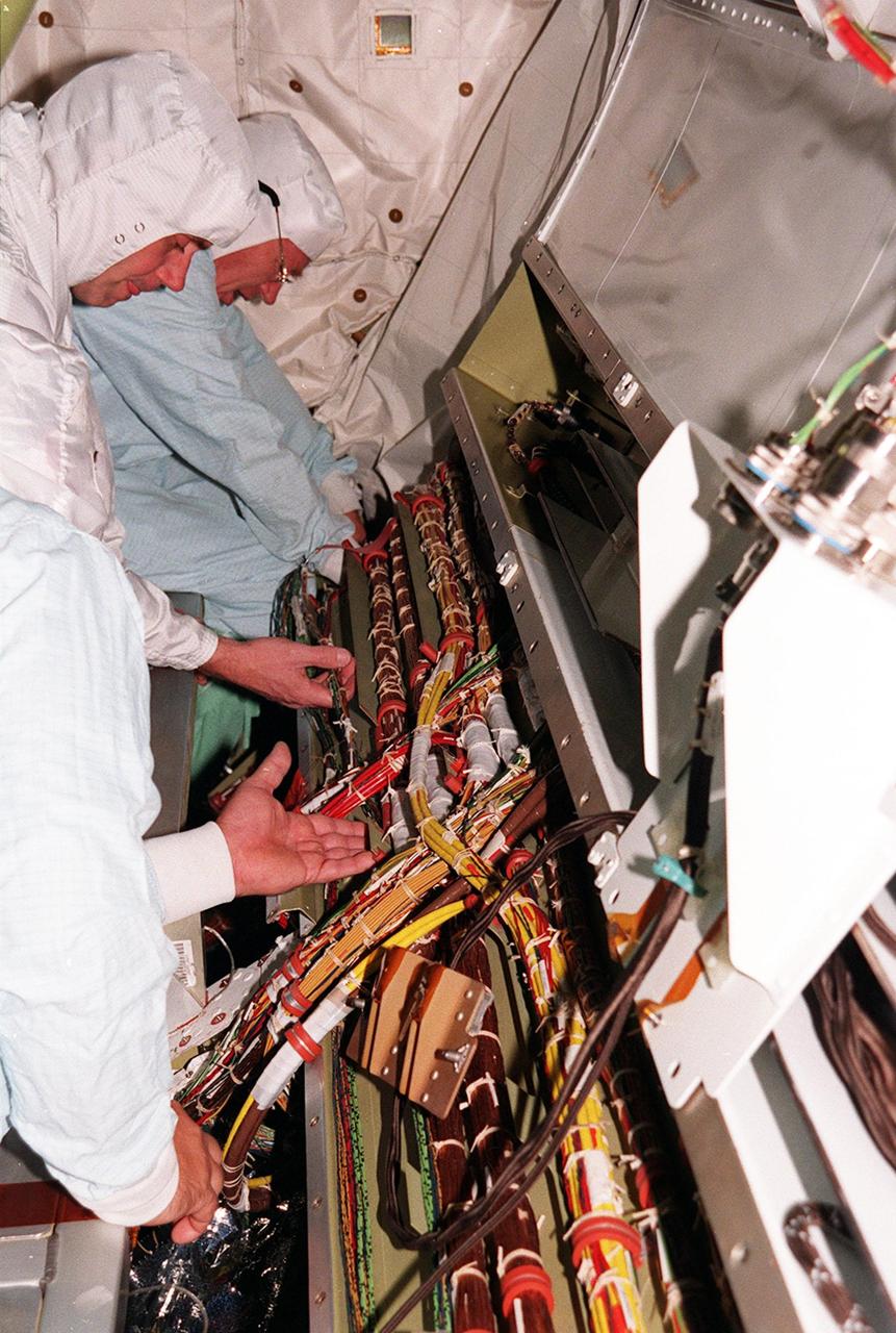
A short during liftoff of Space Shuttle Columbia in July was traced to a wire in the payload bay with damaged insulation. As a result of that problem, NASA decided to inspect much of the wiring in all four Space Shuttles and make repairs as required. Here technicians are examining, repairing and protecting the wires onboard orbiter Endeavour as necessary. The next Shuttle mission, STS-103, the Third Hubble Space Telescope Servicing Mission, is currently scheduled for launch no earlier than Nov. 19, 1999
KENNEDY SPACE CENTER, FLA. -- On Launch Pad 39A at NASA's Kennedy Space Center, the wiring is checked and validated before the tanking test on space shuttle Atlantis' external tank set for Dec. 18. The test wiring has been spliced into an electrical harness in the aft main engine compartment connected with the engine cut-off, or ECO, sensor system. The attached wiring leads to the interior of the mobile launcher platform where the time domain reflectometry, or TDR, test equipment is located. Photo credit: NASA/Kim Shiflett
KENNEDY SPACE CENTER, FLA. -- On Launch Pad 39A at NASA's Kennedy Space Center, the wiring is checked and validated before the tanking test on space shuttle Atlantis' external tank set for Dec. 18. The test wiring has been spliced into an electrical harness in the aft main engine compartment connected with the engine cut-off, or ECO, sensor system. The attached wiring leads to the interior of the mobile launcher platform where the time domain reflectometry, or TDR, test equipment is located. Photo credit: NASA/Kim Shiflett
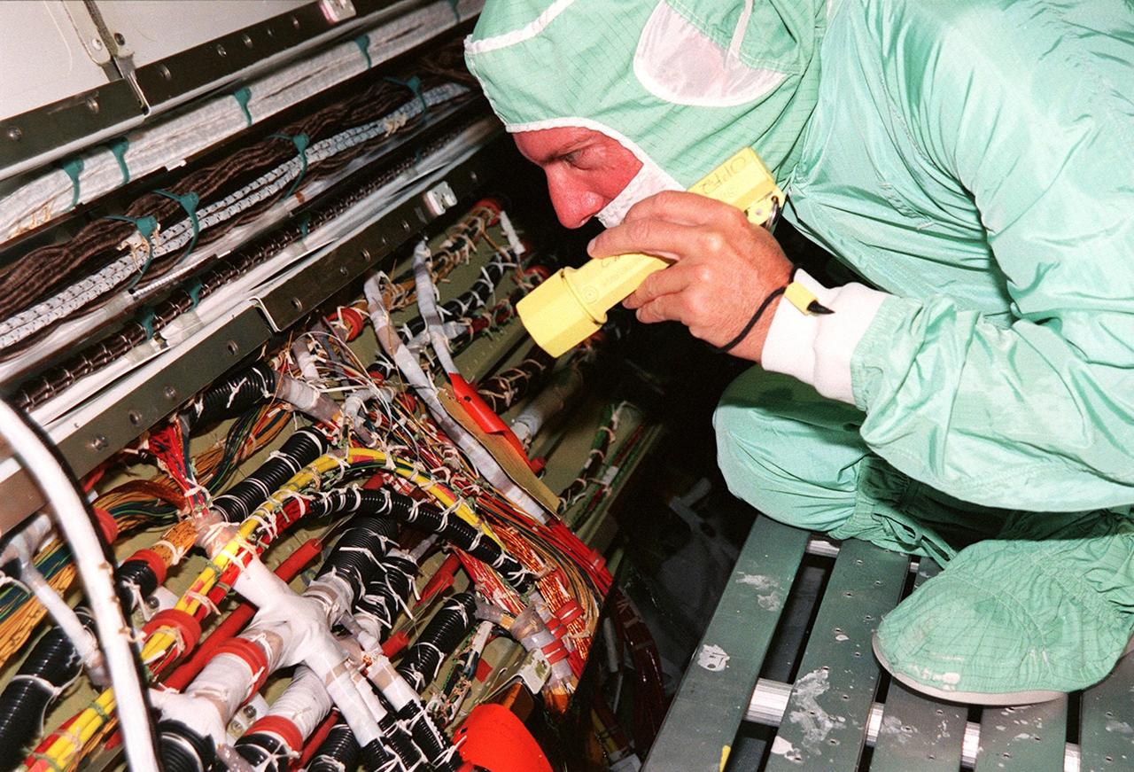
A short during liftoff of Space Shuttle Columbia in July was traced to a wire in the payload bay with damaged insulation. As a result of that problem, NASA decided to inspect much of the wiring in all four Space Shuttles and make repairs as required. Here a technician is examining the wires onboard orbiter Endeavour. The next Shuttle mission, STS-103, the Third Hubble Space Telescope Servicing Mission, is currently scheduled for launch no earlier than Nov. 19, 1999
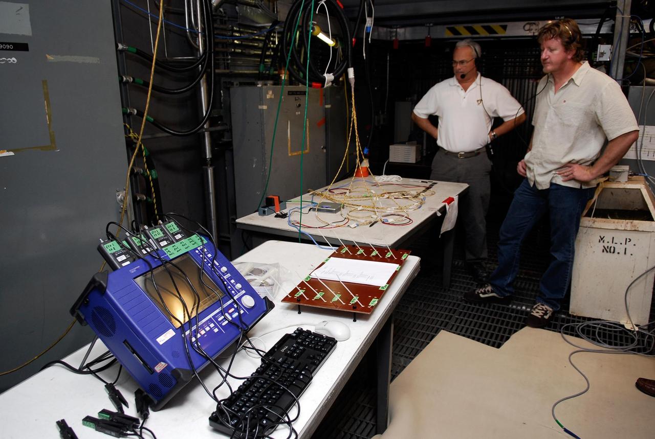
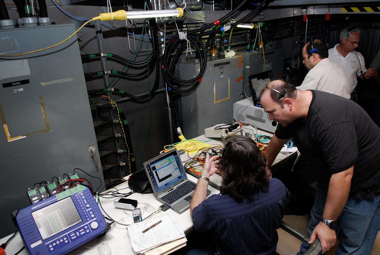
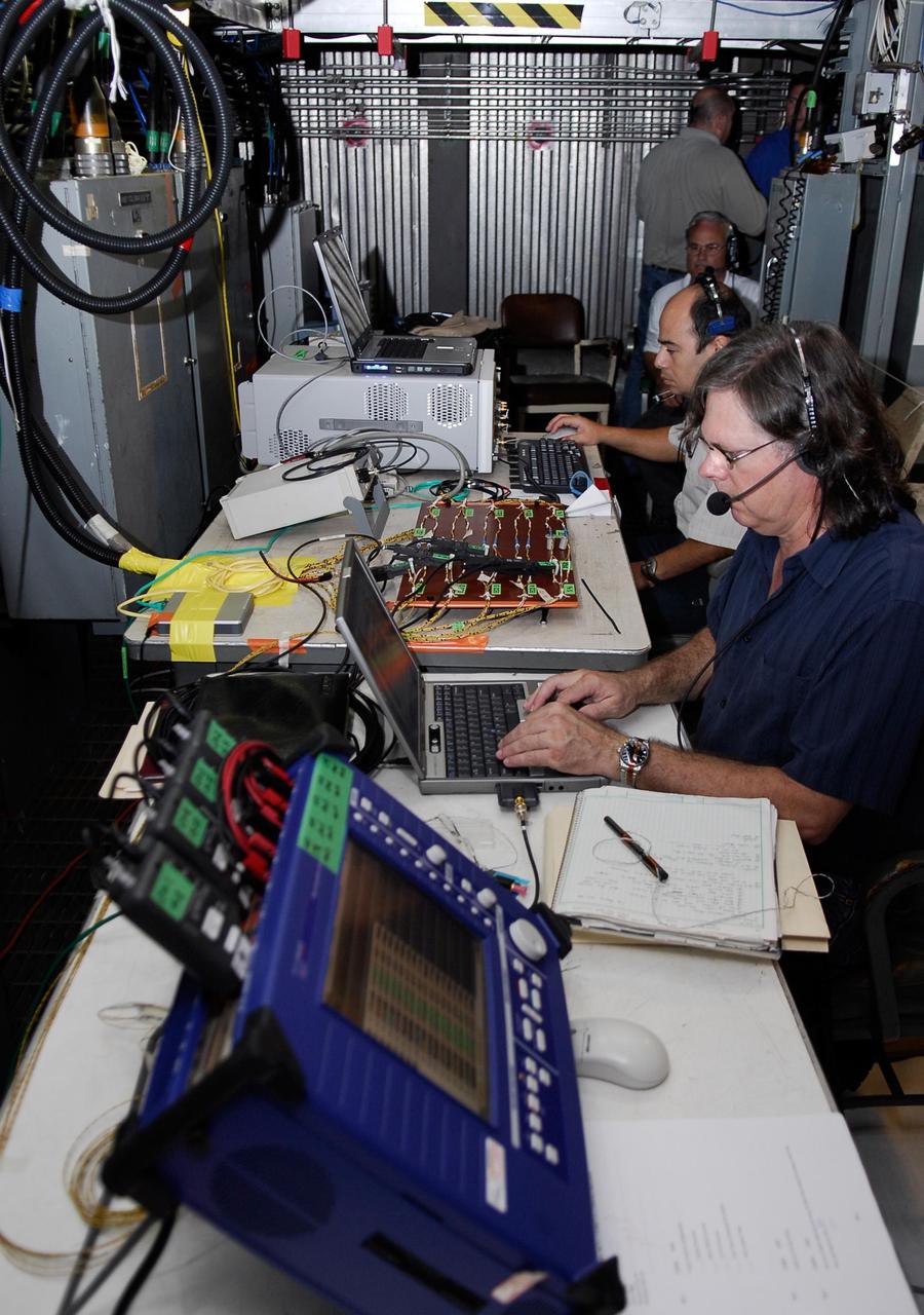
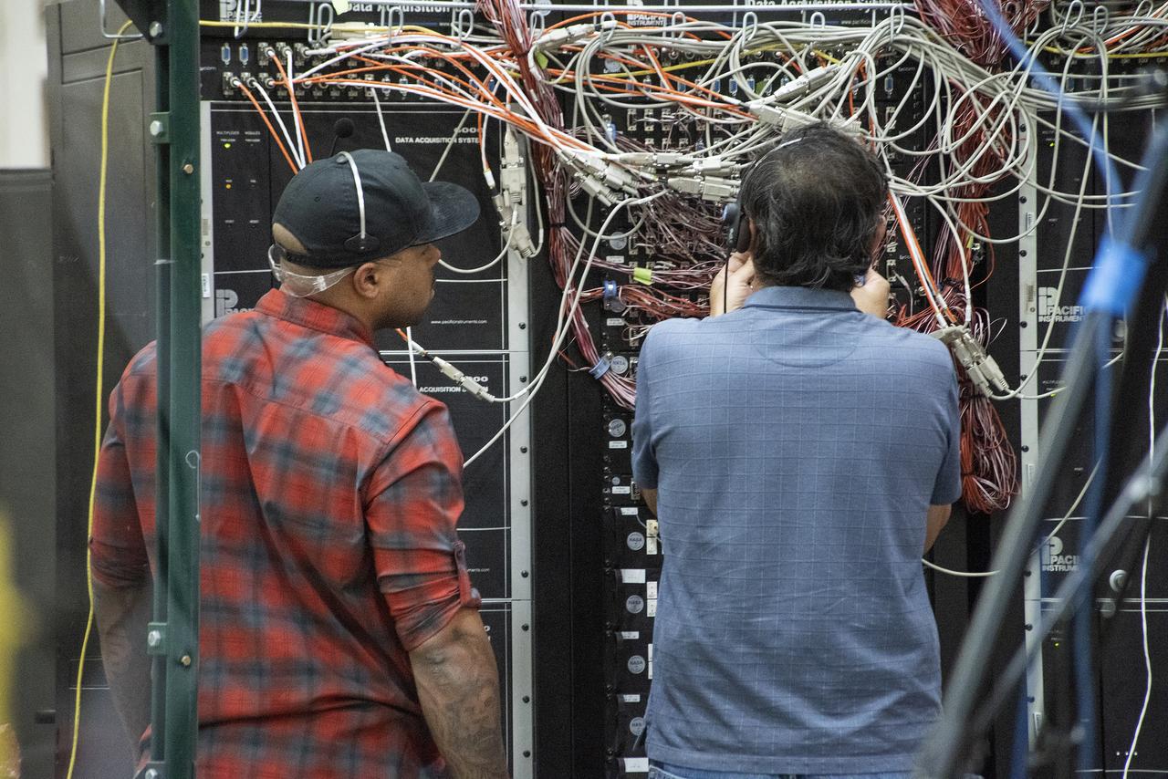
KENNEDY SPACE CENTER, FLA. -- On Launch Pad 39A, technicians overlook wires and monitoring equipment that will be used to validate the circuit on the test wiring from the electrical harness in space shuttle Atlantis' aft main engine compartment connected with the engine cut-off system. The test wiring leads from the tail mast on the mobile launcher platform to the interior where the Time Domain Reflectometry, or TDR, test equipment will be located to test the sensor system. Photo credit: NASA/Kim Shiflett
A short during liftoff of Space Shuttle Columbia in July was traced to a wire in the payload bay with damaged insulation. As a result of that problem, NASA decided to inspect much of the wiring in all four Space Shuttles and make repairs as required. Here technicians are examining, repairing and protecting the wires onboard orbiter Discovery as necessary. The next Shuttle mission, STS-103, the Third Hubble Space Telescope Servicing Mission, is currently scheduled for launch no earlier than Nov. 19, 1999
KENNEDY SPACE CENTER, FLA. -- On Launch Pad 39A at NASA's Kennedy Space Center, a technician sets up wiring for the tanking test on space shuttle Atlantis' external tank set for Dec. 18. The test wiring has been spliced into an electrical harness in the aft main engine compartment connected with the engine cut-off, or ECO, sensor system. The attached wiring leads to the interior of the mobile launcher platform where the time domain reflectometry, or TDR, test equipment is located. Photo credit: NASA/Kim Shiflett
A short during liftoff of Space Shuttle Columbia in July was traced to a wire in the payload bay with damaged insulation. As a result of that problem, NASA decided to inspect much of the wiring in all four Space Shuttles and make repairs as required. Two technicians at the back of the open bay are examining, repairing and protecting the wires onboard orbiter Endeavour as needed. The next Shuttle mission, STS-103, the Third Hubble Space Telescope Servicing Mission, is currently scheduled for launch no earlier than Nov. 19, 1999
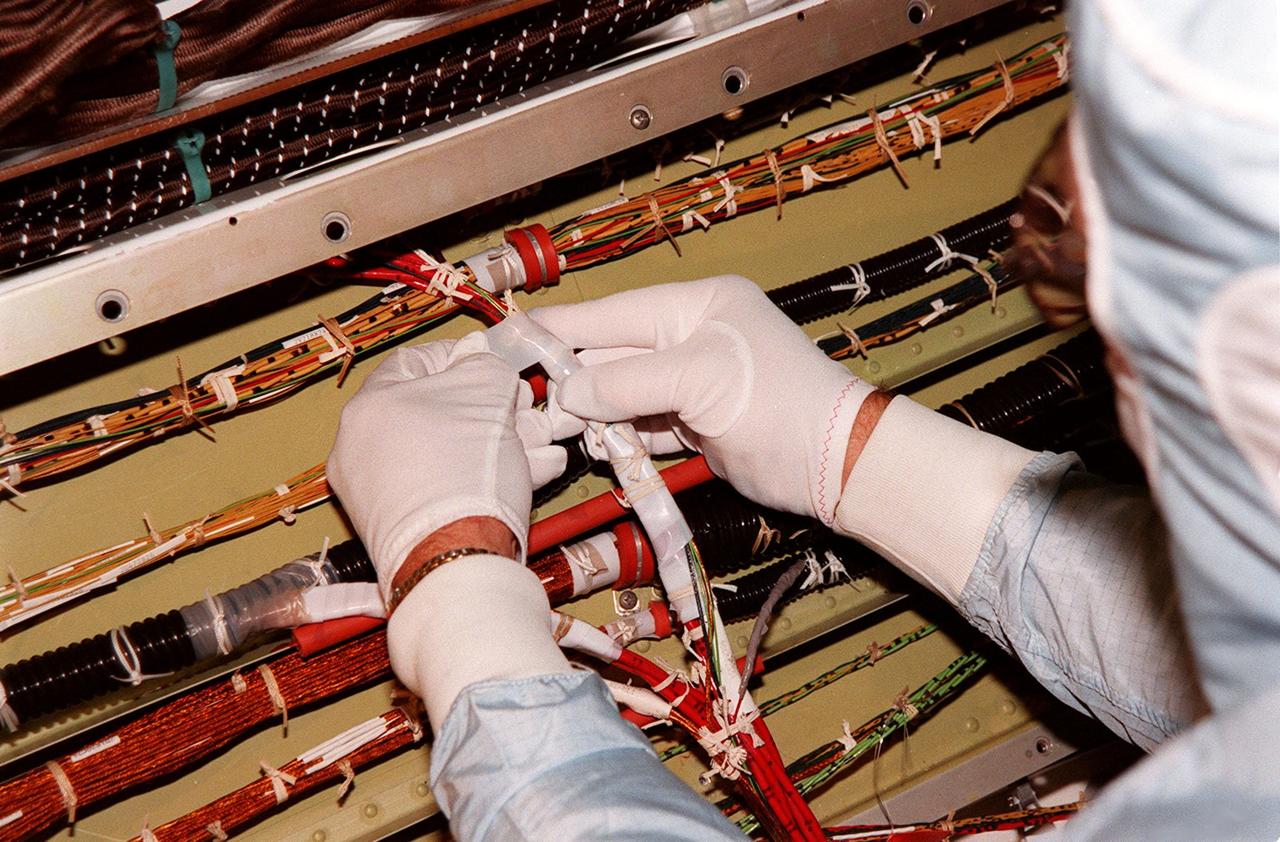
A short during liftoff of Space Shuttle Columbia in July was traced to a wire in the payload bay with damaged insulation. As a result of that problem, NASA decided to inspect much of the wiring in all four Space Shuttles and make repairs as required. Here a technician is protecting the wires onboard orbiter Discovery. The next Shuttle mission, STS-103, the Third Hubble Space Telescope Servicing Mission, is currently scheduled for launch no earlier than Nov. 19, 1999
KENNEDY SPACE CENTER, FLA. -- On Launch Pad 39A at NASA's Kennedy Space Center, the wiring is checked and validated before the tanking test on space shuttle Atlantis' external tank set for Dec. 18. The test wiring has been spliced into an electrical harness in the aft main engine compartment connected with the engine cut-off, or ECO, sensor system. The attached wiring leads to the interior of the mobile launcher platform where the time domain reflectometry, or TDR, test equipment is located. Photo credit: NASA/Kim Shiflett
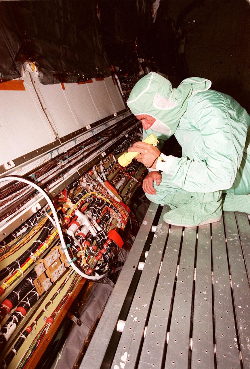
A short during liftoff of Space Shuttle Columbia in July was traced to a wire in the payload bay with damaged insulation. As a result of that problem, NASA decided to inspect much of the wiring in all four Space Shuttles and make repairs as required. Here a technician is examining the wires onboard orbiter Endeavour. The next Shuttle mission, STS-103, the Third Hubble Space Telescope Servicing Mission, is currently scheduled for launch no earlier than Nov. 19, 1999
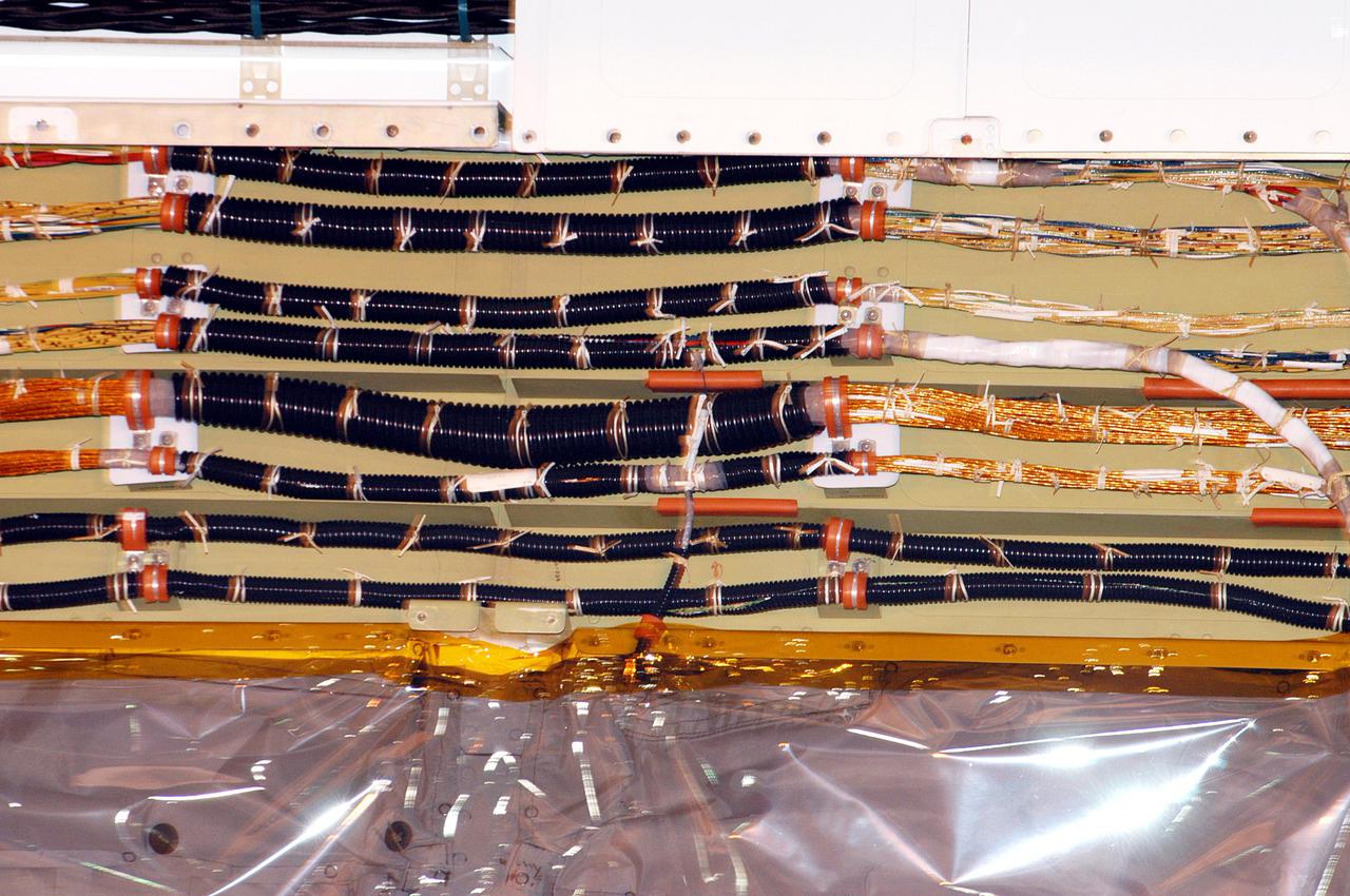
KENNEDY SPACE CENTER, FLA. - In the Orbiter Processing Facility at NASA’s Kennedy Space Center in Florida, workers are removing wire tray covers on Discovery and adding chafe prevention. The wiring is seen here. Boroscope inspections revealed the need for the protection to prevent fasteners from causing minor chafing on the tubing surrounding the wires. Discovery is the designated orbiter for Return to Flight mission STS-114 to the International Space Station. The launch window for the mission is May 15 to June 3, 2005.
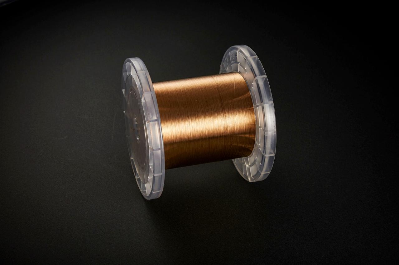
jsc2020e040942 (4/18/2015) --- Copper zirconium alloy wire. The Exposure Experiment of Copper-Zirconium Antenna Metal Mesh to the Space Environment (ExHAM-Antenna Metal Mesh) investigation tests how well an antenna metal mesh, made from copper and zirconium, performs in the space environment in low-Earth orbit (LEO). While in space, the antenna metal mesh is exposed to cosmic rays and atomic oxygen in the LEO space environment - which can degrade antenna performance. Image Credit: NGK Insulators, Ltd., Taiyo Wire Cloth Co., Ltd., Technosolver Corporation, Koyo Materica Corporation, JAXA..
jsc2020e040941 (9/3/2018) --- Copper zirconium alloy wire being produced. The Exposure Experiment of Copper-Zirconium Antenna Metal Mesh to the Space Environment (ExHAM-Antenna Metal Mesh) investigation tests how well an antenna metal mesh, made from copper and zirconium, performs in the space environment in low-Earth orbit (LEO). While in space, the antenna metal mesh is exposed to cosmic rays and atomic oxygen in the LEO space environment - which can degrade antenna performance. Image Credit: NGK Insulators, Ltd., Taiyo Wire Cloth Co., Ltd., Technosolver Corporation, Koyo Materica Corporation, JAXA..
jsc2020e040940 (9/3/2018) --- Copper zirconium alloy wire being produced. The Exposure Experiment of Copper-Zirconium Antenna Metal Mesh to the Space Environment (ExHAM-Antenna Metal Mesh) investigation tests how well an antenna metal mesh, made from copper and zirconium, performs in the space environment in low-Earth orbit (LEO). While in space, the antenna metal mesh is exposed to cosmic rays and atomic oxygen in the LEO space environment - which can degrade antenna performance. Image Credit: NGK Insulators, Ltd., Taiyo Wire Cloth Co., Ltd., Technosolver Corporation, Koyo Materica Corporation, JAXA..
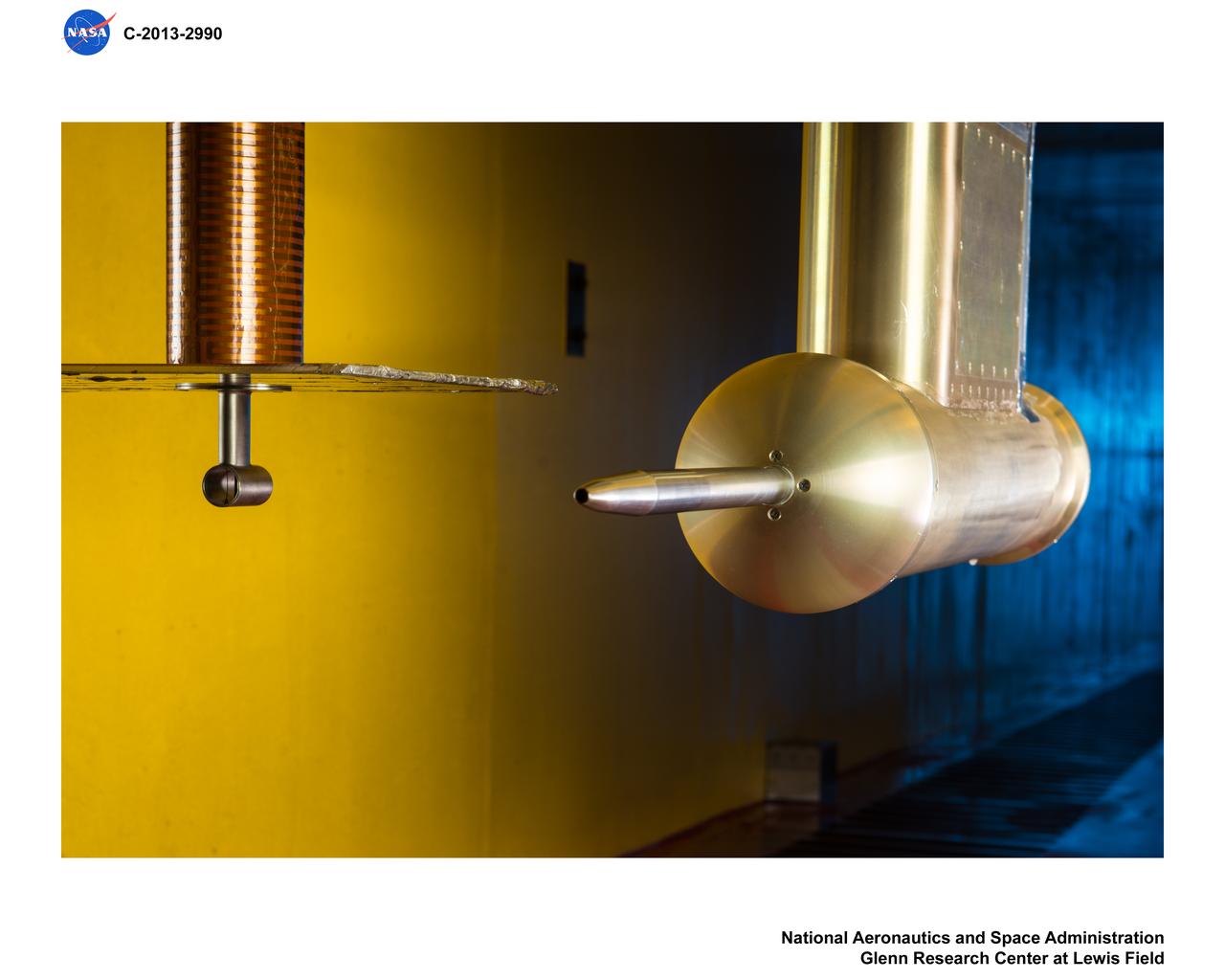
Isokinetic and Multi Wire Probes in the Icing Research Tunnel, IRT, Test Section
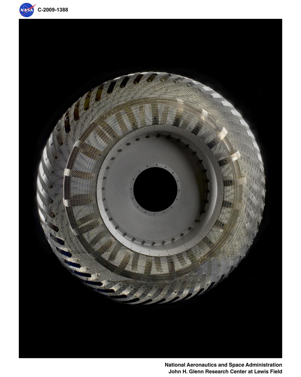
Wire Mesh Tire from the Simulated Lunar Operations Laboratory (SLOPE Lab)
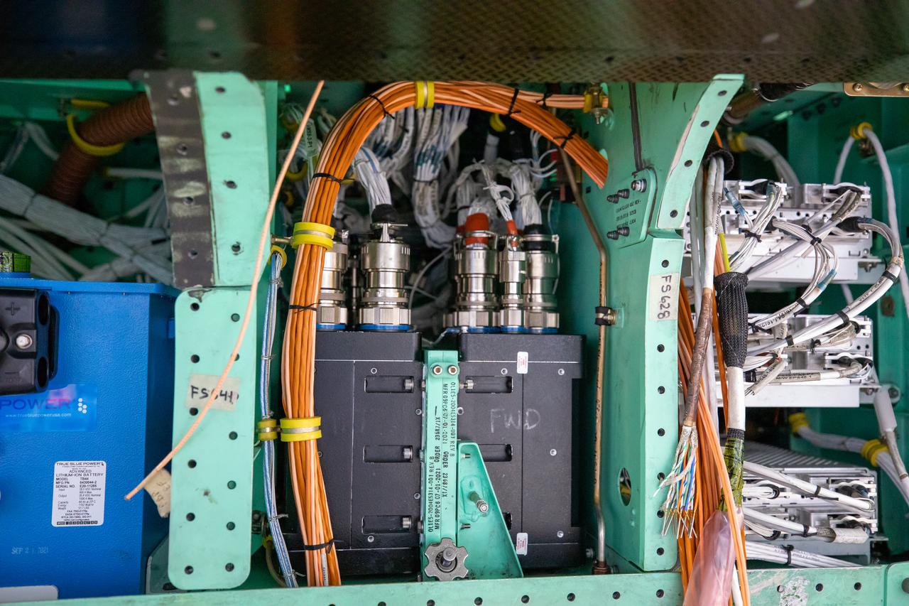
This is a closeup view of the inner workings of the X-59 aircraft. Visible are one the plane’s three lithium-ion batteries (blue box), electrical power system and other wiring components including the vehicle management systems computers (two black boxes) and the white wirings which assist in providing the power that is needed for the aircraft to function in flight. All of these components are essential to maintaining and monitoring the X-59 once it takes to the skies. The X-59 is the centerpiece of the Quesst mission which plans to help enable commercial supersonic air travel over land.
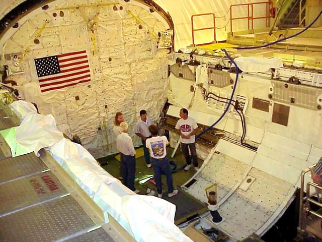
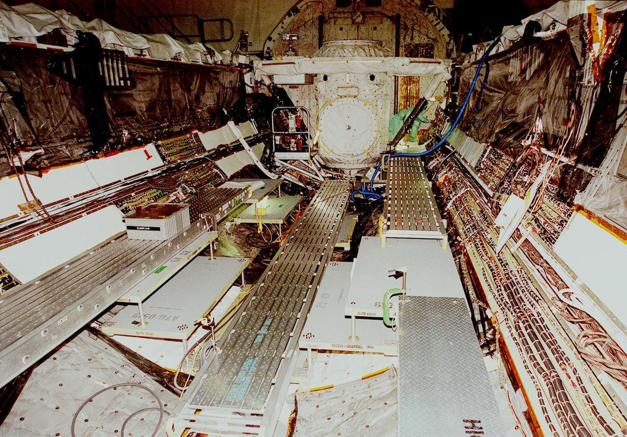
KENNEDY SPACE CENTER, FLA. -- KSC workers stand inside the payload bay of the orbiter Columbia following completion of electrical wiring inspections. At right, behind and below them is the cable tray with the wiring. During launch of Columbia on mission STS-93, a damaged wire caused a short circuit in two separate main engine controllers. As a result of the findings, Shuttle program managers decided to conduct inspections of the wiring in Endeavour's payload bay before its next mission, STS-99. The inspection and possible repair work will lead to a delayed launch date no earlier than Oct.7. The primary payload of the mission is the Shuttle Radar Topography Mission, a specially modified radar system that will gather data for the most accurate and complete topographic map of the Earth's surface that has ever been assembled
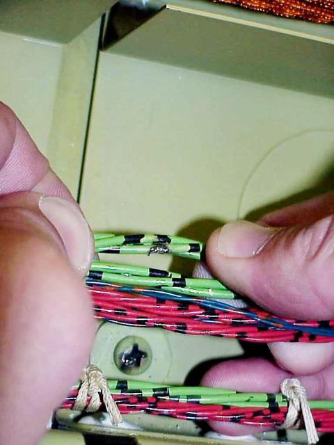
KENNEDY SPACE CENTER, FLA. -- A wire damaged by abrasion from the head of a screw (seen below the bundle) was found during electrical wiring inspections in Columbia's payload bay. During launch of Columbia on mission STS-93, a damaged wire caused a short circuit in two separate main engine controllers. As a result of the findings, Shuttle program managers have decided to conduct inspections of the wiring in Endeavour's payload bay before its next mission, STS-99. The inspection and possible repair work will lead to a delayed launch date no earlier than Oct.7. The primary payload of the mission is the Shuttle Radar Topography Mission, a specially modified radar system that will gather data for the most accurate and complete topographic map of the Earth's surface that has ever been assembled
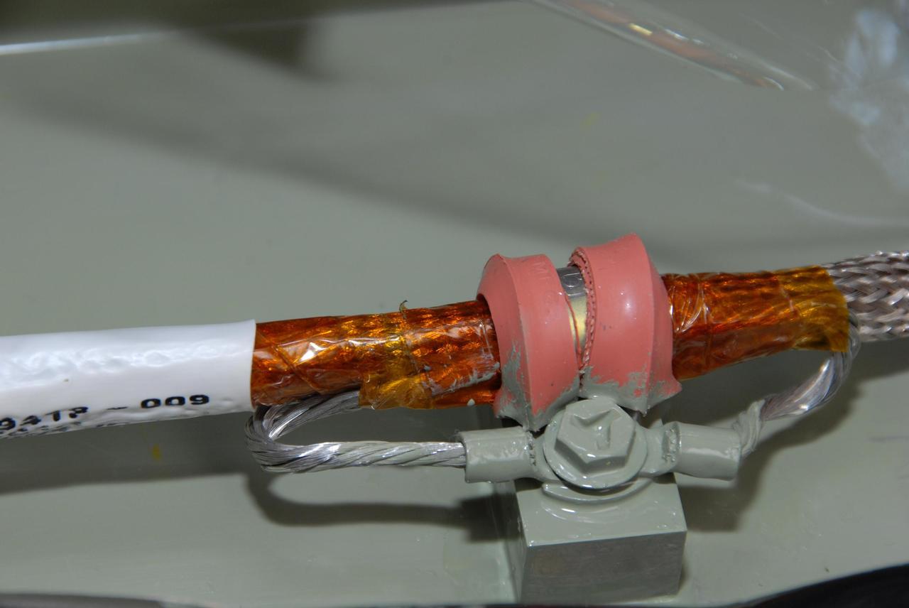
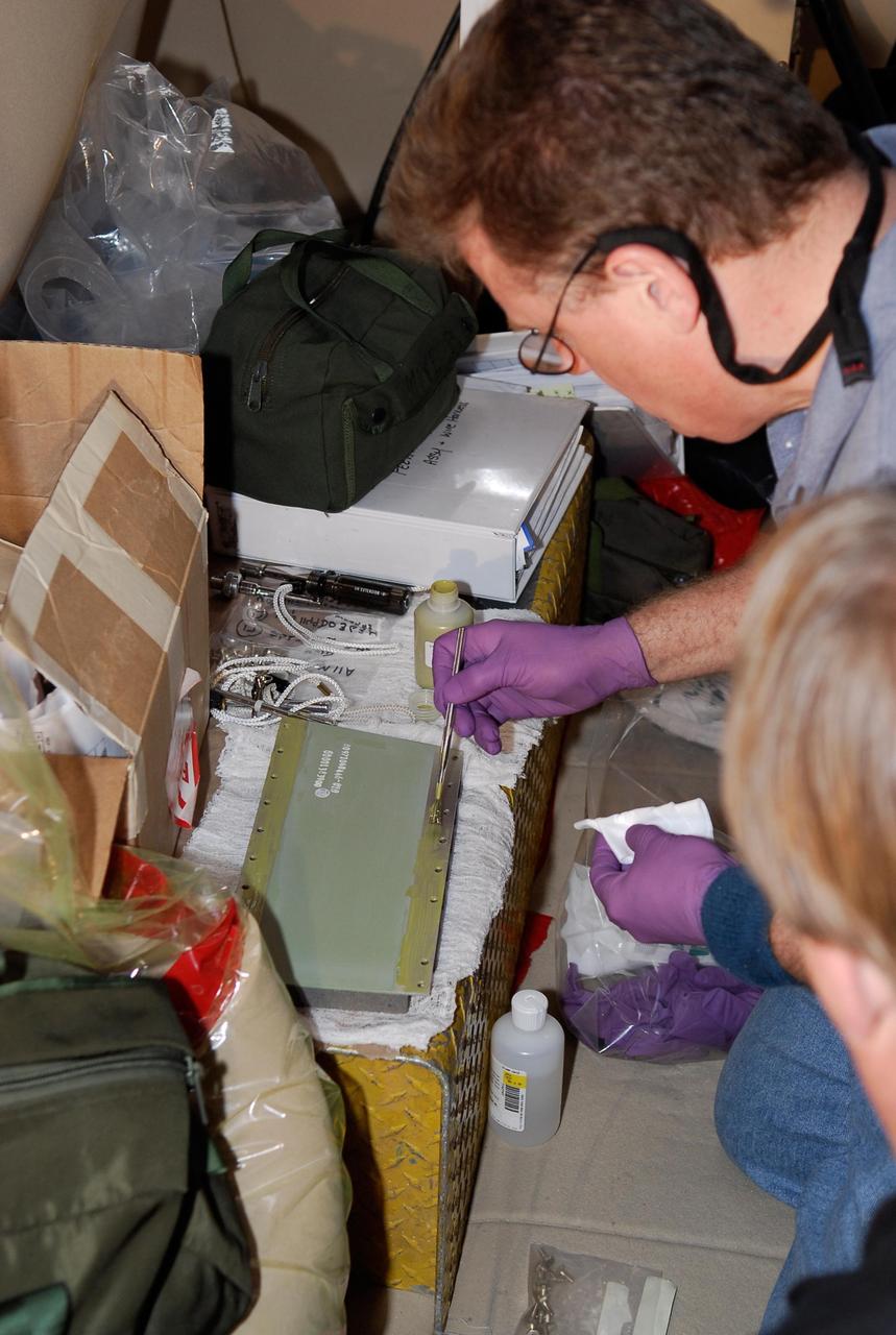
KENNEDY SPACE CENTER, FLA. -- This closeup shows the final splicing completed on the wiring between space shuttle Atlantis' external tank and the engine cutoff, or ECO, sensor system before the replacement feed-through connector in the ECO sensor system is installed. Cryogenic shielding is installed around the wiring. The feed-through connector passes the wires from the inside of the tank to the outside. Results of a tanking test on Dec. 18 pointed to an open circuit in the feed-through connector wiring, which is located at the base of the tank. The pins in the replacement connector have been precisely soldered to create a connection that allows sensors inside the tank to send signals to the computers onboard Atlantis. The work is being done on Launch Pad 39A. Space shuttle Atlantis is now targeted for launch on Feb. 7. Photo credit: NASA/George Shelton
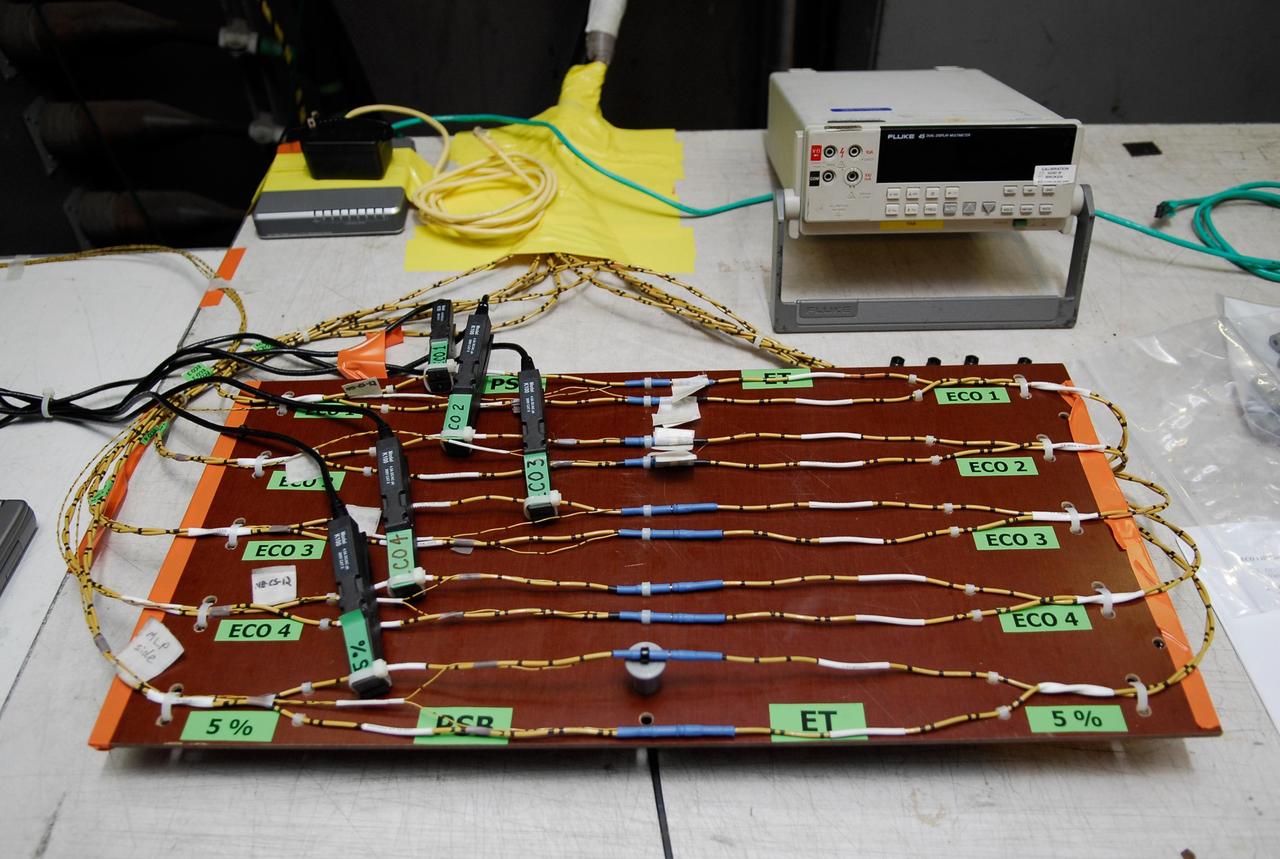
KENNEDY SPACE CENTER, FLA. -- On Launch Pad 39A at NASA's Kennedy Space Center, a wiring board has been set up for the tanking test on space shuttle Atlantis' external tank set for Dec. 18. The test wiring has been spliced into an electrical harness in the aft main engine compartment connected with the engine cut-off, or ECO, sensor system. The attached wiring leads to the interior of the mobile launcher platform where the time domain reflectometry, or TDR, test equipment is located. Photo credit: NASA/Kim Shiflett
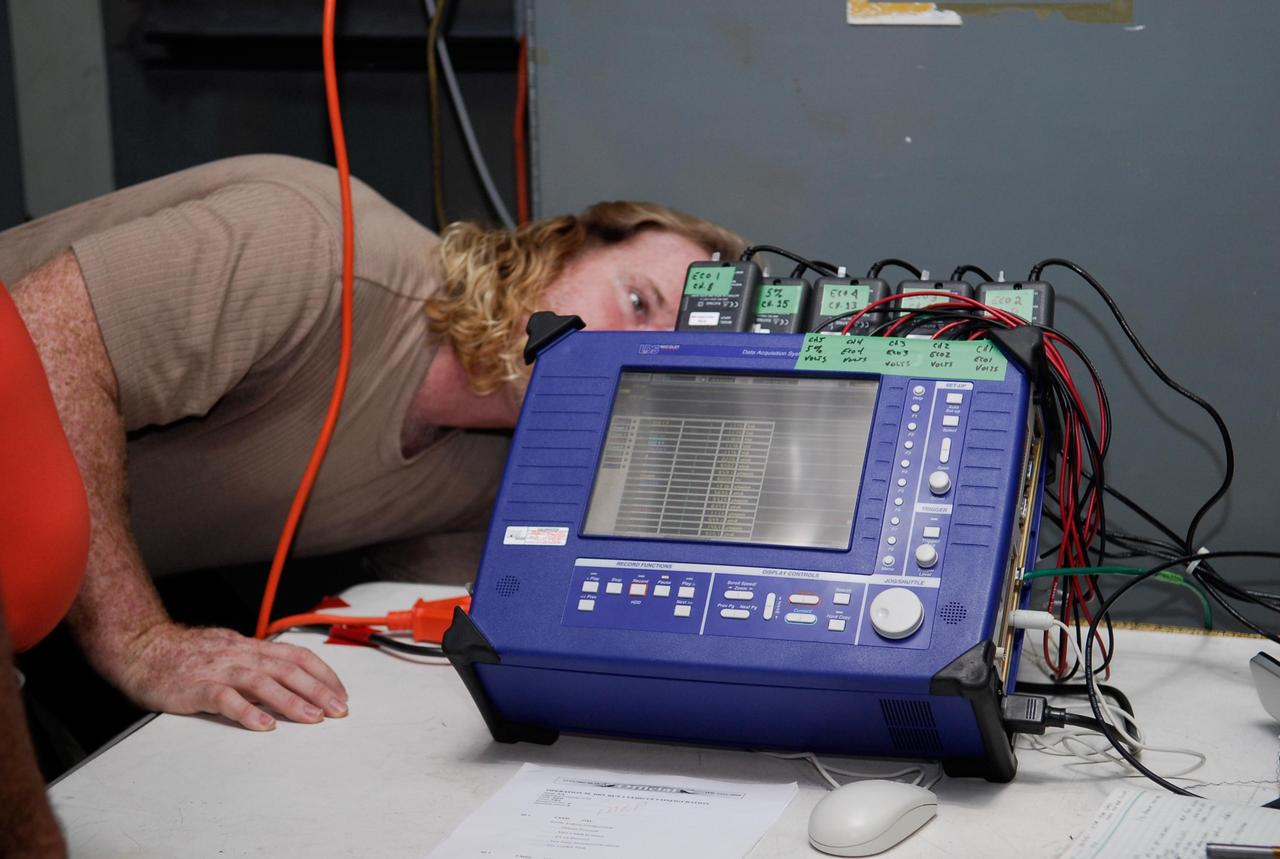
KENNEDY SPACE CENTER, FLA. -- On Launch Pad 39A at NASA's Kennedy Space Center, a technician checks the blue monitor that will be used to validate the circuit on test wiring during the tanking test on space shuttle Atlantis' external tank. The test wiring has been spliced into an electrical harness in the aft main engine compartment connected with the engine cut-off, or ECO, sensor system. The attached wiring leads to the interior of the mobile launcher platform where the time domain reflectometry, or TDR, test equipment is located. Photo credit: NASA/Kim Shiflett
NASA researchers James Cowart and Elizabeth Nail add sensors, wiring and cameras, to the NASA Airborne Instrumentation for Real-world Video of Urban Environments (AIRVUE) sensor pod at NASA’s Armstrong Flight Research Center in Edwards, California in late February 2024. The AIRVUE pod was flown on a helicopter at NASA’s Kennedy Space Center in Florida and is used to collect data for future autonomous aircraft.
Eric Sinks, left, and Ron Haraguchi work through a challenge with the wiring from the Passive Aeroelastic Tailored wing to the test fixture.
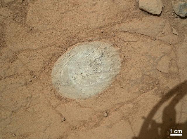
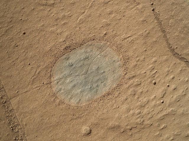
This image from the Mars Hand Lens Imager on NASA Mars rover Curiosity shows the patch of rock cleaned by the first use of the rover Dust Removal Tool DRT. The tool is a motorized, wire-bristle brush on the turret at the end of the rover arm.
Here is a closeup of some of the X-59’s wiring and instrumentation system. Displayed here is the remote instrumentation encoder, which can be found in the wing of the aircraft. This encoder communicates with the plane’s other instrumentation systems like pressure and temperature sensors within the X-59.
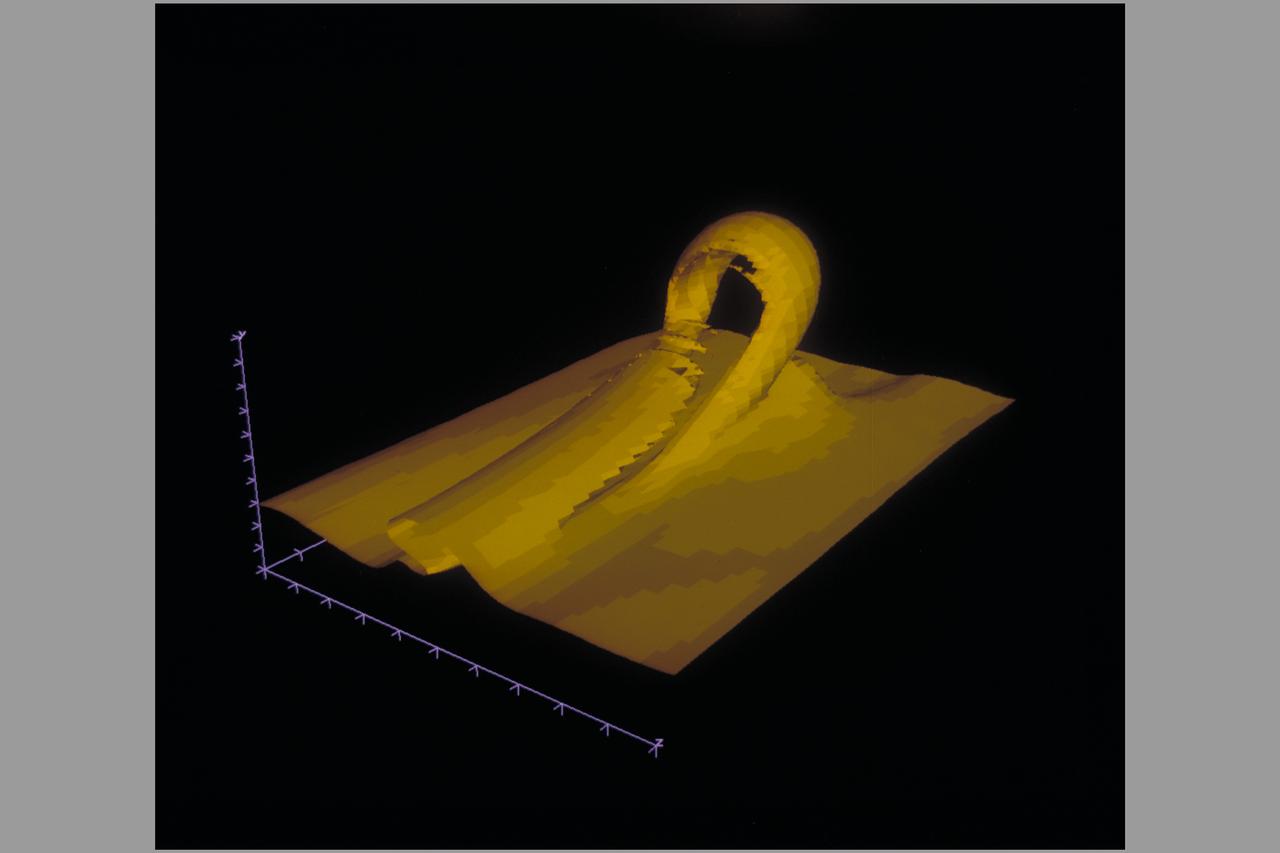
Date: Feb 11, 1987 Photographer: CFD Reynolds Shear Stress: Horseshoe Vortex and Bursting Process Turbulent Boundry Layer (Vertical Wire)
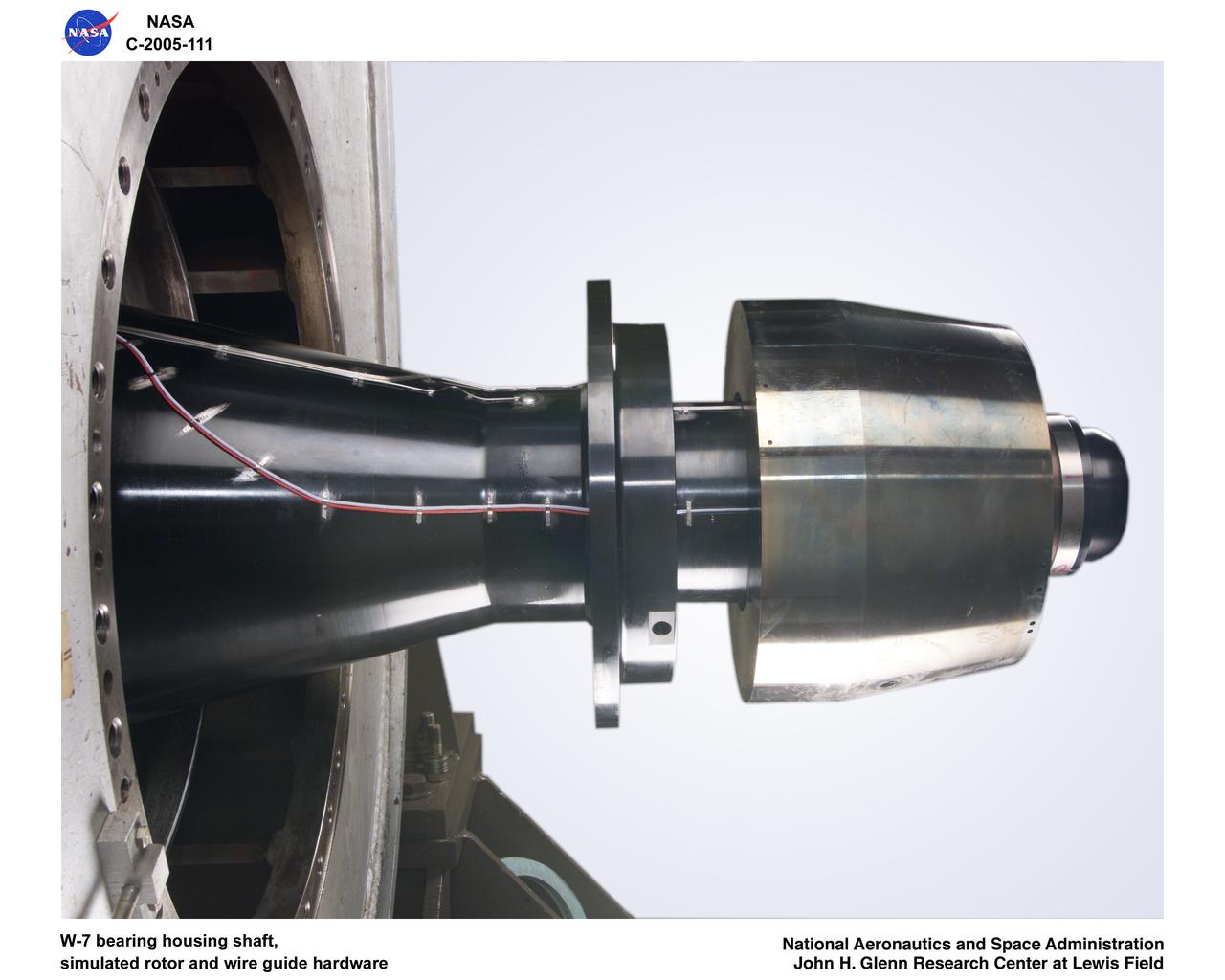
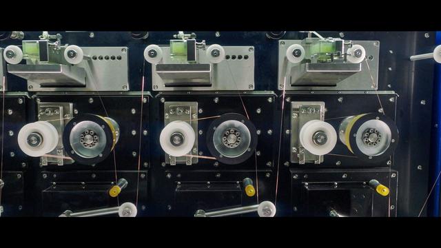
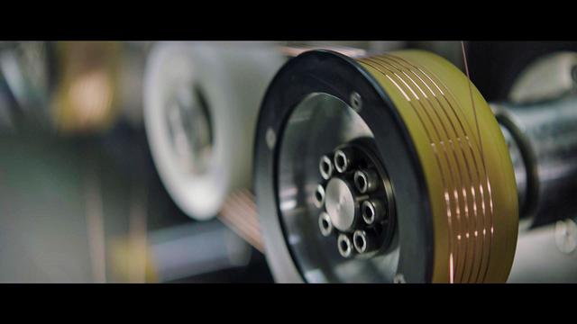
Ultra-Efficient Engine Technology (UEET), Proof of Concept Compressor, W-7 bearing housing shaft, simulated rotor wire guide hardware
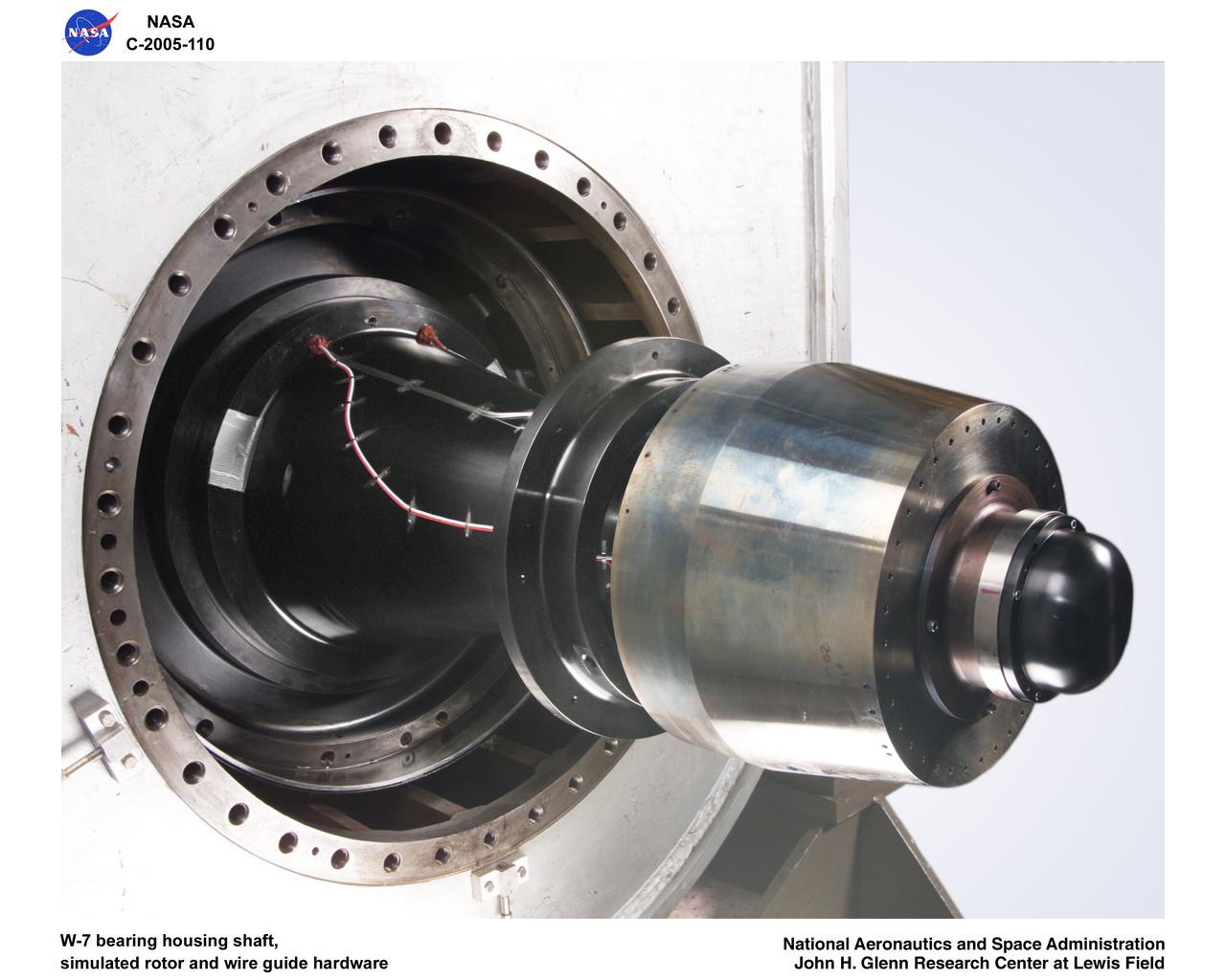
Ultra-Efficient Engine Technology (UEET), Proof of Concept Compressor, W-7 bearing housing shaft, simulated rotor wire guide hardware

The F-8 Digital Fly-By-Wire aircraft had its hydro-mechanical control systems replaced by an Apollo Guidance Computer for the first such control system to fly.
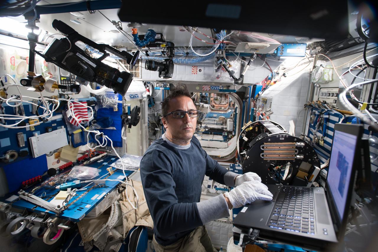
iss054e014673 (Jan. 5, 2018) --- Astronaut Joe Acaba works on wire connections and other maintenance tasks inside Combustion Integrated Rack gear.
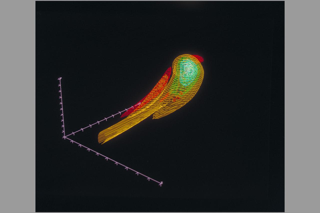
Date: Feb 11, 1987 Photographer: CFD Reynolds Shear Stress: Horseshoe Vortex and Bursting Process Turbulent Boundry Layer (Vertical Wire)
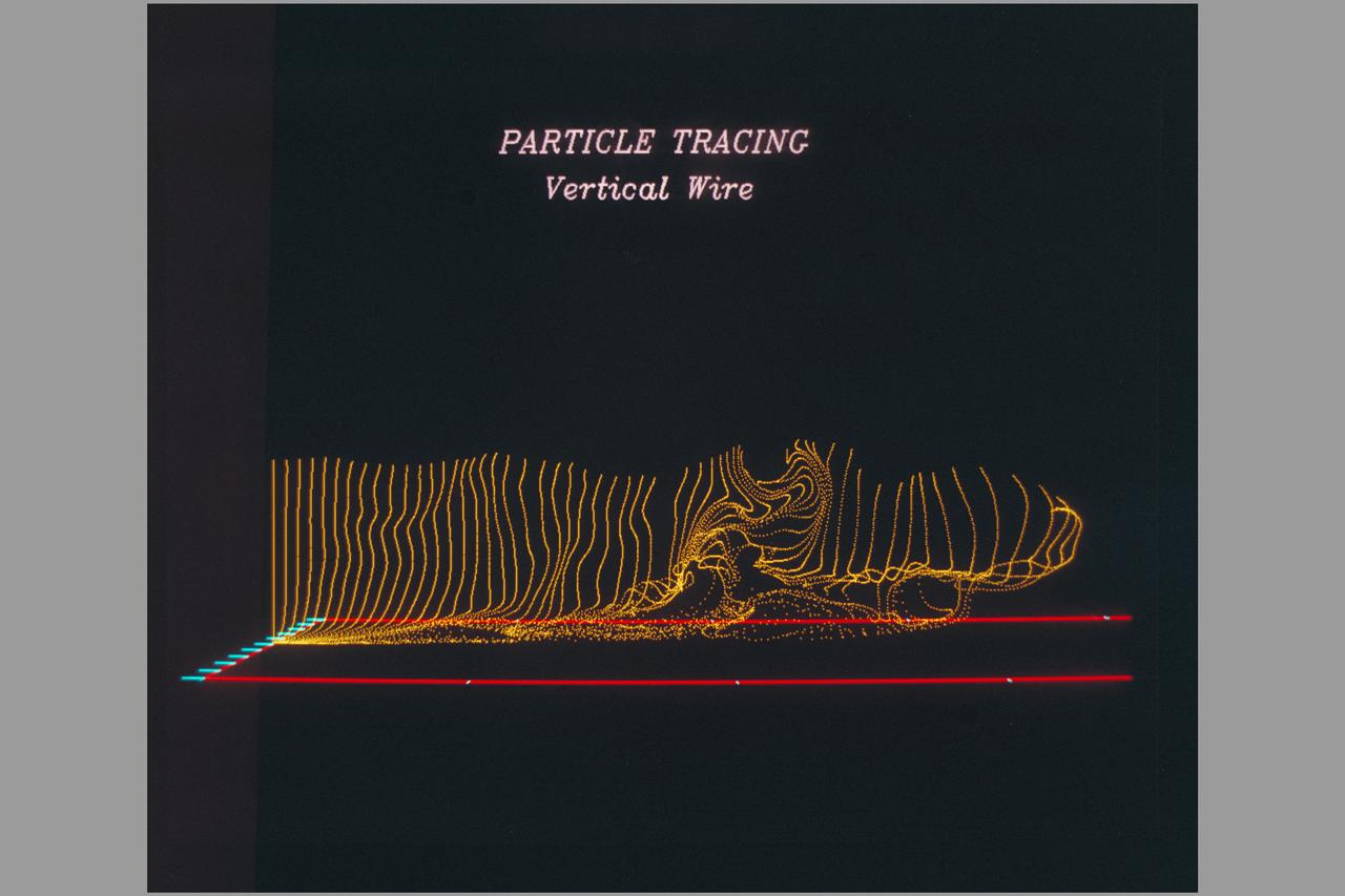
Date: Feb 11, 1987 Photographer: CFD Reynolds Shear Stress: Horseshoe Vortex and Bursting Process Turbulent Boundry Layer (Vertical Wire)
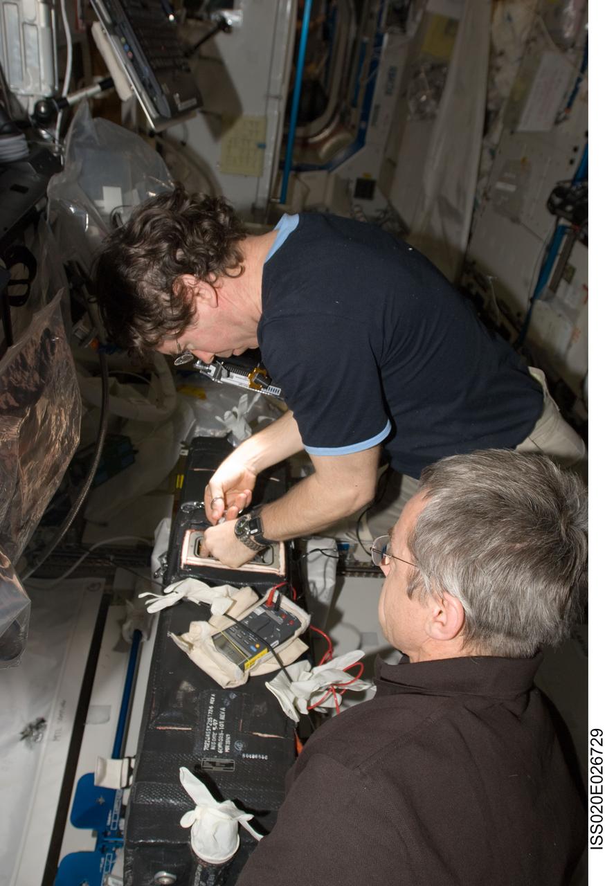
ISS020-E-026729 (31 July 2009) --- NASA astronaut Michael Barratt and Canadian Space Agency astronaut Robert Thirsk (foreground), both Expedition 20 flight engineers, work with the Carbon Dioxide Removal Assembly (CDRA) wire cutting and safing procedures to eliminate shorted heated wires in the Destiny laboratory of the International Space Station.
KENNEDY SPACE CENTER, FLA. - In the Orbiter Processing Facility at NASA’s Kennedy Space Center in Florida, a worker are removing wire tray covers on Discovery and adding chafe prevention. Boroscope inspections revealed the need for the protection to prevent fasteners from causing minor chafing on the tubing surrounding the wires. Discovery is the designated orbiter for Return to Flight mission STS-114 to the International Space Station. The launch window for the mission is May 15 to June 3, 2005.
KENNEDY SPACE CENTER, FLA. - In the Orbiter Processing Facility at NASA’s Kennedy Space Center in Florida, workers are removing wire tray covers on Discovery and adding chafe prevention. Boroscope inspections revealed the need for the protection to prevent fasteners from causing minor chafing on the tubing surrounding the wires. Discovery is the designated orbiter for Return to Flight mission STS-114 to the International Space Station. The launch window for the mission is May 15 to June 3, 2005.
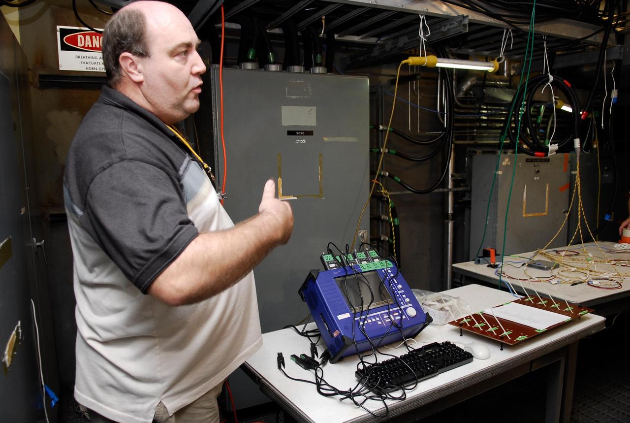
KENNEDY SPACE CENTER, FLA. -- On Launch Pad 39A, a technician explains how test equipment -- the blue monitor -- will be used to validate the circuit on test wiring from the electrical harness in space shuttle Atlantis' aft main engine compartment connected with the engine cut-off system. The test wiring leads from the tail mast on the mobile launcher platform to the interior where the Time Domain Reflectometry, or TDR, test equipment will be located to test the sensor system. Photo credit: NASA/Kim Shiflett
KENNEDY SPACE CENTER, FLA. -- Todd Biddle, with United Space Alliance, inspects wiring in the aft compartment of Discovery before launch. Electrical wire inspections and repairs in the orbiter's payload bay, external tank umbilical and engine compartment have been ongoing for more than a month and are near completion. Launch of Space Shuttle Discovery on mission STS-103 is scheduled for Dec. 11 at 11:42 p.m. from Launch Pad 39B. STS-103 is the third servicing mission for the Hubble Space Telescope

KENNEDY SPACE CENTER, FLA. -- Danny Wyatt, with NASA Quality, inspects wiring, using a flashlight and magnifying glass, in the aft compartment of Discovery before launch. Electrical wire inspections and repairs in the orbiter's payload bay, external tank umbilical and engine compartment have been ongoing for more than a month and are near completion. Launch of Space Shuttle Discovery on mission STS-103 is scheduled for Dec. 11 at 11:42 p.m. from Launch Pad 39B. STS-103 is the third servicing mission for the Hubble Space Telescope
Two engineers evaluate the Emergency Egress System as they ride in folding seats attached to slide wires at Space Launch Complex 41. United Launch Alliance and Boeing continue modifications to the pad in order to host missions by the Boeing CST-100 Starliner carrying astronauts and crew. The system recently completed its final test. In the unlikely event of an emergency prior to liftoff, each person on the Crew Access Tower would get into their own seat attached to the wire and slide more than 1,340 feet to a safe area. The wires are situated 172 feet above the pad deck on level 12 of the tower. The Starliner will launch on a ULA Atlas V on mission to low-Earth orbit including those flying astronauts to the International Space Station during missions by NASA's Commercial Crew Program.
KENNEDY SPACE CENTER, FLA. -- On Launch Pad 39A at NASA's Kennedy Space Center, a technician begins attaching the cover over the engine cutoff, or ECO, sensor system connector and wiring on space shuttle Atlantis' external tank. The feed-through connector passes the wires from the inside of the tank to the outside. Results of a tanking test on Dec. 18 pointed to an open circuit in the feed-through connector wiring, which is located at the base of the tank. The pins in the replacement connector were precisely soldered to create a connection that allows sensors inside the tank to send signals to the computers onboard Atlantis. The launch date for the shuttle's STS-122 mission has now been targeted for Feb. 7. Photo credit: NASA/Kim Shiflett

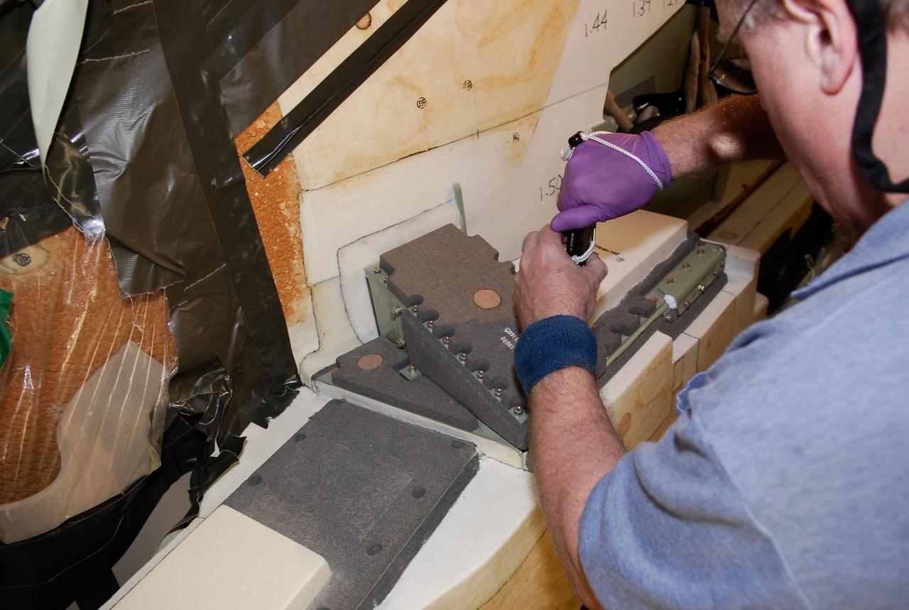
KENNEDY SPACE CENTER, FLA. -- On Launch Pad 39A at NASA's Kennedy Space Center, foam insulation is being trimmed for placement around the engine cutoff, or ECO, sensor system connector and wiring on space shuttle Atlantis' external tank. The foam was removed to enable engineers to remove and replace a feed-through ECO sensor connector on the tank. The feed-through connector passes the wires from the inside of the tank to the outside. Results of a tanking test on Dec. 18 pointed to an open circuit in the feed-through connector wiring, which is located at the base of the tank. The pins in the replacement connector were precisely soldered to create a connection that allows sensors inside the tank to send signals to the computers onboard Atlantis. The launch date for the shuttle's STS-122 mission has now been targeted for Feb. 7. Photo credit: NASA/Kim Shiflett
KENNEDY SPACE CENTER, FLA. -- On Launch Pad 39A at NASA's Kennedy Space Center, technicians prepare the cover to be installed over the engine cutoff, or ECO, sensor system connector and wiring on space shuttle Atlantis' external tank. The feed-through connector passes the wires from the inside of the tank to the outside. Results of a tanking test on Dec. 18 pointed to an open circuit in the feed-through connector wiring, which is located at the base of the tank. The pins in the replacement connector were precisely soldered to create a connection that allows sensors inside the tank to send signals to the computers onboard Atlantis. The launch date for the shuttle's STS-122 mission has now been targeted for Feb. 7. Photo credit: NASA/Kim Shiflett
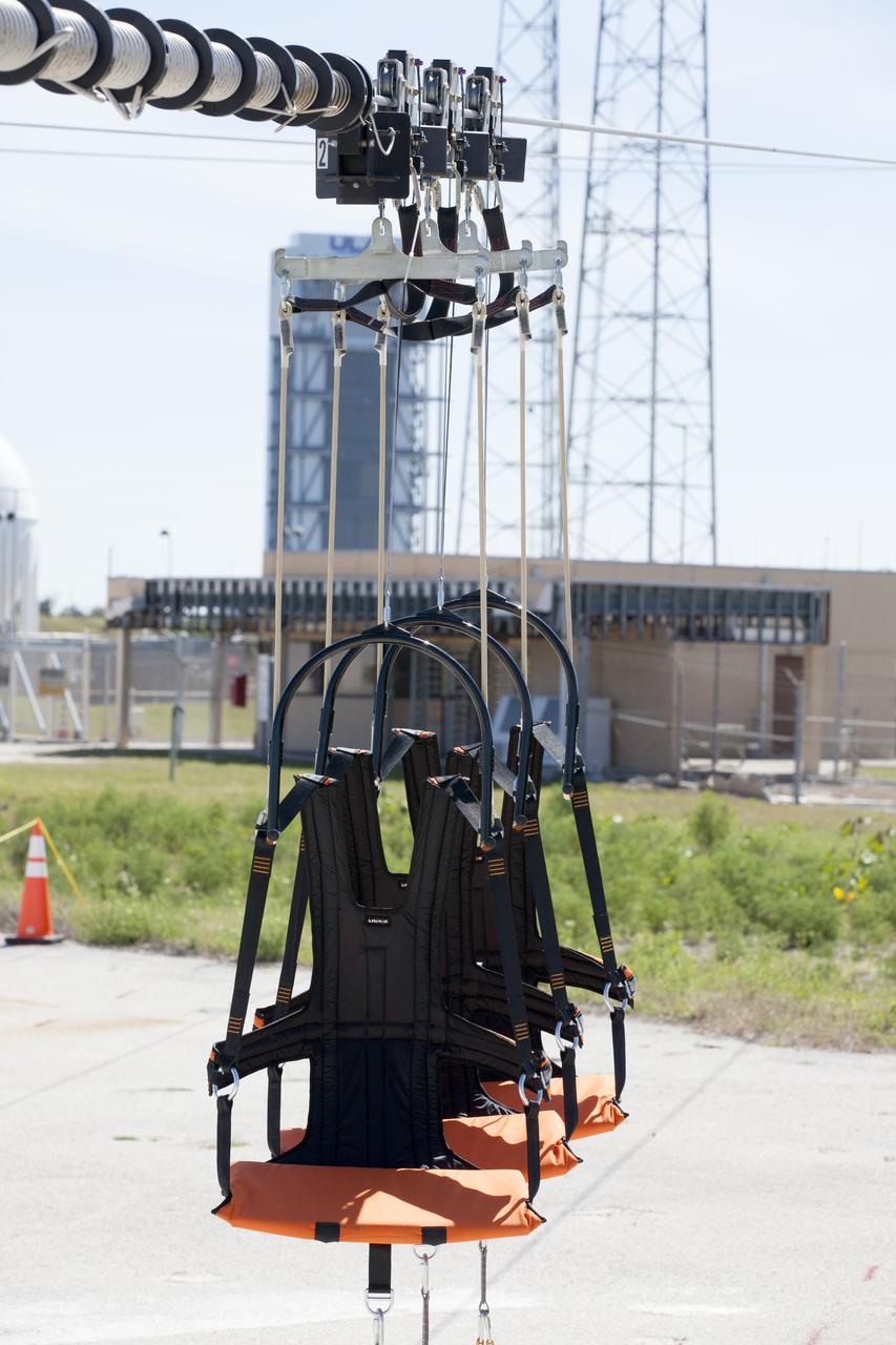
The folding seats that make up the Emergency Egress System are seen attached to slide wires at Space Launch Complex 41 where United Launch Alliance and Boeing continue modifications to the pad in order to host missions by the Boeing CST-100 Starliner carrying astronauts and crew. The system recently completed its final test. In the unlikely event of an emergency prior to liftoff, each person on the Crew Access Tower would get into their own seat attached to the wire and slide more than 1,340 feet to a safe area. The wires are situated 172 feet above the pad deck on level 12 of the tower. The Starliner will launch on a ULA Atlas V on mission to low-Earth orbit including those flying astronauts to the International Space Station during missions by NASA's Commercial Crew Program.
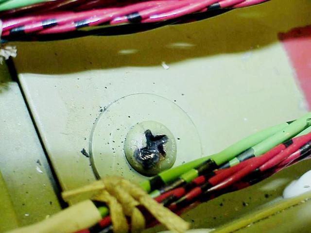
KENNEDY SPACE CENTER, FLA. -- In the orbiter Columbia's payload bay, the head of a screw (shown here) is identified as the probable cause of damage to a wire that caused a short circuit in two separate main engine controllers during launch of mission STS-93. As a result of the findings of electrical wiring inspections, Shuttle program managers have decided to inspect the wiring in Endeavour's payload bay before its next mission, STS-99. The inspection and possible repair work will lead to a delayed launch date no earlier than Oct.7. The primary payload of the mission is the Shuttle Radar Topography Mission, a specially modified radar system that will gather data for the most accurate and complete topographic map of the Earth's surface that has ever been assembled
KENNEDY SPACE CENTER, FLA. - Bill Drier, NASA, is conducting electromagnetic interference and ground resistance testing on wiring in the aft engine compartment on Space Shuttle Discovery using various test equipment, such as current probes, amp meters, digital volt meters, breakout boxes, Nicollet recorders, oscilloscopes and time domain reflectometers. Other testing will evaluate wiring runs and connections for any reactions under semi-cryogenic conditions.Other testing will evaluate wiring runs and connections in the aft engine of Space Shuttle Discovery for any reactions under semi-cryogenic conditions, using a Nicolet data recorder. Engineering teams have been working through a troubleshooting plan to address an issue with a liquid hydrogen low-level fuel sensor circuit. The sensor circuit failed a routine prelaunch check during the countdown July 13, delaying Discovery’s first launch attempt on Return to Flight mission STS-114.
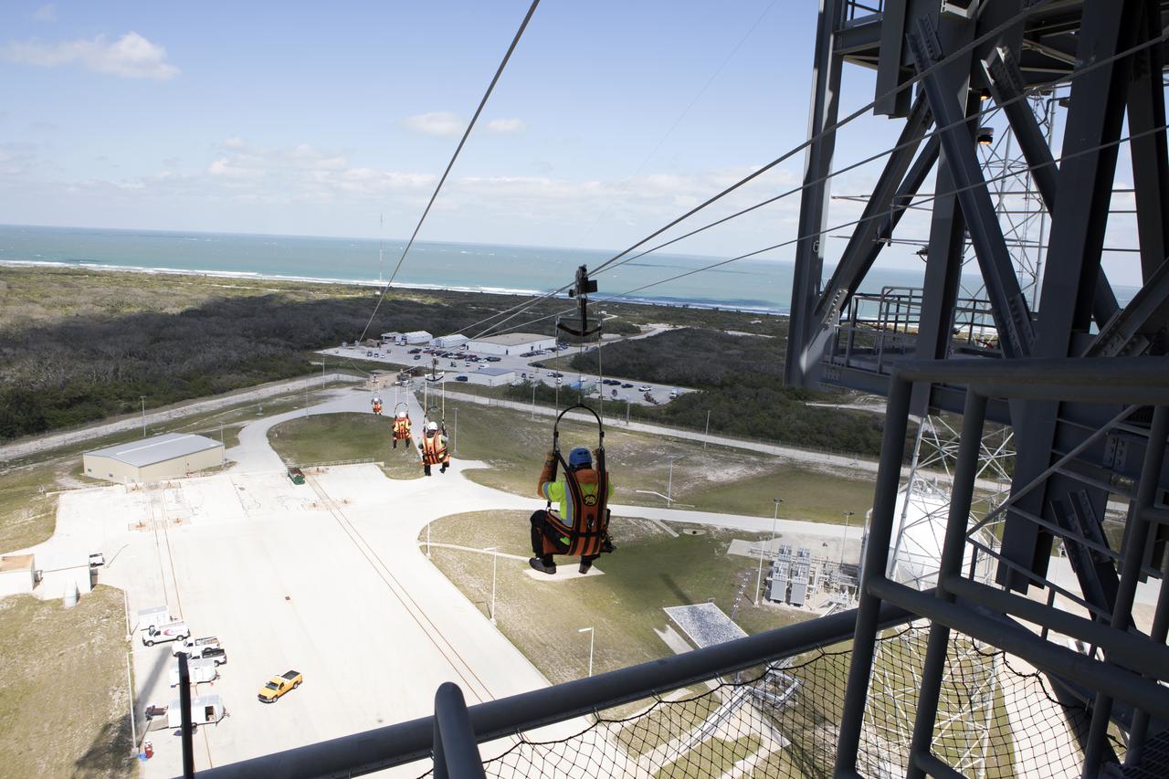
Engineers evaluate the Emergency Egress System as they ride in folding seats attached to slide wires at Space Launch Complex 41. United Launch Alliance and Boeing continue modifications to the pad in order to host missions by the Boeing CST-100 Starliner carrying astronauts and crew. The system recently completed its final test. In the unlikely event of an emergency prior to liftoff, each person on the Crew Access Tower would get into their own seat attached to the wire and slide more than 1,340 feet to a safe area. The wires are situated 172 feet above the pad deck on level 12 of the tower. The Starliner will launch on a ULA Atlas V on mission to low-Earth orbit including those flying astronauts to the International Space Station during missions by NASA's Commercial Crew Program.
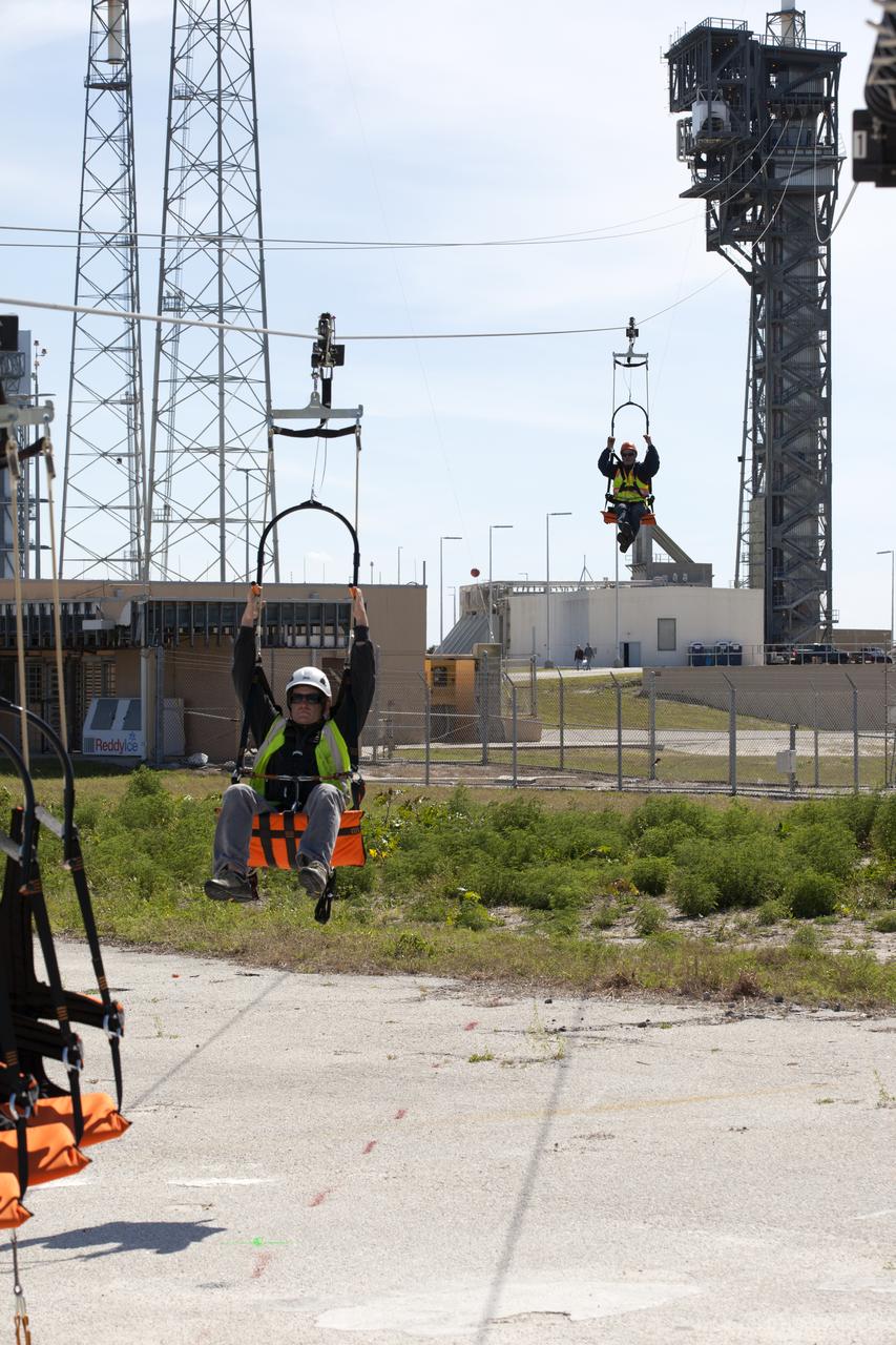
Two engineers evaluate the Emergency Egress System as they ride in folding seats attached to slide wires at Space Launch Complex 41. United Launch Alliance and Boeing continue modifications to the pad in order to host missions by the Boeing CST-100 Starliner carrying astronauts and crew. The system recently completed its final test. In the unlikely event of an emergency prior to liftoff, each person on the Crew Access Tower would get into their own seat attached to the wire and slide more than 1,340 feet to a safe area. The wires are situated 172 feet above the pad deck on level 12 of the tower. The Starliner will launch on a ULA Atlas V on mission to low-Earth orbit including those flying astronauts to the International Space Station during missions by NASA's Commercial Crew Program.
KENNEDY SPACE CENTER, FLA. -- On Launch Pad 39A at NASA's Kennedy Space Center, a technician completes installing the cover over the engine cutoff, or ECO, sensor system connector and wiring on space shuttle Atlantis' external tank. The feed-through connector passes the wires from the inside of the tank to the outside. Results of a tanking test on Dec. 18 pointed to an open circuit in the feed-through connector wiring, which is located at the base of the tank. The pins in the replacement connector were precisely soldered to create a connection that allows sensors inside the tank to send signals to the computers onboard Atlantis. The launch date for the shuttle's STS-122 mission has now been targeted for Feb. 7. Photo credit: NASA/Kim Shiflett
KENNEDY SPACE CENTER, FLA. -- On Launch Pad 39A at NASA's Kennedy Space Center, technicians prepare the cover to be installed over the engine cutoff, or ECO, sensor system connector and wiring on space shuttle space shuttle Atlantis' external tank. The feed-through connector passes the wires from the inside of the tank to the outside. Results of a tanking test on Dec. 18 pointed to an open circuit in the feed-through connector wiring, which is located at the base of the tank. The pins in the replacement connector were precisely soldered to create a connection that allows sensors inside the tank to send signals to the computers onboard Atlantis. The launch date for the shuttle's STS-122 mission has now been targeted for Feb. 7. Photo credit: NASA/Kim Shiflett

Engineers evaluate the Emergency Egress System as they ride in folding seats attached to slide wires at Space Launch Complex 41. United Launch Alliance and Boeing continue modifications to the pad in order to host missions by the Boeing CST-100 Starliner carrying astronauts and crew. The system recently completed its final test. In the unlikely event of an emergency prior to liftoff, each person on the Crew Access Tower would get into their own seat attached to the wire and slide more than 1,340 feet to a safe area. The wires are situated 172 feet above the pad deck on level 12 of the tower. The Starliner will launch on a ULA Atlas V on mission to low-Earth orbit including those flying astronauts to the International Space Station during missions by NASA's Commercial Crew Program.
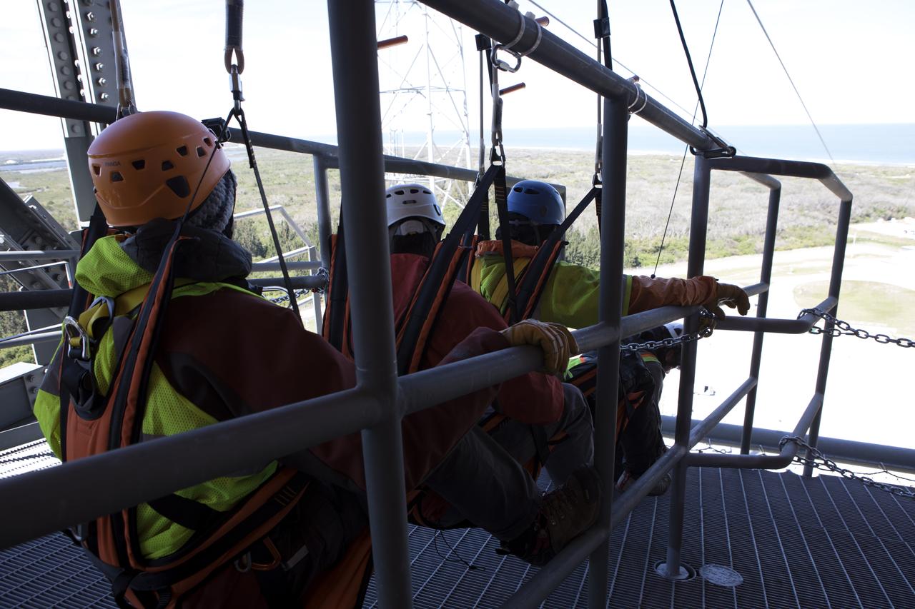
Three engineers prepare to evaluate the Emergency Egress System as they ride in folding seats attached to slide wires at Space Launch Complex 41. United Launch Alliance and Boeing continue modifications to the pad in order to host missions by the Boeing CST-100 Starliner carrying astronauts and crew. The system recently completed its final test. In the unlikely event of an emergency prior to liftoff, each person on the Crew Access Tower would get into their own seat attached to the wire and slide more than 1,340 feet to a safe area. The wires are situated 172 feet above the pad deck on level 12 of the tower. The Starliner will launch on a ULA Atlas V on mission to low-Earth orbit including those flying astronauts to the International Space Station during missions by NASA's Commercial Crew Program.
KENNEDY SPACE CENTER, FLA. -- On Launch Pad 39A at NASA's Kennedy Space Center, a technician trims foam placed around the engine cutoff, or ECO, sensor system connector and wiring on space shuttle Atlantis' external tank. The foam was removed to enable engineers to remove and replace a feed-through ECO sensor connector on the tank. The feed-through connector passes the wires from the inside of the tank to the outside. Results of a tanking test on Dec. 18 pointed to an open circuit in the feed-through connector wiring, which is located at the base of the tank. The pins in the replacement connector were precisely soldered to create a connection that allows sensors inside the tank to send signals to the computers onboard Atlantis. The launch date for the shuttle's STS-122 mission has now been targeted for Feb. 7. Photo credit: NASA/Kim Shiflett

KENNEDY SPACE CENTER, FLA. -- On Launch Pad 39A at NASA's Kennedy Space Center, foam is being replaced around the engine cutoff, or ECO, sensor system connector and wiring on space shuttle Atlantis' external tank. The foam was removed to enable engineers to remove and replace a feed-through ECO sensor connector on the tank. The feed-through connector passes the wires from the inside of the tank to the outside. Results of a tanking test on Dec. 18 pointed to an open circuit in the feed-through connector wiring, which is located at the base of the tank. The pins in the replacement connector were precisely soldered to create a connection that allows sensors inside the tank to send signals to the computers onboard Atlantis. The launch date for the shuttle's STS-122 mission has now been targeted for Feb. 7. Photo credit: NASA/Kim Shiflett
KENNEDY SPACE CENTER, FLA. -- On Launch Pad 39A at NASA's Kennedy Space Center, a technician gets ready to place the cover over the engine cutoff, or ECO, sensor system connector and wiring on space shuttle Atlantis' external tank. The feed-through connector passes the wires from the inside of the tank to the outside. Results of a tanking test on Dec. 18 pointed to an open circuit in the feed-through connector wiring, which is located at the base of the tank. The pins in the replacement connector were precisely soldered to create a connection that allows sensors inside the tank to send signals to the computers onboard Atlantis. The launch date for the shuttle's STS-122 mission has now been targeted for Feb. 7. Photo credit: NASA/Kim Shiflett
KENNEDY SPACE CENTER, FLA. -- On Launch Pad 39A at NASA's Kennedy Space Center, a technician attaches the cover over the engine cutoff, or ECO, sensor system connector and wiring on space shuttle Atlantis' external tank. The feed-through connector passes the wires from the inside of the tank to the outside. Results of a tanking test on Dec. 18 pointed to an open circuit in the feed-through connector wiring, which is located at the base of the tank. The pins in the replacement connector were precisely soldered to create a connection that allows sensors inside the tank to send signals to the computers onboard Atlantis. The launch date for the shuttle's STS-122 mission has now been targeted for Feb. 7. Photo credit: NASA/Kim Shiflett
KENNEDY SPACE CENTER, FLA. -- On Launch Pad 39A at NASA's Kennedy Space Center, foam insulation is being trimmed for placement around the engine cutoff, or ECO, sensor system connector and wiring on space shuttle Atlantis' external tank. The foam was removed to enable engineers to remove and replace a feed-through ECO sensor connector on the tank. The feed-through connector passes the wires from the inside of the tank to the outside. Results of a tanking test on Dec. 18 pointed to an open circuit in the feed-through connector wiring, which is located at the base of the tank. The pins in the replacement connector were precisely soldered to create a connection that allows sensors inside the tank to send signals to the computers onboard Atlantis. The launch date for the shuttle's STS-122 mission has now been targeted for Feb. 7. Photo credit: NASA/Kim Shiflett
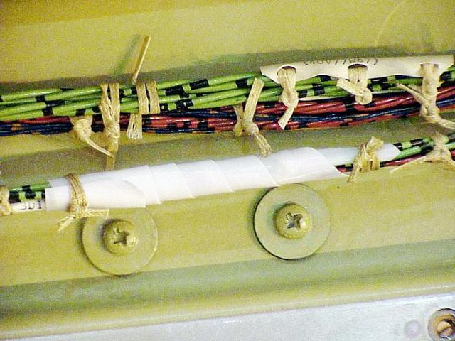
KENNEDY SPACE CENTER, FLA. -- Proper Wiring Protection: The cables closest to the heads of the screws in this photo are properly protected from abrasion. During launch of Columbia on mission STS-93, a wire damaged from abrasion caused a short circuit in two separate main engine controllers. As a result of the findings, Shuttle program managers decided to conduct inspections of the wiring in Endeavour's payload bay before its next mission, STS-99. The inspection and possible repair work will lead to a delayed launch date no earlier than Oct.7. The primary payload of the mission is the Shuttle Radar Topography Mission, a specially modified radar system that will gather data for the most accurate and complete topographic map of the Earth's surface that has ever been assembled
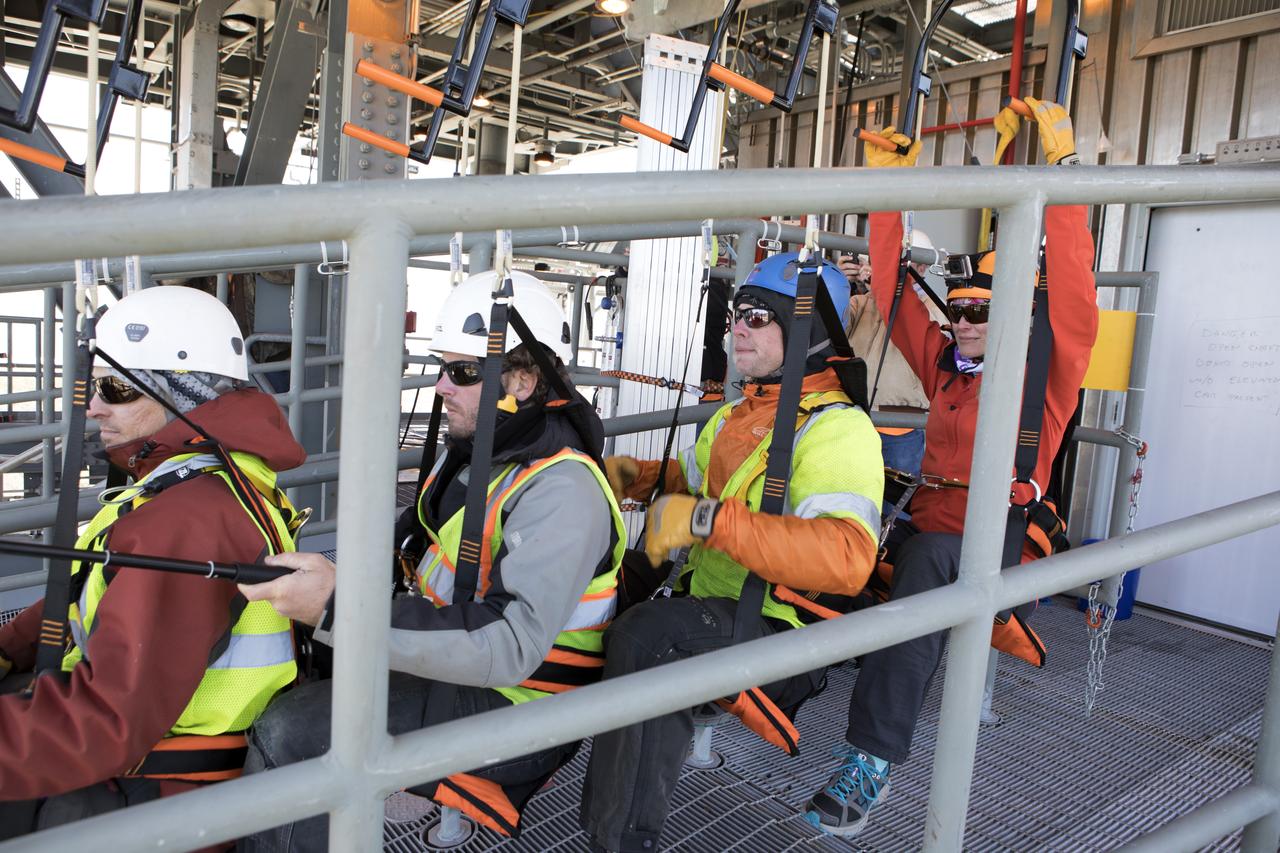
Engineers prepare to evaluate the Emergency Egress System as they ride in folding seats attached to slide wires at Space Launch Complex 41. United Launch Alliance and Boeing continue modifications to the pad in order to host missions by the Boeing CST-100 Starliner carrying astronauts and crew. The system recently completed its final test. In the unlikely event of an emergency prior to liftoff, each person on the Crew Access Tower would get into their own seat attached to the wire and slide more than 1,340 feet to a safe area. The wires are situated 172 feet above the pad deck on level 12 of the tower. The Starliner will launch on a ULA Atlas V on mission to low-Earth orbit including those flying astronauts to the International Space Station during missions by NASA's Commercial Crew Program.
KENNEDY SPACE CENTER, FLA. -- On Launch Pad 39A at NASA's Kennedy Space Center, foam insulation is being trimmed for placement around the engine cutoff, or ECO, sensor system connector and wiring on space shuttle Atlantis' external tank. The foam was removed to enable engineers to remove and replace a feed-through ECO sensor connector on the tank. The feed-through connector passes the wires from the inside of the tank to the outside. Results of a tanking test on Dec. 18 pointed to an open circuit in the feed-through connector wiring, which is located at the base of the tank. The pins in the replacement connector were precisely soldered to create a connection that allows sensors inside the tank to send signals to the computers onboard Atlantis. The launch date for the shuttle's STS-122 mission has now been targeted for Feb. 7. Photo credit: NASA/Kim Shiflett
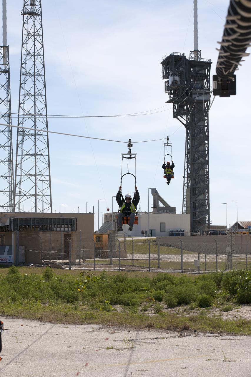
Two engineers evaluate the Emergency Egress System as they ride in folding seats attached to slide wires at Space Launch Complex 41. United Launch Alliance and Boeing continue modifications to the pad in order to host missions by the Boeing CST-100 Starliner carrying astronauts and crew. The system recently completed its final test. In the unlikely event of an emergency prior to liftoff, each person on the Crew Access Tower would get into their own seat attached to the wire and slide more than 1,340 feet to a safe area. The wires are situated 172 feet above the pad deck on level 12 of the tower. The Starliner will launch on a ULA Atlas V on mission to low-Earth orbit including those flying astronauts to the International Space Station during missions by NASA's Commercial Crew Program.
KENNEDY SPACE CENTER, FLA. -- On Launch Pad 39A at NASA's Kennedy Space Center, foam insulation is being trimmed for placement around the engine cutoff, or ECO, sensor system connector and wiring on space shuttle Atlantis' external tank. The foam was removed to enable engineers to remove and replace a feed-through ECO sensor connector on the tank. The feed-through connector passes the wires from the inside of the tank to the outside. Results of a tanking test on Dec. 18 pointed to an open circuit in the feed-through connector wiring, which is located at the base of the tank. The pins in the replacement connector were precisely soldered to create a connection that allows sensors inside the tank to send signals to the computers onboard Atlantis. The launch date for the shuttle's STS-122 mission has now been targeted for Feb. 7. Photo credit: NASA/Kim Shiflett

KENNEDY SPACE CENTER, FLA. -- An orbiter has more than 300 miles of wires such as these shown here in the cable tray inside Columbia's payload bay. During launch of Columbia on mission STS-93, a damaged wire caused a short circuit in two separate main engine controllers. As a result of the findings, Shuttle program managers have decided to conduct inspections of the wiring in Endeavour's payload bay before its next mission, STS-99. The inspection and possible repair work will lead to a delayed launch date no earlier than Oct.7. The primary payload of the mission is the Shuttle Radar Topography Mission, a specially modified radar system that will gather data for the most accurate and complete topographic map of the Earth's surface that has ever been assembled
KENNEDY SPACE CENTER, FLA. -- On Launch Pad 39A at NASA's Kennedy Space Center, foam is being replaced around the engine cutoff, or ECO, sensor system connector and wiring on space shuttle Atlantis' external tank. The foam was removed to enable engineers to remove and replace a feed-through ECO sensor connector on the tank. The feed-through connector passes the wires from the inside of the tank to the outside. Results of a tanking test on Dec. 18 pointed to an open circuit in the feed-through connector wiring, which is located at the base of the tank. The pins in the replacement connector were precisely soldered to create a connection that allows sensors inside the tank to send signals to the computers onboard Atlantis. The launch date for the shuttle's STS-122 mission has now been targeted for Feb. 7. Photo credit: NASA/Kim Shiflett