
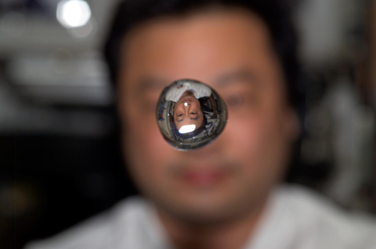
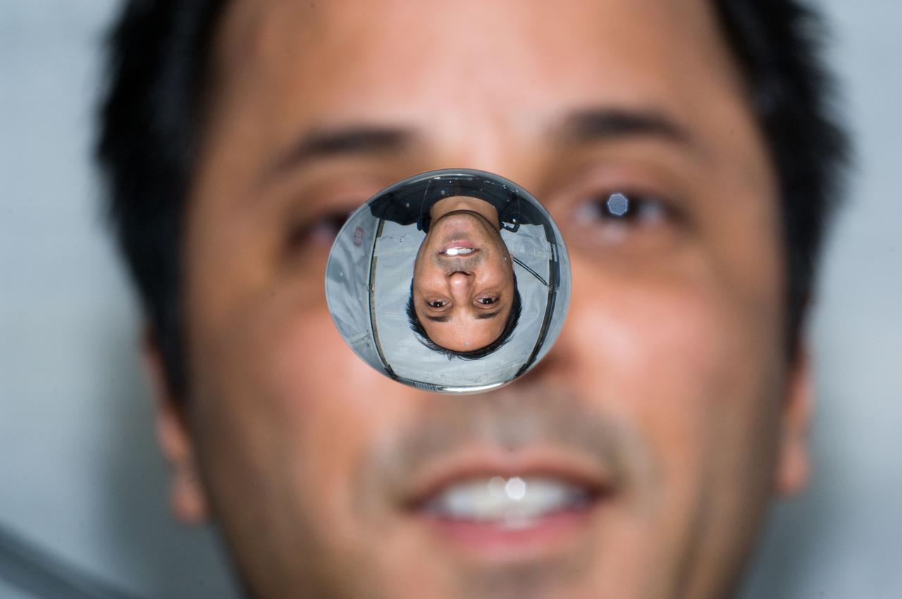
Aboard the International Space Station (ISS), European Space Agency astronaut Pedro Duque of Spain watches a water bubble float between a camera and himself. The bubble shows his reflection (reversed). Duque was launched aboard a Russian Soyuz TMA-3 spacecraft from the Baikonur Cosmodrome, Kazakhstan on October 18th, along with expedition-8 crew members Michael C. Foale, Mission Commander and NASA ISS Science Officer, and Cosmonaut Alexander Y. Kaleri, Soyuz Commander and flight engineer.
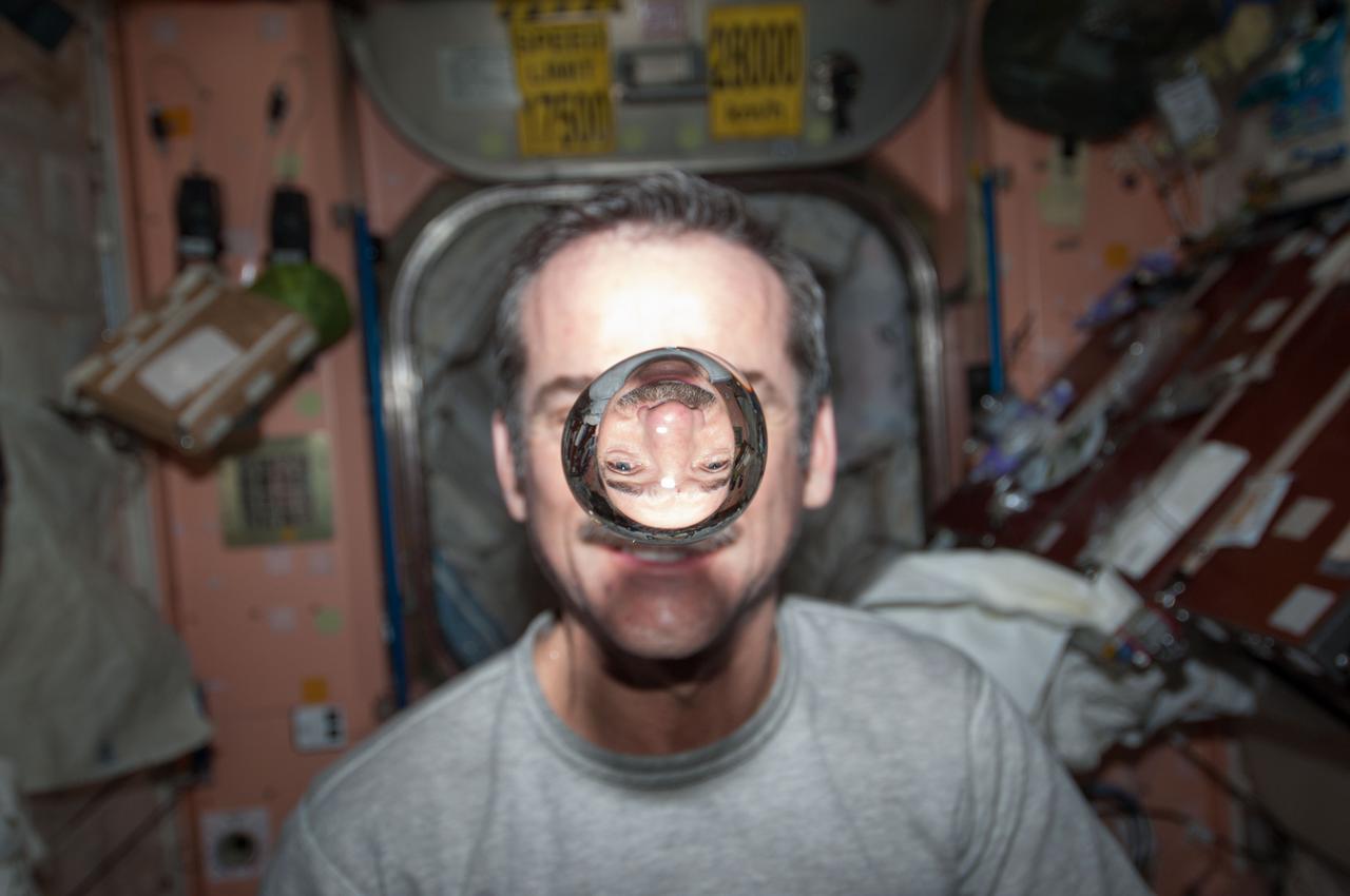
ISS034-E-031694 (21 Jan. 2013) --- Canadian Space Agency astronaut Chris Hadfield, Expedition 34 flight engineer, watches a water bubble float freely between him and the camera, showing his image refracted, in the Unity node of the International Space Station.
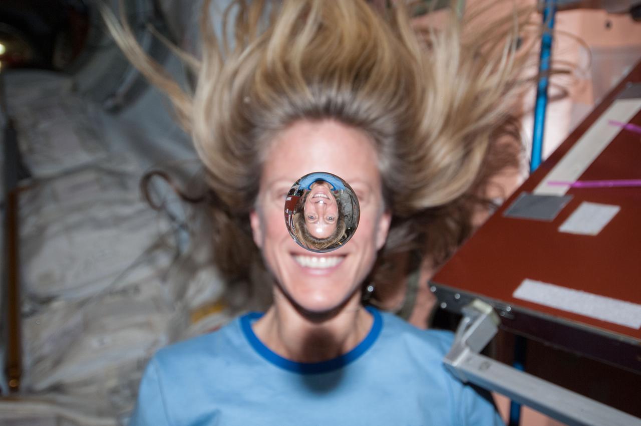
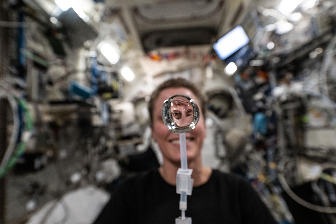
NASA astronaut Karen Nyberger, Expedition 36 flight engineer, watches a water bubble float freely between her and the camera, showing her image refracted in the droplet, while in the Node 1Unity module of the International Space Station.
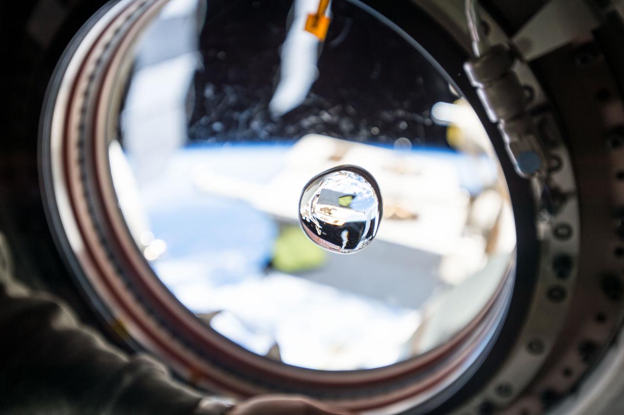
View of water bubble formed in front of the Japanese Experiment Module (JEM) window. The JEM Exposed Facility (JEF) is visible in the background through the window and reflected in the water. Scratches visible on the window.
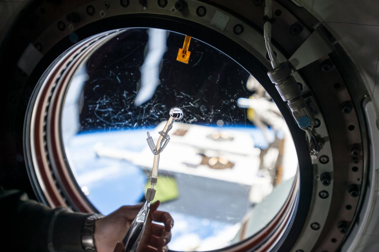
View of water bubble formed in front of the Japanese Experiment Module (JEM) window. The JEM Exposed Facility (JEF) is visible in the background through the window and reflected in the water. Scratches visible on the window.
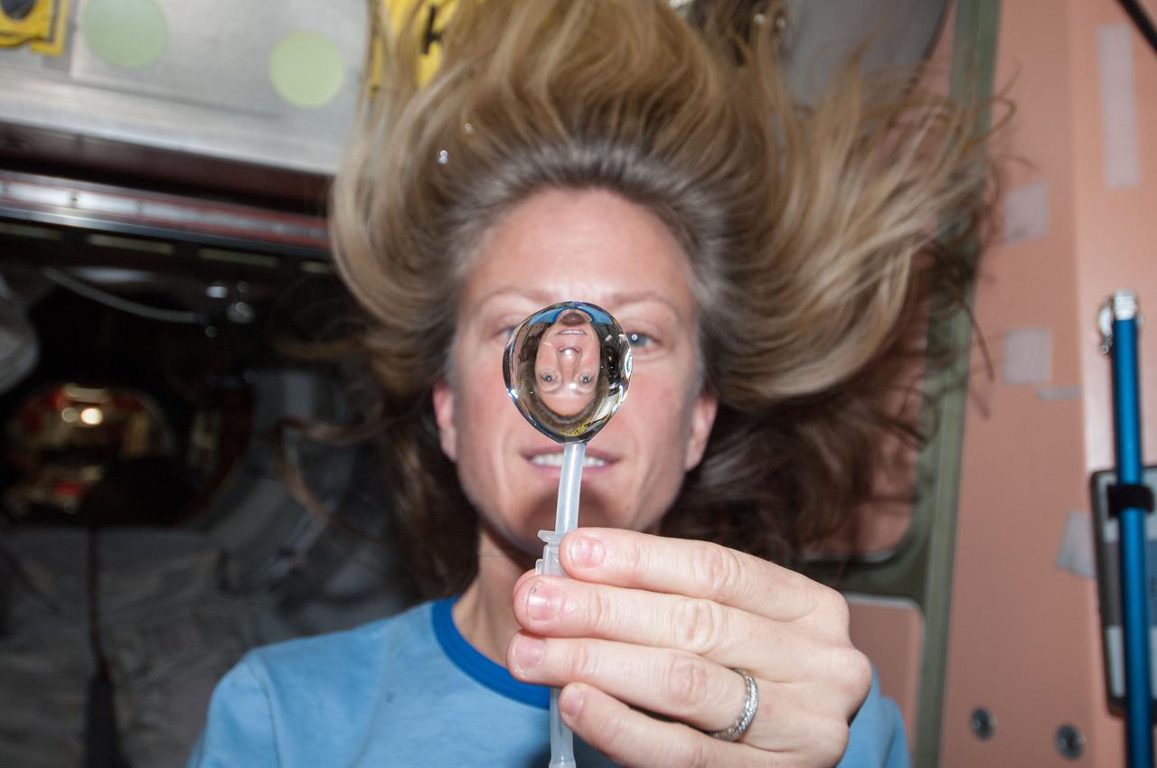
ISS036-E-018290 (12 July 2013) --- NASA astronaut Karen Nyberg, Expedition 36 flight engineer, squeezes a water bubble out of her beverage container, showing her image refracted, in the Unity node of the International Space Station.
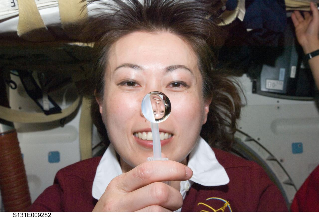
S131-E-009282 (12 April 2010) --- Japan Aerospace Exploration Agency (JAXA) astronaut Naoko Yamazaki, STS-131 mission specialist, squeezes a water bubble out of her beverage container, showing her image refracted, on the middeck of space shuttle Discovery while docked with the International Space Station.

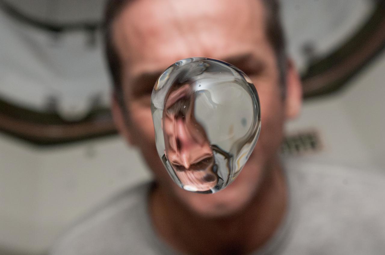
S131-E-009294 (12 April 2010) --- NASA astronaut Alan Poindexter, STS-131 commander, watches a water bubble float freely between him and the camera, showing his image refracted, on the middeck of space shuttle Discovery while docked with the International Space Station.
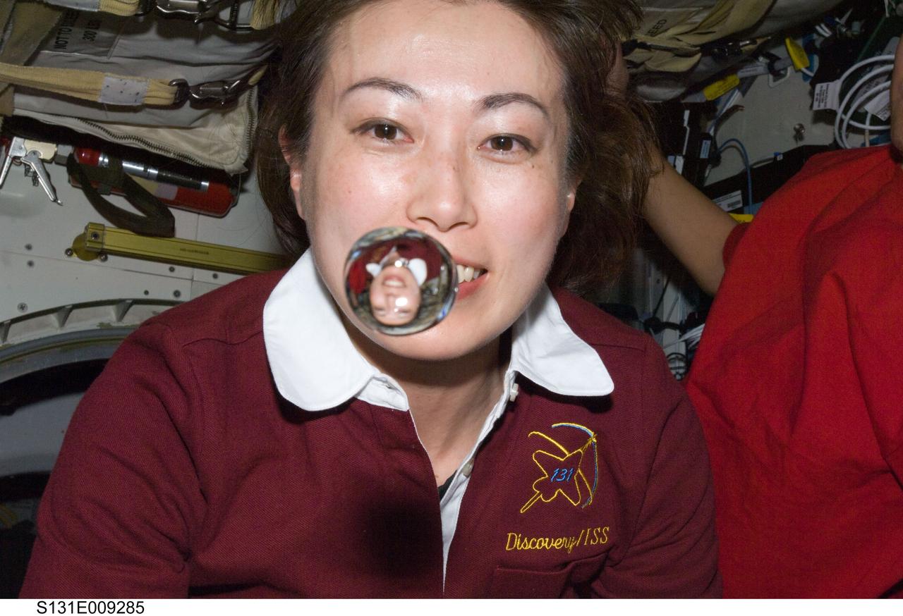
S131-E-009285 (12 April 2010) --- Japan Aerospace Exploration Agency (JAXA) astronaut Naoko Yamazaki, STS-131 mission specialist, watches a water bubble float freely between her and the camera, showing her image refracted, on the middeck of space shuttle Discovery while docked with the International Space Station.
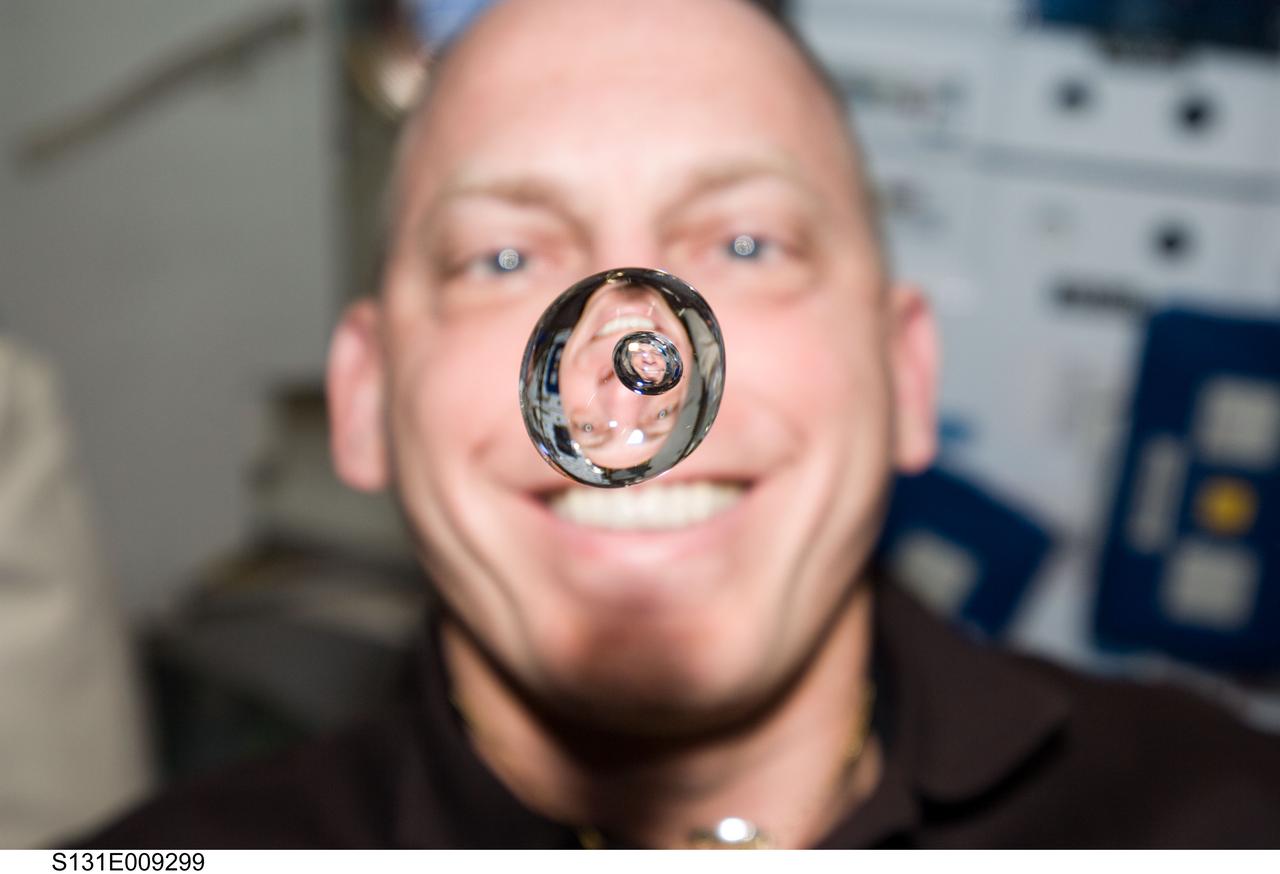
S131-E-009299 (12 April 2010) --- NASA astronaut Clayton Anderson, STS-131 mission specialist, watches a water bubble float freely between him and the camera, showing his image refracted, on the middeck of space shuttle Discovery while docked with the International Space Station.
ISS036-E-018302 (12 July 2013) --- NASA astronaut Chris Cassidy, Expedition 36 flight engineer, watches a water bubble float freely between him and the camera, showing his image refracted, in the Unity node of the International Space Station.
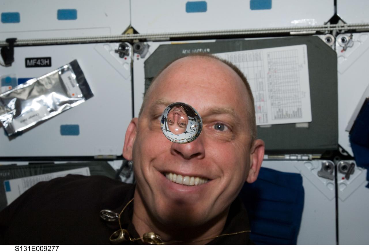
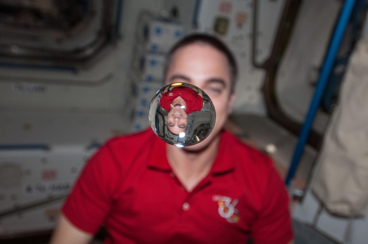
S131-E-009277 (12 April 2010) --- NASA astronaut Clayton Anderson, STS-131 mission specialist, watches a water bubble float freely between him and the camera, showing his image refracted, on the middeck of space shuttle Discovery while docked with the International Space Station.
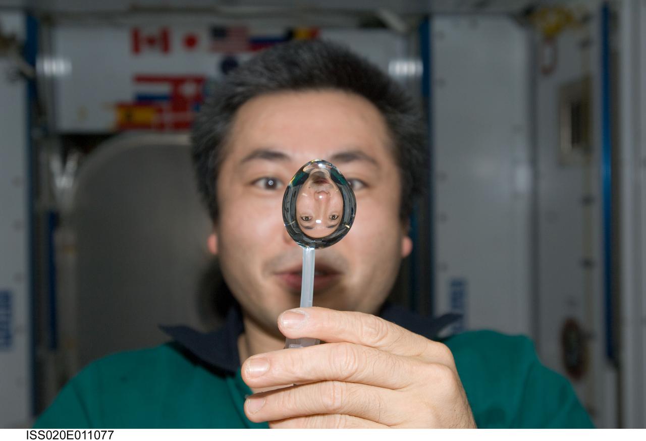
ISS020-E-011077 (16 June 2009) --- Japan Aerospace Exploration Agency (JAXA) astronaut Koichi Wakata, Expedition 20 flight engineer, squeezes a water bubble out of his beverage container, showing his image refracted, in the Harmony node of the International Space Station.
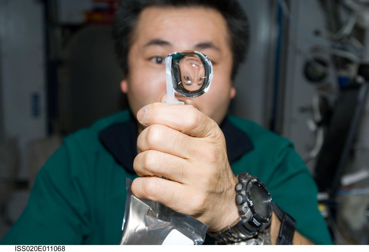
ISS020-E-011068 (16 June 2009) --- Japan Aerospace Exploration Agency (JAXA) astronaut Koichi Wakata, Expedition 20 flight engineer, squeezes a water bubble out of his beverage container, showing his image refracted, in the Harmony node of the International Space Station.
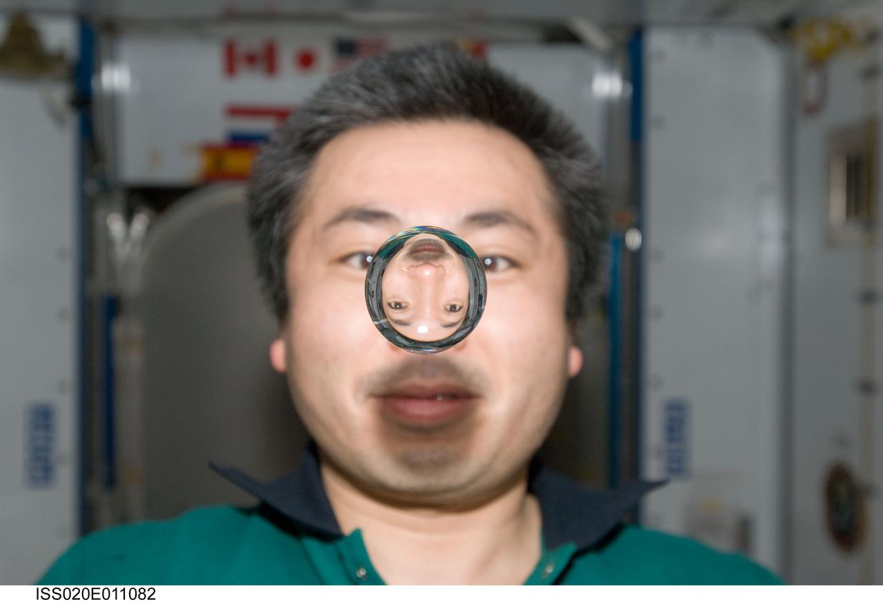
ISS020-E-011082 (16 June 2009) --- Japan Aerospace Exploration Agency (JAXA) astronaut Koichi Wakata, Expedition 20 flight engineer, watches a water bubble float freely between him and the camera, showing his image refracted, in the Harmony node of the International Space Station.
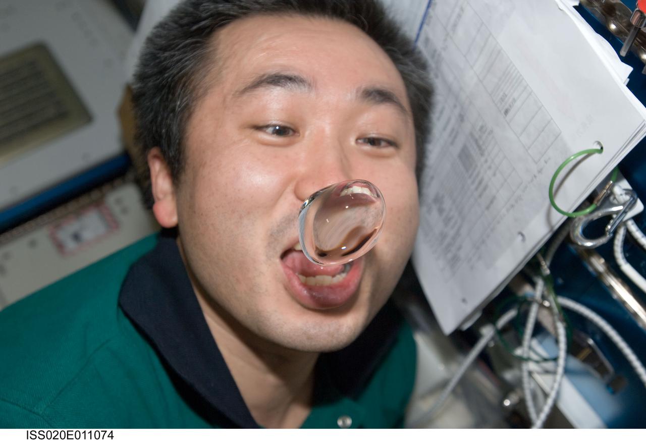
ISS020-E-011074 (16 June 2009) --- Japan Aerospace Exploration Agency (JAXA) astronaut Koichi Wakata, Expedition 20 flight engineer, attempts to catch a water bubble with his mouth in the Harmony node of the International Space Station.
View of Canadian Space Agency (CSA) Chris Hadfield,Expedition 34 Flight Engineer (FE),watching a water bubble float freely,showing his image refracted,in the Node 1. Photo was taken during Expedition 34.
ISS034-E-031855 (21 Jan. 2013) --- NASA astronaut Kevin Ford, Expedition 34 commander, watches a water bubble float freely between him and the camera, showing his image refracted, in the Unity node of the International Space Station.
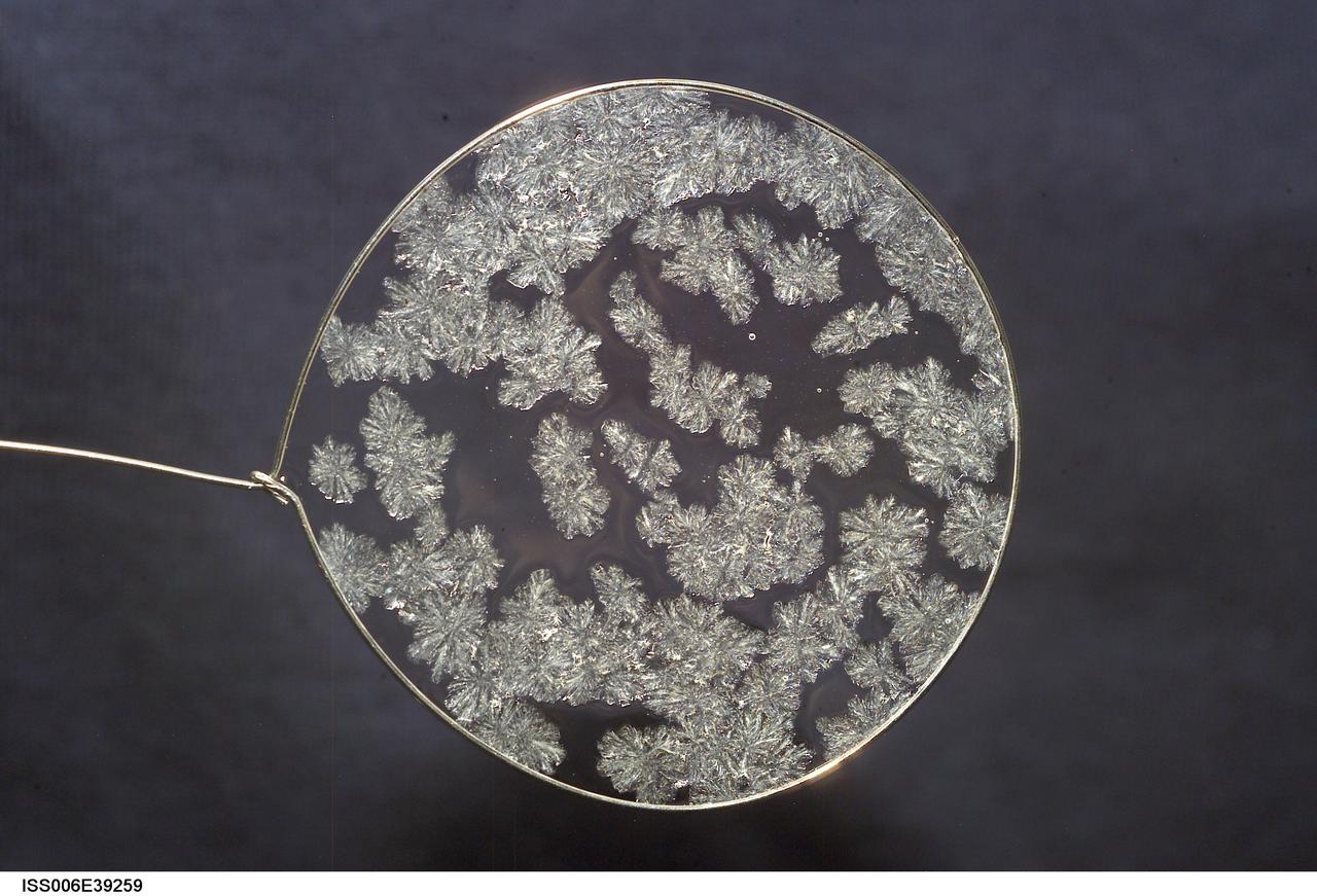
ISS006-E-39259 (14 March 2003) --- A view of sugar crystals in a water bubble within a 50-millimeter (mm) metal loop was photographed by an Expedition Six crewmember. The experiment took place in the Destiny laboratory on the International Space Station (ISS).
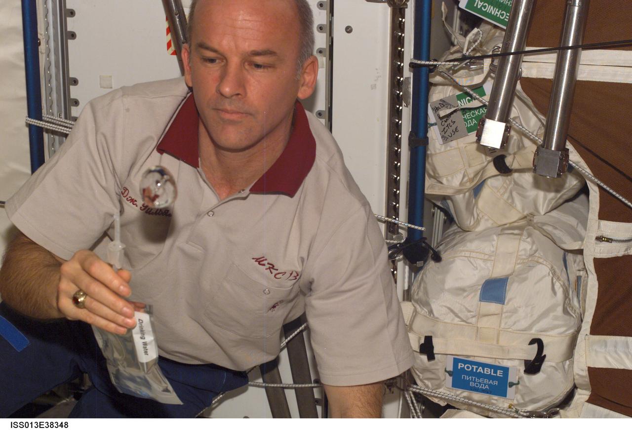
ISS013-E-38348 (18 June 2006) --- Astronaut Jeffrey N. Williams, Expedition 13 NASA space station science officer and flight engineer, watches a water bubble float freely while holding a container of water in the Destiny laboratory of the International Space Station.
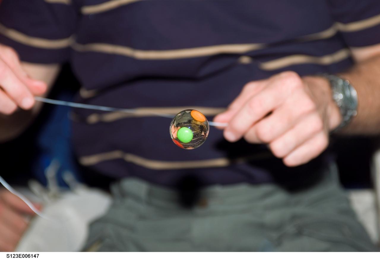
S123-E-006147 (14 March 2008) --- A water bubble with candy trapped inside floats freely on the middeck of Space Shuttle Endeavour while docked with the International Space Station. Astronaut Dominic Gorie (partially out of frame), STS-123 commander, holds a string near the bubble.
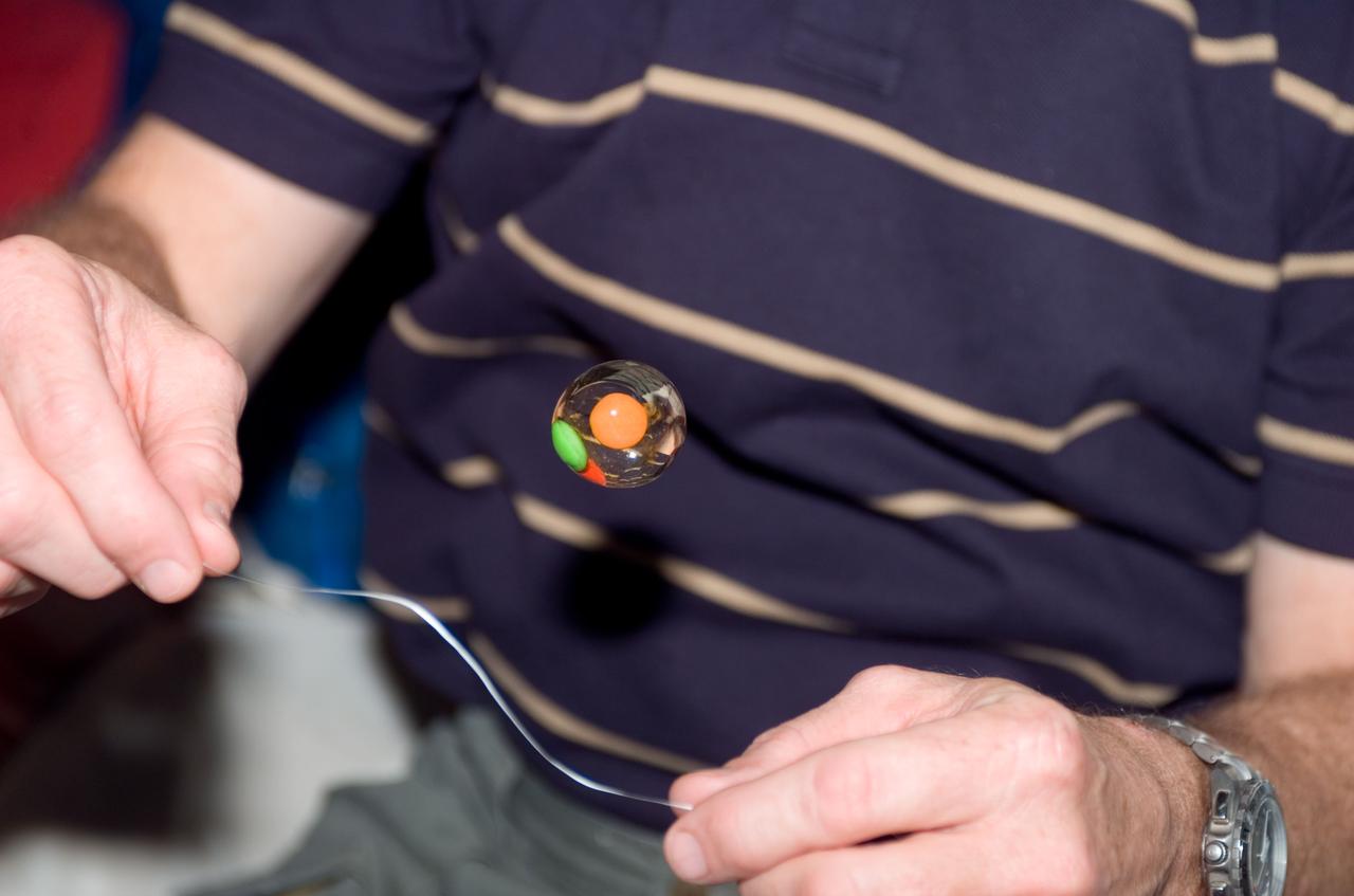
S123-E-006145 (14 March 2008) --- A water bubble with candy trapped inside floats freely on the middeck of Space Shuttle Endeavour while docked with the International Space Station. Astronaut Dominic Gorie (partially out of frame), STS-123 commander, holds a string near the bubble.
ISS034-E-031695 (21 Jan. 2013) --- Canadian Space Agency astronaut Chris Hadfield, Expedition 34 flight engineer, watches a water bubble float freely between him and the camera, showing his image refracted, in the Unity node of the International Space Station.
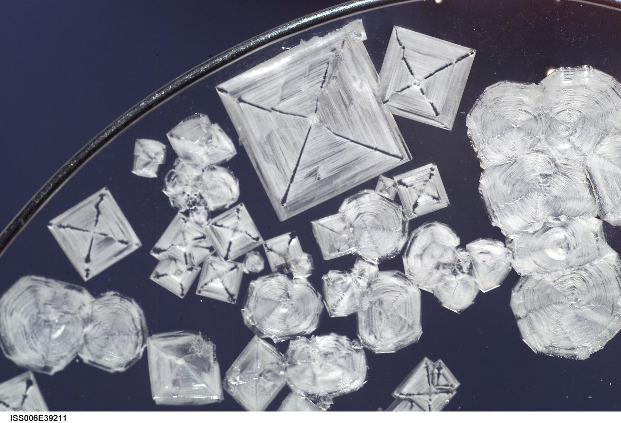
ISS006-E-39211 (13 March 2003) --- A close up view of sodium chloride crystals in a water bubble within a 50-millimeter metal loop was photographed by an Expedition Six crewmember. The experiment took place in the Destiny laboratory on the International Space Station (ISS).
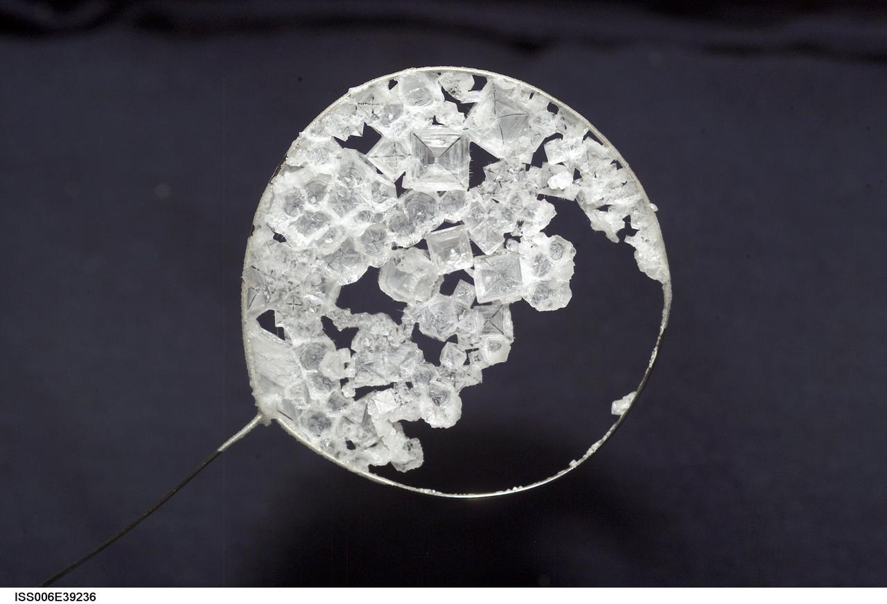
ISS006-E-39236 (14 March 2003) --- A view of sodium chloride crystals in a water bubble within a 50-millimeter metal loop was photographed by an Expedition Six crewmember. The experiment took place in the Destiny laboratory on the International Space Station (ISS).
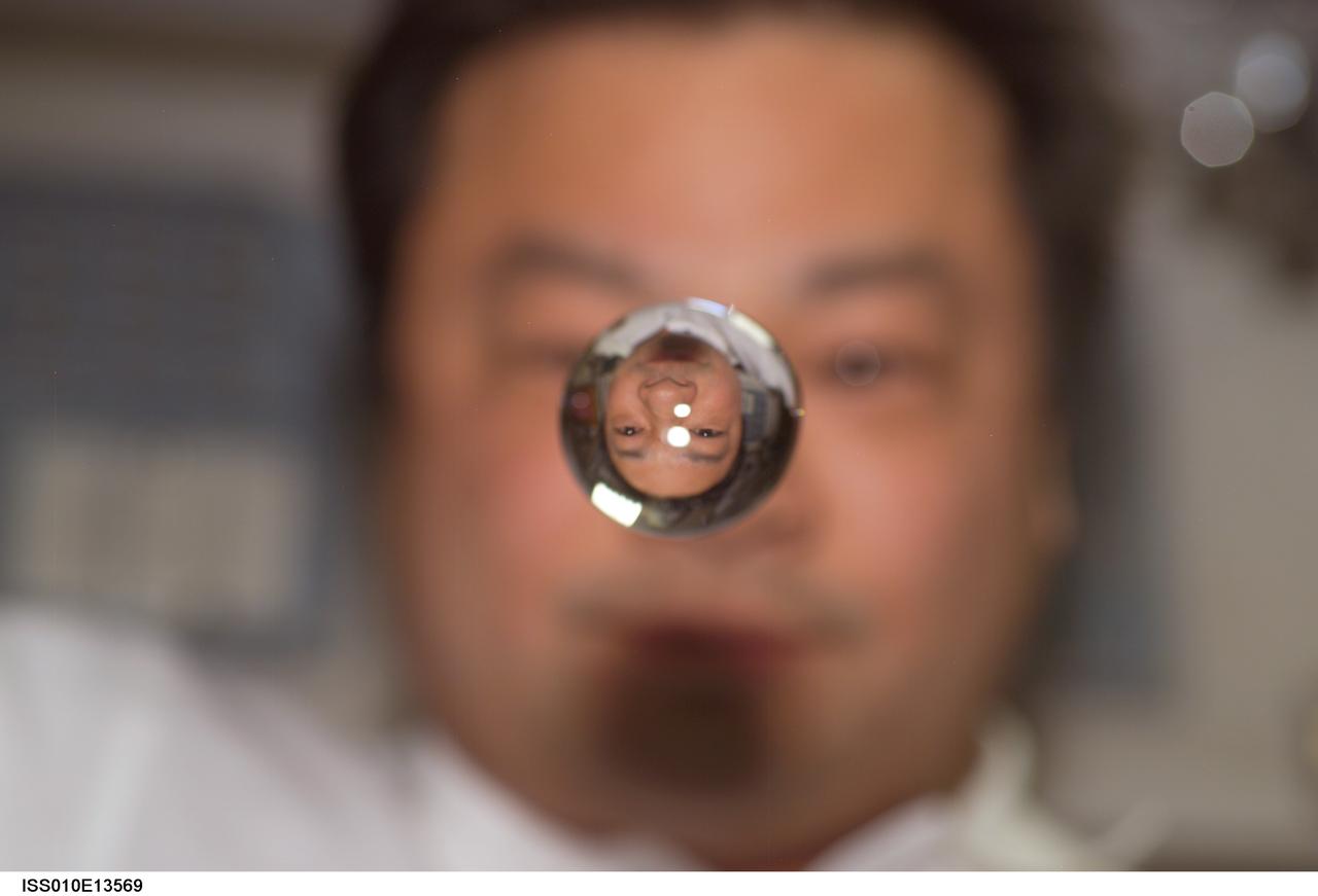
ISS010-E-13569 (15 January 2005) --- Astronaut Leroy Chiao, Expedition 10 commander and NASA ISS science officer, watches a water bubble float between him and the camera, showing his image refracted, on the International Space Station (ISS).
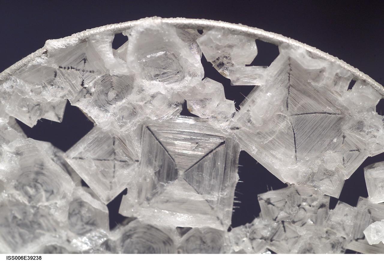
ISS006-E-39238 (14 March 2003) --- A close up view of sodium chloride crystals in a water bubble within a 50-millimeter metal loop was photographed by an Expedition Six crewmember. The experiment took place in the Destiny laboratory on the International Space Station (ISS).
ISS010-E-13562 (15 January 2005) --- Astronaut Leroy Chiao, Expedition 10 commander and NASA Space Station science officer, watches a water bubble float between himself and the camera in the Zvezda Service Module, showing his image refracted.
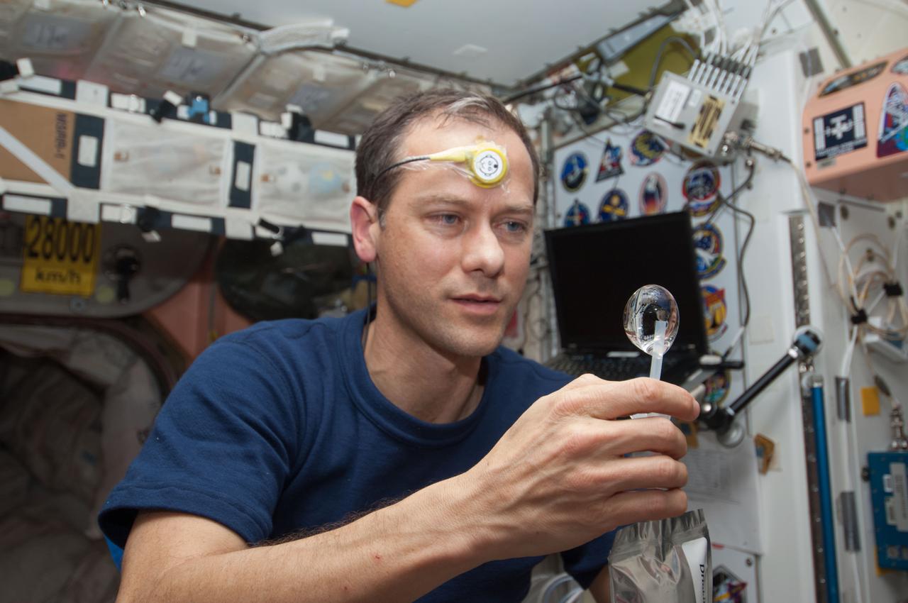
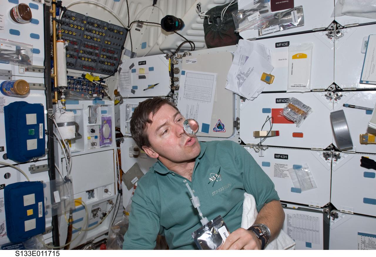
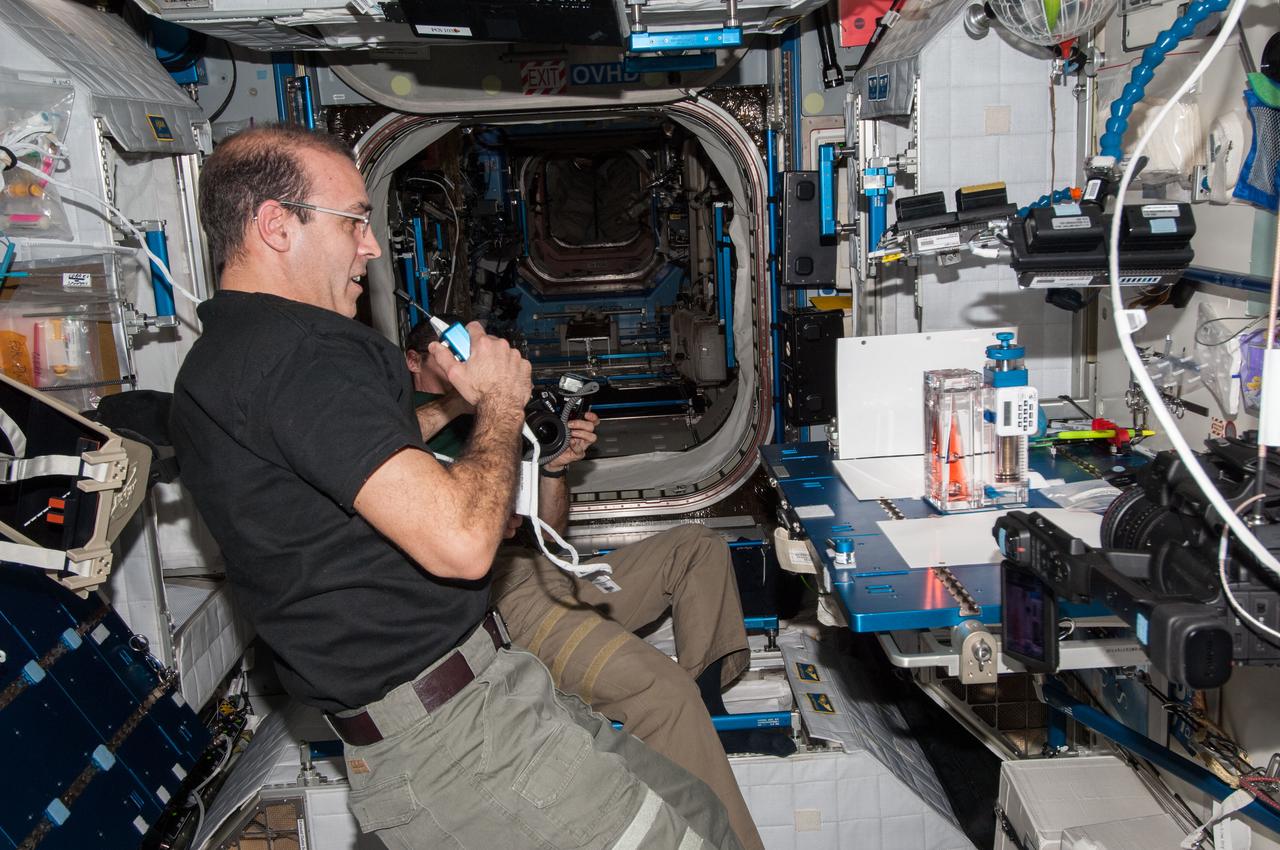
ISS034-E-031709 (21 Jan. 2013) --- NASA astronaut Tom Marshburn, Expedition 34 flight engineer, squeezes a water bubble out of his beverage container in the Unity node of the International Space Station. He is wearing a Drager Double Sensor on his forehead which is used on the Circadian Rhythms Experiment. This experiment examines the hypothesis that long-term spaceflights significantly affect the synchronization of the circadian rhythms in humans due to changes of a non-24 hour light-dark cycle.
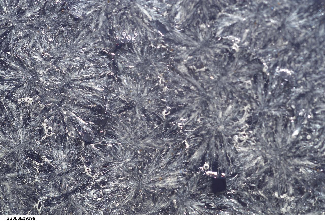
ISS006-E-39299 (15 March 2003) --- A close up view of sugar crystals in a water bubble within a 50-millimeter (mm) metal loop was photographed by an Expedition Six crewmember. The experiment took place in the Destiny laboratory on the International Space Station (ISS).
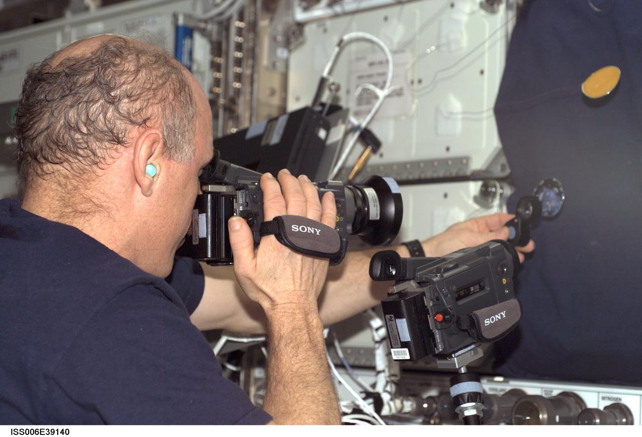
ISS006-E-39140 (12 March 2003) --- Astronaut Kenneth D. Bowersox, Expedition Six mission commander, photographs a water bubble within a 50-millimeter metal loop. The experiment took place in the Destiny laboratory on the International Space Station (ISS).
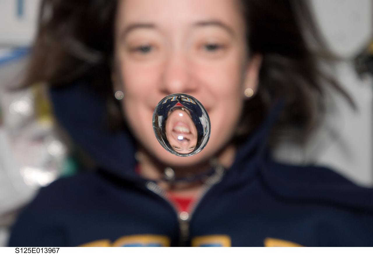
View of STS-125 Mission Specialist 2 (MS2) Megan McArthur posing for a photo on the middeck. A water bubble, showing a reflection of McArthur, floats in front of her.
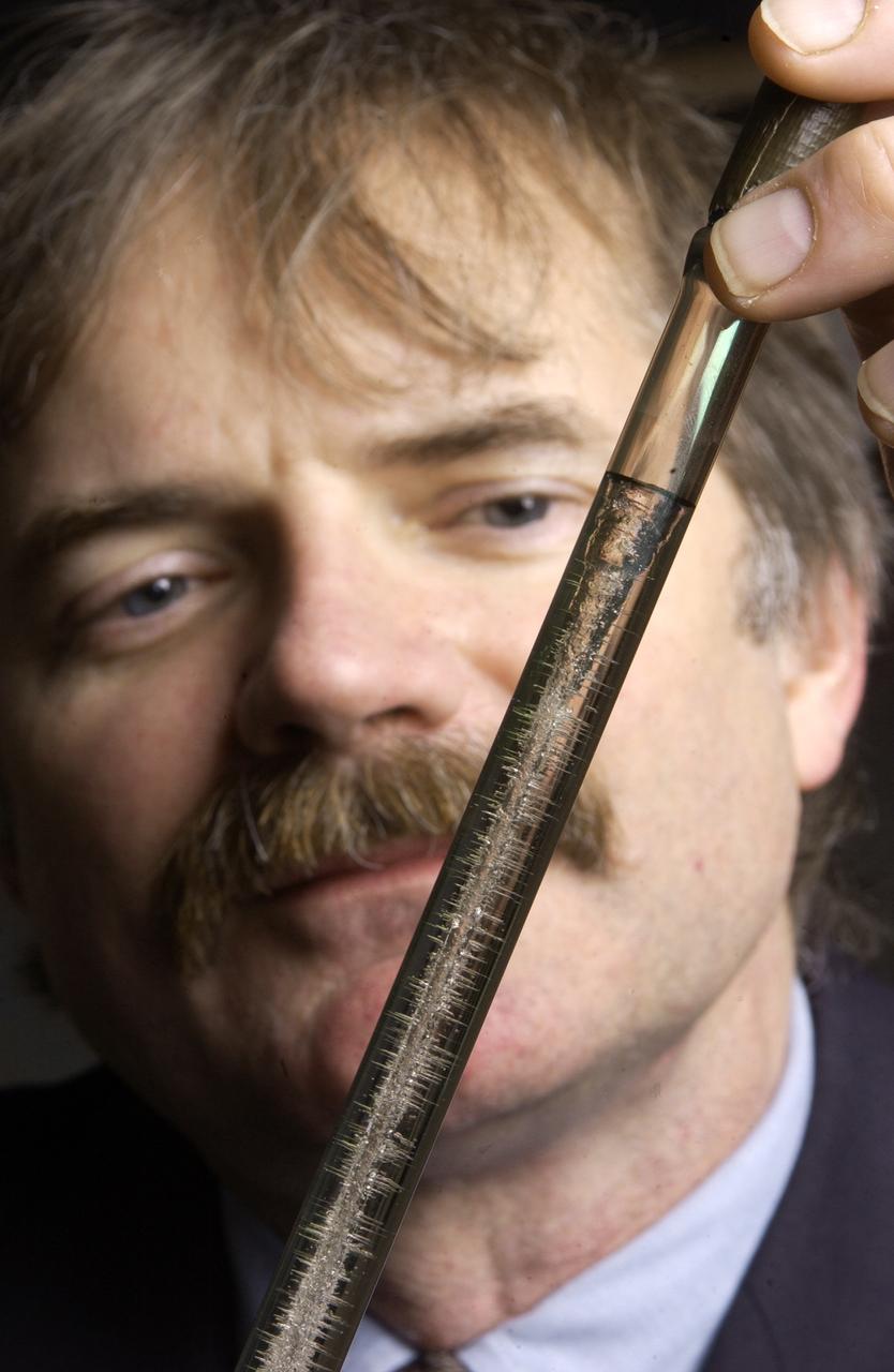
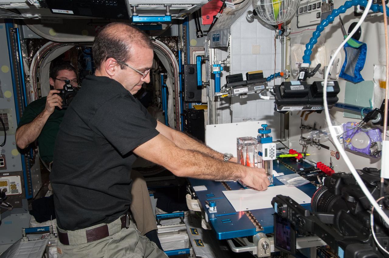
On Earth when scientists melt metals, bubbles that form in the molten material can rise to the surface, pop and disappear. In microgravity -- the near-weightless environment created as the International Space Station orbits Earth -- the lighter bubbles do not rise and disappear. Prior space experiments have shown that bubbles often become trapped in the final metal or crystal sample -similar to the bubbles trapped in this sample. In the solid, these bubbles, or porosity, are defects that diminish both the material's strength and usefulness. The Pore Formation and Mobility Investigation will melt samples of a transparent modeling material, succinonitrile and succinonitrile water mixtures, shown here in an ampoule being examined by Dr. Richard Grugel, the principal investigator for the experiment at NASA's Marshall Space Flight Center in Huntsville, Ala. As the samples are processed in space, Grugel will be able to observe how bubbles form in the samples and study their movements and interactions.
iss070e133764 (April 1, 2024) --- Expedition 70 Flght Engineer and NASA astronaut Loral O'Hara's image is refracted in a water bubble she squeezed from a drinking bag aboard the International Space Station's Kibo laboratory module.
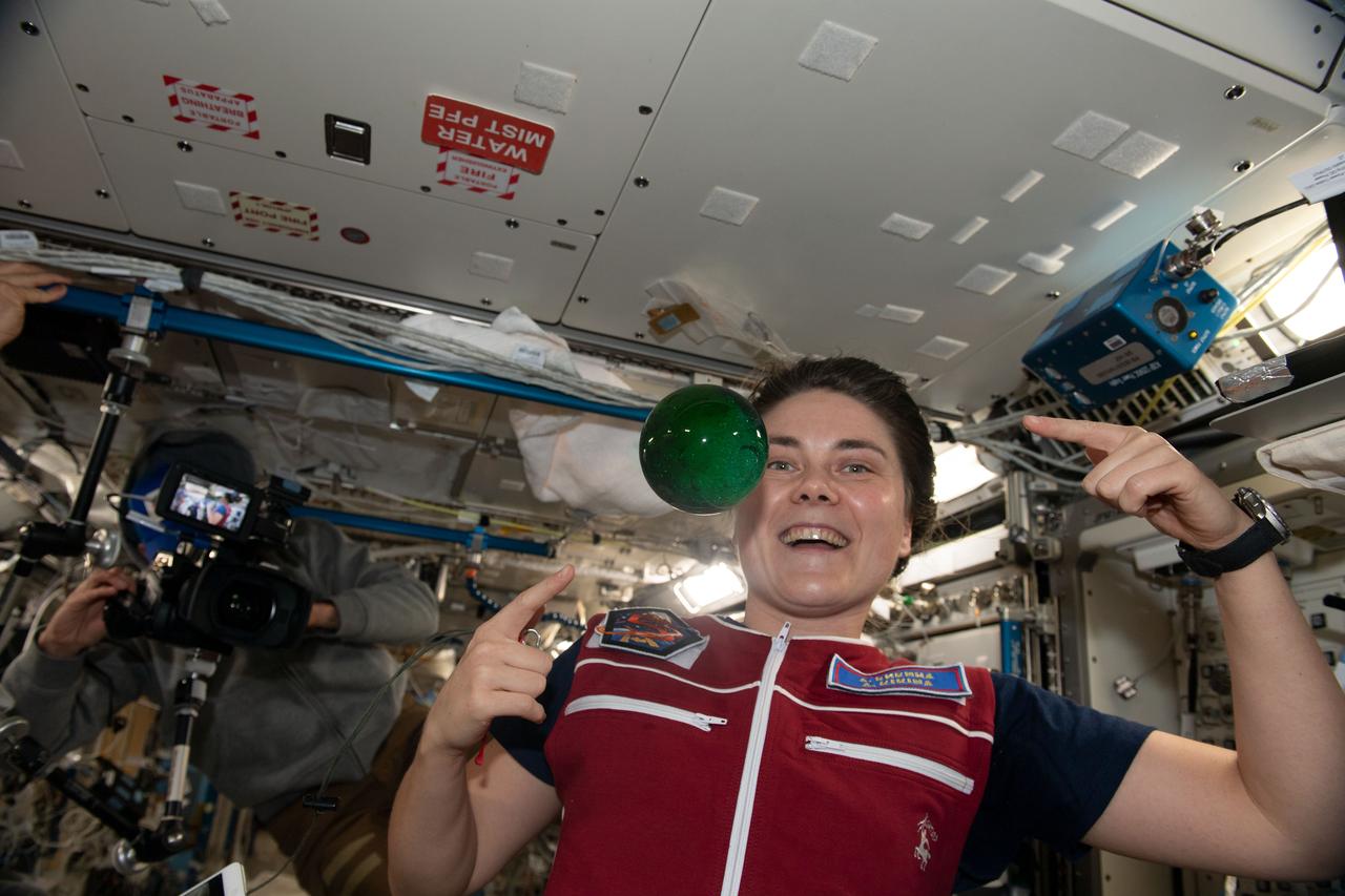
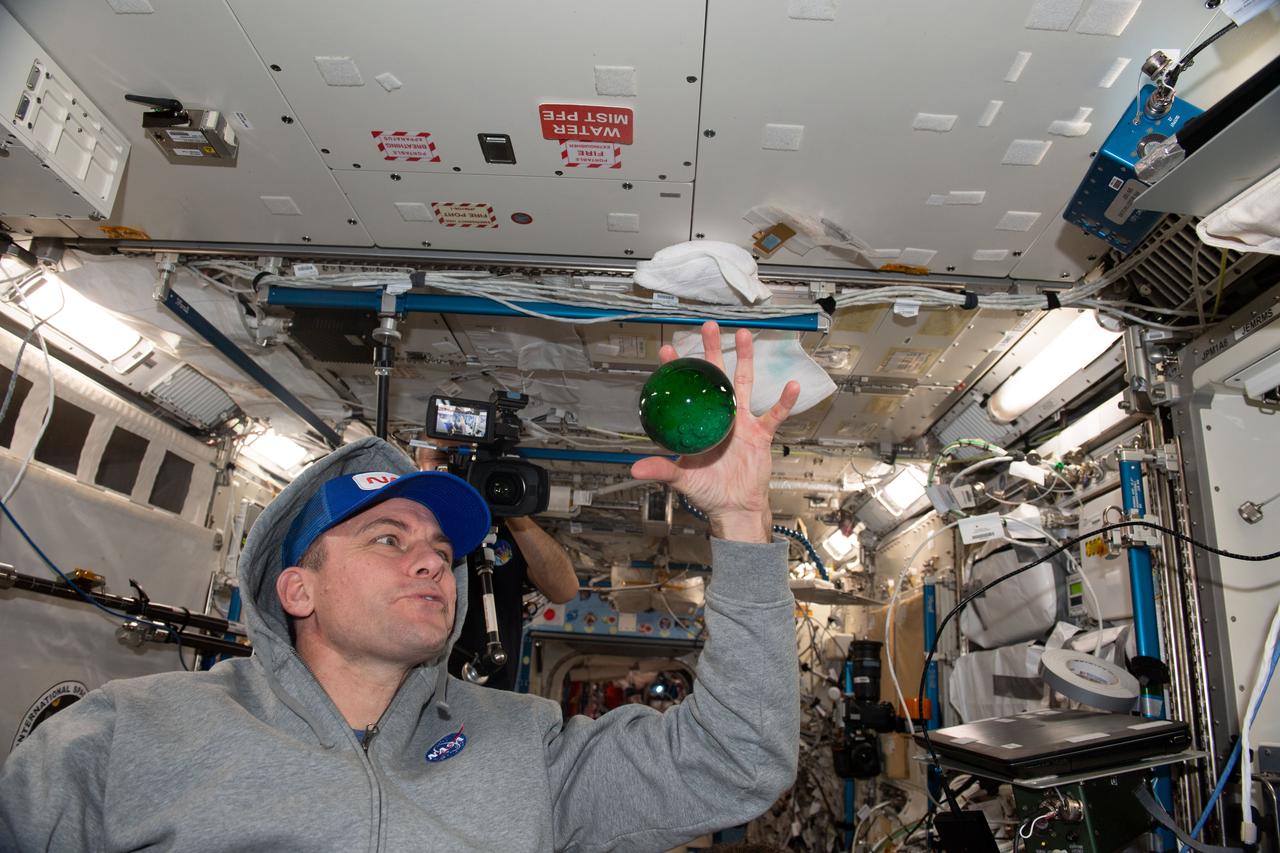
iss068e051617 (Feb. 12, 2023) --- Roscosmos cosmonaut and Expedition 68 Flight Engineer Anna Kikina plays with a sphere of water flying in microgravity that has been dyed with green food coloring and is bubbling due to an antacid that was placed inside.
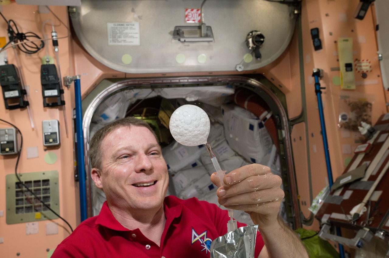
ISS043E276537 (05/31/2015) --- Expedition 43 Commander and NASA astronaut Terry Virts creates a sphere of bubbles in the station’s microgravity environment using drinking water and an antacid tablet.
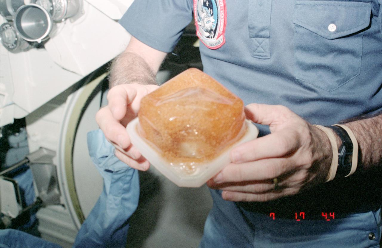
STS009-126-456 (28 Nov 1983) --- Water and coffee in beverage container during STS-9 flight. An extra amount of hydrogen in the H2O is believed to be the reason for the bubbling, distended effect in the container.
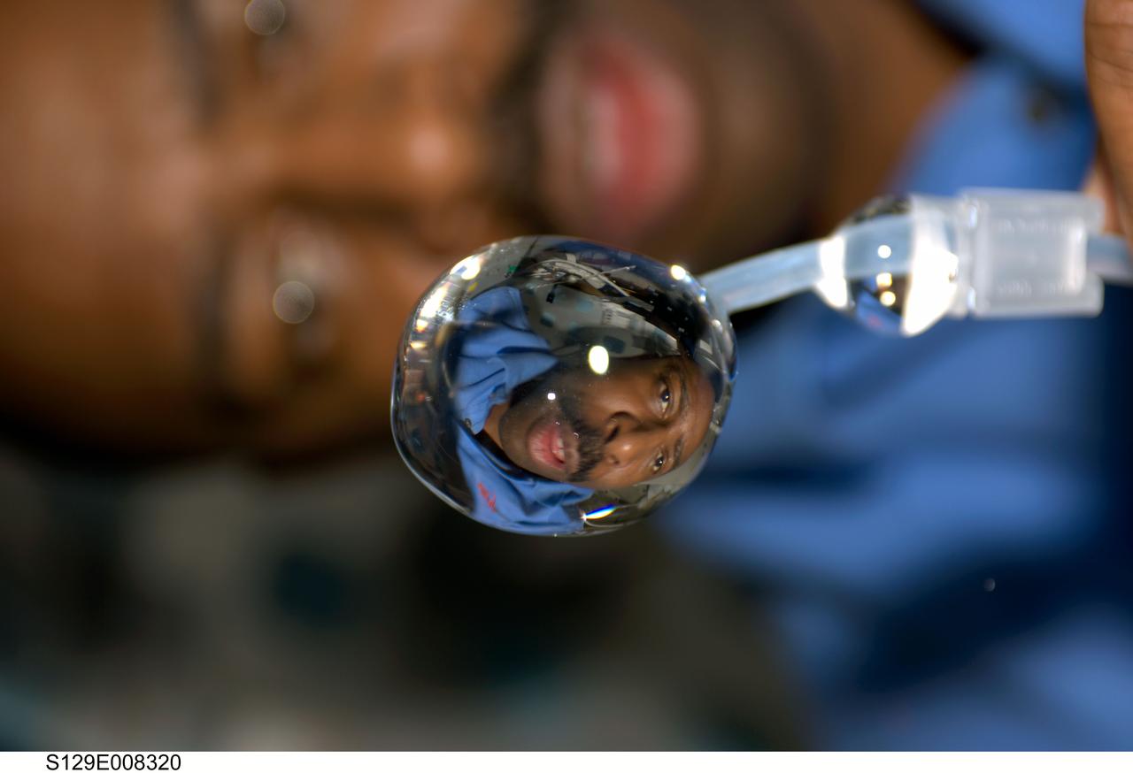
S129-E-008320 (24 Nov. 2009) --- This close-up view of a water bubble floating freely on the middeck of space shuttle Atlantis shows a refracted image of astronaut Leland Melvin, STS-129 mission specialist.
iss068e051621 (Feb. 12, 2023) --- NASA astronaut and Expedition 68 Flight Engineer Josh Cassada plays with a sphere of water flying in microgravity that has been dyed with green food coloring and is bubbling due to an antacid that was placed inside.
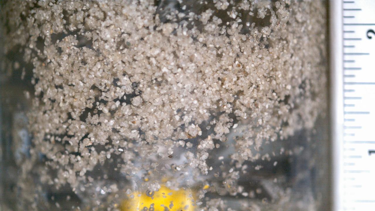
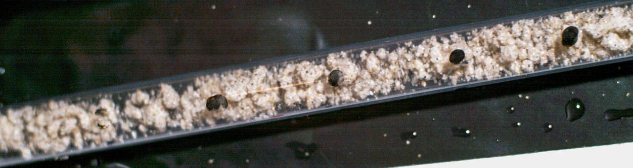
jsc2022e072959 (9/16/2022) --- Coarse hydrophobic sand is mixed for 25 seconds with water and air. Researchers observe a decent amount of agglomerates (air bubbles) covered by hydrophobic sand particles flowing in the water body. There are also free sand particles floating around. Catastrophic Post-Wildfire Mudflows studies the formation and stability of this bubble-sand structure in microgravity. A better understanding of these phenomena could improve the understanding, modeling, and predicting of mudflows and support development of innovative solutions to prevent catastrophic post-fire events. Image courtesy of the UCSD Geo-Micromechanics Research Group.
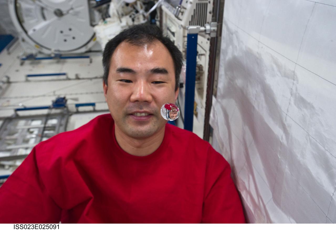
ISS023-E-025091 (19 April 2010) --- Japan Aerospace Exploration Agency (JAXA) astronaut Soichi Noguchi, Expedition 23 flight engineer, watches a water bubble float freely between him and the camera, showing his image refracted, in the Kibo laboratory of the International Space Station.
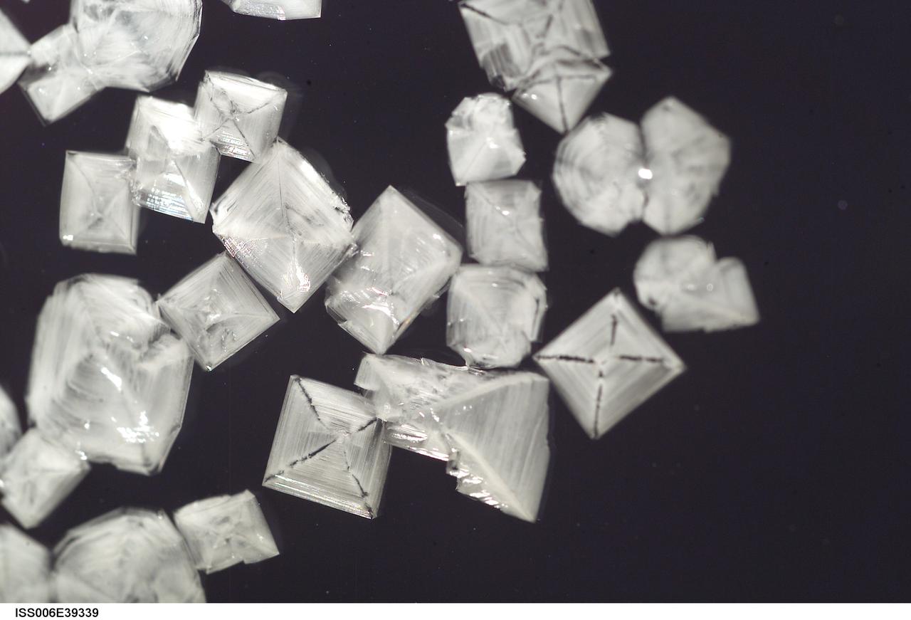
ISS006-E-39339 (15 March 2003) --- A close up view of sodium chloride crystals in a water bubble within a 50-millimeter metal loop was photographed by an Expedition Six crewmember. The experiment took place in the Destiny laboratory on the International Space Station (ISS).
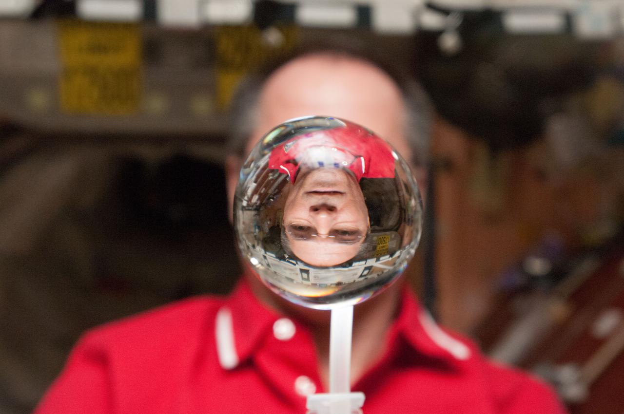
ISS031-E-143936 (24 June 2012) --- NASA astronaut Joe Acaba, Expedition 31 flight engineer, watches a water bubble float freely between him and the camera, showing his image refracted, on the International Space Station.
S133-E-011715 (7 March 2011) --- NASA astronaut Michael Barratt, STS-133 mission specialist, watches a water bubble float freely near him on the middeck of space shuttle Discovery during flight day 12 activities. Photo credit: NASA or National Aeronautics and Space Administration
iss068e006271 (Oct. 1, 2022) --- NASA astronaut and Expedition 68 Flight Engineer Jessica Watkins has fun with fluid physics as she observes the behavior of a free-flying water bubble inside the International Space Station's Kibo laboratory module.
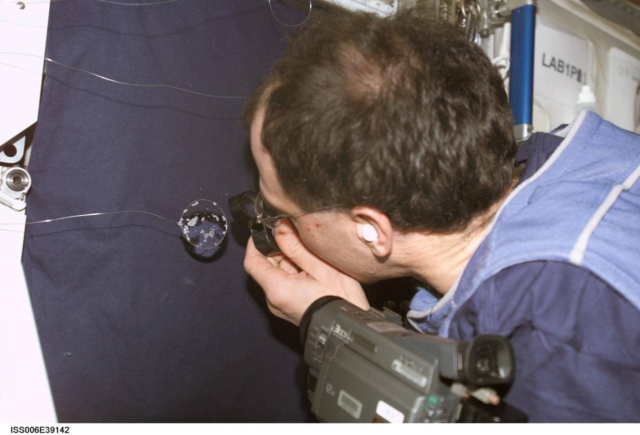
ISS006-E-39142 (12 March 2003) --- Astronaut Donald R. Pettit, Expedition Six NASA ISS science officer, looks closely at a water bubble within a 50-millimeter metal loop. The experiment took place in the Destiny laboratory on the International Space Station (ISS).
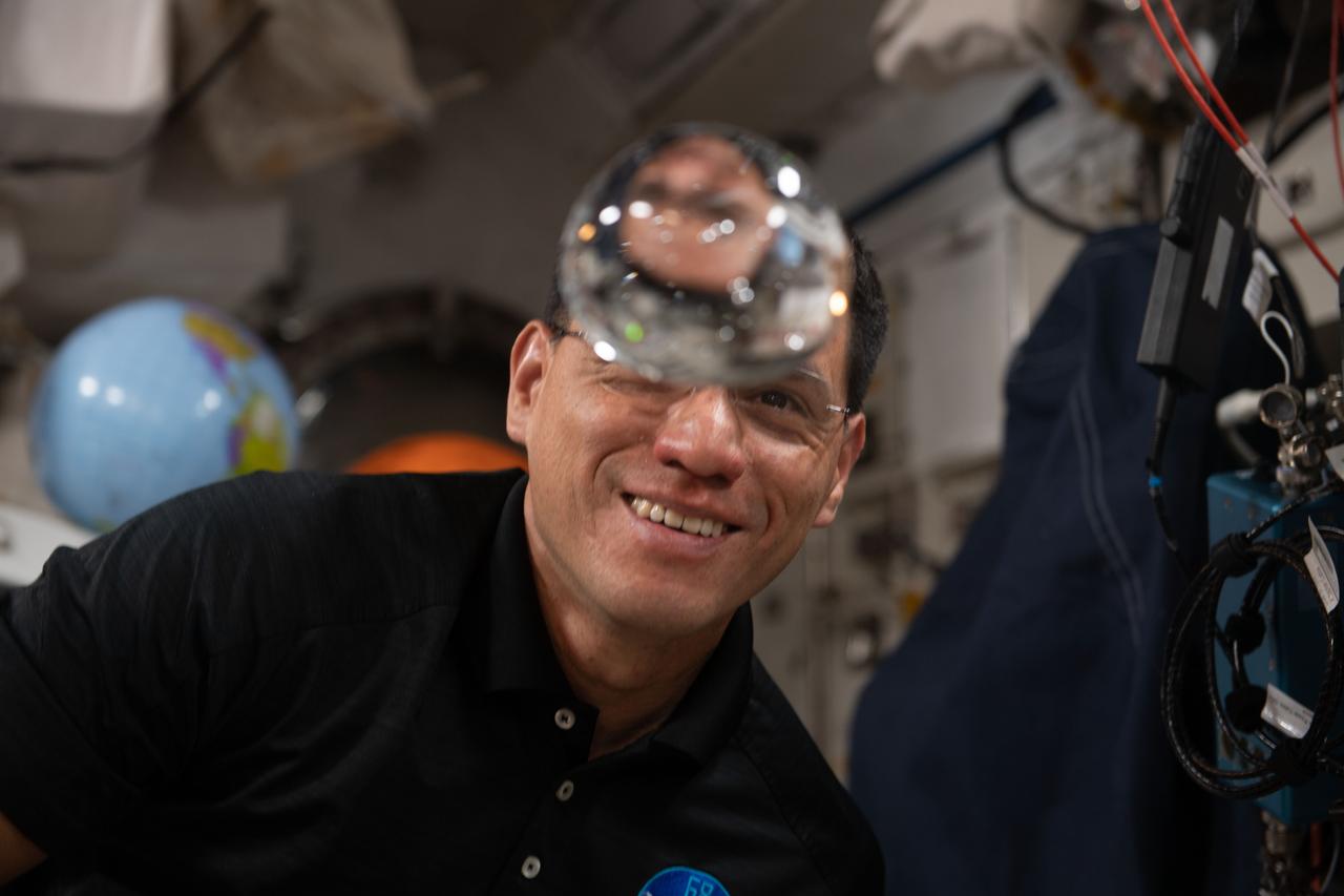
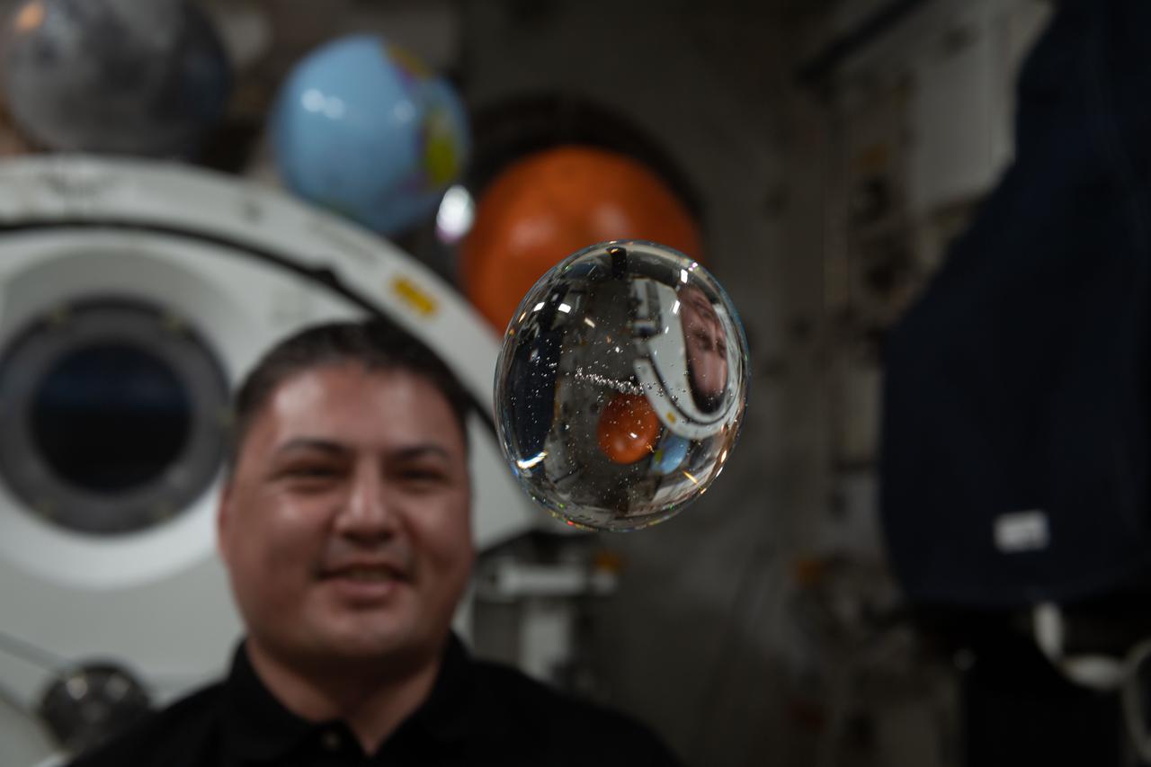
iss068e006386 (Oct. 1, 2022) --- NASA astronaut and Expedition 68 Flight Engineer Frank Rubio has fun with fluid physics as he observes the behavior of a free-flying water bubble inside the International Space Station's Kibo laboratory module.

ISS031-E-143872 (24 June 2012) --- European Space Agency astronaut Andre Kuipers, Expedition 31 flight engineer, squeezes a water bubble out of his beverage container, showing his image refracted and reflected, on the International Space Station.
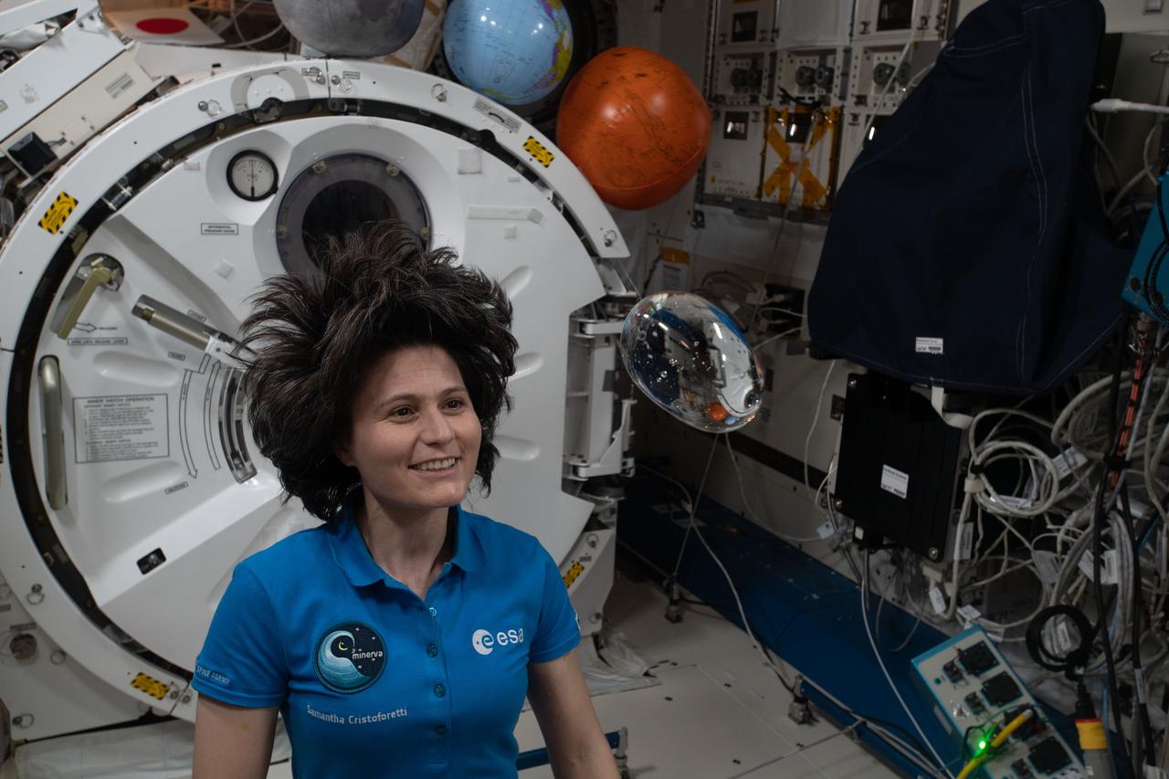
iss068e005884 (Oct. 1, 2022) --- ESA (European Space Agency) astronaut and Expedition 68 Flight Engineer Samantha Cristoforetti has fun with fluid physics as she observes the behavior of a free-flying water bubble inside the International Space Station's Kibo laboratory module.
ISS031-E-143875 (24 June 2012) --- European Space Agency astronaut Andre Kuipers, Expedition 31 flight engineer, watches a water bubble float freely between him and the camera, showing his image refracted and reflected, on the International Space Station.
iss068e006306 (Oct. 1, 2022) --- NASA astronaut and Expedition 68 Flight Engineer Kjell Lindgren has fun with fluid physics as he observes the behavior of a free-flying water bubble inside the International Space Station's Kibo laboratory module.
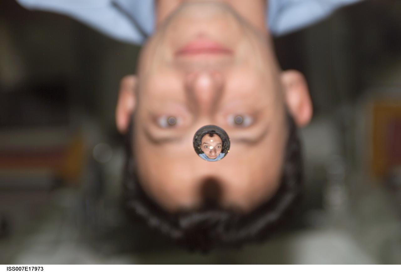
ISS007-E-17985 (2003) --- Astronaut Edward T. Lu, Expedition 7 NASA ISS science officer and flight engineer, watches a water bubble float between him and the camera, showing his image refracted, on the International Space Station (ISS).
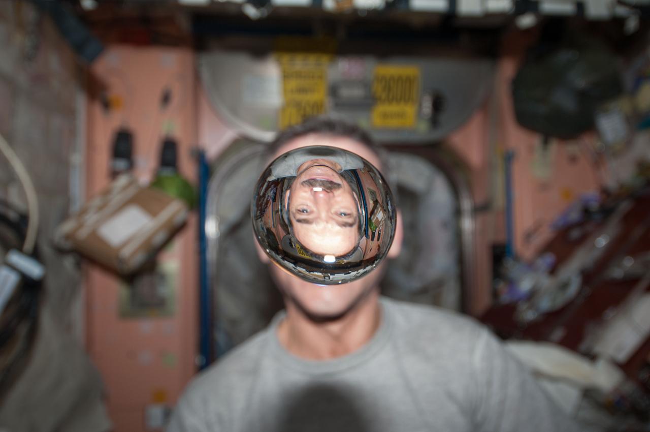
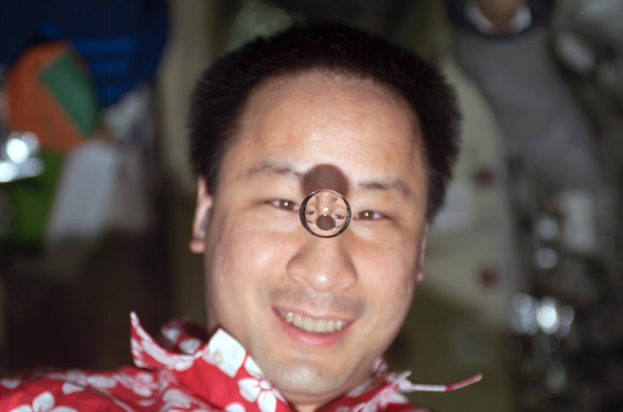
ISS007-E-17973 (25 October 2003) --- European Space Agency (ESA) astronaut Pedro Duque of Spain watches a water bubble float between him and the camera, showing his image refracted, on the International Space Station (ISS).
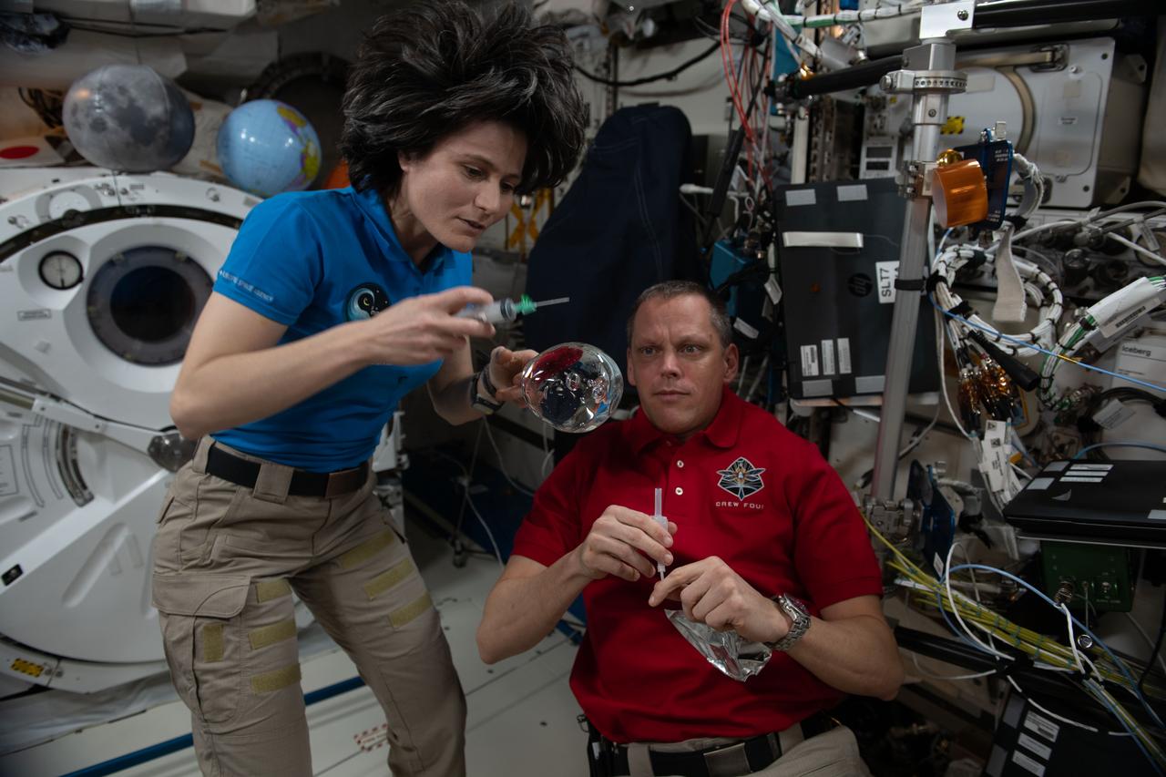
iss068e006399 (Oct. 1, 2022) --- Expedition 68 Flight Engineers Samantha Cristoforetti of ESA (European Space Agency) and Bob Hines of NASA have fun with fluid physics as they observe the behavior of a free-flying water bubble inside the International Space Station's Kibo laboratory module.
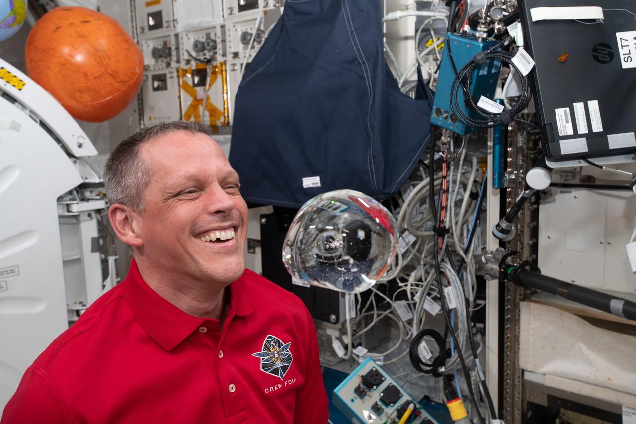
iss068e005874 (Oct. 1, 2022) --- NASA astronaut and Expedition 68 Flight Engineer Bob Hines has fun with fluid physics as he observes the behavior of a free-flying water bubble inside the International Space Station's Kibo laboratory module.
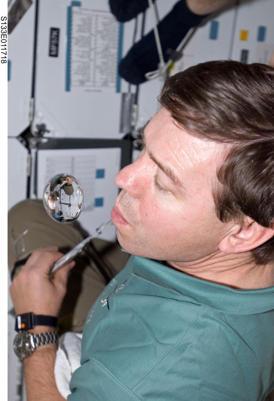
S133-E-011718 (7 March 2011) --- NASA astronaut Michael Barratt, STS-133 mission specialist, watches a water bubble float freely near him on the middeck of space shuttle Discovery during flight day 12 activities. Photo credit: NASA or National Aeronautics and Space Administration
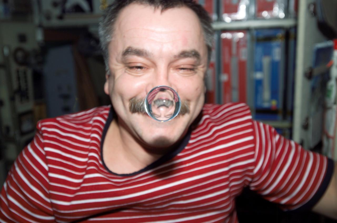
ISS014-E-11798 (14 Jan. 2007) --- Cosmonaut Mikhail Tyurin, Expedition 14 flight engineer representing Russia's Federal Space Agency, watches a water bubble float between him and the camera, showing his image refracted, in the Zvezda Service Module of the International Space Station.
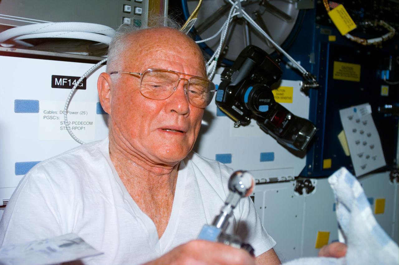
STS095-E-5195 (31 Oct. 1998) --- U.S. Sen. John H. Glenn Jr., STS-95 payload specialist, is pictured with a water dispenser on Discovery's middeck during Flight Day two activity. The photo was taken with an electronic still camera (ESC) at 07:09:33 GMT, Oct. 31.

jsc2022e072961 (9/16/2022) --- Researchers drop a water droplet on the flat surface of hydrophobic fine sand. The water droplet has a contact angle of 120 degrees at the three-phase interface. The water droplet stands up and has a more rounded shape than a flattened shape compared to normal hydrophilic sand. Catastrophic Post-Wildfire Mudflows studies the formation and stability of this bubble-sand structure in microgravity. A better understanding of these phenomena could improve the understanding, modeling, and predicting of mudflows and support development of innovative solutions to prevent catastrophic post-fire events. Image courtesy of the UCSD Geo-Micromechanics Research Group.
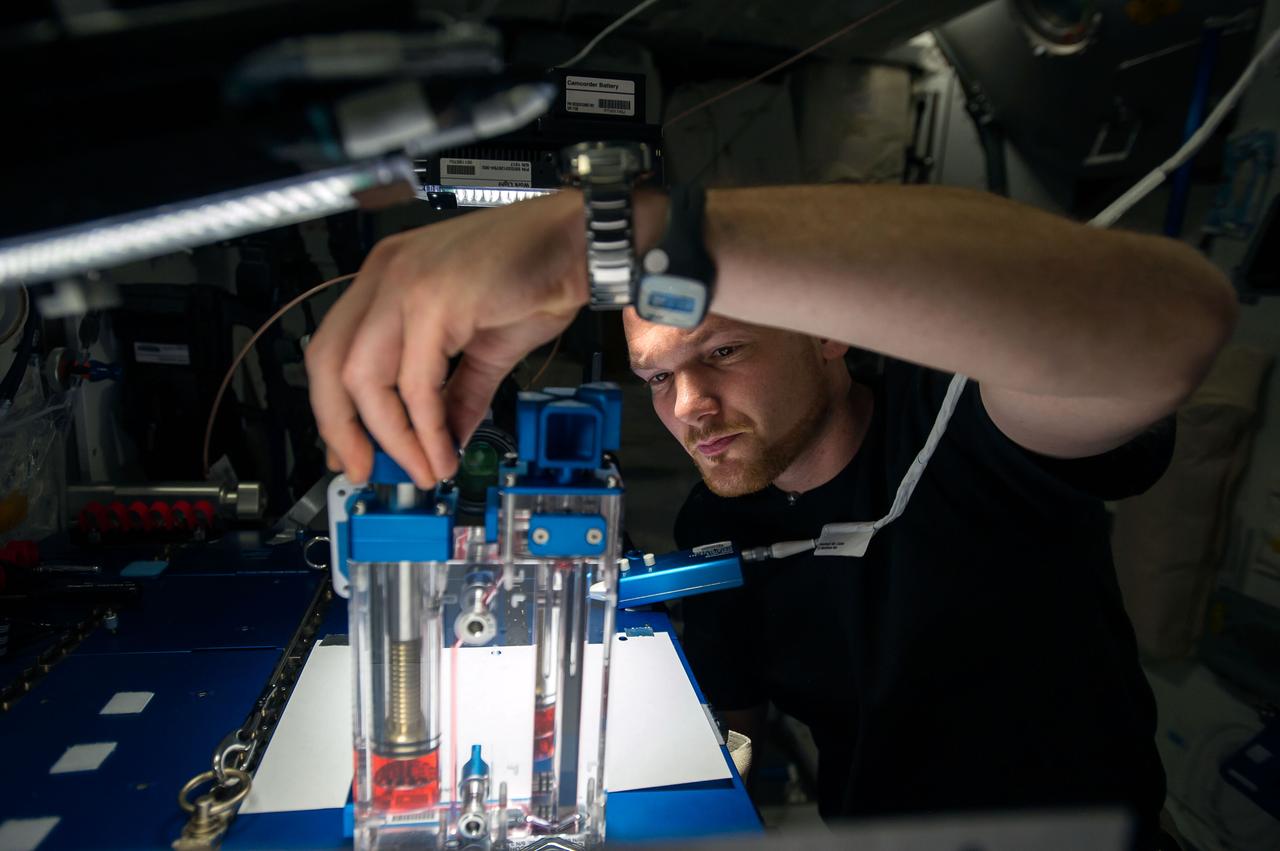
ISS040-E-015536 (19 June 2014) --- European Space Agency astronaut Alexander Gerst, Expedition 40 flight engineer, conducts a session with the Capillary Flow Experiment (CFE-2) in the Harmony node of the International Space Station. CFE is a suite of fluid physics experiments that investigate how fluids behave in microgravity which could benefit water and fuel delivery systems on future spacecraft. Scientists designed the CFE-2 to study properties of fluids and bubbles inside containers with a specific 3-D geometry.
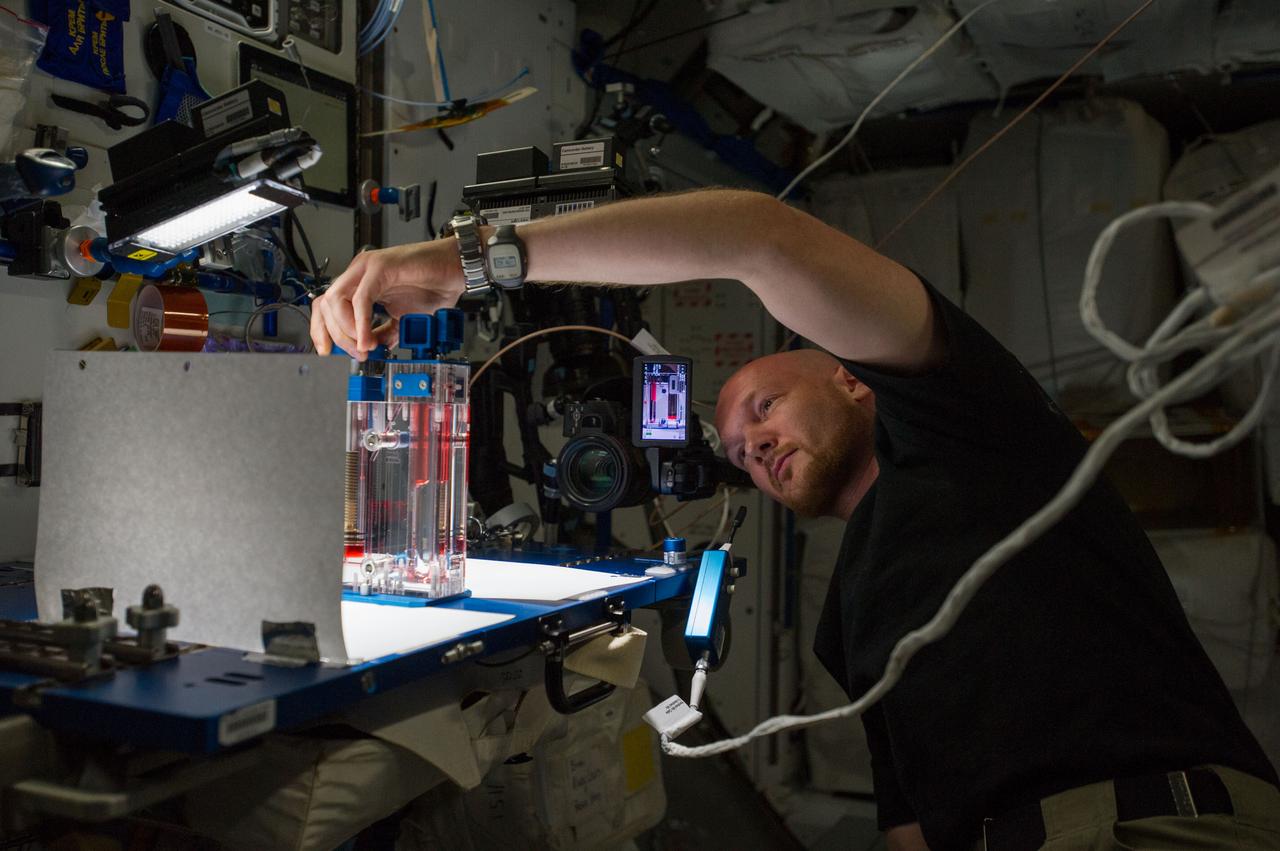
ISS040-E-015545 (19 June 2014) --- European Space Agency astronaut Alexander Gerst, Expedition 40 flight engineer, conducts a session with the Capillary Flow Experiment (CFE-2) in the Harmony node of the International Space Station. CFE is a suite of fluid physics experiments that investigate how fluids behave in microgravity which could benefit water and fuel delivery systems on future spacecraft. Scientists designed the CFE-2 to study properties of fluids and bubbles inside containers with a specific 3-D geometry.
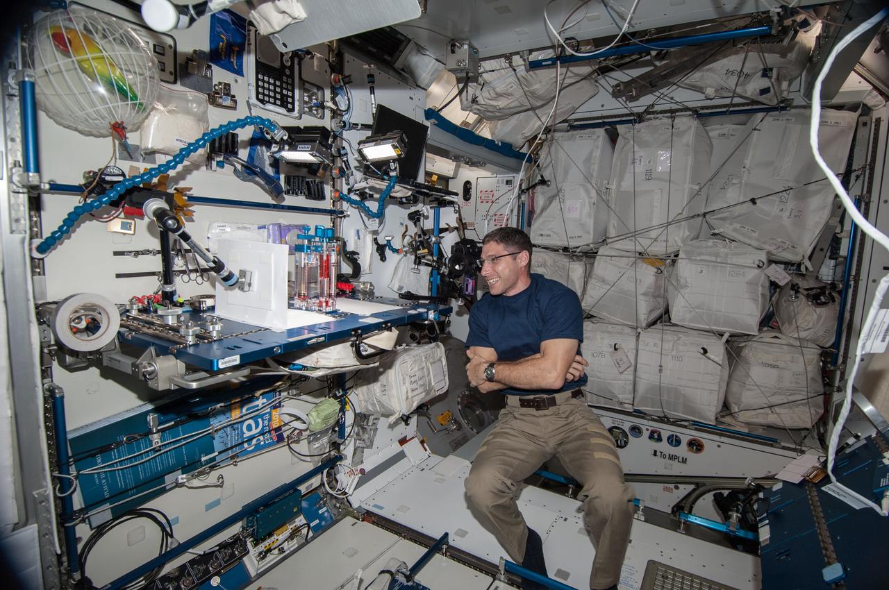
ISS038-E-005962 (19 Nov. 2013) --- NASA astronaut Michael Hopkins, Expedition 38 flight engineer, conducts a session with the Capillary Flow Experiment (CFE-2) in the Harmony node of the International Space Station. CFE is a suite of fluid physics experiments that investigate how fluids behave in microgravity which could benefit water and fuel delivery systems on future spacecraft. Scientists designed the Capillary Flow Experiment-2 to study properties of fluids and bubbles inside containers with a specific 3-D geometry.
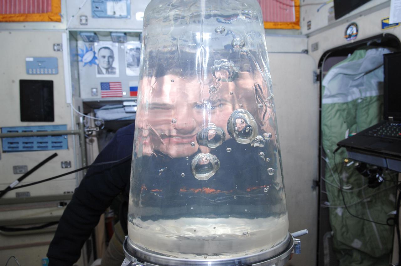
ISS034-E-010446 (31 Dec. 2012) --- Russian cosmonaut Roman Romanenko, Expedition 34 flight engineer, looks through a Rodnik tank in the Zvezda Service Module of the International Space Station. Romanenko performed a water transfer from a Rodnik tank in the Progress to a Rodnik tank in the Zvezda Service Module. Note the multiple refractions of the cosmonaut?s head and shoulders in the bubbles.
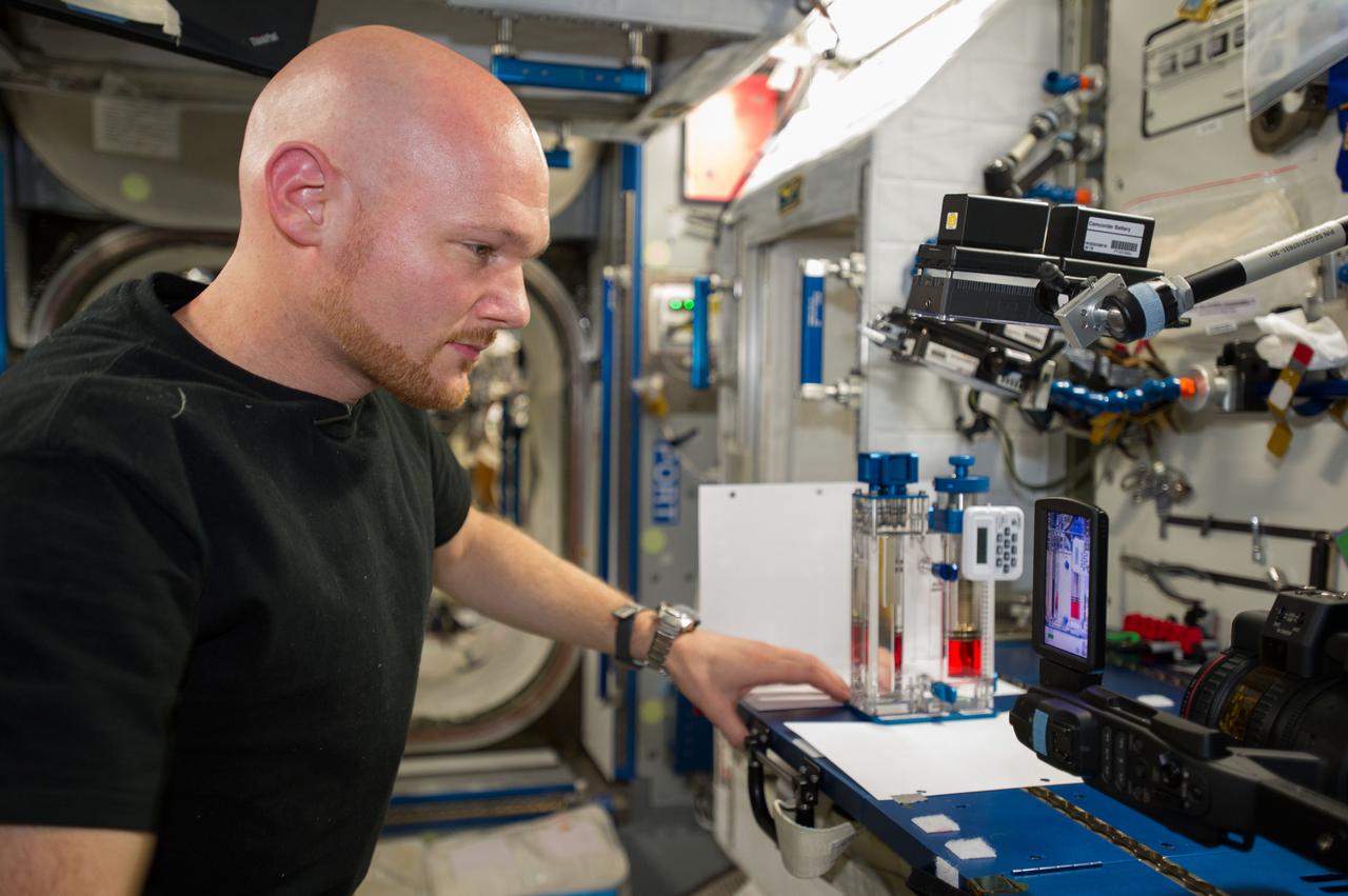
ISS040-E-015523 (19 June 2014) --- European Space Agency astronaut Alexander Gerst, Expedition 40 flight engineer, conducts a session with the Capillary Flow Experiment (CFE-2) in the Harmony node of the International Space Station. CFE is a suite of fluid physics experiments that investigate how fluids behave in microgravity which could benefit water and fuel delivery systems on future spacecraft. Scientists designed the CFE-2 to study properties of fluids and bubbles inside containers with a specific 3-D geometry.
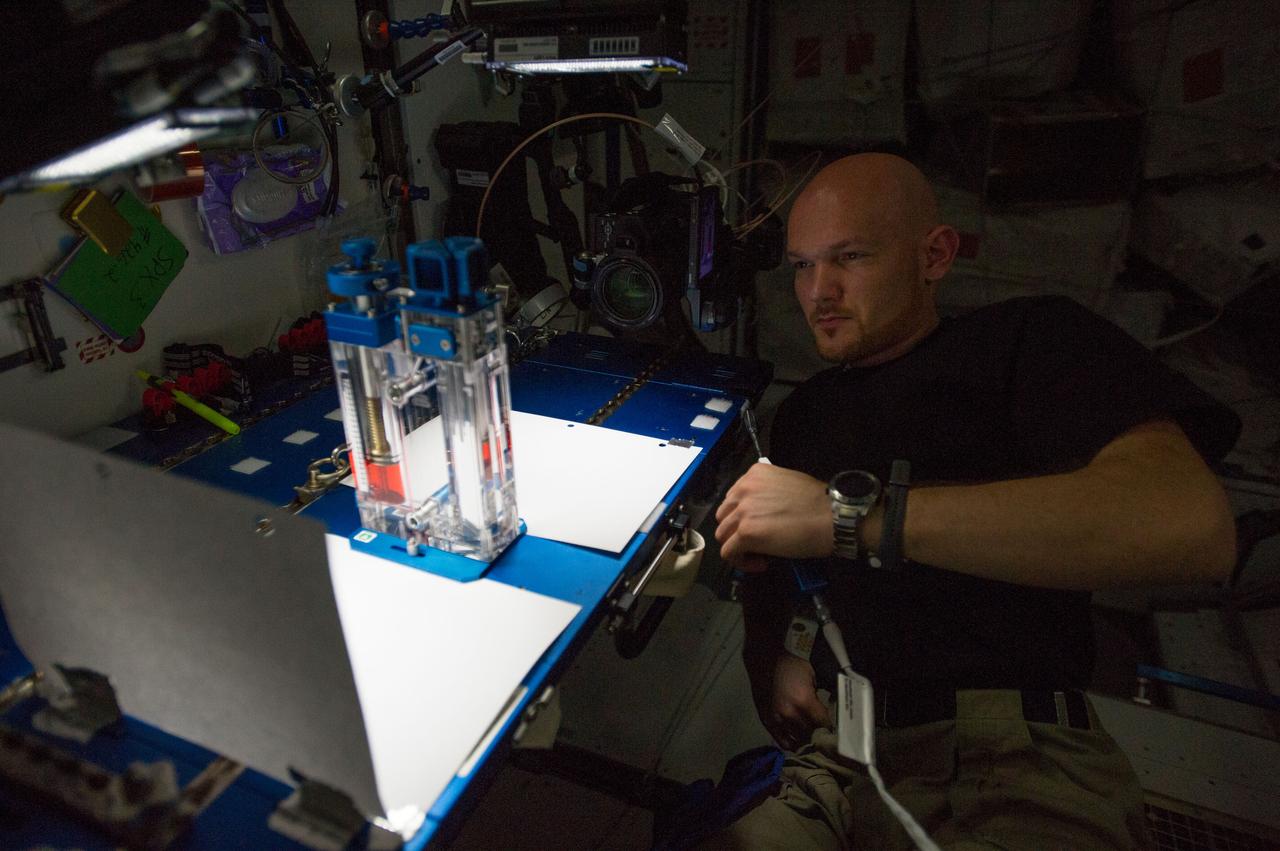
ISS040-E-015532 (19 June 2014) --- European Space Agency astronaut Alexander Gerst, Expedition 40 flight engineer, conducts a session with the Capillary Flow Experiment (CFE-2) in the Harmony node of the International Space Station. CFE is a suite of fluid physics experiments that investigate how fluids behave in microgravity which could benefit water and fuel delivery systems on future spacecraft. Scientists designed the CFE-2 to study properties of fluids and bubbles inside containers with a specific 3-D geometry.
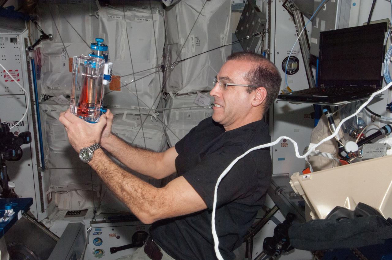
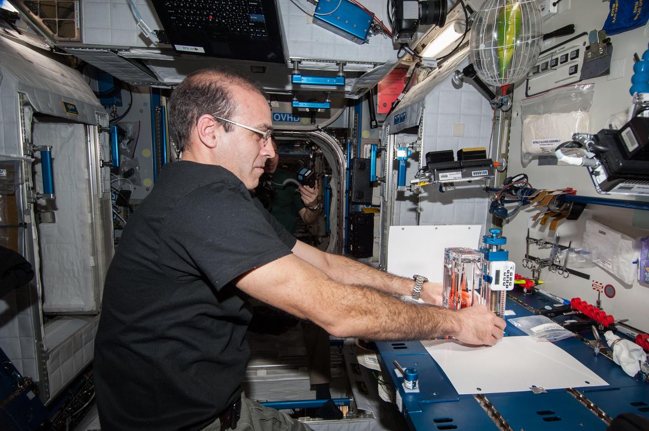
ISS038-E-025016 (3 Jan. 2014) --- NASA astronaut Rick Mastracchio, Expedition 38 flight engineer, conducts a session with the Capillary Flow Experiment (CFE-2) in the Harmony node of the International Space Station. CFE is a suite of fluid physics experiments that investigate how fluids behave in microgravity which could benefit water and fuel delivery systems on future spacecraft. Scientists designed the CFE-2 to study properties of fluids and bubbles inside containers with a specific 3-D geometry.
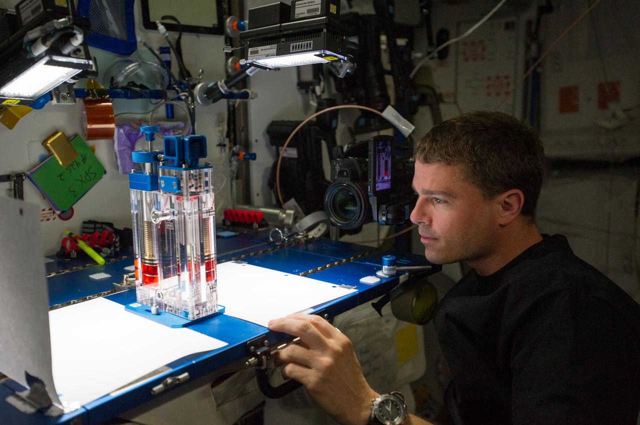
ISS040-E-015539 (19 June 2014) --- NASA astronaut Reid Wiseman, Expedition 40 flight engineer, conducts a session with the Capillary Flow Experiment (CFE-2) in the Harmony node of the International Space Station. CFE is a suite of fluid physics experiments that investigate how fluids behave in microgravity which could benefit water and fuel delivery systems on future spacecraft. Scientists designed the CFE-2 to study properties of fluids and bubbles inside containers with a specific 3-D geometry.
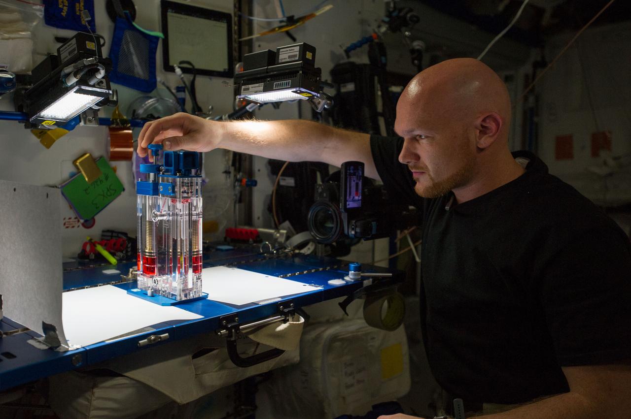
ISS040-E-015543 (19 June 2014) --- European Space Agency astronaut Alexander Gerst, Expedition 40 flight engineer, conducts a session with the Capillary Flow Experiment (CFE-2) in the Harmony node of the International Space Station. CFE is a suite of fluid physics experiments that investigate how fluids behave in microgravity which could benefit water and fuel delivery systems on future spacecraft. Scientists designed the CFE-2 to study properties of fluids and bubbles inside containers with a specific 3-D geometry.
ISS038-E-025000 (3 Jan. 2014) --- NASA astronaut Rick Mastracchio, Expedition 38 flight engineer, speaks in a microphone while conducting a session with the Capillary Flow Experiment (CFE-2) in the Harmony node of the International Space Station. CFE is a suite of fluid physics experiments that investigate how fluids behave in microgravity which could benefit water and fuel delivery systems on future spacecraft. Scientists designed the CFE-2 to study properties of fluids and bubbles inside containers with a specific 3-D geometry.
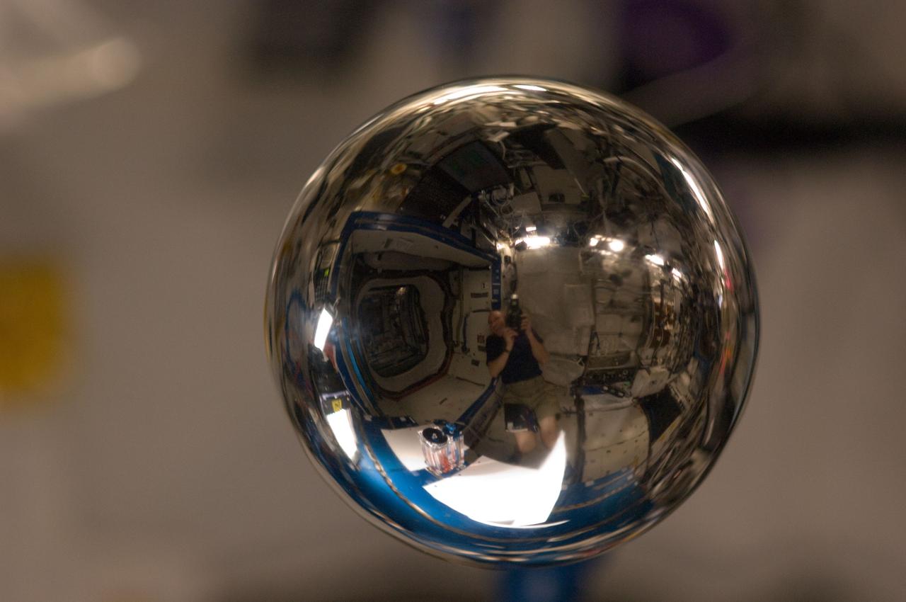
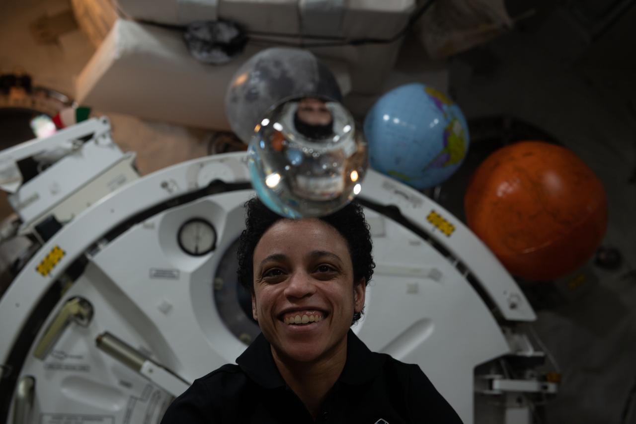
ISS030-E-108804 (28 Feb. 2012) -- A close look at this four-inch polished metal sphere onboard the International Space Station reveals a reflected image of NASA astronaut Don Pettit, Expedition 30 flight engineer. Using a 105-mm lens, Pettit took a series of pictures of the sphere. Also visible is hardware from the Capillary Flow Experiment-2 (CFE-2) Vane Gap 1 Experiment, in the U.S. Laboratory Destiny.
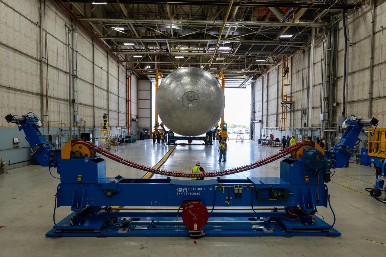
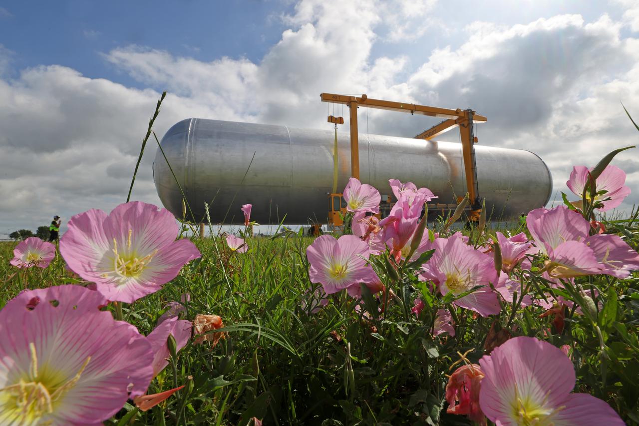
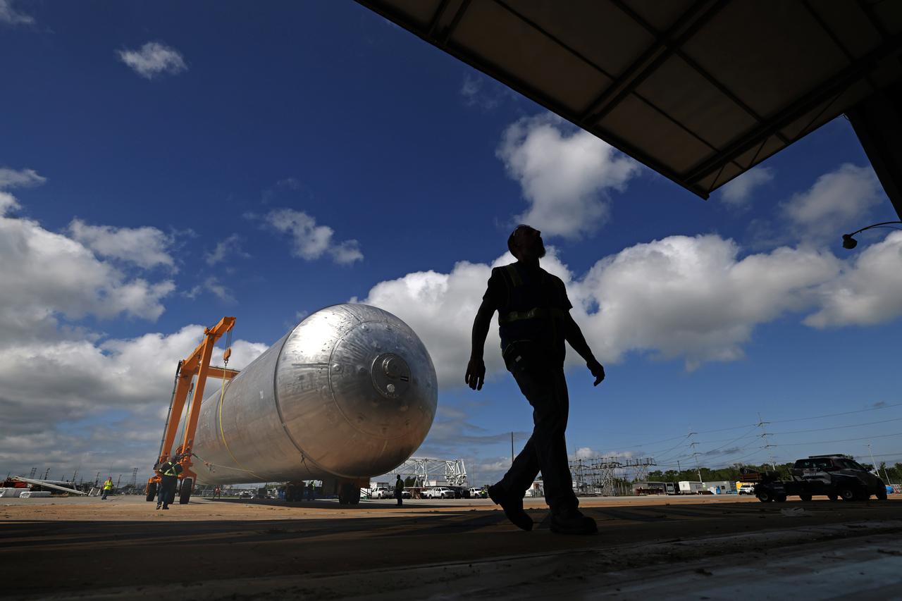
The core stage liquid hydrogen tank for the Artemis III mission completed proof testing, and technicians returned it to the main factory building at NASA’s Michoud Assembly Facility in New Orleans where it will undergo more outfitting. As part of proof testing, technicians apply a simple soap solution and check for leaks by observing any bubble formation on the welds. The technician removed the bubble solution with distilled water and then dried the area of application to prevent corrosion. To build the Space Launch System (SLS) rocket’s 130-foot core stage liquid hydrogen tank, engineers use robotic tools to weld five-barrel segments. This process results in a tank with around 1,900 feet, or more than six football fields, of welds that must be tested by hand. After the leak tests, the core stage lead, Boeing, pressurized the SLS tank to further ensure there were no leaks. After it passed proof testing, technicians moved the Artemis III liquid hydrogen tank to Michoud’s main factory. Soon, the technicians will prime and apply a foam-based thermal protection system that protects the tank during launch. Later, the tank will be joined with other parts of the core stage to form the entire 212-foot rocket stage with its four RS-25 engines that produce 2 million pounds of thrust to help launch the rocket. Artemis III will land the first astronauts on the lunar surface.
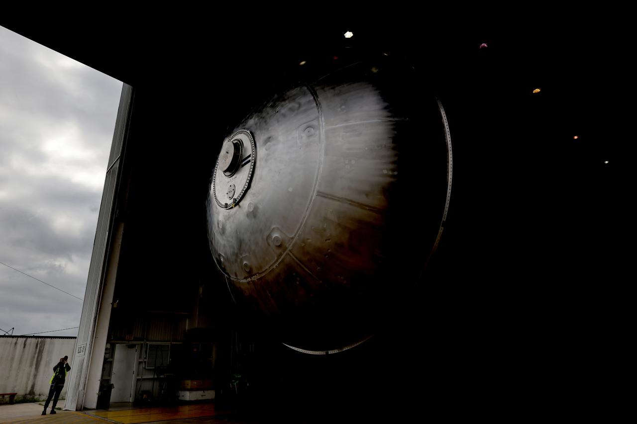
The core stage liquid hydrogen tank for the Artemis III mission completed proof testing, and technicians returned it to the main factory building at NASA’s Michoud Assembly Facility in New Orleans where it will undergo more outfitting. As part of proof testing, technicians apply a simple soap solution and check for leaks by observing any bubble formation on the welds. The technician removed the bubble solution with distilled water and then dried the area of application to prevent corrosion. To build the Space Launch System (SLS) rocket’s 130-foot core stage liquid hydrogen tank, engineers use robotic tools to weld five-barrel segments. This process results in a tank with around 1,900 feet, or more than six football fields, of welds that must be tested by hand. After the leak tests, the core stage lead, Boeing, pressurized the SLS tank to further ensure there were no leaks. After it passed proof testing, technicians moved the Artemis III liquid hydrogen tank to Michoud’s main factory. Soon, the technicians will prime and apply a foam-based thermal protection system that protects the tank during launch. Later, the tank will be joined with other parts of the core stage to form the entire 212-foot rocket stage with its four RS-25 engines that produce 2 million pounds of thrust to help launch the rocket. Artemis III will land the first astronauts on the lunar surface.
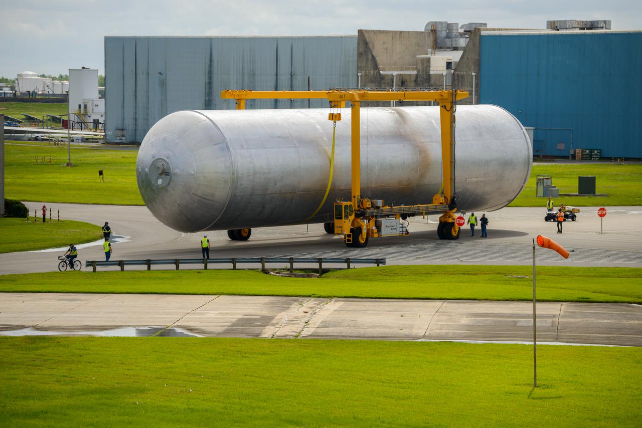
The core stage liquid hydrogen tank for the Artemis III mission completed proof testing, and technicians returned it to the main factory building at NASA’s Michoud Assembly Facility in New Orleans where it will undergo more outfitting. As part of proof testing, technicians apply a simple soap solution and check for leaks by observing any bubble formation on the welds. The technician removed the bubble solution with distilled water and then dried the area of application to prevent corrosion. To build the Space Launch System (SLS) rocket’s 130-foot core stage liquid hydrogen tank, engineers use robotic tools to weld five-barrel segments. This process results in a tank with around 1,900 feet, or more than six football fields, of welds that must be tested by hand. After the leak tests, the core stage lead, Boeing, pressurized the SLS tank to further ensure there were no leaks. After it passed proof testing, technicians moved the Artemis III liquid hydrogen tank to Michoud’s main factory. Soon, the technicians will prime and apply a foam-based thermal protection system that protects the tank during launch. Later, the tank will be joined with other parts of the core stage to form the entire 212-foot rocket stage with its four RS-25 engines that produce 2 million pounds of thrust to help launch the rocket. Artemis III will land the first astronauts on the lunar surface.
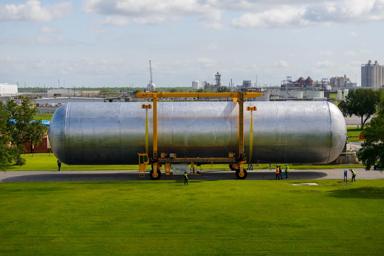
The core stage liquid hydrogen tank for the Artemis III mission completed proof testing, and technicians returned it to the main factory building at NASA’s Michoud Assembly Facility in New Orleans where it will undergo more outfitting. As part of proof testing, technicians apply a simple soap solution and check for leaks by observing any bubble formation on the welds. The technician removed the bubble solution with distilled water and then dried the area of application to prevent corrosion. To build the Space Launch System (SLS) rocket’s 130-foot core stage liquid hydrogen tank, engineers use robotic tools to weld five-barrel segments. This process results in a tank with around 1,900 feet, or more than six football fields, of welds that must be tested by hand. After the leak tests, the core stage lead, Boeing, pressurized the SLS tank to further ensure there were no leaks. After it passed proof testing, technicians moved the Artemis III liquid hydrogen tank to Michoud’s main factory. Soon, the technicians will prime and apply a foam-based thermal protection system that protects the tank during launch. Later, the tank will be joined with other parts of the core stage to form the entire 212-foot rocket stage with its four RS-25 engines that produce 2 million pounds of thrust to help launch the rocket. Artemis III will land the first astronauts on the lunar surface.

jsc2024e043916 (3/29/2024) ---The Packed Bed Reactor Experiment – Water Recovery (PBRE-WR) completed a series of tests in the Microgravity Science Glovebox on the International Space Station. Image of PBRE-WR during low flow conditions. Bubbles and voids (darker spots) are captured using a high-speed video camera at 10 fps. They are measured to determine gas holdup during various test conditions. In this image, the liquid flow was 20 kg/hr and the gas flow was 100 gr/hr. Scientists aim to learn more about how reduced gravity affects the performance and reliability of various filtration systems.
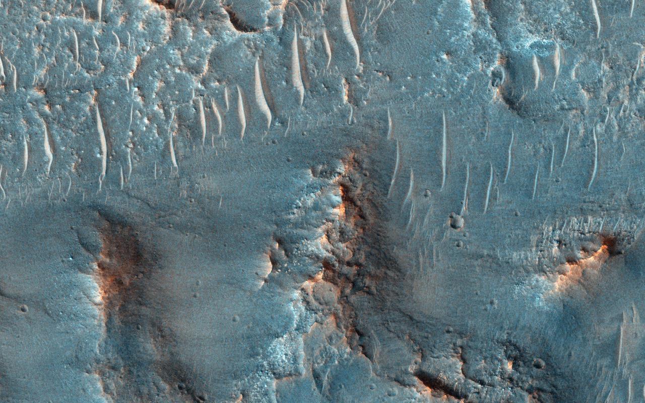
On Earth, cataracts represent regions where a river's gradient increases enough to create so much turbulence, that air gets incorporated into the water body forming a bubbly current sometimes called "whitewater". This image covers a location that may have acted as a cataract in the Kasei valley region. This observation from NASA Mars Reconnaissance Orbiter shows samples of bedrock lithologies which give us a measure of the post-flood erosion and modification history for the floor of Kasei Valles While there is a HiRISE stereo pair adjacent to this location that captures much of this cataract, it also misses some of the head scarp that might be the most useful, scientifically. http://photojournal.jpl.nasa.gov/catalog/PIA19351
ISS038-E-025002 (3 Jan. 2014) --- NASA astronaut Rick Mastracchio, Expedition 38 flight engineer, conducts a session with the Capillary Flow Experiment (CFE-2) in the Harmony node of the International Space Station. CFE is a suite of fluid physics experiments that investigate how fluids behave in microgravity which could benefit water and fuel delivery systems on future spacecraft. Scientists designed the CFE-2 to study properties of fluids and bubbles inside containers with a specific 3-D geometry. NASA astronaut Mike Hopkins (mostly obscured in the background), flight engineer, uses a still camera to photograph the session.
S69-34313 (20 May 1969) --- Astronaut Eugene A. Cernan is shown spinning a water bag to demonstrate the collection of hydrogen bubbles in this color reproduction taken from the fifth telecast made by the color television camera aboard the Apollo 10 spacecraft. When this picture was made the Apollo 10 spacecraft was approximately 175,300 nautical miles from Earth, and only 43,650 nautical miles from the moon. Cernan is the Apollo 10 lunar module pilot. Also, aboard Apollo 10 were astronauts Thomas P. Stafford, commander; and John W. Young, command module pilot.
ISS038-E-025002 (3 Jan. 2014) --- NASA astronaut Rick Mastracchio, Expedition 38 flight engineer, conducts a session with the Capillary Flow Experiment (CFE-2) in the Harmony node of the International Space Station. CFE is a suite of fluid physics experiments that investigate how fluids behave in microgravity which could benefit water and fuel delivery systems on future spacecraft. Scientists designed the CFE-2 to study properties of fluids and bubbles inside containers with a specific 3-D geometry. NASA astronaut Mike Hopkins (mostly obscured in the background), flight engineer, uses a still camera to photograph the session.
jsc2022e072960 (9/16/2022) --- Front view of flow of mixture of hydrophobic medium sand particles, water, and air. After mixing hydrophobic medium sand particles with water and air, researchers flow the mixture through the pipe. Both agglomerates and excess free sand particles are visible. Researchers also observe the segregation phenomenon during the flow of this particular mixture. Agglomerates do not occupy the pipe uniformly and do not always flow at the same speed. Catastrophic Post-Wildfire Mudflows studies the formation and stability of this bubble-sand structure in microgravity. A better understanding of these phenomena could improve the understanding, modeling, and predicting of mudflows and support development of innovative solutions to prevent catastrophic post-fire events. Image courtesy of the UCSD Geo-Micromechanics Research Group.
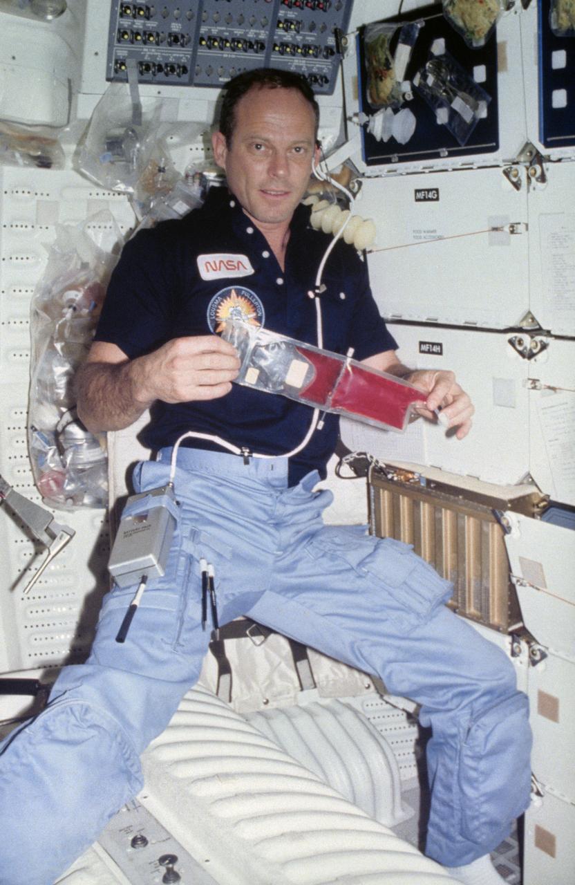
S82-28914 (26 March 1982) --- Astronaut Jack R. Lousma, STS-3 commander, spins a package of colored liquid in zero-gravity aboard the Earth-orbiting space shuttle Columbia. He was actually creating a centrifuge to conduct a test involving the separation of bubbles from the liquid rehydrated strawberry powder for visible clarity. The gas from liquid experiment is a test devised by scientist-astronaut William E. Thornton. The gun-like device at center of left edge is a water-dispenser which the astronauts use in rehydrating food packets, many of which can be seen in the background of this middeck area of the Columbia. Astronaut C. Gordon Fullerton, pilot, exposed this frame with a 35mm camera. Photo credit: NASA
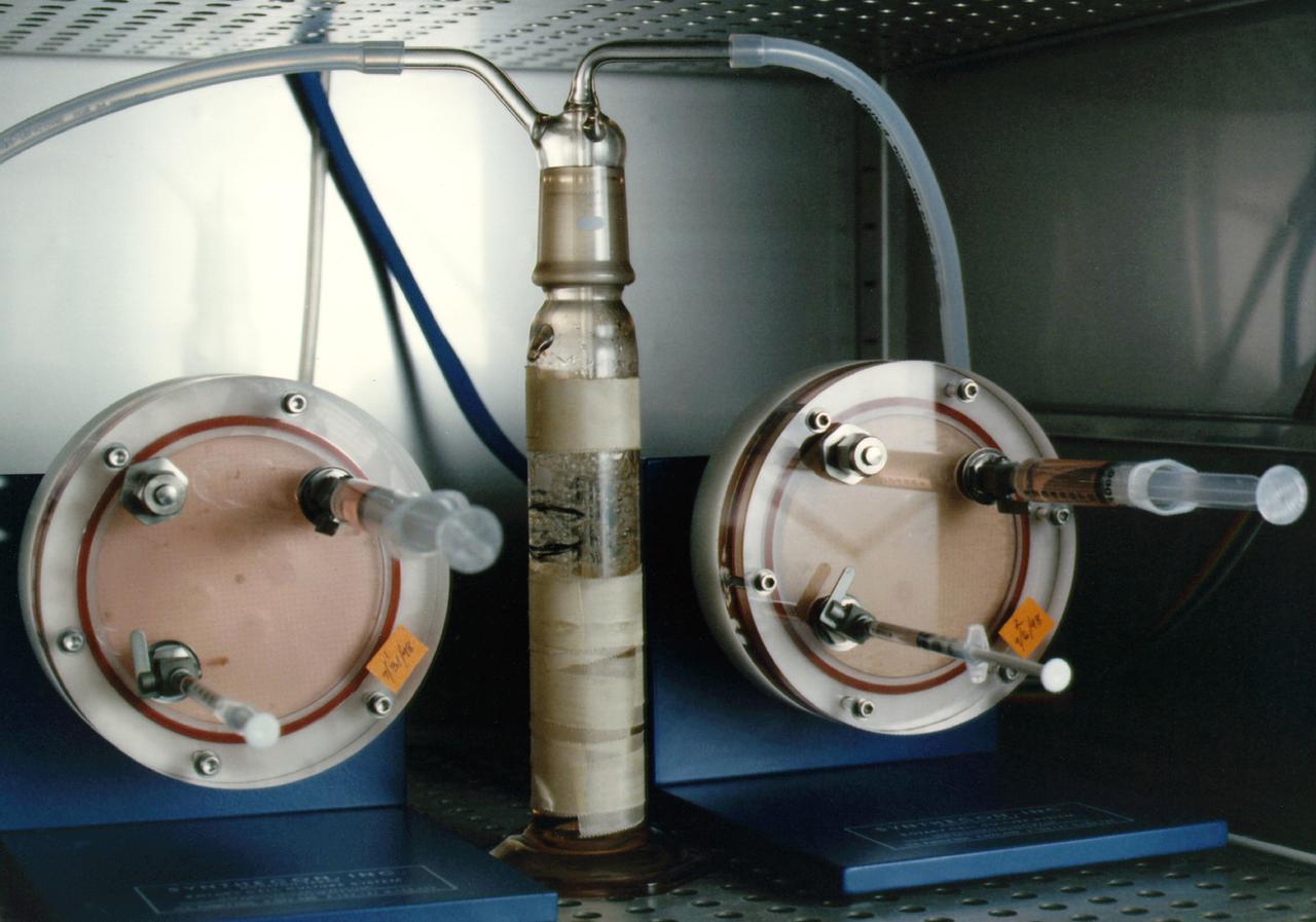
NASA's Marshall Space Flight Center (MSFC) is sponsoring research with Bioreactors, rotating wall vessels designed to grow tissue samples in space, to understand how breast cancer works. This ground-based work studies the growth and assembly of human mammary epithelial cells (HMEC) from breast cancer susceptible tissue. Radiation can make the cells cancerous, thus allowing better comparisons of healthy vs. tunourous tissues. Here, two High-Aspect Ratio Vessels turn at about 12 rmp to keep breast tissue constructs suspended inside the culture media. Syringes allow scientists to pull for analysis during growth sequences. The tube in the center is a water bubbler that dehumidifies the air to prevent evaporation of the media and thus the appearance of destructive bubbles in the bioreactor.
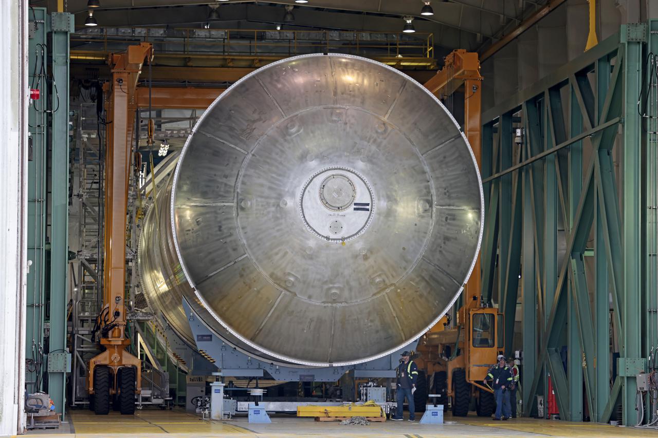
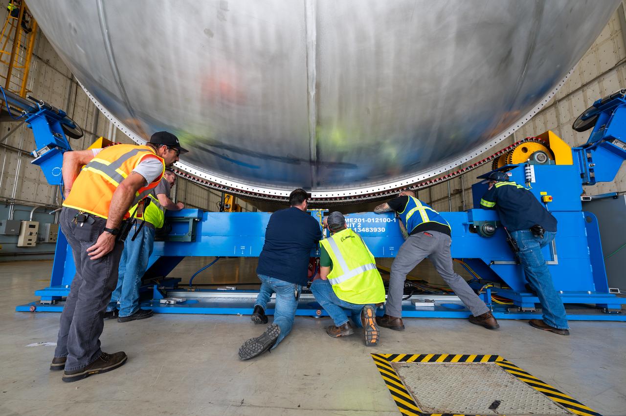
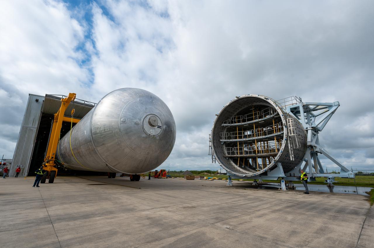
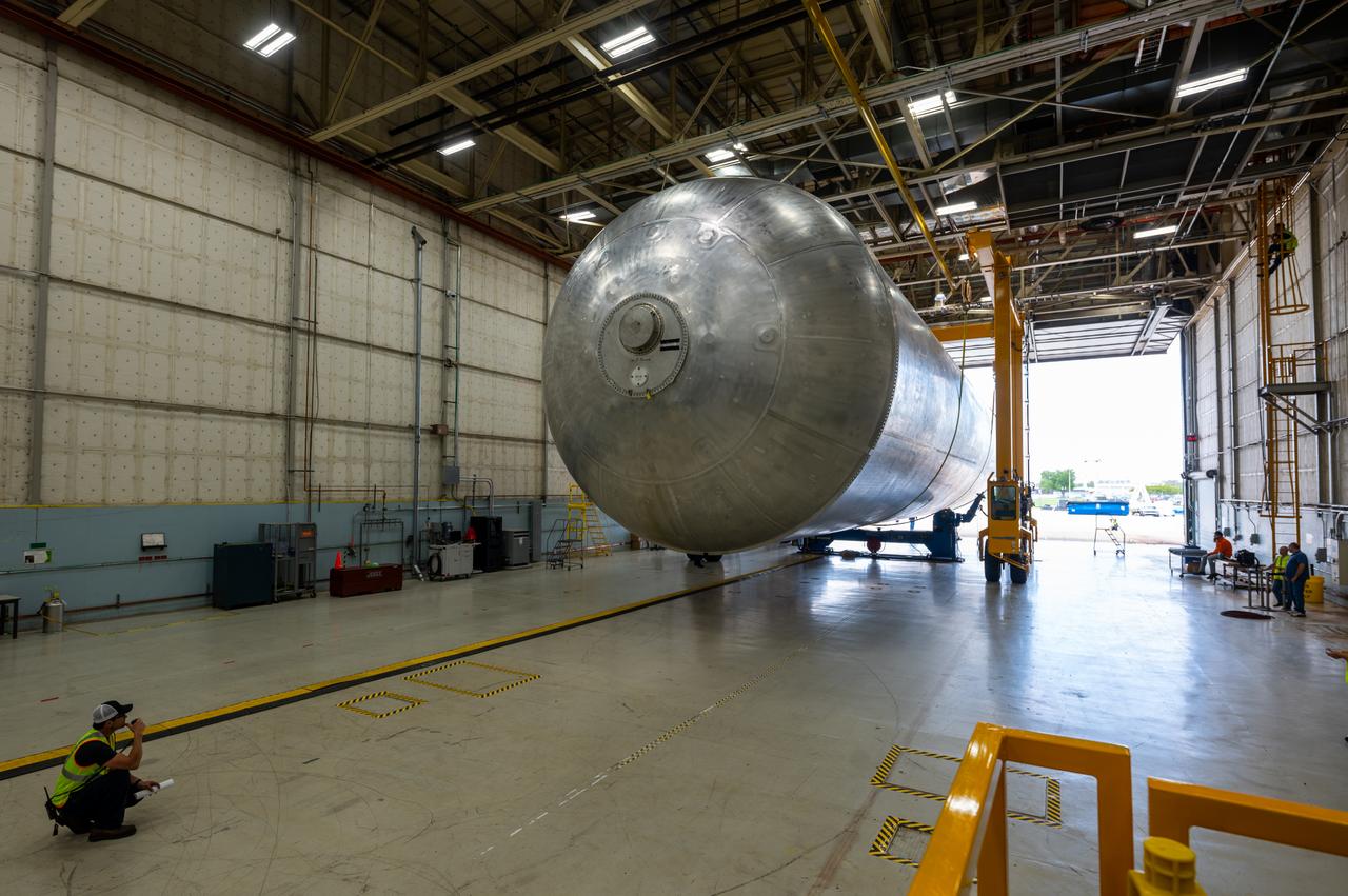
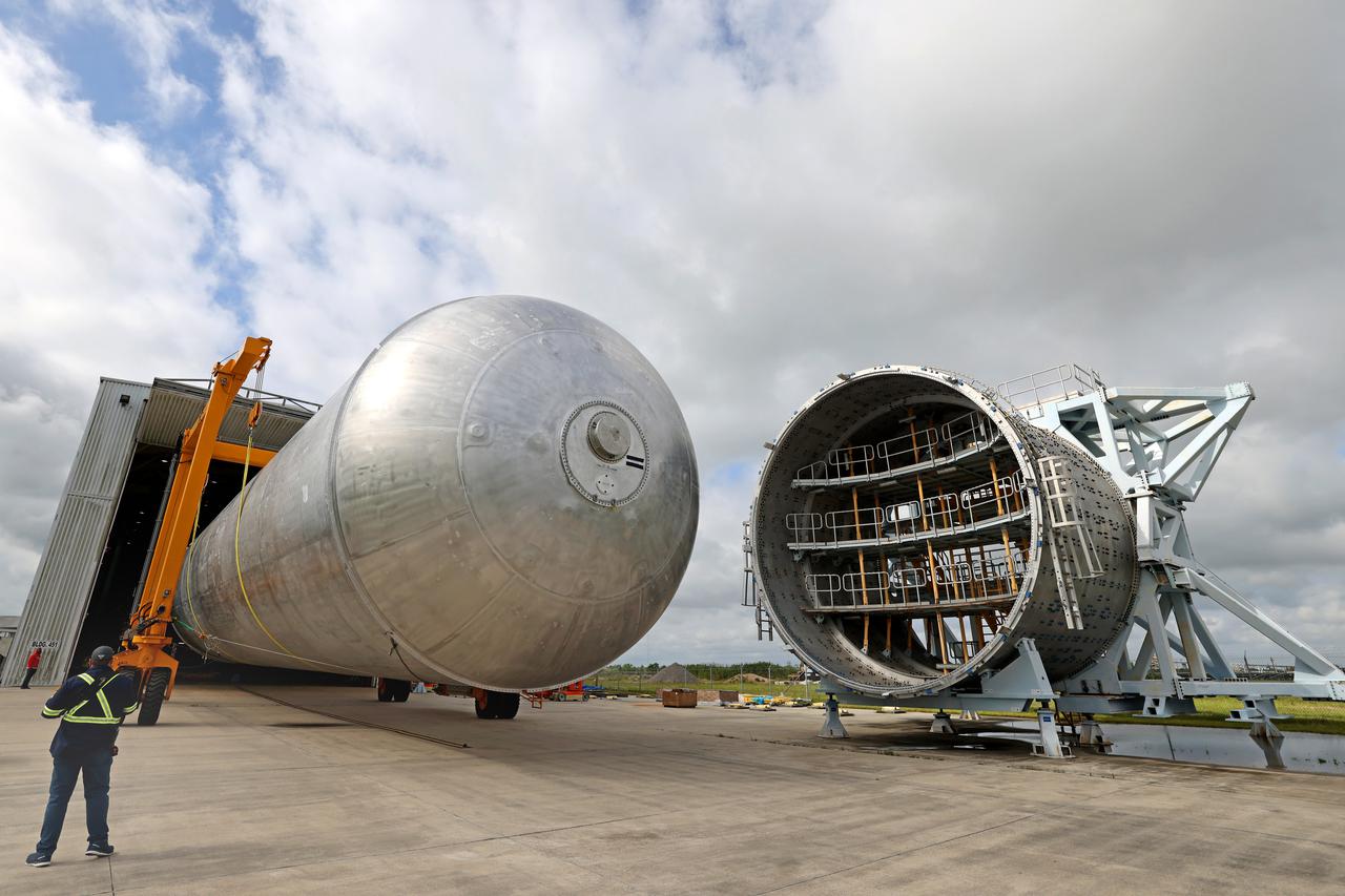
The core stage liquid hydrogen tank for the Artemis III mission completed proof testing, and technicians returned it to the main factory building at NASA’s Michoud Assembly Facility in New Orleans where it will undergo more outfitting. As part of proof testing, technicians apply a simple soap solution and check for leaks by observing any bubble formation on the welds. The technician removed the bubble solution with distilled water and then dried the area of application to prevent corrosion. To build the Space Launch System (SLS) rocket’s 130-foot core stage liquid hydrogen tank, engineers use robotic tools to weld five-barrel segments. This process results in a tank with around 1,900 feet, or more than six football fields, of welds that must be tested by hand. After the leak tests, the core stage lead, Boeing, pressurized the SLS tank to further ensure there were no leaks. After it passed proof testing, technicians moved the Artemis III liquid hydrogen tank to Michoud’s main factory. Soon, the technicians will prime and apply a foam-based thermal protection system that protects the tank during launch. Later, the tank will be joined with other parts of the core stage to form the entire 212-foot rocket stage with its four RS-25 engines that produce 2 million pounds of thrust to help launch the rocket. Artemis III will land the first astronauts on the lunar surface. Photographed on Monday, April 18, 2022. Image credit: NASA/Michael DeMocker
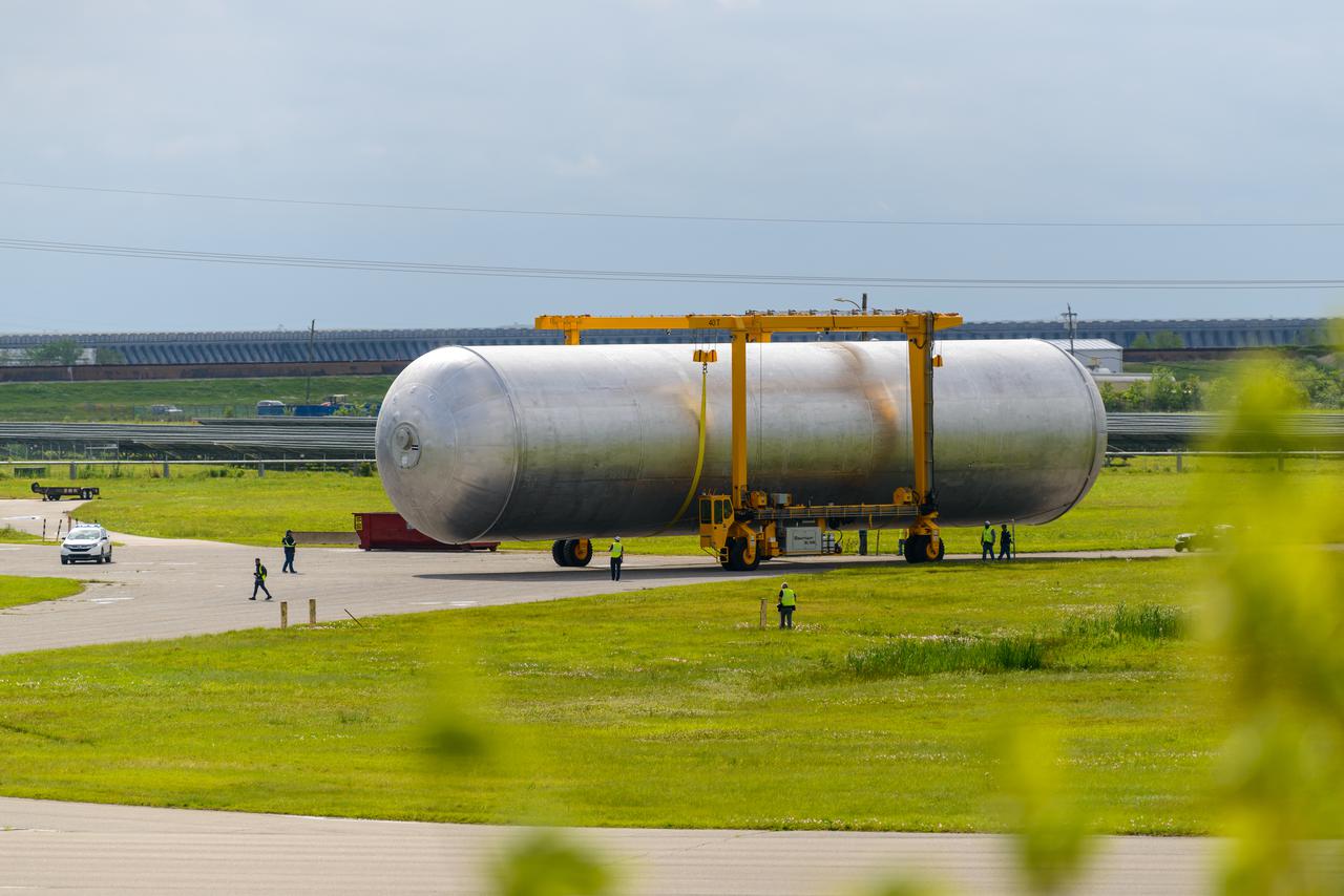
The core stage liquid hydrogen tank for the Artemis III mission completed proof testing, and technicians returned it to the main factory building at NASA’s Michoud Assembly Facility in New Orleans where it will undergo more outfitting. As part of proof testing, technicians apply a simple soap solution and check for leaks by observing any bubble formation on the welds. The technician removed the bubble solution with distilled water and then dried the area of application to prevent corrosion. To build the Space Launch System (SLS) rocket’s 130-foot core stage liquid hydrogen tank, engineers use robotic tools to weld five-barrel segments. This process results in a tank with around 1,900 feet, or more than six football fields, of welds that must be tested by hand. After the leak tests, the core stage lead, Boeing, pressurized the SLS tank to further ensure there were no leaks. After it passed proof testing, technicians moved the Artemis III liquid hydrogen tank to Michoud’s main factory. Soon, the technicians will prime and apply a foam-based thermal protection system that protects the tank during launch. Later, the tank will be joined with other parts of the core stage to form the entire 212-foot rocket stage with its four RS-25 engines that produce 2 million pounds of thrust to help launch the rocket. Artemis III will land the first astronauts on the lunar surface. Photographed on Monday, April 18, 2022.
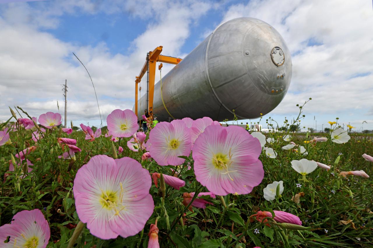
The core stage liquid hydrogen tank for the Artemis III mission completed proof testing, and technicians returned it to the main factory building at NASA’s Michoud Assembly Facility in New Orleans where it will undergo more outfitting. As part of proof testing, technicians apply a simple soap solution and check for leaks by observing any bubble formation on the welds. The technician removed the bubble solution with distilled water and then dried the area of application to prevent corrosion. To build the Space Launch System (SLS) rocket’s 130-foot core stage liquid hydrogen tank, engineers use robotic tools to weld five-barrel segments. This process results in a tank with around 1,900 feet, or more than six football fields, of welds that must be tested by hand. After the leak tests, the core stage lead, Boeing, pressurized the SLS tank to further ensure there were no leaks. After it passed proof testing, technicians moved the Artemis III liquid hydrogen tank to Michoud’s main factory. Soon, the technicians will prime and apply a foam-based thermal protection system that protects the tank during launch. Later, the tank will be joined with other parts of the core stage to form the entire 212-foot rocket stage with its four RS-25 engines that produce 2 million pounds of thrust to help launch the rocket. Artemis III will land the first astronauts on the lunar surface. Photographed on Monday, April 18, 2022. Image credit: NASA/Michael DeMocker
The core stage liquid hydrogen tank for the Artemis III mission completed proof testing, and technicians returned it to the main factory building at NASA’s Michoud Assembly Facility in New Orleans where it will undergo more outfitting. As part of proof testing, technicians apply a simple soap solution and check for leaks by observing any bubble formation on the welds. The technician removed the bubble solution with distilled water and then dried the area of application to prevent corrosion. To build the Space Launch System (SLS) rocket’s 130-foot core stage liquid hydrogen tank, engineers use robotic tools to weld five-barrel segments. This process results in a tank with around 1,900 feet, or more than six football fields, of welds that must be tested by hand. After the leak tests, the core stage lead, Boeing, pressurized the SLS tank to further ensure there were no leaks. After it passed proof testing, technicians moved the Artemis III liquid hydrogen tank to Michoud’s main factory. Soon, the technicians will prime and apply a foam-based thermal protection system that protects the tank during launch. Later, the tank will be joined with other parts of the core stage to form the entire 212-foot rocket stage with its four RS-25 engines that produce 2 million pounds of thrust to help launch the rocket. Artemis III will land the first astronauts on the lunar surface. Photographed on Monday, April 18, 2022. Image credit: NASA/Michael DeMocker
The core stage liquid hydrogen tank for the Artemis III mission completed proof testing, and technicians returned it to the main factory building at NASA’s Michoud Assembly Facility in New Orleans where it will undergo more outfitting. As part of proof testing, technicians apply a simple soap solution and check for leaks by observing any bubble formation on the welds. The technician removed the bubble solution with distilled water and then dried the area of application to prevent corrosion. To build the Space Launch System (SLS) rocket’s 130-foot core stage liquid hydrogen tank, engineers use robotic tools to weld five-barrel segments. This process results in a tank with around 1,900 feet, or more than six football fields, of welds that must be tested by hand. After the leak tests, the core stage lead, Boeing, pressurized the SLS tank to further ensure there were no leaks. After it passed proof testing, technicians moved the Artemis III liquid hydrogen tank to Michoud’s main factory. Soon, the technicians will prime and apply a foam-based thermal protection system that protects the tank during launch. Later, the tank will be joined with other parts of the core stage to form the entire 212-foot rocket stage with its four RS-25 engines that produce 2 million pounds of thrust to help launch the rocket. Artemis III will land the first astronauts on the lunar surface. Photographed on Monday, April 18, 2022. Image credit: NASA/Michael DeMocker
The core stage liquid hydrogen tank for the Artemis III mission completed proof testing, and technicians returned it to the main factory building at NASA’s Michoud Assembly Facility in New Orleans where it will undergo more outfitting. As part of proof testing, technicians apply a simple soap solution and check for leaks by observing any bubble formation on the welds. The technician removed the bubble solution with distilled water and then dried the area of application to prevent corrosion. To build the Space Launch System (SLS) rocket’s 130-foot core stage liquid hydrogen tank, engineers use robotic tools to weld five-barrel segments. This process results in a tank with around 1,900 feet, or more than six football fields, of welds that must be tested by hand. After the leak tests, the core stage lead, Boeing, pressurized the SLS tank to further ensure there were no leaks. After it passed proof testing, technicians moved the Artemis III liquid hydrogen tank to Michoud’s main factory. Soon, the technicians will prime and apply a foam-based thermal protection system that protects the tank during launch. Later, the tank will be joined with other parts of the core stage to form the entire 212-foot rocket stage with its four RS-25 engines that produce 2 million pounds of thrust to help launch the rocket. Artemis III will land the first astronauts on the lunar surface. Photographed on Monday, April 18, 2022.
The core stage liquid hydrogen tank for the Artemis III mission completed proof testing, and technicians returned it to the main factory building at NASA’s Michoud Assembly Facility in New Orleans where it will undergo more outfitting. As part of proof testing, technicians apply a simple soap solution and check for leaks by observing any bubble formation on the welds. The technician removed the bubble solution with distilled water and then dried the area of application to prevent corrosion. To build the Space Launch System (SLS) rocket’s 130-foot core stage liquid hydrogen tank, engineers use robotic tools to weld five-barrel segments. This process results in a tank with around 1,900 feet, or more than six football fields, of welds that must be tested by hand. After the leak tests, the core stage lead, Boeing, pressurized the SLS tank to further ensure there were no leaks. After it passed proof testing, technicians moved the Artemis III liquid hydrogen tank to Michoud’s main factory. Soon, the technicians will prime and apply a foam-based thermal protection system that protects the tank during launch. Later, the tank will be joined with other parts of the core stage to form the entire 212-foot rocket stage with its four RS-25 engines that produce 2 million pounds of thrust to help launch the rocket. Artemis III will land the first astronauts on the lunar surface. Photographed on Monday, April 18, 2022.

The core stage liquid hydrogen tank for the Artemis III mission completed proof testing, and technicians returned it to the main factory building at NASA’s Michoud Assembly Facility in New Orleans where it will undergo more outfitting. As part of proof testing, technicians apply a simple soap solution and check for leaks by observing any bubble formation on the welds. The technician removed the bubble solution with distilled water and then dried the area of application to prevent corrosion. To build the Space Launch System (SLS) rocket’s 130-foot core stage liquid hydrogen tank, engineers use robotic tools to weld five-barrel segments. This process results in a tank with around 1,900 feet, or more than six football fields, of welds that must be tested by hand. After the leak tests, the core stage lead, Boeing, pressurized the SLS tank to further ensure there were no leaks. After it passed proof testing, technicians moved the Artemis III liquid hydrogen tank to Michoud’s main factory. Soon, the technicians will prime and apply a foam-based thermal protection system that protects the tank during launch. Later, the tank will be joined with other parts of the core stage to form the entire 212-foot rocket stage with its four RS-25 engines that produce 2 million pounds of thrust to help launch the rocket. Artemis III will land the first astronauts on the lunar surface. Photographed on Monday, April 18, 2022.
The core stage liquid hydrogen tank for the Artemis III mission completed proof testing, and technicians returned it to the main factory building at NASA’s Michoud Assembly Facility in New Orleans where it will undergo more outfitting. As part of proof testing, technicians apply a simple soap solution and check for leaks by observing any bubble formation on the welds. The technician removed the bubble solution with distilled water and then dried the area of application to prevent corrosion. To build the Space Launch System (SLS) rocket’s 130-foot core stage liquid hydrogen tank, engineers use robotic tools to weld five-barrel segments. This process results in a tank with around 1,900 feet, or more than six football fields, of welds that must be tested by hand. After the leak tests, the core stage lead, Boeing, pressurized the SLS tank to further ensure there were no leaks. After it passed proof testing, technicians moved the Artemis III liquid hydrogen tank to Michoud’s main factory. Soon, the technicians will prime and apply a foam-based thermal protection system that protects the tank during launch. Later, the tank will be joined with other parts of the core stage to form the entire 212-foot rocket stage with its four RS-25 engines that produce 2 million pounds of thrust to help launch the rocket. Artemis III will land the first astronauts on the lunar surface. Photographed on Monday, April 18, 2022. Image credit: NASA/Michael DeMocker
The core stage liquid hydrogen tank for the Artemis III mission completed proof testing, and technicians returned it to the main factory building at NASA’s Michoud Assembly Facility in New Orleans where it will undergo more outfitting. As part of proof testing, technicians apply a simple soap solution and check for leaks by observing any bubble formation on the welds. The technician removed the bubble solution with distilled water and then dried the area of application to prevent corrosion. To build the Space Launch System (SLS) rocket’s 130-foot core stage liquid hydrogen tank, engineers use robotic tools to weld five-barrel segments. This process results in a tank with around 1,900 feet, or more than six football fields, of welds that must be tested by hand. After the leak tests, the core stage lead, Boeing, pressurized the SLS tank to further ensure there were no leaks. After it passed proof testing, technicians moved the Artemis III liquid hydrogen tank to Michoud’s main factory. Soon, the technicians will prime and apply a foam-based thermal protection system that protects the tank during launch. Later, the tank will be joined with other parts of the core stage to form the entire 212-foot rocket stage with its four RS-25 engines that produce 2 million pounds of thrust to help launch the rocket. Artemis III will land the first astronauts on the lunar surface. Photographed on Monday, April 18, 2022. Image credit: NASA/Michael DeMocker
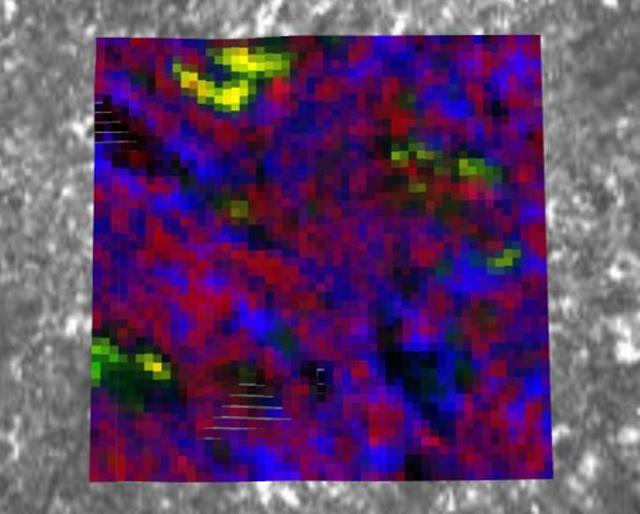
NASA's Perseverance Mars rover used its PIXL (Planetary Instrument for X-ray Lithochemistry) instrument to analyze the "Bellegarde" abrasion target – created when the rover scraped away surface area of the rock named "Rochette" – revealing salt minerals (the yellow color in the image). Salt crystals could have trapped bubbles of ancient water that, after the samples are returned to Earth, scientists could use to learn more about the environment these salts formed in. NASA's Jet Propulsion Laboratory built and manages operations of Perseverance and Ingenuity for the agency. Caltech in Pasadena, California, manages JPL for NASA. WATSON was built by Malin Space Science Systems (MSSS) in San Diego and is operated jointly by MSSS and JPL. A key objective for Perseverance's mission on Mars is astrobiology, including the search for signs of ancient microbial life. The rover will characterize the planet's geology and past climate, pave the way for human exploration of the Red Planet, and be the first mission to collect and cache Martian rock and regolith (broken rock and dust). Subsequent NASA missions, in cooperation with ESA (European Space Agency), would send spacecraft to Mars to collect these sealed samples from the surface and return them to Earth for in-depth analysis. The Mars 2020 Perseverance mission is part of NASA's Moon to Mars exploration approach, which includes Artemis missions to the Moon that will help prepare for human exploration of the Red Planet. https://photojournal.jpl.nasa.gov/catalog/PIA24835
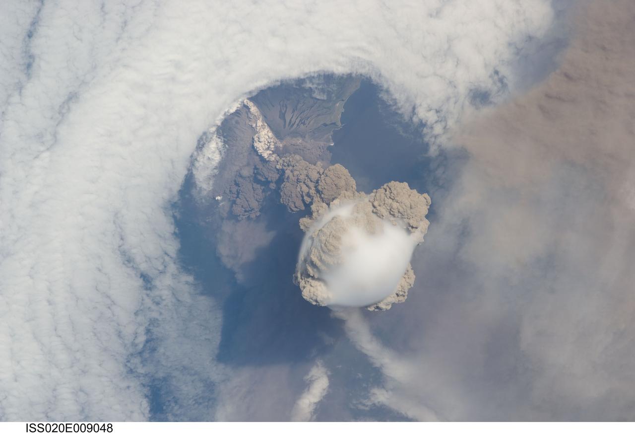
ISS020-E-009048 (12 June 2009) --- Sarychev Peak Volcano eruption, Kuril Islands, is featured in this image photographed by an Expedition 20 crew member on the International Space Station. A fortuitous orbit of the International Space Station allowed the astronauts this striking view of Sarychev volcano (Russia?s Kuril Islands, northeast of Japan) in an early stage of eruption on June 12, 2009. Sarychev Peak is one of the most active volcanoes in the Kuril Island chain and is located on the northwestern end of Matua Island. Prior to June 12, the last explosive eruption had occurred in 1989 with eruptions in 1986, 1976, 1954, and 1946 also producing lava flows. Ash from the June 2009 eruption has been detected 2407 kilometers ESE and 926 kilometers WNW of the volcano, and commercial airline flights are being diverted away from the region to minimize the danger of engine failures from ash intake. This detailed photograph is exciting to volcanologists because it captures several phenomena that occur during the earliest stages of an explosive volcanic eruption. The main column is one of a series of plumes that rose above Matua Island (48.1 degrees north latitude and 153.2 degrees east longitude) on June 12. The plume appears to be a combination of brown ash and white steam. The vigorously rising plume gives the steam a bubble-like appearance; the surrounding atmosphere has been shoved up by the shock wave of the eruption. The smooth white cloud on top may be water condensation that resulted from rapid rising and cooling of the air mass above the ash column, and is probably a transient feature (the eruption plume is starting to punch through). The structure also indicates that little to no shearing winds were present at the time to disrupt the plume. Another series of images, acquired 2-3 days after the start of eruptive activity, illustrate the effect of shearing winds on extent of the ash plumes across the Pacific Ocean. By contrast, a cloud of denser, gray ash ? most probably a pyroclastic flow -- appears to be hugging the ground, descending from the volcano summit. The rising eruption plume casts a shadow to the northwest of the island (bottom center). Brown ash at a lower altitude of the atmosphere spreads out above the ground at upper right. Low-level stratus clouds approach Matua Island from the east, wrapping around the lower slopes of the volcano. Only about 1.5 kilometers of the coastline of Matua Island (upper center) can be seen beneath the clouds and ash.