
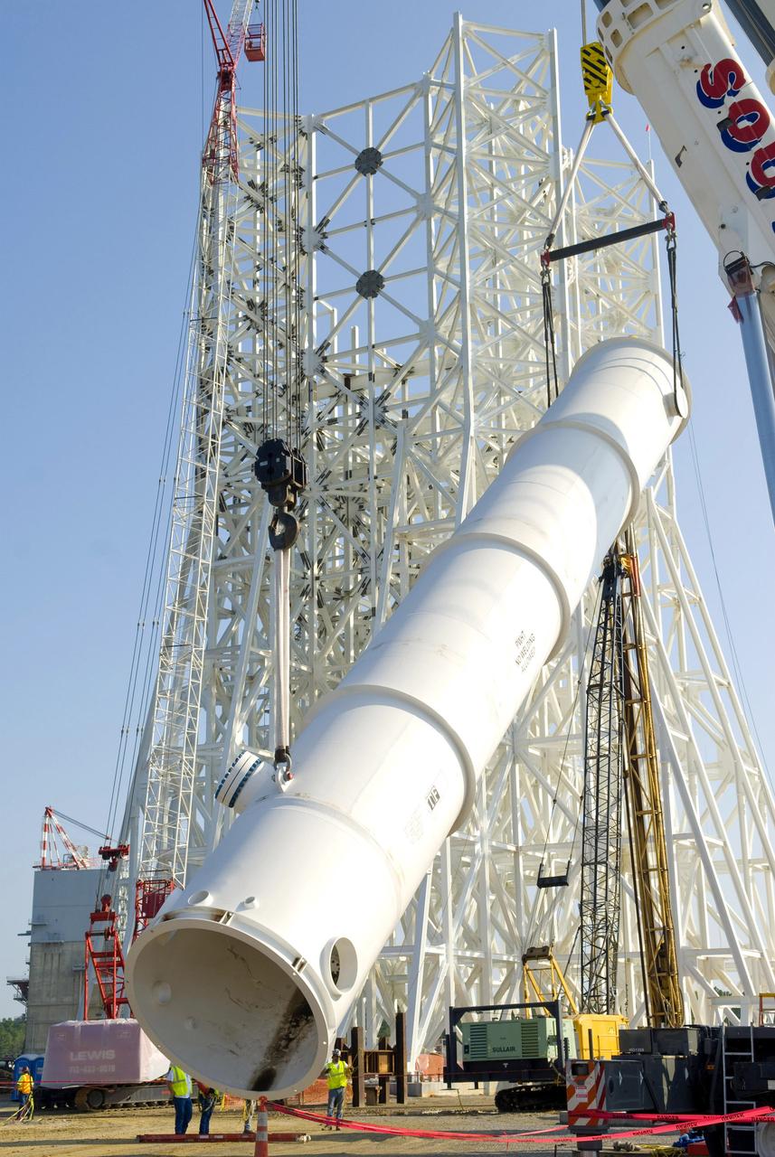
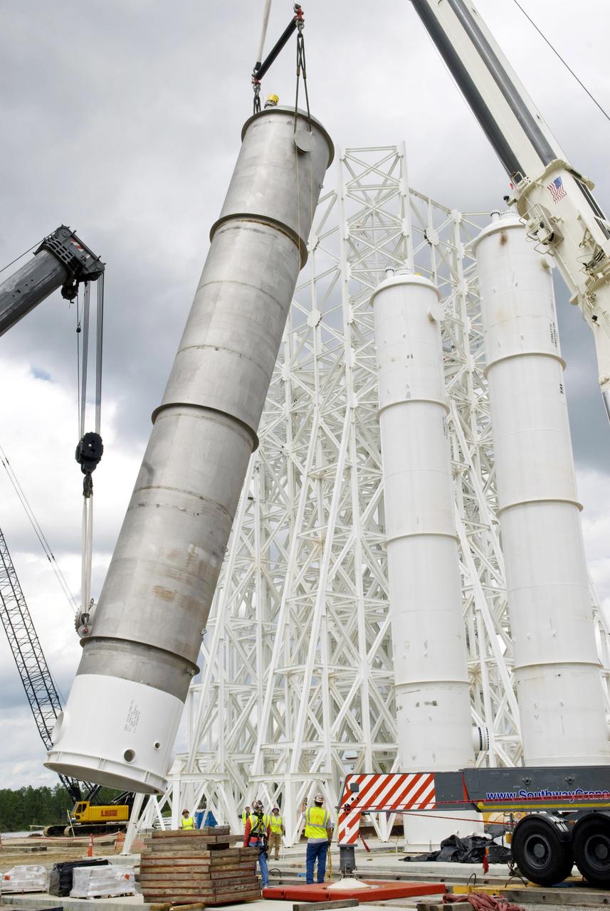
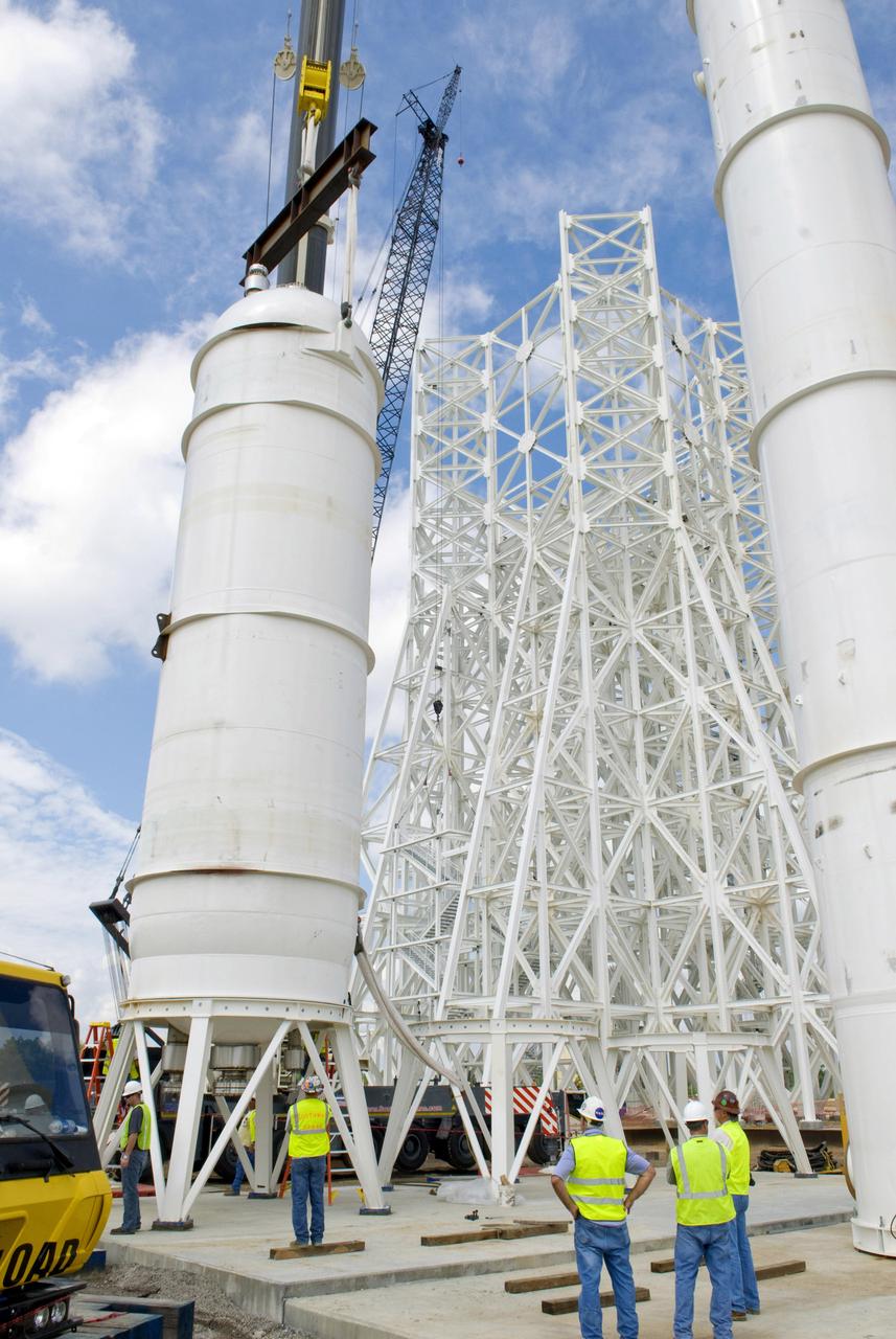
A water tank is lifted into place at the A-3 Test Stand being built at NASA's John C. Stennis Space Center. Fourteen water, liquid oxygen (LOX) and isopropyl alcohol (IPA) tanks are being installed to support the chemical steam generators to be used on the A-3 Test Stand. The IPA and LOX tanks will provide fuel for the generators. The water will allow the generators to produce steam that will be used to reduce pressure inside the stand's test cell diffuser, enabling operators to simulate altitudes up to 100,000 feet. In that way, operators can perform the tests needed on rocket engines being built to carry humans back to the moon and possibly beyond. The A-3 Test Stand is set for completion and activation in 2011.
A water tank is lifted into place at the A-3 Test Stand being built at NASA's John C. Stennis Space Center. Fourteen water, liquid oxygen (LOX) and isopropyl alcohol (IPA) tanks are being installed to support the chemical steam generators to be used on the A-3 Test Stand. The IPA and LOX tanks will provide fuel for the generators. The water will allow the generators to produce steam that will be used to reduce pressure inside the stand's test cell diffuser, enabling operators to simulate altitudes up to 100,000 feet. In that way, operators can perform the tests needed on rocket engines being built to carry humans back to the moon and possibly beyond. The A-3 Test Stand is set for completion and activation in 2011.
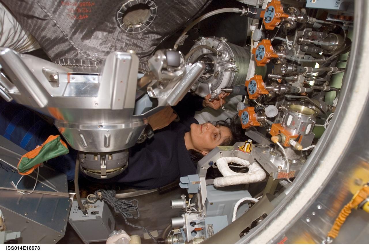
ISS014-E-18978 (5 April 2007) --- Astronaut Sunita L. Williams, Expedition 14 flight engineer, works with water tanks in the Progress 24 spacecraft docked to the International Space Station.
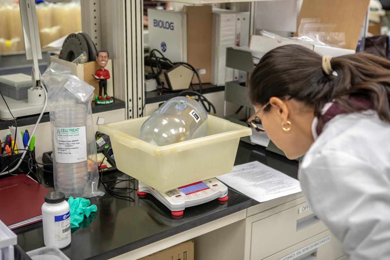
Kennedy Space Center’s Carolina Franco, Ph.D., weighs one of the water tanks, recently returned to the center after remaining on the International Space Station for the past five years, in the Florida spaceport’s Neil Armstrong Operations and Checkout Building on Nov. 13, 2019. Two tanks containing water were first sent to the orbiting laboratory in 2014 to study slosh, or the movement of water, in a zero-gravity environment to help engineers predict the movement of propellant in rocket tanks. Kennedy’s Air and Water Revitalization lab is studying the water tanks to determine if there is, or was, any microbial growth within them. The results will help NASA determine whether clean water can be stored in space for long-duration missions, an essential component to keeping astronauts safe and healthy as the agency prepares for missions to the Moon and beyond to Mars.
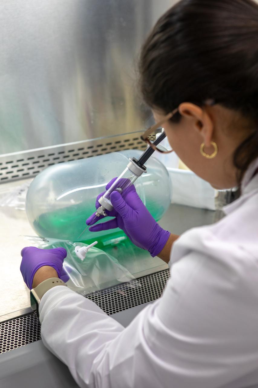
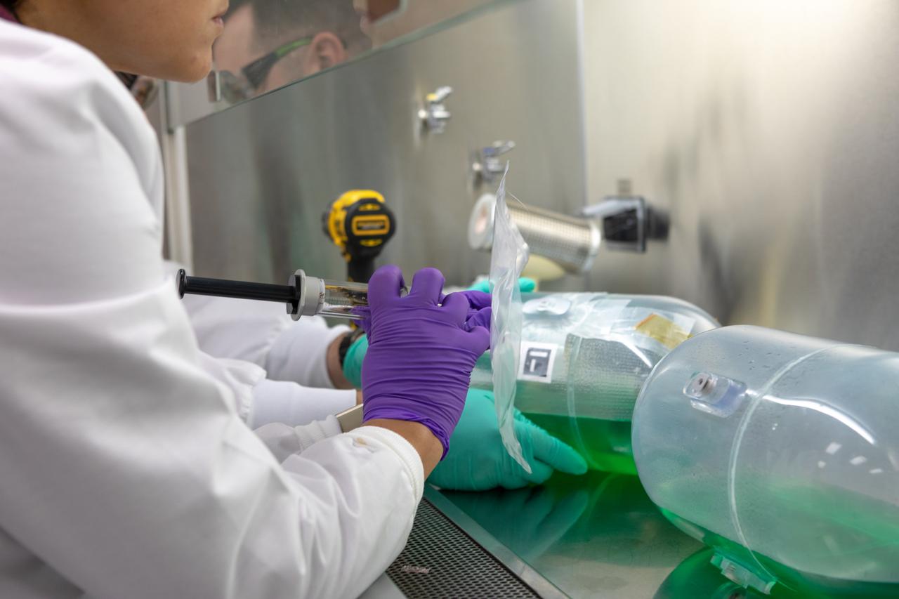
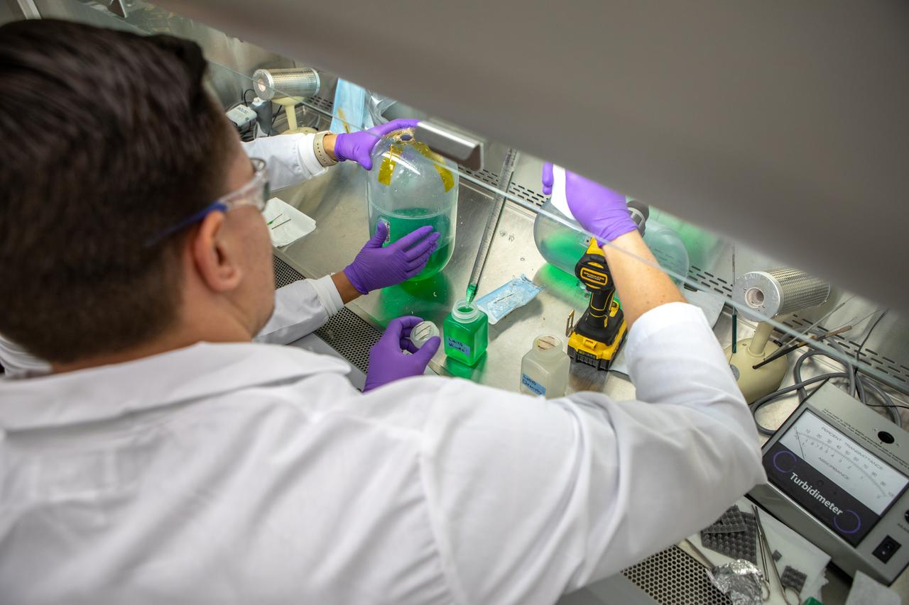
Kennedy Space Center’s Carolina Franco, Ph.D., collects samples from a water tank, filled with green dye, for a biological study in the Florida spaceport’s Neil Armstrong Operations and Checkout Building on Nov. 13, 2019. Two tanks have recently returned to Kennedy after spending the last five years on the International Space Station for an experiment to study slosh, or the movement of water, in a zero-gravity environment to help engineers predict the movement of propellant in rocket tanks. With the slosh experiment now concluded, Kennedy’s Air and Water Revitalization lab is studying the water tanks to determine if there is, or was, any microbial growth within them. The results will help NASA determine whether clean water can be stored in space for long-duration missions, an essential component to keeping astronauts safe and healthy as the agency prepares for missions to the Moon and beyond to Mars.
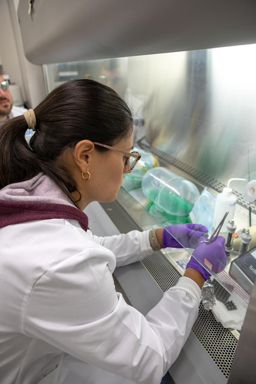
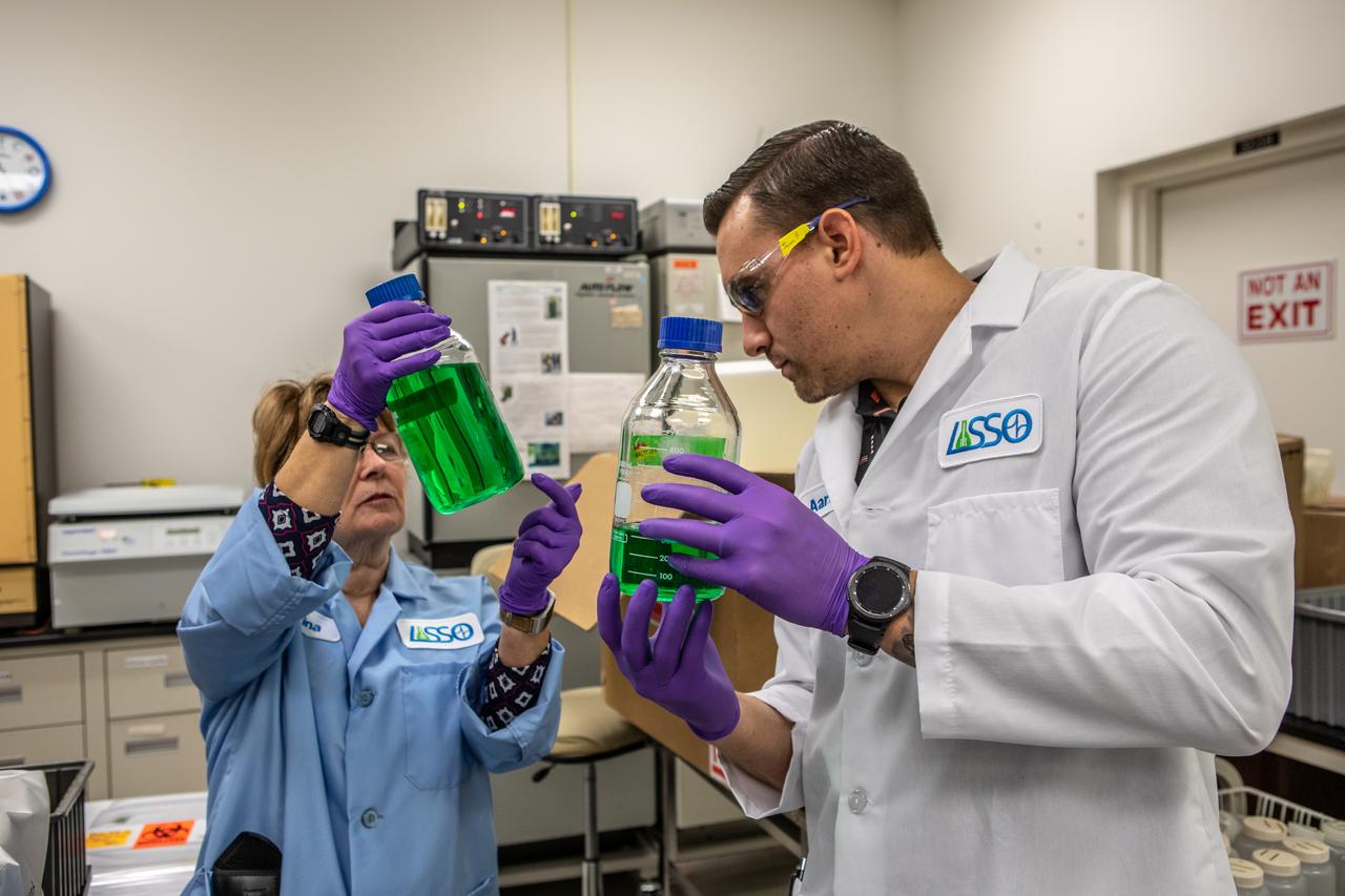
Kennedy Space Center’s Carolina Franco, Ph.D., conducts a biological study on two tanks of water, filled with green dye, in the Florida spaceport’s Neil Armstrong Operations and Checkout Building on Nov. 13, 2019. The tanks have recently returned to Kennedy after spending the last five years on the International Space Station for an experiment to study slosh, or the movement of water, in a zero-gravity environment to help engineers predict the movement of propellant in rocket tanks. Kennedy’s Air and Water Revitalization lab is studying the water tanks to determine if there is, or was, any microbial growth within them. The results will help NASA determine whether clean water can be stored in space for long-duration missions, an essential component to keeping astronauts safe and healthy as the agency prepares for missions to the Moon and beyond to Mars.

A Kennedy Space Center employee collects samples from a water tank, filled with green dye, for a biological study in the Florida spaceport’s Neil Armstrong Operations and Checkout Building on Nov. 13, 2019. Two tanks have recently returned to Kennedy after spending the last five years on the International Space Station for an experiment to study slosh, or the movement of water, in a zero-gravity environment to help engineers predict the movement of propellant in rocket tanks. With the slosh experiment now concluded, Kennedy’s Air and Water Revitalization lab is studying the water tanks to determine if there is, or was, any microbial growth within them. The results will help NASA determine whether clean water can be stored in space for long-duration missions, an essential component to keeping astronauts safe and healthy as the agency prepares for missions to the Moon and beyond to Mars.

Kennedy Space Center’s Jason Fischer collects samples from a water tank, filled with green dye, for a biological study in the Florida spaceport’s Neil Armstrong Operations and Checkout Building on Nov. 13, 2019. Two tanks have recently returned to Kennedy after spending the last five years on the International Space Station for an experiment to study slosh, or the movement of water, in a zero-gravity environment to help engineers predict the movement of propellant in rocket tanks. Kennedy’s Air and Water Revitalization lab is studying the water tanks to determine if there is, or was, any microbial growth within them. The results will help NASA determine whether clean water can be stored in space for long-duration missions, an essential component to keeping astronauts safe and healthy as the agency prepares for missions to the Moon and beyond to Mars.
Kennedy Space Center’s Carolina Franco, Ph.D., left, and Jason Fischer collect samples from a water tank, filled with green dye, for a biological study in the Florida spaceport’s Neil Armstrong Operations and Checkout Building on Nov. 13, 2019. Two tanks have recently returned to Kennedy after spending the last five years on the International Space Station for an experiment to study slosh, or the movement of water, in a zero-gravity environment to help engineers predict the movement of propellant in rocket tanks. Kennedy’s Air and Water Revitalization lab is studying the water tanks to determine if there is, or was, any microbial growth within them. The results will help NASA determine whether clean water can be stored in space for long-duration missions, an essential component to keeping astronauts safe and healthy as the agency prepares for missions to the Moon and beyond to Mars.
Kennedy Space Center’s Carolina Franco, Ph.D., collects samples from a water tank, filled with green dye, for a biological study in the Florida spaceport’s Neil Armstrong Operations and Checkout Building on Nov. 13, 2019. Two tanks have recently returned to Kennedy after spending the last five years on the International Space Station for an experiment to study slosh, or the movement of water, in a zero-gravity environment to help engineers predict the movement of propellant in rocket tanks. With the slosh experiment now concluded, Kennedy’s Air and Water Revitalization lab is studying the water tanks to determine if there is, or was, any microbial growth within them. The results will help NASA determine whether clean water can be stored in space for long-duration missions, an essential component to keeping astronauts safe and healthy as the agency prepares for missions to the Moon and beyond to Mars.
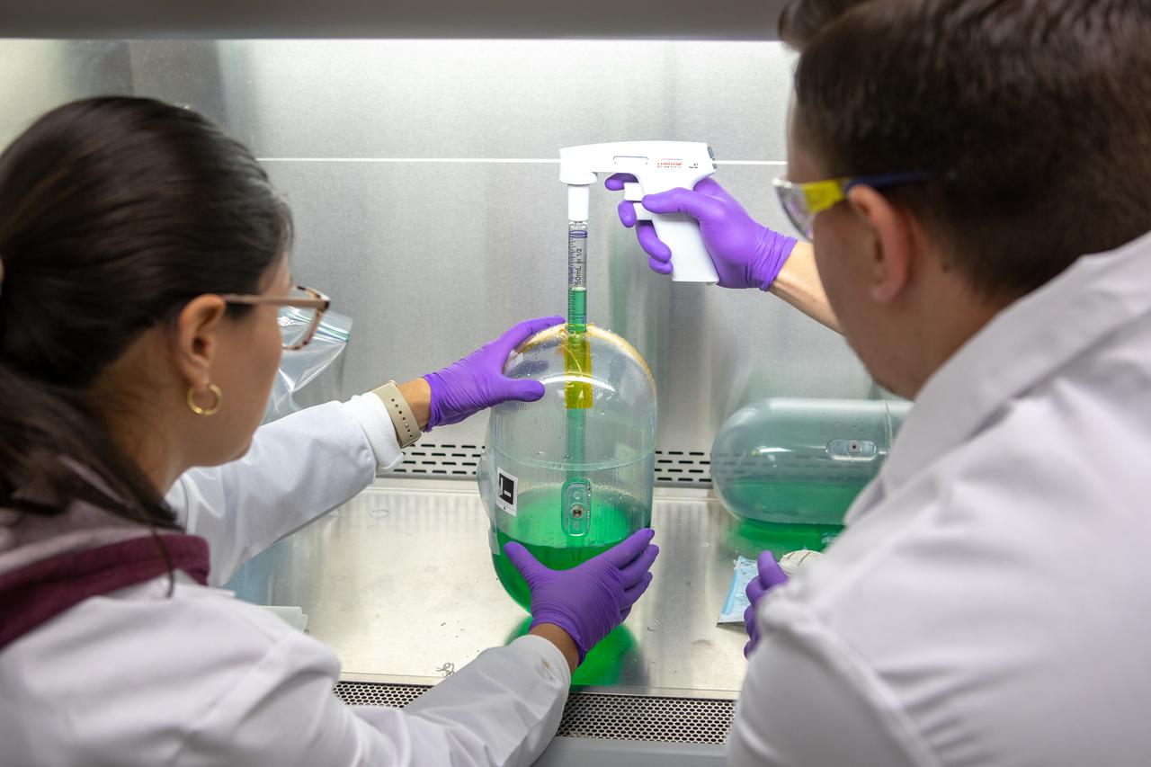
Kennedy Space Center’s Carolina Franco, Ph.D., left, and Jason Fischer collect samples from a water tank, filled with green dye, for a biological study in the Florida spaceport’s Neil Armstrong Operations and Checkout Building on Nov. 13, 2019. Two tanks have recently returned to Kennedy after spending the last five years on the International Space Station for an experiment to study slosh, or the movement of water, in a zero-gravity environment to help engineers predict the movement of propellant in rocket tanks. Kennedy’s Air and Water Revitalization lab is studying the water tanks to determine if there is, or was, any microbial growth within them. The results will help NASA determine whether clean water can be stored in space for long-duration missions, an essential component to keeping astronauts safe and healthy as the agency prepares for missions to the Moon and beyond to Mars.
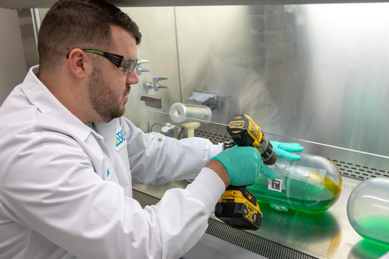
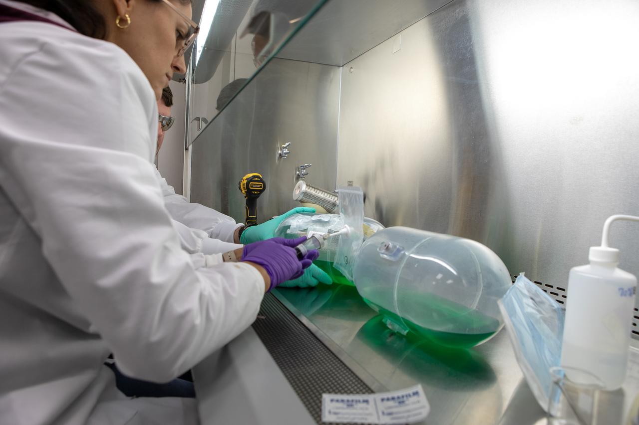
Kennedy Space Center’s Brint Bauer drills into a water tank, filled with green dye, in the Florida spaceport’s Neil Armstrong Operations and Checkout Building on Nov. 13, 2019. Two tanks have recently returned to Kennedy after spending the last five years on the International Space Station for an experiment to study slosh, or the movement of water, in a zero-gravity environment to help engineers predict the movement of propellant in rocket tanks. With the slosh experiment now concluded, Kennedy’s Air and Water Revitalization lab is studying the water tanks to determine if there is, or was, any microbial growth within them. The results will help NASA determine whether clean water can be stored in space for long-duration missions, an essential component to keeping astronauts safe and healthy as the agency prepares for missions to the Moon and beyond to Mars.
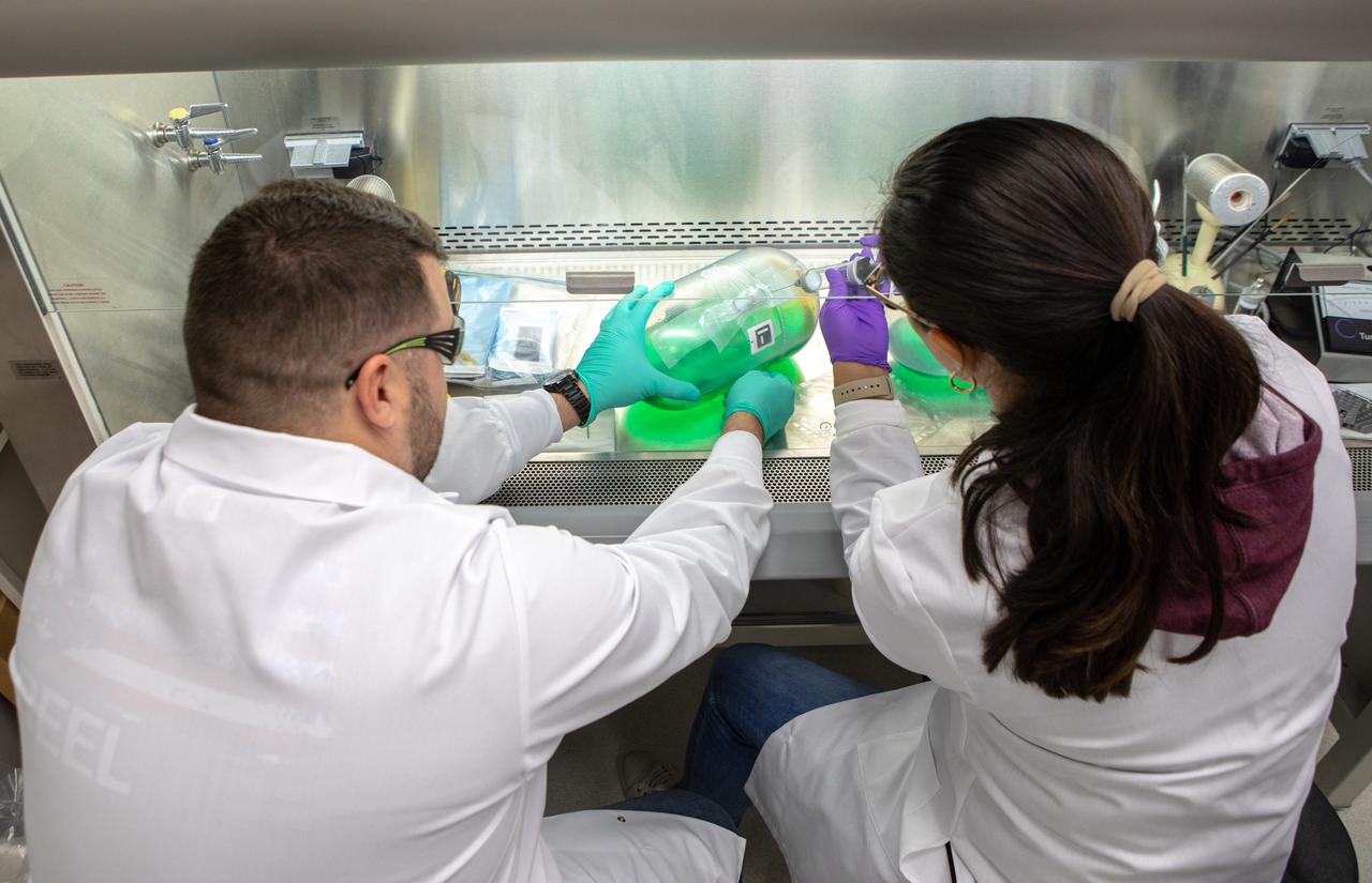
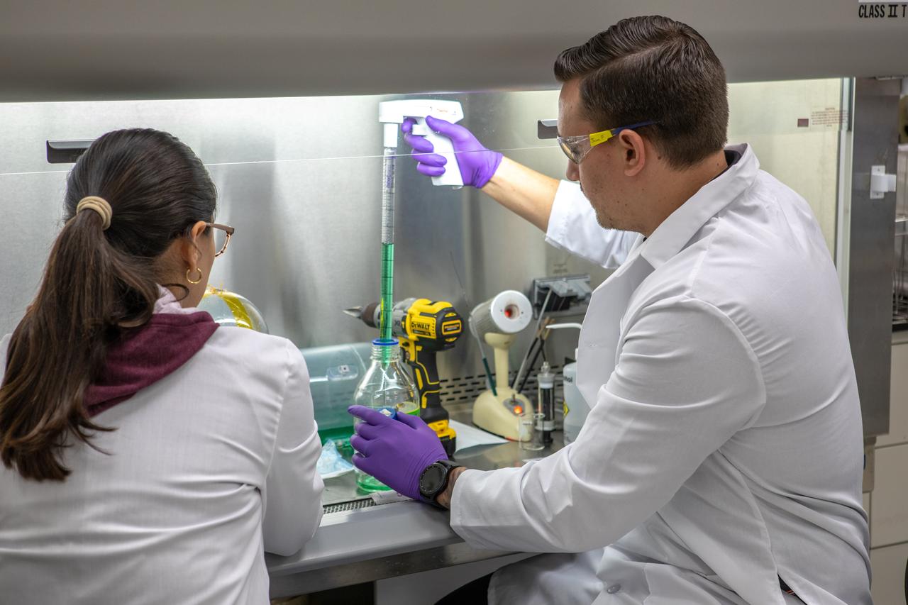
Kennedy Space Center’s Brint Bauer, left, and Carolina Franco, Ph.D., collect samples from a water tank, filled with green dye, for a biological study in the Florida spaceport’s Neil Armstrong Operations and Checkout Building on Nov. 13, 2019. Two tanks have recently returned to Kennedy after spending the last five years on the International Space Station for an experiment to study slosh, or the movement of water, in a zero-gravity environment to help engineers predict the movement of propellant in rocket tanks. Kennedy’s Air and Water Revitalization lab is studying the water tanks to determine if there is, or was, any microbial growth within them. The results will help NASA determine whether clean water can be stored in space for long-duration missions, an essential component to keeping astronauts safe and healthy as the agency prepares for missions to the Moon and beyond to Mars.
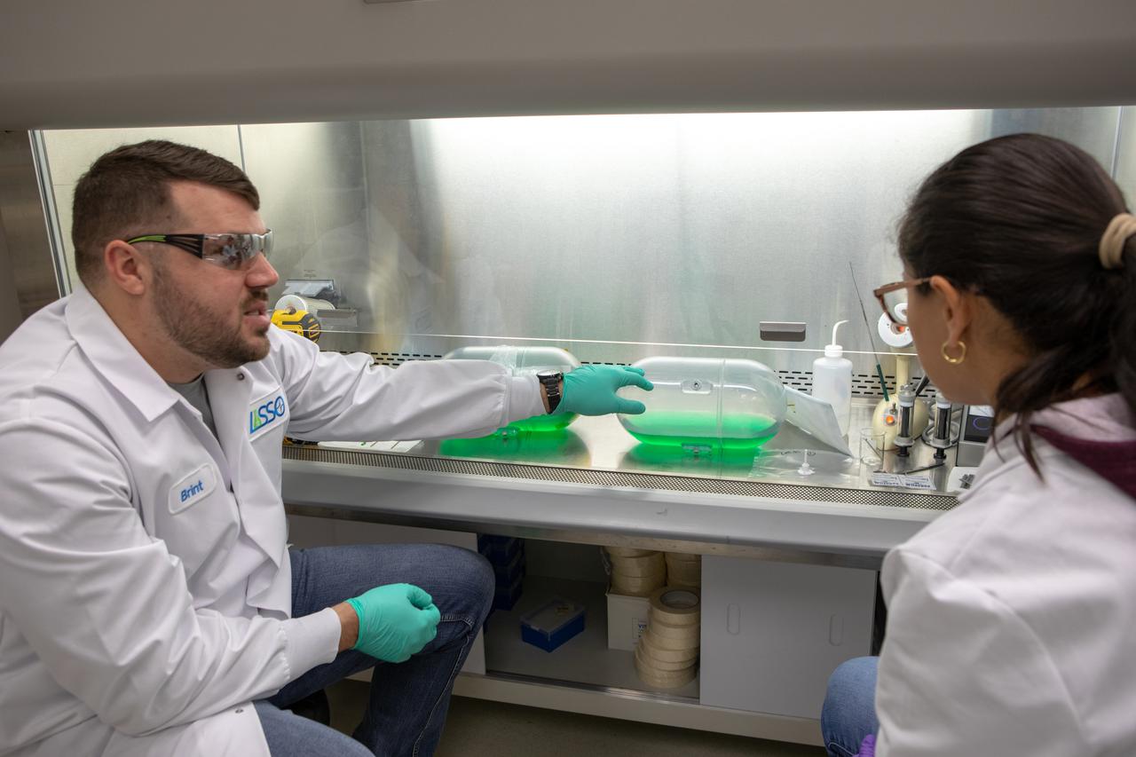
Kennedy Space Center’s Brint Bauer, left, and Carolina Franco, Ph.D., conduct a biological study on two tanks of water, filled with green dye, in the Florida spaceport’s Neil Armstrong Operations and Checkout Building on Nov. 13, 2019. The tanks have recently returned to Kennedy after spending the last five years on the International Space Station for an experiment to study slosh, or the movement of water, in a zero-gravity environment to help engineers predict the movement of propellant in rocket tanks. Kennedy’s Air and Water Revitalization lab is studying the water tanks to determine if there is, or was, any microbial growth within them. The results will help NASA determine whether clean water can be stored in space for long-duration missions, an essential component to keeping astronauts safe and healthy as the agency prepares for missions to the Moon and beyond to Mars.
A Kennedy Space Center employee collects samples from a water tank, filled with green dye, for a biological study in the Florida spaceport’s Neil Armstrong Operations and Checkout Building on Nov. 13, 2019. Two tanks have recently returned to Kennedy after spending the last five years on the International Space Station for an experiment to study slosh, or the movement of water, in a zero-gravity environment to help engineers predict the movement of propellant in rocket tanks. With the slosh experiment now concluded, Kennedy’s Air and Water Revitalization lab is studying the water tanks to determine if there is, or was, any microbial growth within them. The results will help NASA determine whether clean water can be stored in space for long-duration missions, an essential component to keeping astronauts safe and healthy as the agency prepares for missions to the Moon and beyond to Mars.
Kennedy Space Center’s Christina Khodadad, Ph.D., left, and Jason Fischer hold samples of water in the Florida spaceport’s Neil Armstrong Operations and Checkout Building on Nov. 13, 2019. Two tanks of water have recently returned to Kennedy after spending the last five years on the International Space Station for an experiment to study slosh, or the movement of water, in a zero-gravity environment to help engineers predict the movement of propellant in rocket tanks. Kennedy’s Air and Water Revitalization lab is studying the water tanks to determine if there is, or was, any microbial growth within them. The results will help NASA determine whether clean water can be stored in space for long-duration missions, an essential component to keeping astronauts safe and healthy as the agency prepares for missions to the Moon and beyond to Mars.
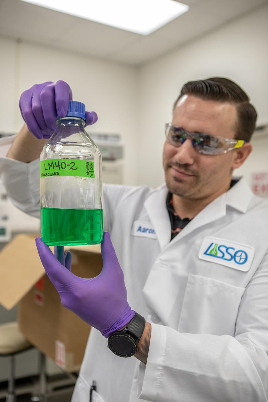
Kennedy Space Center’s Jason Fischer holds a sample of water in the Florida spaceport’s Neil Armstrong Operations and Checkout Building on Nov. 13, 2019. Two tanks of water have recently returned to Kennedy after spending the last five years on the International Space Station for an experiment to study slosh, or the movement of water, in a zero-gravity environment to help engineers predict the movement of propellant in rocket tanks. Kennedy’s Air and Water Revitalization lab is studying the water tanks to determine if there is, or was, any microbial growth within them. The results will help NASA determine whether clean water can be stored in space for long-duration missions, an essential component to keeping astronauts safe and healthy as the agency prepares for missions to the Moon and beyond to Mars.
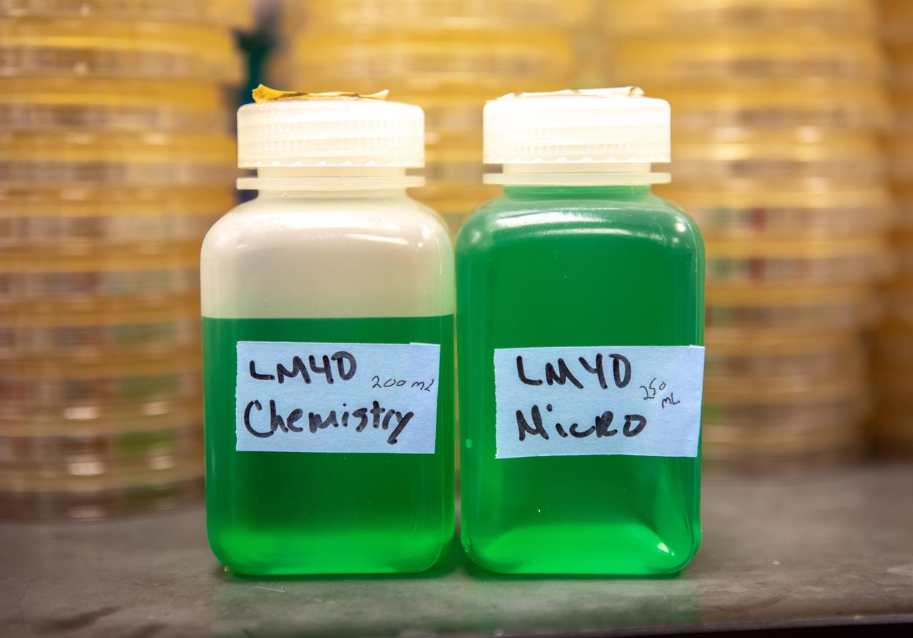
Samples of water, filled with green dye, gathered from two water tanks that have spent the past five years in space, are photographed inside the Neil Armstrong Operations and Checkout Building at NASA’s Kennedy Space Center in Florida on Nov. 13, 2019. The tanks were first sent to the International Space Station in 2014 to study slosh, or the movement of water, in a zero-gravity environment to help engineers predict the movement of propellant in rocket tanks. With the slosh experiment now concluded and the tanks recently returned to Kennedy, they are being utilized for a biological study to determine if there is, or was, any microbial growth within them. The results will help NASA determine whether clean water can be stored in space for long-duration missions, an essential component to keeping astronauts safe and healthy as the agency prepares for missions to the Moon and beyond to Mars.
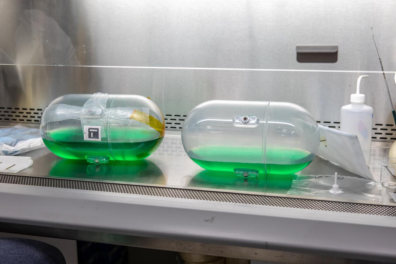
Researchers from NASA’s Kennedy Space Center Air and Water Revitalization lab are studying two tanks, containing water with green dye, inside the Neil Armstrong Operations and Checkout Building in Florida on Nov. 13, 2019. The tanks have recently returned to Kennedy after remaining on the International Space Station for the past five years, originally sent to space to study slosh – the movement of water – in a zero-gravity environment to help engineers predict the movement of propellant in rocket tanks. With the slosh experiment now concluded, the tanks are being examined to determine if there is, or was, any microbial growth within them. The results will help NASA determine whether clean water can be stored in space for long-duration missions, an essential component to keeping astronauts safe and healthy as the agency prepares for missions to the Moon and beyond to Mars.
A Kennedy Space Center employee collects samples from a water tank, filled with green dye, for a biological study in the Florida spaceport’s Neil Armstrong Operations and Checkout Building on Nov. 13, 2019. Two tanks have recently returned to Kennedy after spending the last five years on the International Space Station for an experiment to study slosh, or the movement of water, in a zero-gravity environment to help engineers predict the movement of propellant in rocket tanks. With the slosh experiment now concluded, the tanks are being utilized to determine if there is, or was, any microbial growth within them. The results will help NASA determine whether clean water can be stored in space for long-duration missions, an essential component to keeping astronauts safe and healthy as the agency prepares for missions to the Moon and beyond to Mars.
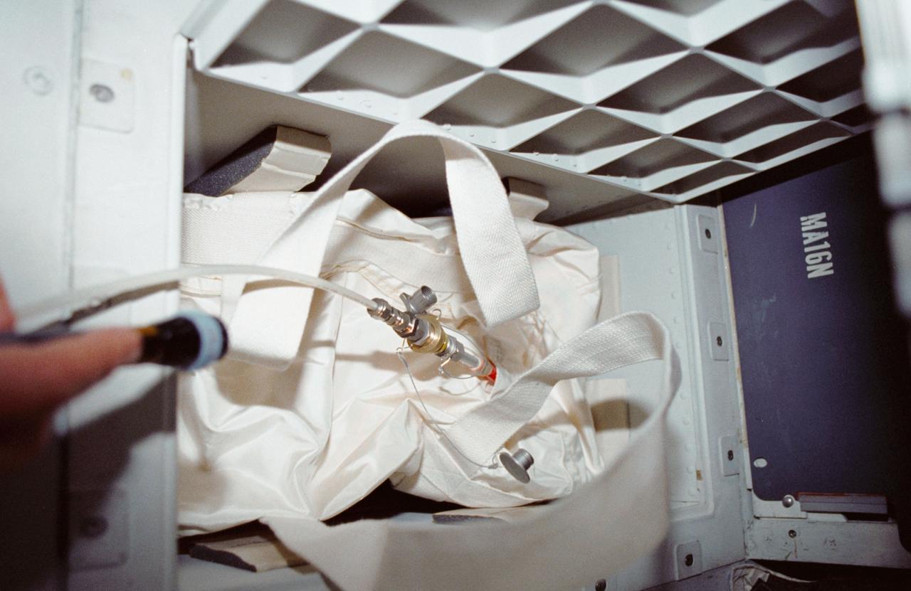
STS035-12-005 (2-10 Dec 1990) --- During STS-35, middeck stowage volume G and a contingency water container (CWC) were utilized to remedy a problem onboard Columbia, Orbiter Vehicle (OV) 102. A hose connecting OV-102's waste water system to the CWC was used in order to bypass a suspected clog in the line from the waste water tank to the exit nozzle. On flight day seven, Pilot Guy S. Gardner carried out an inflight maintenance (IFM) procedure by connecting a spare hose from the line to the container. The CWC is a rubber-lined duffle bag that holds about 95 pounds of water and is used in situations where water cannot be dumped overboard normally.
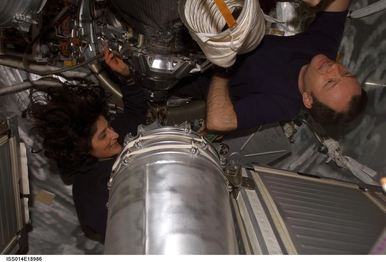
ISS014-E-18986 (5 April 2007) --- Astronauts Michael E. Lopez-Alegria (right), Expedition 14 commander and NASA space station science officer, and Sunita L. Williams, flight engineer, work with water tanks in the Progress 24 spacecraft docked to the International Space Station.
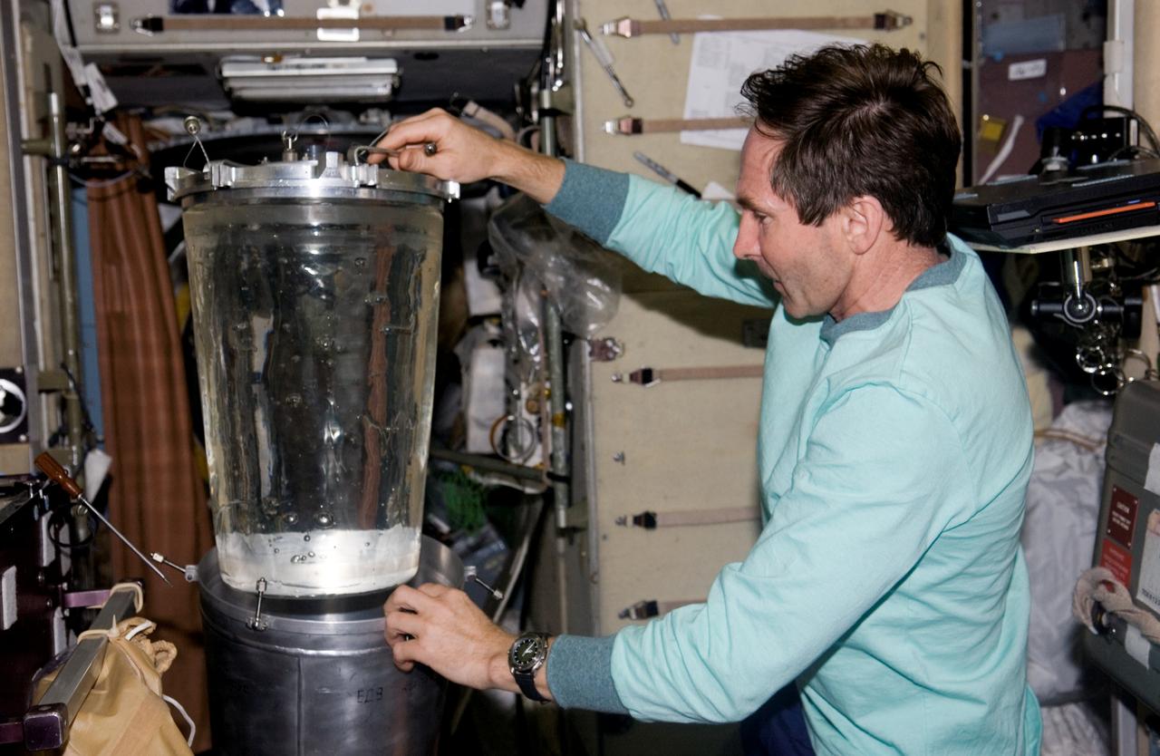
ISS012-E-06290 (3 November 2005) --- Cosmonaut Valery I. Tokarev, Expedition 12 flight engineer representing Russia's Federal Space Agency, performs a water transfer from Progress Tanks 1 and 2 to the Russian EDV water container in the Zvezda Service Module of the International Space Station.
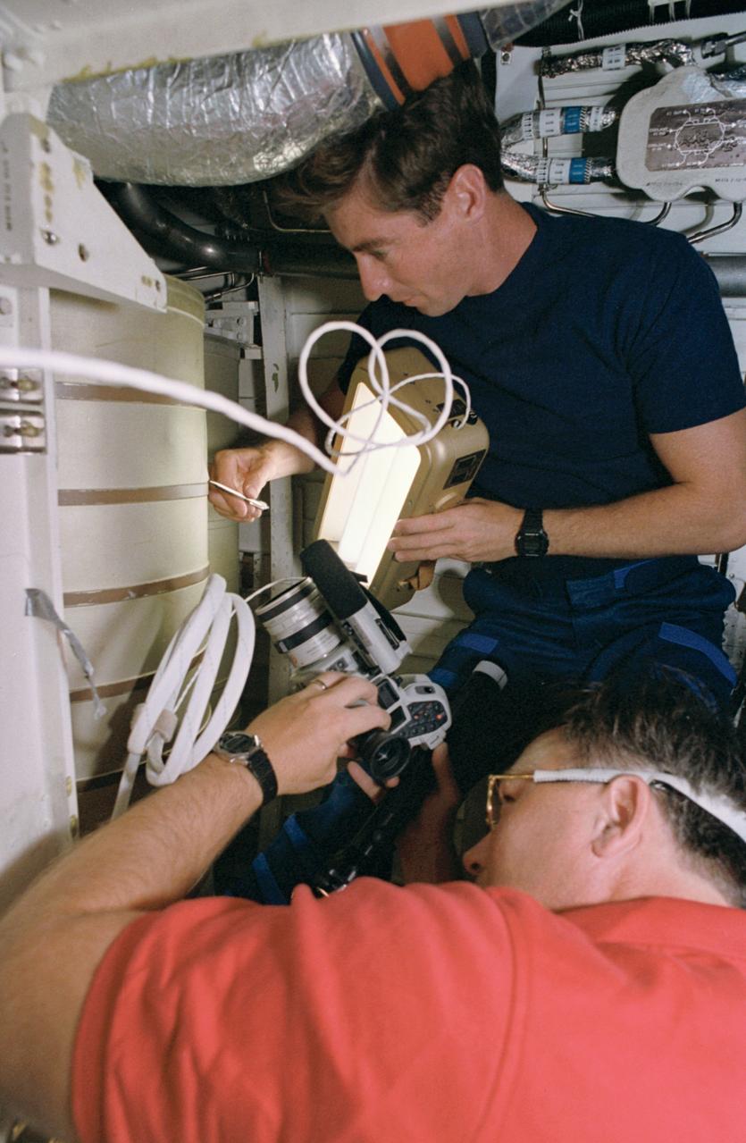
STS055-39-036 (26 April-6 May 1993) --- Astronaut Terence T. (Tom) Henricks, pilot, uses a spotlight and pen to point out a possible problem area on a waste water tank in the bilge area below Columbia's middeck. Astronaut Jerry L. Ross, payload commander, records the activity with a camera.
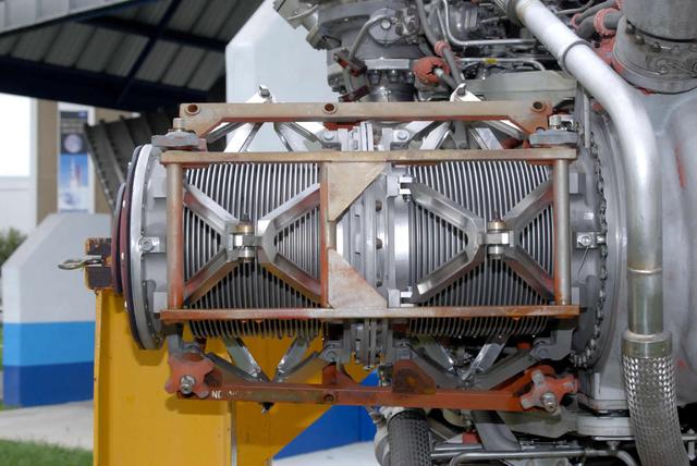
Stennis Space Center engineers are preparing to conduct water tests on an updated version of the scissors duct component of the J-2X engine. Measuring about 2 feet long and about 8 inches in diameter, the duct on the J-2X predecessor, the J-2, connected its fuel turbo pumps to the flight vehicle's upper stage run tanks. According to NASA's J-2X project manager at SSC, Gary Benton, the water tests should establish the limits of the duct's ability to withstand vibration.
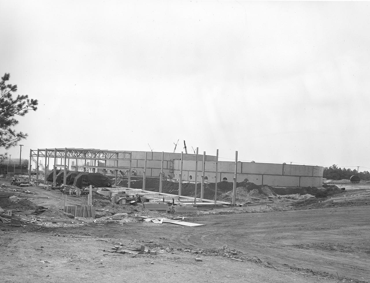
At its founding, the Marshall Space Flight Center (MSFC) inherited the Army’s Jupiter and Redstone test stands, but much larger facilities were needed for the giant stages of the Saturn V. From 1960 to 1964, the existing stands were remodeled and a sizable new test area was developed. The new comprehensive test complex for propulsion and structural dynamics was unique within the nation and the free world, and they remain so today because they were constructed with foresight to meet the future as well as on going needs. Construction of the S-IC Static test stand complex began in 1961 in the west test area of MSFC, and was completed in 1964. The S-IC static test stand was designed to develop and test the 138-ft long and 33-ft diameter Saturn V S-IC first stage, or booster stage, weighing in at 280,000 pounds. Required to hold down the brute force of a 7,500,000-pound thrust produced by 5 F-1 engines, the S-IC static test stand was designed and constructed with the strength of hundreds of tons of steel and 12,000,000 pounds of cement, planted down to bedrock 40 feet below ground level. The foundation walls, constructed with concrete and steel, are 4 feet thick. The base structure consists of four towers with 40-foot-thick walls extending upward 144 feet above ground level. The structure was topped by a crane with a 135-foot boom. With the boom in the upright position, the stand was given an overall height of 405 feet, placing it among the highest structures in Alabama at the time. In addition to the stand itself, related facilities were constructed during this time. Built to the northeast of the stand was a newly constructed Pump House. Its function was to provide water to the stand to prevent melting damage during testing. The water was sprayed through small holes in the stand’s 1900 ton flame deflector at the rate of 320,000 gallons per minute. This close up photograph, taken September 5, 1963, shows the ground level frame work for the Pump House and its massive round water storage tanks.
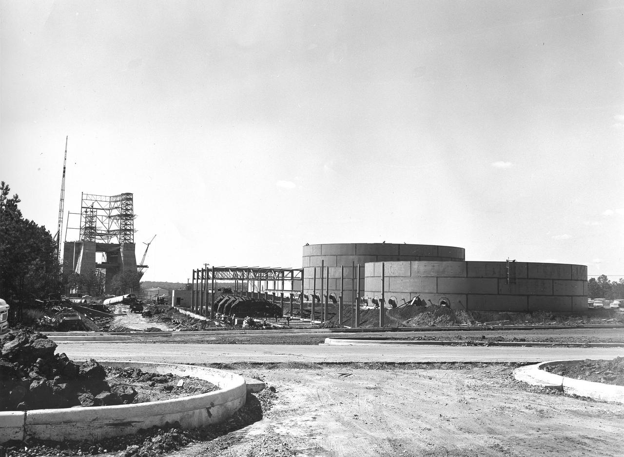
At its founding, the Marshall Space Flight Center (MSFC) inherited the Army’s Jupiter and Redstone test stands, but much larger facilities were needed for the giant stages of the Saturn V. From 1960 to 1964, the existing stands were remodeled and a sizable new test area was developed. The new comprehensive test complex for propulsion and structural dynamics was unique within the nation and the free world, and they remain so today because they were constructed with foresight to meet the future as well as on going needs. Construction of the S-IC Static test stand complex began in 1961 in the west test area of MSFC, and was completed in 1964. The S-IC static test stand was designed to develop and test the 138-ft long and 33-ft diameter Saturn V S-IC first stage, or booster stage, weighing in at 280,000 pounds. Required to hold down the brute force of a 7,500,000-pound thrust produced by 5 F-1 engines, the S-IC static test stand was designed and constructed with the strength of hundreds of tons of steel and 12,000,000 pounds of cement, planted down to bedrock 40 feet below ground level. The foundation walls, constructed with concrete and steel, are 4 feet thick. The base structure consists of four towers with 40-foot-thick walls extending upward 144 feet above ground level. The structure was topped by a crane with a 135-foot boom. With the boom in the upright position, the stand was given an overall height of 405 feet, placing it among the highest structures in Alabama at the time. In addition to the stand itself, related facilities were constructed during this time. Built to the northeast of the stand was a newly constructed Pump House. Its function was to provide water to the stand to prevent melting damage during testing. The water was sprayed through small holes in the stand’s 1900 ton flame deflector at the rate of 320,000 gallons per minute. This photograph, taken September 25, 1963, depicts the construction progress of the Pump House and massive round water tanks on the right.
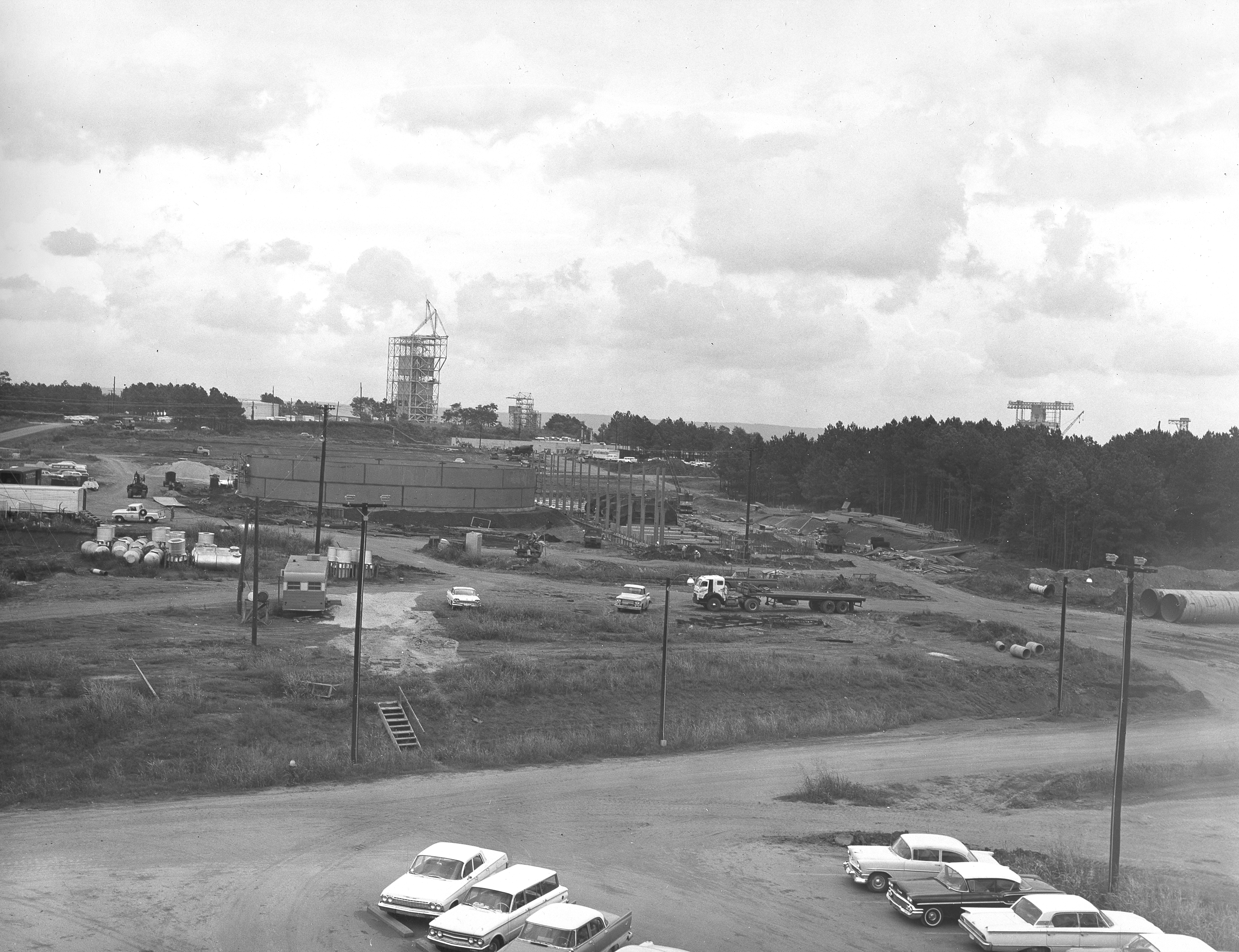
At its founding, the Marshall Space Flight Center (MSFC) inherited the Army’s Jupiter and Redstone test stands, but much larger facilities were needed for the giant stages of the Saturn V. From 1960 to 1964, the existing stands were remodeled and a sizable new test area was developed. The new comprehensive test complex for propulsion and structural dynamics was unique within the nation and the free world, and they remain so today because they were constructed with foresight to meet the future as well as on going needs. Construction of the S-IC Static test stand complex began in 1961 in the west test area of MSFC, and was completed in 1964. The S-IC static test stand was designed to develop and test the 138-ft long and 33-ft diameter Saturn V S-IC first stage, or booster stage, weighing in at 280,000 pounds. Required to hold down the brute force of a 7,500,000-pound thrust produced by 5 F-1 engines, the S-IC static test stand was designed and constructed with the strength of hundreds of tons of steel and 12,000,000 pounds of cement, planted down to bedrock 40 feet below ground level. The foundation walls, constructed with concrete and steel, are 4 feet thick. The base structure consists of four towers with 40-foot-thick walls extending upward 144 feet above ground level. The structure was topped by a crane with a 135-foot boom. With the boom in the upright position, the stand was given an overall height of 405 feet, placing it among the highest structures in Alabama at the time. In addition to the stand itself, related facilities were constructed during this time. Built to the northeast east was a newly constructed Pump House. Its function was to provide water to the stand to prevent melting damage during testing. The water was sprayed through small holes in the stand’s 1900 ton flame deflector at the rate of 320,000 gallons per minute. This photograph of the Pump House area was taken August 13, 1963. The massive round water storage tanks can be seen to the left of the Pump House.
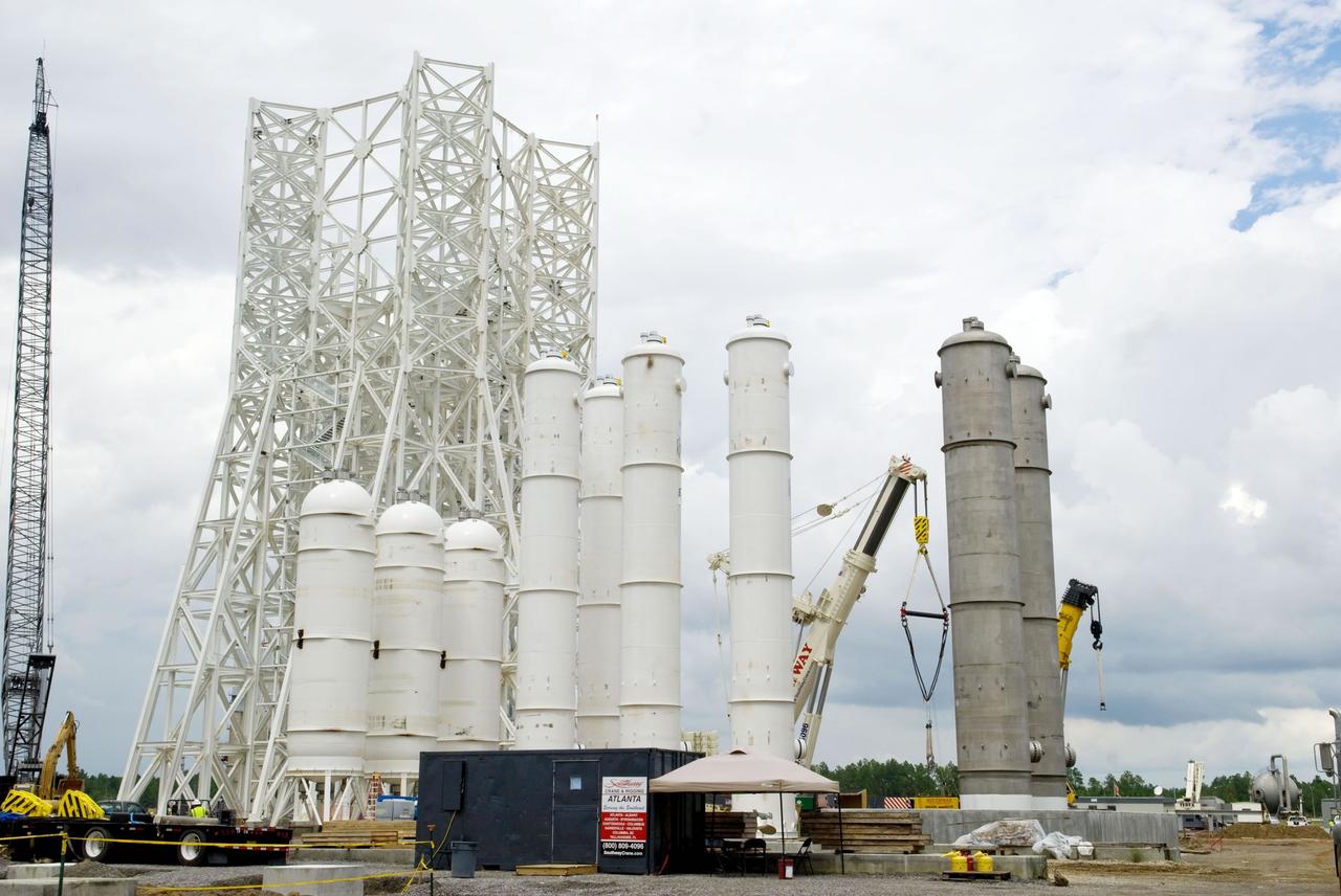
Construction of the A-3 Test Stand approaches another milestone with delivery and installation of water, isopropyl alcohol (IPA) and liquid oxygen (LOX) tanks. The three LOX tanks shown on the left and the two IPA tanks shown on the right are all 35,000 gallons each. The four water tanks in the center are 39,000 gallons each.

Photo shows how the Space Launch Sysetm (SLS) rocket liquid oxygen tank failed during a structural qualification test at NASA’s Marshall Space Flight Center in Huntsville, Alabama. The photos show both the water flowing from the tank as it ruptured and the resultant tear left in the tank when it buckled during the test. Engineers pushed the liquid oxygen structural test article to the limits on purpose. The tank is a test article that is identical to tanks that are part of the SLS core stage that will produce 2 million pounds of thrust to help launch the rocket on the Artemis missions to the Moon. During the test, hydraulic cylinders were then calibrated and positioned along the tank to apply millions of pounds of crippling force from all sides while engineers measured and recorded the effects of the launch and flight forces. For the test, water used to simulate the liquid oxygen flows out of the tank after it ruptures. The structural test campaign was conducted on the rocket to ensure the SLS rocket’s structure can endure the rigors of launch and safely send astronauts to the Moon on the Artemis missions. For more information: https://www.nasa.gov/exploration/systems/sls/nasa-completes-artemis-sls-structural-testing-campaign.html

Photo shows how the Space Launch Sysetm (SLS) rocket liquid oxygen tank failed during a structural qualification test at NASA’s Marshall Space Flight Center in Huntsville, Alabama. The photos show both the water flowing from the tank as it ruptured and the resultant tear left in the tank when it buckled during the test. Engineers pushed the liquid oxygen structural test article to the limits on purpose. The tank is a test article that is identical to tanks that are part of the SLS core stage that will produce 2 million pounds of thrust to help launch the rocket on the Artemis missions to the Moon. During the test, hydraulic cylinders were then calibrated and positioned along the tank to apply millions of pounds of crippling force from all sides while engineers measured and recorded the effects of the launch and flight forces. For the test, water used to simulate the liquid oxygen flows out of the tank after it ruptures. The structural test campaign was conducted on the rocket to ensure the SLS rocket’s structure can endure the rigors of launch and safely send astronauts to the Moon on the Artemis missions. For more information: https://www.nasa.gov/exploration/systems/sls/nasa-completes-artemis-sls-structural-testing-campaign.html

Photo shows how the Space Launch Sysetm (SLS) rocket liquid oxygen tank failed during a structural qualification test at NASA’s Marshall Space Flight Center in Huntsville, Alabama. The photos show both the water flowing from the tank as it ruptured and the resultant tear left in the tank when it buckled during the test. Engineers pushed the liquid oxygen structural test article to the limits on purpose. The tank is a test article that is identical to tanks that are part of the SLS core stage that will produce 2 million pounds of thrust to help launch the rocket on the Artemis missions to the Moon. During the test, hydraulic cylinders were then calibrated and positioned along the tank to apply millions of pounds of crippling force from all sides while engineers measured and recorded the effects of the launch and flight forces. For the test, water used to simulate the liquid oxygen flows out of the tank after it ruptures. The structural test campaign was conducted on the rocket to ensure the SLS rocket’s structure can endure the rigors of launch and safely send astronauts to the Moon on the Artemis missions. For more information: https://www.nasa.gov/exploration/systems/sls/nasa-completes-artemis-sls-structural-testing-campaign.html

Photo shows how the Space Launch Sysetm (SLS) rocket liquid oxygen tank failed during a structural qualification test at NASA’s Marshall Space Flight Center in Huntsville, Alabama. The photos show both the water flowing from the tank as it ruptured and the resultant tear left in the tank when it buckled during the test. Engineers pushed the liquid oxygen structural test article to the limits on purpose. The tank is a test article that is identical to tanks that are part of the SLS core stage that will produce 2 million pounds of thrust to help launch the rocket on the Artemis missions to the Moon. During the test, hydraulic cylinders were then calibrated and positioned along the tank to apply millions of pounds of crippling force from all sides while engineers measured and recorded the effects of the launch and flight forces. For the test, water used to simulate the liquid oxygen flows out of the tank after it ruptures. The structural test campaign was conducted on the rocket to ensure the SLS rocket’s structure can endure the rigors of launch and safely send astronauts to the Moon on the Artemis missions. For more information: https://www.nasa.gov/exploration/systems/sls/nasa-completes-artemis-sls-structural-testing-campaign.html
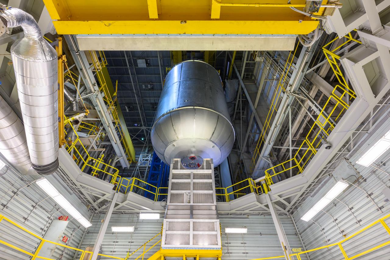
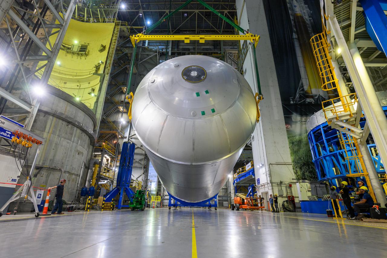
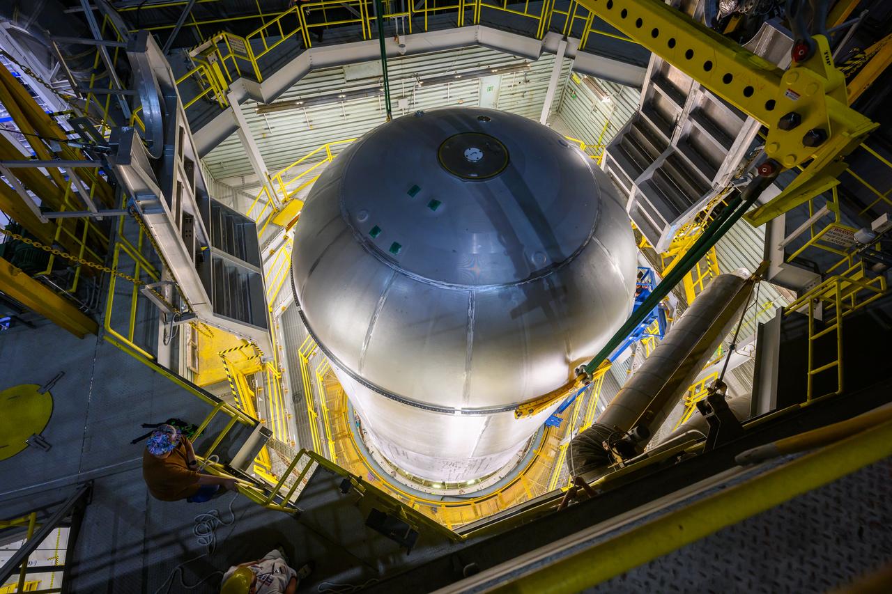
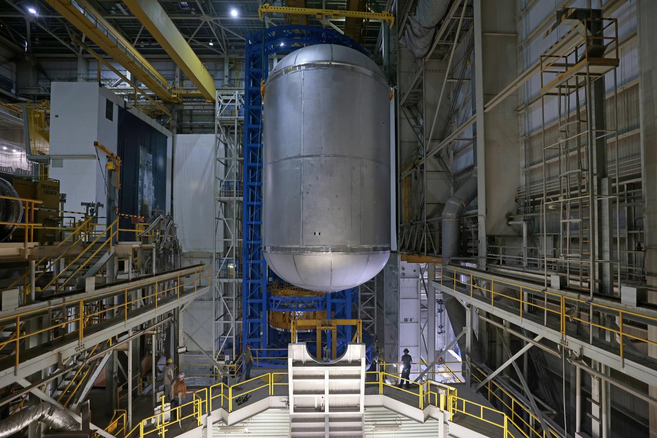
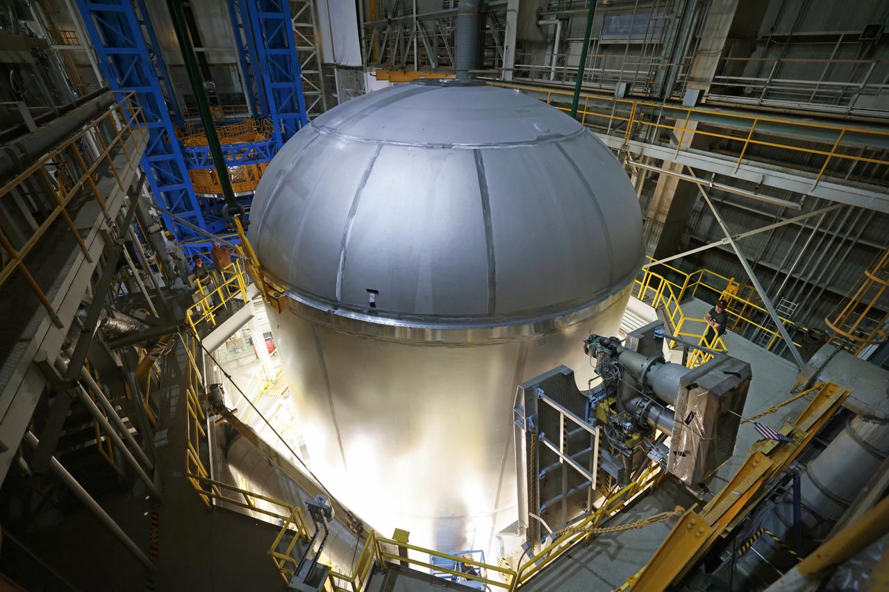
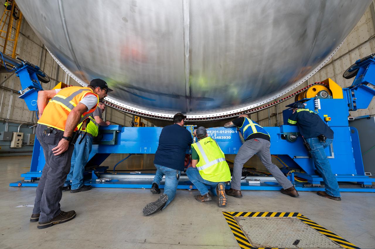
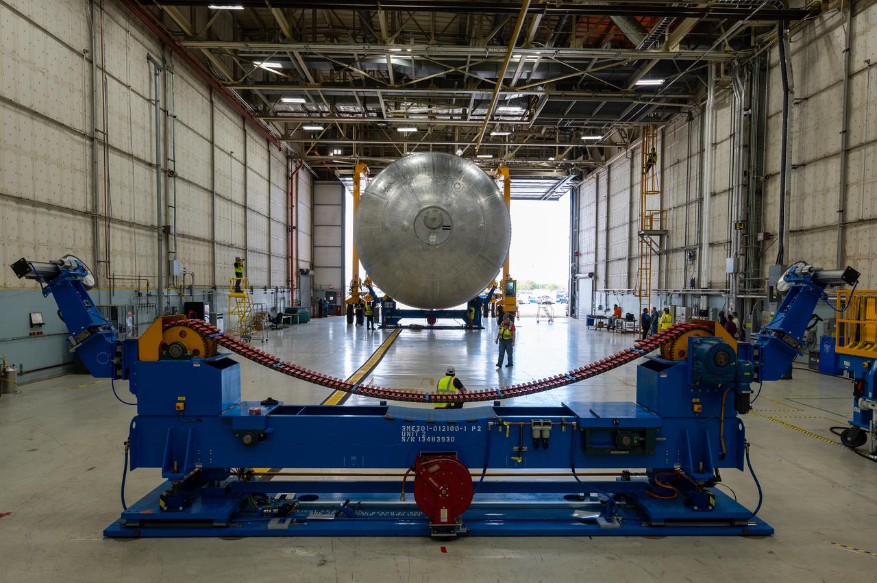
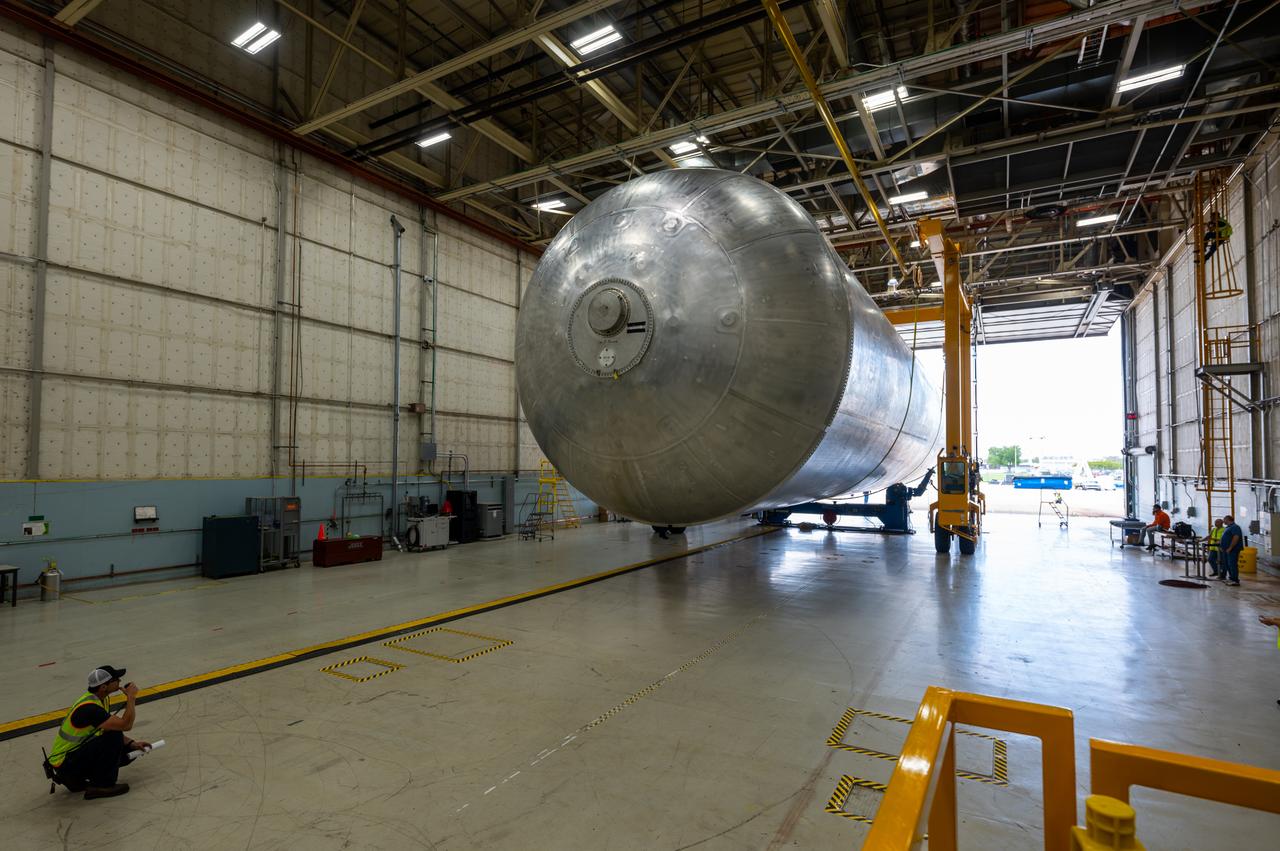
Teams at NASA’s Michoud Assembly Facility in New Orleans successfully completed hydrostatic proof testing of the core stage liquid oxygen tank for the agency’s Artemis III mission. The non-destructive evaluation method tests the structural integrity of the tank’s welds by filling the tank with water, simulating the propellant used during launch. The hardware was then moved to an adjacent cell for internal cleaning. Next, the tank will be readied for primer and application of its thermal protection system. The propellant tank is one of five major elements that make up the 212-foot-tall rocket stage. The core stage, along with its four RS-25 engines, produce two million pounds of thrust to help launch NASA’s Orion spacecraft, astronauts, and supplies beyond Earth’s orbit and to the lunar surface for Artemis.
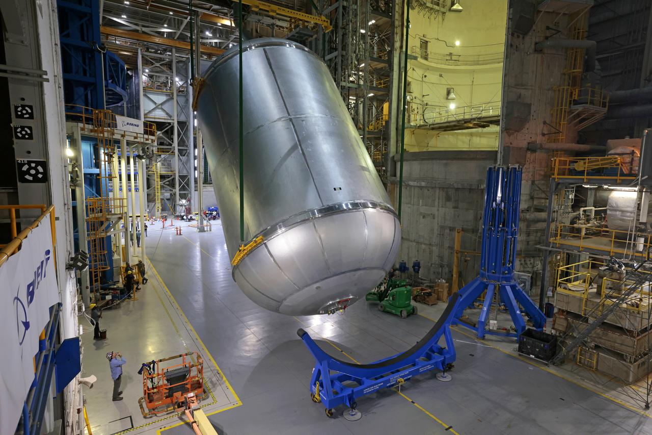
Teams at NASA’s Michoud Assembly Facility in New Orleans successfully completed hydrostatic proof testing of the core stage liquid oxygen tank for the agency’s Artemis III mission. The non-destructive evaluation method tests the structural integrity of the tank’s welds by filling the tank with water, simulating the propellant used during launch. The hardware was then moved to an adjacent cell for internal cleaning. Next, the tank will be readied for primer and application of its thermal protection system. The propellant tank is one of five major elements that make up the 212-foot-tall rocket stage. The core stage, along with its four RS-25 engines, produce two million pounds of thrust to help launch NASA’s Orion spacecraft, astronauts, and supplies beyond Earth’s orbit and to the lunar surface for Artemis. Image credit: NASA/Michael DeMocker
Teams at NASA’s Michoud Assembly Facility in New Orleans successfully completed hydrostatic proof testing of the core stage liquid oxygen tank for the agency’s Artemis III mission. The non-destructive evaluation method tests the structural integrity of the tank’s welds by filling the tank with water, simulating the propellant used during launch. The hardware was then moved to an adjacent cell for internal cleaning. Next, the tank will be readied for primer and application of its thermal protection system. The propellant tank is one of five major elements that make up the 212-foot-tall rocket stage. The core stage, along with its four RS-25 engines, produce two million pounds of thrust to help launch NASA’s Orion spacecraft, astronauts, and supplies beyond Earth’s orbit and to the lunar surface for Artemis.
Teams at NASA’s Michoud Assembly Facility in New Orleans successfully completed hydrostatic proof testing of the core stage liquid oxygen tank for the agency’s Artemis III mission. The non-destructive evaluation method tests the structural integrity of the tank’s welds by filling the tank with water, simulating the propellant used during launch. The hardware was then moved to an adjacent cell for internal cleaning. Next, the tank will be readied for primer and application of its thermal protection system. The propellant tank is one of five major elements that make up the 212-foot-tall rocket stage. The core stage, along with its four RS-25 engines, produce two million pounds of thrust to help launch NASA’s Orion spacecraft, astronauts, and supplies beyond Earth’s orbit and to the lunar surface for Artemis.
Teams at NASA’s Michoud Assembly Facility in New Orleans successfully completed hydrostatic proof testing of the core stage liquid oxygen tank for the agency’s Artemis III mission. The non-destructive evaluation method tests the structural integrity of the tank’s welds by filling the tank with water, simulating the propellant used during launch. The hardware was then moved to an adjacent cell for internal cleaning. Next, the tank will be readied for primer and application of its thermal protection system. The propellant tank is one of five major elements that make up the 212-foot-tall rocket stage. The core stage, along with its four RS-25 engines, produce two million pounds of thrust to help launch NASA’s Orion spacecraft, astronauts, and supplies beyond Earth’s orbit and to the lunar surface for Artemis. Image credit: NASA/Michael DeMocker
Teams at NASA’s Michoud Assembly Facility in New Orleans successfully completed hydrostatic proof testing of the core stage liquid oxygen tank for the agency’s Artemis III mission. The non-destructive evaluation method tests the structural integrity of the tank’s welds by filling the tank with water, simulating the propellant used during launch. The hardware was then moved to an adjacent cell for internal cleaning. Next, the tank will be readied for primer and application of its thermal protection system. The propellant tank is one of five major elements that make up the 212-foot-tall rocket stage. The core stage, along with its four RS-25 engines, produce two million pounds of thrust to help launch NASA’s Orion spacecraft, astronauts, and supplies beyond Earth’s orbit and to the lunar surface for Artemis. Image credit: NASA/Michael DeMocker
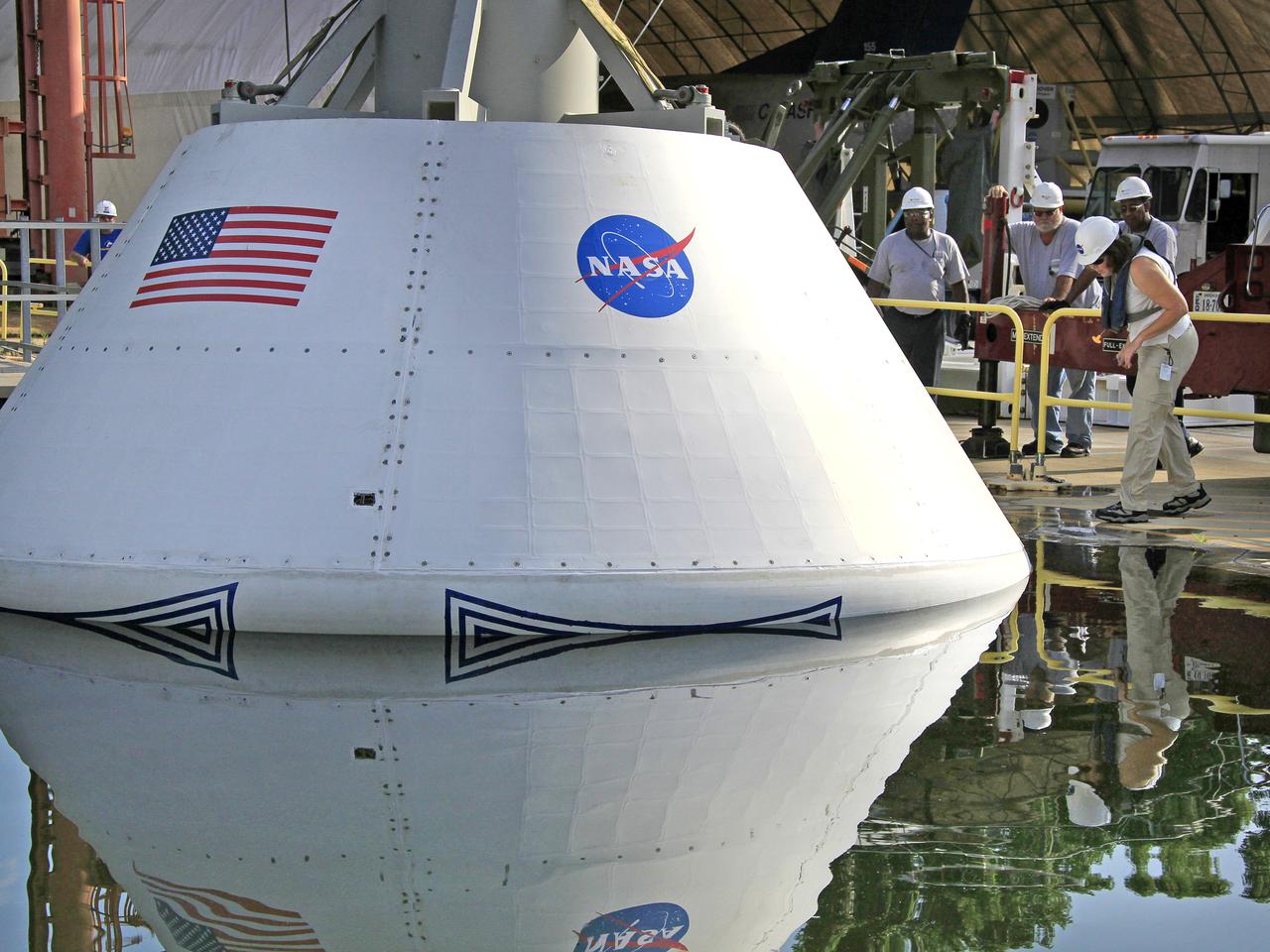
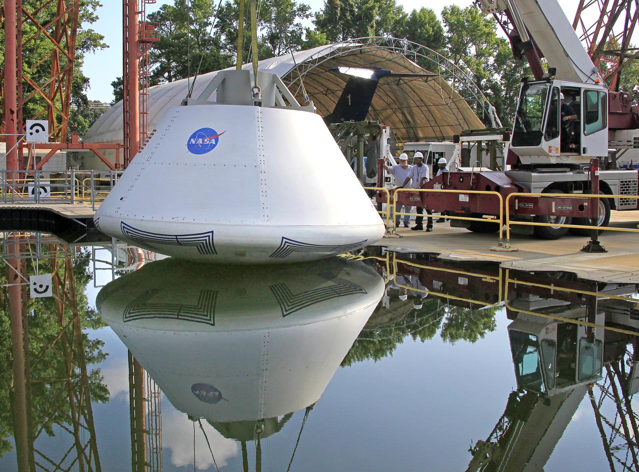
The Orion Test Capsule spent 4 hour in the water tank under NASA Langley's gantry to prove it is ready for the open water recovery test at Norfolk Naval Station.
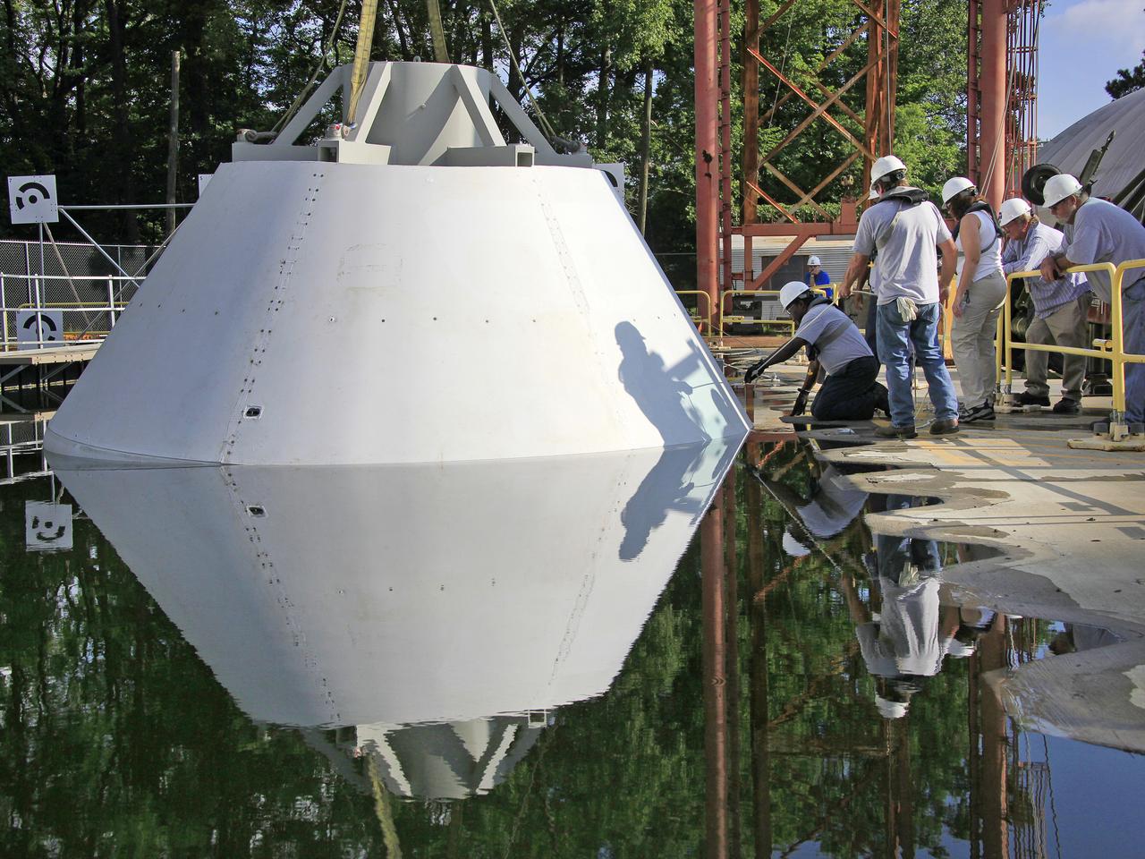
The Orion Test Capsule spent 4 hour in the water tank under NASA Langley's gantry to prove it is ready for the open water recovery test at Norfolk Naval Station.
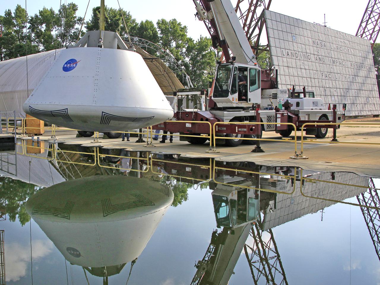
The Orion Test Capsule spent 4 hour in the water tank under NASA Langley's gantry to prove it is ready for the open water recovery test at Norfolk Naval Station.
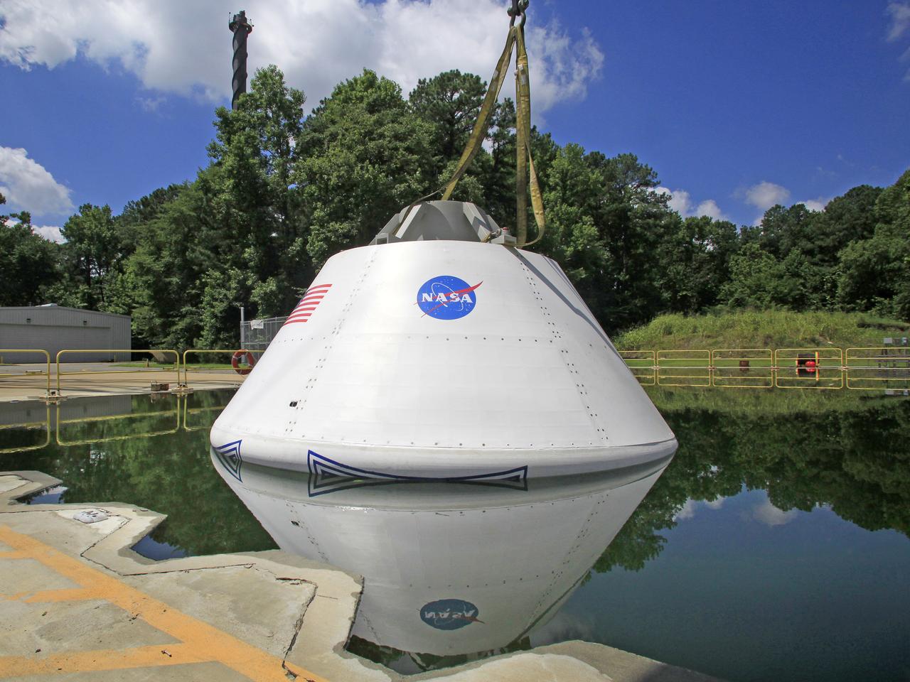
The Orion Test Capsule spent 4 hour in the water tank under NASA Langley's gantry to prove it is ready for the open water recovery test at Norfolk Naval Station.
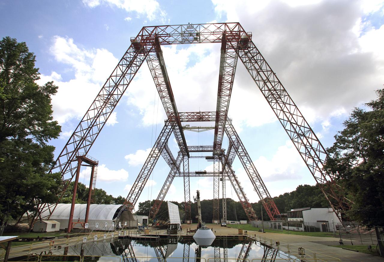
The Orion Test Capsule spent 4 hour in the water tank under NASA Langley's gantry to prove it is ready for the open water recovery test at Norfolk Naval Station.
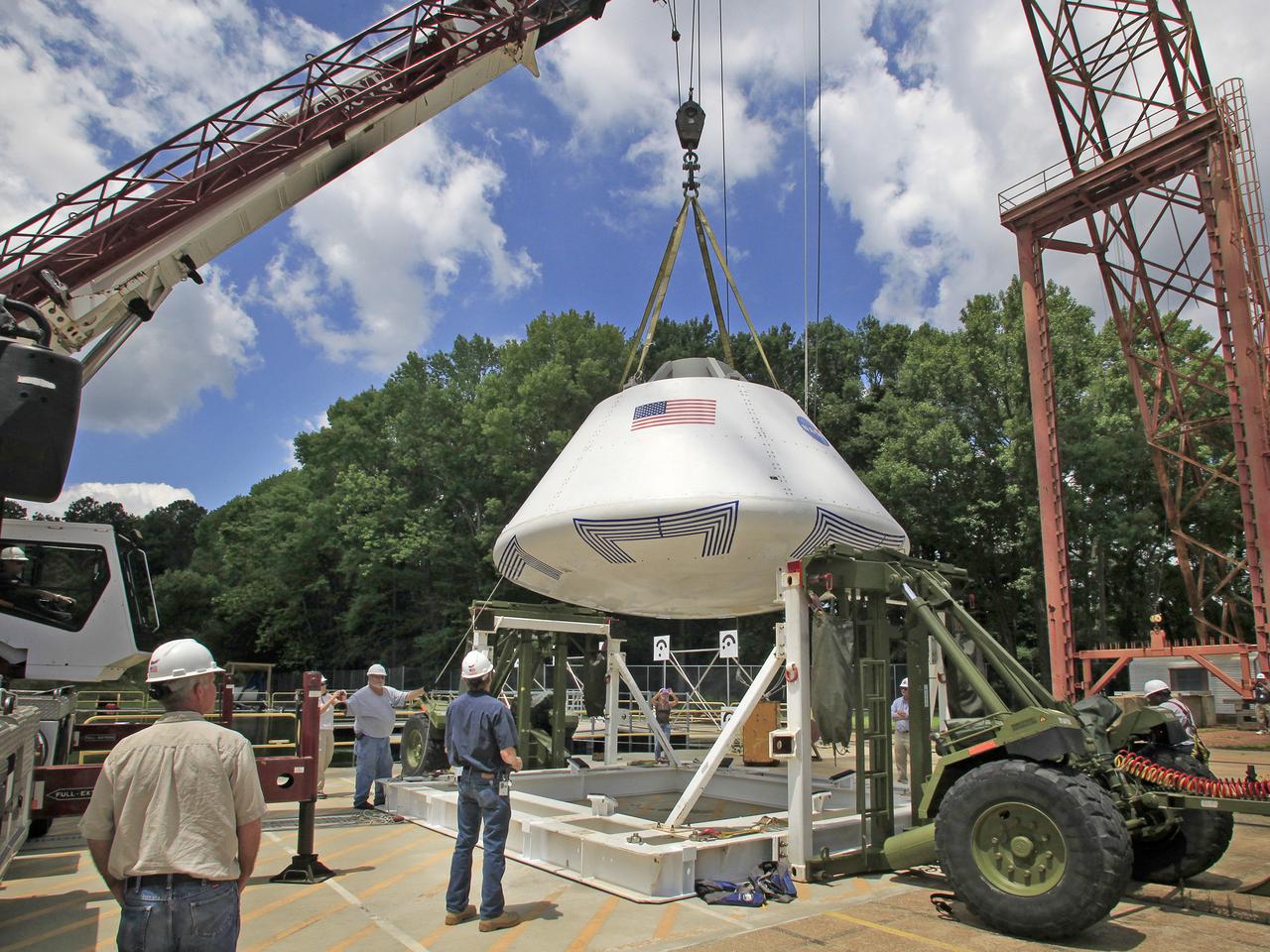
The Orion Test Capsule spent 4 hour in the water tank under NASA Langley's gantry to prove it is ready for the open water recovery test at Norfolk Naval Station.
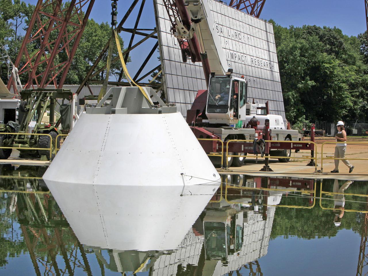
The Orion Test Capsule spent 4 hour in the water tank under NASA Langley's gantry to prove it is ready for the open water recovery test at Norfolk Naval Station.
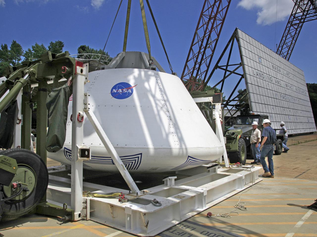
The Orion Test Capsule spent 4 hour in the water tank under NASA Langley's gantry to prove it is ready for the open water recovery test at Norfolk Naval Station.
The Orion Test Capsule spent 4 hour in the water tank under NASA Langley's gantry to prove it is ready for the open water recovery test at Norfolk Naval Station.
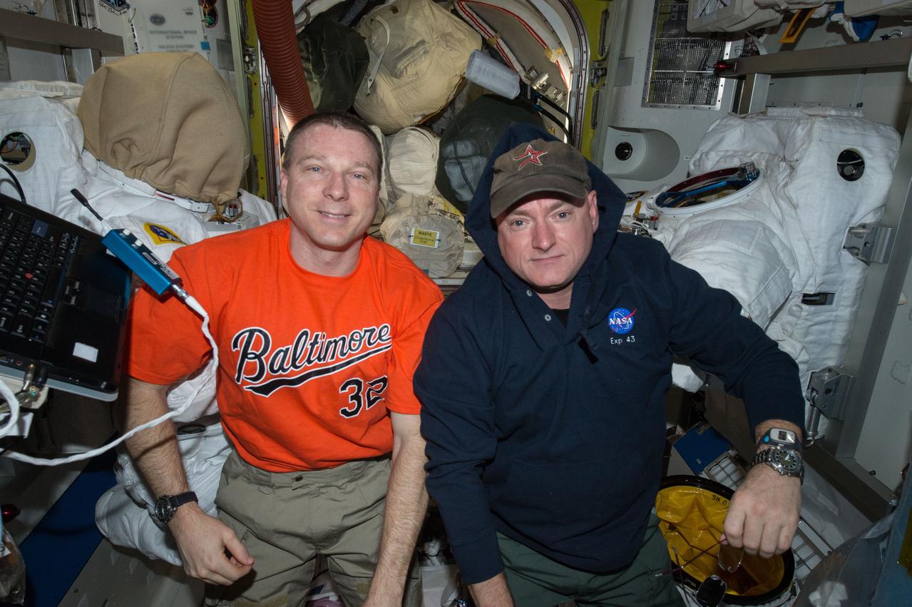
ISS043E087403 (04/06/2015) --- NASA astronauts Terry Virts (left) and Scott Kelly are seen here inside the station’s Quest airlock. The pair were performing routine maintenance activities on two of the International Space Station’s Extravehicular Mobility Units (EMU,) or spacesuits, seen in the background.
The core stage liquid hydrogen tank for the Artemis III mission completed proof testing, and technicians returned it to the main factory building at NASA’s Michoud Assembly Facility in New Orleans where it will undergo more outfitting. As part of proof testing, technicians apply a simple soap solution and check for leaks by observing any bubble formation on the welds. The technician removed the bubble solution with distilled water and then dried the area of application to prevent corrosion. To build the Space Launch System (SLS) rocket’s 130-foot core stage liquid hydrogen tank, engineers use robotic tools to weld five-barrel segments. This process results in a tank with around 1,900 feet, or more than six football fields, of welds that must be tested by hand. After the leak tests, the core stage lead, Boeing, pressurized the SLS tank to further ensure there were no leaks. After it passed proof testing, technicians moved the Artemis III liquid hydrogen tank to Michoud’s main factory. Soon, the technicians will prime and apply a foam-based thermal protection system that protects the tank during launch. Later, the tank will be joined with other parts of the core stage to form the entire 212-foot rocket stage with its four RS-25 engines that produce 2 million pounds of thrust to help launch the rocket. Artemis III will land the first astronauts on the lunar surface.
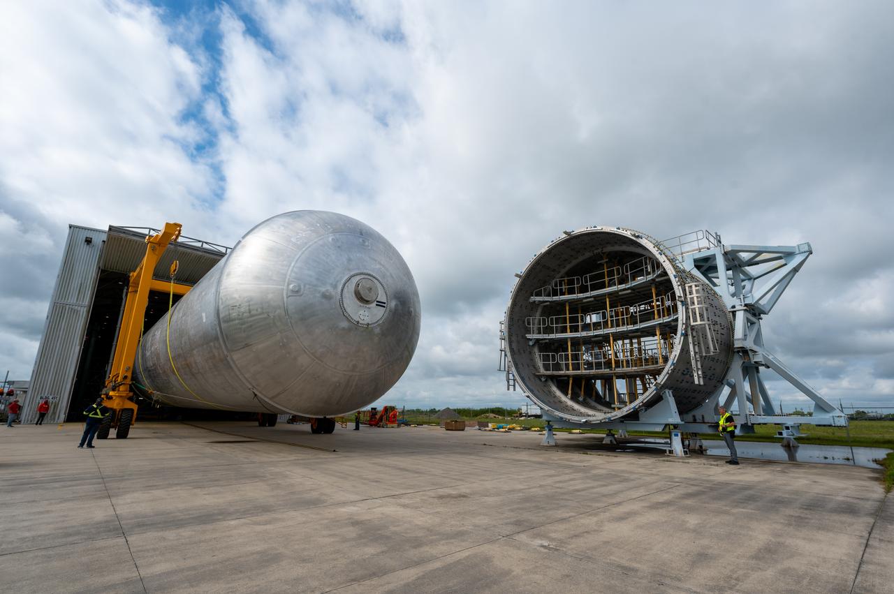
The core stage liquid hydrogen tank for the Artemis III mission completed proof testing, and technicians returned it to the main factory building at NASA’s Michoud Assembly Facility in New Orleans where it will undergo more outfitting. As part of proof testing, technicians apply a simple soap solution and check for leaks by observing any bubble formation on the welds. The technician removed the bubble solution with distilled water and then dried the area of application to prevent corrosion. To build the Space Launch System (SLS) rocket’s 130-foot core stage liquid hydrogen tank, engineers use robotic tools to weld five-barrel segments. This process results in a tank with around 1,900 feet, or more than six football fields, of welds that must be tested by hand. After the leak tests, the core stage lead, Boeing, pressurized the SLS tank to further ensure there were no leaks. After it passed proof testing, technicians moved the Artemis III liquid hydrogen tank to Michoud’s main factory. Soon, the technicians will prime and apply a foam-based thermal protection system that protects the tank during launch. Later, the tank will be joined with other parts of the core stage to form the entire 212-foot rocket stage with its four RS-25 engines that produce 2 million pounds of thrust to help launch the rocket. Artemis III will land the first astronauts on the lunar surface.
The core stage liquid hydrogen tank for the Artemis III mission completed proof testing, and technicians returned it to the main factory building at NASA’s Michoud Assembly Facility in New Orleans where it will undergo more outfitting. As part of proof testing, technicians apply a simple soap solution and check for leaks by observing any bubble formation on the welds. The technician removed the bubble solution with distilled water and then dried the area of application to prevent corrosion. To build the Space Launch System (SLS) rocket’s 130-foot core stage liquid hydrogen tank, engineers use robotic tools to weld five-barrel segments. This process results in a tank with around 1,900 feet, or more than six football fields, of welds that must be tested by hand. After the leak tests, the core stage lead, Boeing, pressurized the SLS tank to further ensure there were no leaks. After it passed proof testing, technicians moved the Artemis III liquid hydrogen tank to Michoud’s main factory. Soon, the technicians will prime and apply a foam-based thermal protection system that protects the tank during launch. Later, the tank will be joined with other parts of the core stage to form the entire 212-foot rocket stage with its four RS-25 engines that produce 2 million pounds of thrust to help launch the rocket. Artemis III will land the first astronauts on the lunar surface.
The core stage liquid hydrogen tank for the Artemis III mission completed proof testing, and technicians returned it to the main factory building at NASA’s Michoud Assembly Facility in New Orleans where it will undergo more outfitting. As part of proof testing, technicians apply a simple soap solution and check for leaks by observing any bubble formation on the welds. The technician removed the bubble solution with distilled water and then dried the area of application to prevent corrosion. To build the Space Launch System (SLS) rocket’s 130-foot core stage liquid hydrogen tank, engineers use robotic tools to weld five-barrel segments. This process results in a tank with around 1,900 feet, or more than six football fields, of welds that must be tested by hand. After the leak tests, the core stage lead, Boeing, pressurized the SLS tank to further ensure there were no leaks. After it passed proof testing, technicians moved the Artemis III liquid hydrogen tank to Michoud’s main factory. Soon, the technicians will prime and apply a foam-based thermal protection system that protects the tank during launch. Later, the tank will be joined with other parts of the core stage to form the entire 212-foot rocket stage with its four RS-25 engines that produce 2 million pounds of thrust to help launch the rocket. Artemis III will land the first astronauts on the lunar surface.
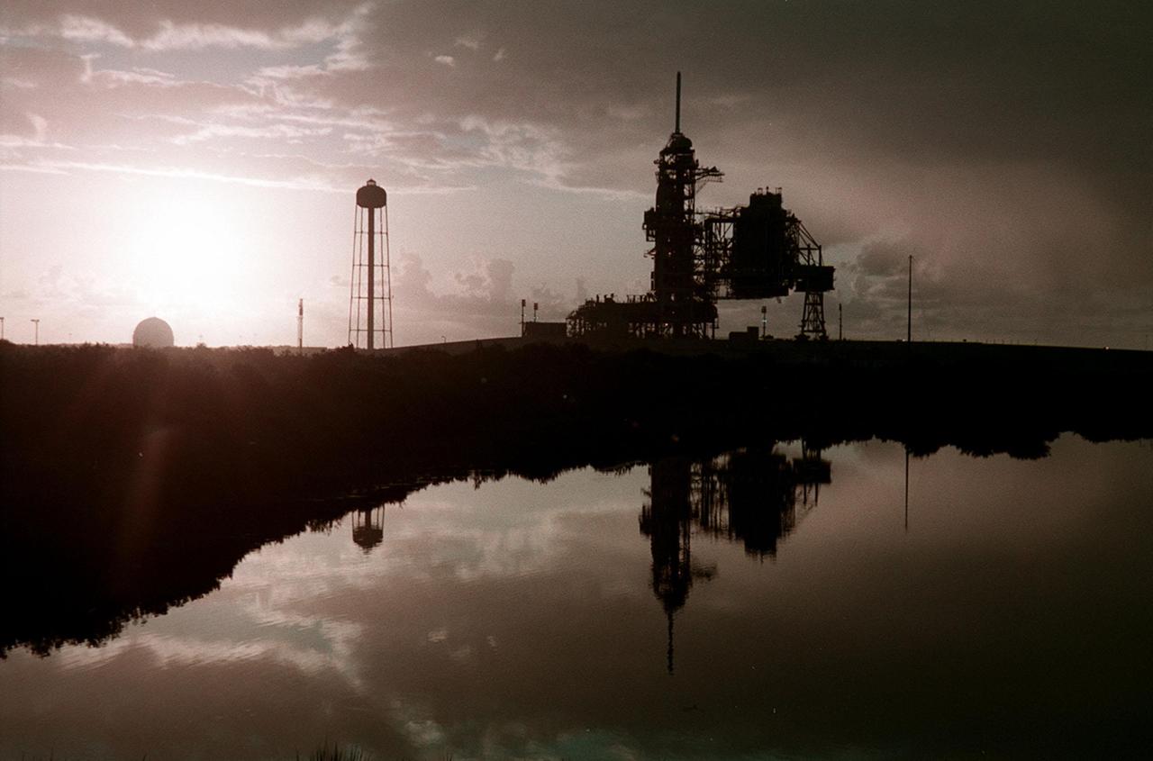
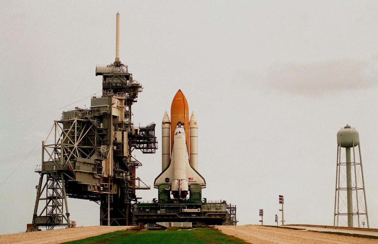
KENNEDY SPACE CENTER, Fla. -- Just after dawn, Launch Pad 39A is caught in silhouette and reflected in the water nearby. On the pad is Space Shuttle Discovery, waiting for launch on mission STS-92 Oct. 5, 2000. At the left of the pad is the 300,000-gallon water tank that is part of the sound suppression system during launches. At far left, the ball-shaped structure is a storage tank for one of the cryogenic liquid propellants of the orbiter’s main engines
An isopropyl alcohol (IPA) tank is lifted into place at the A-3 Test Stand being built at NASA's John C. Stennis Space Center. Fourteen IPA, water and liquid oxygen (LOX) tanks are being installed to support the chemical steam generators to be used on the A-3 Test Stand. The IPA and LOX tanks will provide fuel for the generators. The water will allow the generators to produce steam that will be used to reduce pressure inside the stand's test cell diffuser, enabling operators to simulate altitudes up to 100,000 feet. In that way, operators can perform the tests needed on rocket engines being built to carry humans back to the moon and possibly beyond. The A-3 Test Stand is set for completion and activation in 2011.

A liquid oxygen (LOX) tank is lifted into place at the A-3 Test Stand being built at NASA's John C. Stennis Space Center. Fourteen LOX, isopropyl alcohol (IPA) and water tanks are being installed to support the chemical steam generators to be used on the A-3 Test Stand. The IPA and LOX tanks will provide fuel for the generators. The water will allow the generators to produce steam that will be used to reduce pressure inside the stand's test cell diffuser, enabling operators to simulate altitudes up to 100,000 feet. In that way, operators can perform the tests needed on rocket engines being built to carry humans back to the moon and possibly beyond. The A-3 Test Stand is set for completion and activation in 2011.
A liquid oxygen (LOX) tank is lifted into place at the A-3 Test Stand being built at NASA's John C. Stennis Space Center. Fourteen LOX, isopropyl alcohol (IPA) and water tanks are being installed to support the chemical steam generators to be used on the A-3 Test Stand. The IPA and LOX tanks will provide fuel for the generators. The water will allow the generators to produce steam that will be used to reduce pressure inside the stand's test cell diffuser, enabling operators to simulate altitudes up to 100,000 feet. In that way, operators can perform the tests needed on rocket engines being built to carry humans back to the moon and possibly beyond. The A-3 Test Stand is set for completion and activation in 2011.
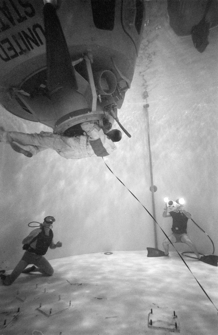
S70-24016 (17 Jan. 1970) --- Astronaut Thomas K. Mattingly II, command module pilot of the Apollo 13 lunar landing mission, participates in water egress training in a water tank in Building 260 at the Manned Spacecraft Center.
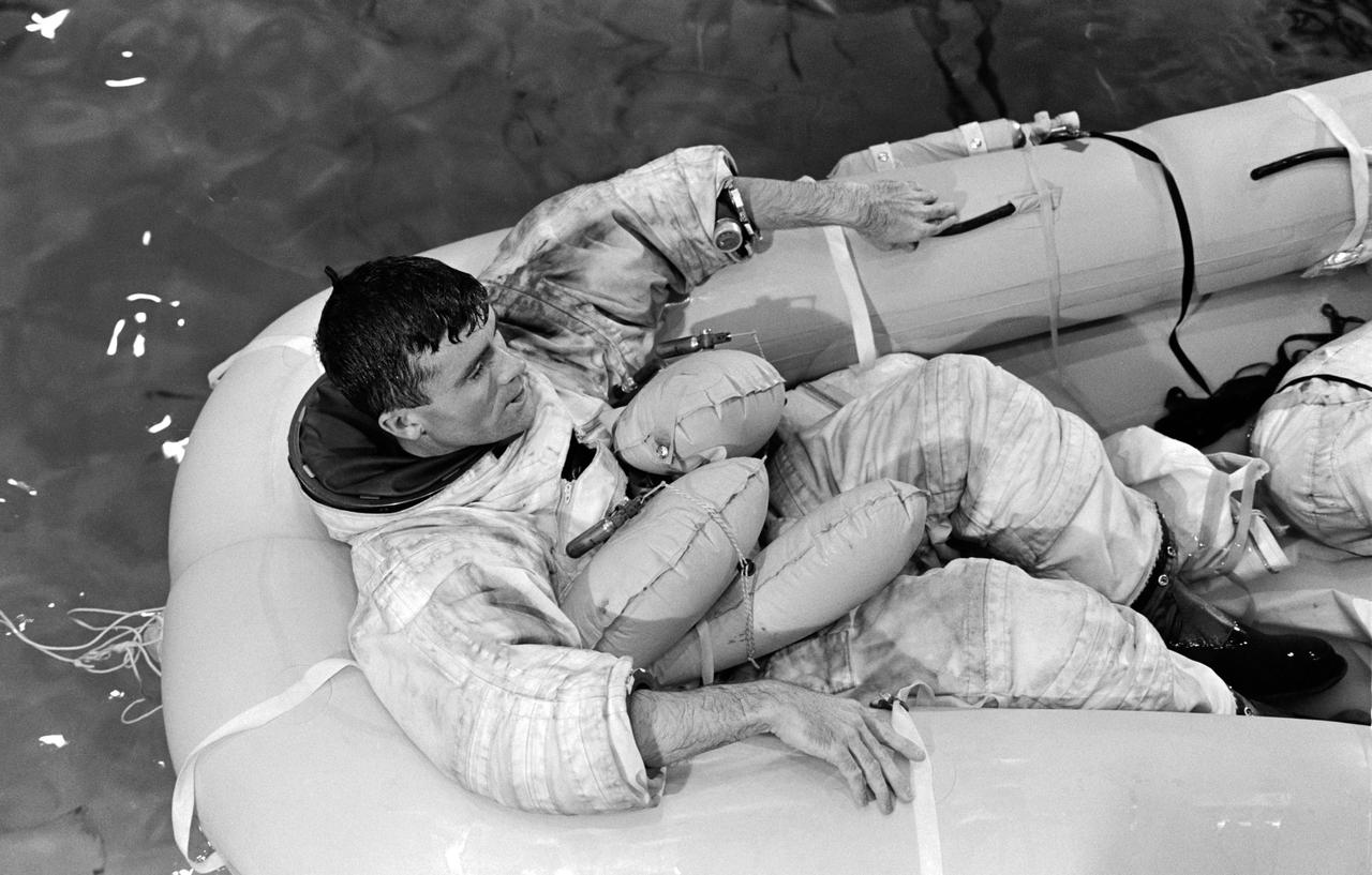
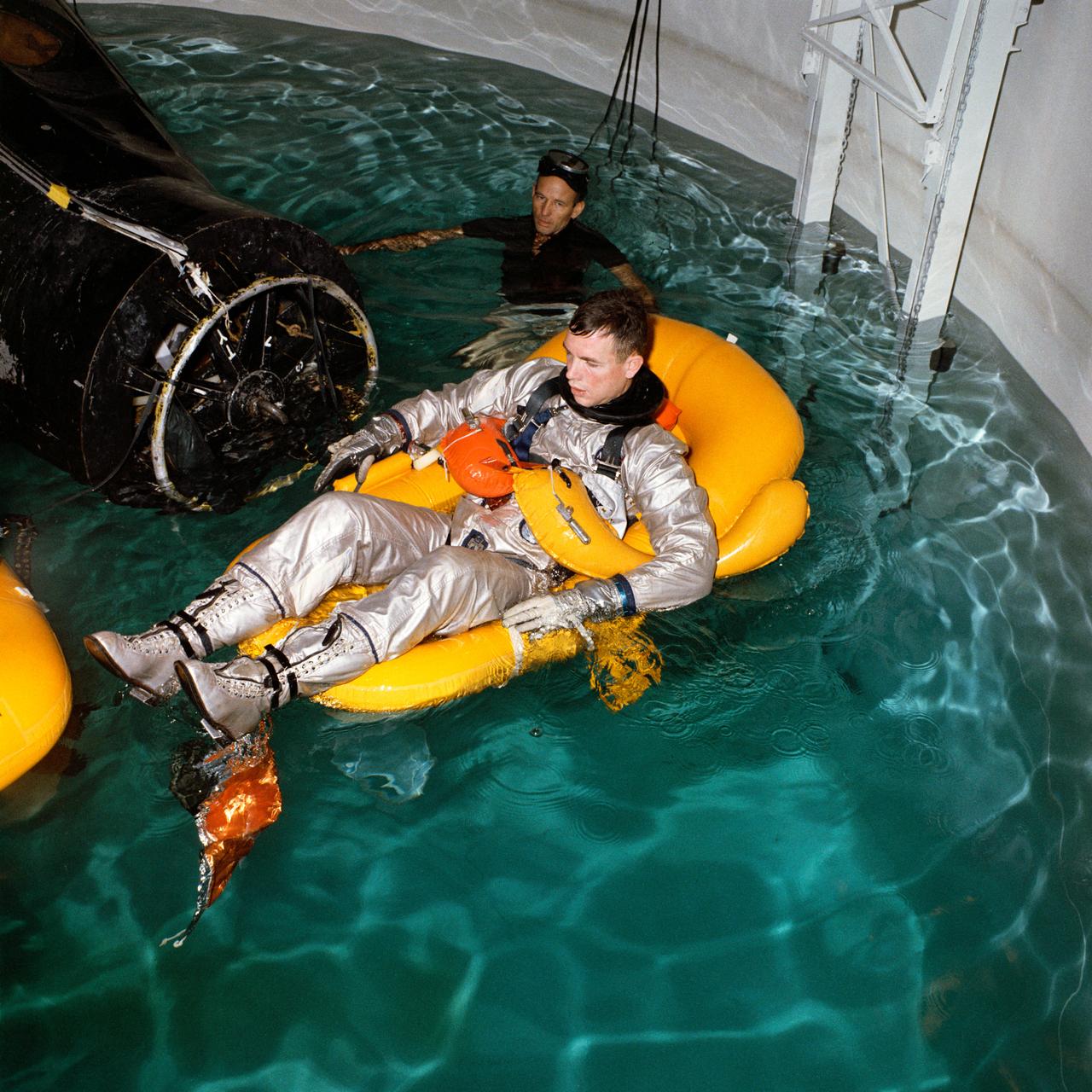
S70-31143 (17 Jan. 1970) --- Astronaut Fred W. Haise Jr., lunar module pilot of the Apollo 13 lunar landing mission, participates in water egress training in a water tank in Building 260 at the Manned Spacecraft Center.
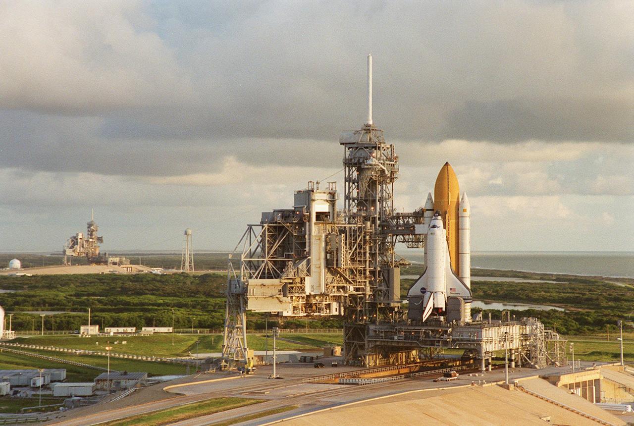
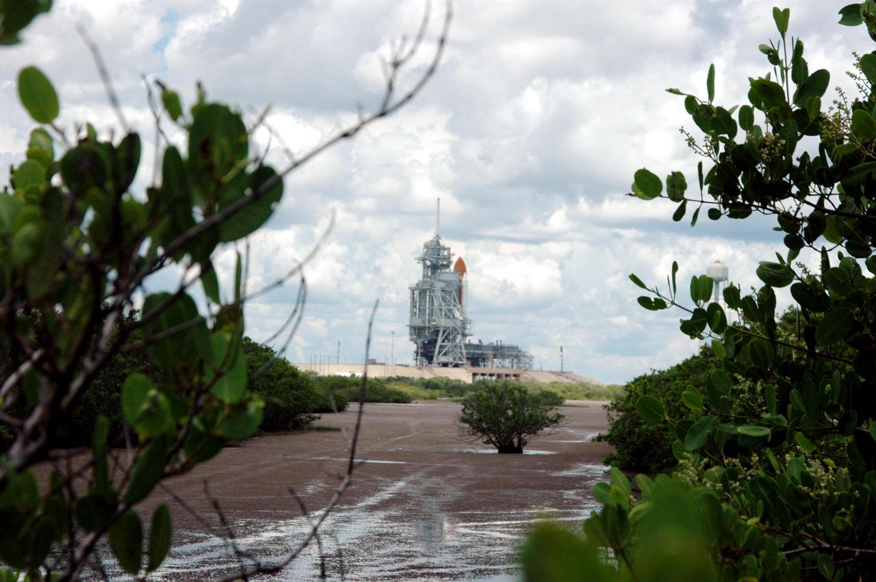
Cloudy skies form a backdrop for Launch Pads 39B (left) and 39A (foreground). Space Shuttle Discovery waits on top of the pad for its launch Oct. 5 to the International Space Station. Between the pads can be seen the 300,000-gallon water tank that provides water for the sound suppression system during launch.

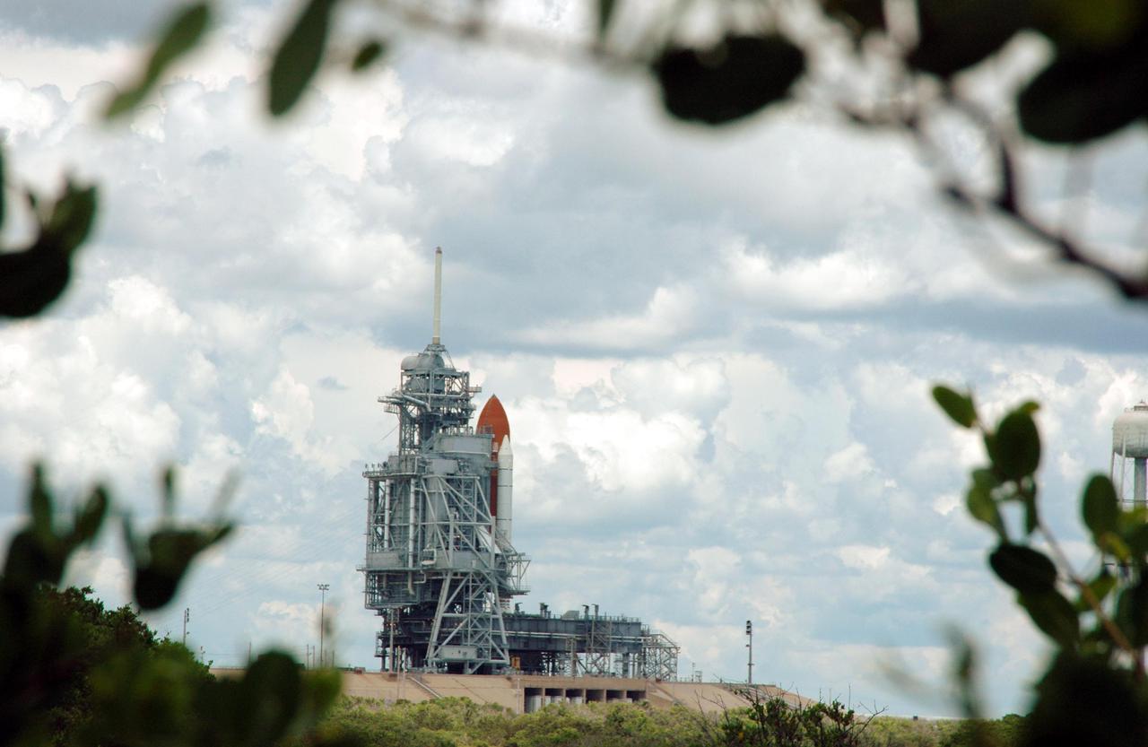
While early morning light spotlights Space Shuttle Discovery on Launch Pad 39A, storm clouds roll in from the east. Launch Pad 39B can be seen in the distance. At right is the 300,000-gallon water tank that provides the water for sound suppression during launch.
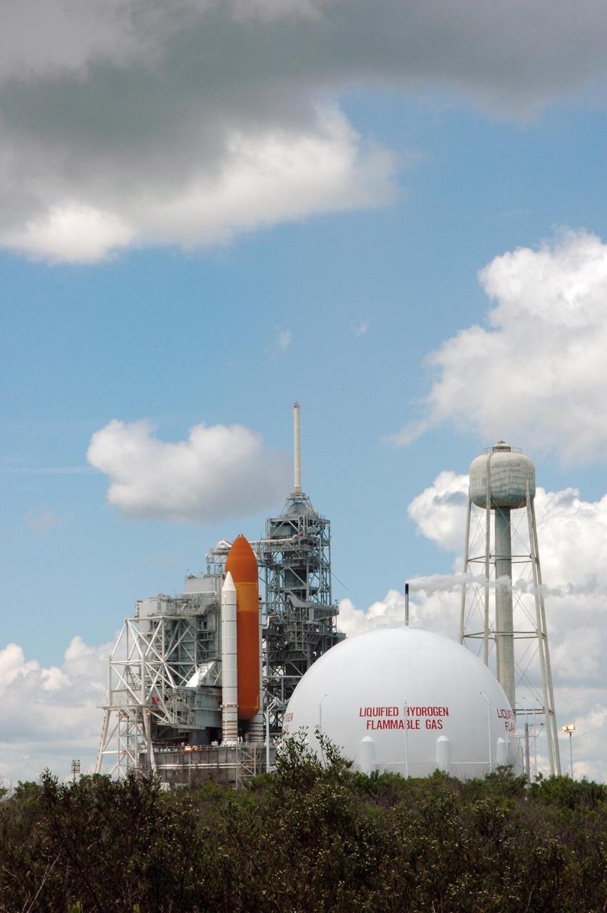
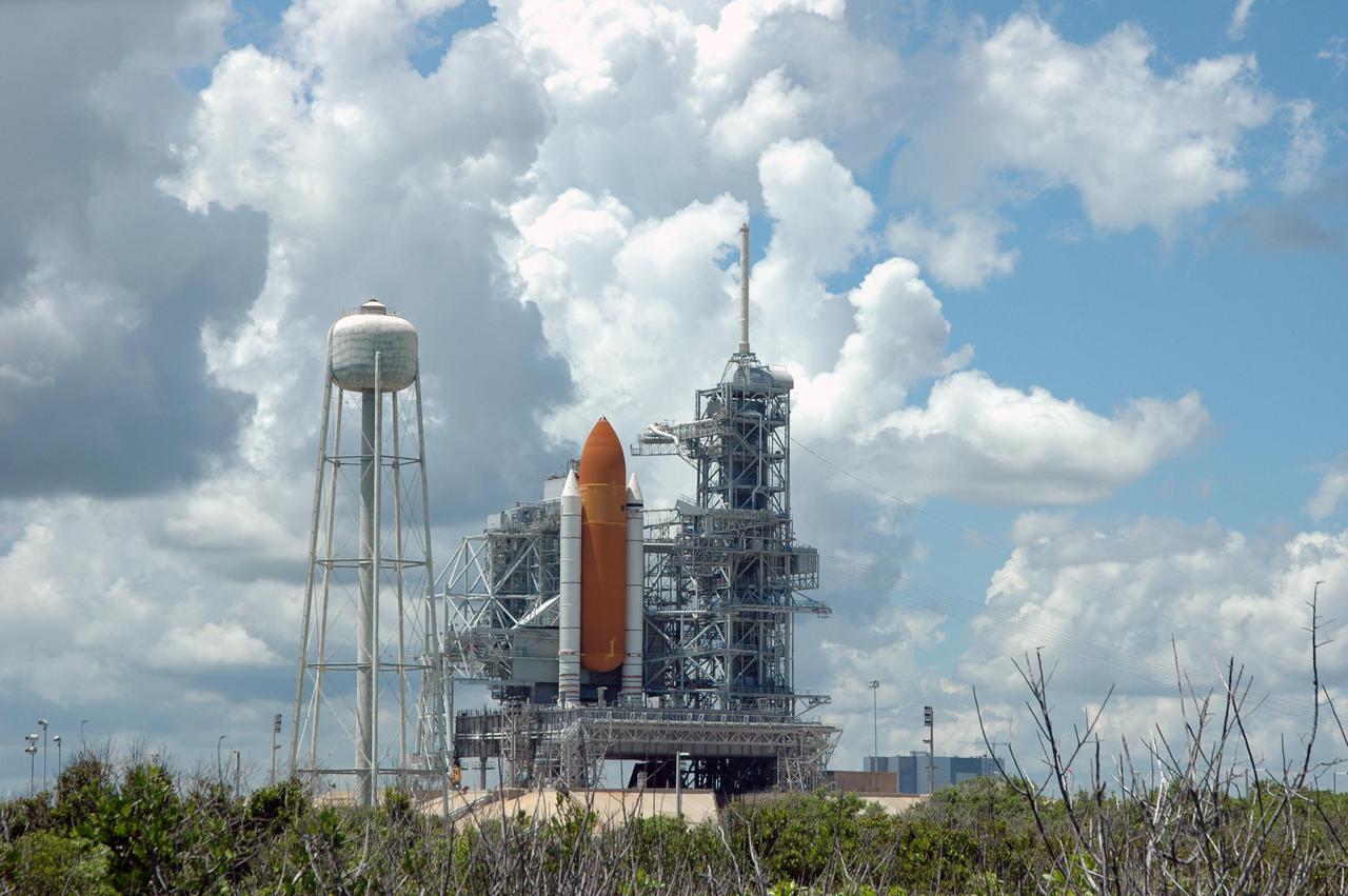
KENNEDY SPACE CENTER, FLA. - Space Shuttle Discovery remains on the pad the day after the Shuttle’s launch on Return to Flight mission STS-114 was scrubbed. In the foreground is the liquid hydrogen storage tank. At right is the 290-foot-tall water tower that holds 300,000 gallons of water, part of the sound suppression system during a launch. The July 13 mission was scrubbed when a low-level fuel cut-off sensor for the liquid hydrogen tank inside the External Tank failed a routine prelaunch check during the countdown July 13, causing mission managers to scrub Discovery's first launch attempt. The sensor protects the Shuttle's main engines by triggering their shutdown in the event fuel runs unexpectedly low. The sensor is one of four inside the liquid hydrogen section of the External Tank (ET).
KENNEDY SPACE CENTER, FLA. - Space Shuttle Discovery remains on the pad the day after the Shuttle’s launch on Return to Flight mission STS-114 was scrubbed. In the foreground is the liquid hydrogen storage tank. At right is the 290-foot-tall water tower that holds 300,000 gallons of water, part of the sound suppression system during a launch. The July 13 mission was scrubbed when a low-level fuel cut-off sensor for the liquid hydrogen tank inside the External Tank failed a routine prelaunch check during the countdown July 13, causing mission managers to scrub Discovery's first launch attempt. The sensor protects the Shuttle's main engines by triggering their shutdown in the event fuel runs unexpectedly low. The sensor is one of four inside the liquid hydrogen section of the External Tank (ET).
KENNEDY SPACE CENTER, FLA. - Space Shuttle Discovery remains on the pad the day after the Shuttle’s launch on Return to Flight mission STS-114 was scrubbed. In the foreground is the liquid hydrogen storage tank. At right is the 290-foot-tall water tower that holds 300,000 gallons of water, part of the sound suppression system during a launch. The July 13 mission was scrubbed when a low-level fuel cut-off sensor for the liquid hydrogen tank inside the External Tank failed a routine prelaunch check during the countdown July 13, causing mission managers to scrub Discovery's first launch attempt. The sensor protects the Shuttle's main engines by triggering their shutdown in the event fuel runs unexpectedly low. The sensor is one of four inside the liquid hydrogen section of the External Tank (ET).
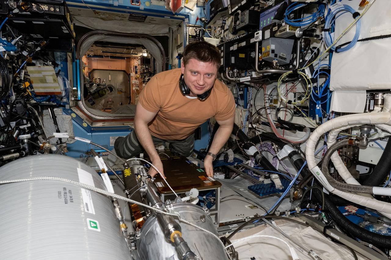
iss071e523250 (Aug. 21, 2024) --- Roscosmos cosmonaut and Expedition 71 Flight Engineer Alexander Grebenkin works on transferring water from resupply tanks to life support systems aboard the International Space Station's Destiny laboratory module
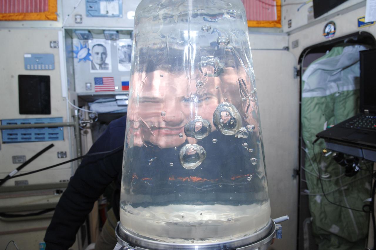
ISS034-E-010446 (31 Dec. 2012) --- Russian cosmonaut Roman Romanenko, Expedition 34 flight engineer, looks through a Rodnik tank in the Zvezda Service Module of the International Space Station. Romanenko performed a water transfer from a Rodnik tank in the Progress to a Rodnik tank in the Zvezda Service Module. Note the multiple refractions of the cosmonaut?s head and shoulders in the bubbles.
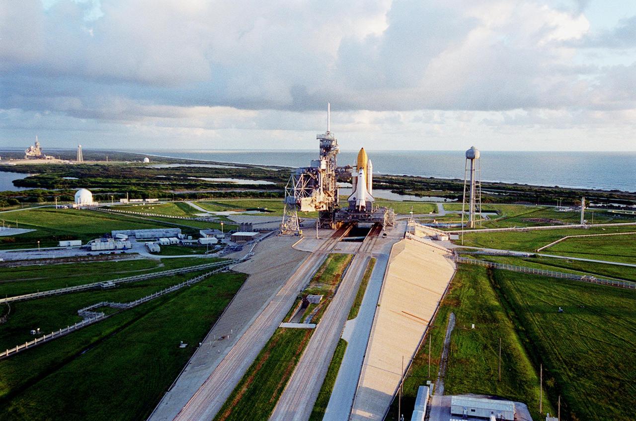
KENNEDY SPACE CENTER, Fla. -- The early morning sun falls on Launch Pad 39A and Space Shuttle Discovery, which is waiting for launch on mission STS-92 Oct. 5, 2000. Leading to the pad (from the foreground) is the ramp leading from the crawlerway, the specially built road that provides the Shuttles access to the pads from the Vehicle Assembly Building. At the right of the pad is the 300,000-gallon water tank that is part of the sound suppression system during launches. Beyond is the Atlantic Ocean. At the far left can be seen Launch Pad 39B with its water tank

KENNEDY SPACE CENTER, Fla. -- The early morning sun falls on Launch Pad 39A and Space Shuttle Discovery, which is waiting for launch on mission STS-92 Oct. 5, 2000. Leading to the pad (from the foreground) is the ramp leading from the crawlerway, the specially built road that provides the Shuttles access to the pads from the Vehicle Assembly Building. At the right of the pad is the 300,000-gallon water tank that is part of the sound suppression system during launches. Beyond is the Atlantic Ocean. At the far left can be seen Launch Pad 39B with its water tank

KENNEDY SPACE CENTER, FLA. -- Calm waters in the Launch Complex 39 Area turn basin provide smooth transit for the Pegasus barge, carrying external tank No. 120. The tank will be used for launching Space Shuttle Discovery on mission STS-120 in October. The barge has carried the tank from the Michoud Assembly Facility near New Orleans, making the journey around the Florida peninsula in tow by the JA Bisso II tugboat, to Port Canaveral and Kennedy Space Center. After the tank is offloaded, it will be towed to the Vehicle Assembly Building for lifting into a checkout cell. NASA/Amanda Diller
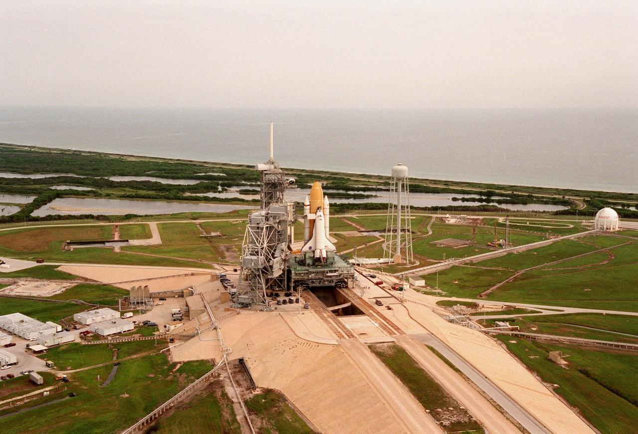
The STS-95 Space Shuttle Discovery sits on the Mobile Launch Platform, still atop the crawler transporter, at Launch Pad 39B. To its left is the Fixed Service Structure that provides access to the orbiter and the Rotating Service Structure. To its right is the elevated water tank, with a capacity of 300,000 gallons. Part of the sound suppression water system, the tank stands 290 feet high on the northeast side of the pad. Water from the tank is released just before ignition of the orbiter's three main engines and twin solid rocket boosters. The entire system reduces the acoustical levels within the orbiter's payload bay to an acceptable 142 decibels. Beyond the orbiter is seen the Atlantic Ocean. While at the launch pad, the orbiter, external tank and solid rocket boosters will undergo final preparations for the launch, scheduled to lift off Oct. 29. The mission includes research payloads such as the Spartan solar-observing deployable spacecraft, the Hubble Space Telescope Orbital Systems Test Platform, the International Extreme Ultraviolet Hitchhiker, as well as the SPACEHAB single module with experiments on space flight and the aging process
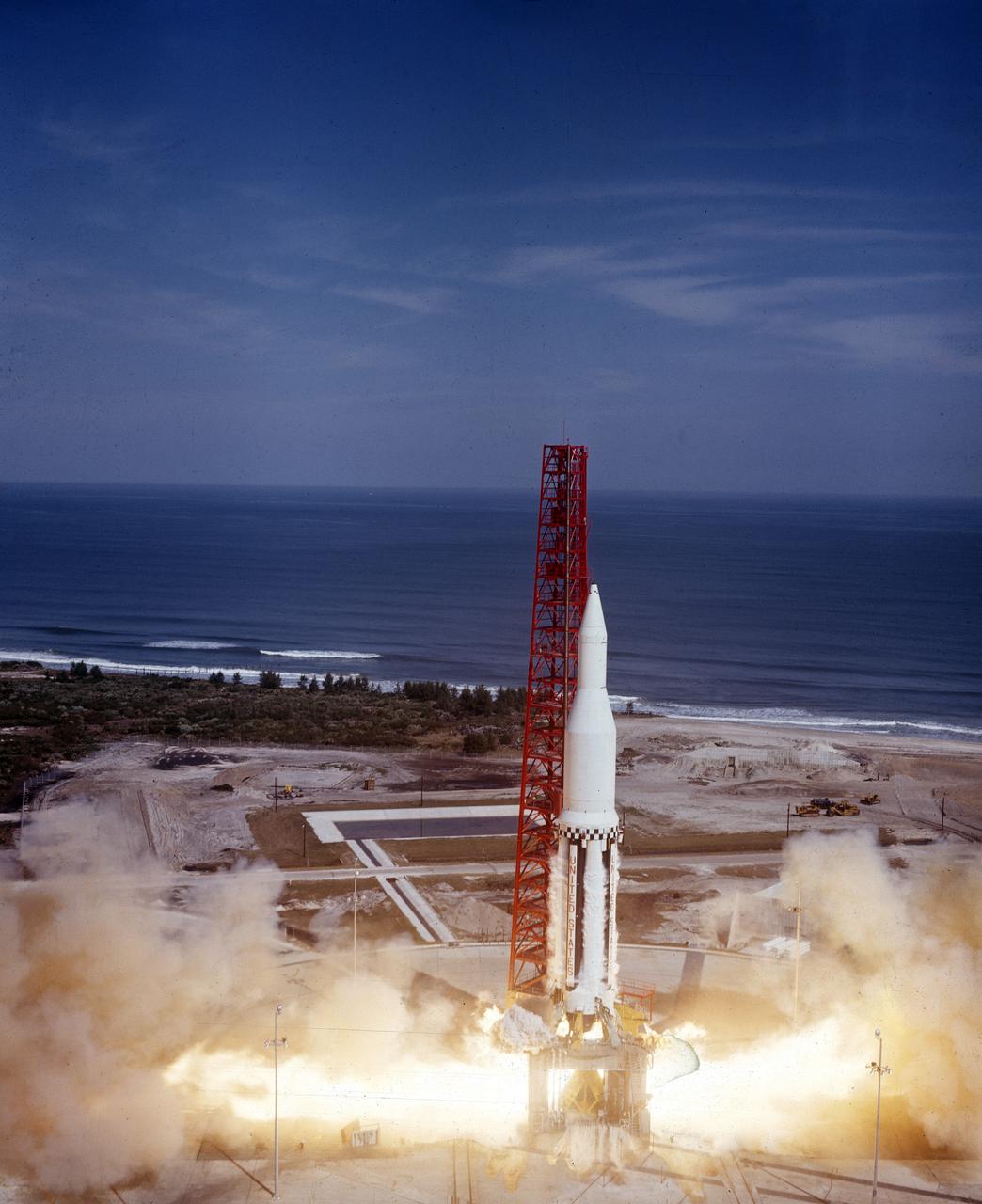
The Saturn I (SA-3) flight lifted off from Kennedy Space Center launch Complex 34, November 16, 1962. The third launch of Saturn launch vehicles, developed at the Marshall Space Flight Center (MSFC) under the direction of Dr. Wernher von Braun, incorporated a Saturn I, Block I engine. The typical height of a Block I vehicle was approximately 163 feet. and had only one live stage. It consisted of eight tanks, each 70 inches in diameter, clustered around a central tank, 105 inches in diameter. Four of the external tanks were fuel tanks for the RP-1 (kerosene) fuel. The other four, spaced alternately with the fuel tanks, were liquid oxygen tanks as was the large center tank. All fuel tanks and liquid oxygen tanks drained at the same rates respectively. The thrust for the stage came from eight H-1 engines, each producing a thrust of 165,000 pounds, for a total thrust of over 1,300,000 pounds. The engines were arranged in a double pattern. Four engines, located inboard, were fixed in a square pattern around the stage axis and canted outward slightly, while the remaining four engines were located outboard in a larger square pattern offset 40 degrees from the inner pattern. Unlike the inner engines, each outer engine was gimbaled. That is, each could be swung through an arc. They were gimbaled as a means of steering the rocket, by letting the instrumentation of the rocket correct any deviations of its powered trajectory. The block I required engine gimabling as the only method of guiding and stabilizing the rocket through the lower atmosphere. The upper stages of the Block I rocket reflected the three-stage configuration of the Saturn I vehicle. During the SA-3 flight, the upper stage ejected 113,560 liters (30,000 gallons) of ballast water in the upper atmosphere for "Project Highwater" physics experiment. The water was released at an altitude of 65 miles, where within only 5 seconds, it expanded into a massive ice cloud 4.6 miles in diameter. Release of this vast quantity of water in a near-space environment marked the first purely scientific large-scale experiment.
KENNEDY SPACE CENTER, FLA. - Space Shuttle Discovery remains on the pad the day after the Shuttle’s launch on Return to Flight mission STS-114 was scrubbed. The Rotating Service Structure has been closed. At left is the 290-foot-tall water tower that holds 300,000 gallons of water, part of the sound suppression system during a launch. The July 13 mission was scrubbed when a low-level fuel cut-off sensor for the liquid hydrogen tank inside the External Tank failed a routine prelaunch check during the countdown July 13, causing mission managers to scrub Discovery's first launch attempt. The sensor protects the Shuttle's main engines by triggering their shutdown in the event fuel runs unexpectedly low. The sensor is one of four inside the liquid hydrogen section of the External Tank (ET).
KENNEDY SPACE CENTER, FLA. - On Launch Pad 39B, Space Shuttle Discovery is revealed after rollback of the Rotating Service Structure. At right of the pad is the 290-foot-tall water tower that holds 300,000 gallons of water, part of the sound suppression system during a launch. Discovery will be rolled back to the Vehicle Assembly Building. Once inside the VAB, Discovery will be demated from its External Tank and lifted into the transfer aisle. On or about June 7, Discovery will be lifted and attached to its new tank and Solid Rocket Boosters, which are already in the VAB. Only the 15th rollback in Space Shuttle Program history, the 4.2-mile journey allows additional modifications to be made to the External Tank prior to a safe Return to Flight. Discovery is expected to be rolled back to the launch pad in mid-June for Return to Flight mission STS-114. The launch window extends from July 13 to July 31.
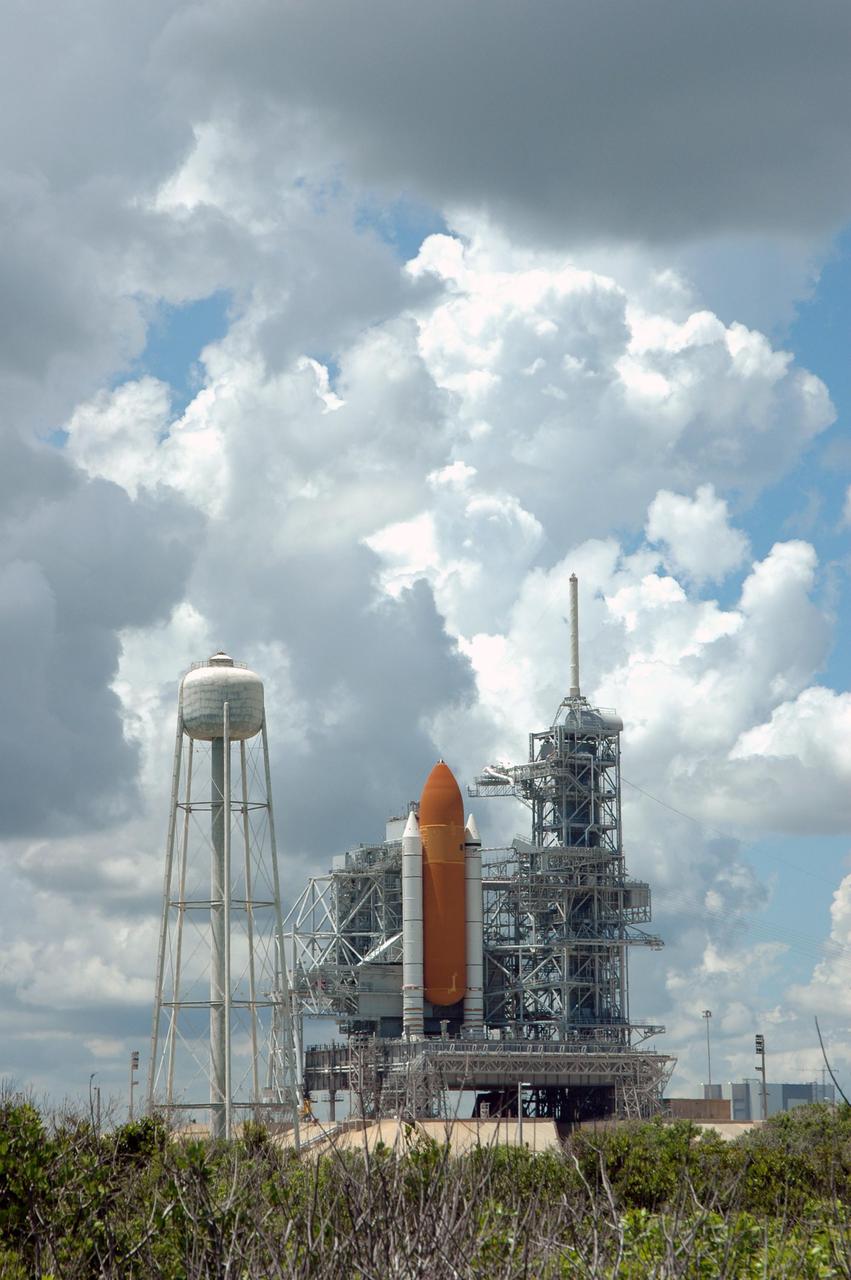
KENNEDY SPACE CENTER, FLA. - Space Shuttle Discovery remains on the pad the day after the Shuttle’s launch on Return to Flight mission STS-114 was scrubbed. The Rotating Service Structure has been closed. At left is the 290-foot-tall water tower that holds 300,000 gallons of water, part of the sound suppression system during a launch. Above the Shuttle at right is the 80-foot lightning mast. The July 13 mission was scrubbed when a low-level fuel cut-off sensor for the liquid hydrogen tank inside the External Tank failed a routine prelaunch check during the countdown July 13, causing mission managers to scrub Discovery's first launch attempt. The sensor protects the Shuttle's main engines by triggering their shutdown in the event fuel runs unexpectedly low. The sensor is one of four inside the liquid hydrogen section of the External Tank (ET).
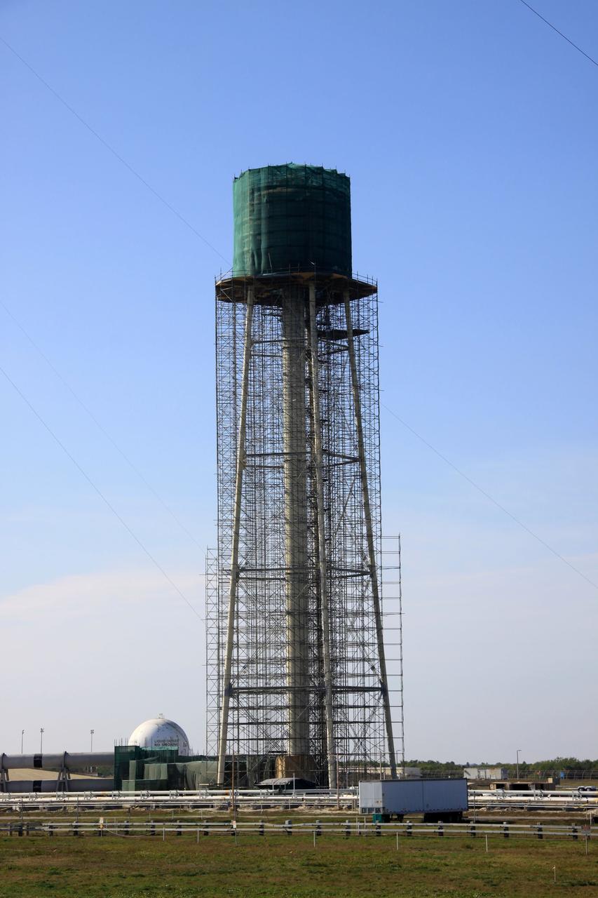
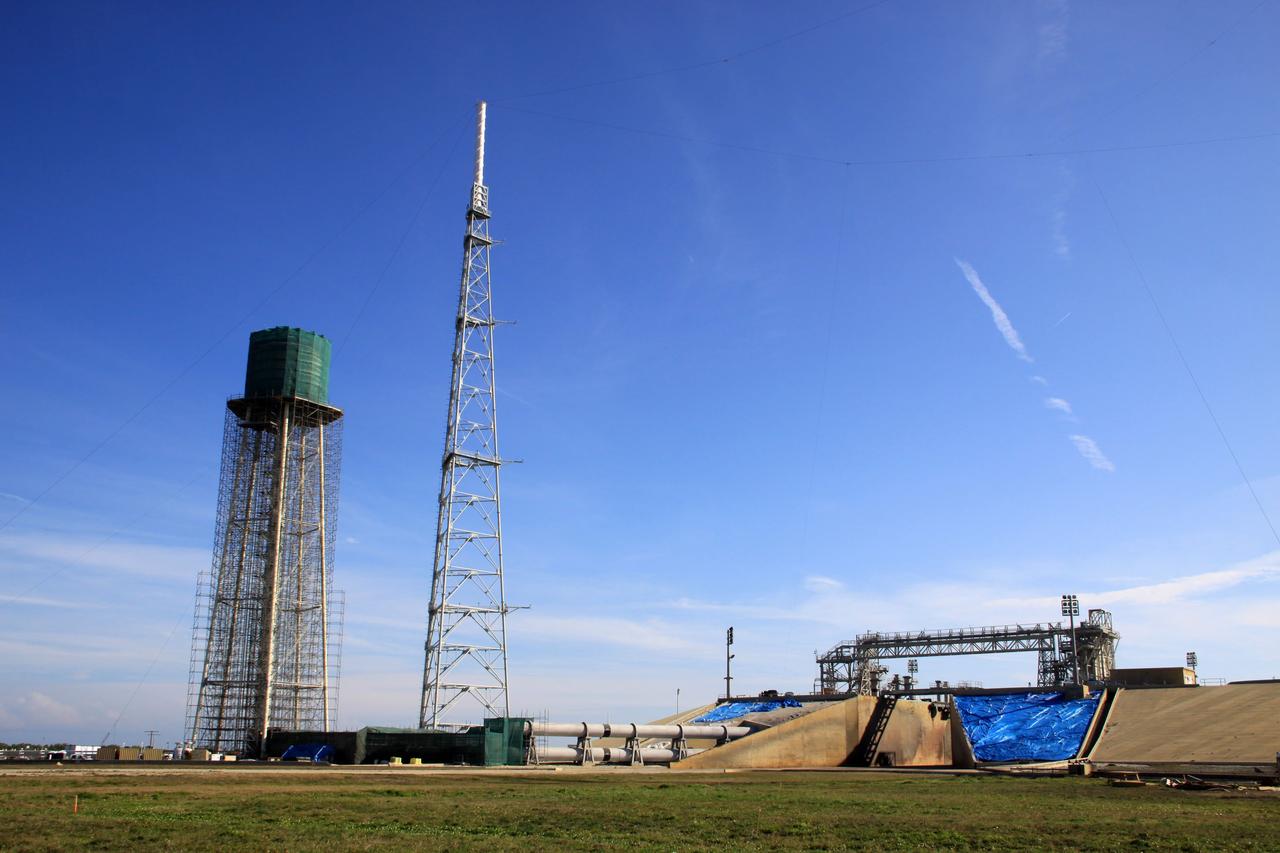
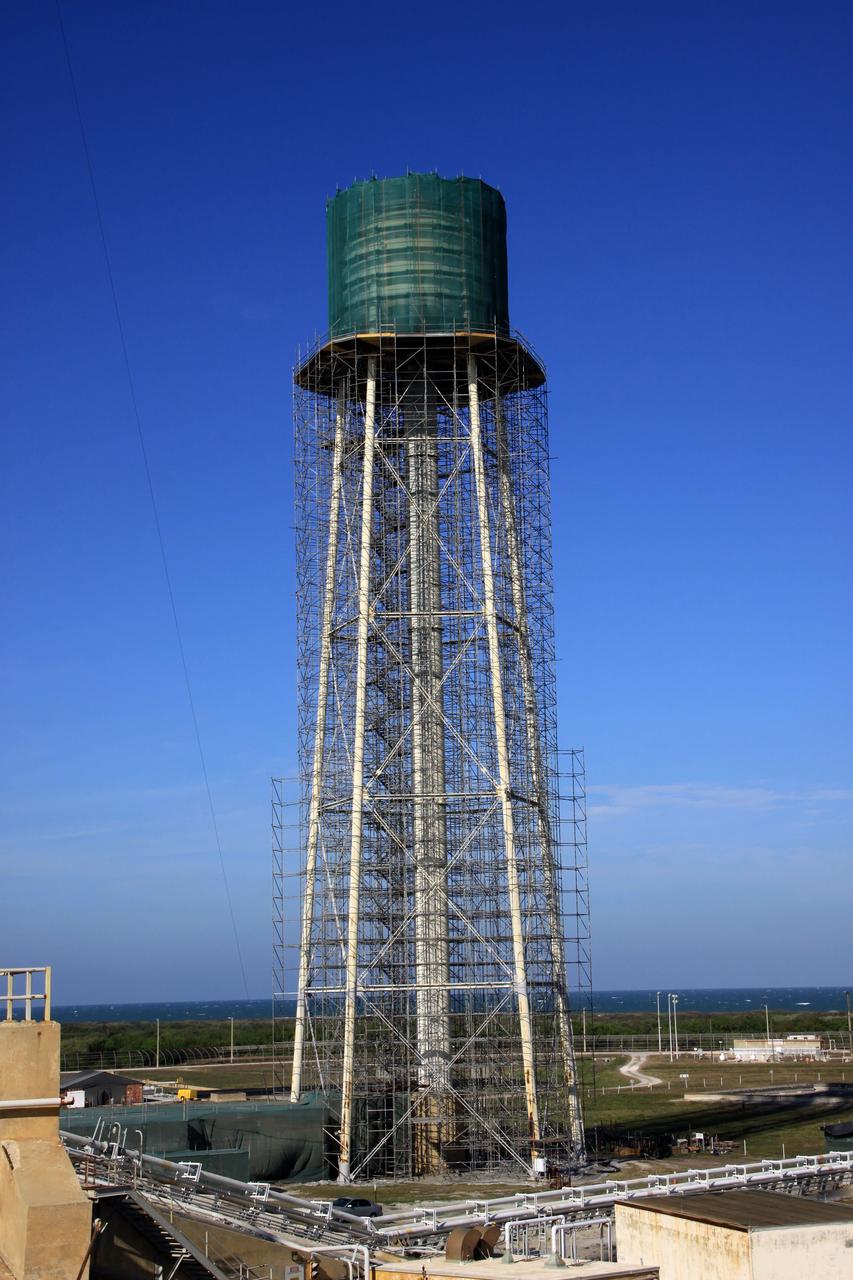
CAPE CANAVERAL, Fla. - At NASA’s Kennedy Space Center in Florida, preparations are underway to sandblast and paint the 290-foot-high water tower at Launch Pad 39B. Scaffolding surrounds the tower and a special covering has been placed around the tank. The water towers at Launch Complex 39, which includes pad A and B, were part of the sound suppression system used during space shuttle launches. Water stored in the 300,000-gallon tank would be released just prior to main engine ignition and flow by gravity to special mobile launcher platform (MLP) outlets. Nine seconds after shuttle liftoff, the peak flow rate was 900,000 gallons per minute and helped to protect the orbiter and payloads from being damaged by acoustical energy reflected from the MLP during liftoff. Photo Credit: NASA/Jim Grossmann
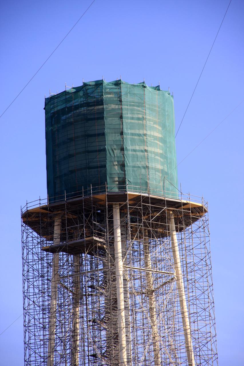
CAPE CANAVERAL, Fla. - At NASA’s Kennedy Space Center in Florida, preparations are underway to sandblast and paint the 290-foot-high water tower at Launch Pad 39B. Scaffolding surrounds the tower and a special covering has been placed around the tank. The water towers at Launch Complex 39, which includes pad A and B, were part of the sound suppression system used during space shuttle launches. Water stored in the 300,000-gallon tank would be released just prior to main engine ignition and flow by gravity to special mobile launcher platform (MLP) outlets. Nine seconds after shuttle liftoff, the peak flow rate was 900,000 gallons per minute and helped to protect the orbiter and payloads from being damaged by acoustical energy reflected from the MLP during liftoff. Photo Credit: NASA/Jim Grossmann
CAPE CANAVERAL, Fla. - At NASA’s Kennedy Space Center in Florida, preparations are underway to sandblast and paint the 290-foot-high water tower at Launch Pad 39B. Scaffolding surrounds the tower and a special covering has been placed around the tank. The water towers at Launch Complex 39, which includes pad A and B, were part of the sound suppression system used during space shuttle launches. Water stored in the 300,000-gallon tank would be released just prior to main engine ignition and flow by gravity to special mobile launcher platform (MLP) outlets. Nine seconds after shuttle liftoff, the peak flow rate was 900,000 gallons per minute and helped to protect the orbiter and payloads from being damaged by acoustical energy reflected from the MLP during liftoff. Photo Credit: NASA/Jim Grossmann
CAPE CANAVERAL, Fla. - At NASA’s Kennedy Space Center in Florida, preparations are underway to sandblast and paint the 290-foot-high water tower at Launch Pad 39B. Scaffolding surrounds the tower and a special covering has been placed around the tank. The water towers at Launch Complex 39, which includes pad A and B, were part of the sound suppression system used during space shuttle launches. Water stored in the 300,000-gallon tank would be released just prior to main engine ignition and flow by gravity to special mobile launcher platform (MLP) outlets. Nine seconds after shuttle liftoff, the peak flow rate was 900,000 gallons per minute and helped to protect the orbiter and payloads from being damaged by acoustical energy reflected from the MLP during liftoff. Photo Credit: NASA/Jim Grossmann
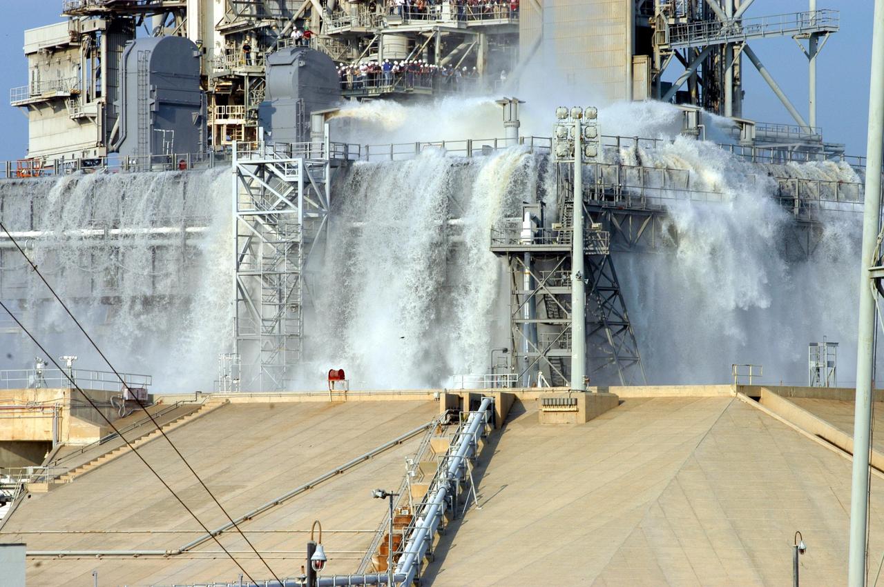
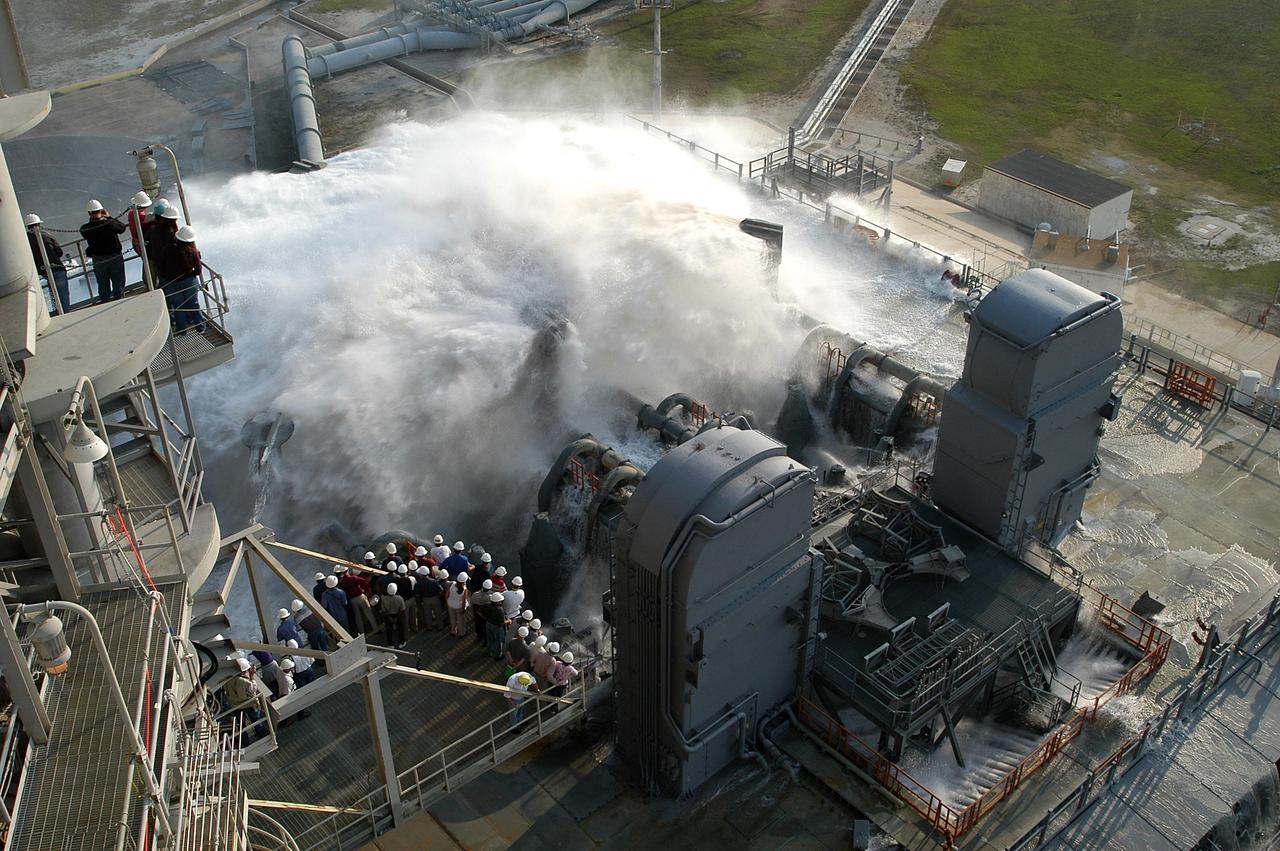
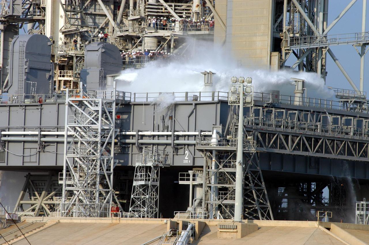
KENNEDY SPACE CENTER, FLA. -- For the fourth time in Space Shuttle Program history, 350,000 gallons of water are released on a Mobile Launcher Platform (MLP) at Launch Pad 39A during a water sound suppression test. This test is being conducted following the replacement of the six main system valves, which had been in place since the beginning of the Shuttle Program and had reached the end of their service life. Also, the hydraulic portion of the valve actuators has been redesigned and simplified to reduce maintenance costs. The sound suppression water system is installed on the launch pads to protect the orbiter and its payloads from damage by acoustical energy reflected from the MLP during launch. The system includes an elevated water tank with a capacity of 300,000 gallons. The tank is 290 feet high and stands on the northeast side of the Pad. The water is released just before the ignition of the orbiter's three main engines and twin solid rocket boosters, and flows through parallel 7-foot-diameter pipes to the Pad area.
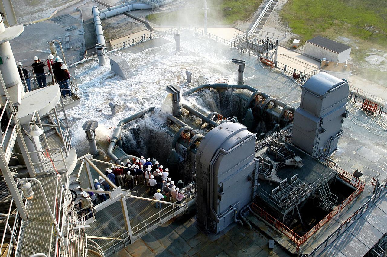
KENNEDY SPACE CENTER, FLA. -- Water recedes from the Mobile Launcher Platform (MLP) on Launch Pad 39A after the water sound suppression test. Workers and the media (left) were on hand to witness the rare event. This test was conducted following the replacement of the six main system valves, which had been in place since the beginning of the Shuttle Program and had reached the end of their service life. Also, the hydraulic portion of the valve actuators has been redesigned and simplified to reduce maintenance costs. The sound suppression water system is installed on the launch pads to protect the orbiter and its payloads from damage by acoustical energy reflected from the MLP during launch. The system includes an elevated water tank with a capacity of 300,000 gallons. The tank is 290 feet high and stands on the northeast side of the Pad. The water is released just before the ignition of the orbiter's three main engines and twin solid rocket boosters, and flows through parallel 7-foot-diameter pipes to the Pad area.
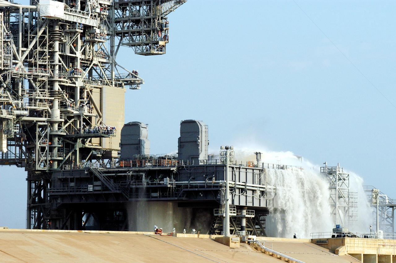
KENNEDY SPACE CENTER, FLA. -- For the fourth time in Space Shuttle Program history, 350,000 gallons of water are being released on a Mobile Launcher Platform (MLP) at Launch Pad 39A during a water sound suppression test. Because of the unusual event, media and workers watch from nearby vantage points on the Fixed Service Structure (left). This test is being conducted following the replacement of the six main system valves, which had been in place since the beginning of the Shuttle Program and had reached the end of their service life. Also, the hydraulic portion of the valve actuators has been redesigned and simplified to reduce maintenance costs. The sound suppression water system is installed on the launch pads to protect the orbiter and its payloads from damage by acoustical energy reflected from the MLP during launch. The system includes an elevated water tank with a capacity of 300,000 gallons. The tank is 290 feet high and stands on the northeast side of the Pad. The water is released just before the ignition of the orbiter's three main engines and twin solid rocket boosters, and flows through parallel 7-foot-diameter pipes to the Pad area.
KENNEDY SPACE CENTER, FLA. -- For the fourth time in Space Shuttle Program history, 350,000 gallons of water are being released on a Mobile Launcher Platform (MLP) at Launch Pad 39A during a water sound suppression test. Because of the unusual event, media and workers watch from nearby vantage points on the Fixed Service Structure (left). This test is being conducted following the replacement of the six main system valves, which had been in place since the beginning of the Shuttle Program and had reached the end of their service life. Also, the hydraulic portion of the valve actuators has been redesigned and simplified to reduce maintenance costs. The sound suppression water system is installed on the launch pads to protect the orbiter and its payloads from damage by acoustical energy reflected from the MLP during launch. The system includes an elevated water tank with a capacity of 300,000 gallons. The tank is 290 feet high and stands on the northeast side of the Pad. The water is released just before the ignition of the orbiter's three main engines and twin solid rocket boosters, and flows through parallel 7-foot-diameter pipes to the Pad area.
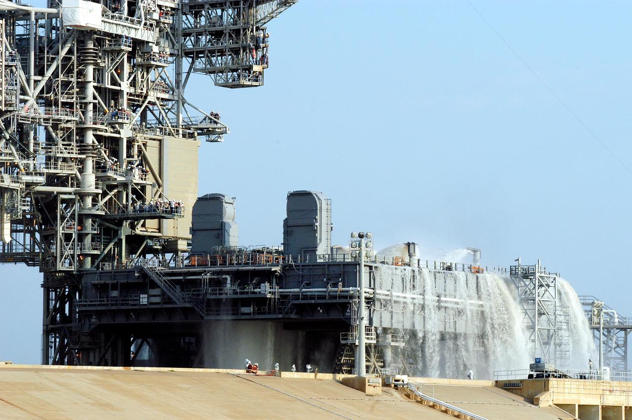
KENNEDY SPACE CENTER, FLA. -- For the fourth time in Space Shuttle Program history, 350,000 gallons of water are released on a Mobile Launcher Platform (MLP) at Launch Pad 39A during a water sound suppression test. This test is being conducted following the replacement of the six main system valves, which had been in place since the beginning of the Shuttle Program and had reached the end of their service life. Also, the hydraulic portion of the valve actuators has been redesigned and simplified to reduce maintenance costs. The sound suppression water system is installed on the launch pads to protect the orbiter and its payloads from damage by acoustical energy reflected from the MLP during launch. The system includes an elevated water tank with a capacity of 300,000 gallons. The tank is 290 feet high and stands on the northeast side of the Pad. The water is released just before the ignition of the orbiter's three main engines and twin solid rocket boosters, and flows through parallel 7-foot-diameter pipes to the Pad area.
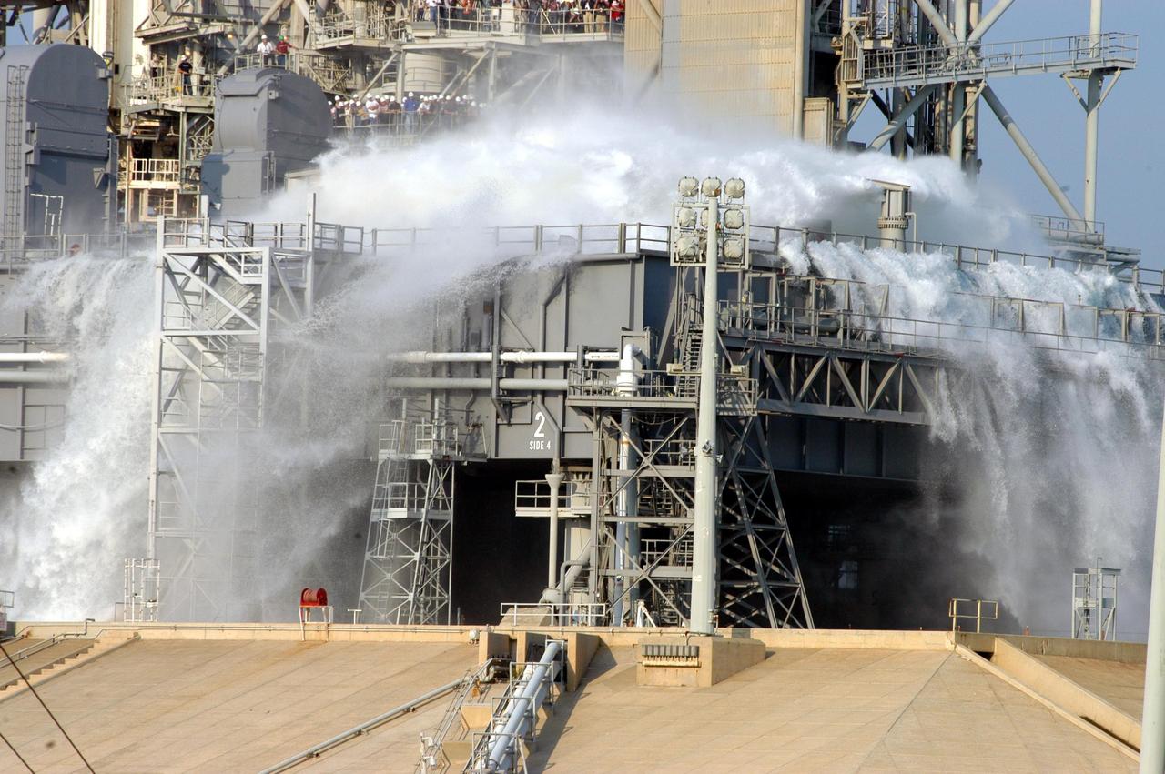
KENNEDY SPACE CENTER, FLA. -- Water is released onto the Mobile Launcher Platform (MLP) on Launch Pad 39A at the start of a water sound suppression test. Workers and the media (left) are on hand to witness the rare event. This test is being conducted following the replacement of the six main system valves, which had been in place since the beginning of the Shuttle Program and had reached the end of their service life. Also, the hydraulic portion of the valve actuators has been redesigned and simplified to reduce maintenance costs. The sound suppression water system is installed on the launch pads to protect the orbiter and its payloads from damage by acoustical energy reflected from the MLP during launch. The system includes an elevated water tank with a capacity of 300,000 gallons. The tank is 290 feet high and stands on the northeast side of the Pad. The water is released just before the ignition of the orbiter's three main engines and twin solid rocket boosters, and flows through parallel 7-foot-diameter pipes to the Pad area.

KENNEDY SPACE CENTER, FLA. -- Water is released onto the Mobile Launcher Platform (MLP) on Launch Pad 39A at the start of a water sound suppression test. Workers and the media (left) are on hand to witness the rare event. This test is being conducted following the replacement of the six main system valves, which had been in place since the beginning of the Shuttle Program and had reached the end of their service life. Also, the hydraulic portion of the valve actuators has been redesigned and simplified to reduce maintenance costs. The sound suppression water system is installed on the launch pads to protect the orbiter and its payloads from damage by acoustical energy reflected from the MLP during launch. The system includes an elevated water tank with a capacity of 300,000 gallons. The tank is 290 feet high and stands on the northeast side of the Pad. The water is released just before the ignition of the orbiter's three main engines and twin solid rocket boosters, and flows through parallel 7-foot-diameter pipes to the Pad area.

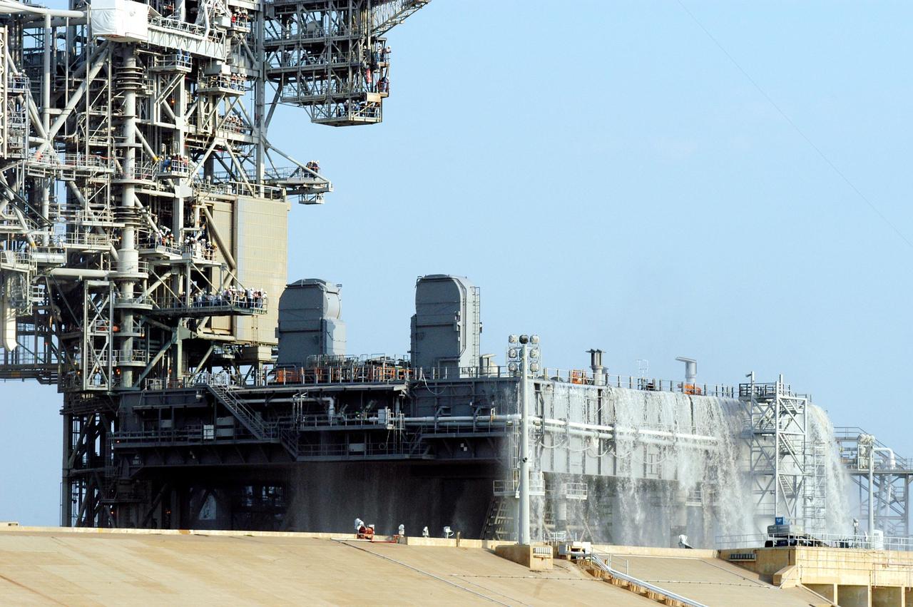
KENNEDY SPACE CENTER, FLA. -- For the fourth time in Space Shuttle Program history, 350,000 gallons of water are released on a Mobile Launcher Platform (MLP) at Launch Pad 39A during a water sound suppression test. Because of the unusual event, media and workers watch from nearby vantage points on the Fixed Service Structure (left). This test is being conducted following the replacement of the six main system valves, which had been in place since the beginning of the Shuttle Program and had reached the end of their service life. Also, the hydraulic portion of the valve actuators has been redesigned and simplified to reduce maintenance costs. The sound suppression water system is installed on the launch pads to protect the orbiter and its payloads from damage by acoustical energy reflected from the MLP during launch. The system includes an elevated water tank with a capacity of 300,000 gallons. The tank is 290 feet high and stands on the northeast side of the Pad. The water is released for launch just before the ignition of the orbiter's three main engines and twin solid rocket boosters, and flows through parallel 7-foot-diameter pipes to the Pad area.
KENNEDY SPACE CENTER, FLA. -- For the fourth time in Space Shuttle Program history, 350,000 gallons of water are being released on a Mobile Launcher Platform (MLP) at Launch Pad 39A during a water sound suppression test. Because of the unusual event, media and workers watch from nearby vantage points on the Fixed Service Structure (left). This test is being conducted following the replacement of the six main system valves, which had been in place since the beginning of the Shuttle Program and had reached the end of their service life. Also, the hydraulic portion of the valve actuators has been redesigned and simplified to reduce maintenance costs. The sound suppression water system is installed on the launch pads to protect the orbiter and its payloads from damage by acoustical energy reflected from the MLP during launch. The system includes an elevated water tank with a capacity of 300,000 gallons. The tank is 290 feet high and stands on the northeast side of the Pad. The water is released just before the ignition of the orbiter's three main engines and twin solid rocket boosters, and flows through parallel 7-foot-diameter pipes to the Pad area.
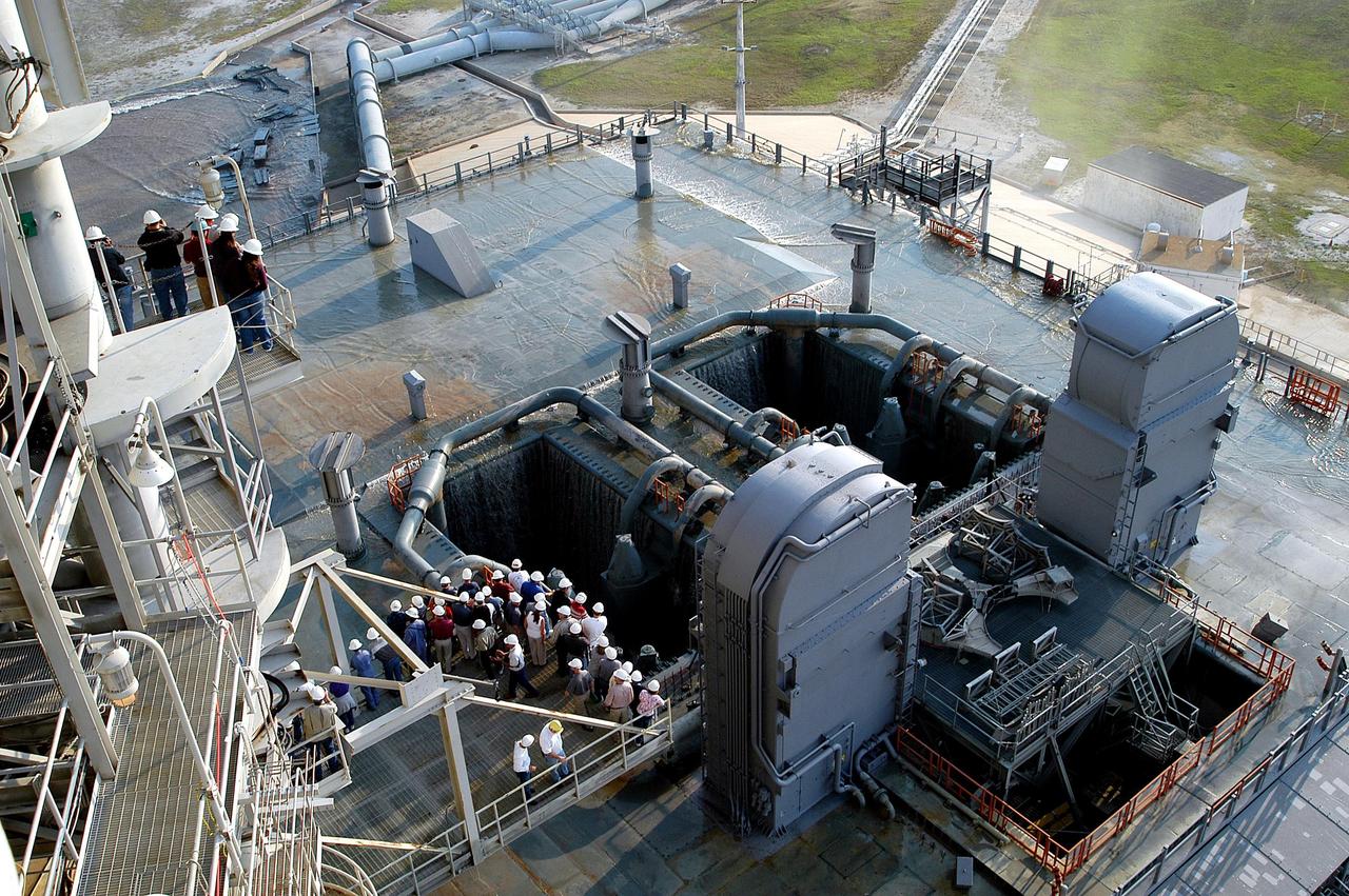
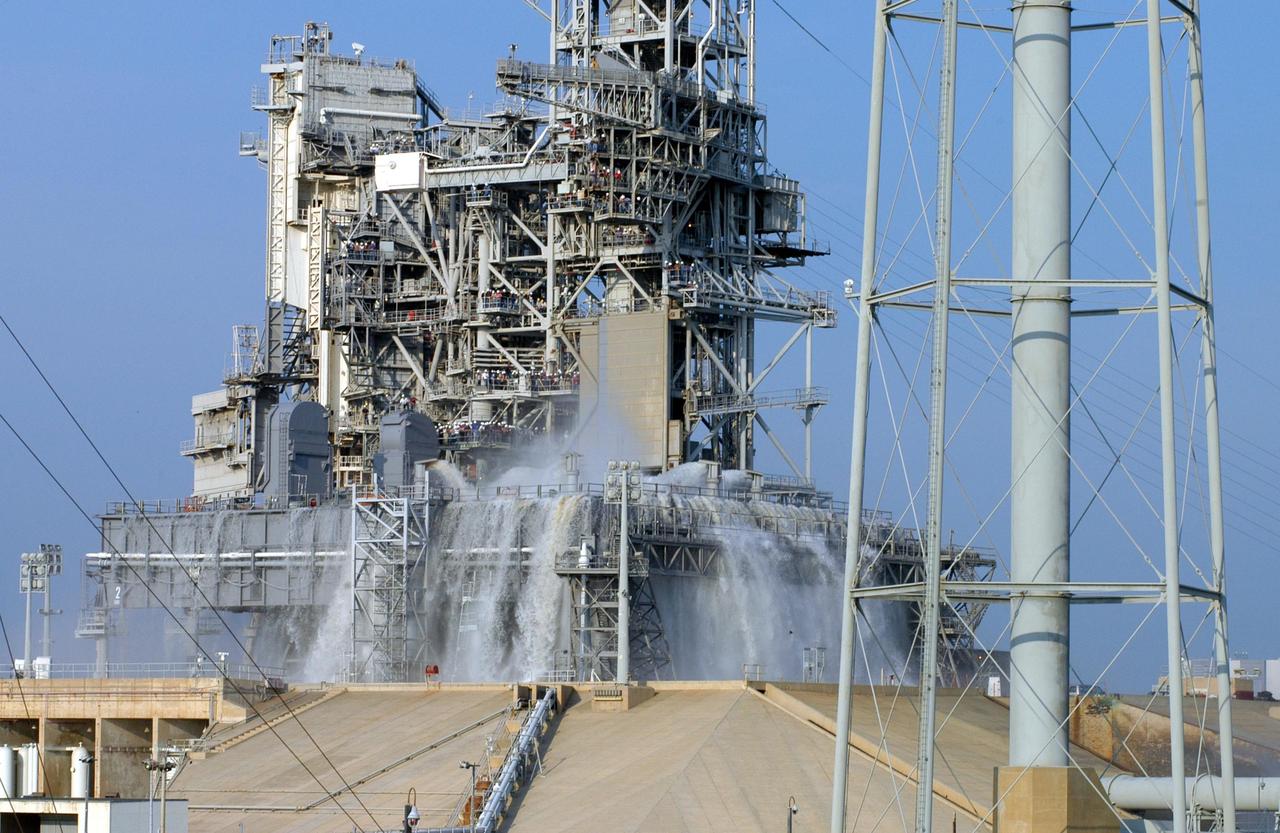
KENNEDY SPACE CENTER, FLA. -- Some water remains on the surface of the Mobile Launcher Platform (MLP) on Launch Pad 39A after a water sound suppression test. Workers and the media (left) were on hand to witness the rare event. This test was conducted following the replacement of the six main system valves, which had been in place since the beginning of the Shuttle Program and had reached the end of their service life. Also, the hydraulic portion of the valve actuators has been redesigned and simplified to reduce maintenance costs. The sound suppression water system is installed on the launch pads to protect the orbiter and its payloads from damage by acoustical energy reflected from the MLP during launch. The system includes an elevated water tank with a capacity of 300,000 gallons. The tank is 290 feet high and stands on the northeast side of the Pad. The water is released just before the ignition of the orbiter's three main engines and twin solid rocket boosters, and flows through parallel 7-foot-diameter pipes to the Pad area.
KENNEDY SPACE CENTER, FLA. -- For the fourth time in Space Shuttle Program history, 350,000 gallons of water are released on a Mobile Launcher Platform (MLP) at Launch Pad 39A during a water sound suppression test. This test is being conducted following the replacement of the six main system valves, which had been in place since the beginning of the Shuttle Program and had reached the end of their service life. Also, the hydraulic portion of the valve actuators has been redesigned and simplified to reduce maintenance costs. The sound suppression water system is installed on the launch pads to protect the orbiter and its payloads from damage by acoustical energy reflected from the MLP during launch. The system includes an elevated water tank with a capacity of 300,000 gallons. The tank is 290 feet high and stands on the northeast side of the Pad. The water is released just before the ignition of the orbiter's three main engines and twin solid rocket boosters, and flows through parallel 7-foot-diameter pipes to the Pad area.
KENNEDY SPACE CENTER, FLA. -- For the fourth time in Space Shuttle Program history, 350,000 gallons of water are released on a Mobile Launcher Platform (MLP) at Launch Pad 39A during a water sound suppression test. This test is being conducted following the replacement of the six main system valves, which had been in place since the beginning of the Shuttle Program and had reached the end of their service life. Also, the hydraulic portion of the valve actuators has been redesigned and simplified to reduce maintenance costs. The sound suppression water system is installed on the launch pads to protect the orbiter and its payloads from damage by acoustical energy reflected from the MLP during launch. The system includes an elevated water tank with a capacity of 300,000 gallons. The tank is 290 feet high and stands on the northeast side of the Pad. The water is released just before the ignition of the orbiter's three main engines and twin solid rocket boosters, and flows through parallel 7-foot-diameter pipes to the Pad area.
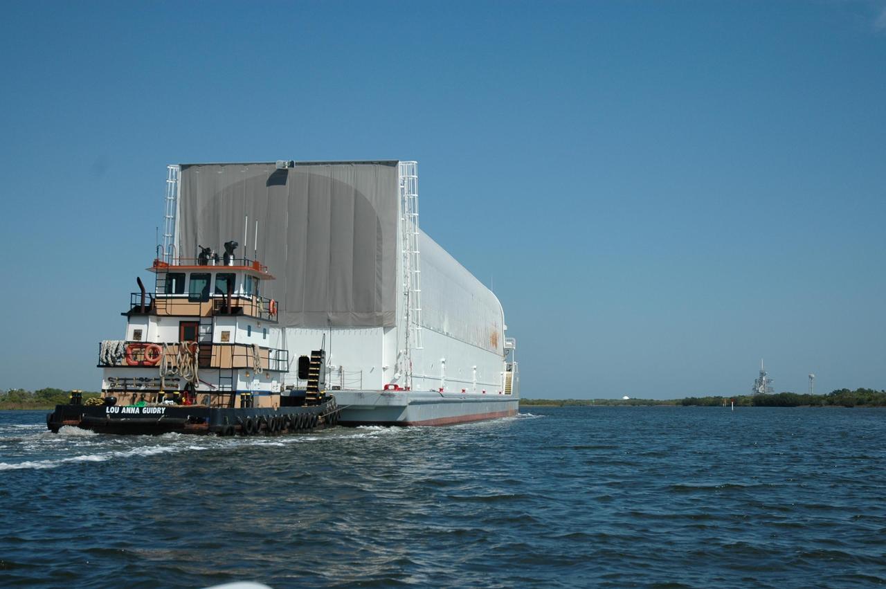
KENNEDY SPACE CENTER, FLA. -- The Pegasus barge is towed on the barge channel leading to the Launch Complex 39 Area. The barge's cargo is the external tank prepared for mission STS-118 by the Michoud Assembly Facility near New Orleans. Visible at right is one of the launch pads and the nearby water tower. The destination of the barge is the turn basin near the Vehicle Assembly Building where the tank will be offloaded and moved to the VAB. Photo credit: Dimitri Gerondidakis
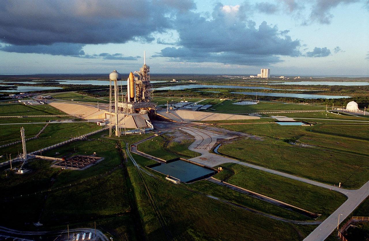
KENNEDY SPACE CENTER, Fla. -- A long view of Launch Complex 39 is caught by the early morning sun. Left of center is Launch Pad 39A with Space Shuttle Discovery. At its left is the 300,000-gallon water tank that is part of the sound suppression system. Hoses from the tank can be seen coiling under the pad, next to the opening of the flame trench, part of the flame detector system. In the foreground is a retention pond; another is at right center. At far right, the ball-shaped structure is a 850,000-gallon storage tank for the cryogenic liquid oxygen, one of the propellants of the orbiter’s main engines. On the horizon can be seen the 525-foot tall Vehicle Assembly Building

KENNEDY SPACE CENTER, Fla. -- A long view of Launch Complex 39 is caught by the early morning sun. Left of center is Launch Pad 39A with Space Shuttle Discovery. At its left is the 300,000-gallon water tank that is part of the sound suppression system. Hoses from the tank can be seen coiling under the pad, next to the opening of the flame trench, part of the flame detector system. In the foreground is a retention pond; another is at right center. At far right, the ball-shaped structure is a 850,000-gallon storage tank for the cryogenic liquid oxygen, one of the propellants of the orbiter’s main engines. On the horizon can be seen the 525-foot tall Vehicle Assembly Building
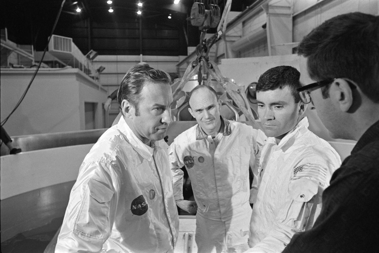
S70-24014 (17 Jan. 1970) --- The three prime crewmen of the Apollo 13 lunar landing mission stand by to participate in water egress training in a water tank in Building 260 at the Manned Spacecraft Center. They were (left to right) astronauts James A. Lovell Jr., commander; Thomas K. Mattingly II, command module pilot; and Fred W. Haise Jr., lunar module pilot.
Space Shuttle Discovery sits atop the Mobile Launch Platform on Launch Pad 39-B, with the Rotating Service Structure moved back, to await rollback decision. At the right is the 300,000-gallon water tank, part of the sound suppression water system used during launch. KSC managers developed a precautionary plan to roll back Discovery to the Vehicle Assembly Building in the event that Hurricane Georges threatens Central Florida. The decision was made in order to minimize risk and provide protection to the Space Shuttle, a national asset
S66-15743 (5 Jan. 1966) --- Astronaut David R. Scott, pilot of the Gemini-8 prime crew, undergoes water egress training in a special tank in building 260A at the Manned Spacecraft Center (MSC), Houston, Texas. An MSC swimmer assists in the training exercise. A boilerplate model of a Gemini spacecraft floats in the water beside Scott. Photo credit: NASA
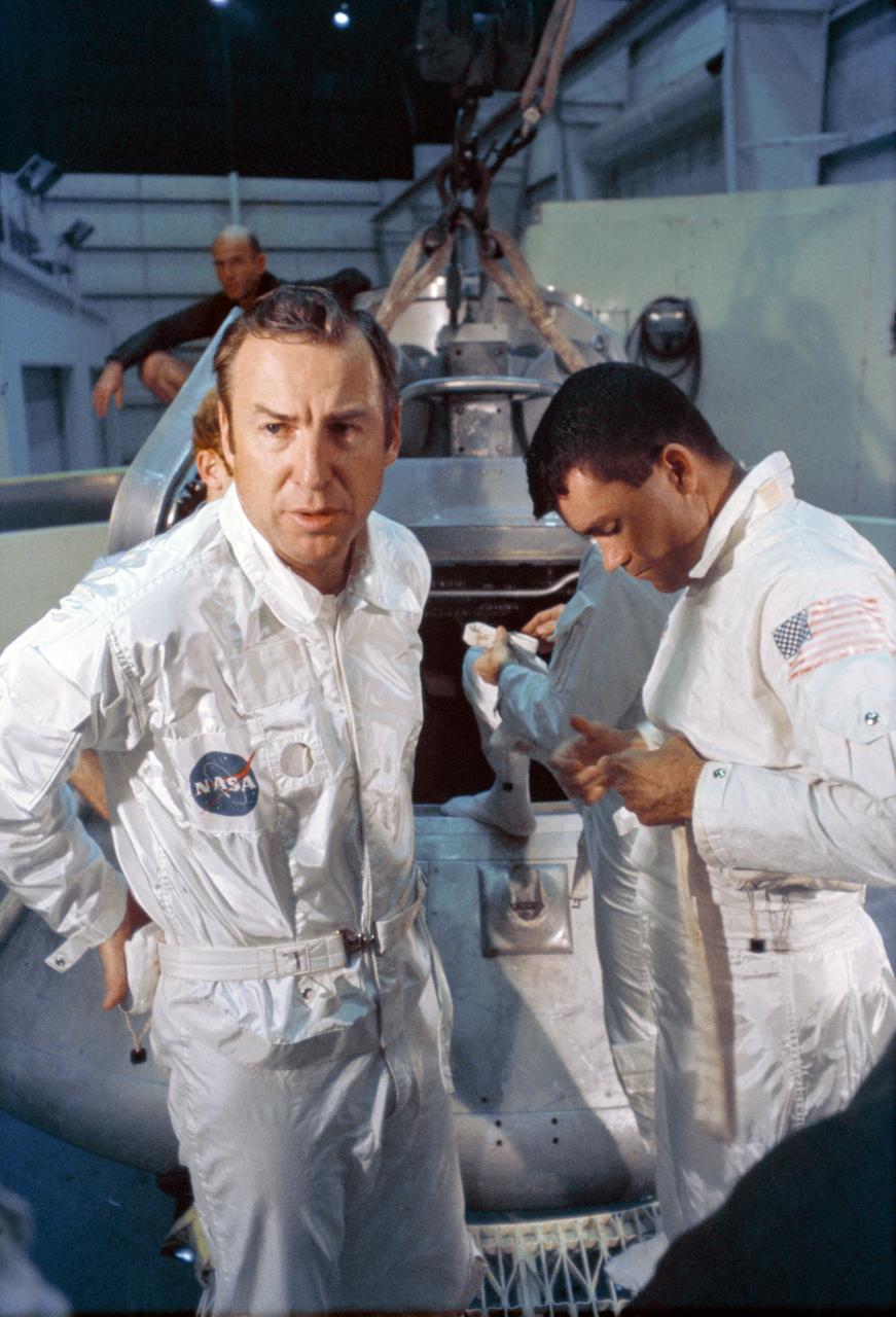
S70-24010 (17 Jan. 1970) --- The three prime crew members of the Apollo 13 lunar landing mission stand by to participate in water egress training in a water tank in Building 260 at the Manned Spacecraft Center (MSC). They are astronauts James A. Lovell Jr., (left) commander; Fred W. Haise Jr., (right) lunar module pilot; and Thomas K. Mattingly II (in background, obscured by Haise), command module pilot.
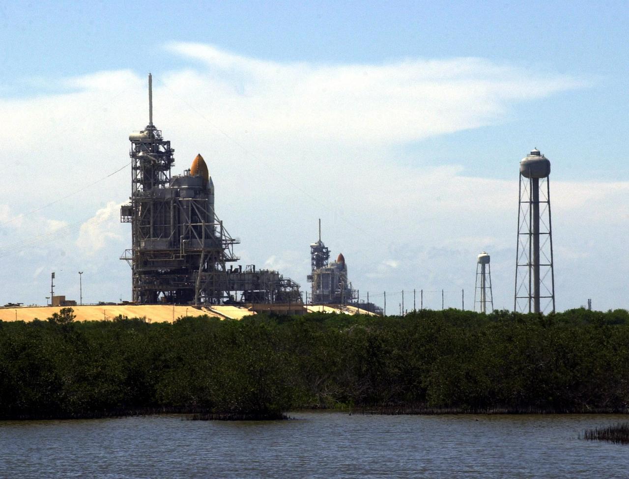
KENNEDY SPACE CENTER, Fla. -- Launch Pads 39A (foreground) and 39B are both seen in this photo, each with a Shuttle in place. Pad 39A holds Space Shuttle Discovery, which rolled out July 2 to be prepared for launch on mission STS-105 in August. Pad 39B holds Space Shuttle Atlantis, which is scheduled to launch Thursday, July 12, on mission STS-104. At right are the 290-foot water tanks that provide 300,000 gallons of water during liftoff. They are part of the sound suppression water system at each pad
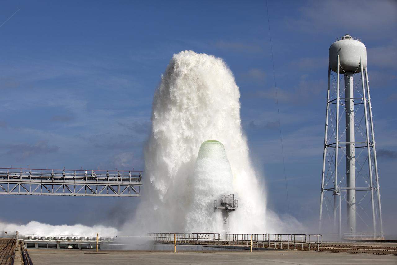
About 450,000 gallons of water flowed at high speed from a holding tank through new and modified piping and valves, the flame trench, flame deflector nozzles and mobile launcher interface risers during a wet flow test at Launch Pad 39B at NASA's Kennedy Space Center in Florida. At peak flow, the water reached about 100 feet in the air above the pad surface. The test was a milestone to confirm and baseline the performance of the Ignition Overpressure/Sound Suppression system. During launch of NASA's Space Launch System rocket and Orion spacecraft, the high-speed water flow will help protect the vehicle from the extreme acoustic and temperature environment during ignition and liftoff.
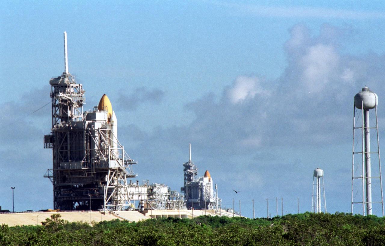
KENNEDY SPACE CENTER, Fla. -- Space Shuttle Discovery (foreground) and Space Shuttle Atlantis (background) both stand ready on their Launch Pads ( 39A and 39B respectively). Space Shuttle Discovery rolled out July 2 to be prepared for launch on mission STS-105 in August. Space Shuttle Atlantis is scheduled to launch Thursday, July 12, on mission STS-104. Towering above each Shuttle on the left is the 80-foot lightning rod that helps protect each Shuttle from lightning strikes. At right are the 290-foot water tanks that provide 300,000 gallons of water during liftoff. They are part of the sound suppression water system at each pad