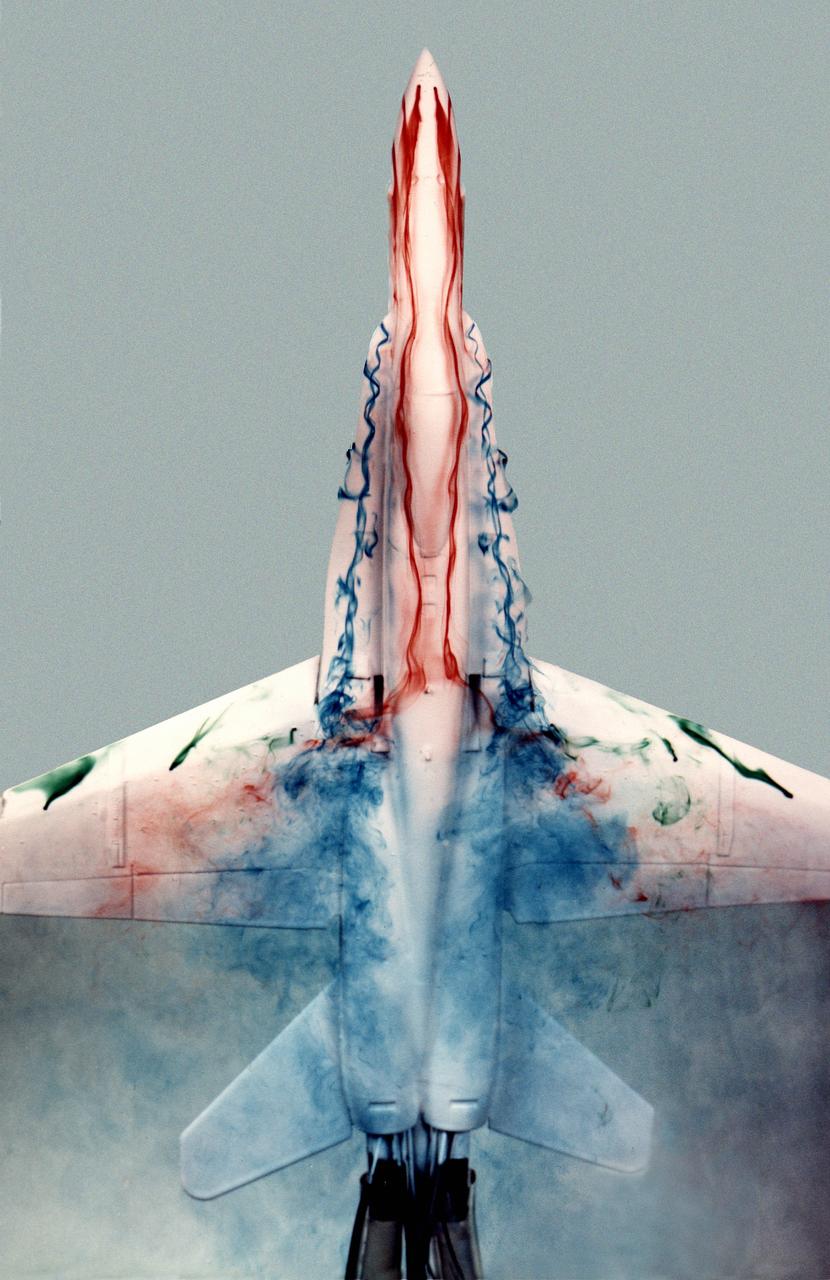
This image shows a plastic 1/48-scale model of an F-18 aircraft inside the "Water Tunnel" more formally known as the NASA Dryden Flow Visualization Facility. Water is pumped through the tunnel in the direction of normal airflow over the aircraft; then, colored dyes are pumped through tubes with needle valves. The dyes flow back along the airframe and over the airfoils highlighting their aerodynamic characteristics. The aircraft can also be moved through its pitch axis to observe airflow disruptions while simulating actual flight at high angles of attack. The Water Tunnel at NASA's Dryden Flight Research Center, Edwards, CA, became operational in 1983 when Dryden was a Flight Research Facility under the management of the Ames Research Center in Mountain View, CA. As a medium for visualizing fluid flow, water has played a significant role. Its use dates back to Leonardo da Vinci (1452-1519), the Renaissance Italian engineer, architect, painter, and sculptor. In more recent times, water tunnels have assisted the study of complex flows and flow-field interactions on aircraft shapes that generate strong vortex flows. Flow visualization in water tunnels assists in determining the strength of vortices, their location, and possible methods of controlling them. The design of the Dryden Water Tunnel imitated that of the Northrop Corporation's tunnel in Hawthorne, CA. Called the Flow Visualization Facility, the Dryden tunnel was built to assist researchers in understanding the aerodynamics of aircraft configured in such a way that they create strong vortex flows, particularly at high angles of attack. The tunnel provides results that compare well with data from aircraft in actual flight in another fluid-air. Other uses of the tunnel have included study of how such flight hardware as antennas, probes, pylons, parachutes, and experimental fixtures affect airflow. The facility has also been helpful in finding the best locations for emitting smoke from flight vehicles for flow vi
An AH-64 (Apache) Longbow fire control full size radar photographed during icing tests in the Icing Research wind tunnel. Built at the end of World War II, the Icing Research Tunnel is the oldest and largest refrigerated icing wind tunnel in the world. It can produce winds that travel up to 395 miles per hour and reach temperatures as low as -30 degrees Fahrenheit. The facility simulates ice formation during flight by spraying a cloud of super-cooled water droplets onto an aircraft component or model.
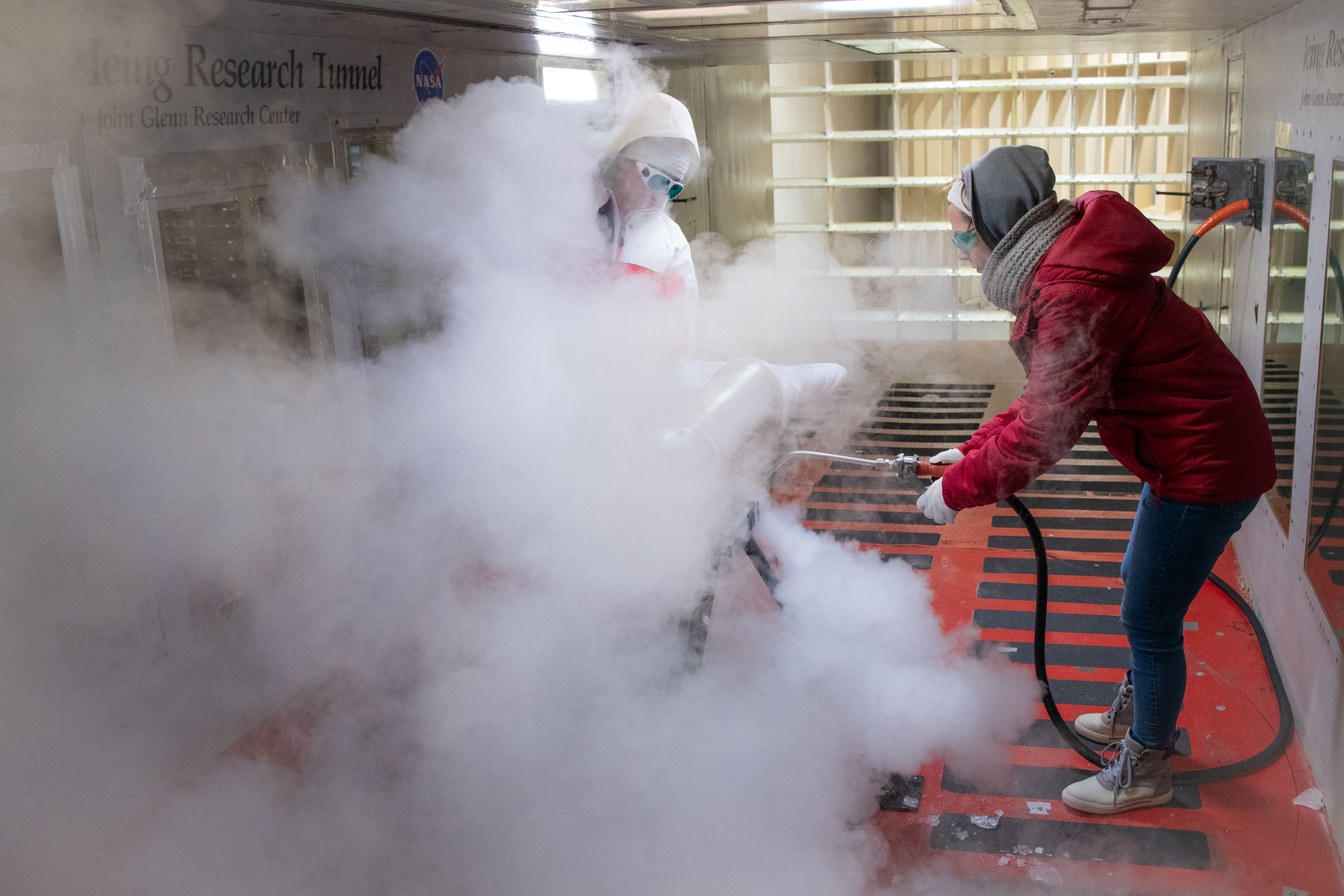
Test engineers clean the ice cloud detection probe in the Icing Research Tunnel in between test runs. Steam is used to melt the accumulated ice on the detection probe. The test engineers need to wear goggles to protect them from the laser light that the probe emits. The laser detects water content and ice particles in the cloud that the wind tunnel produces. This process is done to calibrate the tunnel for research by characterizing the cloud flow.
Emily Timko, featured in a Faces of NASA article, poses in the IRT (Icing Research Tunnel) where she works as a “cloud engineer”. She is a Mechanical Test Engineer and works to create unique water spray conditions that simulate icing clouds in the natural aircraft flight environment. Shown in the photo is a portion of the fan drive motor and fan blades that together drive the air through the wind tunnel.

Emily Timko, featured in a Faces of NASA article, poses in the IRT (Icing Research Tunnel) where she works as a “cloud engineer”. She is a Mechanical Test Engineer and works to create unique water spray conditions that simulate icing clouds in the natural aircraft flight environment. Shown in the photo is a portion of the fan drive motor and fan blades that together drive the air through the wind tunnel.
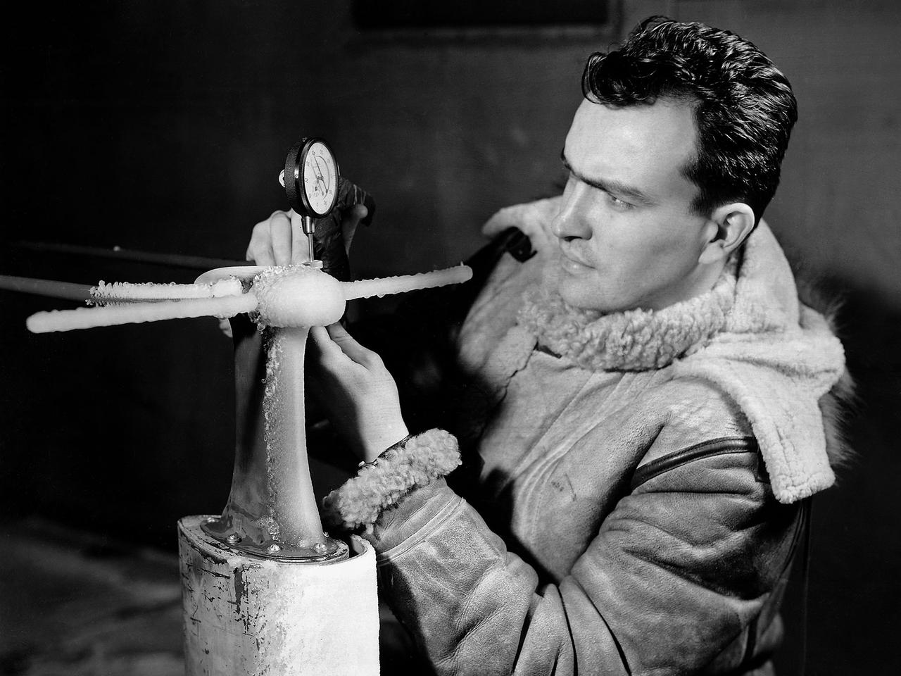
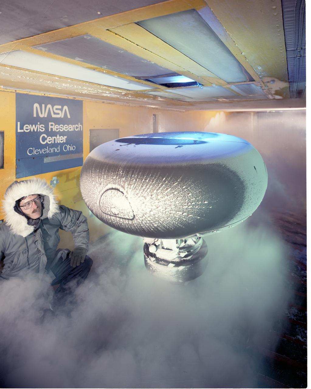
A National Advisory Committee for Aeronautics (NACA) researcher measures the ice thickness on a landing antenna model in the Icing Research Tunnel at the Aircraft Engine Research Laboratory. NACA design engineers added the Icing Research Tunnel to the original layout of the new Aircraft Engine Research Laboratory to take advantage of the massive refrigeration system being built for the Altitude Wind Tunnel. The Icing Research Tunnel was built to study the formation of ice on aircraft surfaces and methods of preventing or eradicating that ice. Ice buildup adds extra weight, effects aerodynamics, and sometimes blocks air flow through engines. The Icing Research Tunnel is a closed-loop atmospheric wind tunnel with a 6- by 9-foot test section. Carrier Corporation refrigeration equipment reduced the internal air temperature to -45 degrees F and a spray bar system injected water droplets into the air stream. The 24-foot diameter drive fan, seen in this photograph, created air flows velocities up to 400 miles per hour. The Icing Research Tunnel began testing in June of 1944. Early testing, seen in this photograph, studied ice accumulation on propellers and antenna of a military aircraft. The Icing Research Tunnel’s designers, however, struggled to develop a realistic spray system since they did not have access to data on the size of naturally occurring water droplets. The system would have to generate small droplets, distribute them uniformly throughout the airstream, and resist freezing and blockage. For five years a variety of different designs were painstakingly developed and tested before the system was perfected.
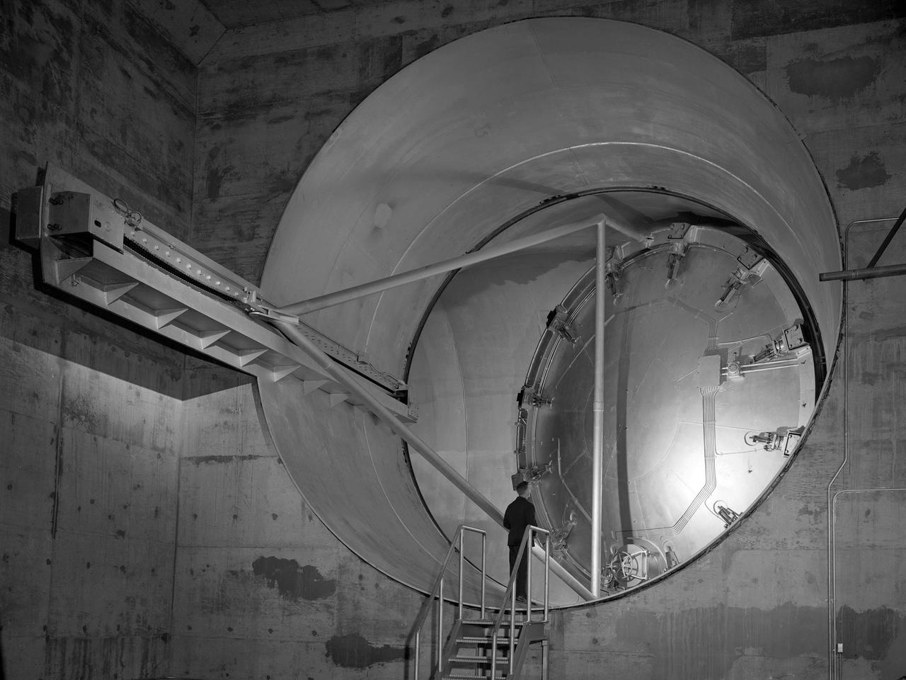
A 24-foot diameter swing valve is seen in an open position inside the new 10- by 10-Foot Supersonic Wind Tunnel at the National Advisory Committee for Aeronautics (NACA) Lewis Flight Propulsion Laboratory. The 10- by 10 was the most powerful propulsion wind tunnel in the nation. After over three years of construction the tunnel was ready to conduct its first tests in early 1956. The 10- by 10-foot tunnel was part of Congress’ Unitary Plan Act which coordinated wind tunnel construction at the NACA, Air Force, industry, and universities. The 10- by 10 was the largest of the three NACA tunnels built under the act. This large swinging valve is critical to the operation of the facility. In one position the valve seals off the tunnel exhaust, making the tunnel a closed circuit, which is used for aerodynamic testing of models. In its other position, the valve acts as a seal across the tunnel and leaves the tunnel exhaust open. This arrangement is used when engines are fired. The air going through the tunnel is taken from the atmosphere and returned to the atmosphere after one pass through the tunnel. Engines up to five feet in diameter can be tested in the 10- by 10-foot test section. Air flows up to Mach 3.5 can be fed through the test section by a 250,000-horsepower axial-flow compressor fan. The incoming air must be dehumidified and cooled so that the proper conditions are present for the test. A large air dryer with 1,890 tons of activated alumina soaks up 1.5 tons of water per minute from the air flow. A cooling apparatus equivalent to 250,000 household air conditioners is used to cool the air.
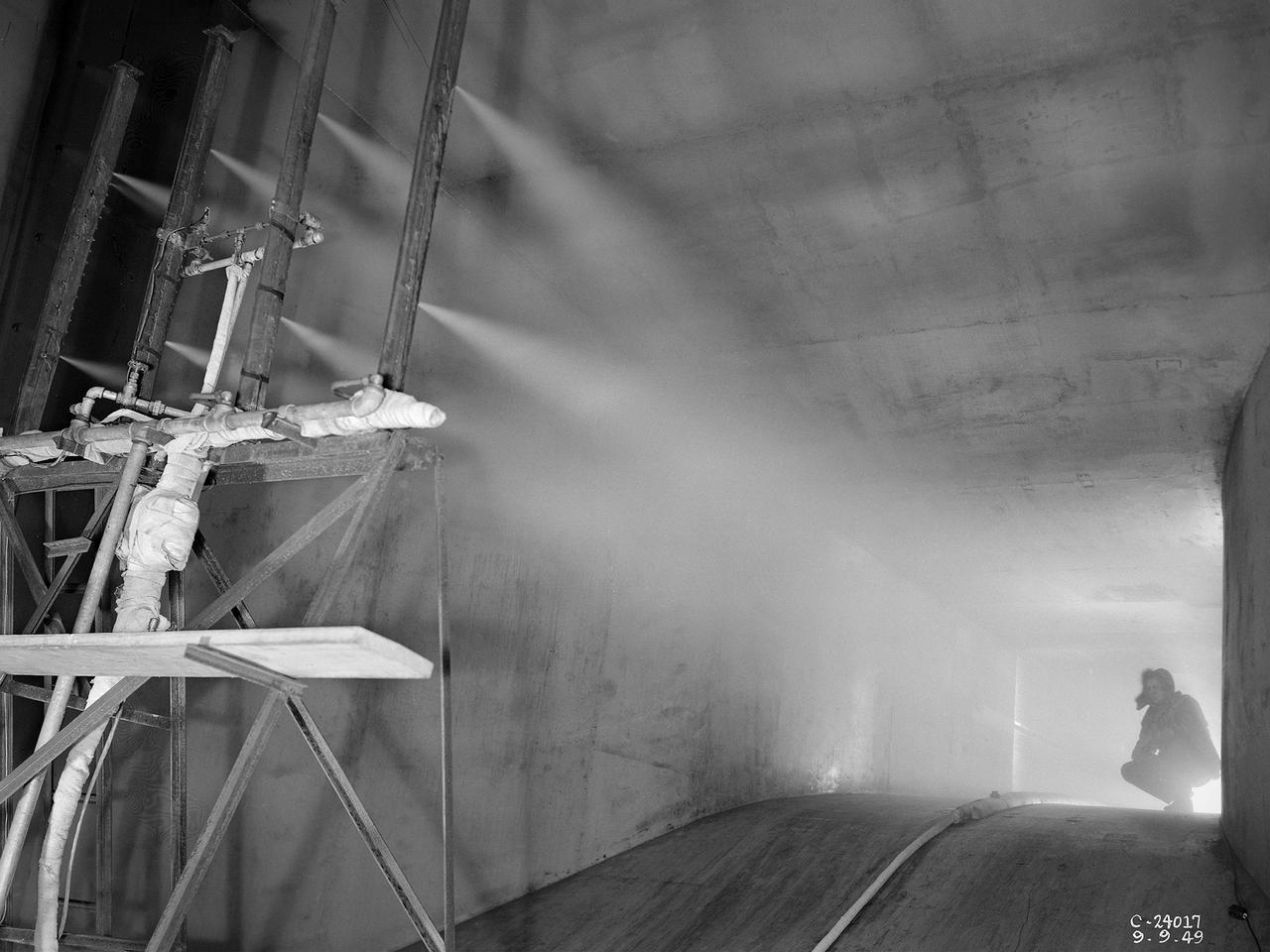
The spray bar system introduces water droplets into the Icing Research Tunnel’s air stream at the National Advisory Committee for Aeronautics (NACA) Lewis Flight Propulsion Laboratory. The icing tunnel was designed in the early 1940s to study ice accretion on airfoils and models. The Carrier Corporation designed a refrigeration system that reduced temperatures to -45° F. The tunnel’s drive fan generated speeds up to 400 miles per hour. The uniform injection of water droplets to the air was a key element of the facility’s operation. The system had to generate small droplets, distribute them uniformly throughout the airstream, and resist freezing and blockage. The Icing Research Tunnel’s designers struggled to develop a realistic spray system because they did not have access to data on the size of naturally occurring water droplets. For five years a variety of different designs were painstakingly developed and tested before the system was perfected. This photograph shows one of the trials using eight air-atomizing nozzles placed 48 feet upstream from the test section. A multi-cylinder device measured the size, liquid content, and distribution of the water droplets. The final system that was put into operation in 1950 included six horizontal spray bars with 80 nozzles that produced a 4- by 4-foot cloud in the test section. The Icing Research Tunnel produced excellent data throughout the 1950s and provided the basis for a hot air anti-icing system used on many transport aircraft.

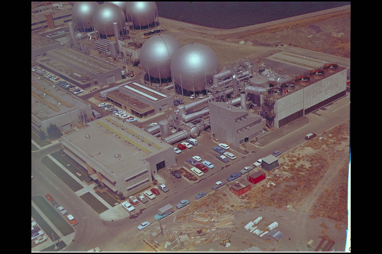
These compressors inside the Refrigeration Building at the National Advisory Committee for Aeronautics (NACA) Aircraft Engine Research Laboratory were used to generate cold temperatures in the Altitude Wind Tunnel (AWT) and Icing Research Tunnel. The AWT was a large facility that simulated actual flight conditions at high altitudes. The two primary aspects of altitude simulation are the reduction of the air pressure and the decrease of temperature. The Icing Research Tunnel was a smaller facility in which water droplets were added to the refrigerated air stream to simulate weather conditions that produced ice buildup on aircraft. The military pressured the NACA to complete the tunnels quickly so they could be of use during World War II. The NACA engineers struggled with the design of this refrigeration system, so Willis Carrier, whose Carrier Corporation had pioneered modern refrigeration, took on the project. The Carrier engineers devised the largest cooling system of its kind in the world. The system could lower the tunnels’ air temperature to –47⁰ F. The cooling system was powered by 14 Carrier and York compressors, seen in this photograph, which were housed in the Refrigeration Building between the two wind tunnels. The compressors converted the Freon 12 refrigerant into a liquid. The refrigerant was then pumped into zig-zag banks of cooling coils inside the tunnels’ return leg. The Freon absorbed heat from the airflow as it passed through the coils. The heat was transferred to the cooling water and sent to the cooling tower where it was dissipated into the atmosphere.
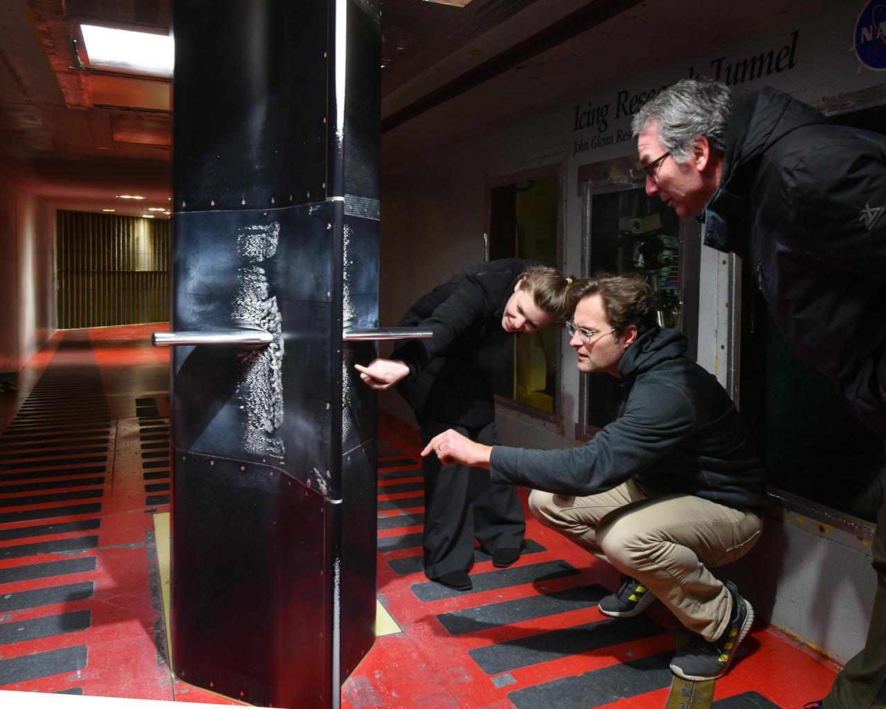
Pictured is a model to study the ice collection on struts in jet engines during flight. Researchers inspect the ice after the model encounters a simulated icing cloud during testing. Super cooled water created from the icing cloud that flows though the wind tunnel. The super cooled water forms ice on contact with the test model. Researchers then inspect the ice formation before laser scanning of the ice formation for further research and analysis.
The 10- by 10-Foot Supersonic Wind Tunnel at the NACA Lewis Flight Propulsion Laboratory was built under the Congressional Unitary Plan Act which coordinated wind tunnel construction at the NACA, Air Force, industry, and universities. The 10- by 10, which began operation in 1956, was the largest of the three NACA tunnels built under the act. Researchers could test engines up to five feet in diameter in the 10- by 10-foot test section. A 250,000-horsepower axial-flow compressor fan can generate airflows up to Mach 3.5 through the test section. The incoming air must be dehumidified and cooled so that the proper conditions are present for the test. A large air dryer with 1,890 tons of activated alumina soaks up 1.5 tons of water per minute from the airflow. A cooling apparatus equivalent to 250,000 household air conditioners is used to cool the air. The air heater is located just upstream from the test section. Natural gas is combusted in the tunnel to increase the air temperature. The system could only be employed when the tunnel was run in its closed-circuit propulsion mode.
Screwjacks located on the exterior of the second throat section in the 10- by 10-Foot Supersonic Wind Tunnel at the National Aeronautics and Space Administration (NASA) Lewis Research Center. The 10- by 10 tunnel was the most powerful propulsion wind tunnel in the country when it began operating in 1956. The facility can generate wind speeds from Mach 3 to 3.5. A flexible wall nozzle located just upstream from the test section can be adjusted using screw jacks to produce the desired air flow. The 61-foot long second throat, seen here from the outside, was located just beyond the test section. It slows the supersonic air flow down to prevent shock waves. The second throat’s side walls can be adjusted up to three inches on each side using these electrically-driven screwjacks. The air and the 1.25-inch thick walls are cooled by water injection. During the 1960s the 10- by 10-foot tunnel supported the development of virtually all US launch vehicle systems. It was used for Atlas-Centaur, Saturn rockets, and Atlas-Agena testing.
Panorama of the IRT engineering and ice cloud calibration team in the control room. Shown on the left are the data and system engineers. In the center with their backs to the camera are the wind tunnel operators who control the wind speed and super cooled water flow. In the center right of the photo is the video recording system and the test engineers. On the right side the test section can be see though the wind and the TV screen shows the pray bars that create the icing cloud.
Emily Timko, featured in a Faces of NASA article, poses in the IRT (Icing Research Tunnel) where she works as a “cloud engineer”. She is a Mechanical Test Engineer and works to create unique water spray conditions that simulate icing clouds in the natural aircraft flight environment. Shown in the photo is a test article of a rotating propeller configuration that the IRT researchers are investigating ice accretion with.
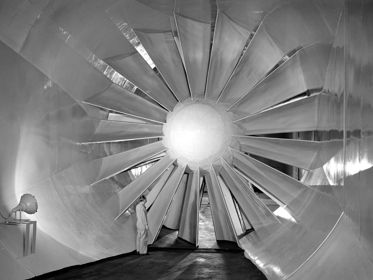
A researcher examines the drive fan inside the Icing Research Tunnel at the National Advisory Committee for Aeronautics (NACA) Flight Propulsion Research Laboratory in Cleveland, Ohio. The facility was built in the mid-1940s to simulate the atmospheric conditions that caused ice to build up on aircraft. Carrier Corporation refrigeration equipment reduced the internal air temperature to -45⁰ F, and a spray bar system injected water droplets into the air stream. The 24-foot diameter drive fan, seen in this photograph, created air flow velocities up to 400 miles per hour. The 1950s were prime years for the Icing Research Tunnel. NACA engineers had spent the 1940s trying to resolve the complexities of the spray bar system. The final system put into operation in 1950 included six horizontal spray bars with 80 nozzles that produced a 4- by 4-foot cloud in the test section. The icing tunnel was used for extensive testing of civilian and military aircraft components in the 1950s. The NACA also launched a major investigation of the various methods of heating leading edge surfaces. The hot-air anti-icing technology used on today’s commercial transports was largely developed in the facility during this period. Lewis researchers also made significant breakthroughs with icing on radomes and jet engines. Although the Icing Research Tunnel yielded major breakthroughs in the 1950s, the Lewis icing research program began tapering off as interest in the space program grew. The icing tunnel’s use declined in 1956 and 1957. The launch of Sputnik in October 1957 signaled the end of the facility’s operation. The icing staff was transferred to other research projects and the icing tunnel was temporarily mothballed.
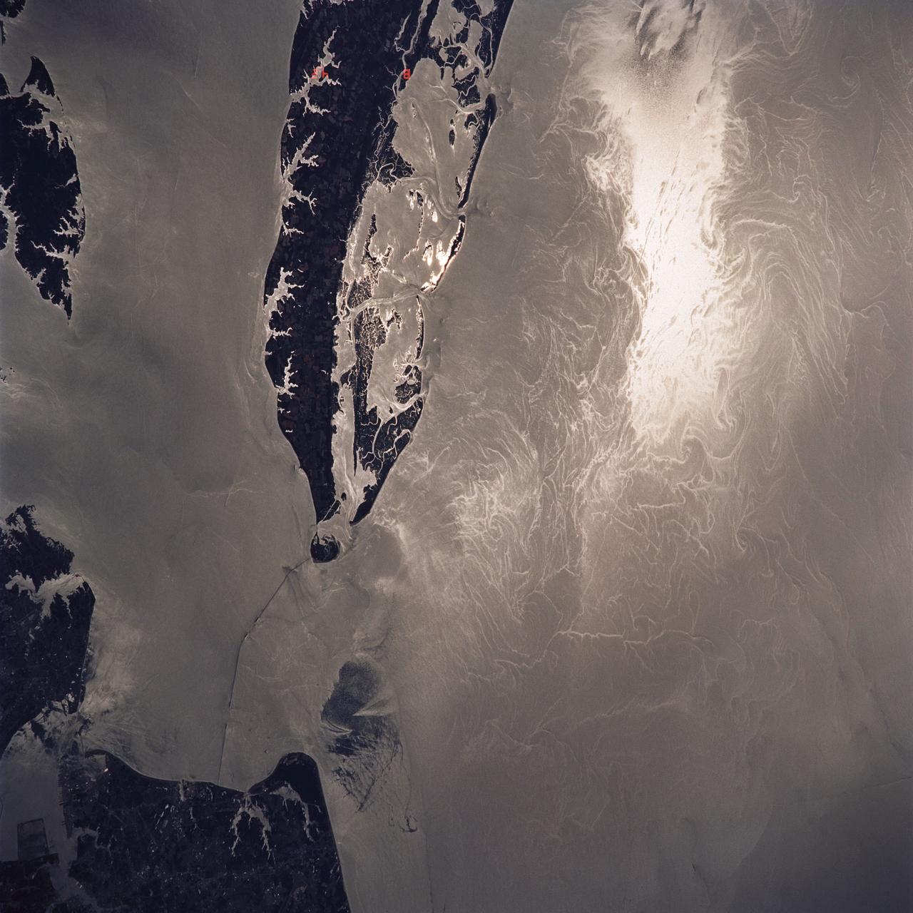
STS040-614-047 (5-14 June 1991) --- This image is of the Norfolk, Virginia -- Southern Delmarva Peninsula Southern Chesapeake Bay Area as seen in sunlight. The exposure is adjusted to emphasize the water patterns present. The outgoing tide generates considerable turbulence as it passes through the mouth of the bay. This is displayed by differences in reflective properties of the water surface due to differences in slope and turbidity. Ship wakes and the wakes of subsurface structures are seen clearly. The bridge tunnel system linking Norfolk with the peninsula and its effect on the system is quite apparent. Sunglint images over land areas were also acquired which emphasize land-water boundaries as demonstrated here in the small Delmarva inlets as a tool for wetland mapping, and river, lake and even pond description. During the first few days of the STS-40 mission the Eastern Seaboard of the United States was free of clouds and haze providing excellent photography of many of the major cities and the countryside of that area as well as the Gulf Stream.
Aerial view of Gasdynamics facility in 1964 and the 20 inch helium tunnel Part of the Thermal Protection Laboratory used to research materials for heat shield applications and for aerodynamic heating and materials studies of vehicles in planetary atmospheres. This laboratory is comprised of five separate facilities: an Aerodynamic Heating Tunnel, a Heat Transfer Tunnel, two Supersonic Turbulent Ducts, and a High-Power CO2 Gasdynamic Laser. All these facilities are driven by arc-heaters, with the exception of the large, combustion-type laser. The arc-heated facilities are powered by a 20 Megawatt DC power supply. Their effluent gas stream (test gases; Air, N2, He, CO2 and mixtures; flow rates from 0.05 to 5.0 lbs/sec) discharges into a five-stage stream-ejector-driven vacuum system. The vacuum system and power supply are common to the test faciities in building N-238. All of the facilities have high pressure water available at flow rates up to 4, 000 gals/min. The data obtained from these facilities are recorded on magnetic tape or oscillographs. All forms of data can be handled whether from thermo-couples, pressure cells, pyrometers, or radiometers, etc. in addition, closed circuit T. V. monitors and various film cameras are available. (operational since 1962)
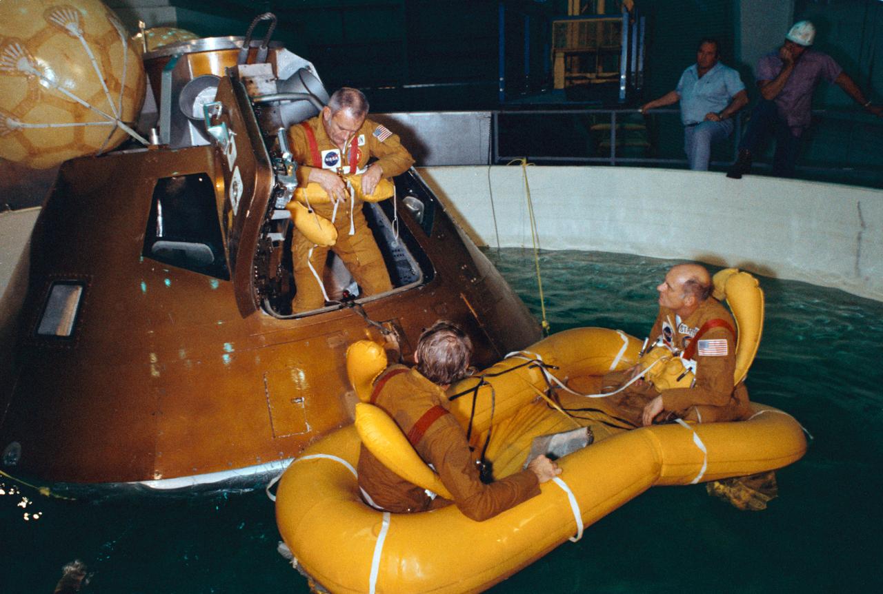
S75-23431 (8 March 1975) --- Astronaut Donald K. Slayton attaches his life preserver as he egresses an Apollo Command Module trainer in a water tank in Building 260 during water egress training at NASA's Johnson Space Center. The crewmen exit through the hatch when the CM is in this stable I (apex up) position; and they egress through the tunnel when the CM is in a stable II (apex down) position. Astronauts Vance D. Brand (on left) and Thomas P. Stafford have already egressed the trainer and are seated in a three-man life raft. This training session was part of the preparations for the joint U.S.-USSR Apollo-Soyuz Test Project docking mission in Earth orbit scheduled for July 1975. These three men compose the American ASTP prime crew. Stafford is the commander, Brand is the command module pilot, and Slayton is the docking module pilot.
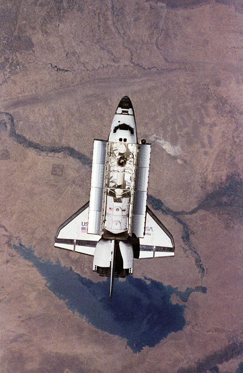
NM18-309-018 (28 June 1995) --- The Space Shuttle Atlantis orbits Earth at a point above Iraq as photographed by one of the Mir-18 crew members aboard Russia's Mir Space Station. The image was photographed prior to rendezvous and docking of the two spacecraft. The Spacelab science module and the tunnel connecting it to the crew cabin, as well as the added mechanism for interface with the Mir's docking system can be easily seen. The geography pictured is 60 miles northwest of Baghdad. The Buhayrat Ath Tharthar (reservoir) is the widest body of water visible. Also seen are the Tigris and Euphrates Rivers.
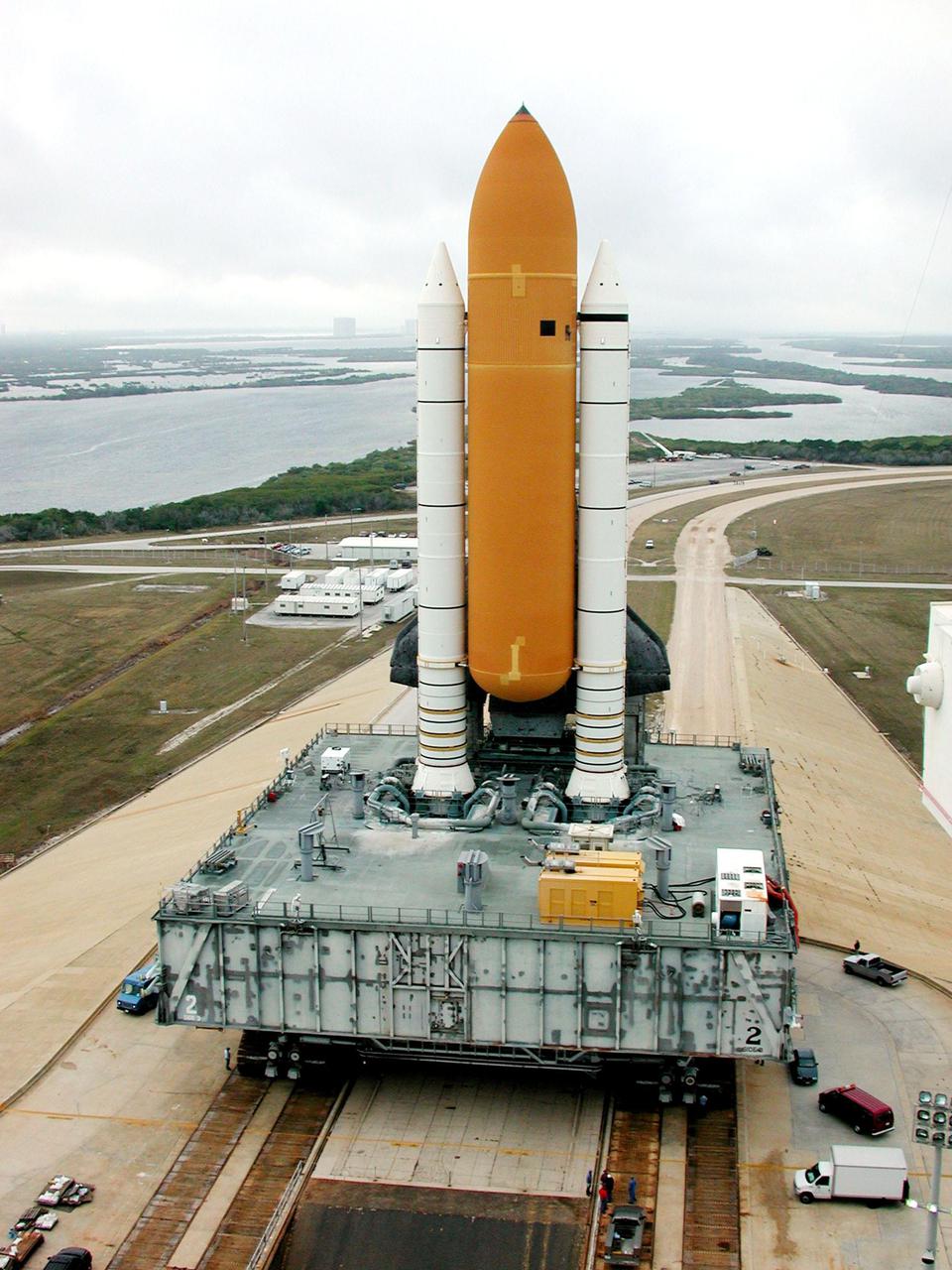
KENNEDY SPACE CENTER, FLA. -- Perched atop its Mobile Launcher Platform, Space Shuttle Atlantis moves back to the Vehicle Assembly Building, via the crawler-transporter underneath, along the crawlerway. The water in the background is part of the Banana River. Atlantis’ return to the VAB was determined by Shuttle managers so that inspections, continuity checks and X-ray analysis can be conducted on the 36 solid rocket booster cables located inside each booster’s system tunnel. An extensive evaluation of NASA’s SRB cable inventory revealed conductor damage in four (of about 200) cables on the shelf. The launch has been rescheduled no earlier than Feb. 6

One of the two primary coolers at the Propulsion Systems Laboratory at the National Advisory Committee for Aeronautics (NACA) Lewis Flight Propulsion Laboratory. Engines could be run in simulated altitude conditions inside the facility’s two 14-foot-diameter and 24-foot-long test chambers. The Propulsion Systems Laboratory was the nation’s only facility that could run large full-size engine systems in controlled altitude conditions. At the time of this photograph, construction of the facility had recently been completed. Although not a wind tunnel, the Propulsion Systems Laboratory generated high-speed airflow through the interior of the engine. The air flow was pushed through the system by large compressors, adjusted by heating or refrigerating equipment, and de-moisturized by air dryers. The exhaust system served two roles: reducing the density of the air in the test chambers to simulate high altitudes and removing hot gases exhausted by the engines being tested. It was necessary to reduce the temperature of the extremely hot engine exhaust before the air reached the exhauster equipment. As the air flow exited through exhaust section of the test chamber, it entered into the giant primary cooler seen in this photograph. Narrow fins or vanes inside the cooler were filled with water. As the air flow passed between the vanes, its heat was transferred to the cooling water. The cooling water was cycled out of the system, carrying with it much of the exhaust heat.
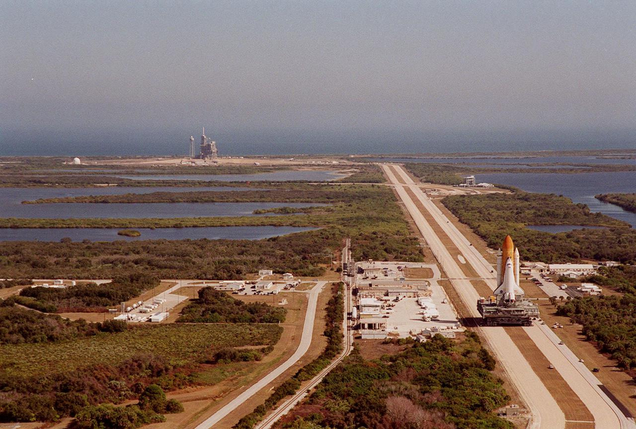
KENNEDY SPACE CENTER, FLA. -- Space Shuttle <a href='.._.._subjects_atlantis.htm'> Atlantis<_a> (right) inches its way at 1 mph atop the crawler-transporter back to the <a href='.._.._subjects_vab.htm'> Vehicle Assembly Building<_a> from <a href='.._.._subjects_lc39a.htm'> Launch Pad 39A<_a> (upper left). A panorama view from the top of the VAB shows the proximity of the pad to the Atlantic Ocean (background) plus the 3.4-mile crawlerway leading from the pad to the VAB. The water areas on both sides of the crawlerway are part of the Banana River. In the VAB workers will conduct inspections, make continuity checks and conduct X-ray analysis on the 36 solid rocket booster cables located inside each booster’s external system tunnel. An extensive evaluation of NASA’s SRB cable inventory revealed conductor damage in four (of about 200) cables on the shelf. Shuttle managers decided to prove the integrity of the system tunnel cables already on Atlantis before launching. The launch has been rescheduled no earlier than Feb. 6
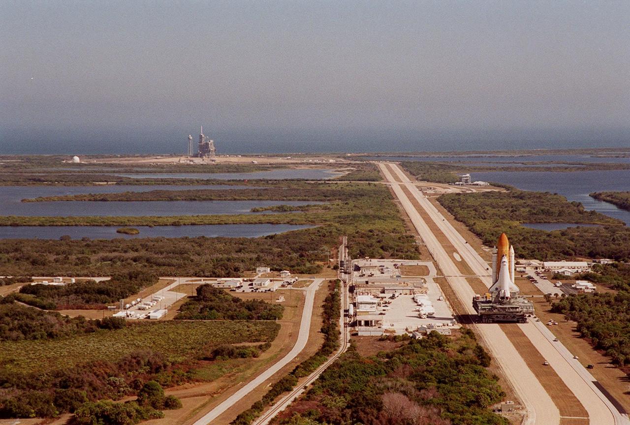
KENNEDY SPACE CENTER, FLA. -- Space Shuttle <a href="../../subjects/atlantis.htm"> Atlantis</a> (right) inches its way at 1 mph atop the crawler-transporter back to the <a href="../../subjects/vab.htm"> Vehicle Assembly Building</a> from <a href="../../subjects/lc39a.htm"> Launch Pad 39A</a> (upper left). A panorama view from the top of the VAB shows the proximity of the pad to the Atlantic Ocean (background) plus the 3.4-mile crawlerway leading from the pad to the VAB. The water areas on both sides of the crawlerway are part of the Banana River. In the VAB workers will conduct inspections, make continuity checks and conduct X-ray analysis on the 36 solid rocket booster cables located inside each booster’s external system tunnel. An extensive evaluation of NASA’s SRB cable inventory revealed conductor damage in four (of about 200) cables on the shelf. Shuttle managers decided to prove the integrity of the system tunnel cables already on Atlantis before launching. The launch has been rescheduled no earlier than Feb. 6

S69-26149 (6 March 1969) --- Astronaut James A. McDivitt, Apollo 9 commander, is seen inside the Lunar Module "Spider" drinking from a hand water dispenser in this photograph from the second live television transmission from Apollo 9. Astronaut Russell L. Schweickart, lunar module pilot, is in the left background. The telecast was made early Thursday afternoon on the fourth day in space. At this moment Apollo 9 was orbiting Earth with the Command and Service Modules docked nose-to-nose with the Lunar Module. Astronaut David R. Scott, command module pilot, remained at the controls in the Command Module "Gumdrop" while the other two astronauts checked out the Lunar Module. McDivitt and Schweickart moved into the Lunar Module from the Command Module by way of the docking tunnel.
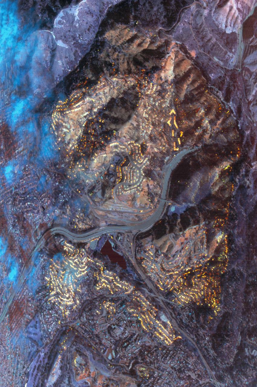
This data was acquired by the NASA C-130B Earth Resources Survey aircraft flying at 6,000 ft. mean sea level at 10:26 a. m. on October 21, 1991. The sensor used was the NS001 Thermatic Mapper Simulator, with a ground resolution of 4.6 meters (15ft). The image area is 4.7 x 3.2 km (2.9 x 2 mi.). The area covered is the Oakland Berkeley Hills near the Caldecott Tunnel (Upper right). Targets over 600 degrees centrigrade are shown as yellow in this composite of three infrared bands (11.6, 2.3, & 1.6 microns). A large condominium complex at the upper right is completely consumed. Areas already burned off sow as pale red. The blue clouds at left are condensed water vapor within the smoke plume, which blocks the infrared wavelength; the smoke itself is transparent. Many hundreds of individual structures can be seen either actively burning or as heat of smouldering debris.
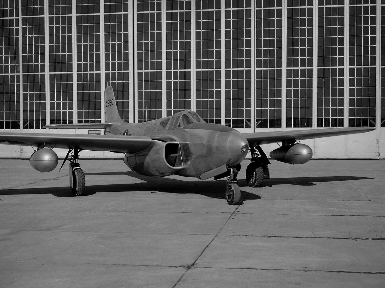
A Bell P-59B Airacomet sits beside the hangar at the National Advisory Committee for Aeronautics (NACA) Lewis Flight Propulsion Laboratory. In 1942 the Bell XP-59A Airacomet became the first jet aircraft in the US. The Airacomet incorporated centrifugal turbojet engines that were based on British plans secretly brought to the US in 1941. A Bell test pilot flew the XP-59A for the first time at Muroc Lake, California in October 1942. The General Electric I-16 engines proved to be problematic. In an effort to increase the engine performance, an Airacomet was secretly brought to Cleveland in early 1944 for testing in the Altitude Wind Tunnel. A series of tunnel investigations in February and March resulted in a 25-percent increase in the I-16 engine’s performance. Nonetheless, Bell’s 66 Airacomets never made it into combat. A second, slightly improved Airacomet, a P-59B, was transferred to NACA Lewis just after the war in September 1945. The P-59B was used over the next three years to study general jet thrust performance and thrust augmentation devices such as afterburners and water/alcohol injection. The P-59B flights determined the proper alcohol and water mixture and injection rate to produce a 21-percent increase in thrust. Since the extra boost would be most useful for takeoffs, a series of ground-based tests with the aircraft ensued. It was determined that the runway length for takeoffs could be reduced by as much as 15 percent. The P-59B used for the tests is now on display at the Air Force Museum at Wright Patterson.
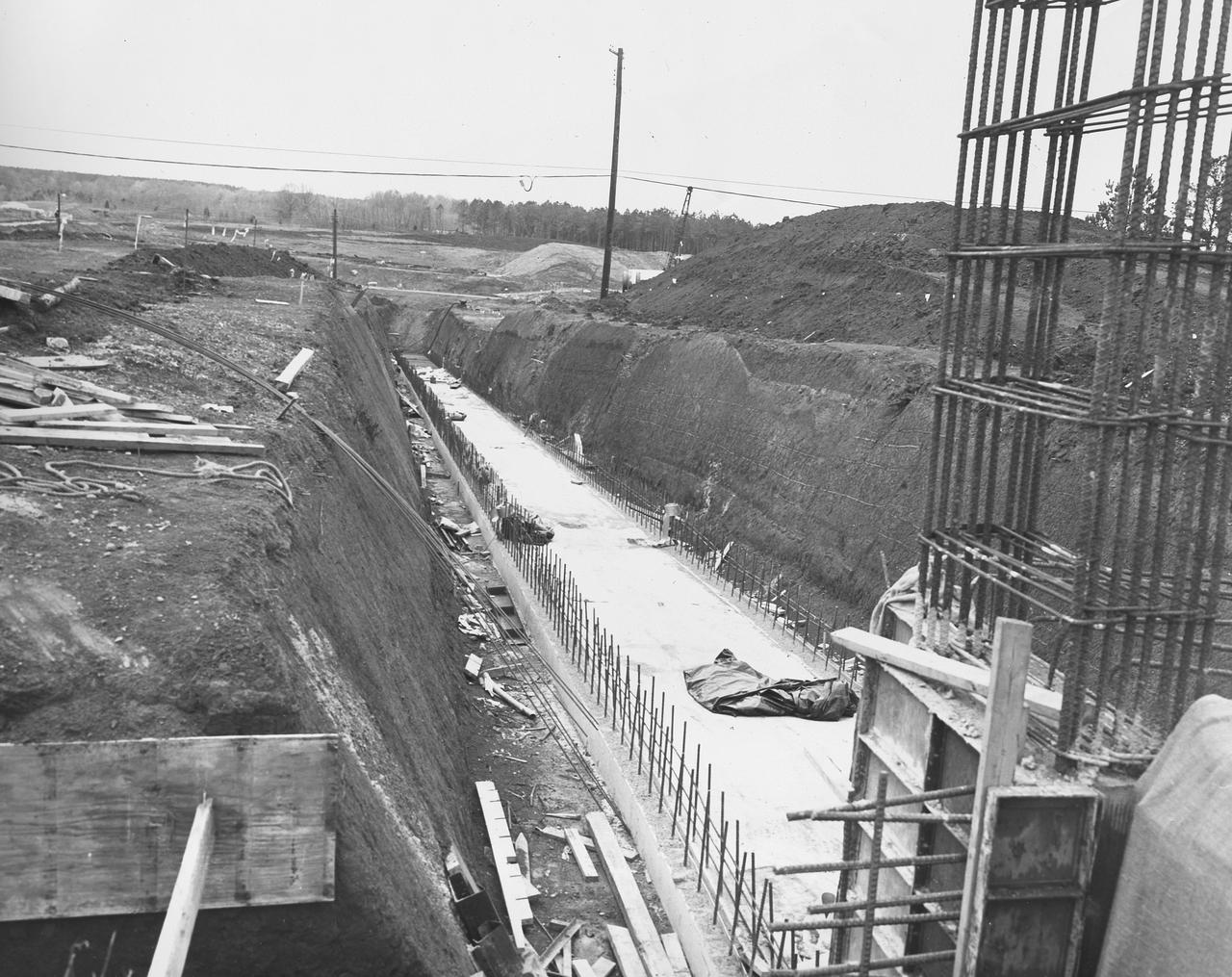
At its founding, the Marshall Space Flight Center (MSFC) inherited the Army’s Jupiter and Redstone test stands, but much larger facilities were needed for the giant stages of the Saturn V. From 1960 to 1964, the existing stands were remodeled and a sizable new test area was developed. The new comprehensive test complex for propulsion and structural dynamics was unique within the nation and the free world, and they remain so today because they were constructed with foresight to meet the future as well as on going needs. Construction of the S-IC Static test stand complex began in 1961 in the west test area of MSFC, and was completed in 1964. The S-IC static test stand was designed to develop and test the 138-ft long and 33-ft diameter Saturn V S-IC first stage, or booster stage, weighing in at 280,000 pounds. Required to hold down the brute force of a 7,500,000-pound thrust produced by 5 F-1 engines, the S-IC static test stand was designed and constructed with the strength of hundreds of tons of steel and 12,000,000 pounds of cement, planted down to bedrock 40 feet below ground level. The foundation walls, constructed with concrete and steel, are 4 feet thick. The base structure consists of four towers with 40-foot-thick walls extending upward 144 feet above ground level. The structure was topped by a crane with a 135-foot boom. With the boom in the upright position, the stand was given an overall height of 405 feet, placing it among the highest structures in Alabama at the time. In addition to the stand itself, related facilities were constructed during this time. Built directly east of the test stand was the Block House, which served as the control center for the test stand. The two were connected by a narrow tunnel which housed the cables for the controls. Again to the east, just south of the Block House, was a newly constructed Pump House. Its function was to provide water to the stand to prevent melting damage during testing. The water was sprayed through small holes in the stand’s 1900 ton water deflector at the rate of 320,000 gallons per minute. This photograph, taken Aril 16, 1962, depicts the water line area through which the pump house delivered water to the stand.
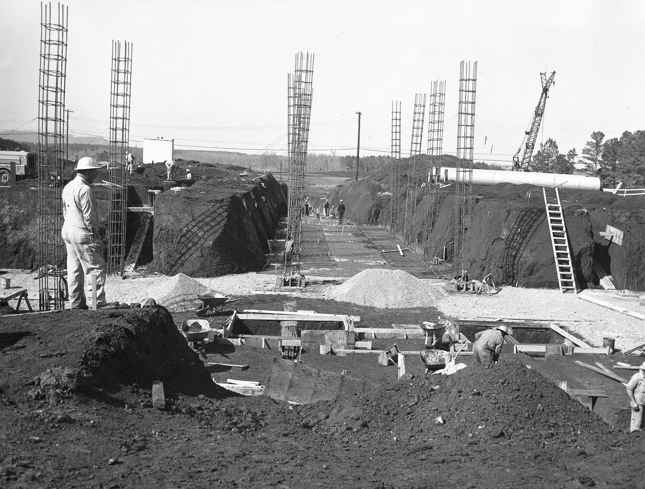
At its founding, the Marshall Space Flight Center (MSFC) inherited the Army’s Jupiter and Redstone test stands, but much larger facilities were needed for the giant stages of the Saturn V. From 1960 to 1964, the existing stands were remodeled and a sizable new test area was developed. The new comprehensive test complex for propulsion and structural dynamics was unique within the nation and the free world, and they remain so today because they were constructed with foresight to meet the future as well as on going needs. Construction of the S-IC Static test stand complex began in 1961 in the west test area of MSFC, and was completed in 1964. The S-IC static test stand was designed to develop and test the 138-ft long and 33-ft diameter Saturn V S-IC first stage, or booster stage, weighing in at 280,000 pounds. Required to hold down the brute force of a 7,500,000-pound thrust produced by 5 F-1 engines, the S-IC static test stand was designed and constructed with the strength of hundreds of tons of steel and 12,000,000 pounds of cement, planted down to bedrock 40 feet below ground level. The foundation walls, constructed with concrete and steel, are 4 feet thick. The base structure consists of four towers with 40-foot-thick walls extending upward 144 feet above ground level. The structure was topped by a crane with a 135-foot boom. With the boom in the upright position, the stand was given an overall height of 405 feet, placing it among the highest structures in Alabama at the time. In addition to the stand itself, related facilities were constructed during this time. Built directly east of the test stand was the Block House, which served as the control center for the test stand. The two were connected by a narrow tunnel which housed the cables for the controls. Again to the east, just south of the Block House, was a newly constructed Pump House. Its function was to provide water to the stand to prevent melting damage during testing. The water was sprayed through small holes in the stand’s 1900 ton water deflector at the rate of 320,000 gallons per minute. In this photo, taken March 20, 1962, construction of the Pump House area is well underway.
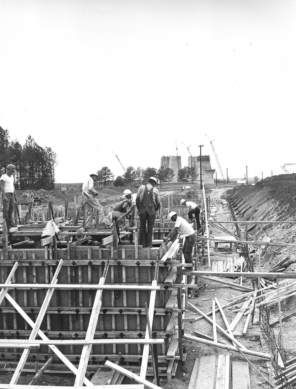
At its founding, the Marshall Space Flight Center (MSFC) inherited the Army’s Jupiter and Redstone test stands, but much larger facilities were needed for the giant stages of the Saturn V. From 1960 to 1964, the existing stands were remodeled and a sizable new test area was developed. The new comprehensive test complex for propulsion and structural dynamics was unique within the nation and the free world, and they remain so today because they were constructed with foresight to meet the future as well as on going needs. Construction of the S-IC Static test stand complex began in 1961 in the west test area of MSFC, and was completed in 1964. The S-IC static test stand was designed to develop and test the 138-ft long and 33-ft diameter Saturn V S-IC first stage, or booster stage, weighing in at 280,000 pounds. Required to hold down the brute force of a 7,500,000-pound thrust produced by 5 F-1 engines, the S-IC static test stand was designed and constructed with the strength of hundreds of tons of steel and 12,000,000 pounds of cement, planted down to bedrock 40 feet below ground level. The foundation walls, constructed with concrete and steel, are 4 feet thick. The base structure consists of four towers with 40-foot-thick walls extending upward 144 feet above ground level. The structure was topped by a crane with a 135-foot boom. With the boom in the upright position, the stand was given an overall height of 405 feet, placing it among the highest structures in Alabama at the time. In addition to the stand itself, related facilities were constructed during this time. Built directly east of the test stand was the Block House, which served as the control center for the test stand. The two were connected by a narrow access tunnel which housed the cables for the controls. Again to the east, just south of the Block House, was a newly constructed Pump House. Its function was to provide water to the stand to prevent melting damage during testing. The water was sprayed through small holes in the stand’s 1900 ton water deflector at the rate of 320,000 gallons per minute. In this photo, taken May 22, 1963, the Pump House is undergoing construction.
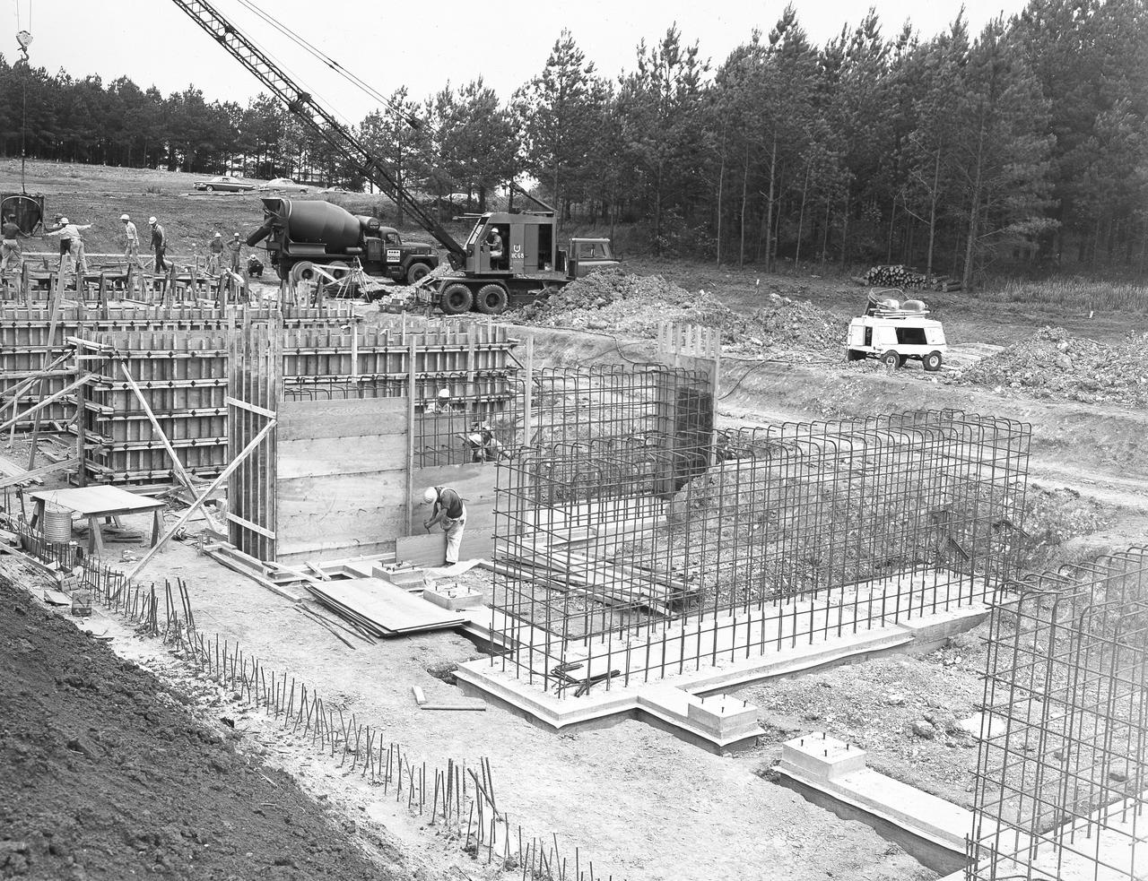
At its founding, the Marshall Space Flight Center (MSFC) inherited the Army’s Jupiter and Redstone test stands, but much larger facilities were needed for the giant stages of the Saturn V. From 1960 to 1964, the existing stands were remodeled and a sizable new test area was developed. The new comprehensive test complex for propulsion and structural dynamics was unique within the nation and the free world, and they remain so today because they were constructed with foresight to meet the future as well as on going needs. Construction of the S-IC Static test stand complex began in 1961 in the west test area of MSFC, and was completed in 1964. The S-IC static test stand was designed to develop and test the 138-ft long and 33-ft diameter Saturn V S-IC first stage, or booster stage, weighing in at 280,000 pounds. Required to hold down the brute force of a 7,500,000-pound thrust produced by 5 F-1 engines, the S-IC static test stand was designed and constructed with the strength of hundreds of tons of steel and 12,000,000 pounds of cement, planted down to bedrock 40 feet below ground level. The foundation walls, constructed with concrete and steel, are 4 feet thick. The base structure consists of four towers with 40-foot-thick walls extending upward 144 feet above ground level. The structure was topped by a crane with a 135-foot boom. With the boom in the upright position, the stand was given an overall height of 405 feet, placing it among the highest structures in Alabama at the time. In addition to the stand itself, related facilities were constructed during this time. Built directly east of the test stand was the Block House, which served as the control center for the test stand. The two were connected by a narrow access tunnel which housed the cables for the controls. Again to the east, just south of the Block House, was a newly constructed Pump House. Its function was to provide water to the stand to prevent melting damage during testing. The water was sprayed through small holes in the stand’s 1900 ton water deflector at the rate of 320,000 gallons per minute. In this photo, taken May 22, 1963, the Pump House is undergoing construction.
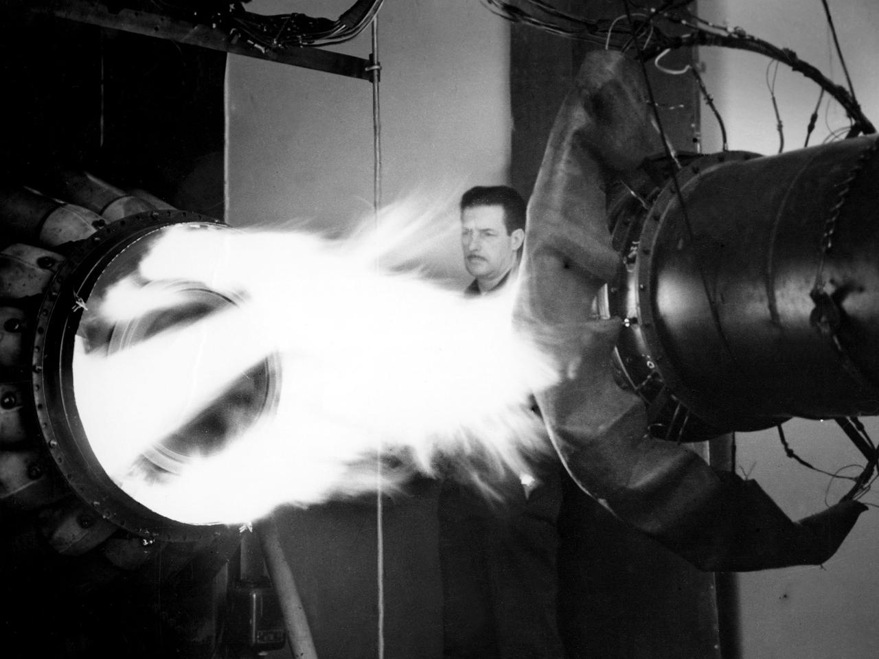
A mechanic watches the firing of a General Electric I-40 turbojet at the National Advisory Committee for Aeronautics (NACA) Lewis Flight Propulsion Laboratory. The military selected General Electric’s West Lynn facility in 1941 to secretly replicate the centrifugal turbojet engine designed by British engineer Frank Whittle. General Electric’s first attempt, the I-A, was fraught with problems. The design was improved somewhat with the subsequent I-16 engine. It was not until the engine's next reincarnation as the I-40 in 1943 that General Electric’s efforts paid off. The 4000-pound thrust I-40 was incorporated into the Lockheed Shooting Star airframe and successfully flown in June 1944. The Shooting Star became the US’s first successful jet aircraft and the first US aircraft to reach 500 miles per hour. NACA Lewis studied all of General Electric’s centrifugal turbojet models during the 1940s. In 1945 the entire Shooting Star aircraft was investigated in the Altitude Wind Tunnel. Engine compressor performance and augmentation by water injection; comparison of different fuel blends in a single combustor; and air-cooled rotors were studied. The mechanic in this photograph watches the firing of a full-scale I-40 in the Jet Propulsion Static Laboratory. The facility was quickly built in 1943 specifically in order to test the early General Electric turbojets. The I-A was secretly analyzed in the facility during the fall of 1943.
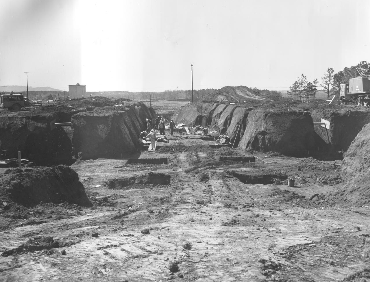
At its founding, the Marshall Space Flight Center (MSFC) inherited the Army’s Jupiter and Redstone test stands, but much larger facilities were needed for the giant stages of the Saturn V. From 1960 to 1964, the existing stands were remodeled and a sizable new test area was developed. The new comprehensive test complex for propulsion and structural dynamics was unique within the nation and the free world, and they remain so today because they were constructed with foresight to meet the future as well as on going needs. Construction of the S-IC Static test stand complex began in 1961 in the west test area of MSFC, and was completed in 1964. The S-IC static test stand was designed to develop and test the 138-ft long and 33-ft diameter Saturn V S-IC first stage, or booster stage, weighing in at 280,000 pounds. Required to hold down the brute force of a 7,500,000-pound thrust produced by 5 F-1 engines, the S-IC static test stand was designed and constructed with the strength of hundreds of tons of steel and 12,000,000 pounds of cement, planted down to bedrock 40 feet below ground level. The foundation walls, constructed with concrete and steel, are 4 feet thick. The base structure consists of four towers with 40-foot-thick walls extending upward 144 feet above ground level. The structure was topped by a crane with a 135-foot boom. With the boom in the upright position, the stand was given an overall height of 405 feet, placing it among the highest structures in Alabama at the time. In addition to the stand itself, related facilities were constructed during this time. Built directly east of the test stand was the Block House, which served as the control center for the test stand. The two were connected by a narrow access tunnel which housed the cables for the controls. Again to the east, just south of the Block House, was a newly constructed Pump House. Its function was to provide water to the stand to prevent melting damage during testing. The water was sprayed through small holes in the S-IC test stand’s 1900 ton water deflector at the rate of 320,000 gallons per minute. This photo, taken March 15, 1962, shows the excavation of the water line area connecting the Pump House to the S-IC test stand.
At its founding, the Marshall Space Flight Center (MSFC) inherited the Army’s Jupiter and Redstone test stands, but much larger facilities were needed for the giant stages of the Saturn V. From 1960 to 1964, the existing stands were remodeled and a sizable new test area was developed. The new comprehensive test complex for propulsion and structural dynamics was unique within the nation and the free world, and they remain so today because they were constructed with foresight to meet the future as well as on going needs. Construction of the S-IC Static test stand complex began in 1961 in the west test area of MSFC, and was completed in 1964. The S-IC static test stand was designed to develop and test the 138-ft long and 33-ft diameter Saturn V S-IC first stage, or booster stage, weighing in at 280,000 pounds. Required to hold down the brute force of a 7,500,000-pound thrust produced by 5 F-1 engines, the S-IC static test stand was designed and constructed with the strength of hundreds of tons of steel and 12,000,000 pounds of cement, planted down to bedrock 40 feet below ground level. The foundation walls, constructed with concrete and steel, are 4 feet thick. The base structure consists of four towers with 40-foot-thick walls extending upward 144 feet above ground level. The structure was topped by a crane with a 135-foot boom. With the boom in the upright position, the stand was given an overall height of 405 feet, placing it among the highest structures in Alabama at the time. In addition to the stand itself, related facilities were constructed during this time. Built directly east of the test stand was the Block House, which served as the control center for the test stand. The two were connected by a narrow access tunnel which housed the cables for the controls. Again to the east, just south of the Block House, was a newly constructed Pump House. Its function was to provide water to the stand to prevent melting damage during testing. The water was sprayed through small holes in the stand’s 1900 ton water deflector at the rate of 320,000 gallons per minute. In this photo, NASA employee Orville Driver is demonstrating the size of the 8 foot diameter water lines used for this purpose.
At its founding, the Marshall Space Flight Center (MSFC) inherited the Army’s Jupiter and Redstone test stands, but much larger facilities were needed for the giant stages of the Saturn V. From 1960 to 1964, the existing stands were remodeled and a sizable new test area was developed. The new comprehensive test complex for propulsion and structural dynamics was unique within the nation and the free world, and they remain so today because they were constructed with foresight to meet the future as well as on going needs. Construction of the S-IC Static test stand complex began in 1961 in the west test area of MSFC, and was completed in 1964. The S-IC static test stand was designed to develop and test the 138-ft long and 33-ft diameter Saturn V S-IC first stage, or booster stage, weighing in at 280,000 pounds. Required to hold down the brute force of a 7,500,000-pound thrust produced by 5 F-1 engines, the S-IC static test stand was designed and constructed with the strength of hundreds of tons of steel and 12,000,000 pounds of cement, planted down to bedrock 40 feet below ground level. The foundation walls, constructed with concrete and steel, are 4 feet thick. The base structure consists of four towers with 40-foot-thick walls extending upward 144 feet above ground level. The structure was topped by a crane with a 135-foot boom. With the boom in the upright position, the stand was given an overall height of 405 feet, placing it among the highest structures in Alabama at the time. In addition to the stand itself, related facilities were constructed during this time. Built directly east of the test stand was the Block House, which served as the control center for the test stand. The two were connected by a narrow access tunnel which housed the cables for the controls. Again to the east, just south of the Block House, was a newly constructed Pump House. Its function was to provide water to the stand to prevent melting damage during testing. The water was sprayed through small holes in the stand’s 1900 ton water deflector at the rate of 320,000 gallons per minute. This photo, taken April 4, 1963, depicts the portion of the massive water line that was installed into the S-IC test Stand.
At its founding, the Marshall Space Flight Center (MSFC) inherited the Army’s Jupiter and Redstone test stands, but much larger facilities were needed for the giant stages of the Saturn V. From 1960 to 1964, the existing stands were remodeled and a sizable new test area was developed. The new comprehensive test complex for propulsion and structural dynamics was unique within the nation and the free world, and they remain so today because they were constructed with foresight to meet the future as well as on going needs. Construction of the S-IC Static test stand complex began in 1961 in the west test area of MSFC, and was completed in 1964. The S-IC static test stand was designed to develop and test the 138-ft long and 33-ft diameter Saturn V S-IC first stage, or booster stage, weighing in at 280,000 pounds. Required to hold down the brute force of a 7,500,000-pound thrust produced by 5 F-1 engines, the S-IC static test stand was designed and constructed with the strength of hundreds of tons of steel and 12,000,000 pounds of cement, planted down to bedrock 40 feet below ground level. The foundation walls, constructed with concrete and steel, are 4 feet thick. The base structure consists of four towers with 40-foot-thick walls extending upward 144 feet above ground level. The structure was topped by a crane with a 135-foot boom. With the boom in the upright position, the stand was given an overall height of 405 feet, placing it among the highest structures in Alabama at the time. In addition to the stand itself, related facilities were constructed during this time. Built directly east of the test stand was the Block House, which served as the control center for the test stand. The two were connected by a narrow tunnel which housed the cables for the controls. Again to the east, just south of the Block House, was a newly constructed Pump House. Its function was to provide water to the stand to prevent melting damage during testing. The water was sprayed through small holes in the stand’s 1900 ton water deflector at the rate of 320,000 gallons per minute. In this photo taken March 20, 1962, construction is well underway in the water line area connecting the Pump House to the S-IC test stand.
At its founding, the Marshall Space Flight Center (MSFC) inherited the Army’s Jupiter and Redstone test stands, but much larger facilities were needed for the giant stages of the Saturn V. From 1960 to 1964, the existing stands were remodeled and a sizable new test area was developed. The new comprehensive test complex for propulsion and structural dynamics was unique within the nation and the free world, and they remain so today because they were constructed with foresight to meet the future as well as on going needs. Construction of the S-IC Static test stand complex began in 1961 in the west test area of MSFC, and was completed in 1964. The S-IC static test stand was designed to develop and test the 138-ft long and 33-ft diameter Saturn V S-IC first stage, or booster stage, weighing in at 280,000 pounds. Required to hold down the brute force of a 7,500,000-pound thrust produced by 5 F-1 engines, the S-IC static test stand was designed and constructed with the strength of hundreds of tons of steel and 12,000,000 pounds of cement, planted down to bedrock 40 feet below ground level. The foundation walls, constructed with concrete and steel, are 4 feet thick. The base structure consists of four towers with 40-foot-thick walls extending upward 144 feet above ground level. The structure was topped by a crane with a 135-foot boom. With the boom in the upright position, the stand was given an overall height of 405 feet, placing it among the highest structures in Alabama at the time. In addition to the stand itself, related facilities were constructed during this time. Built directly east of the test stand was the Block House, which served as the control center for the test stand. The two were connected by a narrow access tunnel which housed the cables for the controls. Again to the east, just south of the Block House, was a newly constructed Pump House. Its function was to provide water to the stand to prevent melting damage during testing. The water was sprayed through small holes in the stand’s 1900 ton water deflector at the rate of 320,000 gallons per minute. In this photo, taken July 3, 1963, the Pump House is undergoing construction and has reached ground level.

A mechanic works on a General Electric I-40 turbojet at the National Advisory Committee for Aeronautics (NACA) Lewis Flight Propulsion Laboratory. The military selected General Electric’s West Lynn facility in 1941 to secretly replicate the centrifugal turbojet engine designed by British engineer Frank Whittle. General Electric’s first attempt, the I-A, was fraught with problems. The design was improved somewhat with the subsequent I-16 engine. It was not until the engine's next reincarnation as the I-40 in 1943 that General Electric’s efforts paid off. The 4000-pound thrust I-40 was incorporated into the Lockheed Shooting Star airframe and successfully flown in June 1944. The Shooting Star became the US’s first successful jet aircraft and the first US aircraft to reach 500 miles per hour. The NACA’s Lewis Flight Propulsion Laboratory studied all of General Electric’s centrifugal turbojets both during World War II and afterwards. The entire Shooting Star aircraft was investigated in the Altitude Wind Tunnel during 1945. The researchers studied the engine compressor performance, thrust augmentation using a water injection, and compared different fuel blends in a single combustor. The mechanic in this photograph is inserting a combustion liner into one of the 14 combustor cans. The compressor, which is not yet installed in this photograph, pushed high pressure air into these combustors. There the air mixed with the fuel and was heated. The hot air was then forced through a rotating turbine that powered the engine before being expelled out the nozzle to produce thrust.
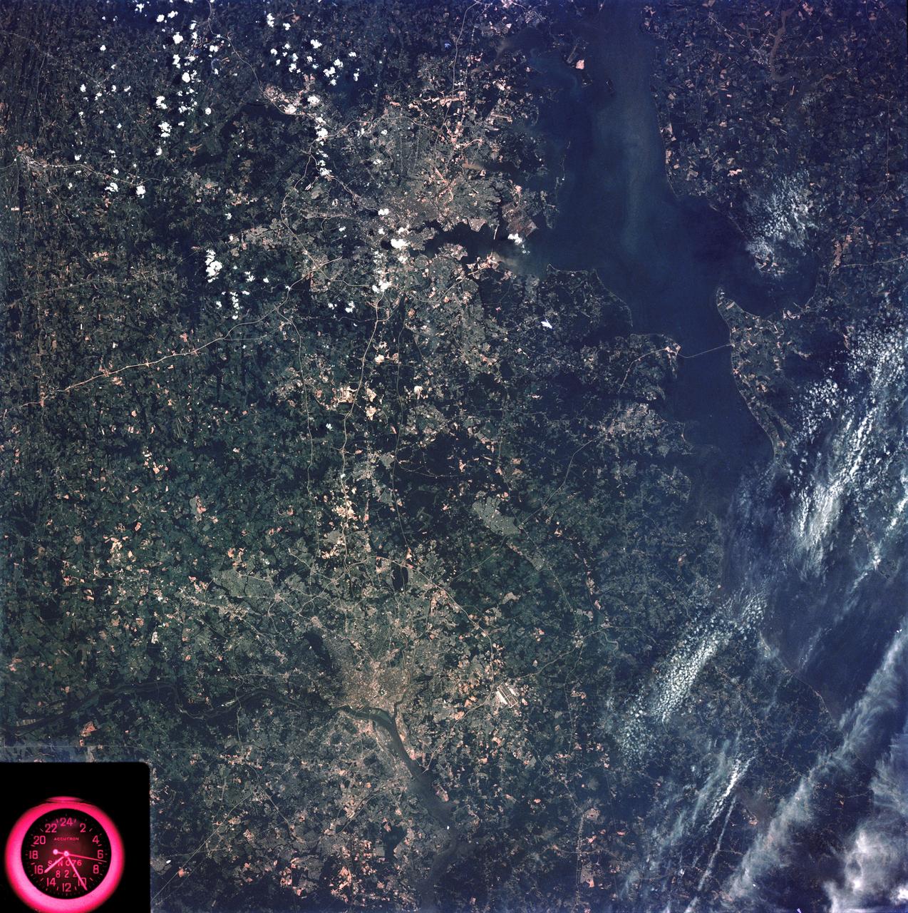
SL3-83-166 (July-September 1973) --- A vertical view of the Washington D.C. and the Baltimore, Maryland area is seen in the Skylab 3 Earth Resources Experiments Package S190-B (five-inch Earth terrain camera) photograph taken from the Skylab space station in Earth orbit. The Chesapeake Bay is on the right (east) side of the picture. The Potomac River flows through the Washington area in the lower left (southwest) corner of the photograph. Several transportation routes and major highways stand out very distinctly. Especially conspicuous are the beltways around the cities, Interstate 95 between Baltimore and the nation?s capitol and Interstate 70N leading west from Baltimore. The tunnel and harbor facilities in Baltimore show clearly, also. Identifiable features in the Washington area include the Capitol Building, the Mall area, Robert F. Kennedy Stadium (white circle), the five bridges across the Potomac, Andrews Air Force Base (on east loop), and the smaller Anacostia River. The extent of the urbanization in this area is dramatically illustrated in this picture. The photograph has sufficient resolution that the housing patterns for individual suburban areas are clearly defined with the houses shown as pink gray, wooded areas as dark green and cleared areas light green. Chesapeake Bay circulation patterns are indicated by contrast of dark and light blue. Sediment plumes (red) are seen entering the bay north and east of Baltimore. The bay bridge stands out white against the blue water. The detailed information contained in this one photograph will be of direct use to several EREP investigator teams in land use analysis, sedimentation and circulation patterns in the bay, and resource surveys of Maryland. All EREP photography is available to the public through the Department of Interior?s Earth Resources Observations Systems Data Center, Sioux Falls, South Dakota, 57198. Photo credit: NASA

Just in time for the release of the movie “Star Wars Episode VII: The Force Awakens,” NASA’s Hubble Space Telescope has photographed what looks like a cosmic, double-bladed lightsaber. In the center of the image, partially obscured by a dark, Jedi-like cloak of dust, a newborn star shoots twin jets out into space as a sort of birth announcement to the universe. “Science fiction has been an inspiration to generations of scientists and engineers, and the film series Star Wars is no exception,” said John Grunsfeld, astronaut and associate administrator for the NASA Science Mission directorate. “There is no stronger case for the motivational power of real science than the discoveries that come from the Hubble Space Telescope as it unravels the mysteries of the universe." This celestial lightsaber does not lie in a galaxy far, far away, but rather inside our home galaxy, the Milky Way. It’s inside a turbulent birthing ground for new stars known as the Orion B molecular cloud complex, located 1,350 light-years away. When stars form within giant clouds of cool molecular hydrogen, some of the surrounding material collapses under gravity to form a rotating, flattened disk encircling the newborn star. Though planets will later congeal in the disk, at this early stage the protostar is feeding on the disk with a Jabba-like appetite. Gas from the disk rains down onto the protostar and engorges it. Superheated material spills away and is shot outward from the star in opposite directions along an uncluttered escape route — the star’s rotation axis. Shock fronts develop along the jets and heat the surrounding gas to thousands of degrees Fahrenheit. The jets collide with the surrounding gas and dust and clear vast spaces, like a stream of water plowing into a hill of sand. The shock fronts form tangled, knotted clumps of nebulosity and are collectively known as Herbig-Haro (HH) objects. The prominent HH object shown in this image is HH 24. Just to the right of the cloaked star, a couple of bright points are young stars peeking through and showing off their own faint lightsabers — including one that has bored a tunnel through the cloud towards the upper-right side of the picture. Overall, just a handful of HH jets have been spotted in this region in visible light, and about the same number in the infrared. Hubble’s observations for this image were performed in infrared light, which enabled the telescope to peer through the gas and dust cocooning the newly forming stars and capture a clear view of the HH objects. These young stellar jets are ideal targets for NASA’s upcoming James Webb Space Telescope, which will have even greater infrared wavelength vision to see deeper into the dust surrounding newly forming stars. The Hubble Space Telescope is a project of international cooperation between NASA and the European Space Agency. NASA’s Goddard Space Flight Center in Greenbelt, Maryland, manages the telescope. The Space Telescope Science Institute (STScI) in Baltimore, Maryland, conducts Hubble science operations. STScI is operated for NASA by the Association of Universities for Research in Astronomy, in Washington, D.C. Credits: NASA/ESA <b><a href="http://www.nasa.gov/audience/formedia/features/MP_Photo_Guidelines.html" rel="nofollow">NASA image use policy.</a></b> <b><a href="http://www.nasa.gov/centers/goddard/home/index.html" rel="nofollow">NASA Goddard Space Flight Center</a></b> enables NASA’s mission through four scientific endeavors: Earth Science, Heliophysics, Solar System Exploration, and Astrophysics. Goddard plays a leading role in NASA’s accomplishments by contributing compelling scientific knowledge to advance the Agency’s mission. <b>Follow us on <a href="http://twitter.com/NASAGoddardPix" rel="nofollow">Twitter</a></b> <b>Like us on <a href="http://www.facebook.com/pages/Greenbelt-MD/NASA-Goddard/395013845897?ref=tsd" rel="nofollow">Facebook</a></b> <b>Find us on <a href="http://instagrid.me/nasagoddard/?vm=grid" rel="nofollow">Instagram</a></b>