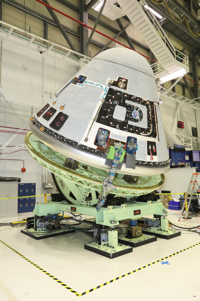
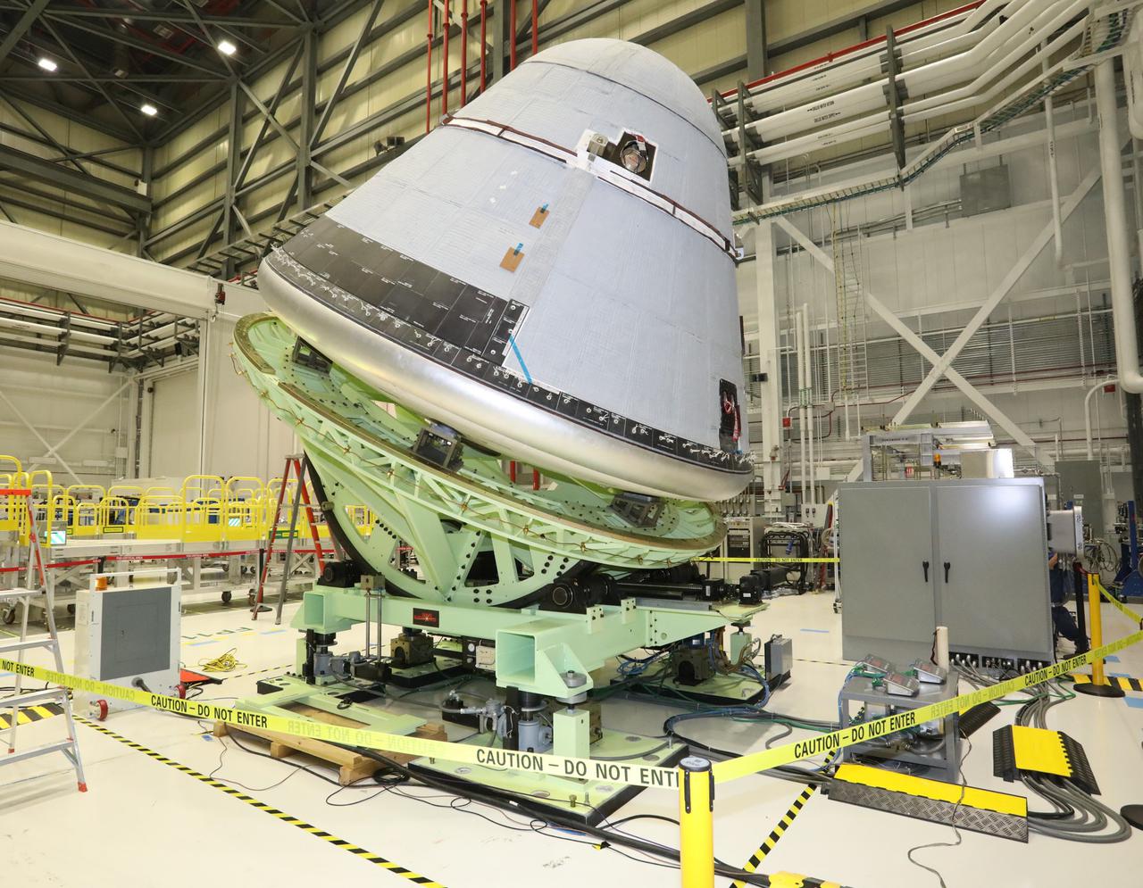
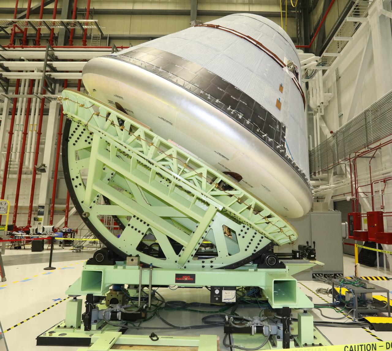
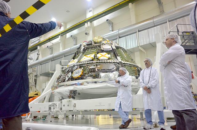
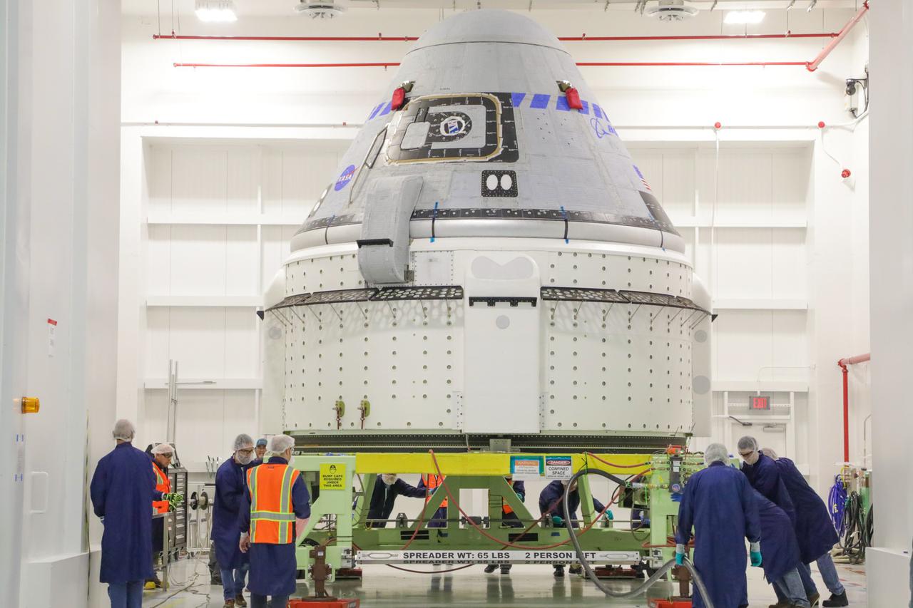
Boeing’s Starliner crew module is weighed in the Commercial Crew and Cargo Processing Facility at Kennedy Space Center in Florida on Jan. 14, 2021, in preparation for the company’s second Orbital Flight Test (OFT-2), as part of NASA’s Commercial Crew Program.. The Weight and Center of Gravity test measures the weight and balance of the spacecraft to ensure optimal performance during launch and re-entry. The test helps to validate parameters required for launching on United Launch Alliance’s Atlas V rocket, docking to the International Space Station and for navigation of the vehicle, among others.
Boeing’s Starliner crew module is weighed in the Commercial Crew and Cargo Processing Facility at Kennedy Space Center in Florida on Jan. 14, 2021, in preparation for the company’s second Orbital Flight Test (OFT-2), as part of NASA’s Commercial Crew Program.. The Weight and Center of Gravity test measures the weight and balance of the spacecraft to ensure optimal performance during launch and re-entry. The test helps to validate parameters required for launching on United Launch Alliance’s Atlas V rocket, docking to the International Space Station and for navigation of the vehicle, among others.
Boeing’s Starliner crew module is weighed in the Commercial Crew and Cargo Processing Facility at Kennedy Space Center in Florida on Jan. 14, 2021, in preparation for the company’s second Orbital Flight Test (OFT-2), as part of NASA’s Commercial Crew Program.. The Weight and Center of Gravity test measures the weight and balance of the spacecraft to ensure optimal performance during launch and re-entry. The test helps to validate parameters required for launching on United Launch Alliance’s Atlas V rocket, docking to the International Space Station and for navigation of the vehicle, among others.
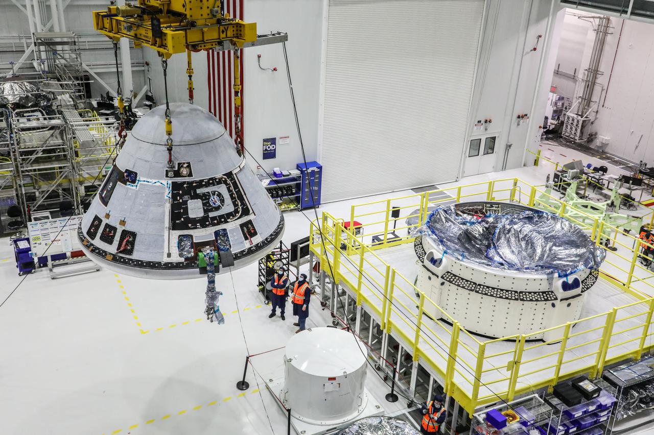
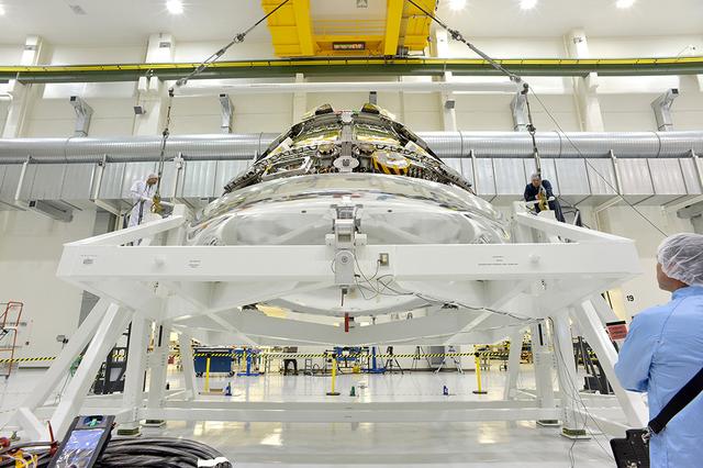
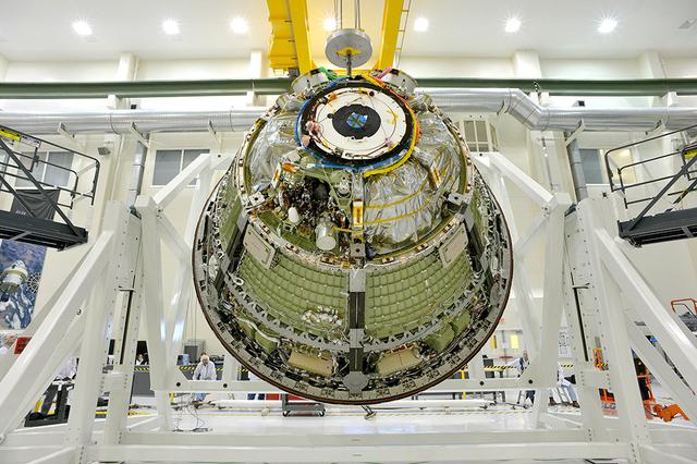
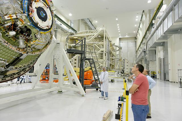
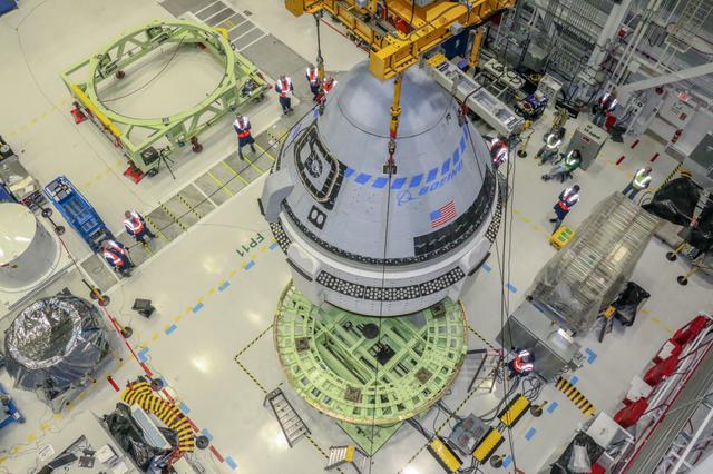
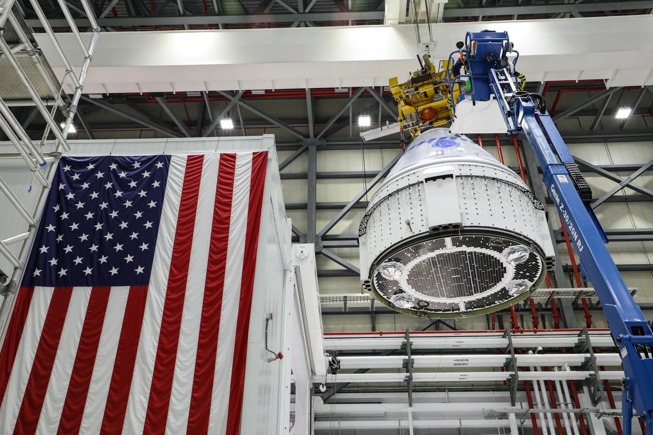
Boeing’s Starliner crew module is hoisted and moves past the service module in the Commercial Crew and Cargo Processing Facility at Kennedy Space Center in Florida on Wednesday, Jan. 13, 2021, prior to the weight and center of gravity test. The crew module and service module will soon be mated, making the spacecraft complete for the company’s second Orbital Flight Test (OFT-2) for NASA’s Commercial Crew Program. OFT-2 is a critical developmental milestone on the company’s path toward flying crew missions for NASA.
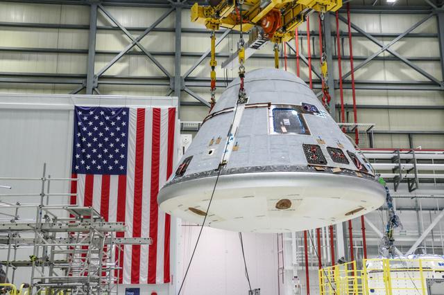
Boeing’s Starliner crew module for the company’s second Orbital Flight Test (OFT-2) is lifted Wednesday, Jan. 13, 2021, in the Commercial Crew and Cargo Processing Facility at Kennedy Space Center in Florida prior to the vehicle having a weight and center of gravity test. OFT-2 is a critical developmental milestone on the company’s path toward flying crew missions for NASA, as part of the agency’s Commercial Crew Program.
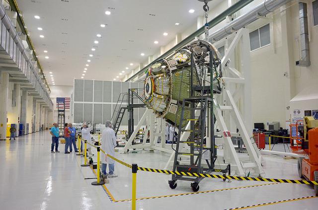
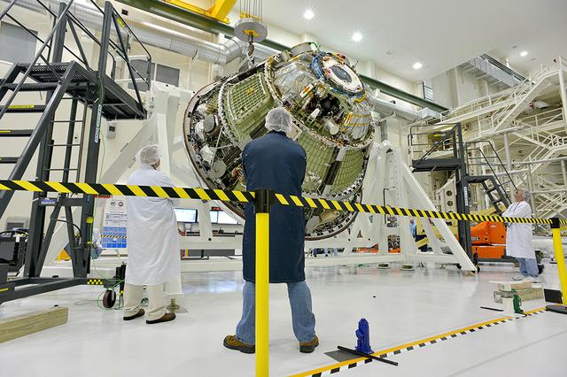
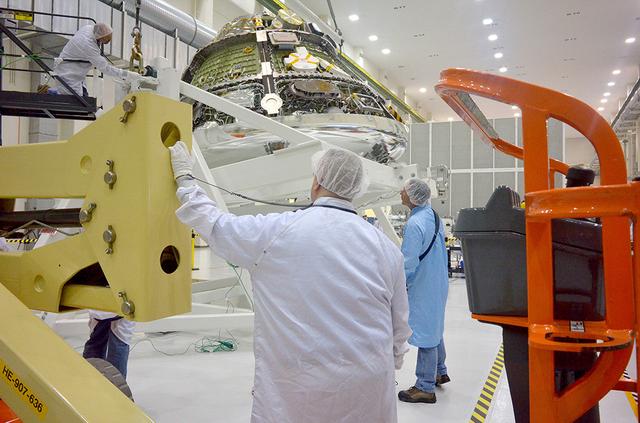
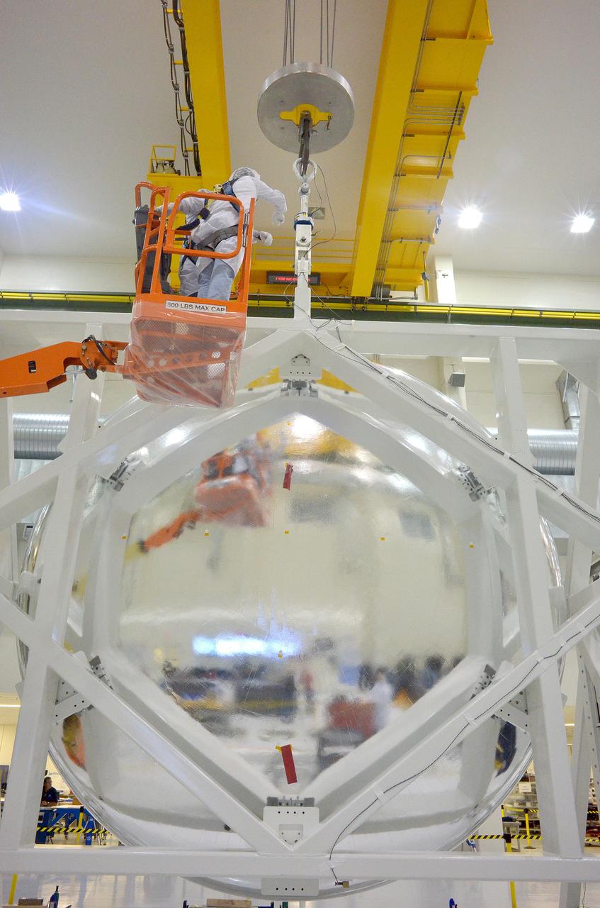
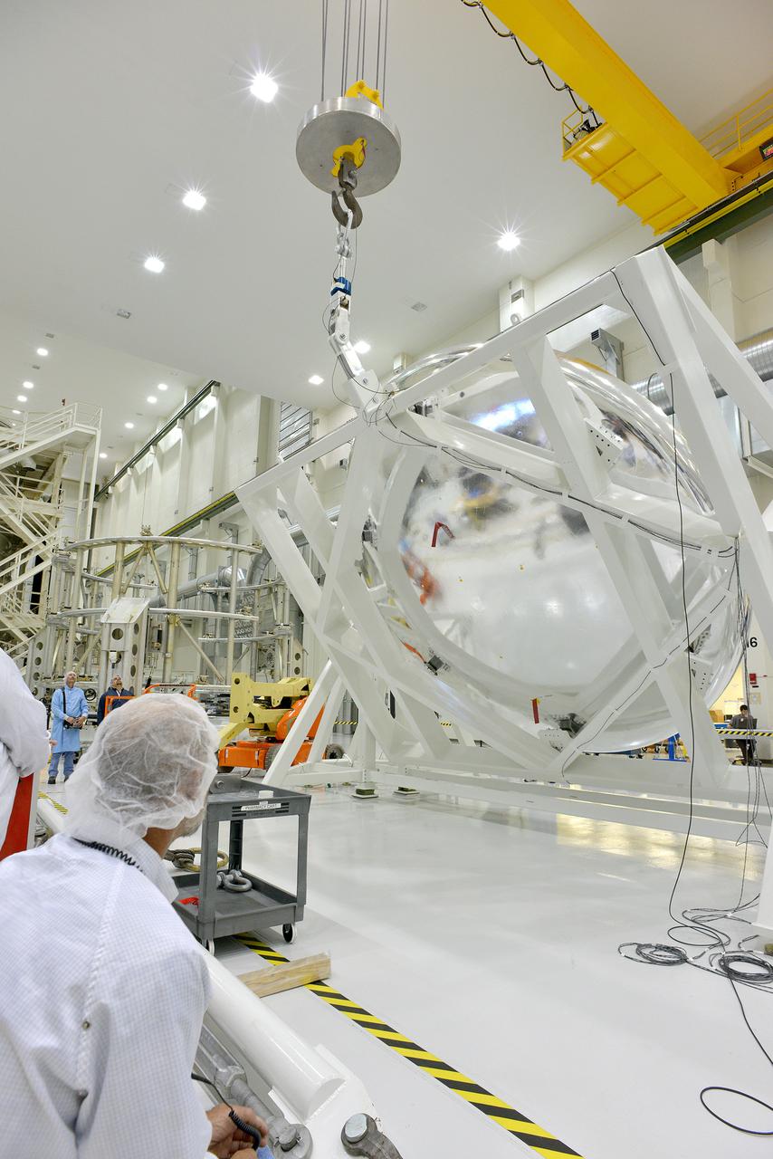
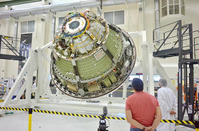
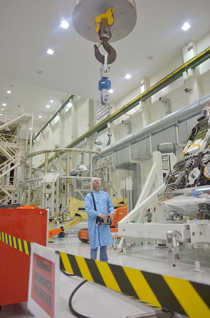
An Orion weight and center of gravity test with the Exploration Flight Test-1 (EFT-1) crew module takes place at the Operations and Checkout (O&C) Building at Kennedy Space Center on June 8, 2014. Part of Batch image transfer from Flickr.

An Orion weight and center of gravity test with the Exploration Flight Test-1 (EFT-1) crew module takes place at the Operations and Checkout (O&C) Building at Kennedy Space Center on June 8, 2014. Part of Batch image transfer from Flickr.

An Orion weight and center of gravity test with the Exploration Flight Test-1 (EFT-1) crew module takes place at the Operations and Checkout (O&C) Building at Kennedy Space Center on June 8, 2014. Part of Batch image transfer from Flickr.
An Orion weight and center of gravity test with the Exploration Flight Test-1 (EFT-1) crew module takes place at the Operations and Checkout (O&C) Building at Kennedy Space Center on June 8, 2014. Part of Batch image transfer from Flickr.

An Orion weight and center of gravity test with the Exploration Flight Test-1 (EFT-1) crew module takes place at the Operations and Checkout (O&C) Building at Kennedy Space Center on June 8, 2014. Part of Batch image transfer from Flickr.

An Orion weight and center of gravity test with the Exploration Flight Test-1 (EFT-1) crew module takes place at the Operations and Checkout (O&C) Building at Kennedy Space Center on June 8, 2014. Part of Batch image transfer from Flickr.

An Orion weight and center of gravity test with the Exploration Flight Test-1 (EFT-1) crew module takes place at the Operations and Checkout (O&C) Building at Kennedy Space Center on June 8, 2014. Part of Batch image transfer from Flickr.
An Orion weight and center of gravity test with the Exploration Flight Test-1 (EFT-1) crew module takes place at the Operations and Checkout (O&C) Building at Kennedy Space Center on June 8, 2014. Part of Batch image transfer from Flickr.

An Orion weight and center of gravity test with the Exploration Flight Test-1 (EFT-1) crew module takes place at the Operations and Checkout (O&C) Building at Kennedy Space Center on June 8, 2014. Part of Batch image transfer from Flickr.

An Orion weight and center of gravity test with the Exploration Flight Test-1 (EFT-1) crew module takes place at the Operations and Checkout (O&C) Building at Kennedy Space Center on June 8, 2014. Part of Batch image transfer from Flickr.

An Orion weight and center of gravity test with the Exploration Flight Test-1 (EFT-1) crew module takes place at the Operations and Checkout (O&C) Building at Kennedy Space Center on June 8, 2014. Part of Batch image transfer from Flickr.

An Orion weight and center of gravity test with the Exploration Flight Test-1 (EFT-1) crew module takes place at the Operations and Checkout (O&C) Building at Kennedy Space Center on June 8, 2014. Part of Batch image transfer from Flickr.

An Orion weight and center of gravity test with the Exploration Flight Test-1 (EFT-1) crew module takes place at the Operations and Checkout (O&C) Building at Kennedy Space Center on June 8, 2014. Part of Batch image transfer from Flickr.

An Orion weight and center of gravity test with the Exploration Flight Test-1 (EFT-1) crew module takes place at the Operations and Checkout (O&C) Building at Kennedy Space Center on June 8, 2014. Part of Batch image transfer from Flickr.
An Orion weight and center of gravity test with the Exploration Flight Test-1 (EFT-1) crew module takes place at the Operations and Checkout (O&C) Building at Kennedy Space Center on June 8, 2014. Part of Batch image transfer from Flickr.

An Orion weight and center of gravity test with the Exploration Flight Test-1 (EFT-1) crew module takes place at the Operations and Checkout (O&C) Building at Kennedy Space Center on June 8, 2014. Part of Batch image transfer from Flickr.
An Orion weight and center of gravity test with the Exploration Flight Test-1 (EFT-1) crew module takes place at the Operations and Checkout (O&C) Building at Kennedy Space Center on June 8, 2014. Part of Batch image transfer from Flickr.
An Orion weight and center of gravity test with the Exploration Flight Test-1 (EFT-1) crew module takes place at the Operations and Checkout (O&C) Building at Kennedy Space Center on June 8, 2014.Part of Batch image transfer from Flickr.
An Orion weight and center of gravity test with the Exploration Flight Test-1 (EFT-1) crew module takes place at the Operations and Checkout (O&C) Building at Kennedy Space Center on June 8, 2014. Part of Batch image transfer from Flickr.
An Orion weight and center of gravity test with the Exploration Flight Test-1 (EFT-1) crew module takes place at the Operations and Checkout (O&C) Building at Kennedy Space Center on June 8, 2014. Part of Batch image transfer from Flickr.
An Orion weight and center of gravity test with the Exploration Flight Test-1 (EFT-1) crew module takes place at the Operations and Checkout (O&C) Building at Kennedy Space Center on June 8, 2014. Part of Batch image transfer from Flickr.
An Orion weight and center of gravity test with the Exploration Flight Test-1 (EFT-1) crew module takes place at the Operations and Checkout (O&C) Building at Kennedy Space Center on June 8, 2014. Part of Batch image transfer from Flickr.
An Orion weight and center of gravity test with the Exploration Flight Test-1 (EFT-1) crew module takes place at the Operations and Checkout (O&C) Building at Kennedy Space Center on June 8, 2014. Part of Batch image transfer from Flickr.
An Orion weight and center of gravity test with the Exploration Flight Test-1 (EFT-1) crew module takes place at the Operations and Checkout (O&C) Building at Kennedy Space Center on June 8, 2014. Part of Batch image transfer from Flickr.
An Orion weight and center of gravity test with the Exploration Flight Test-1 (EFT-1) crew module takes place at the Operations and Checkout (O&C) Building at Kennedy Space Center on June 8, 2014. Part of Batch image transfer from Flickr.
An Orion weight and center of gravity test with the Exploration Flight Test-1 (EFT-1) crew module takes place at the Operations and Checkout (O&C) Building at Kennedy Space Center on June 8, 2014. Part of Batch image transfer from Flickr.
An Orion weight and center of gravity test with the Exploration Flight Test-1 (EFT-1) crew module takes place at the Operations and Checkout (O&C) Building at Kennedy Space Center on June 8, 2014. Part of Batch image transfer from Flickr.

This archival photo shows the Voyager Proof Test Model (in the foreground right of center) undergoing a mechanical preparation and weight center of gravity test at NASA's Jet Propulsion Laboratory, Pasadena, California, on January 12, 1977. https://photojournal.jpl.nasa.gov/catalog/PIA21476

This archival photo shows the Voyager Proof Test Model undergoing a mechanical preparation and weight center of gravity test at NASA's Jet Propulsion Laboratory, Pasadena, California, on January 12, 1977. The stack of three white cylinders seen near center is a stand-in for the spacecraft's power generators (called RTGs). Above that, a silvery canister holds the spacecraft's magnetometer in its stowed configuration. https://photojournal.jpl.nasa.gov/catalog/PIA21477

Photos of LaRC team weighting and performing Center of Gravity (CG) measurements of the Structural Test Article (STA) at NASA Langley Research Center.
Boeing’s CST-100 Starliner undergoes weight and center of gravity checks in the Commercial Crew and Cargo Processing Facility at Kennedy Space Center in Florida on July 13, 2021. The operations are in preparation for the company’s second Orbital Flight Test (OFT-2), as part of NASA’s Commercial Crew Program.
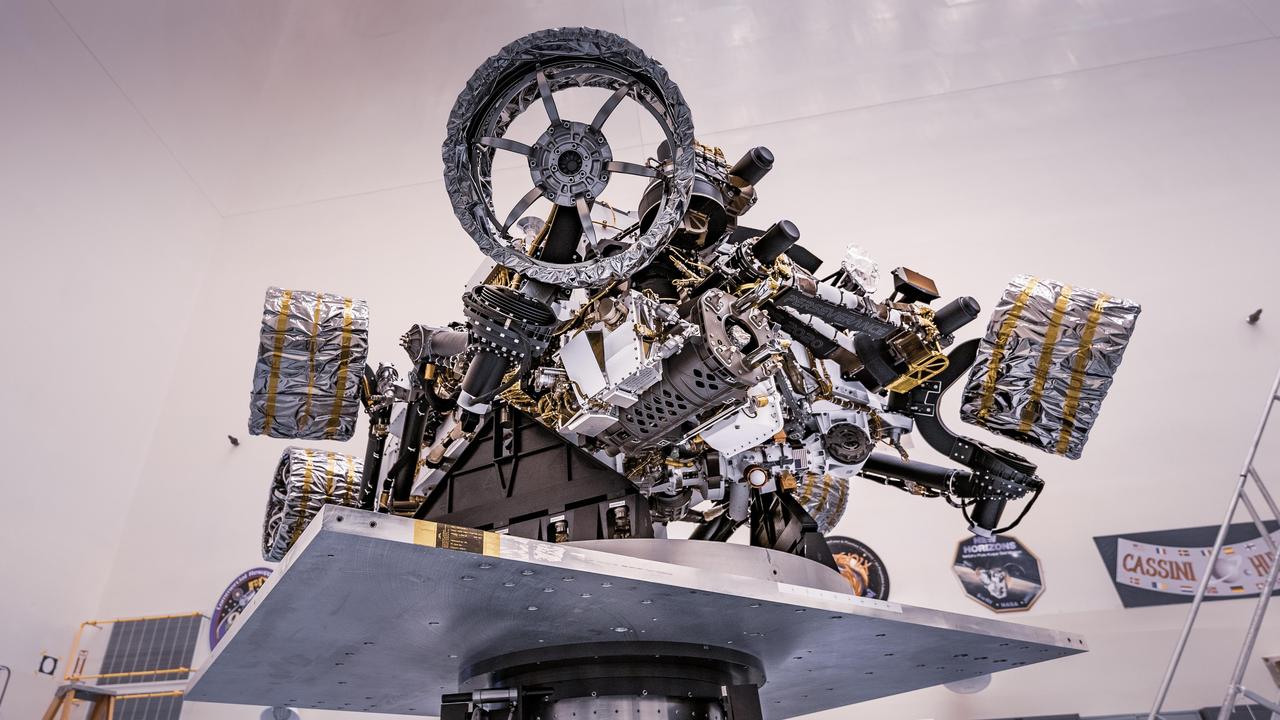
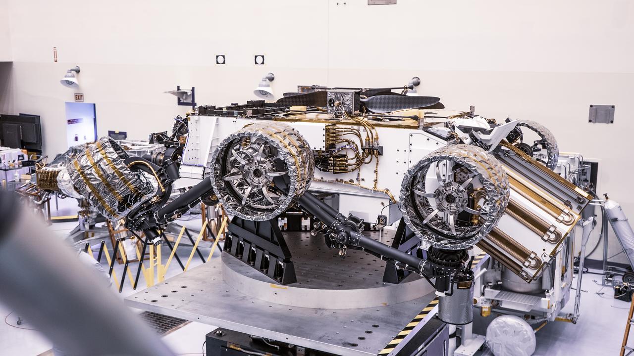
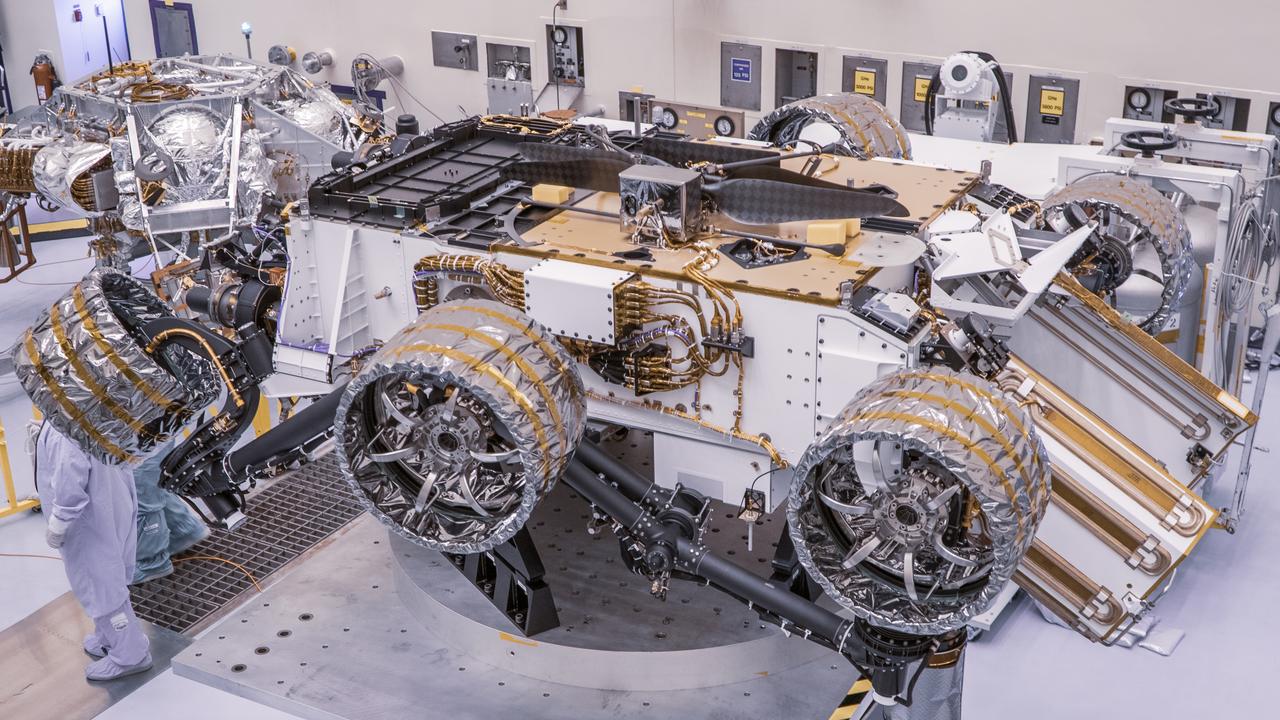
NASA's Perseverance rover can be seen attached to a spin table during a test of its mass properties at the Kennedy Space Center in Florida. During the test, the rover was rotated clockwise and counterclockwise to determine its center of gravity, or the point at which weight is evenly dispersed on all sides. The image was taken on April 7, 2020. https://photojournal.jpl.nasa.gov/catalog/PIA23826
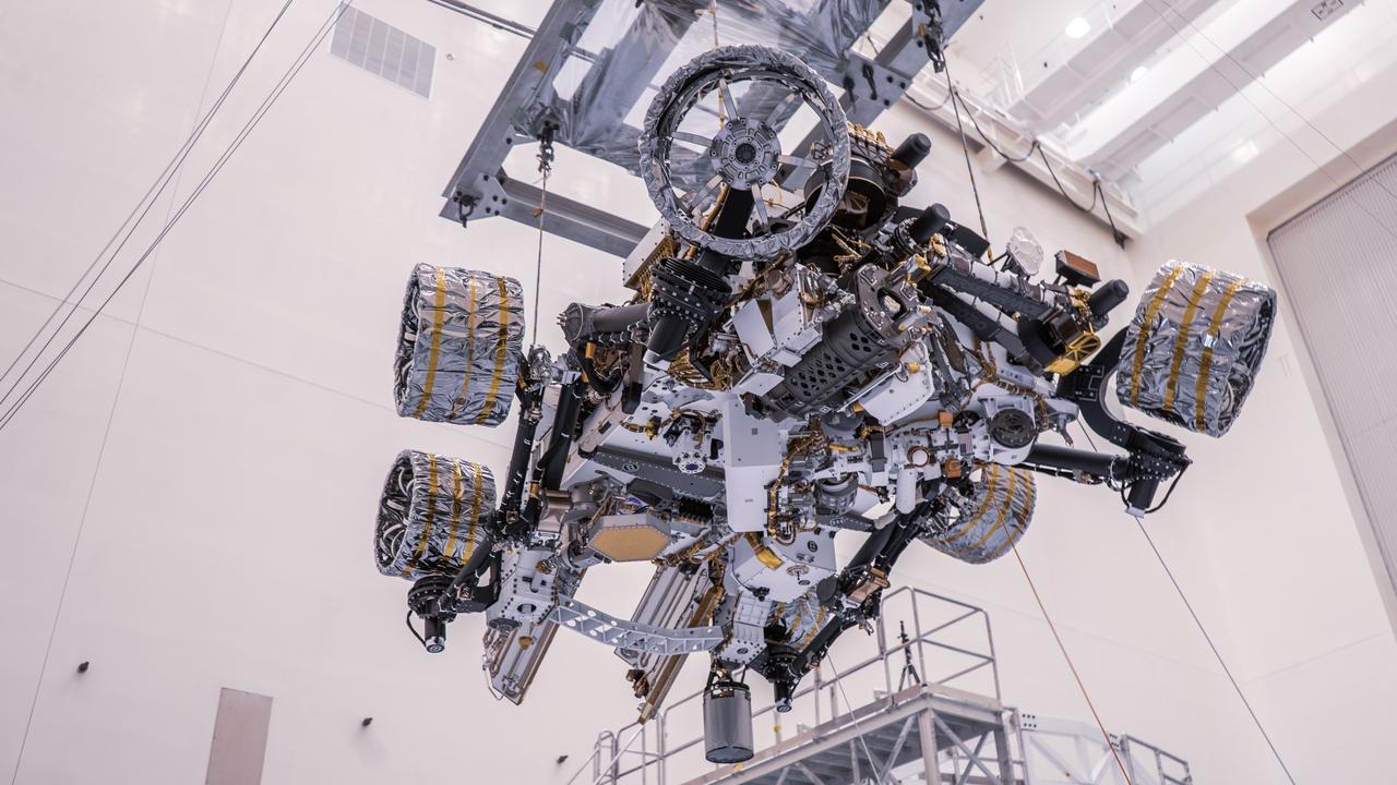
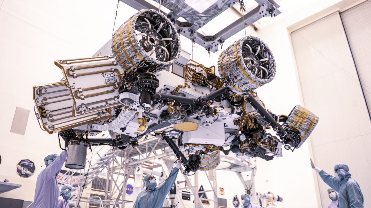
Engineers perform mass properties testing on NASA’s Mars Perseverance rover inside Kennedy Space Center’s Payload Hazardous Servicing Facility on April 7, 2020. The rover was rotated clockwise and counterclockwise on a spin table to determine the center of gravity, or the point at which weight is evenly dispersed on all sides. Establishing the rover’s center of gravity will help ensure the spacecraft will land on Mars as calculated. Perseverance will touch down on the Red Planet on Feb. 18, 2021. Liftoff aboard a United Launch Alliance Atlas V 541 rocket is targeted between July 17 and Aug. 5 from Cape Canaveral Air Force Station. NASA’s Launch Services Program based at Kennedy is managing the launch.

Engineers perform mass properties testing on NASA’s Mars Perseverance rover inside Kennedy Space Center’s Payload Hazardous Servicing Facility on April 7, 2020. The rover was rotated clockwise and counterclockwise on a spin table to determine the center of gravity, or the point at which weight is evenly dispersed on all sides. Establishing the rover’s center of gravity will help ensure the spacecraft will land on Mars as calculated. Perseverance will touch down on the Red Planet on Feb. 18, 2021. Liftoff aboard a United Launch Alliance Atlas V 541 rocket is targeted between July 17 and Aug. 5 from Cape Canaveral Air Force Station. NASA’s Launch Services Program based at Kennedy is managing the launch.
Engineers perform mass properties testing on NASA’s Mars Perseverance rover inside Kennedy Space Center’s Payload Hazardous Servicing Facility on April 7, 2020. The rover was rotated clockwise and counterclockwise on a spin table to determine the center of gravity, or the point at which weight is evenly dispersed on all sides. Establishing the rover’s center of gravity will help ensure the spacecraft will land on Mars as calculated. Perseverance will touch down on the Red Planet on Feb. 18, 2021. Liftoff aboard a United Launch Alliance Atlas V 541 rocket is targeted between July 17 and Aug. 5 from Cape Canaveral Air Force Station. NASA’s Launch Services Program based at Kennedy is managing the launch.
Engineers perform mass properties testing on NASA’s Mars Perseverance rover inside Kennedy Space Center’s Payload Hazardous Servicing Facility on April 7, 2020. The rover was rotated clockwise and counterclockwise on a spin table to determine the center of gravity, or the point at which weight is evenly dispersed on all sides. Establishing the rover’s center of gravity will help ensure the spacecraft will land on Mars as calculated. Perseverance will touch down on the Red Planet on Feb. 18, 2021. Liftoff aboard a United Launch Alliance Atlas V 541 rocket is targeted between July 17 and Aug. 5 from Cape Canaveral Air Force Station. NASA’s Launch Services Program based at Kennedy is managing the launch.
Engineers perform mass properties testing on NASA’s Mars Perseverance rover inside Kennedy Space Center’s Payload Hazardous Servicing Facility on April 7, 2020. The rover was rotated clockwise and counterclockwise on a spin table to determine the center of gravity, or the point at which weight is evenly dispersed on all sides. Establishing the rover’s center of gravity will help ensure the spacecraft will land on Mars as calculated. Perseverance will touch down on the Red Planet on Feb. 18, 2021. Liftoff aboard a United Launch Alliance Atlas V 541 rocket is targeted between July 17 and Aug. 5 from Cape Canaveral Air Force Station. NASA’s Launch Services Program based at Kennedy is managing the launch.
Engineers perform mass properties testing on NASA’s Mars Perseverance rover inside Kennedy Space Center’s Payload Hazardous Servicing Facility on April 7, 2020. The rover was rotated clockwise and counterclockwise on a spin table to determine the center of gravity, or the point at which weight is evenly dispersed on all sides. Establishing the rover’s center of gravity will help ensure the spacecraft will land on Mars as calculated. Perseverance will touch down on the Red Planet on Feb. 18, 2021. Liftoff aboard a United Launch Alliance Atlas V 541 rocket is targeted between July 17 and Aug. 5 from Cape Canaveral Air Force Station. NASA’s Launch Services Program based at Kennedy is managing the launch.

Engineers perform mass properties testing on NASA’s Mars Perseverance rover inside Kennedy Space Center’s Payload Hazardous Servicing Facility on April 7, 2020. The rover was rotated clockwise and counterclockwise on a spin table to determine the center of gravity, or the point at which weight is evenly dispersed on all sides. Establishing the rover’s center of gravity will help ensure the spacecraft will land on Mars as calculated. Perseverance will touch down on the Red Planet on Feb. 18, 2021. Liftoff aboard a United Launch Alliance Atlas V 541 rocket is targeted between July 17 and Aug. 5 from Cape Canaveral Air Force Station. NASA’s Launch Services Program based at Kennedy is managing the launch.

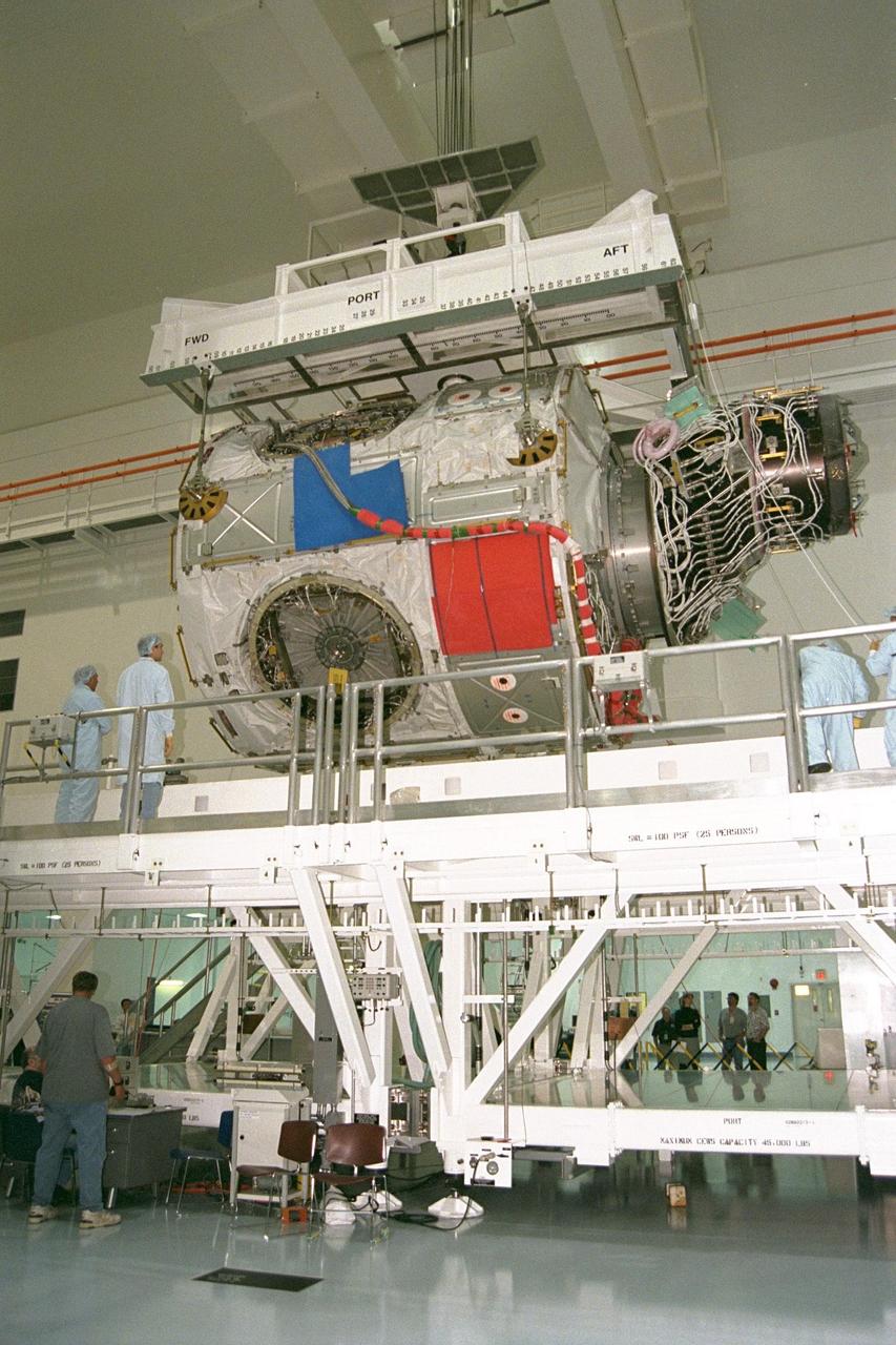
KENNEDY SPACE CENTER, FLA. -- In the Space Station Processing Facility, an overhead crane begins lifting the U.S. Lab Destiny from its test and integration stand. It will be carried to the Launch Package Integration Stand (LPIS) for a weight and center of gravity determination. Destiny is the payload aboard Space Shuttle Atlantis on mission STS-98 to the International Space Station. The lab is fitted with five system racks and will already have experiments installed inside for the flight. The launch is scheduled for January 2001
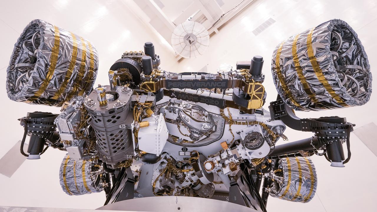
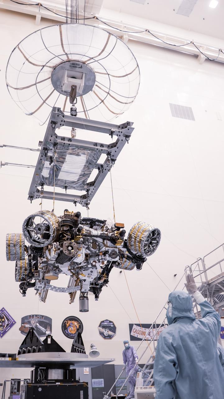
This image of the Perseverance Mars rover was taken at NASA's Kennedy Space Center on April 7, 2020, during a test of the vehicle's mass properties. The rover was rotated clockwise and counterclockwise on a spin table to determine the center of gravity, or the point at which weight is evenly dispersed on all sides. In the image, the project name "Mars 2020" and rover name "Perseverance" can be seen on name plates that have been attached to the rover's robotic arm. https://photojournal.jpl.nasa.gov/catalog/PIA23828
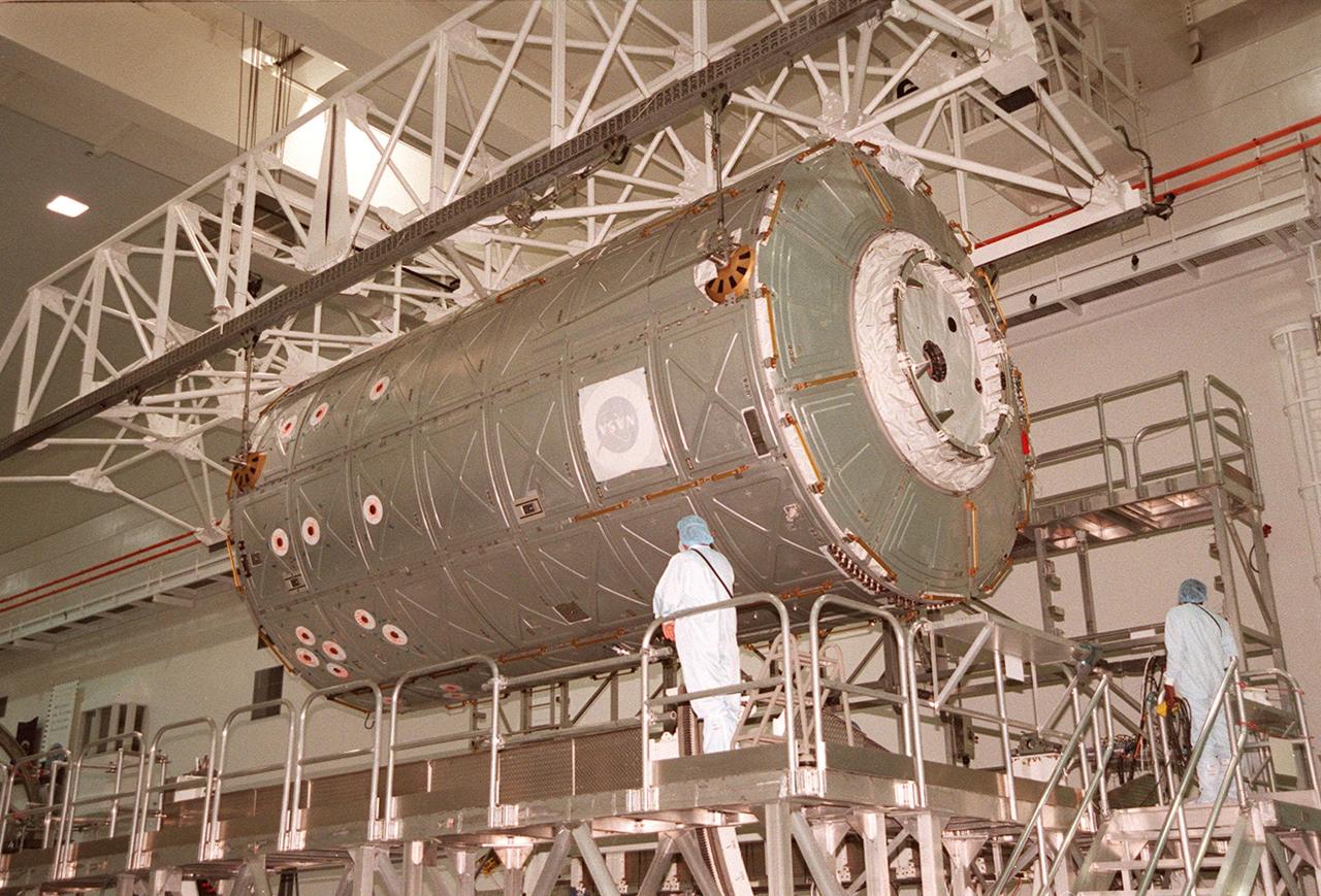
KENNEDY SPACE CENTER, FLA. -- In the Space Station Processing Facility, an overhead crane begins lifting the U.S. Lab Destiny from its test and integration stand. It will be carried to the Launch Package Integration Stand (LPIS) for a weight and center of gravity determination. Destiny is the payload aboard Space Shuttle Atlantis on mission STS-98 to the International Space Station. The lab is fitted with five system racks and will already have experiments installed inside for the flight. The launch is scheduled for January 2001

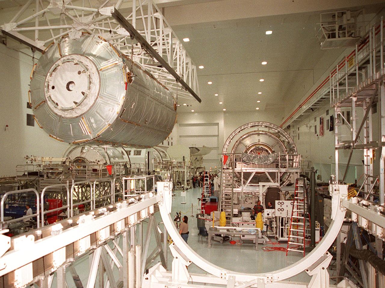
KENNEDY SPACE CENTER, FLA. -- In the Space Station Processing Facility, overhead cranes move the U.S. Lab Destiny from its test and integration stand to the Launch Package Integration Stand (LPIS) for a weight and center of gravity determination. Destiny is the payload aboard Space Shuttle Atlantis on mission STS-98 to the International Space Station. The lab is fitted with five system racks and will already have experiments installed inside for the flight. The launch is scheduled for January 2001

KENNEDY SPACE CENTER, FLA. -- In the Space Station Processing Facility, workers attach an overhead crane to the U.S. Lab Destiny. The lab is being moved from its test and integration stand to the Launch Package Integration Stand (LPIS) for a weight and center of gravity determination. Destiny is the payload aboard Space Shuttle Atlantis on mission STS-98 to the International Space Station. The lab is fitted with five system racks and will already have experiments installed inside for the flight. The launch is scheduled for January 2001
On May 3, 2022, inside the Commercial Crew and Cargo Processing Facility at Kennedy Space Center in Florida, Boeing’s CST-100 Starliner spacecraft moved from the Hazardous Processing Area to the Weight and Center of Gravity machine. The operations are in preparation for the company’s second Orbital Flight Test (OFT-2), as part of NASA’s Commercial Crew Program.

KENNEDY SPACE CENTER, FLA. -- In the Space Station Processing Facility, overhead cranes move the U.S. Lab Destiny from its test and integration stand to the Launch Package Integration Stand (LPIS) for a weight and center of gravity determination. Destiny is the payload aboard Space Shuttle Atlantis on mission STS-98 to the International Space Station. The lab is fitted with five system racks and will already have experiments installed inside for the flight. The launch is scheduled for January 2001
KENNEDY SPACE CENTER, FLA. -- In the Space Station Processing Facility, the U.S. Lab Destiny is moved from its test and integration stand to go into the Launch Package Integration Stand (LPIS) for a weight and center of gravity determination. Destiny is the payload aboard Space Shuttle Atlantis on mission STS-98 to the International Space Station. The lab is fitted with five system racks and will already have experiments installed inside for the flight. The launch is scheduled for January 2001

KENNEDY SPACE CENTER, FLA. -- In the Space Station Processing Facility, the U.S. Lab Destiny is moved from its test and integration stand to go into the Launch Package Integration Stand (LPIS) for a weight and center of gravity determination. Destiny is the payload aboard Space Shuttle Atlantis on mission STS-98 to the International Space Station. The lab is fitted with five system racks and will already have experiments installed inside for the flight. The launch is scheduled for January 2001
KENNEDY SPACE CENTER, FLA. -- In the Space Station Processing Facility, workers attach an overhead crane to the U.S. Lab Destiny. The lab is being moved from its test and integration stand to the Launch Package Integration Stand (LPIS) for a weight and center of gravity determination. Destiny is the payload aboard Space Shuttle Atlantis on mission STS-98 to the International Space Station. The lab is fitted with five system racks and will already have experiments installed inside for the flight. The launch is scheduled for January 2001
On July 13, 2021, inside the Commercial Crew and Cargo Processing Facility at Kennedy Space Center in Florida, Boeing’s CST-100 Starliner spacecraft moved from Hazardous Processing Area to the Weight and Center of Gravity machine and then transferred to the KMAG. The operations are in preparation for the company’s second Orbital Flight Test (OFT-2), as part of NASA’s Commercial Crew Program.
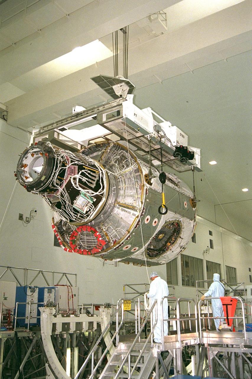
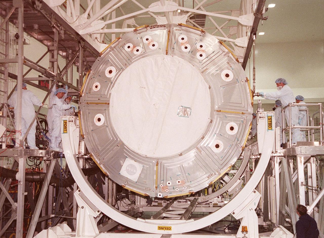
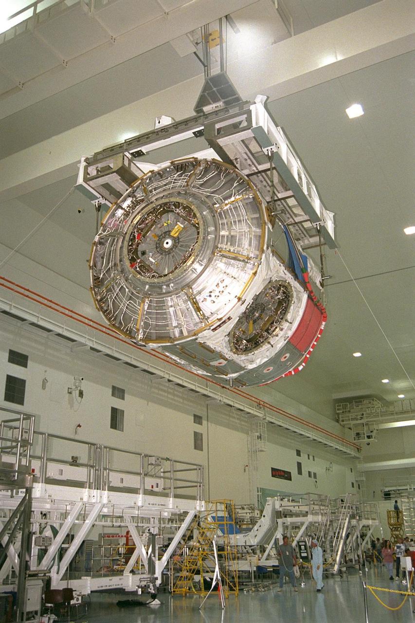
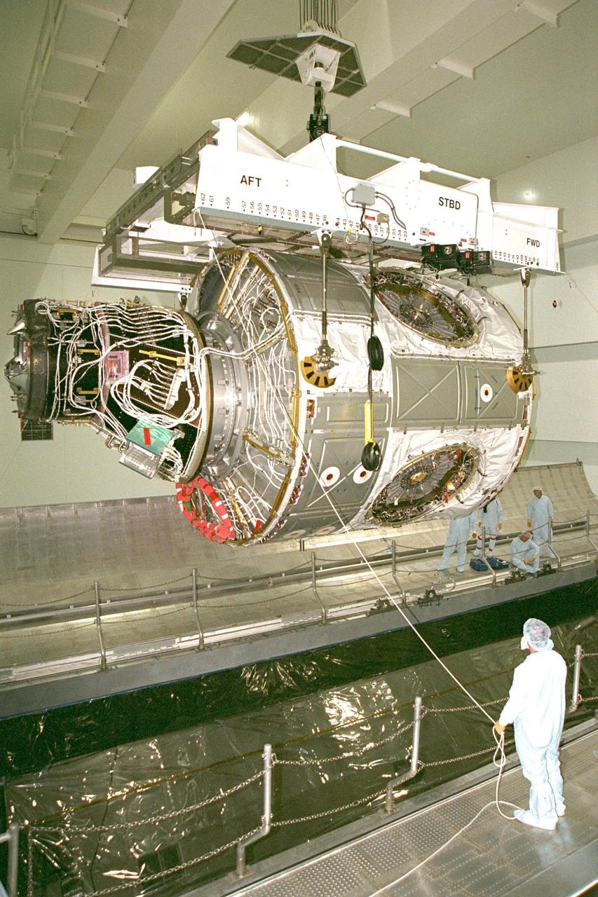
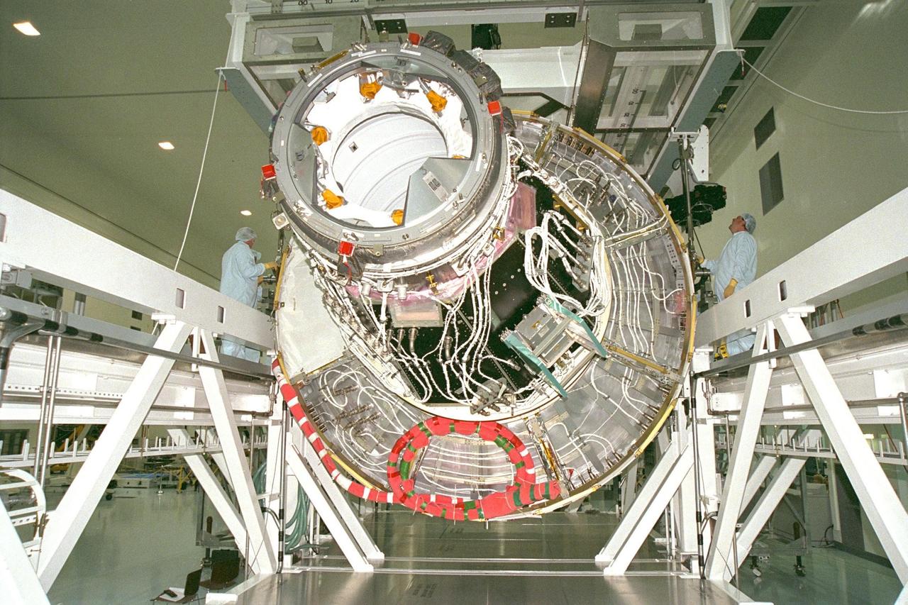
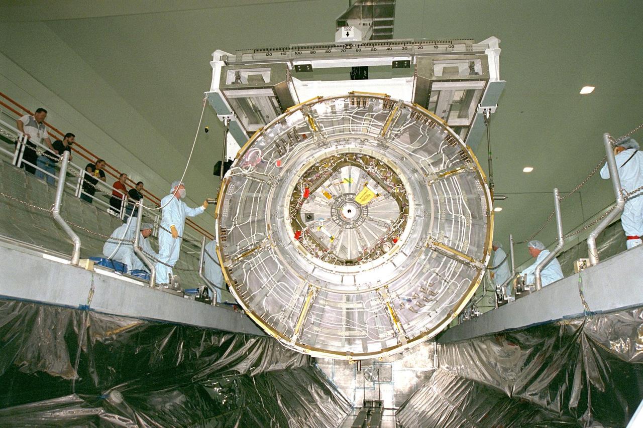
KENNEDY SPACE CENTER, FLA. -- Node 1, the first U.S. element for the International Space Station, and Pressurized Mating Adapter-1 (PMA-1) continue with prelaunch preparation activities at KSC's Space Station Processing Facility. Node 1 is a connecting passageway to the living and working areas of the space station. The node and PMA-1 are being hoisted from their workstand and moved to an element rotation stand, or test stand, where they will undergo an interim weight and center of gravity determination. The final determination is planned to be performed prior to transporting Node 1 to the launch pad. Node 1 is scheduled to fly on STS-88
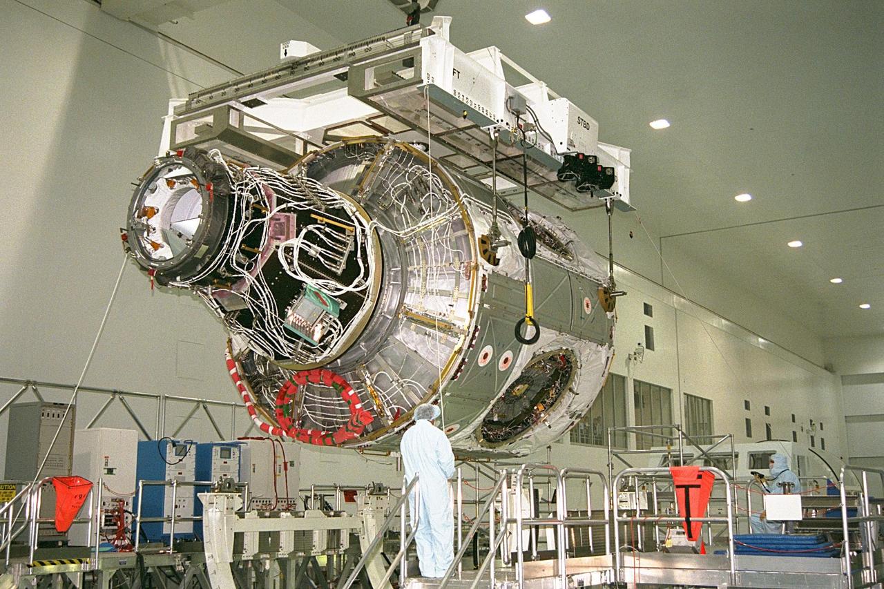
KENNEDY SPACE CENTER, FLA. -- Node 1, the first U.S. element for the International Space Station, and Pressurized Mating Adapter-1 (PMA-1) continue with prelaunch preparation activities at KSC's Space Station Processing Facility. Node 1 is a connecting passageway to the living and working areas of the space station. The node and PMA-1 are being hoisted from their workstand and moved to an element rotation stand, or test stand, where they will undergo an interim weight and center of gravity determination. The final determination is planned to be performed prior to transporting Node 1 to the launch pad. Node 1 is scheduled to fly on STS-88
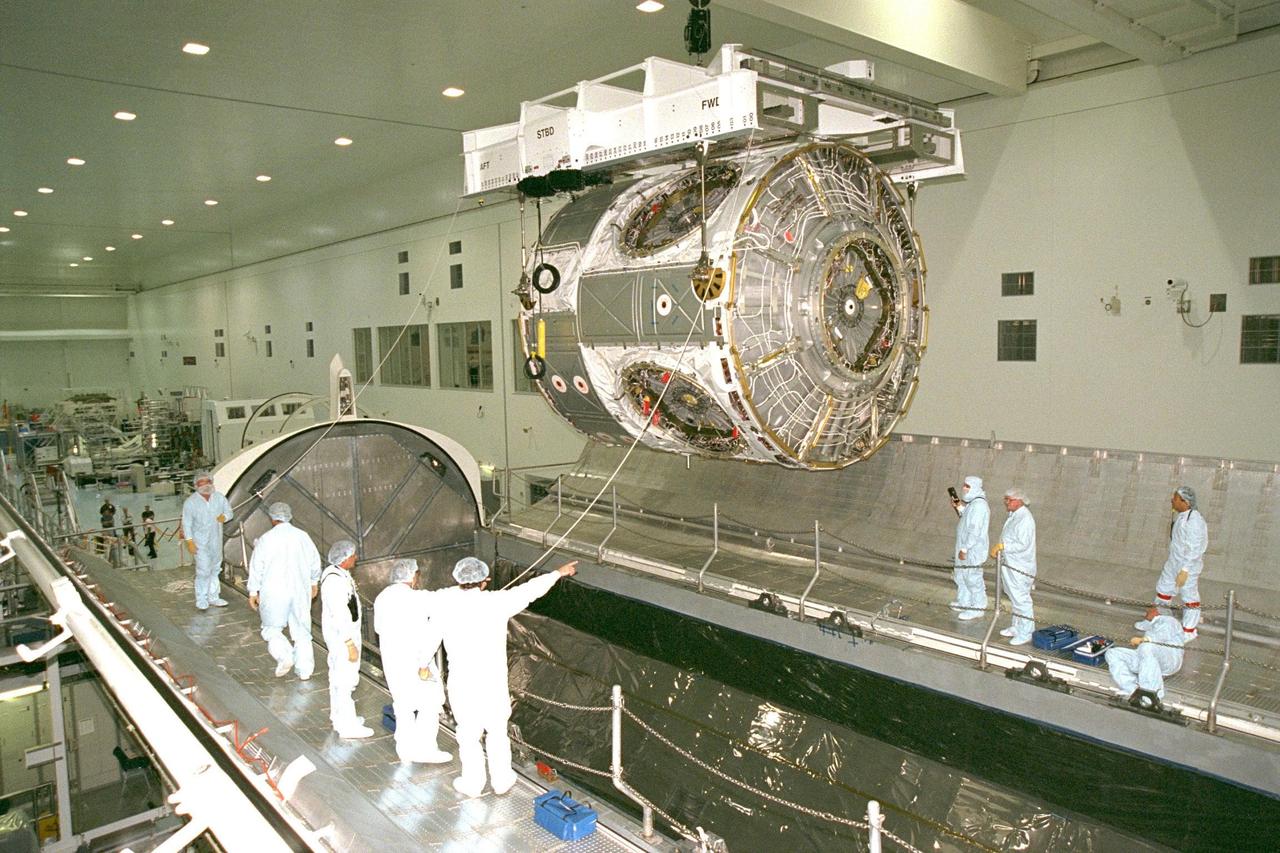
KENNEDY SPACE CENTER, FLA. -- Node 1, the first U.S. element for the International Space Station, and Pressurized Mating Adapter-1 (PMA-1) continue with prelaunch preparation activities at KSC's Space Station Processing Facility. Node 1 is a connecting passageway to the living and working areas of the space station. The node and PMA-1 are being lowered into an element rotation stand, or test stand, where they will undergo an interim weight and center of gravity determination. The final determination is planned to be performed prior to transporting Node 1 to the launch pad. Node 1 is scheduled to fly on STS-88
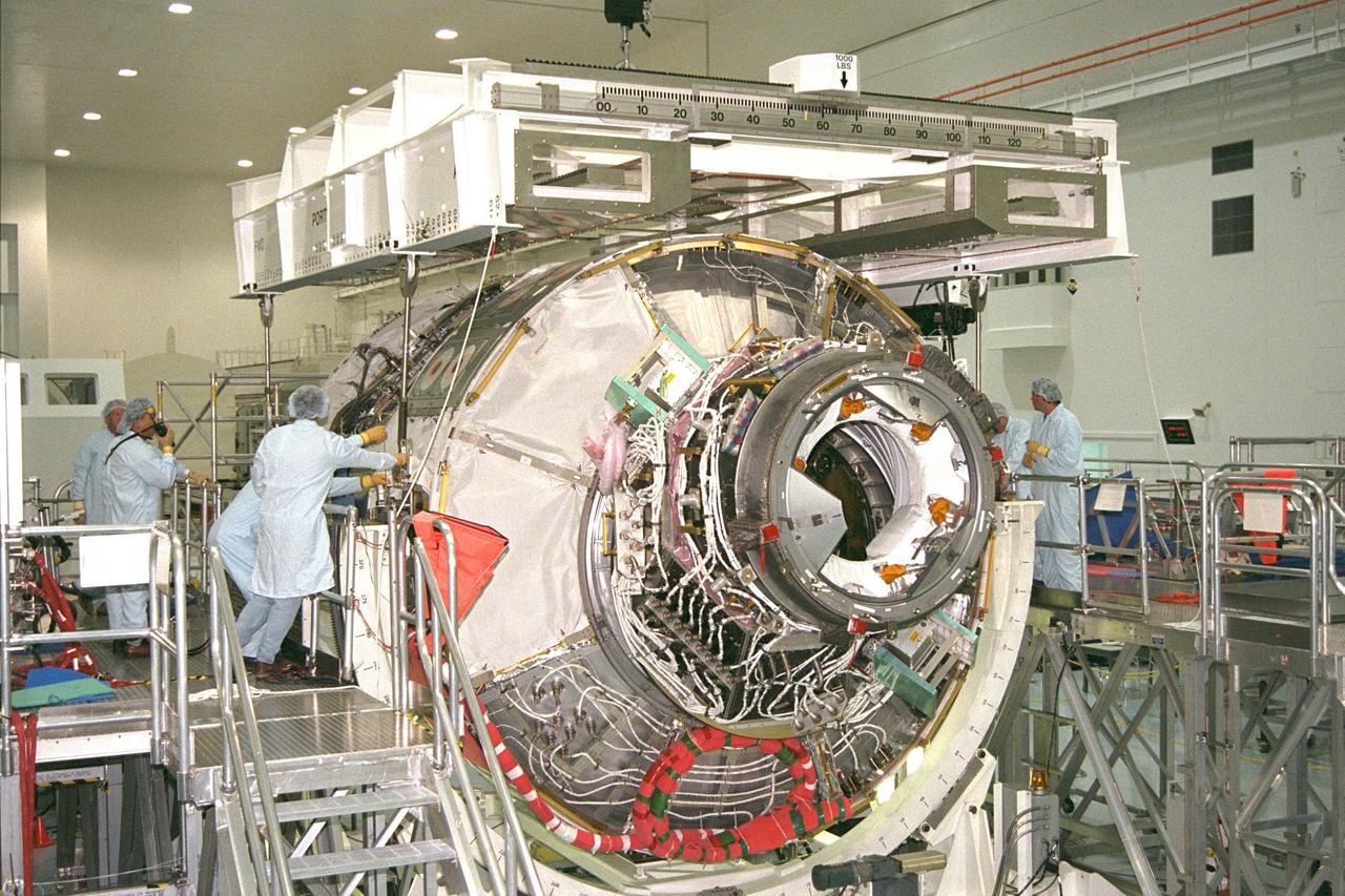
KENNEDY SPACE CENTER, FLA. -- Node 1, the first U.S. element for the International Space Station, and Pressurized Mating Adapter-1 (PMA-1) continue with prelaunch preparation activities at KSC's Space Station Processing Facility. Node 1 is a connecting passageway to the living and working areas of the space station. Boeing technicians are connecting cables to the node and PMA-1 to remove them from their workstand to an element rotation stand, or test stand, where they will undergo an interim weight and center of gravity determination. The final determination is planned to be performed prior to transporting Node 1 to the launch pad. Node 1 is scheduled to fly on STS-88
Node 1, the first U.S. element for the International Space Station, and Pressurized Mating Adapter-1 (PMA-1) continue with prelaunch preparation activities at KSC's Space Station Processing Facility. Node 1 is a connecting passageway to the living and working areas of the space station. The node and PMA-1 are being moved to an element rotation stand, or test stand, where they will undergo an interim weight and center of gravity determination. The final determination is planned to be performed prior to transporting Node 1 to the launch pad. Node 1 is scheduled to fly on STS-88
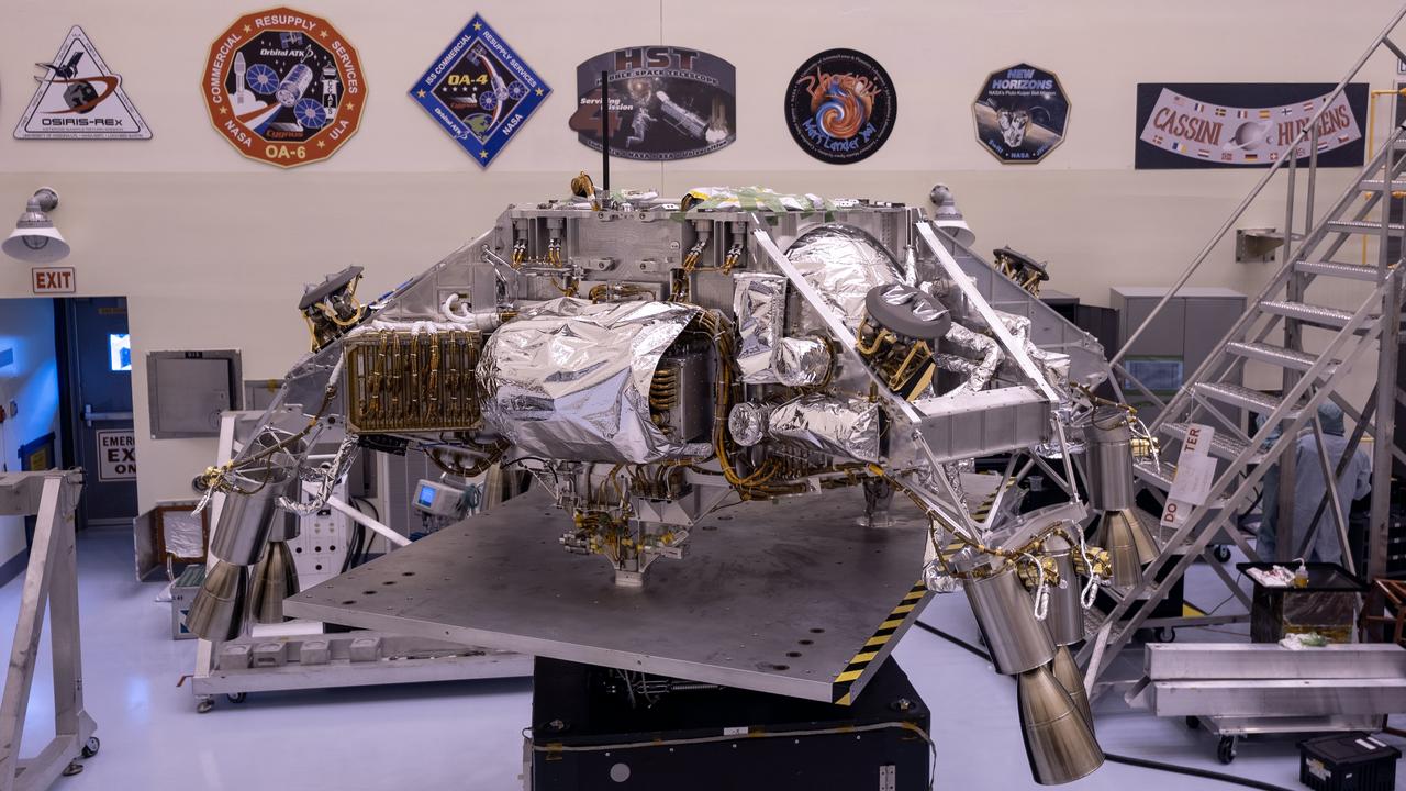
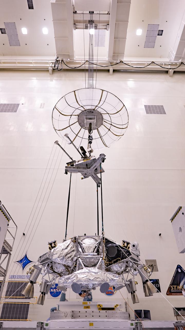
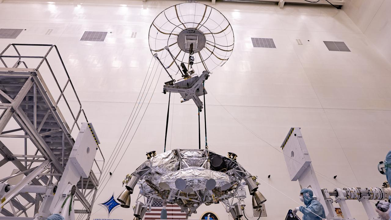
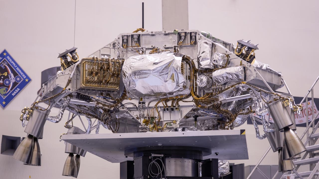
Engineers perform mass properties testing on the rocket-powered descent stage of NASA’s Mars Perseverance rover at Kennedy Space Center on April 12, 2020. The testing to determine the center of gravity, or the point at which weight is evenly dispersed on all sides, was performed inside the Florida spaceport’s Payload Hazardous Servicing Facility. The descent stage will lower the rover through the thin Martian atmosphere and onto the surface on Feb. 18, 2021. Liftoff, aboard a United Launch Alliance Atlas V 541 rocket, is targeted between July 17 and Aug. 5 from Cape Canaveral Air Force Station. NASA’s Launch Services Program based at Kennedy is managing the launch. The rover will seek signs of ancient life and collect rock and soil samples for possible return to Earth.
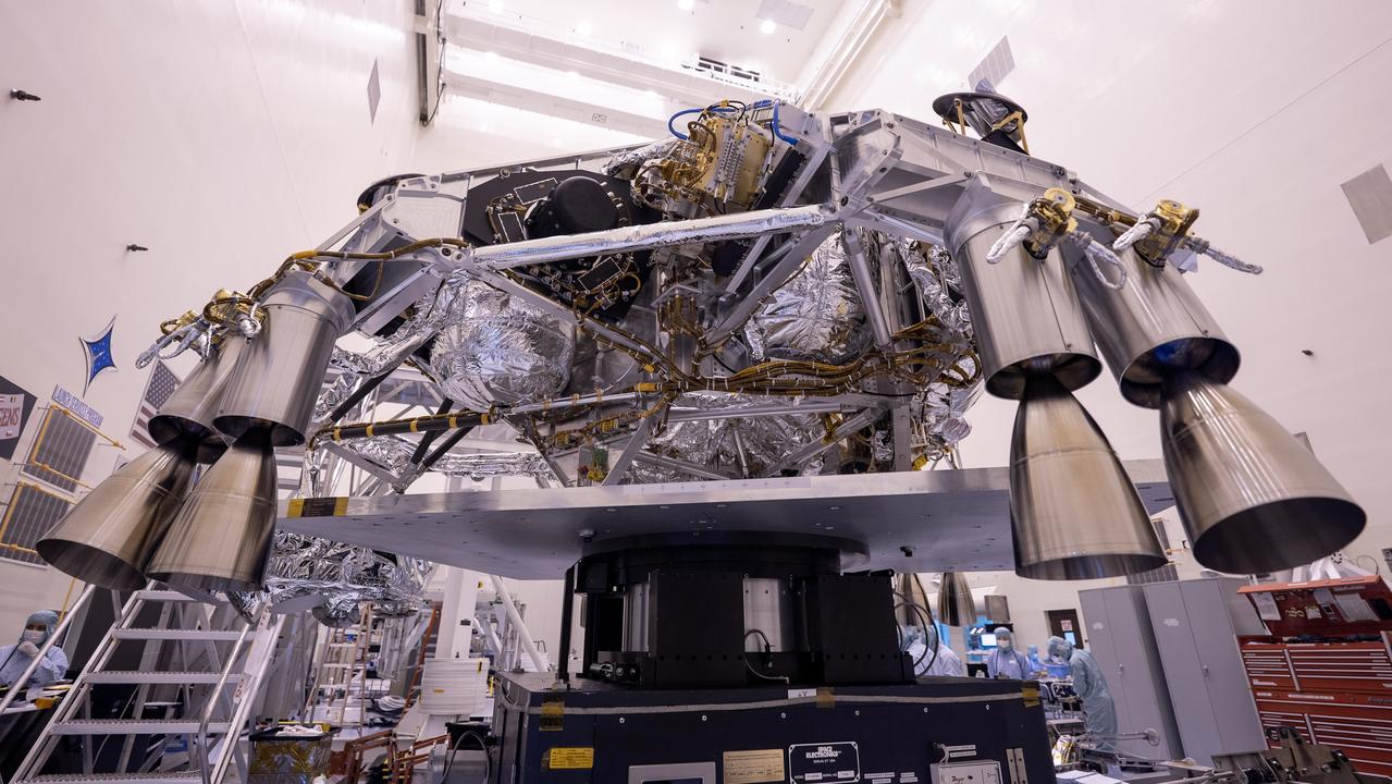
Engineers perform mass properties testing on the rocket-powered descent stage of NASA’s Mars Perseverance rover at Kennedy Space Center on April 12, 2020. The testing to determine the center of gravity, or the point at which weight is evenly dispersed on all sides, was performed inside the Florida spaceport’s Payload Hazardous Servicing Facility. The descent stage will lower the rover through the thin Martian atmosphere and onto the surface on Feb. 18, 2021. Liftoff, aboard a United Launch Alliance Atlas V 541 rocket, is targeted between July 17 and Aug. 5 from Cape Canaveral Air Force Station. NASA’s Launch Services Program based at Kennedy is managing the launch. The rover will seek signs of ancient life and collect rock and soil samples for possible return to Earth.
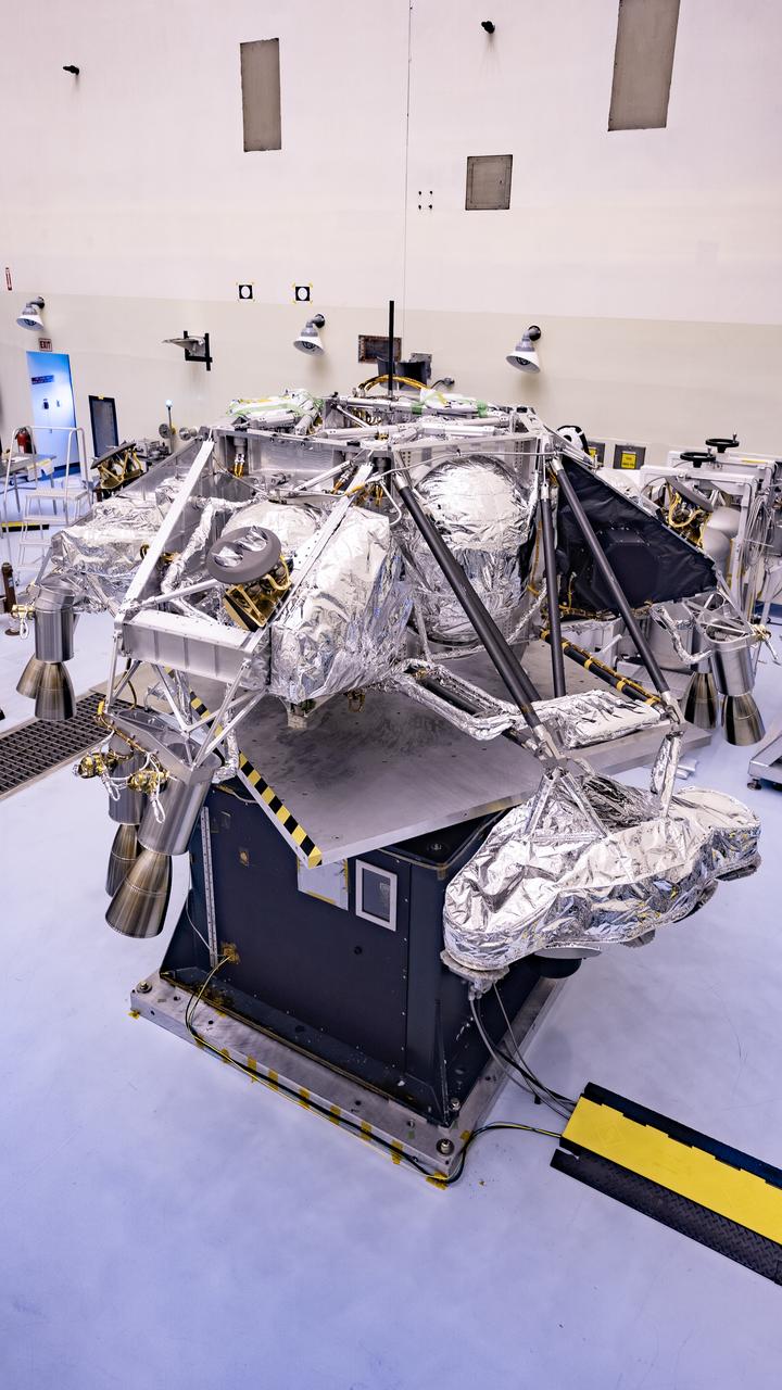
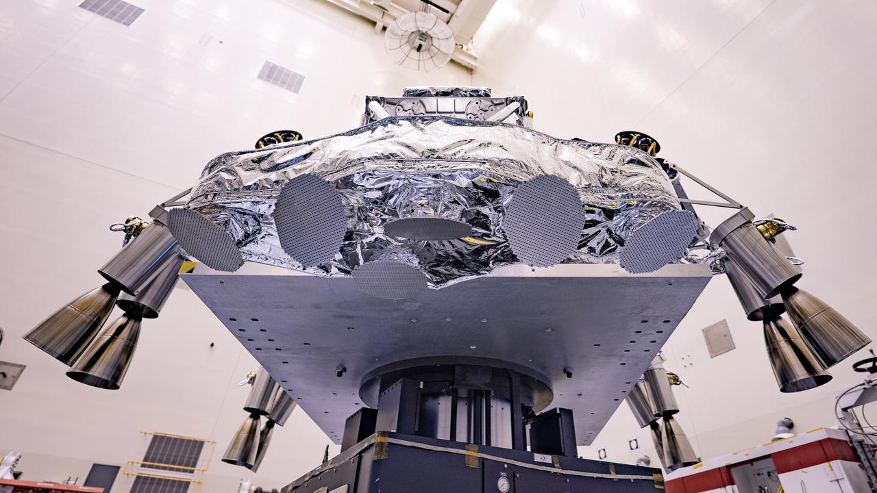
Engineers perform mass properties testing on the rocket-powered descent stage of NASA’s Mars Perseverance rover at Kennedy Space Center on April 9, 2020. The testing to determine the center of gravity, or the point at which weight is evenly dispersed on all sides, was performed inside the Florida spaceport’s Payload Hazardous Servicing Facility. The descent stage will lower the rover through the thin Martian atmosphere and onto the surface on Feb. 18, 2021. Liftoff, aboard a United Launch Alliance Atlas V 541 rocket, is targeted between July 17 and Aug. 5 from Cape Canaveral Air Force Station. NASA’s Launch Services Program based at Kennedy is managing the launch. The rover will seek signs of ancient life and collect rock and soil samples for possible return to Earth.
Engineers perform mass properties testing on the rocket-powered descent stage of NASA’s Mars Perseverance rover at Kennedy Space Center on April 12, 2020. The testing to determine the center of gravity, or the point at which weight is evenly dispersed on all sides, was performed inside the Florida spaceport’s Payload Hazardous Servicing Facility. The descent stage will lower the rover through the thin Martian atmosphere and onto the surface on Feb. 18, 2021. Liftoff, aboard a United Launch Alliance Atlas V 541 rocket, is targeted between July 17 and Aug. 5 from Cape Canaveral Air Force Station. NASA’s Launch Services Program based at Kennedy is managing the launch. The rover will seek signs of ancient life and collect rock and soil samples for possible return to Earth.
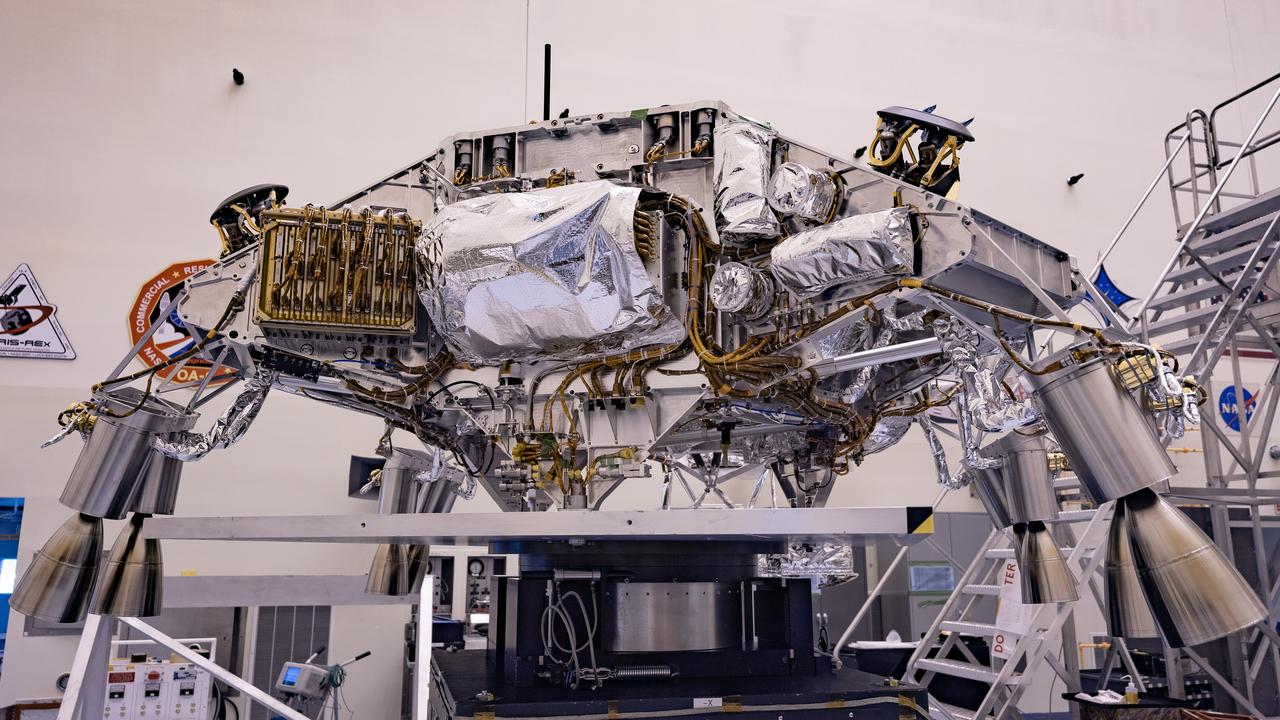
Engineers perform mass properties testing on the rocket-powered descent stage of NASA’s Mars Perseverance rover at Kennedy Space Center on April 12, 2020. The testing to determine the center of gravity, or the point at which weight is evenly dispersed on all sides, was performed inside the Florida spaceport’s Payload Hazardous Servicing Facility. The descent stage will lower the rover through the thin Martian atmosphere and onto the surface on Feb. 18, 2021. Liftoff, aboard a United Launch Alliance Atlas V 541 rocket, is targeted between July 17 and Aug. 5 from Cape Canaveral Air Force Station. NASA’s Launch Services Program based at Kennedy is managing the launch. The rover will seek signs of ancient life and collect rock and soil samples for possible return to Earth.
Engineers perform mass properties testing on the rocket-powered descent stage of NASA’s Mars Perseverance rover at Kennedy Space Center on April 9, 2020. The testing to determine the center of gravity, or the point at which weight is evenly dispersed on all sides, was performed inside the Florida spaceport’s Payload Hazardous Servicing Facility. The descent stage will lower the rover through the thin Martian atmosphere and onto the surface on Feb. 18, 2021. Liftoff, aboard a United Launch Alliance Atlas V 541 rocket, is targeted between July 17 and Aug. 5 from Cape Canaveral Air Force Station. NASA’s Launch Services Program based at Kennedy is managing the launch. The rover will seek signs of ancient life and collect rock and soil samples for possible return to Earth.
Engineers perform mass properties testing on the rocket-powered descent stage of NASA’s Mars Perseverance rover at Kennedy Space Center on April 12, 2020. The testing to determine the center of gravity, or the point at which weight is evenly dispersed on all sides, was performed inside the Florida spaceport’s Payload Hazardous Servicing Facility. The descent stage will lower the rover through the thin Martian atmosphere and onto the surface on Feb. 18, 2021. Liftoff, aboard a United Launch Alliance Atlas V 541 rocket, is targeted between July 17 and Aug. 5 from Cape Canaveral Air Force Station. NASA’s Launch Services Program based at Kennedy is managing the launch. The rover will seek signs of ancient life and collect rock and soil samples for possible return to Earth.
Engineers perform mass properties testing on the rocket-powered descent stage of NASA’s Mars Perseverance rover at Kennedy Space Center on April 12, 2020. The testing to determine the center of gravity, or the point at which weight is evenly dispersed on all sides, was performed inside the Florida spaceport’s Payload Hazardous Servicing Facility. The descent stage will lower the rover through the thin Martian atmosphere and onto the surface on Feb. 18, 2021. Liftoff, aboard a United Launch Alliance Atlas V 541 rocket, is targeted between July 17 and Aug. 5 from Cape Canaveral Air Force Station. NASA’s Launch Services Program based at Kennedy is managing the launch. The rover will seek signs of ancient life and collect rock and soil samples for possible return to Earth.
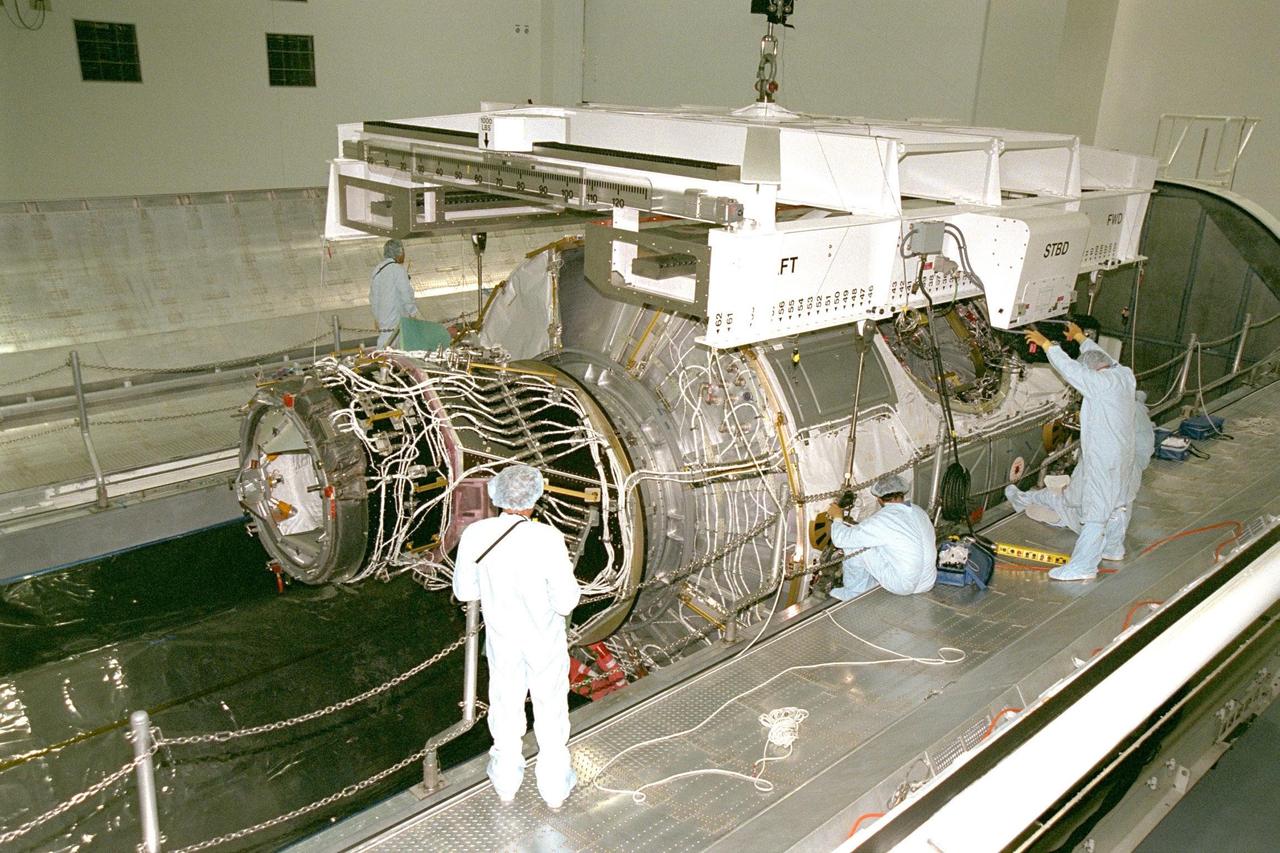
KENNEDY SPACE CENTER, FLA. -- Node 1, the first U.S. element for the International Space Station, and attached Pressurized Mating Adapter-1 (PMA-1) continue with prelaunch preparation activities at KSC's Space Station Processing Facility. Node 1 is a connecting passageway to the living and working areas of the space station. The node and PMA-1 are seen here being moved into the Shuttle payload transportation canister, where the doors will be closed for a two-week leak check. The node and PMA were moved to the canister from the element rotation stand, or test stand, where they underwent an interim weight and center of gravity determination. The final determination is planned to be performed prior to transporting Node 1 to the launch pad. Node 1 is scheduled to fly on STS-88
KENNEDY SPACE CENTER, FLA. -- Node 1, the first U.S. element for the International Space Station, and attached Pressurized Mating Adapter-1 (PMA-1) continue with prelaunch preparation activities at KSC's Space Station Processing Facility. Node 1 is a connecting passageway to the living and working areas of the space station. The node is seen here being moved into the Shuttle payload transportation canister, where the doors will be closed for a two-week leak check. The node and PMA-1 were moved to the canister from the element rotation stand, or test stand, where they underwent an interim weight and center of gravity determination. The final determination is planned to be performed prior to transporting Node 1 to the launch pad. Node 1 is scheduled to fly on STS-88
KENNEDY SPACE CENTER, FLA. -- Node 1, the first U.S. element for the International Space Station, and attached Pressurized Mating Adapter-1 continue with prelaunch preparation activities at KSC's Space Station Processing Facility. Node 1 is a connecting passageway to the living and working areas of the space station. The node and PMA-1 are being removed from the element rotation stand, or test stand, where they underwent an interim weight and center of gravity determination. (The final determination is planned to be performed prior to transporting Node 1 to the launch pad.) Now the node is being moved to the Shuttle payload transportation canister, where the doors will be closed for a two-week leak check. Node 1 is scheduled to fly on STS-88

KENNEDY SPACE CENTER, FLA. -- Node 1, the first U.S. element for the International Space Station, and attached Pressurized Mating Adapter-1 (PMA-1) continue with prelaunch preparation activities at KSC's Space Station Processing Facility. Node 1 is a connecting passageway to the living and working areas of the space station. The node and PMA-1 are being removed from the element rotation stand, or test stand, where they underwent an interim weight and center of gravity determination. (The final determination is planned to be performed prior to transporting Node 1 to the launch pad.) Now the node is being moved to the Shuttle payload transportation canister, where the doors will be closed for a two-week leak check. PMAs -2 and -3 can be seen against the right wall, with PMA-3 at the far right. Node 1 is scheduled to fly on STS-88
KENNEDY SPACE CENTER, FLA. -- Node 1, the first U.S. element for the International Space Station, and attached Pressurized Mating Adapter-1 (PMA-1) continue with prelaunch preparation activities at KSC's Space Station Processing Facility. Node 1 is a connecting passageway to the living and working areas of the space station. The node and PMA-1 are seen here being moved into the Shuttle payload transportation canister, where the doors will be closed for a two-week leak check. The node and PMA were moved to the canister from the element rotation stand, or test stand, where they underwent an interim weight and center of gravity determination. The final determination is planned to be performed prior to transporting Node 1 to the launch pad. Node 1 is scheduled to fly on STS-88
Node 1, the first U.S. element for the International Space Station, and attached Pressurized Mating Adapter-1 (PMA-1) continue with prelaunch preparation activities at KSC's Space Station Processing Facility. Node 1 is a connecting passageway to the living and working areas of the space station. The node and PMA-1 are seen here being moved into the Shuttle payload transportation canister, where the doors will be closed for a two-week leak check. The node and PMA were moved to the canister from the element rotation stand, or test stand, where they underwent an interim weight and center of gravity determination. The final determination is planned to be performed prior to transporting Node 1 to the launch pad. Node 1 is scheduled to fly on STS-88
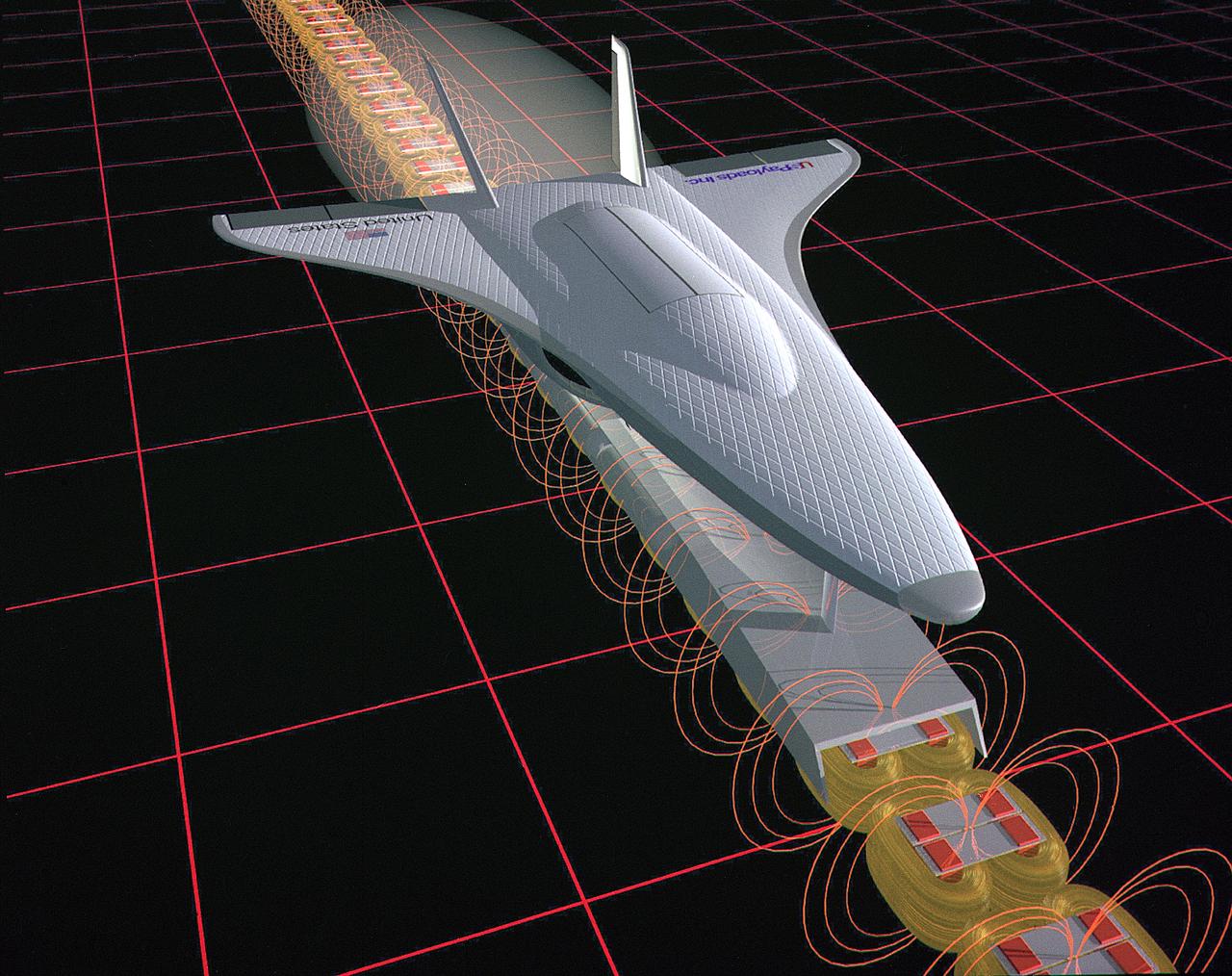
This illustration is an artist’s concept of a Magnetic Launch Assist System, formerly referred as the Magnetic Levitation (Maglev) system, for space launch. Overcoming the grip of Earth’s gravity is a supreme challenge for engineers who design rockets that leave the planet. Engineers at the Marshall Space Flight Center have developed and tested Magnetic Launch Assist System technologies that could levitate and accelerate a launch vehicle along a track at high speeds before it leaves the ground. Using electricity and magnetic fields, a Magnetic Launch Assist system would drive a spacecraft along a horizontal track until it reaches desired speeds. A full-scale, operational track would be about 1.5-miles long and capable of accelerating a vehicle to 600 mph in 9.5 seconds. The major advantages of launch assist for NASA launch vehicles is that it reduces the weight of the take-off, landing gear and the wing size, as well as the elimination of propellant weight resulting in significant cost savings. The US Navy and the British MOD (Ministry of Defense) are planning to use magnetic launch assist for their next generation aircraft carriers as the aircraft launch system. The US Army is considering using this technology for launching target drones for anti-aircraft training.
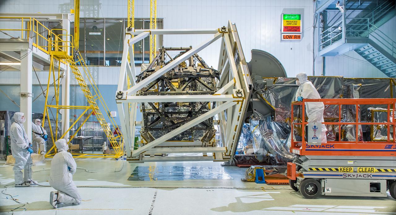
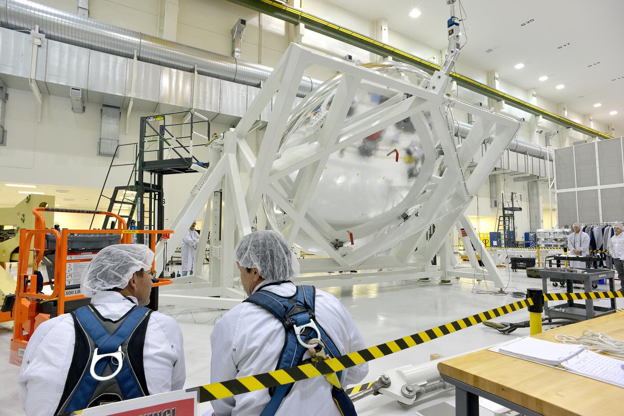
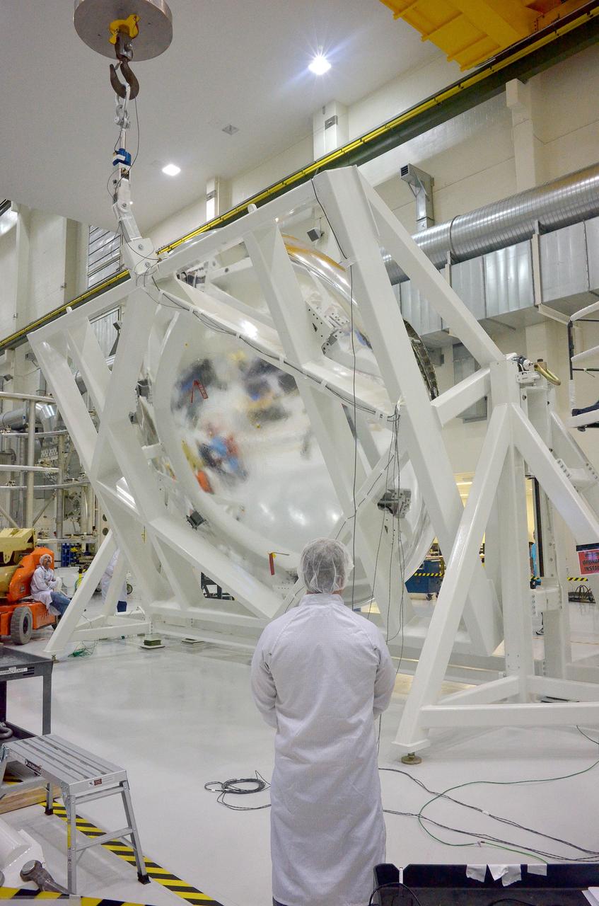
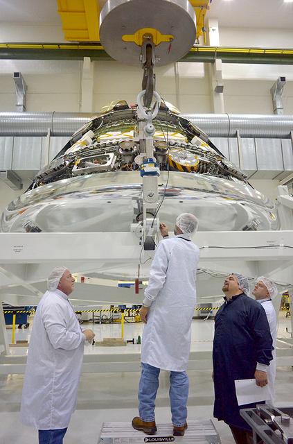
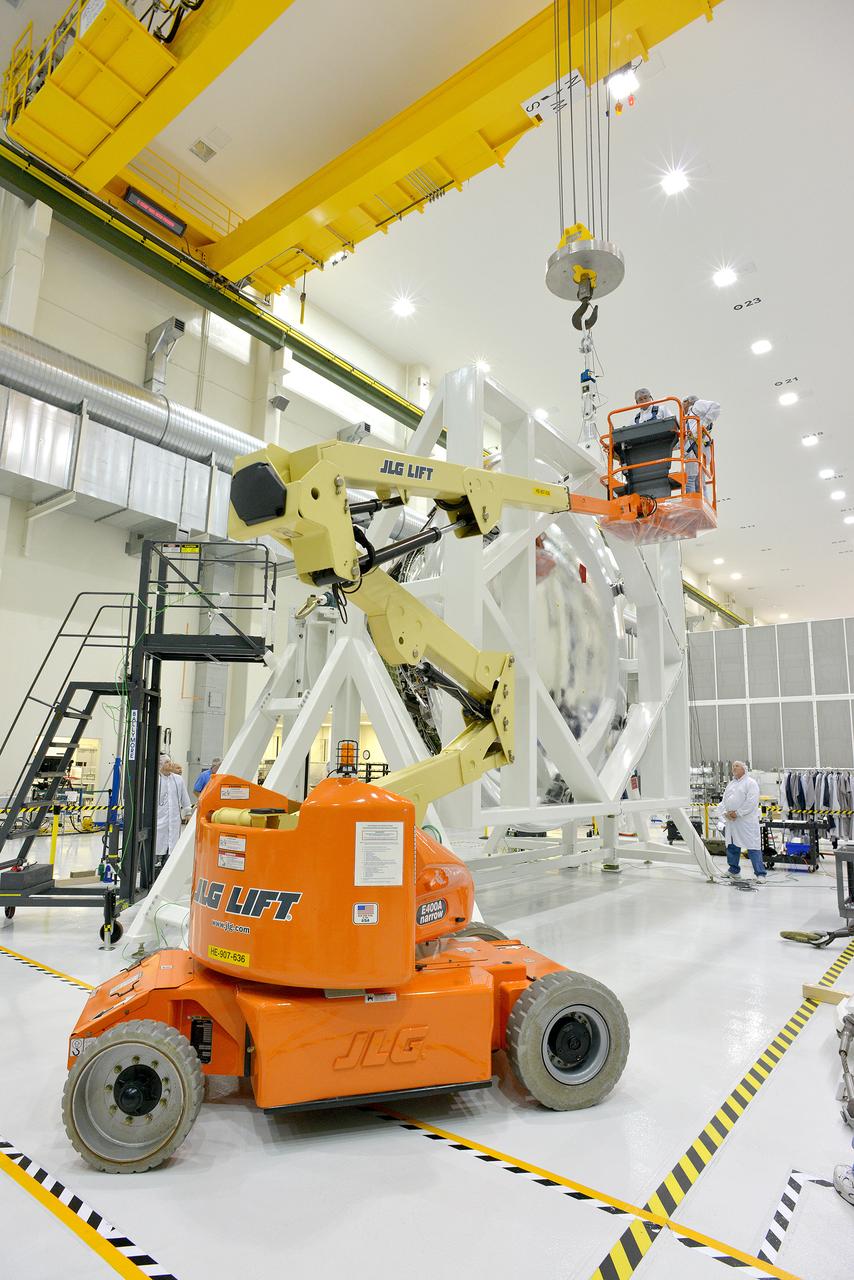
The James Webb Space Telescope's ISIM structure recently endured a "gravity sag test" as it was rotated in what looked like giant cube in a NASA clean room. The Integrated Science Instrument Module (ISIM) that will fly on the Webb telescope was rotated upside down inside a cube-like structure in the cleanroom at NASA's Goddard Space Flight Center in Greenbelt, Maryland. The purpose of "cubing" the ISIM was to test it for "gravity sag," which is to see how much the structure changes under its own weight due to gravity. The Integrated Science Instrument Module (ISIM) is one of three major elements that comprise the Webb Observatory flight system. The others are the Optical Telescope Element (OTE) and the Spacecraft Element (Spacecraft Bus and Sunshield). Read more: <a href="http://1.usa.gov/1ze7u2l" rel="nofollow">1.usa.gov/1ze7u2l</a> Credit: NASA/Goddard/Chris Gunn <b><a href="http://www.nasa.gov/audience/formedia/features/MP_Photo_Guidelines.html" rel="nofollow">NASA image use policy.</a></b> <b><a href="http://www.nasa.gov/centers/goddard/home/index.html" rel="nofollow">NASA Goddard Space Flight Center</a></b> enables NASA’s mission through four scientific endeavors: Earth Science, Heliophysics, Solar System Exploration, and Astrophysics. Goddard plays a leading role in NASA’s accomplishments by contributing compelling scientific knowledge to advance the Agency’s mission. <b>Follow us on <a href="http://twitter.com/NASAGoddardPix" rel="nofollow">Twitter</a></b> <b>Like us on <a href="http://www.facebook.com/pages/Greenbelt-MD/NASA-Goddard/395013845897?ref=tsd" rel="nofollow">Facebook</a></b> <b>Find us on <a href="http://instagram.com/nasagoddard?vm=grid" rel="nofollow">Instagram</a></b>
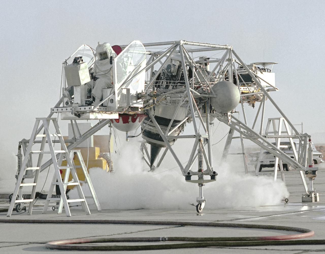
This 1964 NASA Flight Reserch Center photograph shows a ground engine test underway on the Lunar Landing Research Vehicle (LLRV) number 1. When Apollo planning was underway in 1960, NASA was looking for a simulator to profile the descent to the Moon's surface. Three concepts surfaced: an electronic simulator, a tethered device, and the ambitious Dryden contribution, a free-flying vehicle. All three became serious projects, but eventually the NASA Flight Research Center's (FRC) Landing Research Vehicle (LLRV) became the most significant one. Hubert M. Drake is credited with originating the idea, while Donald Bellman and Gene Matranga were senior engineers on the project, with Bellman, the project manager. Simultaneously, and independently, Bell Aerosystems Company, Buffalo, N.Y., a company with experience in vertical takeoff and landing (VTOL) aircraft, had conceived a similar free-flying simulator and proposed their concept to NASA headquarters. NASA Headquarters put FRC and Bell together to collaborate. The challenge was; to allow a pilot to make a vertical landing on Earth in a simulated Moon environment, one sixth of the Earth's gravity and with totally transparent aerodynamic forces in a "free flight" vehicle with no tether forces acting on it. Built of tubular aluminum like a giant four-legged bedstead, the vehicle was to simulate a lunar landing profile from around 1500 feet to the Moon's surface. To do this, the LLRV had a General Electric CF-700-2V turbofan engine mounted vertically in gimbals, with 4200 pounds of thrust. The engine, using JP-4 fuel, got the vehicle up to the test altitude and was then throttled back to support five-sixths of the vehicle's weight, simulating the reduced gravity of the Moon. Two hydrogen-peroxide lift rockets with thrust that could be varied from 100 to 500 pounds handled the LLRV's rate of descent and horizontal translations. Sixteen smaller hydrogen-peroxide rockets, mounted in pairs, gave the pilot control in pitch, yaw,
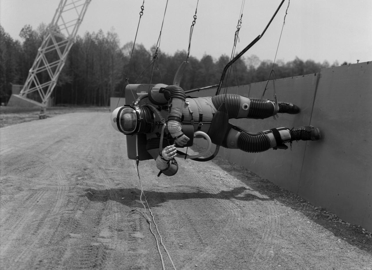
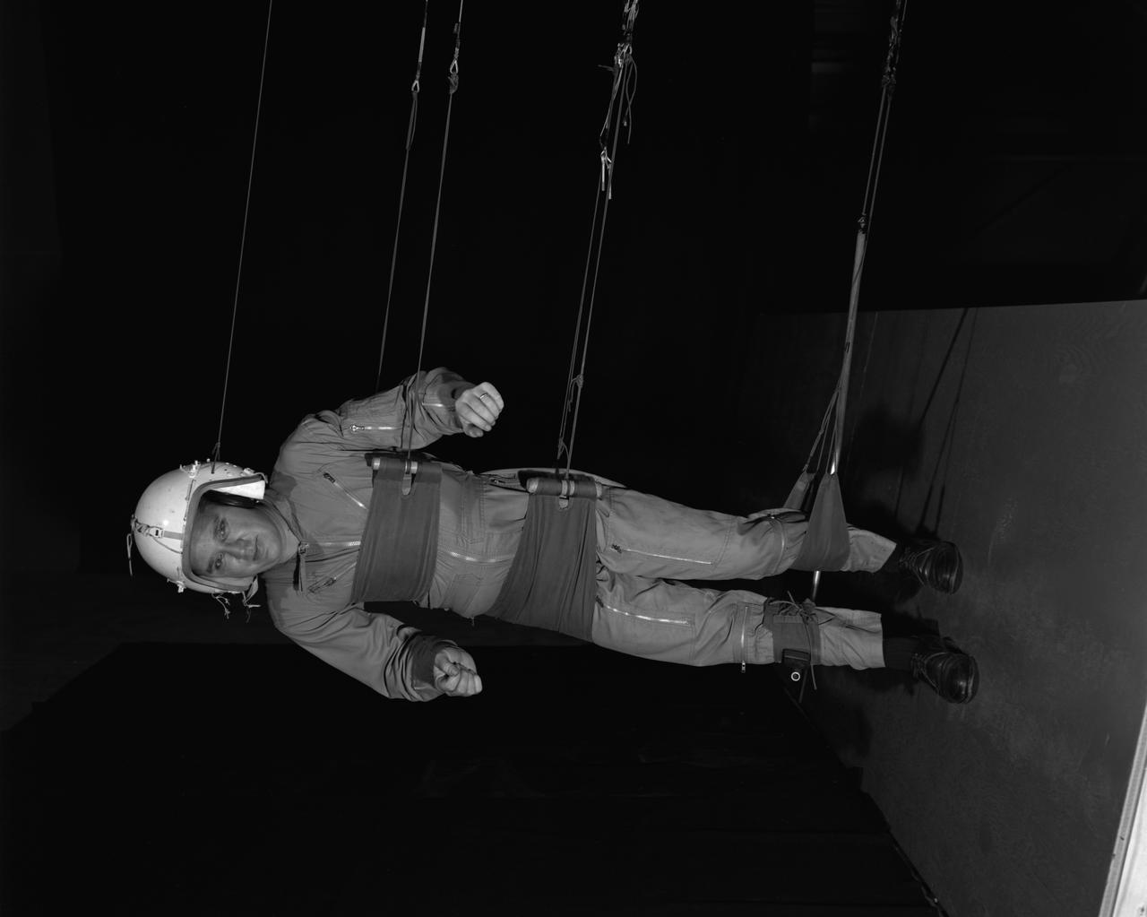
Test subject wearing the pressurized "space" suit for the Reduced Gravity Walking Simulator located at the Lunar Landing Facility. The purpose of this simulator was to study the subject while walking, jumping or running. Researchers conducted studies of various factors such as fatigue limit, energy expenditure, and speed of locomotion. A.W. Vigil described the purpose of the simulator in his paper "Discussion of Existing and Planned Simulators for Space Research," "When the astronauts land on the moon they will be in an unfamiliar environment involving, particularly, a gravitational field only one-sixth as strong as on earth. A novel method of simulating lunar gravity has been developed and is supported by a puppet-type suspension system at the end of a long pendulum. A floor is provided at the proper angle so that one-sixth of the subject's weight is supported by the floor with the remainder being supported by the suspension system. This simulator allows almost complete freedom in vertical translation and pitch and is considered to be a very realistic simulation of the lunar walking problem. For this problem this simulator suffers only slightly from the restrictions in lateral movement it puts on the test subject. This is not considered a strong disadvantage for ordinary walking problems since most of the motions do, in fact, occur in the vertical plane. However, this simulation technique would be severely restrictive if applied to the study of the extra-vehicular locomotion problem, for example, because in this situation complete six degrees of freedom are rather necessary. This technique, in effect, automatically introduces a two-axis attitude stabilization system into the problem. The technique could, however, be used in preliminary studies of extra-vehicular locomotion where, for example, it might be assumed that one axis of the attitude control system on the astronaut maneuvering unit may have failed." -- Published in James R. Hansen, Spaceflight Revolution: NASA Langley Research Center From Sputnik to Apollo, (Washington: NASA, 1995), p. 377; A.W. Vigil, "Discussion of Existing and Planned Simulators for Space Research," Paper presented at Conference on the Role of Simulation in Space Technology," Blacksburg, VA, August 17-21, 1964.
Cable system which supports the test subject on the Reduced Gravity Walking Simulator. The purpose of this simulator was to study the subject while walking, jumping or running. Researchers conducted studies of various factors such as fatigue limit, energy expenditure, and speed of locomotion. A.W. Vigil described the purpose of the simulator as follows: "When the astronauts land on the moon they will be in an unfamiliar environment involving, particularly, a gravitational field only one-sixth as strong as on earth. A novel method of simulating lunar gravity has been developed and is supported by a puppet-type suspension system at the end of a long pendulum. A floor is provided at the proper angle so that one-sixth of the subject's weight is supported by the floor with the remainder being supported by the suspension system. This simulator allows almost complete freedom in vertical translation and pitch and is considered to be a very realistic simulation of the lunar walking problem. For this problem this simulator suffers only slightly from the restrictions in lateral movement it puts on the test subject. This is not considered a strong disadvantage for ordinary walking problems since most of the motions do, in fact, occur in the vertical plane. However, this simulation technique would be severely restrictive if applied to the study of the extra-vehicular locomotion problem, for example, because in this situation complete six degrees of freedom are rather necessary. This technique, in effect, automatically introduces a two-axis attitude stabilization system into the problem. The technique could, however, be used in preliminary studies of extra-vehicular locomotion where, for example, it might be assumed that one axis of the attitude control system on the astronaut maneuvering unit may have failed." -- Published in James R. Hansen, Spaceflight Revolution: NASA Langley Research Center From Sputnik to Apollo, (Washington: NASA, 1995); A.W. Vigil, "Discussion of Existing and Planned Simulators for Space Research," Paper presented at Conference on the Role of Simulation in Space Technology," Blacksburg, VA, August 17-21, 1964.
Reduced Gravity Walking Simulator located in the hangar at Langley Research Center. The initial version of this simulator was located inside the hangar. Later a larger version would be located at the Lunar Landing Facility. The purpose of this simulator was to study the subject while walking, jumping or running. Researchers conducted studies of various factors such as fatigue limit, energy expenditure, and speed of locomotion. A.W. Vigil wrote in his paper Discussion of Existing and Planned Simulators for Space Research, When the astronauts land on the moon they will be in an unfamiliar environment involving, particularly, a gravitational field only one-sixth as strong as on earth. A novel method of simulating lunar gravity has been developed and is supported by a puppet-type suspension system at the end of a long pendulum. A floor is provided at the proper angle so that one-sixth of the subject' s weight is supported by the floor with the remainder being supported by the suspension system. This simulator allows almost complete freedom in vertical translation and pitch and is considered to be a very realistic simulation of the lunar walking problem. For this problem this simulator suffers only slightly from the restrictions in lateral movement it puts on the test subject. This is not considered a strong disadvantage for ordinary walking problems since most of the motions do, in fact, occur in the vertical plane. However, this simulation technique would be severely restrictive if applied to the study of the extra-vehicular locomotion problem, for example, because in this situation complete six degrees of freedom are rather necessary. This technique, in effect, automatically introduces a two-axis attitude stabilization system into the problem. The technique could, however, be used in preliminary studies of extra-vehicular locomotion where, for example, it might be assumed that one axis of the attitude control system on the astronaut maneuvering unit may have failed. -- Published in James R. Hansen, Spaceflight Revolution: NASA Langley Research Center From Sputnik to Apollo, NASA SP-4308, p. 377 A.W. Vigil, Discussion of Existing and Planned Simulators for Space Research, Paper presented at Conference on the Role of Simulation in Space Technology, Blacksburg, VA, August 17-21, 1964.
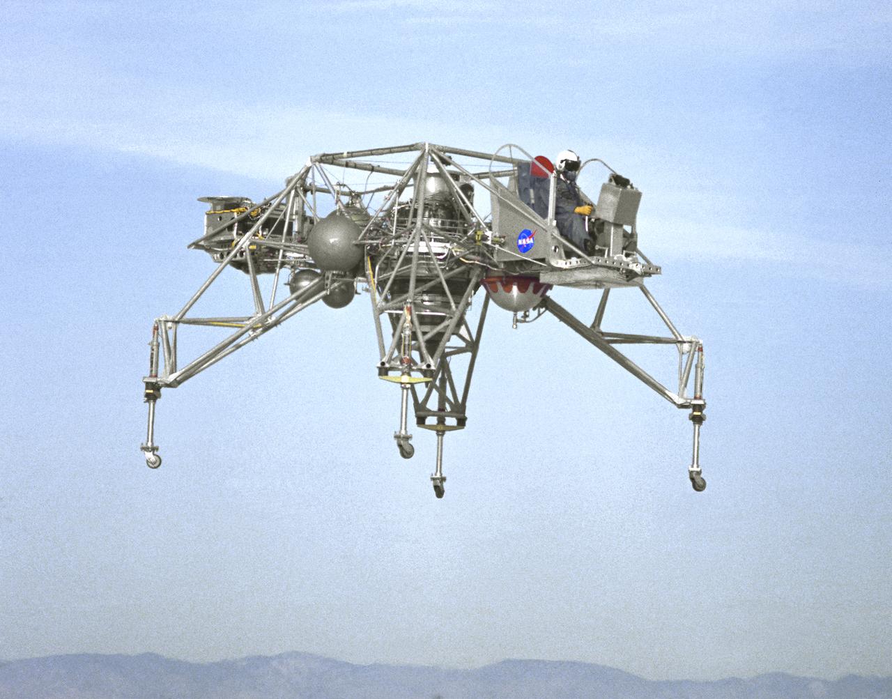
In this NASA Flight Reserch Center photograph the Lunar Landing Research Vehicle (LLRV) number 1 is shown in flight. When Apollo planning was underway in 1960, NASA was looking for a simulator to profile the descent to the Moon's surface. Three concepts surfaced: an electronic simulator, a tethered device, and the ambitious Dryden contribution, a free-flying vehicle. All three became serious projects, but eventually the NASA Flight Research Center's (FRC) Landing Research Vehicle (LLRV) became the most significant one. Hubert M. Drake is credited with originating the idea, while Donald Bellman and Gene Matranga were senior engineers on the project, with Bellman, the project manager. Simultaneously, and independently, Bell Aerosystems Company, Buffalo, N.Y., a company with experience in vertical takeoff and landing (VTOL) aircraft, had conceived a similar free-flying simulator and proposed their concept to NASA headquarters. NASA Headquarters put FRC and Bell together to collaborate. The challenge was; to allow a pilot to make a vertical landing on Earth in a simulated Moon environment, one sixth of the Earth's gravity and with totally transparent aerodynamic forces in a "free flight" vehicle with no tether forces acting on it. Built of tubular aluminum like a giant four-legged bedstead, the vehicle was to simulate a lunar landing profile from around 1500 feet to the Moon's surface. To do this, the LLRV had a General Electric CF-700-2V turbofan engine mounted vertically in gimbals, with 4200 pounds of thrust. The engine, using JP-4 fuel, got the vehicle up to the test altitude and was then throttled back to support five-sixths of the vehicle's weight, simulating the reduced gravity of the Moon. Two hydrogen-peroxide lift rockets with thrust that could be varied from 100 to 500 pounds handled the LLRV's rate of descent and horizontal translations. Sixteen smaller hydrogen-peroxide rockets, mounted in pairs, gave the pilot control in pitch, yaw, and roll. On the LLRV,
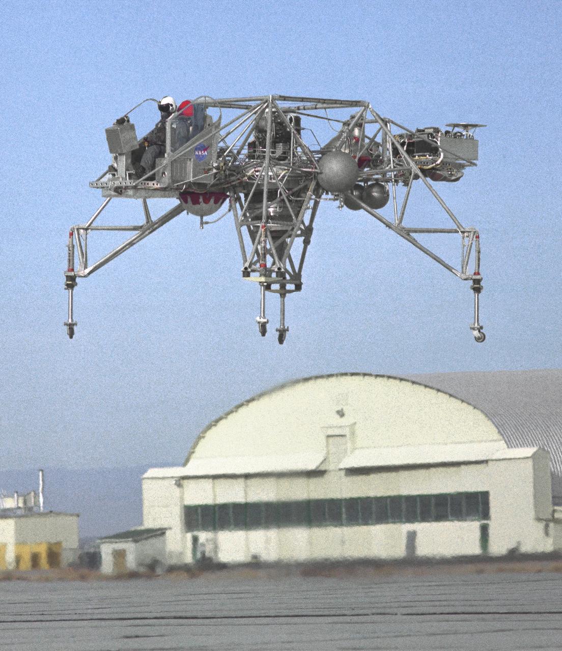
An inflight view from the left side of the Lunar Landing Research Vehicle, is shown in this 1964 NASA Flight Research Center photograph. The photograph was taken in front of the old NACA hangar located at the South Base, Edwards Air Force Base. When Apollo planning was underway in 1960, NASA was looking for a simulator to profile the descent to the Moon's surface. Three concepts surfaced: an electronic simulator, a tethered device, and the ambitious Dryden contribution, a free-flying vehicle. All three became serious projects, but eventually the NASA Flight Research Center's (FRC) Landing Research Vehicle (LLRV) became the most significant one. Hubert M. Drake is credited with originating the idea, while Donald Bellman and Gene Matranga were senior engineers on the project, with Bellman, the project manager. Simultaneously, and independently, Bell Aerosystems Company, Buffalo, N.Y., a company with experience in vertical takeoff and landing (VTOL) aircraft, had conceived a similar free-flying simulator and proposed their concept to NASA headquarters. NASA Headquarters put FRC and Bell together to collaborate. The challenge was; to allow a pilot to make a vertical landing on earth in a simulated Moon environment, one sixth of the earth's gravity and with totally transparent aerodynamic forces in a "free flight" vehicle with no tether forces acting on it. Built of tubular aluminum like a giant four-legged bedstead, the vehicle was to simulate a lunar landing profile from around 1500 feet to the Moon's surface. To do this, the LLRV had a General Electric CF-700-2V turbofan engine mounted vertically in gimbals, with 4200 pounds of thrust. The engine, using JP-4 fuel, got the vehicle up to the test altitude and was then throttled back to support five-sixths of the vehicle's weight, simulating the reduced gravity of the Moon. Two hydrogen-peroxide lift rockets with thrust that could be varied from 100 to 500 pounds handled the LLRV's rate of descent and horizontal transla
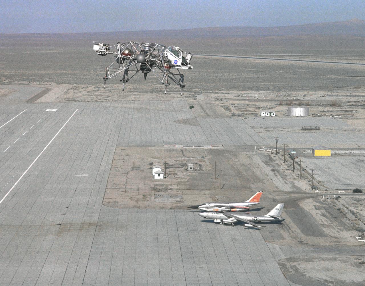
In this 1965 NASA Flight Reserch Center photograph the Lunar Landing Research Vehicle (LLRV) is shown at near maximum altitude over the south base at Edwards Air Force Base. When Apollo planning was underway in 1960, NASA was looking for a simulator to profile the descent to the moon's surface. Three concepts surfaced: an electronic simulator, a tethered device, and the ambitious Dryden contribution, a free-flying vehicle. All three became serious projects, but eventually the NASA Flight Research Center's (FRC) Landing Research Vehicle (LLRV) became the most significant one. Hubert M. Drake is credited with originating the idea, while Donald Bellman and Gene Matranga were senior engineers on the project, with Bellman, the project manager. Simultaneously, and independently, Bell Aerosystems Company, Buffalo, N.Y., a company with experience in vertical takeoff and landing (VTOL) aircraft, had conceived a similar free-flying simulator and proposed their concept to NASA headquarters. NASA Headquarters put FRC and Bell together to collaborate. The challenge was; to allow a pilot to make a vertical landing on Earth in a simulated moon environment, one sixth of the Earth's gravity and with totally transparent aerodynamic forces in a "free flight" vehicle with no tether forces acting on it. Built of tubular aluminum like a giant four-legged bedstead, the vehicle was to simulate a lunar landing profile from around 1500 feet to the moon's surface. To do this, the LLRV had a General Electric CF-700-2V turbofan engine mounted vertically in gimbals, with 4200 pounds of thrust. The engine, using JP-4 fuel, got the vehicle up to the test altitude and was then throttled back to support five-sixths of the vehicle's weight, simulating the reduced gravity of the moon. Two hydrogen-peroxide lift rockets with thrust that could be varied from 100 to 500 pounds handled the LLRV's rate of descent and horizontal translations. Sixteen smaller hydrogen-peroxide rockets, mounted in pairs, gav
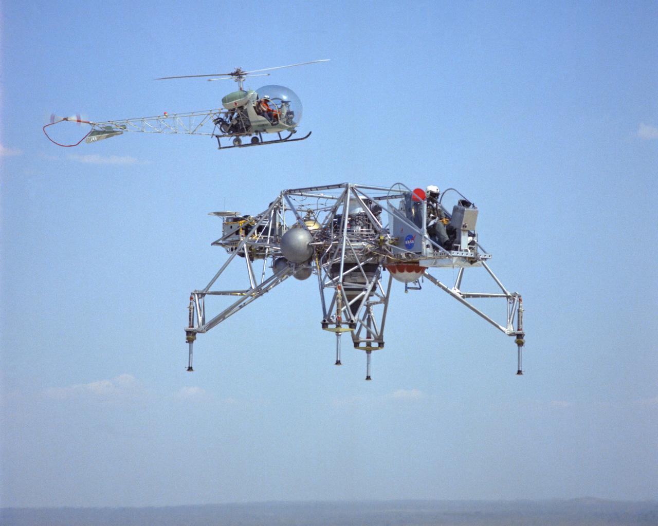
LLRV flight #1-16-61F with Bell 47 Helicopter providing chase support. The use of chase planes was a critical part of flight research well before the establishment of what was then called the NACA Muroc Flight Test Unit in September 1947 (now the NASA Dryden Flight Research Center). They act as a second set of eyes for the research pilot, warning him of any problems. When test flights of the LLRV began in October 1964, chase support for the vehicle was supplied by a Bell 47 helicopter. It could hover close by, providing information such as altitude and descent rate. LLRV test operations were phased out in late 1966 and early 1967. When Apollo planning was underway in 1960, NASA was looking for a simulator to profile the descent to the Moon's surface. Three concepts surfaced: an electronic simulator, a tethered device, and the ambitious Dryden contribution, a free-flying vehicle. All three became serious projects, but eventually the NASA Flight Research Center’s (FRC) Lunar Landing Research Vehicle (LLRV) became the most significant one. After conceptual planning and meetings with engineers from Bell Aerosystems Company, Buffalo, N.Y., NASA FRC issued a $3.6 million production contract awarded in 1963, for delivery of the first of two vehicles for flight studies. Built of tubular aluminum alloy like a giant four-legged bedstead, the vehicle was to simulate a lunar landing profile from around 1500 feet to the Moon’s surface. The LLRV had a turbofan engine mounted vertically in a gimbal, with 4200 pounds of thrust. The engine, lifted the vehicle up to the test altitude and was then throttled back to support five-sixths of the vehicle's weight, thus simulating the reduced gravity of the Moon. Two lift rockets with thrust that could be varied from 100 to 500 pounds handled the LLRV's rate of descent and horizontal translations. Sixteen smaller rockets, mounted in pairs, gave the pilot control in pitch, yaw, and roll. The pilot’s platform extended forward between t
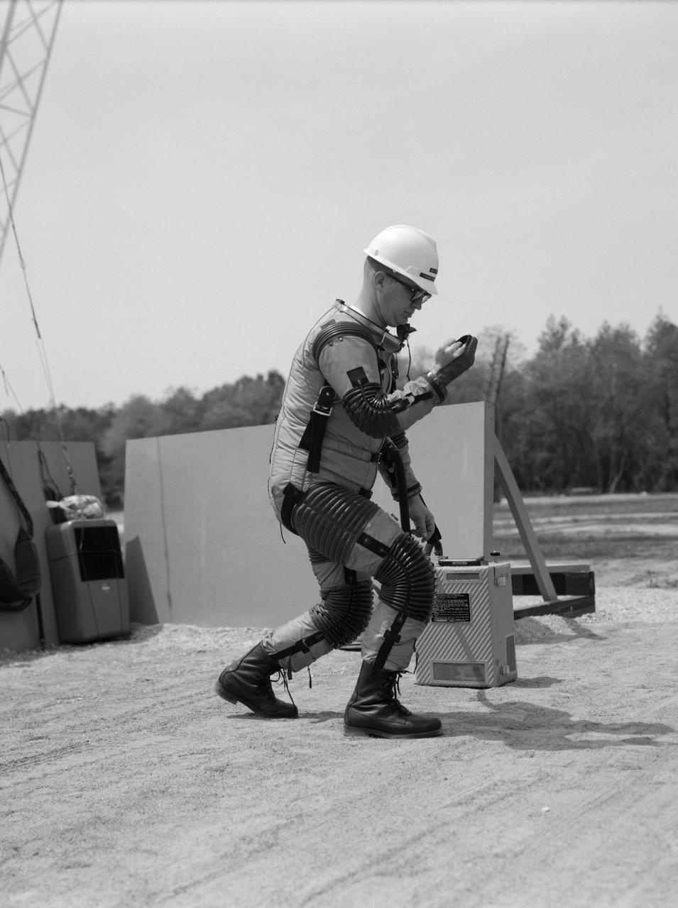
Special "space" suit for the Reduced Gravity Walking Simulator located at the Lunar Landing Facility. The purpose of this simulator was to study the subject while walking, jumping or running. Researchers conducted studies of various factors such as fatigue limit, energy expenditure, and speed of locomotion. A.W. Vigil described the purpose of the simulator in his paper "Discussion of Existing and Planned Simulators for Space Research," "When the astronauts land on the moon they will be in an unfamiliar environment involving, particularly, a gravitational field only one-sixth as strong as on earth. A novel method of simulating lunar gravity has been developed and is supported by a puppet-type suspension system at the end of a long pendulum. A floor is provided at the proper angle so that one-sixth of the subject's weight is supported by the floor with the remainder being supported by the suspension system. This simulator allows almost complete freedom in vertical translation and pitch and is considered to be a very realistic simulation of the lunar walking problem. For this problem this simulator suffers only slightly from the restrictions in lateral movement it puts on the test subject. This is not considered a strong disadvantage for ordinary walking problems since most of the motions do, in fact, occur in the vertical plane. However, this simulation technique would be severely restrictive if applied to the study of the extra-vehicular locomotion problem, for example, because in this situation complete six degrees of freedom are rather necessary. This technique, in effect, automatically introduces a two-axis attitude stabilization system into the problem. The technique could, however, be used in preliminary studies of extra-vehicular locomotion where, for example, it might be assumed that one axis of the attitude control system on the astronaut maneuvering unit may have failed." -- Published in James R. Hansen, Spaceflight Revolution: NASA Langley Research Center From Sputnik to Apollo, (Washington: NASA, 1995), p. 377; A.W. Vigil, "Discussion of Existing and Planned Simulators for Space Research," Paper presented at Conference on the Role of Simulation in Space Technology," Blacksburg, VA, August 17-21, 1964.

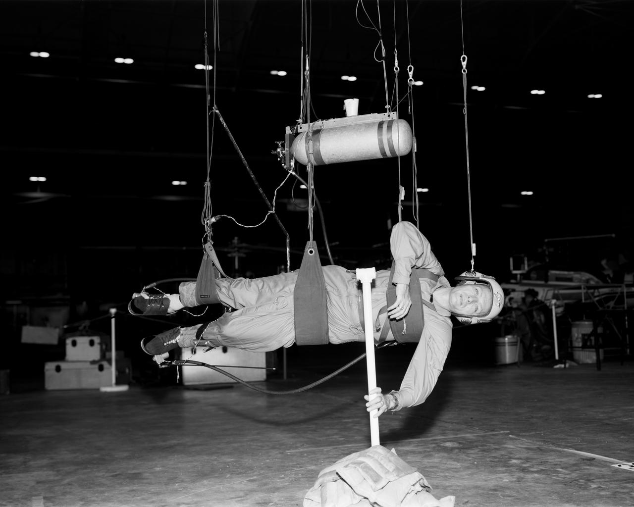
Astronaut Roger Chaffee on the Reduced Gravity Walking Simulator located at the Lunar Landing Facility. The purpose of this simulator was to study the subject while walking, jumping or running. Researchers conducted studies of various factors such as fatigue limit, energy expenditure, and speed of locomotion. A.W. Vigil, described the simulator as follows: "When the astronauts land on the moon they will be in an unfamiliar environment involving, particularly, a gravitational field only one-sixth as strong as on earth. A novel method of simulating lunar gravity has been developed and is supported by a puppet-type suspension system at the end of a long pendulum. A floor is provided at the proper angle so that one-sixth of the subject's weight is supported by the floor with the remainder being supported by the suspension system. This simulator allows almost complete freedom in vertical translation and pitch and is considered to be a very realistic simulation of the lunar walking problem. For this problem this simulator suffers only slightly from the restrictions in lateral movement it puts on the test subject. This is not considered a strong disadvantage for ordinary walking problems since most of the motions do, in fact, occur in the vertical plane. However, this simulation technique would be severely restrictive if applied to the study of the extra-vehicular locomotion problem, for example, because in this situation complete six degrees of freedom are rather necessary. This technique, in effect, automatically introduces a two-axis attitude stabilization system into the problem. The technique could, however, be used in preliminary studies of extra-vehicular locomotion where, for example, it might be assumed that one axis of the attitude control system on the astronaut maneuvering unit may have failed." -- Published in James R. Hansen, Spaceflight Revolution: NASA Langley Research Center From Sputnik to Apollo, NASA SP-4308, p. 377; A.W. Vigil, "Discussion of Existing and Planned Simulators for Space Research," Paper presented at Conference on the Role of Simulation in Space Technology," Blacksburg, VA, August 17-21, 1964.
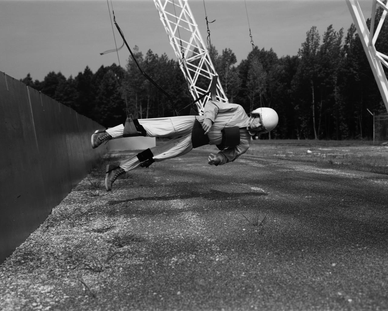
Astronaut Walt Cunningham on the Reduced Gravity Walking Simulator located at the Lunar Landing Facility. The purpose of this simulator was to study the subject while walking, jumping or running. Researchers conducted studies of various factors such as fatigue limit, energy expenditure, and speed of locomotion. A.W. Vigil described the purpose of the simulator in his paper "Discussion of Existing and Planned Simulators for Space Research," "When the astronauts land on the moon they will be in an unfamiliar environment involving, particularly, a gravitational field only one-sixth as strong as on earth. A novel method of simulating lunar gravity has been developed and is supported by a puppet-type suspension system at the end of a long pendulum. A floor is provided at the proper angle so that one-sixth of the subject's weight is supported by the floor with the remainder being supported by the suspension system. This simulator allows almost complete freedom in vertical translation and pitch and is considered to be a very realistic simulation of the lunar walking problem. For this problem this simulator suffers only slightly from the restrictions in lateral movement it puts on the test subject. This is not considered a strong disadvantage for ordinary walking problems since most of the motions do, in fact, occur in the vertical plane. However, this simulation technique would be severely restrictive if applied to the study of the extra-vehicular locomotion problem, for example, because in this situation complete six degrees of freedom are rather necessary. This technique, in effect, automatically introduces a two-axis attitude stabilization system into the problem. The technique could, however, be used in preliminary studies of extra-vehicular locomotion where, for example, it might be assumed that one axis of the attitude control system on the astronaut maneuvering unit may have failed." -- Published in James R. Hansen, Spaceflight Revolution: NASA Langley Research Center From Sputnik to Apollo, (Washington: NASA, 1995), p. 377; A.W. Vigil, "Discussion of Existing and Planned Simulators for Space Research," Paper presented at Conference on the Role of Simulation in Space Technology," Blacksburg, VA, August 17-21, 1964.
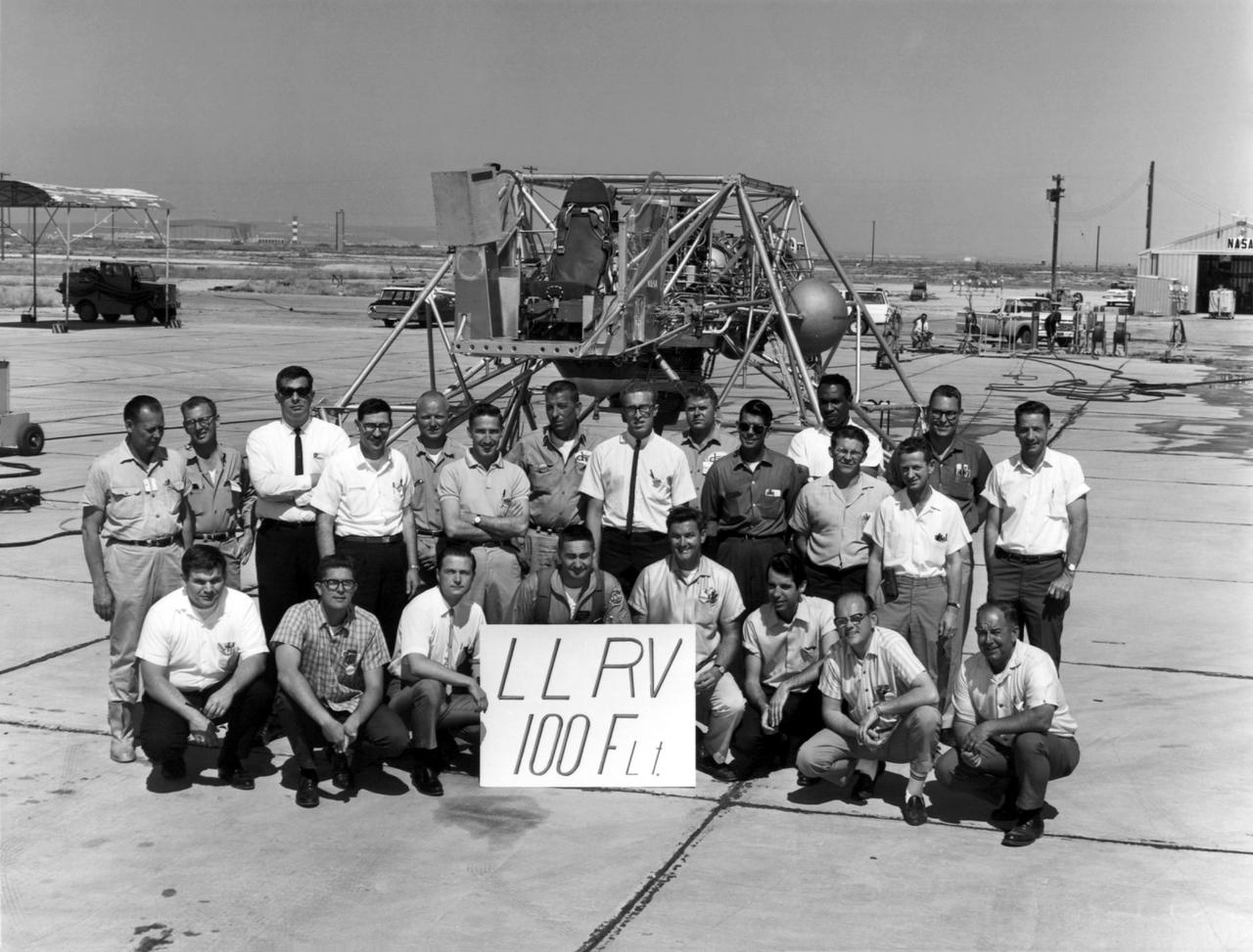
A group photo of the LLRV personnel following the program's 100th flight. The photo was taken at South Base, and was near the hangar first used by the original NACA group, at what was then called Muroc. When Apollo planning was underway in 1960, NASA was looking for a simulator to profile the descent to the moon's surface. Three concepts surfaced: an electronic simulator, a tethered device, and the ambitious Dryden contribution, a free-flying vehicle. All three became serious projects, but eventually the NASA Flight Research Center's (FRC) Landing Research Vehicle (LLRV) became the most significant one. Hubert M. Drake is credited with originating the idea, while Donald Bellman and Gene Matranga were senior engineers on the project, with Bellman, the project manager. Simultaneously, and independently, Bell Aerosystems Company, Buffalo, N.Y., a company with experience in vertical takeoff and landing (VTOL) aircraft, had conceived a similar free-flying simulator and proposed their concept to NASA headquarters. NASA Headquarters put FRC and Bell together to collaborate. The challenge was; to allow a pilot to make a vertical landing on Earth in a simulated moon environment, one sixth of the Earth's gravity and with totally transparent aerodynamic forces in a "free flight" vehicle with no tether forces acting on it. Built of tubular aluminum like a giant four-legged bedstead, the vehicle was to simulate a lunar landing profile from around 1500 feet to the moon's surface. To do this, the LLRV had a General Electric CF-700-2V turbofan engine mounted vertically in gimbals, with 4200 pounds of thrust. The engine, using JP-4 fuel, got the vehicle up to the test altitude and was then throttled back to support five-sixths of the vehicle's weight, simulating the reduced gravity of the moon. Two hydrogen-peroxide lift rockets with thrust that could be varied from 100 to 500 pounds handled the LLRV's rate of descent and horizontal translations. Sixteen smaller hydrogen-peroxide r

A researcher fills a small container used to represent a liquid hydrogen tank in preparation for a microgravity test in the 2.2-Second Drop Tower at the National Aeronautics and Space Administration (NASA) Lewis Research Center. For over a decade, NASA Lewis endeavored to make liquid hydrogen a viable propellant. Hydrogen’s light weight and high energy made it very appealing for rocket propulsion. One of the unknowns at the time was the behavior of fluids in the microgravity of space. Rocket designers needed to know where the propellant would be inside the fuel tank in order to pump it to the engine. NASA Lewis utilized sounding rockets, research aircraft, and the 2.2 Second Drop Tower to study liquids in microgravity. The drop tower, originally built as a fuel distillation tower in 1948, descended into a steep ravine. By early 1961 the facility was converted into an eight-floor, 100-foot tower connected to a shop and laboratory space. Small glass tanks, like this one, were installed in experiment carts with cameras to film the liquid’s behavior during freefall. Thousands of drop tower tests in the early 1960s provided an increased understanding of low-gravity processes and phenomena. The tower only afforded a relatively short experiment time but was sufficient enough that the research could be expanded upon using longer duration freefalls on sounding rockets or aircraft. The results of the early experimental fluid studies verified predictions made by Lewis researchers that the total surface energy would be minimized in microgravity.
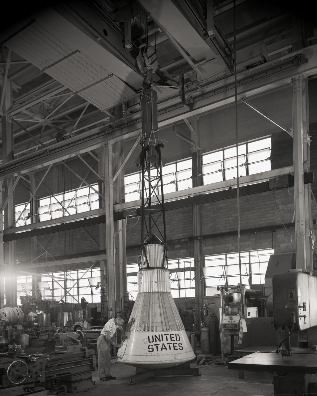
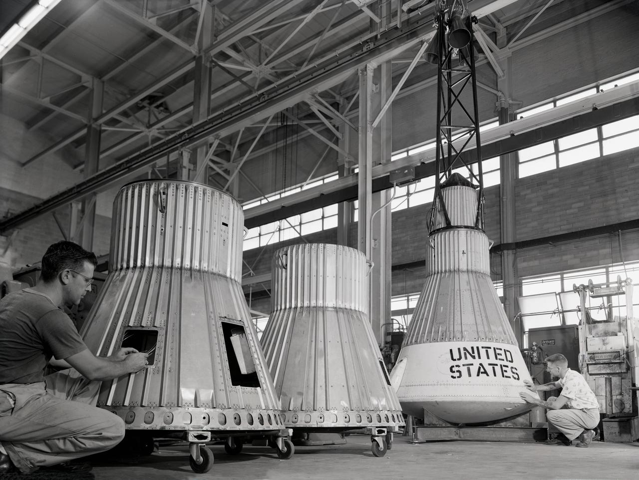
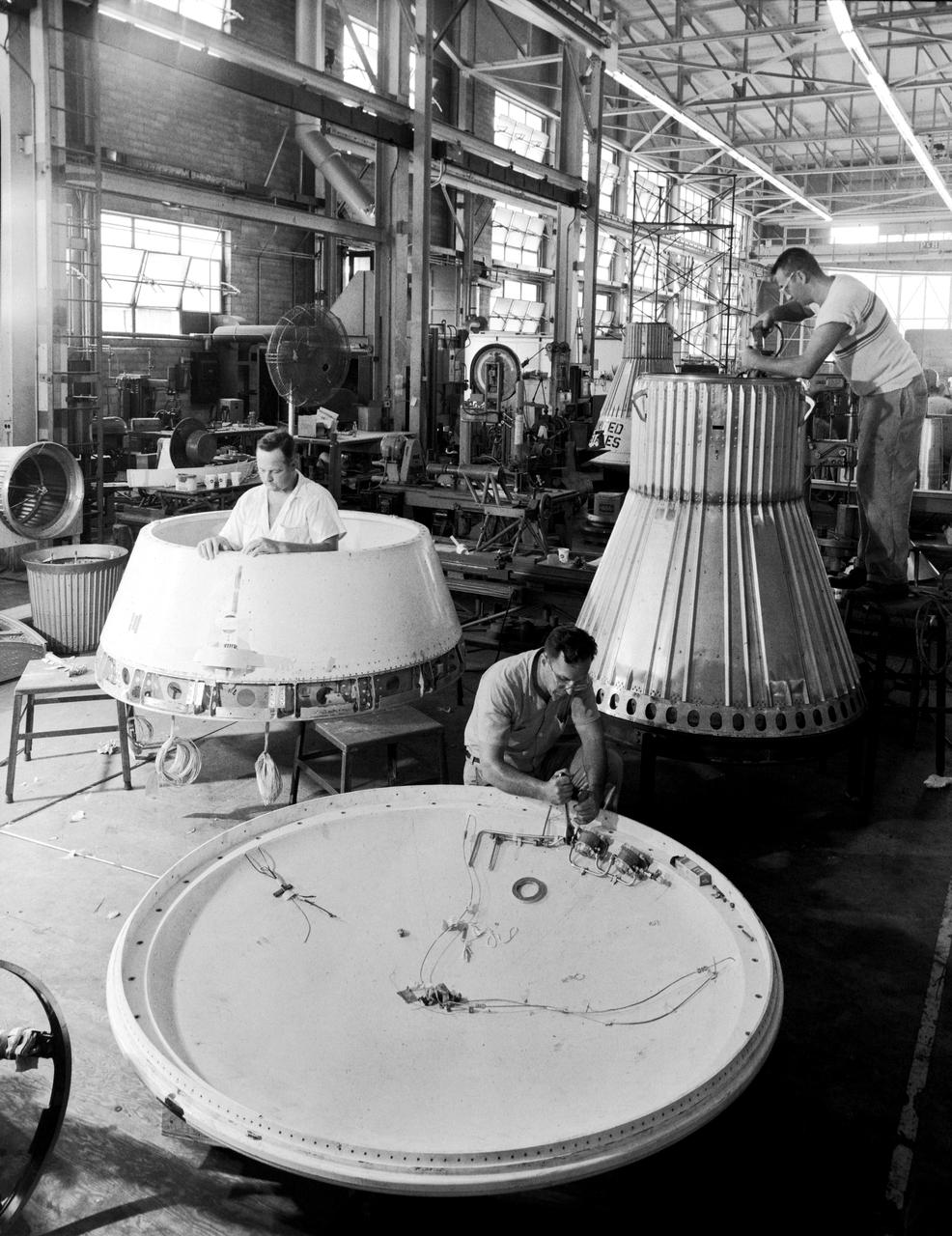
Assembling the Little Joe capsules. The capsules were manufactured in-house by Langley technicians. Three capsules are shown here in various stages of assembly. The escape tower and rocket motors shown on the completed capsule would be removed before shipping and finally assembly for launching at Wallops Island. Joseph Shortal wrote (vol. 3, p. 32): Design of the Little Joe capsules began at Langley before McDonnell started on the design of the Mercury capsule and was, therefore, a separate design. Although it was not designed to carry a man, it did have to carry a monkey. It had to meet the weight and center of gravity requirements of Mercury and withstand the same aerodynamic loads during the exit trajectory. Although in comparison with the overall Mercury Project, Little Joe was a simple undertaking, the fact that an attempt was made to condense a normal two-year project into a 6-month one with in house labor turned it into a major undertaking for Langley. Project Mercury: Little Joe: Boilerplate Mercury spacecraft undergo fabrication at the shops of the Langley Research Center. They will launched atop Little Joe rockets to test the spacecraft recovery systems. -- Published in Joseph A. Shortal, History of Wallops Station: Origins and Activities Through 1949, (Wallops Island, VA: National Aeronautics and Space Administration, Wallops Station, nd), Comment Edition. L59-4947 Technicians prepare a Little Joe launch vehicle prototype for the Mercury space program, 1959. Photograph published in Winds of Change, 75th Anniversary NASA publication, page 76, by James Schultz

Assembling the Little Joe capsules. The capsules were manufactured in-house by Langley technicians. Three capsules are shown here in various stages of assembly. The escape tower and rocket motors shown on the completed capsule would be removed before shipping and finally assembly for launching at Wallops Island. Joseph Shortal wrote (vol. 3, p. 32): Design of the Little Joe capsules began at Langley before McDonnell started on the design of the Mercury capsule and was, therefore, a separate design. Although it was not designed to carry a man, it did have to carry a monkey. It had to meet the weight and center of gravity requirements of Mercury and withstand the same aerodynamic loads during the exit trajectory. Although in comparison with the overall Mercury Project, Little Joe was a simple undertaking, the fact that an attempt was made to condense a normal two-year project into a 6-month one with in house labor turned it into a major undertaking for Langley. Project Mercury: Little Joe: Boilerplate Mercury spacecraft undergo fabrication at the shops of the Langley Research Center. They will launched atop Little Joe rockets to test the spacecraft recovery systems. -- Published in Joseph A. Shortal, History of Wallops Station: Origins and Activities Through 1949, (Wallops Island, VA: National Aeronautics and Space Administration, Wallops Station, nd), Comment Edition. L59-4947 Technicians prepare a Little Joe launch vehicle prototype for the Mercury space program, 1959. Photograph published in Winds of Change, 75th Anniversary NASA publication, page 76, by James Schultz
Assembling the Little Joe capsules. The capsules were manufactured in-house by Langley technicians. Three capsules are shown here in various stages of assembly. The escape tower and rocket motors shown on the completed capsule would be removed before shipping and finally assembly for launching at Wallops Island. Joseph Shortal wrote (vol. 3, p. 32): Design of the Little Joe capsules began at Langley before McDonnell started on the design of the Mercury capsule and was, therefore, a separate design. Although it was not designed to carry a man, it did have to carry a monkey. It had to meet the weight and center of gravity requirements of Mercury and withstand the same aerodynamic loads during the exit trajectory. Although in comparison with the overall Mercury Project, Little Joe was a simple undertaking, the fact that an attempt was made to condense a normal two-year project into a 6-month one with in house labor turned it into a major undertaking for Langley. Project Mercury: Little Joe: Boilerplate Mercury spacecraft undergo fabrication at the shops of the Langley Research Center. They will launched atop Little Joe rockets to test the spacecraft recovery systems. -- Published in Joseph A. Shortal, History of Wallops Station: Origins and Activities Through 1949, (Wallops Island, VA: National Aeronautics and Space Administration, Wallops Station, nd), Comment Edition. L59-4947 Technicians prepare a Little Joe launch vehicle prototype for the Mercury space program, 1959. Photograph published in Winds of Change, 75th Anniversary NASA publication, page 76, by James Schultz

Assembling the Little Joe capsules. The capsules were manufactured in-house by Langley technicians. Three capsules are shown here in various stages of assembly. The escape tower and rocket motors shown on the completed capsule would be removed before shipping and finally assembly for launching at Wallops Island. Joseph Shortal wrote (vol. 3, p. 32): Design of the Little Joe capsules began at Langley before McDonnell started on the design of the Mercury capsule and was, therefore, a separate design. Although it was not designed to carry a man, it did have to carry a monkey. It had to meet the weight and center of gravity requirements of Mercury and withstand the same aerodynamic loads during the exit trajectory. Although in comparison with the overall Mercury Project, Little Joe was a simple undertaking, the fact that an attempt was made to condense a normal two-year project into a 6-month one with in house labor turned it into a major undertaking for Langley. Project Mercury: Little Joe: Boilerplate Mercury spacecraft undergo fabrication at the shops of the Langley Research Center. They will launched atop Little Joe rockets to test the spacecraft recovery systems. -- Published in Joseph A. Shortal, History of Wallops Station: Origins and Activities Through 1949, (Wallops Island, VA: National Aeronautics and Space Administration, Wallops Station, nd), Comment Edition. L59-4947 Technicians prepare a Little Joe launch vehicle prototype for the Mercury space program, 1959. Photograph published in Winds of Change, 75th Anniversary NASA publication, page 76, by James Schultz

Assembling the Little Joe capsules. The capsules were manufactured in-house by Langley technicians. Three capsules are shown here in various stages of assembly. The escape tower and rocket motors shown on the completed capsule would be removed before shipping and finally assembly for launching at Wallops Island. Joseph Shortal wrote (vol. 3, p. 32): Design of the Little Joe capsules began at Langley before McDonnell started on the design of the Mercury capsule and was, therefore, a separate design. Although it was not designed to carry a man, it did have to carry a monkey. It had to meet the weight and center of gravity requirements of Mercury and withstand the same aerodynamic loads during the exit trajectory. Although in comparison with the overall Mercury Project, Little Joe was a simple undertaking, the fact that an attempt was made to condense a normal two-year project into a 6-month one with in house labor turned it into a major undertaking for Langley. Project Mercury: Little Joe: Boilerplate Mercury spacecraft undergo fabrication at the shops of the Langley Research Center. They will launched atop Little Joe rockets to test the spacecraft recovery systems. -- Published in Joseph A. Shortal, History of Wallops Station: Origins and Activities Through 1949, (Wallops Island, VA: National Aeronautics and Space Administration, Wallops Station, nd), Comment Edition. L59-4947 Technicians prepare a Little Joe launch vehicle prototype for the Mercury space program, 1959. Photograph published in Winds of Change, 75th Anniversary NASA publication, page 76, by James Schultz
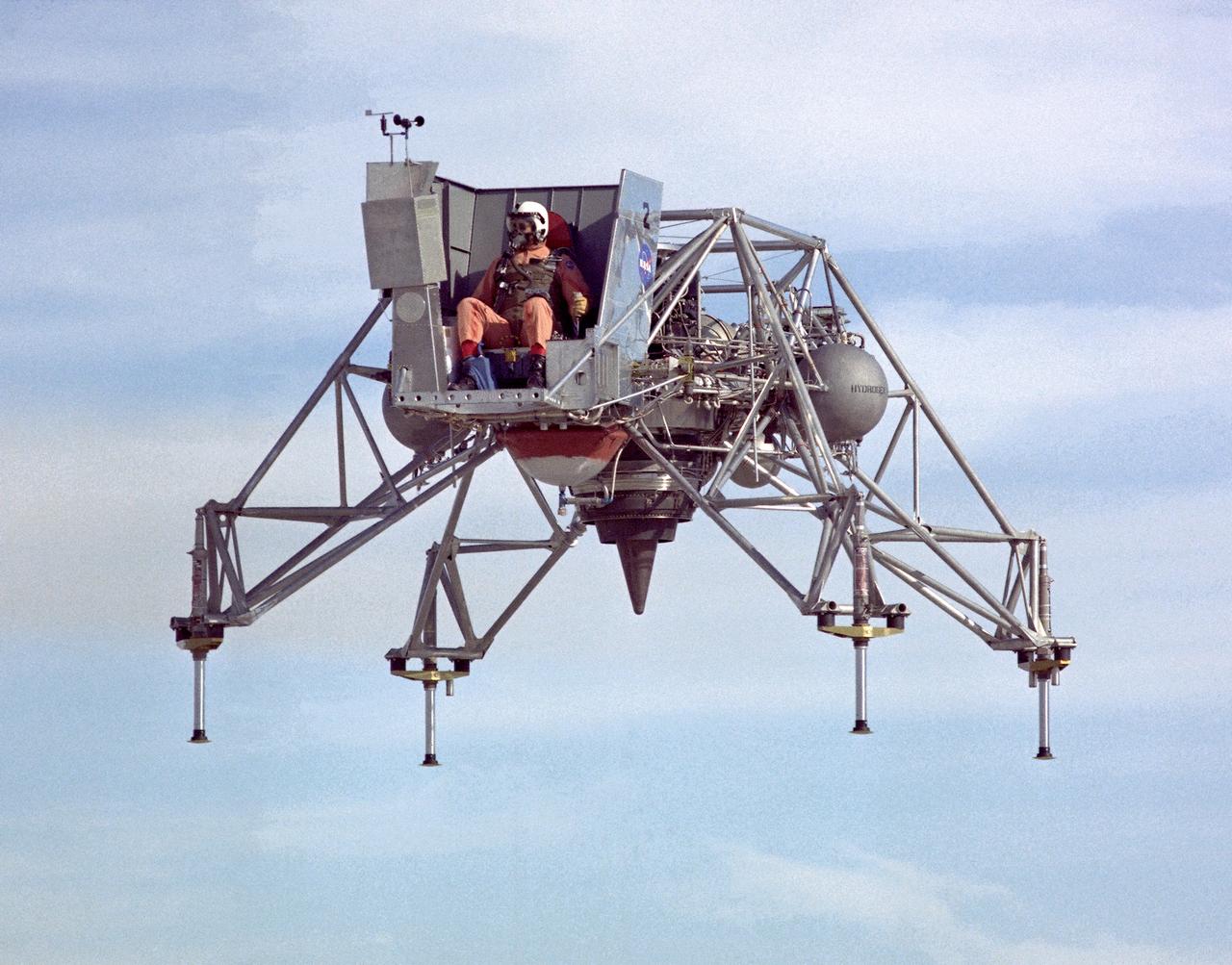
In this 1967 NASA Flight Reserch Center photograph the Lunar Landing Research Vehicle (LLRV) is viewed from the front. This photograph provideds a good view of the pilot’s platform with the restrictive cockpit view like that of he real Lunar Module (LM) When Apollo planning was underway in 1960, NASA was looking for a simulator to profile the descent to the Moon's surface. Three concepts surfaced: an electronic simulator, a tethered device, and the ambitious Dryden contribution, a free-flying vehicle. All three became serious projects, but eventually the NASA Flight Research Center’s (FRC) Lunar Landing Research Vehicle (LLRV) became the most significant one. After conceptual planning and meetings with engineers from Bell Aerosystems Company, Buffalo, N.Y., NASA FRC issued a $3.6 million production contract awarded in 1963, for delivery of the first of two vehicles for flight studies. Built of tubular aluminum alloy like a giant four-legged bedstead, the vehicle was to simulate a lunar landing profile from around 1500 feet to the Moon’s surface. The LLRV had a turbofan engine mounted vertically in a gimbal, with 4200 pounds of thrust. The engine, lifted the vehicle up to the test altitude and was then throttled back to support five-sixths of the vehicle's weight, thus simulating the reduced gravity of the Moon. Two lift rockets with thrust that could be varied from 100 to 500 pounds handled the LLRV's rate of descent and horizontal translations. Sixteen smaller rockets, mounted in pairs, gave the pilot control in pitch, yaw, and roll.. The pilot’s platform extended forward between two legs while an electronics platform, similarly located, extended rearward. The pilot had a zero-zero ejection seat that would then lift him away to safety. The two LLRVs were shipped from Bell to the FRC in April 1964, with program emphasis on vehicle No. 1. The first flight, Oct. 30, 1964, NASA research pilot Joe Walker flew it three times for a total of just under 60 seconds
Assembling the Little Joe capsules. The capsules were manufactured in-house by Langley technicians. Three capsules are shown here in various stages of assembly. The escape tower and rocket motors shown on the completed capsule would be removed before shipping and finally assembly for launching at Wallops Island. Joseph Shortal wrote (vol. 3, p. 32): Design of the Little Joe capsules began at Langley before McDonnell started on the design of the Mercury capsule and was, therefore, a separate design. Although it was not designed to carry a man, it did have to carry a monkey. It had to meet the weight and center of gravity requirements of Mercury and withstand the same aerodynamic loads during the exit trajectory. Although in comparison with the overall Mercury Project, Little Joe was a simple undertaking, the fact that an attempt was made to condense a normal two-year project into a 6-month one with in house labor turned it into a major undertaking for Langley. Project Mercury: Little Joe: Boilerplate Mercury spacecraft undergo fabrication at the shops of the Langley Research Center. They will launched atop Little Joe rockets to test the spacecraft recovery systems. -- Published in Joseph A. Shortal, History of Wallops Station: Origins and Activities Through 1949, (Wallops Island, VA: National Aeronautics and Space Administration, Wallops Station, nd), Comment Edition. L59-4947 Technicians prepare a Little Joe launch vehicle prototype for the Mercury space program, 1959. Photograph published in Winds of Change, 75th Anniversary NASA publication, page 76, by James Schultz
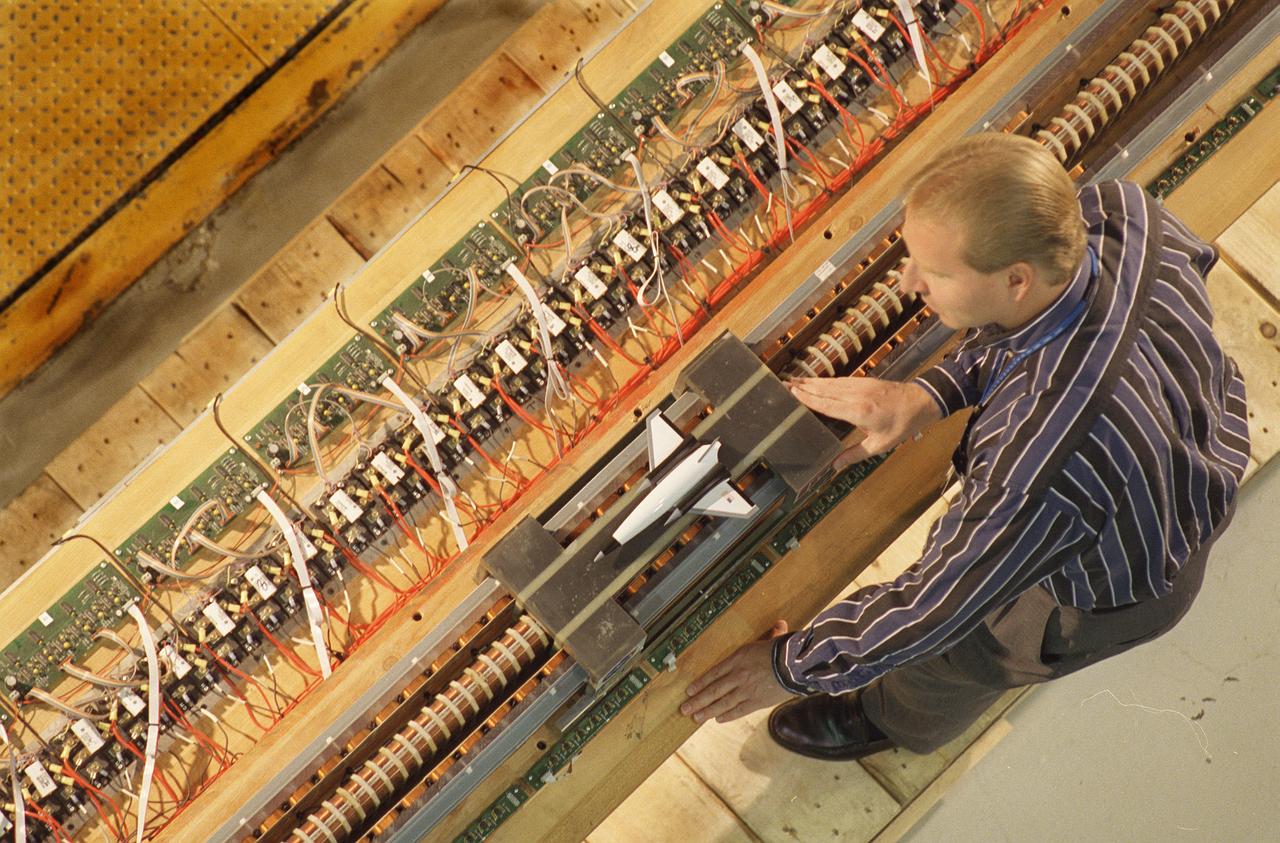
Marshall Space Flight Center’s (MSFC’s) Advanced Space Transportation Program has developed the Magnetic Launch Assist System, formerly known as the Magnetic Levitation (MagLev) technology that could give a space vehicle a running start to break free from Earth’s gravity. A Magnetic Launch Assist system would use magnetic fields to levitate and accelerate a vehicle along a track at speeds up to 600 mph. The vehicle would shift to rocket engines for launch into orbit. Similar to high-speed trains and roller coasters that use high-strength magnets to lift and propel a vehicle a couple of inches above a guideway, a Magnetic Launch Assist system would electromagnetically propel a space vehicle along the track. The tabletop experimental track for the system shown in this photograph is 44-feet long, with 22-feet of powered acceleration and 22-feet of passive braking. A 10-pound carrier with permanent magnets on its sides swiftly glides by copper coils, producing a levitation force. The track uses a linear synchronous motor, which means the track is synchronized to turn the coils on just before the carrier comes in contact with them, and off once the carrier passes. Sensors are positioned on the side of the track to determine the carrier’s position so the appropriate drive coils can be energized. MSFC engineers have conducted tests on the indoor track and a 50-foot outdoor track. The major advantages of launch assist for NASA launch vehicles is that it reduces the weight of the take-off, the landing gear, the wing size, and less propellant resulting in significant cost savings. The US Navy and the British MOD (Ministry of Defense) are planning to use magnetic launch assist for their next generation aircraft carriers as the aircraft launch system. The US Army is considering using this technology for launching target drones for anti-aircraft training.