Rear view of the Avrocar with tail, mounted on variable height struts.  Overhead doors of the wind tunnel test section open. The first Avrocar, S/N 58-7055 (marked AV-7055), after tethered testing, became the "wind tunnel" test model at NASA Ames, where it remained in storage from 1961 until 1966, when it was donated to the National Air and Space Museum, in Suitland, Maryland.
Avrocar Test in Ames 40x80 Foot Wind Tunnel.
(03/12/1976) 1/50 scale model of the 80x120 foot wind tunnel model (NFAC) in the test section of the 40x80 wind tunnel.  Model viewed from the west, mounted on a rotating ground board designed for this test. Ramp leading to ground board includes a generic building placed in front of the 80x120 inlet.
1/50 Scale Model Of The 80x120 Foot Wind Tunnel Model (NFAC) In The Test Section Of The 40x80 Wind Tunnel.
(Test 460) deHavilland Augmentor Wing 40x80 Foot Wind Tunnel.
deHavilland Augmentor Wing 40x80 Foot Wind Tunnel Test 460
APOLLO STABILITY TEST IN THE 8X6 FOOT WIND TUNNEL - MODEL IS SHOWN WITH MODULE TOWER AND CANARDS
APOLLO STABILITY TEST IN THE 8X6 FOOT WIND TUNNEL - MODEL IS SHO
(03/12/1976) 1/50 scale model of the 80x120 foot wind tunnel model (NFAC) in the test section of the 40x80 foot wind tunnel. Model mounted on a rotating ground board designed for this test, viewed from the west, oriented for North wind.
A76-0634. 1/50 Scale Model Of The 80X120 Foot Wind Tunnel Model (Nfac) In The Test Section Of The 40X80 Foot Wind Tunnel.
Rear view of the Avrocar with tail, mounted on variable height struts.  Overhead doors of the wind tunnel test section open.
AVROCAR Test in the NASA Ames 40x80 foot Wind Tunnel.
Horizontal view (side) of model, Ray Schmoranc in photo. Test #452
Semispan Airframe noise test in the 40x80 foot wind tunnel.
(03/12/1976) Overhead view of 1/50 scale model of the 80x120 foot wind tunnel model (NFAC) in the test section of the 40x80 wind tunnel at NASA Ames. Model mounted on a rotating ground board designed for this test.
1/50 Scale Model Of The 80X120 Foot Wind Tunnel Model (NFAC) In The Test Section Of The 40X80 Wind Tunnel At Nasa Ames.
Front lower view of Gates Learjet in Ames 40x80 foot wind tunnel at high angel of attack.  Test was part of a deep stall study.
Lear Jet test in Ames 40x80 Foot Wind Tunnel.
One of the first helicopter tests in the 40 x 80 wind tunnel.  John McCloud, pictured, started helicopter work in the 40 x 80.  Test 150. Testing the effects of camber on rotor blades.
Rotor Blade Test in the NACA Ames 40x80 foot Wind Tunnel.
Looking West at three test section bents in place for the Ames 40 x 80 foot wind tunnel.  Concrete model scale support visible in the middle.
Construction of the Ring leading to the Test Section of the Ames 40x80 Foot Wind Tunnel.
In this June 2017 photo, the supersonic parachute design that will land NASA's Perseverance rover on Mars on Feb. 18, 2021, undergoes testing in a wind tunnel at NASA's Ames Research Center in California's Silicon Valley.  https://photojournal.jpl.nasa.gov/catalog/PIA23916
Wind Tunnel Testing Perseverance's Parachute
The team developing the landing system for NASA Mars Science Laboratory tested the deployment of an early parachute design in mid-October 2007 inside the world largest wind tunnel, at NASA Ames Research Center, Moffett Field, California.
Testing a Parachute for Mars in World Largest Wind Tunnel
Top Plan view of Bell Rotor with Ed Verrett left frame. Test #437.
Bell Helicopter Rotor Test in the Ames 40x80 foot wind tunnel.
Orion Capsule and Launch Abort System (LAS) installed in the NASA Glenn 8x6 Supersonic Wind Tunnel (SWT) for testing.  This test is an Aero Acoustic test of the LAS. 8x6 supersonic wind tunnel test section
GRC-2007-C-02470
Active damper wind tunnel test in support of the development of Constellation/Ares.  Testing of the 1% and .548% models for active damper and wall interference assessment in support of the Ares/CLV integrated vehicle. This test occurred at the 11 foot wind tunnel at the Ames Research Center, California.  This image is extracted from  high definition video file and is the highest resolution available
Advanced Concept
Test of Lockheed YC-130 Turbo-Propeller Installation in Ames 40x80 Foot Wind Tunnel. 3/4 front view from below.
Tests of Lockheed YC-130 Turbo-Propeller Installation in Ames 40x80 Foot Wind Tunnel.
The parachute for NASA next mission to Mars passed flight-qualification testing in March and April 2009 inside the world largest wind tunnel, at NASA Ames Research Center, Moffett Field, Calif.  NASA's Mars Science Laboratory mission, to be launched in 2011 and land on Mars in 2012, will use the largest parachute ever built to fly on an extraterrestrial mission.  This image shows a duplicate qualification-test parachute inflated in an 80-mile-per-hour (36-meter-per-second) wind inside the test facility. The parachute uses a configuration called disk-gap-band. It has 80 suspension lines, measures more than 50 meters (165 feet) in length, and opens to a diameter of nearly 16 meters (51 feet). Most of the orange and white fabric is nylon, though a small disk of heavier polyester is used near the vent in the apex of the canopy due to higher stresses there. It is designed to survive deployment at Mach 2.2 in the Martian atmosphere, where it will generate up to 65,000 pounds of drag force.  The wind tunnel is 24 meters (80 feet) tall and 37 meters (120 feet) wide, big enough to house a Boeing 737. It is part of the National Full-Scale Aerodynamics Complex, operated by the Arnold Engineering Development Center of the U.S. Air Force.  http://photojournal.jpl.nasa.gov/catalog/PIA11995
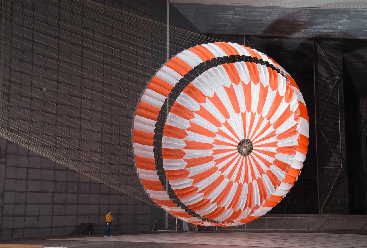
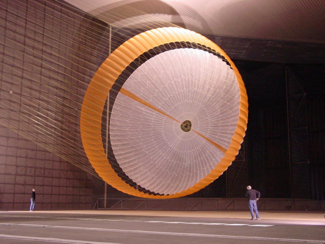
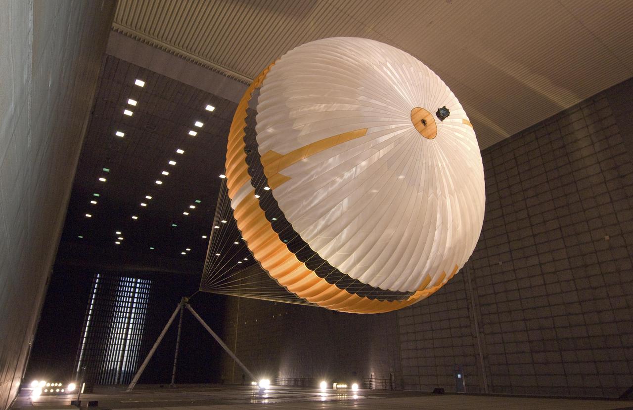
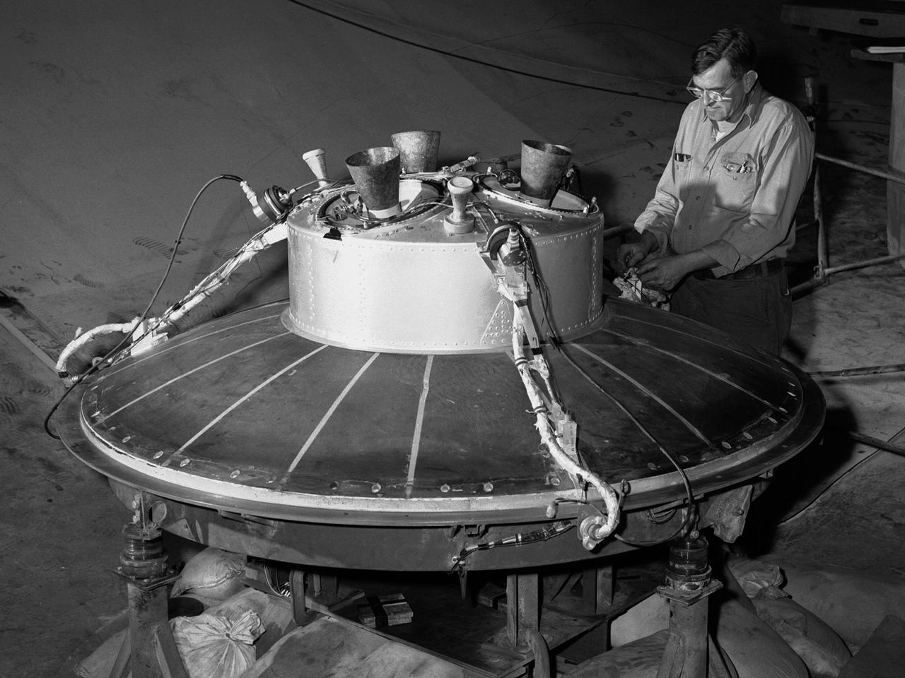
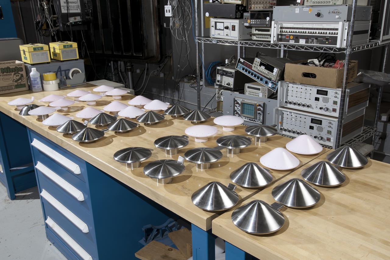
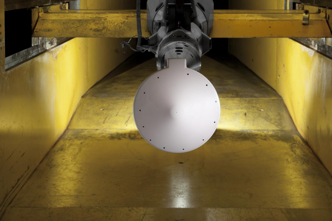
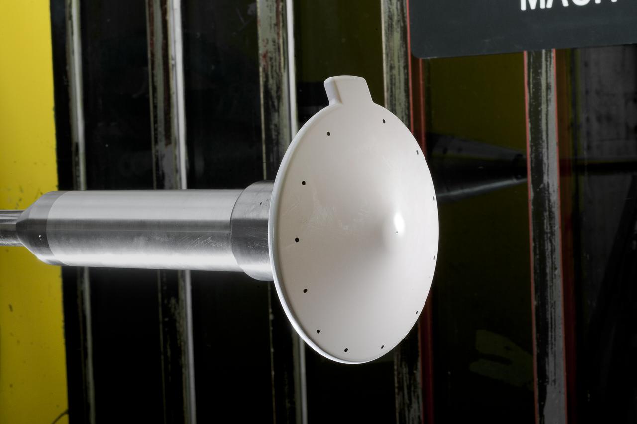
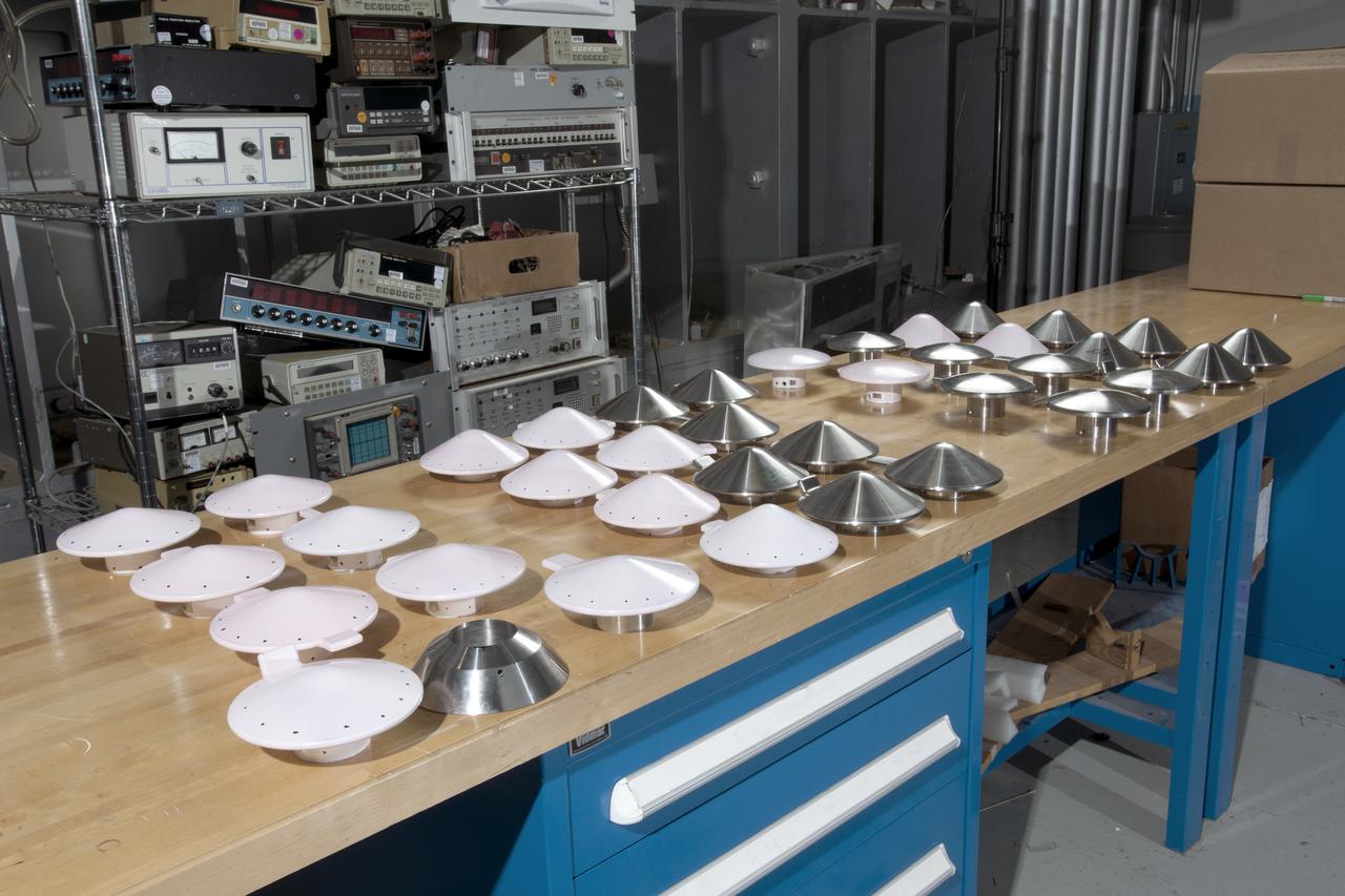
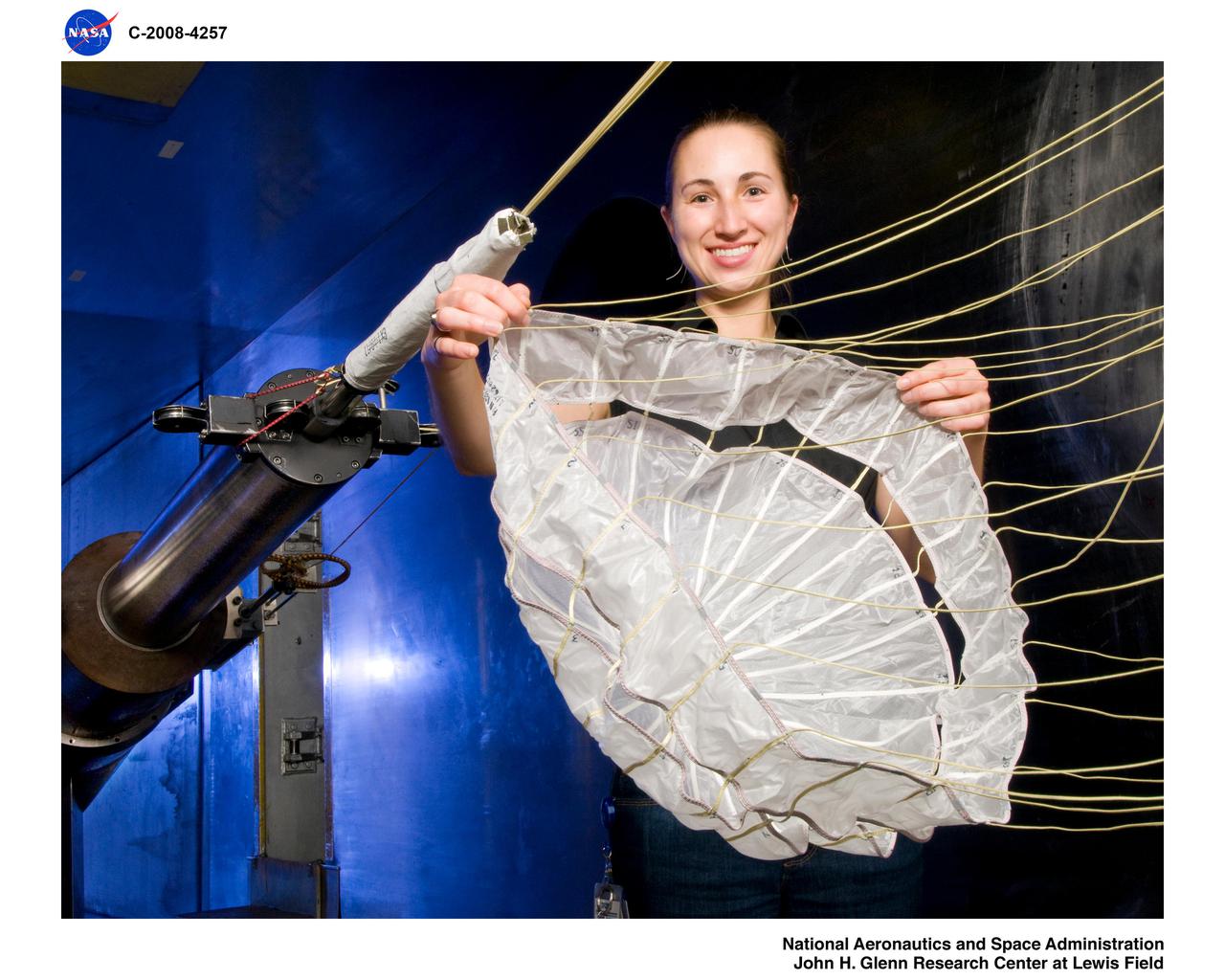
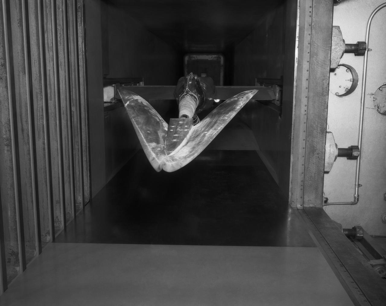
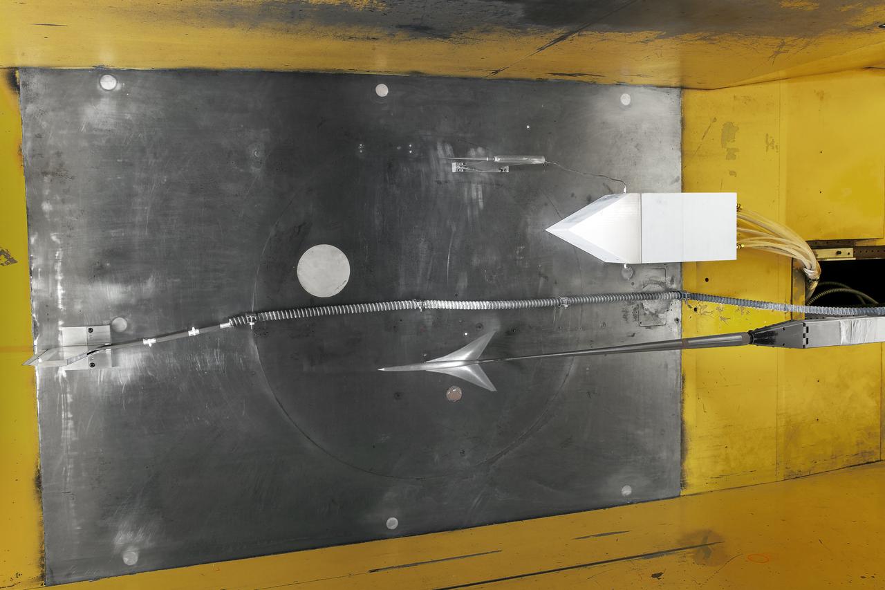
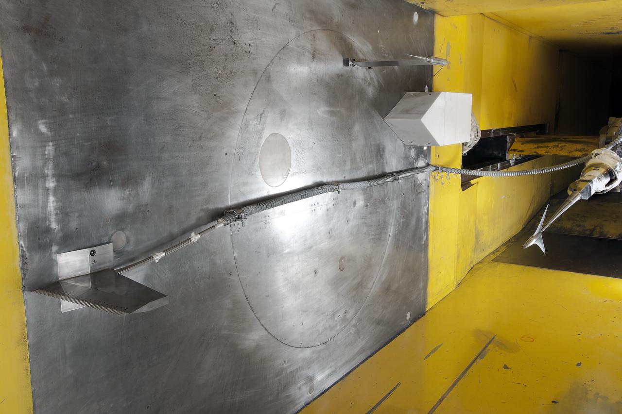
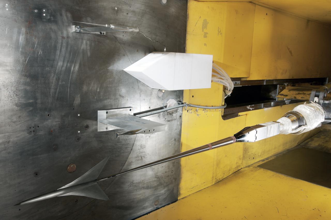
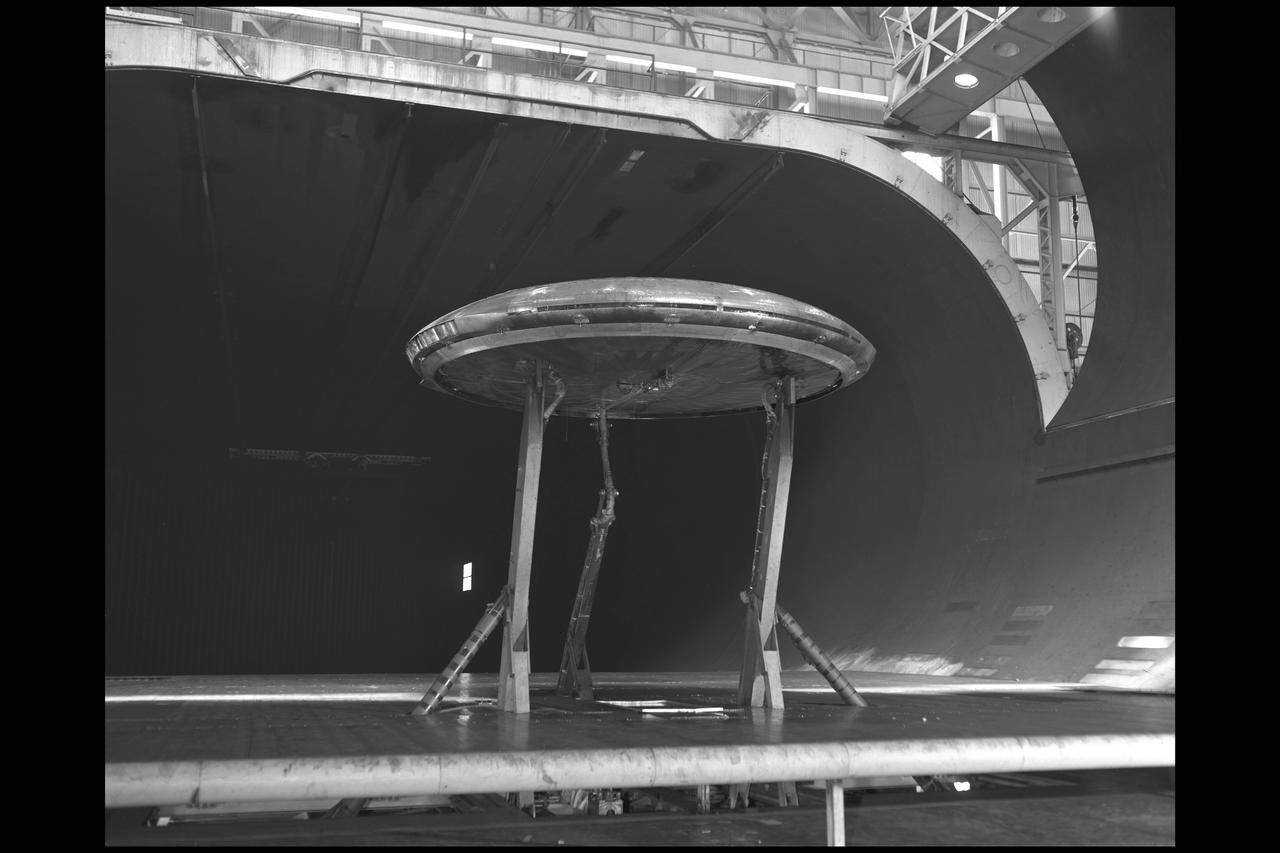
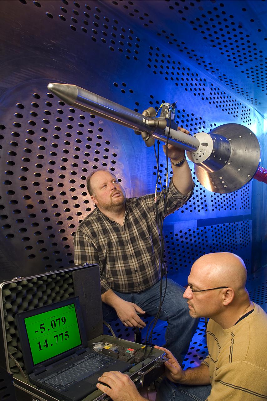
Mars Parachute Testing in World Largest Wind Tunnel
In May and June, NASA researchers tested a 7-foot wing model in the 14-by-22-Foot Subsonic Wind Tunnel at NASA’s Langley Research Center in Hampton, Virginia. The team collected data on critical propeller-wing interactions over the course of several weeks
NASA Tests Advanced Air Mobility Aircraft Wing in Langley Wind Tunnel
Truss-braced wind model installed in the Ames 11x11 Foot Wind Tunnel for testing as part of the Subsonic Ultra Green Aircraft Research Project (SUGAR)
ACD16-0013-013
Truss-braced wind model installed in the Ames 11x11 Foot Wind Tunnel for testing as part of the Subsonic Ultra Green Aircraft Research Project (SUGAR) Shown here with test engineer Greg Gatlin, Langley Research Center.
ACD16-0013-015
Vanguard 2C vertical take-off and landing (VTOL) airplane, wind tunnel test. Front view from below, model 14 1/2 feet high disk off. Nasa Ames engineer Ralph Maki in photo.  Variable height struts and ground plane, low pressure ratio, fan in wing.  02/01/1960.
Vanguard 2C VTOL Airplane Tested in the Ames 40x80 Foot Wind Tunnel.
Truss-Braced Wind Model installed in the Ames 11x11 Foot Wind Tunnel for testing. The Truss-Braced model is part of the Subsonic Ultra Green Aircraft Research Project (SUGAR)
ACD16-0013-026
0.4 Percent Scale Space Launch System Wind Tunnel Test  0.4 Percent Scale SLS model installed in the NASA Langley Research Center Unitary Plan Wind Tunnel Test Section 1 for aerodynamic force and movement testing.
0.4 Percent Scale Space Launch System Wind Tunnel Test
0.4 Percent Scale Space Launch System Wind Tunnel Test  0.4 Percent Scale SLS model installed in the NASA Langley Research Center Unitary Plan Wind Tunnel Test Section 1 for aerodynamic force and movement testing.
0.4 Percent Scale Space Launch System Wind Tunnel Test
0.4 Percent Scale Space Launch System Wind Tunnel Test  0.4 Percent Scale SLS model installed in the NASA Langley Research Center Unitary Plan Wind Tunnel Test Section 1 for aerodynamic force and movement testing.
0.4 Percent Scale Space Launch System Wind Tunnel Test
0.4 Percent Scale Space Launch System Wind Tunnel Test  0.4 Percent Scale SLS model installed in the NASA Langley Research Center Unitary Plan Wind Tunnel Test Section 1 for aerodynamic force and movement testing.
0.4 Percent Scale Space Launch System Wind Tunnel Test
0.4 Percent Scale Space Launch System Wind Tunnel Test  0.4 Percent Scale SLS model installed in the NASA Langley Research Center Unitary Plan Wind Tunnel Test Section 1 for aerodynamic force and movement testing.
0.4 Percent Scale Space Launch System Wind Tunnel Test
NASA employees Broderic J. Gonzalez, left, and David W. Shank, right, install pieces of a 7-foot wing model in preparation for testing in the 14-by-22-Foot Subsonic Wind Tunnel at NASA's Langley Research Center in Hampton, Virginia, in May 2025. The lessons learned from this testing will be shared with the public to support advanced air mobility aircraft development.
NASA Tests Advanced Air Mobility Aircraft Wing in Langley Wind Tunnel
JERRIE COBB - PILOT - TESTING GIMBAL RIG IN THE ALTITUDE WIND TUNNEL, AWT
A mechanic at the National Aeronautics and Space Administration (NASA) Lewis Research Center prepares the inverted base of a Mercury capsule for a test of its posigrade retrorockets inside the Altitude Wind Tunnel. In October 1959 NASA’s Space Task Group allocated several Project Mercury assignments to Lewis. The Altitude Wind Tunnel was modified to test the Atlas separation system, study the escape tower rocket plume, train astronauts to bring a spinning capsule under control, and calibrate the capsule’s retrorockets. The turning vanes, makeup air pipes, and cooling coils were removed from the wide western end of the tunnel to create a 51-foot diameter test chamber.    The Mercury capsule had a six-rocket retro-package affixed to the bottom of the capsule. Three of these were posigrade rockets used to separate the capsule from the booster and three were retrograde rockets used to slow the capsule for reentry into the earth’s atmosphere. Performance of the retrorockets was vital since there was no backup system.     Qualification tests of the retrorockets began in April 1960 on a retrograde thrust stand inside the southwest corner of the Altitude Wind Tunnel. These studies showed that a previous issue concerning the delayed ignition of the propellant had been resolved. Follow-up test runs verified reliability of the igniter’s attachment to the propellant. In addition, the capsule’s retrorockets were calibrated so they would not alter the capsule’s attitude when fired.
Mercury Capsule Retrorocket Test in the Altitude Wind Tunnel
Shown is a wind tunnel test of the Ares model for force/moment testing in support of the Ares/ClV integrated vehicle at Langley Research Center, Virginia.  The image is extracted from a high definition video file and is the highest resolution available.
Advanced Concept
Shown is a wind tunnel test of the Ares model for force/moment testing in support of the Ares/ClV integrated vehicle at Langley Research Center, Virginia.  The image is extracted from a high definition video file and is the highest resolution available.
Advanced Concept
A 20-inch diameter ramjet installed in the Altitude Wind Tunnel at the National Advisory Committee for Aeronautics (NACA) Lewis Flight Propulsion Laboratory. The Altitude Wind Tunnel was used in the 1940s to study early ramjet configurations. Ramjets provide a very simple source of propulsion. They are basically a tube which takes in high-velocity air, ignites it, and then expels the expanded airflow at a significantly higher velocity for thrust. Ramjets are extremely efficient and powerful but can only operate at high speeds. Therefore a turbojet or rocket was needed to launch the vehicle.    This NACA-designed 20-inch diameter ramjet was installed in the Altitude Wind Tunnel in May 1945. The ramjet was mounted under a section of wing in the 20-foot diameter test section with conditioned airflow ducted directly to the engine. The mechanic in this photograph was installing instrumentation devices that led to the control room.    NACA researchers investigated the ramjet’s overall performance at simulated altitudes up to 47,000 feet. Thrust measurements from these runs were studied in conjunction with drag data obtained during small-scale studies in the laboratory’s small supersonic tunnels. An afterburner was attached to the ramjet during the portions of the test program. The researchers found that an increase in altitude caused a reduction in the engine’s horsepower. They also determined the optimal configurations for the flameholders, which provided the engine’s ignition source.
Ramjet Testing in the NACA's Altitude Wind Tunnel
NASA researcher Norman W. Schaeffler adjusts a propellor, which is part of a 7-foot wing model that was recently tested at NASA’s Langley Research Center in Hampton, Virginia. In May and June, NASA researchers tested the wing in the 14-by-22-Foot Subsonic Wind Tunnel to collect data on critical propeller-wing interactions. The lessons learned from this testing will be shared with the public to support advanced air mobility aircraft development.
NASA Tests Advanced Air Mobility Aircraft Wing in Langley Wind Tunnel
(11/12/1971) 3/4 Scale swept augmentor wing Quest model being installed into the test section of the ames 40 x 80 foot wind tunnel, overhead doors open.
A71-8290. Swept Augmentor Wing Model Being Installed Into The Test Section Of The Ames 40 X 80 Foot Wind Tunnel.
Here you see the X-59 scaled model inside the JAXA supersonic wind tunnel during critical tests related to sound predictions.
X-59 Model Tested in Japanese Supersonic Wind Tunnel
Orion Capsule and Launch Abort System (LAS) installed in the NASA Glenn 8x6 Supersonic Wind Tunnel (SWT) for testing. 8x6 supersonic wind tunnel test section with the launch abort system for the Orion capsule
GRC-2007-C-02469
3/4 front view of model in Ames 40x80 foot wind tunnel.
Wind Tunnel Test of Stoppable Rotors in Ames 40x80ft Wind Tunnel.
Test section of the Ames 40 x 80 foot wind tunnel with the overhead doors open.  XSB2D-1 airplane being lowered onto the struts by the overhead crane. Mechanics and engineers on orchard ladders aligning the model with ball sockets on the struts. The Douglas BTD Destroyer was an American dive/ torpedo bomber developed for the United States Navy during World War II.
Installation of the Douglas XSB2D-1 in the Test Section of the 40x80 Foot Wind Tunnel at Ames.
Gemini capsule being tested in Unitary Plan Wind Tunnel.
LRC-1962-B701_P-08679
Test 1875 in Unitary Plan Wind Tunnel (UPWT) HIADS TTPM: Trim Tab study on various cone angled heat shields (TTPM) Technology Technical Performance Metric (HIADS) Hypersonic inflatable aerodynamic decelerators
Test 1875 in Unitary Plan Wind Tunnel (UPWT) HIADS TTPM
Test 1875 in Unitary Plan Wind Tunnel (UPWT) HIADS TTPM: Trim Tab study on various cone angled heat shields (TTPM) Technology Technical Performance Metric (HIADS) Hypersonic inflatable aerodynamic decelerators
Test 1875 in Unitary Plan Wind Tunnel (UPWT) HIADS TTPM
Test 1875 in Unitary Plan Wind Tunnel (UPWT) HIADS TTPM: Trim Tab study on various cone angled heat shields (TTPM) Technology Technical Performance Metric (HIADS) Hypersonic inflatable aerodynamic decelerators
Test 1875 in Unitary Plan Wind Tunnel (UPWT) HIADS TTPM
Test 1875 in Unitary Plan Wind Tunnel (UPWT) HIADS TTPM: Trim Tab study on various cone angled heat shields (TTPM) Technology Technical Performance Metric (HIADS) Hypersonic inflatable aerodynamic decelerators
Test 1875 in Unitary Plan Wind Tunnel (UPWT) HIADS TTPM
Test 1875 in Unitary Plan Wind Tunnel (UPWT) HIADS TTPM: Trim Tab study on various cone angled heat shields (TTPM) Technology Technical Performance Metric (HIADS) Hypersonic inflatable aerodynamic decelerators
Test 1875 in Unitary Plan Wind Tunnel (UPWT) HIADS TTPM
Test 1875 in Unitary Plan Wind Tunnel (UPWT) HIADS TTPM: Trim Tab study on various cone angled heat shields (TTPM) Technology Technical Performance Metric (HIADS) Hypersonic inflatable aerodynamic decelerators
Test 1875 in Unitary Plan Wind Tunnel (UPWT) HIADS TTPM
Test 1875 in Unitary Plan Wind Tunnel (UPWT) HIADS TTPM: Trim Tab study on various cone angled heat shields (TTPM) Technology Technical Performance Metric (HIADS) Hypersonic inflatable aerodynamic decelerators
Test 1875 in Unitary Plan Wind Tunnel (UPWT) HIADS TTPM
Shown is a wind tunnel test of the Ares model for force/moment testing in support of the Ares/Clv integrated vehicle at Langley Research Center, Virginia.  The image is extracted from a high definition video file and is the highest resolution available.
Advanced Concept
Mars Science Laboratory (MSL) Flexible Canopy Testing in the Glenn Research Center, 10x10 Supersonic Wind Tunnel
Mars Science Laboratory (MSL) Flexible Canopy Test
Mars Science Laboratory, MSL Flexible Canopy Test in the Glenn Research Center, 10x10 Supersonic Wind Tunnel
GRC-2008-C-04257
WS-110A Brown Bomber in Unitary Wind Tunnel Low Mach Number Test
Stage Separation Test of the Space Launch System(SLS) in the Langley Unitary Plan Wind Tunnel (UPWT). The model used High Pressure air blown through the solid rocket boosters. (SRB) to simulate the booster separation motors (BSM) firing.
The Unitary Plan Wind Tunnel(UPWT) Test 1891 Space Launch System
The Altitude Wind Tunnel (AWT) was the National Advisory Committee for Aeronautics (NACA) Aircraft Engine Research Laboratory’s largest and most important test facility in the 1940s. The AWT employed massive cooling and exhaust systems to simulate conditions found at high altitudes. The facility was originally designed to test large piston engines in a simulated flight environment. The introduction of the turbojet during the tunnel’s construction, however, changed the facility’s focus before it became operational. Its first test program was a study of the Bell YP–59A Airacomet and its General Electric I–16 turbojets.       The Airacomet was the United States’ first attempt to build a jet aircraft.  1600-horsepower centrifugal engines based on an early design by British engineer Frank Whittle were incorporated into an existing Bell airframe. In October 1942 the Airacomet was secretly test flown in the California desert. The aircraft’s performance was limited, however, and the NACA was asked to study the engines in the AWT.    The wind tunnel’s 20-foot-diameter test section was large enough to accommodate entire aircraft with its wing tips and tail removed. The I-16 engines were studied exhaustively in early 1944. They first analyzed the engines in their original configuration and then implemented a boundary layer removal duct, a new nacelle inlet, and new cooling seals. Tests of the modified version showed that the improved distribution of airflow increased the I–16’s performance by 25 percent. The Airacomet never overcame some of its inherent design issues, but the AWT went on to study nearly every emerging US turbojet model during the next decade.
First Test Program in the NACA’s Altitude Wind Tunnel
A 3670-horsepower Armstrong-Siddeley Python turboprop being prepared for tests in the Altitude Wind Tunnel at the National Advisory Committee for Aeronautics (NACA) Lewis Flight Propulsion Laboratory. In 1947 Lewis researcher Walter Olsen led a group of representatives from the military, industry, and the NACA on a fact finding mission to investigate the technological progress of British turbojet manufacturers. Afterwards several British engines, including the Python, were brought to Cleveland for testing in Lewis’s altitude facilities.     The Python was a 14-stage axial-flow compressor turboprop with a fixed-area nozzle and contra-rotating propellers. Early turboprops combined the turbojet and piston engine technologies. They could move large quantities of air so required less engine speed and thus less fuel. This was very appealing to the military for some applications. The military asked the NACA to compare the Python’s performance at sea to that at high altitudes.    The NACA researchers studied the Python in the Altitude Wind Tunnel from July 1949 through January 1950. It was the first time the tunnel was used to study an engine with the sole purpose of learning about, not improving it. They analyzed the engine’s dynamic response using a frequency response method at altitudes between 10,000 to 30,000 feet. Lewis researchers found that they could predict the dynamic response characteristics at any altitude from the data obtained from any other specific altitude. This portion of the testing was completed during a single test run.
Python Turboprop Prepared for a Test in the Altitude Wind Tunnel
UPWT Test 1998 Continuous Data Sonic Boom Test. Sonic Boom Hardward Mounted in the Langley Unitary Plan wind Tunnel(UPWT). Conical survey probes, wedge probe, and wind tunnel wall boundary layer rake. Rectangular box with wedge front end is a transducer box to that held pressure transducer for the conical probes.
(UPWT)Unitary Plan wind Tunnel Test 1998 Continuous Data Sonic B
NASA’s Sustainable Flight Demonstrator project completed wind tunnel tests on a Boeing-built X-66 full-span model during a 13-week campaign between January and March 2025. The tests were completed in the 11-Foot Transonic Unitary Plan Facility at NASA’s Ames Research Center in California’s Silicon Valley. The model underwent tests in expected flight conditions to obtain engineering data to help improve the aircraft’s design and flight simulators.
NASA’s X-66 Completes Full-Span Wind Tunnel Test
Front view of the Avrocar on variable height struts in 40x 80 wind tunnel with overhead doors open.
AVROCAR tested in the NASA Ames 40x80ft Wind Tunnel
Mars Science Laboratory, MSL Flexible Canopy Test in the Glenn Research Center, 10x10 Supersonic Wind Tunnel
GRC-2008-C-04253
Mars Science Laboratory, MSL Flexible Canopy Test in the Glenn Research Center, 10x10 Supersonic Wind Tunnel
GRC-2008-C-04256
Mars Science Laboratory, MSL Flexible Canopy Test in the Glenn Research Center, 10x10 Supersonic Wind Tunnel
GRC-2008-C-04255
Mars Science Laboratory, MSL Flexible Canopy Test in the Glenn Research Center, 10x10 Supersonic Wind Tunnel
GRC-2008-C-04254
Mars Science Laboratory, MSL Flexible Canopy Test in the Glenn Research Center, 10x10 Supersonic Wind Tunnel
GRC-2008-C-04250
Orion Capsule and Launch Abort System (LAS) installed in the NASA Glenn 8x6 Supersonic Wind Tunnel for testing.  This test is an Aero Acoustic test of the LAS.  Pictured is the calibration of the model's angle of attack
Orion Capsule and Launch Abort System (LAS) installed in the NASA Glenn 8x6 Supersonic Wind Tunnel for testing. This test is an Aero Acoustic test of the LAS. Pictured is the calibration of the model's angle of attack
Orion Capsule and Launch Abort System (LAS) installed in the NASA Glenn 8x6 Supersonic Wind Tunnel for testing.  This test is an Aero Acoustic test of the LAS.  Pictured is the calibration of the model's angle of attack
GRC-2007-C-02472
An inlet duct lowered into the 20-foot diameter test section of the Altitude Wind Tunnel at the National Advisory Committee for Aeronautics (NACA) Lewis Flight Propulsion Laboratory. Engines and hardware were prepared in the facility’s shop area. The test articles were lifted by a two-rail Shaw box crane through the high-bay and the second-story test chamber before being lowered into the test section. Technicians then spent days or weeks hooking up the supply lines and data recording telemetry.    The engines were mounted on wingspans that stretched across the test section. The wingtips attached to the balance frame’s trunnions, which could adjust the angle of attack. The balance frame included six devices that recorded data and controlled the engine. The measurements were visible in banks of manometer boards next to the control room. Photographs recorded the pressure levels in the manometer tubes, and the computing staff manually converted the data into useful measurements.    A mechanical pulley system was used to raise and lower the tunnel’s large clamshell lid into place. The lid was sealed into place using hand-turned locks accessible from the viewing platform. The lid had viewing windows above and below the test article, which permitted the filming and visual inspection of the tests.
Inlet Duct being lowered into the Altitude Wind Tunnel Test Section
Event: Forebody and Nose - Windtunnel Testing A model of the X-59 forebody is shown in the Lockheed Martin Skunk Works’ wind tunnel in Palmdale, California. These tests gave the team measurements of wind flow angle around the aircraft’s nose and confirmed computer predictions made using computational fluid dynamics (CFD) software tools. The data will be fed into the aircraft flight control system to tell the pilot the aircraft’s altitude, speed and angle. This is part of NASA’s Quesst mission which plans to help enable supersonic air travel over land.
Forebody and Nose - Windtunnel Testing