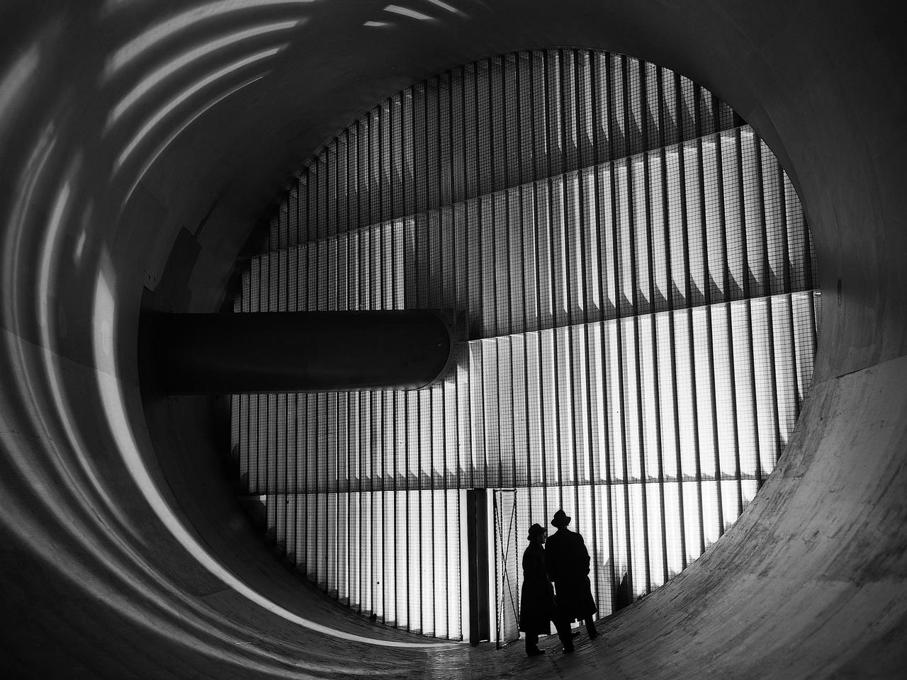
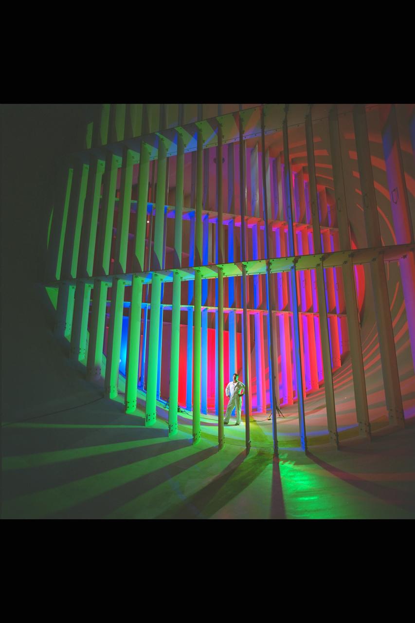
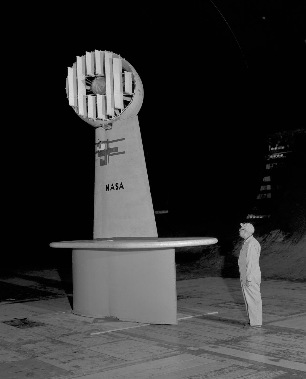
Men stand in front of turning vanes inside the Altitude Wind Tunnel (AWT) at the National Advisory Committee for Aeronautics (NACA) Aircraft Engine Research Laboratory. The AWT was the only wind tunnel capable of testing full-size aircraft engines in simulated altitude conditions. A large wooden drive fan, located on the other side of these vanes, created wind speeds up to 500 miles per hour. The drive shaft connected the fan to the induction motor located in an adjacent building. Turning vanes were located in each corner of the rectangular tunnel to straighten the airflow and direct it around the corners. This set of vanes was located in the 31-foot-diameter southeast corner of the tunnel. These elliptical panels consisted of 36 to 42 vertical vanes that were supported by three horizontal supports. The individual vanes were 2.5 feet long and half-moon shaped. The panel of vanes was affixed to the curved corner rings of the tunnel. Each set of turning vanes had a moveable vane in the middle of the lower level for personnel access. Each set of vanes took weeks to assemble before they were installed during the summer of 1943. This publicity photograph was taken just weeks after the tunnel became operational in February 1944.
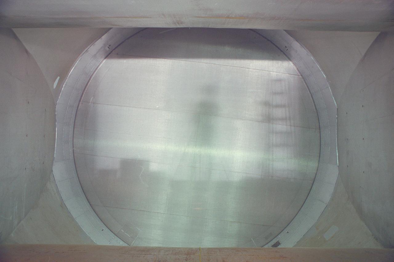
N-227 Unitary Plan Wind Tunnel Modification Project - diffuser & contraction vanes (image show reflection of photographer on vane)

An aircraft shaped wind vane is seen with the Soyuz rocket at the Baikonur Cosmodrome launch pad, Tuesday, May 28, 2013, in Kazakhstan. The launch of the Soyuz rocket to the International Space Station (ISS) with Expedition 36/37 Soyuz Commander Fyodor Yurchikhin of the Russian Federal Space Agency (Roscosmos), Flight Engineers; Luca Parmitano of the European Space Agency, and Karen Nyberg of NASA, is scheduled for 2:31a.m., Wednesday May 29, Kazakh time. Yurchikhin, Nyberg, and, Parmitano, will remain aboard the station until mid-November. Photo credit: (NASA/Bill Ingalls)
N-206 12ft. Pressure Wind Tunnel reconstruction - installation of vanes
N-206 12ft Pressure Wind Tunnel reconstruction - installation of vanes
3/4 front view with cascade exit vane in Ames 40x80 foot wind tunnel, with Tom Seymore, mechanic for Ames.
New renovated NASA Ames Research Center 12 foot Pressure Wind Tunnel, vanes
N-227 Unitary Plan Wind Tunnel Modification Project - diffuser & contraction vanes
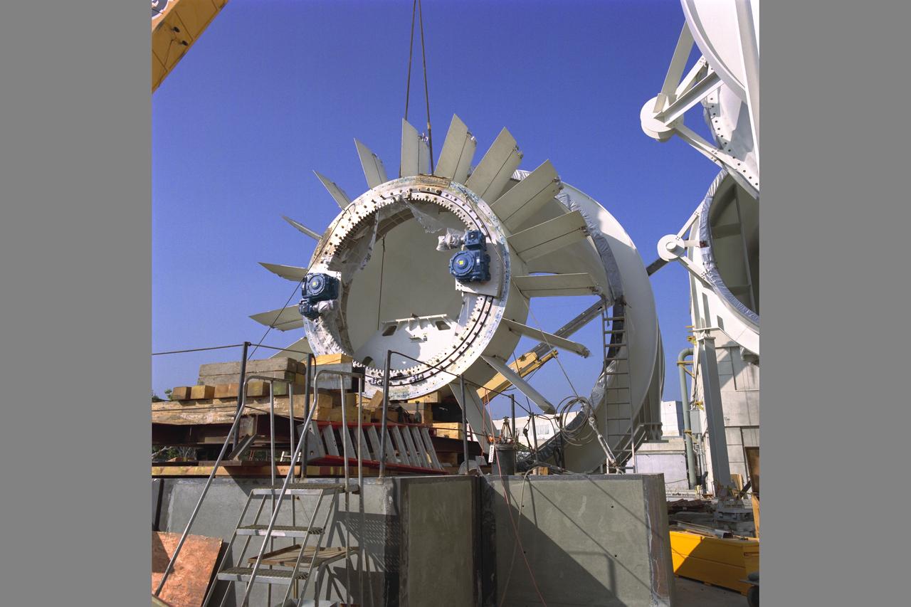
N-206 NASA Ames Research Center 12ft w.t. Pressure Wind Tunnel reconstruction - turning vanes, fan being lifted in
3/4 rear view of ducted fan model with cascade exit vane in Ames 40x80 foot wind tunnel, with Tom Seymore, mechanic for Ames.
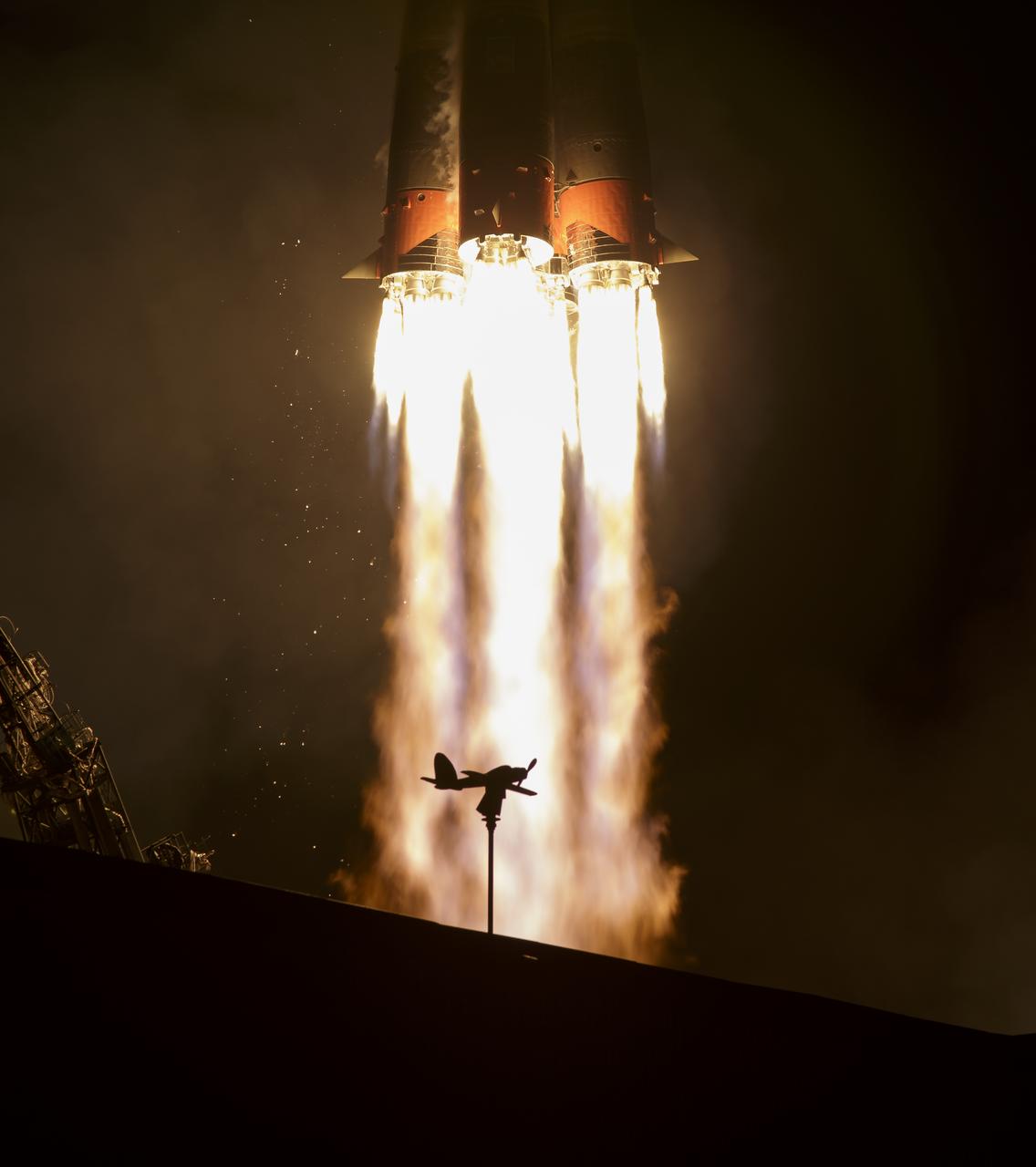
An airplane shaped wind vane is seen in silhouette as the Soyuz MS-12 spacecraft is launched with Expedition 59 crewmembers Nick Hague and Christina Koch of NASA, along with Alexey Ovchinin of Roscosmos, Friday March 15, 2019, Kazakh time (March 14 Eastern time) at the Baikonur Cosmodrome in Kazakhstan. Hague, Koch, and Ovchinin will spend six-and-a-half months living and working aboard the International Space Station. Photo Credit: (NASA/Bill Ingalls)

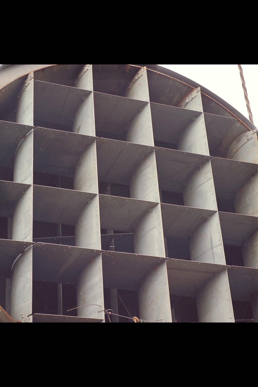
One of the two primary coolers at the Propulsion Systems Laboratory at the National Advisory Committee for Aeronautics (NACA) Lewis Flight Propulsion Laboratory. Engines could be run in simulated altitude conditions inside the facility’s two 14-foot-diameter and 24-foot-long test chambers. The Propulsion Systems Laboratory was the nation’s only facility that could run large full-size engine systems in controlled altitude conditions. At the time of this photograph, construction of the facility had recently been completed. Although not a wind tunnel, the Propulsion Systems Laboratory generated high-speed airflow through the interior of the engine. The air flow was pushed through the system by large compressors, adjusted by heating or refrigerating equipment, and de-moisturized by air dryers. The exhaust system served two roles: reducing the density of the air in the test chambers to simulate high altitudes and removing hot gases exhausted by the engines being tested. It was necessary to reduce the temperature of the extremely hot engine exhaust before the air reached the exhauster equipment. As the air flow exited through exhaust section of the test chamber, it entered into the giant primary cooler seen in this photograph. Narrow fins or vanes inside the cooler were filled with water. As the air flow passed between the vanes, its heat was transferred to the cooling water. The cooling water was cycled out of the system, carrying with it much of the exhaust heat.
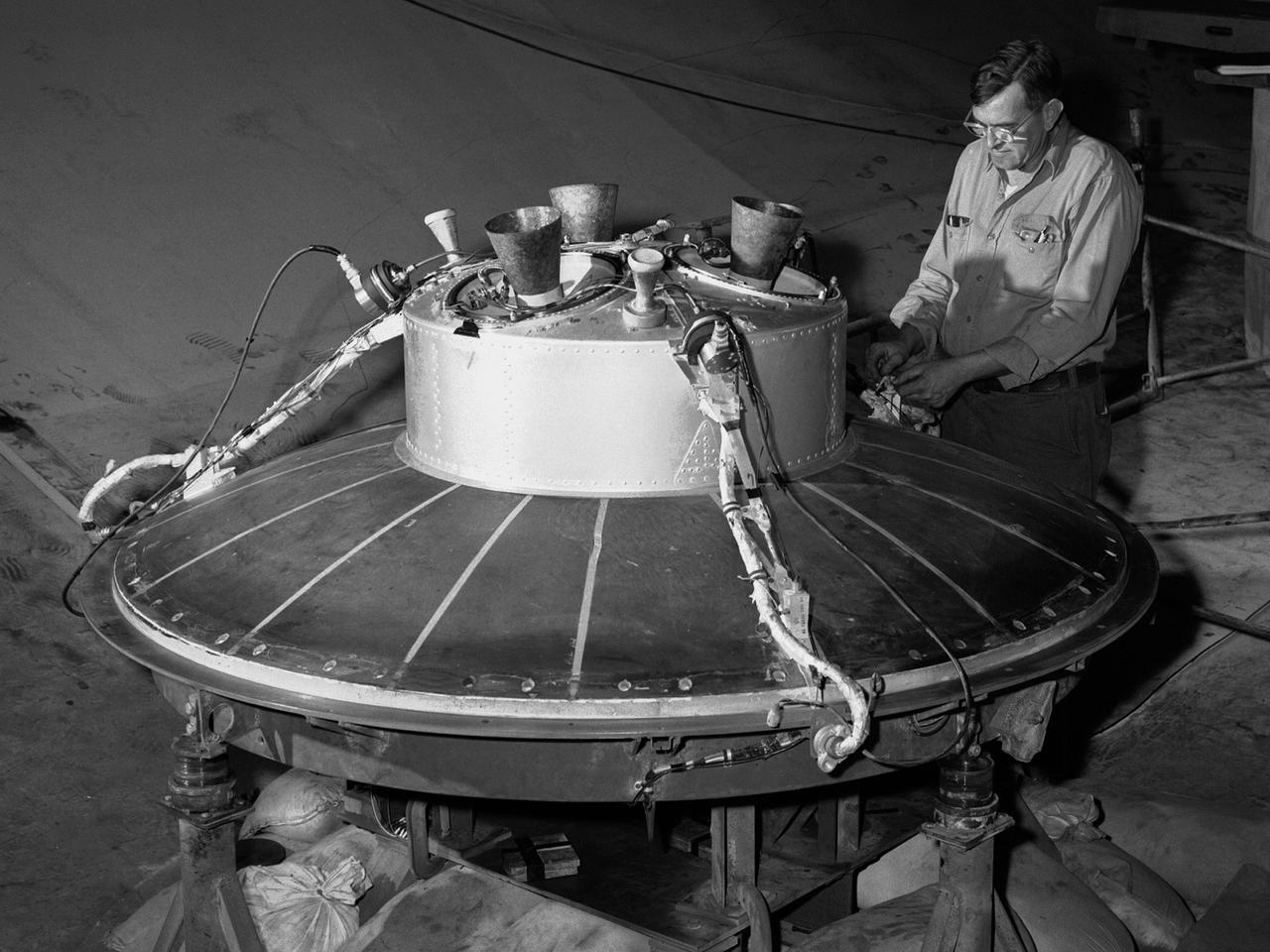
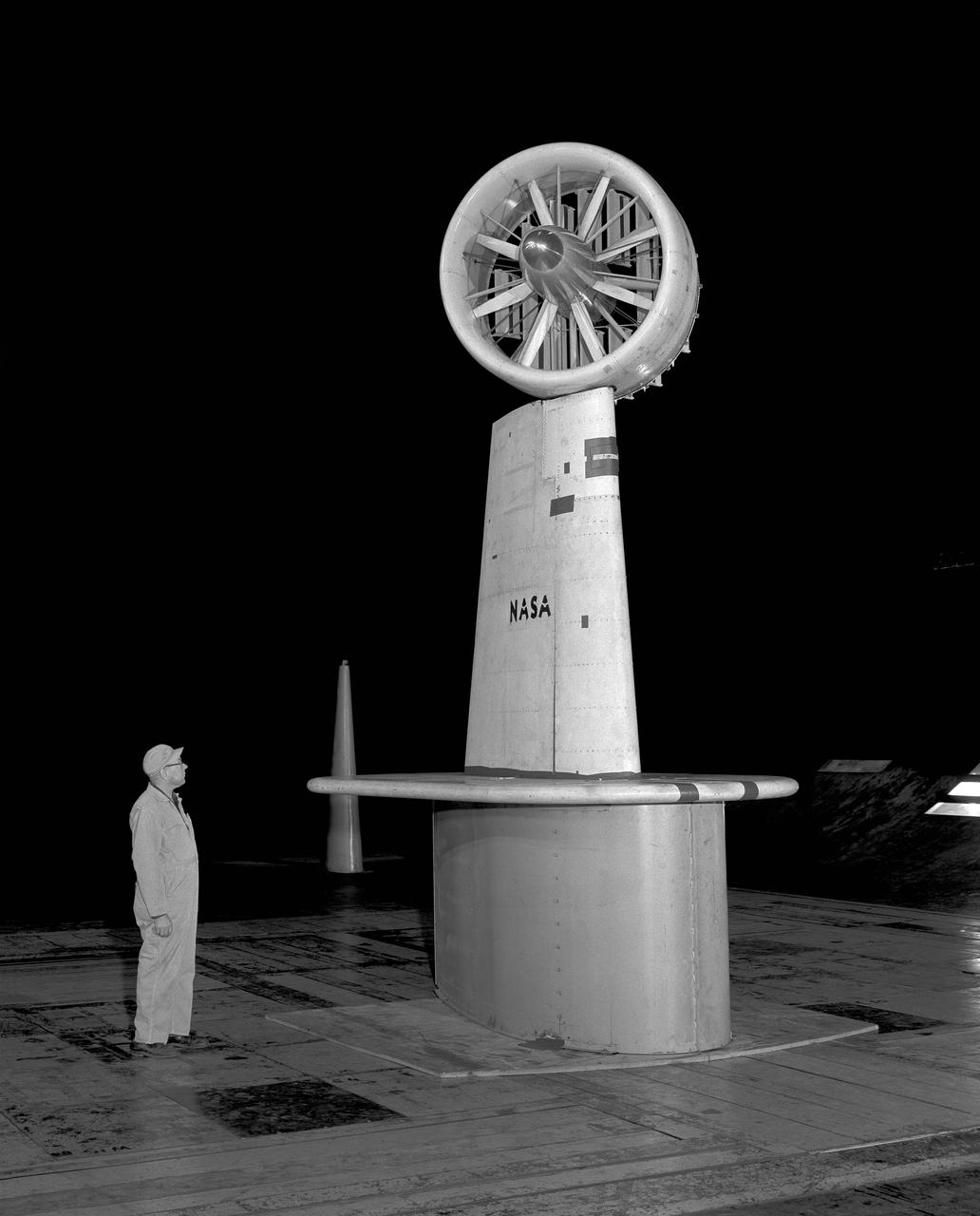
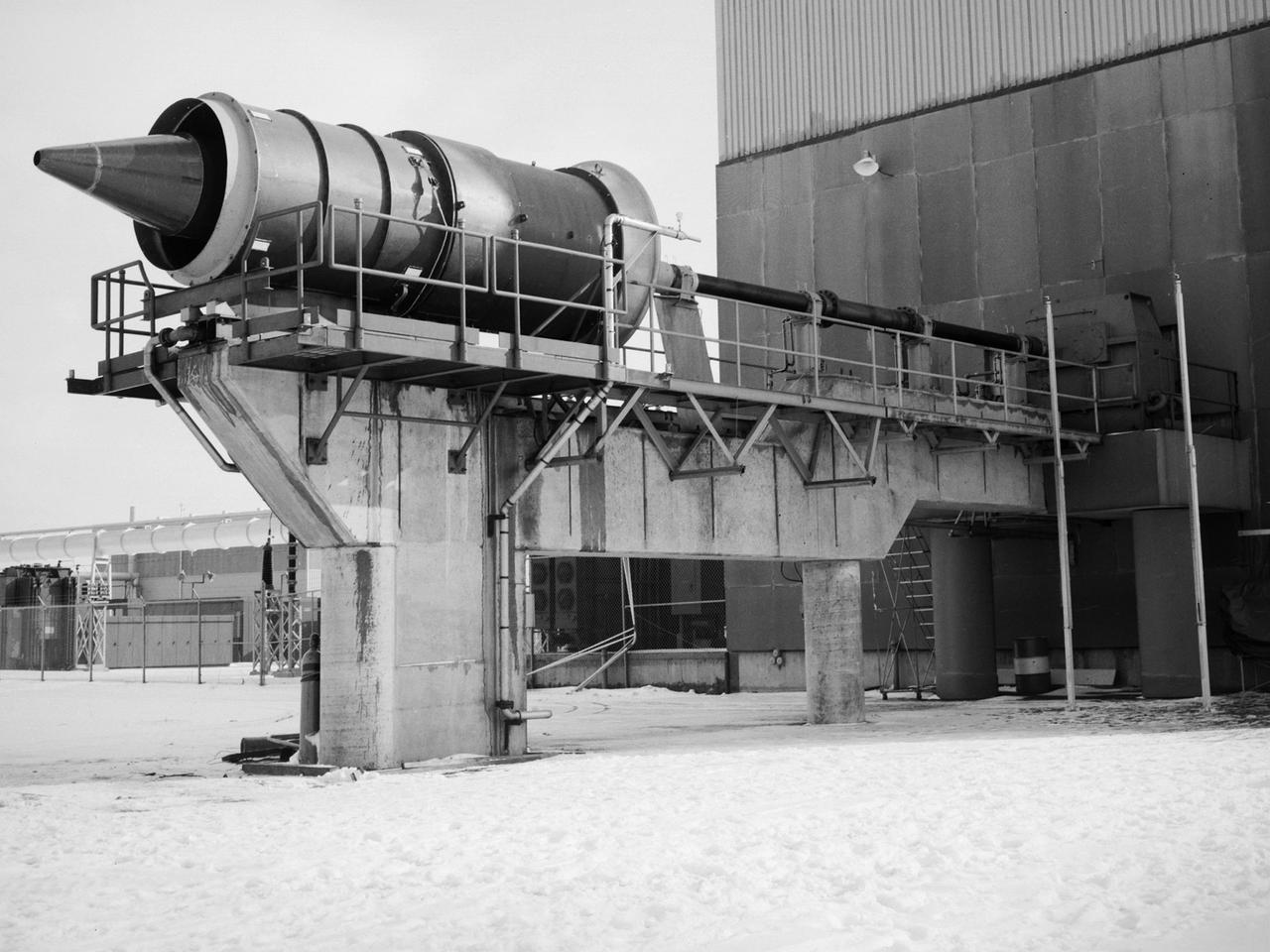
A mechanic at the National Aeronautics and Space Administration (NASA) Lewis Research Center prepares the inverted base of a Mercury capsule for a test of its posigrade retrorockets inside the Altitude Wind Tunnel. In October 1959 NASA’s Space Task Group allocated several Project Mercury assignments to Lewis. The Altitude Wind Tunnel was modified to test the Atlas separation system, study the escape tower rocket plume, train astronauts to bring a spinning capsule under control, and calibrate the capsule’s retrorockets. The turning vanes, makeup air pipes, and cooling coils were removed from the wide western end of the tunnel to create a 51-foot diameter test chamber. The Mercury capsule had a six-rocket retro-package affixed to the bottom of the capsule. Three of these were posigrade rockets used to separate the capsule from the booster and three were retrograde rockets used to slow the capsule for reentry into the earth’s atmosphere. Performance of the retrorockets was vital since there was no backup system. Qualification tests of the retrorockets began in April 1960 on a retrograde thrust stand inside the southwest corner of the Altitude Wind Tunnel. These studies showed that a previous issue concerning the delayed ignition of the propellant had been resolved. Follow-up test runs verified reliability of the igniter’s attachment to the propellant. In addition, the capsule’s retrorockets were calibrated so they would not alter the capsule’s attitude when fired.
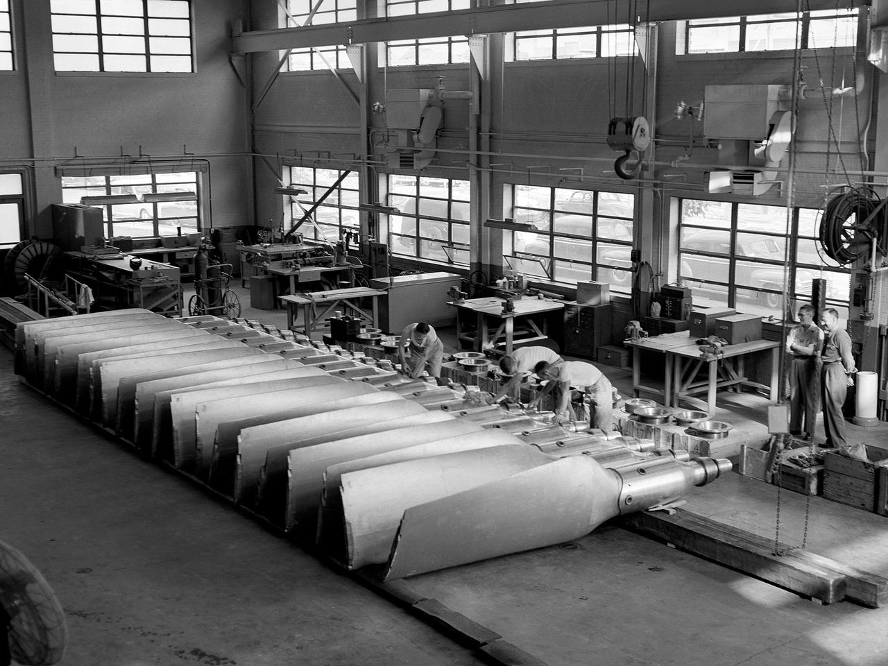
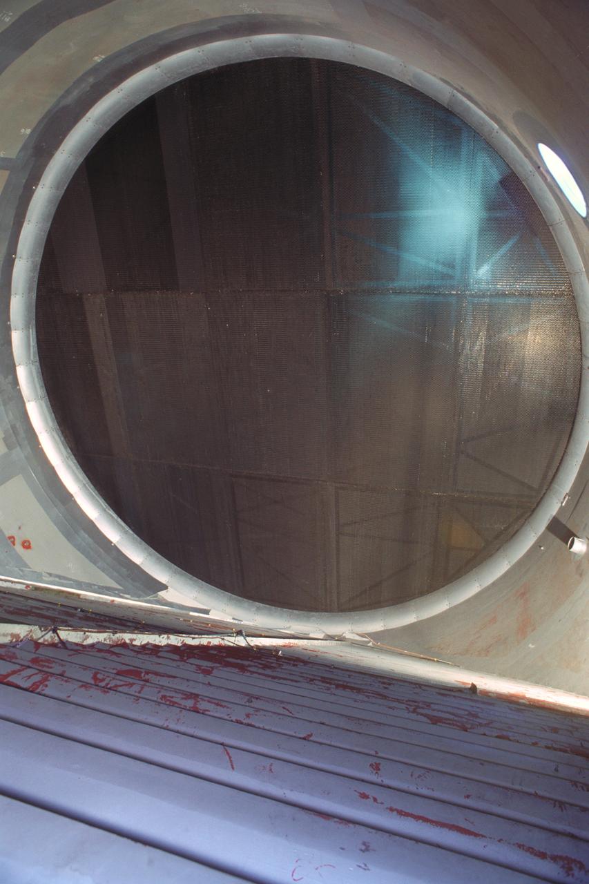
New wooden fan blades being prepared for installation in the Altitude Wind Tunnel at the National Advisory Committee for Aeronautics (NACA) Lewis Flight Propulsion Laboratory. The facility underwent a major upgrade in 1951 to increase its operating capacities in order to handle the new, more powerful turbojet engines being manufactured in the 1950s. The fan blades were prepared in the shop area, seen in this photograph, before being lowered through a hole in the tunnel and attached to the drive shaft. A new drive bearing and tail faring were also installed on the fan as part of this rehab project. A 12-bladed 31-foot-diameter spruce wood fan generated the 300 to 500 mile-per-hour airflow through the tunnel. An 18,000-horsepower General Electric induction motor located in the rear corner of the Exhauster Building drove the fan at 410 revolutions per minute. An extension shaft, sealed in the tunnel’s shell with flexible couplings that allowed for the movement of the shell, connected the motor to the fan. A bronze screen secured to the turning vanes protected the fan against damage from any engine parts sailing through the tunnel. Despite this screen the blades did become worn or cracked over time and had to be replaced.
The Fan Noise Test Facility built at the Lewis Research Center to obtain far-field noise data for the National Aeronautics and Space Administration (NASA) and General Electric Quiet Engine Program. The engine incorporated existing noise reduction methods into an engine of similar power to those that propelled the Boeing 707 or McDonnell-Douglas DC-8 airliner. The new the low-bypass ratio turbofan engines of the 1960s were inherently quieter than their turbojet counterparts, researchers had a better grasp of the noise generation problem, and new acoustic technologies had emerged. Lewis contracted General Electric in 1969 to build and aerodynamically test three experimental engines with 72-inch diameter fans. The engines were then brought to Lewis and tested with an acoustically treated nacelle. This Fan Noise Test Facility was built off of the 10- by 10-Foot Supersonic Wind Tunnel’s Main Compressor and Drive Building. Lewis researchers were able to isolate the fan’s noise during these initial tests by removing the core of the engine. The Lewis test rig drove engines to takeoff tip speeds of 1160 feet per second. The facility was later used to test a series of full-scale model fans and fan noise suppressors to be used with the quiet engine. NASA researchers predicted low-speed single-stage fans without inlet guide vanes and with large spacing between rotors and stators would be quieter. General Electric modified a TF39 turbofan engine by removing the the outer protion of the fan and spacing the blade rows of the inner portion. The tests revealed that the untreated version of the engine generated less noise than was anticipated, and the acoustically treated nacelle substantially reduced engine noise.
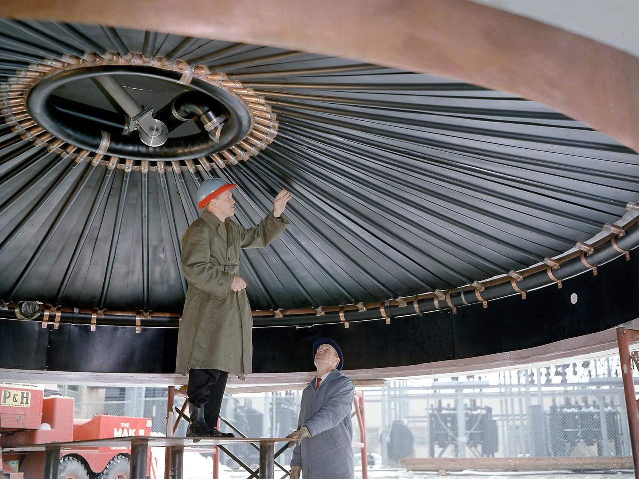
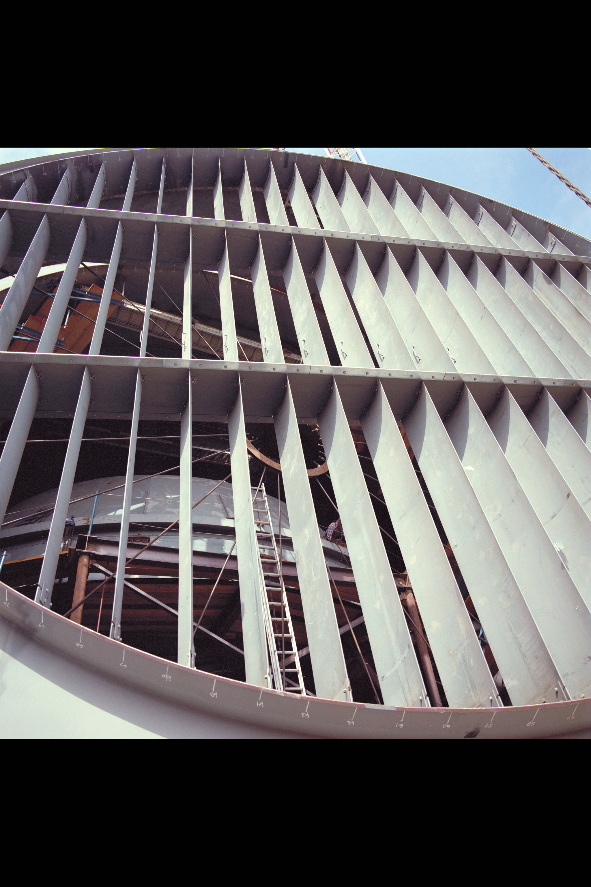
Engineers at the National Aeronautics and Space Administration (NASA) Lewis Research Center inspect the nitrogen baffle in the interior of the 22.5-foot diameter dome at the Space Power Chambers. In 1961 NASA Lewis management decided to convert the Altitude Wind Tunnel into two large test chambers and renamed the facility the Space Power Chambers. The conversion, which took over two years, included removing the tunnel’s drive fan, exhaust scoop, and turning vanes from the east end and inserting bulkheads to seal off the new chambers within the tunnel. The eastern section of the tunnel became a vacuum chamber capable of simulating 100 miles altitude. In 1962 NASA management decided to use the new vacuum chamber exclusively to study the second-stage rocket. This required significant modifications to the new tank and extensive test equipment to create a space environment. The Lewis test engineers sought to subject the Centaur to long durations in conditions that would replicate those encountered during its missions in space. The chamber was already capable of creating the vacuum of space, but the test engineers also wanted to simulate the cryogenic temperatures and solar radiation found in space. Six panels of 500-watt tungsten-iodine lamps were arranged around the Centaur to simulate the effect of the Sun’s heat. A large copper cold wall with its interior coated with heat-absorbing black paint was created specifically for these tests and assembled around the Centaur. The 42-foot-high wall had vertical ribs filled with liquid nitrogen which produced the low temperatures.