3/4 front view of model in Ames 40x80 foot wind tunnel.
Wind Tunnel Test of Stoppable Rotors in Ames 40x80ft Wind Tunnel.
Front view of the Avrocar on variable height struts in 40x 80 wind tunnel with overhead doors open.
AVROCAR tested in the NASA Ames 40x80ft Wind Tunnel
Publicity Shot of close up of Nacell, Drive Nacel and cooling vent in nose for wind tunnel in NACA Ames 40x80 foot Wind Tunnel.
Nacelles and props in 40x80 foot wind tunnel at Ames.
Installation of the Douglas A-26B airplane in the 40x80 foot wind tunnel at NACA's Ames Research Center. Airplane being centered over tunnel opening.
Douglas A-26B Airplane in Ames 40x80 Wind Tunnel.
(03/12/1976) 1/50 scale model of the 80x120 foot wind tunnel model (NFAC) in the test section of the 40x80 wind tunnel.  Model viewed from the west, mounted on a rotating ground board designed for this test. Ramp leading to ground board includes a generic building placed in front of the 80x120 inlet.
1/50 Scale Model Of The 80x120 Foot Wind Tunnel Model (NFAC) In The Test Section Of The 40x80 Wind Tunnel.
An engineer works with a model of a United Launch Alliance Atlas V rocket with a Boeing CST-100 Starliner capsule inside a wind tunnel at NASA's Ames Research Center in California. The Starliner/Atlas V system is under development by Boeing and ULA in partnership with NASA's Commercial Crew Program to launch astronauts to the International Space Station.
Boeing CST-100 Starliner/ULA Atlas V Wind Tunnel Demonstration
Avrocar in the shop of the 40x80 foot wind tunnel with the 4 prop tilt wing model in the back ground.
Avrocar in the shop of the 40x80 foot wind tunnel.
Color view of the Avrocar from overhead in the 40x80 wind tunnel, without A1:H73 mounted on variable height struts.
Overhead View of Avrocar in Ames 40x80 foot Wind Tunnel.
Rear view of the Avrocar with tail, mounted on variable height struts.  Overhead doors of the wind tunnel test section open. The first Avrocar, S/N 58-7055 (marked AV-7055), after tethered testing, became the "wind tunnel" test model at NASA Ames, where it remained in storage from 1961 until 1966, when it was donated to the National Air and Space Museum, in Suitland, Maryland.
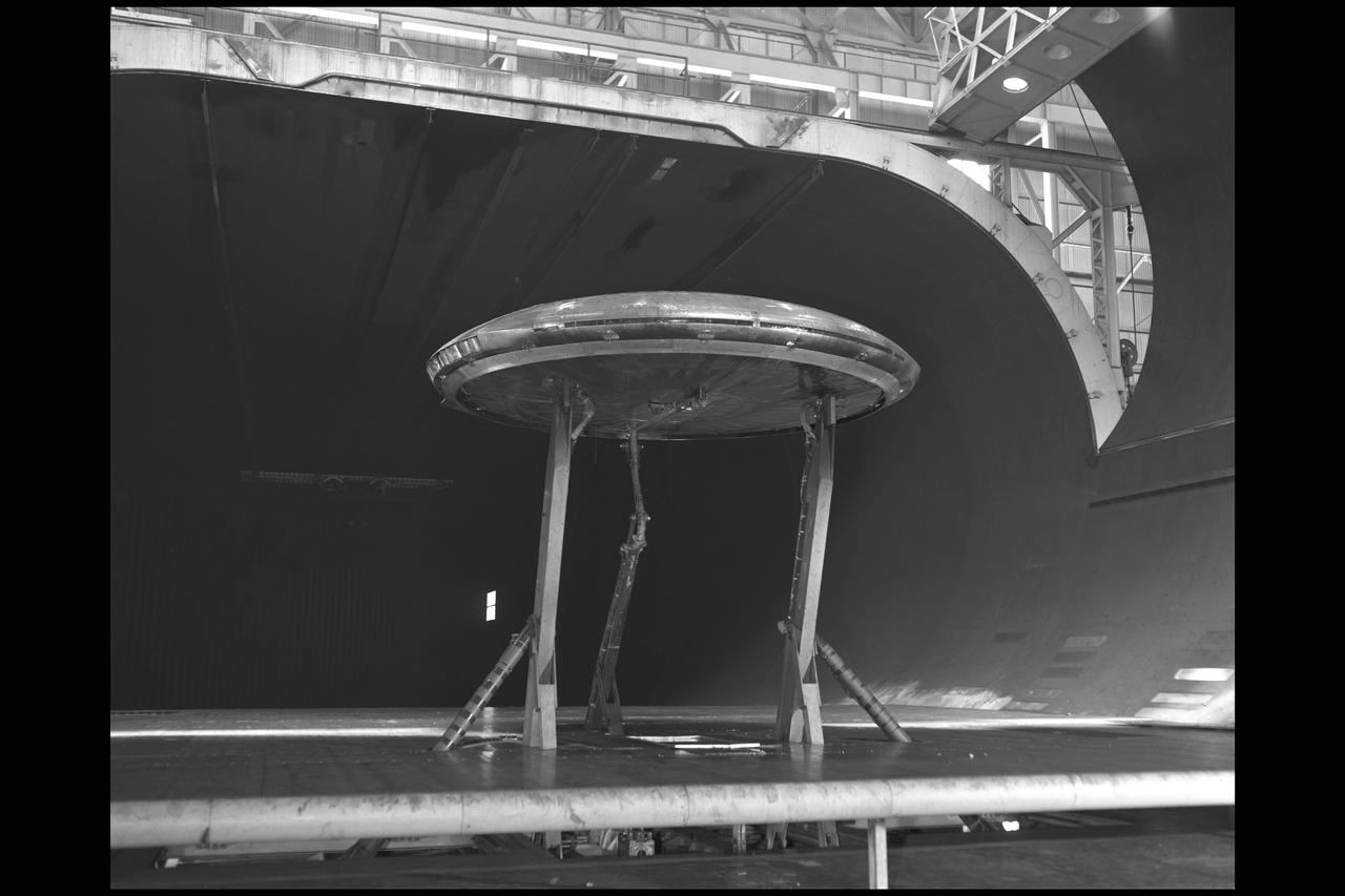
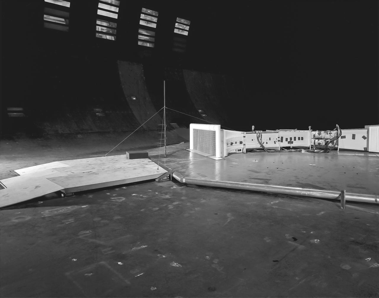
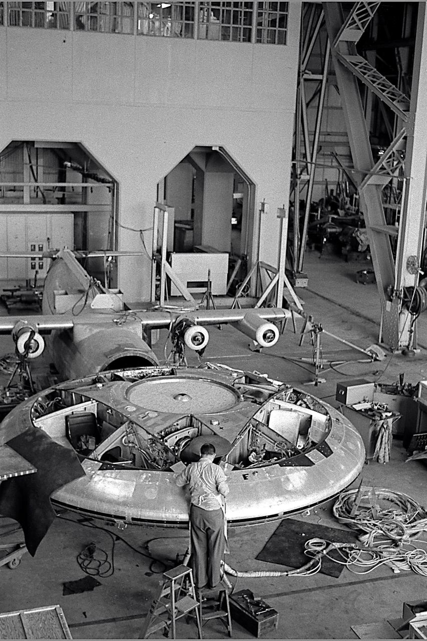
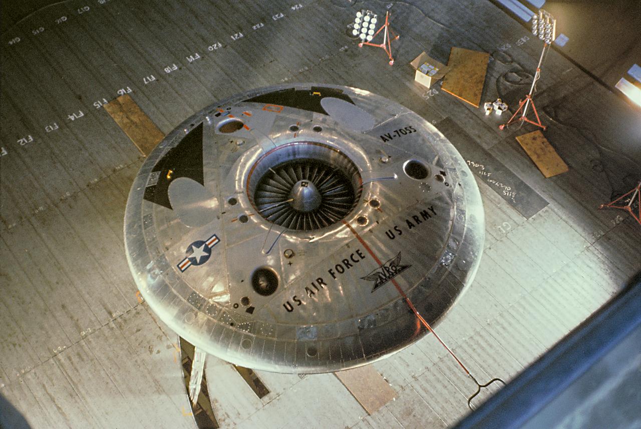
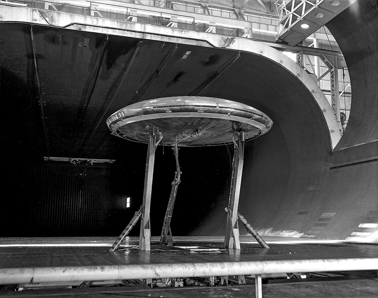
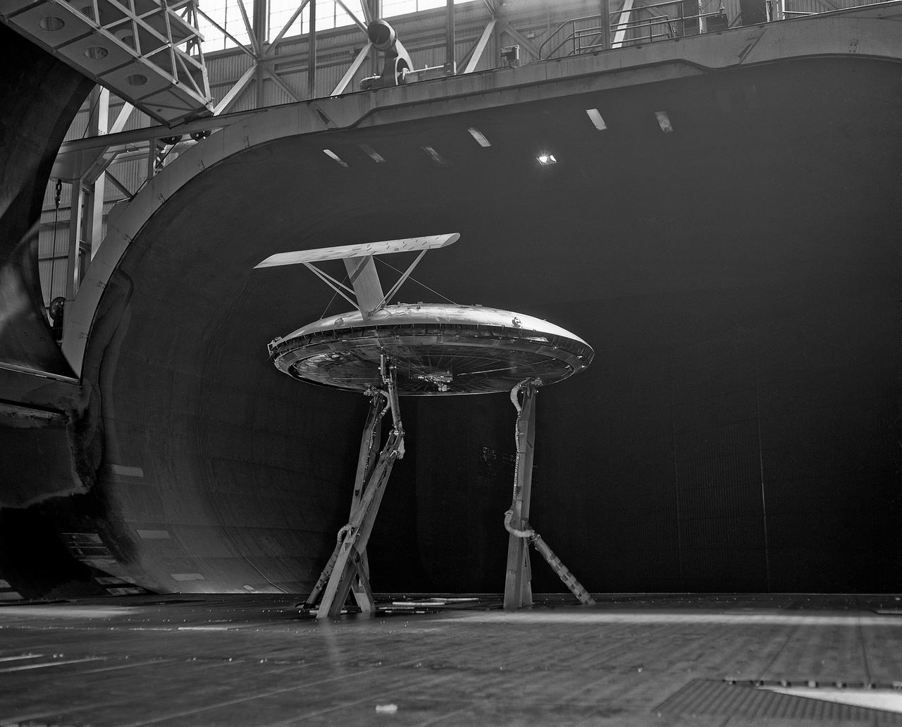
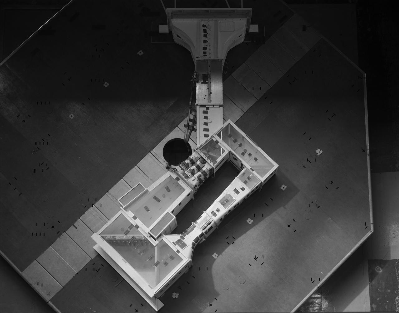
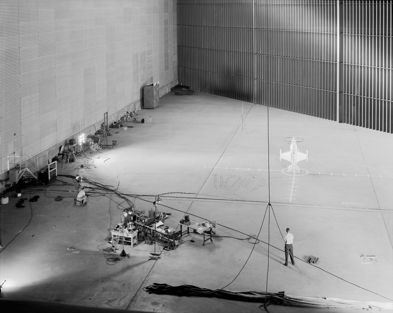
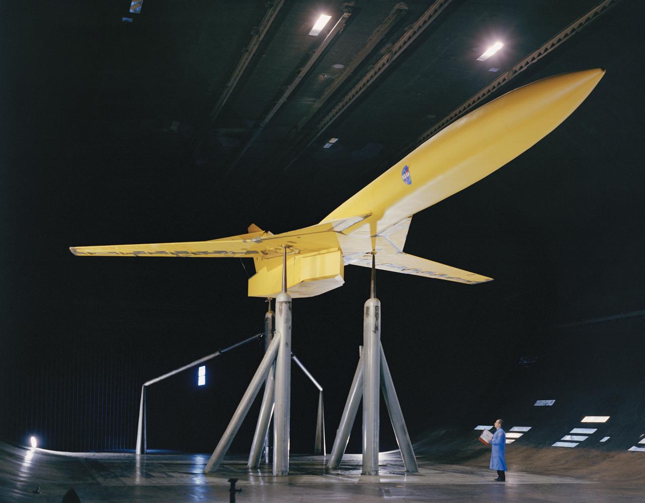
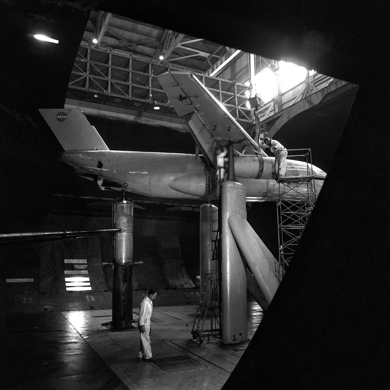
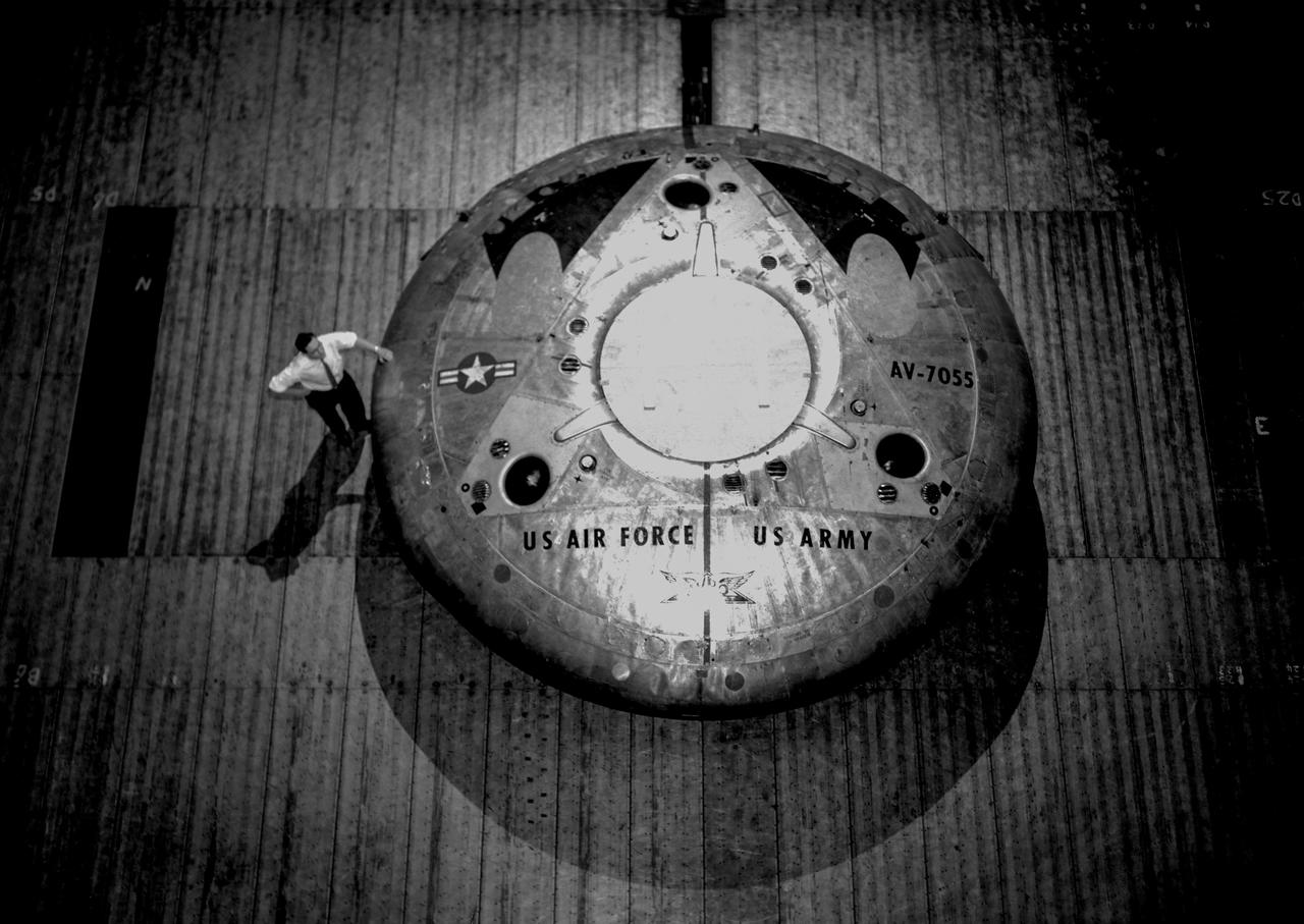
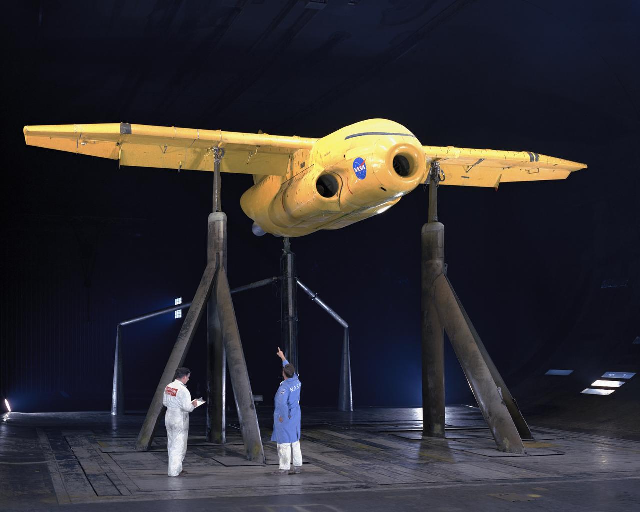
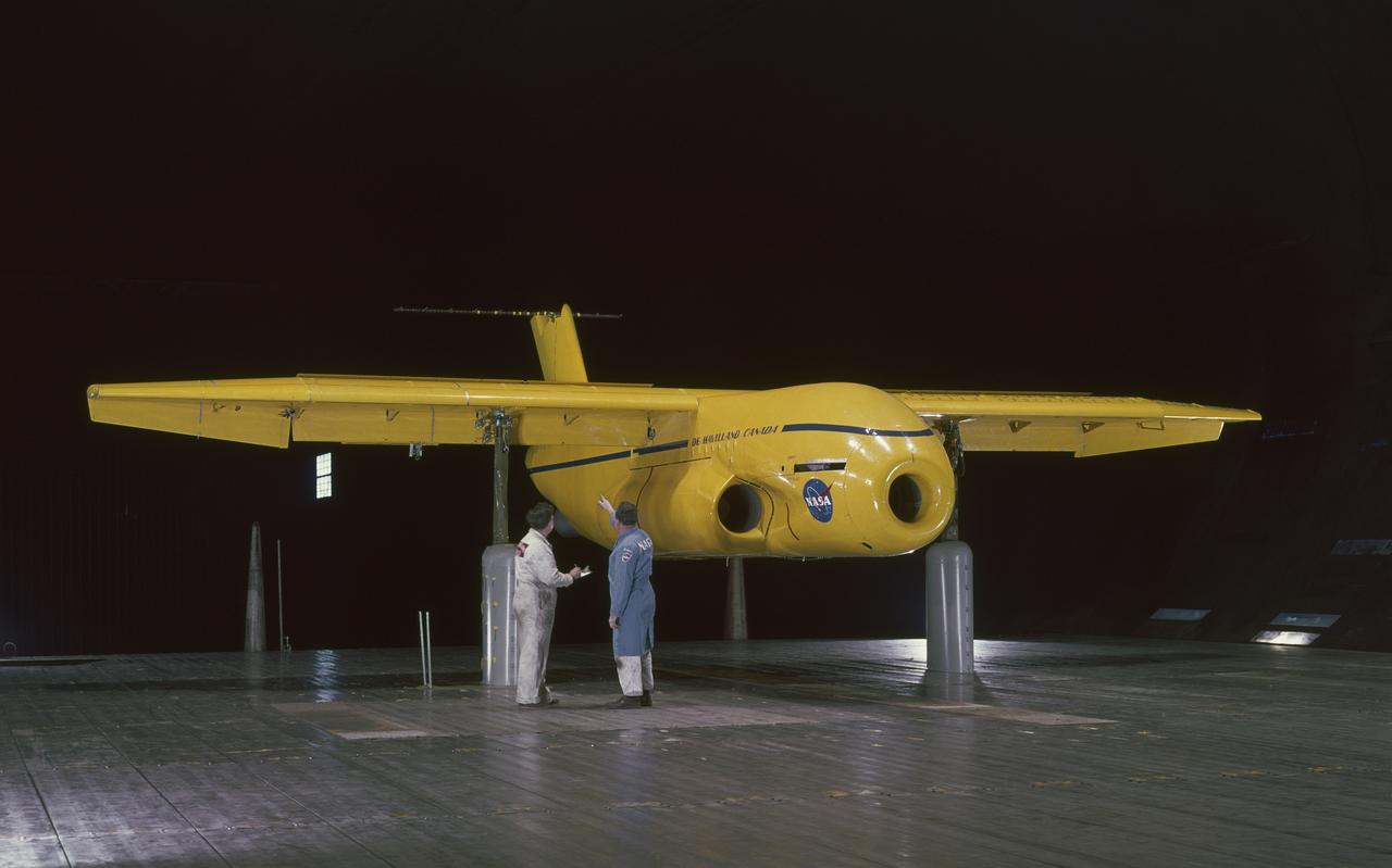
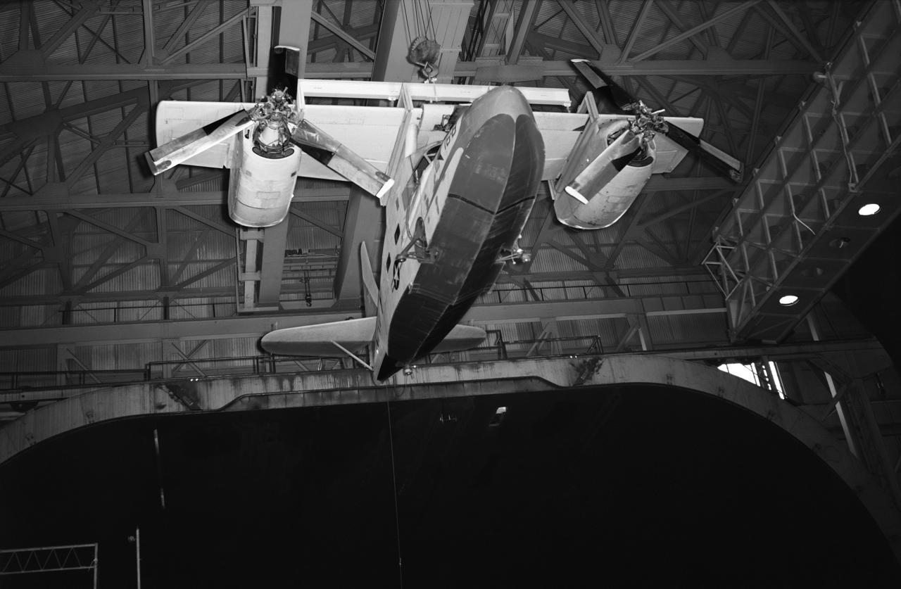
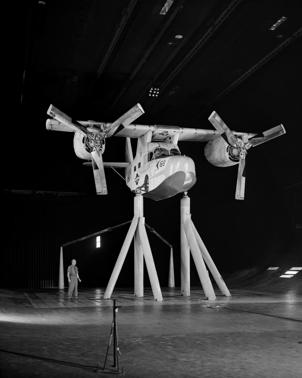
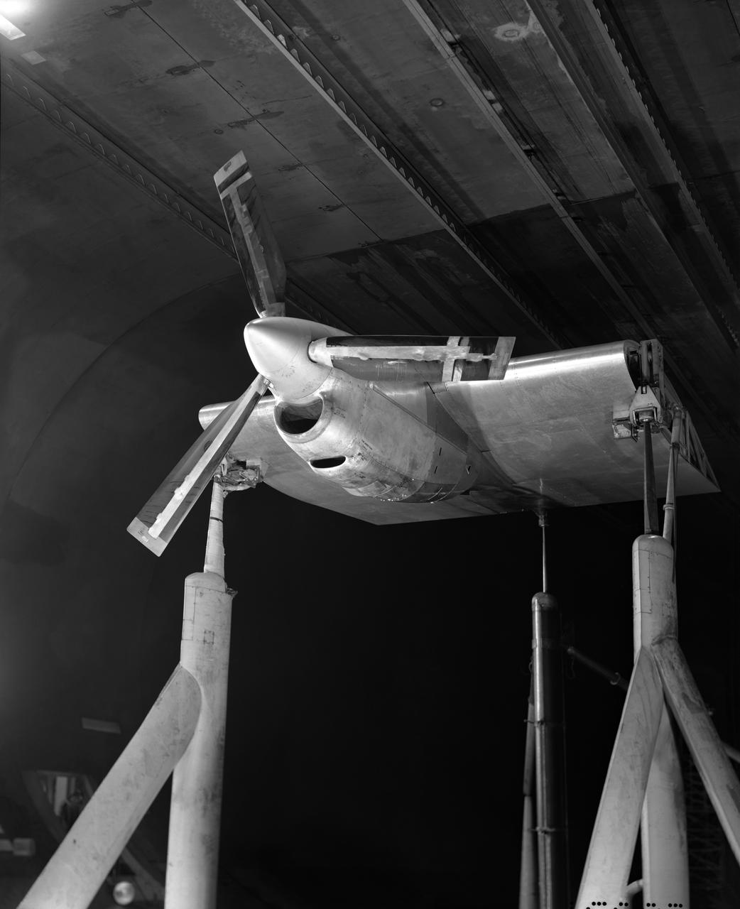
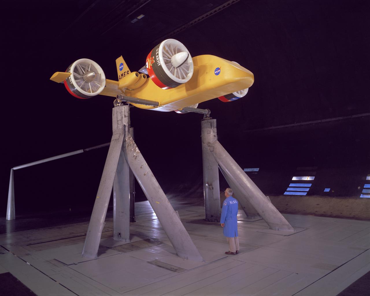
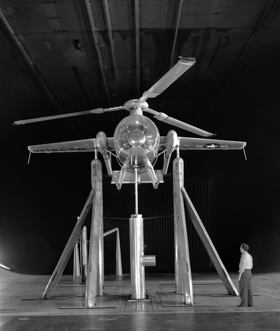
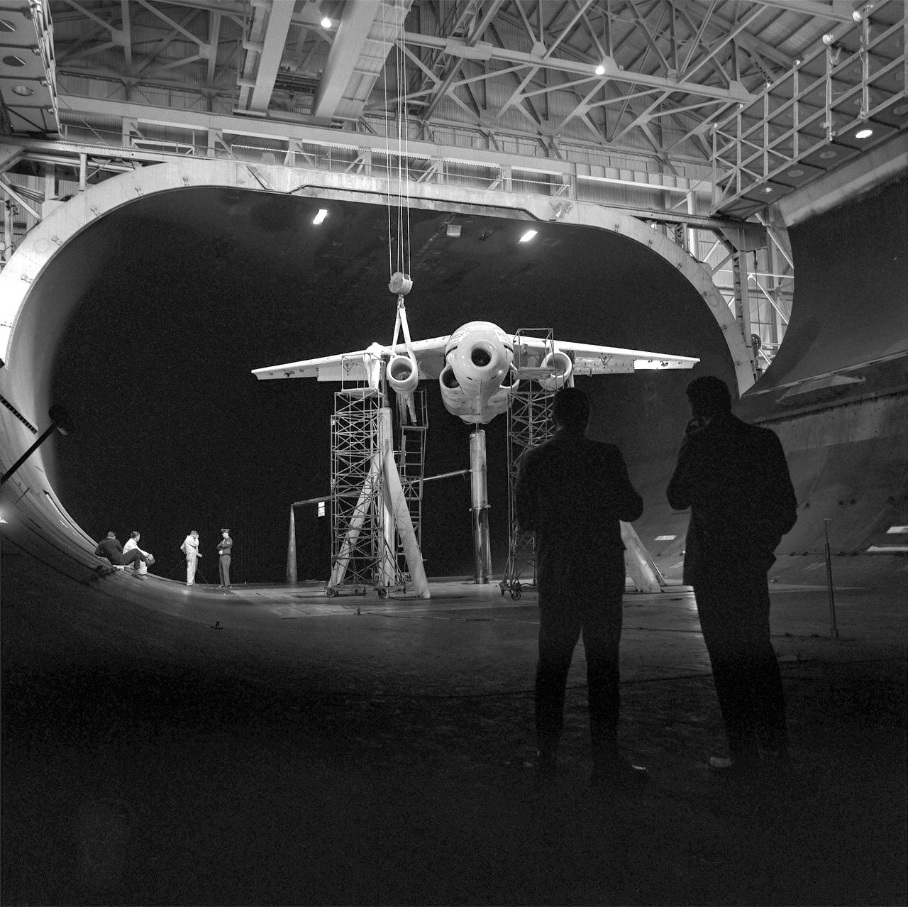
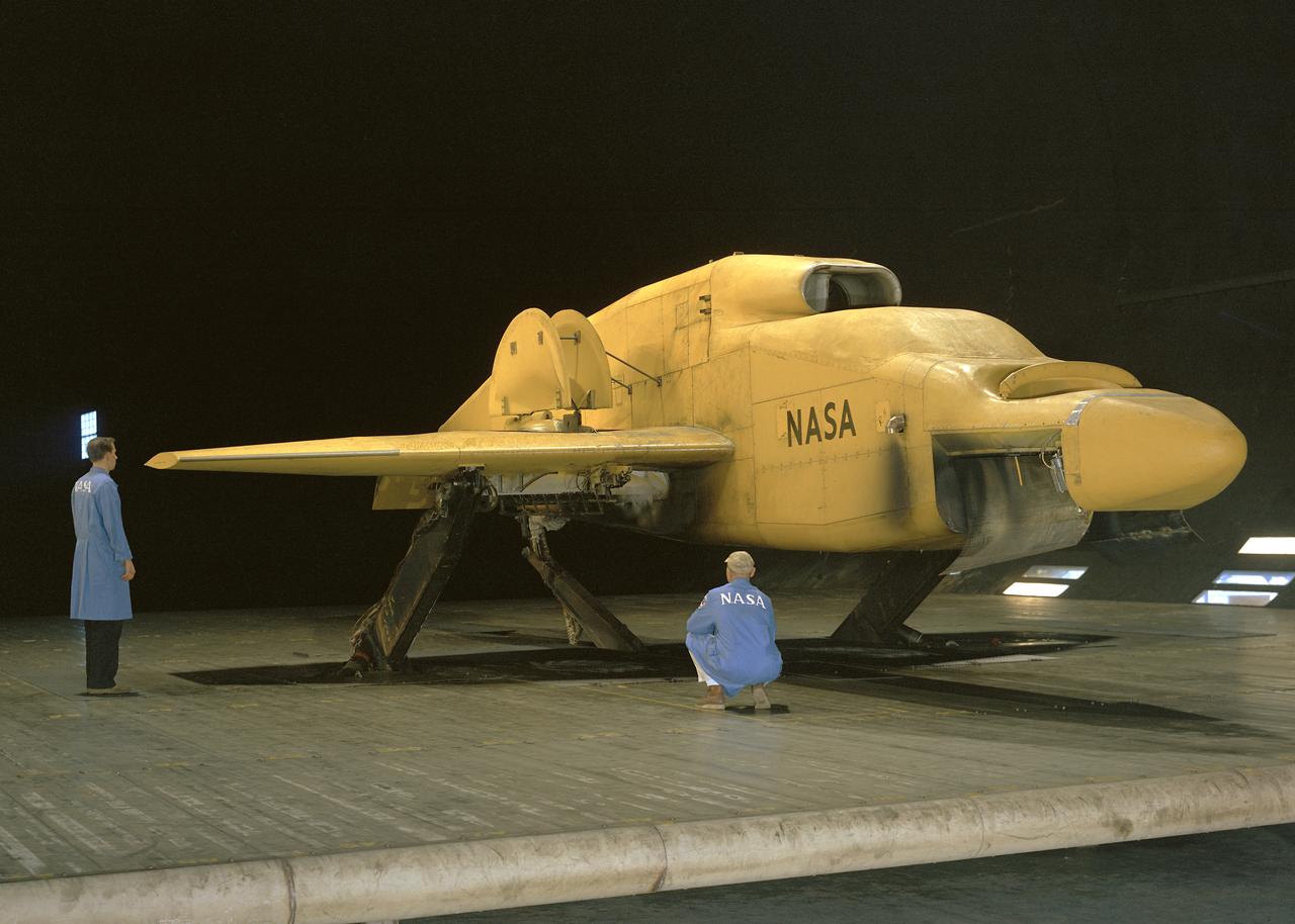
Avrocar Test in Ames 40x80 Foot Wind Tunnel.
Looking South from inside the diffuser of the 40x80 foot wind tunnel at NACA's Ames Research Center.  Construction began in late 1941, the mammoth construction task sorely taxing the resources of the new center. Two and a half years later, in dune 1944, the 40 x 80-foot full-scale tunnel went into operation.
Construction of the 40x80 Foot Wind Tunnel at Ames.
(Test 460) deHavilland Augmentor Wing 40x80 Foot Wind Tunnel.
deHavilland Augmentor Wing 40x80 Foot Wind Tunnel Test 460
Raised Floor Calibration Hardware for the Boundary Layer Ingesting Inlet Distortion Tolerant Fan tests to be performed in the 8' x 6' Supersonic Wind Tunnel at NASA Glenn Research Center.
8' x 6' Supersonic Wind Tunnel
(03/12/1976) 1/50 scale model of the 80x120 foot wind tunnel model (NFAC) in the test section of the 40x80 foot wind tunnel. Model mounted on a rotating ground board designed for this test, viewed from the west, oriented for North wind.
A76-0634. 1/50 Scale Model Of The 80X120 Foot Wind Tunnel Model (Nfac) In The Test Section Of The 40X80 Foot Wind Tunnel.
Rear view of the Avrocar with tail, mounted on variable height struts.  Overhead doors of the wind tunnel test section open.
AVROCAR Test in the NASA Ames 40x80 foot Wind Tunnel.
Langley Parawing 3/4 front view flying vertically in 40 x 80 wind tunnel.
Langley Parawing Flying Vertically in 40x80 Foot Wind Tunnel.
(03/12/1976) Overhead view of 1/50 scale model of the 80x120 foot wind tunnel model (NFAC) in the test section of the 40x80 wind tunnel at NASA Ames. Model mounted on a rotating ground board designed for this test.
1/50 Scale Model Of The 80X120 Foot Wind Tunnel Model (NFAC) In The Test Section Of The 40X80 Wind Tunnel At Nasa Ames.
3/4 front view from below of the Ryan FR-1 airplane mounted in the NACA Ames 40x80 foot wind tunnel. Production configuration.
Ryan FR-1 in NACA Ames 40x80 foot Wind Tunnel.
Investigation of High Lift and Stall Control on 45 deg. 3/4 front view Sweptback Cambered and Twisted Wing, in Ames 40x80 foot Wind Tunnel.
A-15209. High Lift and Stall Control in Ames 40x80 Foot Wind Tunnel.
3/4 front view of Fixed Wing SST - Lockheed SST on Ground Plane with leading edge flaps deflected in Ames 40x80 foot Wind Tunnel.
Fixed Wing Supersonic Transport in Ames 40x80 Foot Wind Tunnel.
Gliding parachute test in 40x80 foot Wind Tunnel, mounted on main strut flying horizontally.
Steerable Parachute for Apollo Vehicle in Ames 40x80 foot Wind Tunnel.
3/4 front view of Lockheed Rigid Rotor model in Ames 40x80 foot wind Tunnel.
Lockheed Rigid Rotor Model in Ames 40x80 Foot Wind Tunnel.
3/4 front view from below of Delta wing Model with Nose Inlet in Ames 40x80 foot wind tunnel.
Delta Wing Test Model in Ames 40x80 Foot Wind Tunnel.
Wide shot of 40x 80 wind tunnel settling chamber with Lockheed XFV-1 model.  Project engineer Mark Kelly (not shown). Remote controlled model flown in the settling chamber of the 40x80 wind tunnel. Electric motors in the model, controlled the counter-rotating propellers to test vertical takeoff. Test no. 71
Lockheed XFV-1 model in the 40x80 foot wind tunnel at NASA Ames Research Center
M-2 lifting body wind tunnel model with wind tunnel mechanic Chuck Greco.  Model mounted on special support designed for lifting body models.  Flaps and elevons visible.
M-2 Lifting Body, F.S.W.T. in Ames 40x80 Foot Wind Tunnel.
Front lower view of Gates Learjet in Ames 40x80 foot wind tunnel at high angel of attack.  Test was part of a deep stall study.
Lear Jet test in Ames 40x80 Foot Wind Tunnel.
3/4 rear view of the Ryan FR-1 airplane mounted in the NACA Ames 40x80 foot wind tunnel from below. Production configuration.
Ryan FR-1 in 40x80 foot Wind Tunnel from below.
(02/18/1964) Apollo 3 Parachute cluster, flown vertically in 40x80 wind tunnel.  Parachutes mounted on a control head with reels to vary the line lengths.
Steerable Parachute for Apollo Vehicle tested in Ames 40x80 foot Wind Tunnel..
Space Shuttle SSV Orbiter Model A100 0.36 Scale In 40x80 Foot Wind Tunnel. 3/4 lower rear view.
Space Shuttle SSV Orbiter Model In 40x80 Foot Wind Tunnel.
Looking West at three test section bents in place for the Ames 40 x 80 foot wind tunnel.  Concrete model scale support visible in the middle.
Construction of the Ring leading to the Test Section of the Ames 40x80 Foot Wind Tunnel.
F-14A fighter model lifted from the shop floor of the 40 x 80 foot wind tunnel.  3/4 scale
Grumman F-14A Airplane In Ames 40X80 Foot Wind Tunnel.
Truss-braced wind model installed in the Ames 11x11 Foot Wind Tunnel for testing as part of the Subsonic Ultra Green Aircraft Research Project (SUGAR)
ACD16-0013-013
Computers' at work in 16ft wind tunnel - calculating test data
Computers calculating data from teh Ames 16 Foot Wind Tunnel.
3/4 front view in Ames 40x80 foot Wind Tunnel investigation of the Lockheed T-33 modified for area-suction leading-edge and trailing edge flaps.
Northrop N-69 Missile in the Ames 40x80 foot Wind Tunnel.
Deep Stall Model in Ames 40x80 foot Wind Tunnel. 3/4 front view from below of swept wing jet transport with T-Tail and Aft Engins, with Art Morris.
Deep Stall Model in Ames 40x80 foot Wind Tunnel.
Wind Tunnel investigation of ducted fan though 180 deg angle of attack. 3/4 front view of Doak ducted fan, semi-span model with tufts.
Investigation of Ducted Fan in Ames 40x80 Foot Wind Tunnel.
Clark Y Airfoil. 3/4 front view of 8x48 foot Clark Y Airfoil mounted (inverted) in the 40x80 foot wind tunnel at NACA's Ames Research Center.
A Clark Y Airfoil, mounted in the 40x80 foot wind tunnel.
3/4 rear view from below of swept wing jet transport with T-Tail and Aft Engins, with Art Morris. Deep Stall Model in Ames 40x80 foot Wind Tunnel.
Deep Stall Model in Ames 40x80 foot Wind Tunnel.
One of the first helicopter tests in the 40 x 80 wind tunnel.  John McCloud, pictured, started helicopter work in the 40 x 80.  Test 150. Testing the effects of camber on rotor blades.
Rotor Blade Test in the NACA Ames 40x80 foot Wind Tunnel.
Vertol-76 Descent Test. Tilt Wing airplane prop rig at 80 deg. Angle of attack, in the 40x80 foot wind tunnel at NASA's Ames Research Center.
Vertical Prop and Wing in the Ames 40x80 foot wind tunnel.
Truss-Braced Wind Model installed in the Ames 11x11 Foot Wind Tunnel for testing. The Truss-Braced model is part of the Subsonic Ultra Green Aircraft Research Project (SUGAR)
ACD16-0013-026
Truss-braced wind model installed in the Ames 11x11 Foot Wind Tunnel for testing as part of the Subsonic Ultra Green Aircraft Research Project (SUGAR) Shown here with test engineer Greg Gatlin, Langley Research Center.
ACD16-0013-015
(11/12/1971) 3/4 rear view of swept 75% scale augmentor wing quest model being installed into the test section of the Ames 40x80 foot wind tunnel, overhead doors open.
Swept Augmentor Wing Model Installed in the Ames 40X80 Foot Wind Tunnel.
3/4 lower rear view of Controllable Twist Rotor (CTR) test of 4 blade helicopter model. Pictures with Ben Mandwyler Andy Lemnios, in 40x80 foot wind tunnel. Small flaps on rotor blades.
Controllable Twist Rotor in 40x80 Foot Wind Tunnel at Ames.
Forward overhead view of lift fan transport model, with two, of a possible six, high pressure ratio wing lift fans. Lift Fan Model In 40 X 80 Wind Tunnel; Test 40-347
Lift Fan Model In Ames 40 X 80 Wind Tunnel.
Supersonic transport model test in 40x80 foot wind tunnel, 3/4 overhead view of model in shop floor.  04/06/1961 R 975 T
Supersonic Transport Model in the shop of the Ames 40x80 Foot Wind Tunnel.
Looking south at the construction of the test section of the 40 x 80 foot wind tunnel.  4 parts of a test section bent seen in the  foreground. Airship rising in the background.
Construction of the Ring Section of the 40x80 Foot Wind Tunnel at NACA Ames.
3/4 view of model in cruise configuration with 25 deg. Sweep, AR=6.9. SCAT-16; Variable Sweep Model in 40x80 Wind Tunnel at NASA Ames.
SCAT-16; Variable Sweep Model in 40x80 Wind Tunnel at NASA Ames.
First airplane tested in the ames 40 x 80 foot wind tunnel. Douglas XSB2D-1 (Destroyer)  hanging from overhead crane above the test section.
Mounting Douglas XSB2D-1 Airplane In 40x80 Foot Wind Tunnel.
(03/12/1943) Aerial view of the site from the 40x80 wind tunnel At NASA Ames Research Center. Site includes the 16 foot and 7x10 wind tunnels in the background.  Building 200 also under construction.  Framing for the drive fans of the 40x80 in scene.
Aerial View Of The Site From The 40x80 Foot Wind Tunnel At Nasa Ames Research Center.
Avrocar Annular Jet VTOL Airplane in Ames 40x80 foot Wind Tunnel.
Overhead View of Avrocar Annular Jet VTOL Airplane in Ames 40x80 foot Wind Tunnel.
Drag studies for Full Scale wind tunnel test of Grumman YAO-1 airplane, 3/4 front view with propellers on
Grumman YAO-1 airplane mounted in the 40x80 foot wind tunnel at Ames.
Computers' at work in 16ft wind tunnel - calculating test data - reading manometer board
Computers reading from the Manometer Board of the 16 Foot Wind Tunnel.
Bell V/STOL X-14 airplane mounted at 90 degrees yaw in 40x80 foot wind tunnel.
Bell VSTOL X-14 Airplane in Ames 40x80 foot Wind Tunnel.
(Oct. 27 1976) Controllable Twist Rotor, 40x80 Foot Wind Tunnel at Ames Research Center, model With John Bolt.
Controllable Twist Rotor, 40x80 Foot Wind Tunnel at Ames Research Center.
The 10- by 10-Foot Supersonic Wind Tunnel (10×10) is the largest and fastest wind tunnel facility at NASA’s Glenn Research Center and is specifically designed to test supersonic propulsion components from inlets and nozzles to full-scale jet and rocket engines.
10 x 10 Wind Tunnel
3/4 front view of XV-4A Hummingbird VTOL Research Vehicle in Ames 40x80 wind tunnel with Tom Wills in Photo.
XV-4A Hummingbird VTOL Research Vehicle in Ames 40x80 Wind Tunnel.
de Havilland augmenter wing model 3/4 front view in 40 x 80 wind tunnel. JOHN CONWAY, ALAN WHEELBAND
de Havilland Augmenter Wing Model in Ames 40x80 foot Wind Tunnel.
Front View of -45 deg. Forward swept wing with inboard split flaps deflected 60 deg. In NACA Ames 40x80 foot Wind Tunnel.
Swept wing with inboard split flaps in Ames 40x80 foot Wind Tunnel.
3/4 lower front view of Controllable Twist Rotor (CTR) test of 4 blade helicopter model.  Pictures with Ben Mandwyler Andy Lemnios, John McCloud (wheel chair), in 40x80 foot wind tunnel.  Small flaps on rotor blades.
Controllable Twist Rotor in 40x80 Foot Wind Tunnel at Ames.
Concrete frame enclosing the fan drive bents of the 40x80 foot wind tunnel at ames.  Once installed, six 40-foot-diameter fans, each powered by a 6000-horsepower electric motor maintained airflow at 230 mph or less (these are still tornado velocities).
Construction of the Fan Drive Enclosure of the 40x80 Foot Wind Tunnel at Ames.
Test No. 175  Kaman K-16 in 40x80 Foot Wind Tunnel at Ames Research Center.  Kaman K-16B was an experimental tilt wing aircraft, it used the fuselage of a JRF-5 and was powered by two General Electric YT58-GE-2A engines.
Kaman K-16 in 40x80 Foot Wind Tunnel at Ames Research Center.
Aerial view looking North West of the nearly completed 40 x 80 foot wind tunnel.  Drive and test section exposed. The facility covered 8 acres, and the air circuit was just over 1/2 mile long (2700 feet).
Aerial View of the Nearly Completed 40x80 Foot Wind Tunnel at Ames
Instrumentation in 16 Foot Wind Tunnel manometer boards
Instrumentation in 16 Foot Wind Tunnel
3/4 front view of model without nacelles on regular struts. Generalized Subsonic Jet Transport model with leading edge and trailing edge blowing BLC in the 40x80 foot wind tunnel at NASA Ames.
Generalized Subsonic Jet Transport in 40x80 Foot Wind Tunnel at NASA Ames.
3/4 front view, a=0. de Havilland Augmenter Wing Model, High Lift System in Ames 40x80 Foot Wind Tunnel. Cecil McDonald and Al Wheelband in picture.
Augmenter Wing High Lift System in Ames 40x80 Foot Wind Tunnel.
Computers' at work in 16ft wind tunnel - calculating test data
Computers processing data from the 16 Foot Wind Tunnel at Ames Research Center.
Testing the wing boundary layer control of the A3D in the 40 x 80 wind tunnel.  Boundary layer control was added to increase the lift of the wing for aircraft carrier take off and landing.
Douglas XA3D-1 #413 Airplane mounted in Ames 40x80 foot Wind Tunnel.
3/4 front view of Lockheed AH-56A (Cheyenne) Helicopter in Ames 40x80 Foot Wind Tunnel
Lockheed AH-56A (Cheyenne) Helicopter in Ames 40x80 Foot Wind Tunnel
Test No. 175  Kaman K-16 in 40x80 Foot Wind Tunnel at Ames Research Center. Pictured with two Kaman employees.  3/4 Front view of Airplane.  Kaman K-16B was an experimental tilt wing aircraft, it used the fuselage of a JRF-5 and was powered by two General Electric YT58-GE-2A engines.
Kaman K-16 in 40x80 Foot Wind Tunnel at Ames Research Center.
Test No. 175  Kaman K-16 being lowered into the 40x80 foot wind tunnel at NASA's Ames Research Center, viewed from the front. Kaman K-16B was an experimental tilt wing aircraft, it used the fuselage of a JRF-5 and was powered by two General Electric YT58-GE-2A engines.
Kaman K-16 in 40x80 Foot Wind Tunnel at Ames Research Center.
Test of Lockheed YC-130 Turbo-Propeller Installation in Ames 40x80 Foot Wind Tunnel. 3/4 front view from below.
Tests of Lockheed YC-130 Turbo-Propeller Installation in Ames 40x80 Foot Wind Tunnel.
3/4 front view of Douglas F5D Skylancer modified to "ogee" platform inlet plug installed in Ames 40x80 foot wind tunnel.
F-5D Airplane modified to "ogee" platform inlet plug installed in Ames 40x80 foot wind tunnel.
Installation of 1/3 scale model of space shuttle orbiter into the test section of the Ames 40x80 foot wind tunnel with overhead doors open.
Installation of 1/3 scale model of Space Shuttle Orbiter into 40x80 Foot Wind Tunnel.
Installation Photos, 3/4 front view from below. F-111B in Ames 40x80 Foot Wind Tunnel.  The General Dynamics/Grumman F-111B was a long-range carrier-based interceptor aircraft that was planned to be a follow-on to the F-4 Phantom II. The F-111B was developed in the 1960s by General Dynamics in conjunction with Grumman for the United States Navy (USN) as part of the joint Tactical Fighter Experimental (TFX) with the United States Air Force (USAF) to produce a common fighter for the services that could perform a variety of missions. It incorporated innovations such as variable-geometry wings, afterburning turbofan engines, and a long-range radar and missile weapons system.
F-111B in Ames 40x80 Foot Wind Tunnel.
3/4 front view from below, showing Pods and Fan Rotating. March A. Zeiger standing in front. Tandem Dual Ducted Fan V/STOL Model in Ames 40x80 foot Wind Tunnel
Tandem Dual Ducted Fan V/STOL Model in Ames 40x80 foot Wind Tunnel.
Low Speed investigation of a supersonic transport model in the 40x80 Wind Tunnel.  03/01/1961  R 975 T  Zero angel of attack. Supersonic transport with delta wing and delta conard. 3/4 front view.
Low Speed Investigation of a Supersonic Transport Model in the 40x80 Wind Tunnel at NASA Ames.
3/4 front view of M-1-L inflatable recovery able lifting body model in Ames 40x80 foot wind tunnel. Mechanic, Ray Schmorance included in picture.
M-1-L Inflatable Recovery able Lifting Body Model in Ames 40x80 foot Wind Tunnel.
Vanguard 2C vertical take-off and landing (VTOL) airplane, wind tunnel test. Front view from below, model 14 1/2 feet high disk off. Nasa Ames engineer Ralph Maki in photo.  Variable height struts and ground plane, low pressure ratio, fan in wing.  02/01/1960.
Vanguard 2C VTOL Airplane Tested in the Ames 40x80 Foot Wind Tunnel.
Long Range Laser Velocimeter in 40x80x120 Foot Wind Tunnel at NASA Ames. For use in NFAC.
Test section of the Ames 40 x 80 foot wind tunnel with the overhead doors open.  XSB2D-1 airplane being lowered onto the struts by the overhead crane. Mechanics and engineers on orchard ladders aligning the model with ball sockets on the struts. The Douglas BTD Destroyer was an American dive/ torpedo bomber developed for the United States Navy during World War II.
Installation of the Douglas XSB2D-1 in the Test Section of the 40x80 Foot Wind Tunnel at Ames.
Here you see the X-59 scaled model inside the JAXA supersonic wind tunnel during critical tests related to sound predictions.
X-59 Model Tested in Japanese Supersonic Wind Tunnel
North American F-100-F airplane, equipped with thrust reversers, full scale wind tunnel test. 3/4 front view of F-100-F airplane with North American Aviation thrust reverser. On standard 40x80 struts landing gear down. Mark Kelly, branch chief in photo.
North American Aviation F-100 in the Ames 40x80 Foot Wind Tunnel.
Lockheed XFV-1 model. Project engineer Mark Kelly (not shown). Remote controlled model flown in the settling chamber of the 40x80 wind tunnel. Electric motors in the model, controlled the counter-rotating propellers to test vertical takeoff. Test no. 71
Lockheed XFV-1 model in the 40x80 foot Wind Tunnel at NASA Ames Research Center.
Lockheed XH-51 Experimental Rigid Rotors, no hinges, in Ames 40x80 foot wind tunnel. John McCloud (left sitting) Jack Rabbot (Right).
Lockheed XH-51 Helicopter with Experimental Rigid Rotors in the 40x80 Foot Wind Tunnel at NASA Ames.
Foreword, front view of McDonnell Model XV-1 Convertiplane in the Ames 40x80 Foot Wind Tunnel.  The McDonnell XV-1 was an experimental compound gyroplane developed for a joint research program between the United States Air Force and the United States Army to explore technologies to develop an aircraft that could take off and land like a helicopter but fly at faster airspeeds, similar to a conventional airplane. The XV-1 would reach a speed of 200 mph (322 km/h), faster than any previous rotorcraft, but the program was terminated due to the tip-jet noise and complexity of the technology which gave only a modest gain in performance.
McDonnell Model XV-1 Convertiplane in the Ames 40x80 Foot Wind Tunnel.
Circa 1920's LANGLEY 5 FT. ATMOSPHERIC WIND TUNNEL 'EARLY WIND TUNNEL'.  Historical Photographs.
ARC-1920-A-30791-49
Parametric Inlet Model in 10x10 Wind Tunnel
GRC-2004-C-00378
(11/12/1971) 3/4 Scale swept augmentor wing Quest model being installed into the test section of the ames 40 x 80 foot wind tunnel, overhead doors open.
A71-8290. Swept Augmentor Wing Model Being Installed Into The Test Section Of The Ames 40 X 80 Foot Wind Tunnel.
JERRIE COBB - PILOT - TESTING GIMBAL RIG IN THE ALTITUDE WIND TUNNEL, AWT
2.8% Ares I Acoustic Reentry Wind Tunnel Model in Ames 9X7ft Supersonic Wind Tunnel test-97-0193; model flying backwards in tunnel
ARC-2008-ACD08-0266-019
2.8% Ares I Acoustic Reentry Wind Tunnel Model in Ames 9X7ft Supersonic Wind Tunnel test-97-0193; model flying backwards in tunnel
ARC-2008-ACD08-0266-018
2.8% Ares I Acoustic Reentry Wind Tunnel Model in Ames 9X7ft Supersonic Wind Tunnel test-97-0193; model flying backwards in tunnel
ARC-2008-ACD08-0266-020
14_foot wind tunnel with call outs
ARC-2000-A-20621
The flexwall section of NASA Glenn’s 10x10 supersonic wind tunnel is made up of two movable flexible steel sidewalls. These powerful hydraulic jacks move the walls in and out to control supersonic air speeds in the test section between Mach 2.0 and 3.5.
10' x 10' Supersonic Wind Tunnel Flexwall
3/4 front view VZ-11 ground test - variable height struts. Engines of the VZ-11 are a pair of General Electric J85-5 turbojets, mounted in high in the centre fuselage, well away from fan disturbance. Designed in the Ames 40x80 foot wind tunnel.
GE Fan in Wing VZ-11 VTOL airplane in Ames 40x80 Foot Wind Tunnel.
APOLLO STABILITY TEST IN THE 8X6 FOOT WIND TUNNEL - MODEL IS SHOWN WITH MODULE TOWER AND CANARDS
APOLLO STABILITY TEST IN THE 8X6 FOOT WIND TUNNEL - MODEL IS SHO
N-227 Wind Tunnel Data Control Room: Hardware
ARC-1985-AC85-0433-6
N-227 Wind Tunnel Data Control Room: Hardware
ARC-1985-AC85-0433-7
N-227 Wind Tunnel Data Control Room: Hardware
ARC-1985-AC85-0433-2