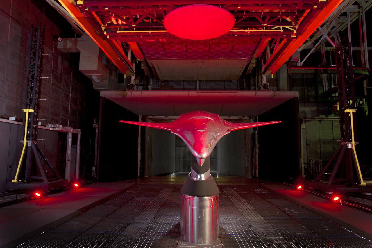
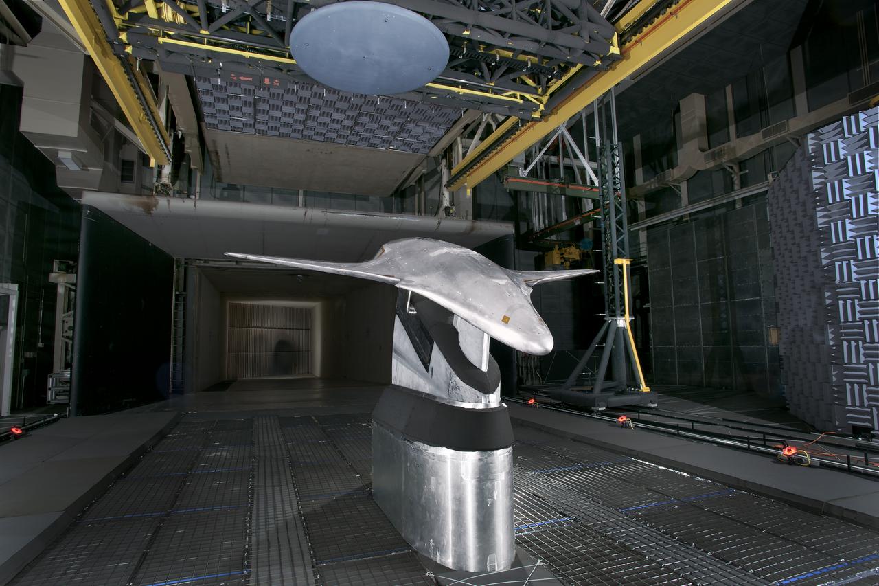
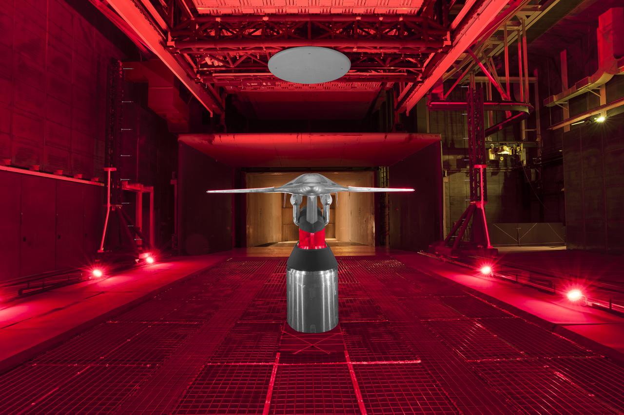
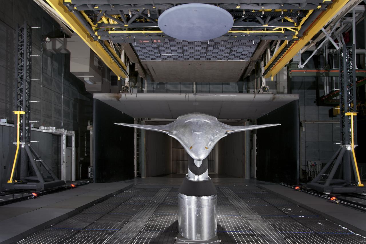
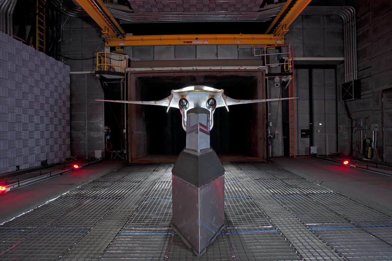
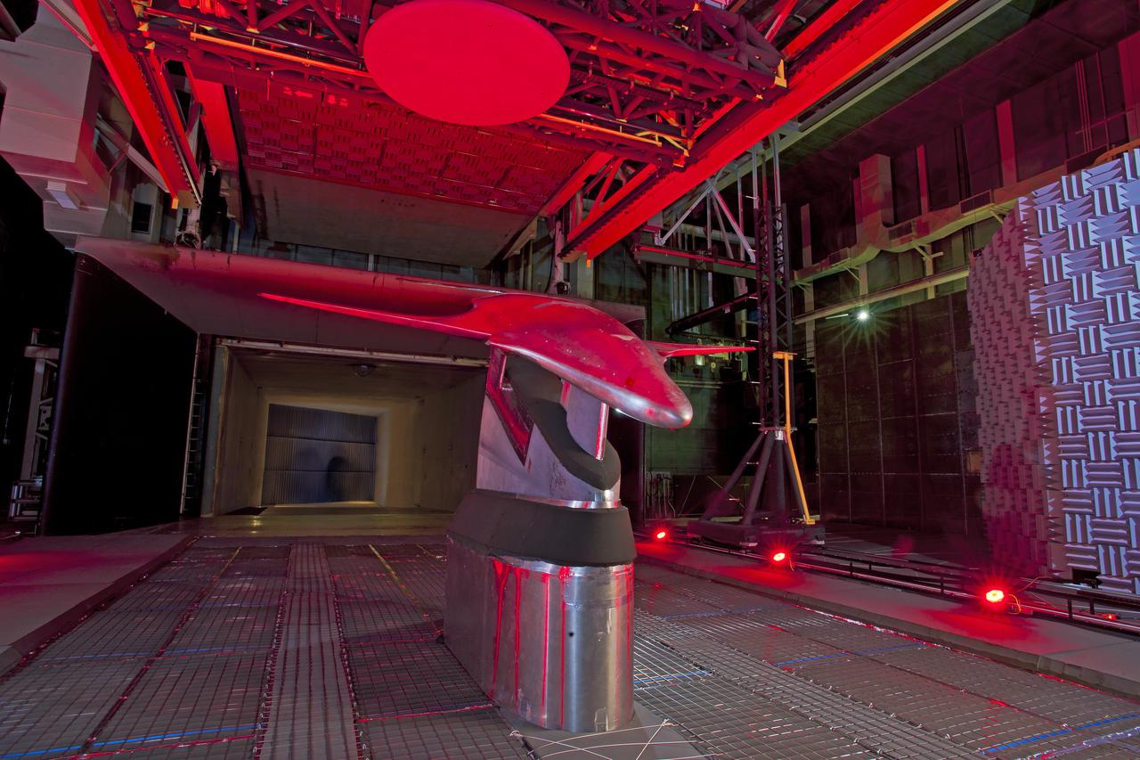
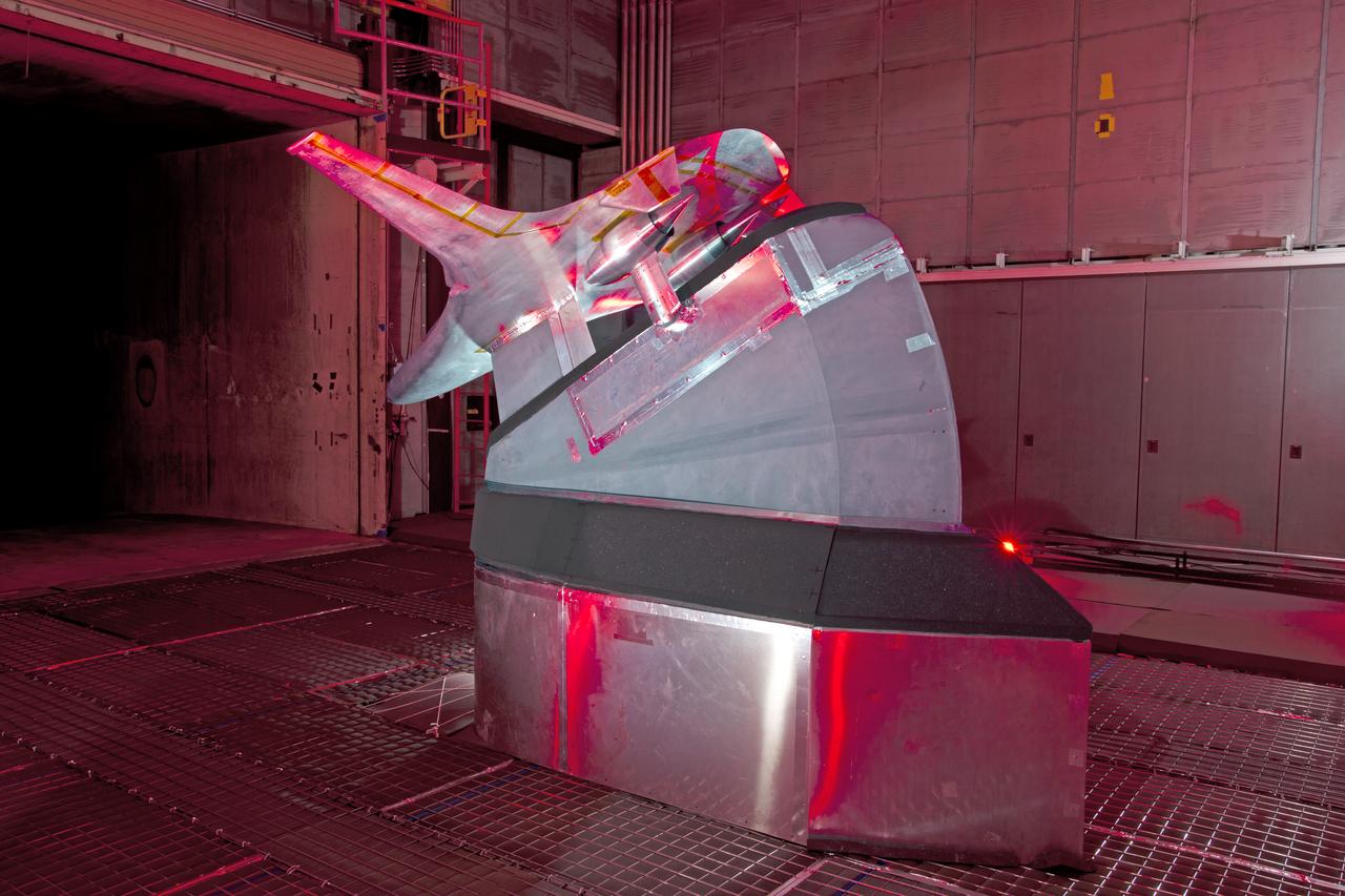
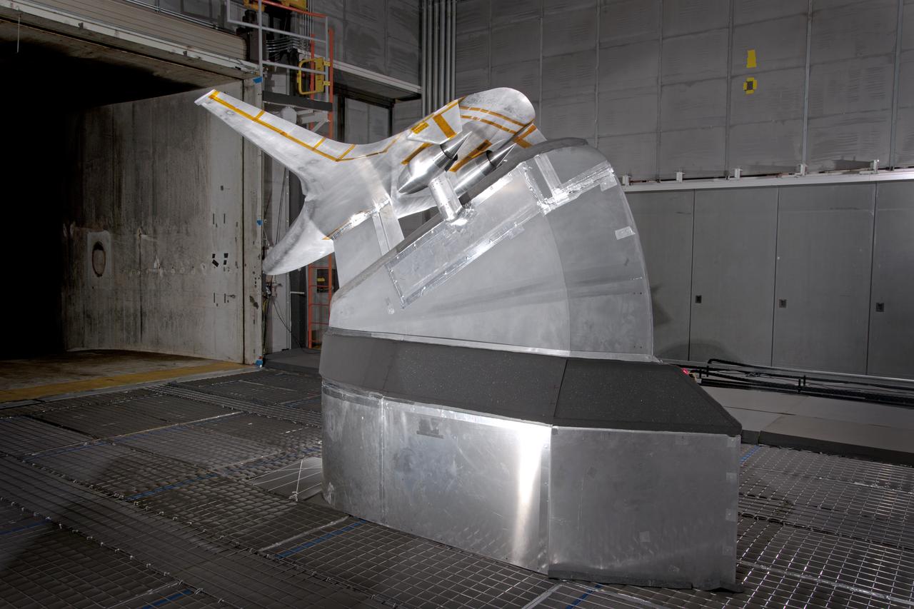
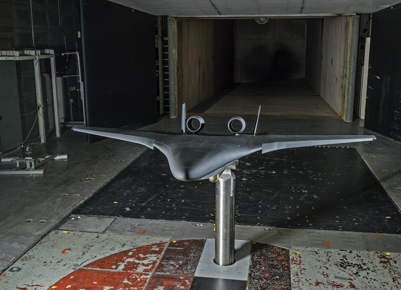
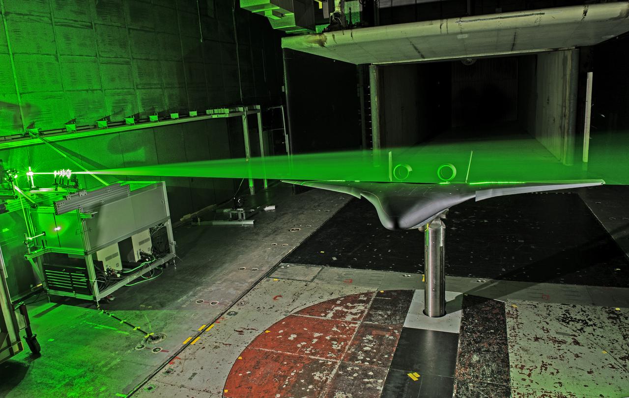
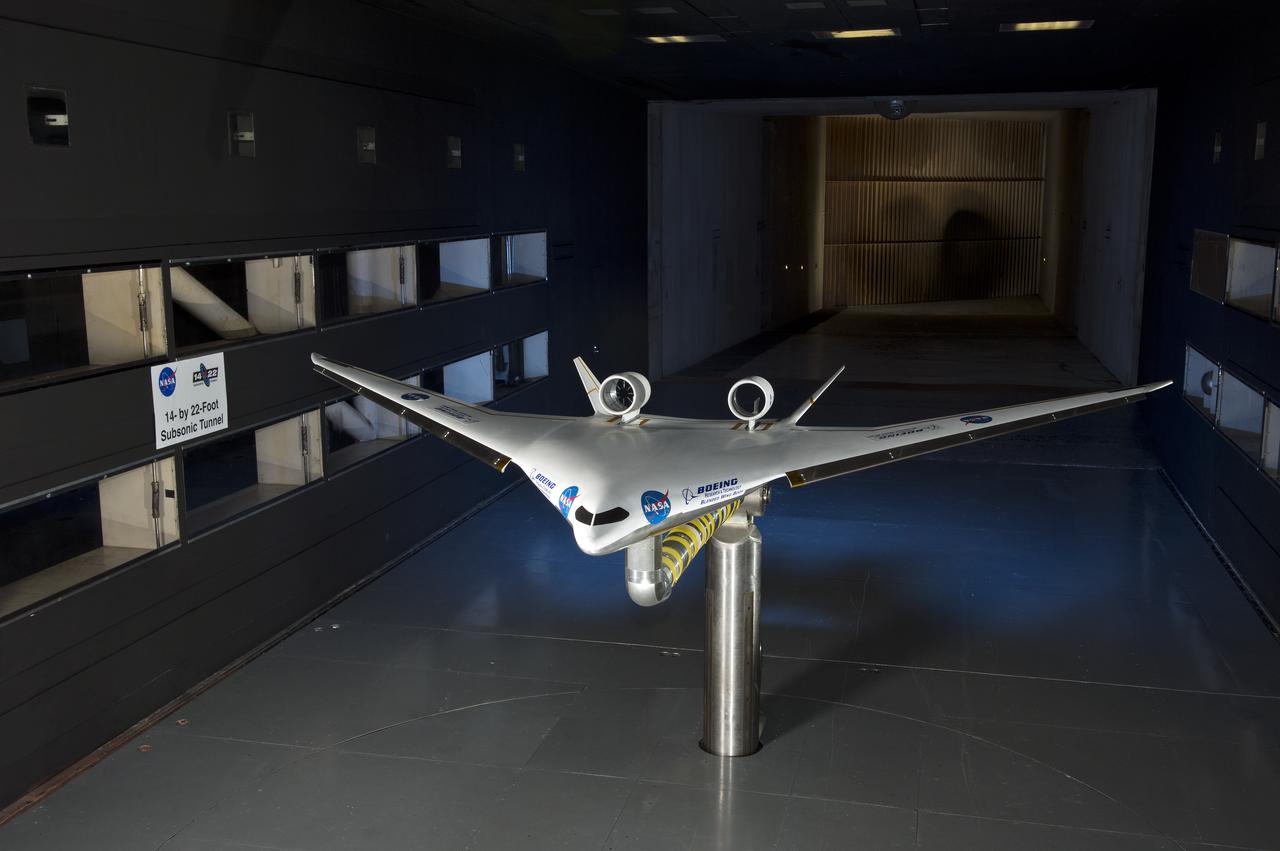
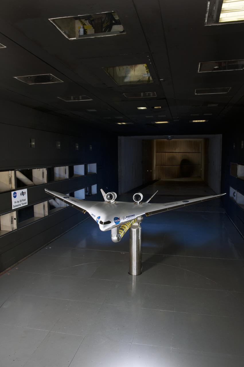
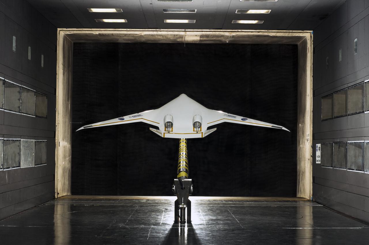
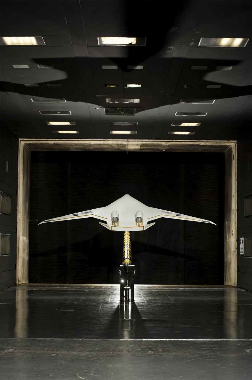
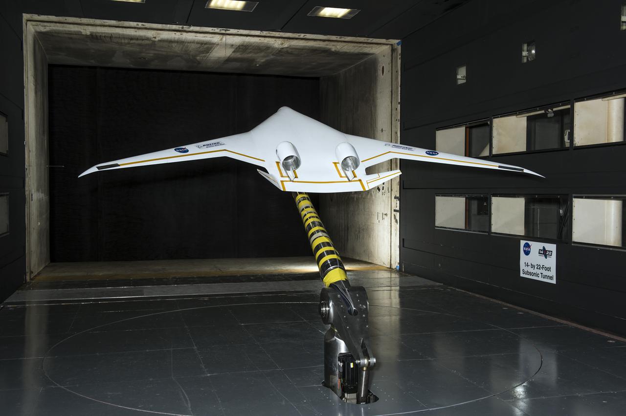
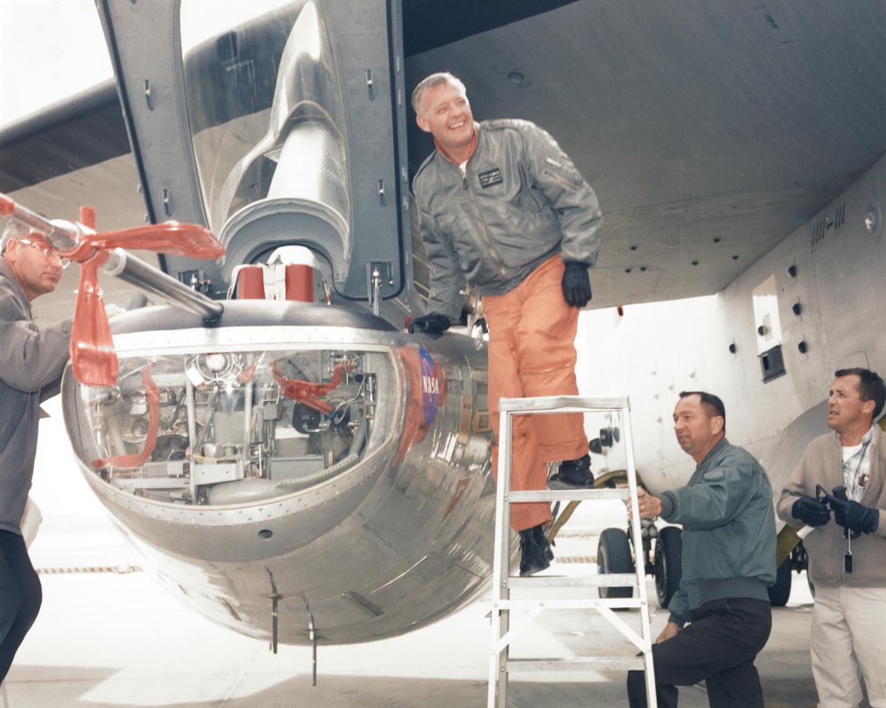
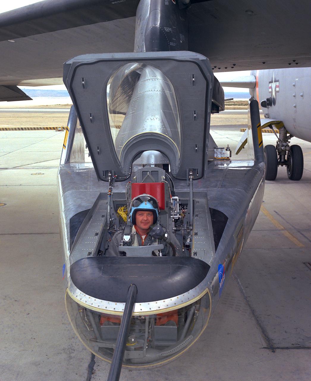
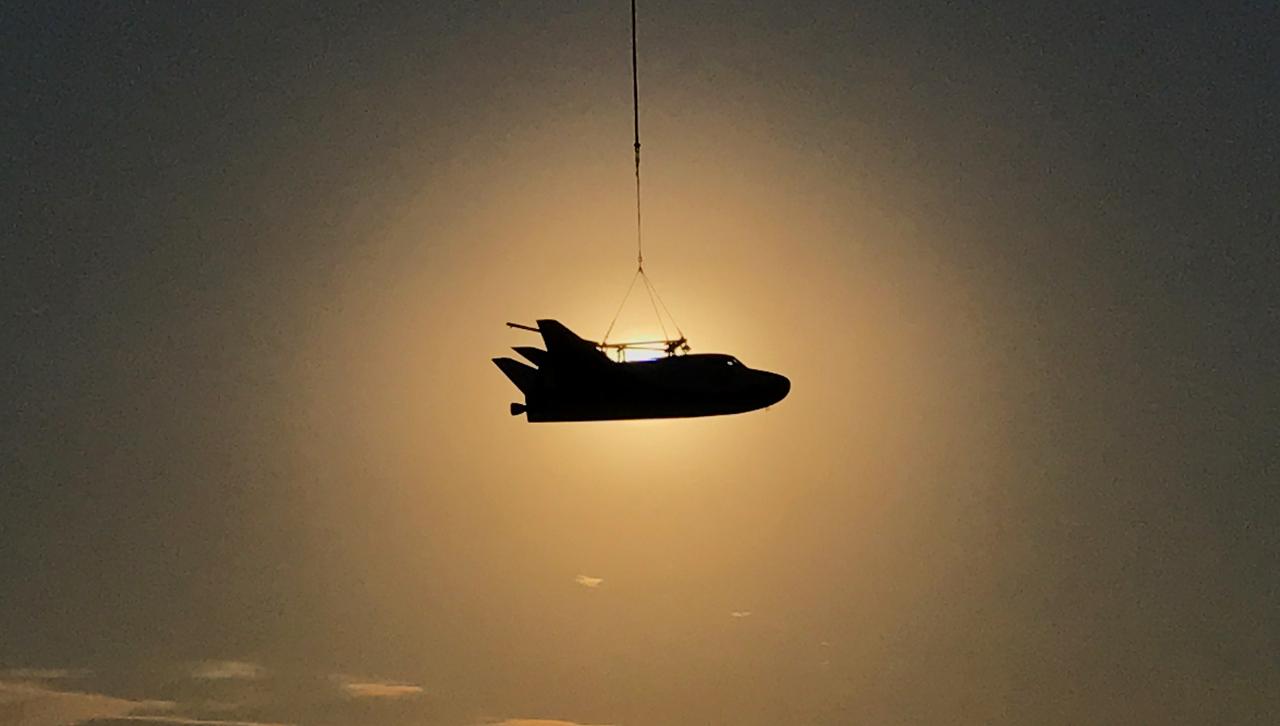
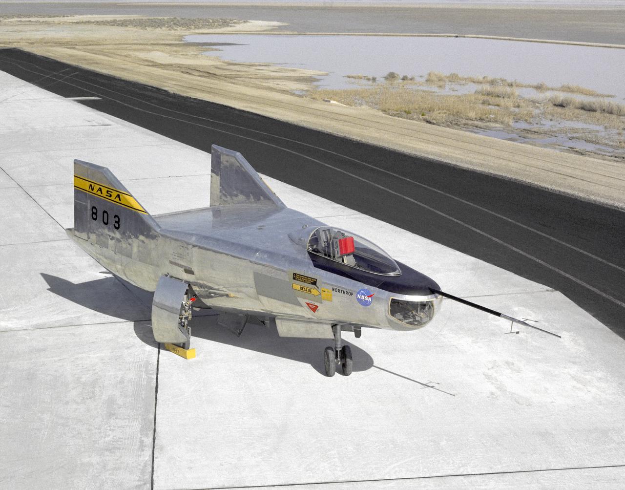
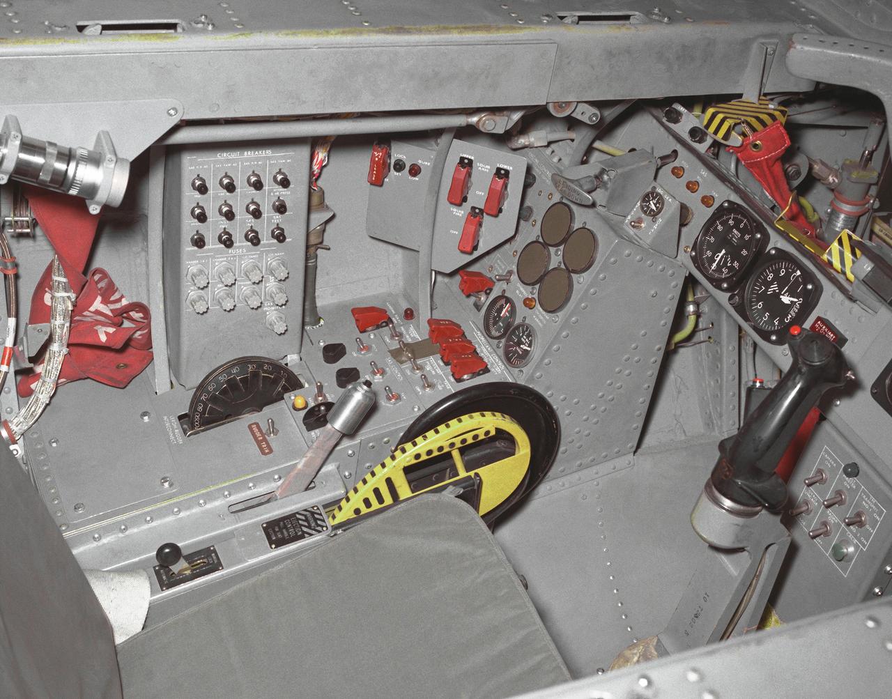
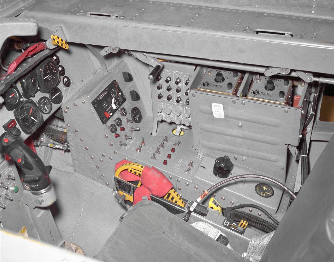
(HWB) Hybrid Wing Body Aerodynamic Test in 14x22 12.3 Foot Span HWB Model as tested in the 14x22 Foot Subsonic Tennel Aerodynamic Test
(HWB) Hybrid Wing Body Aerodynamic Test in 14x22
(HWB) Hybrid Wing Body Aerodynamic Test in 14x22 12.3 Foot Span HWB Model as tested in the 14x22 Foot Subsonic Tennel Aerodynamic Test
(HWB) Hybrid Wing Body Aerodynamic Test in 14x22
(HWB) Hybrid Wing Body Aerodynamic Test in 14x22 12.3 Foot Span HWB Model as tested in the 14x22 Foot Subsonic Tennel Aerodynamic Test
(HWB) Hybrid Wing Body Aerodynamic Test in 14x22
(HWB) Hybrid Wing Body Aerodynamic Test in 14x22 12.3 Foot Span HWB Model as tested in the 14x22 Foot Subsonic Tennel Aerodynamic Test
(HWB) Hybrid Wing Body Aerodynamic Test in 14x22
(HWB) Hybrid Wing Body Aerodynamic Test in 14x22 12.3 Foot Span HWB Model as tested in the 14x22 Foot Subsonic Tennel Aerodynamic Test
(HWB) Hybrid Wing Body Aerodynamic Test in 14x22
(HWB) Hybrid Wing Body Aerodynamic Test in 14x22 12.3 Foot Span HWB Model as tested in the 14x22 Foot Subsonic Tennel Aerodynamic Test
(HWB) Hybrid Wing Body Aerodynamic Test in 14x22
(HWB) Hybrid Wing Body Aerodynamic Test in 14x22 12.3 Foot Span HWB Model as tested in the 14x22 Foot Subsonic Tennel Aerodynamic Test
(HWB) Hybrid Wing Body Aerodynamic Test in 14x22
(HWB) Hybrid Wing Body Aerodynamic Test in 14x22 12.3 Foot Span HWB Model as tested in the 14x22 Foot Subsonic Tennel Aerodynamic Test
(HWB) Hybrid Wing Body Aerodynamic Test in 14x22
(HWB) Hybrid Wing Body Aerodynamic Test in 14x22 12.3 Foot Span HWB Model as tested in the 14x22 Foot Subsonic Tennel Aerodynamic Test
(HWB) Hybrid Wing Body Aerodynamic Test in 14x22
(HWB) Hybrid Wing Body Aerodynamic Test in 14x22 12.3 Foot Span HWB Model as tested in the 14x22 Foot Subsonic Tennel Aerodynamic Test
(HWB) Hybrid Wing Body Aerodynamic Test in 14x22
(HWB) Hybrid Wing Body Aerodynamic Test in 14x22 12.3 Foot Span HWB Model as tested in the 14x22 Foot Subsonic Tennel Aerodynamic Test
(HWB) Hybrid Wing Body Aerodynamic Test in 14x22
The X-48B Blended Wing Body research aircraft banks smartly in this Block 2 flight phase image.
The X-48B Blended Wing Body research aircraft banks smartly in this Block 2 flight phase image
Making a nice landing, the X-48B Blended Wing Body research aircraft team ends another successful Block 2 flight.
Making a nice landing, the X-48B Blended Wing Body research aircraft team ends another successful Block 2 flight
This closeup of Boeing Phantom Works' unique X-48B Blended Wing Body technology demonstrator shows off its unusual engine placement and supercritical airfoil.
This closeup of Boeing Phantom Works' unique X-48B Blended Wing Body technology demonstrator shows off its unusual engine placement and supercritical airfoil
Boeing's X-48B Blended Wing Body technology demonstrator shows off its unique lines at sunset on Rogers Dry Lake adjacent to NASA's Dryden Flight Research Center. (Boeing photo # SMF06_F_KOEH_X48B-0900a)
Boeing's X-48B Blended Wing Body technology demonstrator shows off its unique lines at sunset on Rogers Dry Lake adjacent to NASA DFRC
Boeing's X-48B Blended Wing Body technology demonstrator shows off its unique lines at sunset on Rogers Dry Lake adjacent to NASA's Dryden Flight Research Center. (Boeing photo # SMF06_F_KOEH_X48B-0955)
Boeing's X-48B Blended Wing Body technology demonstrator shows off its unique lines at sunset on Rogers Dry Lake adjacent to NASA DFRC
The NASA-Boeing X-48C Hybrid/Blended Wing Body research aircraft banked left during one of its final test flights over Edwards Air Force Base from NASA's Dryden Flight Research Center on Feb. 28, 2013.
X-48C Hybrid - Blended Wing Body Demonstrator
Earth and sky met as the X-48C Hybrid Wing Body aircraft flew over Edwards Air Force Base on Feb. 28, 2013, from NASA's Dryden Flight Research Center, Edwards, CA. The long boom protruding from between the tails is part of the aircraft's parachute-deployment flight termination system.
X-48C Hybrid - Blended Wing Body Demonstrator
Pictured here is an artist's depiction of the McDornel Douglas' wing body Single-Stage-to-Orbit (SSTO) Reusable Launch Vehicle (RLV) servicing the Hubble Space Telescope (HST) concept. The development of the RLV is essential in the cost reduction of future space travel.
Advanced Space Transportation Program (ASTP)
A pristine blue sky backdrops the X-48B Blended Wing Body aircraft during the aircraft's first flight July 20, 2007, from NASA's Dryden Flight Research Center.
A pristine blue sky backdrops the X-48B Blended Wing Body aircraft during the aircraft's first flight July 20, 2007, from NASA's Dryden Flight Research Center
The unique manta-ray shaped planform of the Blended Wing Body X-48B is evidenced as the subscale demonstrator soars over Edwards AFB on its first test flight.
The unique manta-ray shaped planform of the Blended Wing Body X-48B is evidenced as the subscale demonstrator soars over Edwards AFB on its first test flight
Boeing's sub-scale X-48B Blended Wing Body aircraft flies over the edge of Rogers Dry Lake at Edwards Air Force Base during its fifth flight on Aug. 14, 2007.
Boeing's sub-scale X-48B Blended Wing Body aircraft flies over the edge of Rogers Dry Lake at Edwards Air Force Base during its fifth flight on Aug. 14, 2007
This rear-quarter view shows off the unique lines of Boeing's X-48B Blended Wing Body technology demonstrator on Rogers Dry Lake adjacent to NASA Dryden.
This rear-quarter view shows off the unique lines of Boeing's X-48B Blended Wing Body technology demonstrator on Rogers Dry Lake adjacent to NASA Dryden
Hybrid Wing Body Acoustic Test in 14x22 Tunnel  ERA HWB Test -Acoustic
Hybrid Wing Body Acoustic Test in 14x22 Tunnel
Hybrid Wing Body Acoustic Test in 14x22 Tunnel  ERA HWB Test -Acoustic
Hybrid Wing Body Acoustic Test in 14x22 Tunnel
Hybrid Wing Body Acoustic Test in 14x22 Tunnel  ERA HWB Test -Acoustic
Hybrid Wing Body Acoustic Test in 14x22 Tunnel
Hybrid Wing Body Acoustic Test in 14x22 Tunnel  ERA HWB Test -Acoustic
Hybrid Wing Body Acoustic Test in 14x22 Tunnel
Hybrid Wing Body Acoustic Test in 14x22 Tunnel  ERA HWB Test -Acoustic
Hybrid Wing Body Acoustic Test in 14x22 Tunnel
Hybrid Wing Body Acoustic Test in 14x22 Tunnel  ERA HWB Test -Acoustic
Hybrid Wing Body Acoustic Test in 14x22 Tunnel
Hybrid Wing Body Acoustic Test in 14x22 Tunnel  ERA HWB Test -Acoustic
Hybrid Wing Body Acoustic Test in 14x22 Tunnel
Hybrid Wing Body Acoustic Test in 14x22 Tunnel  ERA HWB Test -Acoustic
Hybrid Wing Body Acoustic Test in 14x22 Tunnel
Hybrid Wing Body Acoustic Test in 14x22 Tunnel  ERA HWB Test -Acoustic
Hybrid Wing Body Acoustic Test in 14x22 Tunnel
Hybrid Wing Body Acoustic Test in 14x22 Tunnel  ERA HWB Test -Acoustic
Hybrid Wing Body Acoustic Test in 14x22 Tunnel
Hybrid Wing Body Acoustic Test in 14x22 Tunnel  ERA HWB Test -Acoustic
Hybrid Wing Body Acoustic Test in 14x22 Tunnel
Hybrid Wing Body Acoustic Test in 14x22 Tunnel  ERA HWB Test -Acoustic
Hybrid Wing Body Acoustic Test in 14x22 Tunnel
Hybrid Wing Body Acoustic Test in 14x22 Tunnel  ERA HWB Test -Acoustic
Hybrid Wing Body Acoustic Test in 14x22 Tunnel
Hybrid Wing Body Acoustic Test in 14x22 Tunnel  ERA HWB Test -Acoustic
Hybrid Wing Body Acoustic Test in 14x22 Tunnel
Hybrid Wing Body Acoustic Test in 14x22 Tunnel  ERA HWB Test -Acoustic
Hybrid Wing Body Acoustic Test in 14x22 Tunnel
NASA X-48C Hybrid Wing Body aircraft flew over one of the runways laid out on Rogers Dry Lake at Edwards Air Force Base, CA, during a test flight from NASA's Dryden Flight Research Center on Feb. 28, 2013.
X-48C Hybrid - Blended Wing Body Demonstrator
Apollo 11 astronaut Buzz Aldrin tries out the control station for the X-48B Blended Wing Body unmanned subscale demonstrator during a tour of NASA Dryden.
Apollo 11 astronaut Buzz Aldrin tries out the control station for the X-48B Blended Wing Body unmanned subscale demonstrator during a tour of NASA Dryden
Hybrid Wing Body Particle Image Velocimetry Test in LaRC 14x22 Foot Tunnel: PIV measurement of HWB-N2A model in Langley 14x22 Foot Tunnel
Hybrid Wing Body Particle Image Velocimetry Test in LaRC 14x22 F
Hybrid Wing Body Particle Image Velocimetry Test in LaRC 14x22 Foot Tunnel: PIV measurement of HWB-N2A model in Langley 14x22 Foot Tunnel
Hybrid Wing Body Particle Image Velocimetry Test in LaRC 14x22 F
Hybrid Wing Body Particle Image Velocimetry Test in LaRC 14x22 Foot Tunnel: PIV measurement of HWB-N2A model in Langley 14x22 Foot Tunnel
Hybrid Wing Body Particle Image Velocimetry Test in LaRC 14x22 F
Hybrid Wing Body Particle Image Velocimetry Test in LaRC 14x22 Foot Tunnel: PIV measurement of HWB-N2A model in Langley 14x22 Foot Tunnel
Hybrid Wing Body Particle Image Velocimetry Test in LaRC 14x22 F
Hybrid Wing Body Particle Image Velocimetry Test in LaRC 14x22 Foot Tunnel: PIV measurement of HWB-N2A model in Langley 14x22 Foot Tunnel
Hybrid Wing Body Particle Image Velocimetry Test in LaRC 14x22 F
Hybrid Wing Body Particle Image Velocimetry Test in LaRC 14x22 Foot Tunnel: PIV measurement of HWB-N2A model in Langley 14x22 Foot Tunnel
Hybrid Wing Body Particle Image Velocimetry Test in LaRC 14x22 F
Hybrid Wing Body Particle Image Velocimetry Test in LaRC 14x22 Foot Tunnel: PIV measurement of HWB-N2A model in Langley 14x22 Foot Tunnel
Hybrid Wing Body Particle Image Velocimetry Test in LaRC 14x22 F
Boeing Phantom Works' subscale Blended Wing Body technology demonstration aircraft began its initial flight tests from NASA's Dryden Flight Research Center at Edwards Air Force Base, Calif. in the summer of 2007. The 8.5 percent dynamically scaled unmanned aircraft, designated the X-48B by the Air Force, is designed to mimic the aerodynamic characteristics of a full-scale large cargo transport aircraft with the same blended wing body shape. The initial flight tests focused on evaluation of the X-48B's low-speed flight characteristics and handling qualities. About 25 flights were planned to gather data in these low-speed flight regimes. Based on the results of the initial flight test series, a second set of flight tests was planned to test the aircraft's low-noise and handling characteristics at transonic speeds.
The chocolate-colored expanse of Rogers Dry Lake frames the sleek lines of the Boeing / NASA X-48B subscale demonstrator during a test flight at Edwards AFB
The X-48B Blended Wing Body research aircraft banked smartly in this Block 2 flight phase image.
Block 2 Flight Phase Shows X-48B in Banking Maneuver
X-48B blended wing body aircraft during first flight on July 20, 2007.
X-48B on First Flight
5.75% Scale Boeing BWB-0009G Model in NASA Langley 14x22 Foot Tunnel: Low speed aerodynamics test of BWB model with flow-thru nacelles in Langley 14x22 foot tunnel(test 617)
5.75% Scale Boeing BWB-0009G Model in NASA Langley 14x22 Foot Tu
5.75% Scale Boeing BWB-0009G Model in NASA Langley 14x22 Foot Tunnel: Low speed aerodynamics test of BWB model with flow-thru nacelles in Langley 14x22 foot tunnel(test 617)
5.75% Scale Boeing BWB-0009G Model in NASA Langley 14x22 Foot Tu
5.75% Scale Boeing BWB-0009G Model in NASA Langley 14x22 Foot Tunnel: Low speed aerodynamics test of BWB model with flow-thru nacelles in Langley 14x22 foot tunnel(test 617)
5.75% Scale Boeing BWB-0009G Model in NASA Langley 14x22 Foot Tu
5.75% Scale Boeing BWB-0009G Model in NASA Langley 14x22 Foot Tunnel: Low speed aerodynamics test of BWB model with flow-thru nacelles in Langley 14x22 foot tunnel(test 617)
5.75% Scale Boeing BWB-0009G Model in NASA Langley 14x22 Foot Tu
5.75% Scale Boeing BWB-0009G Model in NASA Langley 14x22 Foot Tunnel: Low speed aerodynamics test of BWB model with flow-thru nacelles in Langley 14x22 foot tunnel(test 617)
5.75% Scale Boeing BWB-0009G Model in NASA Langley 14x22 Foot Tu
5.75% Scale Boeing BWB-0009G Model in NASA Langley 14x22 Foot Tunnel: Low speed aerodynamics test of BWB model with flow-thru nacelles in Langley 14x22 foot tunnel(test 617)
5.75% Scale Boeing BWB-0009G Model in NASA Langley 14x22 Foot Tu
5.75% Scale Boeing BWB-0009G Model in NASA Langley 14x22 Foot Tunnel: Low speed aerodynamics test of BWB model with flow-thru nacelles in Langley 14x22 foot tunnel(test 617)
5.75% Scale Boeing BWB-0009G Model in NASA Langley 14x22 Foot Tu
5.75% Scale Boeing BWB-0009G Model in NASA Langley 14x22 Foot Tunnel: Low speed aerodynamics test of BWB model with flow-thru nacelles in Langley 14x22 foot tunnel(test 617)
5.75% Scale Boeing BWB-0009G Model in NASA Langley 14x22 Foot Tu
The X-48C Hybrid Wing Body research aircraft banked right over NASA's Dryden Flight Research Center at Edwards, CA during one of the sub-scale aircraft's final test flights on Feb. 28, 2013.
X-48C Banks over Dryden Flight Research Center
Boeing's colorful X-48B Blended Wing Body technology demonstrator showed off its unique triangular lines while parked on Rogers Dry Lake adjacent to NASA Dryden.
X-48B Demonstrates its Unique Triangular Lines
The unique X-48B Blended Wing Body subscale demonstrator banked over desert scrub at Edwards AFB during the aircraft's fifth test flight Aug. 14, 2007.
X-48B Banks over Desert Backdrop
Boeing's sub-scale X-48B Blended Wing Body technology demonstrator showed off its unique lines on the vast expanse of Rogers Dry Lake adjacent to NASA Dryden.
X-48B on Rogers Dry Lakebed
The manta ray-like shape of the X-48C Hybrid Wing Body aircraft was obvious in this underside view as it flew over Edwards Air Force Base on a test flight on Feb. 28, 2013.
Underside of Manta Ray-Shaped X-48C Hybrid
A deep blue sky was a backdrop for the NASA-Boeing X-48C Hybrid Wing Body aircraft as it flew over Edwards AFB on Feb. 28, 2013, during a test flight from NASA's Dryden Flight Research Center, Edwards, CA.
X-48C Flies Over Edwards Air Force Base
Photo by NACA 45 degree Sweptback wing model drop test  Close-up of Body as it Leaves the Plane.  Investigation of a Cambered and Twisted 45 degrees Swept-back Wing in the Transonic Range by the Recoverable-body Techniques.
ARC-1952-A-17431
Hybrid Wing Body Model Dedication
GRC-2009-C-01973
Hybrid Wing Body Model Dedication
GRC-2009-C-01983
Hybrid Wing Body Model Dedication
GRC-2009-C-02012
The X-48C Hybrid Wing Body aircraft flew over Rogers Dry Lake on Feb. 28, 2013, from NASA's Dryden Flight Research Center, Edwards, CA. The long boom protruding from between the tails was part of the aircraft's parachute-deployment flight termination system.
Parachute-Deployment Flight Termination System on X-48C
A chambered and twisted wing-body. Arrow wing hypersonic model tested in the 6x6 foot wind tunnel at the NASA Ames Research Center.
Arrow Wing Model in the 6x6 Foot Wind Tunnel at NASA Ames.
R.T. JONES OBLIQUE WING TRANSONIC TRANSPORT MODEL  2-BODY 'DOUBLE' FUSELAGE
ARC-1970-A70-5471
R.T. JONES OBLIQUE WING TRANSONIC TRANSPORT MODEL  2-BODY 'DOUBLE' FUSELAGE
ARC-1970-A70-5469
OBLIQUE WING TRANSONIC TRANSPORT MODEL (2-BODY FUSELAGE) DR. R.T. JONES' CONCEPT
ARC-1971-A71-5604
Full Scale Truncated Inboard Wing Section of the Common Research Model, CRM, typical of a Wide Body Commercial Transport
GRC-2015-C-00803
A joint NASA/Boeing team completed the first phase of flight tests on the unique X-48B Blended Wing Body aircraft at NASA's Dryden Flight Research Center at Edwards, CA. The team completed the 80th and last flight of the project's first phase on March 19, 2010.
X-48B Skyray Takeoff
The X-48C Hybrid Wing Body research aircraft flew over the intersection of several runways adjacent to the compass rose on Rogers Dry Lake at Edwards Air Force Base during one of the sub-scale aircraft's final test flights on Feb. 28, 2013.
X-48C Flies Over Intersecting Runways
ARTWORK BY RICK GUIDICE OBLIQUE WING TRANSONIC TRANSPORT MODEL:  DR ROBERT T JONES 2-BODY 'DOUBLE' FUSELAGE CONCEPT IN FLIGHT
ARC-1971-A71-5593
NASA research pilot Milt Thompson is helped into the cockpit of the M2-F2 lifting body research aircraft at NASA’s Flight Research Center (now the Dryden Flight Research Center). The M2-F2 is attached to a wing pylon under the wing of NASA’s B-52 mothership. The flight was a captive flight with the pilot on-board. Milt Thompson flew in the lifting body throughout the flight, but it was never dropped from the mothership.
Jay L. King, Joseph D. Huxman, and Orion D. Billeter Assist Pilot Milt Thompson into the M2-F2 Attached to B-52 Mothership
NASA research pilot Milt Thompson sits in the M2-F2 "heavyweight" lifting body research vehicle before a 1966 test flight. The M2-F2 and the other lifting-body designs were all attached to a wing pylon on NASA’s B-52 mothership and carried aloft. The vehicles were then drop-launched and, at the end of their flights, glided back to wheeled landings on the dry lake or runway at Edwards AFB. The lifting body designs influenced the design of the Space Shuttle and were also reincarnated in the design of the X-38 in the 1990s.
Research Pilot Milt Thompson in M2-F2 Aircraft Attached to B-52 Mothership
A unique, close-up view of the X-38 under the wing of NASA's B-52 mothership prior to launch of the lifting-body research vehicle. The photo was taken from the observation window of the B-52 bomber as it banked in flight.
X-38 on B-52 Wing Pylon - View from Observation Window
Dale Reed with a model of the M2-F1 in front of the actual lifting body. Reed used the model to show the potential of the lifting bodies. He first flew it into tall grass to test stability and trim, then hand-launched it from buildings for longer flights. Finally, he towed the lifting-body model aloft using a powered model airplane known as the "Mothership." A timer released the model and it glided to a landing. Dale's wife Donna used a 9 mm. camera to film the flights of the model. Its stability as it glided--despite its lack of wings--convinced Milt Thompson and some Flight Research Center engineers including the center director, Paul Bikle, that a piloted lifting body was possible.
Dale Reed with model in front of M2-F1
Ever since humans first saw birds soar through the sky, they have wanted to fly. The ancient Greeks and Romans pictured many of their gods with winged feet, and imagined mythological winged animals. According to the legend of Daedalus and Icarus, the father and son escaped prison by attaching wings made of wax and feathers to their bodies. Unfortunately, Icarus flew too near the sun, and the heat caused the wax and feathers to melt. The feathers fell off, and Icarus plummeted to the sea. Daedalus landed safely in Sicily.
Early Rockets
LSAWT\Twin Jet Test with HWB Model\JEDA Measurements  Low Speed Aeroacoustic Wind Tunnel\Twin Jet Model System \Hybrid Wing Model Installed\ Measurement Technique: Jet Directional Array (JEDA)
LSAWT\Twin Jet Test with HWB Model\JEDA Measurements
LSAWT\Twin Jet Test with HWB Model\JEDA Measurements  Low Speed Aeroacoustic Wind Tunnel\Twin Jet Model System \Hybrid Wing Model Installed\ Measurement Technique: Jet Directional Array (JEDA)
LSAWT\Twin Jet Test with HWB Model\JEDA Measurements
LSAWT\Twin Jet Test with HWB Model\JEDA Measurements  Low Speed Aeroacoustic Wind Tunnel\Twin Jet Model System \Hybrid Wing Model Installed\ Measurement Technique: Jet Directional Array (JEDA)
LSAWT\Twin Jet Test with HWB Model\JEDA Measurements
In this photo of the M2-F1 lifting body and the Paresev 1B on the ramp, the viewer sees two vehicles representing different approaches to building a research craft to simulate a spacecraft able to land on the ground instead of splashing down in the ocean as the Mercury capsules did. The M2-F1 was a lifting body, a shape able to re-enter from orbit and land. The Paresev (Paraglider Research Vehicle) used a Rogallo wing that could be (but never was) used to replace a conventional parachute for landing a capsule-type spacecraft, allowing it to make a controlled landing on the ground.
E-10598
Artist John Frassanito's concept of three Single-Stage-to-Orbit (SSTO) Reusable Launch Vehicles (RLV's). Depicted from the left are: The Lockheed-Martin lifting body configuration that uses an integrated linear aerospike main engine; the McDornell Douglas vertical landing configuration; and the Rockwell wing body configuration that uses liquid oxygen and hydrogen bell engines.
Advanced Space Transportation Program (ASTP)
A joint NASA/Boeing team completed the first phase of flight tests on the unique X-48B Blended Wing Body aircraft at NASA's Dryden Flight Research Center at Edwards, CA. The team completed the 80th and last flight of the project's first phase on March 19, 2010.
First Phase of X-48B Flight Tests Completed
LSAWT\Twin Jet Test with HWB Model\JEDA Measurements  Low Speed Aeroacoustic Wind Tunnel\Twin Jet Model System \Hybrid Wing Model Installed\ Measurement Technique: Jet Directional Array (JEDA)
LSAWT\Twin Jet Test with HWB Model\JEDA Measurements
In a hangar at Cape Canaveral Air Force Station, a Cessna Citation aircraft has been fitted on the wings with devices that measure electric fields (black circles shown behind the open door) and with cloud physics probes (under the body and wings) that measure the size, shape and number of ice and water particles in clouds. The plane is being flown into anvil clouds in the KSC area as part of a study to review and possibly modify lightning launch commit criteria. The weather study could lead to improved lightning avoidance rules and fewer launch scrubs for the Space Shuttle and other launch vehicles on the Eastern and Western ranges.; More information about the study can be found in <a href="http://www-pao.ksc.nasa.gov/kscpao/release/2000/56-00.htm">Release No. 56-00</a>
KSC-00pp0886
In a hangar at Cape Canaveral Air Force Station, a Cessna Citation aircraft has been fitted on the wings with devices that measure electric fields (black circles shown behind the open door) and with cloud physics probes (under the body and wings) that measure the size, shape and number of ice and water particles in clouds. The plane is being flown into anvil clouds in the KSC area as part of a study to review and possibly modify lightning launch commit criteria. The weather study could lead to improved lightning avoidance rules and fewer launch scrubs for the Space Shuttle and other launch vehicles on the Eastern and Western ranges.; More information about the study can be found in <a href="http://www-pao.ksc.nasa.gov/kscpao/release/2000/56-00.htm">Release No. 56-00</a>
KSC00pp0886
CAPE CANAVERAL, Fla. -- Two blue-wing teals rest in the grass beside one of the many bodies of water at NASA's Kennedy Space Center in Florida.    The center shares a boundary with the Merritt Island National Wildlife Refuge, consisting of 140,000 acres. The refuge provides a wide variety of habitats -- coastal dunes, saltwater estuaries and marshes, freshwater impoundments, scrub, pine flatwoods, and hardwood hammocks -- that provide sanctuary for more than 1,500 species of plants and animals, including about 331 species of birds. Photo credit: NASA/Jim Grossmann
KSC-2011-8333
Sierra Nevada Corporation’s Dream Chaser completed an important step toward orbital flight with a successful captive carry test at NASA’s Armstrong Flight Research Center in California, located on Edwards Air Force Base. A helicopter successfully carried a Dream Chaser test article, which has the same specifications as a flight-ready spacecraft, to the same altitude and flight conditions of an upcoming free flight test. The Dream Chaser is a lifting-body, winged spacecraft that will fly back to Earth in a manner similar to NASA’s space shuttles. The successful captive carry test clears the way for a free flight test of the spacecraft later this year in which the uncrewed Dream Chaser will be released to glide on its own and land.
Sierra Nevada Corporation's Dream Chaser Test Article Altitude T
KENNEDY SPACE CENTER, FLA. -- Spotted in the Merritt Island National Wildlife Refuge, which shares a boundary with the space center, an anhinga captures a fish in its long, dagger-shaped bill. It is also known as the "snakebird" because in the water its body is submerged so that only its head and long, slender neck are visible. Ranging the Atlantic and Gulf Coasts from North Carolina to Texas, north in the Mississippi Valley to Arkansas and Tennessee, and in the South to South America, it inhabits freshwater ponds and swamps with thick vegetation. They are often seen with wings half-open, drying them in the sun since they lack oil glands with which to preen
KSC-99wl06
The M2-F2 Lifting Body is seen here on the ramp at the NASA Dryden Flight Research Center. The success of Dryden's M2-F1 program led to NASA's development and construction of two heavyweight lifting bodies based on studies at NASA's Ames and Langley research centers -- the M2-F2 and the HL-10, both built by the Northrop Corporation. The "M" refers to "manned" and "F" refers to "flight" version. "HL" comes from "horizontal landing" and 10 is for the tenth lifting body model to be investigated by Langley.  The first flight of the M2-F2 -- which looked much like the "F1" -- was on July 12, 1966. Milt Thompson was the pilot. By then, the same B-52 used to air launch the famed X-15 rocket research aircraft was modified to also carry the lifting bodies. Thompson was dropped from the B-52's wing pylon mount at an altitude of 45,000 feet on that maiden glide flight.  The M2-F2 weighed 4,620 pounds, was 22 feet long, and had a width of about 10 feet.  On May 10, 1967, during the sixteenth glide flight leading up to powered flight, a landing accident severely damaged the vehicle and seriously injured the NASA pilot, Bruce Peterson.  NASA pilots and researchers realized the M2-F2 had lateral control problems, even though it had a stability augmentation control system. When the M2-F2 was rebuilt at Dryden and redesignated the M2-F3, it was modified with an additional third vertical fin -- centered between the tip fins -- to improve control characteristics.  The M2-F2/F3 was the first of the heavy-weight, entry-configuration lifting bodies. Its successful development as a research test vehicle answered many of the generic questions about these vehicles.  NASA donated the M2-F3 vehicle to the Smithsonian Institute in December 1973. It is currently hanging in the Air and Space Museum along with the X-15 aircraft number 1, which was its hangar partner at Dryden from 1965 to 1969.
M2-F2 on ramp
This photo shows the left side cockpit instrumentation panel of the M2-F2 Lifting Body. The success of Dryden's M2-F1 program led to NASA's development and construction of two heavyweight lifting bodies based on studies at NASA's Ames and Langley research centers -- the M2-F2 and the HL-10, both built by the Northrop Corporation. The "M" refers to "manned" and "F" refers to "flight" version. "HL" comes from "horizontal landing" and 10 is for the tenth lifting body model to be investigated by Langley.  The first flight of the M2-F2 -- which looked much like the "F1" -- was on July 12, 1966. Milt Thompson was the pilot. By then, the same B-52 used to air launch the famed X-15 rocket research aircraft was modified to also carry the lifting bodies. Thompson was dropped from the B-52's wing pylon mount at an altitude of 45,000 feet on that maiden glide flight.  The M2-F2 weighed 4,620 pounds, was 22 feet long, and had a width of about 10 feet.  On May 10, 1967, during the sixteenth glide flight leading up to powered flight, a landing accident severely damaged the vehicle and seriously injured the NASA pilot, Bruce Peterson.  NASA pilots and researchers realized the M2-F2 had lateral control problems, even though it had a stability augmentation control system. When the M2-F2 was rebuilt at Dryden and redesignated the M2-F3, it was modified with an additional third vertical fin -- centered between the tip fins -- to improve control characteristics.  The M2-F2/F3 was the first of the heavy-weight, entry-configuration lifting bodies. Its successful development as a research test vehicle answered many of the generic questions about these vehicles.  NASA donated the M2-F3 vehicle to the Smithsonian Institute in December 1973. It is currently hanging in the Air and Space Museum along with the X-15 aircraft number 1, which was its hangar partner at Dryden from 1965 to 1969.
M2-F2 cockpit instrument panels
This photo shows the right side cockpit instrumentation panel of the M2-F2 Lifting Body. The success of Dryden's M2-F1 program led to NASA's development and construction of two heavyweight lifting bodies based on studies at NASA's Ames and Langley research centers -- the M2-F2 and the HL-10, both built by the Northrop Corporation. The "M" refers to "manned" and "F" refers to "flight" version. "HL" comes from "horizontal landing" and 10 is for the tenth lifting body model to be investigated by Langley.  The first flight of the M2-F2 -- which looked much like the "F1" -- was on July 12, 1966. Milt Thompson was the pilot. By then, the same B-52 used to air launch the famed X-15 rocket research aircraft was modified to also carry the lifting bodies. Thompson was dropped from the B-52's wing pylon mount at an altitude of 45,000 feet on that maiden glide flight.  The M2-F2 weighed 4,620 pounds, was 22 feet long, and had a width of about 10 feet.  On May 10, 1967, during the sixteenth glide flight leading up to powered flight, a landing accident severely damaged the vehicle and seriously injured the NASA pilot, Bruce Peterson.  NASA pilots and researchers realized the M2-F2 had lateral control problems, even though it had a stability augmentation control system. When the M2-F2 was rebuilt at Dryden and redesignated the M2-F3, it was modified with an additional third vertical fin -- centered between the tip fins -- to improve control characteristics.  The M2-F2/F3 was the first of the heavy-weight, entry-configuration lifting bodies. Its successful development as a research test vehicle answered many of the generic questions about these vehicles.  NASA donated the M2-F3 vehicle to the Smithsonian Institute in December 1973. It is currently hanging in the Air and Space Museum along with the X-15 aircraft number 1, which was its hangar partner at Dryden from 1965 to 1969.
M2-F2 cockpit instrument panels
KENNEDY SPACE CENTER, FLA. -- Deep Space 1 is lifted from its work platform, giving a closer view of the experimental solar-powered ion propulsion engine. The ion propulsion engine is the first non-chemical propulsion to be used as the primary means of propelling a spacecraft. Above the engine is one of the two solar wings, folded for launch, that will provide the power for it. When fully extended, the wings measure 38.6 feet from tip to tip. The first flight in NASA's New Millennium Program, Deep Space 1 is designed to validate 12 new technologies for scientific space missions of the next century. Another onboard experiment includes software that tracks celestial bodies so the spacecraft can make its own navigation decisions without the intervention of ground controllers. Deep Space 1 will complete most of its mission objectives within the first two months, but may also do a flyby of a near-Earth asteroid, 1992 KD, in July 1999. Deep Space 1 will be launched aboard a Boeing Delta 7326 rocket from Launch Pad 17A, Cape Canaveral Air Station, in October. Delta II rockets are medium capacity expendable launch vehicles derived from the Delta family of rockets built and launched since 1960. Since then there have been more than 245 Delta launches
KSC-98pc1191
KENNEDY SPACE CENTER, FLA. -- Deep Space 1 rests on its work platform after being fitted with thermal insulation. The reflective insulation is designed to protect the spacecraft as this side faces the sun. At either side of the spacecraft are its solar wings, folded for launch. When fully extended, the wings measure 38.6 feet from tip to tip. The first flight in NASA's New Millennium Program, Deep Space 1 is designed to validate 12 new technologies for scientific space missions of the next century. Onboard experiments include a solar-powered ion propulsion engine and software that tracks celestial bodies so the spacecraft can make its own navigation decisions without the intervention of ground controllers. The ion propulsion engine is the first non-chemical propulsion to be used as the primary means of propelling a spacecraft. Deep Space 1 will complete most of its mission objectives within the first two months, but may also do a flyby of a near-Earth asteroid, 1992 KD, in July 1999. Deep Space 1 will be launched aboard a Boeing Delta 7326 rocket from Launch Pad 17A, Cape Canaveral Air Station, in October. Delta II rockets are medium capacity expendable launch vehicles derived from the Delta family of rockets built and launched since 1960. Since then there have been more than 245 Delta launches
KSC-98pc1189
KENNEDY SPACE CENTER, FLA. -- In the Merritt Island National Wildlife Refuge, which shares a boundary with the space center, an anhinga gets ready to eat the fish it captured in the nearby Indian River with its long, dagger-shaped bill. The bird will flip its catch into the air and gulp it down headfirst. The anhinga is also known as the "snakebird" because in the water its body is submerged so that only its head and long, slender neck are visible. Ranging the Atlantic and Gulf Coasts from North Carolina to Texas, north in the Mississippi Valley to Arkansas and Tennessee, and in the South to South America, it inhabits freshwater ponds and swamps with thick vegetation. They are often seen with wings half-open, drying them in the sun since they lack oil glands with which to preen
KSC-99wl05