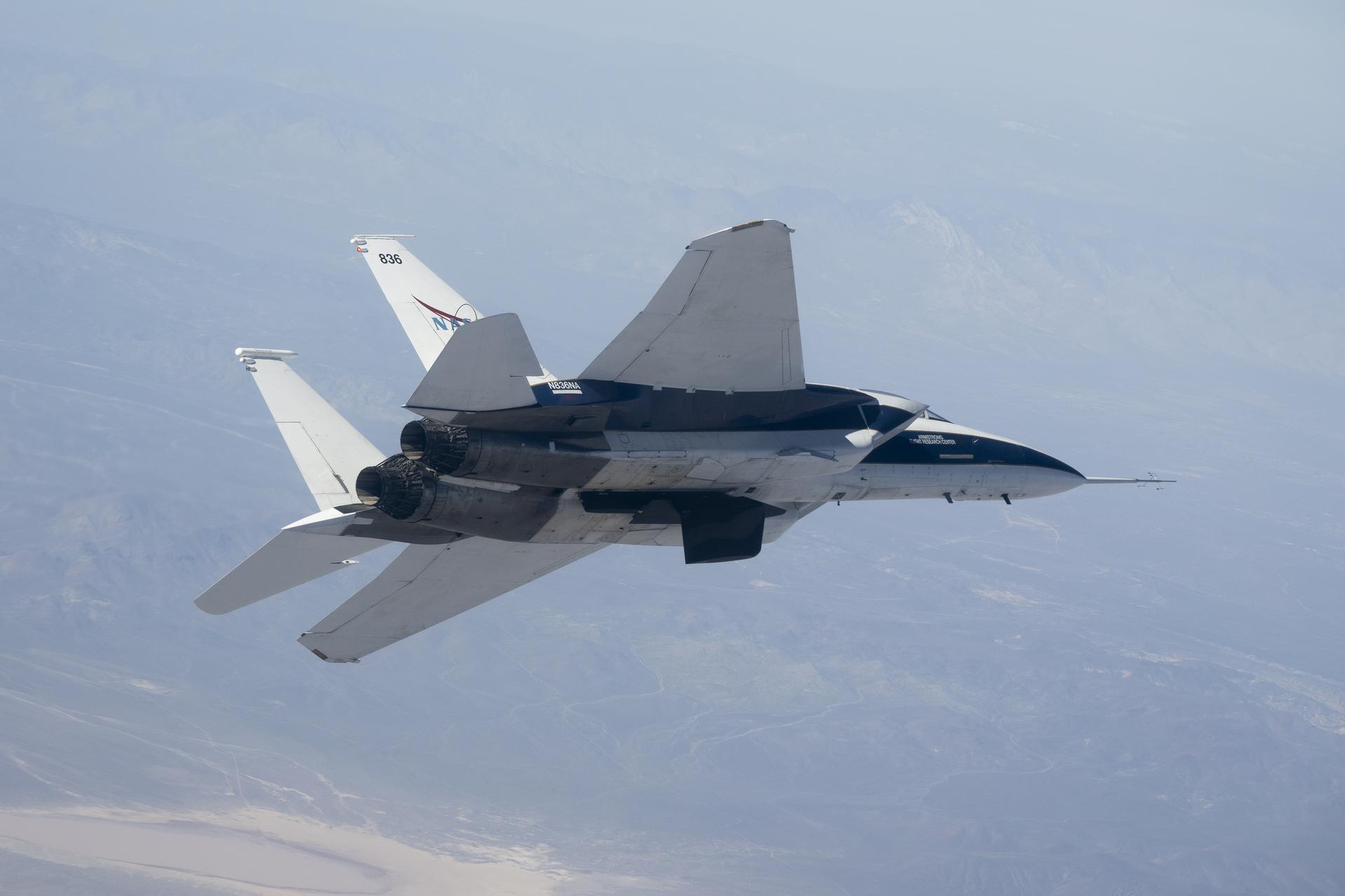
NASA’s Crossflow Attenuated Natural Laminar Flow (CATNLF) scale-model wing flies on a NASA F-15 research jet during a test flight from NASA’s Armstrong Flight Research Center in Edwards, California. The CATNLF technology is designed to maintain smooth airflow, known as laminar flow. NASA will continue flight tests to collect data that validates the CATNLF design and its potential to improve laminar flow, reducing drag and lowering fuel costs for future commercial aircraft.
NASA’s Crossflow Attenuated Natural Laminar Flow (CATNLF) scale-model wing flies for the first time on a NASA F-15 research jet during a test flight from NASA’s Armstrong Flight Research Center in Edwards, California. The 75-minute flight confirmed the aircraft could maneuver safely with the approximately 3-foot-tall test article mounted beneath it. NASA will continue flight tests to collect data that validates the CATNLF design and its potential to improve laminar flow, reducing drag and lowering fuel costs for future commercial aircraft.
NASA’s Crossflow Attenuated Natural Laminar Flow (CATNLF) scale-model wing flies for the first time on a NASA F-15 research jet during a test flight from NASA’s Armstrong Flight Research Center in Edwards, California. The 75-minute flight confirmed the aircraft could maneuver safely with the approximately 3-foot-tall test article mounted beneath it. NASA will continue flight tests to collect data that validates the CATNLF design and its potential to improve laminar flow, reducing drag and lowering fuel costs for future commercial aircraft.
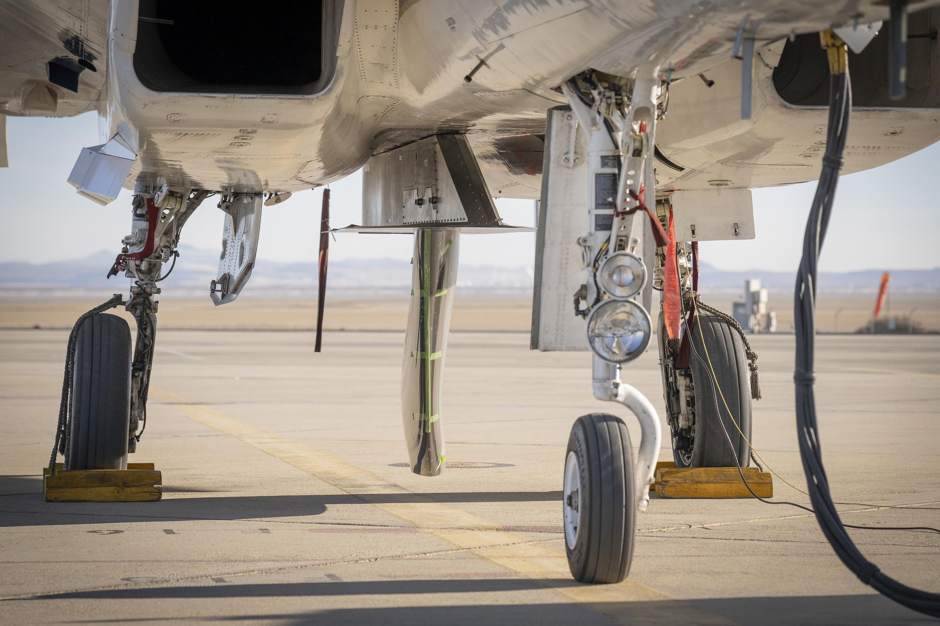
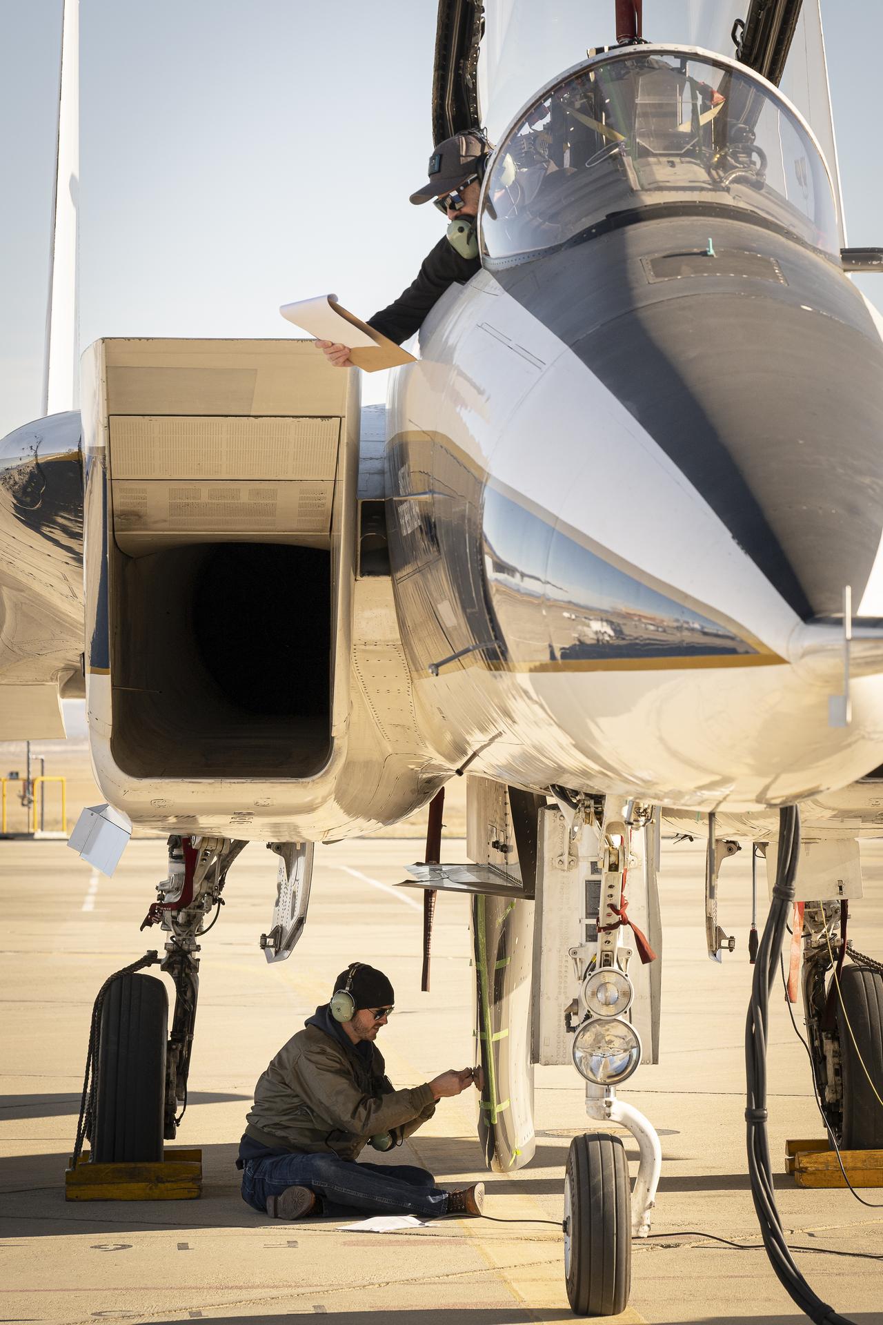
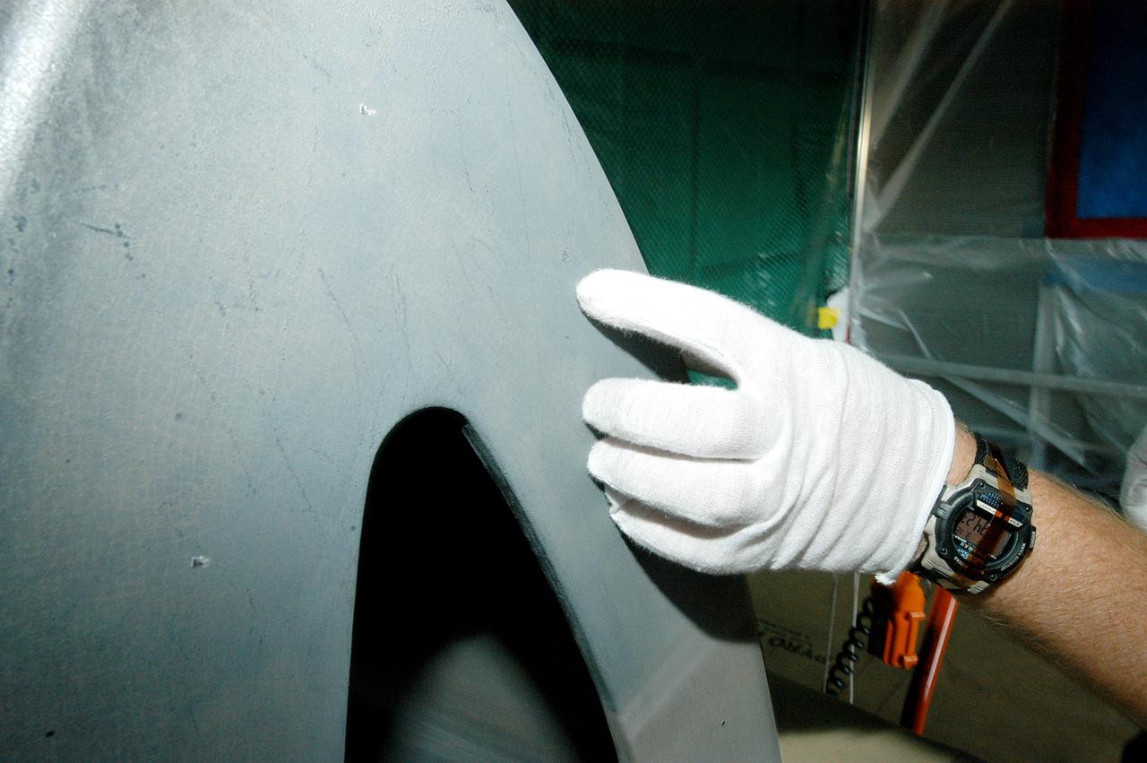
NASA’s Cross Flow Attenuated Natural Laminar Flow test article is mounted beneath the agency’s F-15 research aircraft ahead of the design’s high-speed taxi test on Tuesday, Jan. 12, 2026, at NASA’s Armstrong Flight Research Center in Edwards, California. The 3-foot-tall scale model is designed to increase a phenomenon known as laminar flow and reduce drag, improving efficiency in large, swept wings like those found on most commercial aircraft.
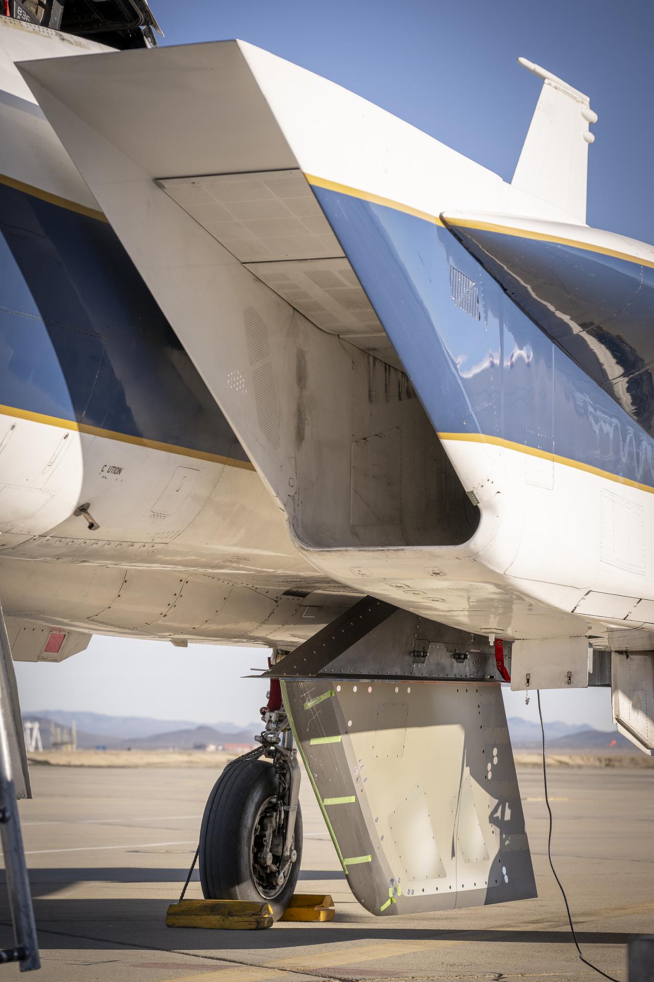
NASA’s Cross Flow Attenuated Natural Laminar Flow test article is mounted beneath the agency’s F-15 research aircraft ahead of the design’s high-speed taxi test on Tuesday, Jan. 12, 2026, at NASA’s Armstrong Flight Research Center in Edwards, California. The 3-foot-tall scale model is designed to increase a phenomenon known as laminar flow and reduce drag, improving efficiency in large, swept wings like those found on most commercial aircraft.
NASA’s Cross Flow Attenuated Natural Laminar Flow test article is mounted beneath the agency’s F-15 research aircraft ahead of the design’s high-speed taxi test on Tuesday, Jan. 12, 2026, at NASA’s Armstrong Flight Research Center in Edwards, California. The 3-foot-tall scale model is designed to increase a phenomenon known as laminar flow and reduce drag, improving efficiency in large, swept wings like those found on most commercial aircraft.
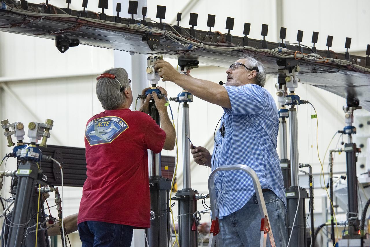
Wally Hargis, left, and Ted Powers complete preparations for testing the Passive Aeroelastic Tailored wing.
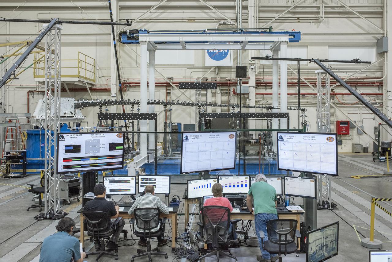
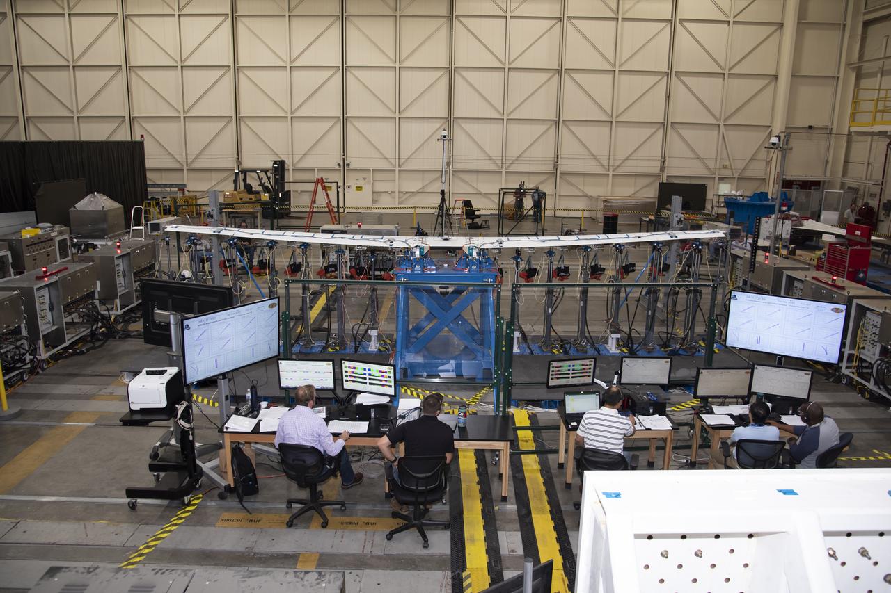
This broad view of the Flight Loads Laboratory at NASA’s Armstrong Flight Research Center in California shows the test set up for the high-aspect ratio Passive Aeroelastic Tailored wing.
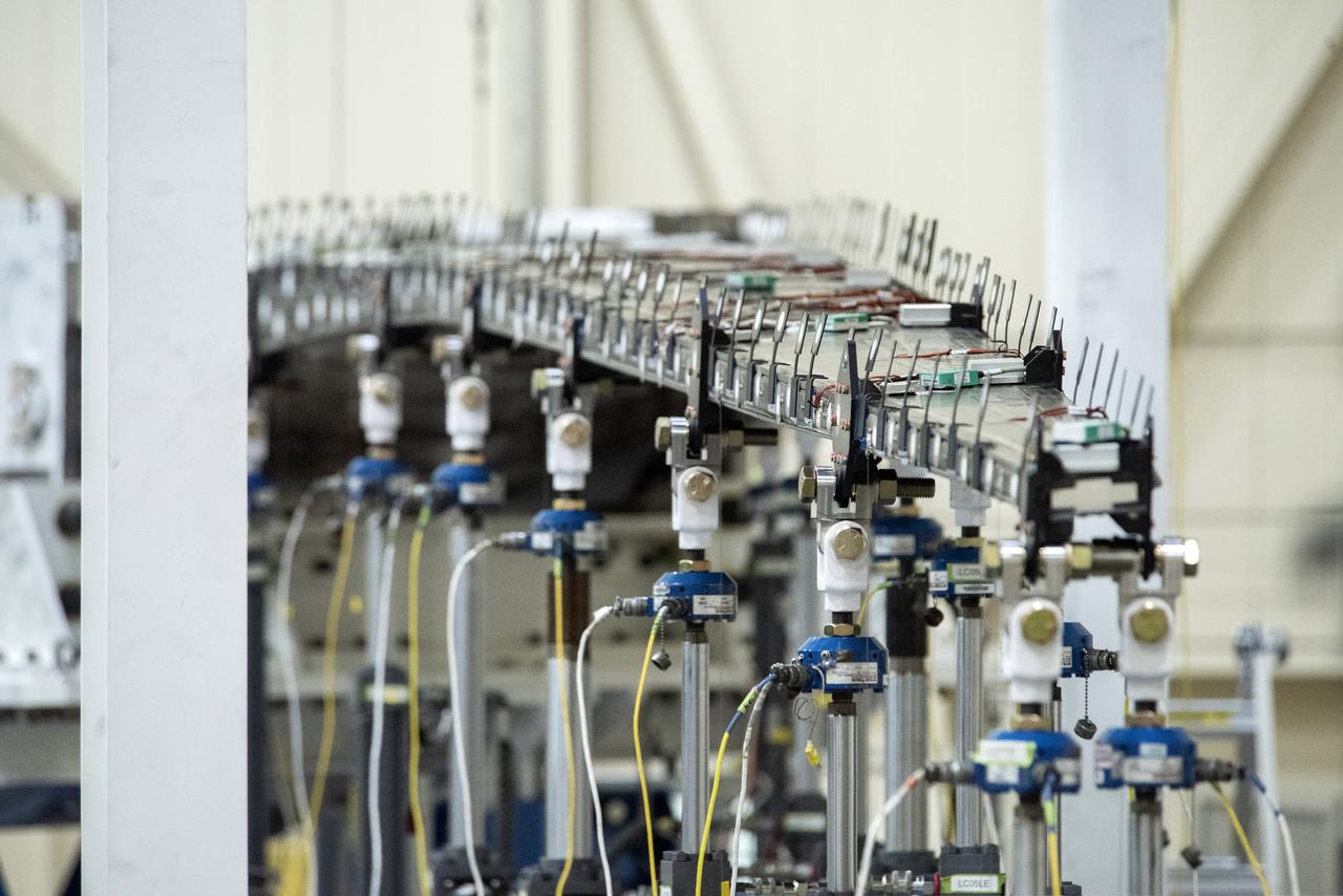
The Passive Aeroelastic Tailored wing is tested in a fixture at the NASA Armstrong Flight Test Center’s Flight Loads Laboratory in California.

Eric Sinks, left, and Ron Haraguchi work through a challenge with the wiring from the Passive Aeroelastic Tailored wing to the test fixture.
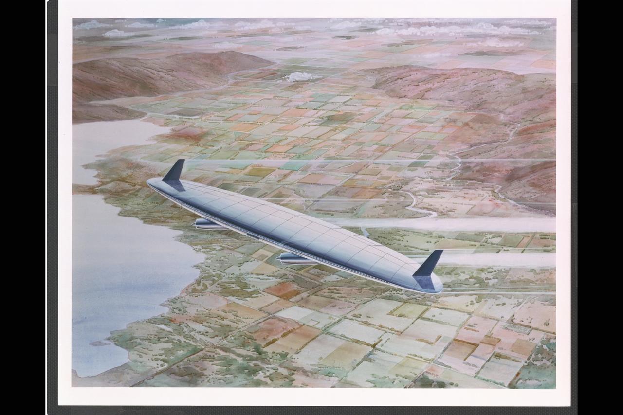
Artist: Rick Guidice Flying Oblique Wing designed by R.T. Jones Artwork
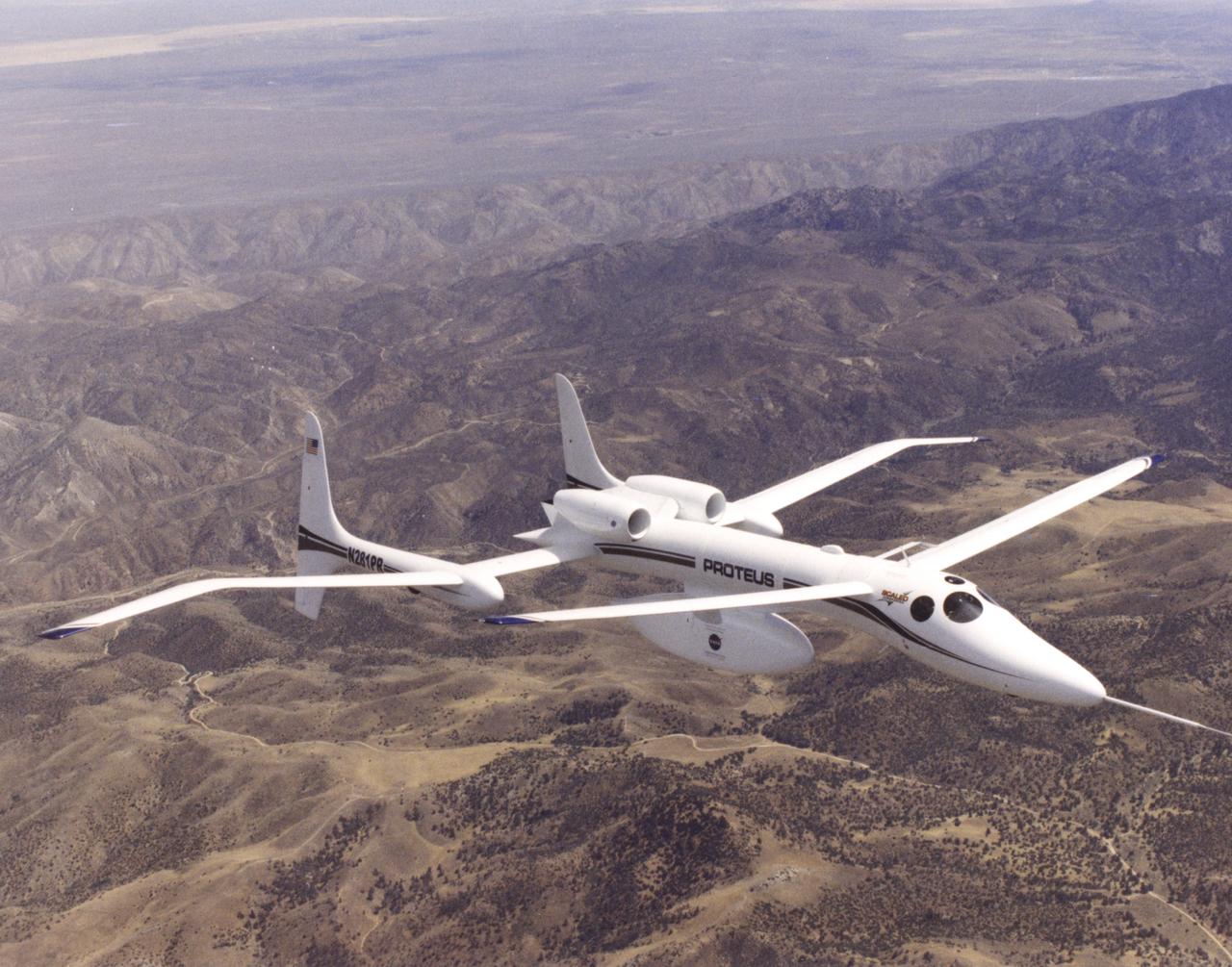
The unusual design of the Proteus high-altitude aircraft, incorporating a gull-wing shape for its main wing and a long, slender forward canard, is clearly visible in this view of the aircraft in flight over the Mojave Desert in California.
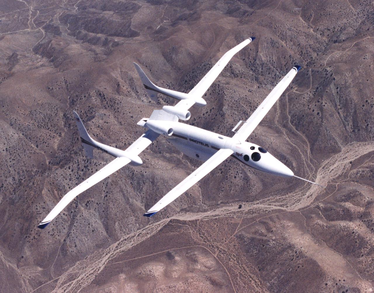
The unusual design of the Proteus high-altitude aircraft, incorporating a gull-wing shape for its main wing and a long, slender forward canard, is clearly visible in this view of the aircraft in flight over the Mojave Desert in California.
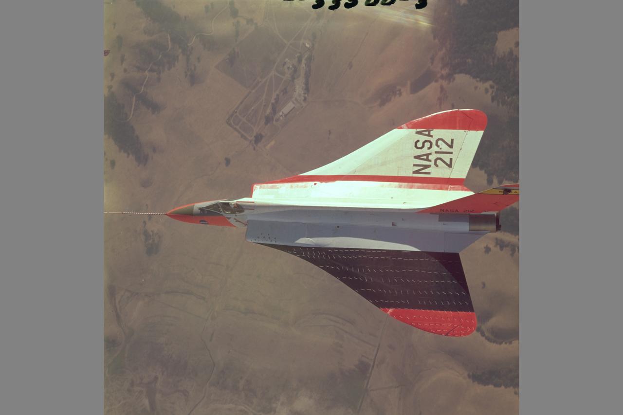
Douglas F5D Skylancer fighter modified with ogee wing planform designed for Mach 2 flight. Shown is the effect of vortex flow on wing tuft alignment in low-speed, high angle-of-attack flight.
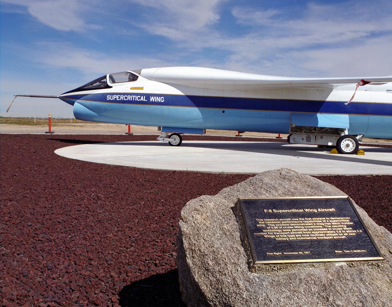
A Vought F-8A Crusader was selected by NASA as the testbed aircraft (designated TF-8A) to install an experimental Supercritical Wing (SCW) in place of the conventional wing. The unique design of the Supercritical Wing reduces the effect of shock waves on the upper surface near Mach 1, which in turn reduces drag. In the photograph the TF-8A Crusader with the Supercritical Wing is shown on static display in front of the NASA Dryden Flight Research Center, Edwards, California. The F-8 SCW aircraft, along with the F-8 Digital Fly-By-Wire aircraft were placed on display on May 27, 1992, at a conference marking the 20th anniversary of the start of the two programs.
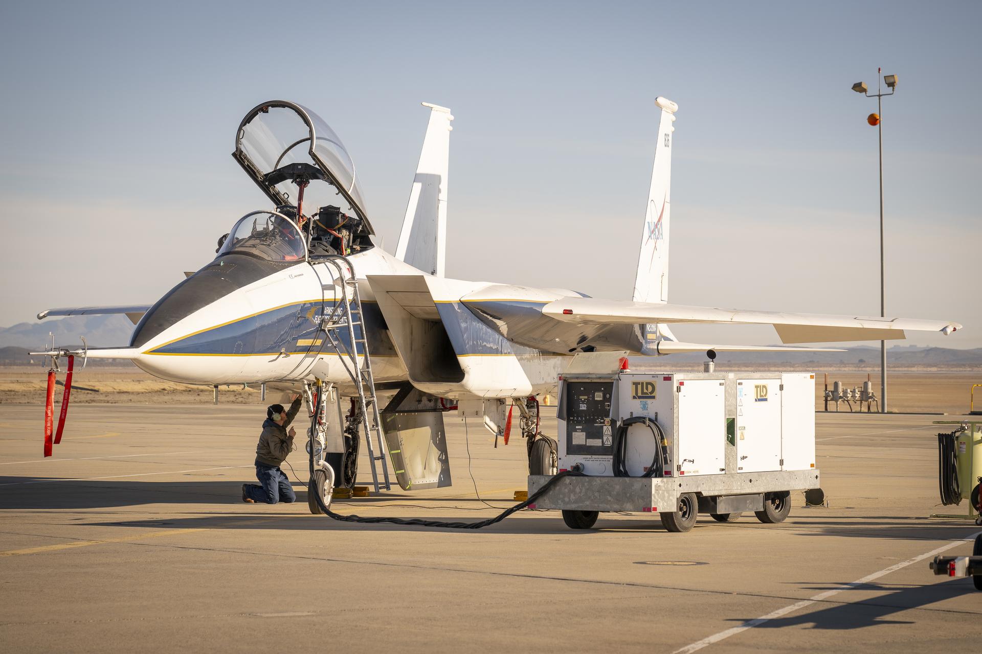
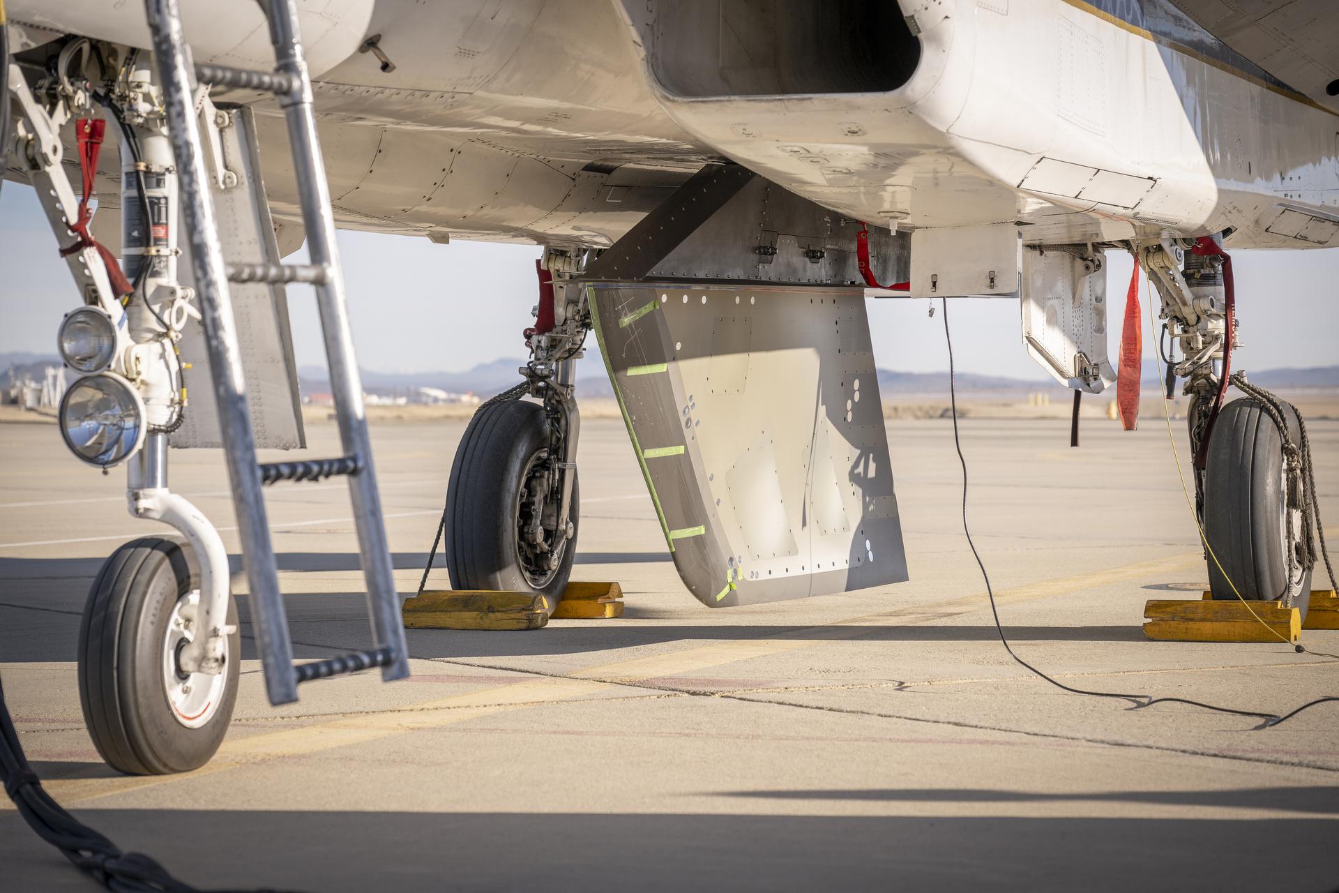
NASA ground crew prepares the agency’s F-15 research aircraft and Cross Flow Attenuated Natural Laminar Flow (CATNLF) test article ahead of its first high-speed taxi test on Tuesday, Jan. 12, 2026, at NASA’s Armstrong Flight Research Center in Edwards, California. The CATNLF design aims to reduce drag on wing surfaces to improve efficiency and, in turn, reduce fuel burn.
NASA ground crew prepares the agency’s F-15 research aircraft and Cross Flow Attenuated Natural Laminar Flow (CATNLF) test article ahead of its first high-speed taxi test on Tuesday, Jan. 12, 2026, at NASA’s Armstrong Flight Research Center in Edwards, California. The CATNLF design aims to reduce drag on wing surfaces to improve efficiency and, in turn, reduce fuel burn.

Oblique Wing model mounted in 11ft W. T. with R. T. Jones, Designer/Engineer. The asymmetrical design allows the plane to fly much faster, yet consume the same fuel and generate less noise.
The X-57 distributed electric aircraft wing that will fly in the final configuration of the flight tests completed its testing at NASA's Armstrong Flight Research Center in California. The test above researched the wing's structure under stress of 120% of the design limit. Tests increased confidence in the wing's durability and calibrated installed strain gauges for inflight load monitoring of the wing. From left to right are Eric Miller, Tony Cash, Welsey Li, Shun-fat Lung and Ashante Jordan.
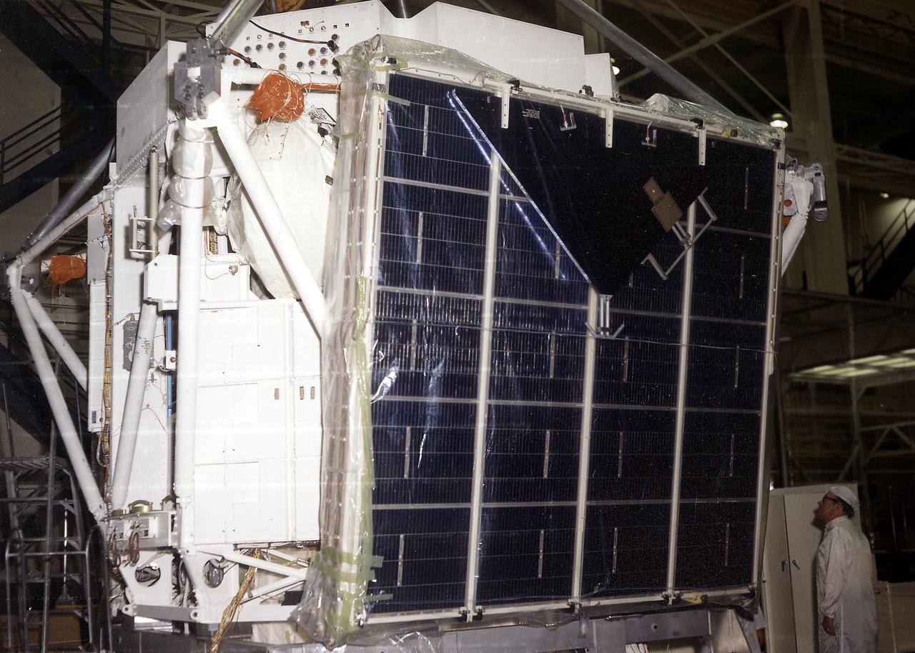
The Apollo Telescope Mount (ATM) was one of four major components of Skylab (1973-1979) that were designed and developed at the Marshall Space Flight Center. In this picture, an ATM solar wing prototype is shown during assembly. A total of four solar wings were required to provide power to the ATM.
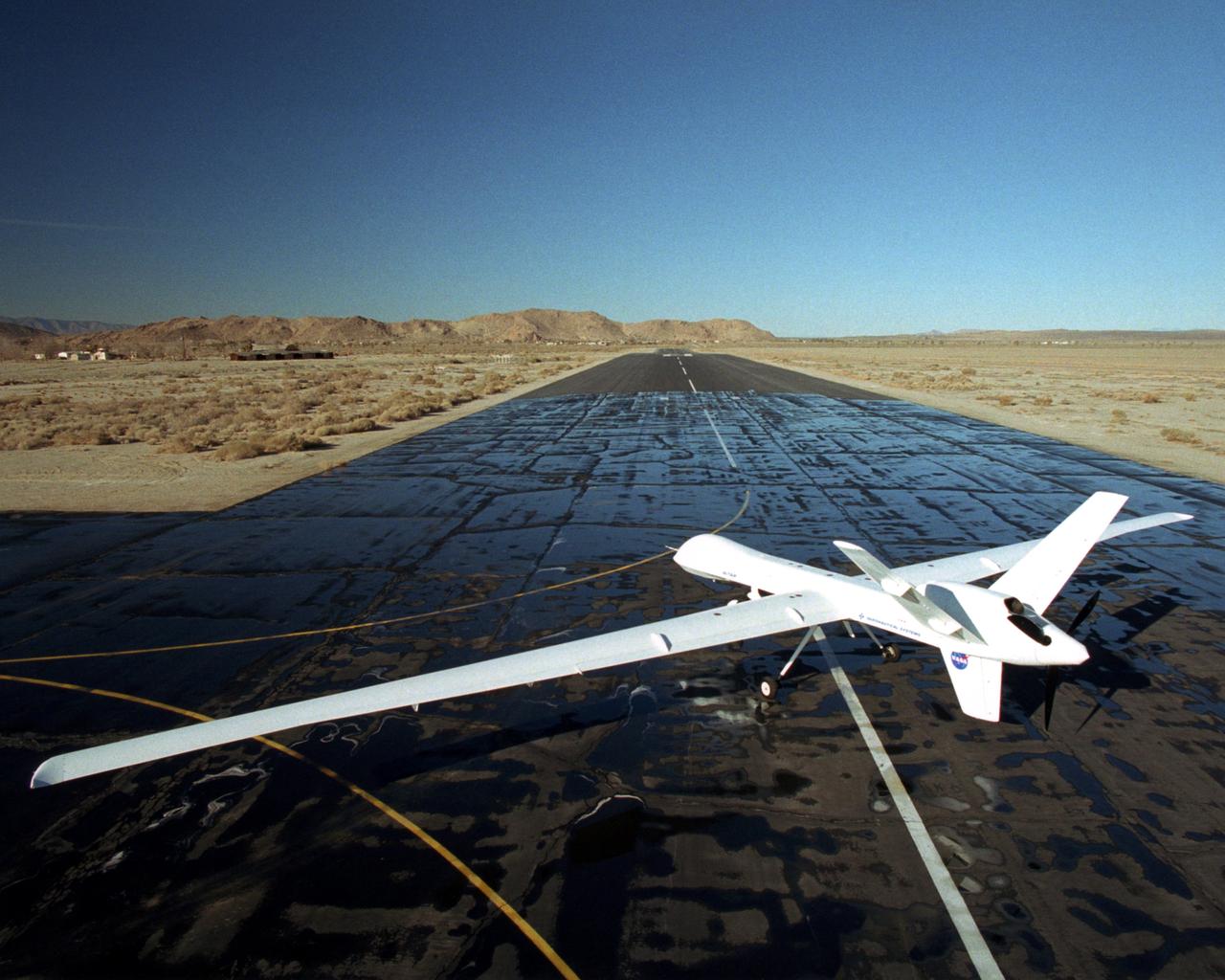
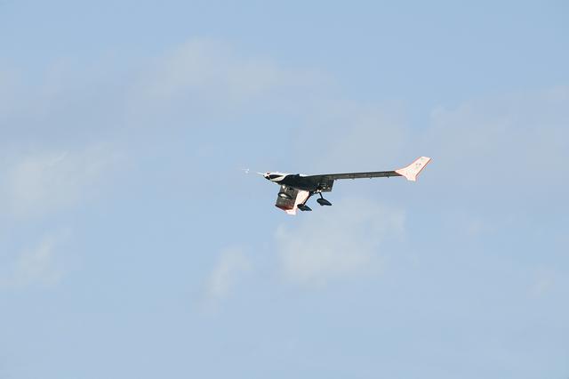
The long, narrow wings of NASA's Altair are designed to allow the unmanned aerial vehicle (UAV) to maintain long-duration flight at high altitudes.
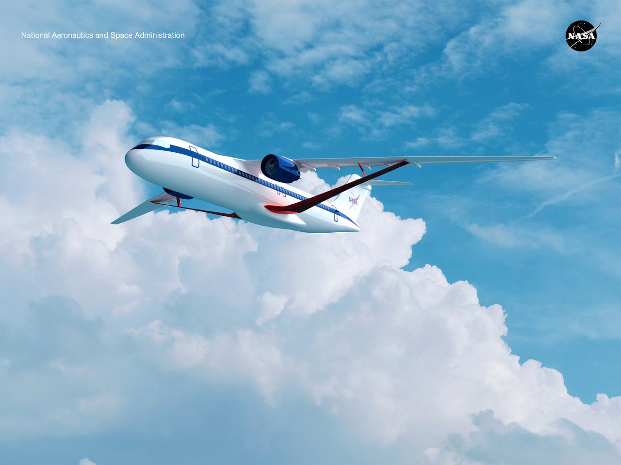
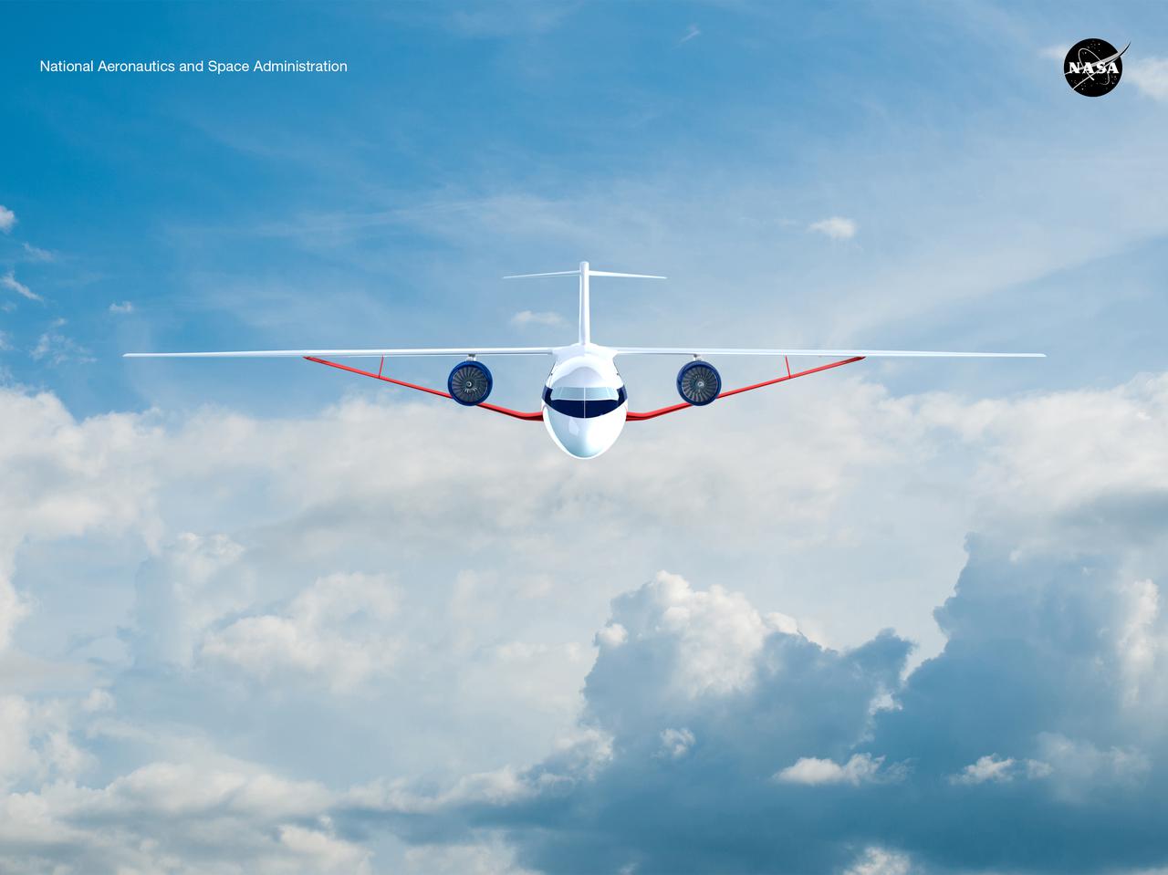
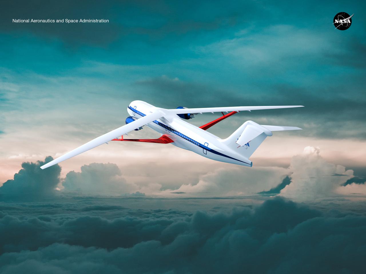
Notice anything different about the wings on this airliner? This conceptual truss-braced wing narrowbody is an aircraft with a 170ft span folding wing. By utilizing trusses, the aircraft can have longer, thinner wings with greater aspect ratios. This, in turn, translates into less drag and 5-10% less fuel burned. The Transonic Truss-Braced Wing aircraft originated from a joint effort by NASA and Boeing to develop subsonic commercial transport concepts – meeting NASA-defined metrics in terms of reduced noise, emissions, and fuel consumption. The design is currently undergoing wind tunnel testing and other studies by NASA researchers.
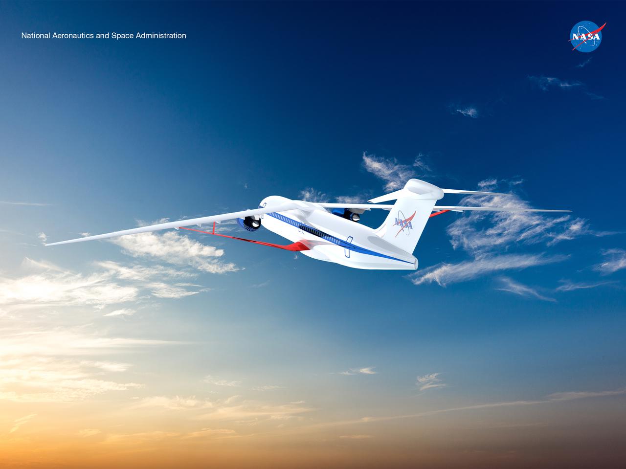
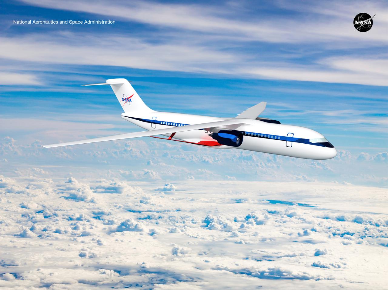
Notice anything different about the wings on this airliner? This conceptual truss-braced wing narrowbody is an aircraft with a 170ft span folding wing. By utilizing trusses, the aircraft can have longer, thinner wings with greater aspect ratios. This, in turn, translates into less drag and 5-10% less fuel burned. The Transonic Truss-Braced Wing aircraft originated from a joint effort by NASA and Boeing to develop subsonic commercial transport concepts – meeting NASA-defined metrics in terms of reduced noise, emissions, and fuel consumption. The design is currently undergoing wind tunnel testing and other studies by NASA researchers.
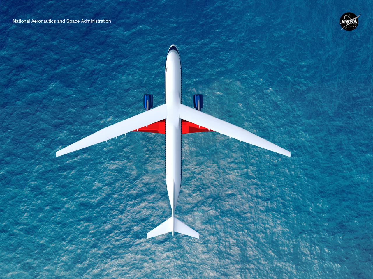
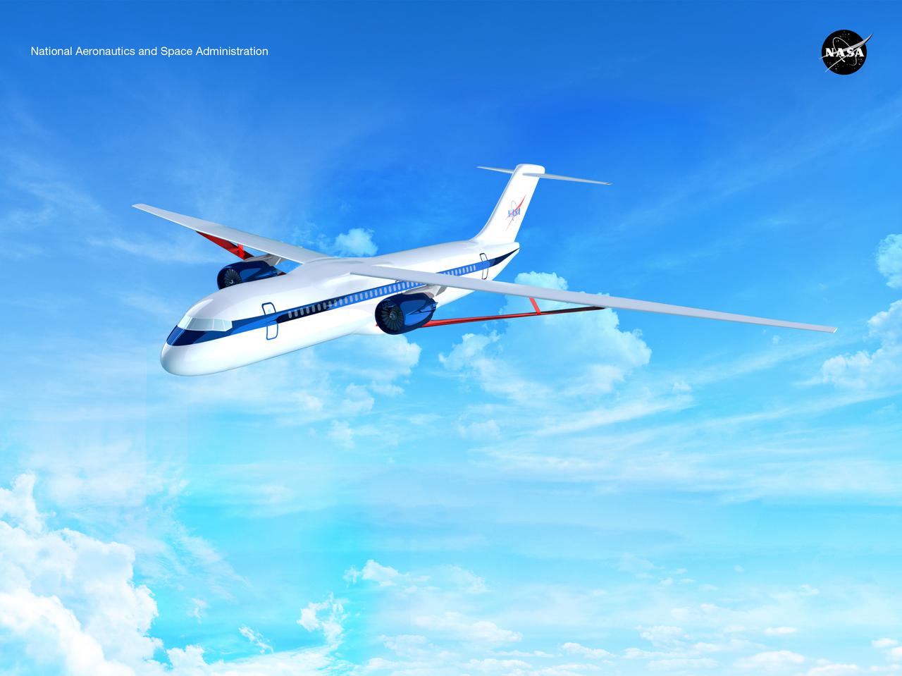
Notice anything different about the wings on this airliner? This conceptual truss-braced wing narrowbody is an aircraft with a 170ft span folding wing. By utilizing trusses, the aircraft can have longer, thinner wings with greater aspect ratios. This, in turn, translates into less drag and 5-10% less fuel burned. The Transonic Truss-Braced Wing aircraft originated from a joint effort by NASA and Boeing to develop subsonic commercial transport concepts – meeting NASA-defined metrics in terms of reduced noise, emissions, and fuel consumption. The design is currently undergoing wind tunnel testing and other studies by NASA researchers.
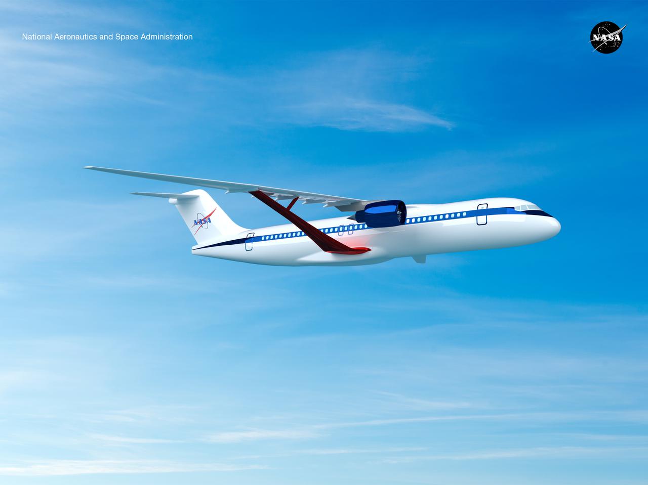
Notice anything different about the wings on this airliner? This conceptual truss-braced wing narrowbody is an aircraft with a 170ft span folding wing. By utilizing trusses, the aircraft can have longer, thinner wings with greater aspect ratios. This, in turn, translates into less drag and 5-10% less fuel burned. The Transonic Truss-Braced Wing aircraft originated from a joint effort by NASA and Boeing to develop subsonic commercial transport concepts – meeting NASA-defined metrics in terms of reduced noise, emissions, and fuel consumption. The design is currently undergoing wind tunnel testing and other studies by NASA researchers.
Notice anything different about the wings on this airliner? This conceptual truss-braced wing narrowbody is an aircraft with a 170ft span folding wing. By utilizing trusses, the aircraft can have longer, thinner wings with greater aspect ratios. This, in turn, translates into less drag and 5-10% less fuel burned. The Transonic Truss-Braced Wing aircraft originated from a joint effort by NASA and Boeing to develop subsonic commercial transport concepts – meeting NASA-defined metrics in terms of reduced noise, emissions, and fuel consumption. The design is currently undergoing wind tunnel testing and other studies by NASA researchers.
Notice anything different about the wings on this airliner? This conceptual truss-braced wing narrowbody is an aircraft with a 170ft span folding wing. By utilizing trusses, the aircraft can have longer, thinner wings with greater aspect ratios. This, in turn, translates into less drag and 5-10% less fuel burned. The Transonic Truss-Braced Wing aircraft originated from a joint effort by NASA and Boeing to develop subsonic commercial transport concepts – meeting NASA-defined metrics in terms of reduced noise, emissions, and fuel consumption. The design is currently undergoing wind tunnel testing and other studies by NASA researchers.
Notice anything different about the wings on this airliner? This conceptual truss-braced wing narrowbody is an aircraft with a 170ft span folding wing. By utilizing trusses, the aircraft can have longer, thinner wings with greater aspect ratios. This, in turn, translates into less drag and 5-10% less fuel burned. The Transonic Truss-Braced Wing aircraft originated from a joint effort by NASA and Boeing to develop subsonic commercial transport concepts – meeting NASA-defined metrics in terms of reduced noise, emissions, and fuel consumption. The design is currently undergoing wind tunnel testing and other studies by NASA researchers.
Notice anything different about the wings on this airliner? This conceptual truss-braced wing narrowbody is an aircraft with a 170ft span folding wing. By utilizing trusses, the aircraft can have longer, thinner wings with greater aspect ratios. This, in turn, translates into less drag and 5-10% less fuel burned. The Transonic Truss-Braced Wing aircraft originated from a joint effort by NASA and Boeing to develop subsonic commercial transport concepts – meeting NASA-defined metrics in terms of reduced noise, emissions, and fuel consumption. The design is currently undergoing wind tunnel testing and other studies by NASA researchers.
Notice anything different about the wings on this airliner? This conceptual truss-braced wing narrowbody is an aircraft with a 170ft span folding wing. By utilizing trusses, the aircraft can have longer, thinner wings with greater aspect ratios. This, in turn, translates into less drag and 5-10% less fuel burned. The Transonic Truss-Braced Wing aircraft originated from a joint effort by NASA and Boeing to develop subsonic commercial transport concepts – meeting NASA-defined metrics in terms of reduced noise, emissions, and fuel consumption. The design is currently undergoing wind tunnel testing and other studies by NASA researchers.
Notice anything different about the wings on this airliner? This conceptual truss-braced wing narrowbody is an aircraft with a 170ft span folding wing. By utilizing trusses, the aircraft can have longer, thinner wings with greater aspect ratios. This, in turn, translates into less drag and 5-10% less fuel burned. The Transonic Truss-Braced Wing aircraft originated from a joint effort by NASA and Boeing to develop subsonic commercial transport concepts – meeting NASA-defined metrics in terms of reduced noise, emissions, and fuel consumption. The design is currently undergoing wind tunnel testing and other studies by NASA researchers.
Notice anything different about the wings on this airliner? This conceptual truss-braced wing narrowbody is an aircraft with a 170ft span folding wing. By utilizing trusses, the aircraft can have longer, thinner wings with greater aspect ratios. This, in turn, translates into less drag and 5-10% less fuel burned. The Transonic Truss-Braced Wing aircraft originated from a joint effort by NASA and Boeing to develop subsonic commercial transport concepts – meeting NASA-defined metrics in terms of reduced noise, emissions, and fuel consumption. The design is currently undergoing wind tunnel testing and other studies by NASA researchers.
Notice anything different about the wings on this airliner? This conceptual truss-braced wing narrowbody is an aircraft with a 170ft span folding wing. By utilizing trusses, the aircraft can have longer, thinner wings with greater aspect ratios. This, in turn, translates into less drag and 5-10% less fuel burned. The Transonic Truss-Braced Wing aircraft originated from a joint effort by NASA and Boeing to develop subsonic commercial transport concepts – meeting NASA-defined metrics in terms of reduced noise, emissions, and fuel consumption. The design is currently undergoing wind tunnel testing and other studies by NASA researchers.
Notice anything different about the wings on this airliner? This conceptual truss-braced wing narrowbody is an aircraft with a 170ft span folding wing. By utilizing trusses, the aircraft can have longer, thinner wings with greater aspect ratios. This, in turn, translates into less drag and 5-10% less fuel burned. The Transonic Truss-Braced Wing aircraft originated from a joint effort by NASA and Boeing to develop subsonic commercial transport concepts – meeting NASA-defined metrics in terms of reduced noise, emissions, and fuel consumption. The design is currently undergoing wind tunnel testing and other studies by NASA researchers.
Notice anything different about the wings on this airliner? This conceptual truss-braced wing narrowbody is an aircraft with a 170ft span folding wing. By utilizing trusses, the aircraft can have longer, thinner wings with greater aspect ratios. This, in turn, translates into less drag and 5-10% less fuel burned. The Transonic Truss-Braced Wing aircraft originated from a joint effort by NASA and Boeing to develop subsonic commercial transport concepts – meeting NASA-defined metrics in terms of reduced noise, emissions, and fuel consumption. The design is currently undergoing wind tunnel testing and other studies by NASA researchers.
Notice anything different about the wings on this airliner? This conceptual truss-braced wing narrowbody is an aircraft with a 170ft span folding wing. By utilizing trusses, the aircraft can have longer, thinner wings with greater aspect ratios. This, in turn, translates into less drag and 5-10% less fuel burned. The Transonic Truss-Braced Wing aircraft originated from a joint effort by NASA and Boeing to develop subsonic commercial transport concepts – meeting NASA-defined metrics in terms of reduced noise, emissions, and fuel consumption. The design is currently undergoing wind tunnel testing and other studies by NASA researchers.
Notice anything different about the wings on this airliner? This conceptual truss-braced wing narrowbody is an aircraft with a 170ft span folding wing. By utilizing trusses, the aircraft can have longer, thinner wings with greater aspect ratios. This, in turn, translates into less drag and 5-10% less fuel burned. The Transonic Truss-Braced Wing aircraft originated from a joint effort by NASA and Boeing to develop subsonic commercial transport concepts – meeting NASA-defined metrics in terms of reduced noise, emissions, and fuel consumption. The design is currently undergoing wind tunnel testing and other studies by NASA researchers.
In this 1950 view of the left side of the NACA High-Speed Flight Research Station's X-4 research aircraft, the low swept wing and horizontal taillest design are seen. The X-4 Bantam, a single-place, low swept-wing, semi-tailless aircraft, was designed and built by Northrop Aircraft, Inc. It had no horizontal tail surfaces and its mission was to obtain in-flight data on the stability and control of semi-tailless aircraft at high subsonic speeds.
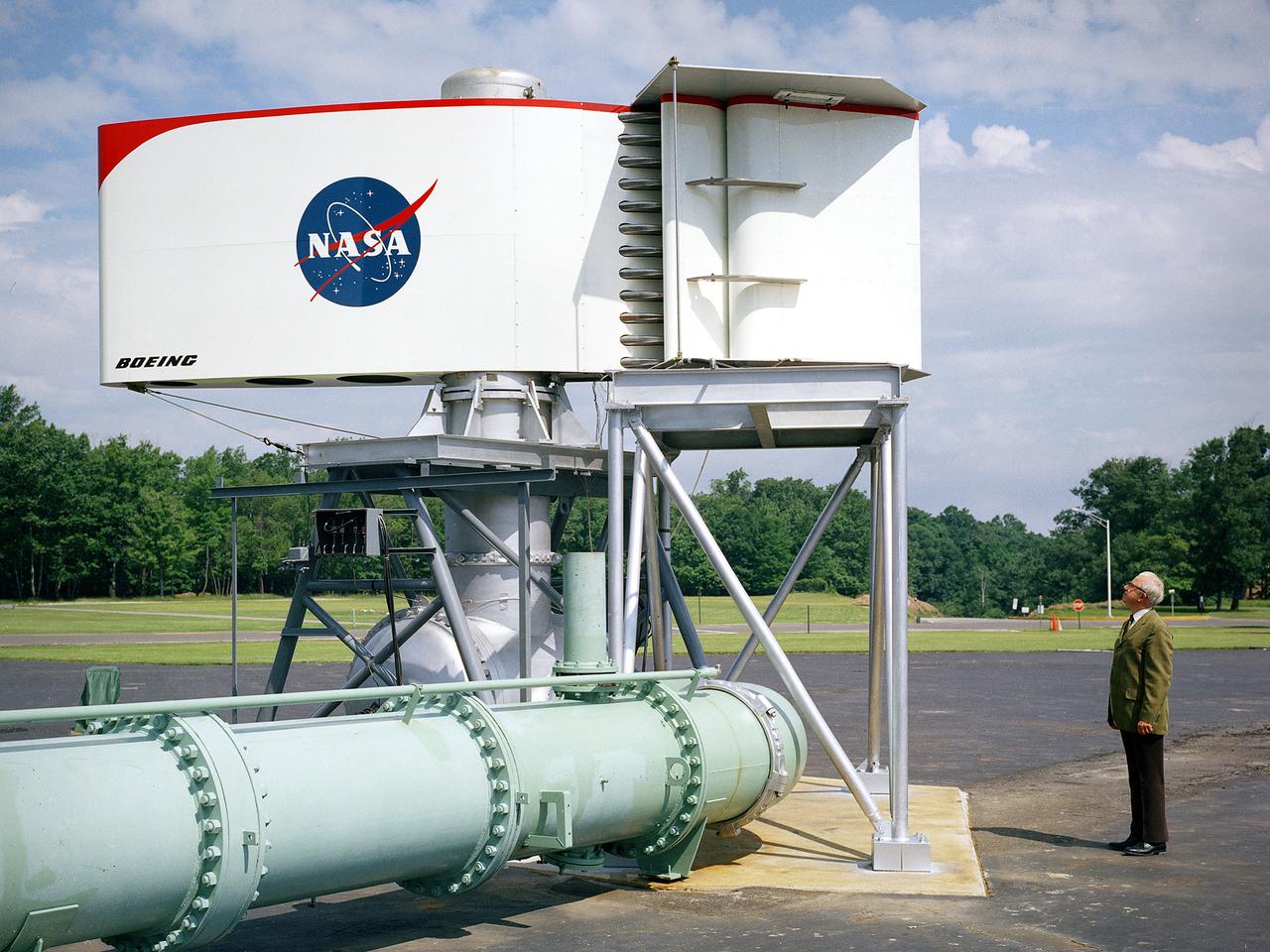
The augmentor wing concept was introduced during the early 1960s to enhance the performance of vertical and short takeoff (VSTOL) aircraft. The leading edge of the wing has full-span vertical flaps, and the trailing edge has double-slotted flaps. This provides aircraft with more control in takeoff and landing conditions. The augmentor wing also produced lower noise levels than other VSTOL designs. In the early 1970s Boeing Corporation built a Buffalo C-8A augmentor wing research aircraft for Ames Research Center. Researches at Lewis Research Center concentrated their efforts on reducing the noise levels of the wing. They initially used small-scale models to develop optimal nozzle screening methods. They then examined the nozzle designs on a large-scale model, seen here on an external test stand. This test stand included an airflow system, nozzle, the augmentor wing, and a muffler system below to reduce the atmospheric noise levels. The augmentor was lined with noise-reducing acoustic panels. The Lewis researchers were able to adjust the airflow to simulate conditions at takeoff and landing. Once the conditions were stabilized they took noise measurements from microphones placed in all directions from the wing, including an aircraft flying over. They found that the results coincided with the earlier small-scale studies for landing situations but not takeoffs. The acoustic panels were found to be successful.
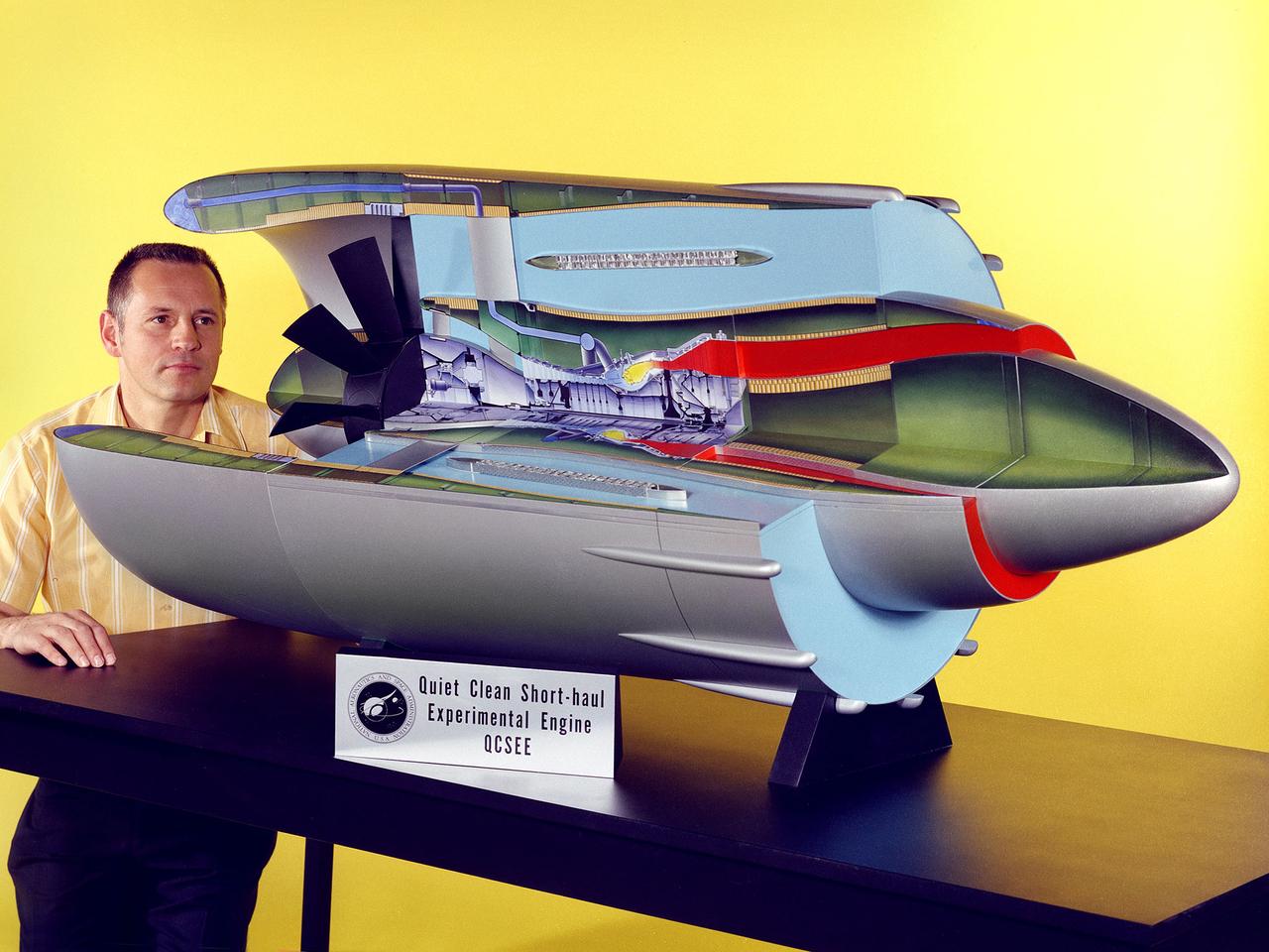
Program manager Carl Ciepluch poses with a model of the Quiet Clean Short Haul Experimental Engine (QCSEE) conceived by the National Aeronautics and Space Administration (NASA) Lewis Research Center. The QCSEE engine was designed to power future short-distance transport aircraft without generating significant levels of noise or pollution and without hindering performance. The engines were designed to be utilized on aircraft operating from small airports with short runways. Lewis researchers investigated two powered-lift designs and an array of new technologies to deal with the shorter runways. Lewis contracted General Electric to design the two QCSEE engines—one with over-the-wing power-lift and one with an under-the-wing design. A scale model of the over-the-wing engine was tested in the Full Scale Tunnel at the Langley Research Center in 1975 and 1976. Lewis researchers investigated both versions in a specially-designed test stand, the Engine Noise Test Facility, on the hangar apron. The QCSEE engines met the goals set out by the NASA researchers. The aircraft industry, however, never built the short-distance transport aircraft for which the engines were intended. Different technological elements of the engine, however, were applied to some future General Electric engines.
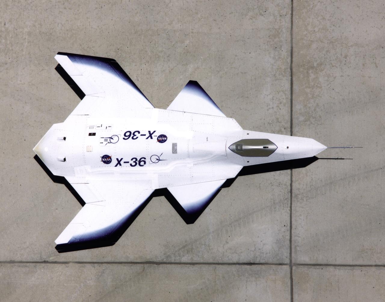
This look-down view of the X-36 Tailless Fighter Agility Research Aircraft on the ramp at NASA’s Dryden Flight Research Center, Edwards, California, clearly shows the unusual wing and canard design of the remotely-piloted aircraft.
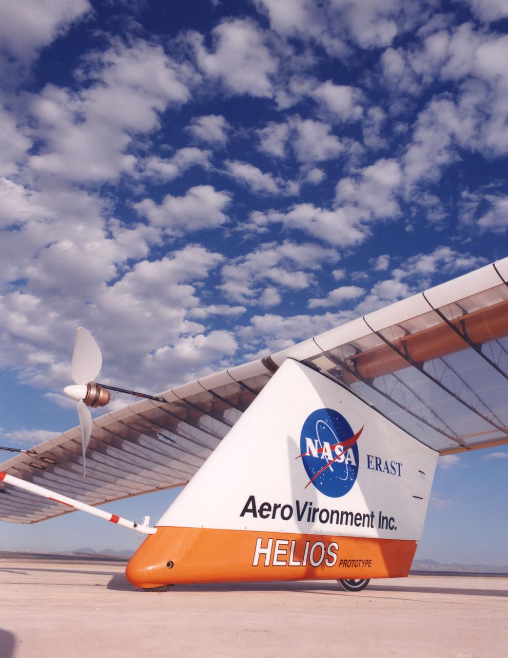
Closeup of the Helios Prototype, the latest and largest example of a slow-flying ultralight flying wing designed for high-altitude, long-duration Earth science or telecommunications relay missions.
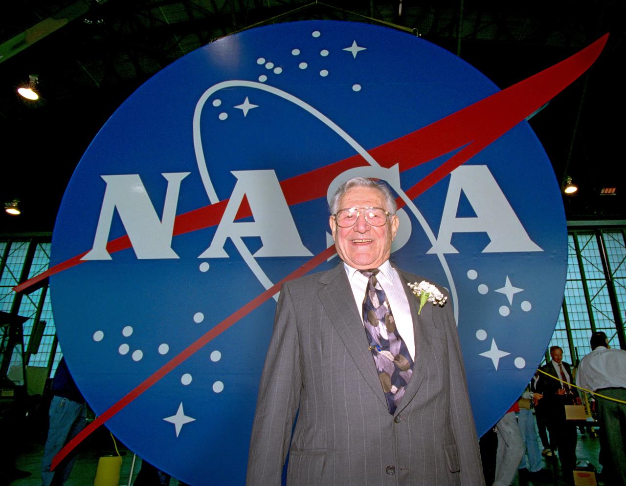
In 1949, after graduating from the Cleveland Institute of Art, James “Jim” Modarelli began his career as an artist-designer at the laboratory that would become the NASA Glenn Research Center. When the NACA was approved to be absorbed into the new space agency—NASA, employees were invited to submit designs for the Agency’s logo. Modarelli, who was serving as the Management Services Division Chief at the time, submitted the winning designs. The official NASA seal and the less formal NASA “meatball” insignia (shown here) are among the most recognized emblems in the world. The logos, which include symbols representing the space and aeronautics missions of NASA, became official in 1959. In July 1958, Modarelli participated in a tour at the Ames Unitary Plan Wind Tunnel, where he viewed a model of a radical supersonic airplane designed for flight at Mach 3.0. With a cambered, twisted arrow wing and an upturned nose, the model deeply impressed Modarelli. He later stylized the radical features of the arrow-wing configuration in his evolution of the NASA seal design; the wing would also become an element of the NASA insignia.
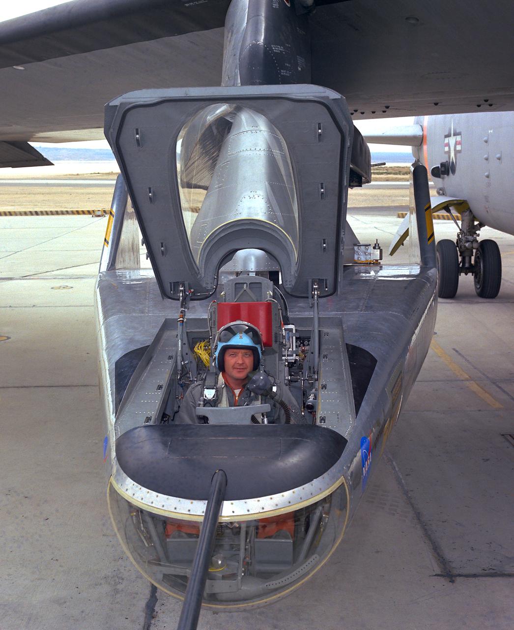
NASA research pilot Milt Thompson sits in the M2-F2 "heavyweight" lifting body research vehicle before a 1966 test flight. The M2-F2 and the other lifting-body designs were all attached to a wing pylon on NASA’s B-52 mothership and carried aloft. The vehicles were then drop-launched and, at the end of their flights, glided back to wheeled landings on the dry lake or runway at Edwards AFB. The lifting body designs influenced the design of the Space Shuttle and were also reincarnated in the design of the X-38 in the 1990s.
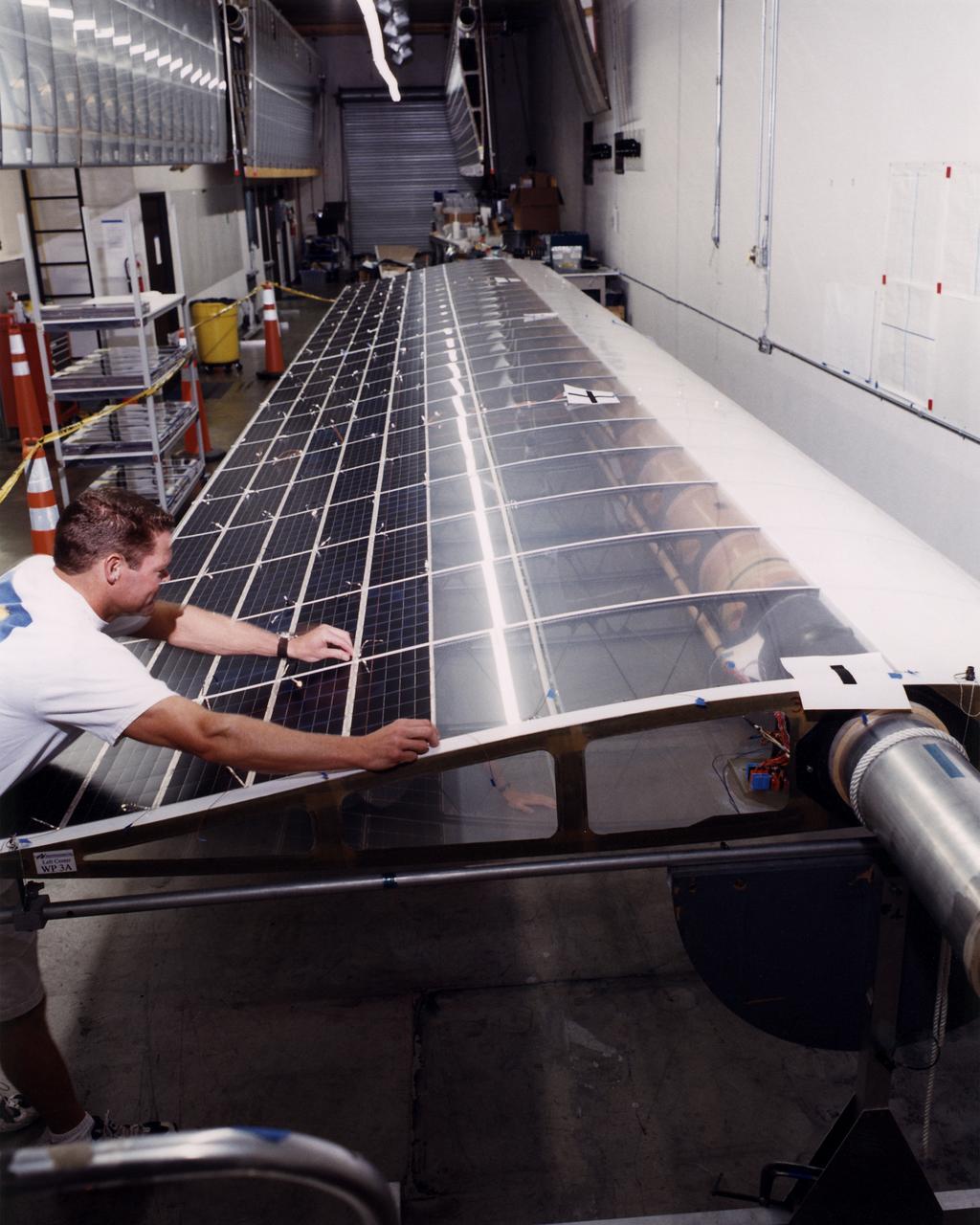
Technician Marshall MacCready carefully lays a panel of solar cells into place on a wing section of the Helios Prototype flying wing at AeroVironment's Design Development Center in Simi Valley, California. The bi-facial cells, manufactured by SunPower, Inc., of Sunnyvale, California, are among 64,000 solar cells which have been installed on the solar-powered aircraft to provide electricity to its 14 motors and operating systems.
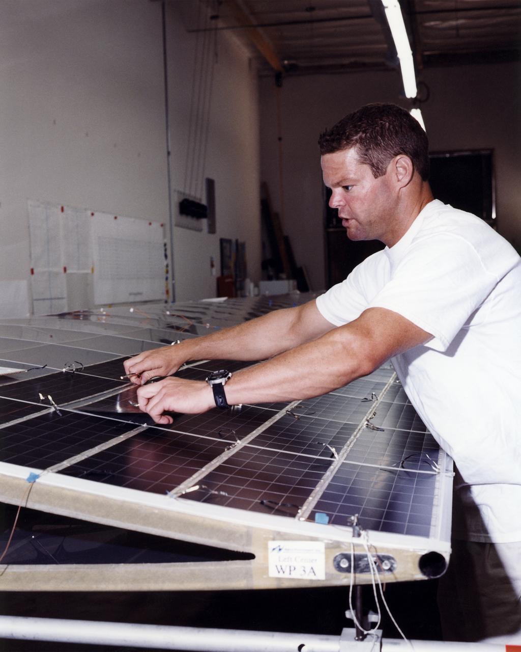
Technician Marshall MacCready carefully lays a panel of solar cells into place on a wing section of the Helios Prototype flying wing at AeroVironment's Design Development Center in Simi Valley, California. More than 1,800 panels containing some 64,000 bi-facial cells, fabricated by SunPower, Inc., of Sunnyvale, California, have been installed on the solar-powered aircraft to provide electricity to its 14 motors and operating systems.
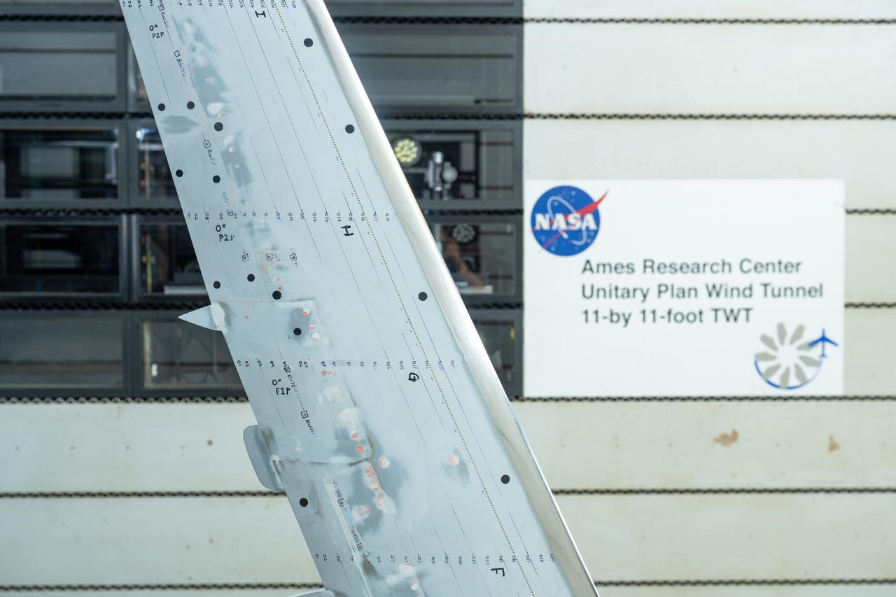
NASA’s Sustainable Flight Demonstrator project concluded wind tunnel testing in the fall of 2024. Tests on a Boeing-built X-66 model were completed at NASA’s Ames Research Center in Silicon Valley, California, in the 11-Foot Transonic Unitary Plan Facility. Pressure points, which are drilled holes with data sensors attached, are installed along the edge of the wing and allow engineers to understand the characteristics of airflow and will influence the final design of the wing.
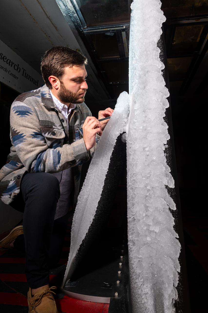
Thomas Ozoroski, an Icing Researcher, is shown documenting ice accretion on the leading edge of the next-generation Transonic Truss-Braced Wing design at NASA Glenn's Icing Research Center. This critical research will help understand icing effects for future, high-lift, ultra-efficient aircraft. Photo Credit: (NASA/Jordan Salkin)
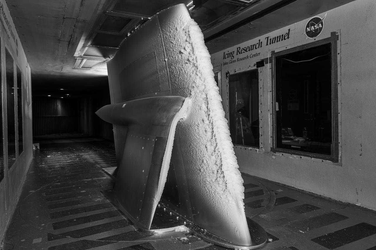
Ice accretion is shown on the leading edge of the next-generation Transonic Truss-Braced Wing design at NASA Glenn's Icing Research Center. This critical research will help understand icing effects for future, high-lift, ultra-efficient aircraft. Photo Credit: (NASA/Jordan Salkin)
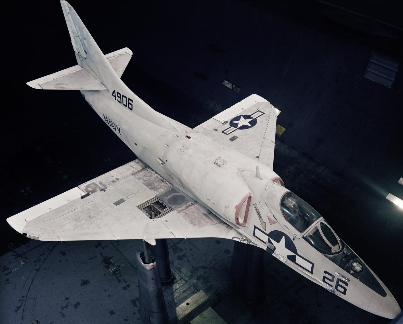
Battle Damage test conducted in the Ames 40x80ft. Subsonic Wind Tunnel, Ames Research Center Moffett Field, CA on the Navy A-4B airplane (The delta winged, single-engined Skyhawk was designed and produced by Douglas Aircraft Company model I.d. Numbers 4906 and 3A244)
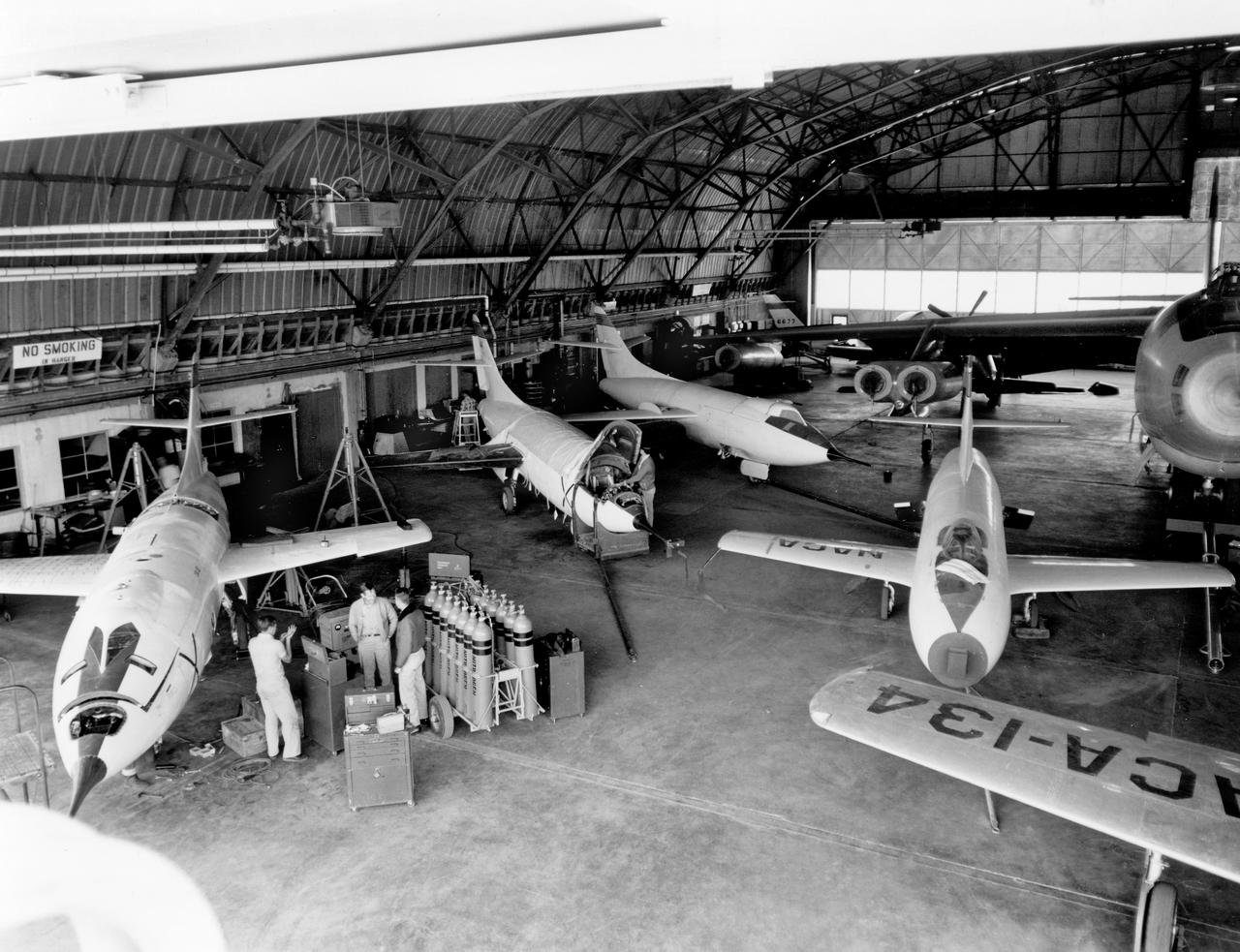
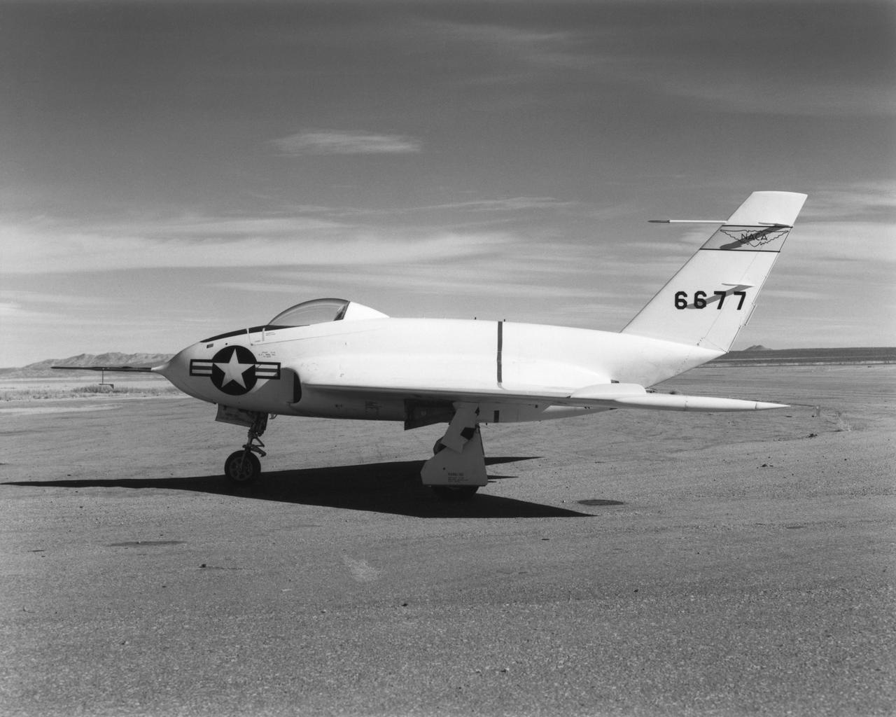
The aircraft in this 1953 photo of the National Advisory Committee for Aeronautics (NACA) hangar at South Base of Edwards Air Force Base showed the wide range of research activities being undertaken. On the left side of the hangar are the three D-558-2 research aircraft. These were designed to test swept wings at supersonic speeds approaching Mach 2. The front D-558-2 is the third built (NACA 145/Navy 37975). It has been modified with a leading-edge chord extension. This was one of a number of wing modifications, using different configurations of slats and/or wing fences, to ease the airplane's tendency to pitch-up. NACA 145 had both a jet and a rocket engine. The middle aircraft is NACA 144 (Navy 37974), the second built. It was all-rocket powered, and Scott Crossfield made the first Mach 2 flight in this aircraft on November 20, 1953. The aircraft in the back is D-558-2 number 1. NACA 143 (Navy 37973) was also carried both a jet and a rocket engine in 1953. It had been used for the Douglas contractor flights, then was turned over to the NACA. The aircraft was not converted to all-rocket power until June 1954. It made only a single NACA flight before NACA's D-558-2 program ended in 1956. Beside the three D-558-2s is the third D-558-1. Unlike the supersonic D-558-2s, it was designed for flight research at transonic speeds, up to Mach 1. The D-558-1 was jet-powered, and took off from the ground. The D-558-1's handling was poor as it approached Mach 1. Given the designation NACA 142 (Navy 37972), it made a total of 78 research flights, with the last in June 1953. In the back of the hangar is the X-4 (Air Force 46-677). This was a Northrop-built research aircraft which tested a swept wing design without horizontal stabilizers. The aircraft proved unstable in flight at speeds above Mach 0.88. The aircraft showed combined pitching, rolling, and yawing motions, and the design was considered unsuitable. The aircraft, the second X-4 built, was then used as a pilot traine
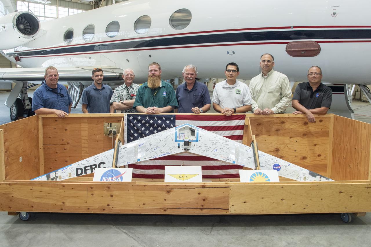
Preliminary Research Aerodynamic Design to Lower Drag, or Prandtl-D1, will be displayed in an upcoming Innovations Gallery at the National Air and Space Museum, the Smithsonian Institute. The aircraft, which flew from NASA's Armstrong Flight Research Center in California, uses a method of aircraft design that introduces a twist that results in a more efficient wing. From left are Robert "Red" Jensen, Logan Shaw, Christian Gelzer, Justin Hall, Al Bowers, Oscar Murillo, Brian Eslinger and Derek Abramson
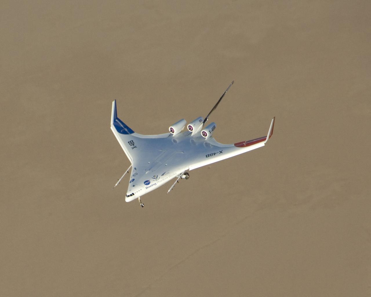
Boeing Phantom Works' subscale Blended Wing Body technology demonstration aircraft began its initial flight tests from NASA's Dryden Flight Research Center at Edwards Air Force Base, Calif. in the summer of 2007. The 8.5 percent dynamically scaled unmanned aircraft, designated the X-48B by the Air Force, is designed to mimic the aerodynamic characteristics of a full-scale large cargo transport aircraft with the same blended wing body shape. The initial flight tests focused on evaluation of the X-48B's low-speed flight characteristics and handling qualities. About 25 flights were planned to gather data in these low-speed flight regimes. Based on the results of the initial flight test series, a second set of flight tests was planned to test the aircraft's low-noise and handling characteristics at transonic speeds.
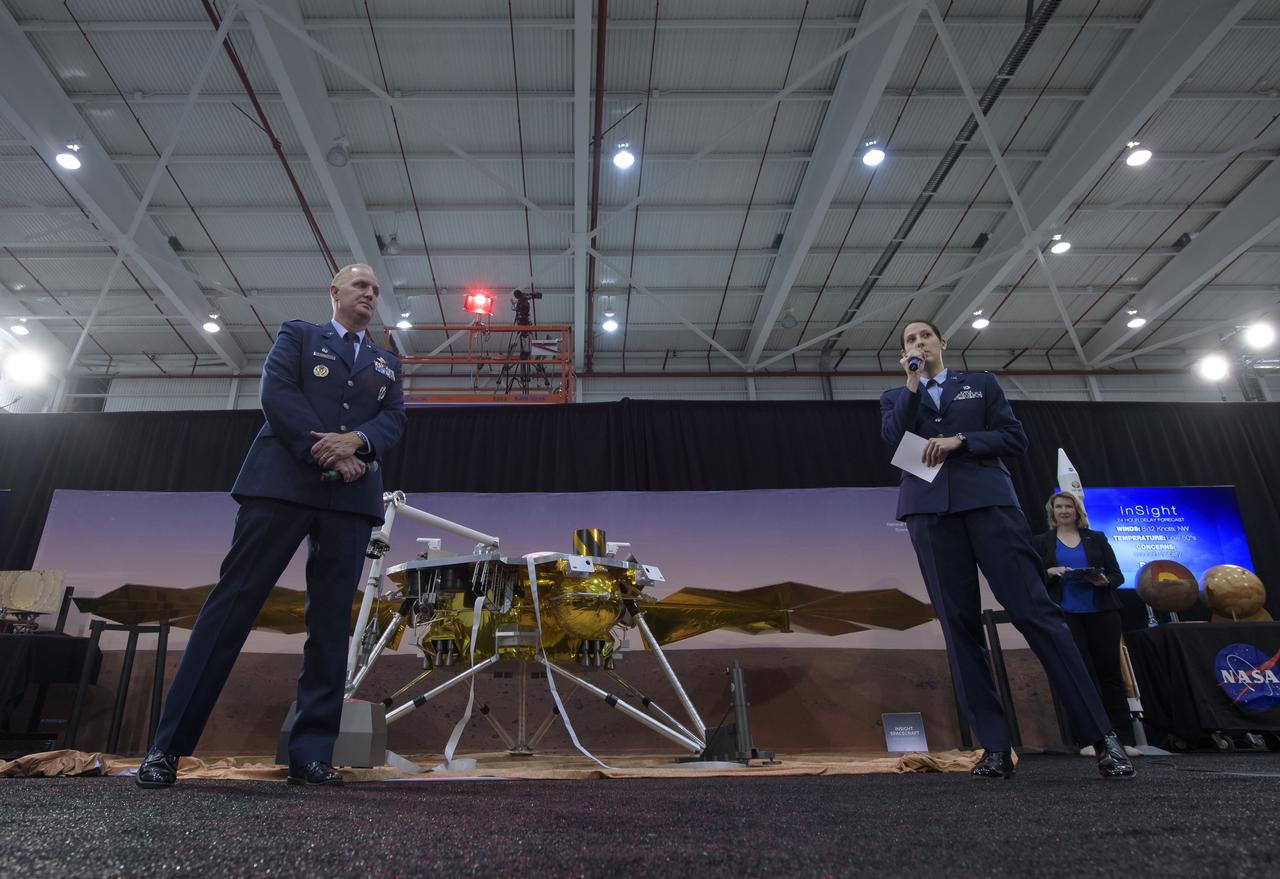
Col. Michael Hough, Commander 30th Space Wing, Vandenberg Air Force Base, left, and 1st Lieutenant Kristina Williams, weather officer, 30th Space Wing, Vandenberg Air Force Base, discuss NASA's InSight mission during a prelaunch media briefing, Thursday, May 3, 2018, at Vandenberg Air Force Base in California. InSight, short for Interior Exploration using Seismic Investigations, Geodesy and Heat Transport, is a Mars lander designed to study the "inner space" of Mars: its crust, mantle, and core. Photo Credit: (NASA/Bill Ingalls)
Long, thin, high-aspect-ratio wings are considered crucial to the design of future long-range aircraft, including fuel-efficient airliners and cargo transports. Unlike the short, stiff wings found on most aircraft today, slender, flexible airfoils are susceptible to uncontrollable vibrations, known as flutter, and may be stressed by bending forces from wind gusts and atmospheric turbulence. To improve ride quality, efficiency, safety, and the long-term health of flexible aircraft structures, NASA is using the X-56A Multi-Utility Technology Testbed (MUTT) to investigate key technologies for active flutter suppression and gust-load alleviation.
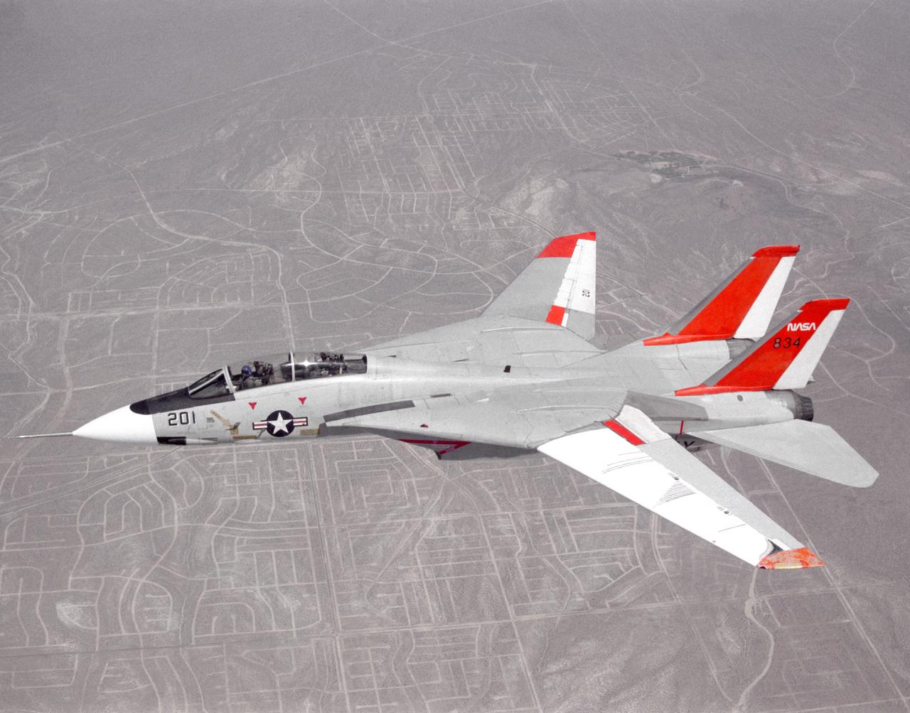
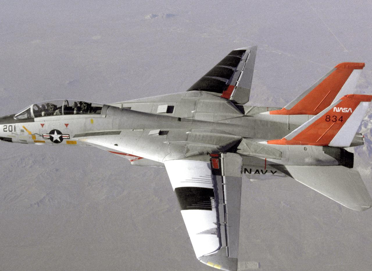
NASA 834, an F-14 Navy Tomcat, seen here in flight, was used at Dryden in 1986 and 1987 in a program known as the Variable-Sweep Transition Flight Experiment (VSTFE). This program explored laminar flow on variable sweep aircraft at high subsonic speeds. An F-14 aircraft was chosen as the carrier vehicle for the VSTFE program primarily because of its variable-sweep capability, Mach and Reynolds number capability, availability, and favorable wing pressure distribution. The variable sweep outer-panels of the F-14 aircraft were modified with natural laminar flow gloves to provide not only smooth surfaces but also airfoils that can produce a wide range of pressure distributions for which transition location can be determined at various flight conditions and sweep angles. Glove I, seen here installed on the upper surface of the left wing, was a "cleanup" or smoothing of the basic F-14 wing, while Glove II was designed to provide specific pressure distributions at Mach 0.7. Laminar flow research continued at Dryden with a research program on the NASA 848 F-16XL, a laminar flow experiment involving a wing-mounted panel with millions of tiny laser cut holes drawing off turbulent boundary layer air with a suction pump.
NASA 834, an F-14 Navy Tomcat, seen here in flight, was used at Dryden in 1986 and 1987 in a program known as the Variable-Sweep Transition Flight Experiment (VSTFE). This program explored laminar flow on variable sweep aircraft at high subsonic speeds. An F-14 aircraft was chosen as the carrier vehicle for the VSTFE program primarily because of its variable-sweep capability, Mach and Reynolds number capability, availability, and favorable wing pressure distribution. The variable sweep outer-panels of the F-14 aircraft were modified with natural laminar flow gloves to provide not only smooth surfaces but also airfoils that can produce a wide range of pressure distributions for which transition location can be determined at various flight conditions and sweep angles. Glove I, seen here installed on the upper surface of the left wing, was a "cleanup" or smoothing of the basic F-14 wing, while Glove II was designed to provide specific pressure distributions at Mach 0.7. Laminar flow research continued at Dryden with a research program on the NASA 848 F-16XL, a laminar flow experiment involving a wing-mounted panel with millions of tiny laser cut holes drawing off turbulent boundary layer air with a suction pump.
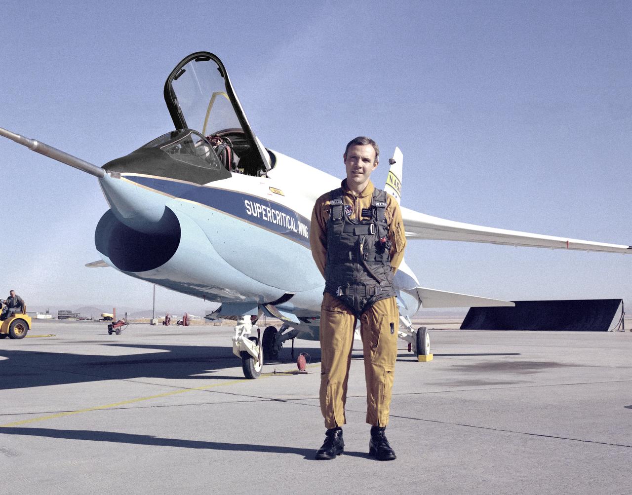
A Vought F-8A Crusader was selected by NASA as the testbed aircraft (designated TF-8A) to install an experimental Supercritical Wing (SCW) in place of the conventional wing. The unique design of the Supercritical Wing reduces the effect of shock waves on the upper surface near Mach 1, which in turn reduces drag. In this photograph the TF-8A Crusader with Supercritical Wing is shown on the ramp with project pilot Tom McMurtry standing beside it. McMurtry received NASA's Exceptional Service Medal for his work on the F-8 SCW aircraft. He also flew the AD-1, F-15 Digital Electronic Engine Control, the KC-130 winglets, the F-8 Digital Fly-By-Wire and other flight research aircraft including the remotely piloted 720 Controlled Impact Demonstration and sub-scale F-15 research projects. In addition, McMurtry was the 747 co-pilot for the Shuttle Approach and Landing Tests and made the last glide flight in the X-24B. McMurtry was Dryden’s Director for Flight Operations from 1986 to 1998, when he became Associate Director for Operations at NASA Dryden. In 1982, McMurtry received the Iven C. Kincheloe Award from the Society of Experimental Test Pilots for his contributions as project pilot on the AD-1 Oblique Wing program. In 1998 he was named as one of the honorees at the Lancaster, Calif., ninth Aerospace Walk of Honor ceremonies. In 1999 he was awarded the NASA Distinguished Service Medal. He retired in 1999 after a distinguished career as pilot and manager at Dryden that began in 1967.
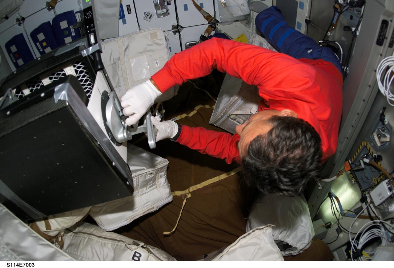
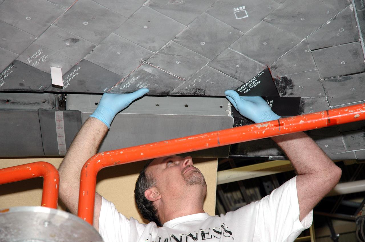
S114-E-7003 (4 August 2005) --- Astronaut Charles J. Camarda, STS-114 mission specialist, performs a middeck evaluation of the mechanical "plug" option for Reinforced Carbon-Carbon (RCC) repair aboard the Space Shuttle Discovery. Camarda used special pre-designated tools to accomplish the procedure, along with round thin, flexible 7-inch-diamter carbon-silicon cover plates designed to flex up to 0.25 inch to conform to the wing leading edge RCC panels, a hardware attachment mechanism similar to a toggle bolt and sealant.
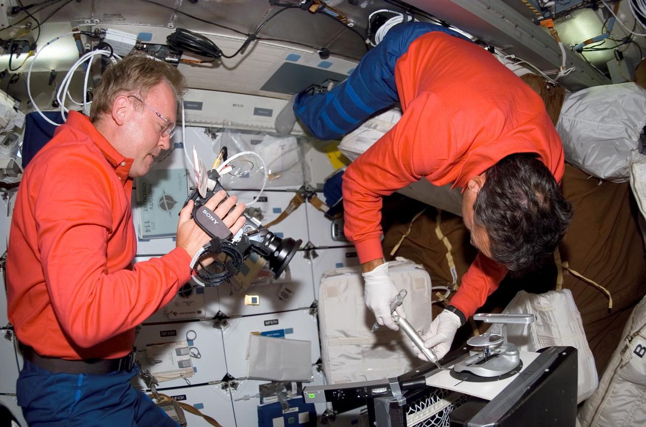
S114-E-7001 (4 August 2005) --- Astronaut Andrew S. W. Thomas, STS-114 mission specialist, photographs a middeck evaluation of the mechanical "plug" option for Reinforced Carbon-Carbon (RCC) repair aboard the Space Shuttle Discovery. Astronaut Charles J. Camarda, mission specialist, uses special pre-designated tools to accomplish the procedure, along with round thin, flexible 7-inch-diamter carbon-silicon cover plates designed to flex up to 0.25 inch to conform to the wing leading edge RCC panels, a hardware attachment mechanism similar to a toggle bolt and sealant.
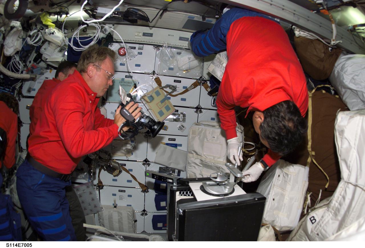
S114-E-7005 (4 August 2005) --- Astronaut Andrew S. W. Thomas, STS-114 mission specialist, photographs a middeck evaluation of the mechanical "plug" option for Reinforced Carbon-Carbon (RCC) repair aboard the Space Shuttle Discovery. Astronaut Charles J. Camarda, mission specialist, uses special pre-designated tools to accomplish the procedure, along with round thin, flexible 7-inch-diamter carbon-silicon cover plates designed to flex up to 0.25 inch to conform to the wing leading edge RCC panels, a hardware attachment mechanism similar to a toggle bolt and sealant.
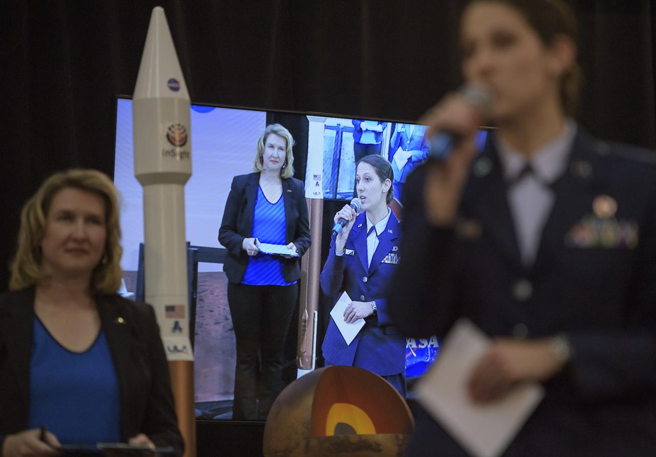
1st Lieutenant Kristina Williams, weather officer, 30th Space Wing, Vandenberg Air Force Base, right, discusses NASA's InSight mission during a prelaunch media briefing, Thursday, May 3, 2018, at Vandenberg Air Force Base in California. InSight, short for Interior Exploration using Seismic Investigations, Geodesy and Heat Transport, is a Mars lander designed to study the "inner space" of Mars: its crust, mantle, and core. Photo Credit: (NASA/Bill Ingalls)
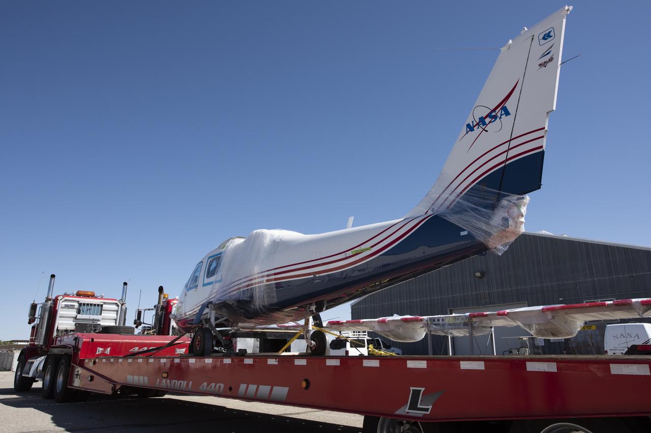
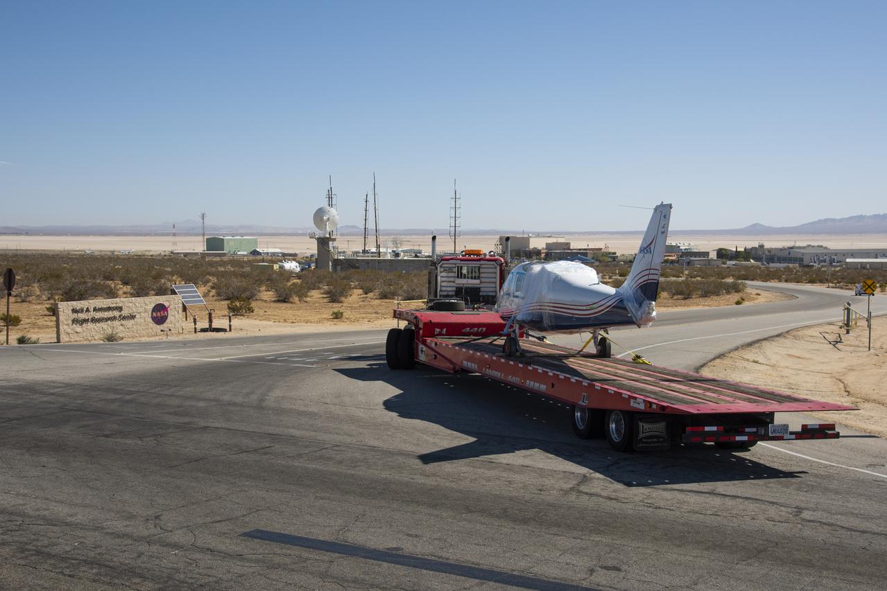
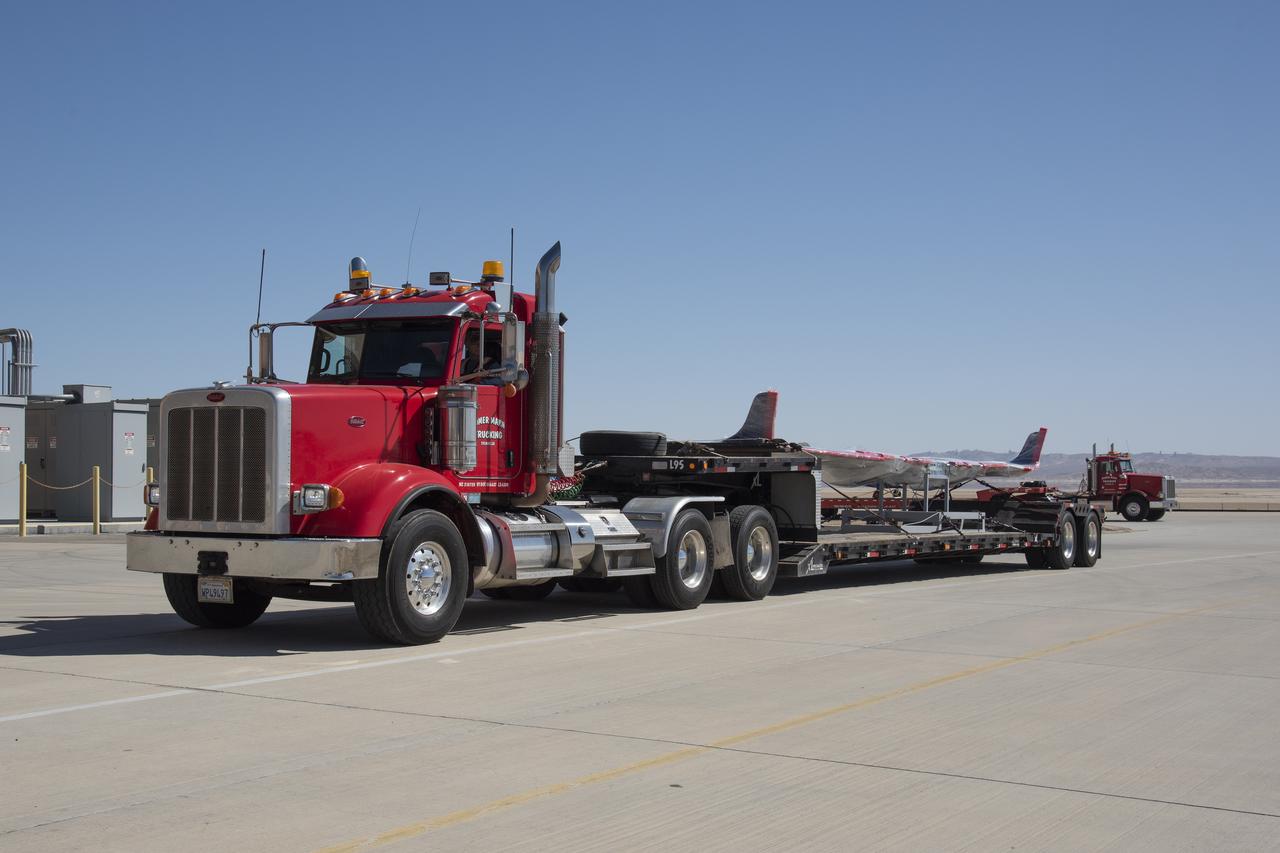
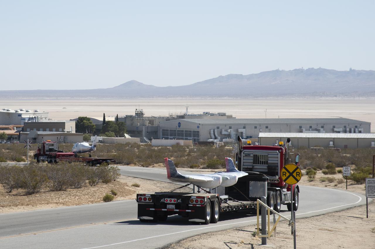
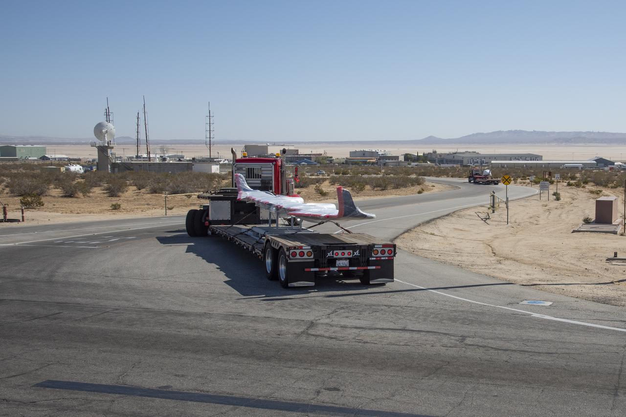
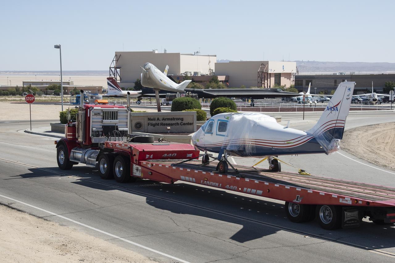
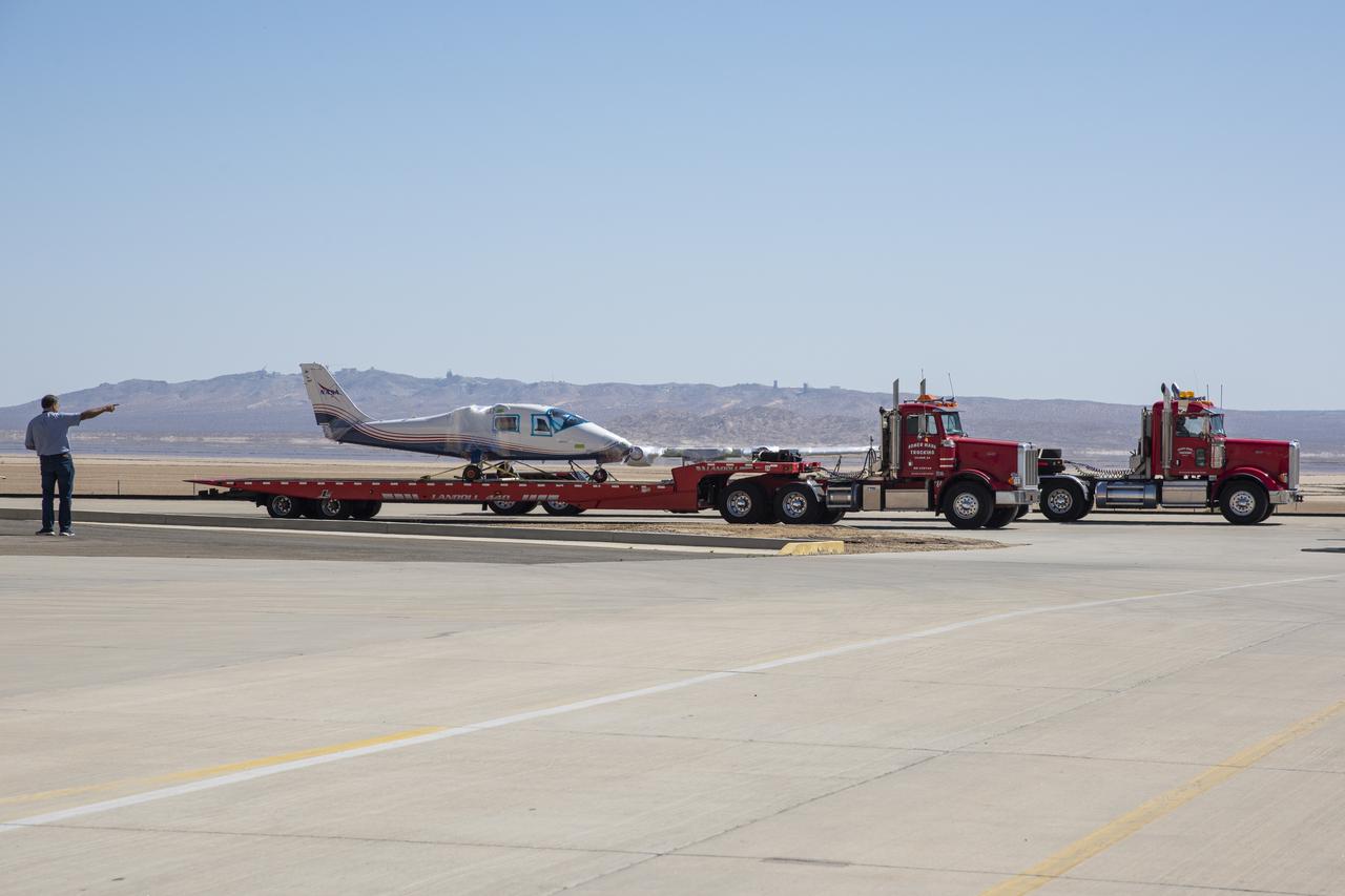
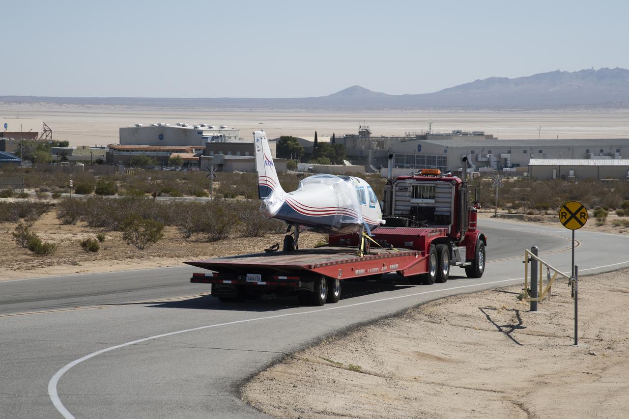
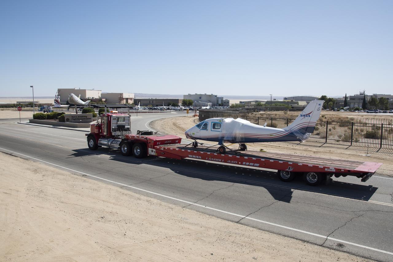
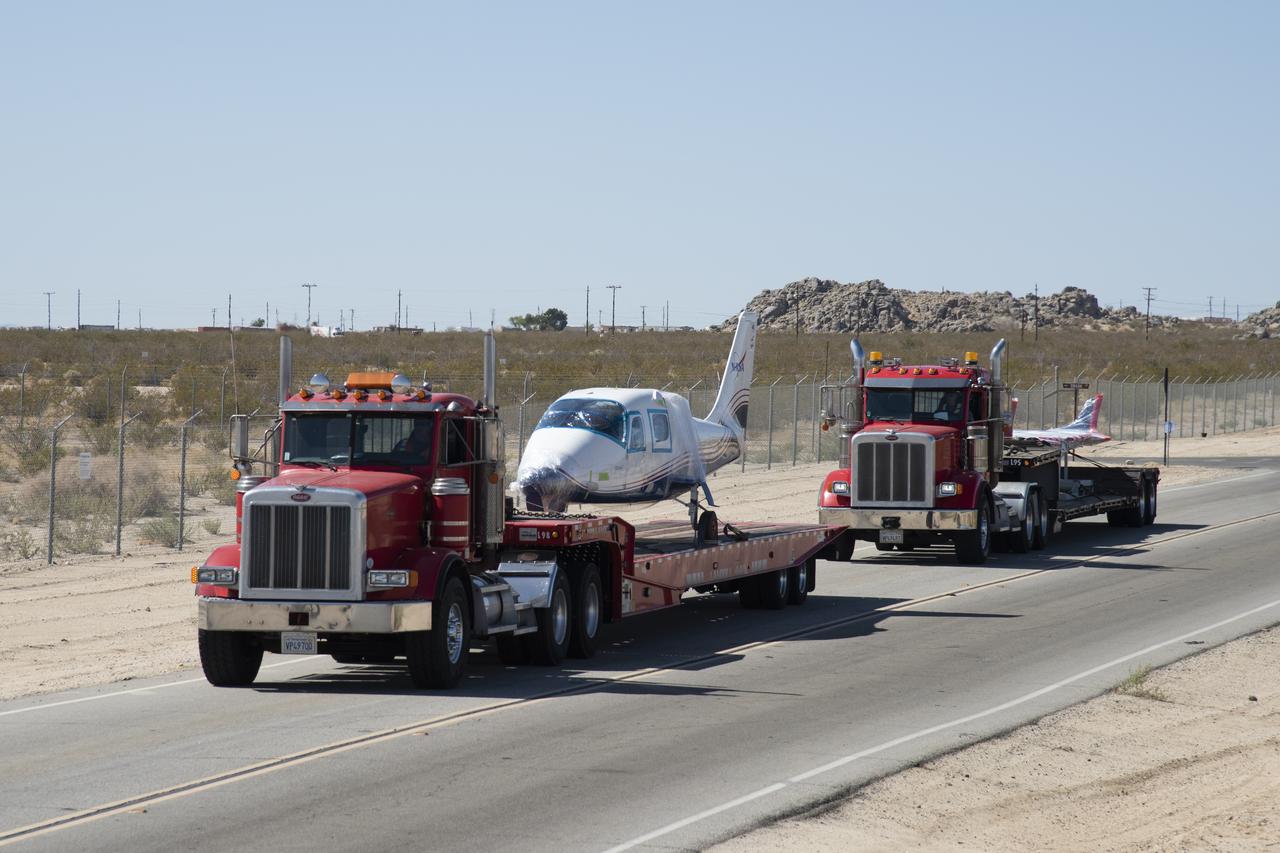
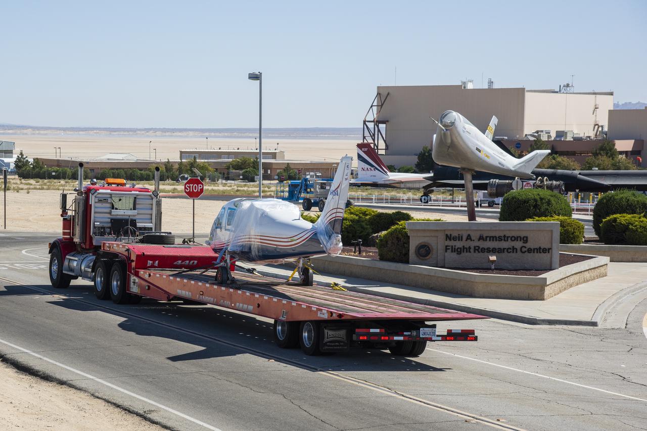
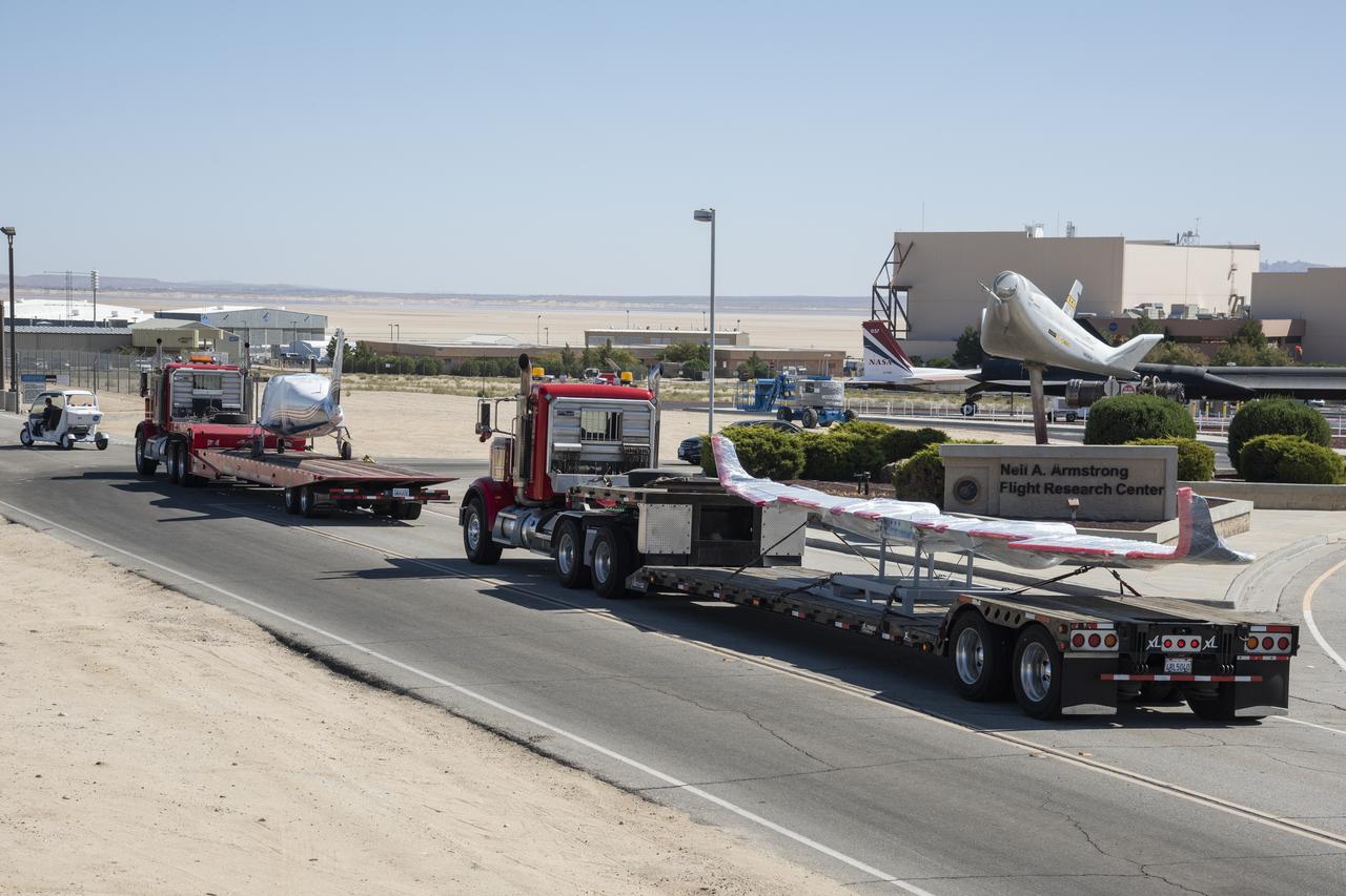
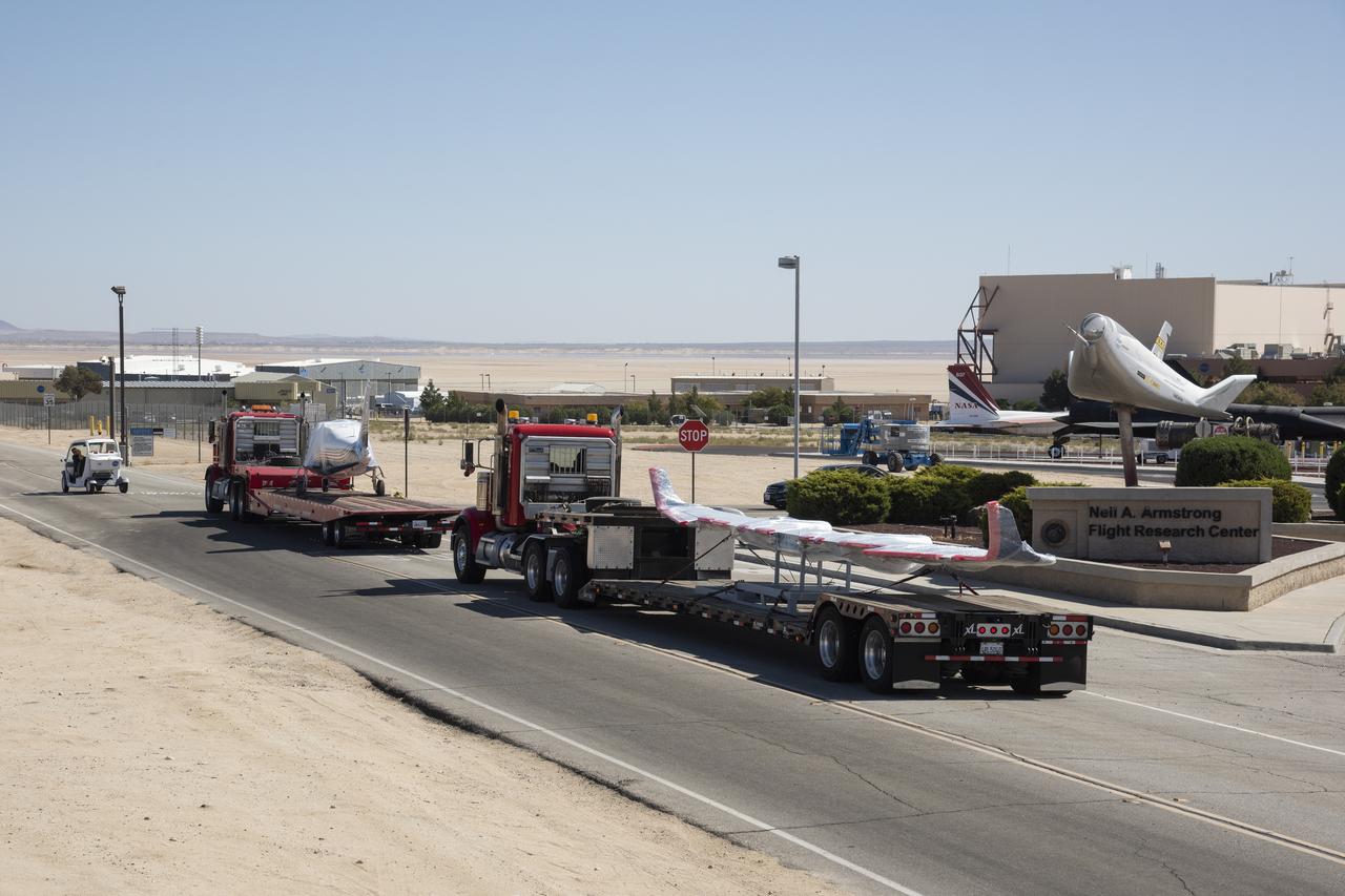
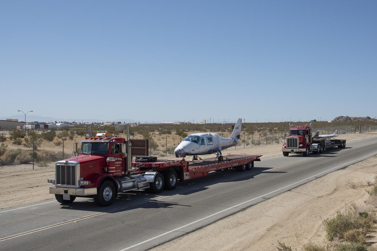
NASA’s all-electric X-57 Maxwell, in its Mod II configuration, arrives at NASA’s Armstrong Flight Research Center in Edwards, California. The X-plane was delivered by prime contractor Empirical Systems Aerospace of San Luis Obispo, California, in two parts, with the wing separated from the fuselage, to aid in a more timely delivery. X-57 is NASA’s first crewed X-plane in two decades, and seeks to further advance the design and airworthiness process for distributed electric propulsion technology for general aviation aircraft.
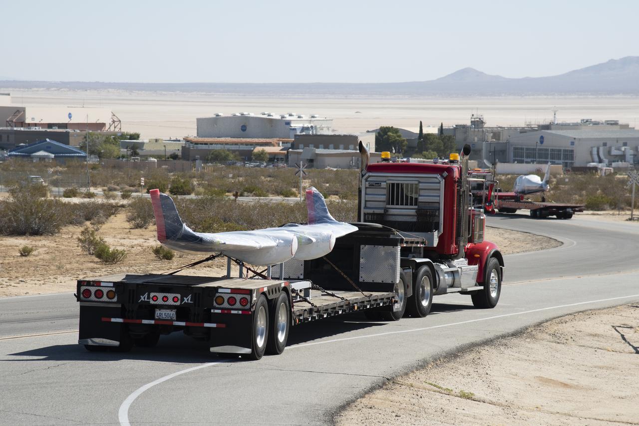
NASA’s all-electric X-57 Maxwell, in its Mod II configuration, arrives at NASA’s Armstrong Flight Research Center in Edwards, California. The X-plane was delivered by prime contractor Empirical Systems Aerospace of San Luis Obispo, California, in two parts, with the wing separated from the fuselage, to aid in a more timely delivery. X-57 is NASA’s first crewed X-plane in two decades, and seeks to further advance the design and airworthiness process for distributed electric propulsion technology for general aviation aircraft.
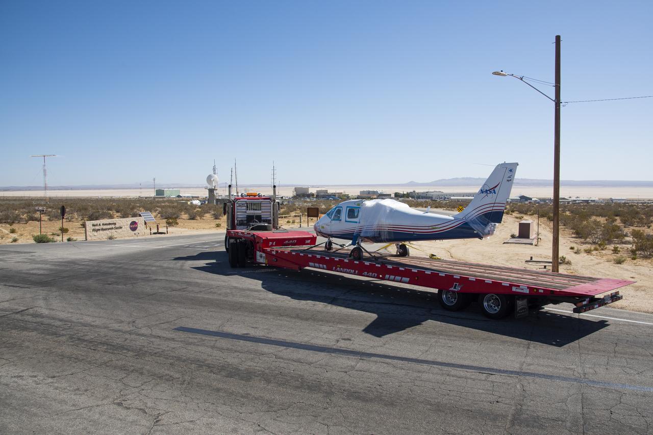
NASA's all-electric X-57 Maxwell, in its Mod II configuration, arrives at NASAâ's Armstrong Flight Research Center in Edwards, California. The X-plane was delivered by prime contractor Empirical Systems Aerospace of San Luis Obispo, California, in two parts, with the wing separated from the fuselage, to aid in a more timely delivery. X-57 is NASA's first crewed X-plane in two decades, and seeks to further advance the design and airworthiness process for distributed electric propulsion technology for general aviation aircraft.
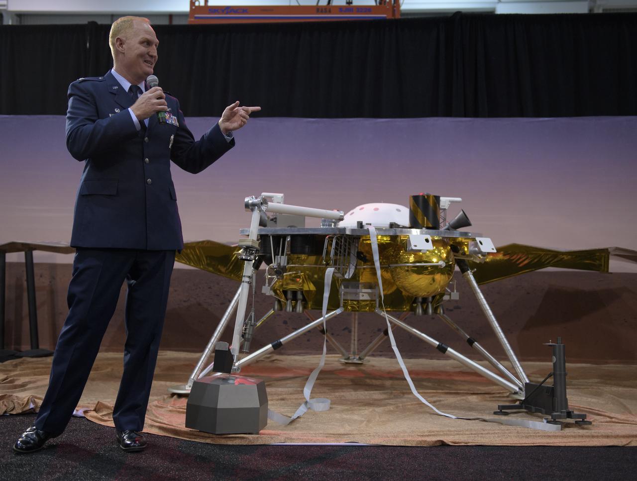
Col. Michael Hough, Commander 30th Space Wing, Vandenberg Air Force Base, discusses NASA's InSight mission during a prelaunch media briefing, Thursday, May 3, 2018, at Vandenberg Air Force Base in California. InSight, short for Interior Exploration using Seismic Investigations, Geodesy and Heat Transport, is a Mars lander designed to study the "inner space" of Mars: its crust, mantle, and core. Photo Credit: (NASA/Bill Ingalls)
NASA's all-electric X-57 Maxwell, in its Mod II configuration, arrives at NASA's Armstrong Flight Research Center in Edwards, California. The X-plane was delivered by prime contractor Empirical Systems Aerospace of San Luis Obispo, California, in two parts, with the wing separated from the fuselage, to aid in a more timely delivery. X-57 is NASA's first crewed X-plane in two decades, and seeks to further advance the design and airworthiness process for distributed electric propulsion technology for general aviation aircraft.
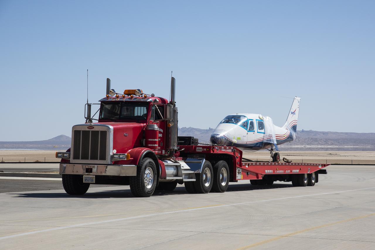
NASA’s all-electric X-57 Maxwell, in its Mod II configuration, arrives at NASA’s Armstrong Flight Research Center in Edwards, California. The X-plane was delivered by prime contractor Empirical Systems Aerospace of San Luis Obispo, California, in two parts, with the wing separated from the fuselage, to aid in a more timely delivery. X-57 is NASA’s first crewed X-plane in two decades, and seeks to further advance the design and airworthiness process for distributed electric propulsion technology for general aviation aircraft.
NASA’s all-electric X-57 Maxwell, in its Mod II configuration, arrives at NASA’s Armstrong Flight Research Center in Edwards, California. The X-plane was delivered by prime contractor Empirical Systems Aerospace of San Luis Obispo, California, in two parts, with the wing separated from the fuselage, to aid in a more timely delivery. X-57 is NASA’s first crewed X-plane in two decades, and seeks to further advance the design and airworthiness process for distributed electric propulsion technology for general aviation aircraft.
NASA's all-electric X-57 Maxwell, in its Mod II configuration, arrives at NASA's Armstrong Flight Research Center in Edwards, California. The X-plane was delivered by prime contractor Empirical Systems Aerospace of San Luis Obispo, California, in two parts, with the wing separated from the fuselage, to aid in a more timely delivery. X-57 is NASA's first crewed X-plane in two decades, and seeks to further advance the design and airworthiness process for distributed electric propulsion technology for general aviation aircraft.
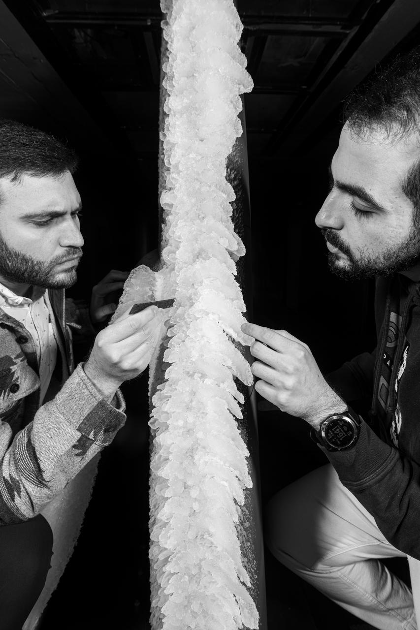
Zaid Sabri and Thomas Ozoroski, Icing Researchers, are shown documenting ice accretion on the leading edge of the next-generation Transonic Truss-Braced Wing design at NASA Glenn's Icing Research Center. This critical research will help understand icing effects for future, high-lift, ultra-efficient aircraft. Photo Credit: (NASA/Jordan Salkin)
NASA's all-electric X-57 Maxwell, in its Mod II configuration, arrives at NASA's Armstrong Flight Research Center in Edwards, California. The X-plane was delivered by prime contractor Empirical Systems Aerospace of San Luis Obispo, California, in two parts, with the wing separated from the fuselage, to aid in a more timely delivery. X-57 is NASA's first crewed X-plane in two decades, and seeks to further advance the design and airworthiness process for distributed electric propulsion technology for general aviation aircraft.
NASA’s all-electric X-57 Maxwell, in its Mod II configuration, arrives at NASA’s Armstrong Flight Research Center in Edwards, California. The X-plane was delivered by prime contractor Empirical Systems Aerospace of San Luis Obispo, California, in two parts, with the wing separated from the fuselage, to aid in a more timely delivery. X-57 is NASA’s first crewed X-plane in two decades, and seeks to further advance the design and airworthiness process for distributed electric propulsion technology for general aviation aircraft.

United States Senator Bob Graham of Florida announces important new federal legislation designed to support the nation's continued space industry development. The announcement was made at Launch Complex 46 at the Cape Canaveral Air Station, the dual-use Navy facility recently modified for commercial launches by the State of Florida. In the background, from left to right, are Hugh Brown, Chairman, Spaceport Florida Authority; Charles Johnson, Athena Program Manager, Lockheed Martin Astronautics; and Col. Ron Larivee, Vice Commander, 45th Space Wing
NASA's all-electric X-57 Maxwell, in its Mod II configuration, arrives at NASA's Armstrong Flight Research Center in Edwards, California. The X-plane was delivered by prime contractor Empirical Systems Aerospace of San Luis Obispo, California, in two parts, with the wing separated from the fuselage, to aid in a more timely delivery. X-57 is NASA's first crewed X-plane in two decades, and seeks to further advance the design and airworthiness process for distributed electric propulsion technology for general aviation aircraft.
NASA's all-electric X-57 Maxwell, in its Mod II configuration, arrives at NASA's Armstrong Flight Research Center in Edwards, California. The X-plane was delivered by prime contractor Empirical Systems Aerospace of San Luis Obispo, California, in two parts, with the wing separated from the fuselage, to aid in a more timely delivery. X-57 is NASA's first crewed X-plane in two decades, and seeks to further advance the design and airworthiness process for distributed electric propulsion technology for general aviation aircraft.
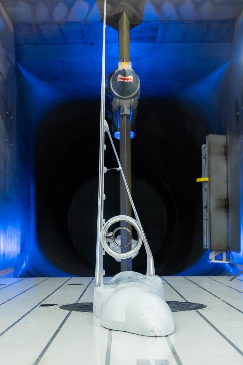
NASA’s Sustainable Flight Demonstrator project concluded wind tunnel testing in the fall of 2024. Tests on a Boeing-built X-66 model were completed at NASA’s Ames Research Center in California’s Silicon Valley in the 11-Foot Transonic Unitary Plan Facility. The model underwent tests representing expected flight conditions to obtain engineering information to influence design of the wing and provide data for flight simulators.
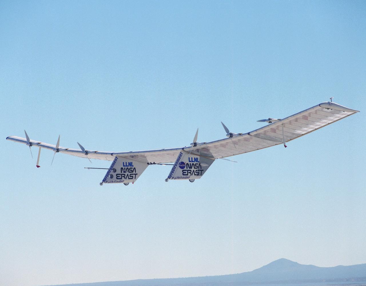
The Pathfinder solar-powered remotely piloted aircraft climbs to a record-setting altitude of 50,567 feet during a flight Sept. 11, 1995, at NASA's Dryden Flight Research Center, Edwards, California. The flight was part of the NASA ERAST (Environmental Research Aircraft and Sensor Technology) program. The Pathfinder was designed and built by AeroVironment Inc., Monrovia, California. Solar arrays cover nearly all of the upper wing surface and produce electricity to power the aircraft's six motors.
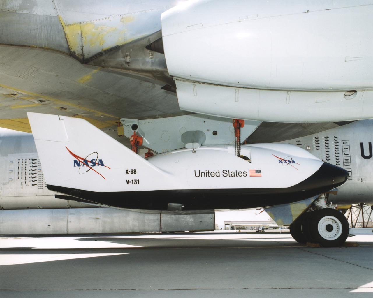
A close-up view of the X-38 research vehicle mounted under the wing of the B-52 mothership prior to a 1997 test flight. The X-38, which was designed to help develop technology for an emergency crew return vehicle (CRV) for the International Space Station, is one of many research vehicles the B-52 has carried aloft over the past 40 years.
NASA's all-electric X-57 Maxwell, in its Mod II configuration, arrives at NASA's Armstrong Flight Research Center in Edwards, California. The X-plane was delivered by prime contractor Empirical Systems Aerospace of San Luis Obispo, California, in two parts, with the wing separated from the fuselage, to aid in a more timely delivery. X-57 is NASA's first crewed X-plane in two decades, and seeks to further advance the design and airworthiness process for distributed electric propulsion technology for general aviation aircraft.
NASA's all-electric X-57 Maxwell, in its Mod II configuration, arrives at NASA's Armstrong Flight Research Center in Edwards, California. The X-plane was delivered by prime contractor Empirical Systems Aerospace of San Luis Obispo, California, in two parts, with the wing separated from the fuselage, to aid in a more timely delivery. X-57 is NASA's first crewed X-plane in two decades, and seeks to further advance the design and airworthiness process for distributed electric propulsion technology for general aviation aircraft.
NASA's all-electric X-57 Maxwell, in its Mod II configuration, arrives at NASA's Armstrong Flight Research Center in Edwards, California. The X-plane was delivered by prime contractor Empirical Systems Aerospace of San Luis Obispo, California, in two parts, with the wing separated from the fuselage, to aid in a more timely delivery. X-57 is NASA's first crewed X-plane in two decades, and seeks to further advance the design and airworthiness process for distributed electric propulsion technology for general aviation aircraft.
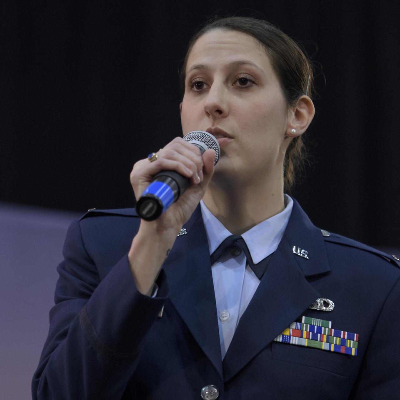
1st Lieutenant Kristina Williams, weather officer, 30th Space Wing, Vandenberg Air Force Base, discusses NASA's InSight mission during a prelaunch media briefing, Thursday, May 3, 2018, at Vandenberg Air Force Base in California. InSight, short for Interior Exploration using Seismic Investigations, Geodesy and Heat Transport, is a Mars lander designed to study the "inner space" of Mars: its crust, mantle, and core. Photo Credit: (NASA/Bill Ingalls)
KENNEDY SPACE CENTER, FLA. - A worker in the Orbiter Processing Facility installs a new carrier panel on the orbiter Discovery. The new panel has an added thermal barrier that performs as a flow restrictor to further protect the wing leading edges. The panels fit between the Reinforced Carbon Carbon panel and the vehicle. The change is one of the safety features for return to flight. Discovery is the orbiter designated for the Return to Flight mission, STS-114. The launch window is May 12 to June 3, 2005.
NASA’s all-electric X-57 Maxwell, in its Mod II configuration, arrives at NASA’s Armstrong Flight Research Center in Edwards, California. The X-plane was delivered by prime contractor Empirical Systems Aerospace of San Luis Obispo, California, in two parts, with the wing separated from the fuselage, to aid in a more timely delivery. X-57 is NASA’s first crewed X-plane in two decades, and seeks to further advance the design and airworthiness process for distributed electric propulsion technology for general aviation aircraft.
NASA's all-electric X-57 Maxwell, in its Mod II configuration, arrives at NASA's Armstrong Flight Research Center in Edwards, California. The X-plane was delivered by prime contractor Empirical Systems Aerospace of San Luis Obispo, California, in two parts, with the wing separated from the fuselage, to aid in a more timely delivery. X-57 is NASA's first crewed X-plane in two decades, and seeks to further advance the design and airworthiness process for distributed electric propulsion technology for general aviation aircraft.
NASA's all-electric X-57 Maxwell, in its Mod II configuration, arrives at NASA's Armstrong Flight Research Center in Edwards, California. The X-plane was delivered by prime contractor Empirical Systems Aerospace of San Luis Obispo, California, in two parts, with the wing separated from the fuselage, to aid in a more timely delivery. X-57 is NASA's first crewed X-plane in two decades, and seeks to further advance the design and airworthiness process for distributed electric propulsion technology for general aviation aircraft.
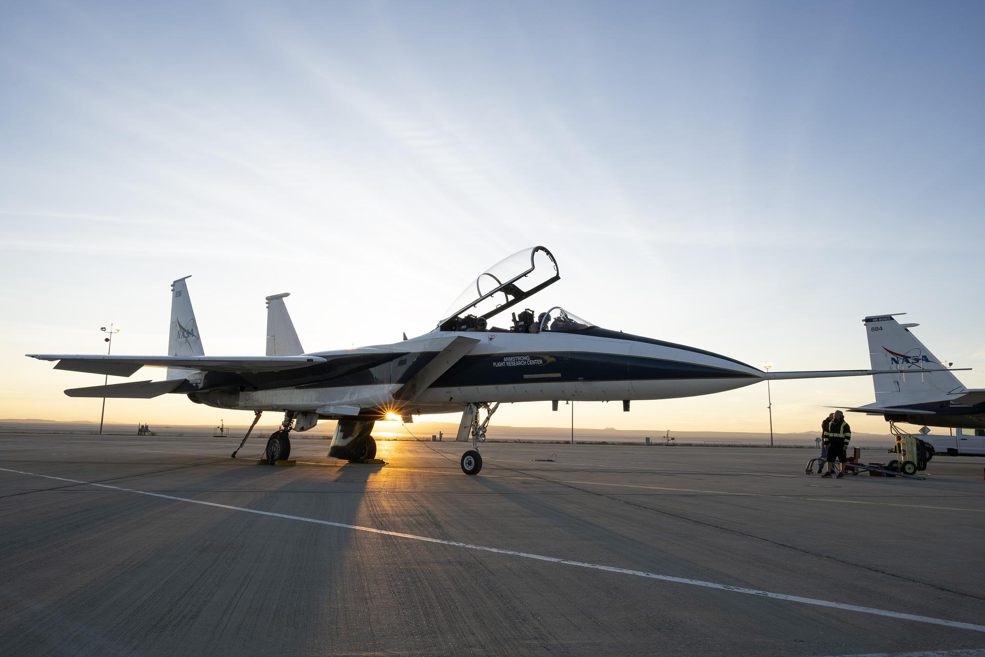
An F-15 research aircraft sits on the ramp at NASA’s Armstrong Flight Research Center in Edwards, California, on Tuesday, March 17, 2026. NASA pilots Jim Less, front seat, and Carrie Worth prepare for the flight. The agency’s Crossflow Attenuated Natural Laminar Flow (CATNLF) test article is attached to the bottom of the F-15. The project aims to lower fuel costs for future commercial aircraft by testing a scale-model wing designed to improve laminar flow.
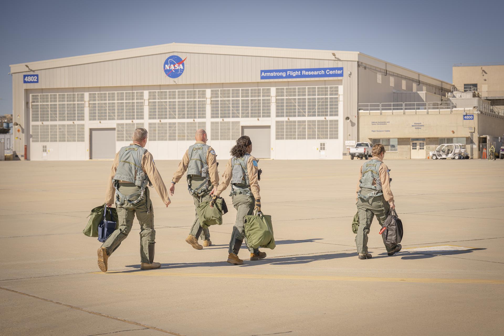
Four NASA employees walk toward a hangar after a flight Thursday, Feb. 4, 2026, at NASA’s Armstrong Flight Research Center in Edwards, California. The team supports the agency’s Crossflow Attenuated Natural Laminar Flow (CATNLF) project, which aims to lower fuel costs for future commercial aircraft by testing a scale-model wing designed to improve laminar flow.

NASA researchers Mike Frederick, right, and Michelle Banchy, left, along with Ashante Jordan and intern Phillip Nguyen, sit in a control room and prepare for a flight test Thursday, Jan. 29, 2026, at NASA’s Armstrong Flight Research Center in Edwards, California. The agency’s Crossflow Attenuated Natural Laminar Flow (CATNLF) project aims to lower fuel costs for future commercial aircraft by testing a scale-model wing designed to improve laminar flow.
NASA flight test engineer A.J. Jaffe and pilot Nils Larson walk on the ramp before a flight Tuesday, Jan. 13, 2026, at NASA’s Armstrong Flight Research Center in Edwards, California. The two support the agency’s Crossflow Attenuated Natural Laminar Flow (CATNLF) project, which aims to lower fuel costs for future commercial aircraft by testing a scale-model wing designed to improve laminar flow.

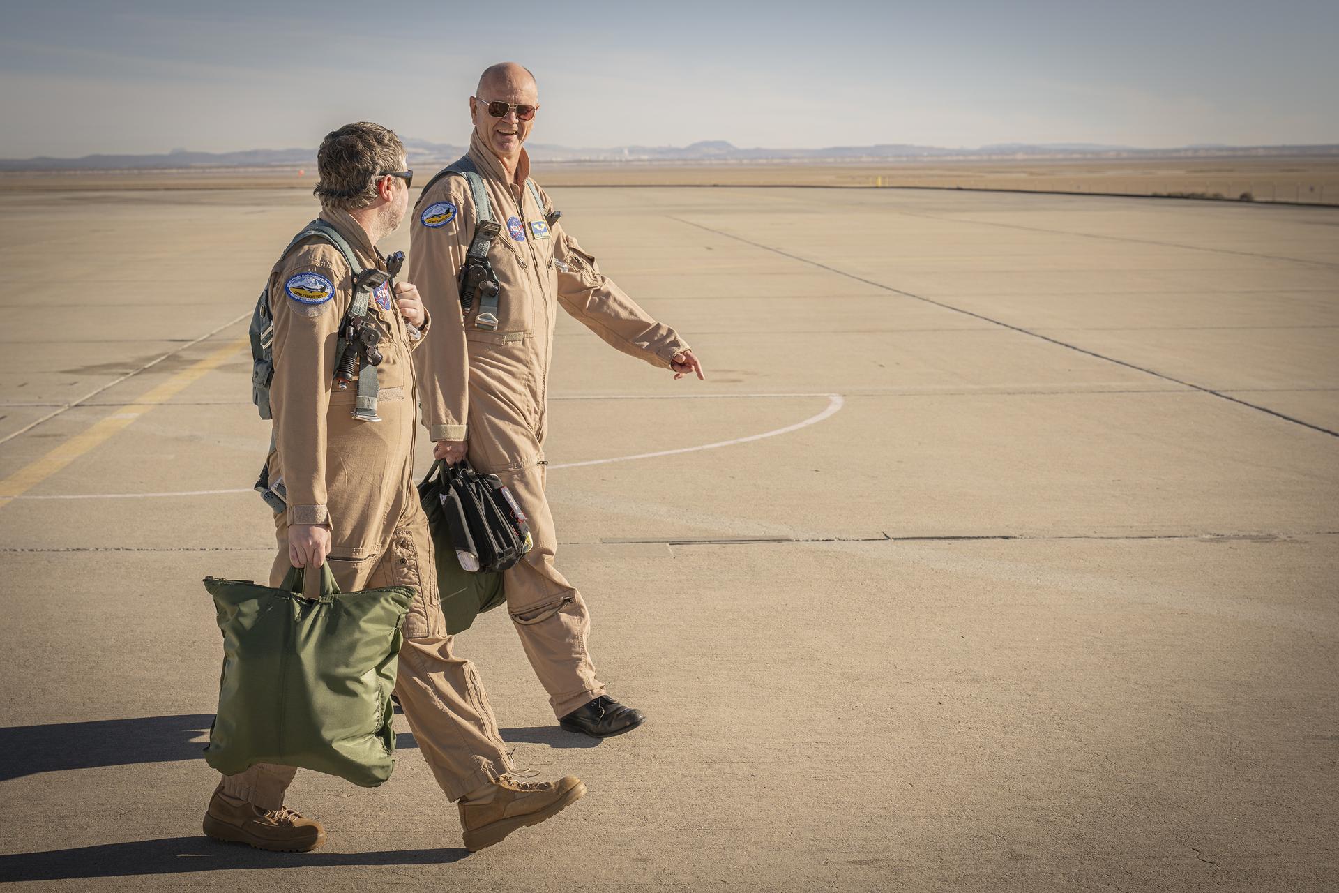
NASA test pilots Jim Less, left, and Nils Larson walk away from a hangar at NASA’s Armstrong Flight Research Center in Edwards, California, on Thursday, Feb. 4, 2026. The pilots support the agency’s Crossflow Attenuated Natural Laminar Flow (CATNLF) project, which aims to lower fuel costs for future commercial aircraft by testing a scale-model wing designed to improve laminar flow.

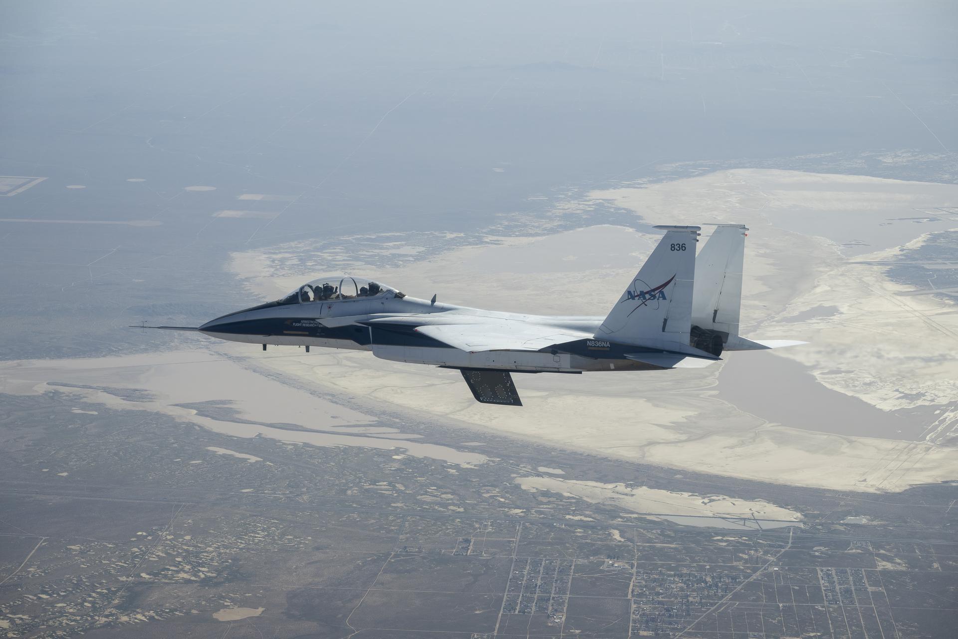
An F-15 aircraft flies above the world’s largest compass rose above NASA’s Armstrong Flight Research Center in Edwards, California, on Monday, April 20, 2026. NASA’s Crossflow Attenuated Natural Laminar Flow (CATNLF) test article is attached to the bottom of the F-15. The project aims to lower fuel costs for future commercial aircraft by testing a scale-model wing designed to improve laminar flow.

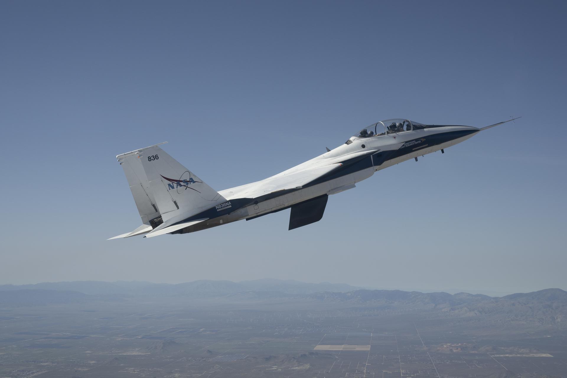
A F-15 aircraft owned by NASA’s Armstrong Flight Research Center in Edwards, California, flies above a mountain range on Tuesday, April 21, 2026. The agency’s Crossflow Attenuated Natural Laminar Flow (CATNLF) test article is attached to the bottom of this F-15. This project aims to lower fuel costs for future commercial aircraft by testing a scale-model wing designed to improve laminar flow.
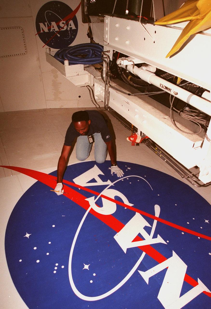
A KSC worker paints the NASA logo on the port wing of the orbiter Endeavour, which is scheduled to launch in December for STS-88. The paint is a special pigment that takes 18 hours to dry; the whole process takes approximately two weeks to complete. The NASA logo, termed "meatball," was originally designed in the late 1950s. It symbolized NASA’s role in aeronautics and space in the early years of the agency. The original design included a white border surrounding it. The border was dropped for the Apollo 7 mission in October 1968, replaced with royal blue to match the background of the emblem. In 1972 the logo was replaced by a simple and contemporary design the "worm" which was retired from use last year. NASA reverted to its original logo in celebration of the agency’s 40th anniversary in October, and the "golden age" of America’s space program. All the orbiters will bear the new logo
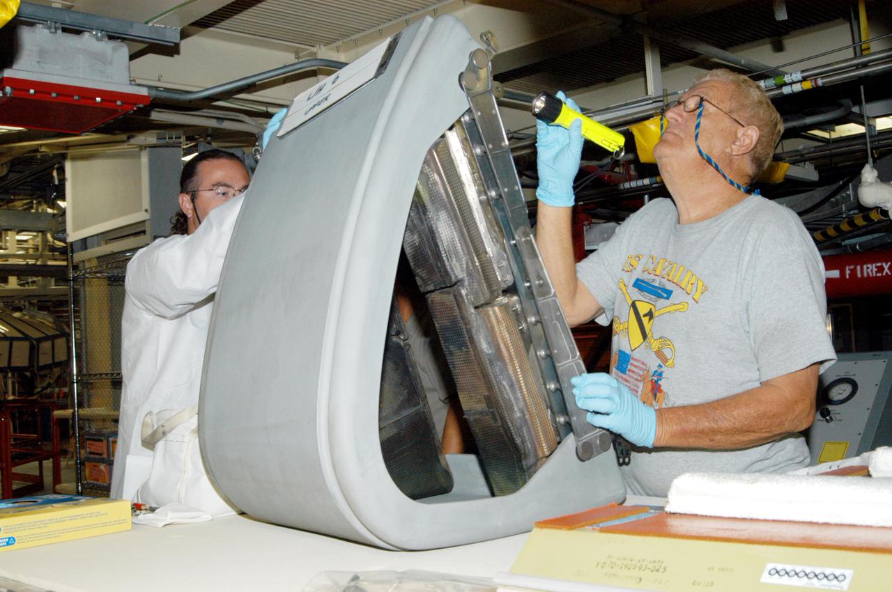
KENNEDY SPACE CENTER, FLA. - In the Orbiter Processing Facility, Matt Scott and Mel Romans (left and right), with United Space Alliance, closely inspect the final Reinforced Carbon-Carbon (RCC) panel to be installed on orbiter Discovery’s left wing. The leading edges of each of an orbiter’s wings have 22 RCC panels. They are light gray and made entirely of carbon composite material, which protect the orbiter during re-entry. The molded components are approximately 0.25- to 0.5-inch thick and capable of withstanding temperatures up to 3,220 degrees F. Following the Columbia accident in February 2002, which was caused by a breach in an RCC panel that allowed hot gases into the vehicle, each panel on Discovery was removed and thoroughly inspected before final reinstallation. Discovery is the designated orbiter to fly on the Return to Flight mission STS-114, the first Space Shuttle to launch since the accident. The launch window for the mission is May 12 to June 3, 2005.
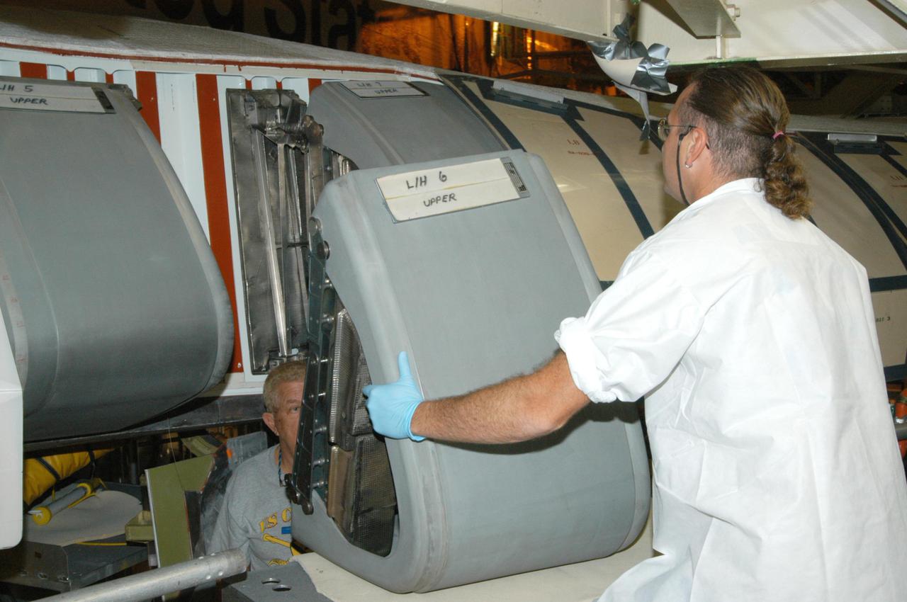
KENNEDY SPACE CENTER, FLA. - Matt Scott, with United Space Alliance, lifts the final Reinforced Carbon-Carbon (RCC) panel into position for installation on orbiter Discovery’s left wing. The leading edges of each of an orbiter’s wings have 22 RCC panels. They are light gray and made entirely of carbon composite material, which protect the orbiter during re-entry. The molded components are approximately 0.25- to 0.5-inch thick and capable of withstanding temperatures up to 3,220 degrees F. Following the Columbia accident in February 2002, which was caused by a breach in an RCC panel that allowed hot gases into the vehicle, each panel on Discovery was removed and thoroughly inspected before final reinstallation. Discovery is the designated orbiter to fly on the Return to Flight mission STS-114, the first Space Shuttle to launch since the accident. The launch window for the mission is May 12 to June 3, 2005.
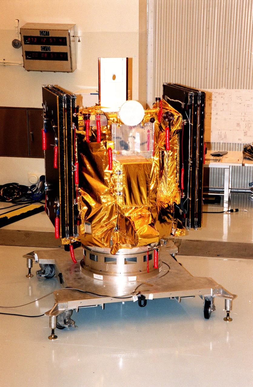
KENNEDY SPACE CENTER, FLA. -- Deep Space 1 rests on its work platform after being fitted with thermal insulation. The reflective insulation is designed to protect the spacecraft as this side faces the sun. At either side of the spacecraft are its solar wings, folded for launch. When fully extended, the wings measure 38.6 feet from tip to tip. The first flight in NASA's New Millennium Program, Deep Space 1 is designed to validate 12 new technologies for scientific space missions of the next century. Onboard experiments include a solar-powered ion propulsion engine and software that tracks celestial bodies so the spacecraft can make its own navigation decisions without the intervention of ground controllers. The ion propulsion engine is the first non-chemical propulsion to be used as the primary means of propelling a spacecraft. Deep Space 1 will complete most of its mission objectives within the first two months, but may also do a flyby of a near-Earth asteroid, 1992 KD, in July 1999. Deep Space 1 will be launched aboard a Boeing Delta 7326 rocket from Launch Pad 17A, Cape Canaveral Air Station, in October. Delta II rockets are medium capacity expendable launch vehicles derived from the Delta family of rockets built and launched since 1960. Since then there have been more than 245 Delta launches
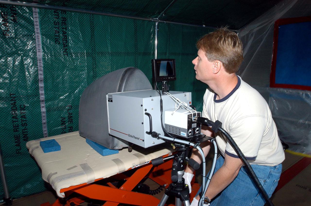
KENNEDY SPACE CENTER, FLA. - Jim Landy, NDE specialist with United Space Alliance (USA), examines a Reinforced Carbon Carbon panel using flash thermography. A relatively new procedure at KSC, thermography uses high intensity light to heat areas of the panels. The panels are then immediately scanned with an infrared camera. As the panels cool, any internal flaws are revealed. The gray carbon composite RCC panels are attached to the leading edge of the wing of the orbiters. They have sufficient strength to withstand the aerodynamic forces experienced during launch and reentry, which can reach as high as 800 pounds per square foot. The operating range of RCC is from minus 250º F to about 3,000º F, the temperature produced by friction with the atmosphere during reentry. The panels will be installed on the orbiter Discovery, designated for the first Return to Flight mission, STS-114.
KENNEDY SPACE CENTER, FLA. - Jim Landy, NDE specialist with USA, points to an area of a Reinforced Carbon Carbon panel just examined using flash thermography. A relatively new procedure at KSC, thermography uses high intensity light to heat areas of the panels. The panels are then immediately scanned with an infrared camera. As the panels cool, any internal flaws are revealed. The gray carbon composite RCC panels are attached to the leading edge of the wing of the orbiters. They have sufficient strength to withstand the aerodynamic forces experienced during launch and reentry, which can reach as high as 800 pounds per square foot. The operating range of RCC is from minus 250º F to about 3,000º F, the temperature produced by friction with the atmosphere during reentry. The panels will be installed on the orbiter Discovery, designated for the first Return to Flight mission, STS-114.