
Veterans of the X-15 flight research program, most of them now retired, reunited at Dryden on the 40th anniversary of the last X-15 flight on Oct. 24, 1968 for a historical colloquium on the X-15 by noted aerospace historian and author Dennis Jenkins on Oct. 24, 2008. Gathered in front of the replica of X-15 #3 the were (from left) Johnny Armstrong, Betty Love, Paul Reukauf, Bob Hoey, Dave Stoddard, Dean Webb, Vince Capasso, Bill Dana (who flew the last flight), John McTigue and T.D. Barnes. Jenkins, the author of "X-15: Extending the Frontiers of Flight," maintained during his presentation that despite setbacks, the X-15 program became the most successful of all the X-plane research programs due to the can-do, fix-the-problem and go-fly-again attitude of the X-15's cadre of engineers and technicians.
Joseph A. Walker was a Chief Research Pilot at the NASA Dryden Flight Research Center during the mid-1960s. He joined the NACA in March 1945, and served as project pilot at the Edwards flight research facility on such pioneering research projects as the D-558-1, D-558-2, X-1, X-3, X-4, X-5, and the X-15. He also flew programs involving the F-100, F-101, F-102, F-104, and the B-47. Walker made the first NASA X-15 flight on March 25, 1960. He flew the research aircraft 24 times and achieved its fastest speed and highest altitude. He attained a speed of 4,104 mph (Mach 5.92) during a flight on June 27, 1962, and reached an altitude of 354,300 feet on August 22, 1963 (his last X-15 flight). He was the first man to pilot the Lunar Landing Research Vehicle (LLRV) that was used to develop piloting and operational techniques for lunar landings. Walker was born February 20, 1921, in Washington, Pa. He lived there until graduating from Washington and Jefferson College in 1942, with a B.A. degree in Physics. During World War II he flew P-38 fighters for the Air Force, earning the Distinguished Flying Cross and the Air Medal with Seven Oak Clusters. Walker was the recipient of many awards during his 21 years as a research pilot. These include the 1961 Robert J. Collier Trophy, 1961 Harmon International Trophy for Aviators, the 1961 Kincheloe Award and 1961 Octave Chanute Award. He received an honorary Doctor of Aeronautical Sciences degree from his alma mater in June of 1962. Walker was named Pilot of the Year in 1963 by the National Pilots Association. He was a charter member of the Society of Experimental Test Pilots, and one of the first to be designated a Fellow. He was fatally injured on June 8, 1966, in a mid-air collision between an F-104 he was piloting and the XB-70.
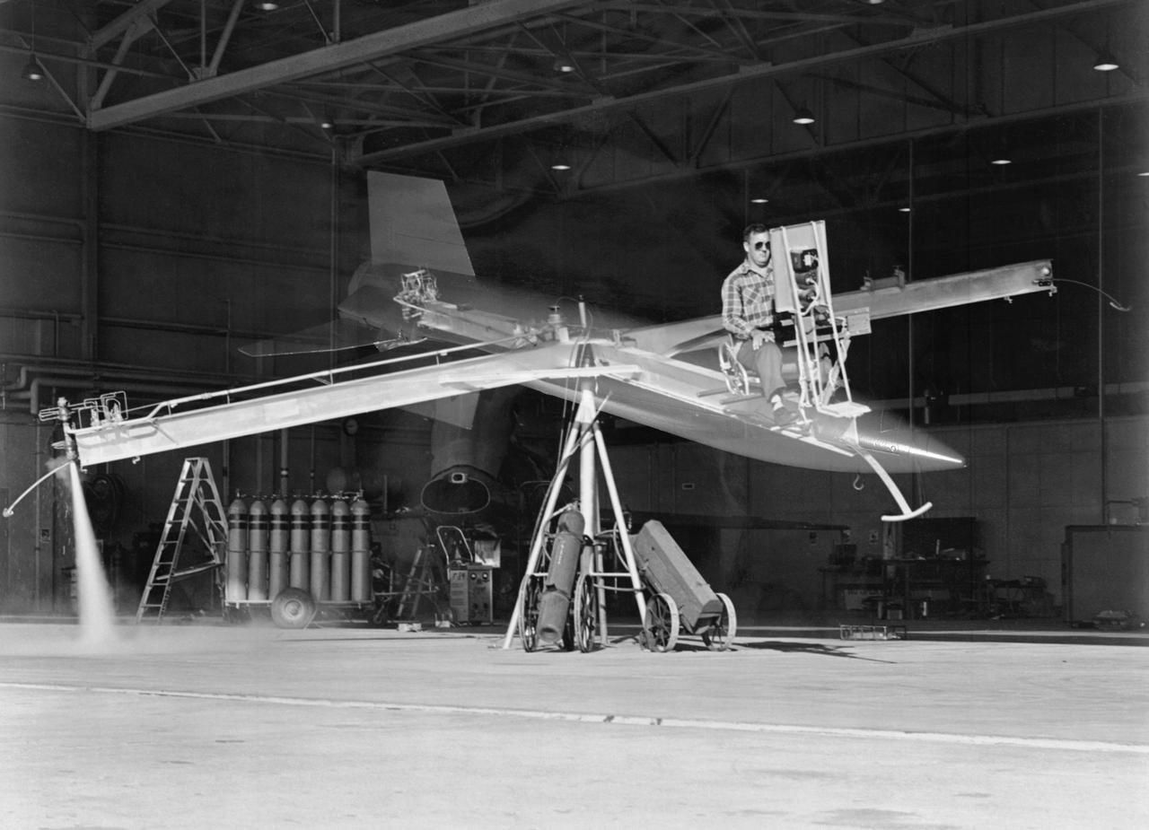
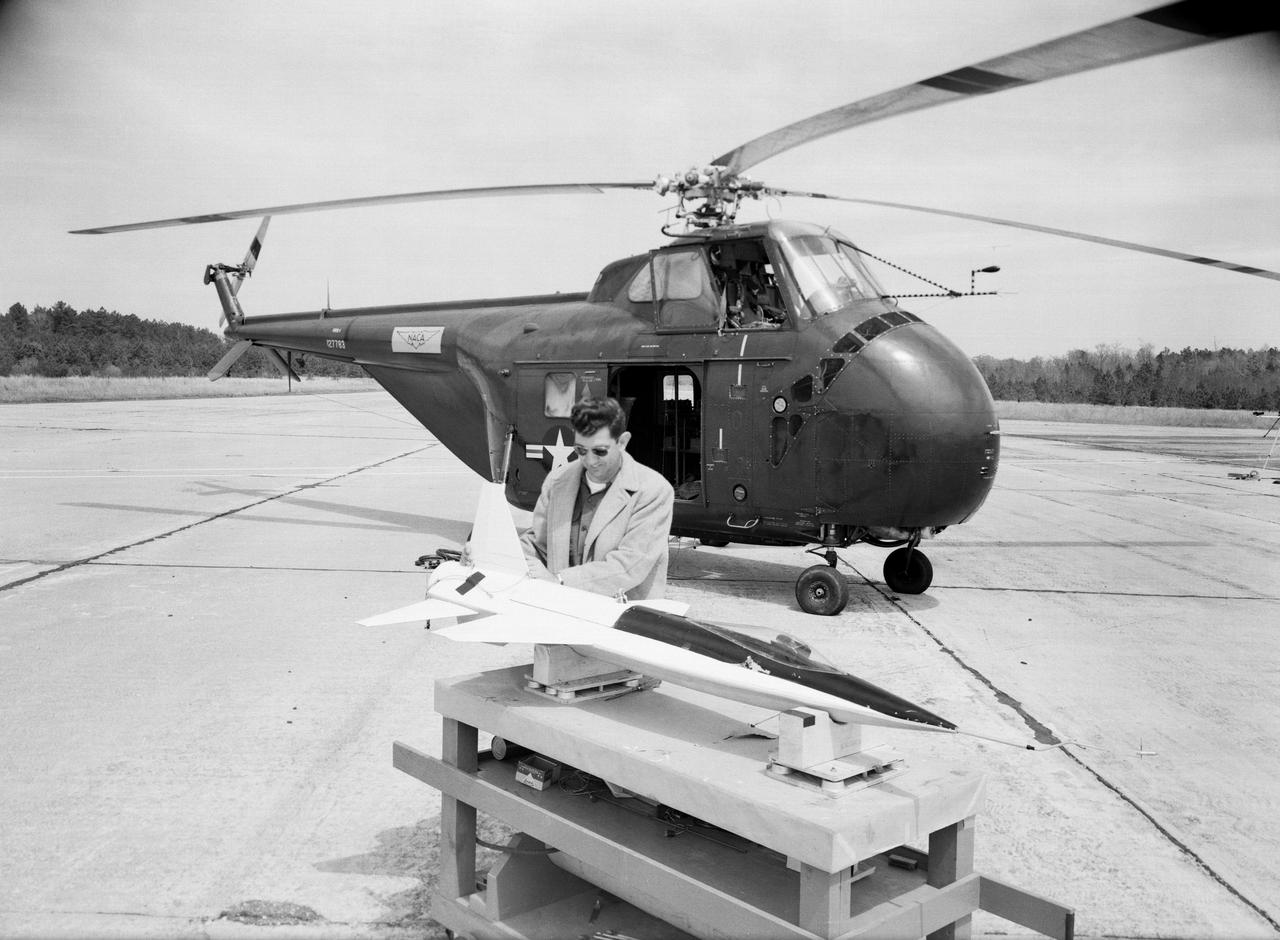
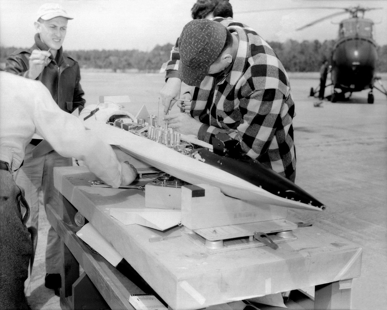
Attitude control simulator for X-15 studies at Langley, 1958. Photograph published in Engineer in Charge: A History of the Langley Aeronautical Laboratory, 1917-1958 by James R. Hansen (page 367).
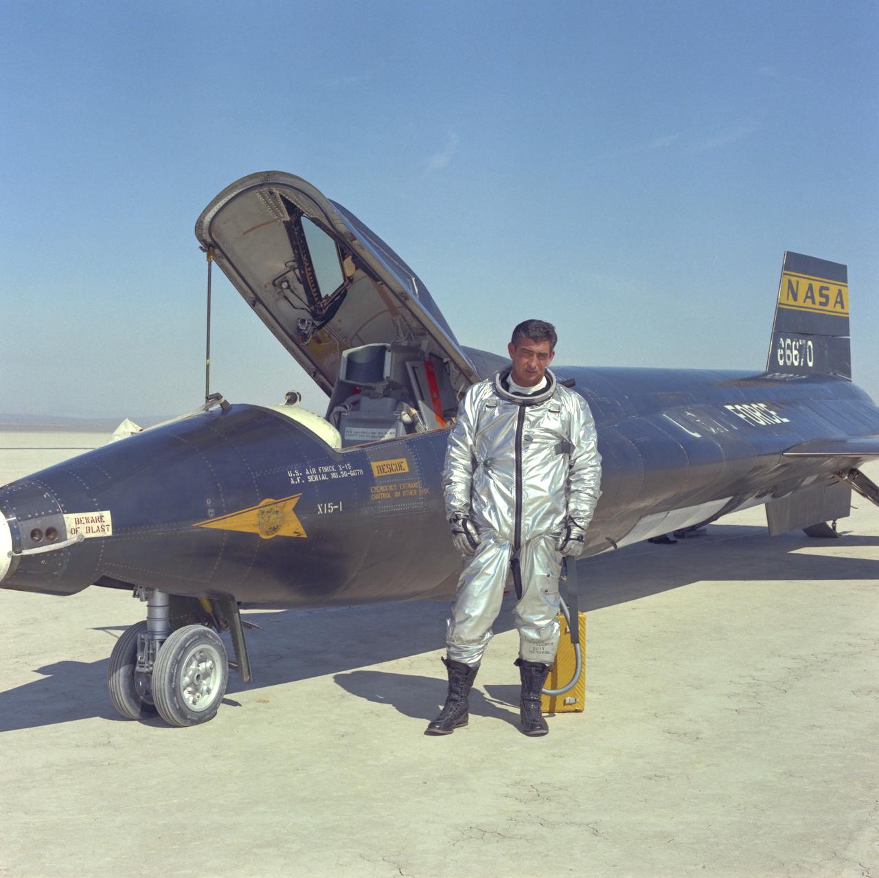
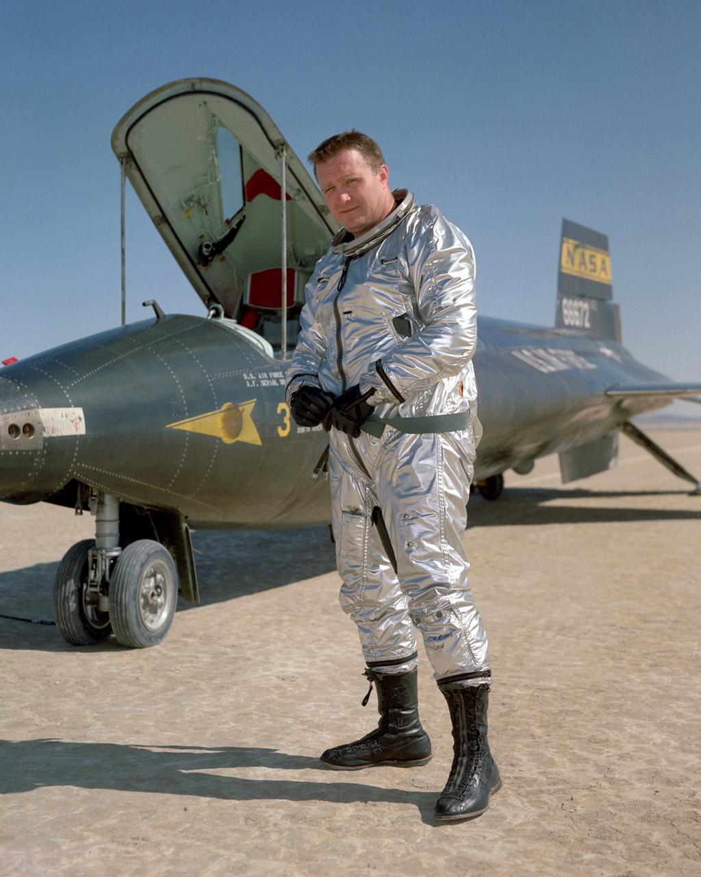
Air Force pilot Mike Adams poses in front of X-15-#1 after flight on Rogers Dry Lake at Edwards Air Force Base in California.
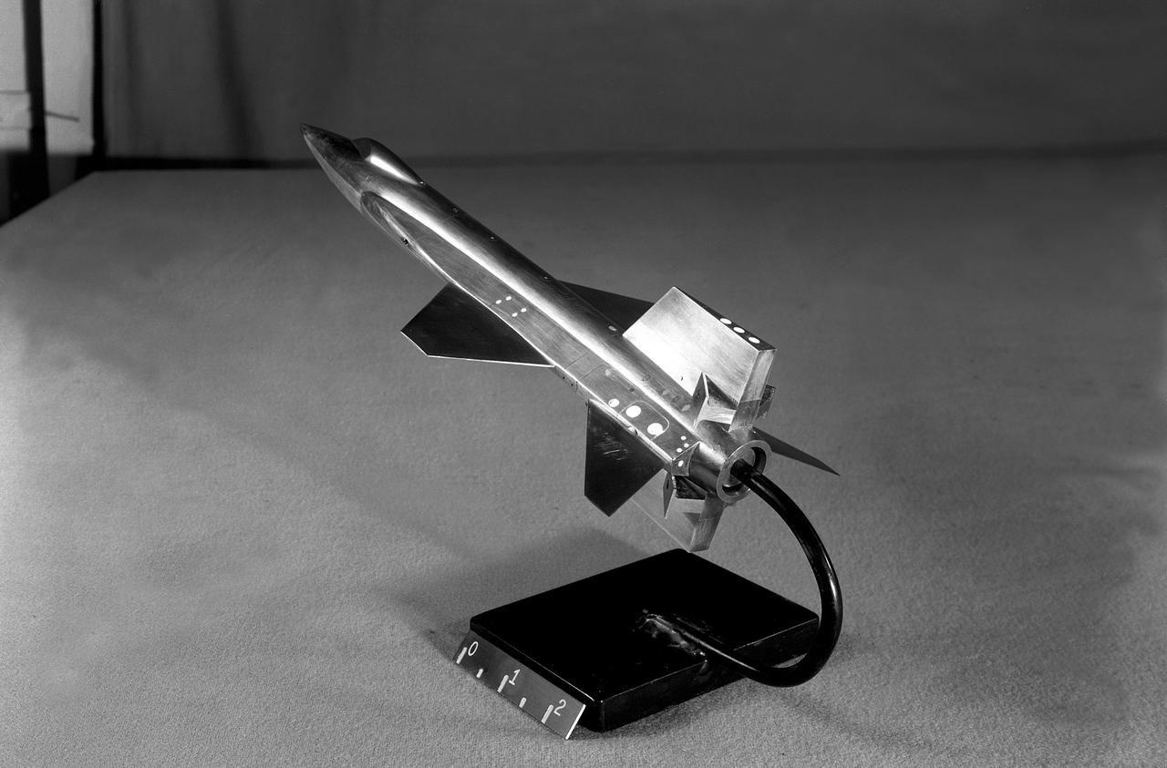
This scale-model of North American's initial X-15 design was tested in North American and NACA wind tunnels note the conventional tail and fuselage side-tunnels that extend far toward the aircraft nose. North American engineers would determine that the variable wedge-angle stabilizer created a weight issue, and aeronautical testing by Langley engineers confirmed that the side-tunnels made the design less stable.
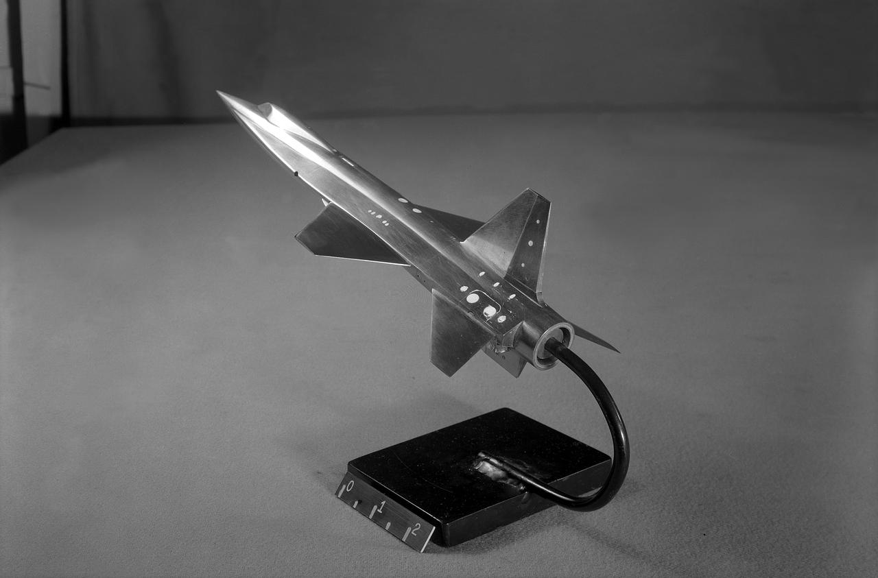
This scale-model of North American's initial X-15 design was tested in North American and NACA wind tunnels note the conventional tail and fuselage side-tunnels that extend far toward the aircraft nose. North American engineers would determine that the variable wedge-angle stabilizer created a weight issue, and aeronautical testing by Langley engineers confirmed that the side-tunnels made the design less stable.
John B. McKay was one of the first pilots assigned to the X-15 flight research program at NASA's Flight Research Center, Edwards, Calif. As a civilian research pilot and aeronautical engineer, he made 30 flights in X-15s from October 28, 1960, until September 8, 1966. His peak altitude was 295,600 feet, and his highest speed was 3863 mph (Mach 5.64). McKay was with the NACA and NASA from February 8,1951 until October 5, 1971 and specialized in high-speed flight research programs. He began as an NACA intern, but assumed pilot status on July 11, 1952. In addition to the X-l5, he flew such experimental aircraft as the D-558-1, D-558-2, X-lB, and the X-lE. He has also served as a research pilot on flight programs involving the F-100, F-102, F-104, and the F-107. Born on December 8, 1922, in Portsmouth, Va., McKay graduated from Virginia Polytechnic Institute in 195O with a Bachelor of Science degree in Aeronautical Engineering. During World War II he served as a Navy pilot in the Pacific Theater, earning the Air Medal and Two Clusters, and a Presidential Unit Citation. McKay wrote several technical papers, and was a member of the American Institute of Aeronautics and Astronautics, as well as the Society of Experimental Test Pilots. He passed away on April 27, 1975.
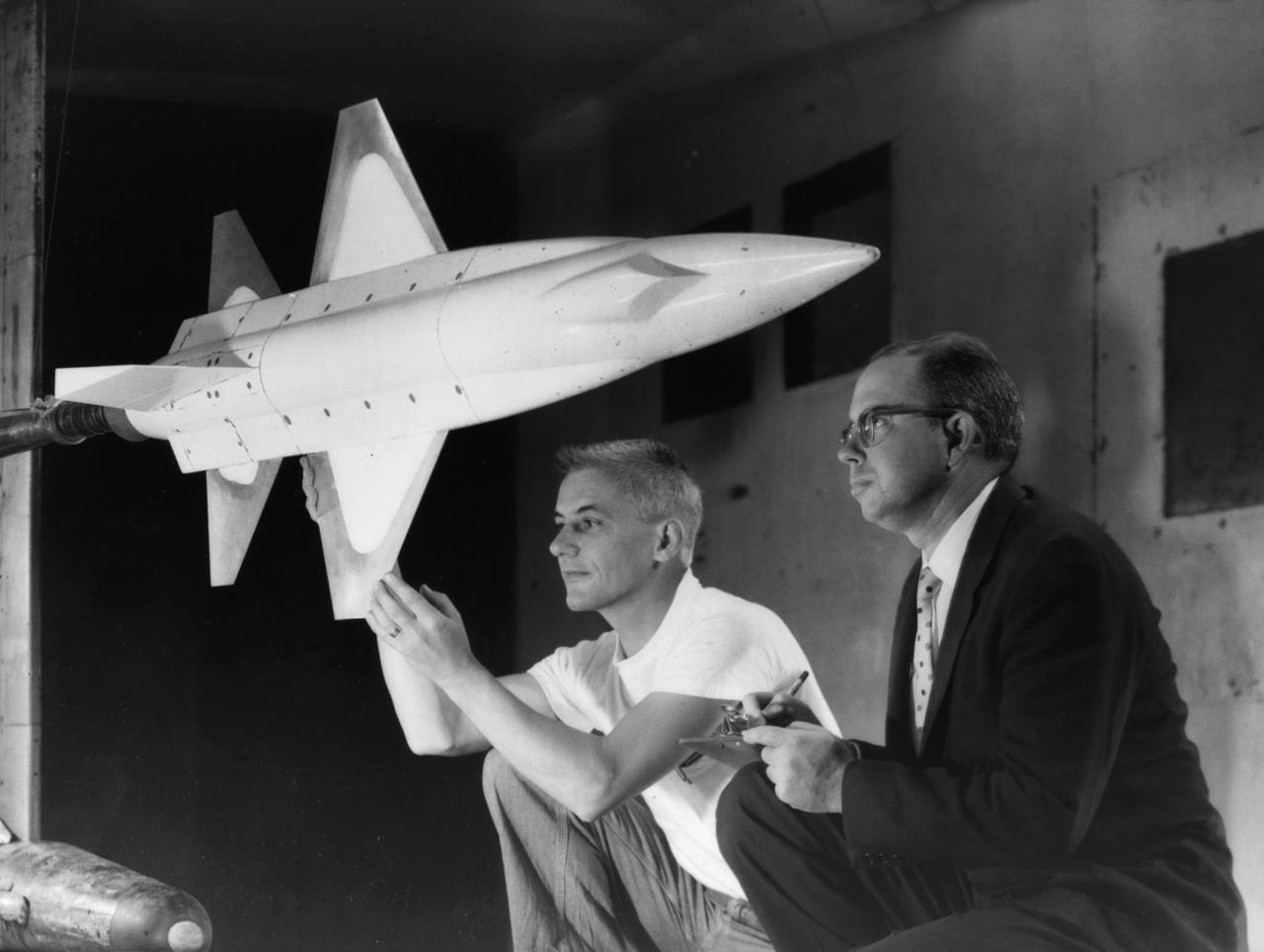
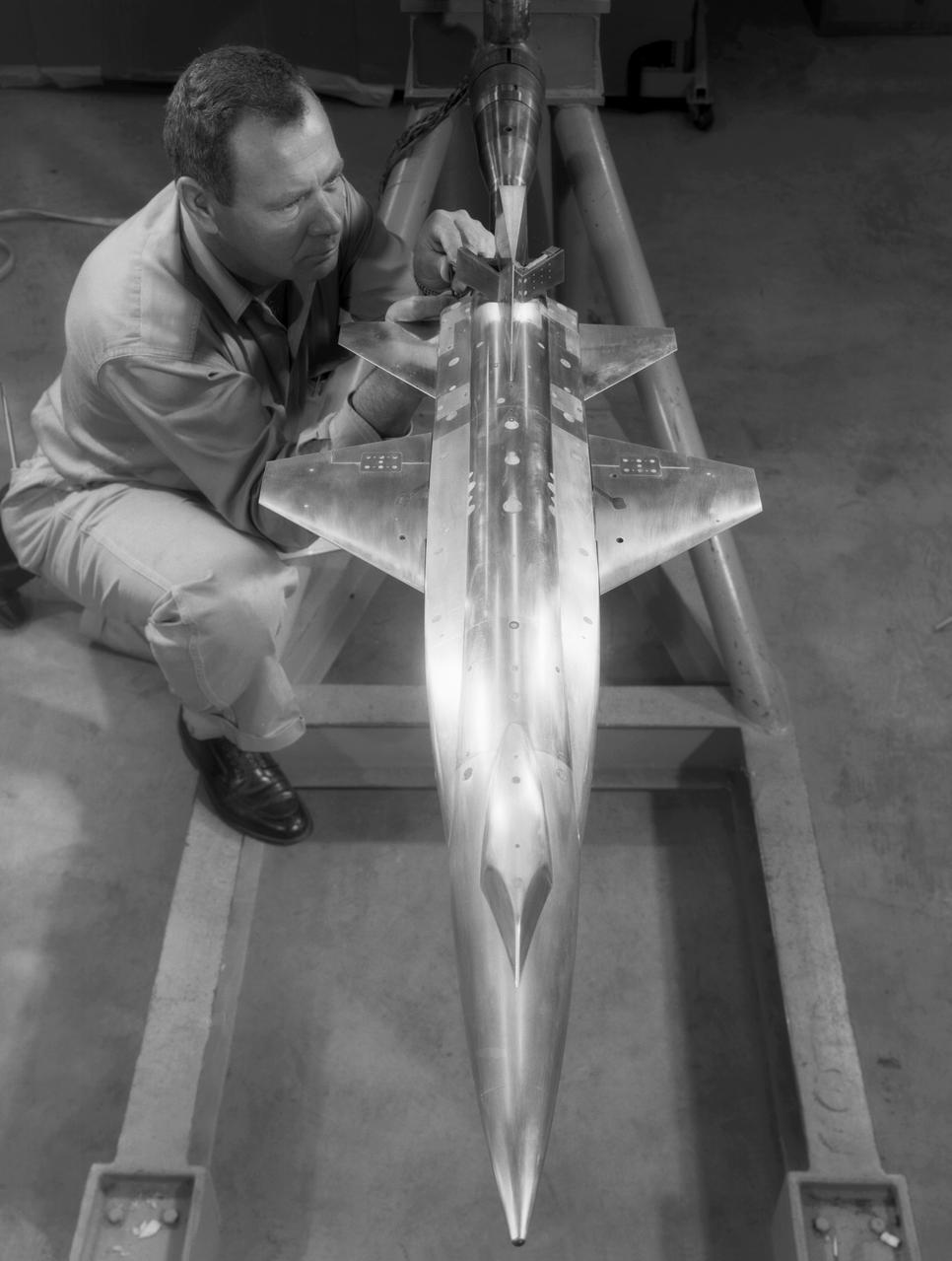
A 1/10th Scale Model of the X-15 research plane is prepared in Langley's 7 x 10 Foot Wind Tunnel for studies relating to spin characteristics. -- Photograph published in Winds of Change, 75th Anniversary NASA publication (page 66), by James Schultz.
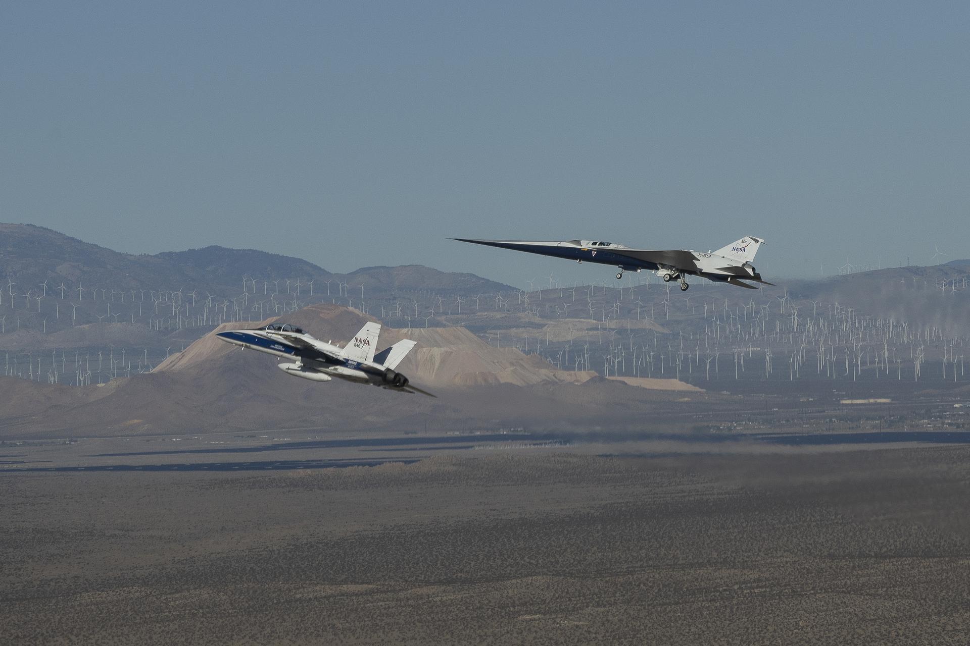
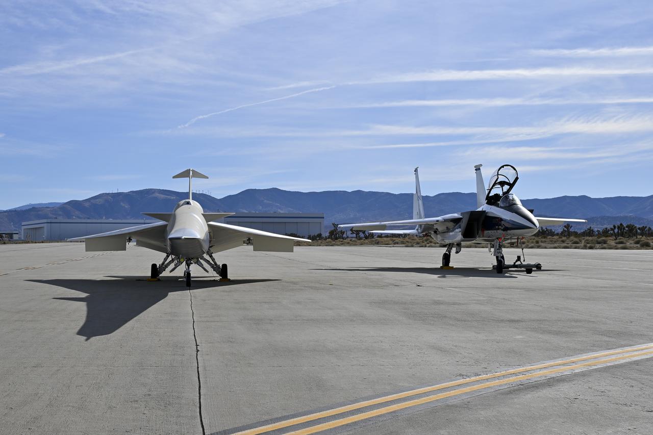
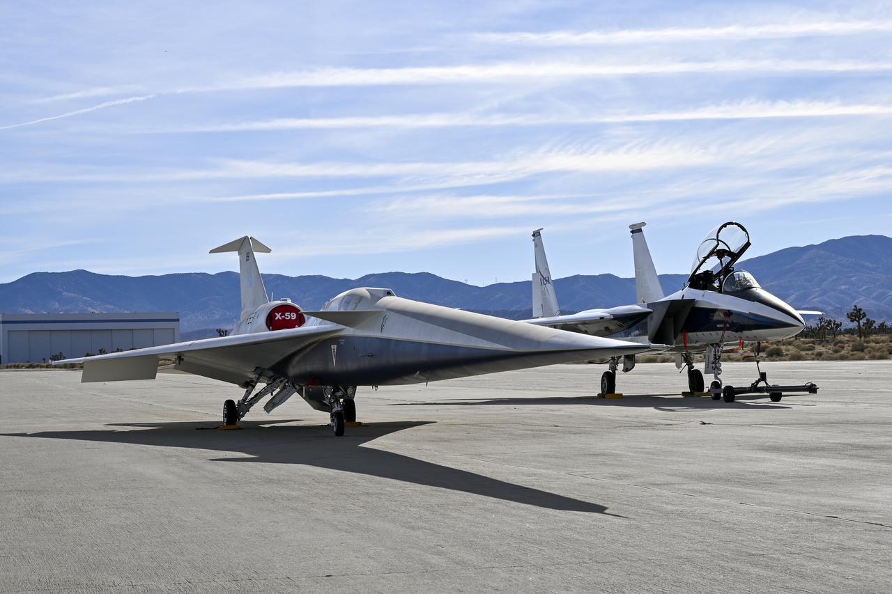
NASA’s X-59 quiet supersonic research aircraft flies above Palmdale and Edwards, California, on its first flight Tuesday, Oct. 28, 2025, accompanied by a NASA F-15 research aircraft. The F-15 monitored the X-59 during the flight as it traveled to NASA’s Armstrong Flight Research Center in Edwards, California, where it will begin flight testing for NASA’s Quesst mission, which aims to demonstrate quiet supersonic flight over land.
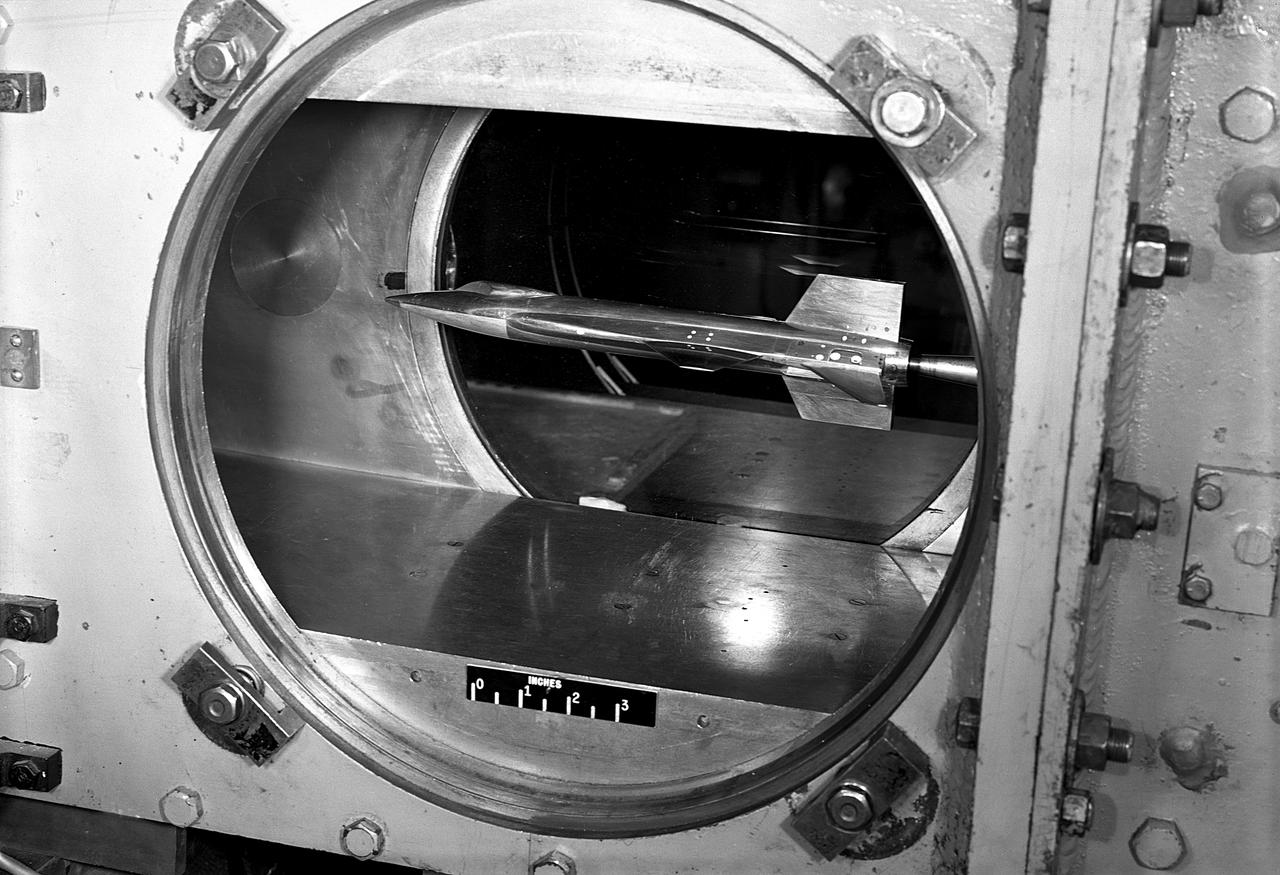
Scale-model of final X-15 configuration, mounted for testing in the Langley 11-Inch Hypersonic Tunnel.
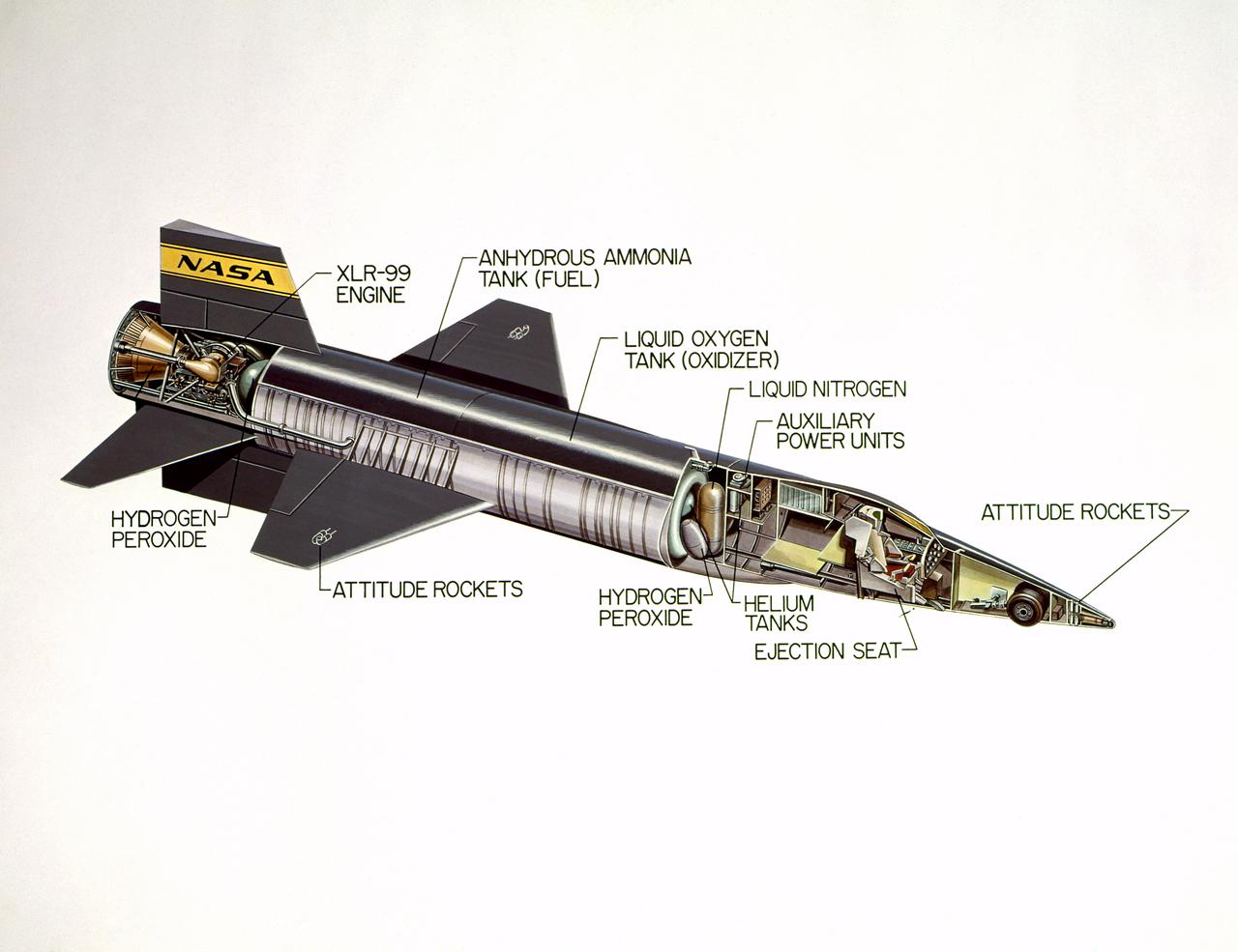
Cutaway drawing of the North American X-15.
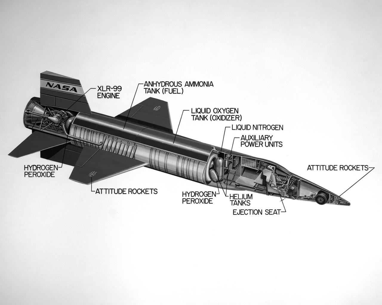
Cutaway drawing of the North American X-15.
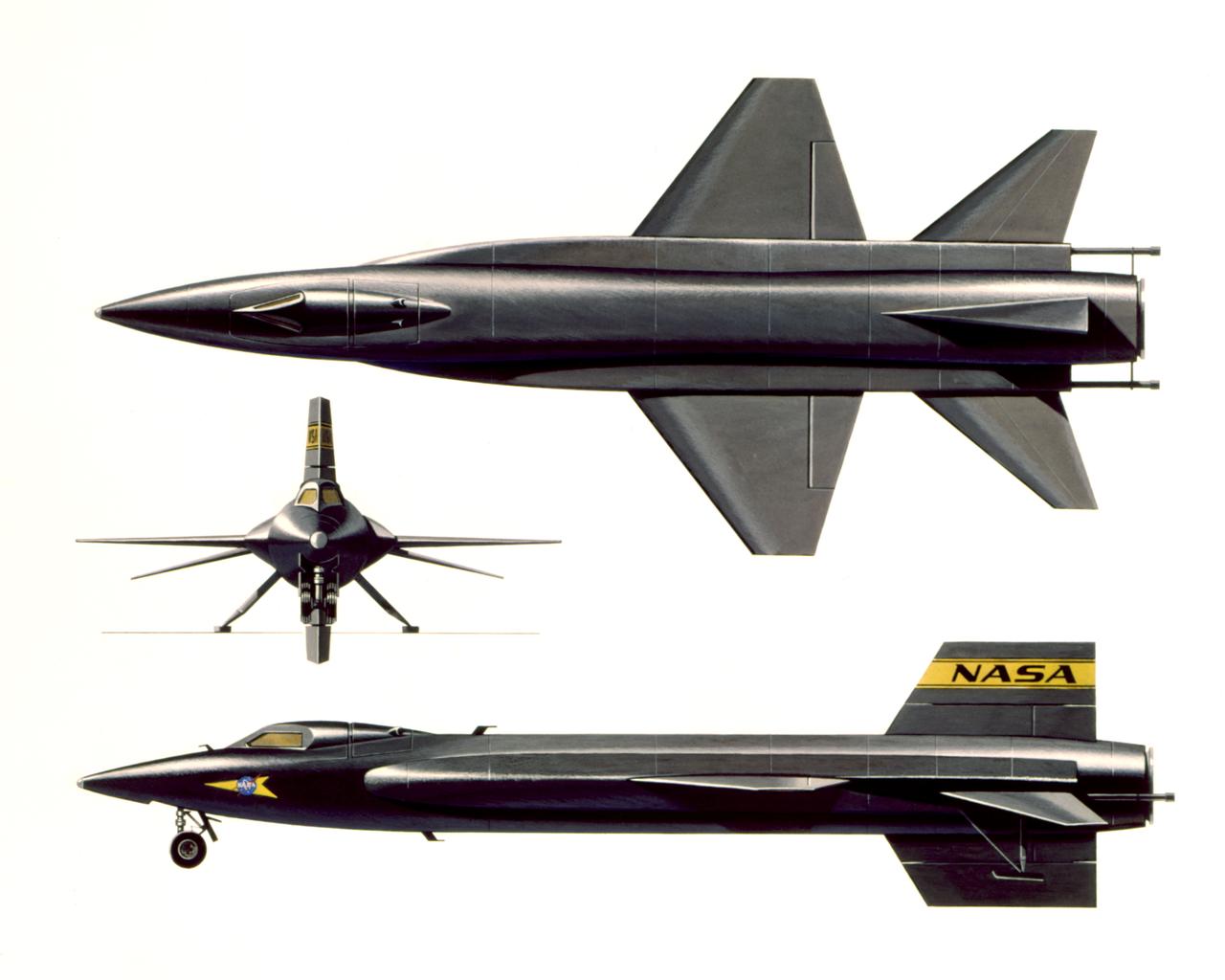
Three view art of the North American X-15.
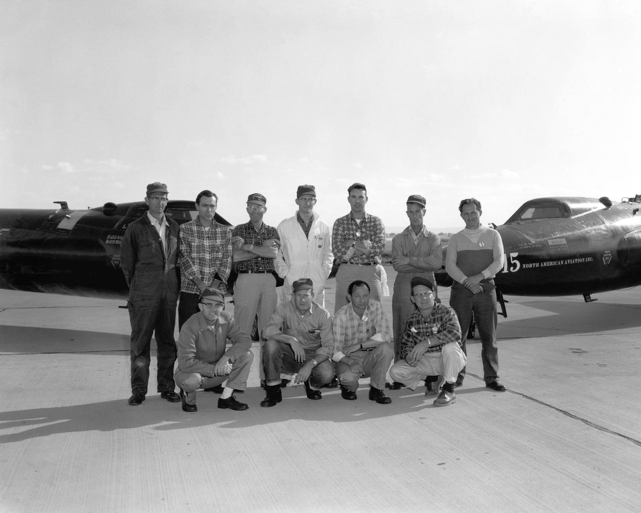
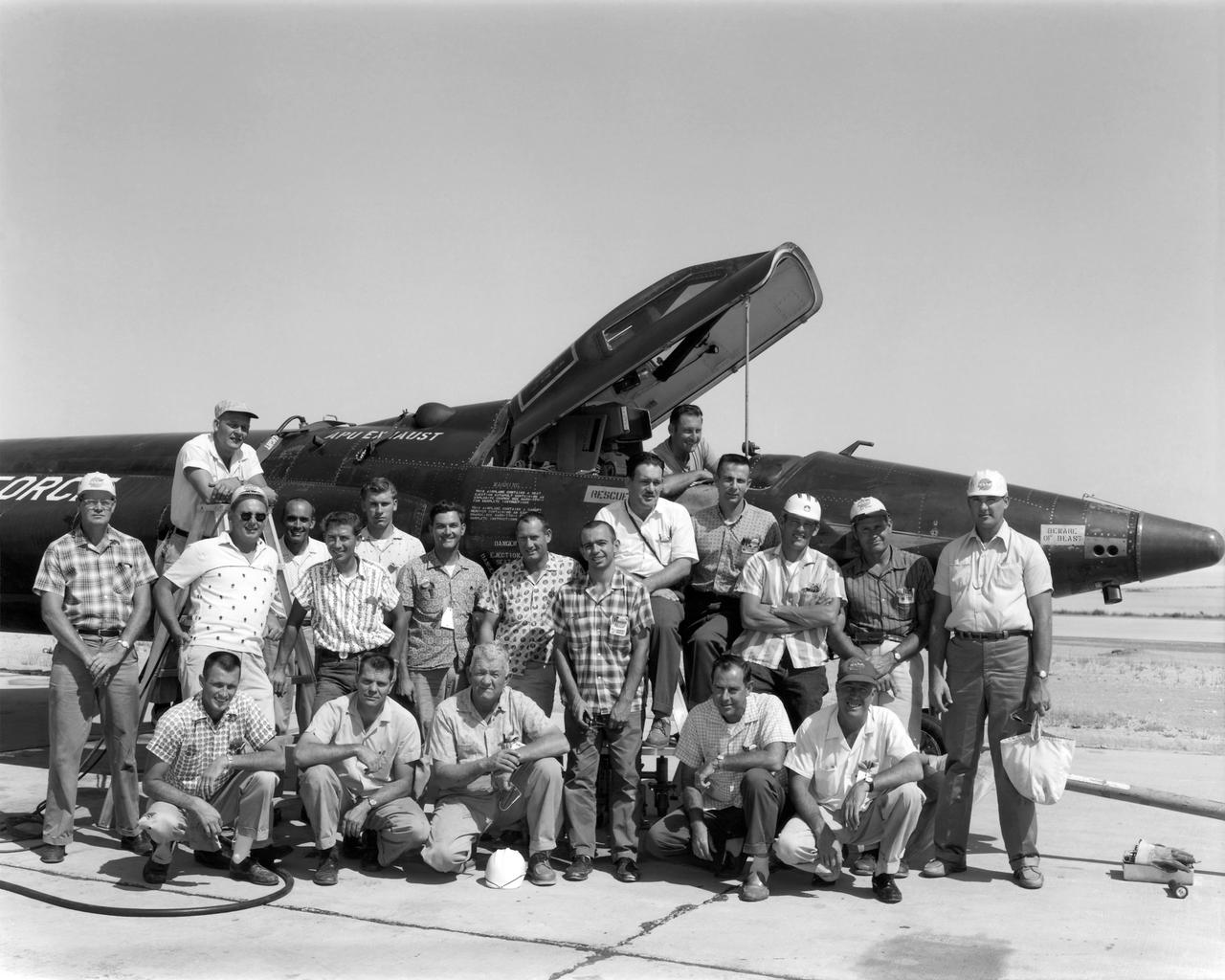
X-15 personnel. A photo commemorating all three X-15's being flown during the same week. Back Row, left to right: John "Bill" Lovett, John E. Huntington, Homer Hall, Robert E. "Bob" Allen, Lorenzo "Larry" Barnett, Charles "Charlie" Russell, Sylvester Weeks Kneeling, left to right: Gilbert "Gil" Kincaid, George E. Trott, Joseph "Joe" Huxman, Willard Glasscock

X-15 launch techniques were investigated using on-twentieth scale models mounted in the 7x10 FT Tunnel. -- Photograph published in Winds of Change, 75th Anniversary NASA publication (page 67), by James Schultz. -- Photograph also published in Sixty Years of Aeronautical Research 1917-1977 - a NASA publication (page 49), by David A. Anderton.
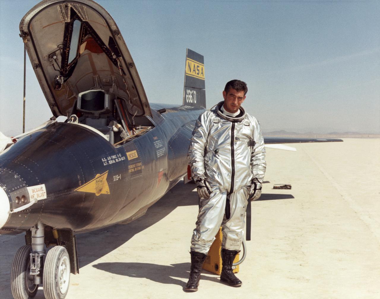
Air Force test pilot Maj. Michael J. Adams stands beside X-15 ship number one. Adams was selected for the X-15 program in 1966 and made his first flight on Oct. 6, 1966. On Nov. 15, 1967, Adams made his seventh and final X-15 flight. The X-15 launched from the B-52, but during the ascent an electrical problem affected the X-15's control system. The aircraft crashed northwest of Cuddeback Lake, California, causing the death of Adams. He was posthumously awarded Air Force astronaut wings because his final flight exceeded 50 miles in altitude. Adams was the only pilot lost in the 199-flight X-15 program.
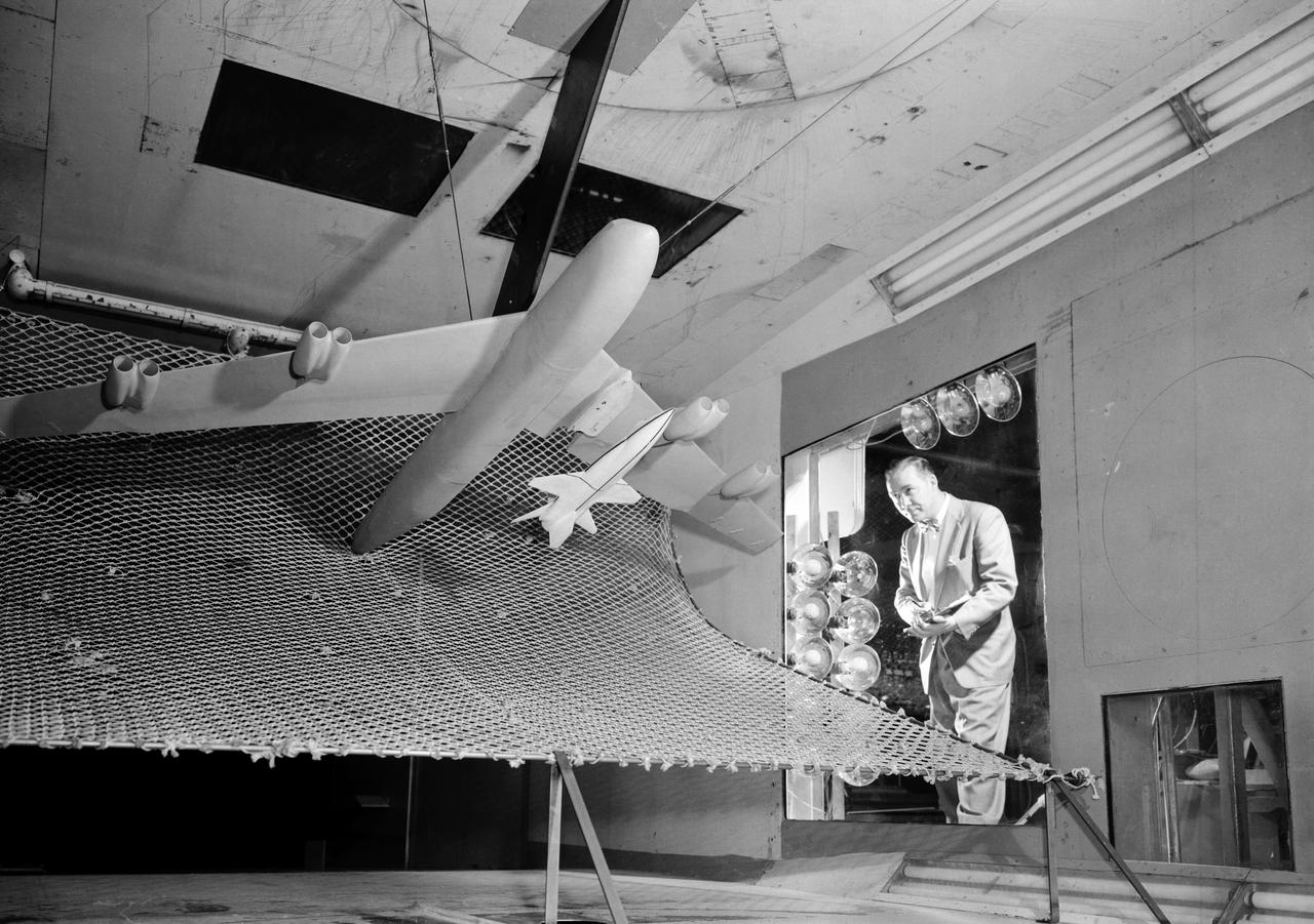
A one-twentieth scale model of the X-15 originally suspended beneath the wing of a B-52 is observed by a scientist of the National Aeronautics and Space Administration (NASA) as it leaves the bomber model in tests to determine the release characteristics and drop motion of the research airplane. Caption: The aerodynamics of air launching the North American X-15 being investigated in the 300MPH Low Speed 7x10 Tunnel, about 1957. Photograph published in Engineer in Charge: A History of the Langley Aeronautical Laboratory, 1917-1958 by James R. Hansen. Page 366. Photograph also published in Sixty Years of Aeronautical Research 1917-1977 By David A. Anderton. A NASA publication. Page 49.
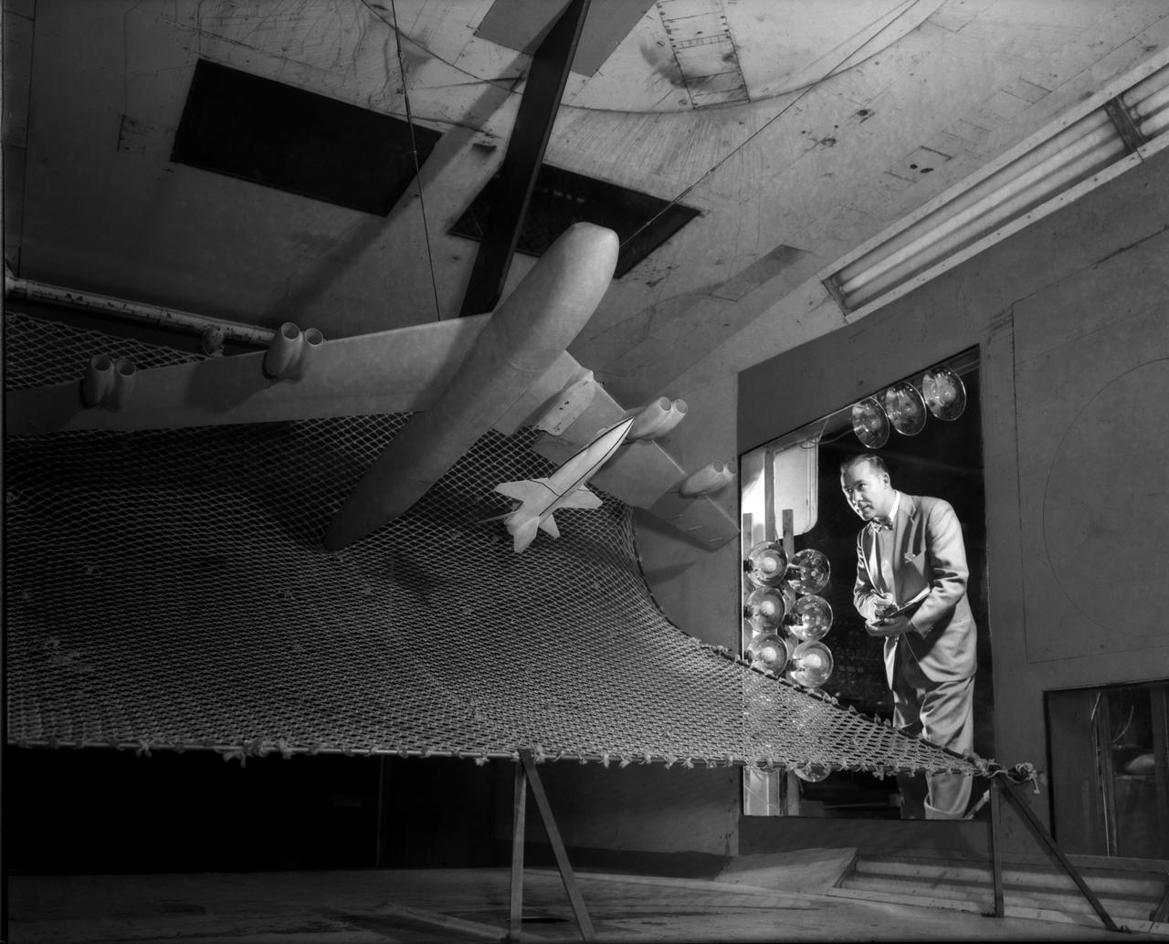
A one-twentieth scale model of the X-15 originally suspended beneath the wing of a B-52 is observed by a scientist of the National Aeronautics and Space Administration (NASA) as it leaves the bomber model in tests to determine the release characteristics and drop motion of the research airplane. Caption: The aerodynamics of air launching the North American X-15 being investigated in the 300MPH Low Speed 7x10 Tunnel, about 1957. Photograph published in Engineer in Charge: A History of the Langley Aeronautical Laboratory, 1917-1958 by James R. Hansen. Page 366. Photograph also published in Sixty Years of Aeronautical Research 1917-1977 By David A. Anderton. A NASA publication. Page 49.
X-15 personnel July 1962 Cockpit: Edward "Ed" Nice Ladder: Thomas "Tom" McAlister Back Row, left to right: William Clark, Edward "Ed" Sabo, Donald "Don" Hall, Billy Furr, Allen Dustin, Raymond "Ray" White, George E. Trott, Alfred "Al" Grieshaber, Merle Curtis, LeRoy "Lee" Adelsbach, Allen Lowe, Jay L. King, Lorenzo "Larry" Barnett. Kneeling, left to right: Byron Gibbs, Price "Bob" Workman, Ira Cupp, unidentified, John Gordon.
North American X-15 Drop Model
North American X-15 Drop Model
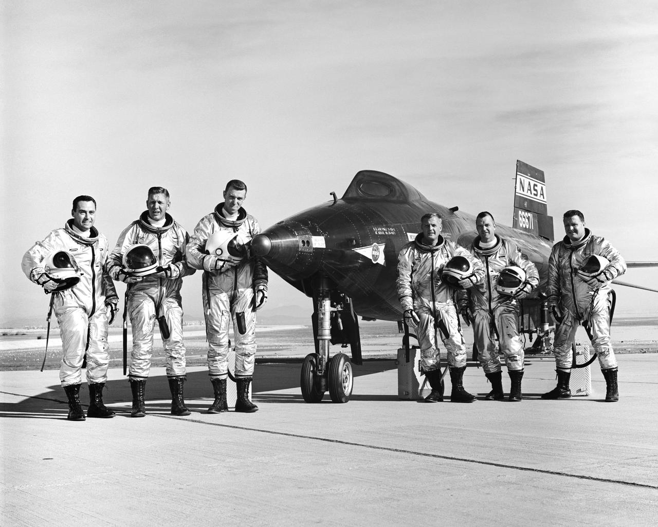
X-15 Pilots, Left to Right: Air Force pilot William J. "Pete" Knight, Air Force Major Robert A. Rushworth, Air Force Captain Joseph H. Engle, NASA pilot Milton O. Thompson, NASA pilot Bill Dana, and NASA pilot John B. "Jack" McKay.
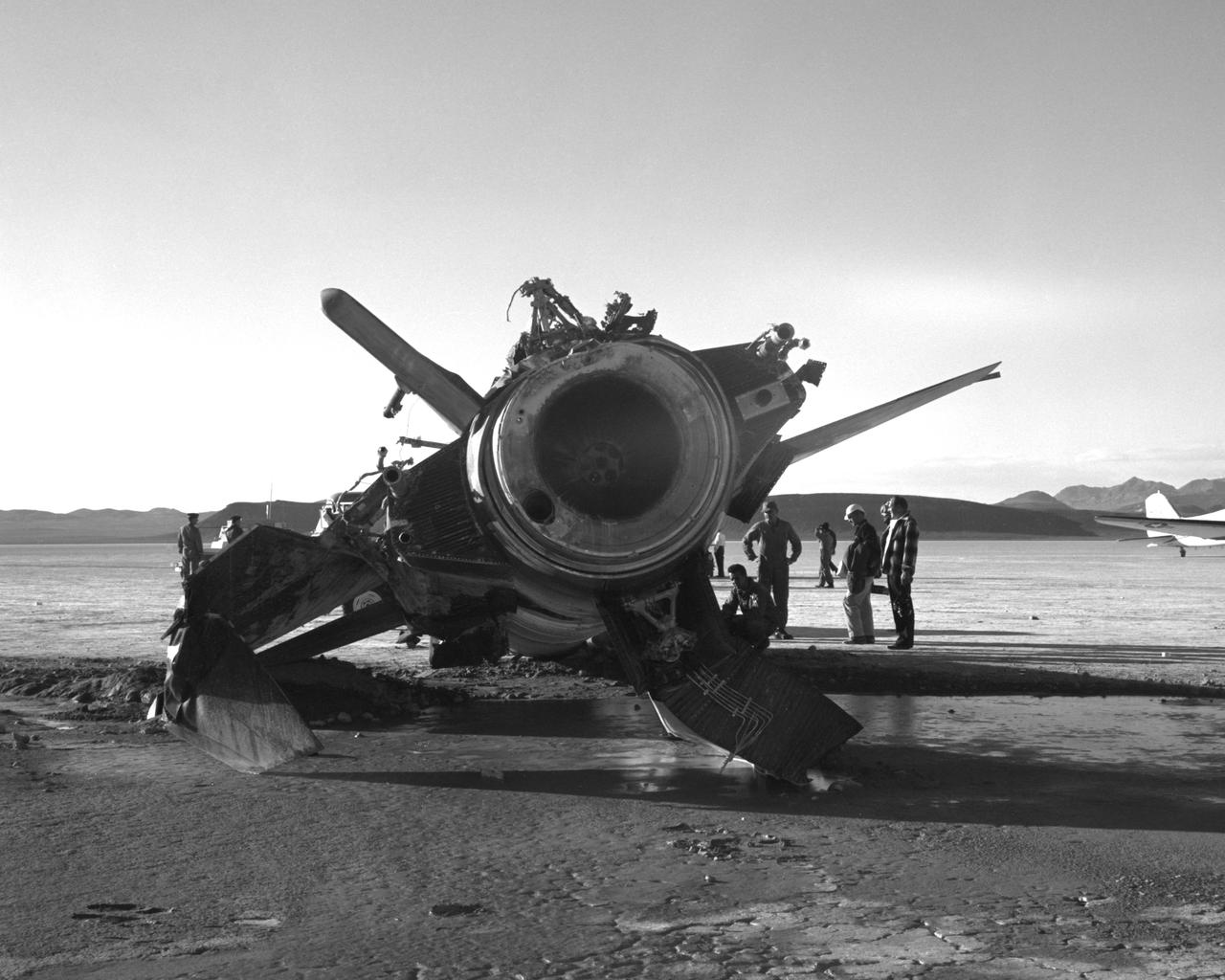
NASA research pilot Jack McKay was injured in a crash landing of the X-15 #2 on November 9, 1962. Following the launch from the B-52 to begin flight 2-31-52, he started the X-15's rocket engine, only to discover that it produced just 30 percent of its maximum thrust. He had to make a high-speed emergency landing on Mud Lake, NV, without flaps but with a significant amount of fuel still in the aircraft. As the X-15 slid across the lakebed, the left skid collapsed; the aircraft turned sideways and flipped onto its back. McKay suffered back injuries but was eventually able to resume X-15 pilot duties, making 22 more flights. The X-15 was sent back to North American Aviation and rebuilt into the X-15A-2.
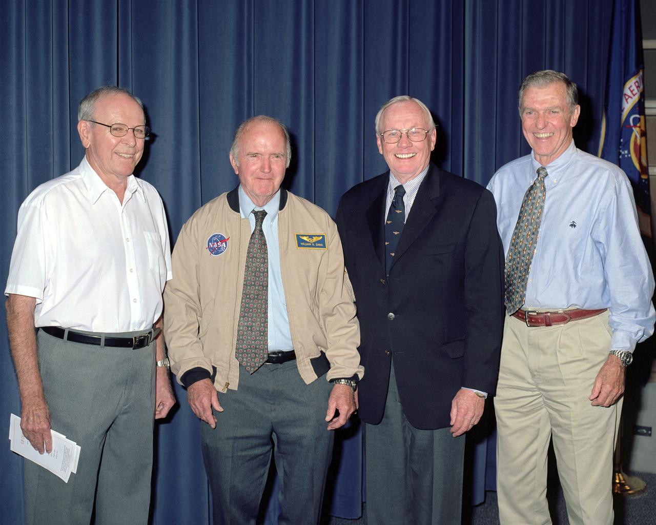
Four of the five surviving X-15 pilots were on hand when astronaut wings were presented to the three NASA pilots who flew the X-15 rocket plane into space in the 1960s, Bill Dana, Joe Walker (deceased) and Jack McKay (deceased). From left, Robert White, Dana, Neil Armstrong, Joe Engle.
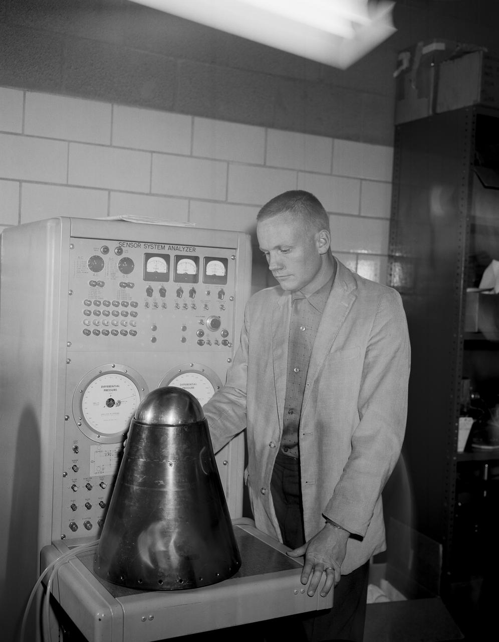
From the program’s inception, Neil Armstrong was actively engaged in both the piloting and engineering aspects of the X-15. He flew the first mission using a new flow-direction sensor (ball nose) and the first flight with a self-adaptive flight control system. Collaborating closely with designers and engineers on the system’s development, he made seven flights in the X-15 between December 1960 and July 1962. During these missions, he reached a peak altitude of 207,500 feet in the X-15-3 and a top speed of 3,989 mph (Mach 5.74) in the X-15-1.
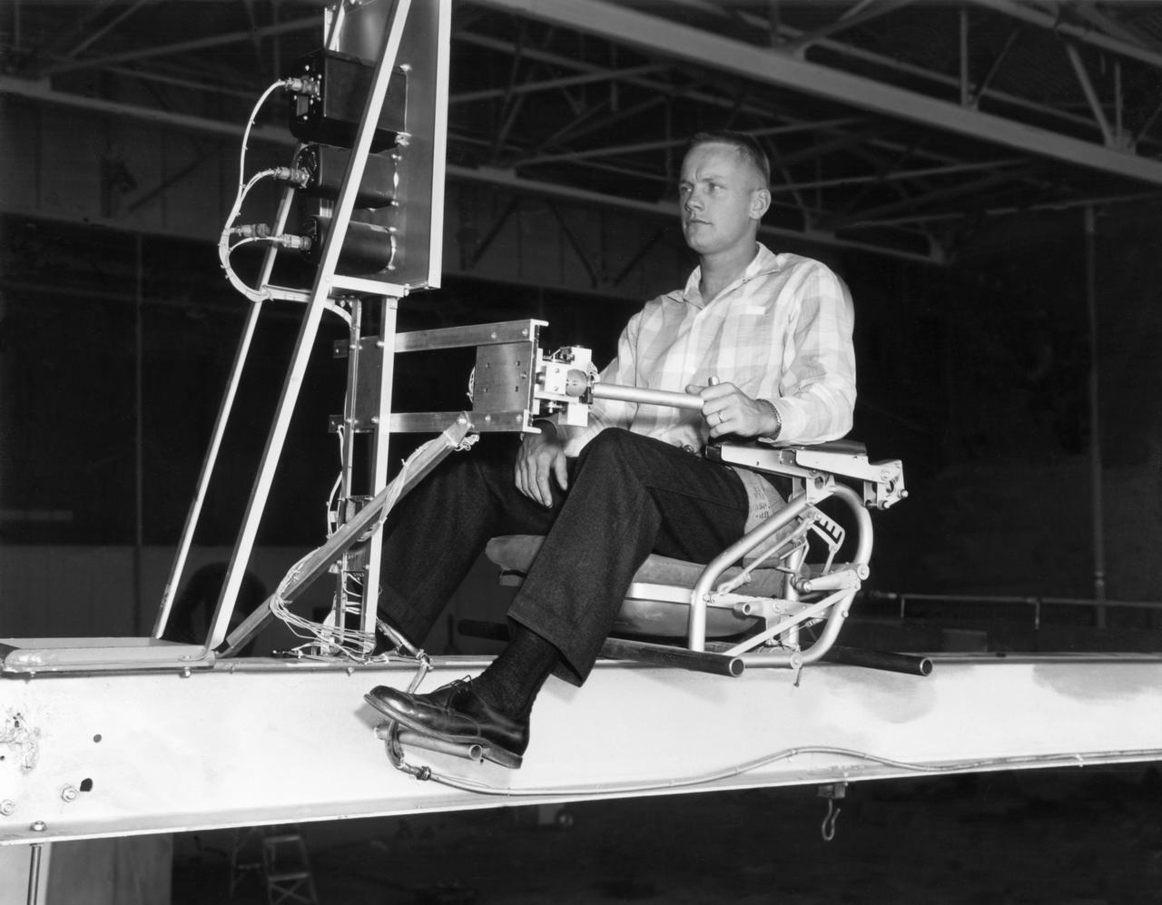
Famed astronaut Neil A. Armstrong, the first man to set foot on the moon during the historic Apollo 11 space mission in July 1969, served for seven years as a research pilot at the NACA-NASA High-Speed Flight Station, now the Dryden Flight Research Center, at Edwards, California, before he entered the space program. Armstrong joined the National Advisory Committee for Aeronautics (NACA) at the Lewis Flight Propulsion Laboratory (later NASA's Lewis Research Center, Cleveland, Ohio, and today the Glenn Research Center) in 1955. Later that year, he transferred to the High-Speed Flight Station at Edwards as an aeronautical research scientist and then as a pilot, a position he held until becoming an astronaut in 1962. He was one of nine NASA astronauts in the second class to be chosen. As a research pilot Armstrong served as project pilot on the F-100A and F-100C aircraft, F-101, and the F-104A. He also flew the X-1B, X-5, F-105, F-106, B-47, KC-135, and Paresev. He left Dryden with a total of over 2450 flying hours. He was a member of the USAF-NASA Dyna-Soar Pilot Consultant Group before the Dyna-Soar project was cancelled, and studied X-20 Dyna-Soar approaches and abort maneuvers through use of the F-102A and F5D jet aircraft. Armstrong was actively engaged in both piloting and engineering aspects of the X-15 program from its inception. He completed the first flight in the aircraft equipped with a new flow-direction sensor (ball nose) and the initial flight in an X-15 equipped with a self-adaptive flight control system. He worked closely with designers and engineers in development of the adaptive system, and made seven flights in the rocket plane from December 1960 until July 1962. During those fights he reached a peak altitude of 207,500 feet in the X-15-3, and a speed of 3,989 mph (Mach 5.74) in the X-15-1. Armstrong has a total of 8 days and 14 hours in space, including 2 hours and 48 minutes walking on the Moon. In March 1966 he was commander of the Gemini 8 or
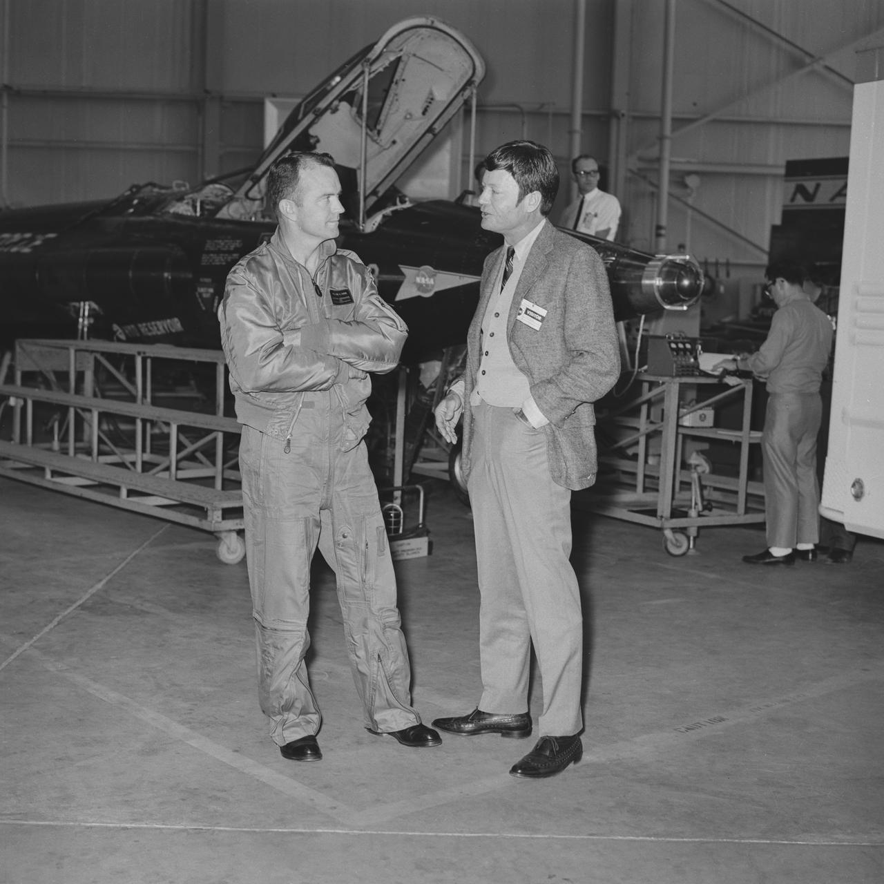
The 1960s Star Trek television series’ cast member Chief Medical Officer Leonard ‘Bones’ McCoy played by DeForest Kelley talks to Bill Dana, NASA X-15 pilot, in front of one of three X-15’s during visit to NASA Dryden Flight Research Center, now Armstrong, back in 1967.
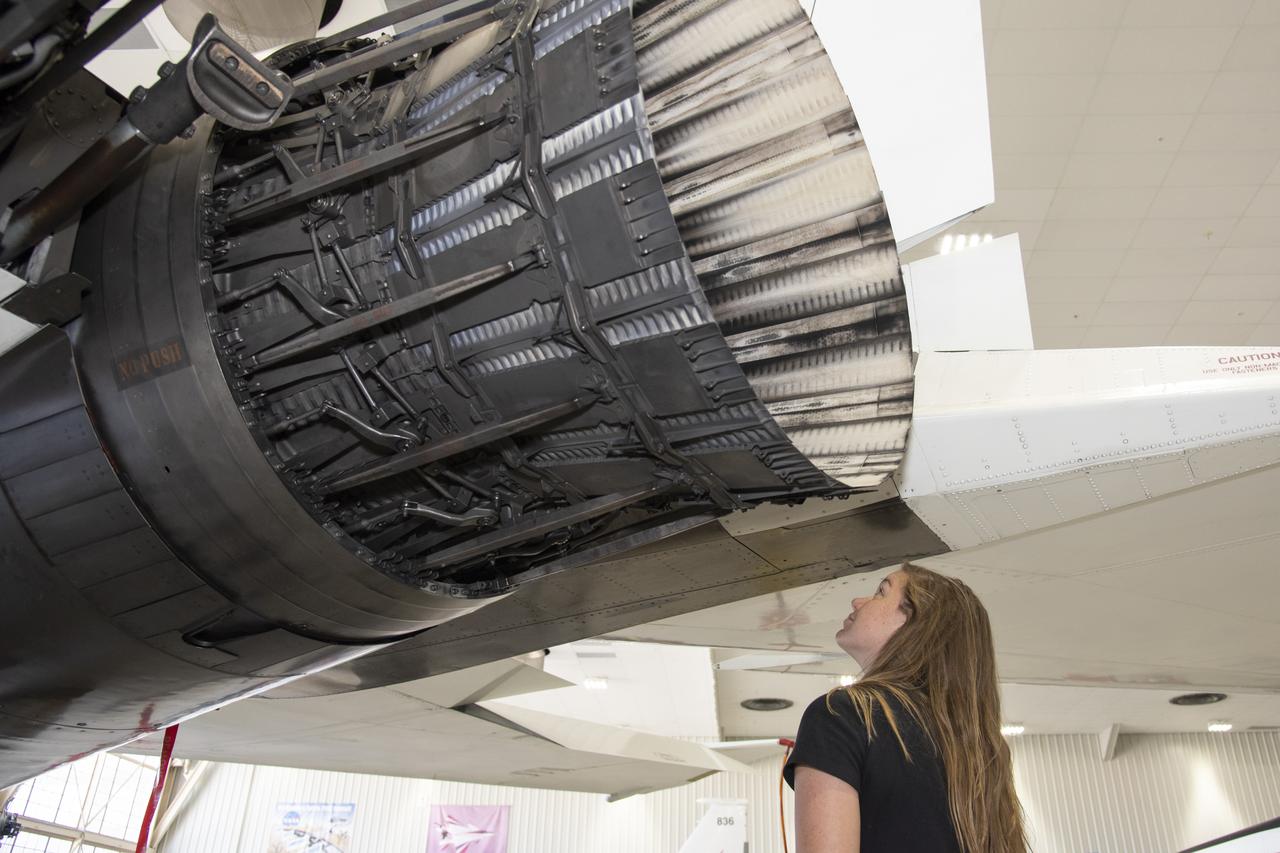
NASA’s 2017 astronaut candidates toured aircraft hangar at Armstrong Flight Research Center, in Southern California where Jenni Sidey-Gibbons looks inside engine nozzle of F-15 jet. The F-15 will fly in tandem with the X-59 QueSST during early flight test stages for the X-59 development.
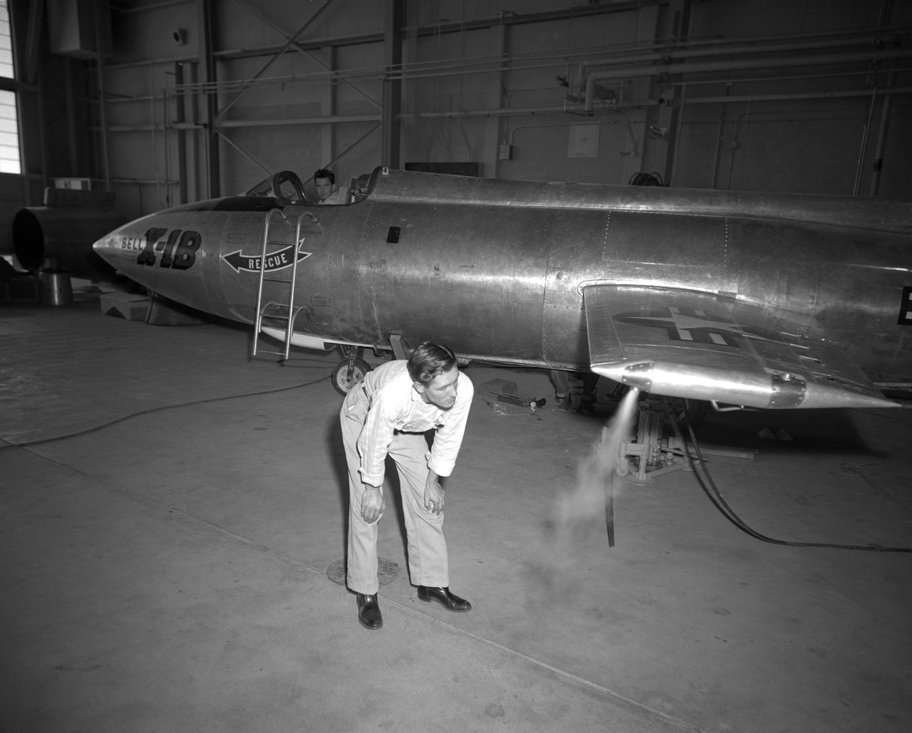
The X-1B reaction control system thrusters are tested in 1958 and later proven on the X-15 as a way to control a vehicle in the absence of dynamic pressure.
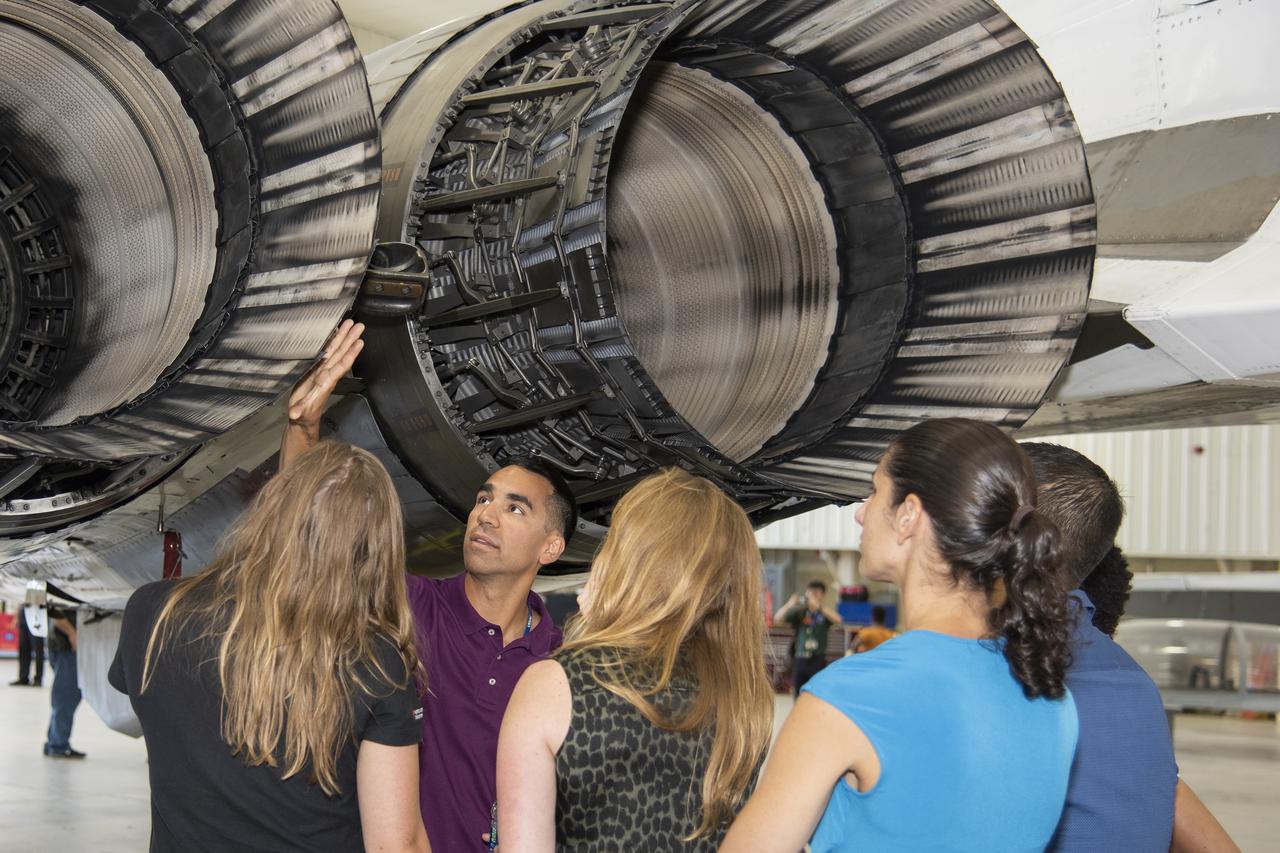
NASA's 2017 astronaut candidates toured aircraft hangar at Armstrong Flight Research Center, in Southern California (L to R) Jenni Sidey-Gibbons, Raja Chari, Loral O'Hara, Jasmin Moghbeli, Jonny Kim and Jessica Watkins look inside the engine nozzle of an F-15 jet. The F-15 will fly in tandem with the X-59 QueSST during early flight test stages for the X-59 development.
North American X-15 Model being readied for tests in Langley Unitary Plan
A NASA F-15 aircraft sits 20 feet off the left side of the X-59 aircraft, with a white hangar and hills in the background, during electromagnetic interference testing.
A NASA F-15 aircraft sits 20 feet off the left side of the X-59 aircraft, with a white hangar and hills in the background, during electromagnetic interference testing.

Southwestern US, with Las Vegas, NV in foreground, taken by X-15 Hycon HR-236 Camera during flt. 2-39-70 on June 27, 1965.
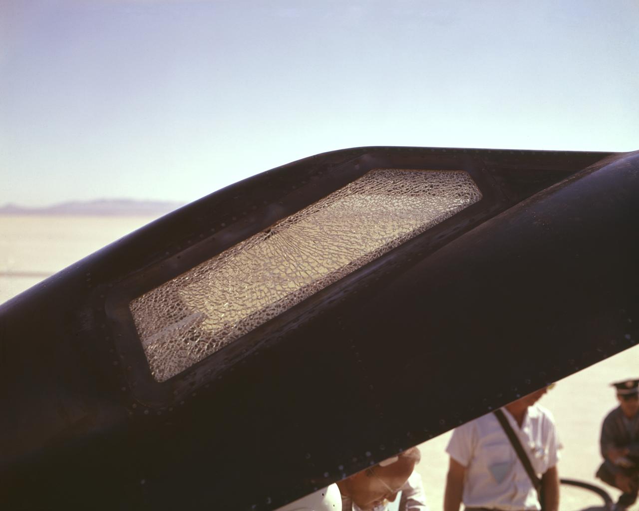
Cracked canopy glass on right side of X-15 #2 after flt. 2-21-37 on Nov. 9 1961. Robert White-pilot. First flight to mach 6.
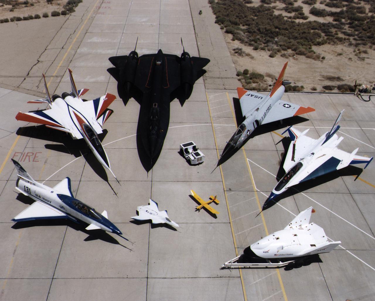
A collection of NASA's research aircraft on the ramp at the Dryden Flight Research Center in July 1997: X-31, F-15 ACTIVE, SR-71, F-106, F-16XL Ship #2, X-38, Radio Controlled Mothership and X-36.
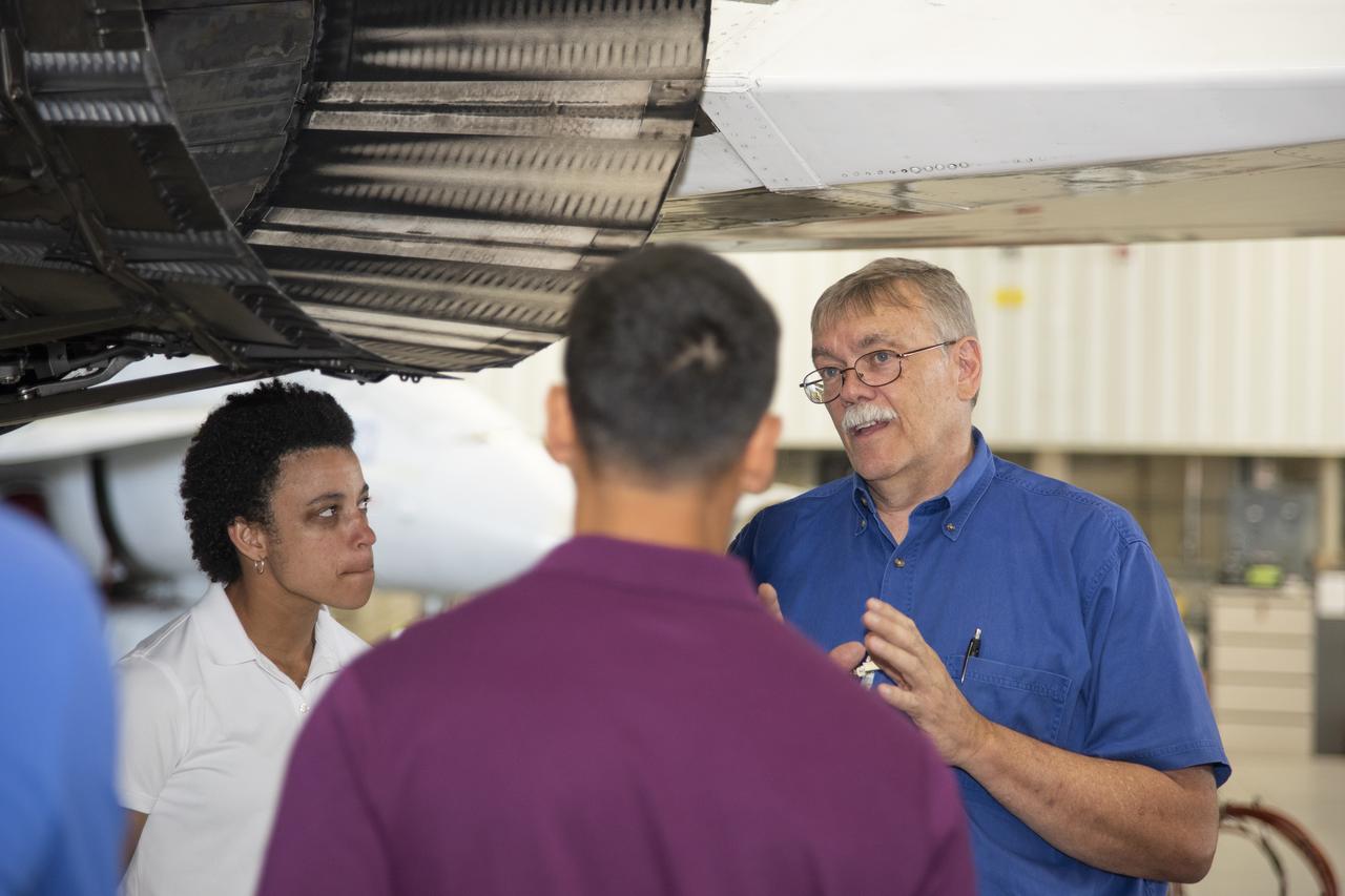
NASA's 2017 astronaut candidates toured aircraft hangar at Armstrong Flight Research Center, in Southern California where Crew Chief Tom Grindle talks with (L to R) Jessica Watkins and Raja Chari near engine nozzle of F-15 jet. The F-15 will fly in tandem with the X-59 QueSST during early flight test stages for the X-59 development.
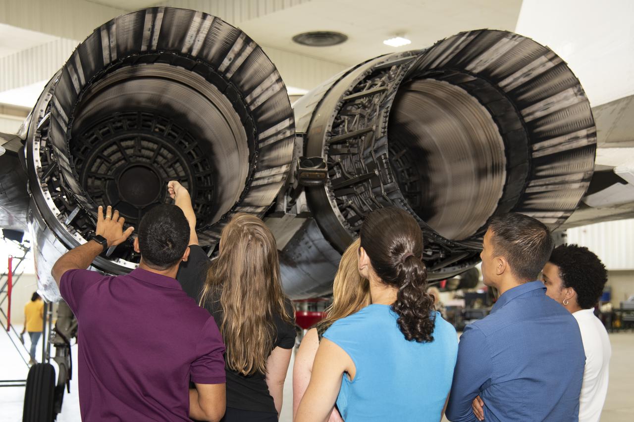
NASA's 2017 astronaut candidates toured aircraft hangar at Armstrong Flight Research Center, in Southern California (L to R) Raja Chari, Jenni Sidey-Gibbons, Loral O'Hara, Jasmin Moghbeli, Jonny Kim and Jessica Watkins look inside the engine nozzle of an F-15 jet. The F-15 will fly in tandem with the X-59 QueSST during early flight test stages for the X-59 development.
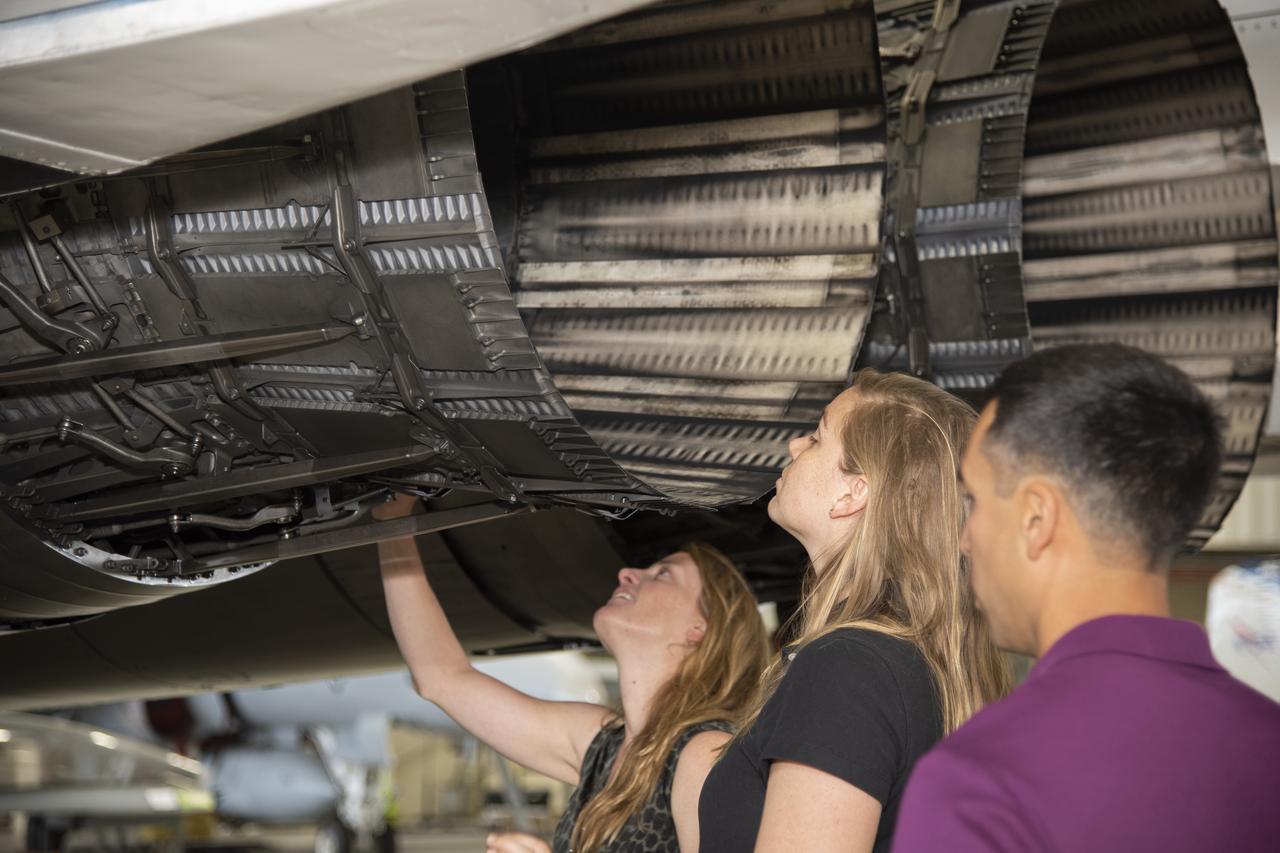
NASA's 2017 astronaut candidates toured aircraft hangar at Armstrong Flight Research Center, in Southern California where (L to R) Loral O'Hara, Jenni Sidey-Gibbons and Raja Chari look inside the engine nozzle of an F-15 jet. The F-15 will fly in tandem with the X-59 QueSST during early flight test stages for the X-59 development.
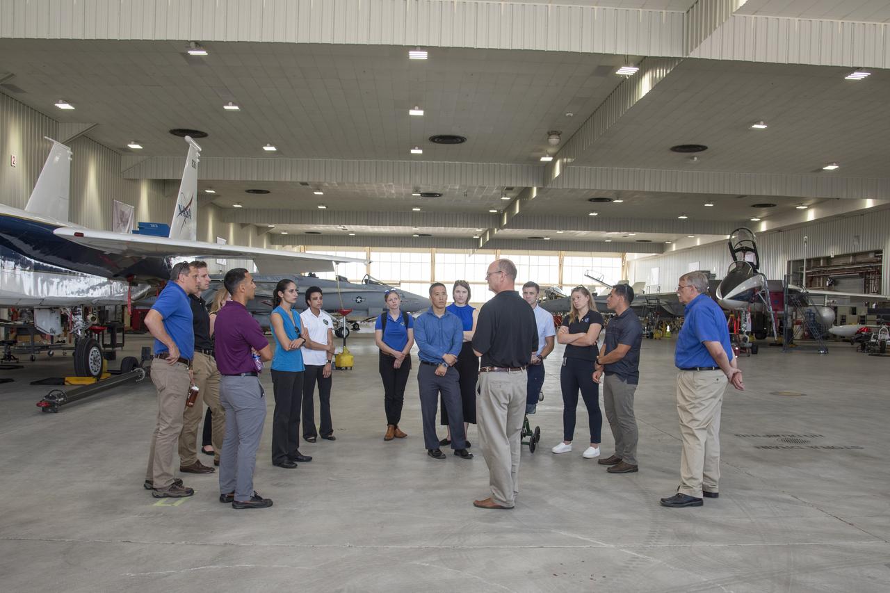
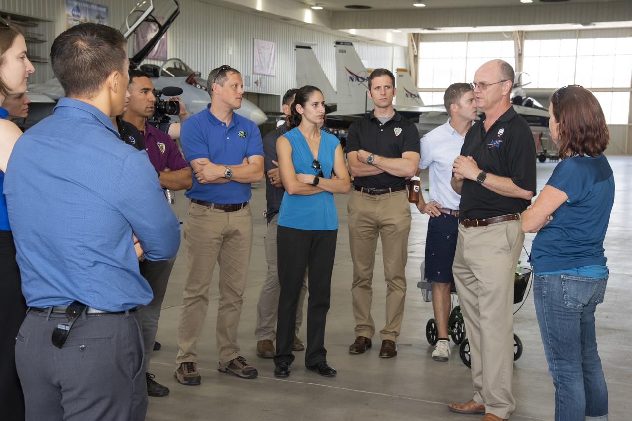
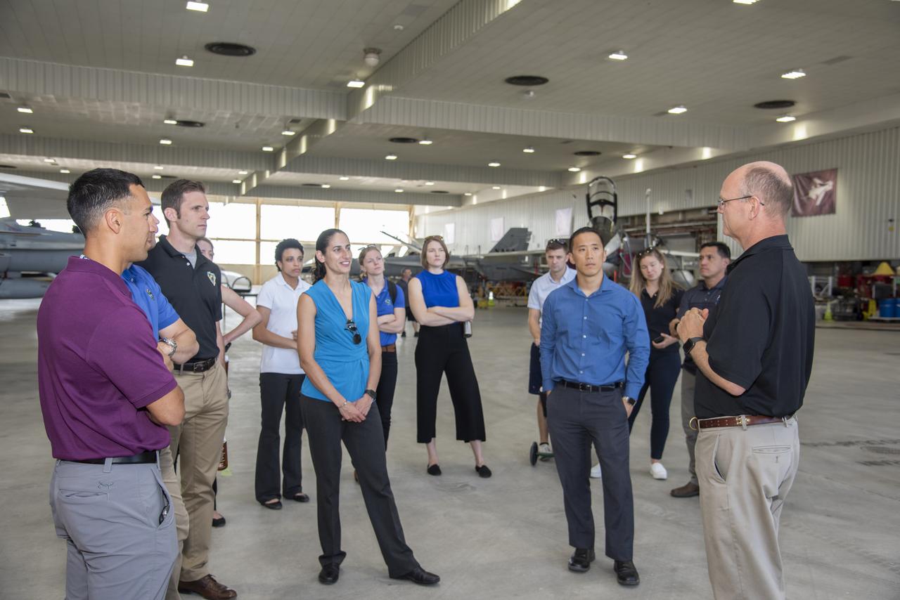
NASA's 2017 astronaut candidates toured aircraft hangar at Armstrong Flight Research Center, in Southern California. On the right, NASA's, X-59 pilot Nils Larsen, briefs the astronauts as they look at Armstrong's fleet of supersonic research support aircraft, including the F-15, which will fly in tandem with the X-59 QueSST during early flight test stages, and the F-18, which is conducting supersonic research in support of the overall mission.
NASA’s 2017 astronaut candidates toured aircraft hangar at Armstrong Flight Research Center, in Southern California. On the right, NASA’s, X-59 pilot Nils Larsen, briefs the astronauts as they look at Armstrong’s fleet of supersonic research support aircraft, including the F-15, which will fly in tandem with the X-59 QueSST during early flight test stages, and the F-18, which is conducting supersonic research in support of the overall mission.
NASA's 2017 astronaut candidates toured aircraft hangar at Armstrong Flight Research Center, in Southern California. On the right, NASA's, X-59 pilot Nils Larsen, briefs the astronauts as they look at Armstrong's fleet of supersonic research support aircraft, including the F-15, which will fly in tandem with the X-59 QueSST during early flight test stages, and the F-18, which is conducting supersonic research in support of the overall mission.
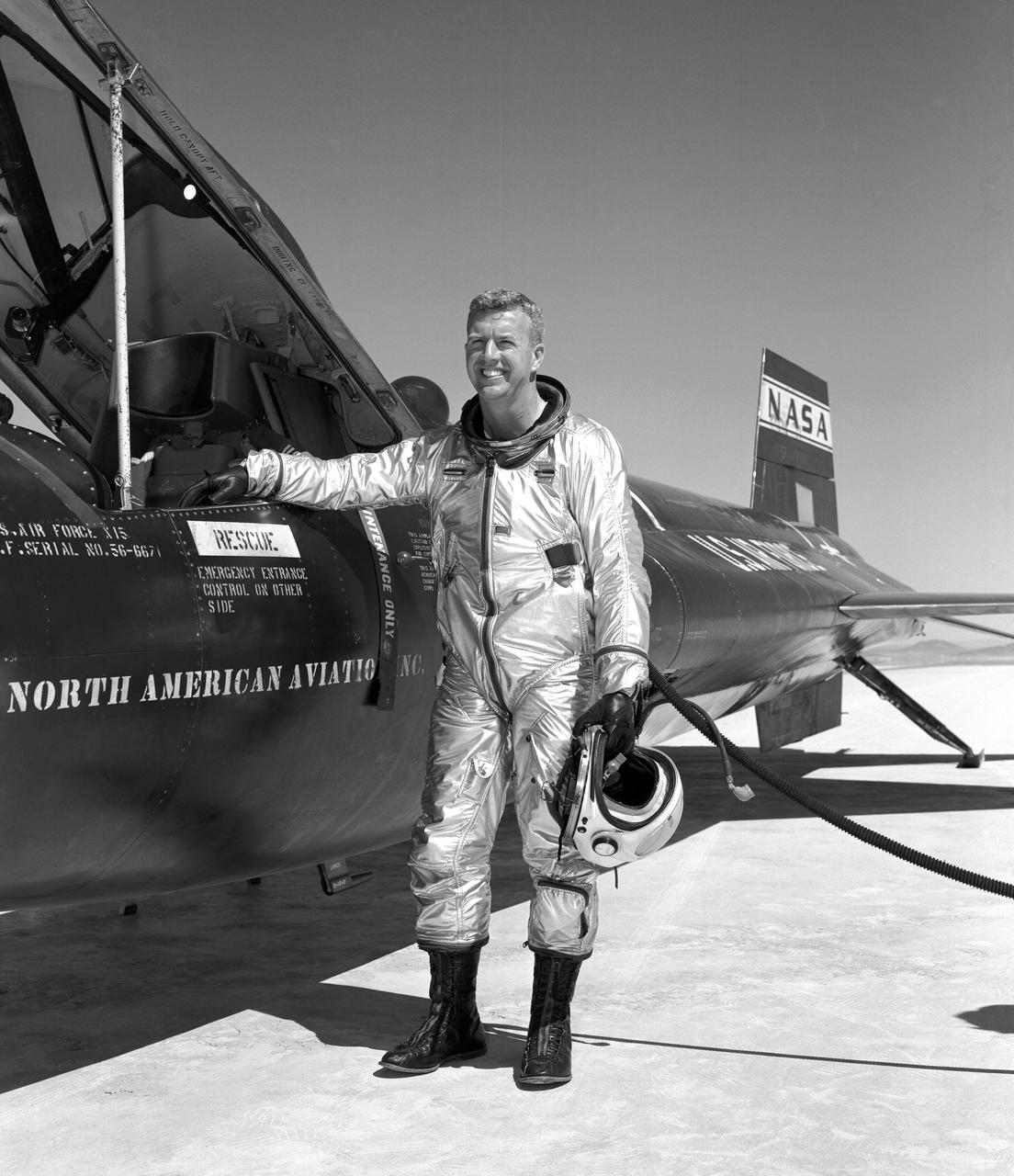
Walker made the first NASA-piloted X-15 flight March 25, 1960, and flew the aircraft 24 times, achieving its highest altitude (354,300 ft.) Aug. 22, 1963. He died piloting a F-104 that was caught up in a vortex of the XB-70.
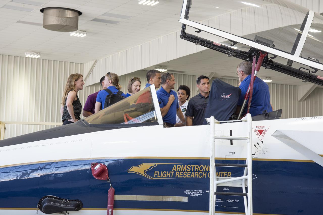
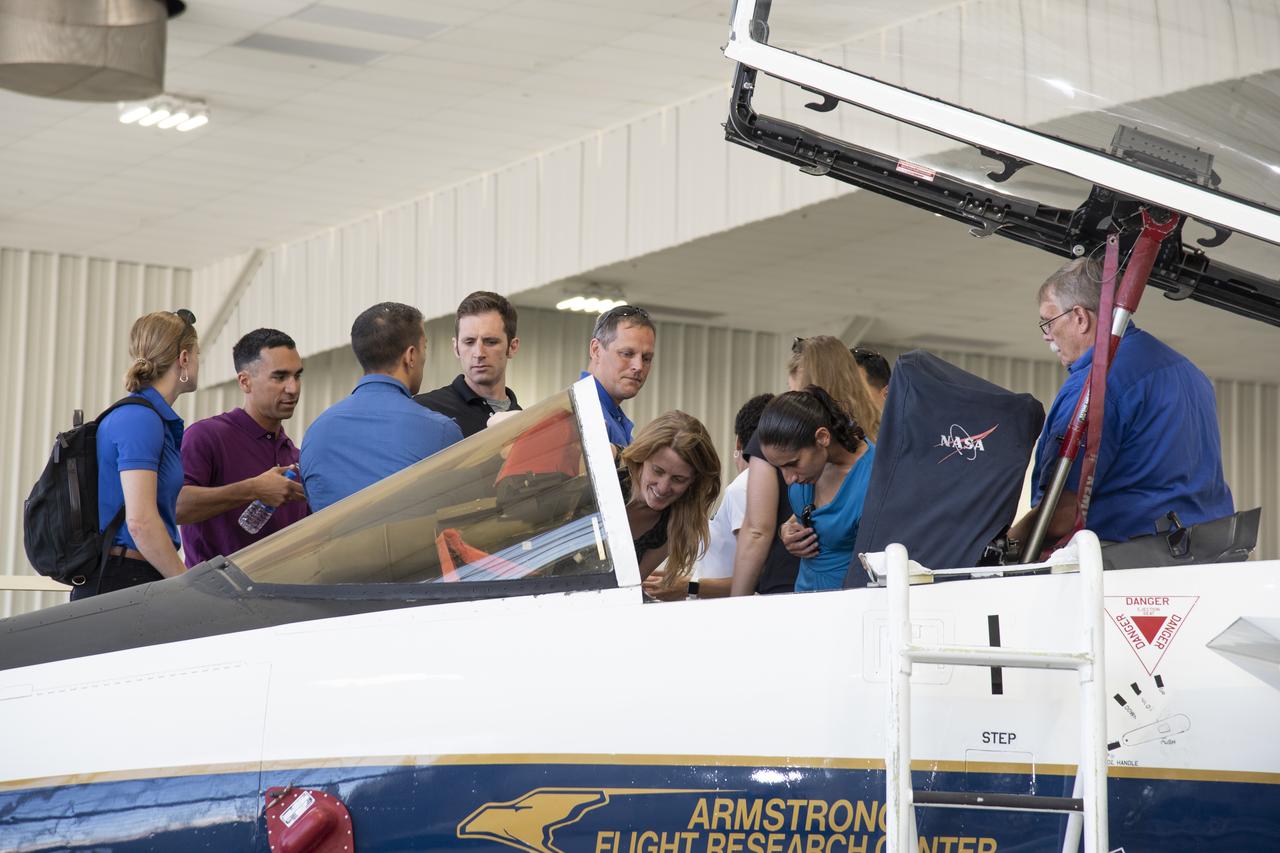
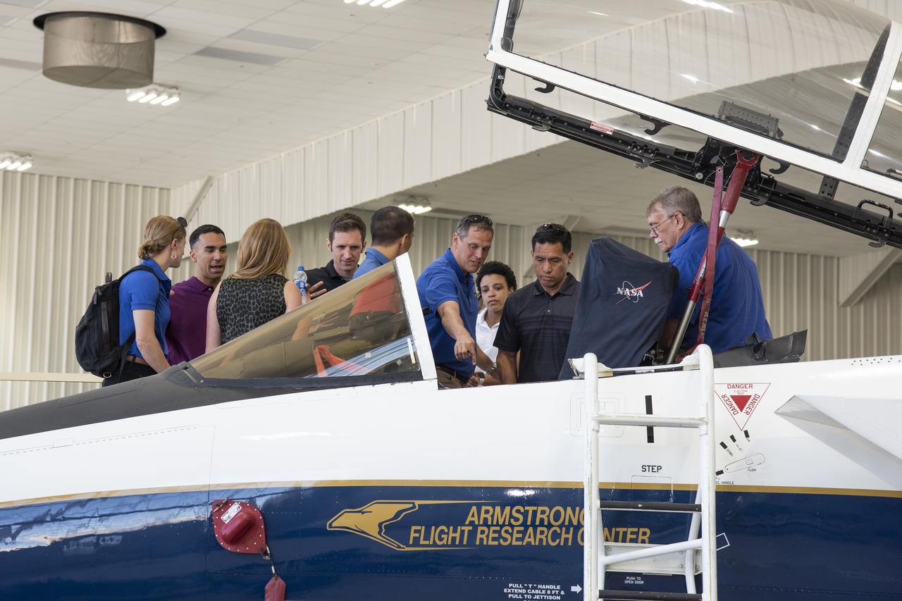
NASA's 2017 astronaut candidates toured aircraft hangar at Armstrong Flight Research Center, in Southern California where they checked out a F-15 cockpit. The center is using its fleet of supersonic research support aircraft for sonic boom research, including the F-15, which will fly in tandem with the X-59 QueSST during early flight test stages, and the F-18, which is conducting supersonic research in support of the overall mission.
NASA's 2017 astronaut candidates toured aircraft hangar at Armstrong Flight Research Center, in Southern California where they checked out a F-15 cockpit. The center is using its fleet of supersonic research support aircraft for sonic boom research, including the F-15, which will fly in tandem with the X-59 QueSST during early flight test stages, and the F-18, which is conducting supersonic research in support of the overall mission.
NASA’s 2017 astronaut candidates toured aircraft hangar at Armstrong Flight Research Center, in Southern California where they checked out a F-15 cockpit. The center is using its fleet of supersonic research support aircraft for sonic boom research, including the F-15, which will fly in tandem with the X-59 QueSST during early flight test stages, and the F-18, which is conducting supersonic research in support of the overall mission.
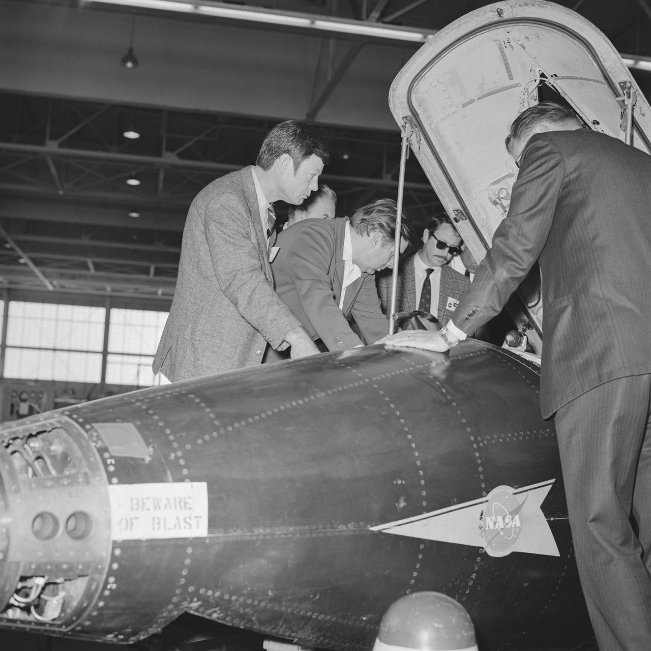
The 1960s Star Trek television series’ cast members visit NASA Dryden Flight Research Center, now Armstrong, in 1967. Chief Medical Officer Leonard ‘Bones’ McCoy played by DeForest Kelley and the show’s creator Gene Roddenberry receive briefing on X-15 cockpit as they view inside.

NASA’s 2017 astronaut candidates (L to R) Jessica Watkins, Zena Cardman, Kayla Barron toured aircraft hangar at Armstrong Flight Research Center, in Southern California where they were briefed on the use of Armstrong's F-15 and F-18 aircraft for studying sonic booms. The aircraft will be used during the development of the low-boom X-59 aircraft that is planned to fly supersonically over land, which is not allowed at this time because of the loud noise created when flying beyond the speed of sound.
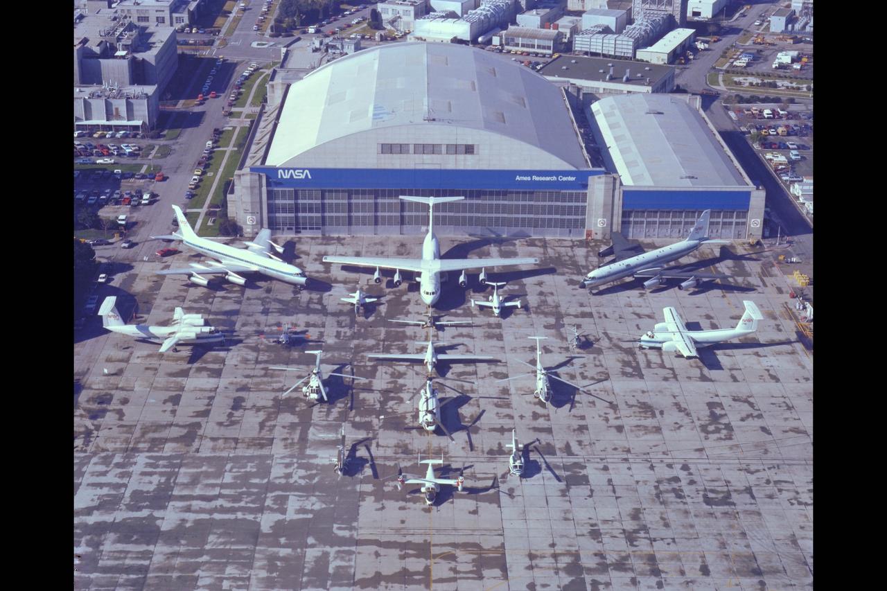
NASA Aircraft on ramp (Aerial view) Sides: (L) QSRA (R) C-8A AWJSRA - Back to Front: CV-990 (711) C-141 KAO, CV-990 (712) Galileo, T-38, YO-3A, Lear Jet, X-14, U-2, OH-6, CH-47, SH-3G, RSRA, AH-1G, XV-15, UH-1H
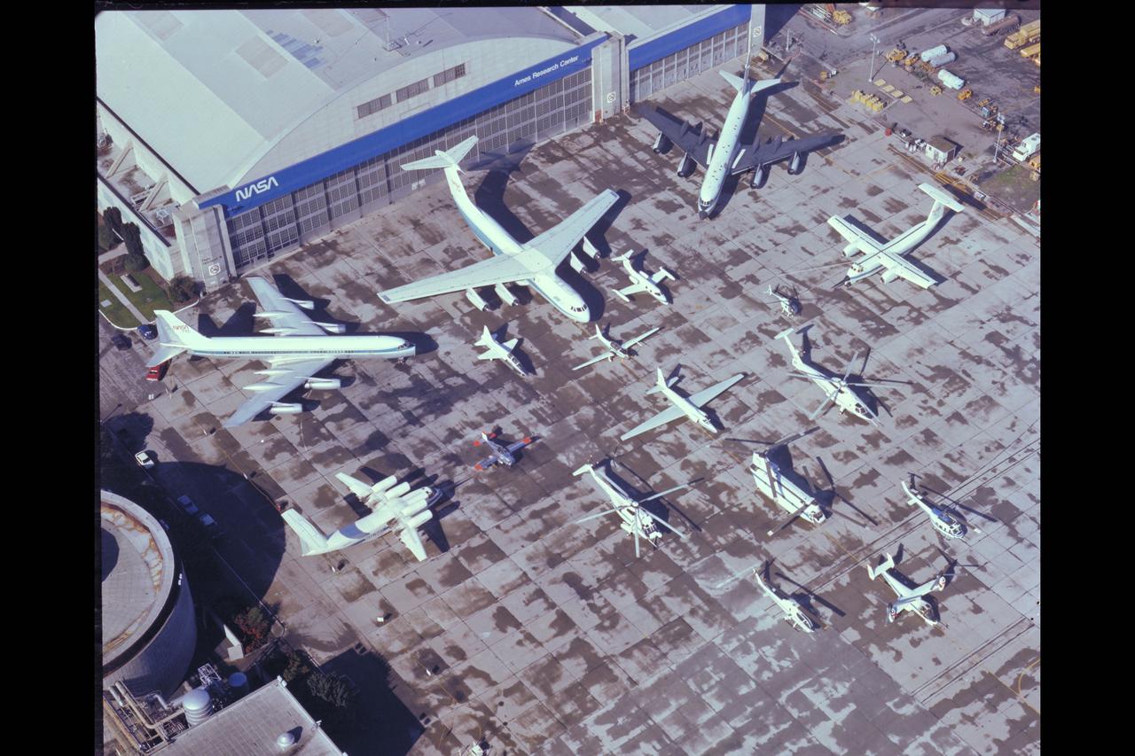
NASA Aircraft on ramp (Aerial view) Sides: (L) QSRA (R) C-8A AWJSRA - Back to Front: CV-990 (711) C-141 KAO, CV-990 (712) Galileo, T-38, YO-3A, Lear Jet, X-14, U-2, OH-6, CH-47, SH-3G, RSRA, AH-1G, XV-15, UH-1H
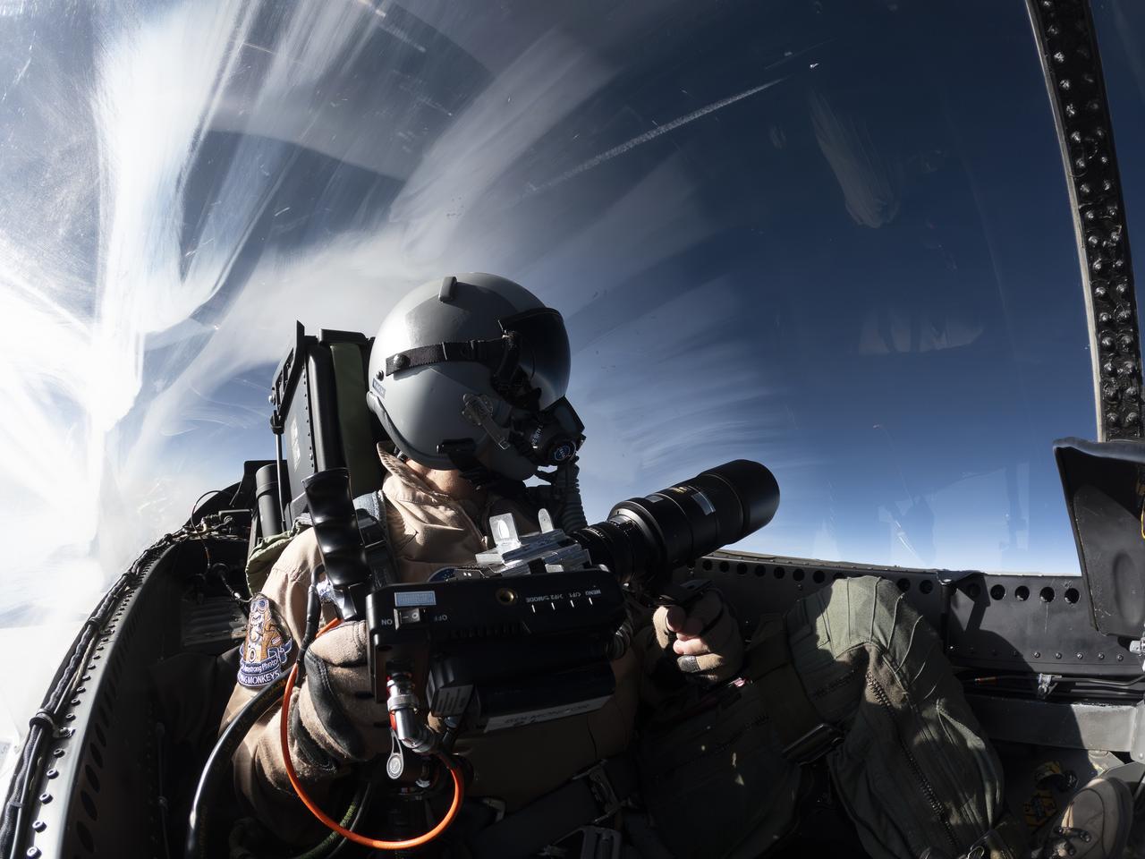
NASA Photographer Carla Thomas holds the Airborne Schlieren Photography System (ASPS), aiming it out the window in flight. The ASPS uses a photographic method called schlieren imaging, capable of visualizing changes in air density and revealing shock waves and air flow patterns around moving objects. The system is one of several tools validated during recent dual F-15 flights at NASA’s Armstrong Flight Research Center in Edwards, California, in support of NASA’s Quesst mission, ahead of the X-59’s first flight.

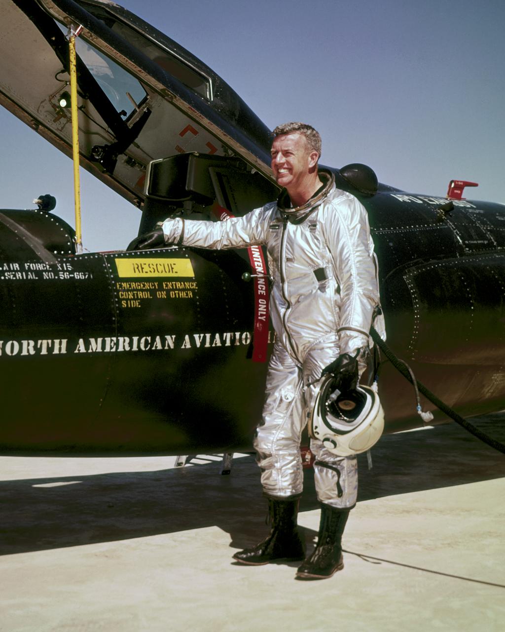
NASA research pilot Bill Dana stands in front of the HL-10 Lifting Body following his first glide flight on April 25, 1969. Dana later retired as Chief Engineer at NASA's Dryden Flight Research Center, (called the NASA Flight Research Center in 1969). Prior to his lifting body assignment, Dana flew the X-15 research airplane. He flew the rocket-powered aircraft 16 times, reaching a top speed of 3,897 miles per hour and a peak altitude of 310,000 feet (almost 59 miles high).
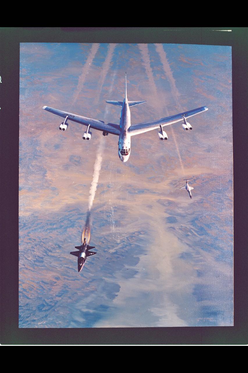
Artist: W.S. Phillips Aeronautics Art: X-15 Hypersonic Final (HQ ref: 84-HC-281 & 84-H-285)
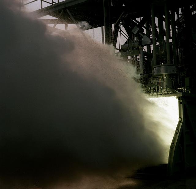
This photodepicts a 15 K Fastrac motor ignition test performed at Marshall Test Stand-116. The Fastrac motor is an alternative low-cost engine which is being developed and tested at Marshall. This engine was to eventually be used on an X-34 launchvehicle. The X-34 program was cancelled in 2001.
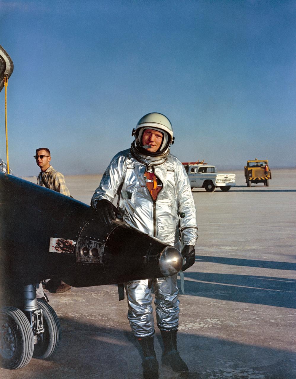
S63-19148 (1963) --- Neil A. Armstrong, a civilian, was a member of the second group of astronauts selected by the National Aeronautics and Space Administration. Armstrong was one of the nine picked in September, 1962. He was an aeronautical research pilot before becoming an astronaut.
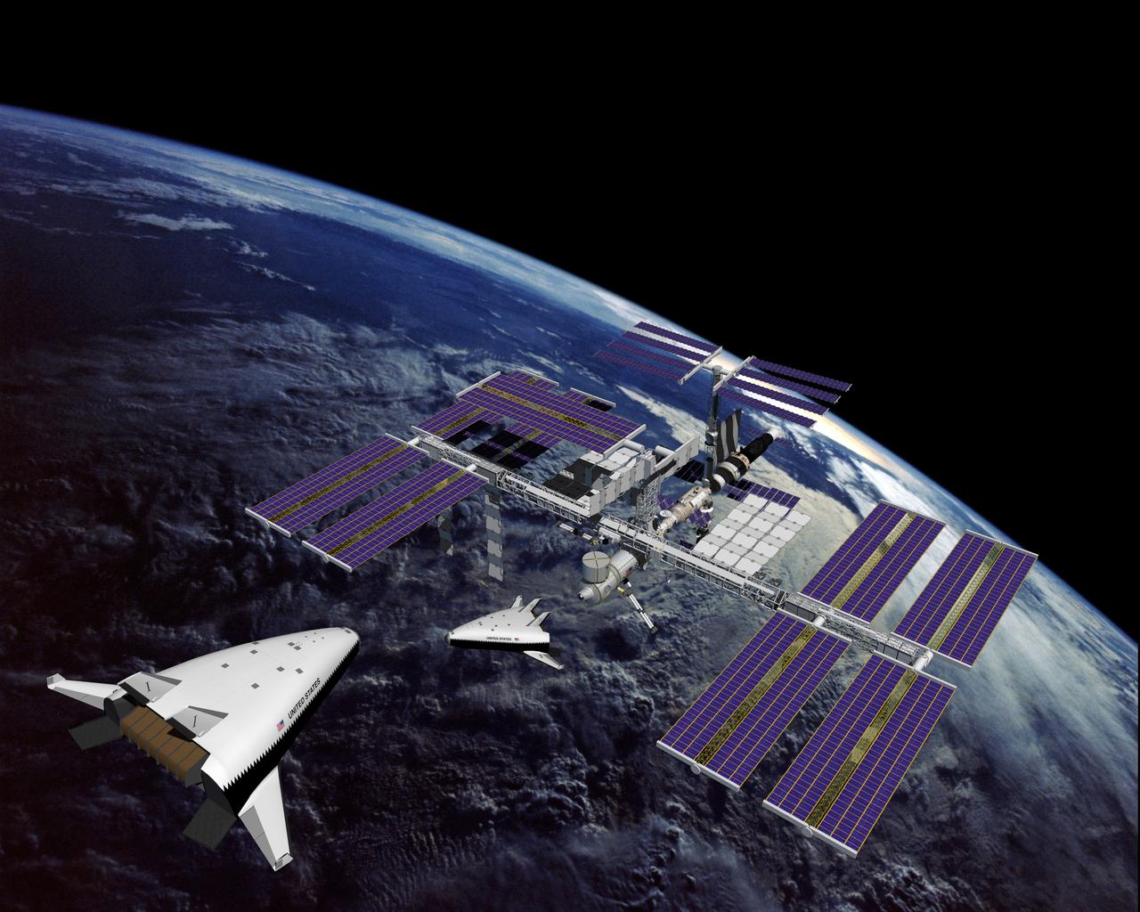
This is an artist's concept of the completely operational International Space Station being approached by an X-33 Reusable Launch Vehicle (RLV). The X-33 program was designed to pave the way to a full-scale, commercially developed RLV as the flagship technology demonstrator for technologies that would lower the cost of access to space. It is unpiloted, taking off vertically like a rocket, reaching an altitude of up to 60 miles and speeds between Mach 13 and 15, and landing horizontally like an airplane. The X-33 program was cancelled in 2001.
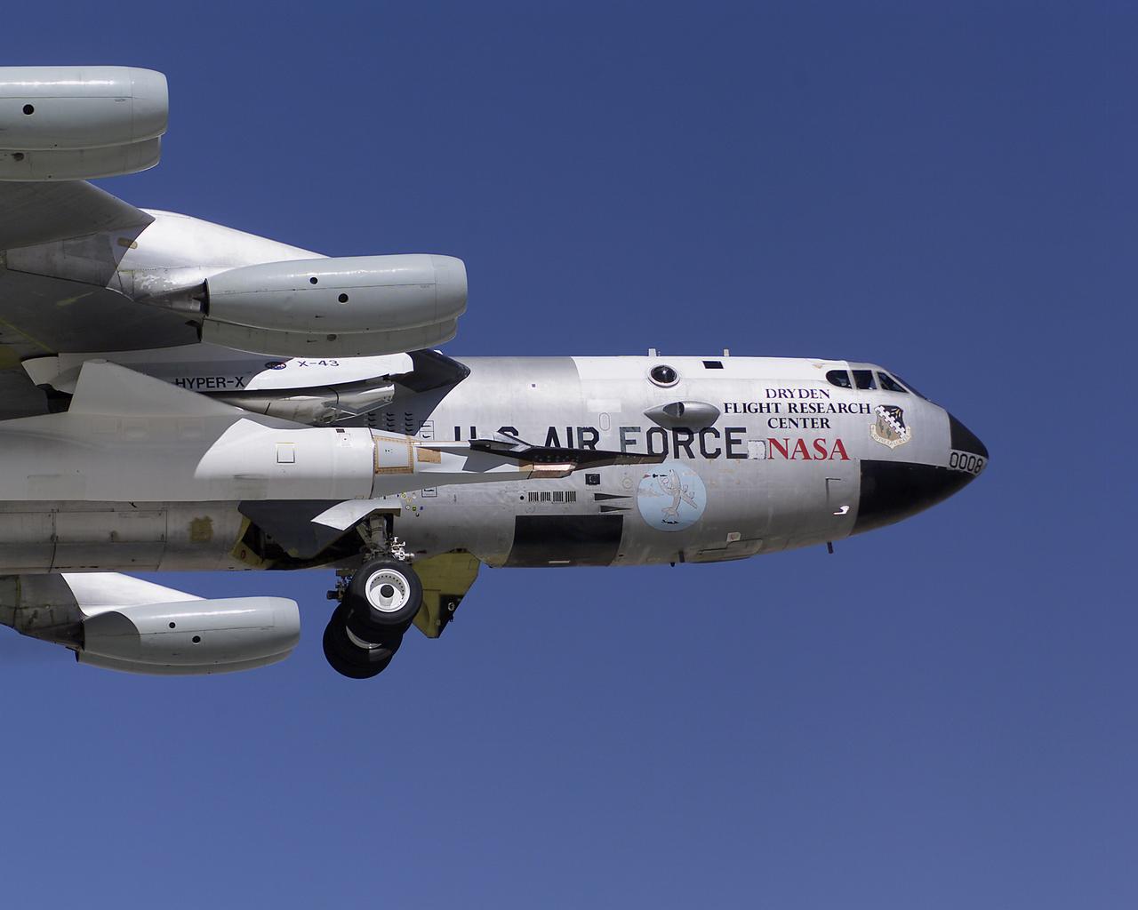
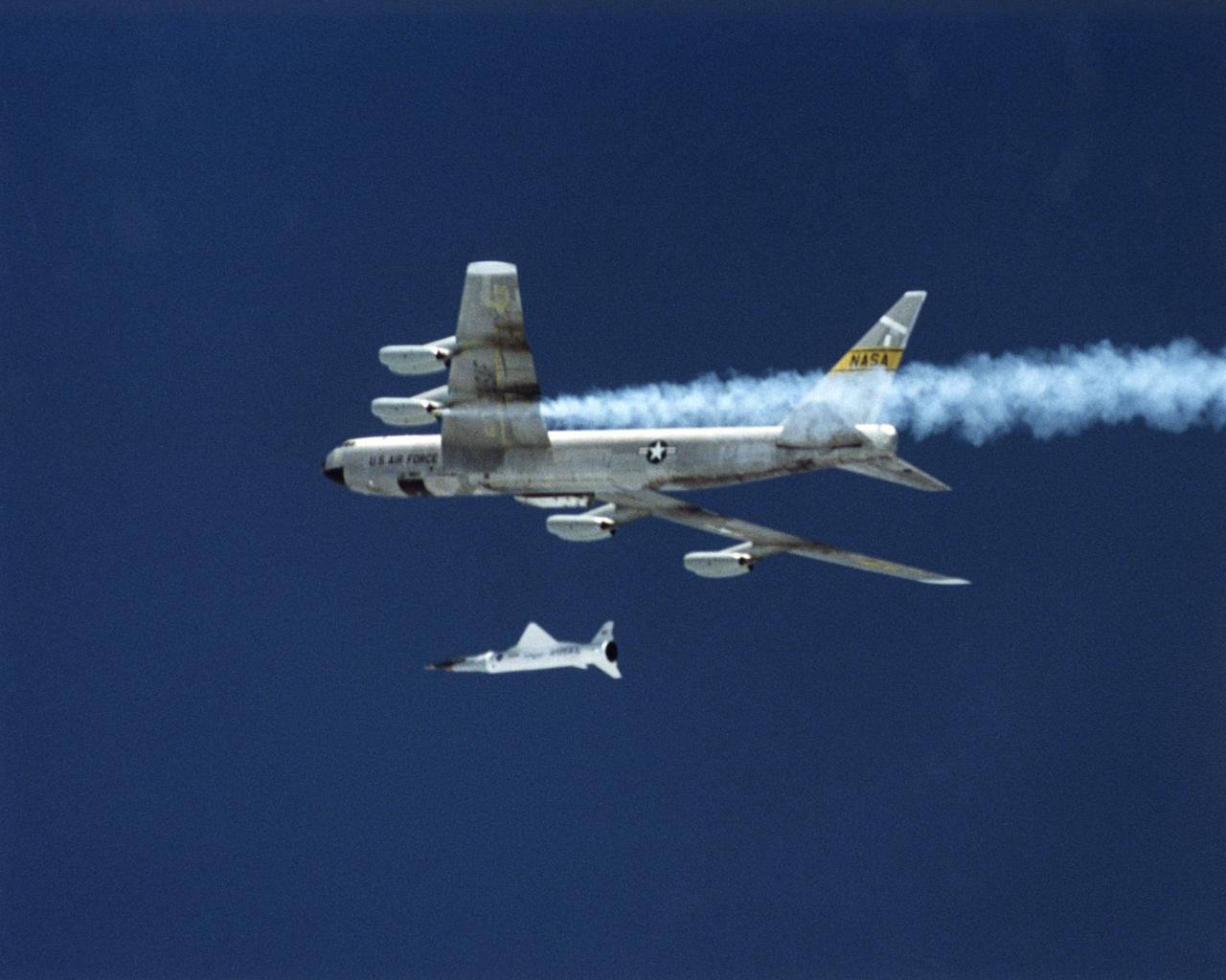
Attached to the same B-52B mothership that once launched X-15 research aircraft in the 1960s, NASA's third X-43A performed a captive carry evaluation flight from Edwards Air Force Base, California on September 27, 2004. The X-43 remained mated to the B-52 throughout this mission, intended to check its readiness for launch scheduled later in the fall.
Attached to the same B-52B mothership that once launched X-15 research aircraft in the 1960s, NASA's third X-43A performed a captive carry evaluation flight from Edwards Air Force Base, California on September 27, 2004. The X-43 remained mated to the B-52 throughout this mission, intended to check its readiness for launch scheduled later in the fall.
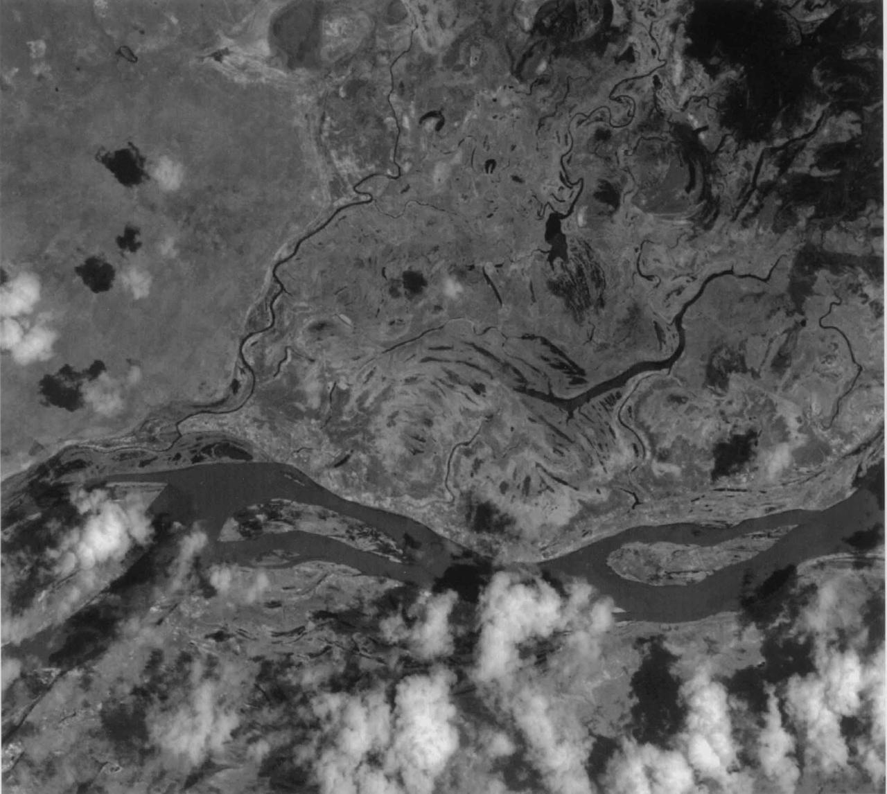
This image of the San Francisco River channel, and its surrounding flood zone, in Brazil was acquired by band 3N of ASTER's Visible/Near Infrared sensor. The surrounding area along the river channel in light gray to white could be covered by dense tropical rain forests. The water surface of the San Francisco River shows rather gray color as compared to small lakes and tributaries, which could indicate that the river water is contaminated by suspended material. The size of image: 20 km x 20 km approx., ground resolution 15 m x 15 m approximately. http://photojournal.jpl.nasa.gov/catalog/PIA02451
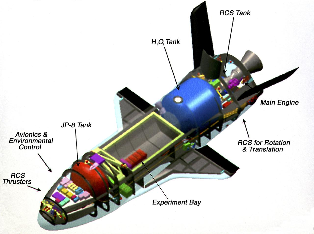
This photograph is an artist's cutaway view of the X-37 flight demonstrator showing its components. The X-37 experimental launch vehicle is roughly 27.5 feet (8.3 meters) long and 15 feet (4.5 meters) in wingspan. Its experiment bay is 7 feet (2.1 meters) long and 4 feet (1.2 meters) in diameter. Designed to operate in both the orbital and reentry phases of flight, the X-37 will increase both safety and reliability, while reducing launch costs from $10,000 per pound to $1000 per pound. The X-37 can be carried into orbit by the Space Shuttle or be launched by an expendable rocket. Managed by Marshall Space Flight Center and built by the Boeing Company, the X-37 is scheduled to fly two orbital missions in 2002/2003 to test the reusable launch vehicle technologies.
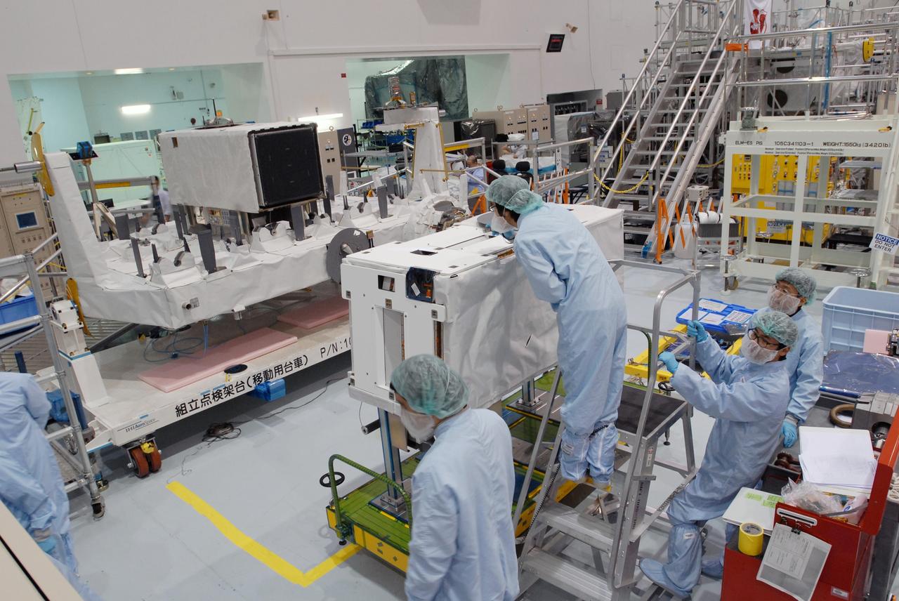
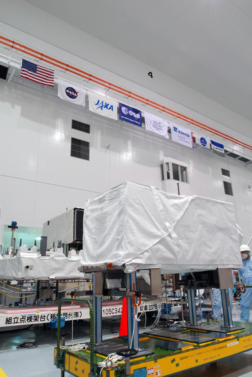
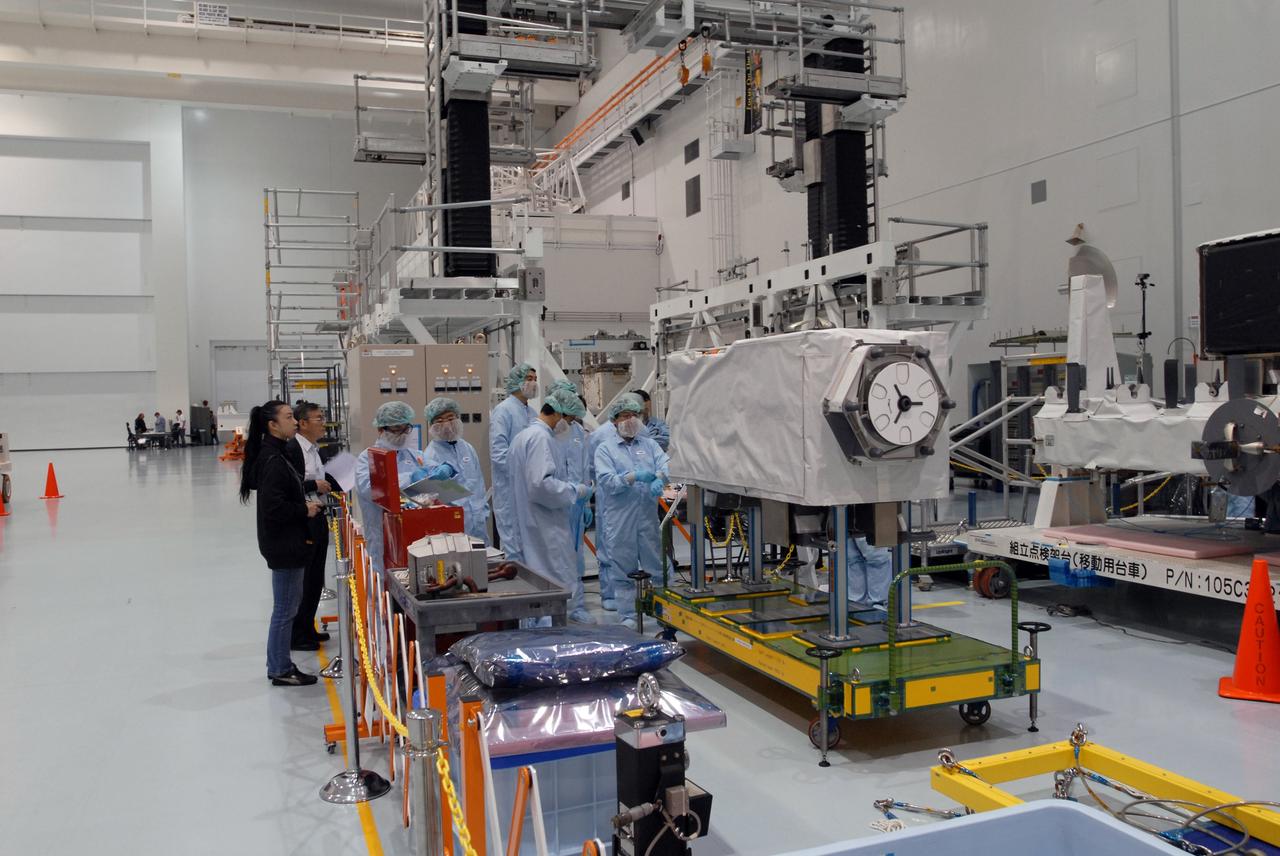
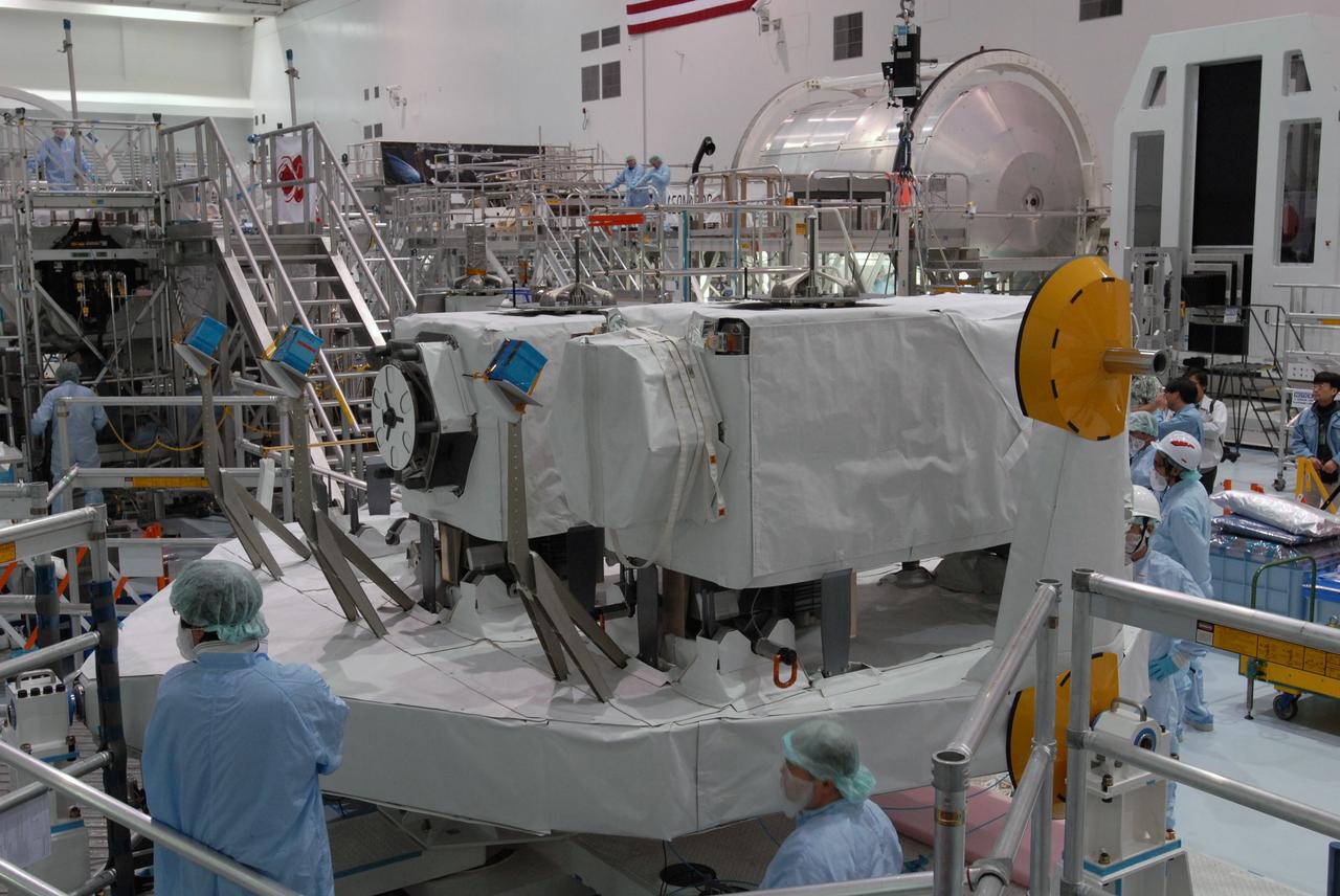
CAPE CANAVERAL, Fla. -- In the Space Station Processing Facility at NASA's Kennedy Space Center in Florida, workers check the MAXI (Monitor of All-sky X-ray Image) before it is installed on the Japanese Experiment Module's Experiment Logistics Module-Exposed Section, or ELM-ES. The MAXI is part of space shuttle Endeavour's payload on the STS-127 mission. Using X-ray slit cameras with high sensitivity, the MAXI will continuously monitor astronomical X-ray objects over a broad energy band (0.5 to 30 keV). Endeavour is targeted to launch May 15. Photo credit: NASA/Jim Grossmann
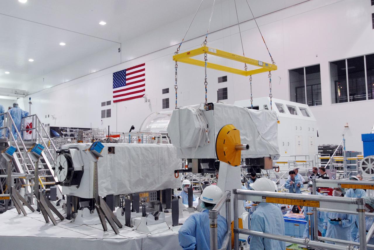
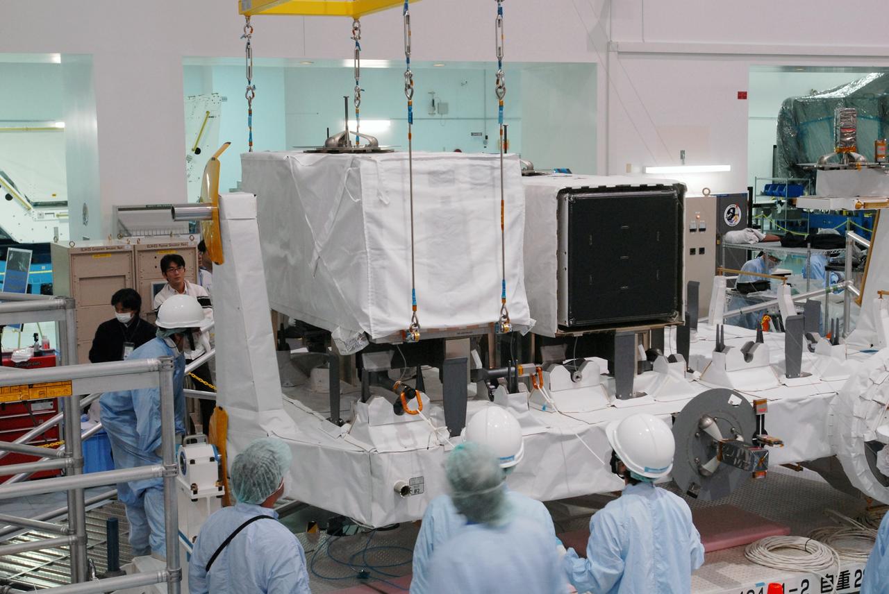
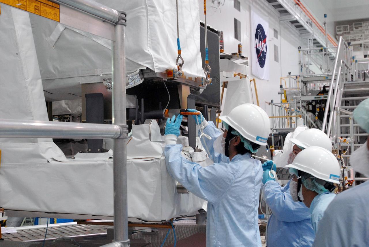
CAPE CANAVERAL, Fla. -- In the Space Station Processing Facility at NASA's Kennedy Space Center in Florida, a crane lifts the MAXI (Monitor of All-sky X-ray Image) to move it onto the Japanese Experiment Module's Experiment Logistics Module-Exposed Section, or ELM-ES, where it will be installed. The MAXI is part of space shuttle Endeavour's payload on the STS-127 mission. Using X-ray slit cameras with high sensitivity, the MAXI will continuously monitor astronomical X-ray objects over a broad energy band (0.5 to 30 keV). Endeavour is targeted to launch May 15. Photo credit: NASA/Jim Grossmann
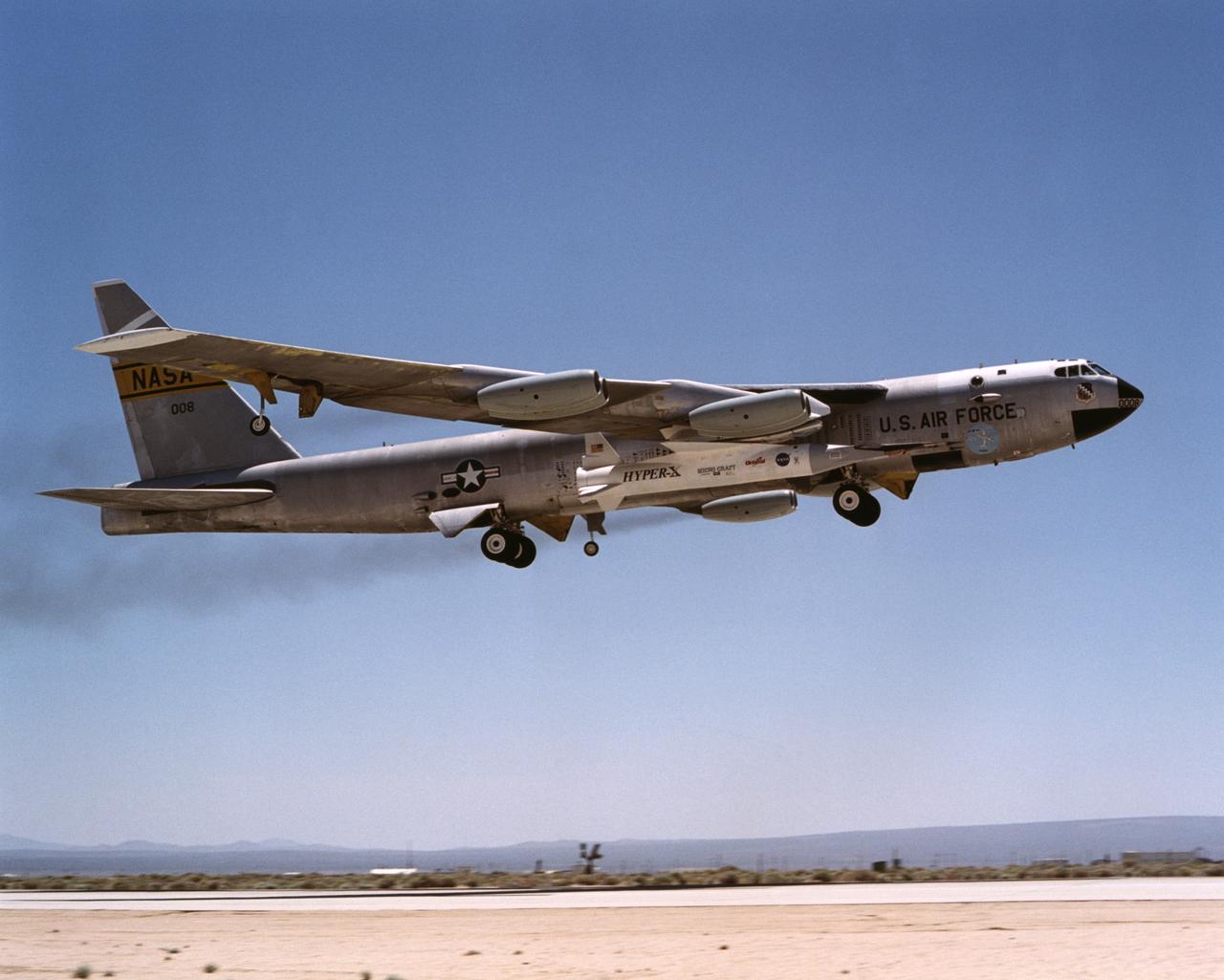
Hitching a ride on the same B-52 mother ship that once launched X-15 research aircraft in the 1960s, NASA's X-43A scramjet and it's Pegasus booster rocket performed a captive carry evaluation flight from Edwards Air Force Base, California, January 26, 2004. The X-43 and it's booster remained mated to the B-52 throughout this mission, intended to check its readiness for launch. The hydrogen-fueled aircraft is autonomous and has a wingspan of approximately 5 feet, measures 12 feet long and weighs about 2,800 pounds.
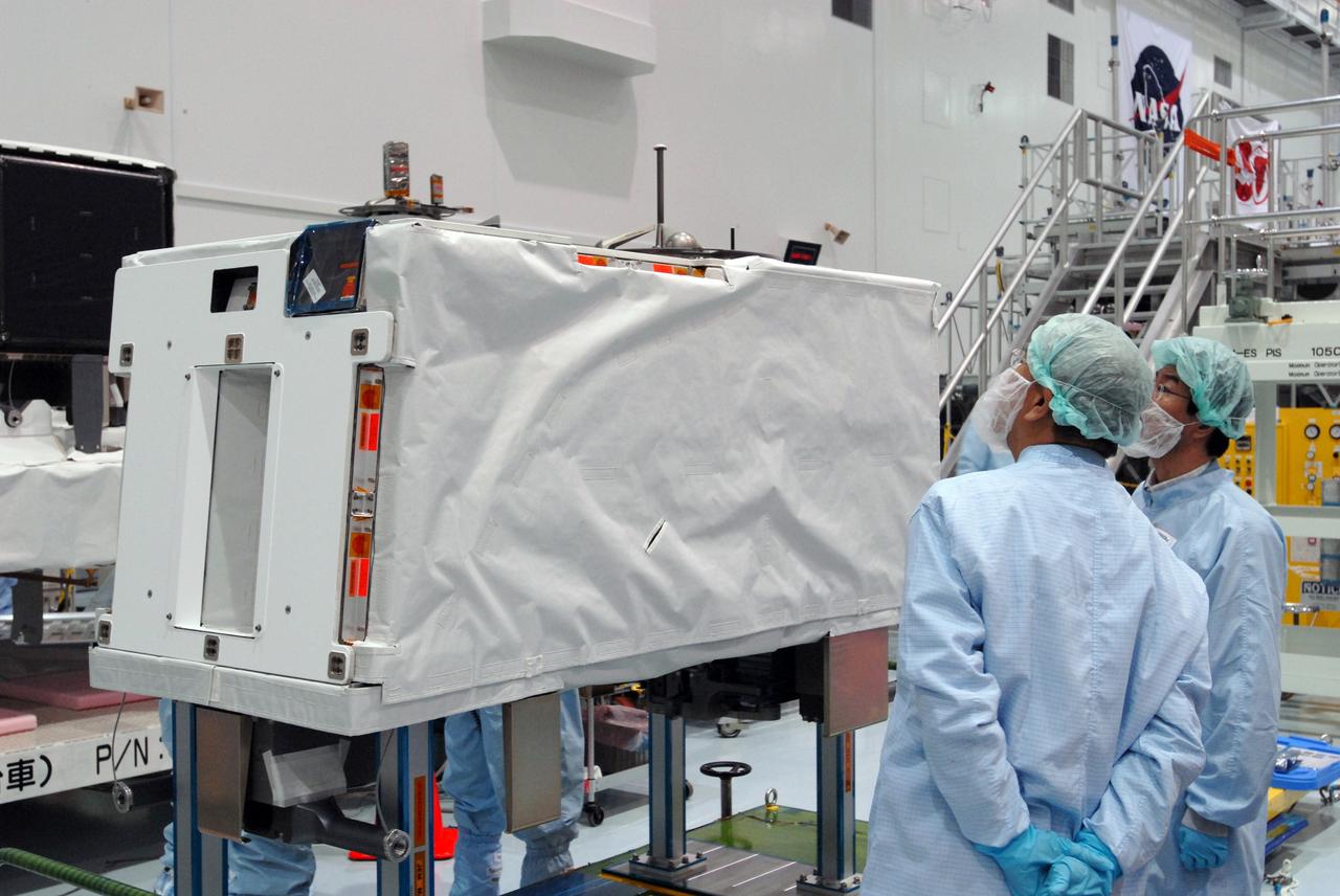
CAPE CANAVERAL, Fla. -- In the Space Station Processing Facility at NASA's Kennedy Space Center in Florida, the MAXI (Monitor of All-sky X-ray Image) is waiting to be installed on the Japanese Experiment Module's Experiment Logistics Module-Exposed Section, or ELM-ES. The MAXI is part of space shuttle Endeavour's payload on the STS-127 mission. Using X-ray slit cameras with high sensitivity, the MAXI will continuously monitor astronomical X-ray objects over a broad energy band (0.5 to 30 keV). Endeavour is targeted to launch May 15. Photo credit: NASA/Jim Grossmann
CAPE CANAVERAL, Fla. -- In the Space Station Processing Facility at NASA's Kennedy Space Center in Florida, a crane lifts the MAXI (Monitor of All-sky X-ray Image) to move it onto the Japanese Experiment Module's Experiment Logistics Module-Exposed Section, or ELM-ES, where it will be installed. The MAXI is part of space shuttle Endeavour's payload on the STS-127 mission. Using X-ray slit cameras with high sensitivity, the MAXI will continuously monitor astronomical X-ray objects over a broad energy band (0.5 to 30 keV). Endeavour is targeted to launch May 15. Photo credit: NASA/Jim Grossmann
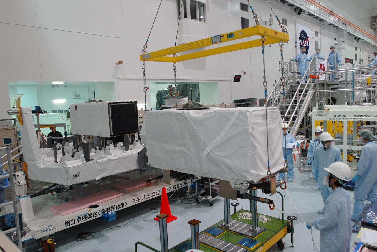
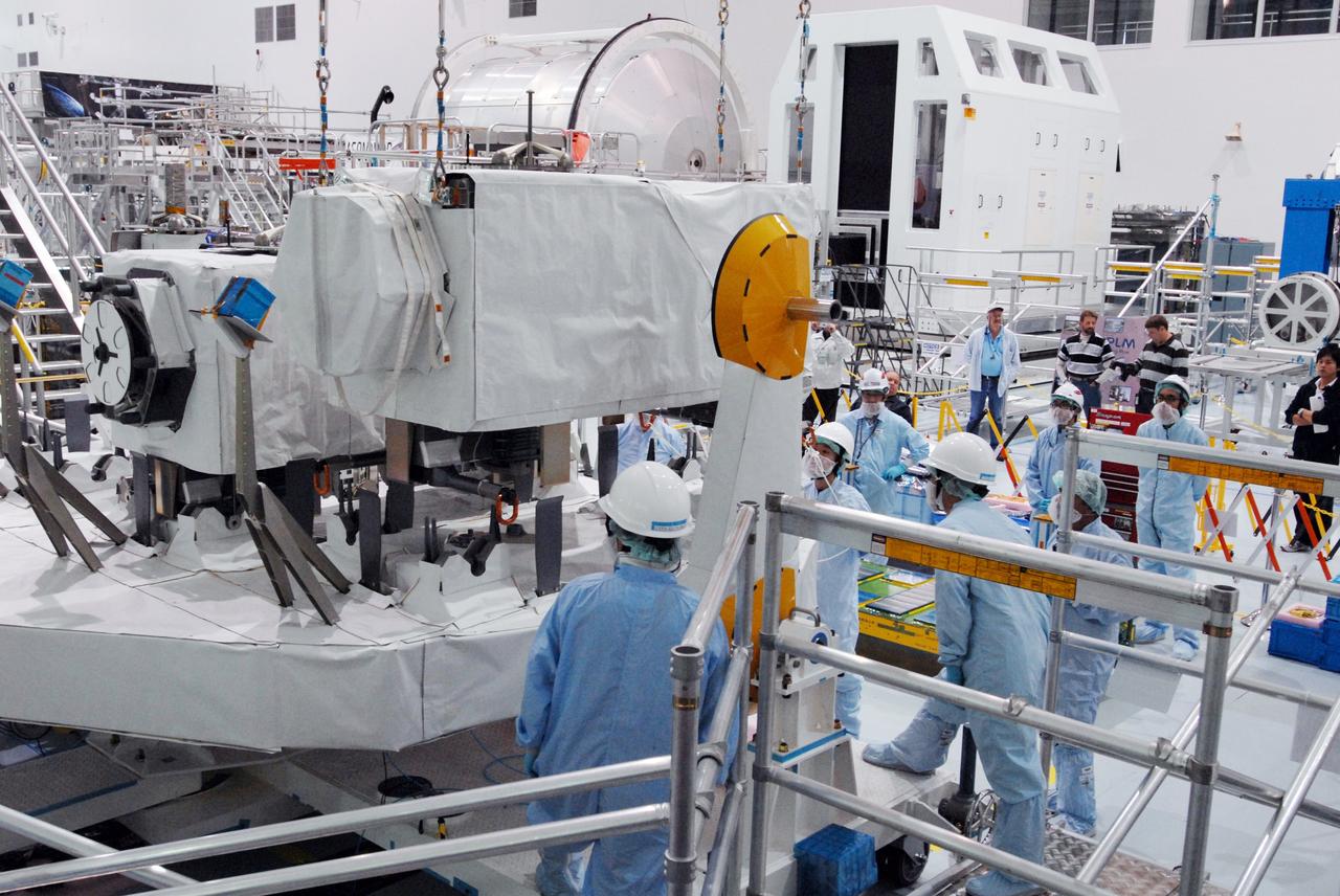
CAPE CANAVERAL, Fla. -- In the Space Station Processing Facility at NASA's Kennedy Space Center in Florida, the MAXI (Monitor of All-sky X-ray Image) is moved toward the Japanese Experiment Module's Experiment Logistics Module-Exposed Section, or ELM-ES, where it will be installed. The MAXI is part of space shuttle Endeavour's payload on the STS-127 mission. Using X-ray slit cameras with high sensitivity, the MAXI will continuously monitor astronomical X-ray objects over a broad energy band (0.5 to 30 keV). Endeavour is targeted to launch May 15. Photo credit: NASA/Jim Grossmann
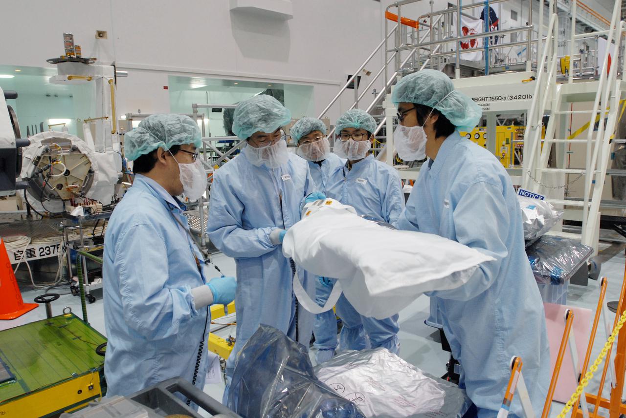
CAPE CANAVERAL, Fla. -- In the Space Station Processing Facility at NASA's Kennedy Space Center in Florida, workers examines equipment for the MAXI (Monitor of All-sky X-ray Image) before it is installed on the Japanese Experiment Module's Experiment Logistics Module-Exposed Section, or ELM-ES. The MAXI is part of space shuttle Endeavour's payload on the STS-127 mission. Using X-ray slit cameras with high sensitivity, the MAXI will continuously monitor astronomical X-ray objects over a broad energy band (0.5 to 30 keV). Endeavour is targeted to launch May 15. Photo credit: NASA_Jim Grossmann
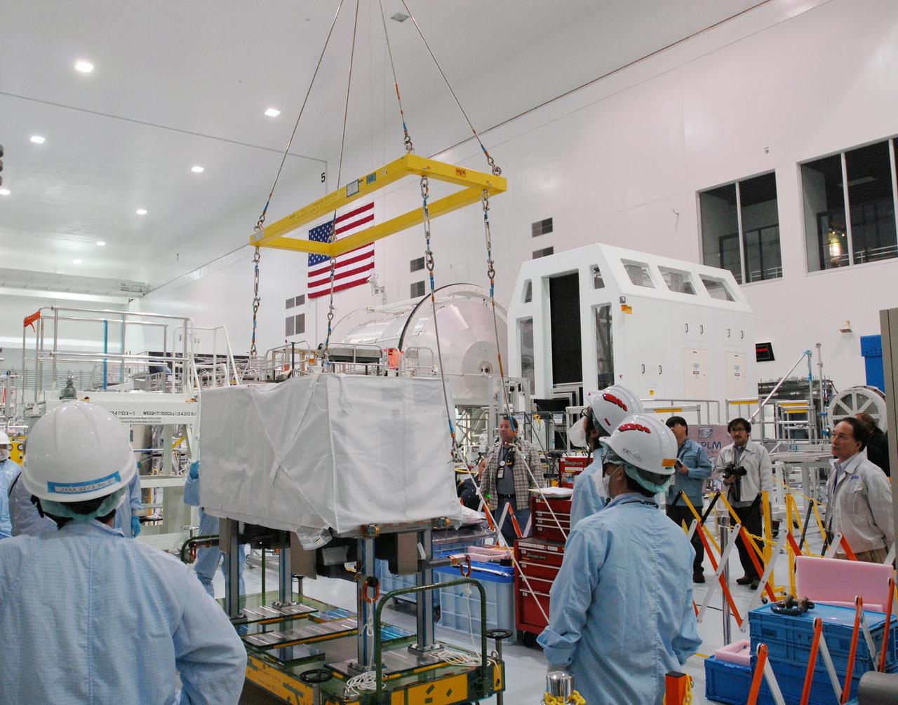
CAPE CANAVERAL, Fla. -- In the Space Station Processing Facility at NASA's Kennedy Space Center in Florida, a crane is moved over the MAXI (Monitor of All-sky X-ray Image). The crane will lift the MAXI onto the Japanese Experiment Module's Experiment Logistics Module-Exposed Section, or ELM-ES, where it will be installed. The MAXI is part of space shuttle Endeavour's payload on the STS-127 mission. Using X-ray slit cameras with high sensitivity, the MAXI will continuously monitor astronomical X-ray objects over a broad energy band (0.5 to 30 keV). Endeavour is targeted to launch May 15. Photo credit: NASA/Jim Grossmann
Hitching a ride on the same B-52 mother ship that once launched X-15 research aircraft in the 1960s, NASA's X-43A scramjet and it's Pegasus booster rocket performed a captive carry evaluation flight from Edwards Air Force Base, California, January 26, 2004. The X-43 and it's booster remained mated to the B-52 throughout this mission, intended to check its readiness for launch. The hydrogen-fueled aircraft is autonomous and has a wingspan of approximately 5 feet, measures 12 feet long and weighs about 2,800 pounds.
CAPE CANAVERAL, Fla. -- In the Space Station Processing Facility at NASA's Kennedy Space Center in Florida, the MAXI (Monitor of All-sky X-ray Image) is waiting to be installed on the Japanese Experiment Module's Experiment Logistics Module-Exposed Section, or ELM-ES. The MAXI is part of space shuttle Endeavour's payload on the STS-127 mission. Using X-ray slit cameras with high sensitivity, the MAXI will continuously monitor astronomical X-ray objects over a broad energy band (0.5 to 30 keV). Endeavour is targeted to launch May 15. Photo credit: NASA/Jim Grossmann
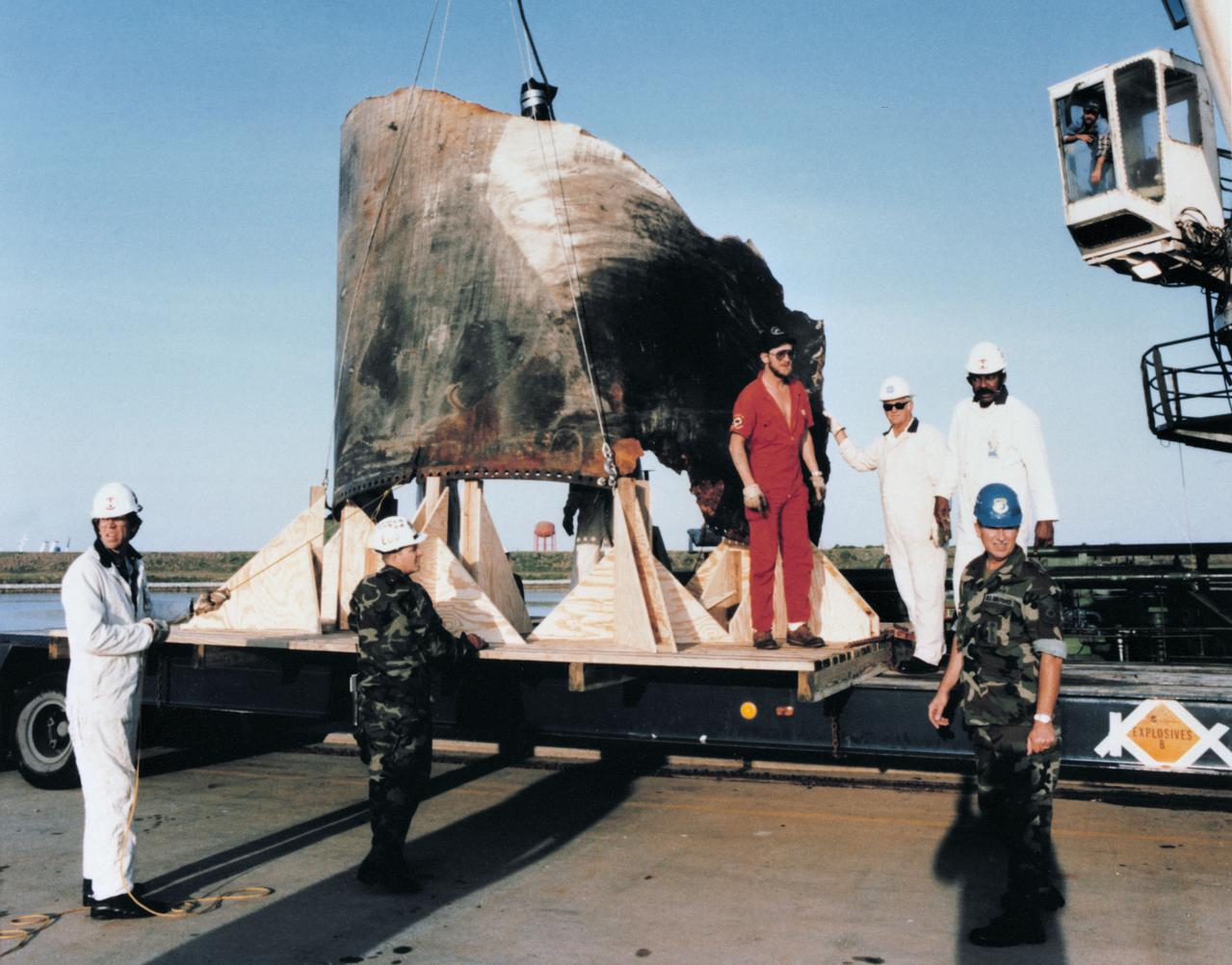
S86-30504 (16 April 1986) --- A 4,000 pound, 11' x 20' piece of the aft center segment tang joint of the space shuttle Challenger's right-hand solid rocket booster is off loaded from the Stena Workhorse after its recovery on April 13, 1986. The burned out area is 15" x 28". Photo credit: NASA

S86-30503 (16 April 1986) --- A 4,000 pound, 11' x 20' piece of the aft center segment tang joint of the space shuttle Challenger's right-hand solid rocket booster is off loaded from the Stena Workhorse after its recovery on April 13, 1986. The burned out area is 15" x 28". Photo credit: NASA
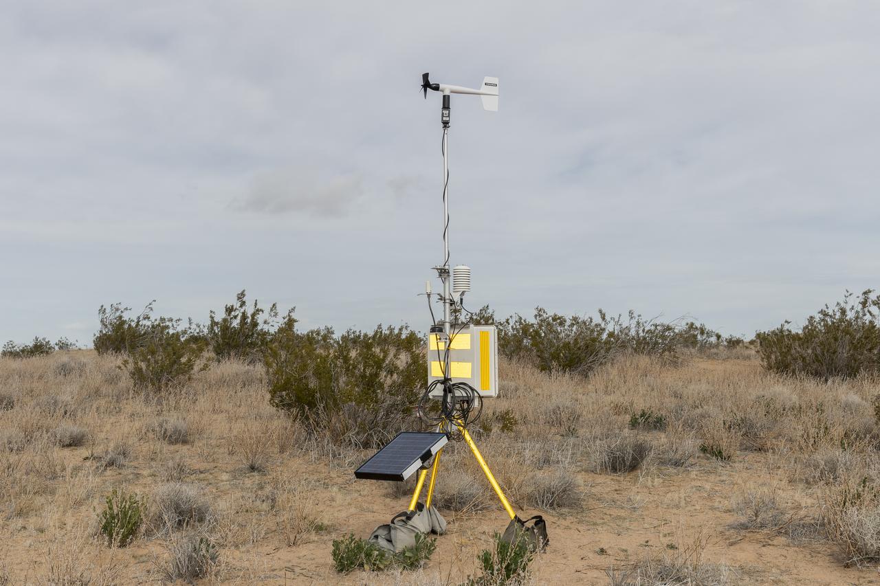
The Quesst mission recently completed testing of operations and equipment to be used in recording the sonic thumps of the X-59. Researchers used three weather towers and a sonic anemometer to collect weather and atmospheric data while recording sonic booms generated by an F-15 and an F-18 from NASA’s Armstrong Flight Research Center.

Two NASA F-15 aircraft sit on the ramp at NASA's Armstrong Flight Research Center, in Edwards, California, ahead of dual F-15 flights that validated the integration of three tools – the Airborne Schlieren Photography System (ASPS), the Airborne Location Integrating Geospatial Navigation System (ALIGNS), and shock-sensing probe. Together these tools will measure and visualize the shock waves generated by NASA's X-59.
The photograph depicts the X-37 neutral buoyancy simulator mockup at Dryden Flight Research Center. The X-37 experimental launch vehicle is roughly 27.5 feet (8.3 meters) long and 15 feet (4.5 meters) in wingspan. Its experiment bay is 7 feet (2.1 meters) long and 4 feet (1.2 meters) in diameter. Designed to operate in both the orbital and reentry phases of flight, the X-37 will increase both safety and reliabiltiy, while reducing launch costs from $10,000 per pound to $1000 per pound. Managed by Marshall Space Flight Center and built by the boeing Company, the X-37 is scheduled to fly two orbital missions in 2002/2003 to test the reusable launch vehicle technologies.
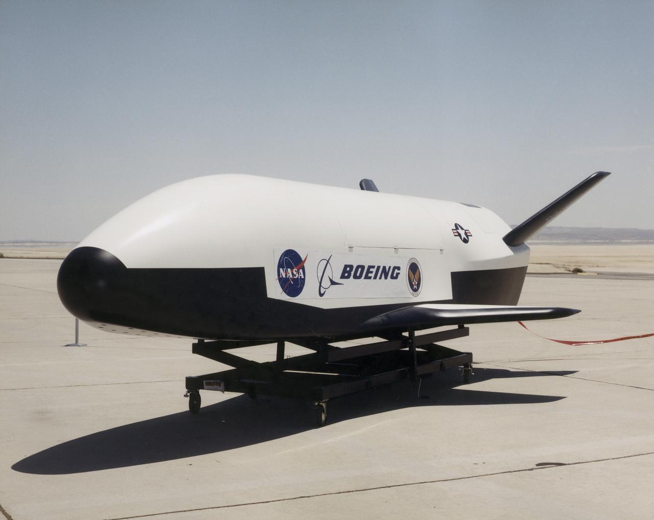
NASA's X-37 Approach and Landing Test Vehicle is installed is a structural facility at Boeing's Huntington Beach, California plant. Tests, completed in July, were conducted to verify the structural integrity of the vehicle in preparation for atmospheric flight tests. Atmospheric flight tests of the Approach and Landing Test Vehicle are scheduled for 2004 and flight tests of the Orbital Vehicle are scheduled for 2006. The X-37 experimental launch vehicle is roughly 27.5 feet (8.3 meters) long and 15 feet (4.5 meters) in wingspan. It's experiment bay is 7 feet (2.1 meters) long and 4 feet (1.2 meters) in diameter. Designed to operate in both the orbital and reentry phases of flight, the X-37 will increase both safety and reliability, while reducing launch costs from $10,000 per pound to $1,000.00 per pound. The X-37 program is managed by the Marshall Space Flight Center and built by the Boeing Company.
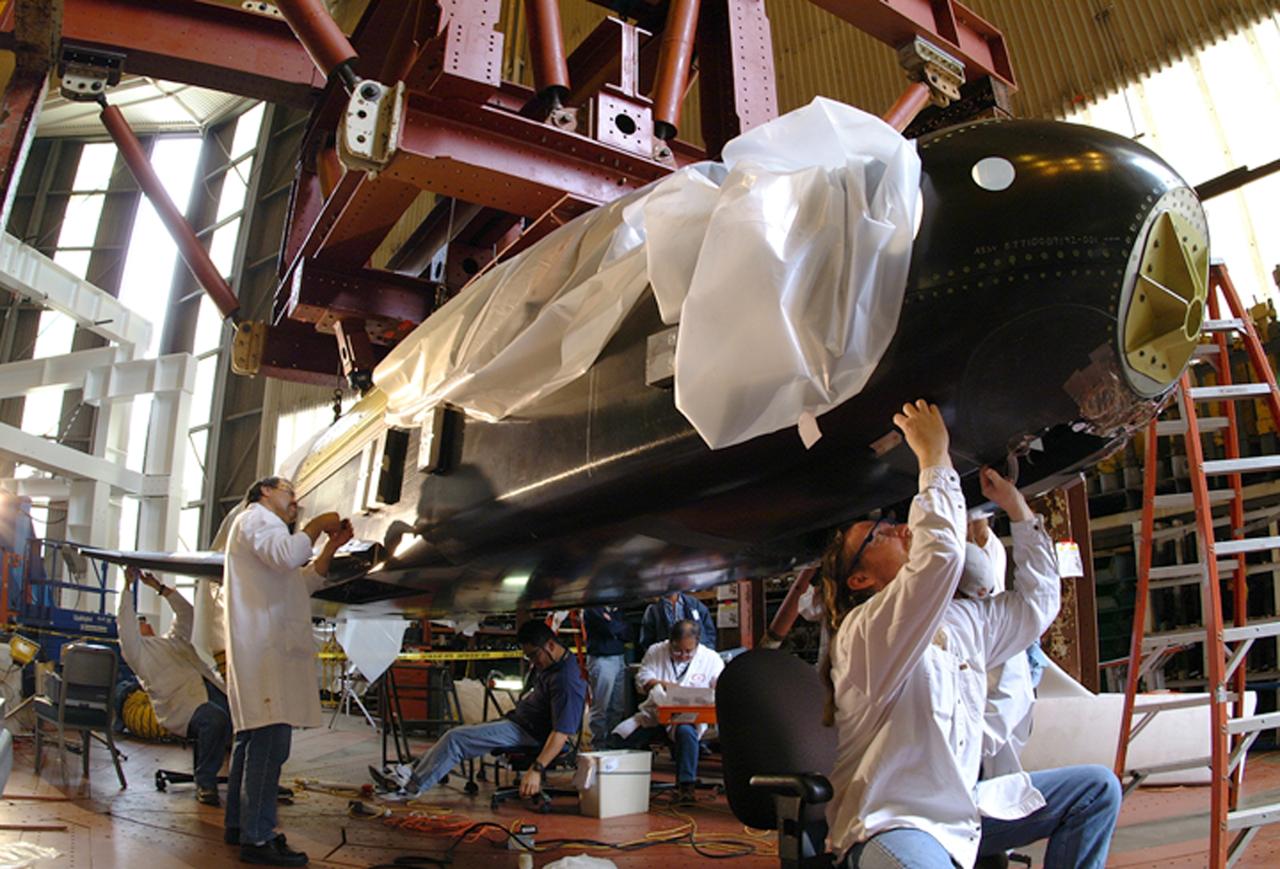
NASA's X-37 Approach and Landing Test Vehicle is installed is a structural facility at Boeing's Huntington Beach, California plant, where technicians make adjustments to composite panels. Tests, completed in July, were conducted to verify the structural integrity of the vehicle in preparation for atmospheric flight tests. Atmospheric flight tests of the Approach and Landing Test Vehicle are scheduled for 2004 and flight tests of the Orbital Vehicle are scheduled for 2006. The X-37 experimental launch vehicle is roughly 27.5 feet (8.3 meters) long and 15 feet (4.5 meters) in wingspan. It's experiment bay is 7 feet (2.1 meters) long and 4 feet (1.2 meters) in diameter. Designed to operate in both the orbital and reentry phases of flight, the X-37 will increase both safety and reliability, while reducing launch costs from $10,000 per pound to $1,000.00 per pound. The X-37 program is managed by the Marshall Space Flight Center and built by the Boeing Company.
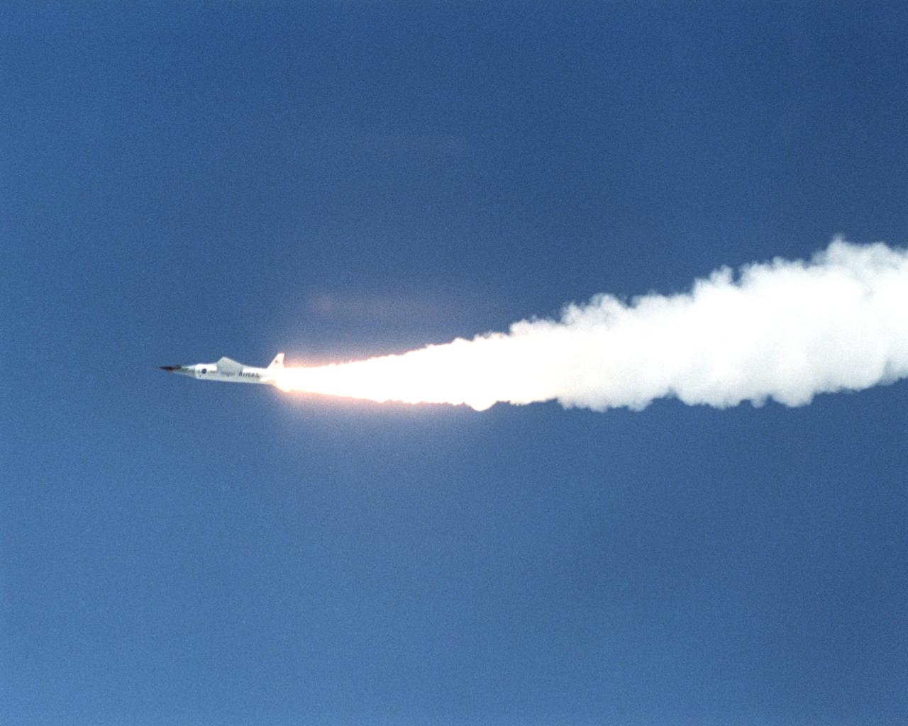
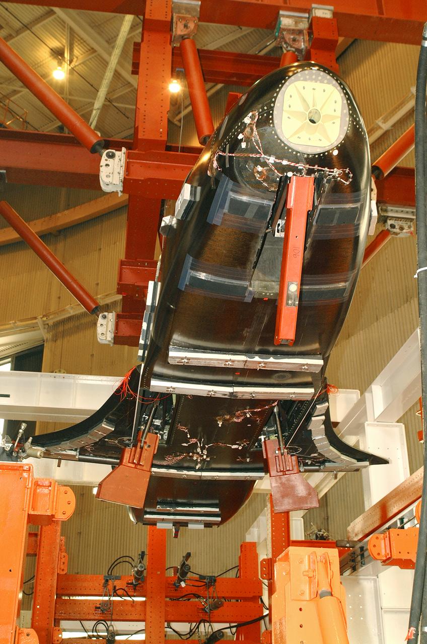
The first X-43A hypersonic research aircraft and its modified Pegasus booster rocket were carried aloft by NASA's NB-52B carrier aircraft from Dryden Flight Research Center at Edwards Air Force Base, Calif., on June 2, 2001 for the first of three high-speed free flight attempts. About an hour and 15 minutes later the Pegasus booster was released from the B-52 to accelerate the X-43A to its intended speed of Mach 7. Before this could be achieved, the combined Pegasus and X-43A "stack" lost control about eight seconds after ignition of the Pegasus rocket motor. The mission was terminated and explosive charges ensured the Pegasus and X-43A fell into the Pacific Ocean in a cleared Navy range area. A NASA investigation board is being assembled to determine the cause of the incident. Work continues on two other X-43A vehicles, the first of which could fly by late 2001. Central to the X-43A program is its integration of an air-breathing "scramjet" engine that could enable a variety of high-speed aerospace craft, and promote cost-effective access to space. The 12-foot, unpiloted research vehicle was developed and built for NASA by MicroCraft Inc., Tullahoma, Tenn. The booster was built by Orbital Sciences Corp. at Chandler, Ariz.

The first X-43A hypersonic research aircraft and its modified Pegasus booster rocket were carried aloft by NASA's NB-52B carrier aircraft from Dryden Flight Research Center at Edwards Air Force Base, Calif., on June 2, 2001 for the first of three high-speed free flight attempts. About an hour and 15 minutes later the Pegasus booster was released from the B-52 to accelerate the X-43A to its intended speed of Mach 7. Before this could be achieved, the combined Pegasus and X-43A "stack" lost control about eight seconds after ignition of the Pegasus rocket motor. The mission was terminated and explosive charges ensured the Pegasus and X-43A fell into the Pacific Ocean in a cleared Navy range area. A NASA investigation board is being assembled to determine the cause of the incident. Work continues on two other X-43A vehicles, the first of which could fly by late 2001. Central to the X-43A program is its integration of an air-breathing "scramjet" engine that could enable a variety of high-speed aerospace craft, and promote cost-effective access to space. The 12-foot, unpiloted research vehicle was developed and built for NASA by MicroCraft Inc., Tullahoma, Tenn. The booster was built by Orbital Sciences Corp. at Chandler, Ariz.
The first X-43A hypersonic research aircraft and its modified Pegasus booster rocket were carried aloft by NASA's NB-52B carrier aircraft from Dryden Flight Research Center at Edwards Air Force Base, Calif., on June 2, 2001 for the first of three high-speed free flight attempts. About an hour and 15 minutes later the Pegasus booster was released from the B-52 to accelerate the X-43A to its intended speed of Mach 7. Before this could be achieved, the combined Pegasus and X-43A "stack" lost control about eight seconds after ignition of the Pegasus rocket motor. The mission was terminated and explosive charges ensured the Pegasus and X-43A fell into the Pacific Ocean in a cleared Navy range area. A NASA investigation board is being assembled to determine the cause of the incident. Work continues on two other X-43A vehicles, the first of which could fly by late 2001. Central to the X-43A program is its integration of an air-breathing "scramjet" engine that could enable a variety of high-speed aerospace craft, and promote cost-effective access to space. The 12-foot, unpiloted research vehicle was developed and built for NASA by MicroCraft Inc., Tullahoma, Tenn. The booster was built by Orbital Sciences Corp. at Chandler, Ariz.
The first X-43A hypersonic research aircraft and its modified Pegasus booster rocket were carried aloft by NASA's NB-52B carrier aircraft from Dryden Flight Research Center at Edwards Air Force Base, Calif., on June 2, 2001 for the first of three high-speed free flight attempts. About an hour and 15 minutes later the Pegasus booster was released from the B-52 to accelerate the X-43A to its intended speed of Mach 7. Before this could be achieved, the combined Pegasus and X-43A "stack" lost control about eight seconds after ignition of the Pegasus rocket motor. The mission was terminated and explosive charges ensured the Pegasus and X-43A fell into the Pacific Ocean in a cleared Navy range area. A NASA investigation board is being assembled to determine the cause of the incident. Work continues on two other X-43A vehicles, the first of which could fly by late 2001. Central to the X-43A program is its integration of an air-breathing "scramjet" engine that could enable a variety of high-speed aerospace craft, and promote cost-effective access to space. The 12-foot, unpiloted research vehicle was developed and built for NASA by MicroCraft Inc., Tullahoma, Tenn. The booster was built by Orbital Sciences Corp. at Chandler, Ariz.
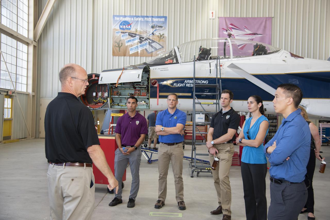
NASA’s 2017 astronaut candidates (L to R) Raja Chari, Bob Hines, Joshua Kutryk, Jasmin Moghbeli, Jonny Kim, and Jessica Watkins toured aircraft hangar at Armstrong Flight Research Center, in Southern California. On the left, NASA’s, X-59 pilot, briefs them on use of F-15 for studying sonic booms during the development of the low-boom X-59 aircraft that is planned to fly supersonically over land. Low-level supersonic flight is not allowed at this time because of the loud noise levels generated when flying beyond the speed of sound.

STS059-86-059 (9-20 April 1994) --- This oblique handheld Hasselblad 70mm photo shows Death Valley, near California's border with Nevada. The valley -- the central feature of Death Valley National Monument -- extends north to south for some 140 miles (225 kilometers). Hemmed in to the east by the Amargosa Range and to the west by the Panamints, its width varies from 5 to 15 miles (8 to 24 kilometers). Using Spaceborne Imaging Radar (SIR-C) and X-band Synthetic Aperture Radar (X-SAR) onboard the Space Shuttle Endeavour, the crew was able to record a great deal of data on this and other sites, as part of NASA's Mission to Planet Earth.
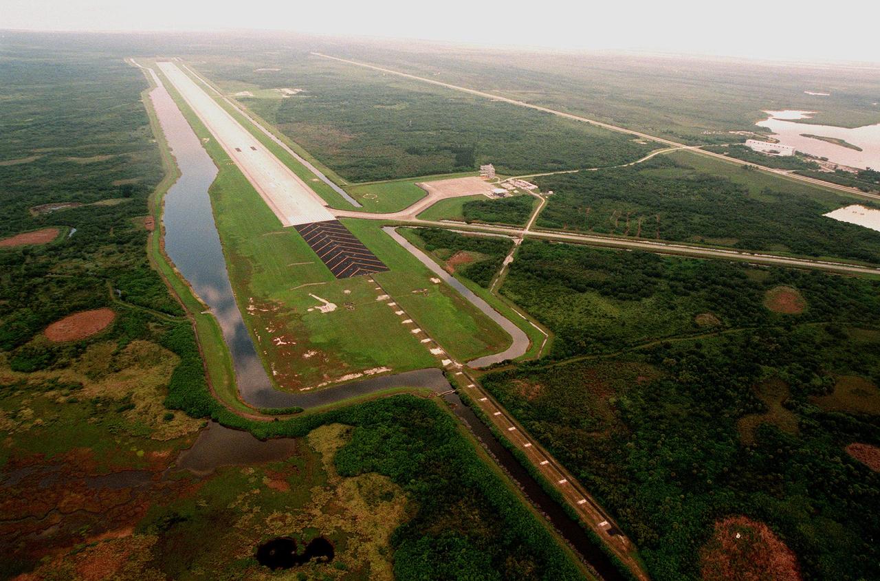
North of the Launch Complex 39 Area, the Shuttle Landing Facility (SLF) stretches to the northwest. One of the largest runways in the world, the runway is located 3.2 km (2 miles) northwest of the Vehicle Assembly Building and is 4,572 meters (15,000 ft) long and 91.4 meters (300 ft) wide -- about as wide as the length of a football field. It has 305 meters (1000 ft) of paved overruns at each end and the paving thickness is 40.6cm (15 in) at the center. The facility includes a 150 x 168-meter (490 ft x 550 ft) parking apron (at right) and a 3.2-km (2-mile) tow-way connecting it with the Orbiter Processing Facility.
CAPE CANAVERAL, Fla. -- In the Space Station Processing Facility at NASA's Kennedy Space Center in Florida, a crane lowers the MAXI (Monitor of All-sky X-ray Image) onto the Payload Attachment Mechanism on the Japanese Experiment Module's Experiment Logistics Module-Exposed Section, or ELM-ES. It is being installed next to the SEDA-AP (Space Environment Data Acquisition Equipment-Attached Payload). The MAXI and SEDA-AP are part of space shuttle Endeavour's payload on the STS-127 mission. Using X-ray slit cameras with high sensitivity, the MAXI will continuously monitor astronomical X-ray objects over a broad energy band (0.5 to 30 keV). Endeavour is targeted to launch May 15. Photo credit: NASA/Jim Grossmann
CAPE CANAVERAL, Fla. -- In the Space Station Processing Facility at NASA's Kennedy Space Center in Florida, the MAXI (Monitor of All-sky X-ray Image) has been installed next to the SEDA-AP (Space Environment Data Acquisition Equipment-Attached Payload) on the Japanese Experiment Module's Experiment Logistics Module-Exposed Section, or ELM-ES. The MAXI and SEDA-AP are part of space shuttle Endeavour's payload on the STS-127 mission. Using X-ray slit cameras with high sensitivity, the MAXI will continuously monitor astronomical X-ray objects over a broad energy band (0.5 to 30 keV). Endeavour is targeted to launch May 15. Photo credit: NASA/Jim Grossmann
CAPE CANAVERAL, Fla. -- In the Space Station Processing Facility at NASA's Kennedy Space Center in Florida, a worker adjusts placement of the MAXI (Monitor of All-sky X-ray Image) on the Payload Attachment Mechanism on the Japanese Experiment Module's Experiment Logistics Module-Exposed Section, or ELM-ES. It is being installed next to the SEDA-AP (Space Environment Data Acquisition Equipment-Attached Payload). The MAXI and SEDA-AP are part of space shuttle Endeavour's payload on the STS-127 mission. Using X-ray slit cameras with high sensitivity, the MAXI will continuously monitor astronomical X-ray objects over a broad energy band (0.5 to 30 keV). Endeavour is targeted to launch May 15. Photo credit: NASA/Jim Grossmann
CAPE CANAVERAL, Fla. -- In the Space Station Processing Facility at NASA's Kennedy Space Center in Florida, a crane lowers the MAXI (Monitor of All-sky X-ray Image) onto the Payload Attachment Mechanism on the Japanese Experiment Module's Experiment Logistics Module-Exposed Section, or ELM-ES. It is being installed next to the SEDA-AP (Space Environment Data Acquisition Equipment-Attached Payload). The MAXI and SEDA-AP are part of space shuttle Endeavour's payload on the STS-127 mission. Using X-ray slit cameras with high sensitivity, the MAXI will continuously monitor astronomical X-ray objects over a broad energy band (0.5 to 30 keV). Endeavour is targeted to launch May 15. Photo credit: NASA/Jim Grossmann
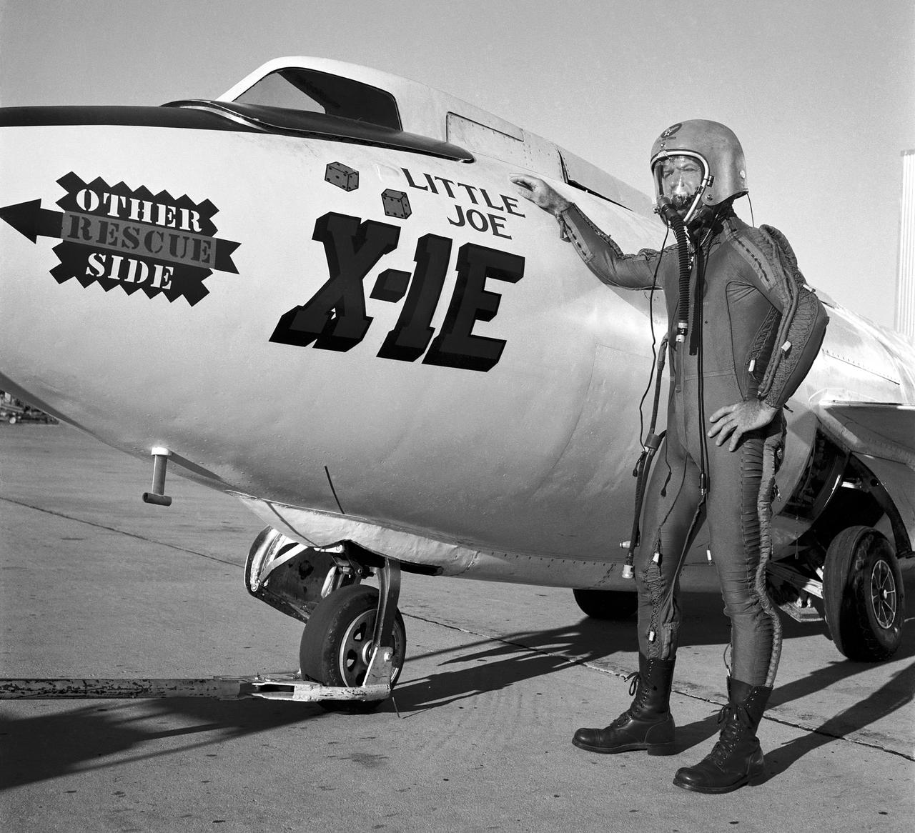
Joe Walker in a pressure suit beside the X-1E at the NASA High-Speed Flight Station, Edwards,California. The dice and "Little Joe" are prominently displayed under the cockpit area. (Little Joe is a dice players slang term for two deuces.) Walker is shown in the photo wearing an early Air Force partial pressure suit. This protected the pilot if cockpit pressure was lost above 50,000 feet. Similar suits were used in such aircraft as B-47s, B-52s, F-104s, U-2s, and the X-2 and D-558-II research aircraft. Five years later, Walker reached 354,200 feet in the X-15. Similar artwork - reading "Little Joe the II" - was applied for the record flight. These cases are two of the few times that research aircraft carried such nose art.

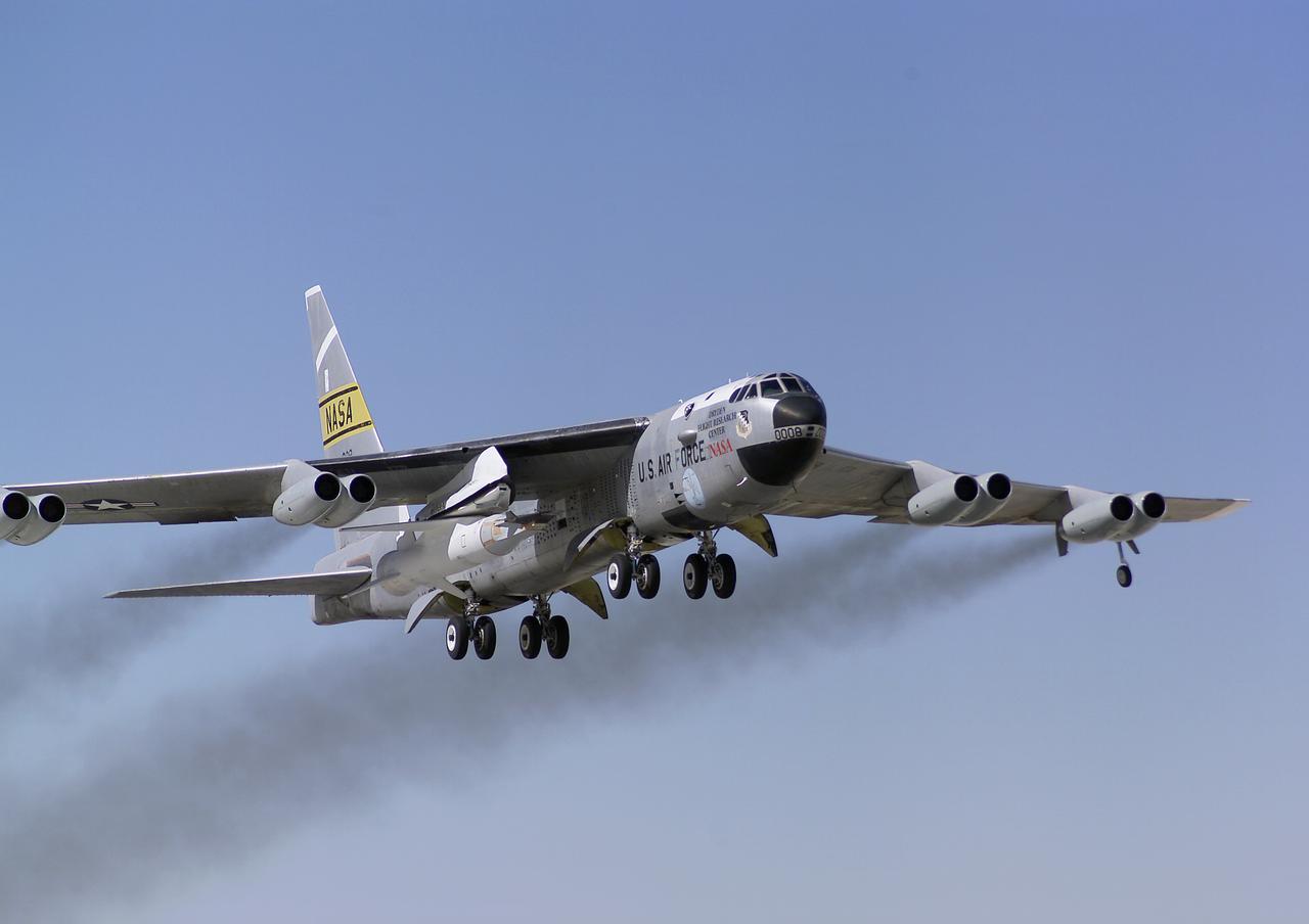
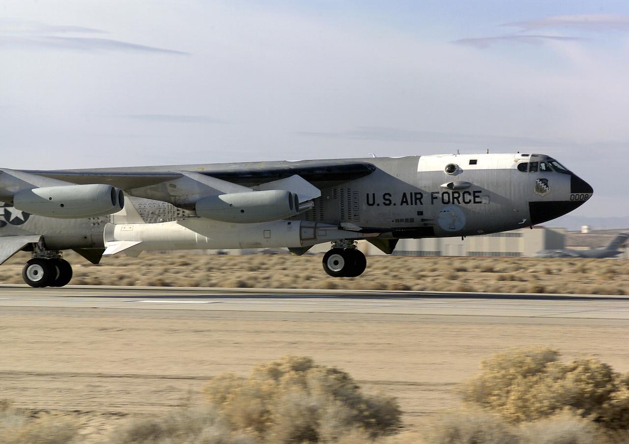
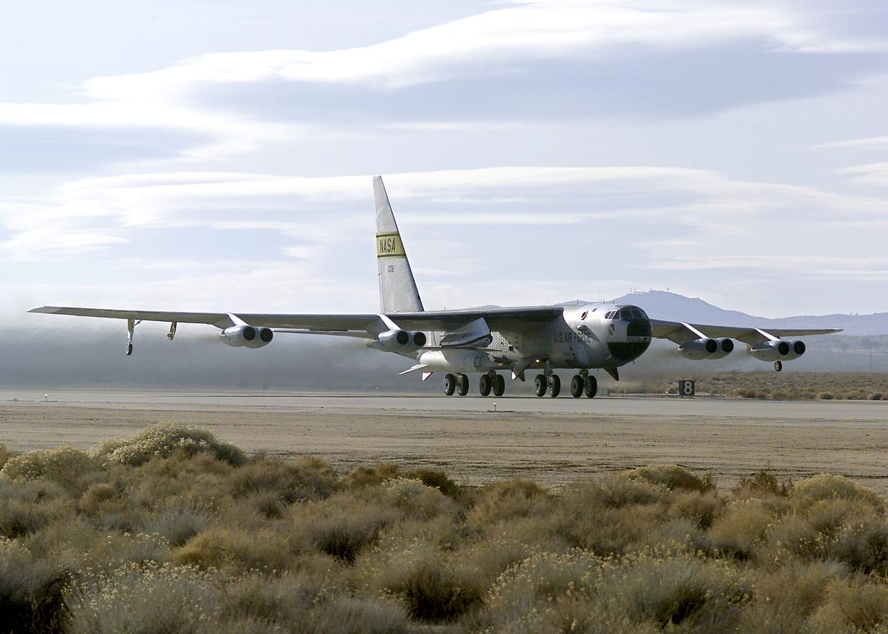
B-52 Launch Aircraft in Flight
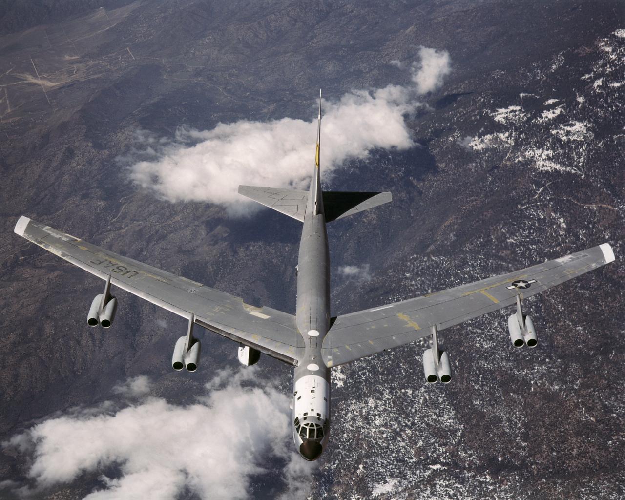
B-52 Launch Aircraft in Flight
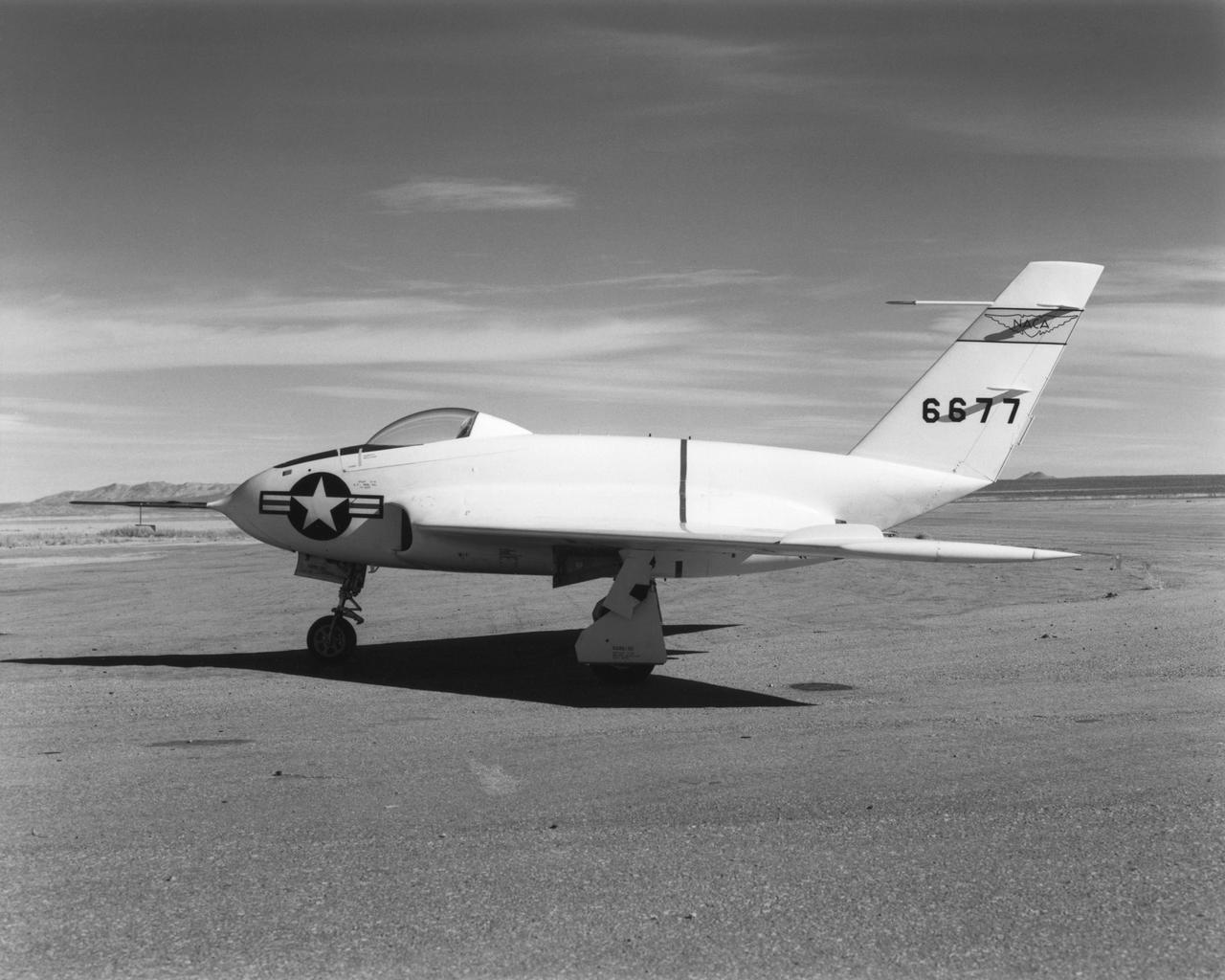
In this 1950 view of the left side of the NACA High-Speed Flight Research Station's X-4 research aircraft, the low swept wing and horizontal taillest design are seen. The X-4 Bantam, a single-place, low swept-wing, semi-tailless aircraft, was designed and built by Northrop Aircraft, Inc. It had no horizontal tail surfaces and its mission was to obtain in-flight data on the stability and control of semi-tailless aircraft at high subsonic speeds.
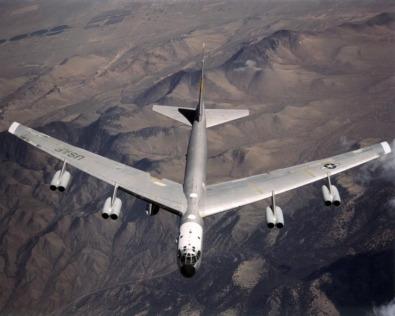
B-52 Launch Aircraft in Flight

Lake Mead supplies water for Arizona, California, Mexico, and other western states. On June 23, the water level fell to 1075 feet, a record low. In 2000, for comparison, the water level was at 1214 feet. A 15-year drought and increased demands for water are to blame for the critical status of the water supply. The difference in 15 years is seen in this pair of images of the western part of Lake Mead, acquired June 21, 2000 by Landsat 7, and June 21, 2015 by ASTER. The images cover an area of 22.5 x 28.5 km, and are located at 36.1 degrees north, 114.7 degrees west. http://photojournal.jpl.nasa.gov/catalog/PIA19731
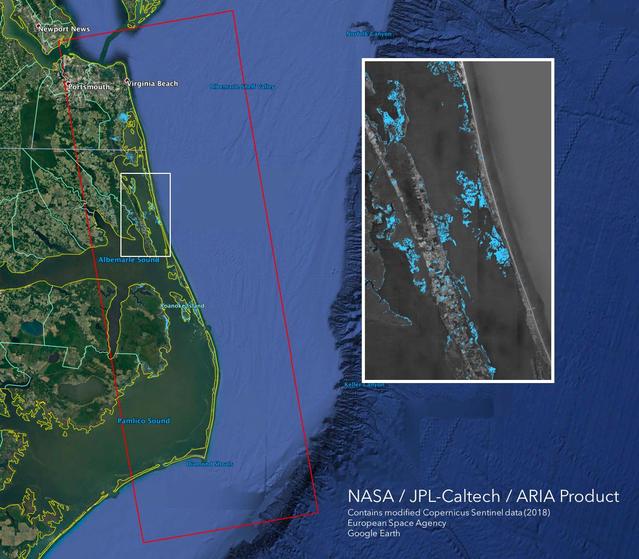
The Advanced Rapid Imaging and Analysis (ARIA) team at NASA's Jet Propulsion Laboratory in Pasadena, California, created this Flood Proxy Map depicting areas of the Carolinas that are likely flooded as a result of Hurricane Florence, shown by light blue pixels. The map is derived from synthetic aperture radar (SAR) images from the Copernicus Sentinel-1 satellites, operated by the European Space Agency (ESA). The images were taken before (September 09, 2018) and 36 hours after the hurricane's landfall (September 15, 2018 18:57 PM local time). The map covers an area of 53 miles x 152 miles (85 km x 245 km), indicated with the big red polygon. Each pixel measures about 33 yards x 33 yards (30 m x 30 m). Media reports provided anecdotal preliminary validation. This flood proxy map should be used as guidance to identify areas that are likely flooded and may be less reliable over urban and vegetated areas. https://photojournal.jpl.nasa.gov/catalog/PIA22704

STS059-S-086 (18 April 1994) --- This is a three-frequency false-color image of Flevoland, the Netherlands, centered at 52.4 degrees north latitude, and 5.4 degrees east longitude. This image was acquired by the Spaceborne Imaging Radar-C and X-Band Synthetic Aperture Radar (SIR-C/X-SAR) aboard the Space Shuttle Endeavour on April 14, 1994. It was produced by combining data from the X-Band, C-Band and L-Band radar's. The area shown is approximately 25 by 28 kilometers (15 1/2 by 17 1/2 miles). Flevoland, which fills the lower two-thirds of the image, is a very flat area that is made up of reclaimed land that is used for agriculture and forestry. At the top of the image, across the canal from Flevoland, is an older forest shown in red; the city of Harderwijk is shown in white on the shore of the canal. At this time of the year, the agricultural fields are bare soil, and they show up in this images in blue. The changes in the brightness of the blue areas are equal to the changes in roughness. The dark blue areas are water and the small dots in the canal are boats. This SIR-C/X-SAR supersite is being used for both calibration and agricultural studies. Several soil and crop ground-truth studies will be conducted during the Shuttle flight. In addition, about 10 calibration devices and 10 corner reflectors have been deployed to calibrate and monitor the radar signal. One of these transponders can be seen as a bright star in the lower right quadrant of the image. This false-color image was made using L-Band total power in the red channel, C-Band total power in the green channel, and X-Band VV polarization in the blue channel. SIR-C/X-SAR is part of NASA's Mission to Planet Earth (MTPE). SIR-C/X-SAR radars illuminate Earth with microwaves allowing detailed observations at any time, regardless of weather or sunlight conditions. SIR-C/X-SAR uses three microwave wavelengths: L-Band (24 cm), C-Band (6 cm), and X-Band (3 cm). The multi-frequency data will be used by the international scientific community to better understand the global environment and how it is changing. The SIR-C/X-SAR data, complemented by aircraft and ground studies, will give scientists clearer insights into those environmental changes which are caused by nature and those changes which are induced by human activity. SIR-C was developed by NASA's Jet Propulsion Laboratory (JPL). X-SAR was developed by the Dornire and Alenia Spazio Companies for the German Space Agency, Deutsche Agentur fuer Raumfahrtangelegenheiten (DARA), and the Italian Space Agency, Agenzia Spaziale Italiana (ASI). JPL Photo ID: P-43941
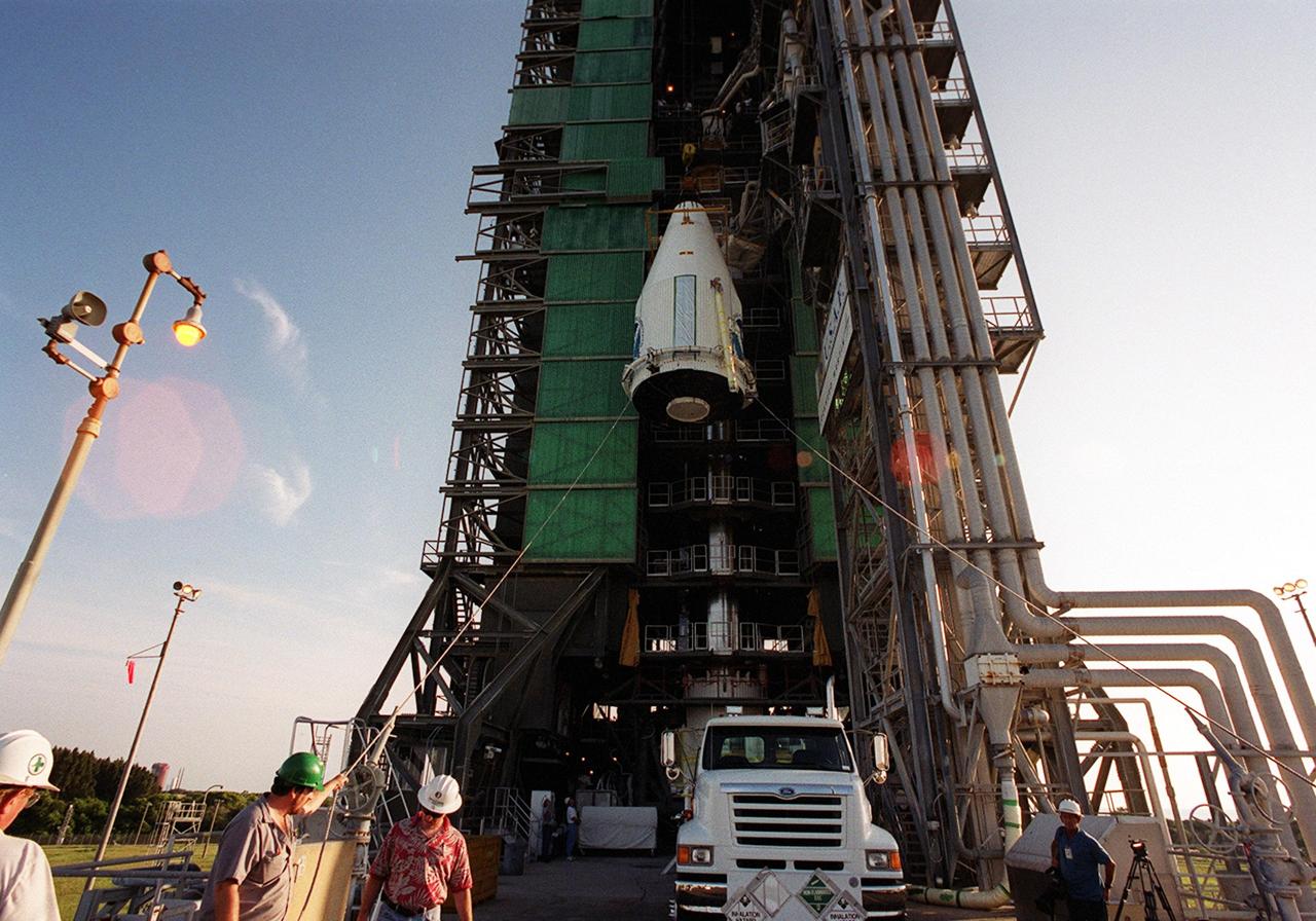
KENNEDY SPACE CENTER, Fla. -- The GOES-M satellite is lifted up the launch tower at Complex 36-A, Cape Canaveral Air Force Station. GOES-M is the last in the current series of advanced geostationary weather satellites in service. GOES-M has a new instrument not on earlier spacecraft, a Solar X-ray Imager, which can be used in forecasting space weather and the effects of solar storms. The satellite is scheduled to launch atop an Atlas rocket July 15
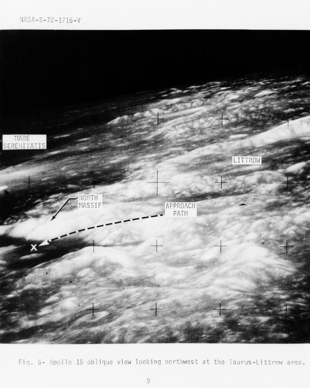
S72-01716 (July 1972) --- An oblique view of the Taurus-Littrow area on the lunar nearside, as photographed from the Apollo 15 spacecraft in lunar orbit. This is an enlarged view. The "X" marks the landing site of the scheduled Apollo 17 lunar landing mission. The overlay points out several features in the photograph. The coordinates of the Apollo 17 touchdown point are 30 degrees 44 minutes 58 seconds east longitude and 20 degrees 9 minutes 50 seconds north latitude.
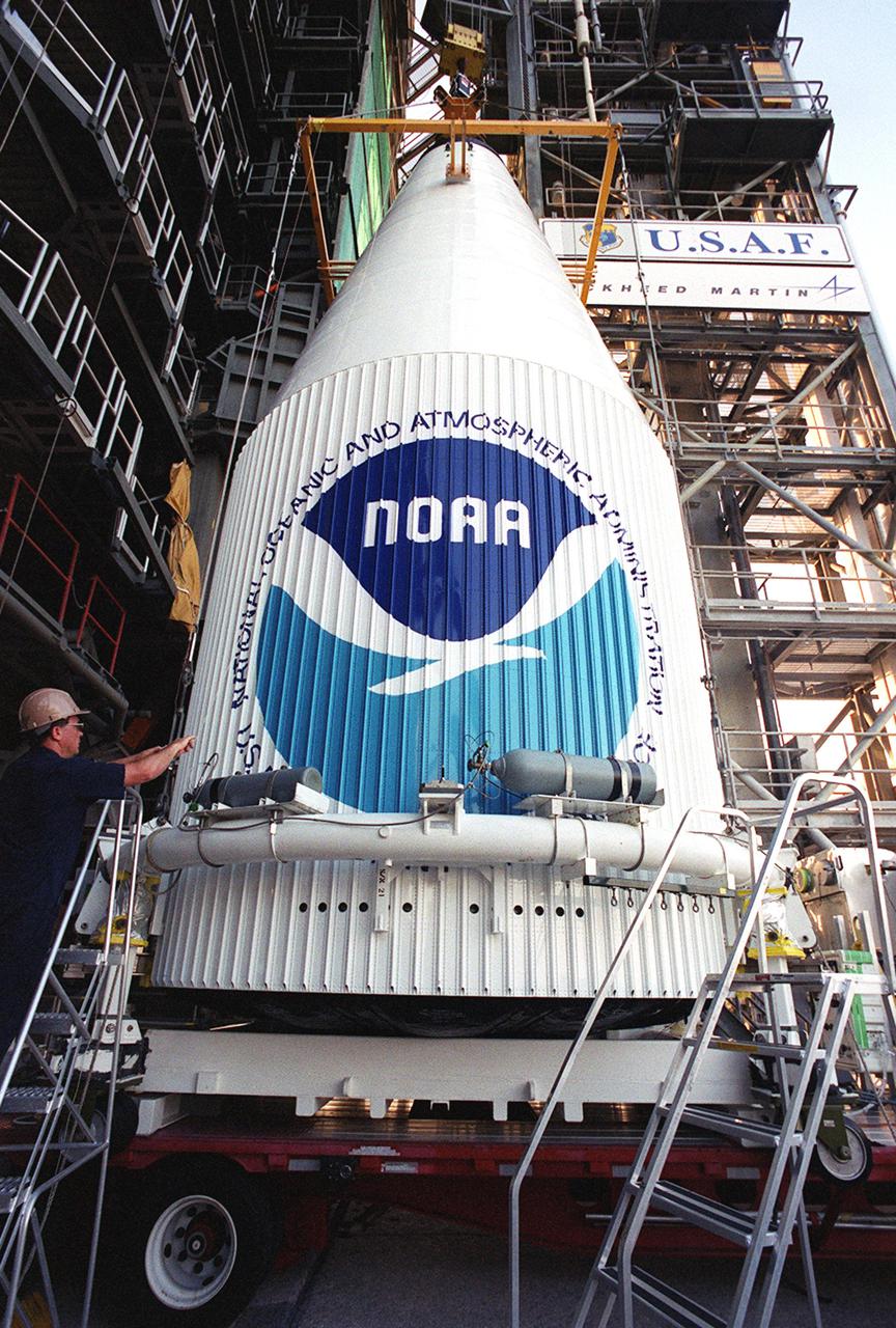
KENNEDY SPACE CENTER, Fla. -- The GOES-M satellite arrives at Complex 36-A, Cape Canaveral Air Force Station. GOES-M is the last in the current series of advanced geostationary weather satellites in service. GOES-M has a new instrument not on earlier spacecraft, a Solar X-ray Imager, which can be used in forecasting space weather and the effects of solar storms. The satellite is scheduled to launch atop an Atlas rocket July 15
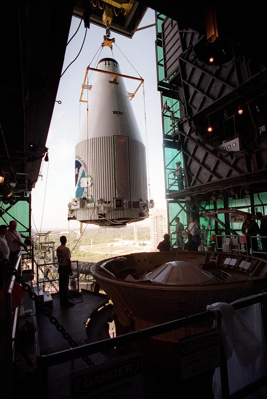
KENNEDY SPACE CENTER, Fla. -- The GOES-M satellite is moved toward the Atlas rocket in the launch tower at Complex 36-A, Cape Canaveral Air Force Station. GOES-M is the last in the current series of advanced geostationary weather satellites in service. GOES-M has a new instrument not on earlier spacecraft, a Solar X-ray Imager, which can be used in forecasting space weather and the effects of solar storms. The satellite is scheduled to launch atop an Atlas rocket July 15.