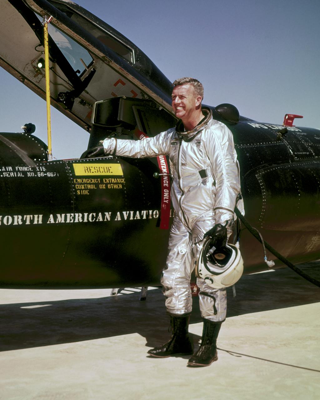
Joseph A. Walker was a Chief Research Pilot at the NASA Dryden Flight Research Center during the mid-1960s. He joined the NACA in March 1945, and served as project pilot at the Edwards flight research facility on such pioneering research projects as the D-558-1, D-558-2, X-1, X-3, X-4, X-5, and the X-15. He also flew programs involving the F-100, F-101, F-102, F-104, and the B-47. Walker made the first NASA X-15 flight on March 25, 1960. He flew the research aircraft 24 times and achieved its fastest speed and highest altitude. He attained a speed of 4,104 mph (Mach 5.92) during a flight on June 27, 1962, and reached an altitude of 354,300 feet on August 22, 1963 (his last X-15 flight). He was the first man to pilot the Lunar Landing Research Vehicle (LLRV) that was used to develop piloting and operational techniques for lunar landings. Walker was born February 20, 1921, in Washington, Pa. He lived there until graduating from Washington and Jefferson College in 1942, with a B.A. degree in Physics. During World War II he flew P-38 fighters for the Air Force, earning the Distinguished Flying Cross and the Air Medal with Seven Oak Clusters. Walker was the recipient of many awards during his 21 years as a research pilot. These include the 1961 Robert J. Collier Trophy, 1961 Harmon International Trophy for Aviators, the 1961 Kincheloe Award and 1961 Octave Chanute Award. He received an honorary Doctor of Aeronautical Sciences degree from his alma mater in June of 1962. Walker was named Pilot of the Year in 1963 by the National Pilots Association. He was a charter member of the Society of Experimental Test Pilots, and one of the first to be designated a Fellow. He was fatally injured on June 8, 1966, in a mid-air collision between an F-104 he was piloting and the XB-70.
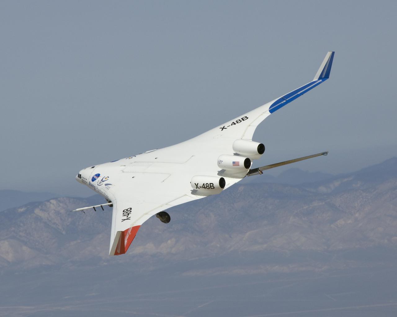
The X-48B Blended Wing Body research aircraft banks smartly in this Block 2 flight phase image.
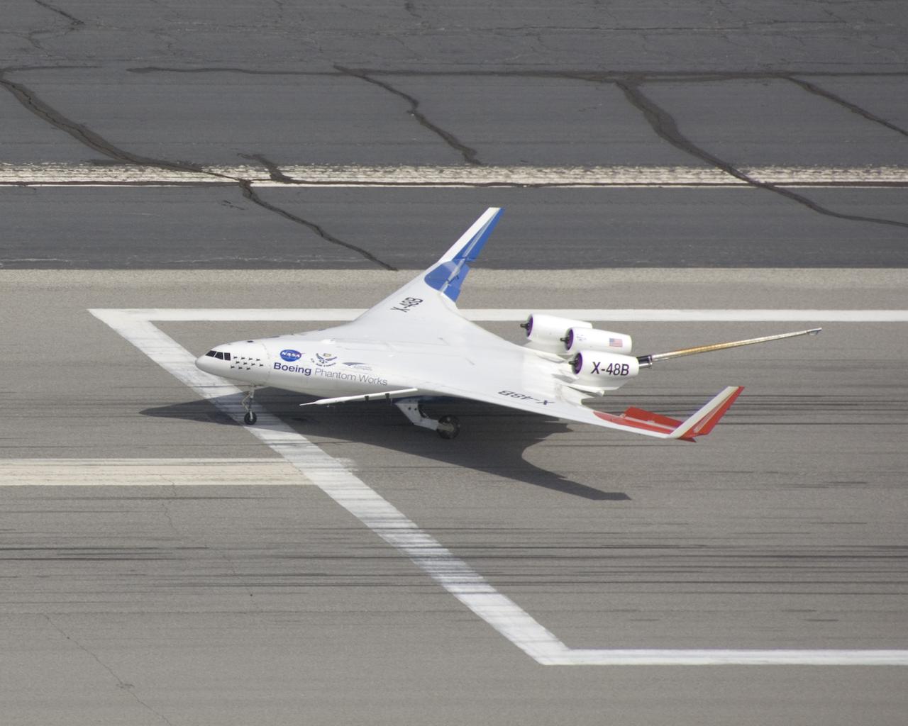
Making a nice landing, the X-48B Blended Wing Body research aircraft team ends another successful Block 2 flight.
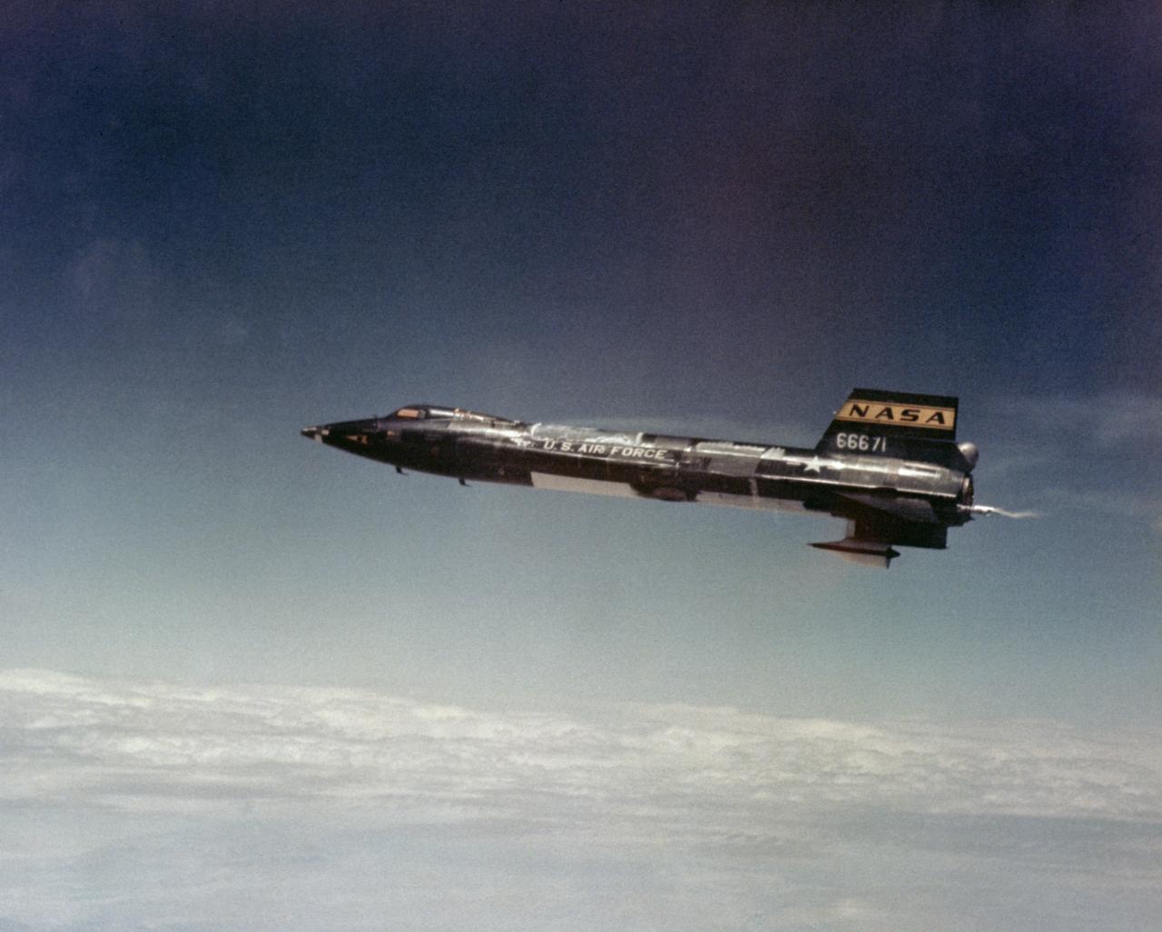
X-15A-2 in flight. First flight wih dummy ramjet attached. Flt. 2-51-92, Pete Knight-pilot. 8 May 67
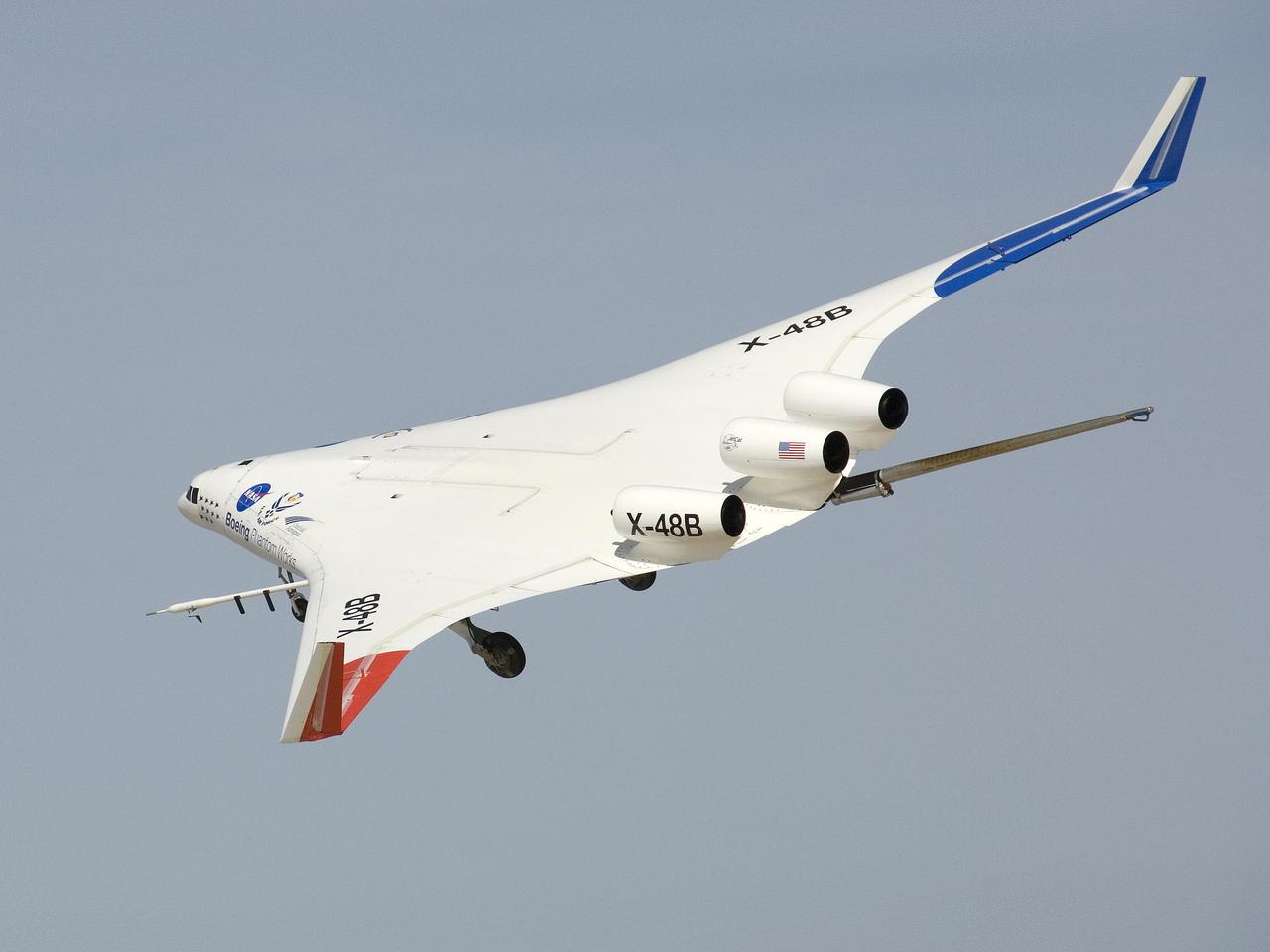
The X-48B Blended Wing Body research aircraft banked smartly in this Block 2 flight phase image.
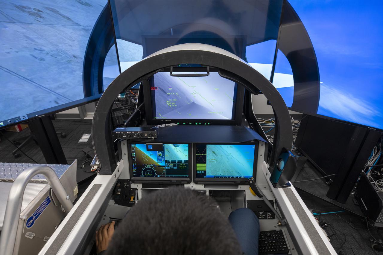
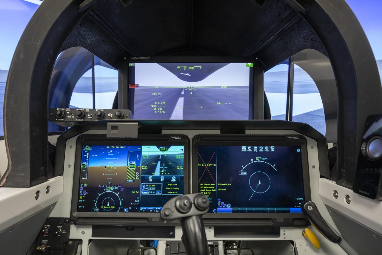
This image shows a close up of the cockpit view of the eXternal Vision System that will be placed in the X-59. Instead of a front facing window, the pilot will use these monitors for forward facing visibility. Lockheed Martin Photography By Garry Tice 1011 Lockheed Way, Palmdale, Ca. 93599 Event: X-59 SIL Round 2 Date: 6/10/2021
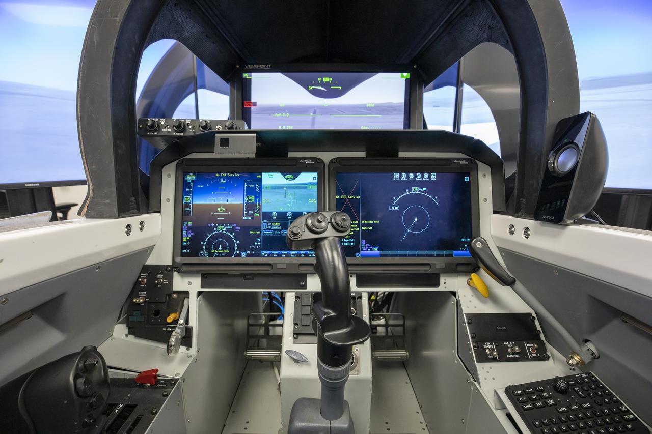
This image shows a close up of the cockpit view of the eXternal Vision System that will be placed in the X-59. Instead of a front facing window, the pilot will use these monitors for forward facing visibility. Lockheed Martin Photography By Garry Tice 1011 Lockheed Way, Palmdale, Ca. 93599 Event: X-59 SIL Round 2 Date: 6/10/2021
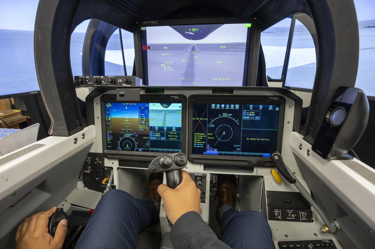
This image shows a close up of the cockpit view of the eXternal Vision System that will be placed in the X-59. Instead of a front facing window, the pilot will use these monitors for forward facing visibility. Lockheed Martin Photography By Garry Tice 1011 Lockheed Way, Palmdale, Ca. 93599 Event: X-59 SIL Round 2 Date: 6/10/2021
This image shows a close up of the cockpit view of the eXternal Vision System that will be placed in the X-59. Instead of a front facing window, the pilot will use these monitors for forward facing visibility. Lockheed Martin Photography By Garry Tice 1011 Lockheed Way, Palmdale, Ca. 93599 Event: X-59 SIL Round 2 Date: 6/10/2021
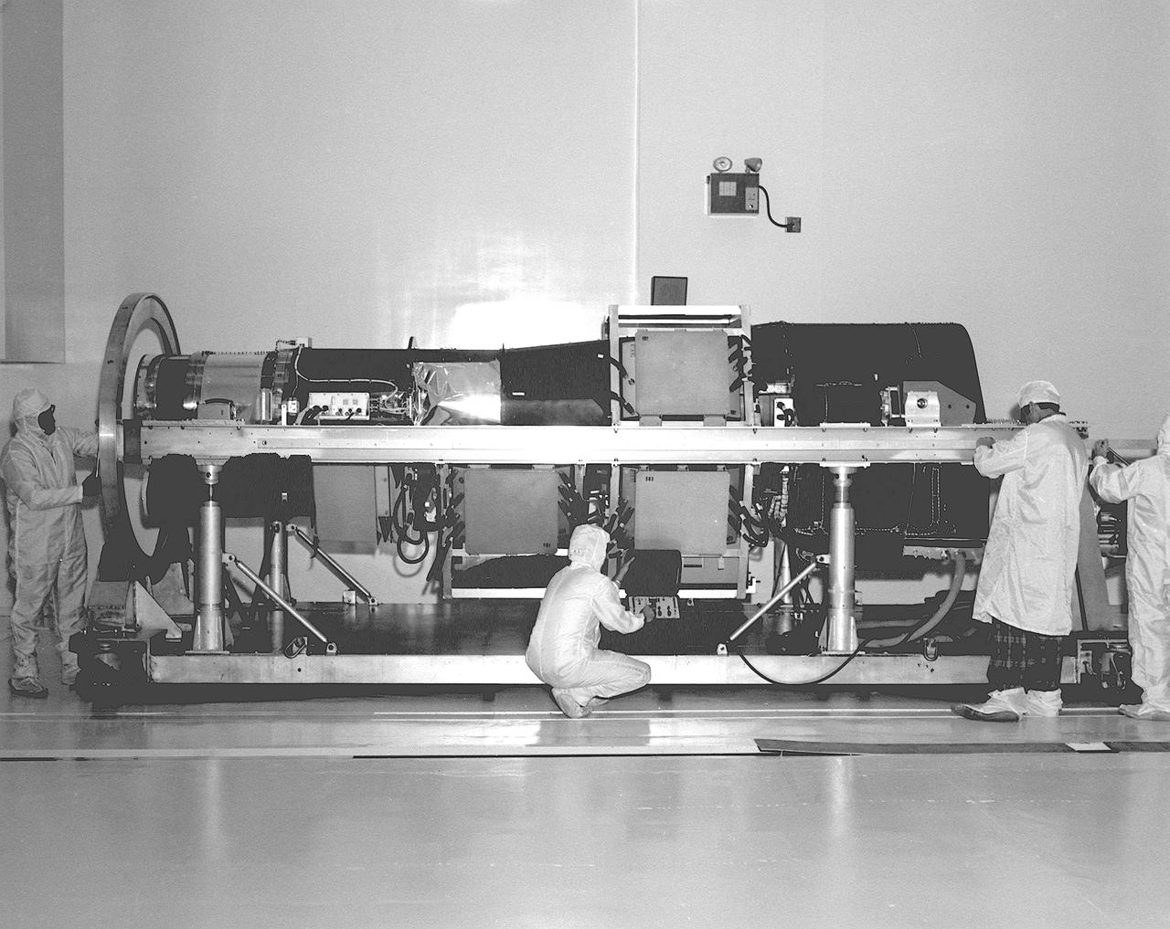
This photograph is of the High Energy Astronomy Observatory (HEAO)-2 telescope being checked by engineers in the X-Ray Calibration Facility at the Marshall Space Flight Center (MSFC). The MSFC was heavily engaged in the technical and scientific aspects, testing and calibration, of the HEAO-2 telescope. The HEAO-2 was the first imaging and largest x-ray telescope built to date. The X-Ray Calibration Facility was built in 1976 for testing MSFC's HEAO-2. The facility is the world's largest, most advanced laboratory for simulating x-ray emissions from distant celestial objects. It produced a space-like environment in which components related to x-ray telescope imaging are tested and the quality of their performance in space is predicted. The original facility contained a 1,000-foot long by 3-foot diameter vacuum tube (for the x-ray path) cornecting an x-ray generator and an instrument test chamber. Recently, the facility was upgraded to evaluate the optical elements of NASA's Hubble Space Telescope, Chandra X-Ray Observatory and Compton Gamma-Ray Observatory.
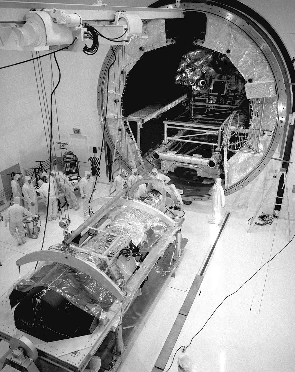
This photograph is of the High Energy Astronomy Observatory (HEAO)-2 telescope being evaluated by engineers in the clean room of the X-Ray Calibration Facility at the Marshall Space Flight Center (MSFC). The MSFC was heavily engaged in the technical and scientific aspects, testing and calibration, of the HEAO-2 telescope The HEAO-2 was the first imaging and largest x-ray telescope built to date. The X-Ray Calibration Facility was built in 1976 for testing MSFC's HEAO-2. The facility is the world's largest, most advanced laboratory for simulating x-ray emissions from distant celestial objects. It produced a space-like environment in which components related to x-ray telescope imaging are tested and the quality of their performance in space is predicted. The original facility contained a 1,000-foot long by 3-foot diameter vacuum tube (for the x-ray path) cornecting an x-ray generator and an instrument test chamber. Recently, the facility was upgraded to evaluate the optical elements of NASA's Hubble Space Telescope, Chandra X-Ray Observatory and Compton Gamma-Ray Observatory.
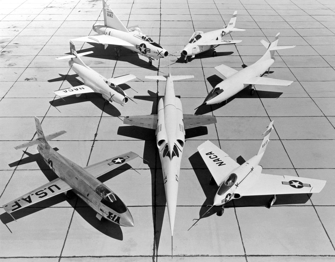
A 1953 photo of some of the research aircraft at the NACA High-Speed Flight Research Station (now known as the the Dryden Flight Research Center). The photo shows the X-3 (center) and, clockwise from left: X-1A (Air Force serial number 48-1384), the third D-558-1 (NACA tail number 142), XF-92A, X-5, D-558-2, and X-4.
NASA research pilot Jack McKay was injured in a crash landing of the X-15 #2 on November 9, 1962. Following the launch from the B-52 to begin flight 2-31-52, he started the X-15's rocket engine, only to discover that it produced just 30 percent of its maximum thrust. He had to make a high-speed emergency landing on Mud Lake, NV, without flaps but with a significant amount of fuel still in the aircraft. As the X-15 slid across the lakebed, the left skid collapsed; the aircraft turned sideways and flipped onto its back. McKay suffered back injuries but was eventually able to resume X-15 pilot duties, making 22 more flights. The X-15 was sent back to North American Aviation and rebuilt into the X-15A-2.
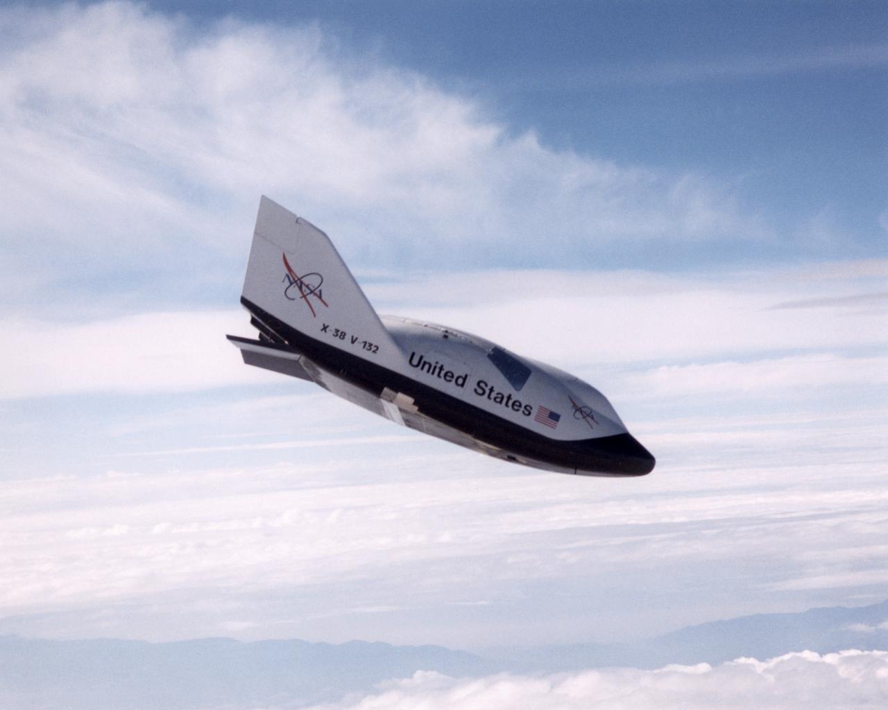
The X-38, a research vehicle built to help develop technology for an emergency Crew Return Vehicle (CRV), descends under its steerable parachute during a July 1999 test flight at the Dryden Flight Research Center, Edwards, California. It was the fourth free flight of the test vehicles in the X-38 program, and the second free flight test of Vehicle 132 or Ship 2. The goal of this flight was to release the vehicle from a higher altitude -- 31,500 feet -- and to fly the vehicle longer -- 31 seconds -- than any previous X-38 vehicle had yet flown. The project team also conducted aerodynamic verification maneuvers and checked improvements made to the drogue parachute.
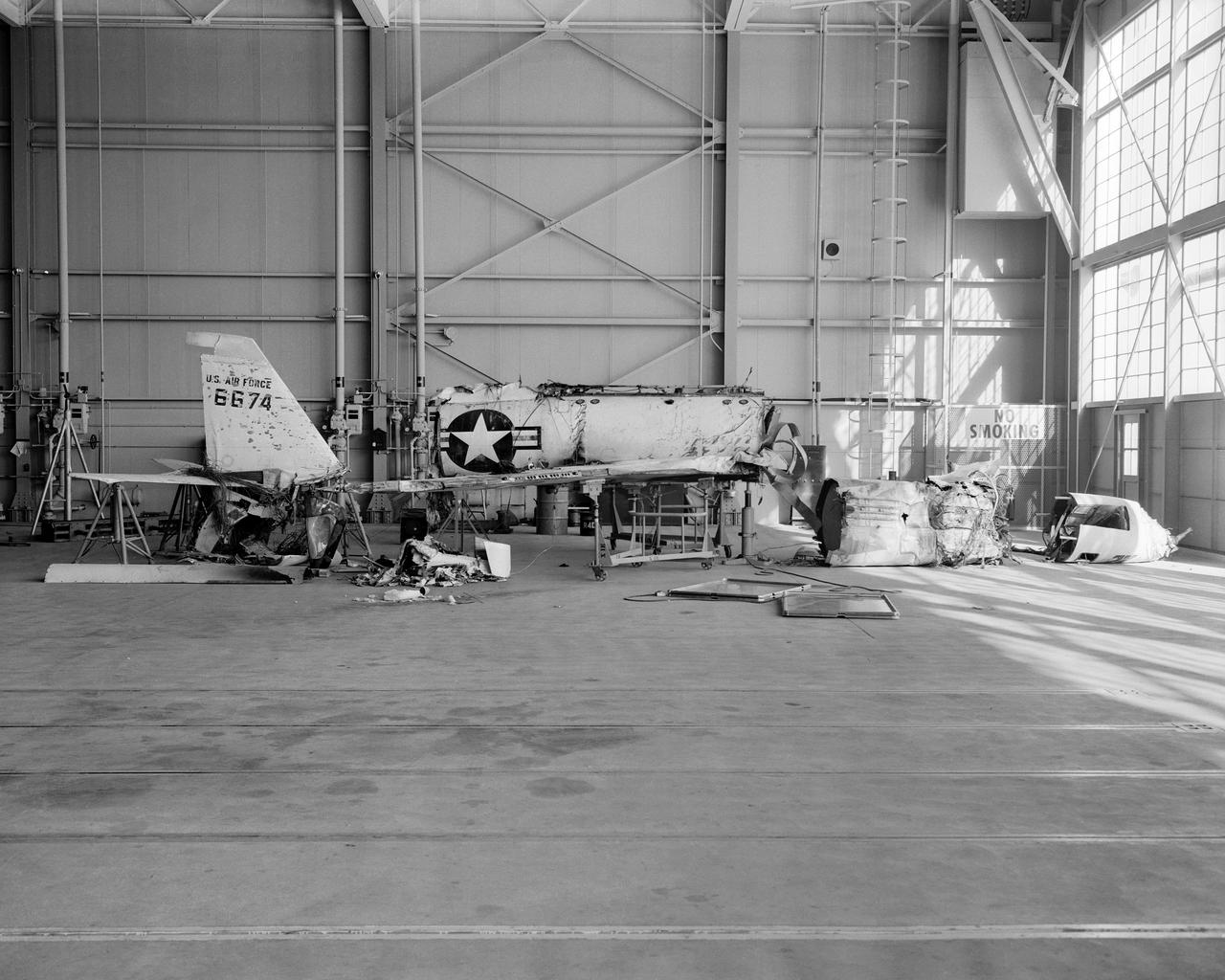
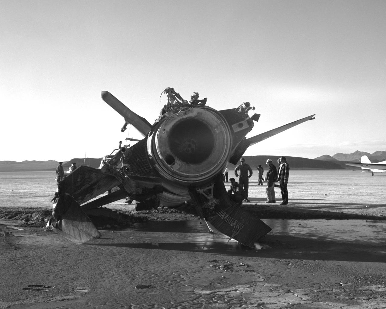
The X-2, initially an Air Force program, was scheduled to be transferred to the civilian National Advisory Committee for Aeronautics (NACA) for scientific research. The Air Force delayed turning the aircraft over to the NACA in the hope of attaining Mach 3 in the airplane. The service requested and received a two-month extension to qualify another Air Force test pilot, Capt. Miburn "Mel" Apt, in the X-2 and attempt to exceed Mach 3. After several ground briefings in the simulator, Apt (with no previous rocket plane experience) made his flight on 27 September 1956. Apt raced away from the B-50 under full power, quickly outdistancing the F-100 chase planes. At high altitude, he nosed over, accelerating rapidly. The X-2 reached Mach 3.2 (2,094 mph) at 65,000 feet. Apt became the first man to fly more than three times the speed of sound. Still above Mach 3, he began an abrupt turn back to Edwards. This maneuver proved fatal as the X-2 began a series of diverging rolls and tumbled out of control. Apt tried to regain control of the aircraft. Unable to do so, Apt separated the escape capsule. Too late, he attempted to bail out and was killed when the capsule impacted on the Edwards bombing range. The rest of the X-2 crashed five miles away. The wreckage of the X-2 rocket plane was later taken to NACA's High Speed Flight Station for analysis following the crash.

This image of the suspected Black Hole, Cygnus X-1, was the first object seen by the High Energy Astronomy Observatory (HEAO)-2/Einstein Observatory. According to the theories to date, one concept of a black hole is a star, perhaps 10 times more massive than the Sun, that has entered the last stages of stelar evolution. There is an explosion triggered by nuclear reactions after which the star's outer shell of lighter elements and gases is blown away into space and the heavier elements in the stellar core begin to collapse upon themselves. Once this collapse begins, the inexorable force of gravity continues to compact the material until it becomes so dense it is squeezed into a mere point and nothing can escape from its extreme gravitational field, not even light. The HEAO-2, the first imaging and largest x-ray telescope built to date, was capable of producing actual photographs of x-ray objects. Shortly after launch, the HEAO-2 was nicknamed the Einstein Observatory by its scientific experimenters in honor of the centernial of the birth of Albert Einstein, whose concepts of relativity and gravitation have influenced much of modern astrophysics, particularly x-ray astronomy.
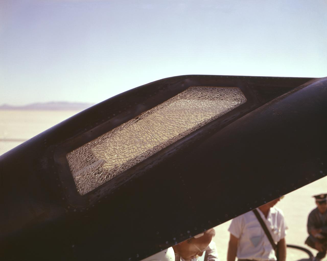
Cracked canopy glass on right side of X-15 #2 after flt. 2-21-37 on Nov. 9 1961. Robert White-pilot. First flight to mach 6.
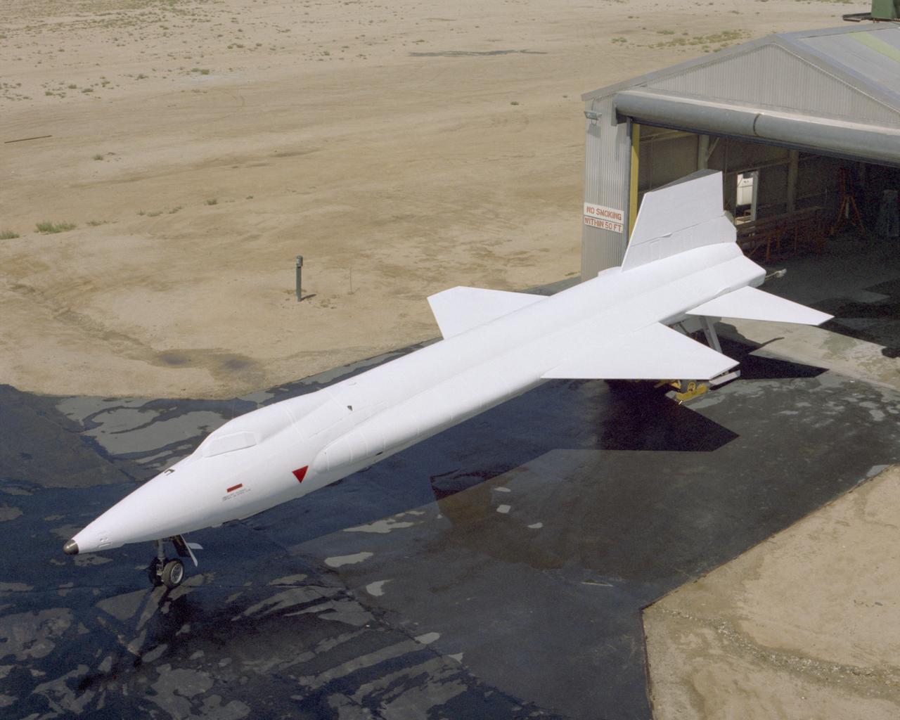
X-15A-2 is rolled out of the paint shop after having the full scale ablative applied. In June 1967, the X-15A-2 rocket-powered research aircraft received a full-scale ablative coating to protect the craft from the high temperatures associated with hypersonic flight (above Mach 5). This pink eraser-like substance, applied to the X-15A-2 aircraft (56-6671), was then covered with a white sealant coat before flight. This coating would help the #2 aircraft reach the record speed of 4,520 mph (Mach 6.7).
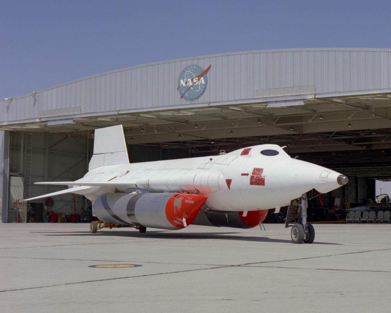
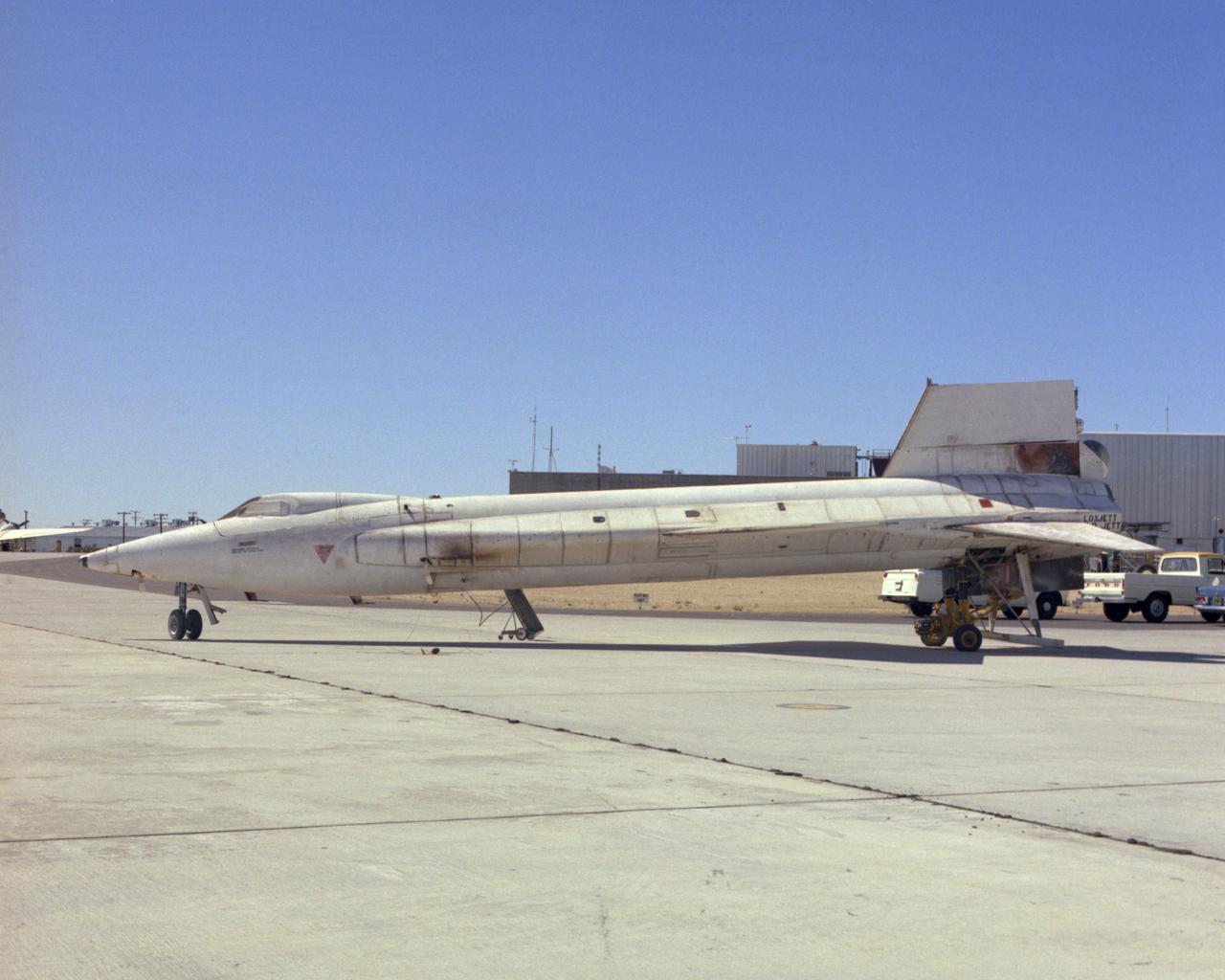
X-15A-2 with full scale ablative and external tanks installed parked in front of hangar. In June 1967, the X-15A-2 rocket-powered research aircraft received a full-scale ablative coating to protect the craft from the high temperatures associated with hypersonic flight (above Mach 5). This pink eraser-like substance, applied to the X-15A-2 aircraft (56-6671), was then covered with a white sealant coat before flight. This coating would help the #2 aircraft reach the record speed of 4,520 mph (Mach 6.7).
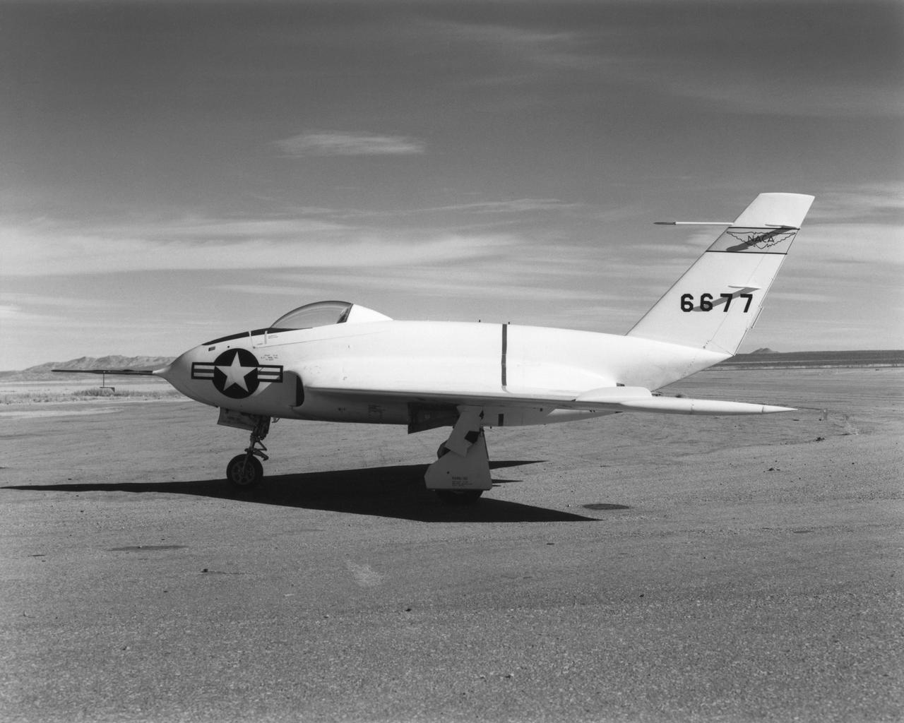
In this 1950 view of the left side of the NACA High-Speed Flight Research Station's X-4 research aircraft, the low swept wing and horizontal taillest design are seen. The X-4 Bantam, a single-place, low swept-wing, semi-tailless aircraft, was designed and built by Northrop Aircraft, Inc. It had no horizontal tail surfaces and its mission was to obtain in-flight data on the stability and control of semi-tailless aircraft at high subsonic speeds.

Southwestern US, with Las Vegas, NV in foreground, taken by X-15 Hycon HR-236 Camera during flt. 2-39-70 on June 27, 1965.
X-15A-2 post flight photo showing heat damage from Mach 6.7 flight on 3 Oct 67. Flt. 2-53-97; pilot-Pete Knight.
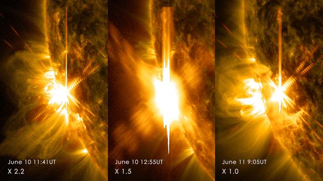
Three X-class flares erupted from the left side of the sun June 10-11, 2014. These images are from NASA's Solar Dynamics Observatory and show light in a blend of two ultraviolet wavelengths: 171 and 131 angstroms. The former is colorized in yellow; the latter, in red. Read more: <a href="http://1.usa.gov/1lneJ3p" rel="nofollow">1.usa.gov/1lneJ3p</a> Credit: NASA/SDO <b><a href="http://www.nasa.gov/audience/formedia/features/MP_Photo_Guidelines.html" rel="nofollow">NASA image use policy.</a></b> <b><a href="http://www.nasa.gov/centers/goddard/home/index.html" rel="nofollow">NASA Goddard Space Flight Center</a></b> enables NASA’s mission through four scientific endeavors: Earth Science, Heliophysics, Solar System Exploration, and Astrophysics. Goddard plays a leading role in NASA’s accomplishments by contributing compelling scientific knowledge to advance the Agency’s mission. <b>Follow us on <a href="http://twitter.com/NASAGoddardPix" rel="nofollow">Twitter</a></b> <b>Like us on <a href="http://www.facebook.com/pages/Greenbelt-MD/NASA-Goddard/395013845897?ref=tsd" rel="nofollow">Facebook</a></b> <b>Find us on <a href="http://instagram.com/nasagoddard?vm=grid" rel="nofollow">Instagram</a></b>

The Bell Aircraft Corporation X-1-2 aircraft on the ramp at NACA High Speed Flight Research Station located on the South Base of Muroc Army Air Field in 1947. The X-1-2 flew until October 23, 1951, completing 74 glide and powered flights with nine different pilots. The aircraft has white paint and the NACA tail band. The black Xs are reference markings for tracking purposes. They were widely used on NACA aircraft in the early 1950s.
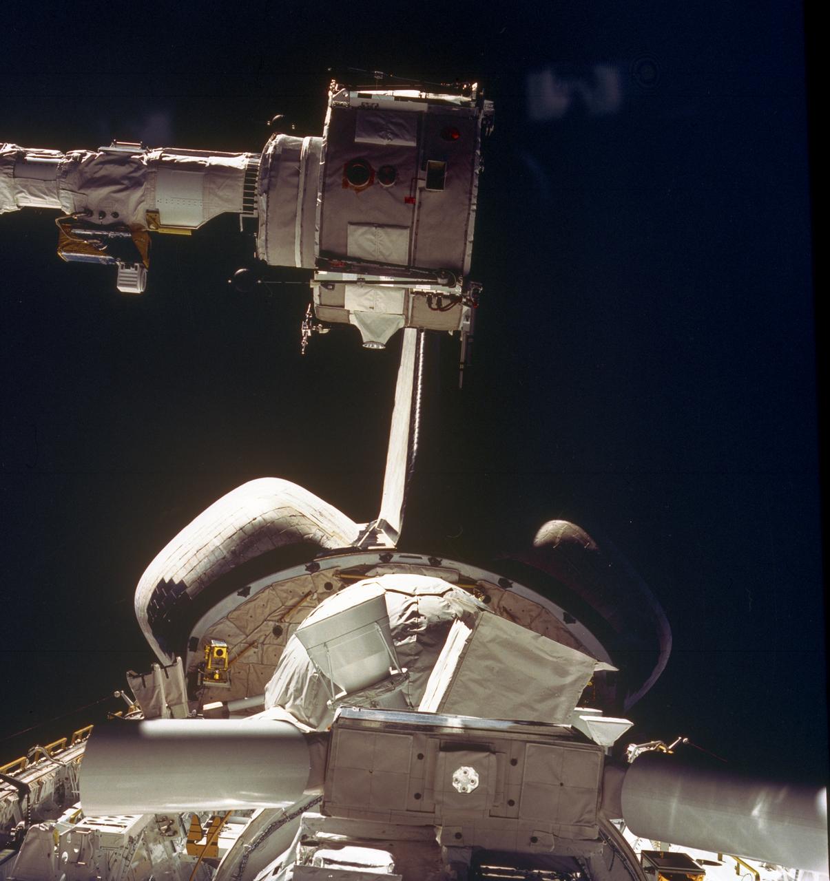
This STS-51F mission onboard Photograph shows some of the Spacelab-2 instruments in the cargo bay of the Orbiter Challenger. The Plasma Diagnostics Package (PDP). shown at the end of the Remote Manipulator System (RMS), used instruments on a subsatellite to study natural plasma processes, orbiter-induced plasma processes, and beam plasma physics. Fourteen instruments were mounted on the PDP for measurements of various plasma characteristics. The X-ray Telescope (XRT), is at the front. The goal of this investigation was to image and examine the X-ray emissions from clusters of galaxies in order to study the mechanisms that cause high-temperature emissions and to determine the weight of galactic clusters. The Small Helium-Cooled Infrared Telescope (IRT) is at the right behind the XRT. The objective of this investigation was to measure and map diffused and discrete infrared astronomical sources while evaluating the Space Shuttle as a platform for infrared astronomy. At the same time, a new large superfluid helium dewar system for cooling the telescope was evaluated. The egg-shaped Cosmic Ray Nuclei experiment (CRNE) is shown at the rear. This investigation was to study the composition of high-energy cosmic rays by using a large instrument exposed to space for a considerable period of time. Spacelab-2 (STS-51F, 19th Shuttle mission) was launched aboard the Space Shuttle Orbiter Challenger on July 29, 1985.
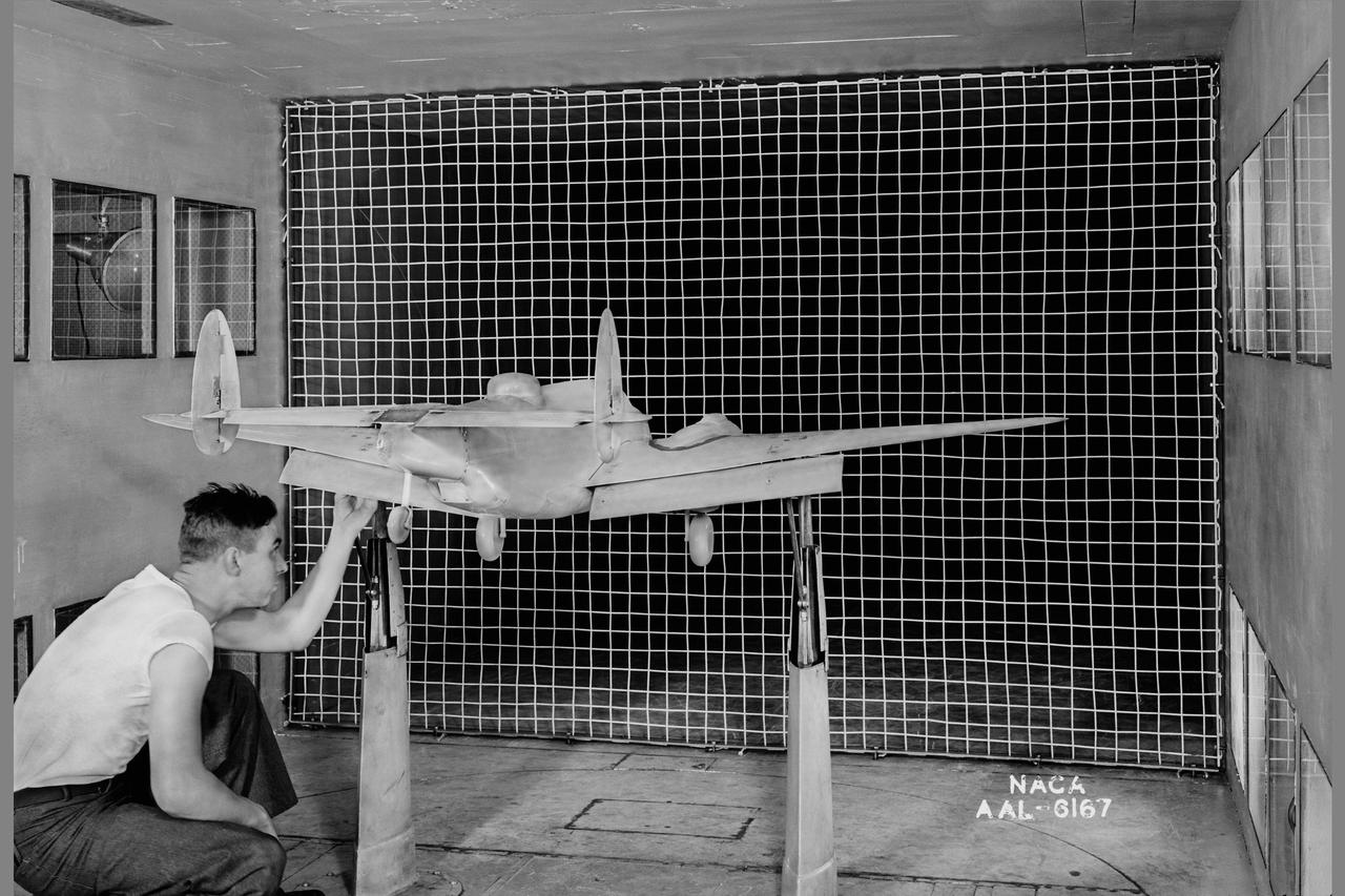
PV-1 model; rear view with 2 1/2' x 2 1/2' trubulene net mount in the 7x10ft w.t. at Ames Research Center
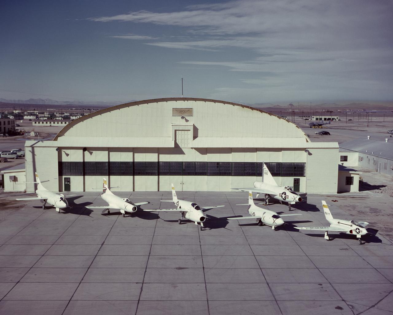
NACA X-Planes on South Base ramp. Northrop X-4, Bell X-1, Bell X-5, Douglas D-558-1, Douglas D-558-2. Back row Convair XF-92A. March 30, 1952

This is an x-ray image of the Crab Nebula taken with the High Energy Astronomy Observatory (HEAO)-2/Einstein Observatory. The image is demonstrated by a pulsar, which appears as a bright point due to its pulsed x-ray emissions. The strongest region of diffused emissions comes from just northwest of the pulsar, and corresponds closely to the region of brightest visible-light emission. The HEAO-2, the first imaging and largest x-ray telescope built to date, was capable of producing actual photographs of x-ray objects. Shortly after launch, the HEAO-2 was nicknamed the Einstein Observatory by its scientific experimenters in honor of the centernial of the birth of Albert Einstein, whose concepts of relativity and gravitation have influenced much of modern astrophysics, particularly x-ray astronomy. The HEAO-2, designed and developed by TRW, Inc. under the project management of the Marshall Space Flight Center, was launched aboard an Atlas/Centaur launch vehicle on November 13, 1978.

This x-ray photograph of the Supernova remnant Cassiopeia A, taken with the High Energy Astronomy Observatory (HEAO) 2/Einstein Observatory, shows that the regions with fast moving knots of material in the expanding shell are bright and clear. A faint x-ray halo, just outside the bright shell, is interpreted as a shock wave moving ahead of the expanding debris. The HEAO-2, the first imaging and largest x-ray telescope built to date, was capable of producing actual photographs of x-ray objects. Shortly after launch, the HEAO-2 was nicknamed the Einstein Observatory by its scientific experimenters in honor of the centernial of the birth of Albert Einstein, whose concepts of relativity and gravitation have influenced much of modern astrophysics, particularly x-ray astronomy. The HEAO-2, designed and developed by TRW, Inc. under the project management of the Marshall Space Flight Center, was launched aboard an Atlas/Centaur launch vehicle on November 13, 1978.
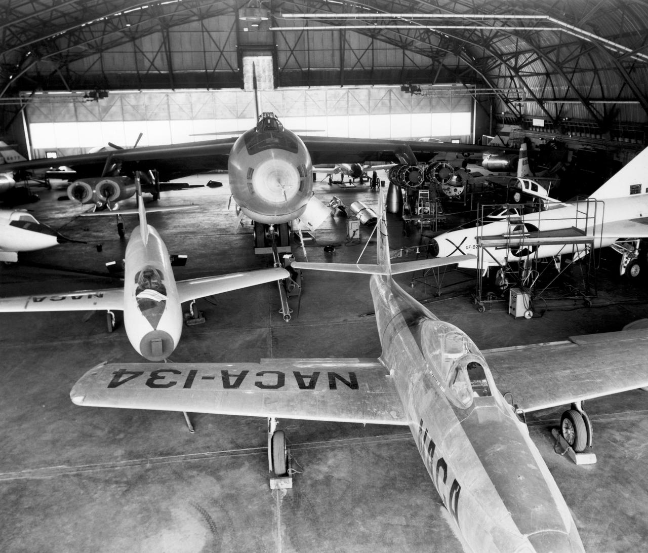
In the center foreground of this 1953 hangar photo is the YF-84A (NACA 134/Air Force 45-59490) used for vortex generator research. It arrived on November 28, 1949, and departed on April 21, 1954. Beside it is the third D-558-1 aircraft (NACA 142/Navy 37972). This aircraft was used for a total of 78 transonic research flights from April 1949 to June 1954. It replaced the second D-558-1, lost in the crash which killed Howard Lilly. Just visible on the left edge is the nose of the first D-558-2 (NACA 143/Navy 37973). Douglas turned the aircraft over to NACA on August 31, 1951, after the contractor had completed its initial test flights. NACA only made a single flight with the aircraft, on September 17, 1956, before the program was cancelled. In the center of the photo is the B-47A (NACA 150/Air Force 49-1900). The B-47 jet bomber, with its thin, swept-back wings, and six podded engines, represented the state of the art in aircraft design in the early 1950s. The aircraft undertook a number of research activities between May 1953 and its 78th and final research flight on November 22, 1957. The tests showed that the aircraft had a buffeting problem at speeds above Mach 0.8. Among the pilots who flew the B-47 were later X-15 pilots Joe Walker, A. Scott Crossfield, John B. McKay, and Neil A. Armstrong. On the right side of the B-47 is NACA's X-1 (Air Force 46-063). The second XS-1 aircraft built, it was fitted with a thicker wing than that on the first aircraft, which had exceeded Mach 1 on October 14, 1947. Flight research by NACA pilots indicated that this thicker wing produced 30 percent more drag at transonic speeds compared to the thinner wing on the first X-1. After a final flight on October 23, 1951, the aircraft was grounded due to the possibility of fatigue failure of the nitrogen spheres used to pressurize the fuel tanks. At the time of this photo, in 1953, the aircraft was in storage. In 1955, the aircraft was extensively modified, becoming the X-1E. In front o

Both of the High Energy Astronomy Observatory (HEAO) 2/Einstein Observatory imaging devices were used to observe the Great Nebula in Andromeda, M31. This image is a wide field x-ray view of the center region of M31 by the HEAO-2's Imaging Proportional Counter. The HEAO-2, the first imaging and largest x-ray telescope built to date, was capable of producing actual photographs of x-ray objects. Shortly after launch, the HEAO-2 was nicknamed the Einstein Observatory by its scientific experimenters in honor of the centernial of the birth of Albert Einstein, whose concepts of relativity and gravitation have influenced much of modern astrophysics, particularly x-ray astronomy. The HEAO-2, designed and developed by TRW, Inc. under the project management of the Marshall Space Flight Center, was launched aboard an Atlas/Centaur launch vehicle on November 13, 1978.
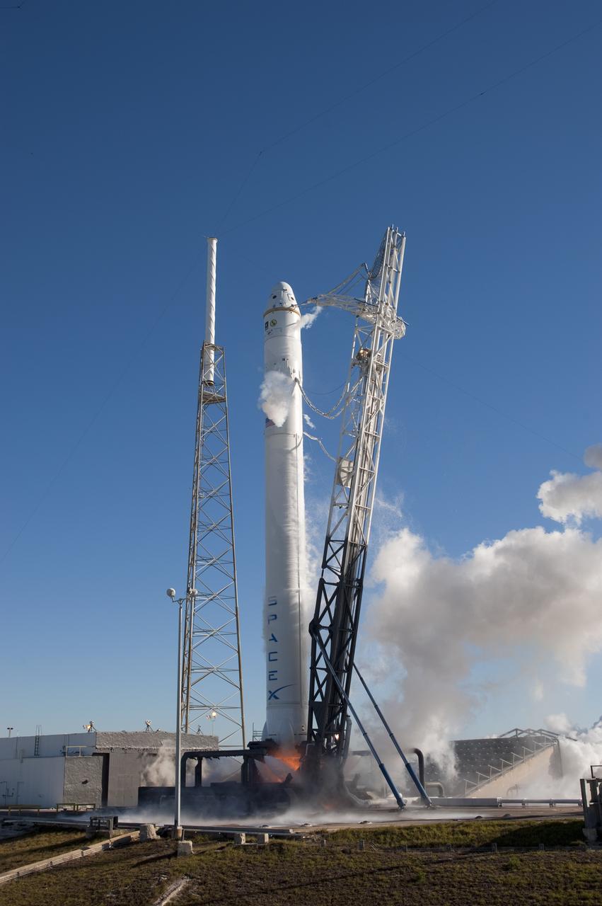
SPACE X FALCON 9 COTS-1 TEST FIRE - DAY 2
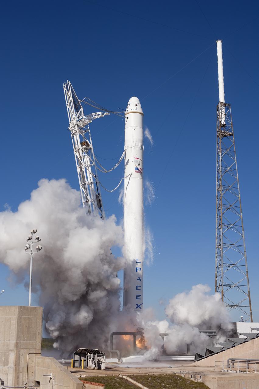
SPACE X FALCON 9 COTS-1 TEST FIRE - DAY 2
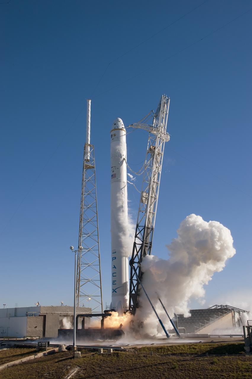
SPACE X FALCON 9 COTS-1 TEST FIRE - DAY 2
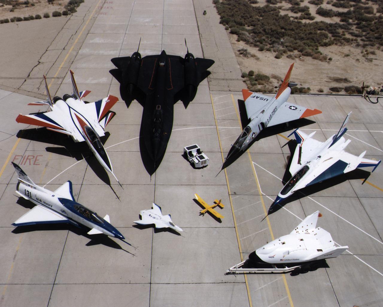
A collection of NASA's research aircraft on the ramp at the Dryden Flight Research Center in July 1997: X-31, F-15 ACTIVE, SR-71, F-106, F-16XL Ship #2, X-38, Radio Controlled Mothership and X-36.
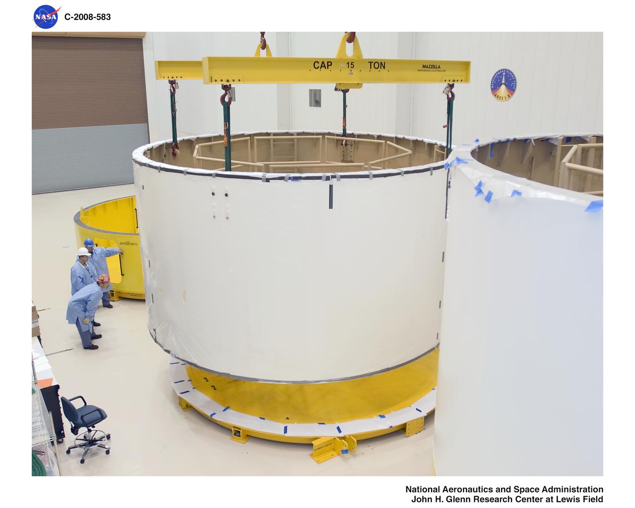
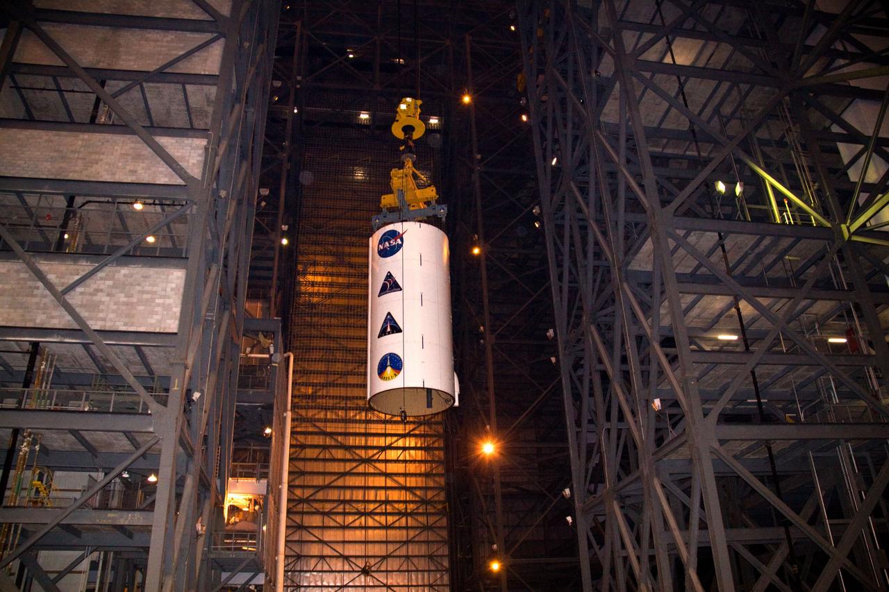
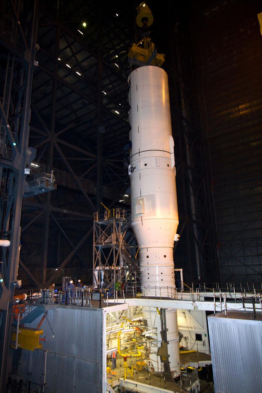
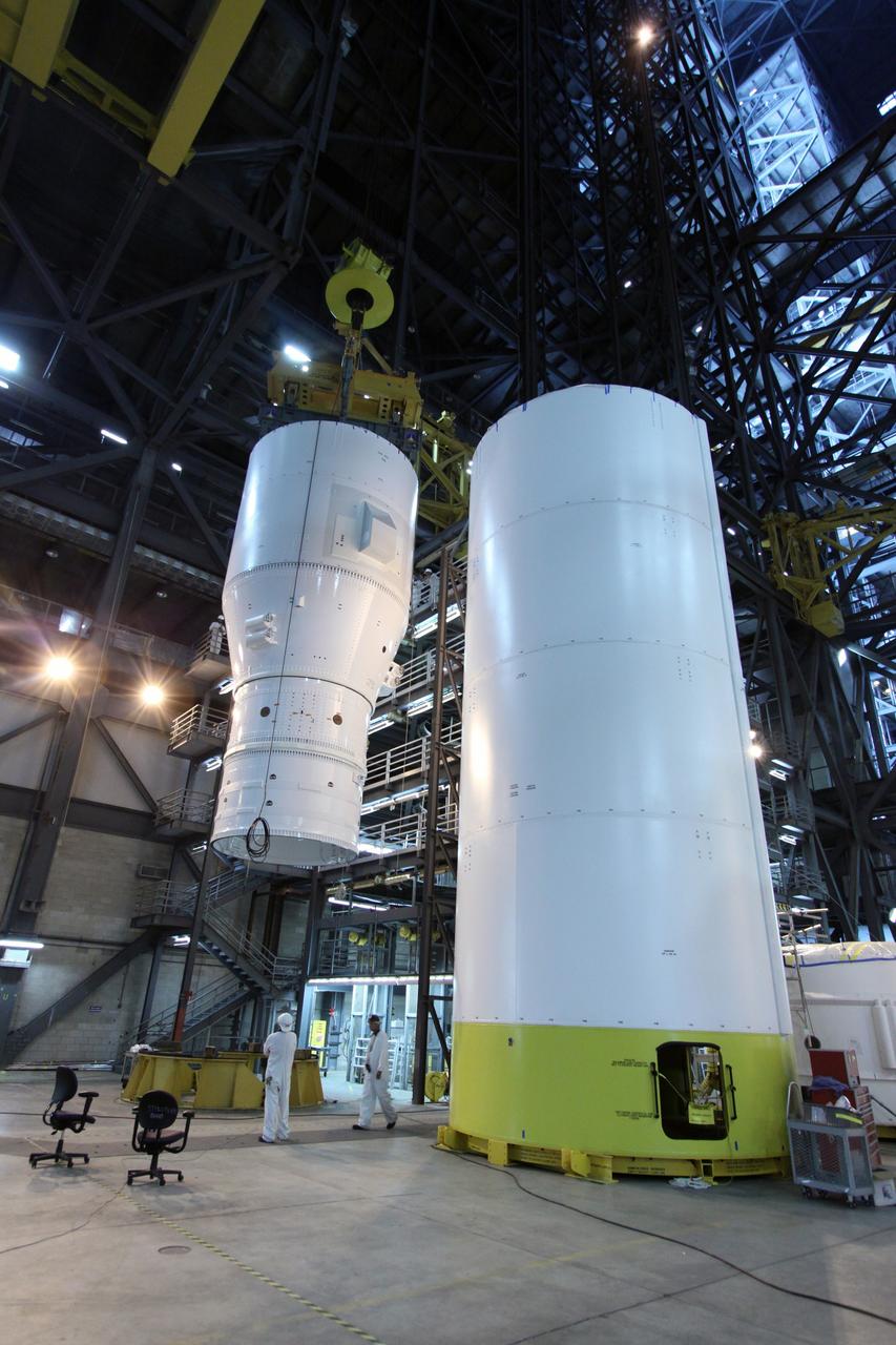
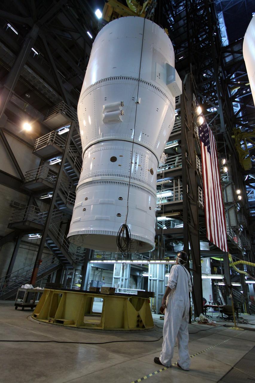
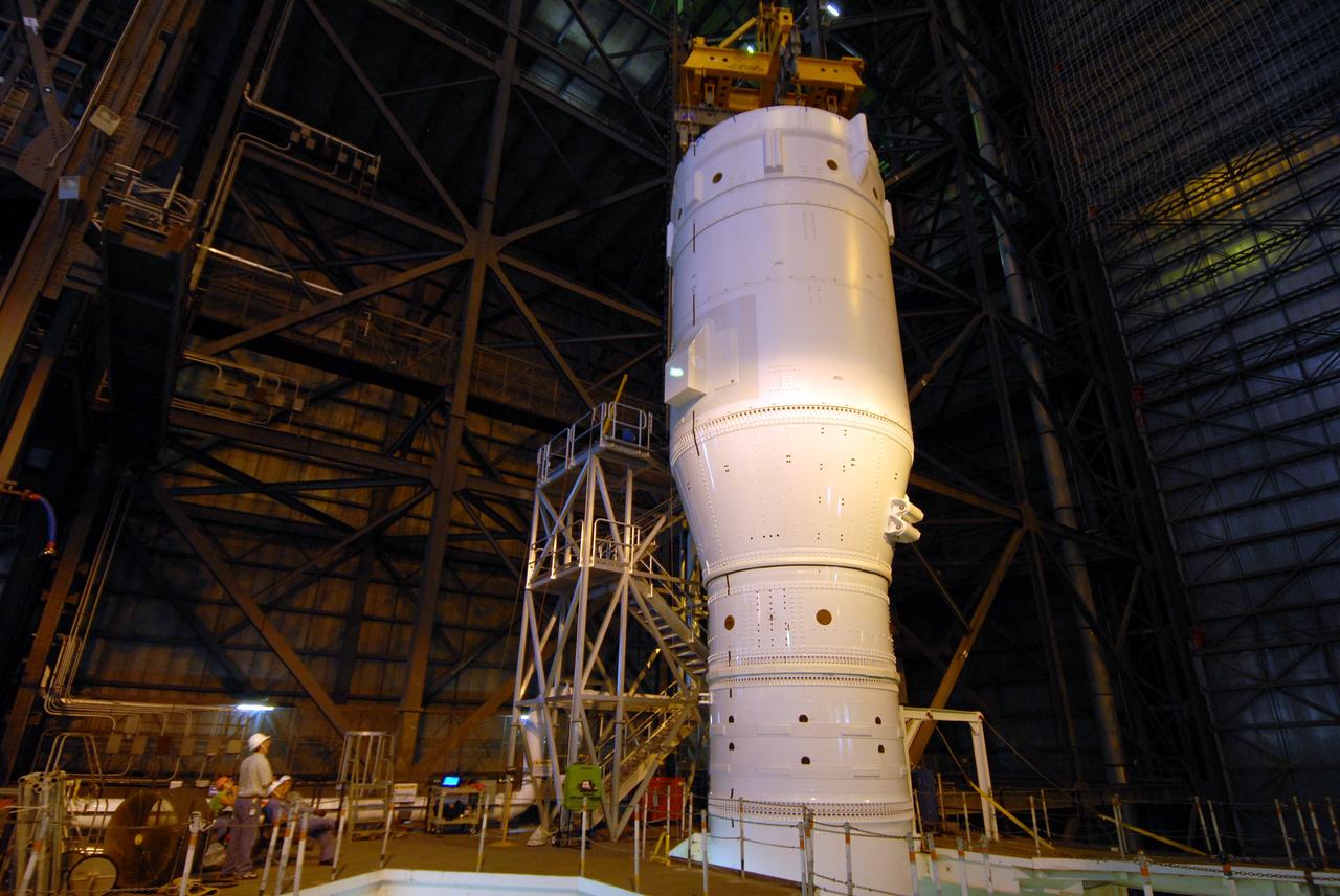
Ares 1-X segment US-3 being lifted onto the cart prior to being stacked onto US-2 to start forming the Ares 1-X USS Super Stack

This supernova in the constellation Cassiopeia was observed by Tycho Brahe in 1572. In this x-ray image from the High Energy Astronomy Observatory (HEAO-2/Einstein Observatory produced by nearly a day of exposure time, the center region appears filled with emissions that can be resolved into patches or knots of material. However, no central pulsar or other collapsed object can be seen. The HEAO-2, the first imaging and largest x-ray telescope built to date, was capable of producing actual photographs of x-ray objects. Shortly after launch, the HEAO-2 was nicknamed the Einstein Observatory by its scientific experimenters in honor of the centernial of the birth of Albert Einstein, whose concepts of relativity and gravitation have influenced much of modern astrophysics, particularly x-ray astronomy. The HEAO-2, designed and developed by TRW, Inc. under the project management of the Marshall Space Flight Center, was launched aboard an Atlas/Centaur launch vehicle on November 13, 1978.
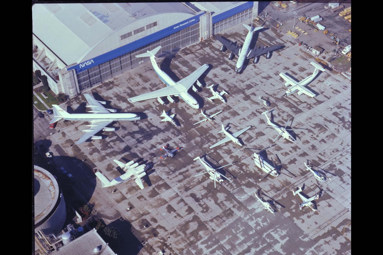
NASA Aircraft on ramp (Aerial view) Sides: (L) QSRA (R) C-8A AWJSRA - Back to Front: CV-990 (711) C-141 KAO, CV-990 (712) Galileo, T-38, YO-3A, Lear Jet, X-14, U-2, OH-6, CH-47, SH-3G, RSRA, AH-1G, XV-15, UH-1H
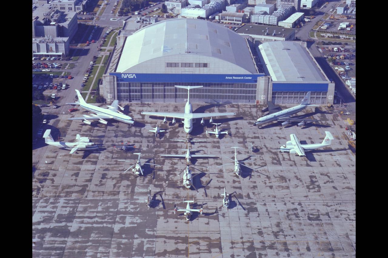
NASA Aircraft on ramp (Aerial view) Sides: (L) QSRA (R) C-8A AWJSRA - Back to Front: CV-990 (711) C-141 KAO, CV-990 (712) Galileo, T-38, YO-3A, Lear Jet, X-14, U-2, OH-6, CH-47, SH-3G, RSRA, AH-1G, XV-15, UH-1H
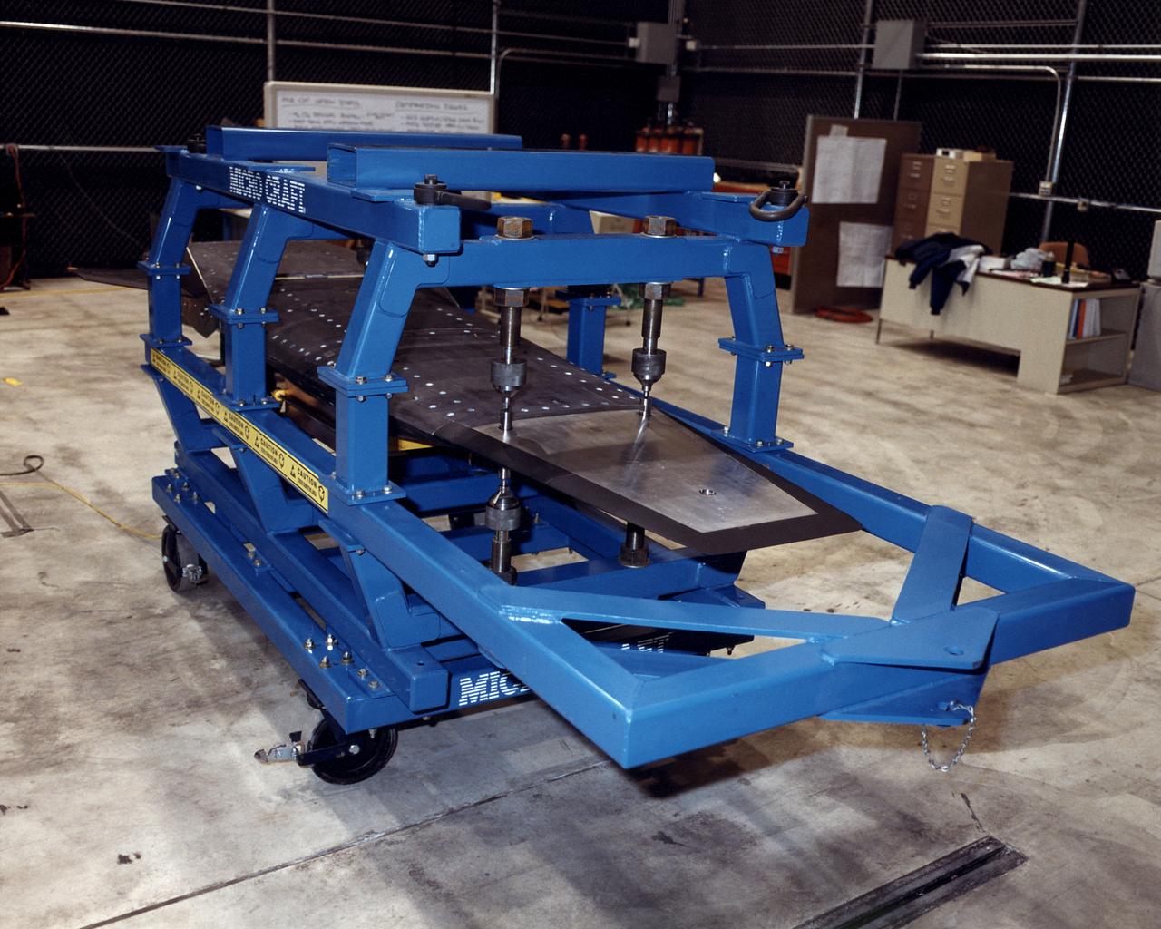
The second of three X-43A hypersonic research aircraft, shown here in its protective shipping jig, arrived at NASA's Dryden Flight Research Center, Edwards, California, on January 31, 2001. The arrival of the second X-43A from its manufacturer, MicroCraft, Inc., of Tullahoma, Tenn., followed by only a few days the mating of the first X-43A and its specially-designed adapter to the first stage of a modified Pegasus® booster rocket. The booster, built by Orbital Sciences Corp., Dulles, Va., will accelerate the 12-foot-long, unpiloted research aircraft to a predetermined altitude and speed after the X-43A/booster "stack" is air-launched from NASA's venerable NB-52 mothership. The X-43A will then separate from the rocket and fly a pre-programmed trajectory, conducting aerodynamic and propulsion experiments until it impacts into the Pacific Ocean. Three research flights are planned, two at Mach 7 and one at Mach 10 (seven and 10 times the speed of sound respectively) with the first tentatively scheduled for early summer, 2001. The X-43A is powered by a revolutionary supersonic-combustion ramjet ("scramjet") engine, and will use the underbody of the aircraft to form critical elements of the engine. The forebody shape helps compress the intake airflow, while the aft section acts as a nozzle to direct thrust. The X-43A flights will be the first actual flight tests of an aircraft powered by an air-breathing scramjet engine.

This photograph was taken during the assembly of the High Energy Astronomy Observatory (HEAO)-2 at TRW, Inc., the prime contractor for the HEAOs. The HEAO-2, the first imaging and largest x-ray telescope built to date, was capable of producing actual photographs of x-ray objects. TRW, Inc. designed and developed the HEAO, under the project management of the Marshall Space Flight Center. The HEAO-2 was originally identified as HEAO-B but the designation was changed once the spacecraft achieved orbit.

Like the Crab Nebula, the Vela Supernova Remnant has a radio pulsar at its center. In this image taken by the High Energy Astronomy Observatory (HEAO)-2/Einstein Observatory, the pulsar appears as a point source surrounded by weak and diffused emissions of x-rays. HEAO-2's computer processing system was able to record and display the total number of x-ray photons (a tiny bundle of radiant energy used as the fundamental unit of electromagnetic radiation) on a scale along the margin of the picture. The HEAO-2, the first imaging and largest x-ray telescope built to date, was capable of producing actual photographs of x-ray objects. Shortly after launch, the HEAO-2 was nicknamed the Einstein Observatory by its scientific experimenters in honor of the centernial of the birth of Albert Einstein, whose concepts of relativity and gravitation have influenced much of modern astrophysics, particularly x-ray astronomy. The HEAO-2, designed and developed by TRW, Inc. under the project management of the Marshall Space Flight Center, was launched aboard an Atlas/Centaur launch vehicle on November 13, 1978.
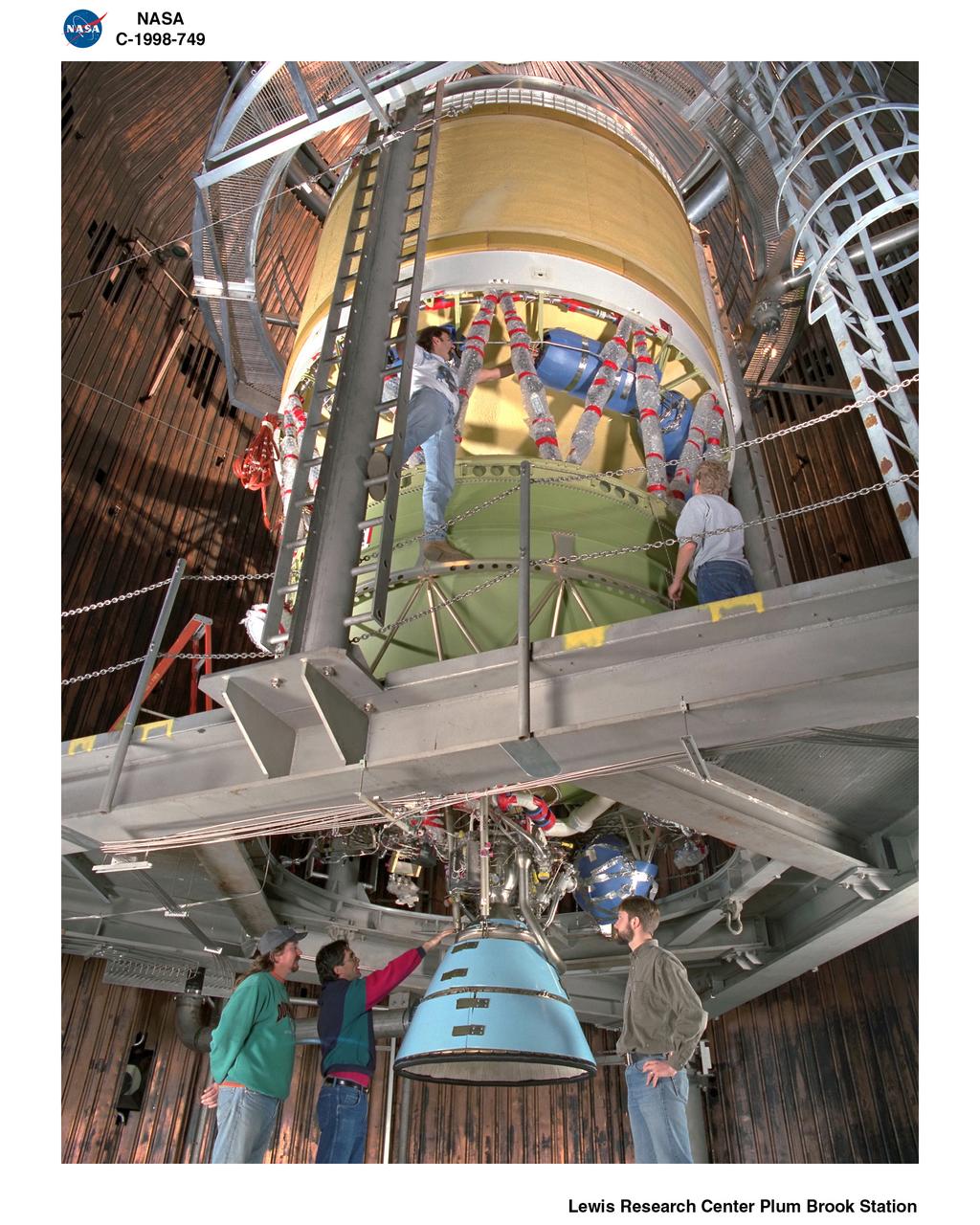
NASA PLUM BROOK B-2 X STAGE TEST ARTICLE AND TEAM PICTURES
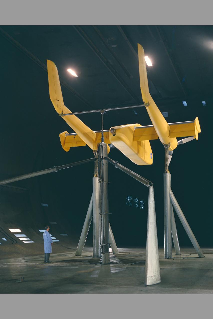
2-Prop. R.C.F. (Rotating Cylinder Flap) in 40 x 80ft. wind tunnel. - rear view with Chuck Greco.

2-Prop. R.C.F. (Rotating Cylinder Flap) in 40 x 80ft. wind tunnel. front view detail of flap
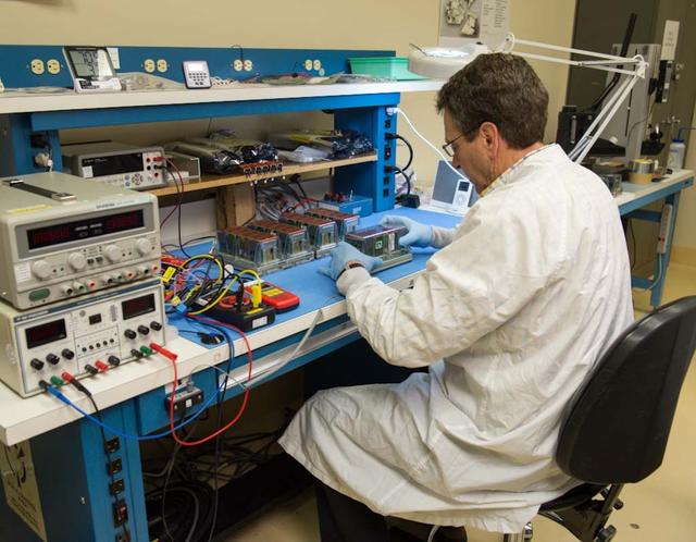
TROPI Seed Growth-1 payload (will fly to ISS on Space X 2) with John Freeman, Intrinsyx @ Ames, Plant Scientist
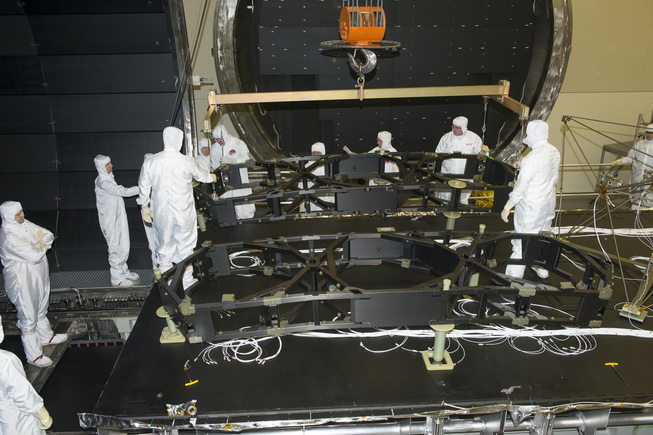
JWST (JAMES WEBB SPACE TELESCOPE) WING #2 INSTALLATION IN THE XRCF (X-RAY & CRYOGENIC FACILITY) PRIOR TO TESTING
2-Prop. R.C.F. (Rotating Cylinder Flap) in 40 x 80ft. wind tunnel. rear view detail of flap
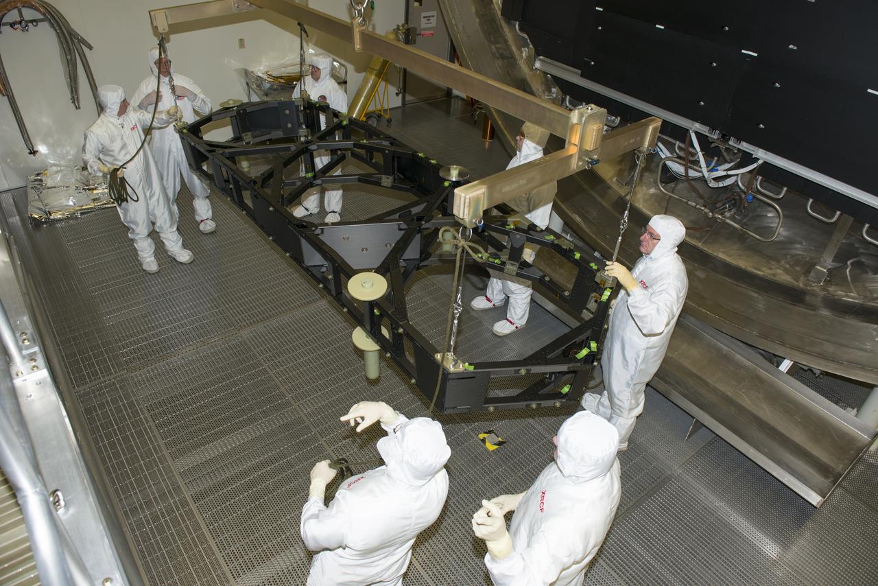
JWST (JAMES WEBB SPACE TELESCOPE) WING #2 INSTALLATION IN THE XRCF (X-RAY & CRYOGENIC FACILITY) PRIOR TO TESTING
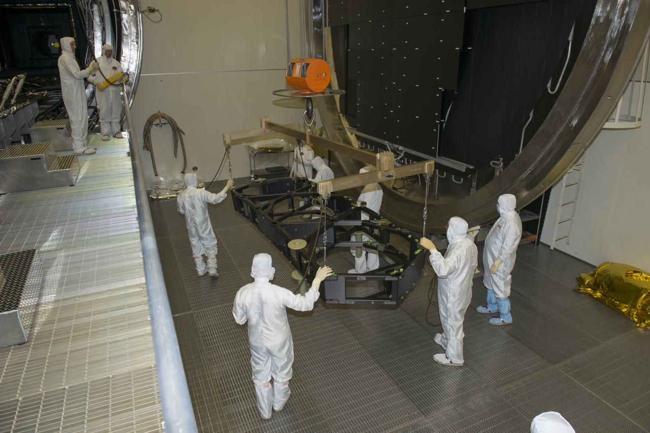
JWST (JAMES WEBB SPACE TELESCOPE) WING #2 INSTALLATION IN THE XRCF (X-RAY & CRYOGENIC FACILITY) PRIOR TO TESTING

This artist's concept depicts the High Energy Astronomy Observatory (HEAO)-2 in orbit. The HEAO-2, the first imaging and largest x-ray telescope built to date, was capable of producing actual photographs of x-ray objects. Shortly after launch, the HEAO-2 was nicknamed the Einstein Observatory by its scientific experimenters in honor of the centernial of the birth of Albert Einstein, whose concepts of relativity and gravitation have influenced much of modern astrophysics, particularly x-ray astronomy. The HEAO-2, designed and developed by TRW, Inc. under the project management of the Marshall Space Flight Center, was launched aboard an Atlas/Centaur launch vehicle on November 13, 1978. The HEAO-2 was originally identified as HEAO-B but the designation was changed once the spacecraft achieved orbit.
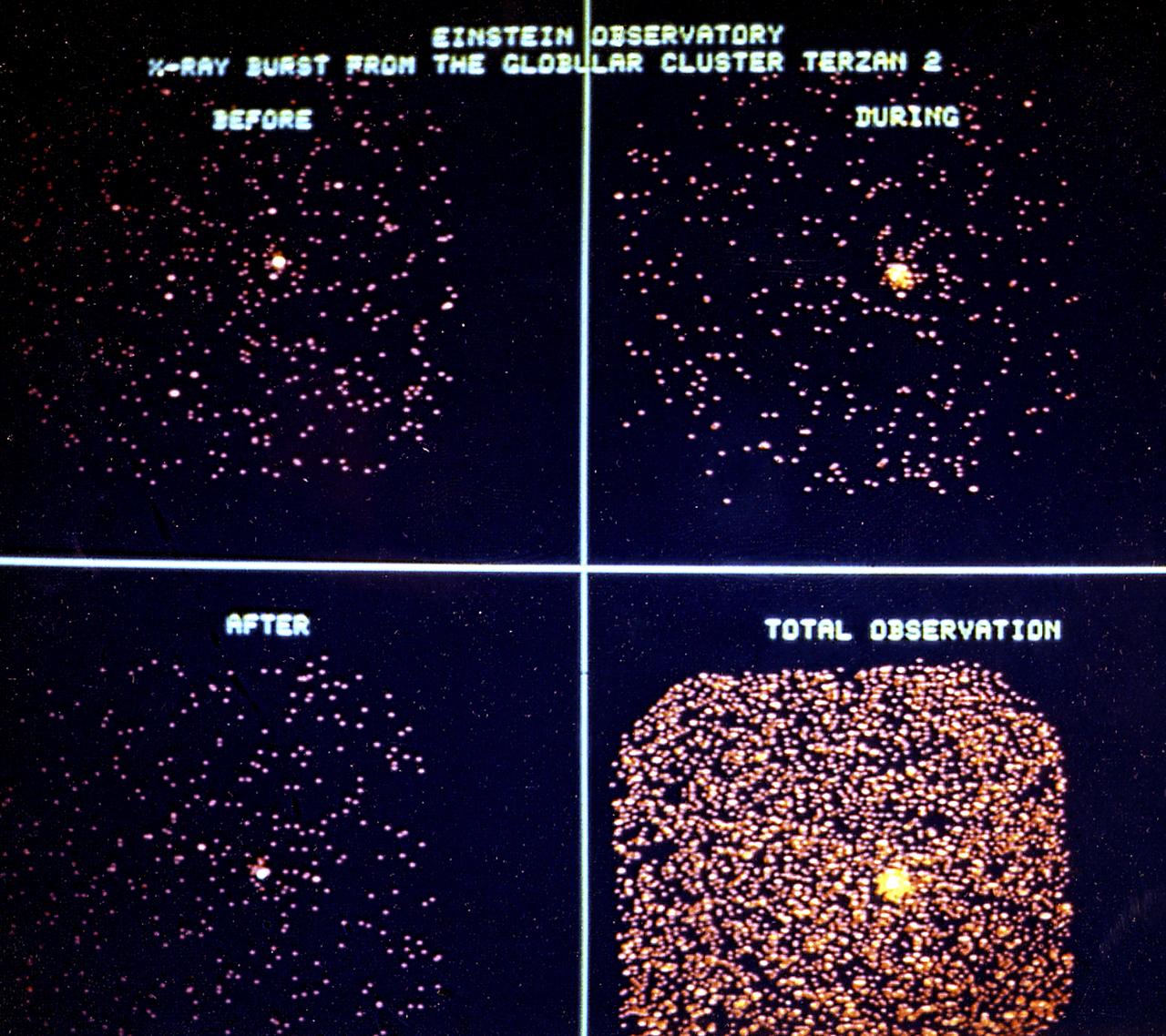
The dramatic change in x-ray emission from the Terzan 2 cluster is shown in this series of 2.5-minute exposures taken with the High Energy Astronomy Observatory (HEAO)-2/Einstein Observatory immediately before, during, and after the burst. Total exposure (20 minutes) of the object, including the outburst, is shown in the fourth photograph. These images represent the first observation of an x-ray burst in progress. The actual burst lasted 50 seconds. Among the rarest, and most bizarre, phenomena observed by x-ray astronomers are the so-called cosmic bursters (x-ray sources that suddenly and dramatically increase in intensity then subside). These sudden bursts of intense x-ray radiation apparently come from compact objects with a diameter smaller than 30 miles (48 kilometers). Yet, despite their minuscule size, a typical x-ray burster can release more x-ray energy in a single brief burst than our Sun does in an entire week. The HEAO-2, the first imaging and largest x-ray telescope built to date, was capable of producing actual photographs of x-ray objects. Shortly after launch, the HEAO-2 was nicknamed the Einstein Observatory by its scientific experimenters in honor of the centernial of the birth of Albert Einstein, whose concepts of relativity and gravitation have influenced much of modern astrophysics, particularly x-ray astronomy. The HEAO was designed and developed by TRW, Inc. under the project management of the Marshall Space Flight Center.
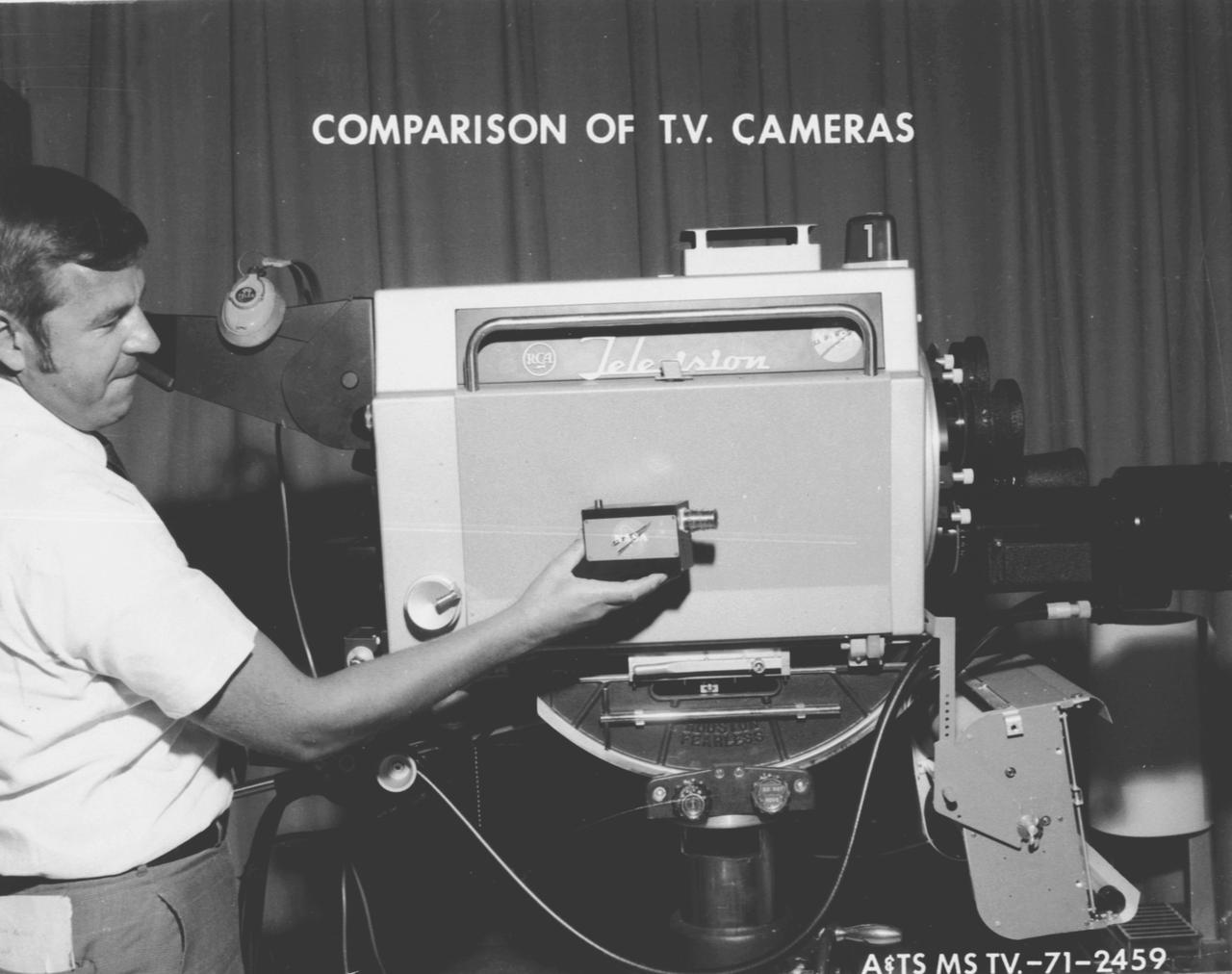
Originally devised to observe Saturn stage separation during Apollo flights, Marshall Space Flight Center's Miniature Television Camera, measuring only 4 x 3 x 1 1/2 inches, quickly made its way to the commercial telecommunications market.

ATK TEAM PHOTOGRAPH WITH THE 2 JWST (JAMES WEBB SPACE TELESCOPE) WINGS AFTER INSTALLATION IN THE XRCF (X-RAY & CRYOGENIC FACILITY)
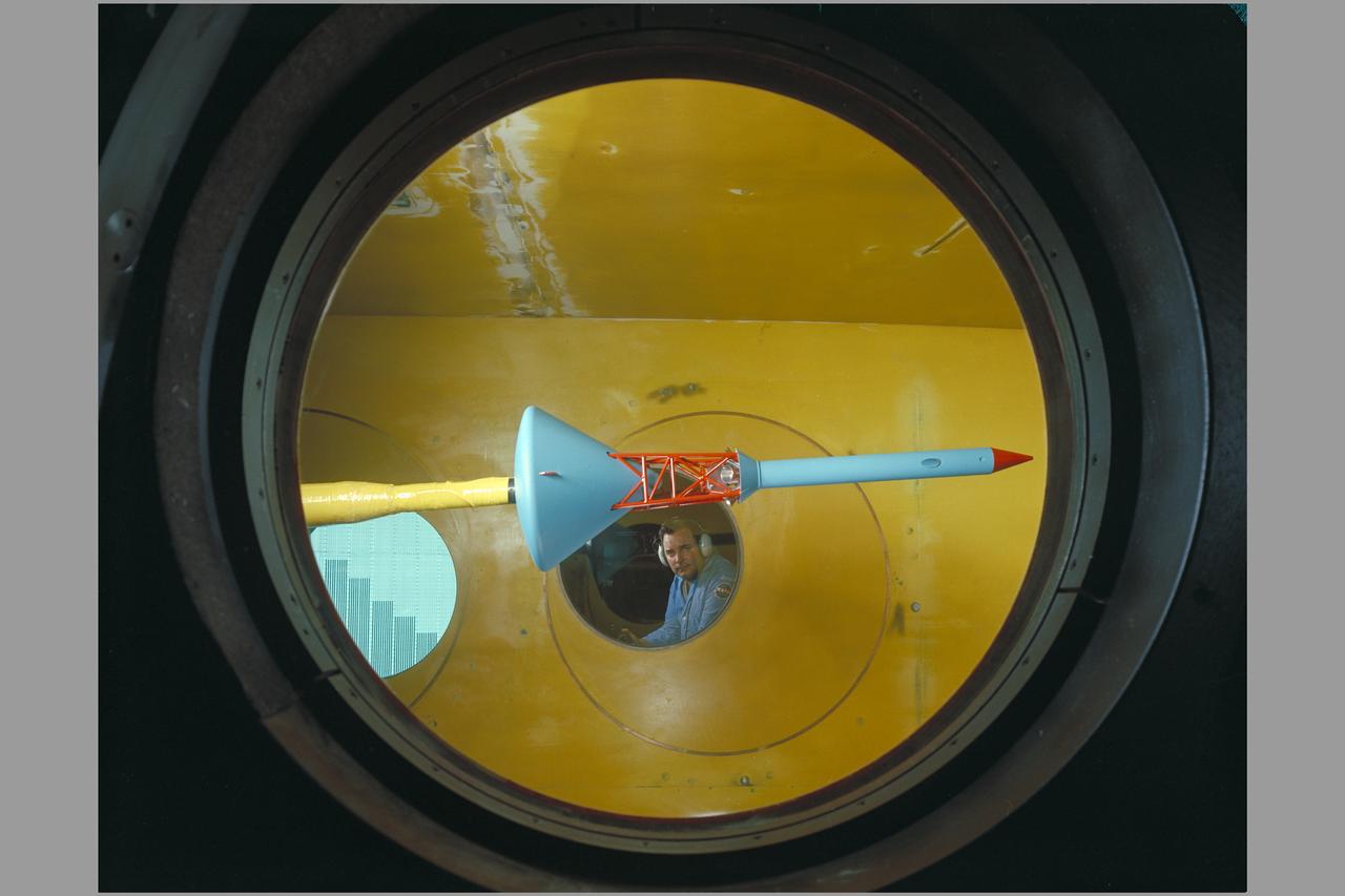
Side view of assembled command module, tower with flap & launch-escape rocket. Apollo FS-2 in 9 x 7 ft. SupersonicWind Tunnel.

2-Prop. R.C.F. (Rotating Cylinder Flap) in 40 x 80ft. wind tunnel. 3/4 front view with Jim Weiberg Chuck Greco.
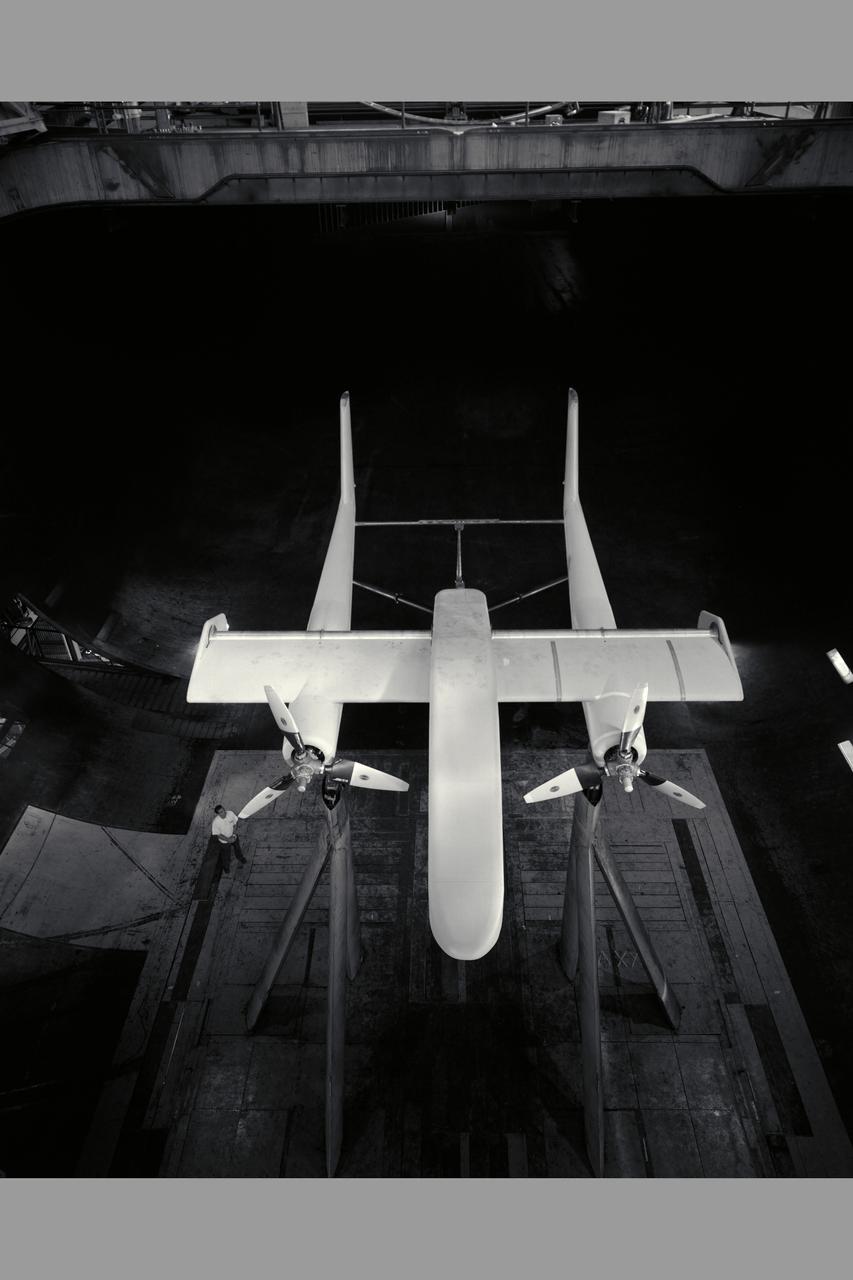
2-Prop. R.C.F. (Rotating Cylinder Flap) in 40 x 80ft. wind tunnel - overhead view propeller spinning with Chuck Greco.
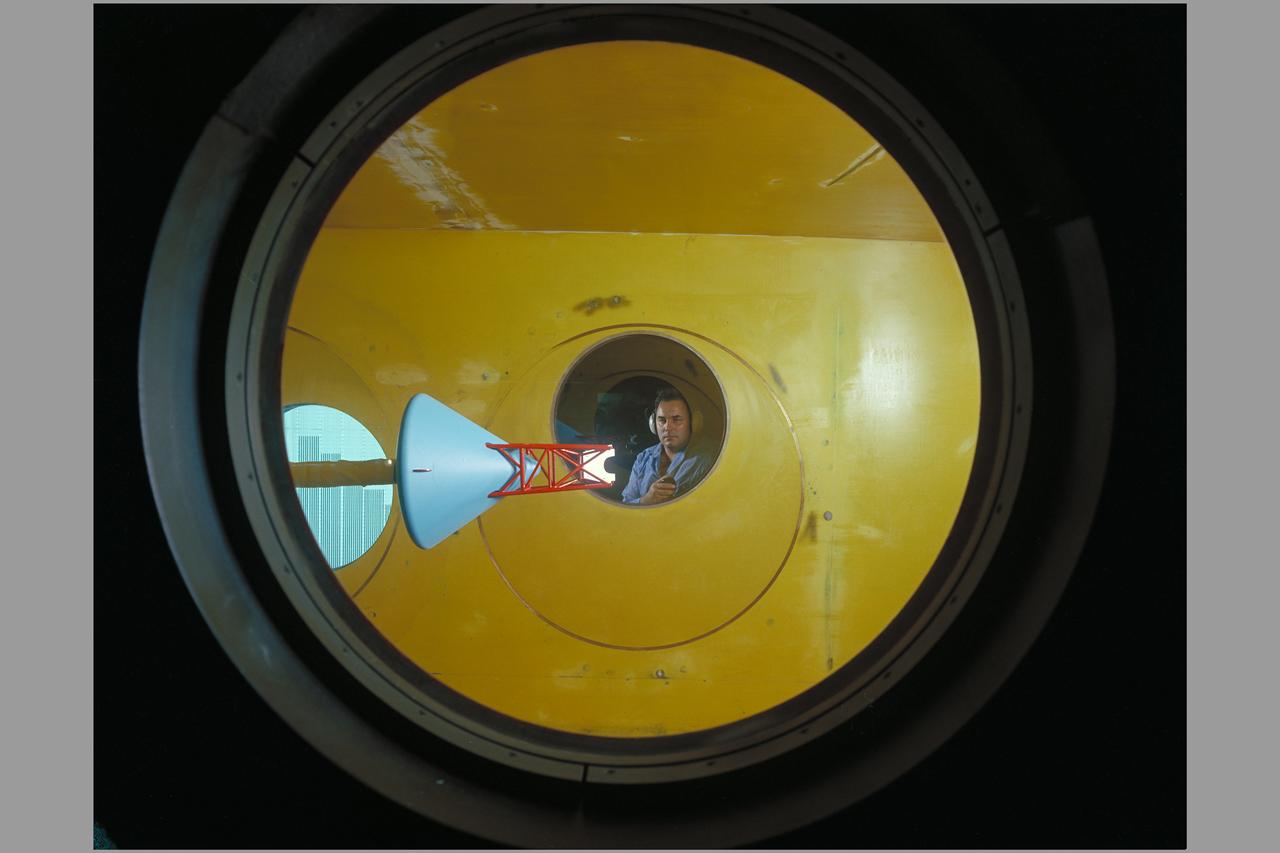
Side view of assembled command module, tower with flap & launch-escape rocket. Apollo FS-2 in 9 x 7 ft. SupersonicWind Tunnel.
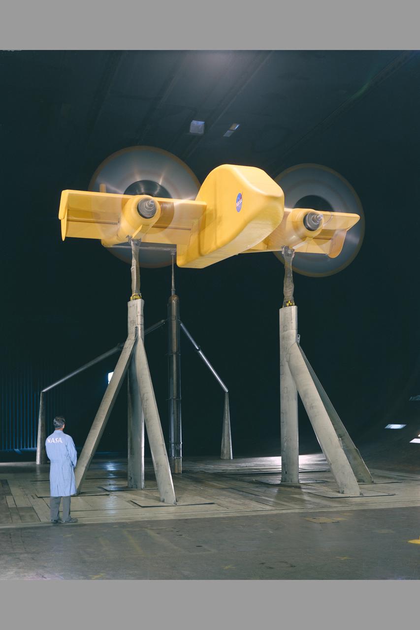
2-Prop. R.C.F. (Rotating Cylinder Flap) in 40 x 80ft. wind tunnel. 3/4 front view propeller spinning with Chuck Greco.
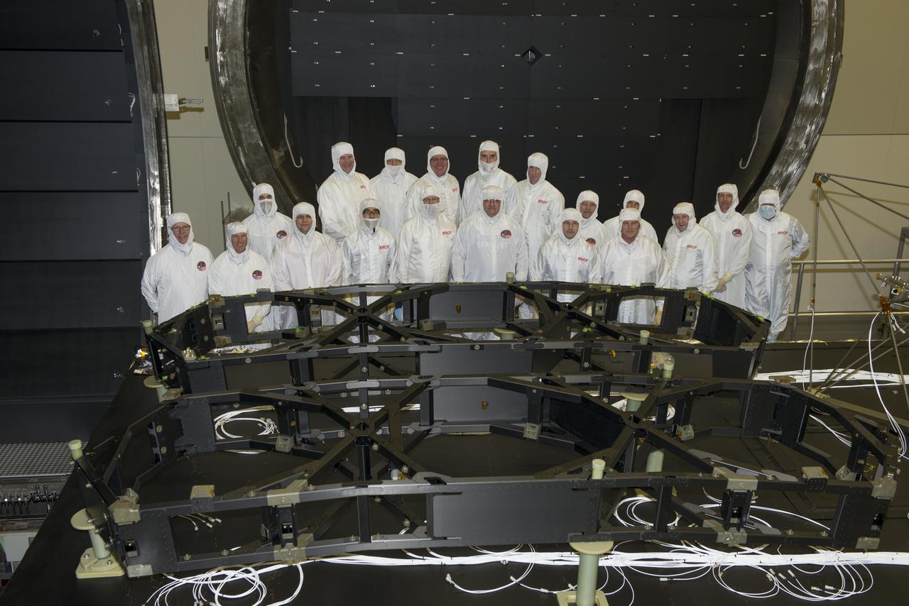
NASA AND ATK TEAM PHOTOGRAPH WITH THE 2 JWST (JAMES WEBB SPACE TELESCOPE) WINGS AFTER INSTALLATION IN THE XRCF (X-RAY & CRYOGENIC FACILITY)
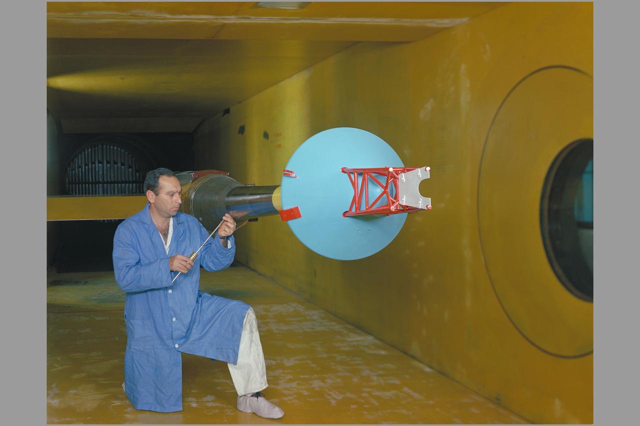
Side view of assembled command module, tower with flap & launch-escape rocket. Apollo FS-2 in 9 x 7 ft. SupersonicWind Tunnel.

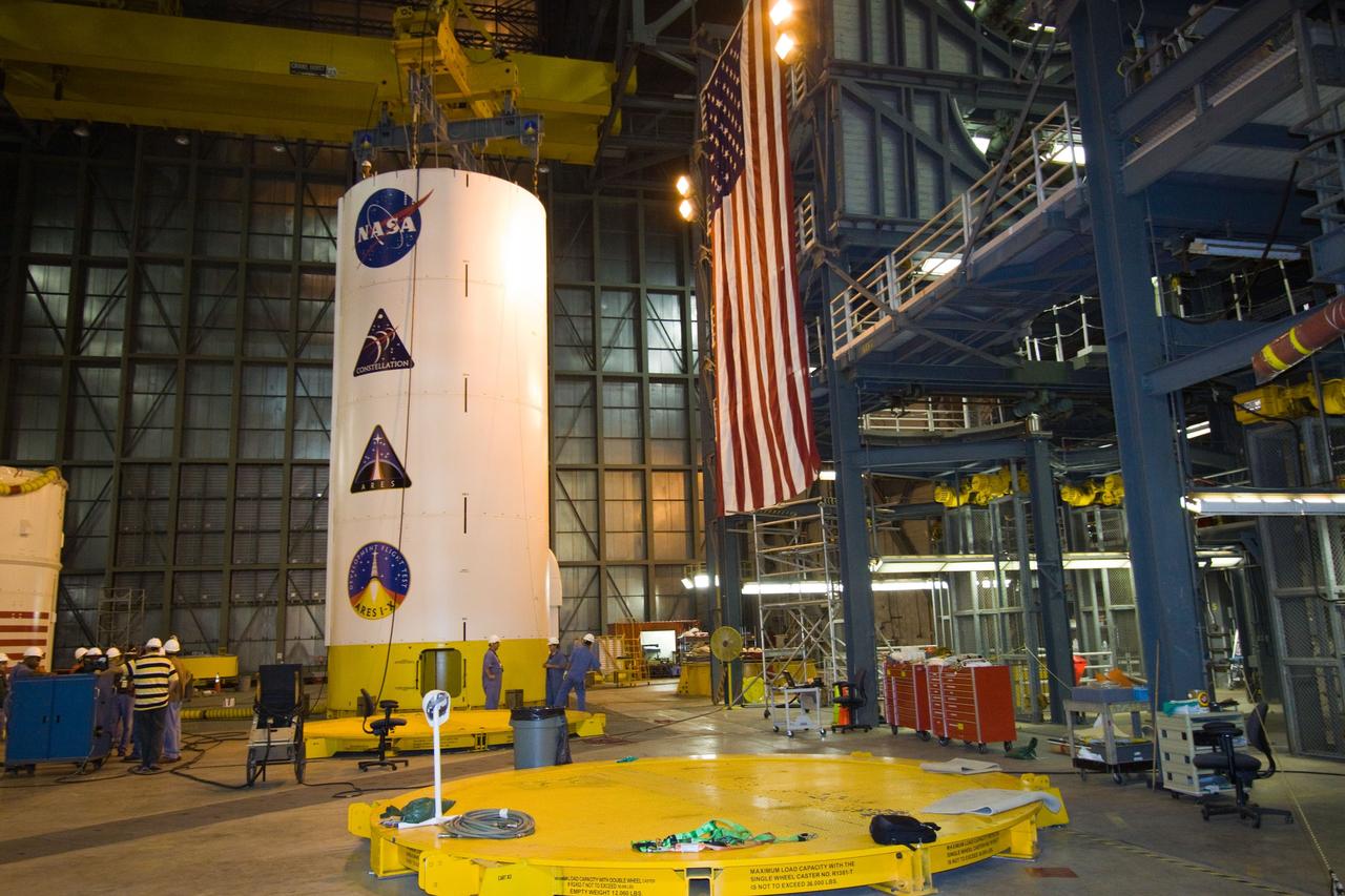
The first of Ares 1-X Flight Segments, the US-2 being stacked onto the SSAS (Super Structure Assembly Stand). This is the first formaiton of the Super Stack

This image is an x-ray view of Eta Carinae Nebula showing bright stars taken with the High Energy Astronomy Observatory (HEAO)-2/Einstein Observatory. The Eta Carinae Nebula is a large and complex cloud of gas, crisscrossed with dark lanes of dust, some 6,500 light years from Earth. Buried deep in this cloud are many bright young stars and a very peculiar variable star. The HEAO-2, the first imaging and largest x-ray telescope built to date, was capable of producing actual photographs of x-ray objects. Shortly after launch, the HEAO-2 was nicknamed the Einstein Observatory by its scientific experimenters in honor of the centernial of the birth of Albert Einstein, whose concepts of relativity and gravitation have influenced much of modern astrophysics, particularly x-ray astronomy. The HEAO-2, designed and developed by TRW, Inc. under the project management of the Marshall Space Flight Center, was launched aboard an Atlas/Centaur launch vehicle on November 13, 1978.

This image is an observation of Quasar 3C 273 by the High Energy Astronomy Observatory (HEAO)-2/Einstein Observatory. It reveals the presence of a new source (upper left) with a red shift that indicates that it is about 10 billion light years away. Quasars are mysterious, bright, star-like objects apparently located at the very edge of the visible universe. Although no bigger than our solar system, they radiate as much visible light as a thousand galaxies. Quasars also emit radio signals and were previously recognized as x-ray sources. The HEAO-2, the first imaging and largest x-ray telescope built to date, was capable of producing actual photographs of x-ray objects. Shortly after launch, the HEAO-2 was nicknamed the Einstein Observatory by its scientific experimenters in honor of the centernial of the birth of Albert Einstein, whose concepts of relativity and gravitation have influenced much of modern astrophysics, particularly x-ray astronomy. The HEAO-2 was designed and developed by TRW, Inc. under the project management of the Marshall Space Flight Center.
TROPI Seed Growth-1 payload (will fly to ISS on Space X 2) with Thomas Neidermaier, Europeon Modular Culitivation System Payload Intergration Manager both from Astrium Space Transportaton, Friedrichshafen, Germany.
TROPI Seed Growth-1 payload (will fly to ISS on Space X 2) with Reinhard Born, Astrium Space Transportaton, Friedrichshafen, Germany - Europeon Modular Culitivation System Payload Engineering Manager
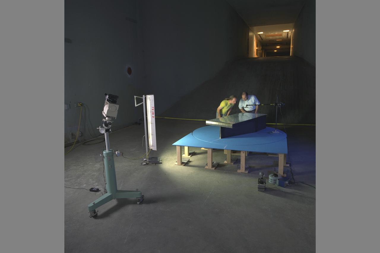
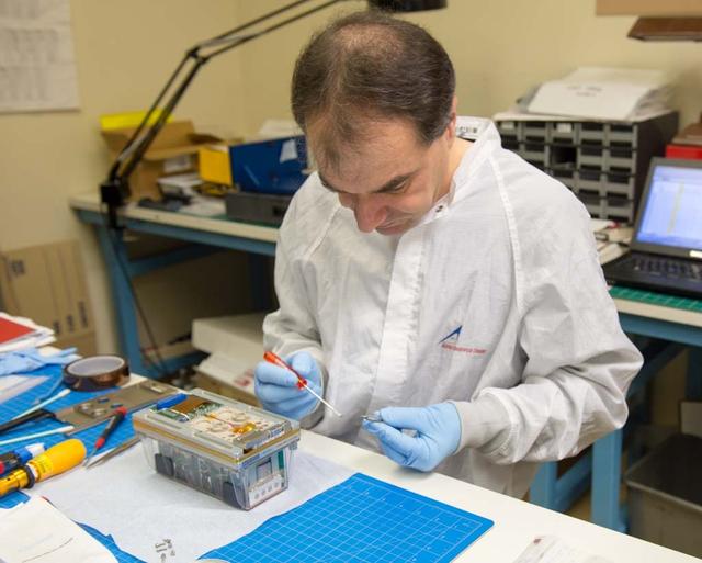
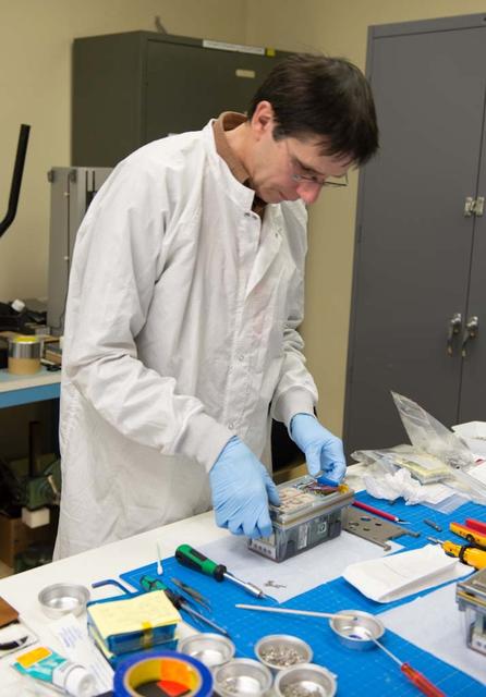
Test Setup and UltraViolet (UV) Lighting with Frank Caradonna, Ames and Kurtis Long, Project Scientist. Ship Airwake Investigation 7 x 10 ft#2 Wind Tunnel Settling Chamber.
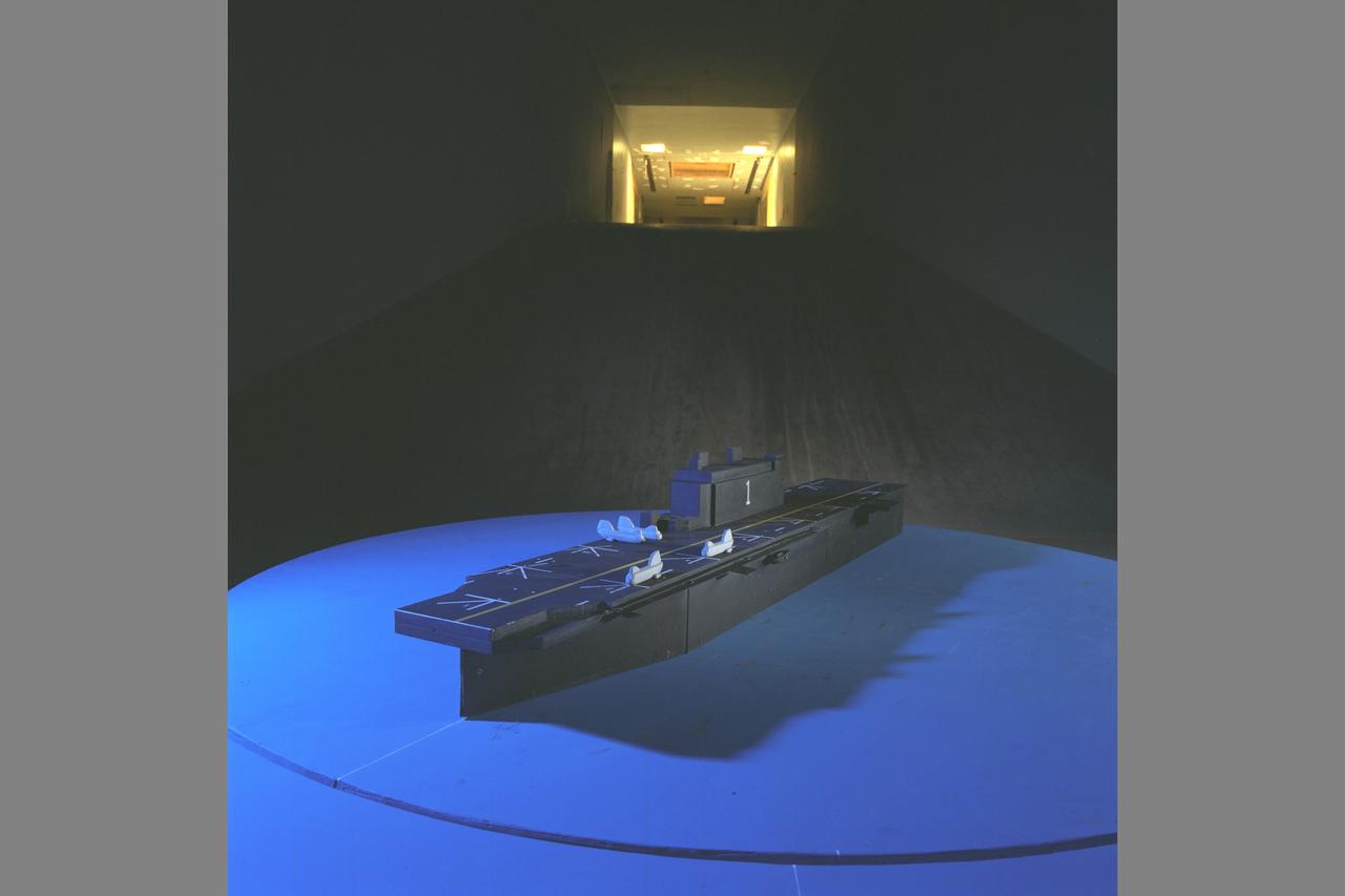
Test Setup and UltraViolet (UV) Lighting and Tufts. Ship Airwake Investigation 7 x 10 ft#2 Wind Tunnel Settling Chamber. Bridge and rotorcraft added to flight deck
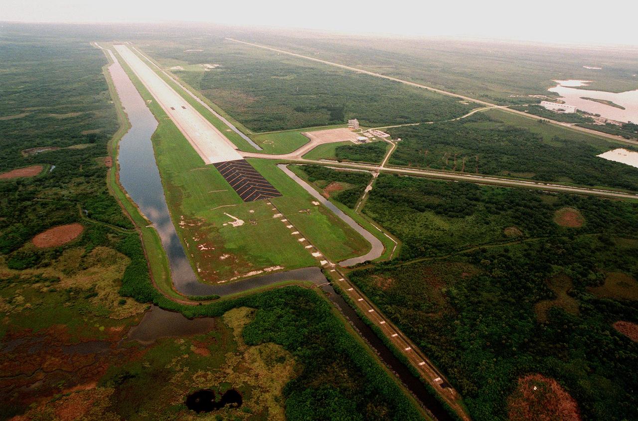
North of the Launch Complex 39 Area, the Shuttle Landing Facility (SLF) stretches to the northwest. One of the largest runways in the world, the runway is located 3.2 km (2 miles) northwest of the Vehicle Assembly Building and is 4,572 meters (15,000 ft) long and 91.4 meters (300 ft) wide -- about as wide as the length of a football field. It has 305 meters (1000 ft) of paved overruns at each end and the paving thickness is 40.6cm (15 in) at the center. The facility includes a 150 x 168-meter (490 ft x 550 ft) parking apron (at right) and a 3.2-km (2-mile) tow-way connecting it with the Orbiter Processing Facility.
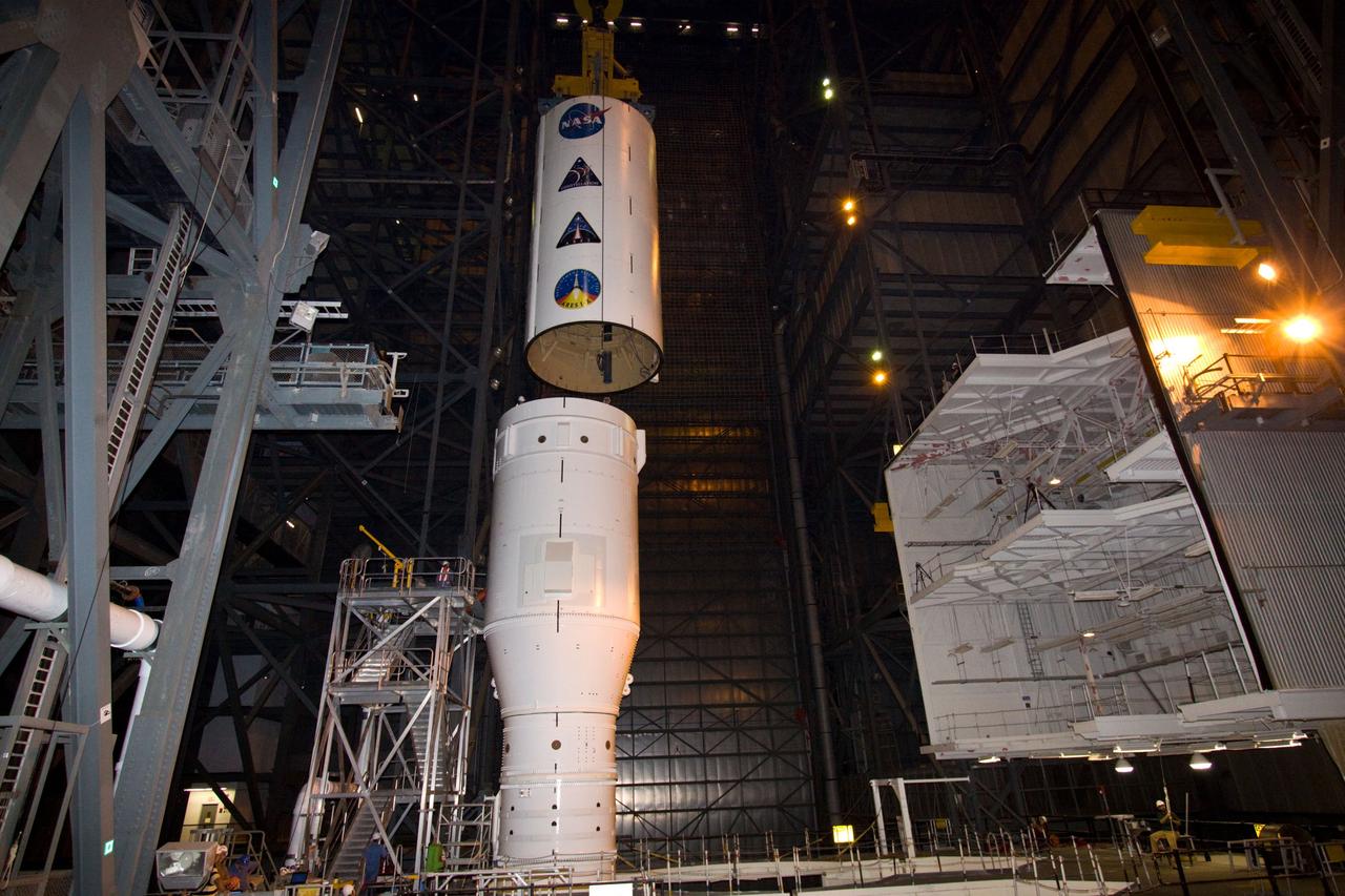
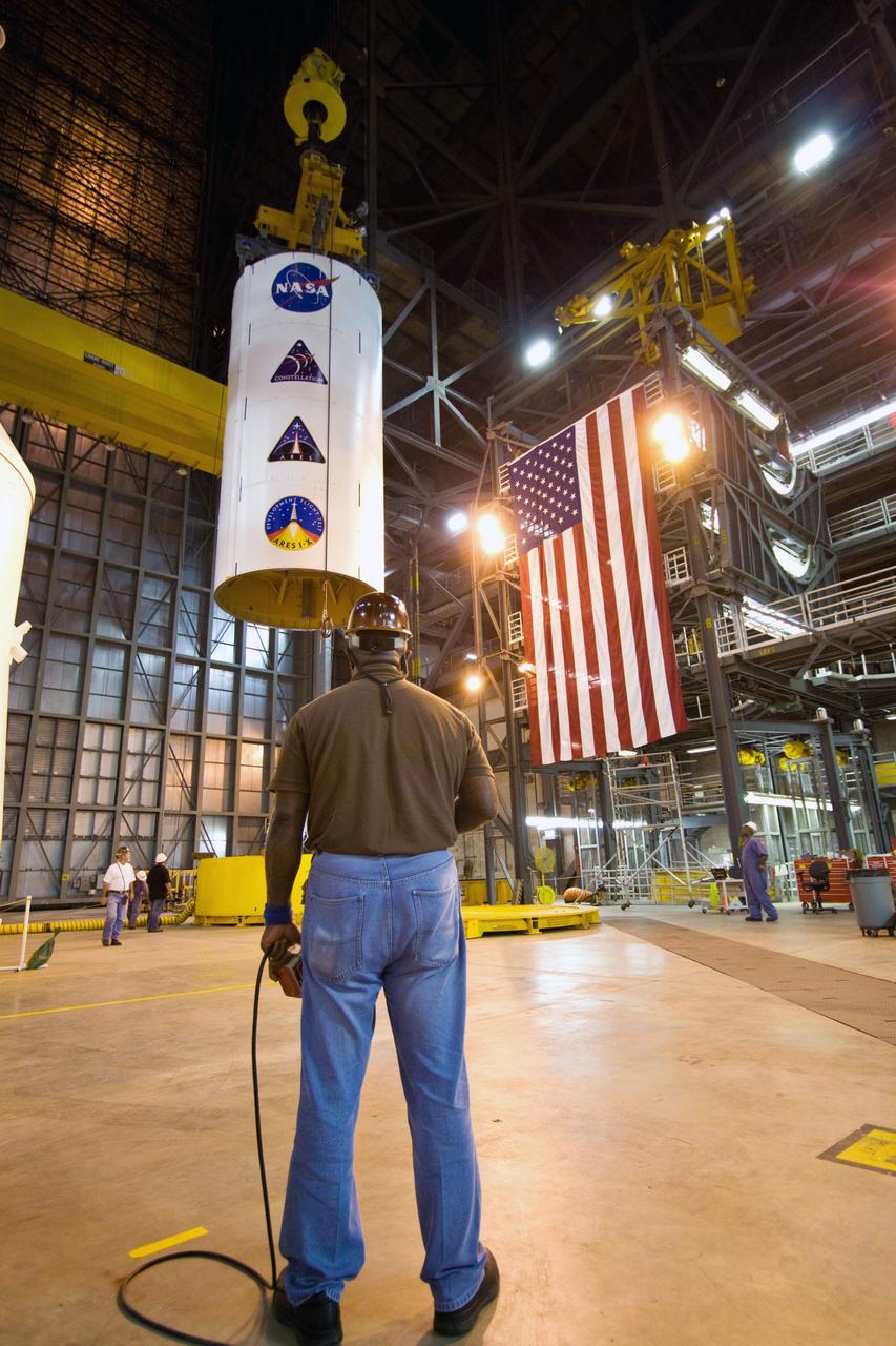
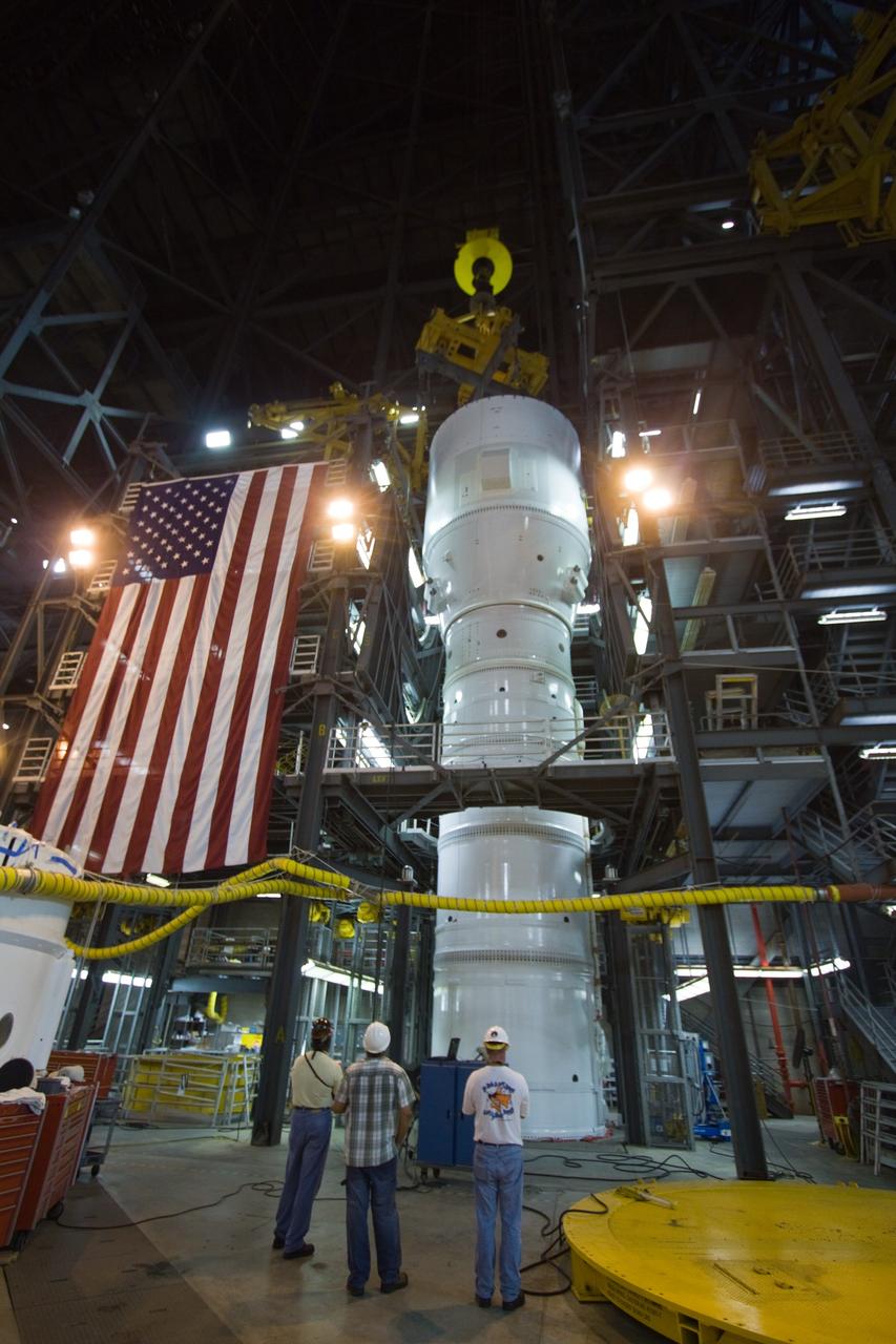
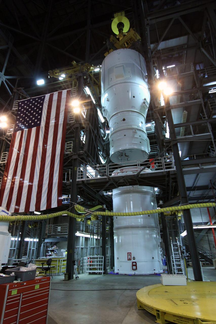
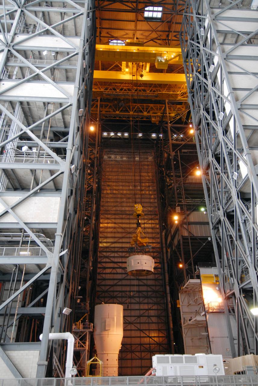
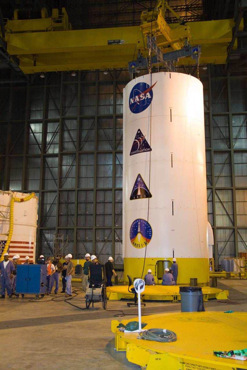
CAPE CANAVERAL, Fla. – In NASA Kennedy Space Center's Vehicle Assembly Building High Bay 4, a crane lowers the Ares I-X Super Stack 3 toward Super Stack 2 for integration. The upper stage comprises five super stacks, which are integrated with the four-segment solid rocket booster first stage on the mobile launch platform. Ares I-X is the test vehicle for the Ares I, which is part of the Constellation Program to return men to the moon and beyond. The Ares I-X flight test is targeted for Oct. 31, pending formal NASA Headquarters approval. Photo credit: NASA/Jack Pfaller

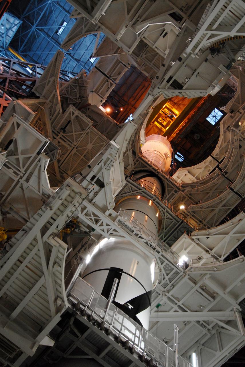
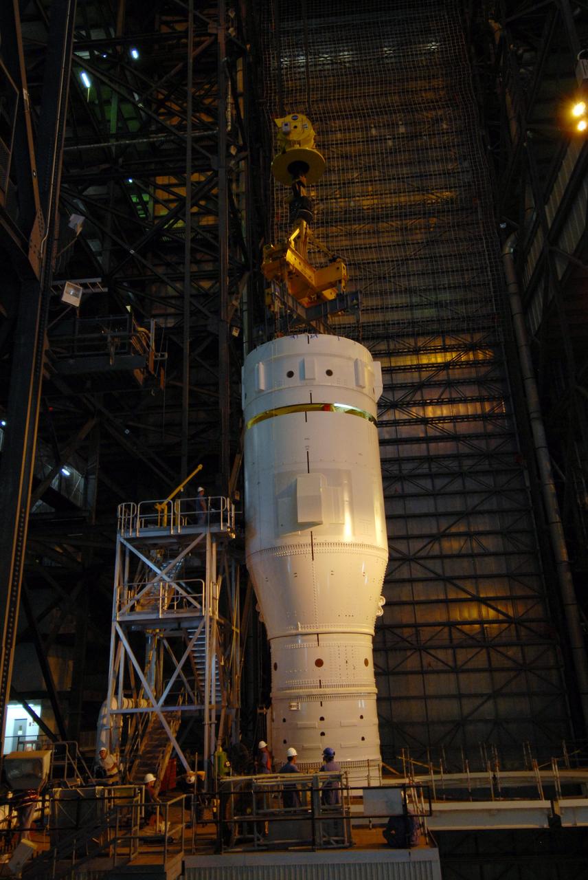
CAPE CANAVERAL, Fla. – In the Vehicle Assembly Building's High Bay 3, the Ares I-X "super stack 1" is being attached to the forward motor segment. Super stack 1 comprises the frustum, forward skirt, forward skirt extension, interstages 1 and 2 and the fifth segment simulator. Ares I-X is the test vehicle for the Ares I, which is part of the Constellation Program to return men to the moon and beyond. The Ares I-X flight test is targeted for Oct. 31, pending forma NASA Headquarters approval. Photo credit: NASA/Jack Pfaller
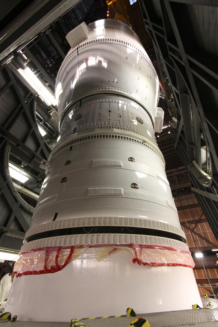
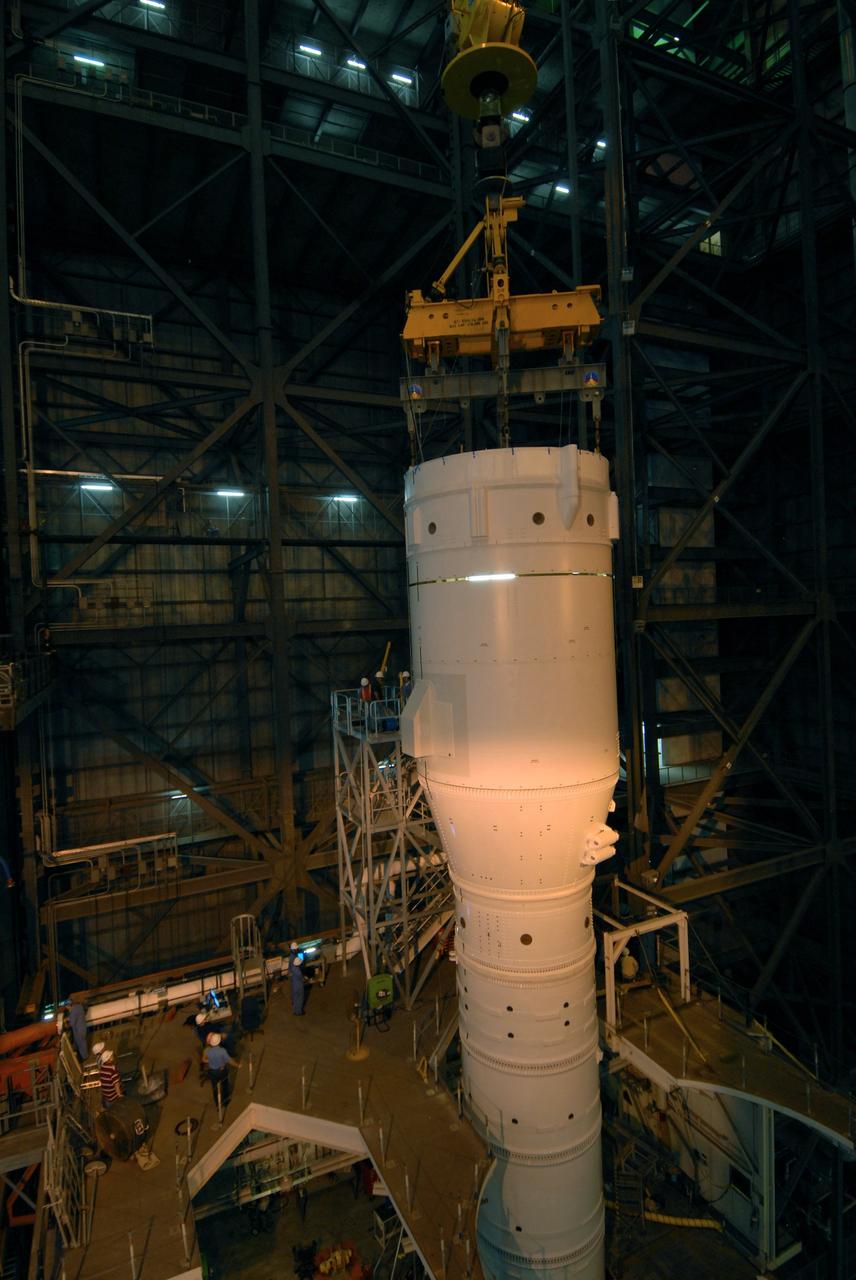
CAPE CANAVERAL, Fla. – In the Vehicle Assembly Building at NASA's Kennedy Space Center in Florida, segments of the Ares I-X first stage are lowered onto the fifth simulator segment for mating, to complete Super Stack 1. The super stack comprises the forward skirt, forward skirt extension, interstages 1 and 2 and the fifth segment simulator. Ares I-X is the test vehicle for the Ares I, which is part of the Constellation Program to return men to the moon and beyond. The Ares I-X flight test is targeted no earlier than Aug. 30 from Launch Pad 39B. Photo credit: NASA/Jack Pfaller

CAPE CANAVERAL, Fla. – In the Vehicle Assembly Building's High Bay 3, the Ares I-X "super stack 1" is being attached to the forward motor segment. Super stack 1 comprises the frustum, forward skirt, forward skirt extension, interstages 1 and 2 and the fifth segment simulator. Ares I-X is the test vehicle for the Ares I, which is part of the Constellation Program to return men to the moon and beyond. The Ares I-X flight test is targeted for Oct. 31, pending forma NASA Headquarters approval. Photo credit: NASA/Jack Pfaller
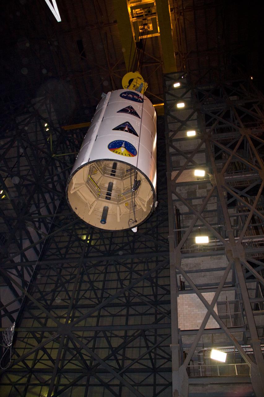
CAPE CANAVERAL, Fla. – In NASA Kennedy Space Center's Vehicle Assembly Building, a crane is attached to the Ares I-X Super Stack 3 in High Bay 3. The stack is being moved to High Bay 4 for integration with Super Stack 2. The upper stage comprises five super stacks, which are integrated with the four-segment solid rocket booster first stage on the mobile launch platform. Ares I-X is the test vehicle for the Ares I, which is part of the Constellation Program to return men to the moon and beyond. The Ares I-X flight test is targeted for Oct. 31, pending formal NASA Headquarters approval. Photo credit: NASA/Jack Pfaller
CAPE CANAVERAL, Fla. – In NASA Kennedy Space Center's Vehicle Assembly Building, a crane lowers the Ares I-X Super Stack 3 into High Bay 4. There it will be integrated with Super Stack 2. The upper stage comprises five super stacks, which are integrated with the four-segment solid rocket booster first stage on the mobile launch platform. Ares I-X is the test vehicle for the Ares I, which is part of the Constellation Program to return men to the moon and beyond. The Ares I-X flight test is targeted for Oct. 31, pending formal NASA Headquarters approval. Photo credit: NASA/Jack Pfaller
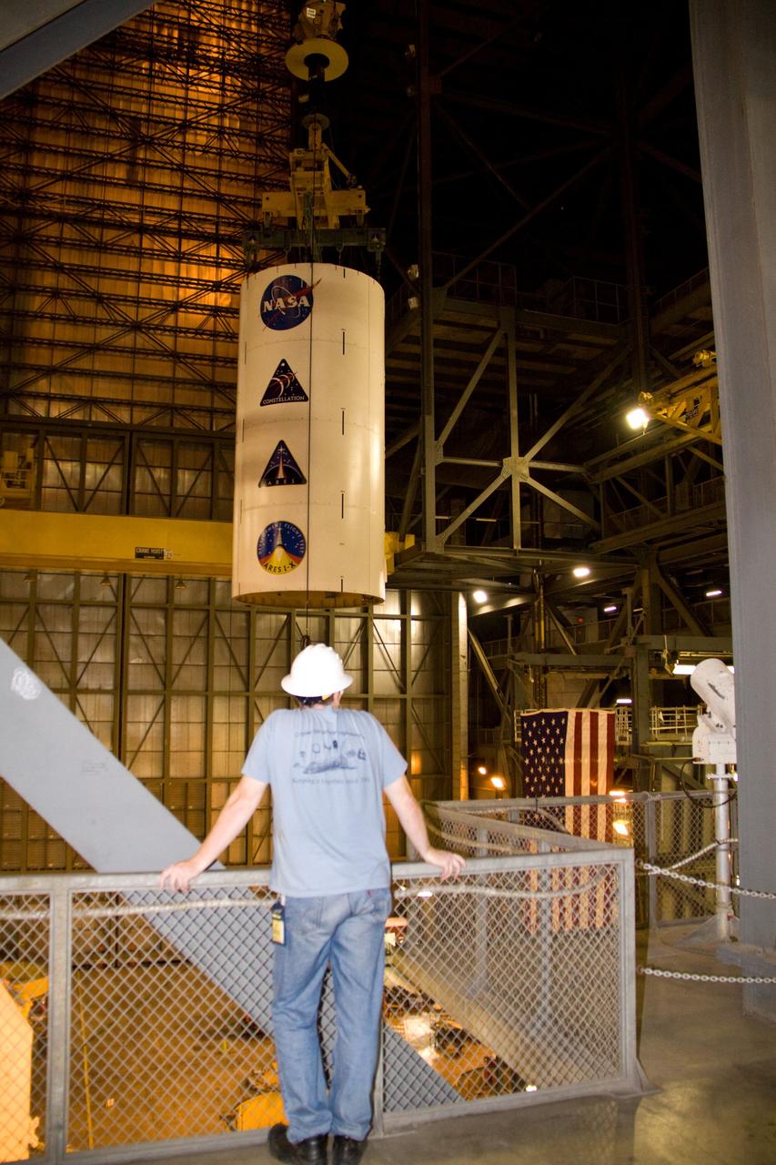
CAPE CANAVERAL, Fla. – In NASA Kennedy Space Center's Vehicle Assembly Building High Bay 3, a crane moves the Ares I-X Super Stack 3 across the transfer aisle to High Bay 4. There it will be integrated with Super Stack 2. The upper stage comprises five super stacks, which are integrated with the four-segment solid rocket booster first stage on the mobile launch platform. Ares I-X is the test vehicle for the Ares I, which is part of the Constellation Program to return men to the moon and beyond. The Ares I-X flight test is targeted for Oct. 31, pending formal NASA Headquarters approval. Photo credit: NASA/Jack Pfaller
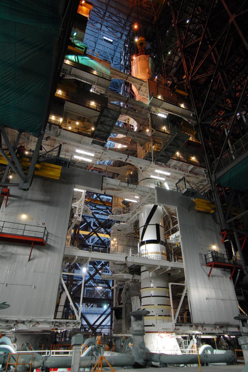
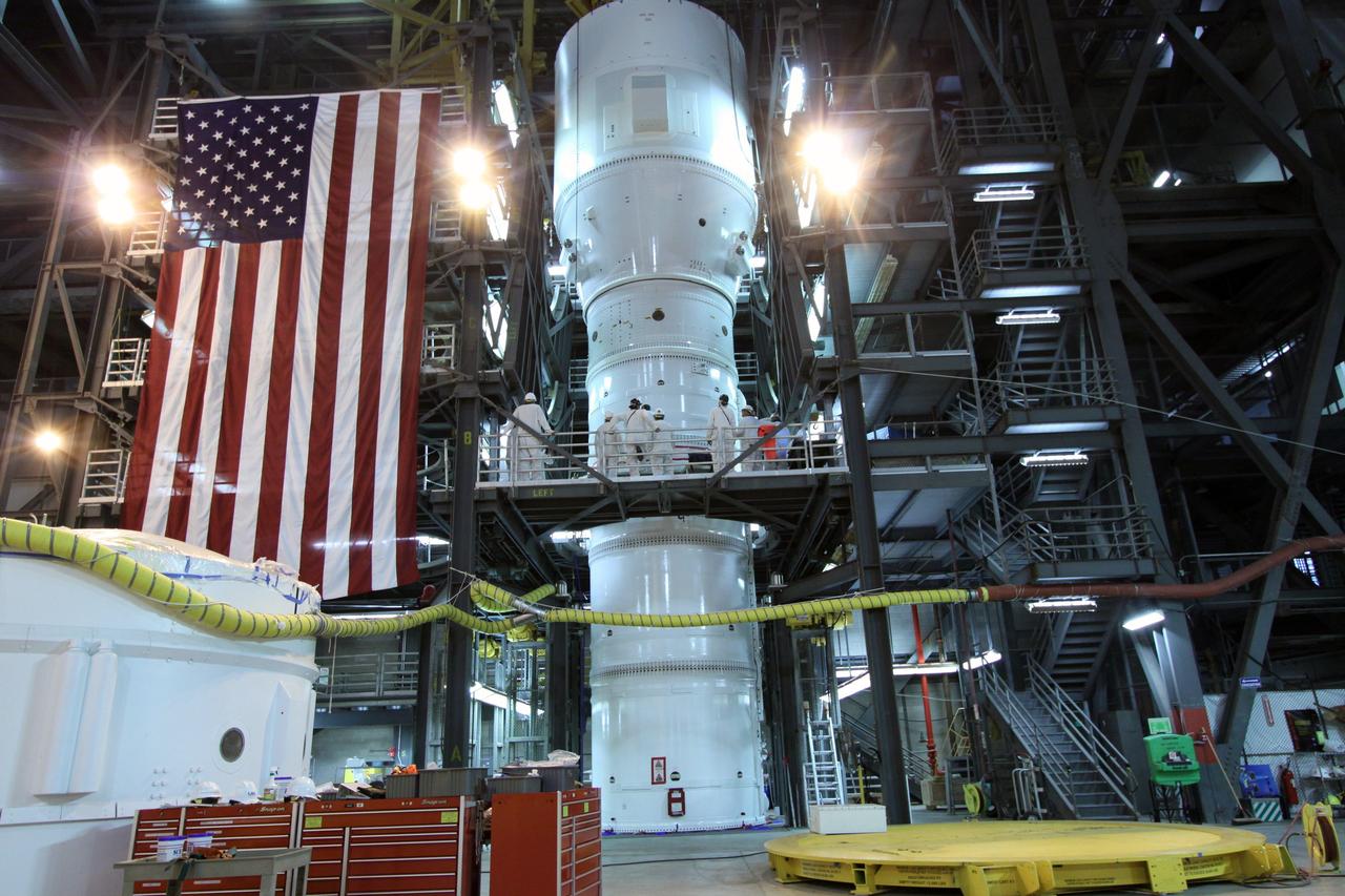
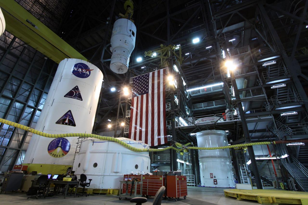
CAPE CANAVERAL, Fla. – In the Vehicle Assembly Building's High Bay 3 at NASA's Kennedy Space Center in Florida, a crane has lowered Super Stack 2, part of the Ares I-X upper stage, onto Super Stack 1 for assembly. The upper stage comprises five super stacks, which are integrated with the four-segment solid rocket booster first stage on the mobile launch platform. Ares I-X is the test vehicle for the Ares I, which is part of the Constellation Program to return men to the moon and beyond. The Ares I-X flight test is targeted for Oct. 31, pending formal NASA Headquarters approval. Photo credit: NASA/Tim Jacobs
CAPE CANAVERAL, Fla. – In the Vehicle Assembly Building's High Bay 3 at NASA's Kennedy Space Center in Florida, a crane has lowered Super Stack 2, part of the Ares I-X upper stage, onto Super Stack 1 for integration atop the first stage, which comprises four solid rocket booster segments, on the mobile launch platform. Ares I-X is the test vehicle for the Ares I, which is part of the Constellation Program to return men to the moon and beyond. The Ares I-X flight test is targeted for Oct. 31, pending formal NASA Headquarters approval. Photo credit: NASA/Tim Jacobs
CAPE CANAVERAL, Fla. – In NASA Kennedy Space Center's Vehicle Assembly Building High Bay 4, a crane lowers the Ares I-X Super Stack 3 onto Super Stack 2 for integration. The upper stage comprises five super stacks, which are integrated with the four-segment solid rocket booster first stage on the mobile launch platform. Ares I-X is the test vehicle for the Ares I, which is part of the Constellation Program to return men to the moon and beyond. The Ares I-X flight test is targeted for Oct. 31, pending formal NASA Headquarters approval. Photo credit: NASA/Jack Pfaller
CAPE CANAVERAL, Fla. – In NASA Kennedy Space Center's Vehicle Assembly Building, a crane lowers the Ares I-X Super Stack 3 into High Bay 4. There it will be integrated with Super Stack 2. The upper stage comprises five super stacks, which are integrated with the four-segment solid rocket booster first stage on the mobile launch platform. Ares I-X is the test vehicle for the Ares I, which is part of the Constellation Program to return men to the moon and beyond. The Ares I-X flight test is targeted for Oct. 31, pending formal NASA Headquarters approval. Photo credit: NASA/Jack Pfaller
CAPE CANAVERAL, Fla. – In the Vehicle Assembly Building at NASA's Kennedy Space Center in Florida, segments of the Ares I-X first stage are mated to the fifth simulator segment, completing Super Stack 1. The super stack comprises the forward skirt, forward skirt extension, interstages 1 and 2 and the fifth segment simulator. Ares I-X is the test vehicle for the Ares I, which is part of the Constellation Program to return men to the moon and beyond. The Ares I-X flight test is targeted no earlier than Aug. 30 from Launch Pad 39B. Photo credit: NASA/Jack Pfaller
CAPE CANAVERAL, Fla. – In NASA Kennedy Space Center's Vehicle Assembly Building High Bay 3, a crane lifts the Ares I-X Super Stack 3 to move it across the transfer aisle to High Bay 4. There it will be integrated with Super Stack 2. The upper stage comprises five super stacks, which are integrated with the four-segment solid rocket booster first stage on the mobile launch platform. Ares I-X is the test vehicle for the Ares I, which is part of the Constellation Program to return men to the moon and beyond. The Ares I-X flight test is targeted for Oct. 31, pending formal NASA Headquarters approval. Photo credit: NASA/Jack Pfaller
CAPE CANAVERAL, Fla. – In the Vehicle Assembly Building at NASA's Kennedy Space Center in Florida, segments of the Ares I-X first stage are moved across the bay. They will be stacked and mated to the fifth segment simulator, completing Super Stack 1. The super stack comprises the forward skirt, forward skirt extension, interstages 1 and 2 and the fifth segment simulator. Ares I-X is the test vehicle for the Ares I, which is part of the Constellation Program to return men to the moon and beyond. The Ares I-X flight test is targeted no earlier than Aug. 30 from Launch Pad 39B. Photo credit: NASA/Jack Pfaller
CAPE CANAVERAL, Fla. – In the Vehicle Assembly Building's High Bay 4, the Ares I-X "super stack 1" is to be lifted into High Bay 3 and attached to the forward motor segment. Super stack 1 comprises the frustum, forward skirt, forward skirt extension, interstages 1 and 2 and the fifth segment simulator. Ares I-X is the test vehicle for the Ares I, which is part of the Constellation Program to return men to the moon and beyond. The Ares I-X flight test is targeted for Oct. 31, pending forma NASA Headquarters approval. Photo credit: NASA/Jack Pfaller
CAPE CANAVERAL, Fla. – In the Vehicle Assembly Building's High Bay 3 at NASA's Kennedy Space Center in Florida, a crane lowers Super Stack 2, part of the Ares I-X upper stage, for attachment with Super Stack 1 below. The upper stage comprises five super stacks, which are integrated with the four-segment solid rocket booster first stage on the mobile launch platform. Ares I-X is the test vehicle for the Ares I, which is part of the Constellation Program to return men to the moon and beyond. The Ares I-X flight test is targeted for Oct. 31, pending formal NASA Headquarters approval. Photo credit: NASA/Tim Jacobs
CAPE CANAVERAL, Fla. – In the Vehicle Assembly Building's High Bay 3 at NASA's Kennedy Space Center in Florida, a crane lowers Super Stack 2, part of the Ares I-X upper stage, onto Super Stack 1 for integration. The upper stage comprises five super stacks, which are integrated with the four-segment solid rocket booster first stage on the mobile launch platform. Ares I-X is the test vehicle for the Ares I, which is part of the Constellation Program to return men to the moon and beyond. The Ares I-X flight test is targeted for Oct. 31, pending formal NASA Headquarters approval. Photo credit: NASA/Tim Jacobs
CAPE CANAVERAL, Fla. – In the Vehicle Assembly Building at NASA's Kennedy Space Center in Florida, segments of the Ares I-X first stage are lowered toward the fifth simulator segment for mating, to complete Super Stack 1. The super stack comprises the forward skirt, forward skirt extension, interstages 1 and 2 and the fifth segment simulator. Ares I-X is the test vehicle for the Ares I, which is part of the Constellation Program to return men to the moon and beyond. The Ares I-X flight test is targeted no earlier than Aug. 30 from Launch Pad 39B. Photo credit: NASA/Jack Pfaller
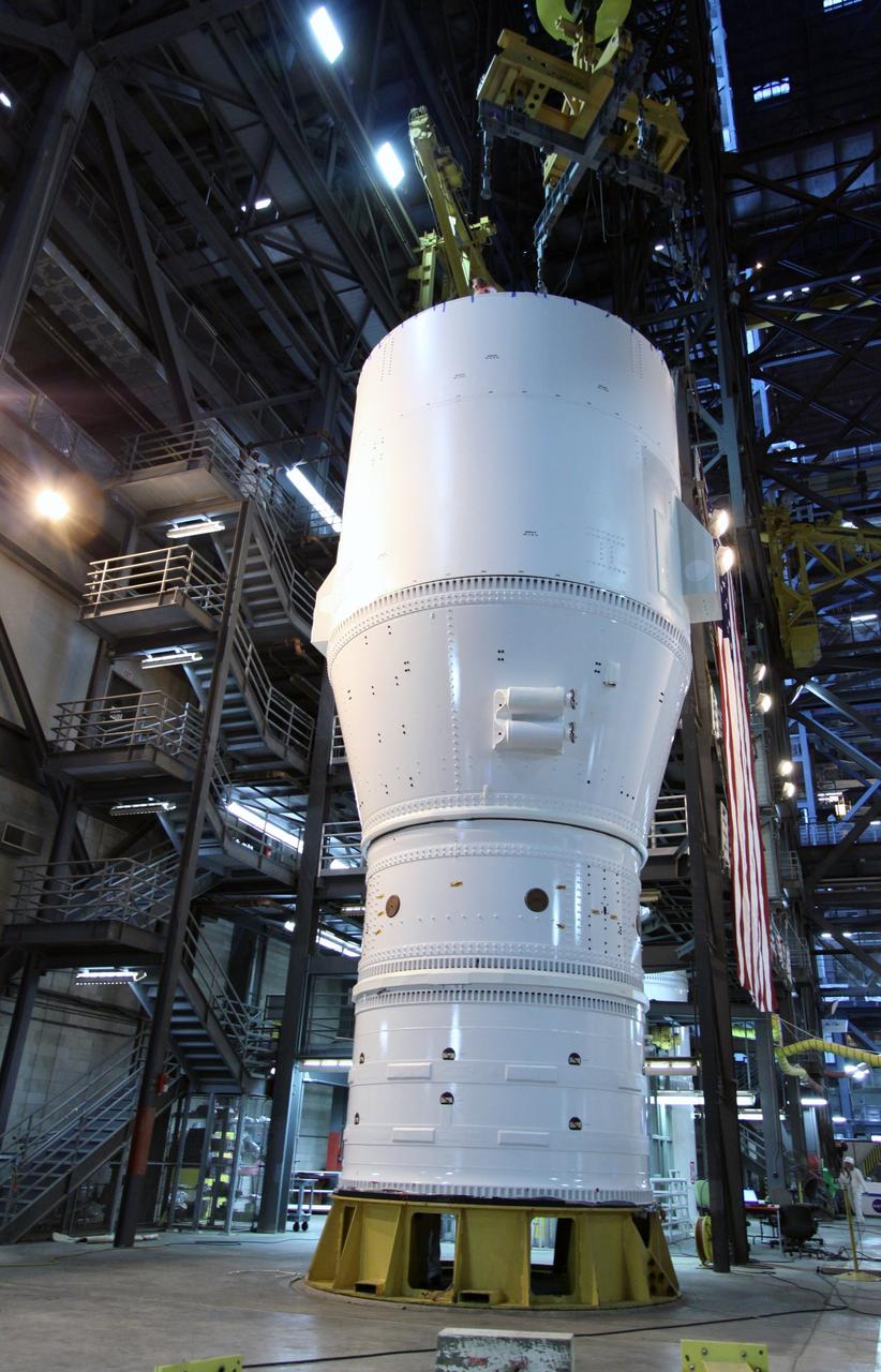
CAPE CANAVERAL, Fla. – In the Vehicle Assembly Building at NASA's Kennedy Space Center in Florida, segments of the Ares I-X first stage are fitted with a crane to lift it to the fifth segment simulator for mating, completing Super Stack 1. The super stack comprises the forward skirt, forward skirt extension, interstages 1 and 2 and the fifth segment simulator. Ares I-X is the test vehicle for the Ares I, which is part of the Constellation Program to return men to the moon and beyond. The Ares I-X flight test is targeted no earlier than Aug. 30 from Launch Pad 39B. Photo credit: NASA/Jack Pfaller
CAPE CANAVERAL, Fla. – In the Vehicle Assembly Building at NASA's Kennedy Space Center in Florida, segments of the Ares I-X first stage move past other stacks toward the fifth simulator segment stack at right. The two stacks will be mated, completing Super Stack 1. The super stack comprises the forward skirt, forward skirt extension, interstages 1 and 2 and the fifth segment simulator. Ares I-X is the test vehicle for the Ares I, which is part of the Constellation Program to return men to the moon and beyond. The Ares I-X flight test is targeted no earlier than Aug. 30 from Launch Pad 39B. Photo credit: NASA/Jack Pfaller
CAPE CANAVERAL, Fla. – In the Vehicle Assembly Building at NASA's Kennedy Space Center in Florida, segments of the Ares I-X first stage are lifted from the stand. The segments are being moved for stacking and mating to the fifth segment simulator, completing Super Stack 1. The super stack comprises the forward skirt, forward skirt extension, interstages 1 and 2 and the fifth segment simulator. Ares I-X is the test vehicle for the Ares I, which is part of the Constellation Program to return men to the moon and beyond. The Ares I-X flight test is targeted no earlier than Aug. 30 from Launch Pad 39B. Photo credit: NASA/Jack Pfaller
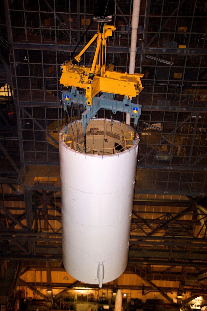
CAPE CANAVERAL, Fla. – In NASA Kennedy Space Center's Vehicle Assembly Building High Bay 3, a crane moves the Ares I-X Super Stack 3 across the transfer aisle to High Bay 4. There it will be integrated with Super Stack 2. The upper stage comprises five super stacks, which are integrated with the four-segment solid rocket booster first stage on the mobile launch platform. Ares I-X is the test vehicle for the Ares I, which is part of the Constellation Program to return men to the moon and beyond. The Ares I-X flight test is targeted for Oct. 31, pending formal NASA Headquarters approval. Photo credit: NASA/Jack Pfaller
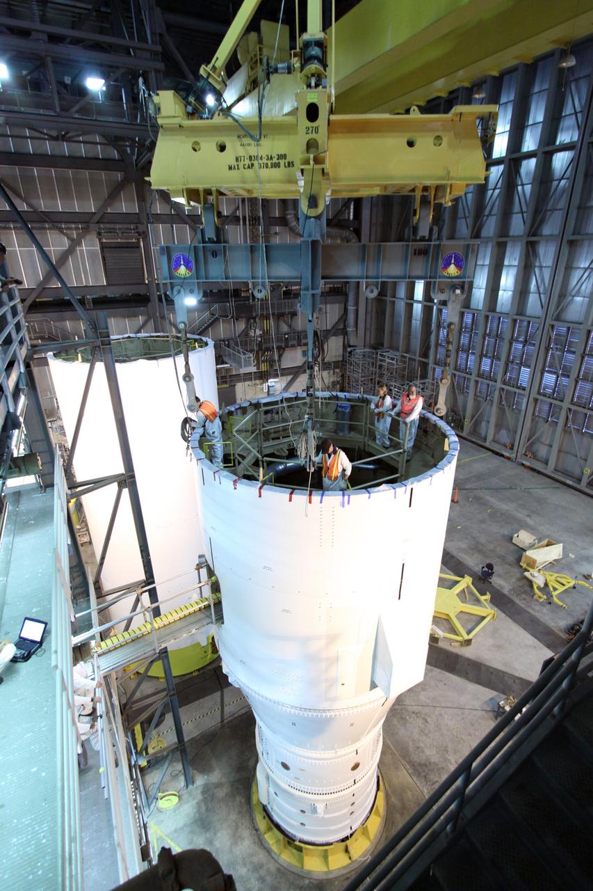
CAPE CANAVERAL, Fla. – In the Vehicle Assembly Building at NASA's Kennedy Space Center in Florida, the segments of the Ares I-X first stage are fitted with a crane to lift it to the fifth segment simulator for mating, completing Super Stack 1. The super stack comprises the forward skirt, forward skirt extension, interstages 1 and 2 and the fifth segment simulator. Ares I-X is the test vehicle for the Ares I, which is part of the Constellation Program to return men to the moon and beyond. The Ares I-X flight test is targeted no earlier than Aug. 30 from Launch Pad 39B. Photo credit: NASA/Jack Pfaller
CAPE CANAVERAL, Fla. – In the Vehicle Assembly Building's High Bay 3 at NASA's Kennedy Space Center in Florida, a crane lowers Super Stack 2, part of the Ares I-X upper stage, for integration with Super Stack 1. The upper stage comprises five super stacks, which are integrated with the four-segment solid rocket booster first stage on the mobile launch platform. Ares I-X is the test vehicle for the Ares I, which is part of the Constellation Program to return men to the moon and beyond. The Ares I-X flight test is targeted for Oct. 31, pending formal NASA Headquarters approval. Photo credit: NASA/Tim Jacobs
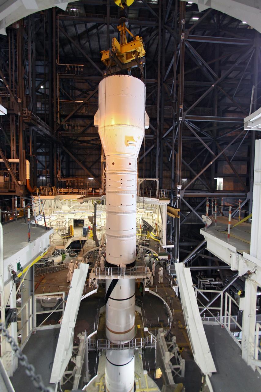
CAPE CANAVERAL, Fla. – In the Vehicle Assembly Building's High Bay 3, the Ares I-X "super stack 1" is being attached to the forward motor segment. Super stack 1 comprises the frustum, forward skirt, forward skirt extension, interstages 1 and 2 and the fifth segment simulator. Ares I-X is the test vehicle for the Ares I, which is part of the Constellation Program to return men to the moon and beyond. The Ares I-X flight test is targeted for Oct. 31, pending forma NASA Headquarters approval. Photo credit: NASA/Jack Pfaller
CAPE CANAVERAL, Fla. – In the Vehicle Assembly Building's High Bay 3 at NASA's Kennedy Space Center in Florida, a crane lowers Super Stack 2, part of the Ares I-X upper stage, onto Super Stack 1 for integration. The upper stage comprises five super stacks, which are integrated with the four-segment solid rocket booster first stage on the mobile launch platform. Ares I-X is the test vehicle for the Ares I, which is part of the Constellation Program to return men to the moon and beyond. The Ares I-X flight test is targeted for Oct. 31, pending formal NASA Headquarters approval. Photo credit: NASA/Tim Jacobs
CAPE CANAVERAL, Fla. – In NASA Kennedy Space Center's Vehicle Assembly Building, a crane is attached to the Ares I-X Super Stack 3 in High Bay 3. The stack is being moved to High Bay 4 for integration with Super Stack 2. The upper stage comprises five super stacks, which are integrated with the four-segment solid rocket booster first stage on the mobile launch platform. Ares I-X is the test vehicle for the Ares I, which is part of the Constellation Program to return men to the moon and beyond. The Ares I-X flight test is targeted for Oct. 31, pending formal NASA Headquarters approval. Photo credit: NASA/Jack Pfaller

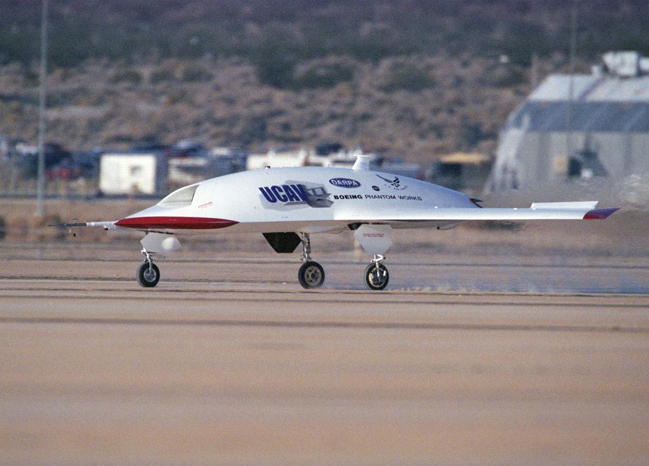
The second X-45A Unmanned Combat Air Vehicle (UCAV) technology demonstrator completed its first flight on November 21, 2002, after taking off from a dry lakebed at NASA's Dryden Flight Research Center, Edwards Air Force Base, California. X-45A vehicle two flew for approximately 30 minutes and reached an airspeed of 195 knots and an altitude of 7500 feet. This flight validated the functionality of the UCAV flight software on the second air vehicle. Dryden is supporting the DARPA/Boeing team in the design, development, integration, and demonstration of the critical technologies, processes, and system attributes leading to an operational UCAV system. Dryden support of the X-45A demonstrator system includes analysis, component development, simulations, ground and flight tests.
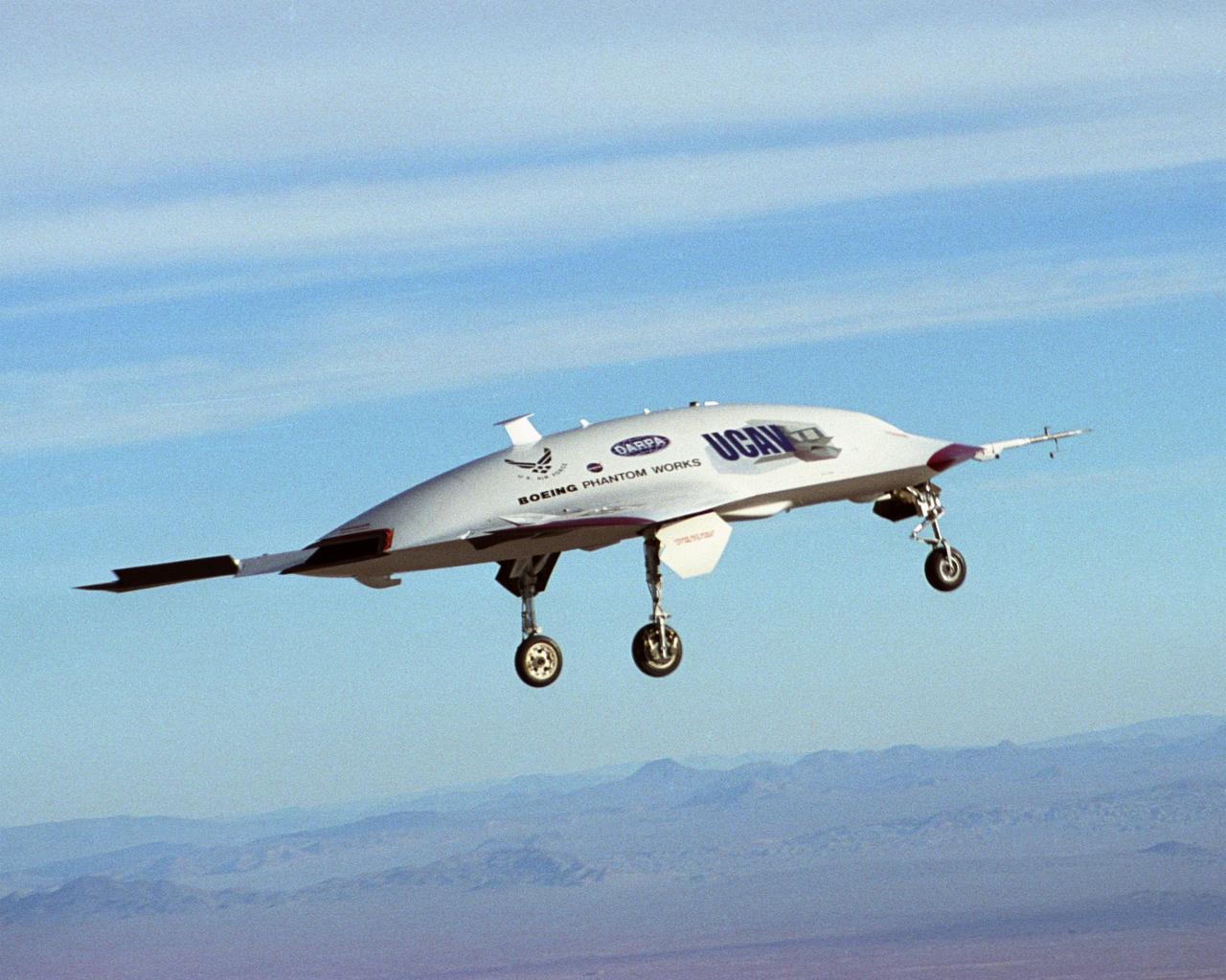
The second X-45A Unmanned Combat Air Vehicle (UCAV) technology demonstrator completed its first flight on November 21, 2002, after taking off from a dry lakebed at NASA's Dryden Flight Research Center, Edwards Air Force Base, California. X-45A vehicle two flew for approximately 30 minutes and reached an airspeed of 195 knots and an altitude of 7500 feet. This flight validated the functionality of the UCAV flight software on the second air vehicle. Dryden is supporting the DARPA/Boeing team in the design, development, integration, and demonstration of the critical technologies, processes, and system attributes leading to an operational UCAV system. Dryden support of the X-45A demonstrator system includes analysis, component development, simulations, ground and flight tests.
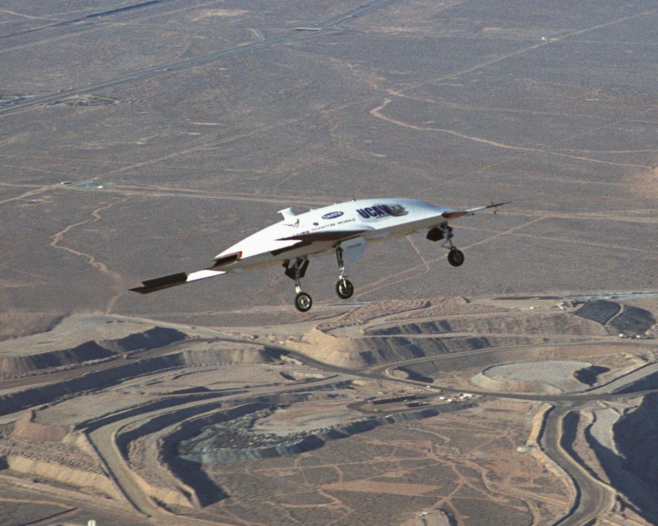
The second X-45A Unmanned Combat Air Vehicle (UCAV) technology demonstrator completed its first flight on November 21, 2002, after taking off from a dry lakebed at NASA's Dryden Flight Research Center, Edwards Air Force Base, California. X-45A vehicle two flew for approximately 30 minutes and reached an airspeed of 195 knots and an altitude of 7500 feet. This flight validated the functionality of the UCAV flight software on the second air vehicle. Dryden is supporting the DARPA/Boeing team in the design, development, integration, and demonstration of the critical technologies, processes, and system attributes leading to an operational UCAV system. Dryden support of the X-45A demonstrator system includes analysis, component development, simulations, ground and flight tests.
The second X-45A Unmanned Combat Air Vehicle (UCAV) technology demonstrator completed its first flight on November 21, 2002, after taking off from a dry lakebed at NASA's Dryden Flight Research Center, Edwards Air Force Base, California. X-45A vehicle two flew for approximately 30 minutes and reached an airspeed of 195 knots and an altitude of 7500 feet. This flight validated the functionality of the UCAV flight software on the second air vehicle. Dryden is supporting the DARPA/Boeing team in the design, development, integration, and demonstration of the critical technologies, processes, and system attributes leading to an operational UCAV system. Dryden support of the X-45A demonstrator system includes analysis, component development, simulations, ground and flight tests.