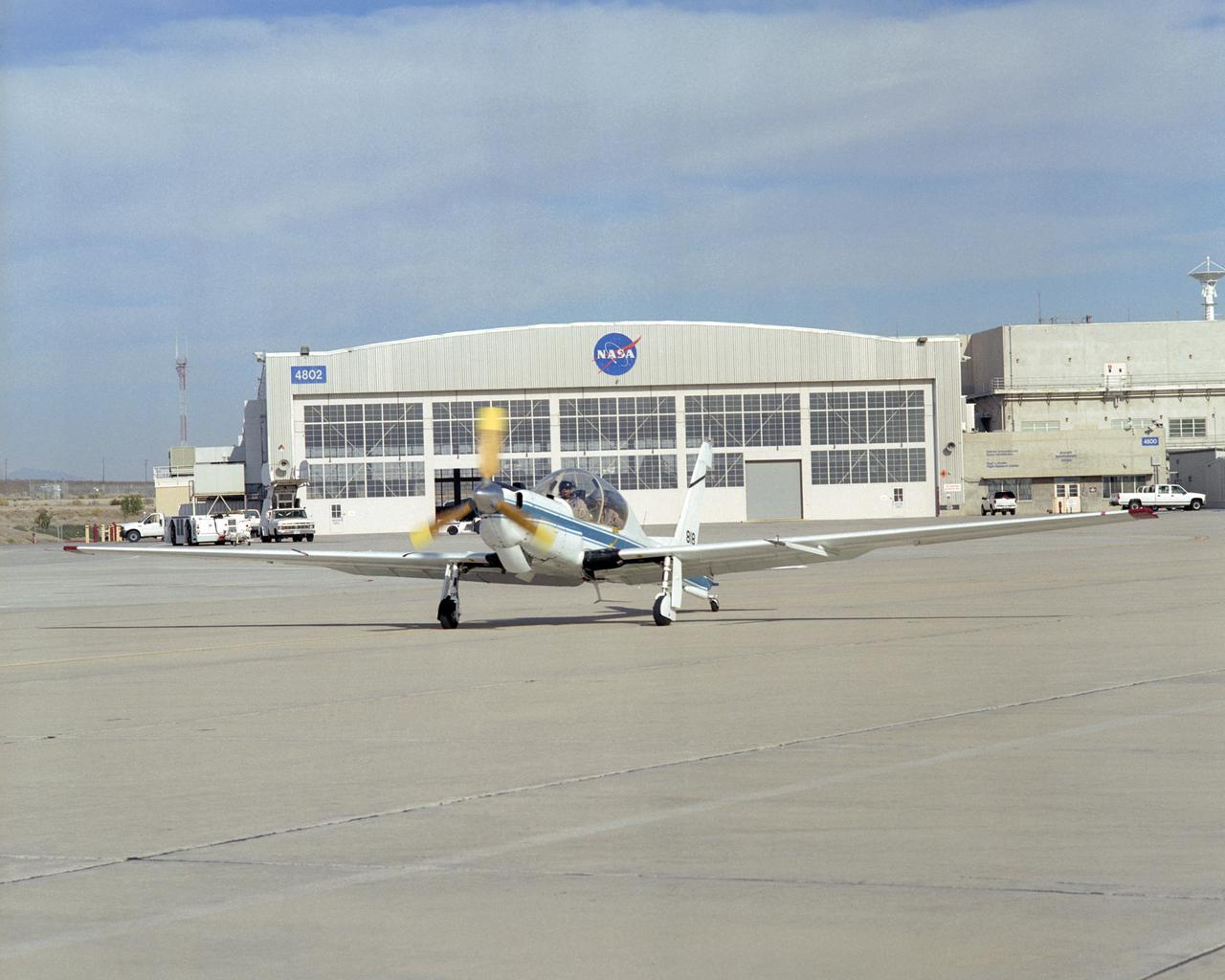
NASA's ultra-quiet YO-3A acoustics research aircraft taxis out from the ramp at the Dryden Flight Research Center before a pilot checkout flight.
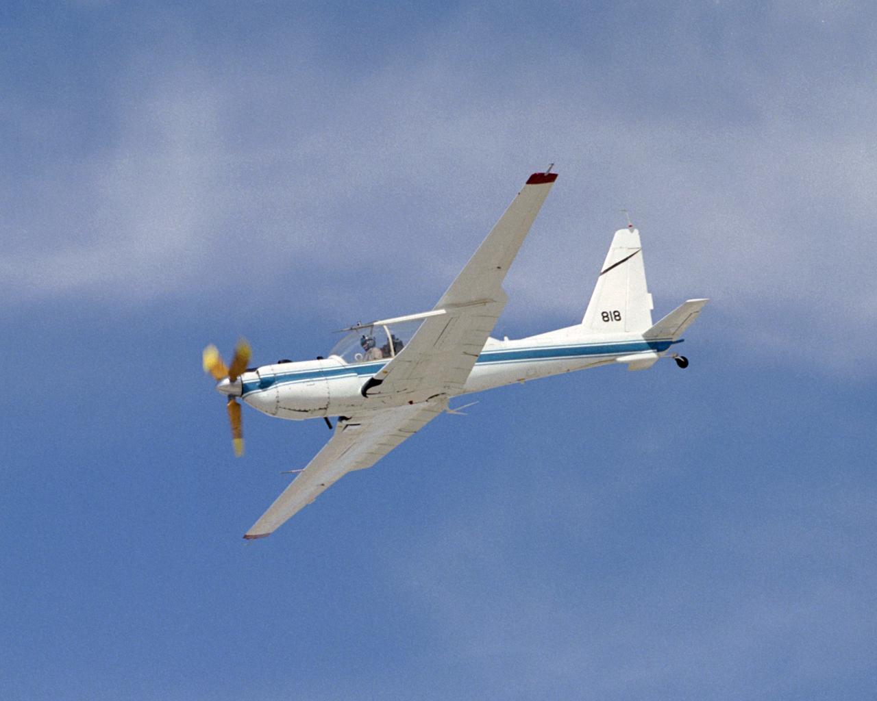
The slow-speed wooden propeller and long wings are evident as NASA's YO-3A acoustics research aircraft performs a low-level flyover at Edwards Air Force Base.
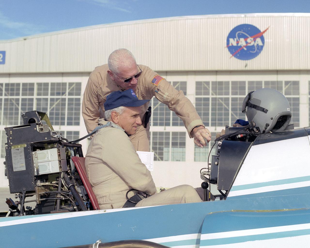
NASA pilot Ed Lewis (rear) briefs NASA test pilot Dick Ewers on the flight instruments of NASA's YO-3A acoustics research aircraft prior to a checkout flight.
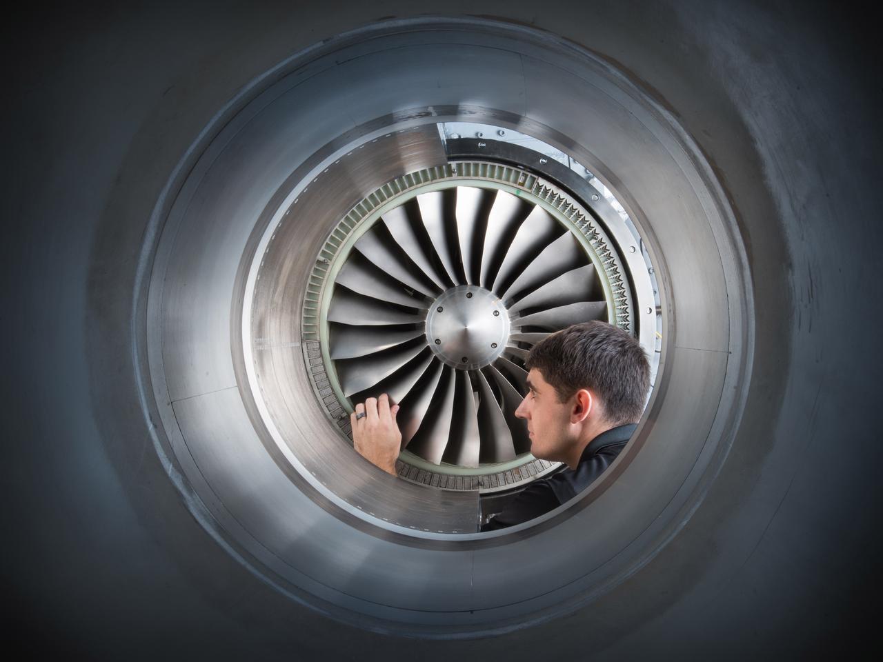
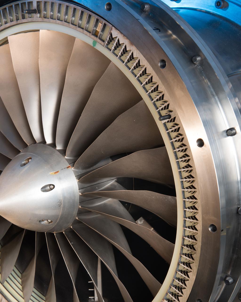
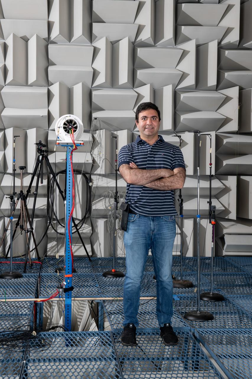
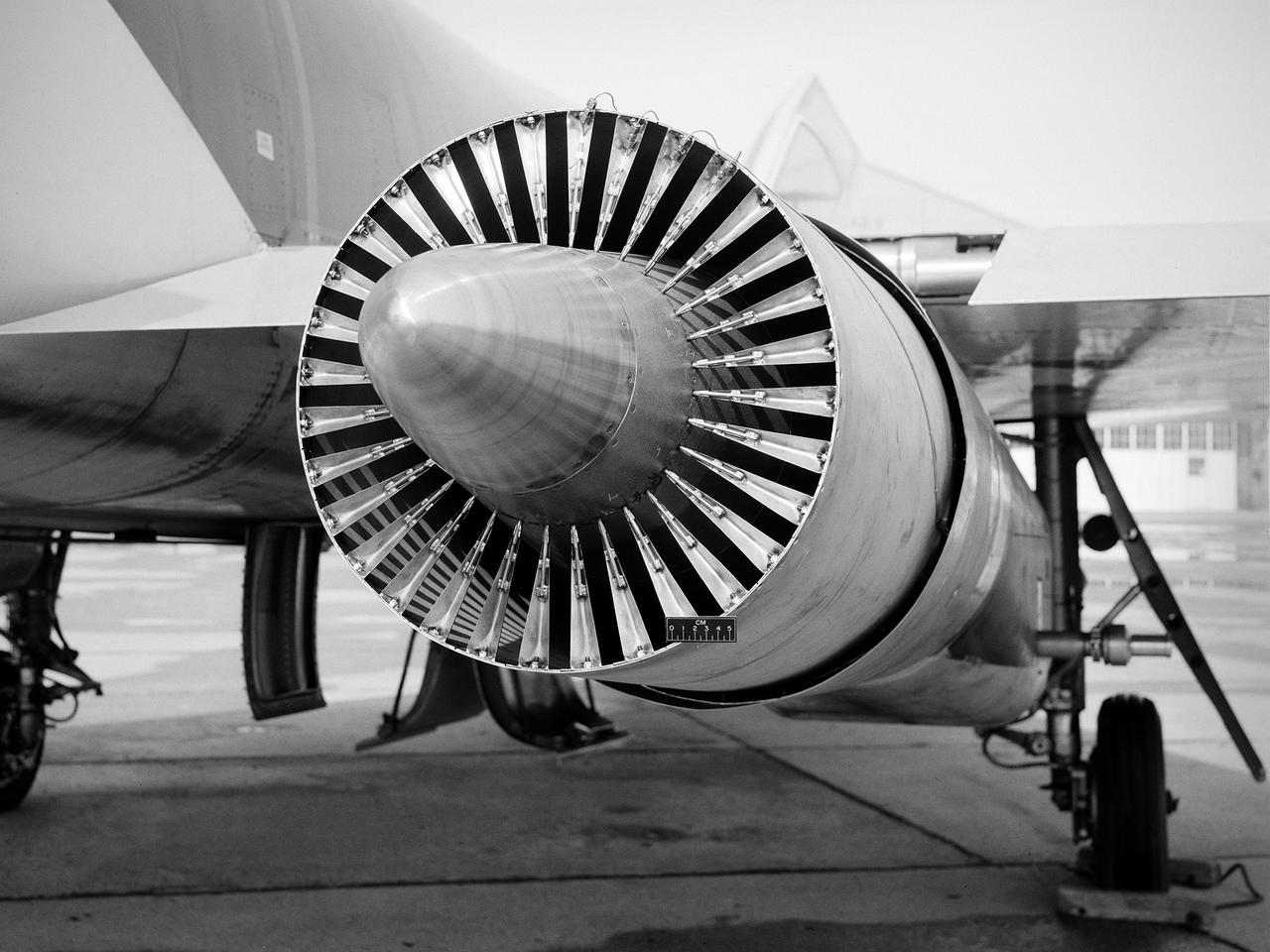
Acoustic Casing Treatment Testing Completed in the W-8 Single Stage Axial Compressor Facility at NASA Glenn. Four different over-the-rotor acoustic casing treatment concepts were tested along with two baseline configurations. Testing included steady-aerodynamic measurements of fan performance, hotfilm turbulence measurements, and inlet acoustic measurements with an in-duct array.
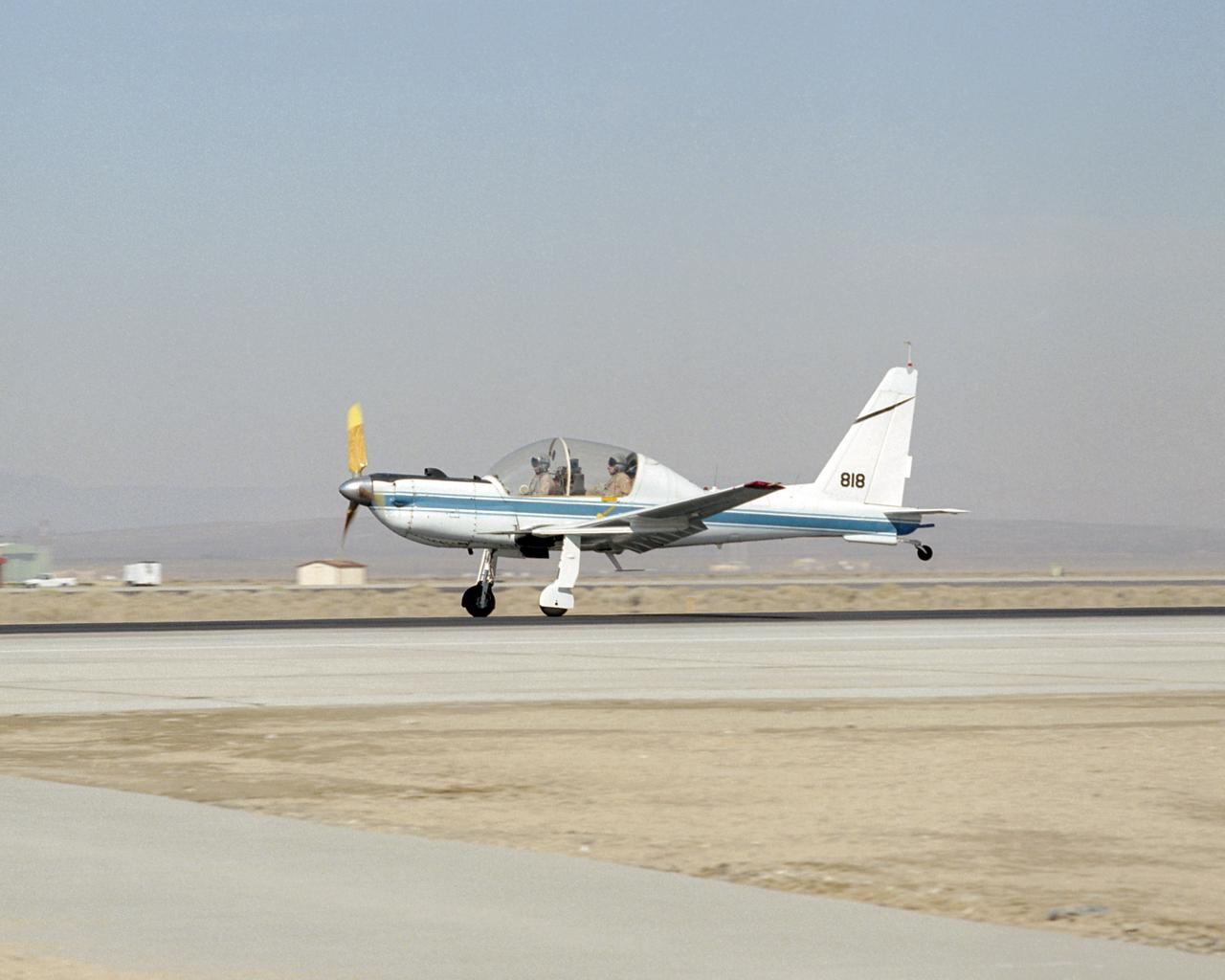
NASA's converted YO-3A observation plane, now used for acoustics research, touches down at Edwards Air Force Base following a pilot checkout flight.
Acoustic Casing Treatment Testing Completed in the W-8 Single Stage Axial Compressor Facility at NASA Glenn. Four different over-the-rotor acoustic casing treatment concepts were tested along with two baseline configurations. Testing included steady-aerodynamic measurements of fan performance, hotfilm turbulence measurements, and inlet acoustic measurements with an in-duct array.
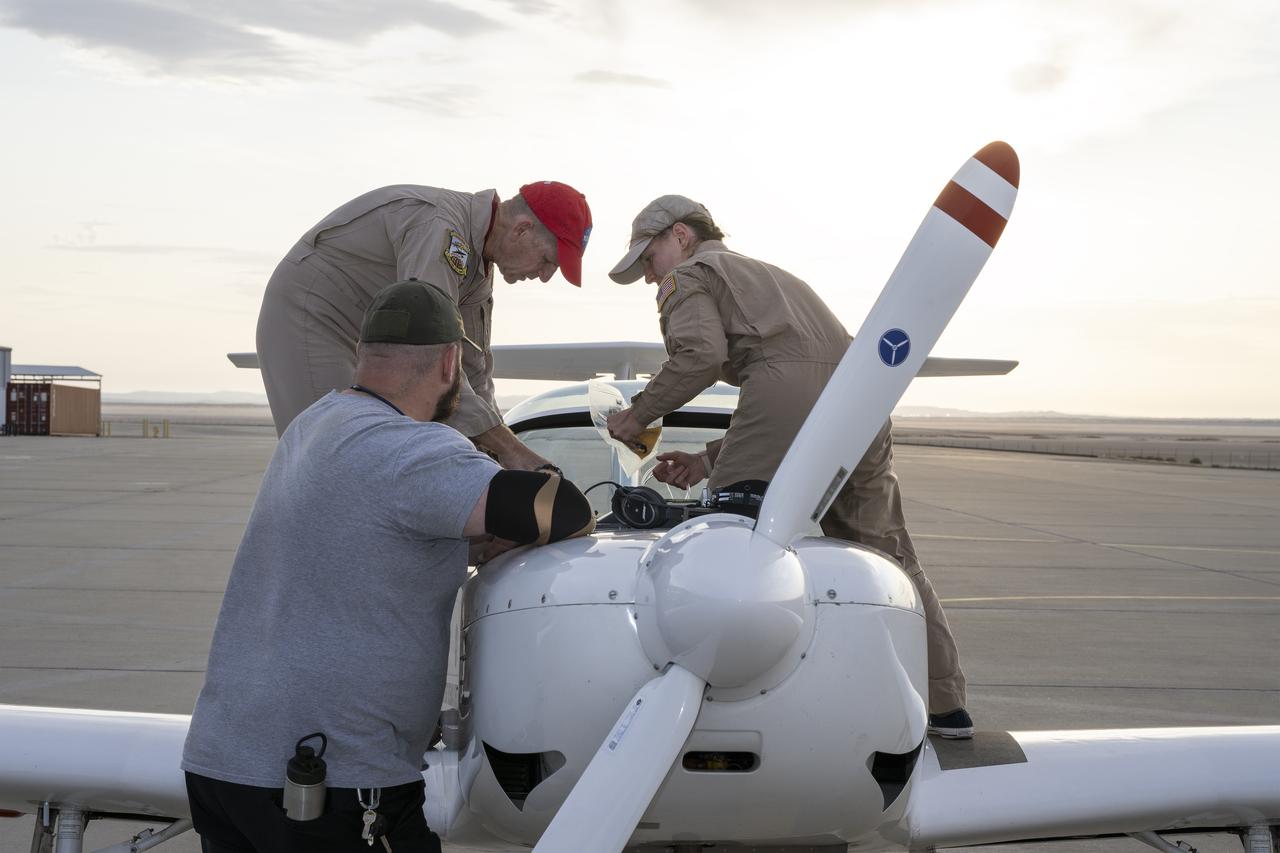
A NASA TG-14 glider aircraft is prepared for flight at NASA’s Armstrong Flight Research Center in Edwards, California, in support of the agency’s Quesst mission. The aircraft is equipped with onboard microphones to capture sonic boom noise generated during rehearsal flights, helping researchers measure the acoustic signature of supersonic aircraft closer to the ground.
Claudia Sales, NASA’s acting X-59 deputy chief engineer and airworthiness certification lead for the quiet supersonic research aircraft, supports ground testing for Acoustic Research Measurements (ARM) flights. The test campaign to evaluate technologies that reduce aircraft noise was conducted at NASA’s Armstrong Flight Research Center in Edwards, California, in 2018.
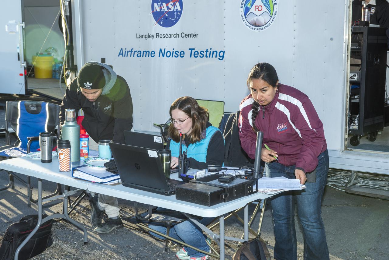
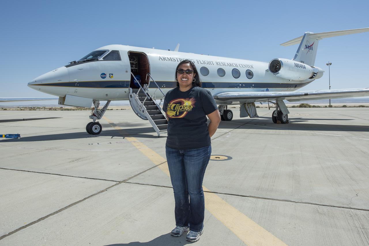
Claudia Sales, NASA’s acting X-59 deputy chief engineer and airworthiness certification lead for the quiet supersonic research aircraft, stands in front of a Gulfstream G-III, also known as Subsonic Research Aircraft Testbed (SCRAT). Sales supported ground testing as test conductor for Acoustics Research Measurements (ARM) flights at NASA’s Armstrong Research Flight Center in Edwards, California, in 2018.
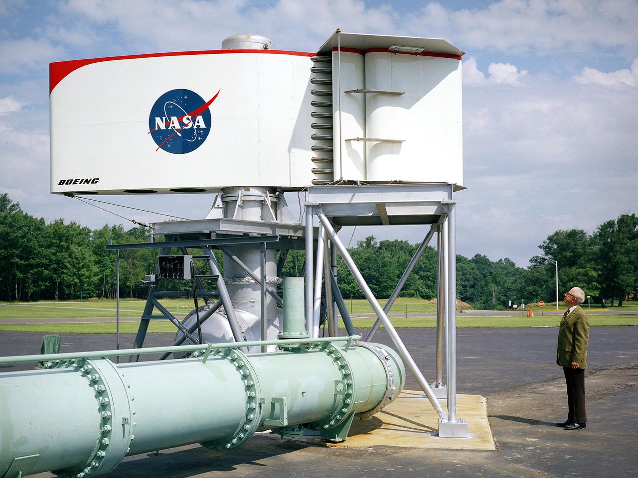
The augmentor wing concept was introduced during the early 1960s to enhance the performance of vertical and short takeoff (VSTOL) aircraft. The leading edge of the wing has full-span vertical flaps, and the trailing edge has double-slotted flaps. This provides aircraft with more control in takeoff and landing conditions. The augmentor wing also produced lower noise levels than other VSTOL designs. In the early 1970s Boeing Corporation built a Buffalo C-8A augmentor wing research aircraft for Ames Research Center. Researches at Lewis Research Center concentrated their efforts on reducing the noise levels of the wing. They initially used small-scale models to develop optimal nozzle screening methods. They then examined the nozzle designs on a large-scale model, seen here on an external test stand. This test stand included an airflow system, nozzle, the augmentor wing, and a muffler system below to reduce the atmospheric noise levels. The augmentor was lined with noise-reducing acoustic panels. The Lewis researchers were able to adjust the airflow to simulate conditions at takeoff and landing. Once the conditions were stabilized they took noise measurements from microphones placed in all directions from the wing, including an aircraft flying over. They found that the results coincided with the earlier small-scale studies for landing situations but not takeoffs. The acoustic panels were found to be successful.
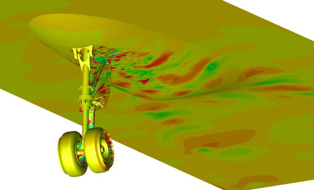
Snapshot from a simulation run on the Pleiades supercomputer. It depicts a fluctuating pressure field on aircraft nose landing gear and fuselage surfaces. The simulation helped scientists better understand the effects of landing gear and acoustic noise. The goal of the study was to improve the current understanding of aircraft nose landing gear noise, which will lead to quieter, more efficient airframe components for future aircraft designs. The visualization was produced with help from the NAS Data Analysis & Visualization group. Investigator: Mehdi Khorrami, NASA Langley Research Center.

Title: W-8 Fan Acoustic Casing Treatment Test on the Source Diagnostic Test Rotor Alone Hardware Program: Advanced Air Vehicles Program (AAVP) Project: Advanced Air Transport Technology (AATT) Sub-project: Aircraft Noise Reduction (ANR) Weekly Highlight: · Acoustic Casing Treatment Testing Completed in the W-8 Single Stage Axial Compressor Facility: Testing of Acoustic Casing Treatments on the Source Diagnostic Test (SDT) rotor alone hardware which had begun in early January was completed on Thursday, February 16th. Four different over-the-rotor acoustic casing treatment concepts were tested along with two baseline configurations. Testing included steady-aerodynamic measurements of fan performance, hotfilm turbulence measurements, and inlet acoustic measurements with an in-duct array. These measurements will be used to assess the aerodynamic and acoustic impact of fan acoustic casing treatments on a high bypass ratio fan at TRL 3. This test was the last of 3 planned tests of potential over-the-rotor acoustic casing treatments. The first treatment test was completed in the Normal Incidence Tube (NIT) at Langley Research Center (LaRC) in Fall 2015 and the second was completed on the Advanced Noise Control Fan (ANCF) in the Aero-Acoustic Propulsion Laboratory (AAPL) in Winter 2016. This work is supported by the Aircraft Noise Reduction (ANR) subproject of the Advanced Air Transport Technology (AATT) Project. (POC: LTV/ Rick Bozak 3-5160)
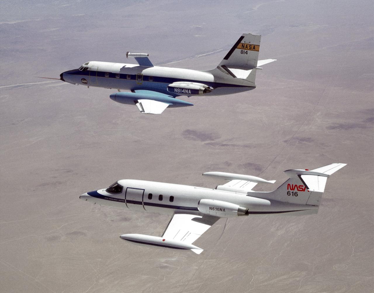
The NASA C-140 JetStar research aircraft (top) is followed by a NASA Learjet equipped with acoustic sensors during one of several tests of advanced propellors mounted on the vertical pylon atop the JetStar's fuselage. Several advanced prop designs were tested on the JetStar in 1982 by NASA's Dryden Flight Research Facility (DFRF), Edwards, California, to study the effects of noise created by propellors on aircraft structures and cabin interiors. To assess possible noise problems with the subscale turbofan, DFRF technicians mounted microphones on both the JetStar and the Learjet chase plane. DFRF then made measurements at close range and at longer distances. The data enabled structural changes and flightpath modifications.
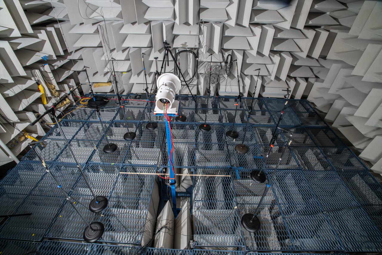
The Quiet Electric Engine V1 (QUEEN V1) experiment that was performed in the NASA GRC Acoustical Testing Laboratory (ATL). Equipment is installed in the anechoic chamber and in the adjacent control room. In response to the pervasive health and environmental problems associated with aviation noise and air pollution, NASA’s Quiet Electric Engine (QUEEN) team is working to increase the peace and quiet in the world by researching ways to make engines for large single-aisle aircraft safer, cleaner, and quieter.

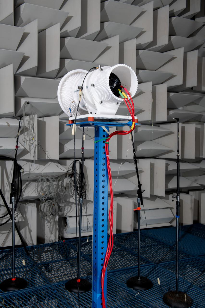
The Quiet Electric Engine V1 (QUEEN V1) experiment that was performed in the NASA GRC Acoustical Testing Laboratory (ATL). Equipment is installed in the anechoic chamber and in the adjacent control room. In response to the pervasive health and environmental problems associated with aviation noise and air pollution, NASA’s Quiet Electric Engine (QUEEN) team is working to increase the peace and quiet in the world by researching ways to make engines for large single-aisle aircraft safer, cleaner, and quieter.
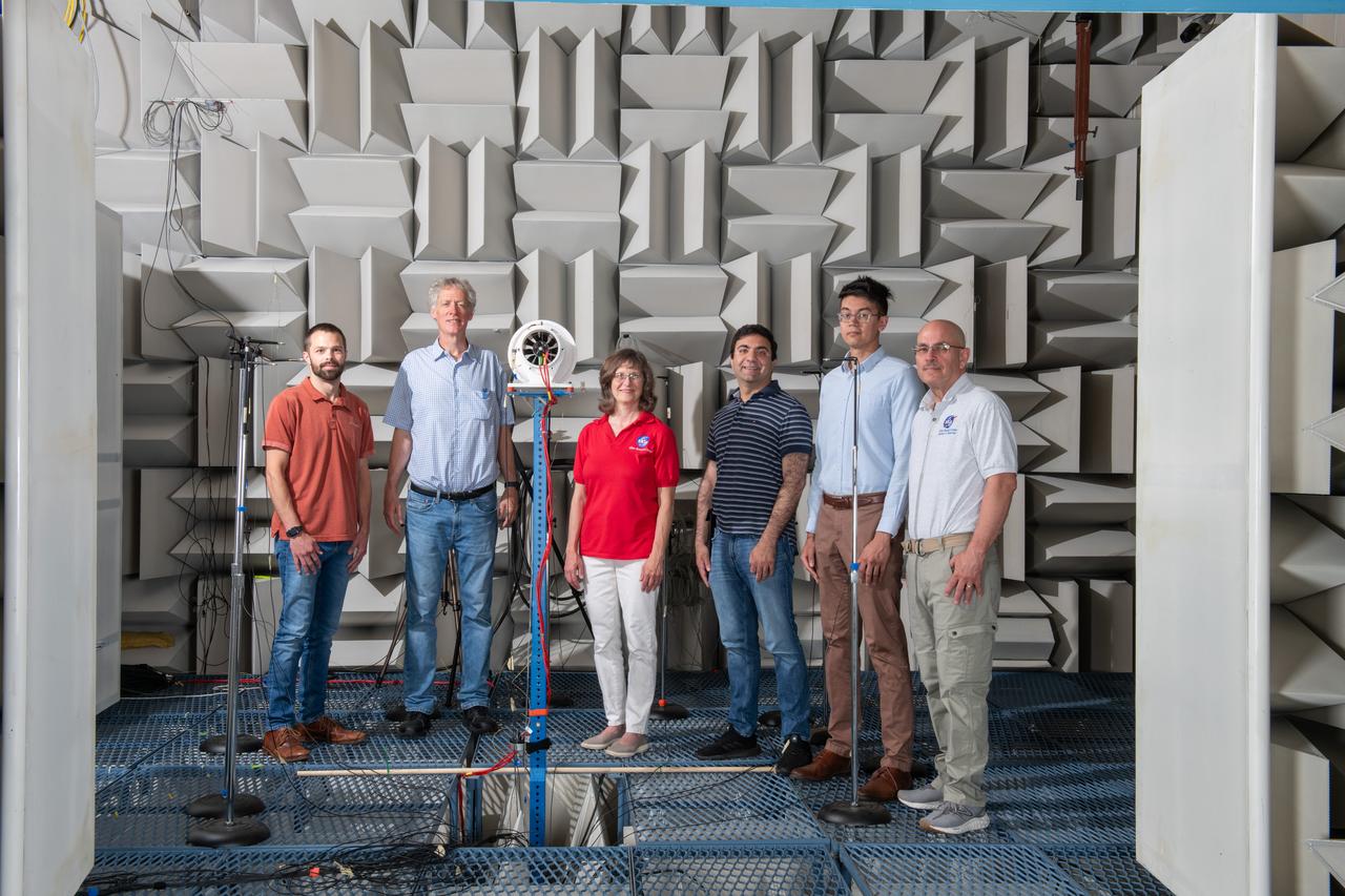
The Quiet Electric Engine V1 (QUEEN V1) experiment that was performed in the NASA GRC Acoustical Testing Laboratory (ATL). Equipment is installed in the anechoic chamber and in the adjacent control room. In response to the pervasive health and environmental problems associated with aviation noise and air pollution, NASA’s Quiet Electric Engine (QUEEN) team is working to increase the peace and quiet in the world by researching ways to make engines for large single-aisle aircraft safer, cleaner, and quieter.

A NASA F/A-18 is towed to the apron at NASA's Armstrong Flight Research Center in Edwards, California during sunrise over Rogers Dry Lake. The F/A-18 was used to test a transmitter for an air navigation system, called the Airborne Location Integrating Geospatial Navigation System, or ALIGNS. This system, designed to allow pilots to position their aircraft at precise distances to each other, will be critical for acoustic validation efforts of NASA's next supersonic X-plane, the X-59 Quiet SuperSonic Technology.
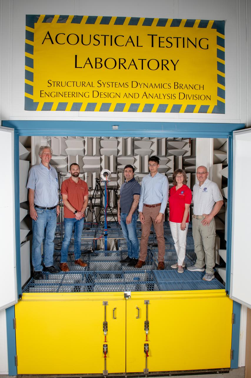
The Quiet Electric Engine V1 (QUEEN V1) experiment that was performed in the NASA GRC Acoustical Testing Laboratory (ATL). Equipment is installed in the anechoic chamber and in the adjacent control room. In response to the pervasive health and environmental problems associated with aviation noise and air pollution, NASA’s Quiet Electric Engine (QUEEN) team is working to increase the peace and quiet in the world by researching ways to make engines for large single-aisle aircraft safer, cleaner, and quieter.
The Quiet Electric Engine V1 (QUEEN V1) experiment that was performed in the NASA GRC Acoustical Testing Laboratory (ATL). Equipment is installed in the anechoic chamber and in the adjacent control room. In response to the pervasive health and environmental problems associated with aviation noise and air pollution, NASA’s Quiet Electric Engine (QUEEN) team is working to increase the peace and quiet in the world by researching ways to make engines for large single-aisle aircraft safer, cleaner, and quieter.
The Quiet Electric Engine V1 (QUEEN V1) experiment that was performed in the NASA GRC Acoustical Testing Laboratory (ATL). Equipment is installed in the anechoic chamber and in the adjacent control room. In response to the pervasive health and environmental problems associated with aviation noise and air pollution, NASA’s Quiet Electric Engine (QUEEN) team is working to increase the peace and quiet in the world by researching ways to make engines for large single-aisle aircraft safer, cleaner, and quieter. Posing with the experiment is aerospace engineer, Jonathan M. Goodman.
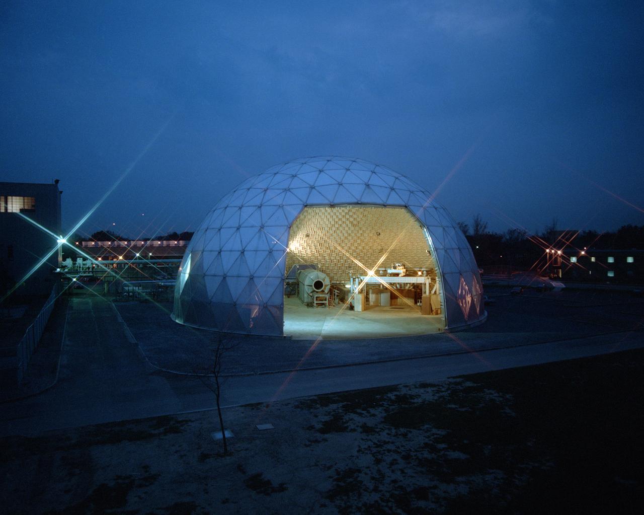
Modern jet engines are loud, but they used to be much louder. NASA’s Glenn Research Center has been at the forefront of the nation’s efforts to reduce aircraft engine noise for over 70 years. During this time, the center has built an array of test facilities to carry out this work, culminating in the Aero-Acoustic Propulsion Laboratory (AAPL), a world-class noise-reduction research facility. The AAPL, referred to as “the dome,” contains multiple test rigs enclosed in a large, echo-free chamber. The unique 130-foot diameter and 65-foot-high hemispherical structure stands out on Glenn’s campus. Its triangular sections make it appear like a golf ball rising from the ground. The interior is covered in spiky, fiberglass sound-dampening wedges and an overhead array of microphones that capture engine noise data.

National Aeronautics and Space Administration (NASA) researcher John Carpenter inspects an aircraft model with a four-fan thrust reverser which would be studied in the 9- by 15-Foot Low Speed Wind Tunnel at the Lewis Research Center. Thrust reversers were introduced in the 1950s as a means for slowing high-speed jet aircraft during landing. Engineers sought to apply the technology to Vertical and Short Takeoff and Landing (VSTOL) aircraft in the 1970s. The new designs would have to take into account shorter landing areas, noise levels, and decreased thrust levels. A balance was needed between the thrust reverser’s efficiency, its noise generation, and the engine’s power setting. This model underwent a series of four tests in the 9- by 15-foot tunnel during April and May 1974. The model, with a high-wing configuration and no tail, was equipped with four thrust-reverser engines. The investigations included static internal aerodynamic tests on a single fan/reverser, wind tunnel isolated fan/reverser thrust tests, installation effects on a four-fan airplane model in a wind tunnel, and single reverser acoustic tests. The 9-by 15 was built inside the return leg of the 8- by 6-Foot Supersonic Wind Tunnel in 1968. The facility generates airspeeds from 0 to 175 miles per hour to evaluate the aerodynamic performance and acoustic characteristics of nozzles, inlets, and propellers, and investigate hot gas re-ingestion of advanced VSTOL concepts. John Carpenter was a technician in the Wind Tunnels Service Section of the Test Installations Division.
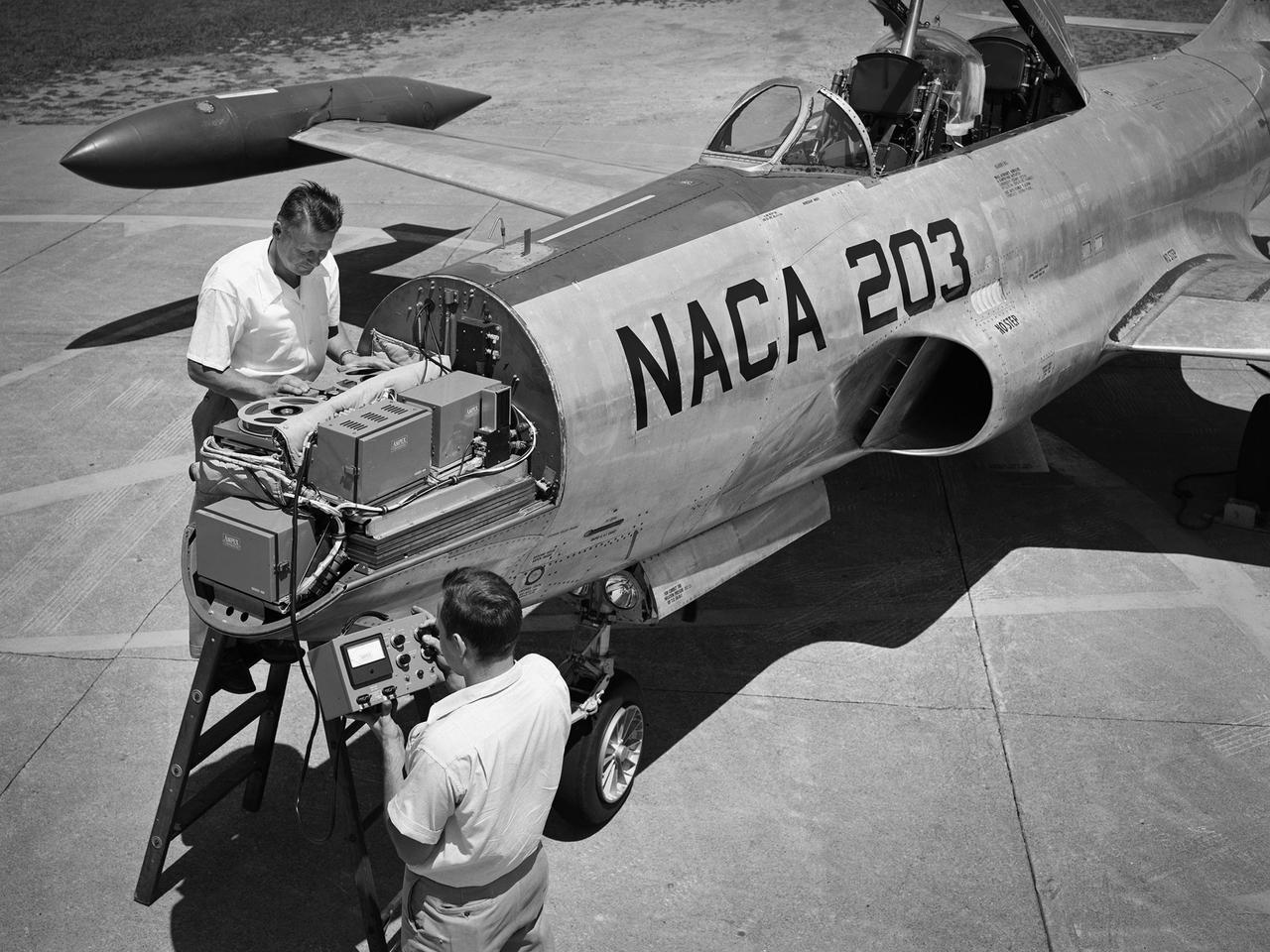
A Lockheed F-94B Starfire being equipped with an audio recording machine and sensors at the National Advisory Committee for Aeronautics (NACA) Lewis Flight Propulsion Laboratory. The NACA was investigating the acoustic effects caused by the engine’s nozzle and the air flowing along the fuselage. Airline manufacturers would soon be introducing jet engines on their passenger aircraft, and there was concern regarding the noise levels for both the passengers and public on the ground. NACA Lewis conducted a variety of noise reduction studies in its wind tunnels, laboratories, and on a F2H-2B Banshee aircraft. The F2H-2B Banshee’s initial test flights in 1955 and 1956 measured the noise emanating directly from airflow over the aircraft’s surfaces, particularly the wings. This problem was particularly pronounced at high subsonic speeds. The researchers found the majority of the noise occurred in the low and middle octaves. These investigations were enhanced with a series of flights using the F-94B Starfire. The missions measured wall-pressure, turbulence fluctuations, and mean velocity profiles. Mach 0.3 to 0.8 flights were flown at altitudes of 10,000, 20,000, and 30,000 feet with microphones mounted near the forward fuselage and on a wing. The results substantiated the wind tunnel findings. This photograph shows the tape recorder being installed in the F-94B’s nose.
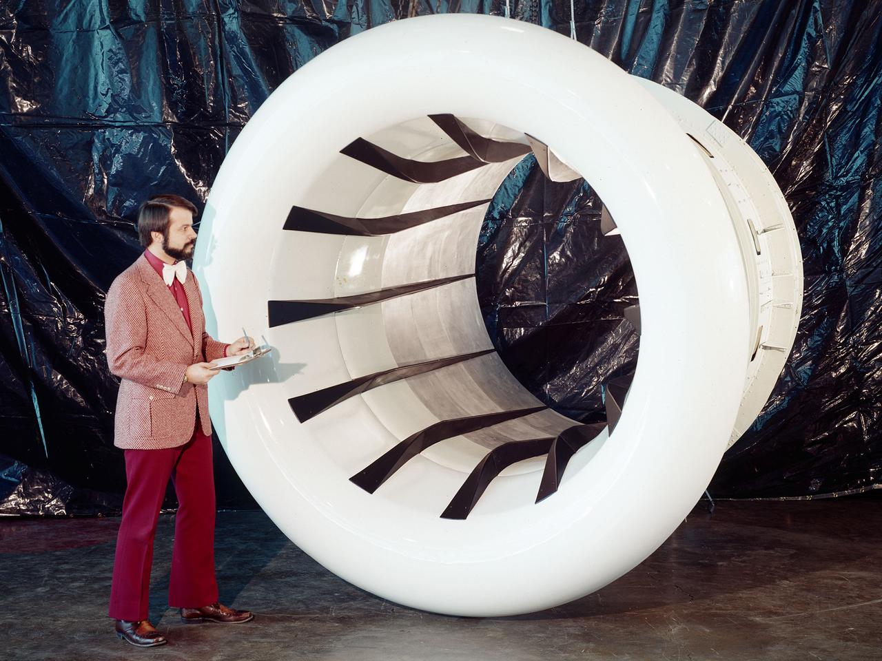
Brent Miller, of the V/STOL and Noise Division at the National Aeronautics and Space Administration (NASA) Lewis Research Center, poses with a sonic inlet for the NASA Quiet Engine Program. NASA Lewis had first investigated methods for reducing aircraft engine noise in the mid-1950s. Those efforts were resurrected and expanded in the late 1960s. The researchers found that the use of a sonic, or high-throat-Mach-number, inlet was effective at reducing the noise from the engine inlet. The device accelerated the inlet air to near-sonic speeds which kept the forward moving sound waves away from the inlet. The device also deflected the sound waves into the wall to further reduce the noise. NASA Lewis researchers tested models of the sonic inlet in their 9- by 15-Foot Low Speed Wind Tunnel. They found that the general level of aerodynamic performance was good. The tests during simulated takeoff and landing conditions demonstrated the sonic inlet’s ability to provide good aerodynamic and acoustic performance The researchers then successfully tested two full-scale sonic inlet designs, one from Pratt and Whitney and one from General Electric, with fans. A full-scale engine was installed on a thrust stand to determine the sonic inlet’s effect on the engine’s performance. The amount of noise reduction increased as the inlet flow velocity increased, but the full-scale tests did not produce as great a decrease in noise as the earlier small-scale tests.
National Aeronautics and Space Administration (NASA) Convair F-106B Delta Dart with a 32-spoke nozzle installed on its General Electric J85 test engine. Lewis acquired a Delta Dart fighter in 1966 to study the components for propulsion systems that could be applied to supersonic transport aircraft at transonic speeds. The F-106B was modified with two General Electric J85-13 engines under its wings to study these components. The original test plan was expanded to include the study of boattail drag, noise reduction, and inlets. From February to July 1971 the modified F-106B was used to study different ejector nozzles. Researchers conducted both acoustic and aerodynamic tests on the ground and in flight. Several models were created to test different suppression methods. NASA Lewis’ conical nozzle was used as the baseline configuration. Flightline and sideline microphones were set up on the ground. The F-106B would idle its own engine and buzz the recording station from an altitude of 300 feet at Mach 0.4 with the test engines firing. Researchers found that the suppression of the perceived noise level was usually lower during flight than the researchers had statistically predicted. The 64 and 32-spoke nozzles performed well in actual flight, but the others nozzles tended to negatively affect the engine’s performance. Different speeds or angles- -of-attack sometimes changed the noise levels. In the end, no general conclusions could be applied to all the nozzles.