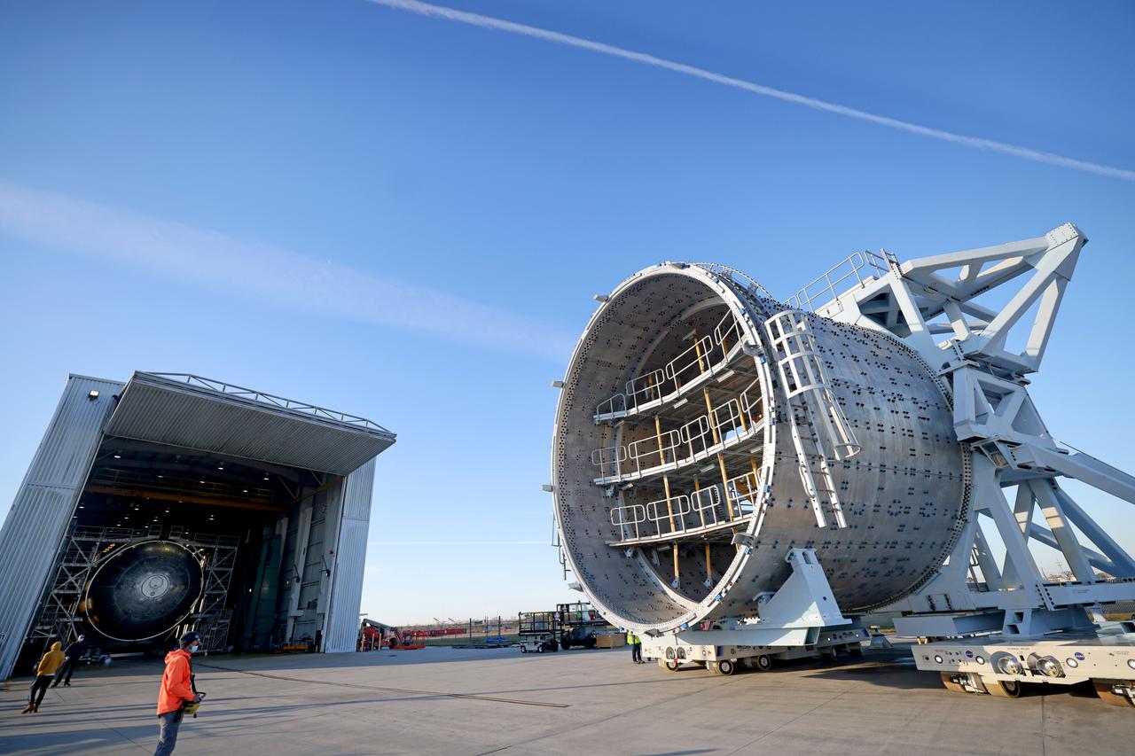
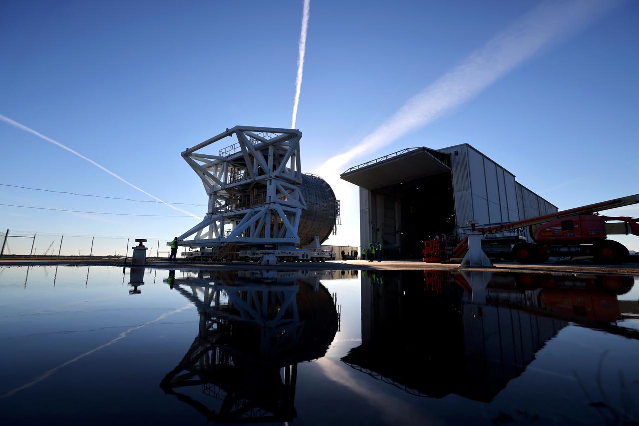
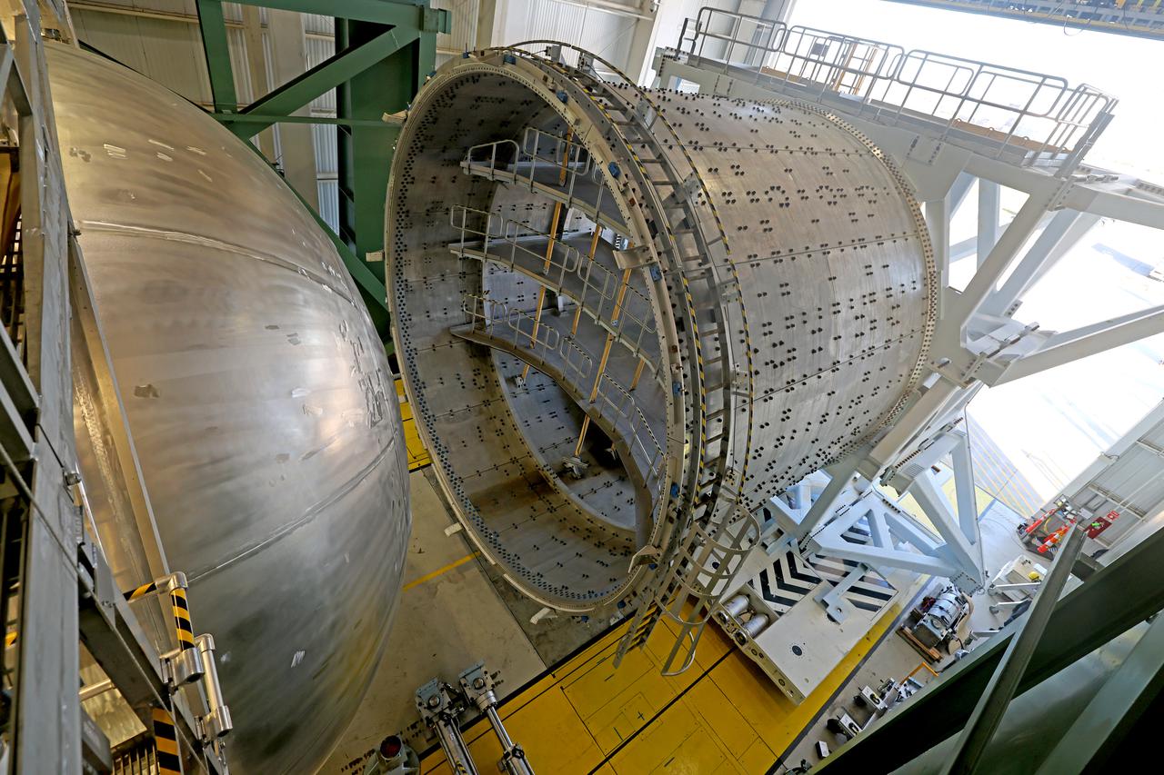
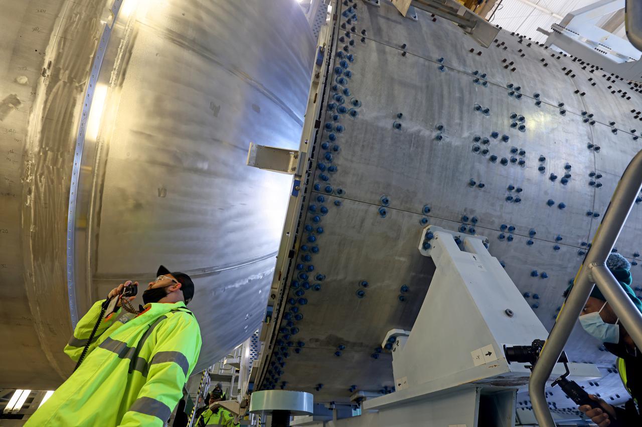
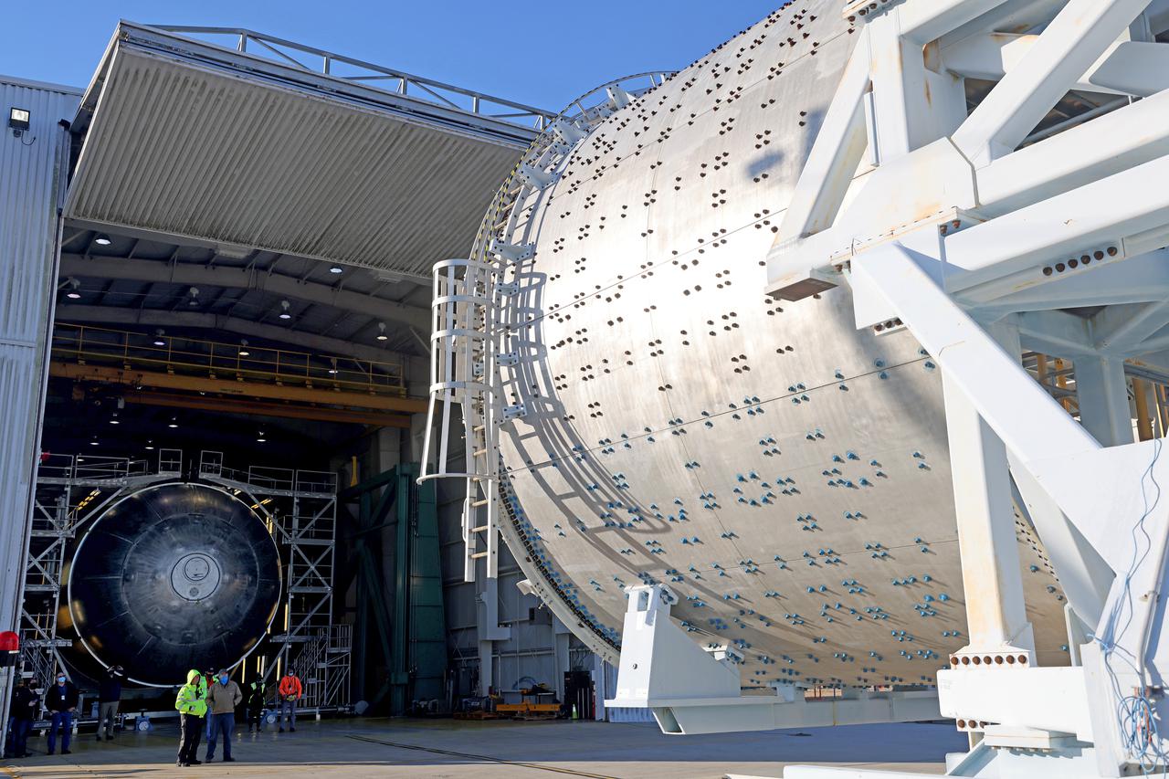
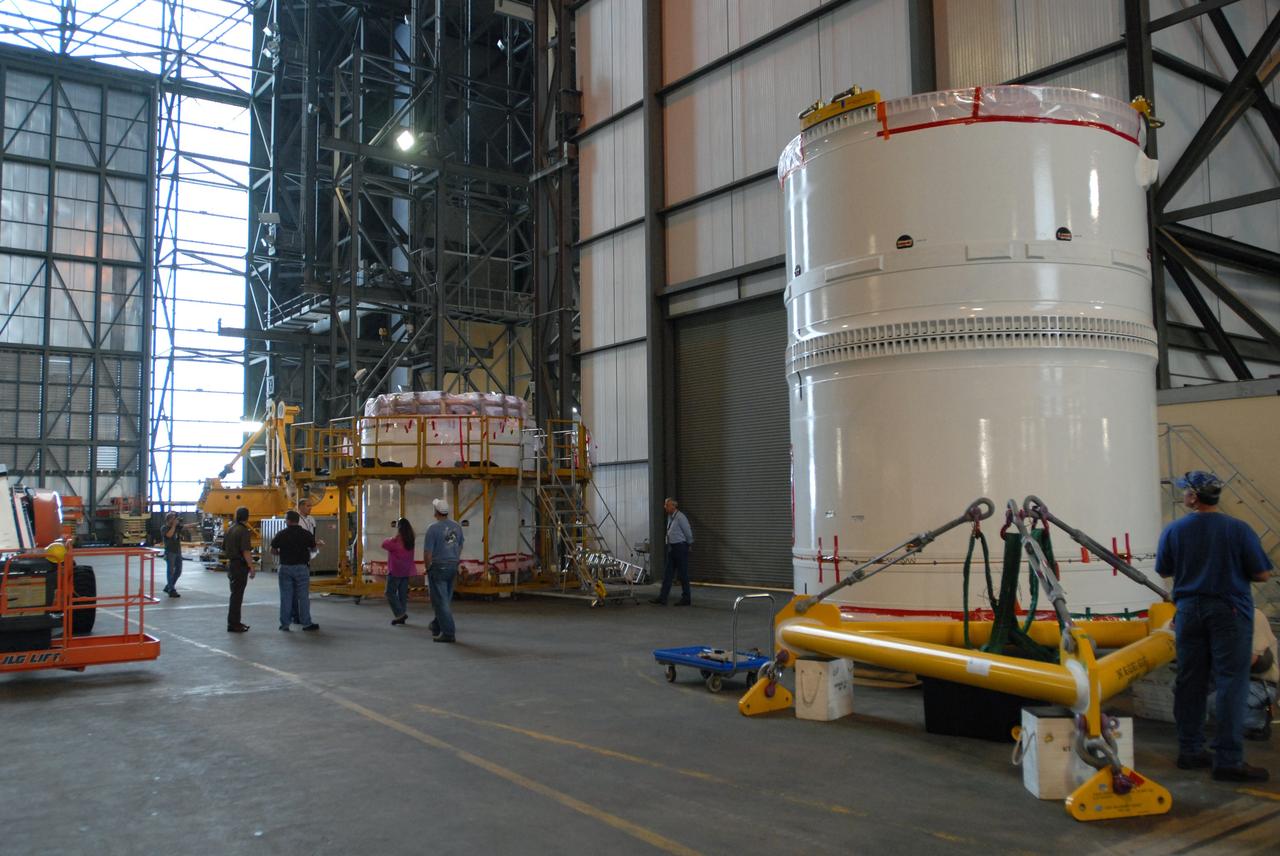
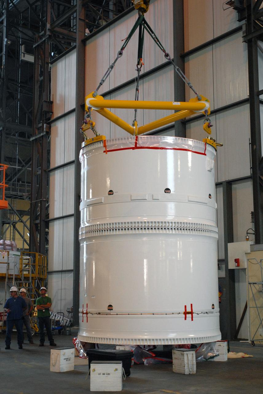
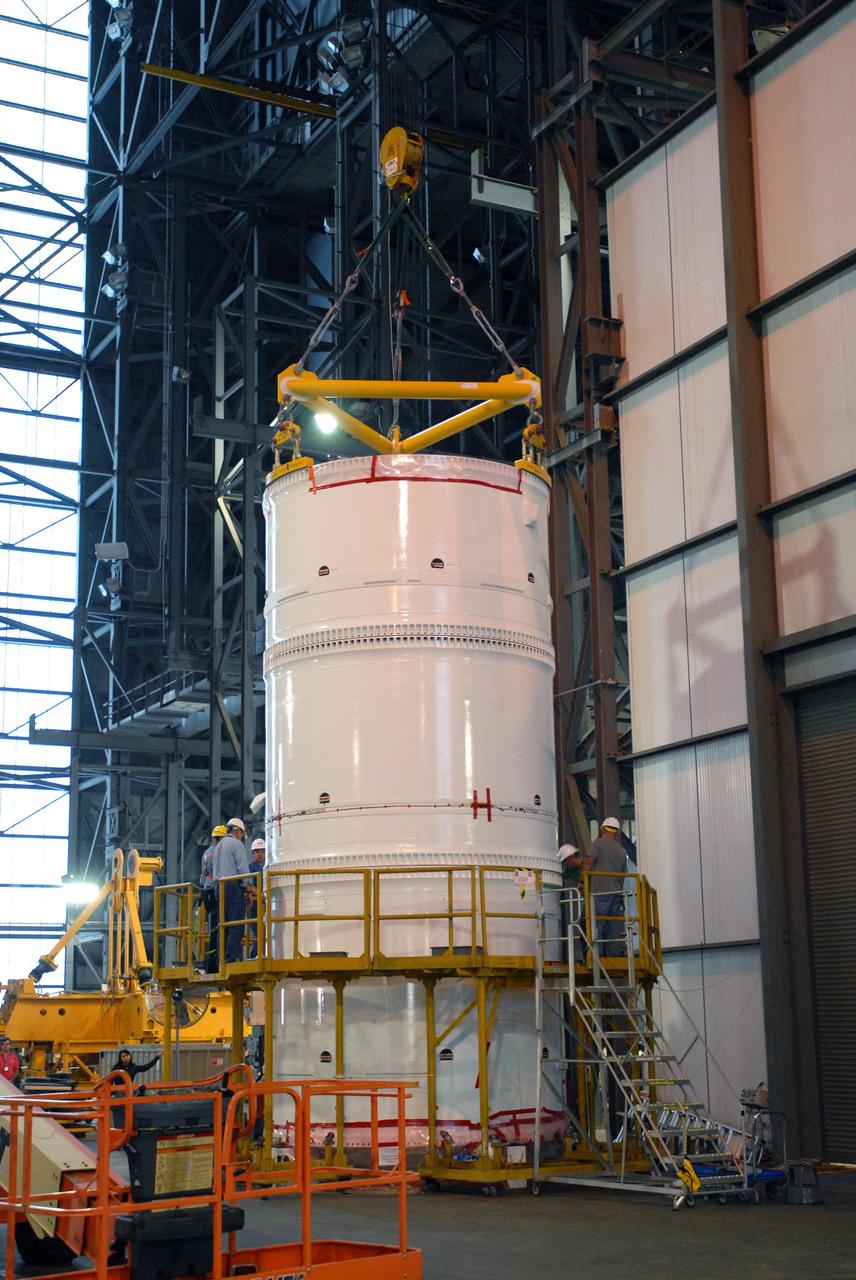
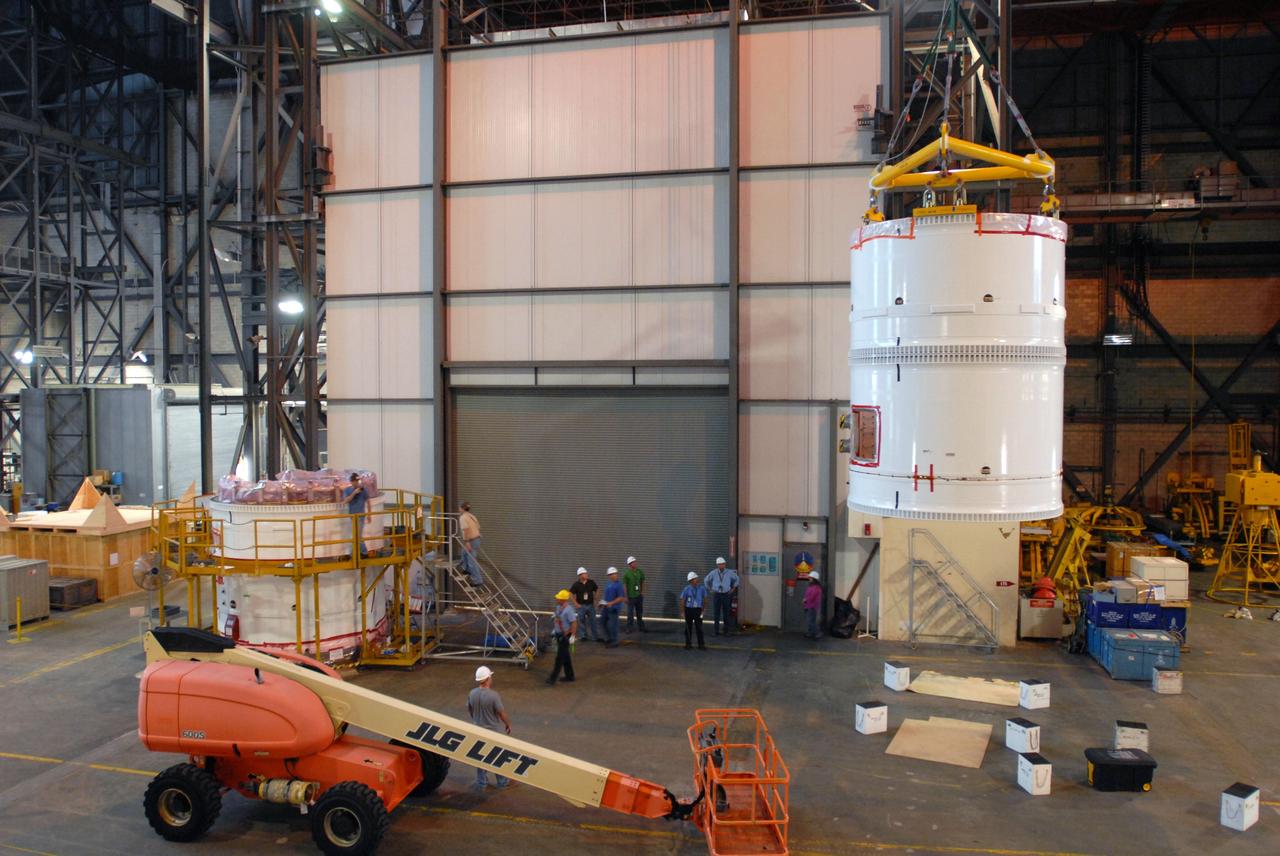
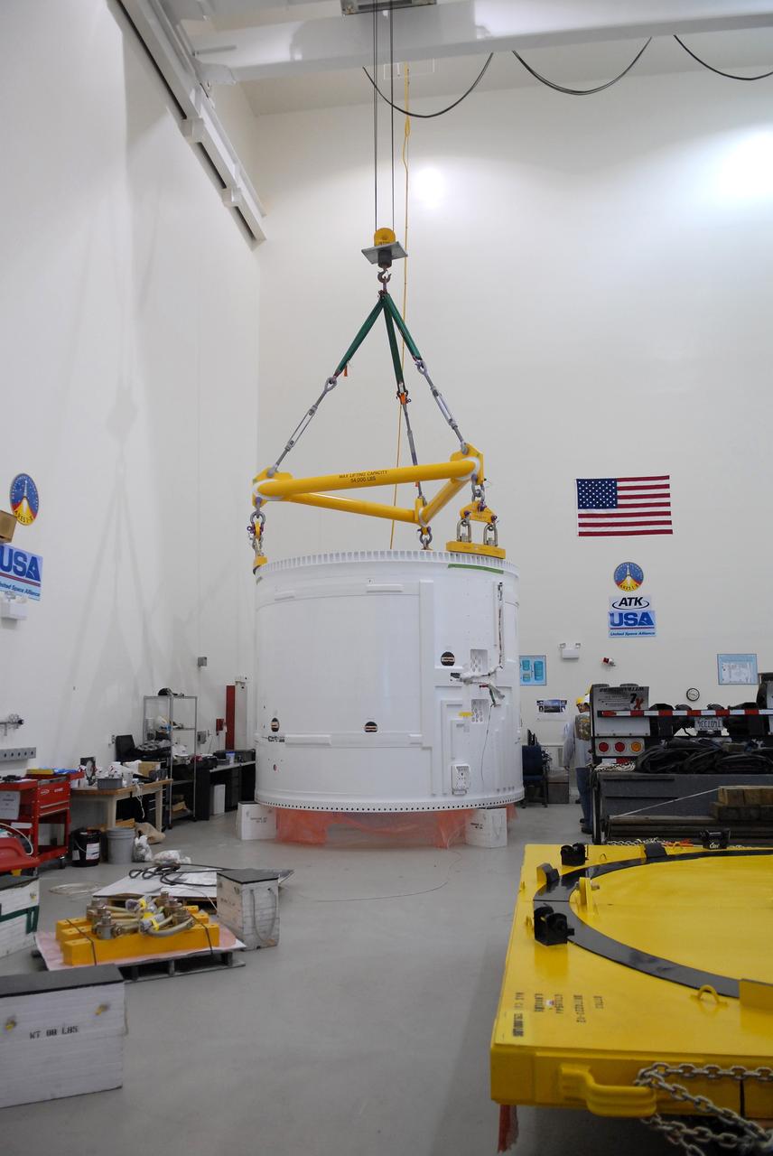
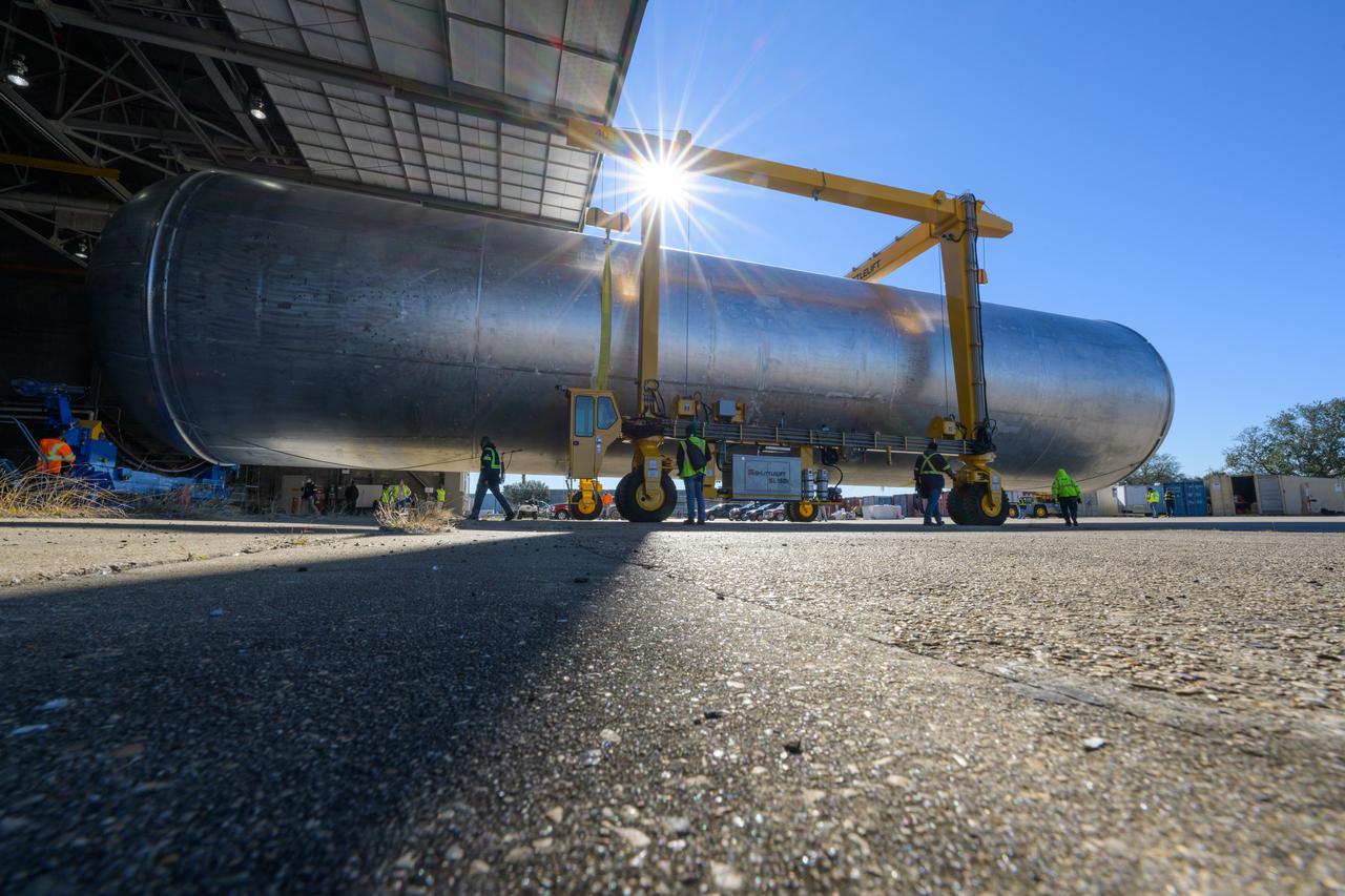
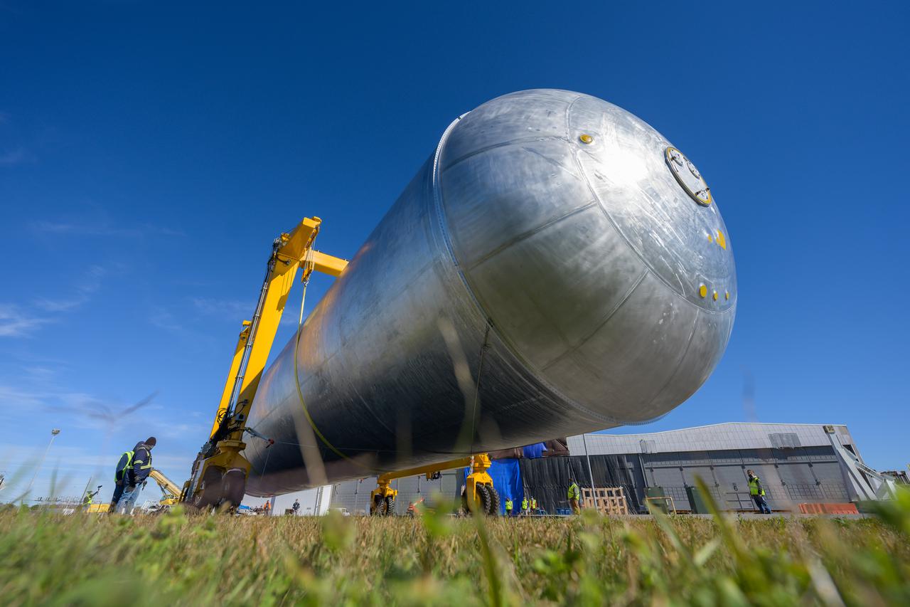
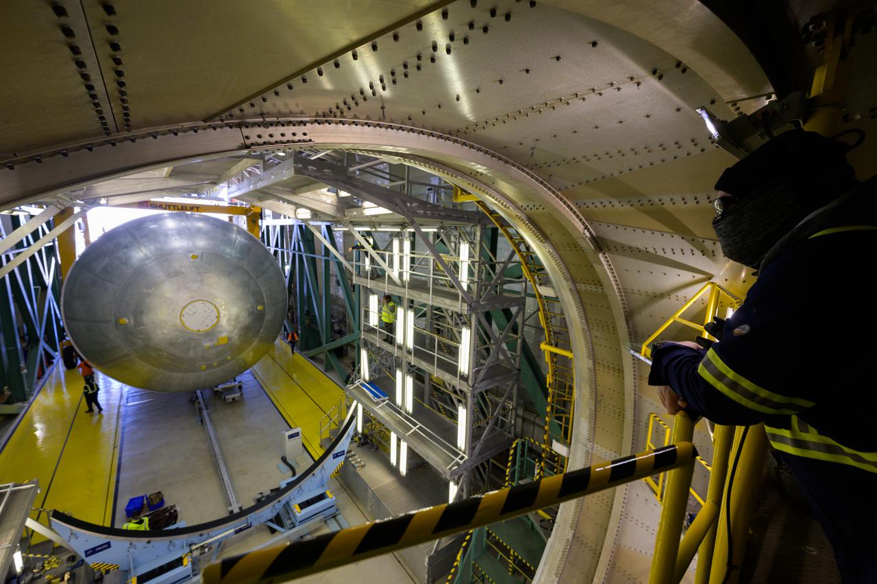
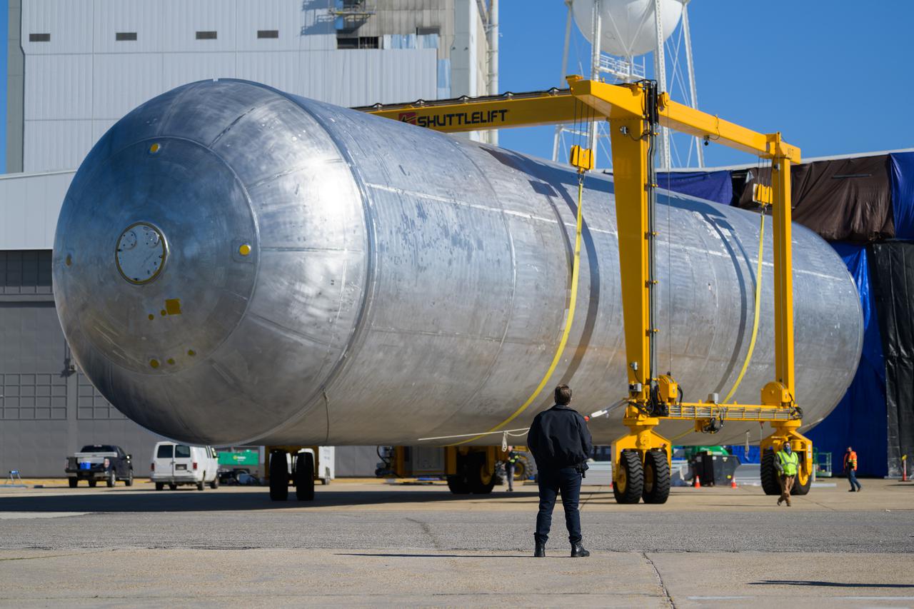
The liquid hydrogen tank that will be part of the Space Launch System rocket’s core stage is being prepared for the Artemis III mission at NASA’s Michoud Assembly Facility in New Orleans. Eventually, the tank will be connected to the engine section that will house the four RS-25 engines. The engine section is still being outfitted, so for this test crews attached an engine section aft simulator during proof testing on January 27, 2022. Once the aft simulator is attached, the LH2 tank undergoes non-destructive evaluation, which will test weld strength and ensure the tank is structurally sound. The SLS core stage is made up of five unique elements: the forward skirt, liquid oxygen tank, intertank, liquid hydrogen tank, and the engine section. The tank holds 537,000 gallons of liquid hydrogen cooled to minus 432 degrees Fahrenheit and sits between the core stage’s intertank and engine section. The liquid hydrogen hardware, along with the liquid oxygen tank, will provide propellant to the four RS-25 engines at the bottom of the core stage to produce more than two million pounds of thrust to help launch the Artemis III mission to the Moon. Together with its four RS-25 engines, the rocket’s massive 212-foot-tall core stage — the largest stage NASA has ever built — and its twin solid rocket boosters will produce 8.8 million pounds of thrust to send NASA’s Orion spacecraft, astronauts and supplies beyond Earth’s orbit to the Moon. Image credit: NASA/Michael DeMocker
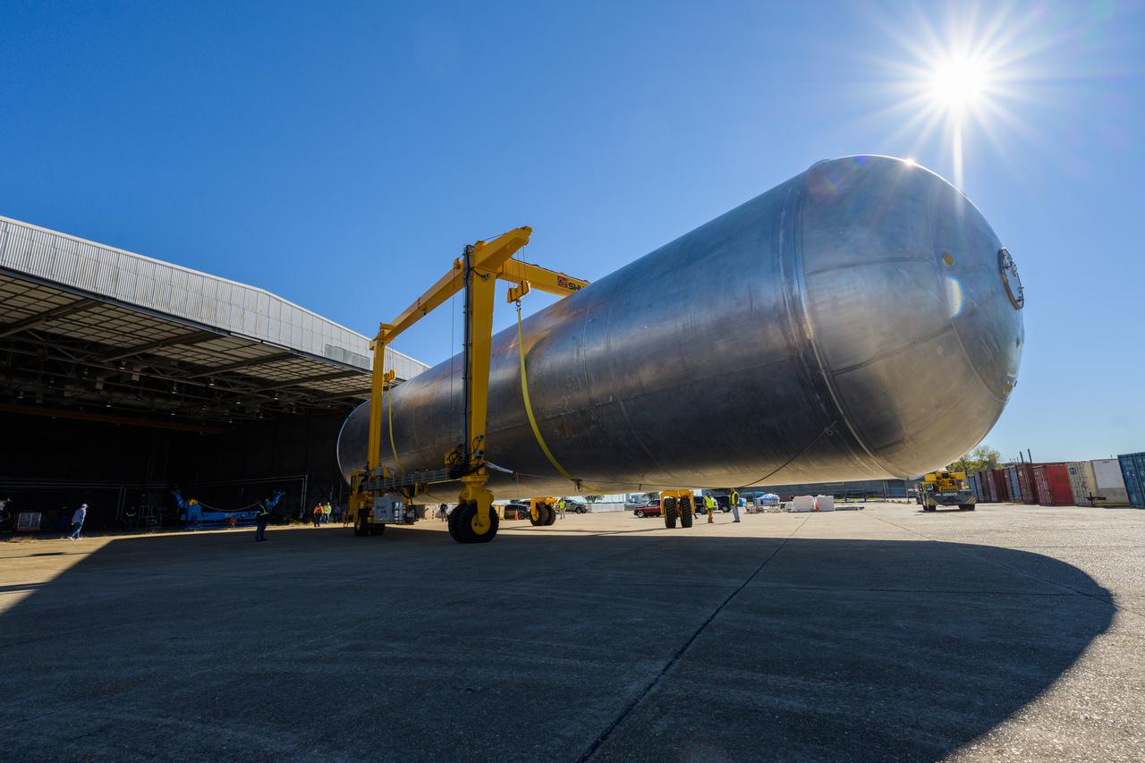
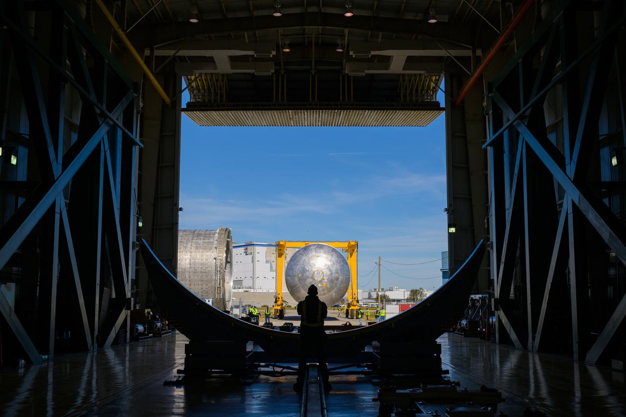
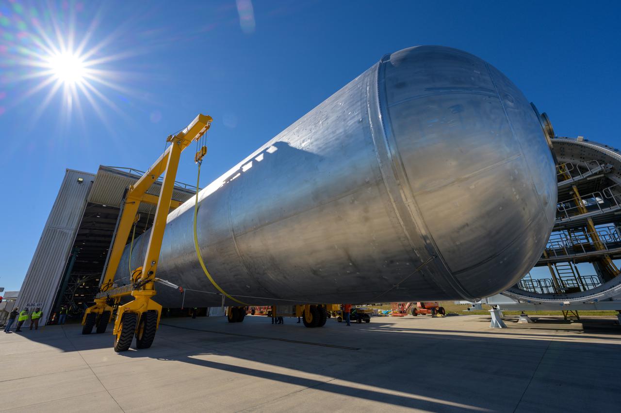
The liquid hydrogen tank that will be part of the Space Launch System rocket’s core stage is being prepared for the Artemis III mission at NASA’s Michoud Assembly Facility in New Orleans. Eventually, the tank will be connected to the engine section that will house the four RS-25 engines. The engine section is still being outfitted, so for this test crews attached an engine section aft simulator during proof testing on January 27, 2022. Once the aft simulator is attached, the LH2 tank undergoes non-destructive evaluation, which will test weld strength and ensure the tank is structurally sound. The SLS core stage is made up of five unique elements: the forward skirt, liquid oxygen tank, intertank, liquid hydrogen tank, and the engine section. The tank holds 537,000 gallons of liquid hydrogen cooled to minus 432 degrees Fahrenheit and sits between the core stage’s intertank and engine section. The liquid hydrogen hardware, along with the liquid oxygen tank, will provide propellant to the four RS-25 engines at the bottom of the core stage to produce more than two million pounds of thrust to help launch the Artemis III mission to the Moon. Together with its four RS-25 engines, the rocket’s massive 212-foot-tall core stage — the largest stage NASA has ever built — and its twin solid rocket boosters will produce 8.8 million pounds of thrust to send NASA’s Orion spacecraft, astronauts and supplies beyond Earth’s orbit to the Moon. Image credit: NASA/Michael DeMocker
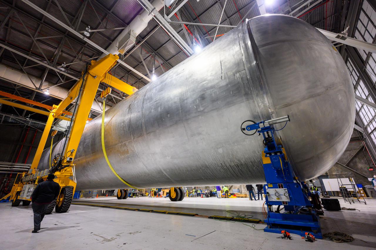
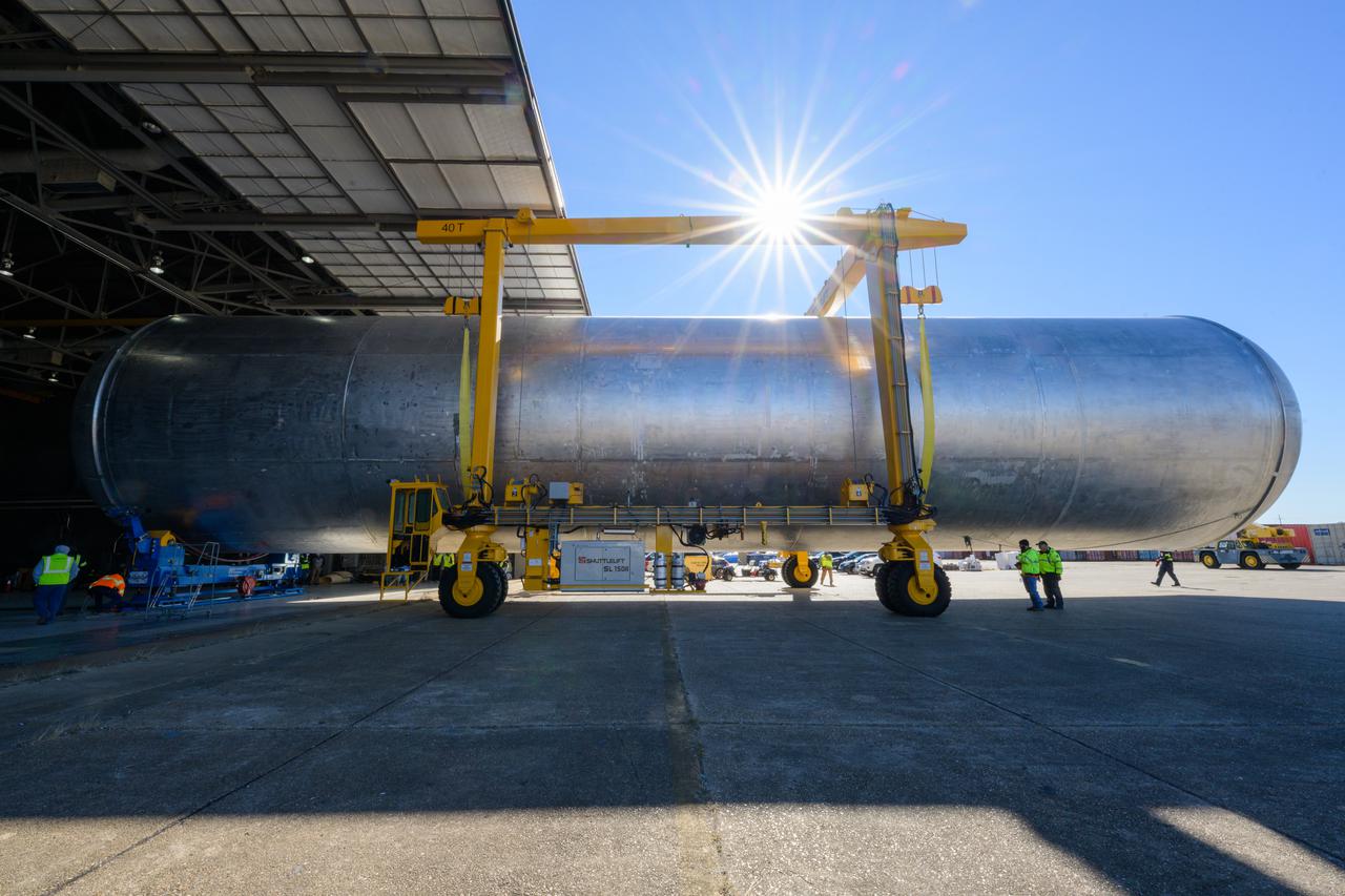
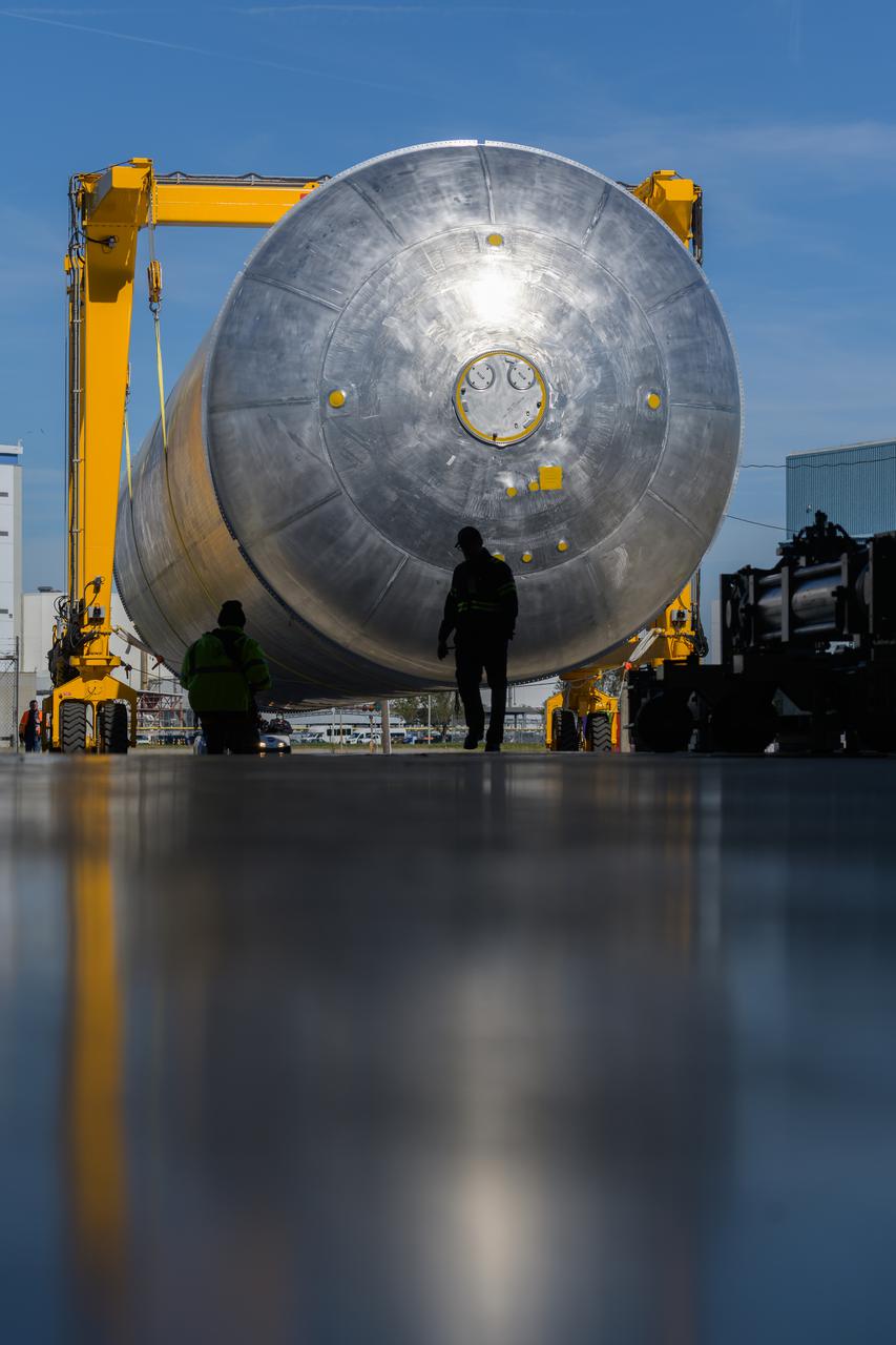
The liquid hydrogen tank that will be part of the Space Launch System rocket’s core stage is being prepared for the Artemis III mission at NASA’s Michoud Assembly Facility in New Orleans. Eventually, the tank will be connected to the engine section that will house the RS-25 engines. The engine section is still being outfitted, so for this test crews attached an engine section aft simulator during proof testing on January 27, 2022. Once the aft simulator is attached, the LH2 tank undergoes non-destructive evaluation, which will test weld strength and ensure the tank is structurally sound. The SLS core stage is made up of five unique elements: the forward skirt, liquid oxygen tank, intertank, liquid hydrogen tank, and the engine section. The tank holds 537,000 gallons of liquid hydrogen cooled to minus 432 degrees Fahrenheit and sits between the core stage’s intertank and engine section. The liquid hydrogen hardware, along with the liquid oxygen tank, will provide propellant to the four RS-25 engines at the bottom of the core stage to produce more than two million pounds of thrust to help launch the Artemis III mission to the Moon. Together with its four RS-25 engines, the rocket’s massive 212-foot-tall core stage — the largest stage NASA has ever built — and its twin solid rocket boosters will produce 8.8 million pounds of thrust to send NASA’s Orion spacecraft, astronauts and supplies beyond Earth’s orbit to the Moon. Image credit: NASA/Michael DeMocker
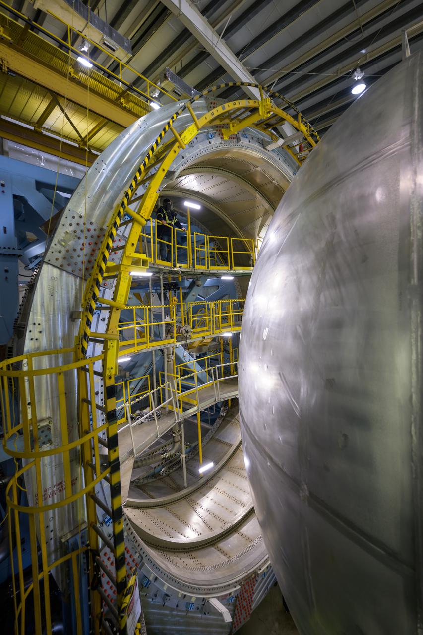
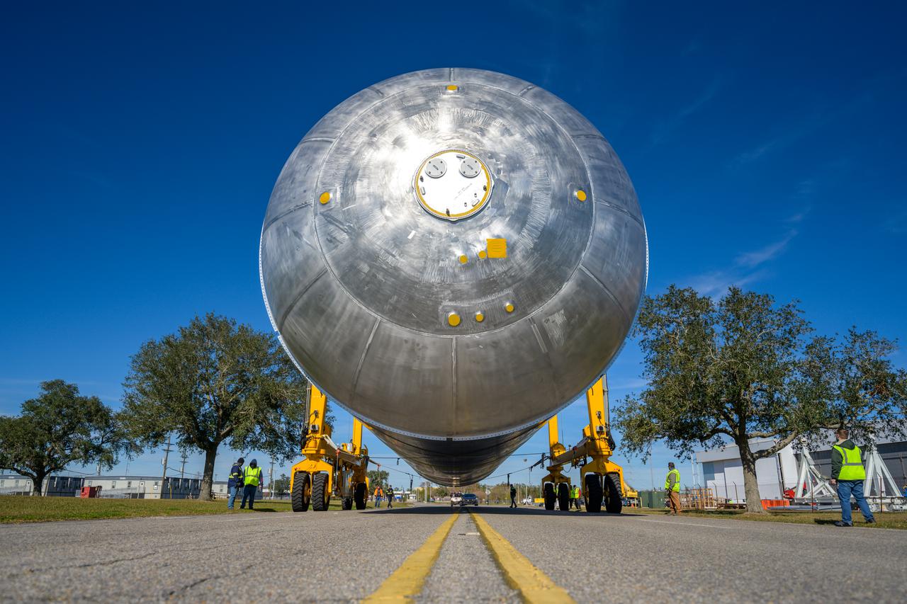
The liquid hydrogen tank that will be part of the Space Launch System rocket’s core stage is being prepared for the Artemis III mission at NASA’s Michoud Assembly Facility in New Orleans. Eventually, the tank will be connected to the engine section that will house the four RS-25 engines. The engine section is still being outfitted, so for this test crews attached an engine section aft simulator during proof testing on January 27, 2022. Once the aft simulator is attached, the LH2 tank undergoes non-destructive evaluation, which will test weld strength and ensure the tank is structurally sound. The SLS core stage is made up of five unique elements: the forward skirt, liquid oxygen tank, intertank, liquid hydrogen tank, and the engine section. The tank holds 537,000 gallons of liquid hydrogen cooled to minus 432 degrees Fahrenheit and sits between the core stage’s intertank and engine section. The liquid hydrogen hardware, along with the liquid oxygen tank, will provide propellant to the four RS-25 engines at the bottom of the core stage to produce more than two million pounds of thrust to help launch the Artemis III mission to the Moon. Together with its four RS-25 engines, the rocket’s massive 212-foot-tall core stage — the largest stage NASA has ever built — and its twin solid rocket boosters will produce 8.8 million pounds of thrust to send NASA’s Orion spacecraft, astronauts and supplies beyond Earth’s orbit to the Moon. Image credit: NASA/Michael DeMocker
The liquid hydrogen tank that will be part of the Space Launch System rocket’s core stage is being prepared for the Artemis III mission at NASA’s Michoud Assembly Facility in New Orleans. Eventually, the tank will be connected to the engine section that will house the four RS-25 engines. The engine section is still being outfitted, so for this test crews attached an engine section aft simulator during proof testing on January 27, 2022. Once the aft simulator is attached, the LH2 tank undergoes non-destructive evaluation, which will test weld strength and ensure the tank is structurally sound. The SLS core stage is made up of five unique elements: the forward skirt, liquid oxygen tank, intertank, liquid hydrogen tank, and the engine section. The tank holds 537,000 gallons of liquid hydrogen cooled to minus 432 degrees Fahrenheit and sits between the core stage’s intertank and engine section. The liquid hydrogen hardware, along with the liquid oxygen tank, will provide propellant to the four RS-25 engines at the bottom of the core stage to produce more than two million pounds of thrust to help launch the Artemis III mission to the Moon. Together with its four RS-25 engines, the rocket’s massive 212-foot-tall core stage — the largest stage NASA has ever built — and its twin solid rocket boosters will produce 8.8 million pounds of thrust to send NASA’s Orion spacecraft, astronauts and supplies beyond Earth’s orbit to the Moon. Image credit: NASA/Michael DeMocker
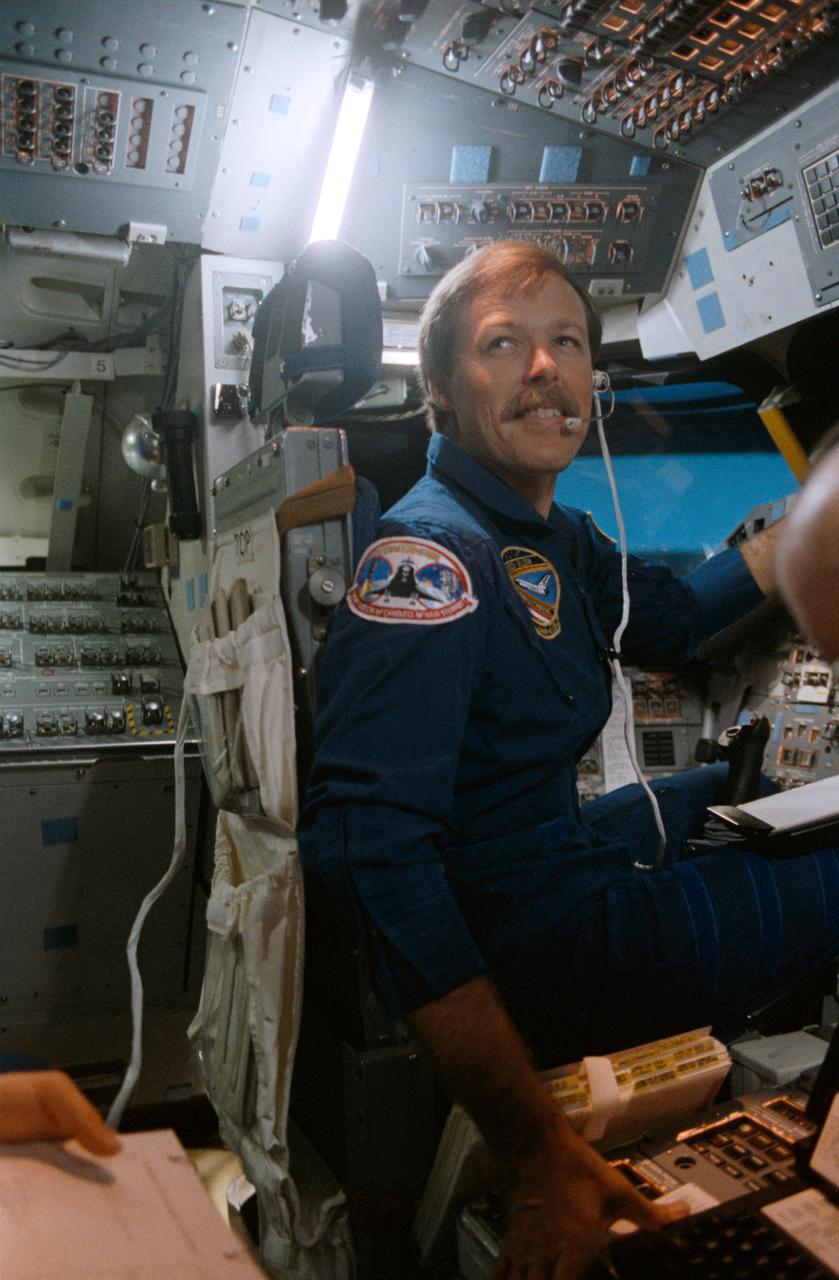
STS-27 Atlantis, Orbiter Vehicle (OV) 104, Commander Robert L. Gibson, wearing flight coveralls and communications kit assembly, sits at commanders station controls on JSC shuttle mission simulator (SMS) forward flight deck during training session. Gibson looks at crewmember on aft flight deck. SMS is located in the Mission Simulation and Training Facility Bldg 5.
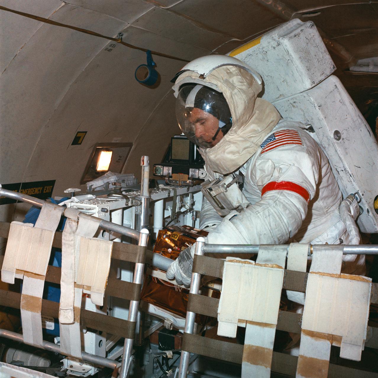
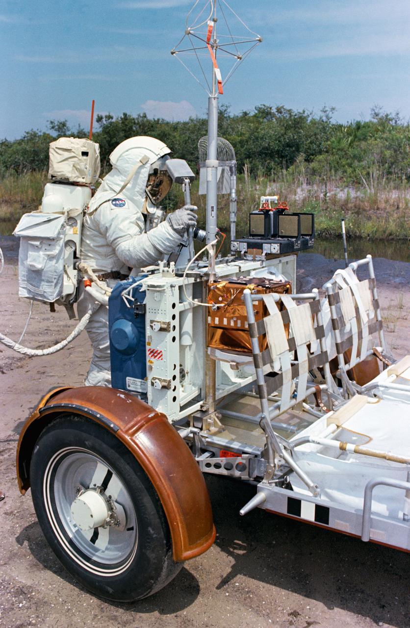
S72-50270 (September 1972) --- Astronaut Eugene A. Cernan, commander of the Apollo 17 lunar landing mission, participates in lunar surface extravehicular activity simulation training under one-sixth gravity conditions aboard a U. S. Air Force KC-135 aircraft. Here, Cernan simulates removing an experiment package from the aft end of a Lunar Roving Vehicle.
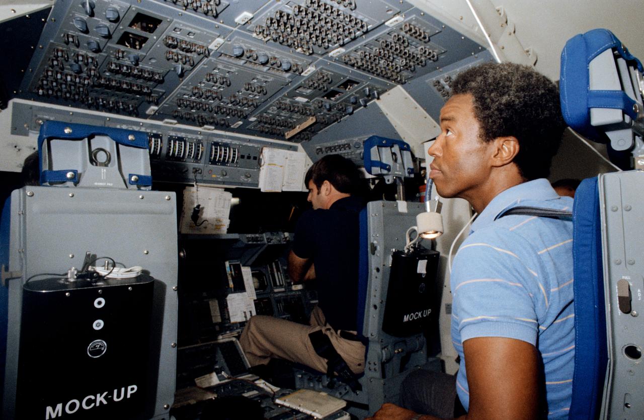
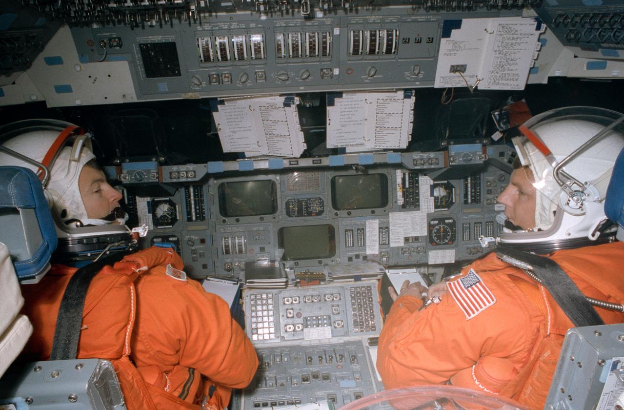
S83-33032 (23 May 1983) --- Astronauts Guion S. Bluford, right, and Daniel C. Brandenstein man their respective Challenger entry and ascent stations in the Shuttle Mission Simulator (SMS) at NASA's Johnson Space Center (JSC) during a training session for the STS-8 mission. Brandenstein is in the pilot's station, while Bluford, a mission specialist, occupies one of the two aft flight deck seats. Both are wearing civilian clothes for this training exercise. This motion based simulator represents the scene of a great deal of training and simulation activity, leading up to crew preparedness for Space Transportation System (STS) mission. Photo credt: NASA/Otis Imboden, National Geographic
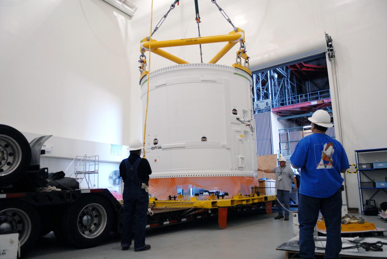
CAPE CANAVERAL, Fla. – In the Vehicle Assembly Building's extended duration orbiter lab, or EDO, at NASA's Kennedy Space Center in Florida, the Ares I-X fifth segment simulator aft section is lifted by a crane from the transporter. The aft section will be moved to a stand. Ares I-X is the test vehicle for the Ares I, which is part of the Constellation Program to return men to the moon and beyond. Ares I is the essential core of a safe, reliable, cost-effective space transportation system that eventually will carry crewed missions back to the moon, on to Mars and out into the solar system. Ares I-X is targeted for launch in July 2009. Photo credit: NASA/Troy Cryder
CAPE CANAVERAL, Fla. – In the transfer aisle of the Vehicle Assembly Building at NASA's Kennedy Space Center in Florida, workers monitor the conjoined forward and center segments of the fifth segment simulator for the Ares I-X as a crane lifts them toward the simulator’s aft segment. Ares I-X is the test vehicle for the Ares I, a component of the Constellation Program to return men to the moon and beyond. Ares I is the essential core of a safe, reliable, cost-effective space transportation system that eventually will carry crewed missions back to the moon, on to Mars and out into the solar system. The launch of the Ares I-X flight test is targeted for August 2009. Photo credit: NASA/Jim Grossmann
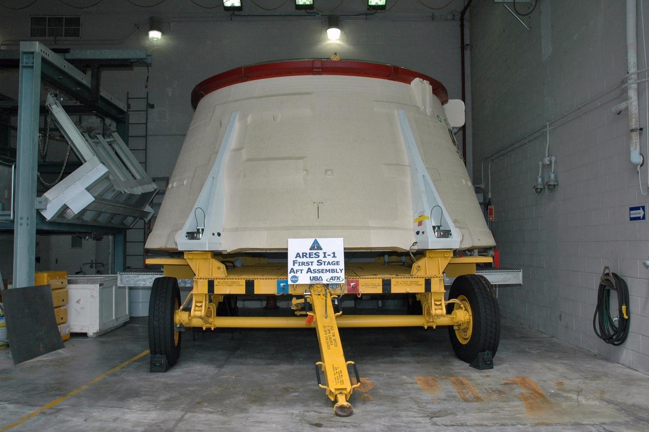
KENNEDY SPACE CENTER, FLA. - In the Assembly and Refurbishment Facility at NASA's Kennedy Space Center, the solid rocket booster aft skirt designated for use on the first stage of the ARES I-1 launch vehicle is being prepared for its first test flight. Ares I is the vehicle being developed for launch of the crew exploration vehicle (CEV), named Orion. Ares I-1 is currently targeted for launch from Launch Pad 39B in 2009 using the SRB first stage and a simulated second stage and simulated CEV. Ares I ascent tests and Ares I orbital tests will also take place at Kennedy at later dates. Photo credit: NASA/Jack Pfaller
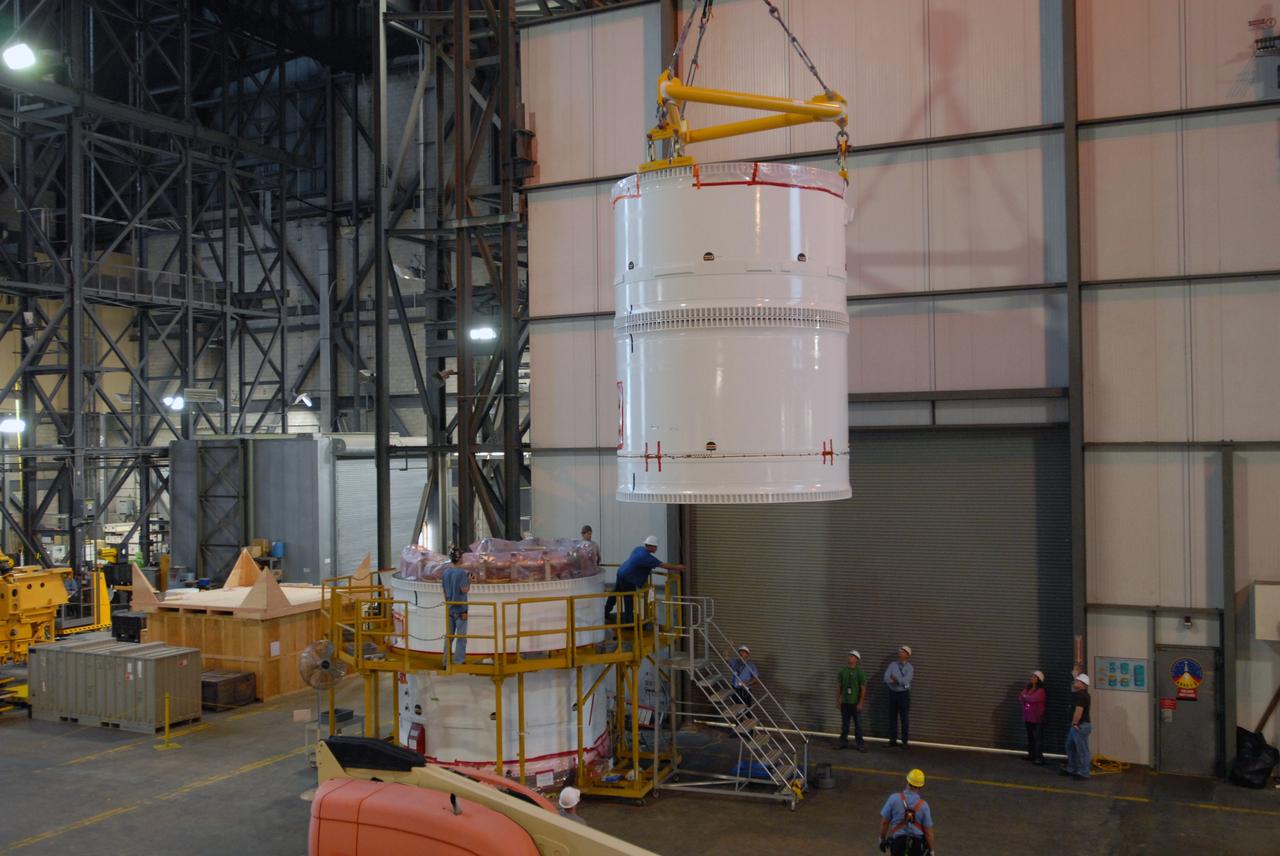
CAPE CANAVERAL, Fla. – In the transfer aisle of the Vehicle Assembly Building at NASA's Kennedy Space Center in Florida, a crane lowers the conjoined forward and center segments of the fifth segment simulator for the Ares I-X onto the simulator’s aft segment. Ares I-X is the test vehicle for the Ares I, a component of the Constellation Program to return men to the moon and beyond. Ares I is the essential core of a safe, reliable, cost-effective space transportation system that eventually will carry crewed missions back to the moon, on to Mars and out into the solar system. The launch of the Ares I-X flight test is targeted for August 2009. Photo credit: NASA/Jim Grossmann
CAPE CANAVERAL, Fla. – In the transfer aisle of the Vehicle Assembly Building at NASA's Kennedy Space Center in Florida, workers prepare to lift the conjoined forward and center segments of the fifth segment simulator for the Ares I-X. The segments will be mated to the simulator’s aft segment, at left. Ares I-X is the test vehicle for the Ares I, a component of the Constellation Program to return men to the moon and beyond. Ares I is the essential core of a safe, reliable, cost-effective space transportation system that eventually will carry crewed missions back to the moon, on to Mars and out into the solar system. The launch of the Ares I-X flight test is targeted for August 2009. Photo credit: NASA/Jim Grossmann
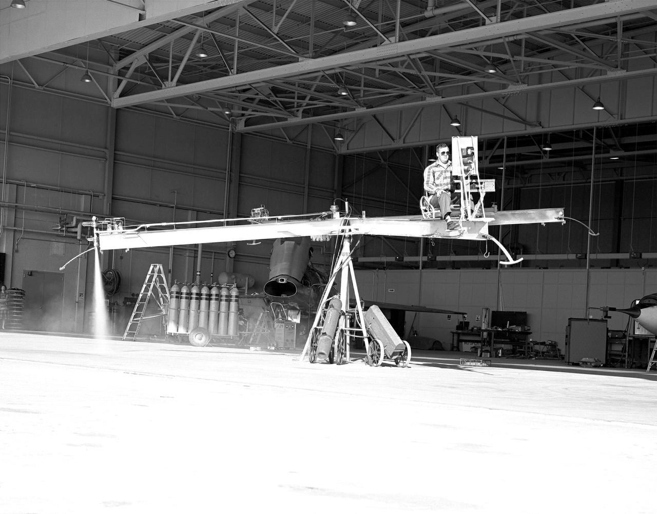
NACA High-Speed Flight Station test pilot Stan Butchart flying the Iron Cross, the mechanical reaction control simulator. High-pressure nitrogen gas expanded selectively, by the pilot, through the small reaction control thrusters maneuvered the Iron Cross through the three axes. The exhaust plume can be seen from the aft thruster. The tanks containing the gas can be seen on the cart at the base of the pivot point of the Iron Cross. NACA technicians built the iron-frame simulator, which matched the inertia ratios of the Bell X-1B airplane, installing six jet nozzles to control the movement about the three axes of pitch, roll, and yaw.
CAPE CANAVERAL, Fla. – In the transfer aisle of the Vehicle Assembly Building at NASA's Kennedy Space Center in Florida, the conjoined forward and center segments of the fifth segment simulator for the Ares I-X is attached to a crane prior to lifting operations. The segments will be mated to the simulator’s aft segment. Ares I-X is the test vehicle for the Ares I, a component of the Constellation Program to return men to the moon and beyond. Ares I is the essential core of a safe, reliable, cost-effective space transportation system that eventually will carry crewed missions back to the moon, on to Mars and out into the solar system. The launch of the Ares I-X flight test is targeted for August 2009. Photo credit: NASA/Jim Grossmann
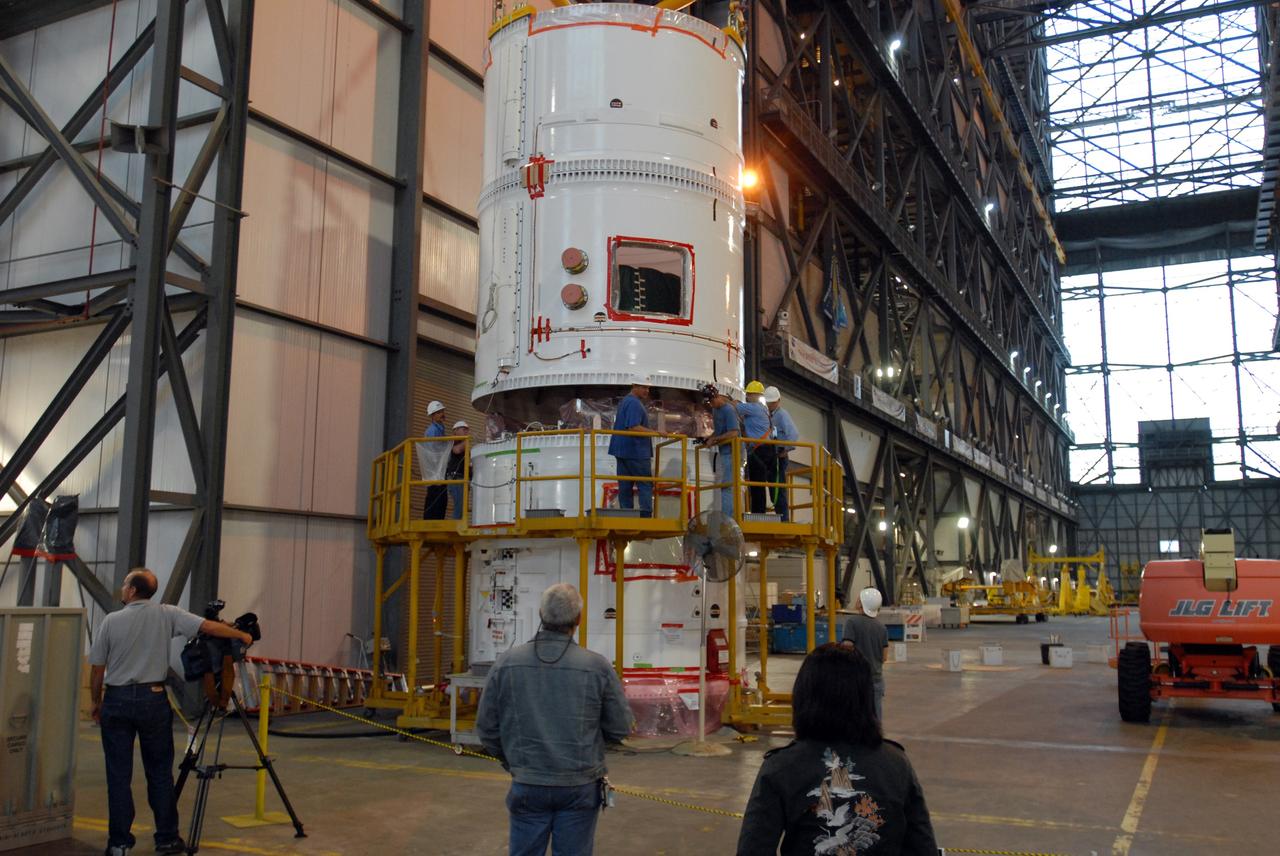
CAPE CANAVERAL, Fla. – In the transfer aisle of the Vehicle Assembly Building at NASA's Kennedy Space Center in Florida, the conjoined forward and center segments of the fifth segment simulator for the Ares I-X is secured to the simulator’s aft segment. Ares I-X is the test vehicle for the Ares I, a component of the Constellation Program to return men to the moon and beyond. Ares I is the essential core of a safe, reliable, cost-effective space transportation system that eventually will carry crewed missions back to the moon, on to Mars and out into the solar system. The launch of the Ares I-X flight test is targeted for August 2009. Photo credit: NASA/Jim Grossmann
CAPE CANAVERAL, Fla. – In the transfer aisle of the Vehicle Assembly Building at NASA's Kennedy Space Center in Florida, a crane lifts the conjoined forward and center segments of the fifth segment simulator for the Ares I-X. The segments will be mated to the simulator’s aft segment, at left. Ares I-X is the test vehicle for the Ares I, a component of the Constellation Program to return men to the moon and beyond. Ares I is the essential core of a safe, reliable, cost-effective space transportation system that eventually will carry crewed missions back to the moon, on to Mars and out into the solar system. The launch of the Ares I-X flight test is targeted for August 2009. Photo credit: NASA/Jim Grossmann
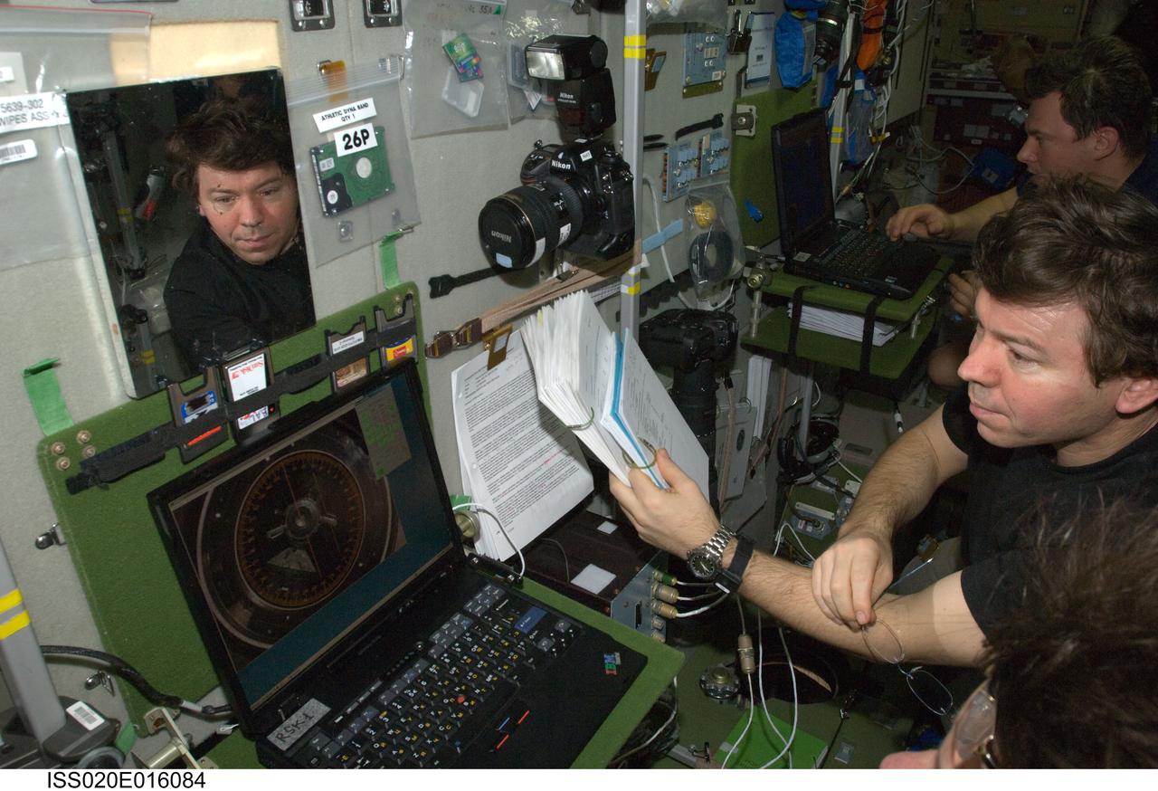
ISS020-E-016084 (1 July 2009) --- NASA astronaut Michael Barratt, Expedition 20 flight engineer, uses an onboard laptop-based simulator in the Zvezda Service Module of the International Space Station to prepare for the relocation of the Soyuz TMA-14 spacecraft from Zvezda?s aft port to the Pirs Docking Compartment on July 2, 2009. Cosmonaut Roman Romanenko, flight engineer, is visible in the background.
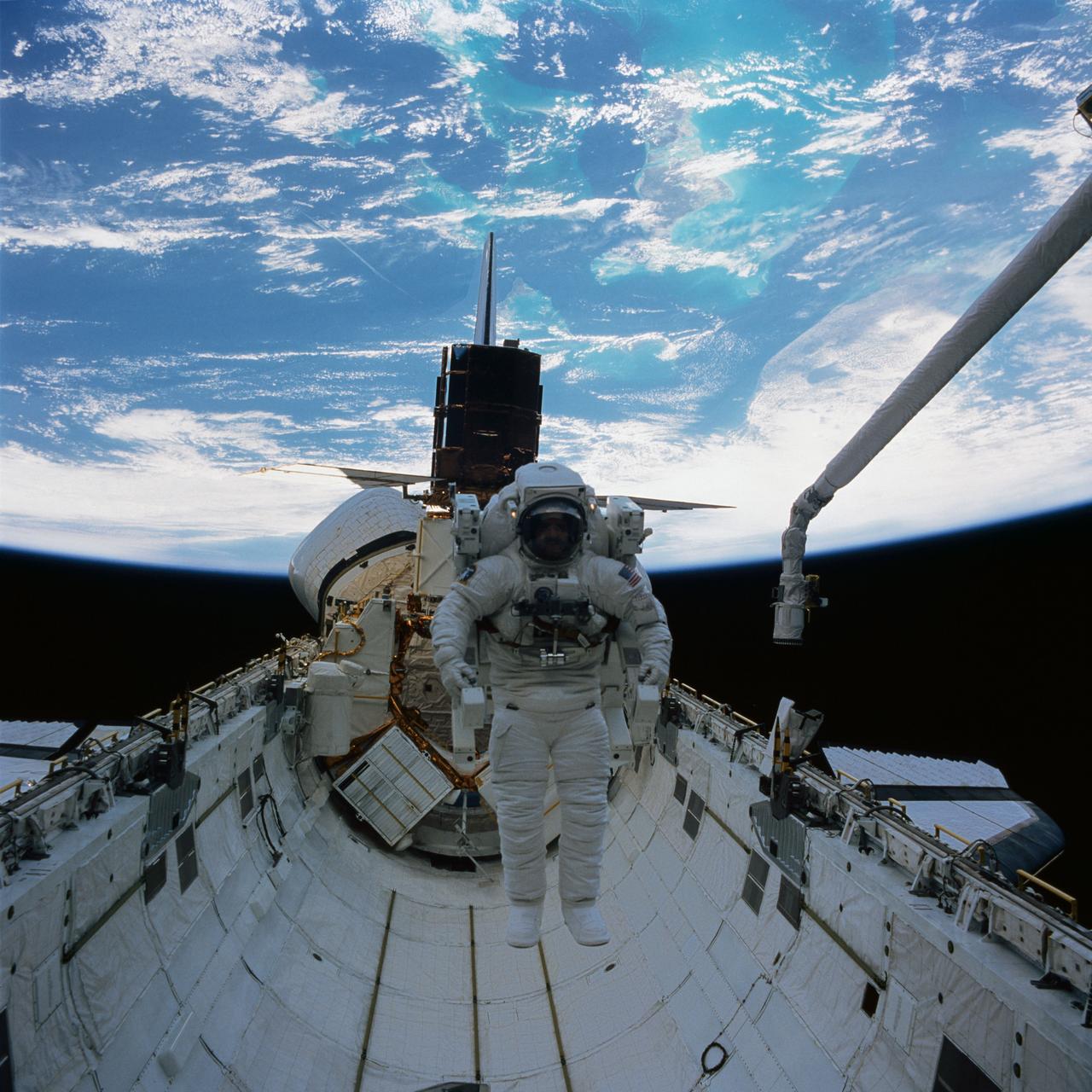
41C-37-1718 (11 April 1984) --- Astronaut James D. van Hoften and a repaired satellite are captured by a Hasselblad camera aimed through Challenger's aft cabin windows toward the cargo bay of the Earth orbiting Challenger. Dr. van Hoften is getting in his first "field" test of the manned maneuvering unit (MMU) after months of training in an underwater facility and in a simulator on Earth. The Solar Maximum Mission Satellite (SMMS), revived and almost ready for release into space once more, is docked at the flight support system (FSS).
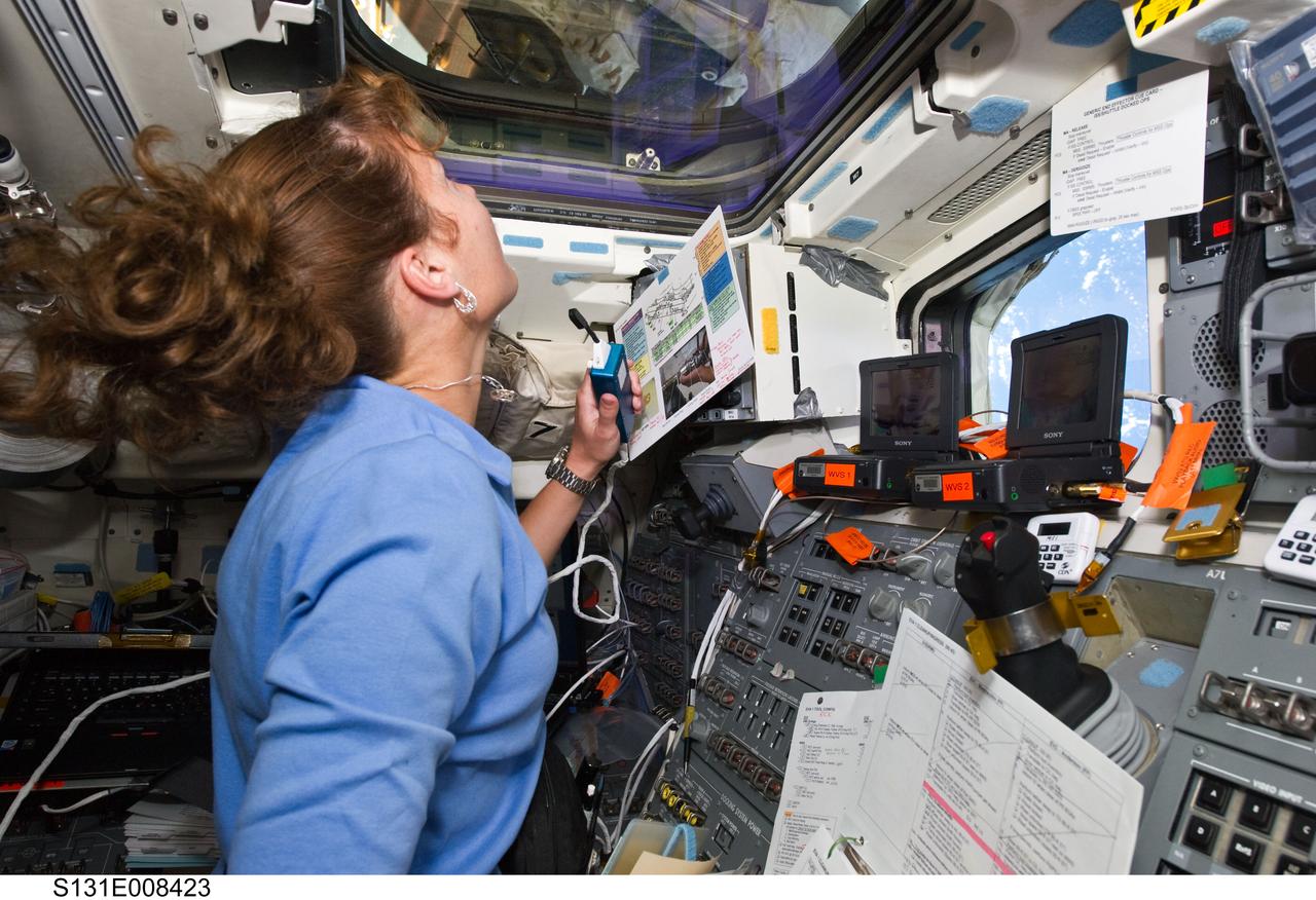
S131-E-008423 (9 April 2010) --- After many months of training in simulators, NASA astronaut Dorothy Metcalf-Lindenburger, STS-131 mission specialist, gets to put her skills to work at the controls for the shuttle Remote Manipulator System on Discovery's aft flight deck during her crew's flight day five activities. Her work is being shared with six Discovery crewmates as well as the six cosmonauts and astronauts currently assigned to the International Space Station.
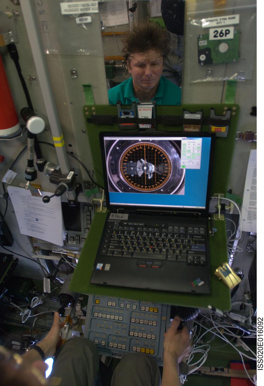
ISS020-E-016092 (1 July 2009) --- Cosmonaut Gennady Padalka (partially visible in the reflection of a mirror), Expedition 20 commander, uses an onboard laptop-based simulator in the Zvezda Service Module of the International Space Station to prepare for the relocation of the Soyuz TMA-14 spacecraft from Zvezda?s aft port to the Pirs Docking Compartment on July 2, 2009.
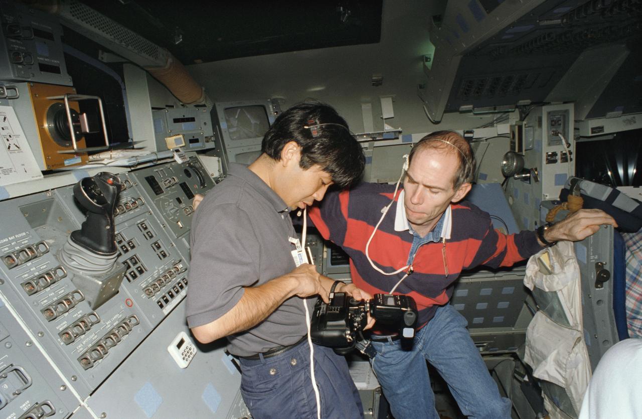
S95-12703 (May 1995) --- Astronauts Koichi Wakata (left) and Daniel T. Barry check the settings on a 35mm camera during an STS-72 training session. Wakata is a mission specialist, representing Japan's National Space Development Agency (NASDA) and Barry is a United States astronaut assigned as mission specialist for the same mission. The two are on the aft flight deck of the fixed base Shuttle Mission Simulator (SMS) at the Johnson Space Center (JSC).
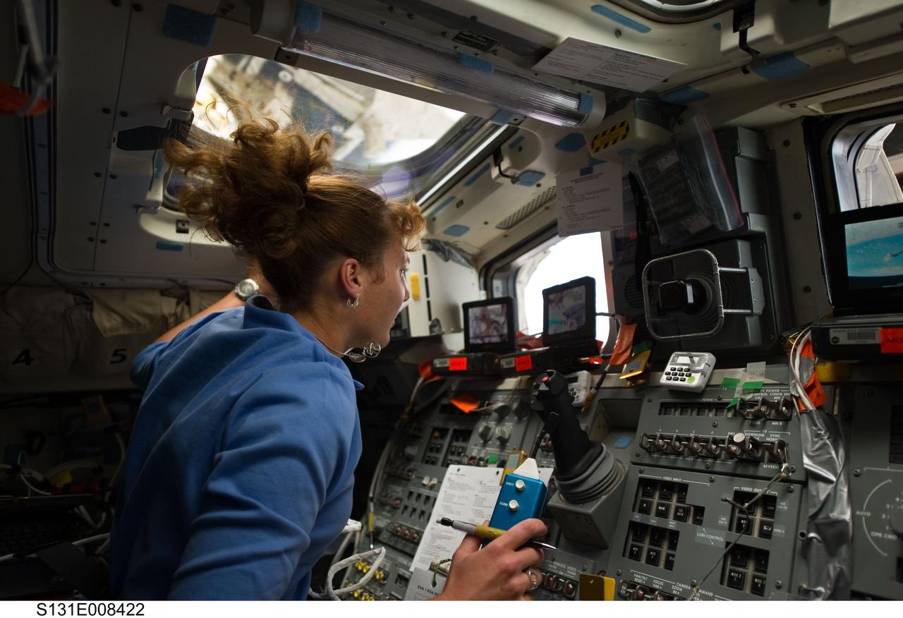
S131-E-008422 (9 April 2010) --- After many months of training in simulators, NASA astronaut Dorothy Metcalf-Lindenburger, STS-131 mission specialist, gets to put her skills to work at the controls for the shuttle Remote Manipulator System on Discovery's aft flight deck during her crew's flight day five activities. Her work is being shared with six Discovery crewmates as well as the six cosmonauts and astronauts currently assigned to the International Space Station.
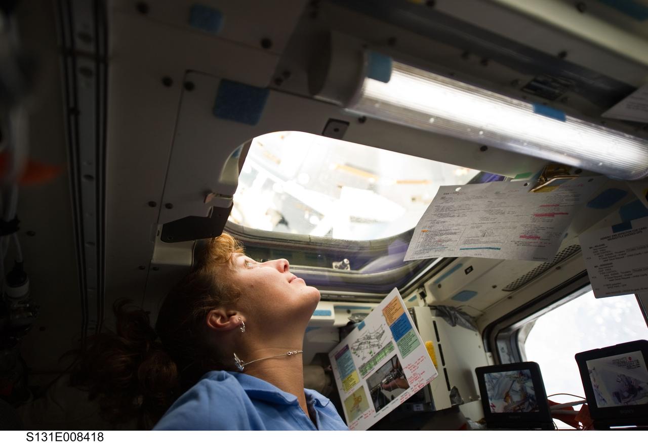
S131-E-008418 (9 April 2010) --- After many months of training in simulators, NASA astronaut Dorothy Metcalf-Lindenburger, STS-131 mission specialist, gets to put her skills to work at the controls for the shuttle Remote Manipulator System on Discovery's aft flight deck during her crew's flight day five activities. Her work is being shared with six Discovery crewmates as well as the six cosmonauts and astronauts currently assigned to the International Space Station.
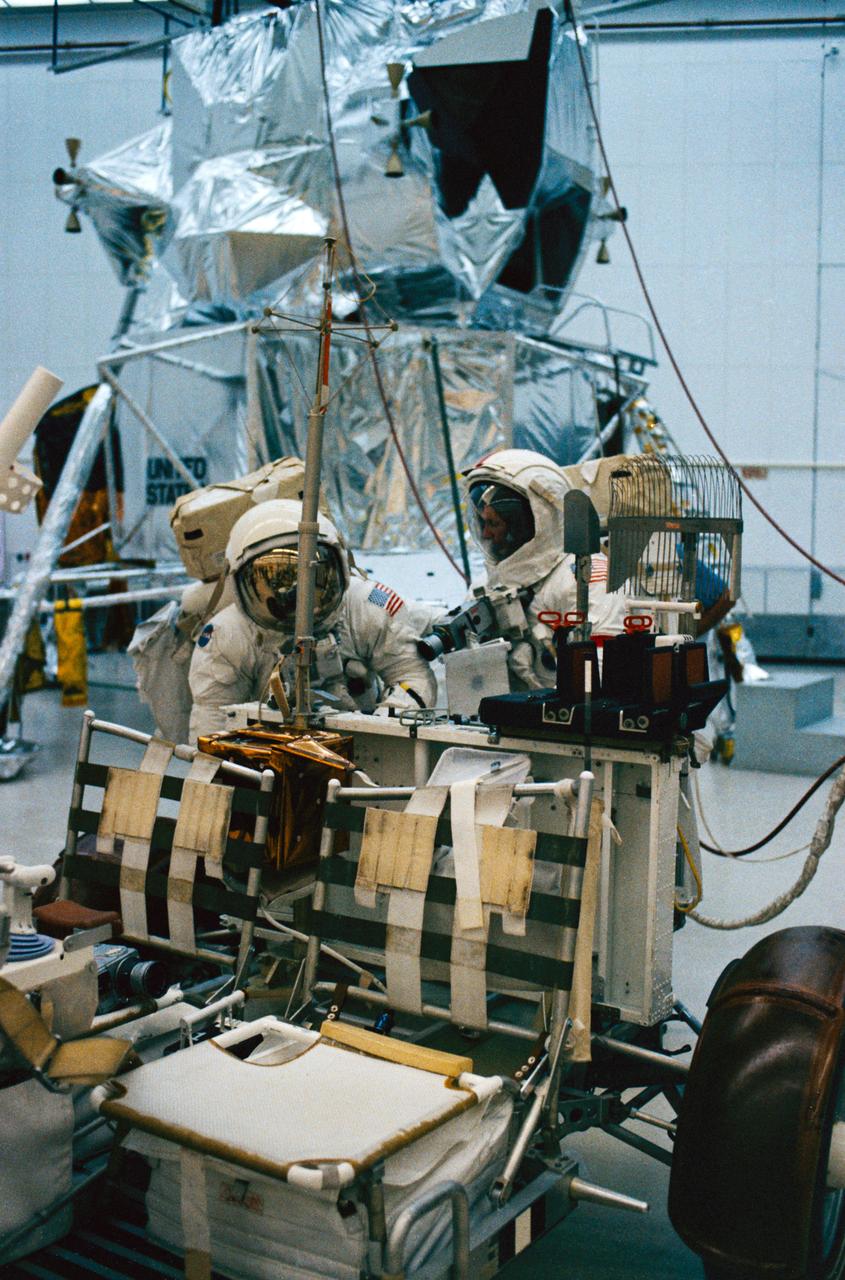
S72-48887 (September 1972) --- Astronaut Eugene A. Cernan (right), commander, and scientist-astronaut Harrison H. Schmitt, lunar module pilot, work at the aft end of a Lunar Roving Vehicle trainer during lunar surface extravehicular activity simulation training at the Kennedy Space Center (KSC), Florida. Astronauts Cernan, Schmitt, and Ronald E. Evans, command module pilot, are the prime crewmen of the Apollo 17 lunar landing mission. A Lunar Module mock-up can be seen in the background.
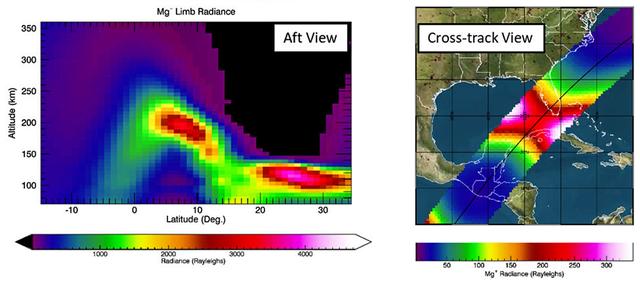
jsc2022e091371 (12/7/2022) --- A view of a simulation of the STP-H9-ECLIPSE observations of the Mg+ emission mapping scheme. The left panel (aft view) shows the observations along the orbit plane used to infer the vertical ion distribution. The right panel (cross-track view) shows the map of the Mg+ emission cross-track beneath the ISS orbit. These two data sets are simultaneously tomographically inverted to infer the 3D ion distribution. Image courtesy of the Naval Research Laboratory.
S72-48890 (September 1972) --- Scientist-astronaut Harrison H. Schmitt, lunar module pilot of the Apollo 17 lunar landing mission, procures a geological hand tool from the tool carrier at the aft end of the Lunar Roving Vehicle during lunar surface extravehicular activity simulation training at the Kennedy Space Center (KSC), Florida. Schmitt grasps a scoop with extension handle in his right hand.
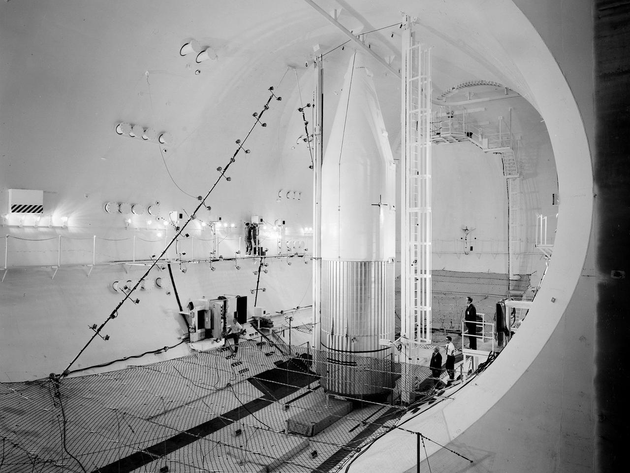
Preparations for a shroud jettison test for the Orbiting Astronomical Observatory-1 (OAO-1) satellite in the Space Power Chambers facility at the National Aeronautics and Space Administration (NASA) Lewis Research Center. The satellite was to be launched on an Atlas-Agena rocket in the spring of 1966. The 3900-pound payload was the heaviest ever attempted by Agena. The satellite was the first of three equipped with powerful telescopes to study ultraviolet data from specific stars and galaxies. In-depth observations were not possible from Earth-bound telescopes because of the filtering and distortion of the atmosphere. The OAO-1 satellite was wider in diameter than the Agena stage, so a new clamshell shroud was created to enclose both the satellite and the Agena. The clamshell shroud consisted of three sections that enclosed both the Agena and OAO-1: a fiberglass nose fairing and aluminum mid and aft fairings. The upper two fairings separated when the Atlas engines stopped, and the aft fairing fell away with the Atlas upon separation from the upper stages The large altitude tank in the Space Power Chambers could simulate altitudes up to 100,000 feet. Three shroud jettison tests were run in July 1965 and the first week of August at a simulated altitude of 20 miles. The April 8, 1966 launch from Cape Canaveral went smoothly, but the OAO-1 satellite failed after only 90 minutes due to a battery failure.
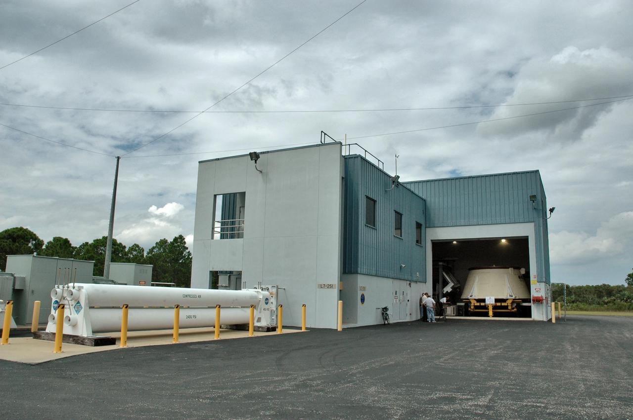
KENNEDY SPACE CENTER, FLA. - In the Assembly and Refurbishment Facility at NASA's Kennedy Space Center can be seen the solid rocket booster aft skirt designated for use on the first stage of the ARES I-1 launch vehicle being prepared for its first test flight. Ares I is the vehicle being developed for launch of the crew exploration vehicle (CEV), named Orion. Ares I-1 is currently targeted for launch from Launch Pad 39B in 2009 using the SRB first stage and a simulated second stage and simulated CEV. Ares I ascent tests and Ares I orbital tests will also take place at Kennedy at later dates. Photo credit: NASA/Jack Pfaller
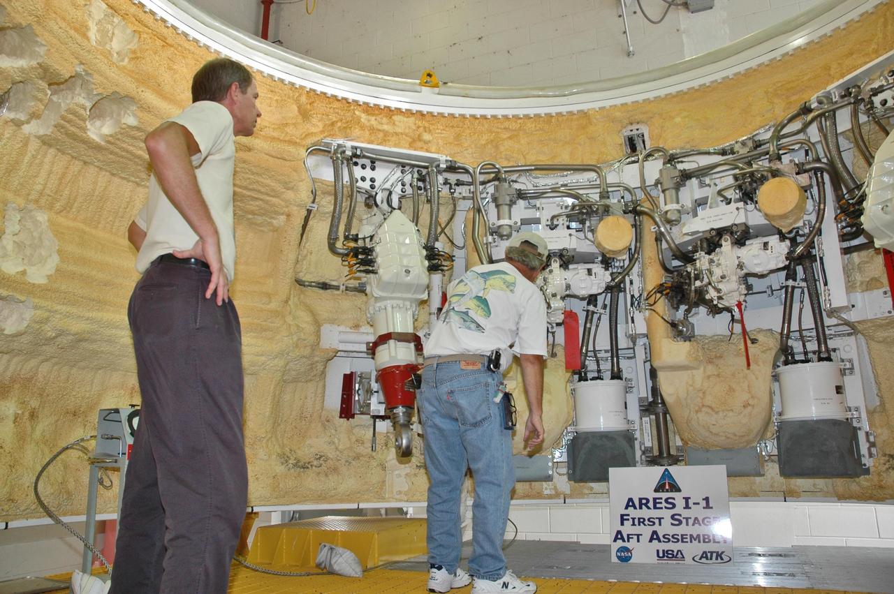
KENNEDY SPACE CENTER, FLA. - In the Assembly and Refurbishment Facility at NASA's Kennedy Space Center, workers examine some of the hardware inside the solid rocket booster aft skirt designated for use on the first stage of the ARES I-1 launch vehicle in its first test flight. Ares I is the vehicle being developed for launch of the crew exploration vehicle (CEV), named Orion. Ares I-1 is currently targeted for launch from Launch Pad 39B in 2009 using the SRB first stage and a simulated second stage and simulated CEV. Ares I ascent tests and Ares I orbital tests will also take place at Kennedy at later dates. Photo credit: NASA/Jack Pfaller
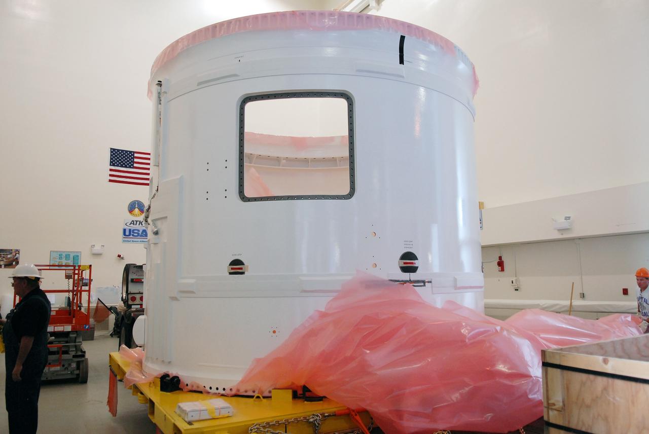
CAPE CANAVERAL, Fla. – In the Vehicle Assembly Building's extended duration orbiter lab, or EDO, at NASA's Kennedy Space Center in Florida, the Ares I-X fifth segment simulator aft section is rid of its protective cover before being moved to a stand. Ares I-X is the test vehicle for the Ares I, which is part of the Constellation Program to return men to the moon and beyond. Ares I is the essential core of a safe, reliable, cost-effective space transportation system that eventually will carry crewed missions back to the moon, on to Mars and out into the solar system. Ares I-X is targeted for launch in July 2009. Photo credit: NASA/Troy Cryder
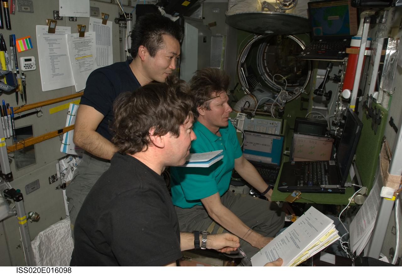
ISS020-E-016098 (1 July 2009) --- Cosmonaut Gennady Padalka (background), Expedition 20 commander; along with NASA astronaut Michael Barratt (foreground) and Japan Aerospace Exploration Agency (JAXA) astronaut Koichi Wakata, both flight engineers, use an onboard laptop-based simulator in the Zvezda Service Module of the International Space Station to prepare for the relocation of the Soyuz TMA-14 spacecraft from Zvezda?s aft port to the Pirs Docking Compartment. Padalka, Barratt and Wakata undocked the Soyuz spacecraft at 4:26 p.m. (CDT) and docked to the Pirs Docking Compartment at 4:54 p.m. on July 2, 2009.

CAPE CANAVERAL, Fla. – The Ares I-X fifth segment simulator aft section heads for the open door of the Vehicle Assembly Building at NASA's Kennedy Space Center in Florida. Ares I-X is the test vehicle for the Ares I, which is part of the Constellation Program to return men to the moon and beyond. Ares I is the essential core of a safe, reliable, cost-effective space transportation system that eventually will carry crewed missions back to the moon, on to Mars and out into the solar system. Ares I-X is targeted for launch in July 2009. Photo credit: NASA/Troy Cryder
CAPE CANAVERAL, Fla. – The Ares I-X fifth segment simulator aft section is lowered onto a stand in the Vehicle Assembly Building's extended duration orbiter lab, or EDO, at NASA's Kennedy Space Center in Florida. Ares I-X is the test vehicle for the Ares I, which is part of the Constellation Program to return men to the moon and beyond. Ares I is the essential core of a safe, reliable, cost-effective space transportation system that eventually will carry crewed missions back to the moon, on to Mars and out into the solar system. Ares I-X is targeted for launch in July 2009. Photo credit: NASA/Troy Cryder
CAPE CANAVERAL, Fla. – The Ares I-X fifth segment simulator aft section arrives in the Vehicle Assembly Building at NASA's Kennedy Space Center in Florida. Ares I-X is the test vehicle for the Ares I, which is part of the Constellation Program to return men to the moon and beyond. Ares I is the essential core of a safe, reliable, cost-effective space transportation system that eventually will carry crewed missions back to the moon, on to Mars and out into the solar system. Ares I-X is targeted for launch in July 2009. Photo credit: NASA/Troy Cryder
CAPE CANAVERAL, Fla. – The Ares I-X fifth segment simulator aft section is being transported from the Astrotech facility in Titusville, Fla., to NASA's Kennedy Space Center in Florida. Ares I-X is the test vehicle for the Ares I, which is part of the Constellation Program to return men to the moon and beyond. Ares I is the essential core of a safe, reliable, cost-effective space transportation system that eventually will carry crewed missions back to the moon, on to Mars and out into the solar system. Ares I-X is targeted for launch in July 2009. Photo credit: NASA/Troy Cryder
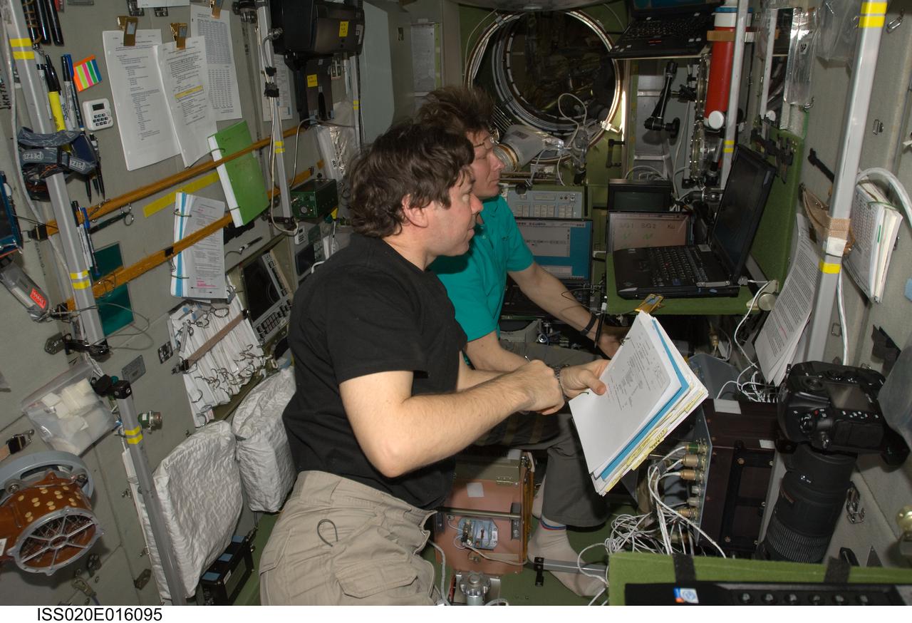
ISS020-E-016095 (1 July 2009) --- Cosmonaut Gennady Padalka (background), Expedition 20 commander; and NASA astronaut Michael Barratt, flight engineer, use an onboard laptop-based simulator in the Zvezda Service Module of the International Space Station to prepare for the relocation of the Soyuz TMA-14 spacecraft from Zvezda?s aft port to the Pirs Docking Compartment. Padalka and Barratt, along with Japan Aerospace Exploration Agency (JAXA) astronaut Koichi Wakata (out of frame), flight engineer, undocked the Soyuz spacecraft at 4:26 p.m. (CDT) and docked to the Pirs Docking Compartment at 4:54 p.m. on July 2, 2009.
STS-56 Discovery, Orbiter Vehicle (OV) 103, Commander Kenneth Cameron, (left) and Pilot Stephen S. Oswald, wearing launch and entry suits (LESs) and launch and entry helmets (LEHs), are seated on the forward flight deck of the crew compartment trainer (CCT), a shuttle mockup. Cameron mans the commander station controls and Oswald the pilots station controls during an emergency egress (bailout) simulation. The view was taken from the aft flight deck looking forward and includes Cameron's and Oswald's profiles and the forward flight deck controls and checklists. The CCT is located in JSC's Mockup and Integration Laboratory (MAIL) Bldg 9NE.
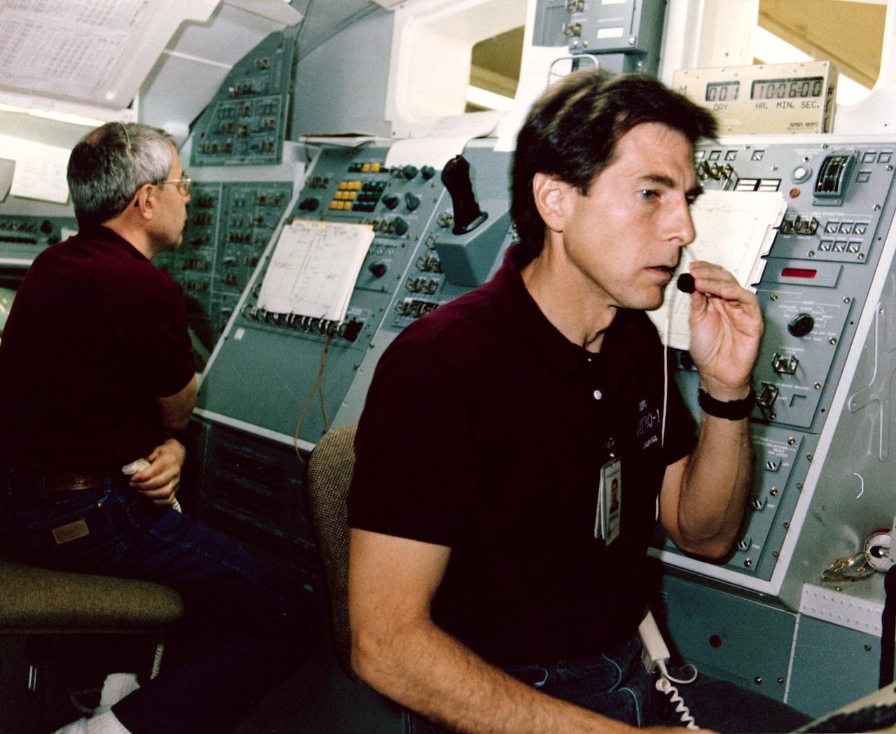
STS-35 Mission Specialist (MS) Robert A.R. Parker (left) and Payload Specialist Samuel T. Durrance practice Astronomy Laboratory 1 (ASTRO-1) experiment procedures in a space shuttle aft flight deck mockup in the Payload Crew Training Complex at the Marshall Space Flight Center (MSFC) in Huntsville, Alabama. For all Spacelab missions, shuttle crew members train regularly in the facility in preparation to operate experiments on their Spacelab missions. The ASTRO-1 crew will operate the ultraviolet telescopes and instrument pointing system (IPS) from Columbia's, Orbiter Vehicle (OV) 102's, aft flight deck. The seven-member ASTRO-1 crew will work around the clock, in 12-hour shifts, to allow the maximum number of observations to be made during their nine or ten days in orbit. In addition to the commander and pilot, the crew consistss of three MSs and two payload specialists. (MSs are career astronauts who are trained in a specialized field. Payload specialists are members of the science investigator teams who were nominated by their peers to operate their experiments on orbit. They are trained and certified for flight by NASA.) View provided by MSFC with alternate number 9005803.
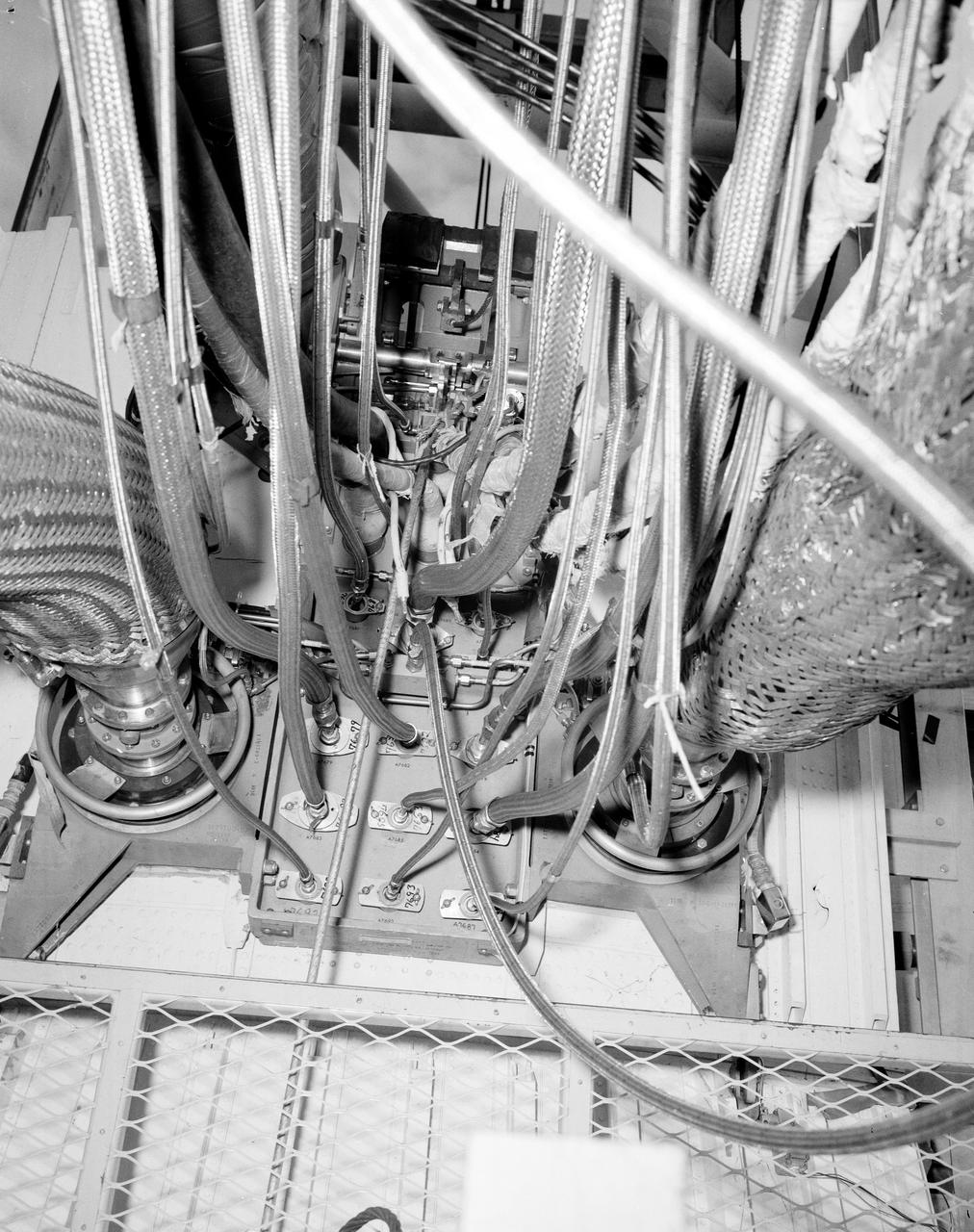
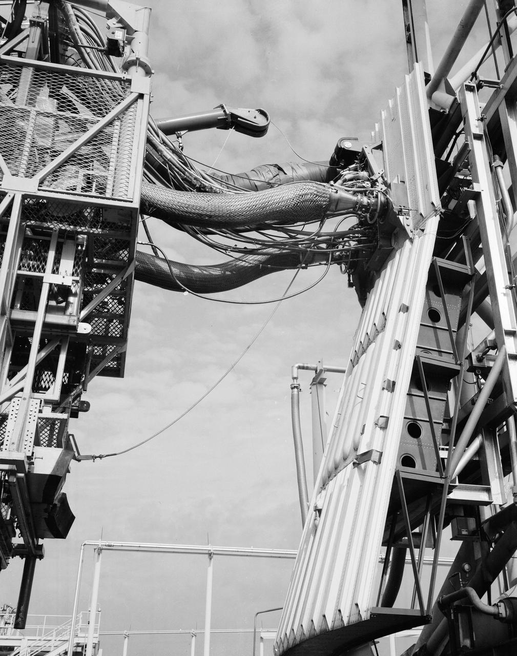
The Marshall Space Flight Center (MSFC) played a crucial role in the development of the huge Saturn rockets that delivered humans to the moon in the 1960s. Many unique facilities existed at MSFC for the development and testing of the Saturn rockets. Affectionately nicknamed “The Arm Farm”, the Random Motion/ liftoff Simulator was one of those unique facilities. This facility was developed to test the swing arm mechanisms that were used to hold the rocket in position until liftoff. The Arm Farm provided the capability of testing the detachment and reconnection of various arms under brutally realistic conditions. The 18-acre facility consisted of more than a half dozen arm test positions and one position for testing access arms used by the Apollo astronauts. Each test position had two elements: a vehicle simulator for duplicating motions during countdown and launch; and a section duplicating the launch tower. The vehicle simulator duplicated the portion of the vehicle skin that contained the umbilical connections and personnel access hatches. Driven by a hydraulic servo system, the vehicle simulator produced relative motion between the vehicle and tower. On the Arm Farm, extreme environmental conditions (such as a launch scrub during an approaching Florida thunderstorm) could be simulated. The dramatic scenes that the Marshall engineers and technicians created at the Arm Farm permitted the gathering of crucial technical and engineering data to ensure a successful real time launch from the Kennedy Space Center. This photo depicts a general view of the S-IV-B aft swing arm umbilical carrier line tray modification.
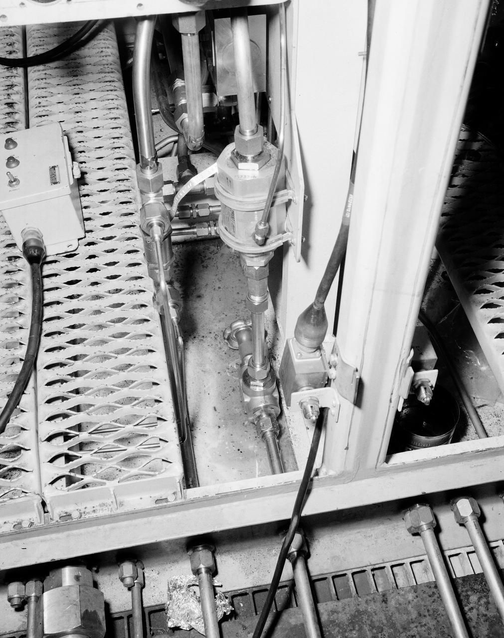
The Marshall Space Flight Center (MSFC) played a crucial role in the development of the huge Saturn rockets that delivered humans to the moon in the 1960s. Many unique facilities existed at MSFC for the development and testing of the Saturn rockets. Affectionately nicknamed “The Arm Farm”, the Random Motion/ Lift-Off Simulator was one of those unique facilities. This facility was developed to test the swing arm mechanisms that were used to hold the rocket in position until liftoff. The Arm Farm provided the capability of testing the detachment and reconnection of various arms under brutally realistic conditions. The 18-acre facility consisted of more than a half dozen arm test positions and one position for testing access arms used by the Apollo astronauts. Each test position had two elements: a vehicle simulator for duplicating motions during countdown and launch; and a section duplicating the launch tower. The vehicle simulator duplicated the portion of the vehicle skin that contained the umbilical connections and personnel access hatches. Driven by a hydraulic servo system, the vehicle simulator produced relative motion between the vehicle and tower. On the Arm Farm, extreme environmental conditions (such as a launch scrub during an approaching Florida thunderstorm) could be simulated. The dramatic scenes that the Marshall engineers and technicians created at the Arm Farm permitted the gathering of crucial technical and engineering data to ensure a successful real time launch from the Kennedy Space Center. This photo depicts a close up view of the S-IV-B aft swing arm hydraulic with drain system orifice valve.
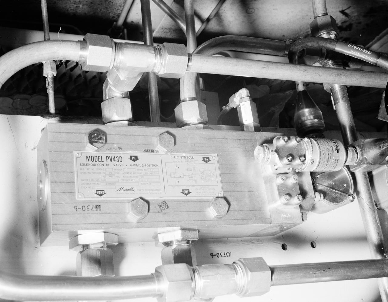
The Marshall Space Flight Center (MSFC) played a crucial role in the development of the huge Saturn rockets that delivered humans to the moon in the 1960s. Many unique facilities existed at MSFC for the development and testing of the Saturn rockets. Affectionately nicknamed “The Arm Farm”, the Random Motion/ liftoff Simulator was one of those unique facilities. This facility was developed to test the swing arm mechanisms that were used to hold the rocket in position until liftoff. The Arm Farm provided the capability of testing the detachment and reconnection of various arms under brutally realistic conditions. The 18-acre facility consisted of more than a half dozen arm test positions and one position for testing access arms used by the Apollo astronauts. Each test position had two elements: a vehicle simulator for duplicating motions during countdown and launch; and a section duplicating the launch tower. The vehicle simulator duplicated the portion of the vehicle skin that contained the umbilical connections and personnel access hatches. Driven by a hydraulic servo system, the vehicle simulator produced relative motion between the vehicle and tower. On the Arm Farm, extreme environmental conditions (such as a launch scrub during an approaching Florida thunderstorm) could be simulated. The dramatic scenes that the Marshall engineers and technicians created at the Arm Farm permitted the gathering of crucial technical and engineering data to ensure a successful real time launch from the Kennedy Space Center. This photo depicts a close up of the S-IV-B aft swing arm orifice on the PV 43D soloniod valve.
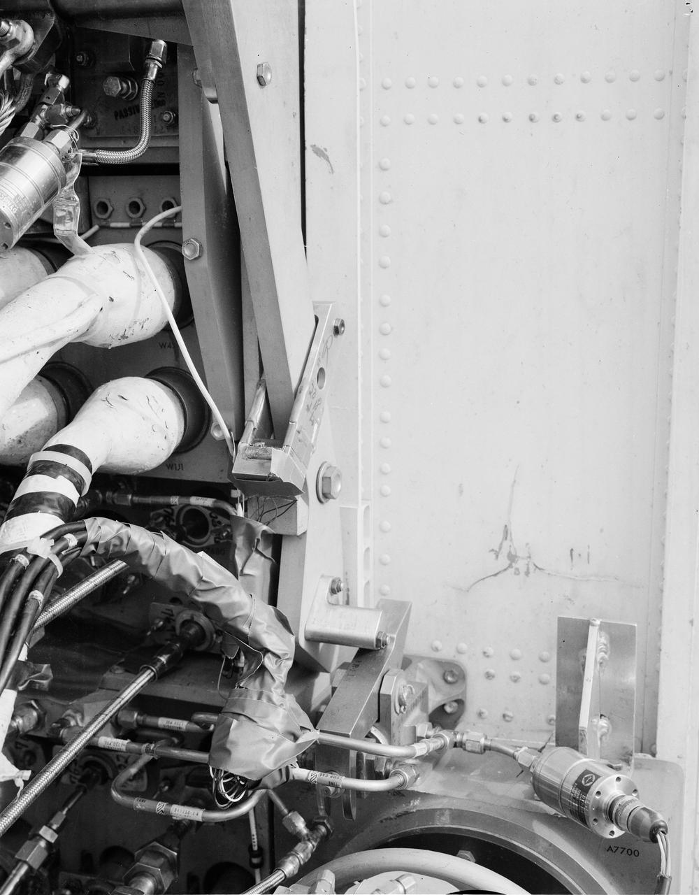
The Marshall Space Flight Center (MSFC) played a crucial role in the development of the huge Saturn rockets that delivered humans to the moon in the 1960s. Many unique facilities existed at MSFC for the development and testing of the Saturn rockets. Affectionately nicknamed “The Arm Farm”, the Random Motion/ Lift-Off Simulator was one of those unique facilities. This facility was developed to test the swing arm mechanisms that were used to hold the rocket in position until liftoff. The Arm Farm provided the capability of testing the detachment and reconnection of various arms under brutally realistic conditions. The 18-acre facility consisted of more than a half dozen arm test positions and one position for testing access arms used by the Apollo astronauts. Each test position had two elements: a vehicle simulator for duplicating motions during countdown and launch; and a section duplicating the launch tower. The vehicle simulator duplicated the portion of the vehicle skin that contained the umbilical connections and personnel access hatches. Driven by a hydraulic servo system, the vehicle simulator produced relative motion between the vehicle and tower. On the Arm Farm, extreme environmental conditions (such as a launch scrub during an approaching Florida thunderstorm) could be simulated. The dramatic scenes that the Marshall engineers and technicians created at the Arm Farm permitted the gathering of crucial technical and engineering data to ensure a successful real time launch from the Kennedy Space Center. This photo depicts a close up of the S-IV-B Aft Swing Arm static and lanyard carrier.
The Marshall Space Flight Center (MSFC) played a crucial role in the development of the huge Saturn rockets that delivered humans to the moon in the 1960s. Many unique facilities existed at MSFC for the development and testing of the Saturn rockets. Affectionately nicknamed “The Arm Farm”, the Random Motion/ Lift-Off Simulator was one of those unique facilities. This facility was developed to test the swing arm mechanisms that were used to hold the rocket in position until liftoff. The Arm Farm provided the capability of testing the detachment and reconnection of various arms under brutally realistic conditions. The 18-acre facility consisted of more than a half dozen arm test positions and one position for testing access arms used by the Apollo astronauts. Each test position had two elements: a vehicle simulator for duplicating motions during countdown and launch; and a section duplicating the launch tower. The vehicle simulator duplicated the portion of the vehicle skin that contained the umbilical connections and personnel access hatches. Driven by a hydraulic servo system, the vehicle simulator produced relative motion between the vehicle and tower. On the Arm Farm, extreme environmental conditions (such as a launch scrub during an approaching Florida thunderstorm) could be simulated. The dramatic scenes that the Marshall engineers and technicians created at the Arm Farm permitted the gathering of crucial technical and engineering data to ensure a successful real time launch from the Kennedy Space Center. This photo depicts a close up of the S-IV-B aft swing arm cam lever stop strain guage.

At Vandenberg Air Force Base in California, technicians prepare to mate the AIM spacecraft (at left) to the SoftRide isolation system on the Orbital Sciences Pegasus XL rocket. The Cosmic Dust Experiment surfaces can be clearly seen as 12 rectangular areas on the aft portion of the spacecraft. AIM, which stands for Aeronomy of Ice in the Mesosphere, is being prepared for integrated testing and a flight simulation. The AIM spacecraft will fly three instruments designed to study polar mesospheric clouds located at the edge of space, 50 miles above the Earth's surface in the coldest part of the planet's atmosphere. The mission's primary goal is to explain why these clouds form and what has caused them to become brighter and more numerous and appear at lower latitudes in recent years. AIM's results will provide the basis for the study of long-term variability in the mesospheric climate and its relationship to global climate change. Launch from the Pegasus XL rocket is scheduled for April 25.

KENNEDY SPACE CENTER, FLA. -- At Vandenberg Air Force Base in California, technicians prepare to mate the AIM spacecraft (at left) to the SoftRide isolation system on the Orbital Sciences Pegasus XL rocket. The Cosmic Dust Experiment surfaces can be clearly seen as 12 rectangular areas on the aft portion of the spacecraft. AIM, which stands for Aeronomy of Ice in the Mesosphere, is being prepared for integrated testing and a flight simulation. The AIM spacecraft will fly three instruments designed to study polar mesospheric clouds located at the edge of space, 50 miles above the Earth's surface in the coldest part of the planet's atmosphere. The mission's primary goal is to explain why these clouds form and what has caused them to become brighter and more numerous and appear at lower latitudes in recent years. AIM's results will provide the basis for the study of long-term variability in the mesospheric climate and its relationship to global climate change. Launch from the Pegasus XL rocket is scheduled for April 25.
The liquid hydrogen tank that will be part of the Space Launch System rocket’s core stage is being prepared for the Artemis III mission at NASA’s Michoud Assembly Facility in New Orleans. Eventually, the tank will be connected to the engine section that will house the four RS-25 engines. Once the aft simulator is attached, the LH2 tank undergoes non-destructive evaluation, which will test weld strength and ensure the tank is structurally sound. The SLS core stage is made up of five unique elements: the forward skirt, liquid oxygen tank, intertank, liquid hydrogen tank, and the engine section. The tank holds 537,000 gallons of liquid hydrogen cooled to minus 432 degrees Fahrenheit and sits between the core stage’s intertank and engine section. The liquid hydrogen hardware, along with the liquid oxygen tank, will provide propellant to the four RS-25 engines at the bottom of the core stage to produce more than two million pounds of thrust to help launch the Artemis III mission to the Moon. Together with its four RS-25 engines, the rocket’s massive 212-foot-tall core stage — the largest stage NASA has ever built — and its twin solid rocket boosters will produce 8.8 million pounds of thrust to send NASA’s Orion spacecraft, astronauts and supplies beyond Earth’s orbit to the Moon.
The liquid hydrogen tank that will be part of the Space Launch System rocket’s core stage is being prepared for the Artemis III mission at NASA’s Michoud Assembly Facility in New Orleans. Eventually, the tank will be connected to the engine section that will house the four RS-25 engines. Once the aft simulator is attached, the LH2 tank undergoes non-destructive evaluation, which will test weld strength and ensure the tank is structurally sound. The SLS core stage is made up of five unique elements: the forward skirt, liquid oxygen tank, intertank, liquid hydrogen tank, and the engine section. The tank holds 537,000 gallons of liquid hydrogen cooled to minus 432 degrees Fahrenheit and sits between the core stage’s intertank and engine section. The liquid hydrogen hardware, along with the liquid oxygen tank, will provide propellant to the four RS-25 engines at the bottom of the core stage to produce more than two million pounds of thrust to help launch the Artemis III mission to the Moon. Together with its four RS-25 engines, the rocket’s massive 212-foot-tall core stage — the largest stage NASA has ever built — and its twin solid rocket boosters will produce 8.8 million pounds of thrust to send NASA’s Orion spacecraft, astronauts and supplies beyond Earth’s orbit to the Moon.
The liquid hydrogen tank that will be part of the Space Launch System rocket’s core stage is being prepared for the Artemis III mission at NASA’s Michoud Assembly Facility in New Orleans. Eventually, the tank will be connected to the engine section that will house the four RS-25 engines. Once the aft simulator is attached, the LH2 tank undergoes non-destructive evaluation, which will test weld strength and ensure the tank is structurally sound. The SLS core stage is made up of five unique elements: the forward skirt, liquid oxygen tank, intertank, liquid hydrogen tank, and the engine section. The tank holds 537,000 gallons of liquid hydrogen cooled to minus 432 degrees Fahrenheit and sits between the core stage’s intertank and engine section. The liquid hydrogen hardware, along with the liquid oxygen tank, will provide propellant to the four RS-25 engines at the bottom of the core stage to produce more than two million pounds of thrust to help launch the Artemis III mission to the Moon. Together with its four RS-25 engines, the rocket’s massive 212-foot-tall core stage — the largest stage NASA has ever built — and its twin solid rocket boosters will produce 8.8 million pounds of thrust to send NASA’s Orion spacecraft, astronauts and supplies beyond Earth’s orbit to the Moon.
The liquid hydrogen tank that will be part of the Space Launch System rocket’s core stage is being prepared for the Artemis III mission at NASA’s Michoud Assembly Facility in New Orleans. Eventually, the tank will be connected to the engine section that will house the four RS-25 engines. Once the aft simulator is attached, the LH2 tank undergoes non-destructive evaluation, which will test weld strength and ensure the tank is structurally sound. The SLS core stage is made up of five unique elements: the forward skirt, liquid oxygen tank, intertank, liquid hydrogen tank, and the engine section. The tank holds 537,000 gallons of liquid hydrogen cooled to minus 432 degrees Fahrenheit and sits between the core stage’s intertank and engine section. The liquid hydrogen hardware, along with the liquid oxygen tank, will provide propellant to the four RS-25 engines at the bottom of the core stage to produce more than two million pounds of thrust to help launch the Artemis III mission to the Moon. Together with its four RS-25 engines, the rocket’s massive 212-foot-tall core stage — the largest stage NASA has ever built — and its twin solid rocket boosters will produce 8.8 million pounds of thrust to send NASA’s Orion spacecraft, astronauts and supplies beyond Earth’s orbit to the Moon.
The liquid hydrogen tank that will be part of the Space Launch System rocket’s core stage is being prepared for the Artemis III mission at NASA’s Michoud Assembly Facility in New Orleans. Eventually, the tank will be connected to the engine section that will house the four RS-25 engines. Once the aft simulator is attached, the LH2 tank undergoes non-destructive evaluation, which will test weld strength and ensure the tank is structurally sound. The SLS core stage is made up of five unique elements: the forward skirt, liquid oxygen tank, intertank, liquid hydrogen tank, and the engine section. The tank holds 537,000 gallons of liquid hydrogen cooled to minus 432 degrees Fahrenheit and sits between the core stage’s intertank and engine section. The liquid hydrogen hardware, along with the liquid oxygen tank, will provide propellant to the four RS-25 engines at the bottom of the core stage to produce more than two million pounds of thrust to help launch the Artemis III mission to the Moon. Together with its four RS-25 engines, the rocket’s massive 212-foot-tall core stage — the largest stage NASA has ever built — and its twin solid rocket boosters will produce 8.8 million pounds of thrust to send NASA’s Orion spacecraft, astronauts and supplies beyond Earth’s orbit to the Moon.
The liquid hydrogen tank that will be part of the Space Launch System rocket’s core stage is being prepared for the Artemis III mission at NASA’s Michoud Assembly Facility in New Orleans. Eventually, the tank will be connected to the engine section that will house the four RS-25 engines. Once the aft simulator is attached, the LH2 tank undergoes non-destructive evaluation, which will test weld strength and ensure the tank is structurally sound. The SLS core stage is made up of five unique elements: the forward skirt, liquid oxygen tank, intertank, liquid hydrogen tank, and the engine section. The tank holds 537,000 gallons of liquid hydrogen cooled to minus 432 degrees Fahrenheit and sits between the core stage’s intertank and engine section. The liquid hydrogen hardware, along with the liquid oxygen tank, will provide propellant to the four RS-25 engines at the bottom of the core stage to produce more than two million pounds of thrust to help launch the Artemis III mission to the Moon. Together with its four RS-25 engines, the rocket’s massive 212-foot-tall core stage — the largest stage NASA has ever built — and its twin solid rocket boosters will produce 8.8 million pounds of thrust to send NASA’s Orion spacecraft, astronauts and supplies beyond Earth’s orbit to the Moon.
The liquid hydrogen tank that will be part of the Space Launch System rocket’s core stage is being prepared for the Artemis III mission at NASA’s Michoud Assembly Facility in New Orleans. Eventually, the tank will be connected to the engine section that will house the four RS-25 engines. Once the aft simulator is attached, the LH2 tank undergoes non-destructive evaluation, which will test weld strength and ensure the tank is structurally sound. The SLS core stage is made up of five unique elements: the forward skirt, liquid oxygen tank, intertank, liquid hydrogen tank, and the engine section. The tank holds 537,000 gallons of liquid hydrogen cooled to minus 432 degrees Fahrenheit and sits between the core stage’s intertank and engine section. The liquid hydrogen hardware, along with the liquid oxygen tank, will provide propellant to the four RS-25 engines at the bottom of the core stage to produce more than two million pounds of thrust to help launch the Artemis III mission to the Moon. Together with its four RS-25 engines, the rocket’s massive 212-foot-tall core stage — the largest stage NASA has ever built — and its twin solid rocket boosters will produce 8.8 million pounds of thrust to send NASA’s Orion spacecraft, astronauts and supplies beyond Earth’s orbit to the Moon.
The liquid hydrogen tank that will be part of the Space Launch System rocket’s core stage is being prepared for the Artemis III mission at NASA’s Michoud Assembly Facility in New Orleans. Eventually, the tank will be connected to the engine section that will house the four RS-25 engines. Once the aft simulator is attached, the LH2 tank undergoes non-destructive evaluation, which will test weld strength and ensure the tank is structurally sound. The SLS core stage is made up of five unique elements: the forward skirt, liquid oxygen tank, intertank, liquid hydrogen tank, and the engine section. The tank holds 537,000 gallons of liquid hydrogen cooled to minus 432 degrees Fahrenheit and sits between the core stage’s intertank and engine section. The liquid hydrogen hardware, along with the liquid oxygen tank, will provide propellant to the four RS-25 engines at the bottom of the core stage to produce more than two million pounds of thrust to help launch the Artemis III mission to the Moon. Together with its four RS-25 engines, the rocket’s massive 212-foot-tall core stage — the largest stage NASA has ever built — and its twin solid rocket boosters will produce 8.8 million pounds of thrust to send NASA’s Orion spacecraft, astronauts and supplies beyond Earth’s orbit to the Moon.
The liquid hydrogen tank that will be part of the Space Launch System rocket’s core stage is being prepared for the Artemis III mission at NASA’s Michoud Assembly Facility in New Orleans. Eventually, the tank will be connected to the engine section that will house the four RS-25 engines. Once the aft simulator is attached, the LH2 tank undergoes non-destructive evaluation, which will test weld strength and ensure the tank is structurally sound. The SLS core stage is made up of five unique elements: the forward skirt, liquid oxygen tank, intertank, liquid hydrogen tank, and the engine section. The tank holds 537,000 gallons of liquid hydrogen cooled to minus 432 degrees Fahrenheit and sits between the core stage’s intertank and engine section. The liquid hydrogen hardware, along with the liquid oxygen tank, will provide propellant to the four RS-25 engines at the bottom of the core stage to produce more than two million pounds of thrust to help launch the Artemis III mission to the Moon. Together with its four RS-25 engines, the rocket’s massive 212-foot-tall core stage — the largest stage NASA has ever built — and its twin solid rocket boosters will produce 8.8 million pounds of thrust to send NASA’s Orion spacecraft, astronauts and supplies beyond Earth’s orbit to the Moon.

The liquid hydrogen tank that will be part of the Space Launch System rocket’s core stage is being prepared for the Artemis III mission at NASA’s Michoud Assembly Facility in New Orleans. Eventually, the tank will be connected to the engine section that will house the four RS-25 engines. Once the aft simulator is attached, the LH2 tank undergoes non-destructive evaluation, which will test weld strength and ensure the tank is structurally sound. The SLS core stage is made up of five unique elements: the forward skirt, liquid oxygen tank, intertank, liquid hydrogen tank, and the engine section. The tank holds 537,000 gallons of liquid hydrogen cooled to minus 432 degrees Fahrenheit and sits between the core stage’s intertank and engine section. The liquid hydrogen hardware, along with the liquid oxygen tank, will provide propellant to the four RS-25 engines at the bottom of the core stage to produce more than two million pounds of thrust to help launch the Artemis III mission to the Moon. Together with its four RS-25 engines, the rocket’s massive 212-foot-tall core stage — the largest stage NASA has ever built — and its twin solid rocket boosters will produce 8.8 million pounds of thrust to send NASA’s Orion spacecraft, astronauts and supplies beyond Earth’s orbit to the Moon.
The liquid hydrogen tank that will be part of the Space Launch System rocket’s core stage is being prepared for the Artemis III mission at NASA’s Michoud Assembly Facility in New Orleans. Eventually, the tank will be connected to the engine section that will house the four RS-25 engines. Once the aft simulator is attached, the LH2 tank undergoes non-destructive evaluation, which will test weld strength and ensure the tank is structurally sound. The SLS core stage is made up of five unique elements: the forward skirt, liquid oxygen tank, intertank, liquid hydrogen tank, and the engine section. The tank holds 537,000 gallons of liquid hydrogen cooled to minus 432 degrees Fahrenheit and sits between the core stage’s intertank and engine section. The liquid hydrogen hardware, along with the liquid oxygen tank, will provide propellant to the four RS-25 engines at the bottom of the core stage to produce more than two million pounds of thrust to help launch the Artemis III mission to the Moon. Together with its four RS-25 engines, the rocket’s massive 212-foot-tall core stage — the largest stage NASA has ever built — and its twin solid rocket boosters will produce 8.8 million pounds of thrust to send NASA’s Orion spacecraft, astronauts and supplies beyond Earth’s orbit to the Moon.
The liquid hydrogen tank that will be part of the Space Launch System rocket’s core stage is being prepared for the Artemis III mission at NASA’s Michoud Assembly Facility in New Orleans. Eventually, the tank will be connected to the engine section that will house the four RS-25 engines. Once the aft simulator is attached, the LH2 tank undergoes non-destructive evaluation, which will test weld strength and ensure the tank is structurally sound. The SLS core stage is made up of five unique elements: the forward skirt, liquid oxygen tank, intertank, liquid hydrogen tank, and the engine section. The tank holds 537,000 gallons of liquid hydrogen cooled to minus 432 degrees Fahrenheit and sits between the core stage’s intertank and engine section. The liquid hydrogen hardware, along with the liquid oxygen tank, will provide propellant to the four RS-25 engines at the bottom of the core stage to produce more than two million pounds of thrust to help launch the Artemis III mission to the Moon. Together with its four RS-25 engines, the rocket’s massive 212-foot-tall core stage — the largest stage NASA has ever built — and its twin solid rocket boosters will produce 8.8 million pounds of thrust to send NASA’s Orion spacecraft, astronauts and supplies beyond Earth’s orbit to the Moon.
The liquid hydrogen tank that will be part of the Space Launch System rocket’s core stage is being prepared for the Artemis III mission at NASA’s Michoud Assembly Facility in New Orleans. Eventually, the tank will be connected to the engine section that will house the four RS-25 engines. Once the aft simulator is attached, the LH2 tank undergoes non-destructive evaluation, which will test weld strength and ensure the tank is structurally sound. The SLS core stage is made up of five unique elements: the forward skirt, liquid oxygen tank, intertank, liquid hydrogen tank, and the engine section. The tank holds 537,000 gallons of liquid hydrogen cooled to minus 432 degrees Fahrenheit and sits between the core stage’s intertank and engine section. The liquid hydrogen hardware, along with the liquid oxygen tank, will provide propellant to the four RS-25 engines at the bottom of the core stage to produce more than two million pounds of thrust to help launch the Artemis III mission to the Moon. Together with its four RS-25 engines, the rocket’s massive 212-foot-tall core stage — the largest stage NASA has ever built — and its twin solid rocket boosters will produce 8.8 million pounds of thrust to send NASA’s Orion spacecraft, astronauts and supplies beyond Earth’s orbit to the Moon.
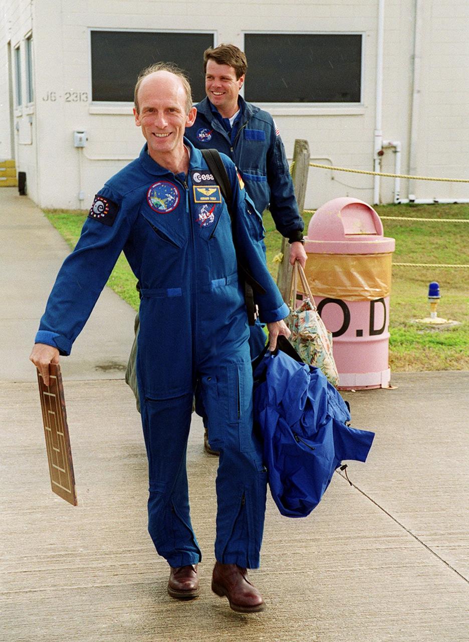
STS-99 Mission Specialist Gerhard Thiele (foreground) and Commander Kevin Kregel make their way to the runway at the Shuttle Landing Facility for a return flight to Houston. During the Jan. 31 launch countdown, Endeavour's enhanced master events controller (E-MEC) No. 2 failed a standard preflight test. Launch was postponed and Shuttle managers decided to replace the E-MEC located in the orbiter's aft compartment. Launch controllers will be in a position to begin the STS-99 countdown the morning of Feb. 6 and ready to support a launch midto late next week pending availability of the Eastern Range. The postponed launch gives the crew an opportunity for more training and time with their families. Known as the Shuttle Radar Topography Mission, it will chart a new course to produce unrivaled 3-D images of the Earth's surface, using two antennae and a 200-foot-long section of space station-derived mast protruding from the payload bay. The result could be close to 1 trillion measurements of the Earth's topography. Besides contributing to the production of better maps, these measurements could lead to improved water drainage modeling, more realistic flight simulators, better locations for cell phone towers, and enhanced navigation safety

STS-99 Mission Specialist Mamoru Mohri of Japan and his wife, Akiko, wave before their departure from Patrick Air Force Base and return to Houston. With the postponement of the launch of STS-99 on Jan. 31, the crew have an opportunity for more training and time with their families. During the launch countdown, Endeavour's enhanced master events controller (E-MEC) No. 2 failed a standard preflight test. Launch was postponed and Shuttle managers decided to replace the E-MEC located in the orbiter's aft compartment. Launch controllers will be in a position to begin the STS-99 countdown the morning of Feb. 6 and ready to support a launch midto late next week pending availability of the Eastern Range. Known as the Shuttle Radar Topography Mission, it will chart a new course to produce unrivaled 3-D images of the Earth's surface, using two antennae and a 200-foot-long section of space station-derived mast protruding from the payload bay. The result could be close to 1 trillion measurements of the Earth's topography. Besides contributing to the production of better maps, these measurements could lead to improved water drainage modeling, more realistic flight simulators, better locations for cell phone towers, and enhanced navigation safety
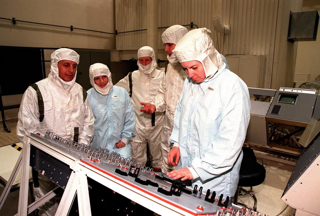
In the Vertical Processing Facility (VPF), the STS-93 crew stands in front of the VPF Aft Flight Deck simulator, which is part of KSC's Cargo Integration Test Equipment. From left, they are Mission Specialist Michel Tognini of France, Commander Eileen M. Collins, Mission Specialist Steven A. Hawley, Pilot Jeffrey S. Ashby and Mission Specialist Catherine G. Coleman. Tognini represents France's space agency, the Centre National d'Etudes Spatiales (CNES). STS-93, scheduled to launch July 9 aboard Space Shuttle Columbia, has the primary mission of the deployment of the Chandra X-ray Observatory, which is undergoing testing in the VPF. Formerly called the Advanced X-ray Astrophysics Facility, Chandra comprises three major elements: the spacecraft, the science instrument module (SIM), and the world's most powerful X-ray telescope. Chandra will allow scientists from around the world to see previously invisible black holes and high-temperature gas clouds, giving the observatory the potential to rewrite the books on the structure and evolution of our universe

On the runway at the Shuttle Landing Facility, STS-99 crew members Pilot Dominic Gorie, Mission Specialist Janice Voss, Commander Kevin Kregel and Mission Specialist Gerhard Thiele discuss departure plans to Houston. Kregel and Gorie will be piloting T-38 jets with Voss and Thiele as passengers. During the Jan. 31 launch countdown, Endeavour's enhanced master events controller (E-MEC) No. 2 failed a standard preflight test. Launch was postponed and Shuttle managers decided to replace the E-MEC located in the orbiter's aft compartment. Launch controllers will be in a position to begin the STS-99 countdown the morning of Feb. 6 and ready to support a launch midto latenext week pending availability of the Eastern Range. The postponed launch gives the crew an opportunity for more training and time with their families. Known as the Shuttle Radar Topography Mission, it will chart a new course to produce unrivaled 3-D images of the Earth's surface, using two antennae and a 200-foot-long section of space station-derived mast protruding from the payload bay. The result could be close to 1 trillion measurements of the Earth's topography. Besides contributing to the production of better maps, these measurements could lead to improved water drainage modeling, more realistic flight simulators, better locations for cell phone towers, and enhanced navigation safety

STS-99 Mission Specialist Gerhard Thiele (foreground) and Commander Kevin Kregel make their way to the runway at the Shuttle Landing Facility for a return flight to Houston. During the Jan. 31 launch countdown, Endeavour's enhanced master events controller (E-MEC) No. 2 failed a standard preflight test. Launch was postponed and Shuttle managers decided to replace the E-MEC located in the orbiter's aft compartment. Launch controllers will be in a position to begin the STS-99 countdown the morning of Feb. 6 and ready to support a launch midto late next week pending availability of the Eastern Range. The postponed launch gives the crew an opportunity for more training and time with their families. Known as the Shuttle Radar Topography Mission, it will chart a new course to produce unrivaled 3-D images of the Earth's surface, using two antennae and a 200-foot-long section of space station-derived mast protruding from the payload bay. The result could be close to 1 trillion measurements of the Earth's topography. Besides contributing to the production of better maps, these measurements could lead to improved water drainage modeling, more realistic flight simulators, better locations for cell phone towers, and enhanced navigation safety

STS-99 Mission Specialist Mamoru Mohri of Japan and his wife, Akiko, wave before their departure from Patrick Air Force Base and return to Houston. With the postponement of the launch of STS-99 on Jan. 31, the crew have an opportunity for more training and time with their families. During the launch countdown, Endeavour's enhanced master events controller (E-MEC) No. 2 failed a standard preflight test. Launch was postponed and Shuttle managers decided to replace the E-MEC located in the orbiter's aft compartment. Launch controllers will be in a position to begin the STS-99 countdown the morning of Feb. 6 and ready to support a launch midto late next week pending availability of the Eastern Range. Known as the Shuttle Radar Topography Mission, it will chart a new course to produce unrivaled 3-D images of the Earth's surface, using two antennae and a 200-foot-long section of space station-derived mast protruding from the payload bay. The result could be close to 1 trillion measurements of the Earth's topography. Besides contributing to the production of better maps, these measurements could lead to improved water drainage modeling, more realistic flight simulators, better locations for cell phone towers, and enhanced navigation safety

STS-99 Mission Specialist Mamoru Mohri of Japan waves before his departure from Patrick Air Force Base and return to Houston. With the postponement of the launch of STS-99 on Jan. 31, the crew have an opportunity for more training and time with their families. During the launch countdown, Endeavour's enhanced master events controller (E-MEC) No. 2 failed a standard preflight test. Launch was postponed and Shuttle managers decided to replace the E-MEC located in the orbiter's aft compartment. Launch controllers will be in a position to begin the STS-99 countdown the morning of Feb. 6 and ready to support a launch midto late next week pending availability of the Eastern Range. Known as the Shuttle Radar Topography Mission, it will chart a new course to produce unrivaled 3-D images of the Earth's surface, using two antennae and a 200-foot-long section of space station-derived mast protruding from the payload bay. The result could be close to 1 trillion measurements of the Earth's topography. Besides contributing to the production of better maps, these measurements could lead to improved water drainage modeling, more realistic flight simulators, better locations for cell phone towers, and enhanced navigation safety
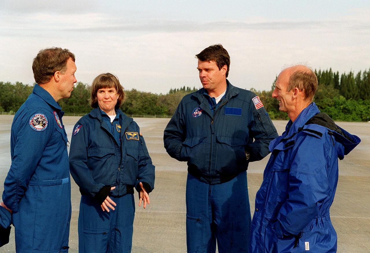
On the runway at the Shuttle Landing Facility, STS-99 crew members Pilot Dominic Gorie, Mission Specialist Janice Voss, Commander Kevin Kregel and Mission Specialist Gerhard Thiele discuss departure plans to Houston. Kregel and Gorie will be piloting T-38 jets with Voss and Thiele as passengers. During the Jan. 31 launch countdown, Endeavour's enhanced master events controller (E-MEC) No. 2 failed a standard preflight test. Launch was postponed and Shuttle managers decided to replace the E-MEC located in the orbiter's aft compartment. Launch controllers will be in a position to begin the STS-99 countdown the morning of Feb. 6 and ready to support a launch midto latenext week pending availability of the Eastern Range. The postponed launch gives the crew an opportunity for more training and time with their families. Known as the Shuttle Radar Topography Mission, it will chart a new course to produce unrivaled 3-D images of the Earth's surface, using two antennae and a 200-foot-long section of space station-derived mast protruding from the payload bay. The result could be close to 1 trillion measurements of the Earth's topography. Besides contributing to the production of better maps, these measurements could lead to improved water drainage modeling, more realistic flight simulators, better locations for cell phone towers, and enhanced navigation safety

On the runway at the Shuttle Landing Facility, STS-99 crew members Mission Specialists Gerhard Thiele and Janice Voss, Commander Kevin Kregel and Pilot Dominic Gorie briefly talk to the media about their imminent departure to Houston. Kregel and Gorie will be piloting T-38 jets with Voss and Thiele as passengers. During the Jan. 31 launch countdown, Endeavour's enhanced master events controller (E-MEC) No. 2 failed a standard preflight test. Launch was postponed and Shuttle managers decided to replace the E-MEC located in the orbiter's aft compartment. Launch controllers will be in a position to begin the STS-99 countdown the morning of Feb. 6 and ready to support a launch midto late next week pending availability of the Eastern Range. The postponed launch gives the crew an opportunity for more training and time with their families. Known as the Shuttle Radar Topography Mission, it will chart a new course to produce unrivaled 3-D images of the Earth's surface, using two antennae and a 200-foot-long section of space station-derived mast protruding from the payload bay. The result could be close to 1 trillion measurements of the Earth's topography. Besides contributing to the production of better maps, these measurements could lead to improved water drainage modeling, more realistic flight simulators, better locations for cell phone towers, and enhanced navigation safety
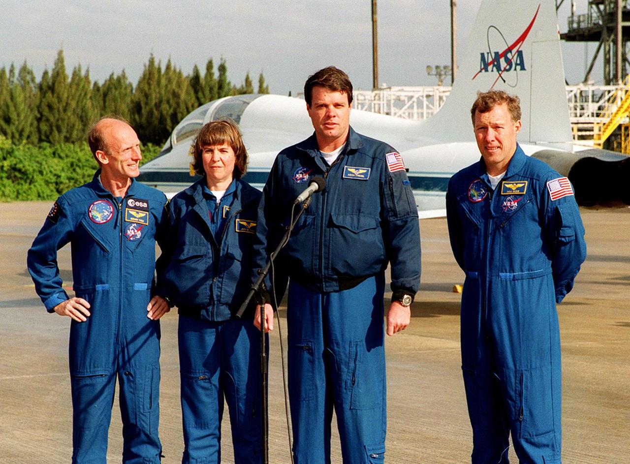
On the runway at the Shuttle Landing Facility, STS-99 crew members Mission Specialists Gerhard Thiele and Janice Voss, Commander Kevin Kregel and Pilot Dominic Gorie briefly talk to the media about their imminent departure to Houston. Kregel and Gorie will be piloting T-38 jets with Voss and Thiele as passengers. During the Jan. 31 launch countdown, Endeavour's enhanced master events controller (E-MEC) No. 2 failed a standard preflight test. Launch was postponed and Shuttle managers decided to replace the E-MEC located in the orbiter's aft compartment. Launch controllers will be in a position to begin the STS-99 countdown the morning of Feb. 6 and ready to support a launch midto late next week pending availability of the Eastern Range. The postponed launch gives the crew an opportunity for more training and time with their families. Known as the Shuttle Radar Topography Mission, it will chart a new course to produce unrivaled 3-D images of the Earth's surface, using two antennae and a 200-foot-long section of space station-derived mast protruding from the payload bay. The result could be close to 1 trillion measurements of the Earth's topography. Besides contributing to the production of better maps, these measurements could lead to improved water drainage modeling, more realistic flight simulators, better locations for cell phone towers, and enhanced navigation safety

STS-99 Mission Specialist Mamoru Mohri of Japan waves before his departure from Patrick Air Force Base and return to Houston. With the postponement of the launch of STS-99 on Jan. 31, the crew have an opportunity for more training and time with their families. During the launch countdown, Endeavour's enhanced master events controller (E-MEC) No. 2 failed a standard preflight test. Launch was postponed and Shuttle managers decided to replace the E-MEC located in the orbiter's aft compartment. Launch controllers will be in a position to begin the STS-99 countdown the morning of Feb. 6 and ready to support a launch midto late next week pending availability of the Eastern Range. Known as the Shuttle Radar Topography Mission, it will chart a new course to produce unrivaled 3-D images of the Earth's surface, using two antennae and a 200-foot-long section of space station-derived mast protruding from the payload bay. The result could be close to 1 trillion measurements of the Earth's topography. Besides contributing to the production of better maps, these measurements could lead to improved water drainage modeling, more realistic flight simulators, better locations for cell phone towers, and enhanced navigation safety