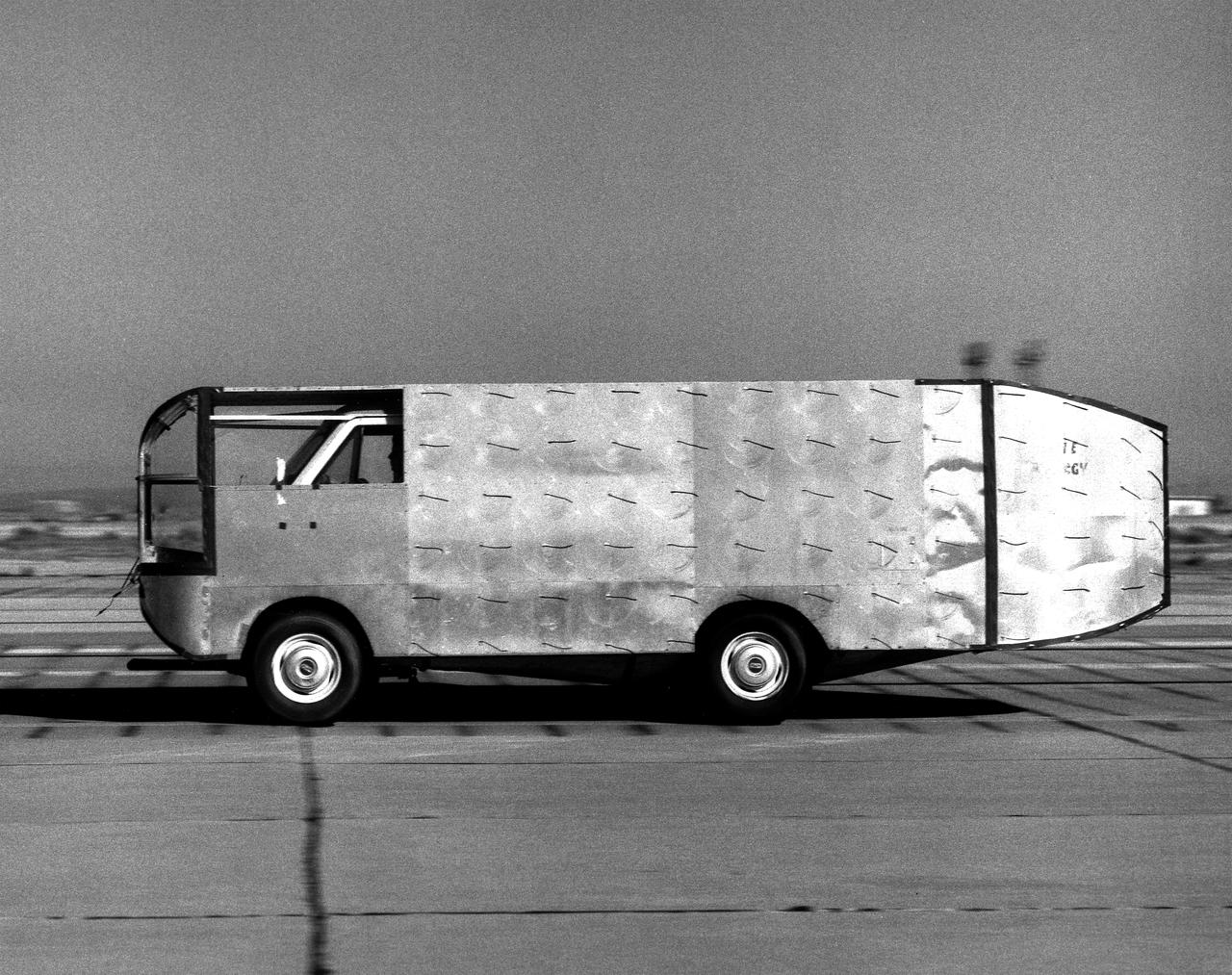
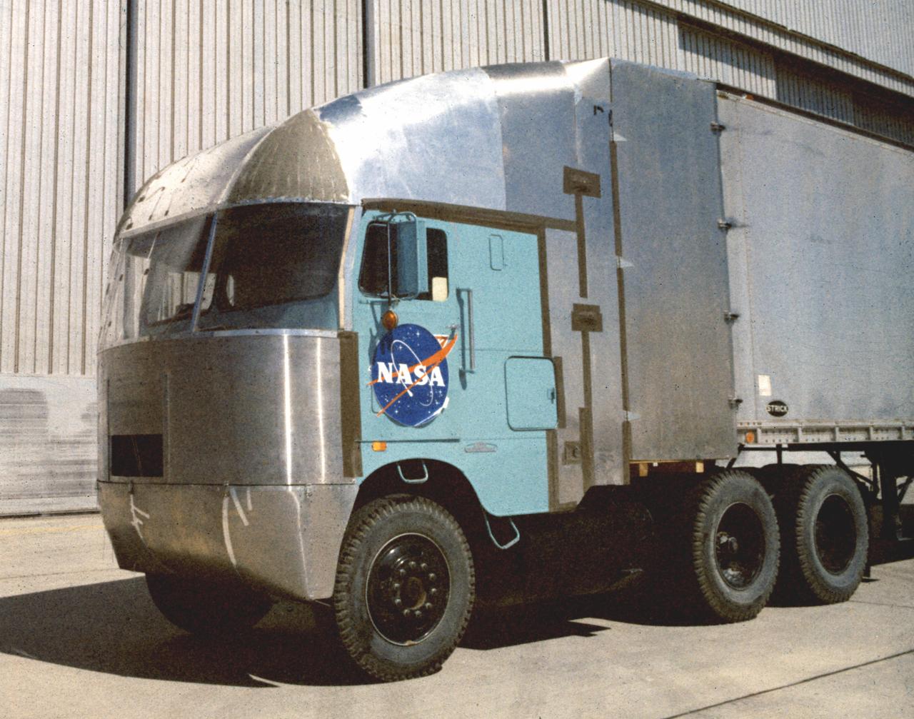
Air flow testing on aerodynamic truck
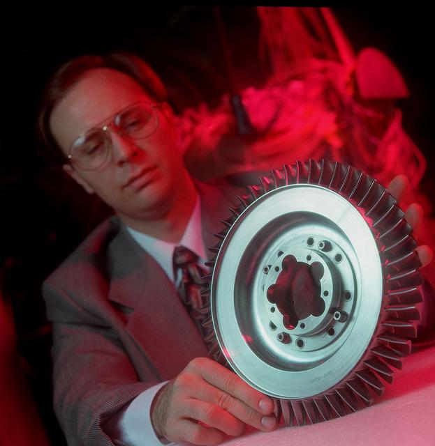
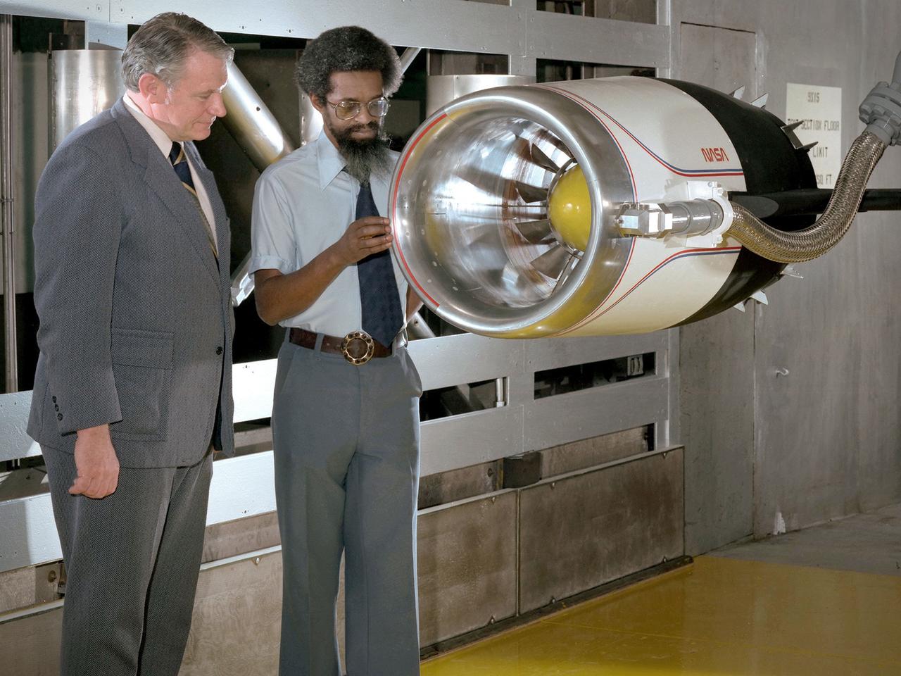
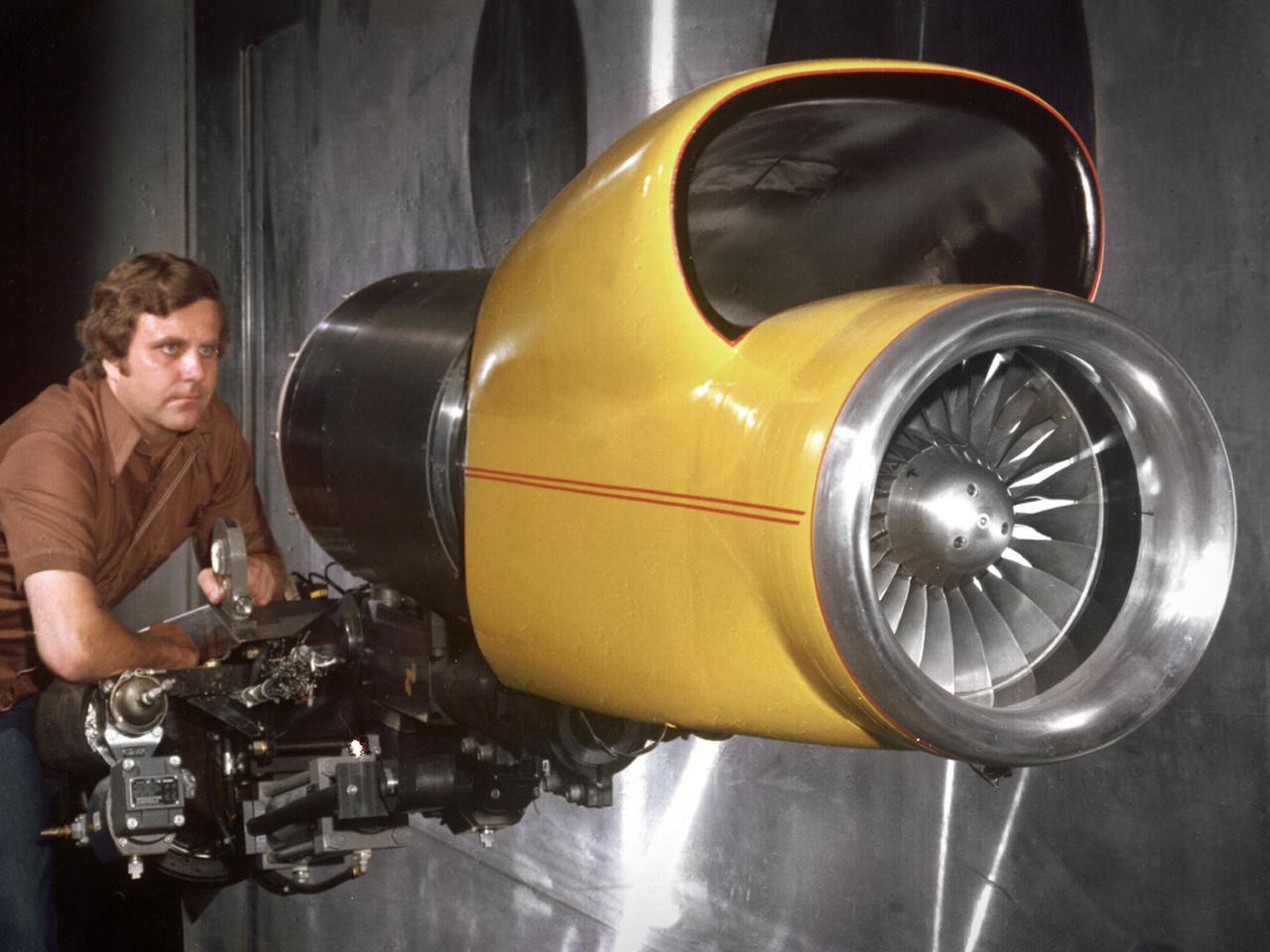
A NASA scientist displays Space Shuttle Main Engine (SSME) turbine component which underwent air flow tests at Marshall's Structures and Dynamics Lab. Such studies could improve efficiency of aircraft engines, and lower operational costs.
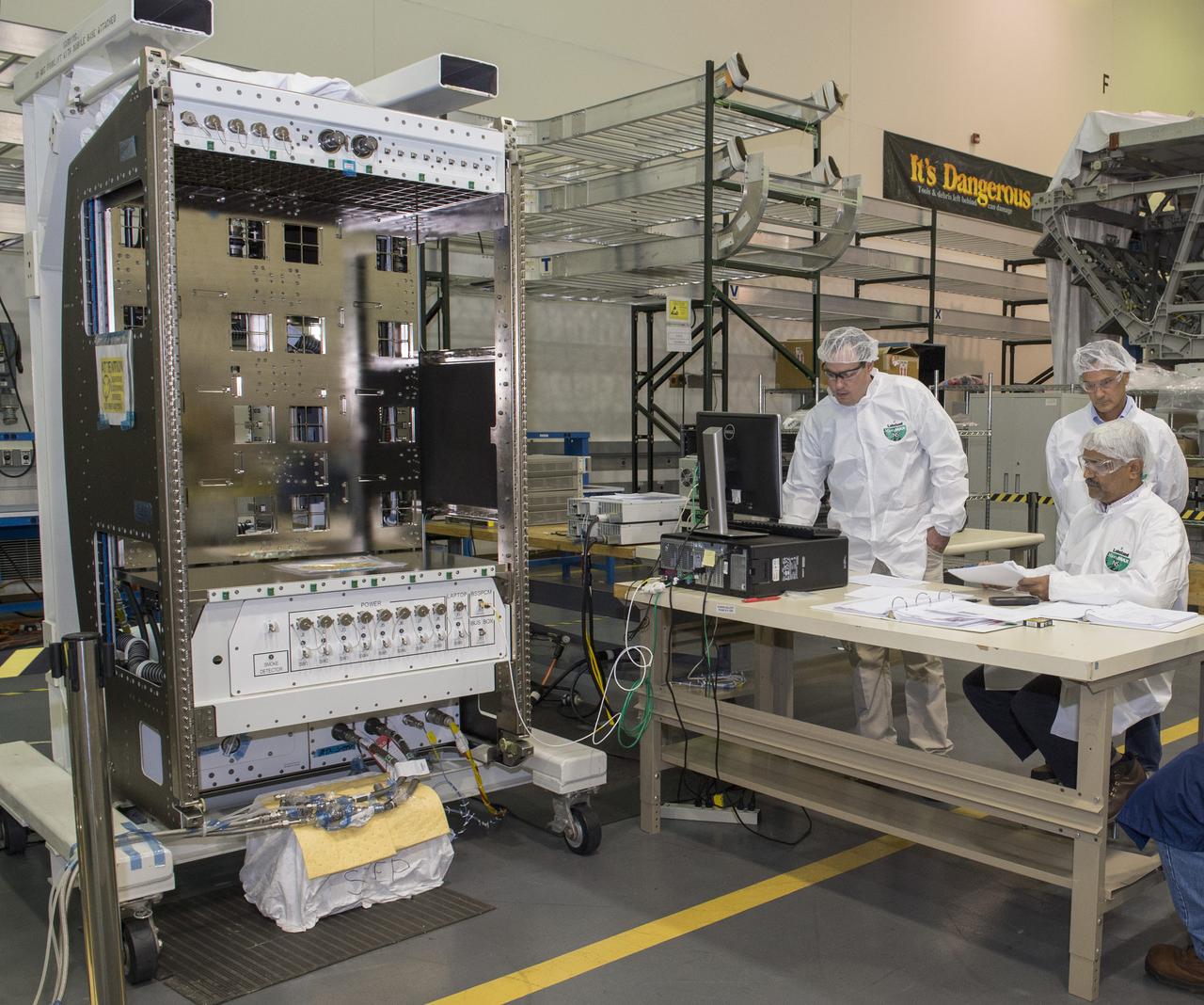
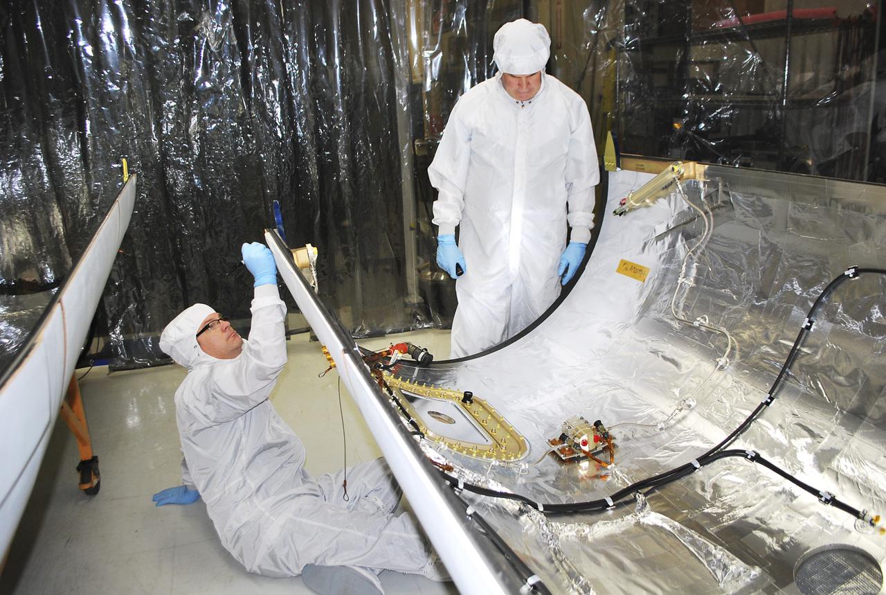
Boeing engineers, Chris Chapman, left, Greg Clark, center, and Ashesh Patel, right, perform air flow balance testing on NASA's new Basic Express Racks. The racks, developed at Marshall, will expand the capabilities for science research aboard the International Space Station. Delivery to the station is scheduled for late 2018.
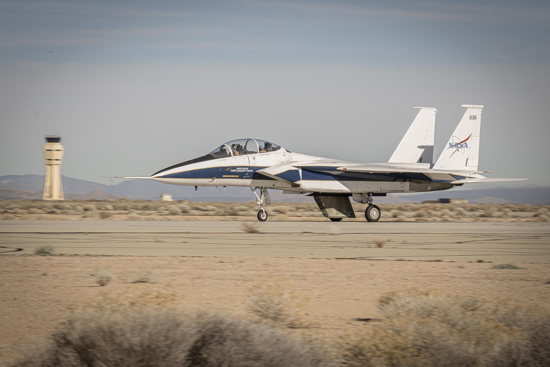
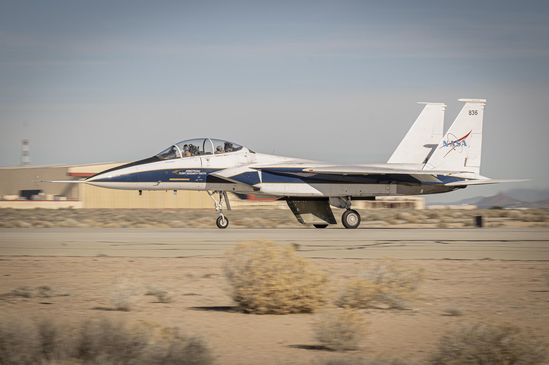
NASA’s Cross Flow Attenuated Natural Laminar Flow (CATNLF) scale model completes its first major milestone – high-speed taxi test – Tuesday, Jan. 12, 2026, at Edwards Air Force Base in California. NASA’s F-15 research aircraft, with the 3-foot-tall test article mounted on its underside, reached speeds of approximately 144 mph during testing. If successful, the technology could be applied to future commercial aircraft to improve efficiency and potentially reduce fuel consumption.
NASA’s Cross Flow Attenuated Natural Laminar Flow (CATNLF) scale model completes its first major milestone – high-speed taxi test – Tuesday, Jan. 12, 2026, at Edwards Air Force Base in California. NASA’s F-15 research aircraft, with the 3-foot-tall test article mounted on its underside, reached speeds of approximately 144 mph during testing. If successful, the technology could be applied to future commercial aircraft to improve efficiency and potentially reduce fuel consumption.
Air flow testing on aerodynamic truck
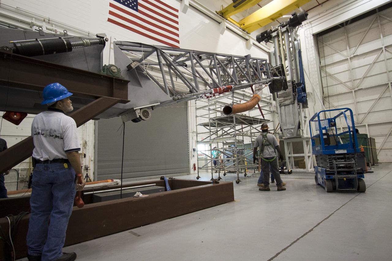
Return to Flight ( RTF ) flow line Air Test
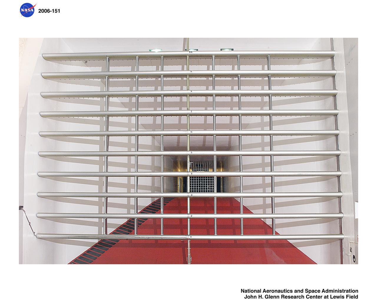
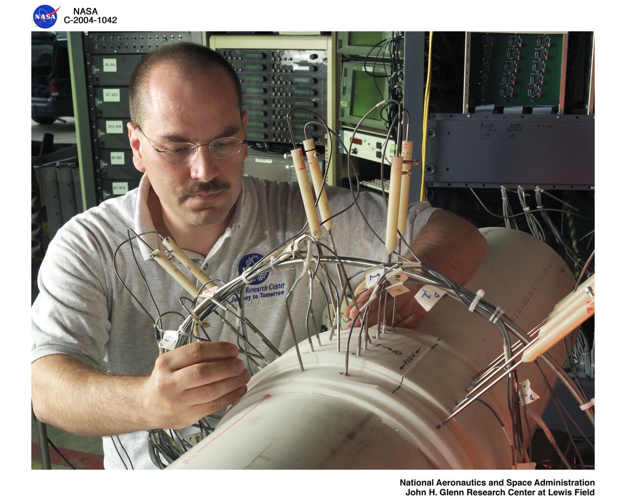
Spray Bars with new vertical fins to stabilize air flow. Test section is seen in background
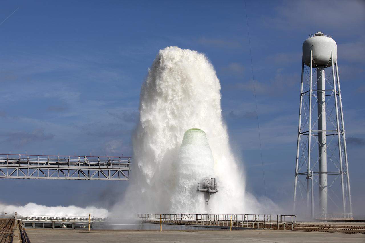
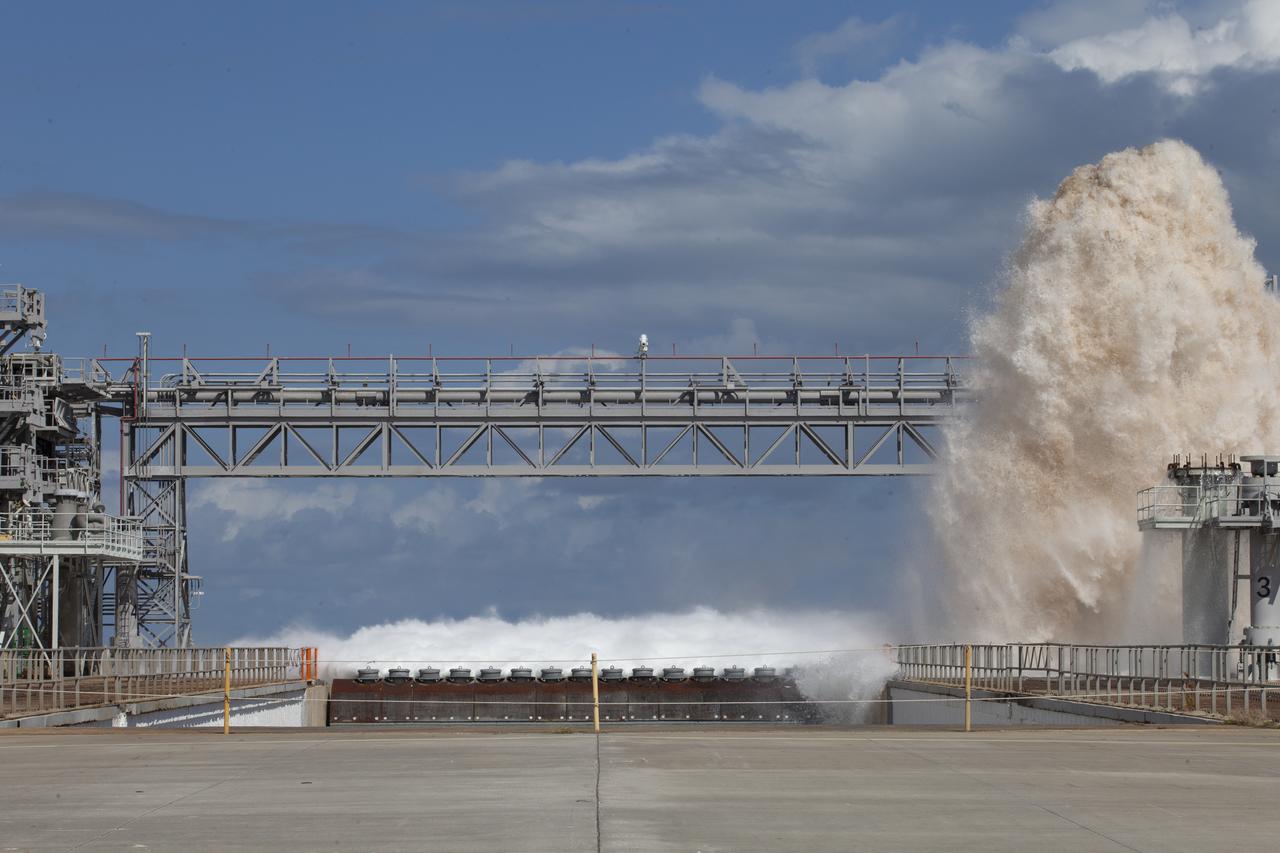
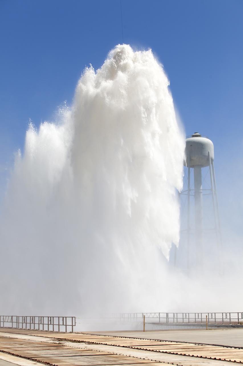
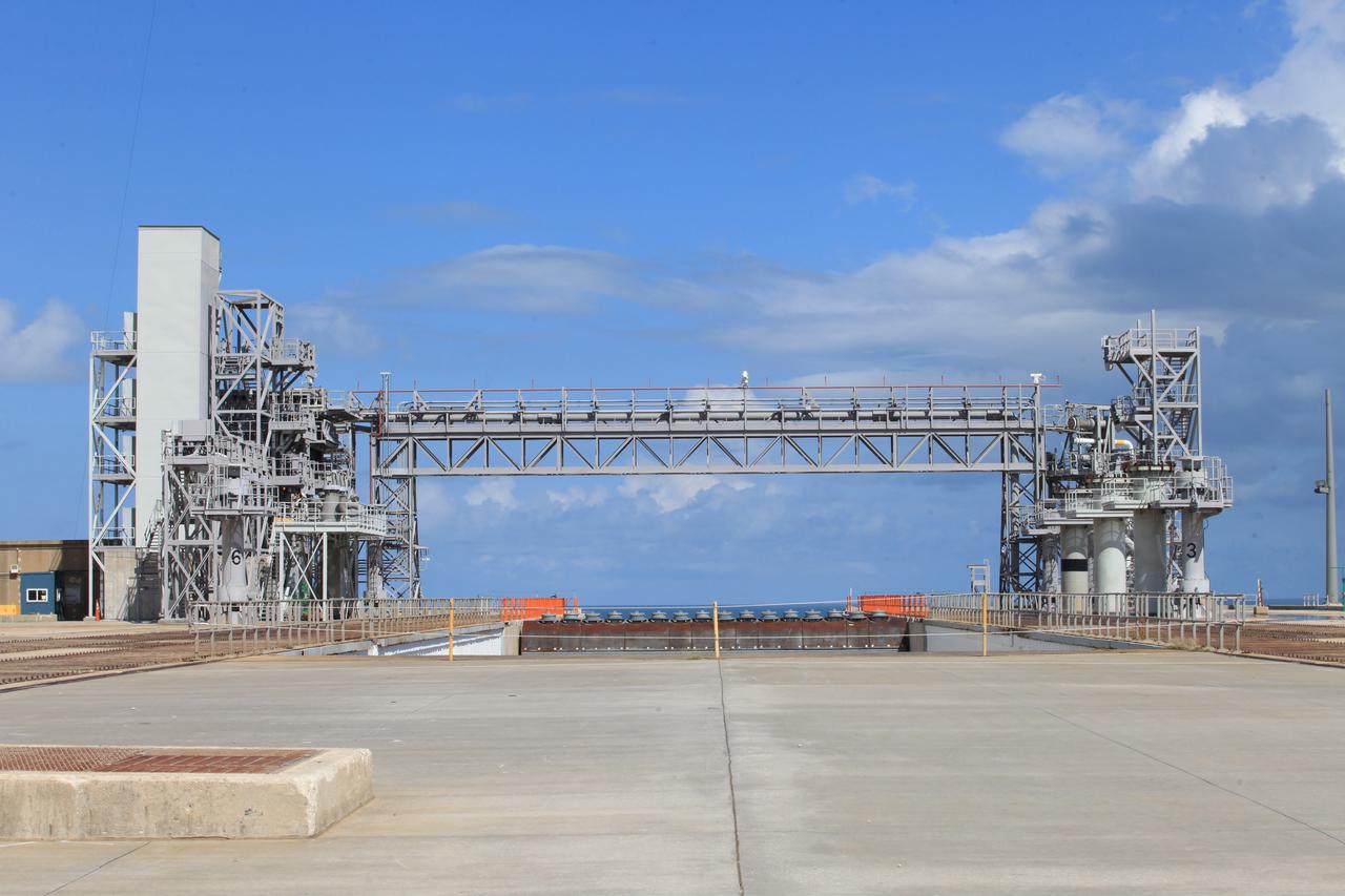
About 450,000 gallons of water flowed at high speed from a holding tank through new and modified piping and valves, the flame trench, flame deflector nozzles and mobile launcher interface risers during a wet flow test at Launch Pad 39B at NASA's Kennedy Space Center in Florida. At peak flow, the water reached about 100 feet in the air above the pad surface. The test was a milestone to confirm and baseline the performance of the Ignition Overpressure/Sound Suppression system. During launch of NASA's Space Launch System rocket and Orion spacecraft, the high-speed water flow will help protect the vehicle from the extreme acoustic and temperature environment during ignition and liftoff.

About 450,000 gallons of water flowed at high speed from a holding tank through new and modified piping and valves, the flame trench, flame deflector nozzles and mobile launcher interface risers during a wet flow test at Launch Pad 39B at NASA's Kennedy Space Center in Florida. At peak flow, the water reached about 100 feet in the air above the pad surface. The test was a milestone to confirm and baseline the performance of the Ignition Overpressure/Sound Suppression system. During launch of NASA's Space Launch System rocket and Orion spacecraft, the high-speed water flow will help protect the vehicle from the extreme acoustic and temperature environment during ignition and liftoff.
About 450,000 gallons of water flowed at high speed from a holding tank through new and modified piping and valves, the flame trench, flame deflector nozzles and mobile launcher interface risers during a wet flow test at Launch Pad 39B at NASA's Kennedy Space Center in Florida. At peak flow, the water reached about 100 feet in the air above the pad surface. The test was a milestone to confirm and baseline the performance of the Ignition Overpressure/Sound Suppression system. During launch of NASA's Space Launch System rocket and Orion spacecraft, the high-speed water flow will help protect the vehicle from the extreme acoustic and temperature environment during ignition and liftoff.

About 450,000 gallons of water flowed at high speed from a holding tank through new and modified piping and valves, the flame trench, flame deflector nozzles and mobile launcher interface risers during a wet flow test at Launch Pad 39B at NASA's Kennedy Space Center in Florida. At peak flow, the water reached about 100 feet in the air above the pad surface. The test was a milestone to confirm and baseline the performance of the Ignition Overpressure/Sound Suppression system. During launch of NASA's Space Launch System rocket and Orion spacecraft, the high-speed water flow will help protect the vehicle from the extreme acoustic and temperature environment during ignition and liftoff.
About 450,000 gallons of water flowed at high speed from a holding tank through new and modified piping and valves, the flame trench, flame deflector nozzles and mobile launcher interface risers during a wet flow test at Launch Pad 39B at NASA's Kennedy Space Center in Florida. At peak flow, the water reached about 100 feet in the air above the pad surface. The test was a milestone to confirm and baseline the performance of the Ignition Overpressure/Sound Suppression system. During launch of NASA's Space Launch System rocket and Orion spacecraft, the high-speed water flow will help protect the vehicle from the extreme acoustic and temperature environment during ignition and liftoff.
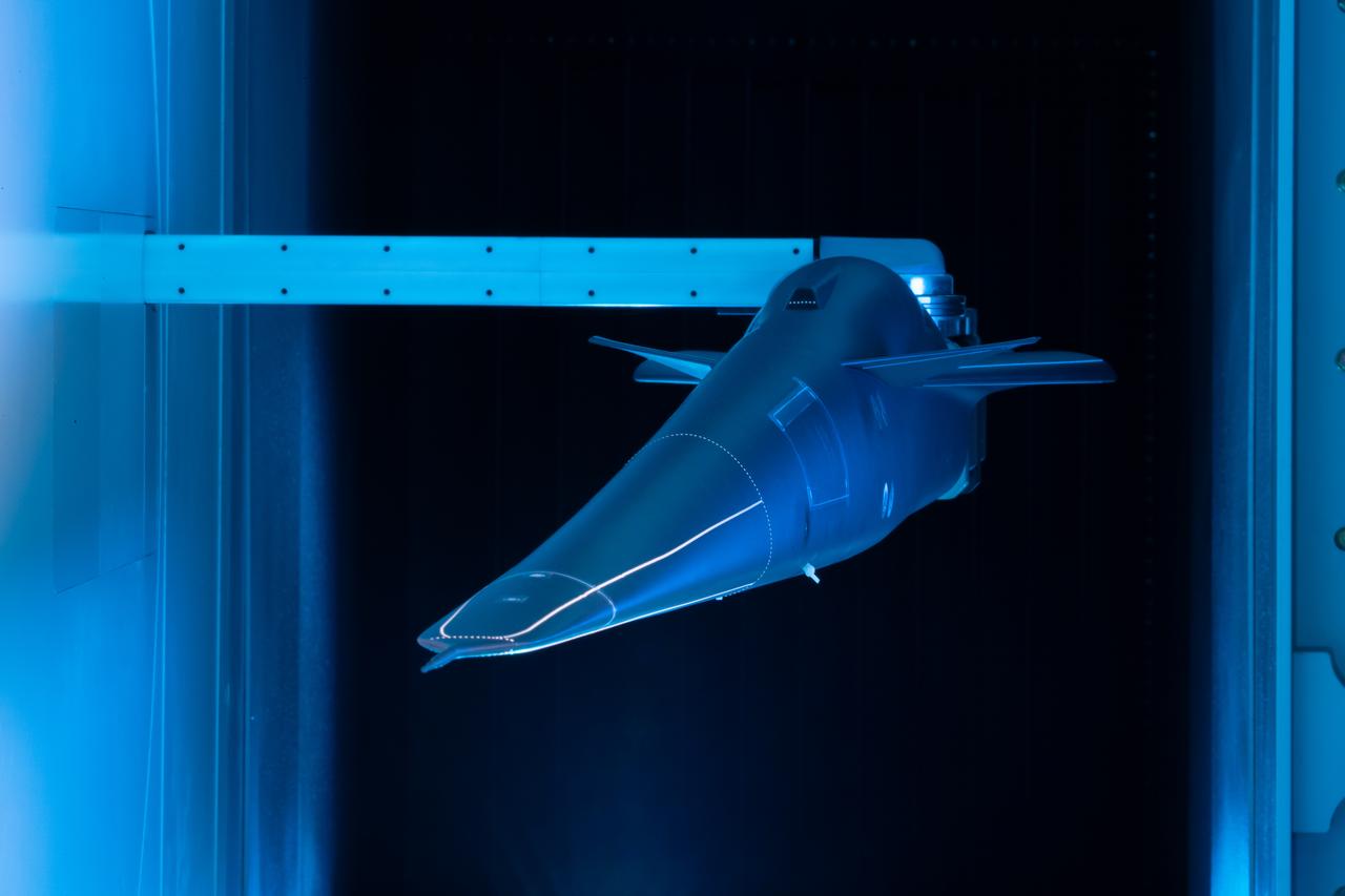
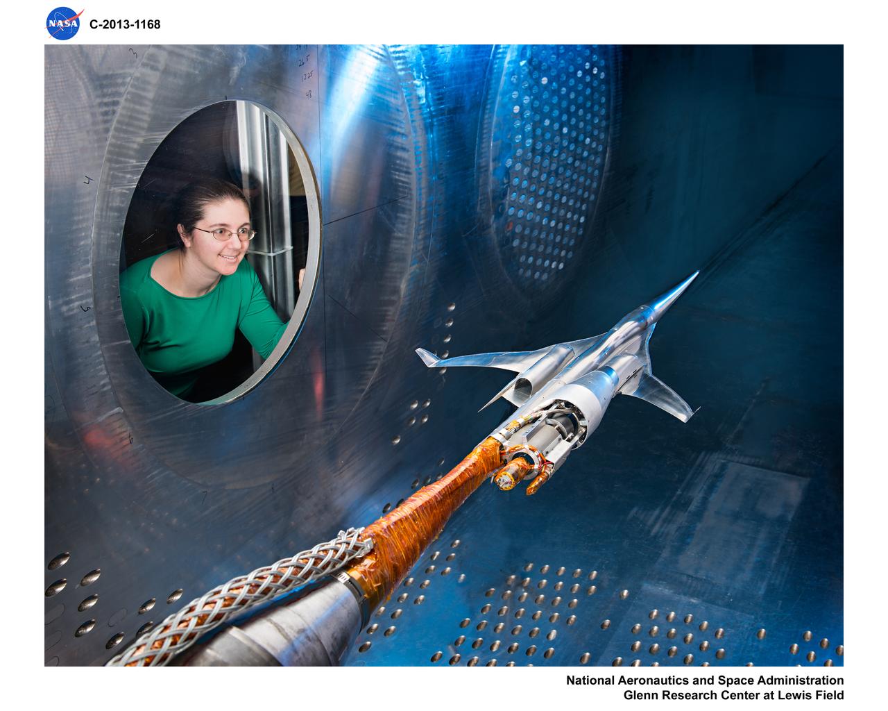
Event: Forebody and Nose - Windtunnel Testing A model of the X-59 forebody is shown in the Lockheed Martin Skunk Works’ wind tunnel in Palmdale, California. These tests gave the team measurements of wind flow angle around the aircraft’s nose and confirmed computer predictions made using computational fluid dynamics (CFD) software tools. The data will be fed into the aircraft flight control system to tell the pilot the aircraft’s altitude, speed and angle. This is part of NASA’s Quesst mission which plans to help enable supersonic air travel over land.
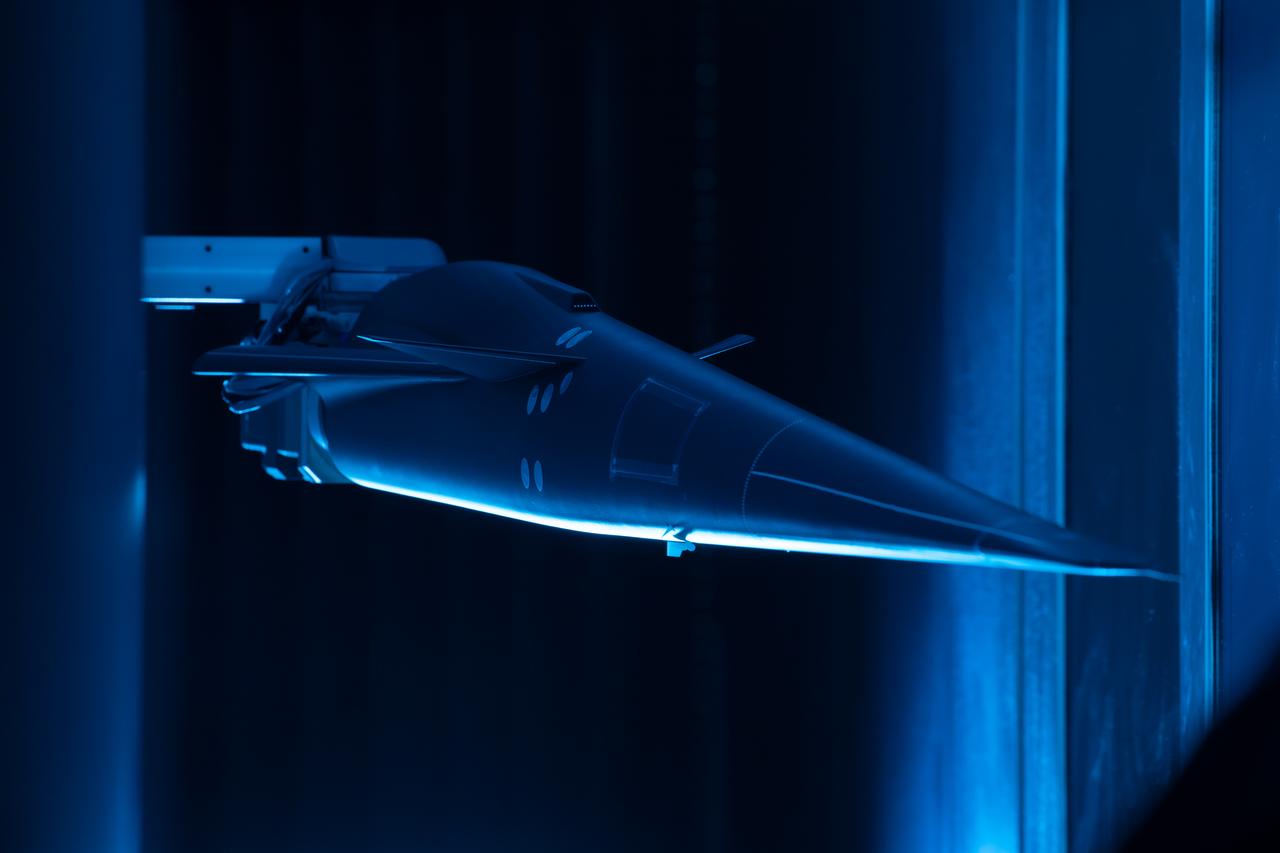
Event: Forebody and Nose - Windtunnel Testing A model of the X-59 forebody is shown in the Lockheed Martin Skunk Works’ wind tunnel in Palmdale, California. These tests gave the team measurements of wind flow angle around the aircraft’s nose and confirmed computer predictions made using computational fluid dynamics (CFD) software tools. The data will be fed into the aircraft flight control system to tell the pilot the aircraft’s altitude, speed and angle. This is part of NASA’s Quesst mission which plans to help enable supersonic air travel over land.

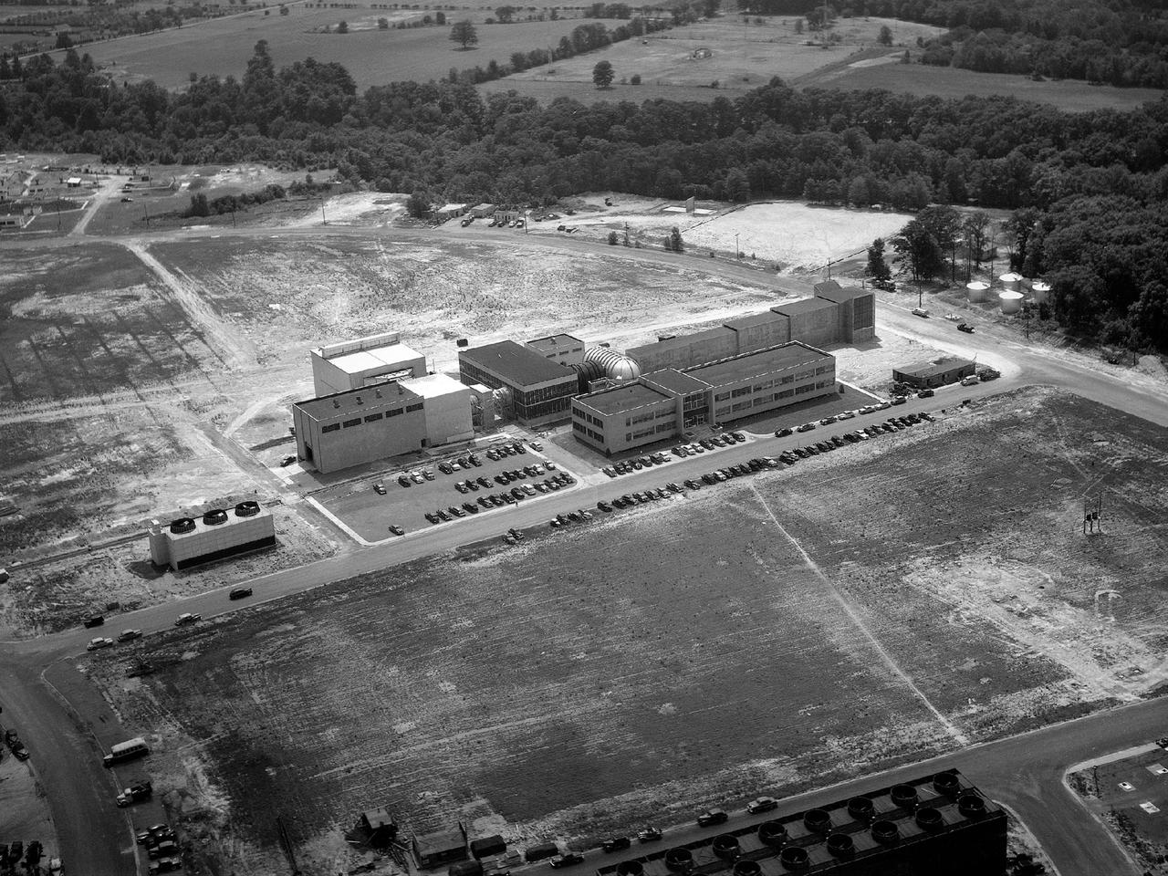
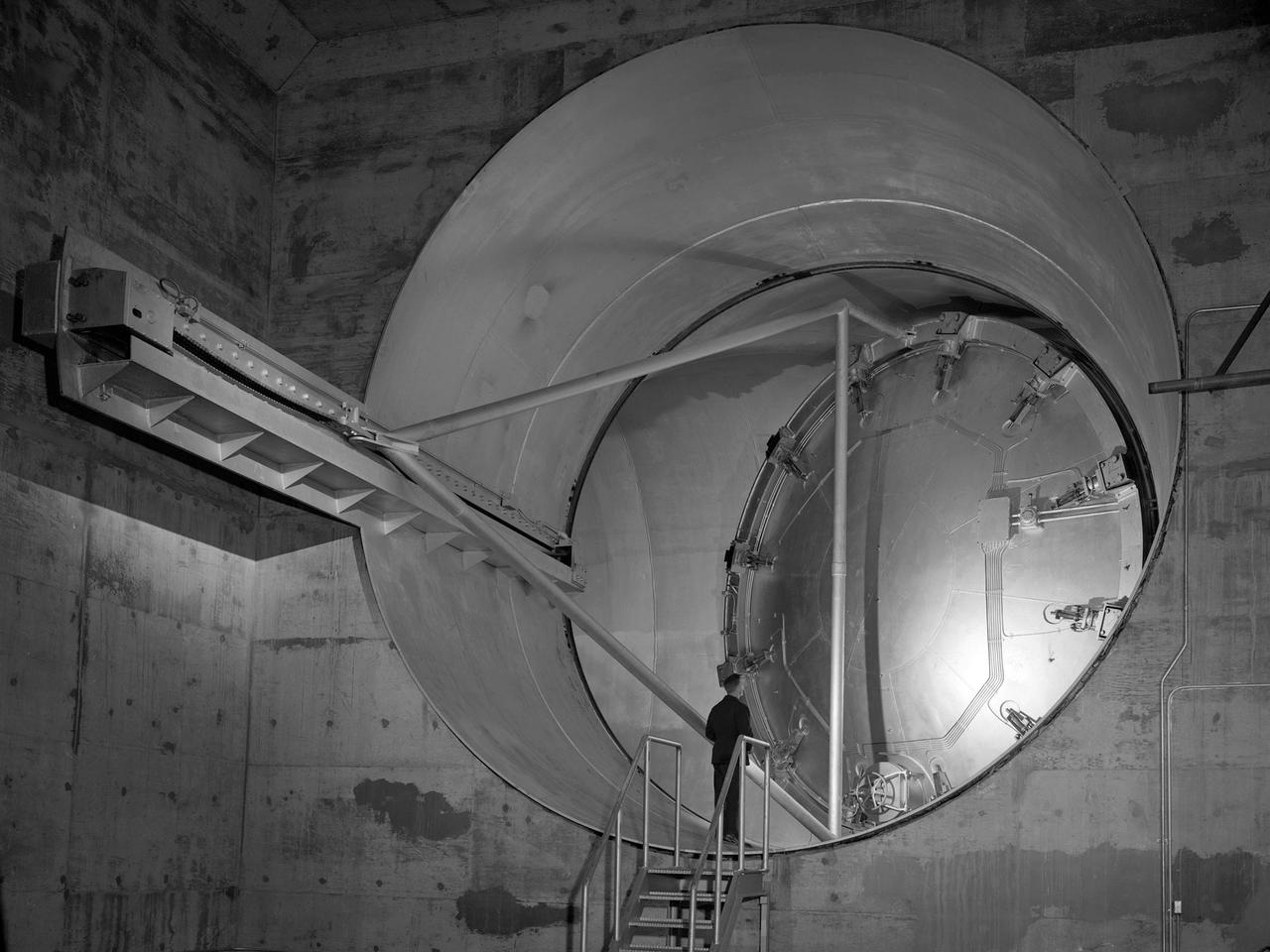
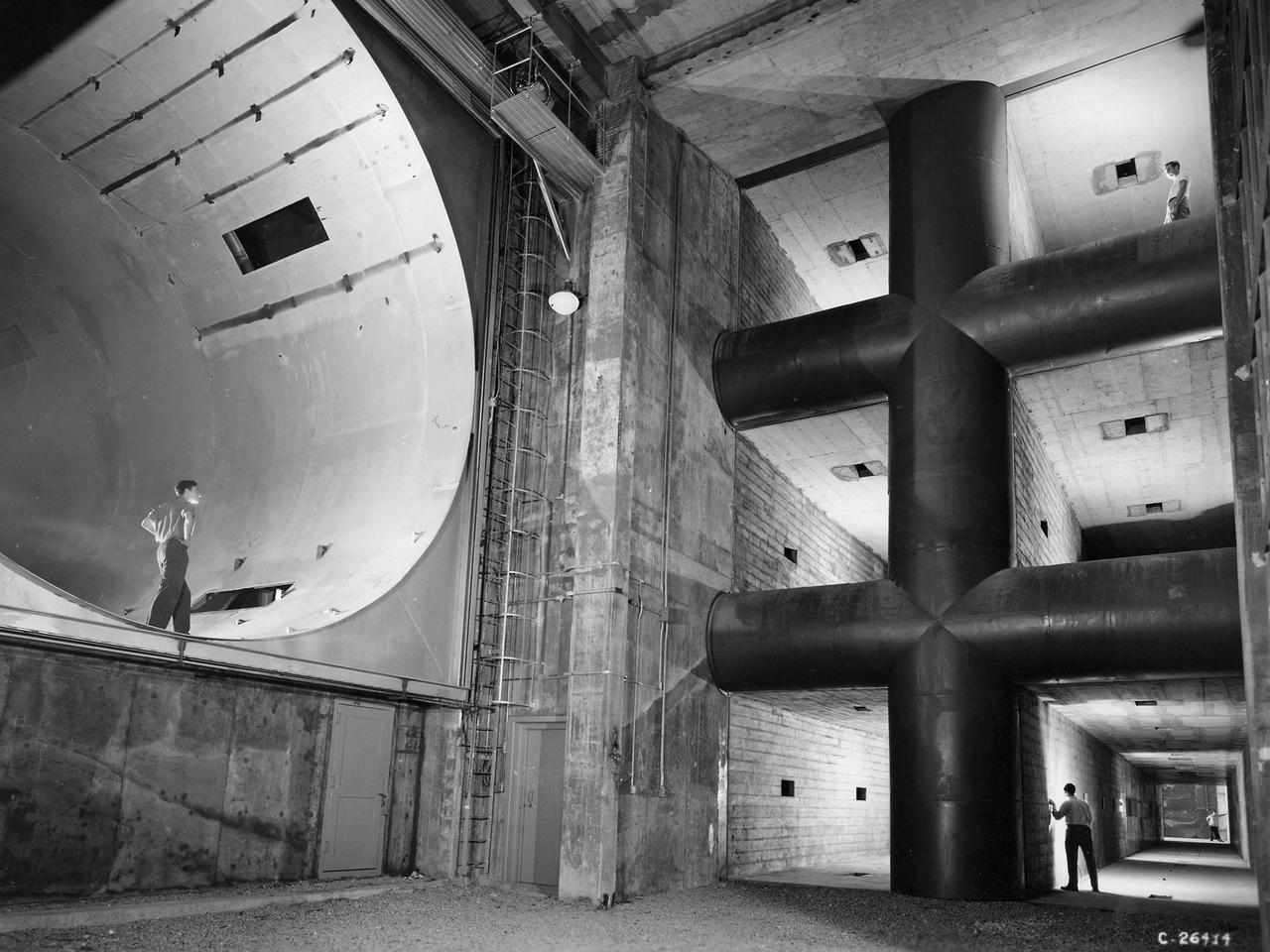
One of the two primary coolers at the Propulsion Systems Laboratory at the National Advisory Committee for Aeronautics (NACA) Lewis Flight Propulsion Laboratory. Engines could be run in simulated altitude conditions inside the facility’s two 14-foot-diameter and 24-foot-long test chambers. The Propulsion Systems Laboratory was the nation’s only facility that could run large full-size engine systems in controlled altitude conditions. At the time of this photograph, construction of the facility had recently been completed. Although not a wind tunnel, the Propulsion Systems Laboratory generated high-speed airflow through the interior of the engine. The air flow was pushed through the system by large compressors, adjusted by heating or refrigerating equipment, and de-moisturized by air dryers. The exhaust system served two roles: reducing the density of the air in the test chambers to simulate high altitudes and removing hot gases exhausted by the engines being tested. It was necessary to reduce the temperature of the extremely hot engine exhaust before the air reached the exhauster equipment. As the air flow exited through exhaust section of the test chamber, it entered into the giant primary cooler seen in this photograph. Narrow fins or vanes inside the cooler were filled with water. As the air flow passed between the vanes, its heat was transferred to the cooling water. The cooling water was cycled out of the system, carrying with it much of the exhaust heat.
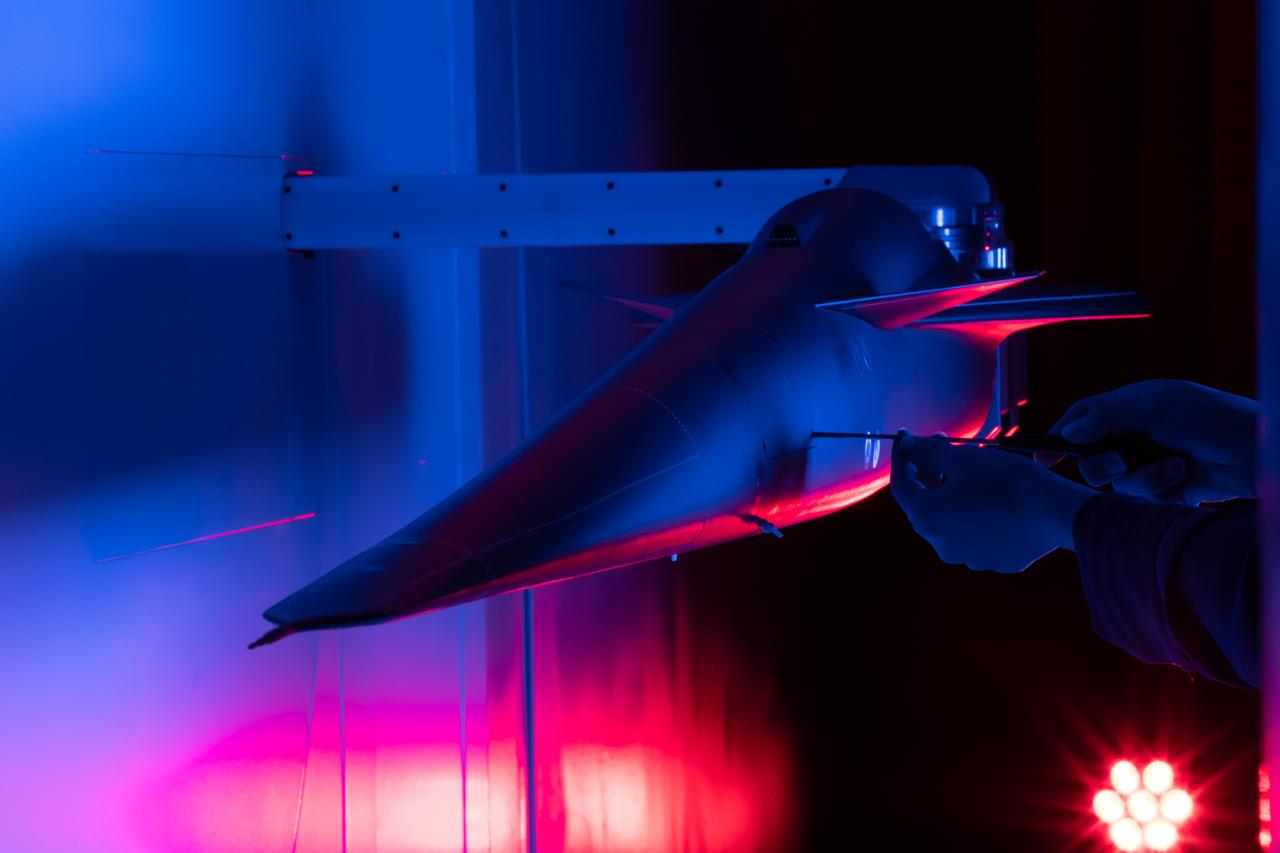
Event: Forebody and Nose - Windtunnel Testing A technician works on the X-59 model during testing in the low-speed wind tunnel at Lockheed Martin Skunk Works in Palmdale, California. These tests gave the team measurements of wind flow angle around the aircraft’s nose and confirmed computer predictions made using computational fluid dynamics (CFD) software tools. The data will be fed into the aircraft flight control system to tell the pilot the aircraft’s altitude, speed, and angle. This is part of NASA’s Quesst mission which plans to help enable supersonic air travel over land.
Center Director John McCarthy, left, and researcher Al Johns pose with a one-third scale model of a Grumman Aerospace tilt engine nacelle for Vertical and Short Takeoff and Landing (V/STOL) in the 9- by 15-Foot Low Speed Wind Tunnel at the National Aeronautics and Space Administration (NASA) Lewis Research Center. Lewis researchers had been studying tilt nacelle and inlet issues for several years. One area of concern was the inlet flow separation during the transition from horizontal to vertical flight. The separation of air flow from the inlet’s internal components could significantly stress the fan blades or cause a loss of thrust. In 1978 NASA researchers Robert Williams and Al Johns teamed with Grumman’s H.C. Potonides to develop a series of tests in the Lewis 9- by 15-foot tunnel to study a device designed to delay the flow separation by blowing additional air into the inlet. A jet of air, supplied through the hose on the right, was blown over the inlet surfaces. The researchers verified that the air jet slowed the flow separation. They found that the blowing on boundary layer control resulted in a doubling of the angle-of-attack and decreases in compressor blade stresses and fan distortion. The tests were the first time the concept of blowing air for boundary layer control was demonstrated. Boundary layer control devices like this could result in smaller and lighter V/STOL inlets.

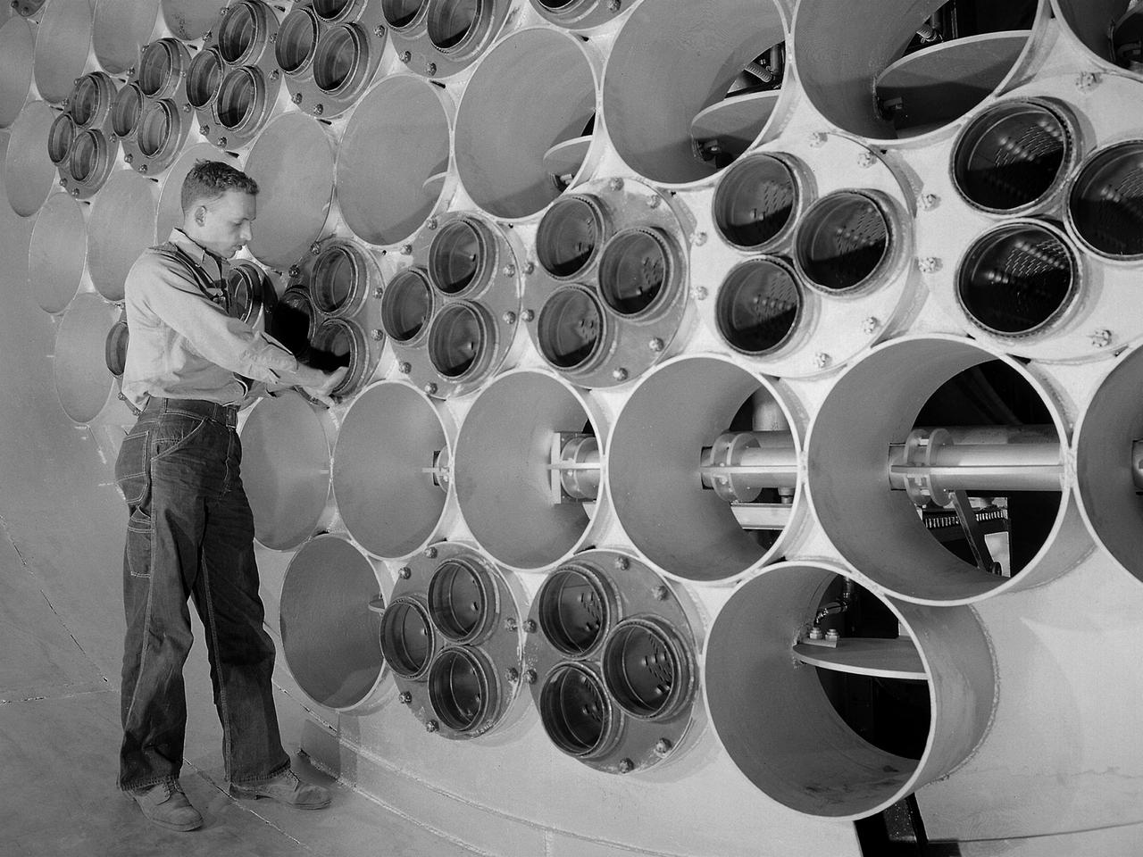
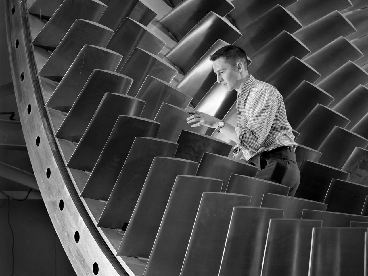
A technician at the National Advisory Committee for Aeronautics (NACA) Lewis Flight Propulsion Laboratory examines one of the massive axial-flow compressor stages that created the high-speed air flow through the 8- by 6-Foot Supersonic Wind Tunnel. The tunnel’s first run was on April 3, 1949, just over a week before this photograph was taken. The 8- by 6 was the laboratory’s first large supersonic wind tunnel and the NACA’s largest supersonic tunnel at the time. The 8- by 6-foot tunnel was originally an open-throat non-return tunnel. The supersonic air flow was blown through the tubular facility and expelled out the other end into the atmosphere with a roar. Complaints from the local community led to the addition of a muffler at the tunnel exit in 1956 and the eventual addition of a return leg. The return leg allowed the tunnel to be operated as either an open system with large doors venting directly to the atmosphere for propulsion system tests or as a closed loop for aerodynamic tests. The air flow was generated by a large seven-stage axial-flow compressor, seen in this photograph, that was powered by three electric motors with a combined 87,000 horsepower. The system required 36,000 kilowatts of power per hour to generate wind velocities of Mach 1.5, and 72,000 kilowatts per hour for Mach 2.0.

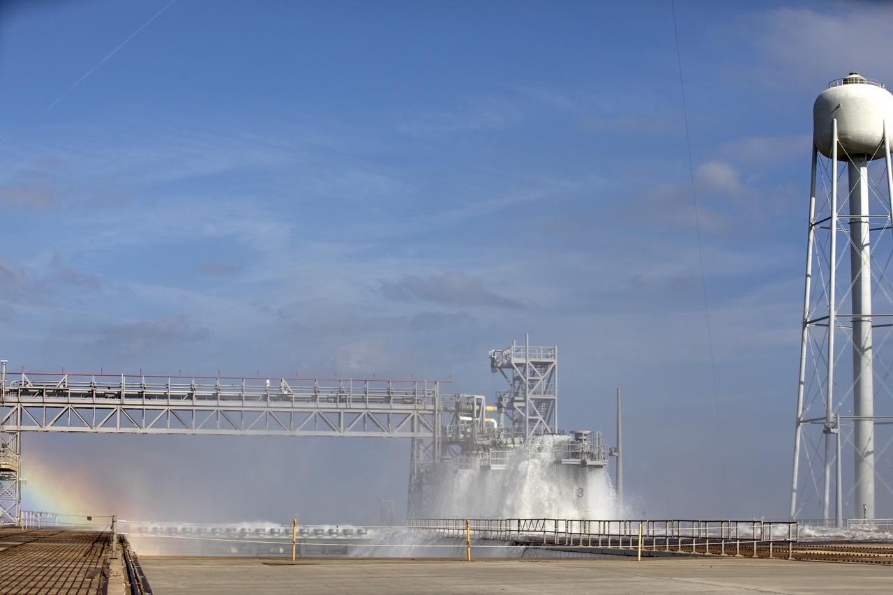
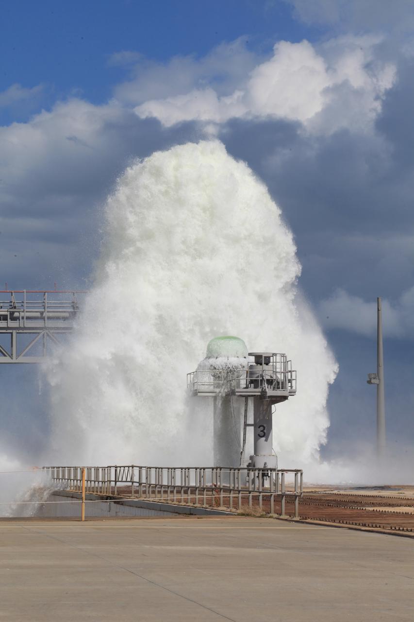
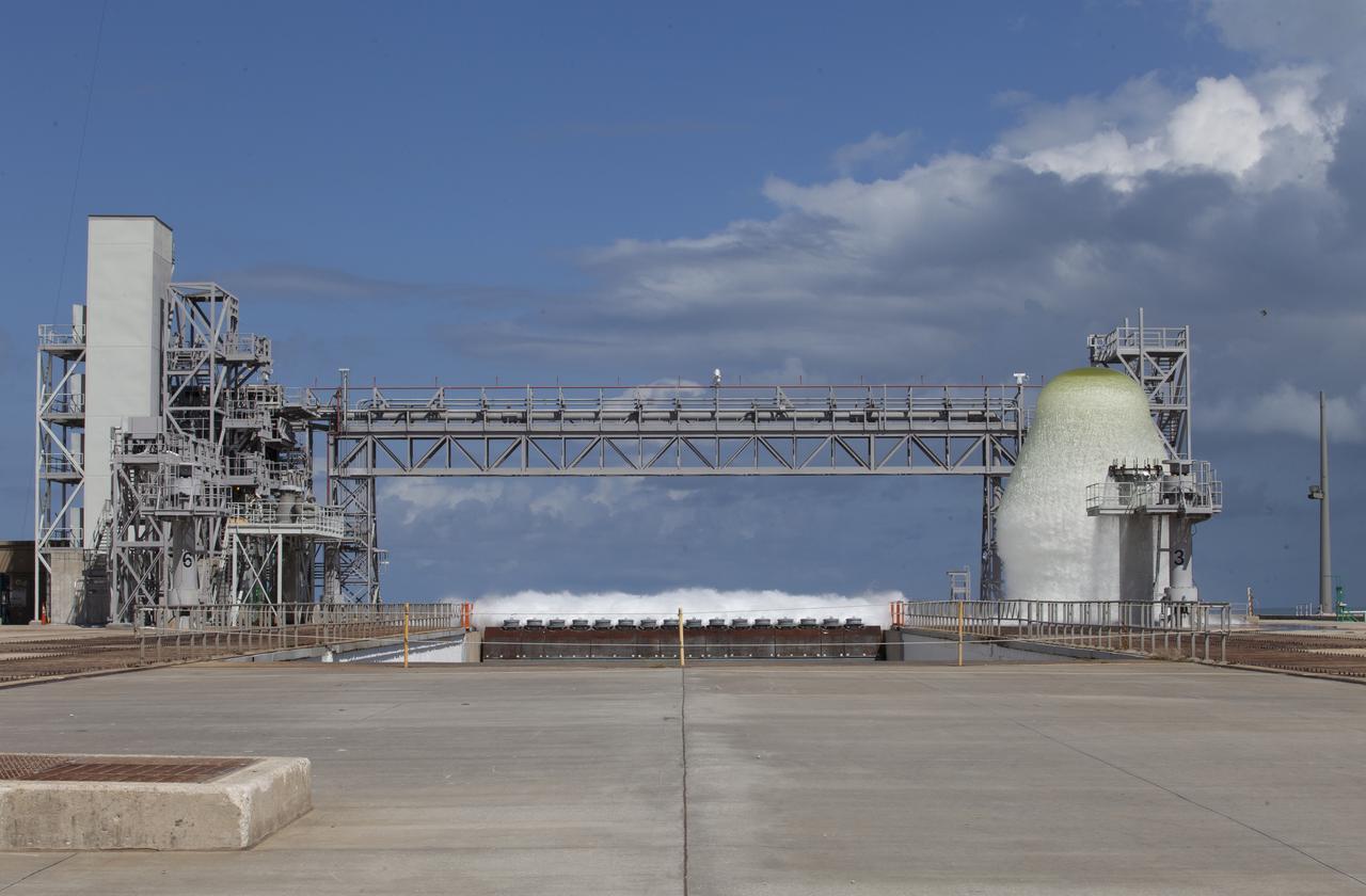
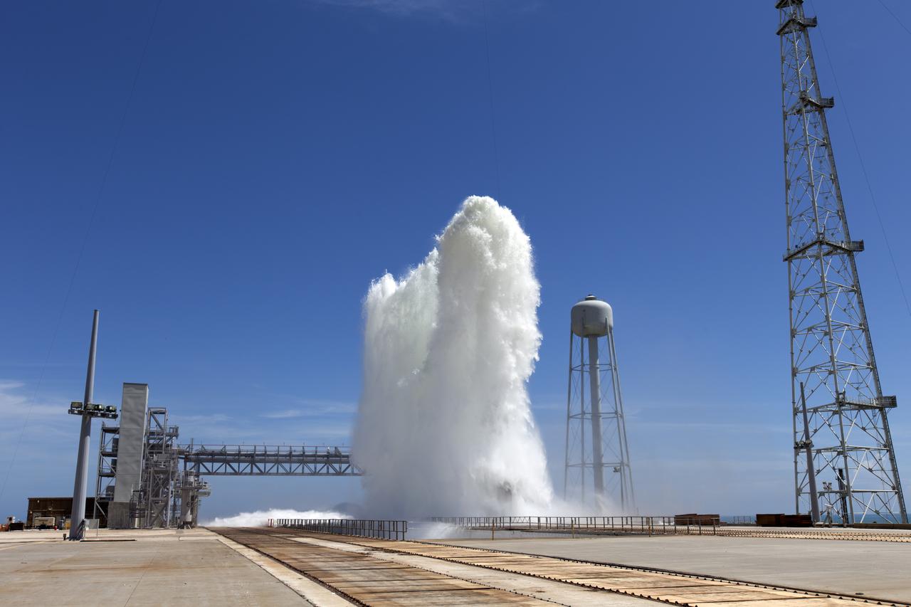
A flow test of the Ignition Overpressure Protection and Sound Suppression water deluge system is in progress at Launch Pad 39B at NASA's Kennedy Space Center in Florida, on Oct. 15, 2018. At peak flow, the water reaches about 100 feet in the air above the pad surface. It flows at high speed from a holding tank through new and modified piping and valves, the flame trench, flame deflector nozzles and mobile launcher interface risers. The testing is part of Exploration Ground System's preparation for the new Space Launch System rocket. Modifications were made to the pad after a previous wet flow test, increasing the performance of the system. During the launch of Exploration Mission-1 and subsequent missions, this water deluge system will release about 450,000 gallons of water across the mobile launcher and Flame Deflector to reduce the extreme heat and energy generated by the rocket during ignition and liftoff.

A flow test of the Ignition Overpressure Protection and Sound Suppression water deluge system is in progress at Launch Pad 39B at NASA's Kennedy Space Center in Florida, on Oct. 15, 2018. At peak flow, the water reaches about 100 feet in the air above the pad surface. It flows at high speed from a holding tank through new and modified piping and valves, the flame trench, flame deflector nozzles and mobile launcher interface risers. The testing is part of Exploration Ground System's preparation for the new Space Launch System rocket. Modifications were made to the pad after a previous wet flow test, increasing the performance of the system. During the launch of Exploration Mission-1 and subsequent missions, this water deluge system will release about 450,000 gallons of water across the mobile launcher and Flame Deflector to reduce the extreme heat and energy generated by the rocket during ignition and liftoff.
A flow test of the Ignition Overpressure Protection and Sound Suppression water deluge system is in progress at Launch Pad 39B at NASA's Kennedy Space Center in Florida, on Oct. 15, 2018. At peak flow, the water reaches about 100 feet in the air above the pad surface. It flows at high speed from a holding tank through new and modified piping and valves, the flame trench, flame deflector nozzles and mobile launcher interface risers. The testing is part of Exploration Ground System's preparation for the new Space Launch System rocket. Modifications were made to the pad after a previous wet flow test, increasing the performance of the system. During the launch of Exploration Mission-1 and subsequent missions, this water deluge system will release about 450,000 gallons of water across the mobile launcher and Flame Deflector to reduce the extreme heat and energy generated by the rocket during ignition and liftoff.

A flow test of the Ignition Overpressure Protection and Sound Suppression water deluge system is in progress at Launch Pad 39B at NASA's Kennedy Space Center in Florida, on Oct. 15, 2018. At peak flow, the water reaches about 100 feet in the air above the pad surface. It flows at high speed from a holding tank through new and modified piping and valves, the flame trench, flame deflector nozzles and mobile launcher interface risers. The testing is part of Exploration Ground System's preparation for the new Space Launch System rocket. Modifications were made to the pad after a previous wet flow test, increasing the performance of the system. During the launch of Exploration Mission-1 and subsequent missions, this water deluge system will release about 450,000 gallons of water across the mobile launcher and Flame Deflector to reduce the extreme heat and energy generated by the rocket during ignition and liftoff.
A flow test of the Ignition Overpressure Protection and Sound Suppression water deluge system is in progress at Launch Pad 39B at NASA's Kennedy Space Center in Florida, on Oct. 15, 2018. At peak flow, the water reaches about 100 feet in the air above the pad surface. It flows at high speed from a holding tank through new and modified piping and valves, the flame trench, flame deflector nozzles and mobile launcher interface risers. The testing is part of Exploration Ground System's preparation for the new Space Launch System rocket. Modifications were made to the pad after a previous wet flow test, increasing the performance of the system. During the launch of Exploration Mission-1 and subsequent missions, this water deluge system will release about 450,000 gallons of water across the mobile launcher and Flame Deflector to reduce the extreme heat and energy generated by the rocket during ignition and liftoff.
A flow test of the Ignition Overpressure Protection and Sound Suppression water deluge system is in progress at Launch Pad 39B at NASA's Kennedy Space Center in Florida, on Oct. 15, 2018. At peak flow, the water will reach about 100 feet in the air above the pad surface. It will flow at high speed from a holding tank through new and modified piping and valves, the flame trench, flame deflector nozzles and mobile launcher interface risers. The testing is part of Exploration Ground System's preparation for the new Space Launch System rocket. Modifications were made to the pad after a previous wet flow test, increasing the performance of the system. During the launch of Exploration Mission-1 and subsequent missions, this water deluge system will release about 450,000 gallons of water across the mobile launcher and Flame Deflector to reduce the extreme heat and energy generated by the rocket during ignition and liftoff.

A flow test of the Ignition Overpressure Protection and Sound Suppression water deluge system is in progress at Launch Pad 39B at NASA's Kennedy Space Center in Florida, on Oct. 15, 2018. At peak flow, the water reaches about 100 feet in the air above the pad surface. It flows at high speed from a holding tank through new and modified piping and valves, the flame trench, flame deflector nozzles and mobile launcher interface risers. The testing is part of Exploration Ground System's preparation for the new Space Launch System rocket. Modifications were made to the pad after a previous wet flow test, increasing the performance of the system. During the launch of Exploration Mission-1 and subsequent missions, this water deluge system will release about 450,000 gallons of water across the mobile launcher and Flame Deflector to reduce the extreme heat and energy generated by the rocket during ignition and liftoff.
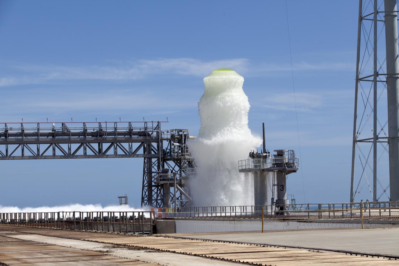
A flow test of the Ignition Overpressure Protection and Sound Suppression water deluge system begins at Launch Pad 39B at NASA's Kennedy Space Center in Florida, on Oct. 15, 2018. At peak flow, the water will reach about 100 feet in the air above the pad surface. It will flow at high speed from a holding tank through new and modified piping and valves, the flame trench, flame deflector nozzles and mobile launcher interface risers. The testing is part of Exploration Ground System's preparation for the new Space Launch System rocket. Modifications were made to the pad after a previous wet flow test, increasing the performance of the system. During the launch of Exploration Mission-1 and subsequent missions, this water deluge system will release about 450,000 gallons of water across the mobile launcher and Flame Deflector to reduce the extreme heat and energy generated by the rocket during ignition and liftoff.
Aerial view of the 8- by 6-Foot Supersonic Wind Tunnel in its original configuration at the National Advisory Committee for Aeronautics (NACA) Lewis Flight Propulsion Laboratory. The 8- by 6 was the laboratory’s first large supersonic wind tunnel. It was also the NACA’s most powerful supersonic tunnel, and its first facility capable of running an engine at supersonic speeds. The 8- by 6-foot tunnel has been used to study inlets and exit nozzles, fuel injectors, flameholders, exit nozzles, and controls on ramjet and turbojet propulsion systems. The 8- by 6 was originally an open-throat and non-return tunnel. This meant that the supersonic air flow was blown through the test section and out the other end into the atmosphere. In this photograph, the three drive motors in the structure at the left supplied power to the seven-stage axial-flow compressor in the light-colored structure. The air flow passed through flexible walls which were bent to create the desired speed. The test article was located in the 8- by 6-foot stainless steel test section located inside the steel pressure chamber at the center of this photograph. The tunnel dimensions were then gradually increased to slow the air flow before it exited into the atmosphere. The large two-story building in front of the tunnel was used as office space for the researchers.
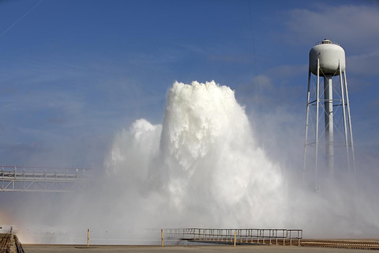
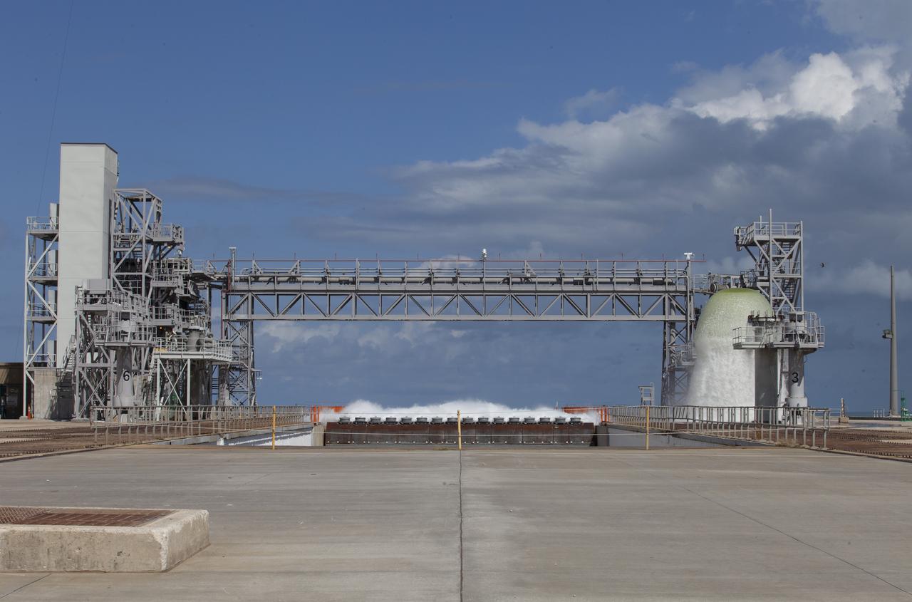
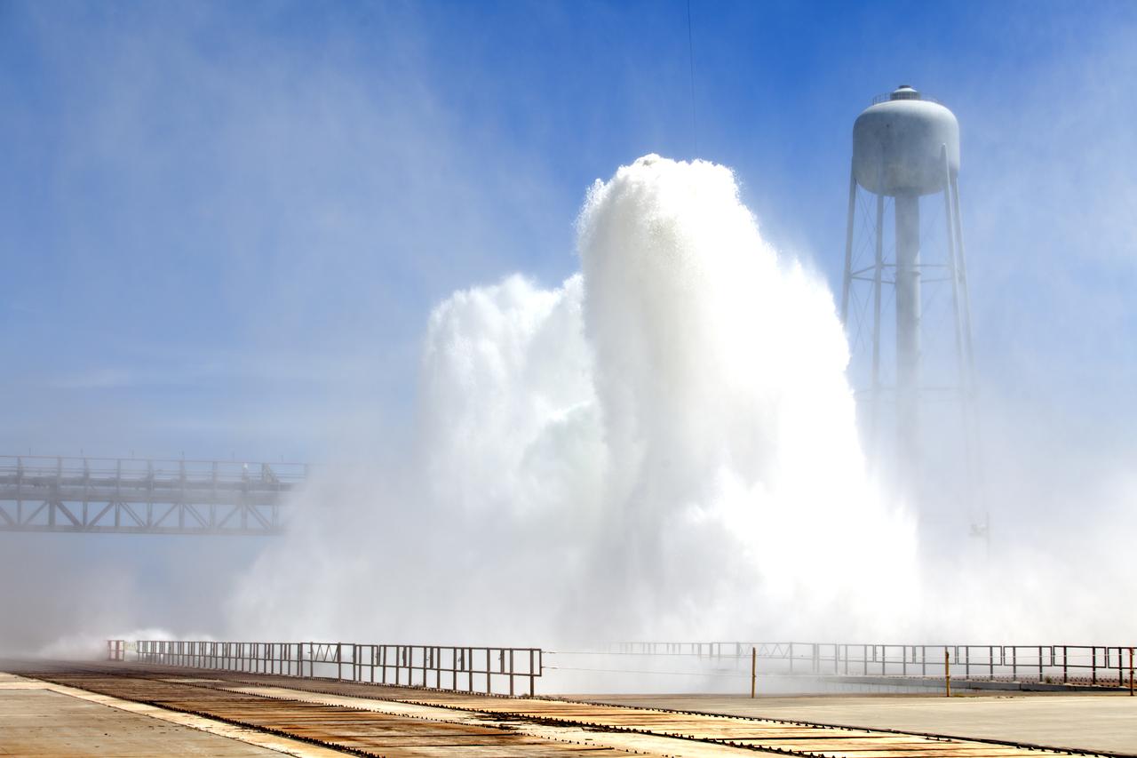
About 450,000 gallons of water flow at high speed from a holding tank through new and modified piping and valves, the flame trench, flame deflector nozzles and mobile launcher interface risers during a wet flow test on May 24, 2018, at Launch Pad 39B at NASA's Kennedy Space Center in Florida. At peak flow, the water reached about 100 feet in the air above the pad surface. The test was performed by Exploration Ground Systems to confirm the performance of the Ignition Overpressure/Sound Suppression system. During launch of NASA's Space Launch System rocket and Orion spacecraft, the high-speed water flow will help protect the vehicle from the extreme acoustic and temperature environment during ignition and liftoff.

About 450,000 gallons of water flow at high speed from a holding tank through new and modified piping and valves, the flame trench, flame deflector nozzles and mobile launcher interface risers during a wet flow test on May 24, 2018, at Launch Pad 39B at NASA's Kennedy Space Center in Florida. At peak flow, the water reached about 100 feet in the air above the pad surface. The test was performed by Exploration Ground Systems to confirm the performance of the Ignition Overpressure/Sound Suppression system. During launch of NASA's Space Launch System rocket and Orion spacecraft, the high-speed water flow will help protect the vehicle from the extreme acoustic and temperature environment during ignition and liftoff.
About 450,000 gallons of water flow at high speed from a holding tank through new and modified piping and valves, the flame trench, flame deflector nozzles and mobile launcher interface risers during a wet flow test on May 24, 2018, at Launch Pad 39B at NASA's Kennedy Space Center in Florida. At peak flow, the water reached about 100 feet in the air above the pad surface. The test was performed by Exploration Ground Systems to confirm the performance of the Ignition Overpressure/Sound Suppression system. During launch of NASA's Space Launch System rocket and Orion spacecraft, the high-speed water flow will help protect the vehicle from the extreme acoustic and temperature environment during ignition and liftoff.
About 450,000 gallons of water flow at high speed from a holding tank through new and modified piping and valves, the flame trench, flame deflector nozzles and mobile launcher interface risers during a wet flow test on May 24, 2018, at Launch Pad 39B at NASA's Kennedy Space Center in Florida. At peak flow, the water reached about 100 feet in the air above the pad surface. The test was performed by Exploration Ground Systems to confirm the performance of the Ignition Overpressure/Sound Suppression system. During launch of NASA's Space Launch System rocket and Orion spacecraft, the high-speed water flow will help protect the vehicle from the extreme acoustic and temperature environment during ignition and liftoff.
About 450,000 gallons of water flow at high speed from a holding tank through new and modified piping and valves, the flame trench, flame deflector nozzles and mobile launcher interface risers during a wet flow test on May 24, 2018, at Launch Pad 39B at NASA's Kennedy Space Center in Florida. At peak flow, the water reached about 100 feet in the air above the pad surface. The test was performed by Exploration Ground Systems to confirm the performance of the Ignition Overpressure/Sound Suppression system. During launch of NASA's Space Launch System rocket and Orion spacecraft, the high-speed water flow will help protect the vehicle from the extreme acoustic and temperature environment during ignition and liftoff.
The Forced Flow Flame-Spreading Test was designed to study flame spreading over solid fuels when air is flowing at a low speed in the same direction as the flame spread. Previous research has shown that in low-speed concurrent airflows, some materials are more flammable in microgravity than earth. This image shows a 10-cm flame in microgravity that burns almost entirely blue on both sides of a thin sheet of paper. The glowing thermocouple in the lower half of the flame provides temperature measurements.
A flow test of the Ignition Overpressure Protection and Sound Suppression water deluge system begins at Launch Pad 39B at NASA's Kennedy Space Center in Florida, on Oct. 15, 2018. At peak flow, the water will reach about 100 feet in the air above the pad surface. The testing is part of Exploration Ground System's preparation for the new Space Launch System rocket. Modifications were made to the pad after a previous wet flow test, increasing the performance of the system. During the launch of Exploration Mission-1 and subsequent missions, this water deluge system will release about 450,000 gallons of water across the mobile launcher and Flame Deflector to reduce the extreme heat and energy generated by the rocket during ignition and liftoff.
A 24-foot diameter swing valve is seen in an open position inside the new 10- by 10-Foot Supersonic Wind Tunnel at the National Advisory Committee for Aeronautics (NACA) Lewis Flight Propulsion Laboratory. The 10- by 10 was the most powerful propulsion wind tunnel in the nation. After over three years of construction the tunnel was ready to conduct its first tests in early 1956. The 10- by 10-foot tunnel was part of Congress’ Unitary Plan Act which coordinated wind tunnel construction at the NACA, Air Force, industry, and universities. The 10- by 10 was the largest of the three NACA tunnels built under the act. This large swinging valve is critical to the operation of the facility. In one position the valve seals off the tunnel exhaust, making the tunnel a closed circuit, which is used for aerodynamic testing of models. In its other position, the valve acts as a seal across the tunnel and leaves the tunnel exhaust open. This arrangement is used when engines are fired. The air going through the tunnel is taken from the atmosphere and returned to the atmosphere after one pass through the tunnel. Engines up to five feet in diameter can be tested in the 10- by 10-foot test section. Air flows up to Mach 3.5 can be fed through the test section by a 250,000-horsepower axial-flow compressor fan. The incoming air must be dehumidified and cooled so that the proper conditions are present for the test. A large air dryer with 1,890 tons of activated alumina soaks up 1.5 tons of water per minute from the air flow. A cooling apparatus equivalent to 250,000 household air conditioners is used to cool the air.
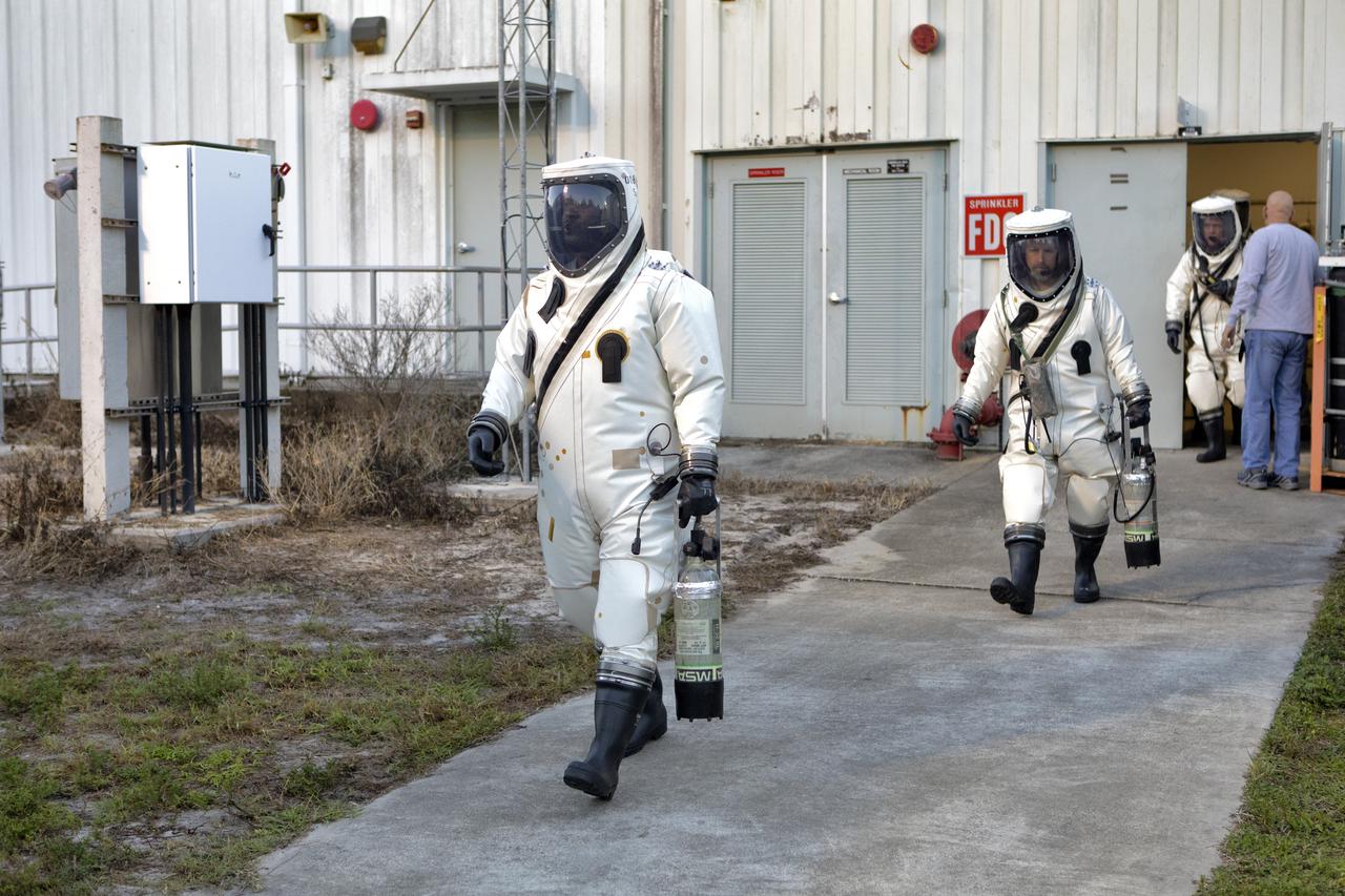
Operators wearing Self-Contained Atmospheric Protective Ensemble (SCAPE) suits depart the suit-up room at the Multi-Payload Processing Facility (MPPF) at NASA's Kennedy Space Center in Florida on Oct. 31, 2018. SCAPE operators are preparing to participate in a hypergolic systems hot flow test at the MPPF. The test will serve as operational validation of the hypergol subsystem and demonstrate that the hypergols subsystem can service the Orion spacecraft, flow fuel at the required rates, drain and de-service the system, and meet the intended timeline. SCAPE suite are used in operations involving toxic propellants and are supplied with air either through a hardline or through a self-contained environmental control unit.
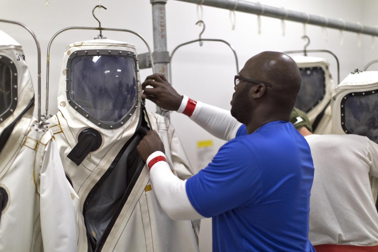
An operator prepares to don a Self-Contained Atmospheric Protective Ensemble (SCAPE) suit inside a room in the Multi-Payload Processing Facility (MPPF) at NASA's Kennedy Space Center in Florida on Oct. 31, 2018. SCAPE operators, wearing the suits, will participate in a hypergolic systems hot flow test at the MPPF. The test will serve as operational validation of the hypergol subsystem and demonstrate that the hypergols subsystem can service the Orion spacecraft, flow fuel at the required rates, drain and de-service the system, and meet the intended timeline. SCAPE suite are used in operations involving toxic propellants and are supplied with air either through a hardline or through a self-contained environmental control unit.
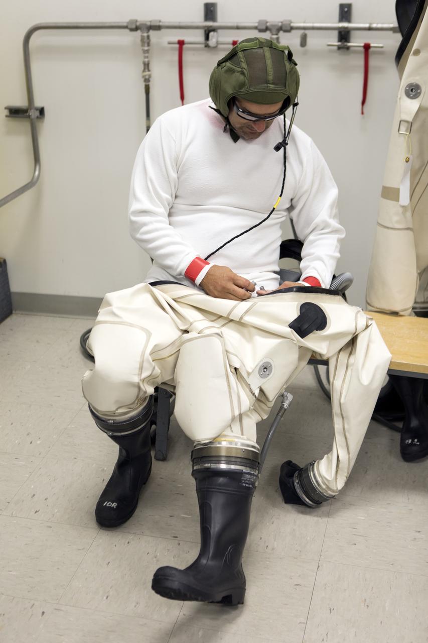
An operator dons a Self-Contained Atmospheric Protective Ensemble (SCAPE) suit inside a room in the Multi-Payload Processing Facility (MPPF) at NASA's Kennedy Space Center in Florida on Oct. 31, 2018. SCAPE operators, wearing the suits, will participate in a hypergolic systems hot flow test at the MPPF. The test will serve as operational validation of the hypergol subsystem and demonstrate that the hypergols subsystem can service the Orion spacecraft, flow fuel at the required rates, drain and de-service the system, and meet the intended timeline. SCAPE suite are used in operations involving toxic propellants and are supplied with air either through a hardline or through a self-contained environmental control unit.
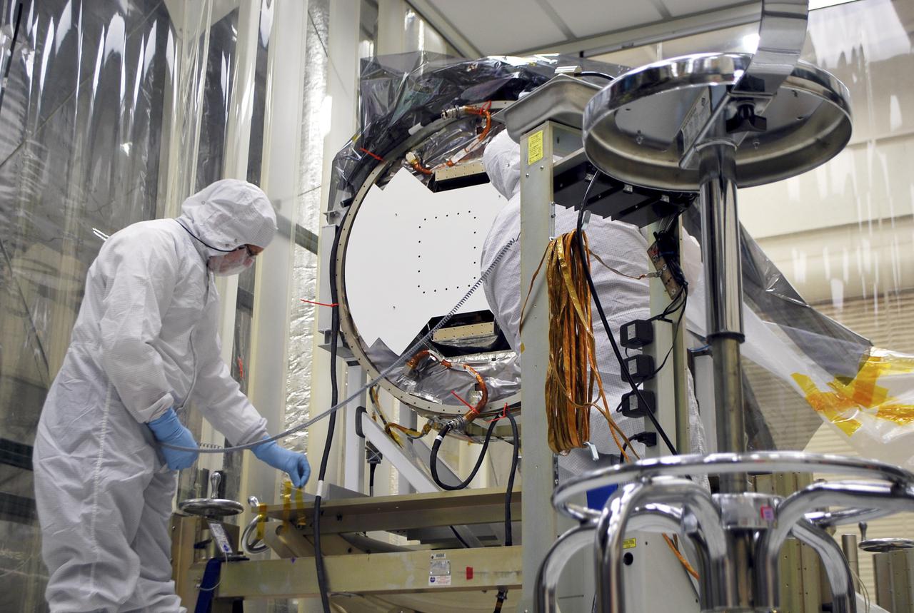
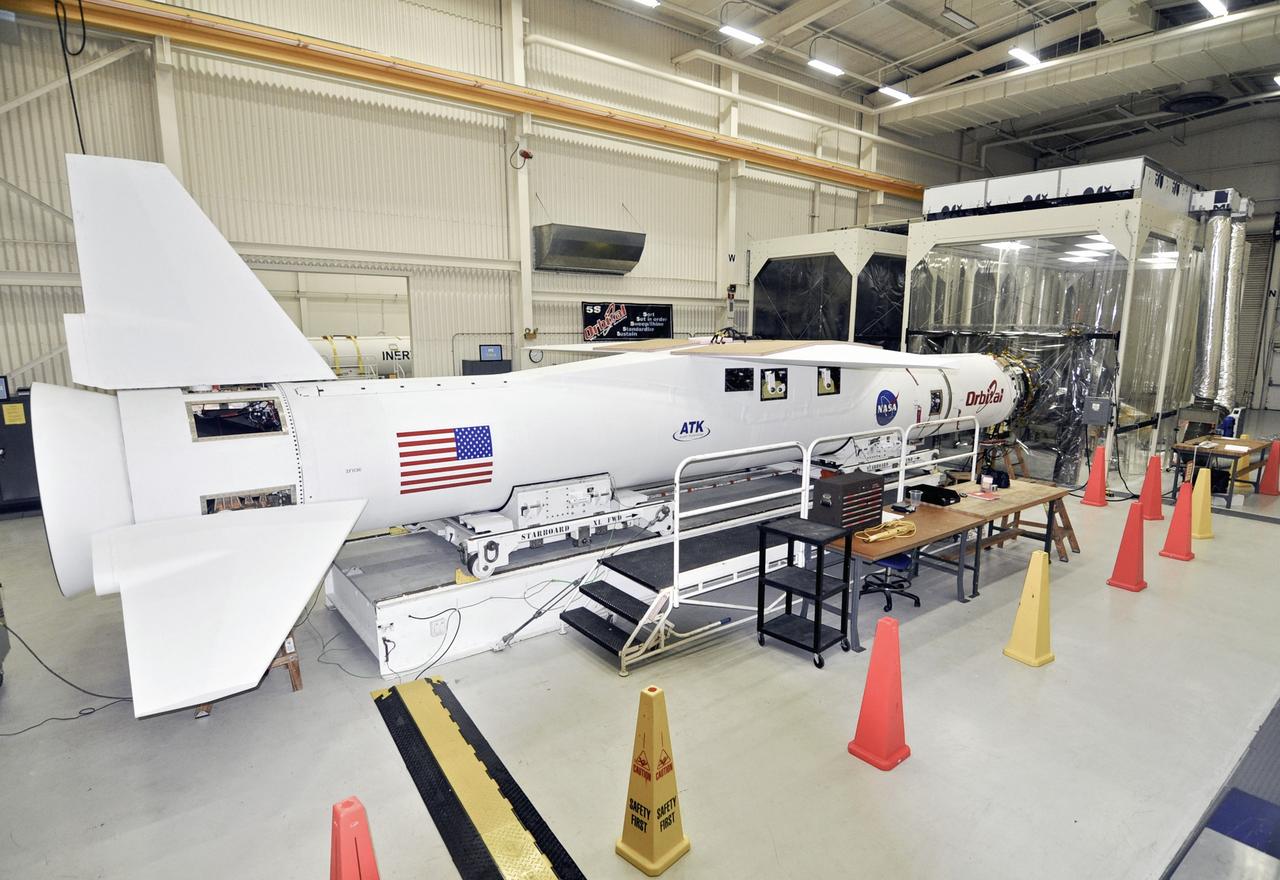
VANDENBERG AIR FORCE BASE, Calif. -- Following the first Interface Verification Test, a technician removes cables providing the electrical connections between the Interface Region Imaging Spectrograph, or IRIS, spacecraft and the Orbital Sciences Corp. Pegasus XL launch vehicle. Completion of the test paves the way for the standalone IRIS mission simulations. IRIS will open a new window of discovery by tracing the flow of energy and plasma through the chromospheres and transition region into the sun’s corona using spectrometry and imaging. IRIS fills a crucial gap in our ability to advance studies of the sun-to-Earth connection by tracing the flow of energy and plasma through the foundation of the corona and the region around the sun known as the heliosphere. Photo credit: VAFB_Randy Beaudoin
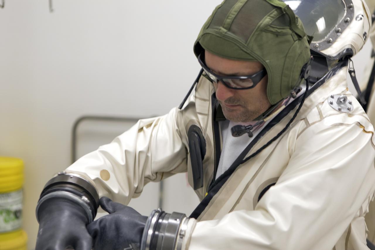
An operator dons a Self-Contained Atmospheric Protective Ensemble (SCAPE) suit inside a room in the Multi-Payload Processing Facility (MPPF) at NASA's Kennedy Space Center in Florida on Oct. 31, 2018. SCAPE operators, wearing the suits, will participate in a hypergolic systems hot flow test at the MPPF. The test will serve as operational validation of the hypergol subsystem and demonstrate that the hypergols subsystem can service the Orion spacecraft, flow fuel at the required rates, drain and de-service the system, and meet the intended timeline. SCAPE suite are used in operations involving toxic propellants and are supplied with air either through a hardline or through a self-contained environmental control unit.
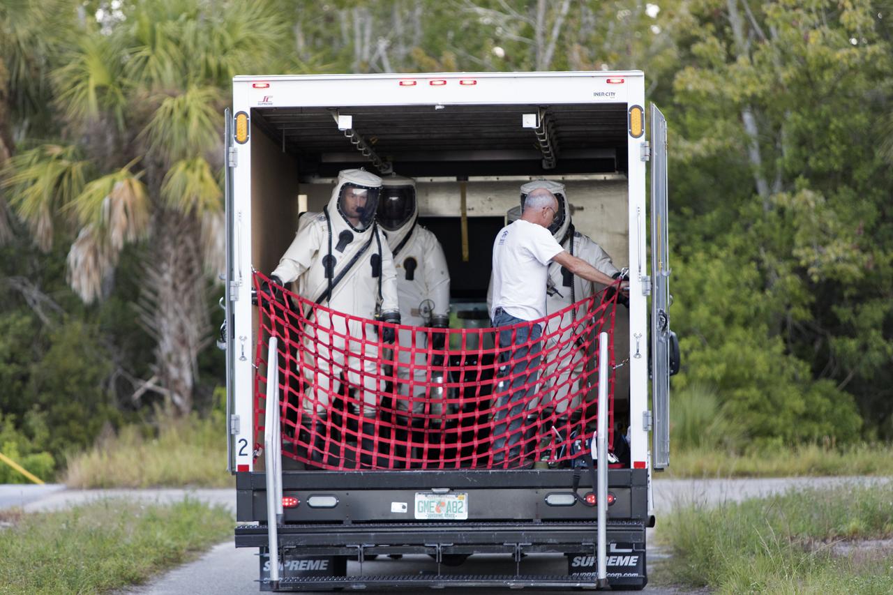
Operators wearing Self-Contained Atmospheric Protective Ensemble (SCAPE) suits are inside a transport vehicle near the Multi-Payload Processing Facility (MPPF) at NASA's Kennedy Space Center in Florida on Oct. 31, 2018. SCAPE operators, wearing the suits, will participate in a hypergolic systems hot flow test at the MPPF. The test will serve as operational validation of the hypergol subsystem and demonstrate that the hypergols subsystem can service the Orion spacecraft, flow fuel at the required rates, drain and de-service the system, and meet the intended timeline. SCAPE suite are used in operations involving toxic propellants and are supplied with air either through a hardline or through a self-contained environmental control unit.
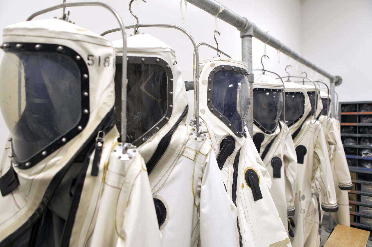
Self-Contained Atmospheric Protective Ensemble (SCAPE) suits are hanging in a row inside the Multi-Payload Processing Facility (MPPF) at NASA's Kennedy Space Center in Florida on Oct. 31, 2018. SCAPE operators will don the suits and then participate in a hypergolic systems hot flow test at the MPPF. The test will serve as operational validation of the hypergol subsystem and demonstrate that the hypergols subsystem can service the Orion spacecraft, flow fuel at the required rates, drain and de-service the system, and meet the intended timeline. SCAPE suite are used in operations involving toxic propellants and are supplied with air either through a hardline or through a self-contained environmental control unit.
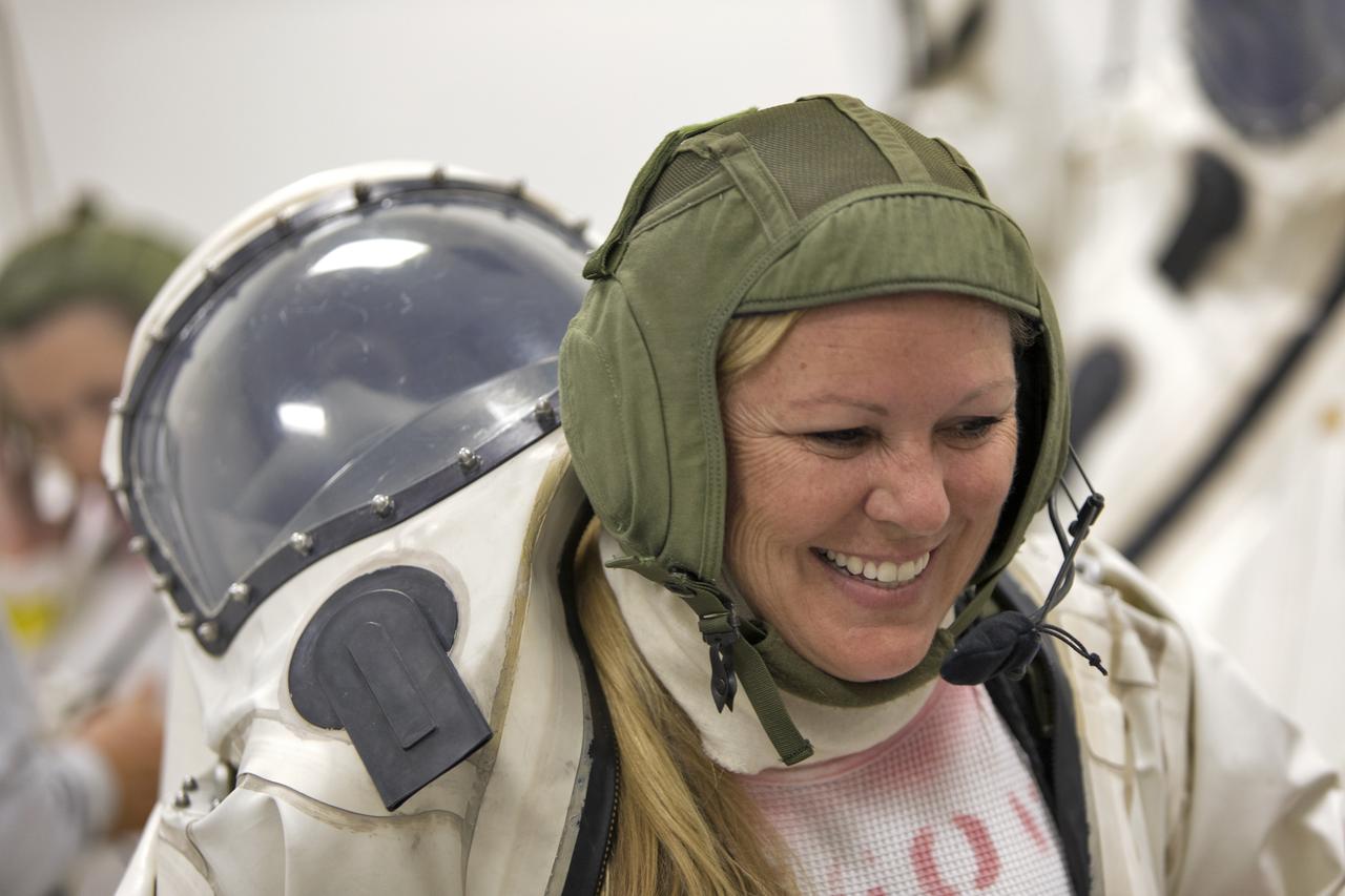
An operator dons a Self-Contained Atmospheric Protective Ensemble (SCAPE) suit inside a room in the Multi-Payload Processing Facility (MPPF) at NASA's Kennedy Space Center in Florida on Oct. 31, 2018. SCAPE operators, wearing the suits, will participate in a hypergolic systems hot flow test at the MPPF. The test will serve as operational validation of the hypergol subsystem and demonstrate that the hypergols subsystem can service the Orion spacecraft, flow fuel at the required rates, drain and de-service the system, and meet the intended timeline. SCAPE suite are used in operations involving toxic propellants and are supplied with air either through a hardline or through a self-contained environmental control unit.
VANDENBERG AIR FORCE BASE, Calif. -- Following the first Interface Verification Test, a technician removes cables providing the electrical connections between the Interface Region Imaging Spectrograph, or IRIS, spacecraft and the Orbital Sciences Corp. Pegasus XL launch vehicle. Completion of the test paves the way for the standalone IRIS mission simulations. IRIS will open a new window of discovery by tracing the flow of energy and plasma through the chromospheres and transition region into the sun’s corona using spectrometry and imaging. IRIS fills a crucial gap in our ability to advance studies of the sun-to-Earth connection by tracing the flow of energy and plasma through the foundation of the corona and the region around the sun known as the heliosphere. Photo credit: VAFB_Randy Beaudoin
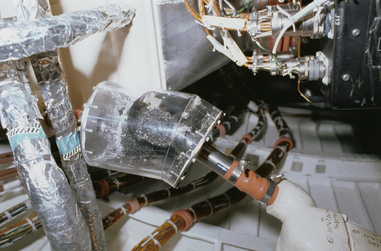
STS040-34-001 (5-14 June 1991) --- This 35mm scene shows a close-up of a prototype filter designed to remove contamination from air and water, before it flows into the Orbiter's humidity separators. This experiment is part of Development Test Objective (DTO) 647, Water Separator Filter Performance Evaluation. Astronauts Bryan D. O'Connor, mission commander, and Sidney M. Gutierrez, pilot, carried out the test and down linked television to the ground for engineering analysis.
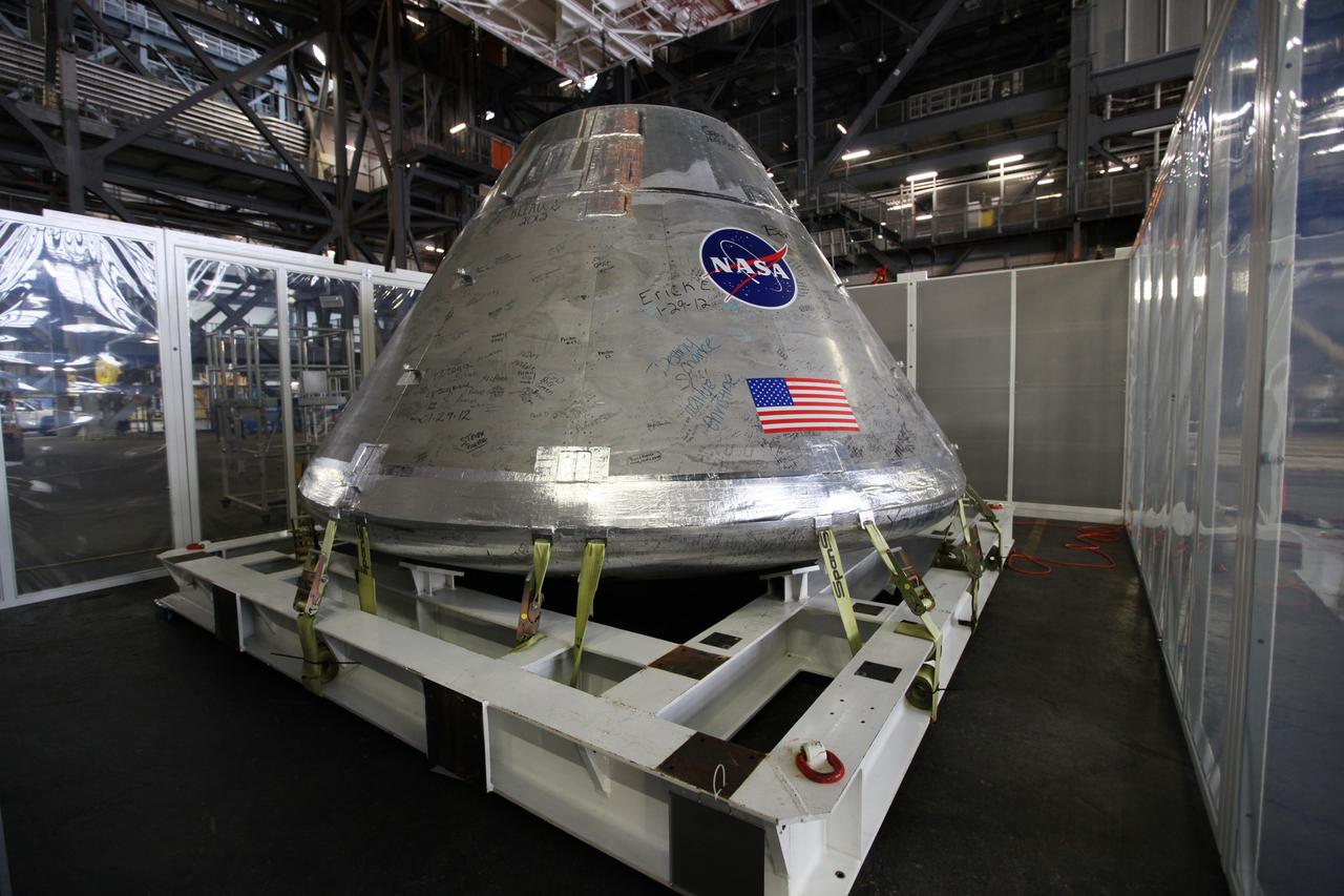
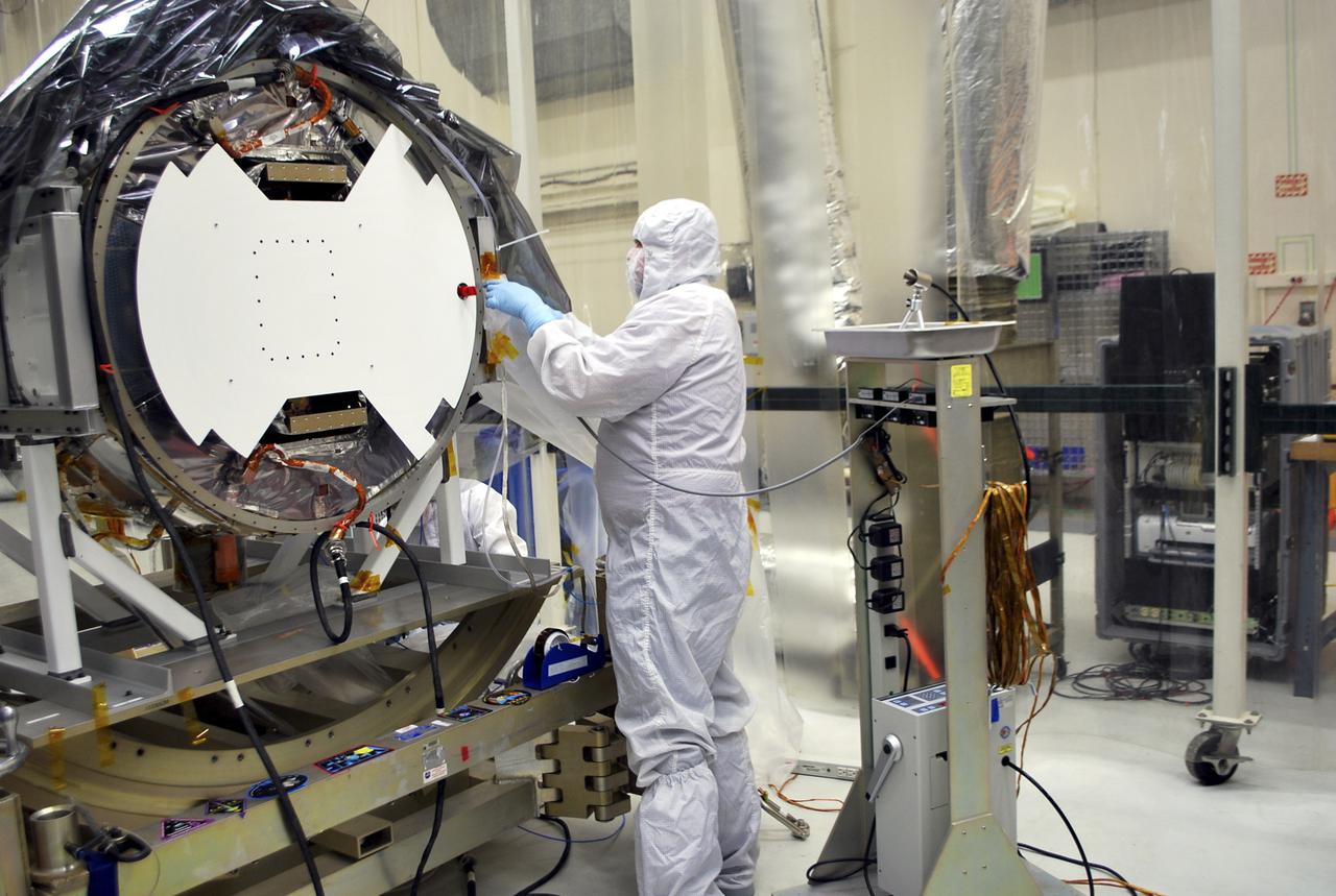
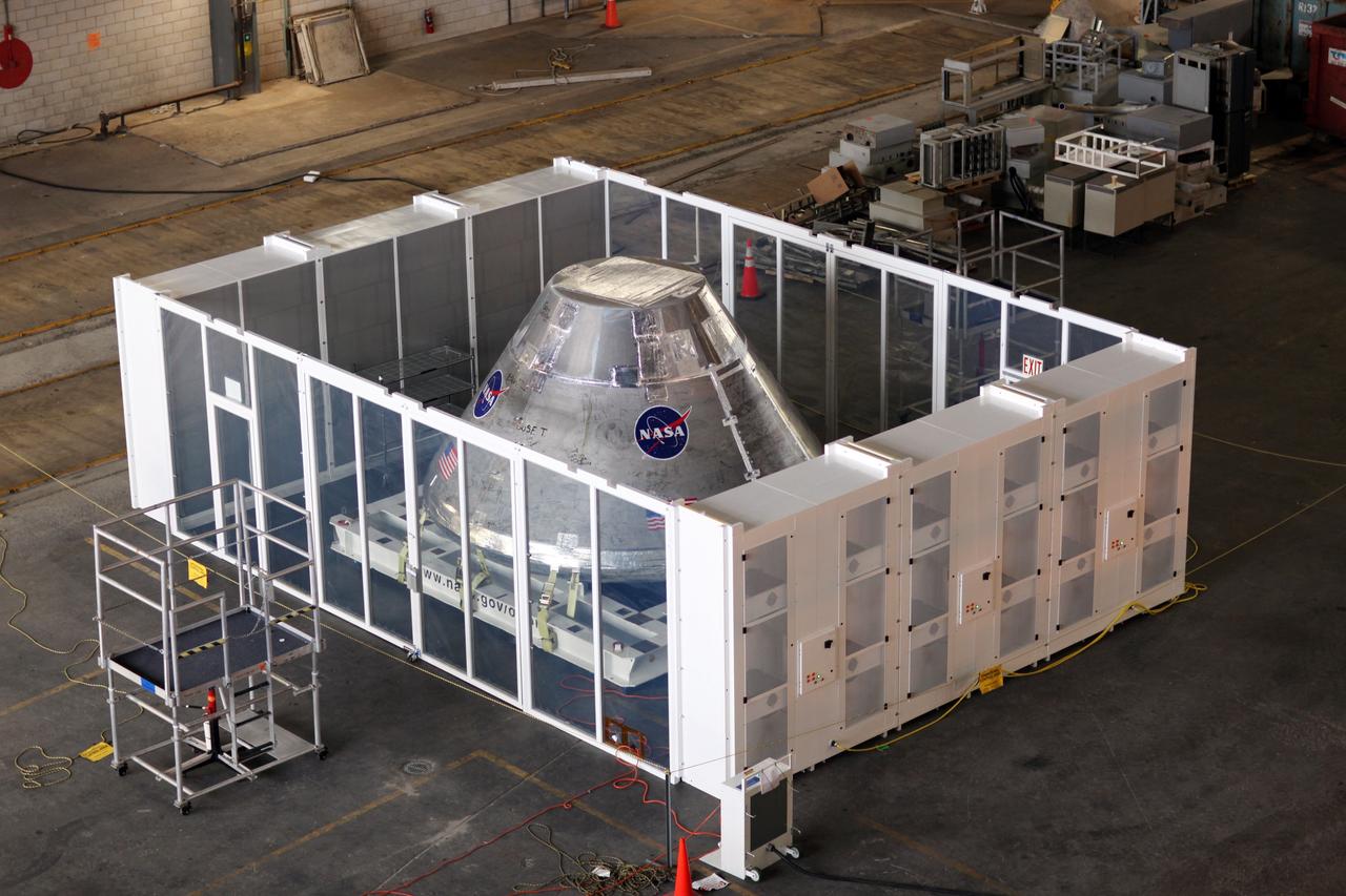
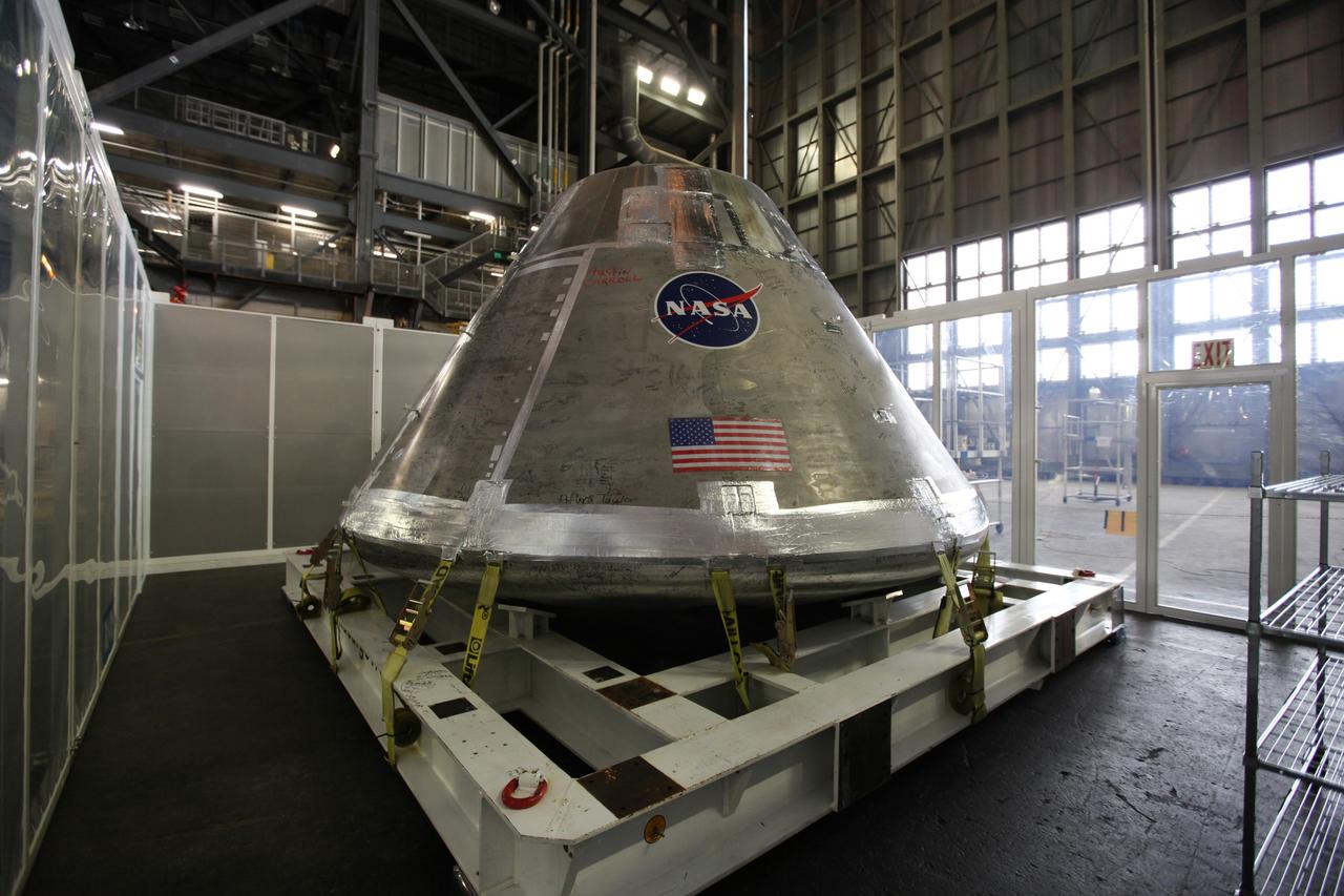
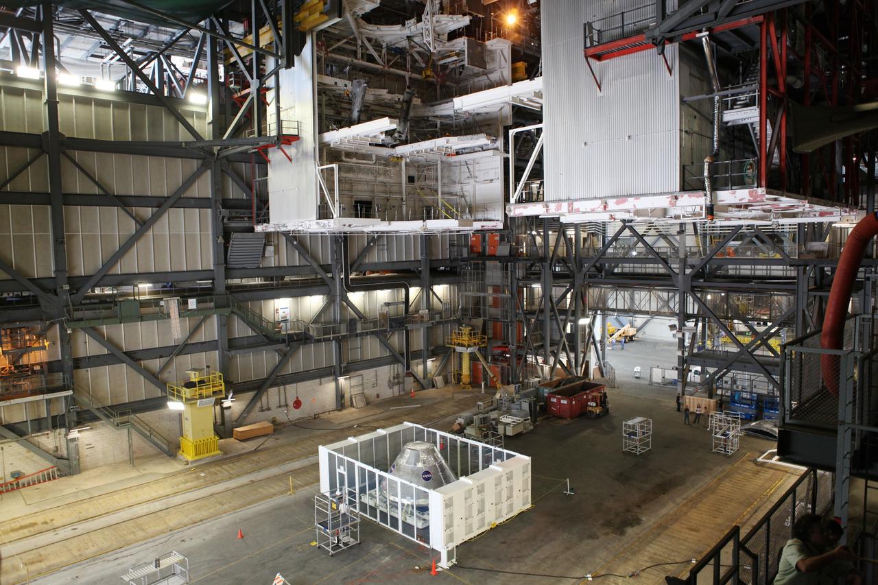
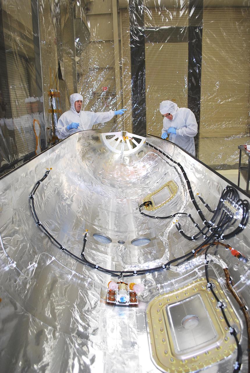
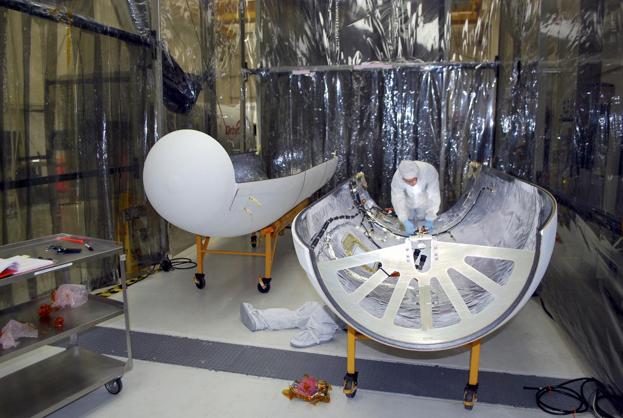
CAPE CANAVERAL, Fla. - An Orion test capsule sits inside a temporary clean room in High Bay 3 of the Vehicle Assembly Building at NASA's Kennedy Space Center in Florida during testing. The clean room, built by Astrotech, uses air flow produced by two banks of fans to keep particles from settling on the surface of a spacecraft during processing. Engineers are considering using the design in the future to protect the spacecraft after it is secured to the top of the Space Launch System rocket. Photo credit: NASA/Dmitri Gerondidakis

CAPE CANAVERAL, Fla. - An Orion test capsule sits inside a temporary clean room in High Bay 3 of the Vehicle Assembly Building at NASA's Kennedy Space Center in Florida during testing. The clean room, built by Astrotech, uses air flow produced by two banks of fans to keep particles from settling on the surface of a spacecraft during processing. Engineers are considering using the design in the future to protect the spacecraft after it is secured to the top of the Space Launch System rocket. Photo credit: NASA/Dmitri Gerondidakis
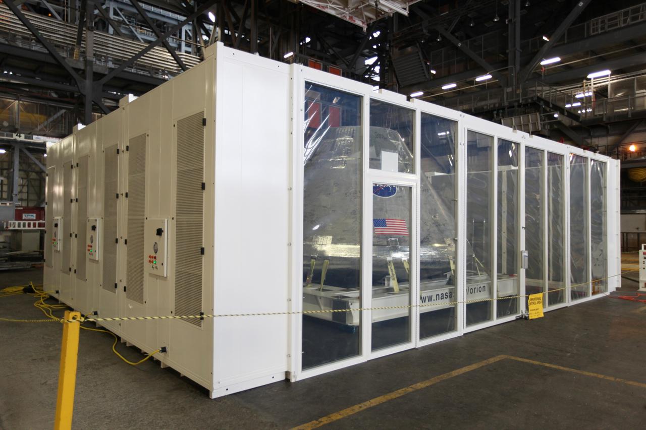
CAPE CANAVERAL, Fla. - An Orion test capsule sits inside a temporary clean room in High Bay 3 of the Vehicle Assembly Building at NASA's Kennedy Space Center in Florida during testing. The clean room, built by Astrotech, uses air flow produced by two banks of fans to keep particles from settling on the surface of a spacecraft during processing. Engineers are considering using the design in the future to protect the spacecraft after it is secured to the top of the Space Launch System rocket. Photo credit: NASA/Dmitri Gerondidakis
CAPE CANAVERAL, Fla. - An Orion test capsule sits inside a temporary clean room in High Bay 3 of the Vehicle Assembly Building at NASA's Kennedy Space Center in Florida during testing. The clean room, built by Astrotech, uses air flow produced by two banks of fans to keep particles from settling on the surface of a spacecraft during processing. Engineers are considering using the design in the future to protect the spacecraft after it is secured to the top of the Space Launch System rocket. Photo credit: NASA/Dmitri Gerondidakis
CAPE CANAVERAL, Fla. - An Orion test capsule sits inside a temporary clean room in High Bay 3 of the Vehicle Assembly Building at NASA's Kennedy Space Center in Florida during testing. The clean room, built by Astrotech, uses air flow produced by two banks of fans to keep particles from settling on the surface of a spacecraft during processing. Engineers are considering using the design in the future to protect the spacecraft after it is secured to the top of the Space Launch System rocket. Photo credit: NASA/Dmitri Gerondidakis
CAPE CANAVERAL, Fla. - An Orion test capsule sits inside a temporary clean room in High Bay 3 of the Vehicle Assembly Building at NASA's Kennedy Space Center in Florida during testing. The clean room, built by Astrotech, uses air flow produced by two banks of fans to keep particles from settling on the surface of a spacecraft during processing. Engineers are considering using the design in the future to protect the spacecraft after it is secured to the top of the Space Launch System rocket. Photo credit: NASA/Dmitri Gerondidakis
Screwjacks located on the exterior of the second throat section in the 10- by 10-Foot Supersonic Wind Tunnel at the National Aeronautics and Space Administration (NASA) Lewis Research Center. The 10- by 10 tunnel was the most powerful propulsion wind tunnel in the country when it began operating in 1956. The facility can generate wind speeds from Mach 3 to 3.5. A flexible wall nozzle located just upstream from the test section can be adjusted using screw jacks to produce the desired air flow. The 61-foot long second throat, seen here from the outside, was located just beyond the test section. It slows the supersonic air flow down to prevent shock waves. The second throat’s side walls can be adjusted up to three inches on each side using these electrically-driven screwjacks. The air and the 1.25-inch thick walls are cooled by water injection. During the 1960s the 10- by 10-foot tunnel supported the development of virtually all US launch vehicle systems. It was used for Atlas-Centaur, Saturn rockets, and Atlas-Agena testing.
The 10- by 10-Foot Supersonic Wind Tunnel at the NACA Lewis Flight Propulsion Laboratory was built under the Congressional Unitary Plan Act which coordinated wind tunnel construction at the NACA, Air Force, industry, and universities. The 10- by 10, which began operation in 1956, was the largest of the three NACA tunnels built under the act. Researchers could test engines up to five feet in diameter in the 10- by 10-foot test section. A 250,000-horsepower axial-flow compressor fan can generate airflows up to Mach 3.5 through the test section. The incoming air must be dehumidified and cooled so that the proper conditions are present for the test. A large air dryer with 1,890 tons of activated alumina soaks up 1.5 tons of water per minute from the airflow. A cooling apparatus equivalent to 250,000 household air conditioners is used to cool the air. The air heater is located just upstream from the test section. Natural gas is combusted in the tunnel to increase the air temperature. The system could only be employed when the tunnel was run in its closed-circuit propulsion mode.
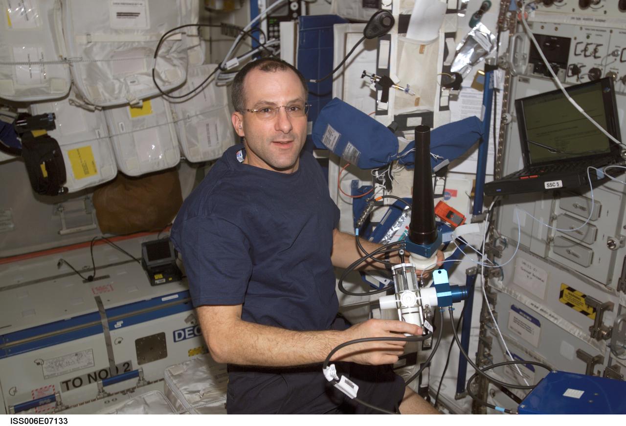
In this International Space Station (ISS) onboard photo, Expedition Six Science Officer Donald R. Pettit works to set up the Pulmonary Function in Flight (PuFF) experiment hardware in the Destiny Laboratory. Expedition Six is the fourth and final crew to perform the PuFF experiment. The PuFF experiment was developed to better understand what effects long term exposure to microgravity may have on the lungs. The focus is on measuring changes in the everness of gas exchange in the lungs, and on detecting changes in respiratory muscle strength. It allows astronauts to measure blood flow through the lungs, the ability of the lung to take up oxygen, and lung volumes. Each PuFF session includes five lung function tests, which involve breathing only cabin air. For each planned extravehicular (EVA) activity, a crew member performs a PuFF test within one week prior to the EVA. Following the EVA, those crew members perform another test to document the effect of exposure of the lungs to the low-pressure environment of the space suits. This experiment utilizes the Gas Analyzer System for Metabolic Analysis Physiology, or GASMAP, located in the Human Research Facility (HRF), along with a variety of other Puff equipment including a manual breathing valve, flow meter, pressure-flow module, pressure and volume calibration syringes, and disposable mouth pieces.
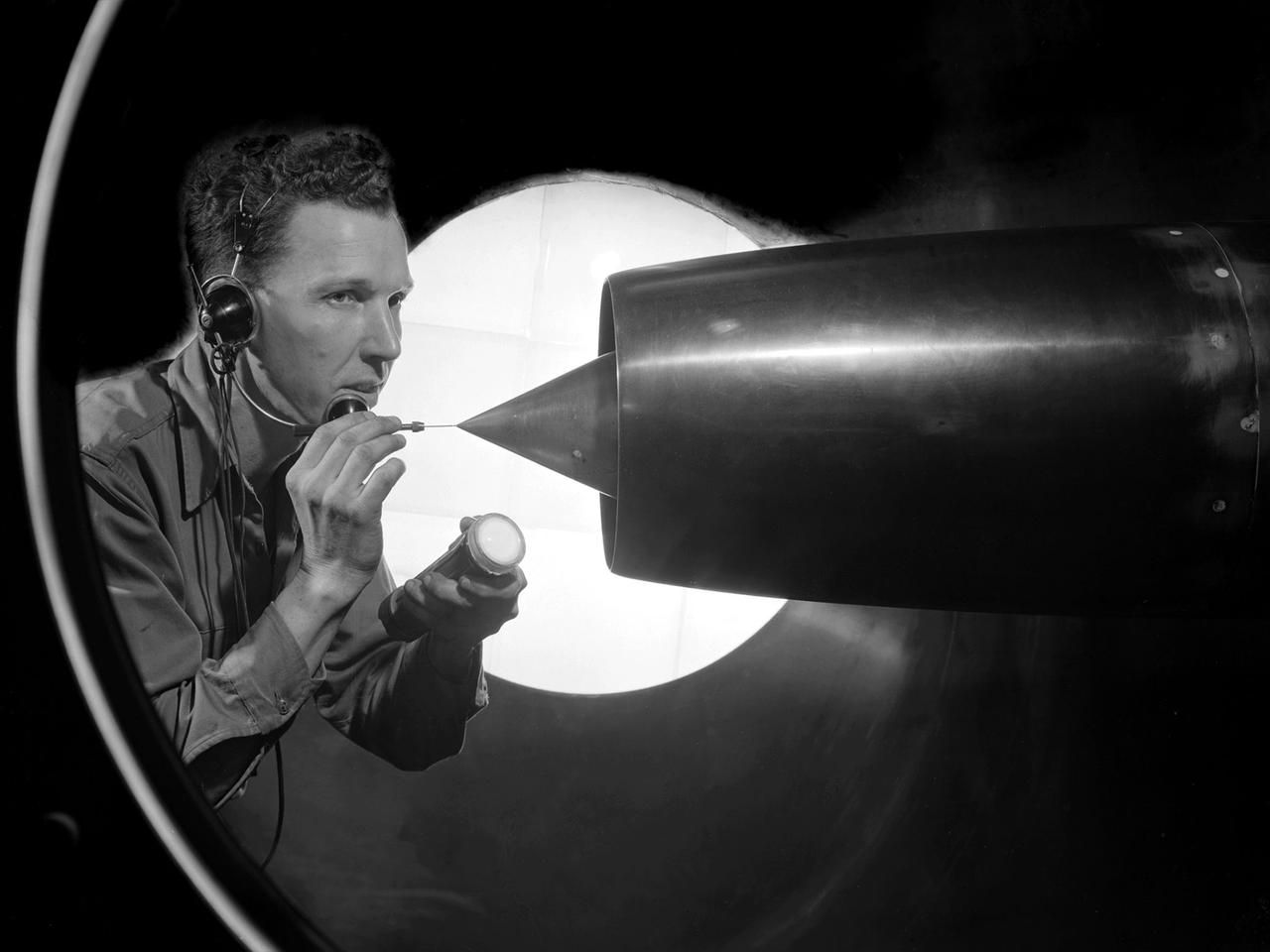
A technician at the National Advisory Committee for Aeronautics (NACA) Lewis Flight Propulsion Laboratory cleans the pitot tube on a 16-inch diameter ramjet in the 8- by 6-Foot Supersonic Wind Tunnel. Pitot tubes are a measurement device used to determine the flow velocity at a specific location in the air stream, not the average velocity of the entire wind stream. NACA Lewis was in the midst of a multi-year program to determine the feasibility of ramjets and design improvements that could be employed for all models. The advantage of the ramjet was its ability to process large volumes of combustion air, resulting in the burning of fuel at the optimal stoichiometric temperatures. This was not possible with turbojets. The higher the Mach number, the more efficient the ramjet operated. The 8- by 6 Supersonic Wind Tunnel had been in operation for just over one year when this photograph was taken. The facility was the NACA’s largest supersonic tunnel and the only facility capable of running an engine at supersonic speeds. The 8- by 6 tunnel was also equipped with a Schlieren camera system that captured the air flow gradient as it passes over the test setup. The ramjet tests in the 8- by 6 tunnel complemented the NACA Lewis investigations using aircraft, the Altitude Wind Tunnel and smaller supersonic tunnels. Researchers studied the ramjet’s performance at different speeds and varying angles -of -attack.
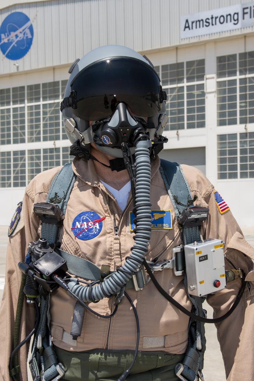
NASA research pilot Wayne Ringelberg wears a U.S. Air Force configuration of the NASA Jet Propulsion Laboratory in California prototype mask, which uses laser sensors to determine levels of carbon dioxide and water exhaled inside the mask. This prototype was tested in conjunction with the current VigilOX system, which measures the pilot’s oxygen concentration, breathing pressures and flow rates. This and the U.S. Navy configuration was used in the Pilot Breathing Assessment program at NASA’s Armstrong Flight Research Center in California.
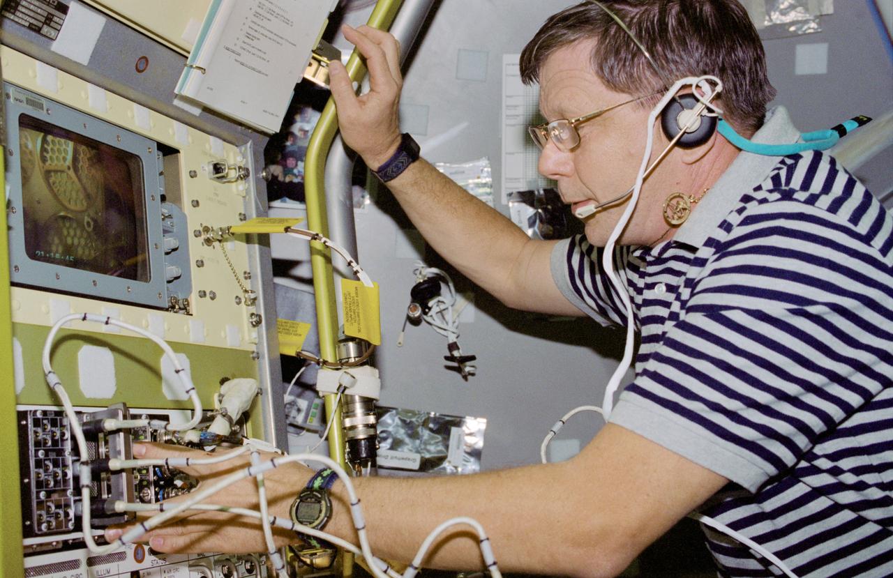
STS083-346-024 (4-8 April 1997) --- Payload specialist Roger K. Crouch performs the activation for the Mid Deck Glove Box (MGBX). Made to accommodate a variety of hardware and materials testing, the facility offers physical isolation and a negative air pressure environment so that items that are not suitable for handling in the open Spacelab can be protected. One experiment that was performed on STS-83 is the Internal Flows in a Free Drop (IFFD), an experiment that investigates rotation and position control of drops by varying acoustic pressures.
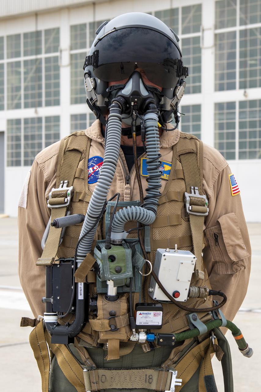
NASA research pilot Jim Less wears a U.S. Navy harness configuration with the NASA Jet Propulsion Laboratory in California prototype mask, which uses laser sensors to determine levels of carbon dioxide and water exhaled inside the mask. This prototype was tested in conjunction with the current VigilOX system, which measures the pilot’s oxygen concentration, breathing pressures and flow rates. This and the U.S. Air Force configuration was used in the Pilot Breathing Assessment program at NASA’s Armstrong Flight Research Center in California.
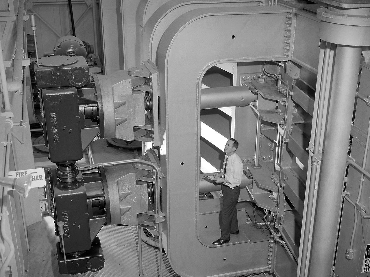
An engineer examines the main compressor for the 10- by 10-Foot Supersonic Wind Tunnel at the National Advisory Committee for Aeronautics (NACA) Lewis Flight Propulsion Laboratory. The engineers were preparing the new wind tunnel for its initial runs in early 1956. The 10- by 10 was the most powerful propulsion wind tunnel in the nation. The facility was part of Congress’ Unitary Plan Act which coordinated wind tunnel construction at the NACA, Air Force, industry, and universities. The 10- by 10 was the largest of the three NACA tunnels built under the act. The 20-foot diameter eight-stage axial flow compressor, seen in this photograph, could generate air flows up to Mach 2.5 through the test section. The stainless steel compressor had 584 blades ranging from 1.8 to 3.25 feet in length. This main compressor was complemented by a secondary axial flow compressor. Working in tandem the two could generate wind streams up to Mach 3.5. The Cleveland Chamber of Commerce presented NACA Lewis photographer Bill Bowles with a second place award for this photograph in their Business and Professional category. The photograph was published in October 1955 edition of its periodical, The Clevelander, which highlighted local professional photographers. Fellow Lewis photographer Gene Giczy won second place in another category for a photograph of Cleveland Municipal Airport.
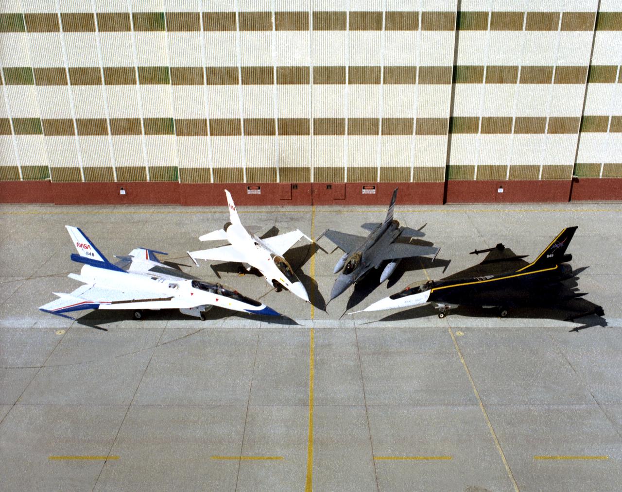
Four different versions of the F-16 were used by Dryden in the 1990s. On the left and right sides are two F-16XLs. On the left is the F-16XL #2 (NASA 848), which is the two-seat version, used for advanced laminar flow studies until late 1996. On the right is the single-seat F-16XL #1 (NASA 849), used for laminar flow research and sonic boom research. (Laminar flow refers to smooth airflow over a wing, which increases lift and reduces drag compared to turbulent airflow). Between them at center left is an F-16A (NASA 816), the only civilian operated F-16. Next to it at center right is the U.S. Air Force Advance Fighter Technology Integration (AFTI) F-16, a program to test new sensor and control technologies for future fighter aircraft. Both F-16XLs are in storage at Dryden. The F-16A was never flown at Dryden, and was parked by the entrance to the center. The AFTI F-16 is in the Air Force Museum.
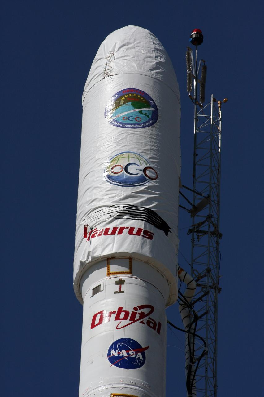
VANDENBERG AIR FORCE BASE, Calif. -- On Launch Complex 576-E at Vandenberg Air Force Base in California, NASA's Orbiting Carbon Observatory, or OCO, spacecraft awaits a GN2 instrument purge flow test in preparation for launch Feb. 24. The spacecraft sits atop Orbital Sciences' Taurus XL rocket. At right is a portion of the umbilical tower attached to the upper stack. The spacecraft will collect precise global measurements of carbon dioxide (CO2) in the Earth's atmosphere. Scientists will analyze OCO data to improve our understanding of the natural processes and human activities that regulate the abundance and distribution of this important greenhouse gas. Photo courtesy of Jim Stowers, Orbital Sciences
The 8- by 6-Foot Supersonic Wind Tunnel at the National Advisory Committee for Aeronautics (NACA) Lewis Flight Propulsion Laboratory was the largest supersonic wind tunnel in the nation at the time and the only one able to test full-scale engines at supersonic speeds. The 8- by 6 was designed as a non-return and open-throat tunnel. A large compressor created the air flow at one end of the tunnel, squeezed the flow to increase its velocity just before the test section, then reduced the velocity, and expelled it into the atmosphere at the other end of the tunnel. This design worked well for initial aerodynamic testing, but the local community was literally rattled by the noise and vibrations when researchers began running engines in the test section in January 1950. The NACA’s most modern wind tunnel was referred to as “an 87,000-horsepower bugle aimed at the heart of Cleveland.” NACA Lewis responded to the complaints by adding an acoustic housing at the end of the tunnel to dampen the noise. The structure included resonator chambers and a reinforced concrete muffler structure. Modifications continued over the years. A return leg was added, and a second test section, 9 -by 15-foot, was incorporated in the return leg in the 1960s. Since its initial operation in 1948, the 8- by 6-foot tunnel has been aggressively used to support the nation's aeronautics and space programs for the military, industry, and academia.
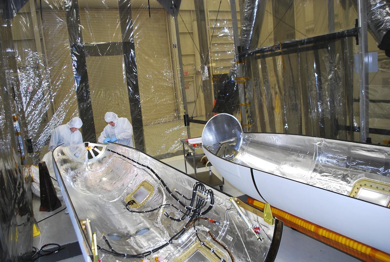
VANDENBERG AIR FORCE BASE, Calif. -- Technicians inside Building 1555 conduct inspection, cleaning and electrical testing on half of a payload fairing for the Orbital Sciences Corp. Pegasus XL rocket that will launch the Interface Region Imaging Spectrograph, or IRIS, spacecraft. The fairing will be fitted to the nose of the Pegasus to protect the spacecraft from atmospheric heating and stress during launch. IRIS will open a new window of discovery by tracing the flow of energy and plasma through the chromospheres and transition region into the sun’s corona using spectrometry and imaging. IRIS fills a crucial gap in our ability to advance studies of the sun-to-Earth connection by tracing the flow of energy and plasma through the foundation of the corona and the region around the sun known as the heliosphere. Photo credit: VAFB_Randy Beaudoin
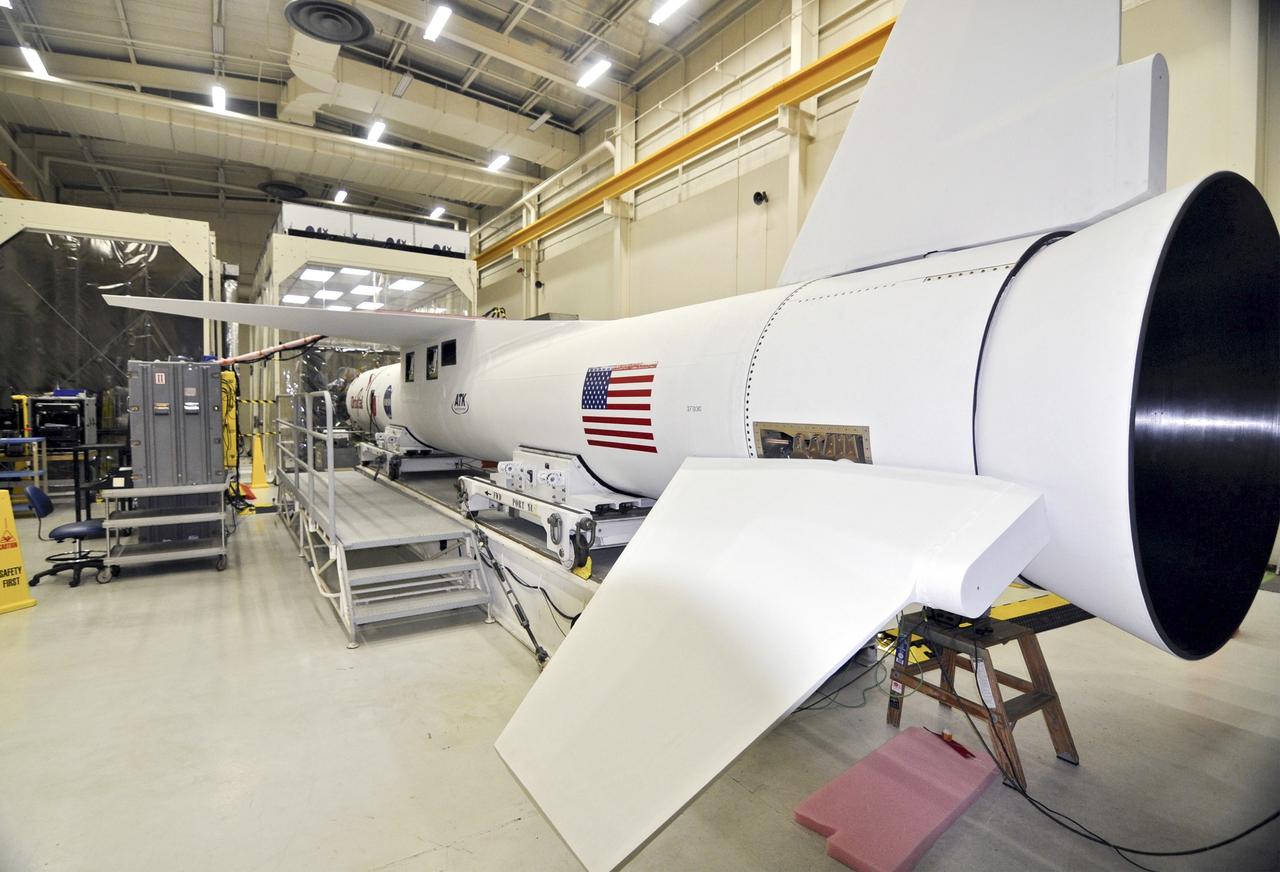
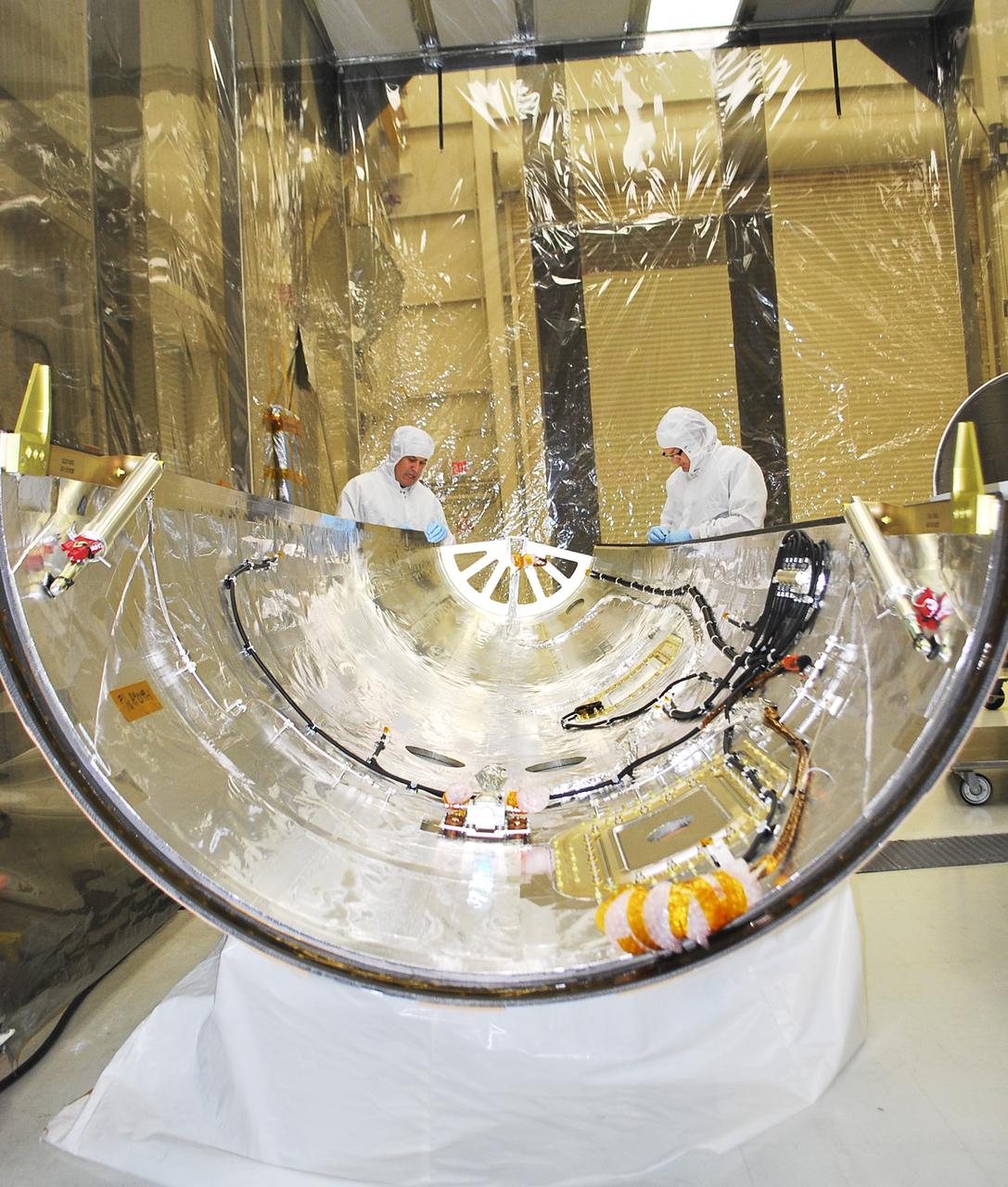
VANDENBERG AIR FORCE BASE, Calif. -- The Interface Region Imaging Spectrograph, or IRIS, is being readied for mating to the Orbital Sciences Corp. Pegasus XL rocket that will launch the spacecraft. A fairing will be fitted to the nose of the Pegasus to protect the spacecraft from atmospheric heating and stress during launch. Upcoming work includes electrical verification testing. IRIS will open a new window of discovery by tracing the flow of energy and plasma through the chromospheres and transition region into the sun’s corona using spectrometry and imaging. IRIS fills a crucial gap in our ability to advance studies of the sun-to-Earth connection by tracing the flow of energy and plasma through the foundation of the corona and the region around the sun known as the heliosphere. Photo credit: VAFB/Randy Beaudoin
VANDENBERG AIR FORCE BASE, Calif. -- Technicians inside Building 1555 conduct inspection, cleaning and electrical testing on half of a payload fairing for the Orbital Sciences Corp. Pegasus XL rocket that will launch the Interface Region Imaging Spectrograph, or IRIS, spacecraft. The fairing will be fitted to the nose of the Pegasus to protect the spacecraft from atmospheric heating and stress during launch. IRIS will open a new window of discovery by tracing the flow of energy and plasma through the chromospheres and transition region into the sun’s corona using spectrometry and imaging. IRIS fills a crucial gap in our ability to advance studies of the sun-to-Earth connection by tracing the flow of energy and plasma through the foundation of the corona and the region around the sun known as the heliosphere. Photo credit: VAFB_Randy Beaudoin
VANDENBERG AIR FORCE BASE, Calif. -- The Interface Region Imaging Spectrograph, or IRIS, is being readied for mating to the Orbital Sciences Corp. Pegasus XL rocket that will launch the spacecraft. A fairing will be fitted to the nose of the Pegasus to protect the spacecraft from atmospheric heating and stress during launch. Upcoming work includes electrical verification testing. IRIS will open a new window of discovery by tracing the flow of energy and plasma through the chromospheres and transition region into the sun’s corona using spectrometry and imaging. IRIS fills a crucial gap in our ability to advance studies of the sun-to-Earth connection by tracing the flow of energy and plasma through the foundation of the corona and the region around the sun known as the heliosphere. Photo credit: VAFB/Randy Beaudoin
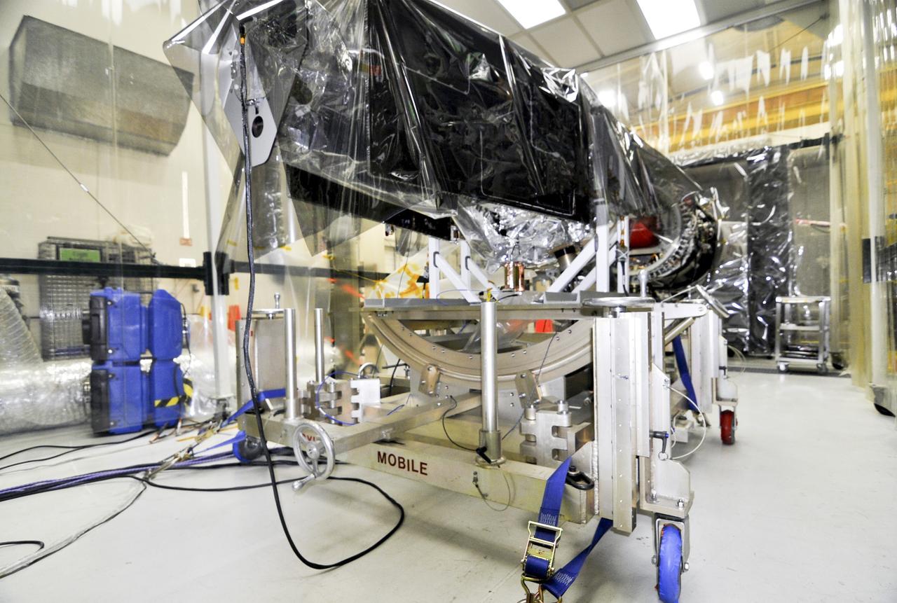
VANDENBERG AIR FORCE BASE, Calif. -- The Interface Region Imaging Spectrograph, or IRIS, is being readied for mating to the Orbital Sciences Corp. Pegasus XL rocket that will launch the spacecraft. IRIS will be covered in a fairing after it's connected to the nose of the Pegasus to protect the spacecraft from atmospheric heating and stress during launch. Upcoming work includes electrical verification testing. IRIS will open a new window of discovery by tracing the flow of energy and plasma through the chromospheres and transition region into the sun’s corona using spectrometry and imaging. IRIS fills a crucial gap in our ability to advance studies of the sun-to-Earth connection by tracing the flow of energy and plasma through the foundation of the corona and the region around the sun known as the heliosphere. Photo credit: VAFB/Randy Beaudoin
VANDENBERG AIR FORCE BASE, Calif. -- Technicians inside Building 1555 conduct inspection, cleaning and electrical testing on half of a payload fairing for the Orbital Sciences Corp. Pegasus XL rocket that will launch the Interface Region Imaging Spectrograph, or IRIS, spacecraft. The fairing will be fitted to the nose of the Pegasus to protect the spacecraft from atmospheric heating and stress during launch. IRIS will open a new window of discovery by tracing the flow of energy and plasma through the chromospheres and transition region into the sun’s corona using spectrometry and imaging. IRIS fills a crucial gap in our ability to advance studies of the sun-to-Earth connection by tracing the flow of energy and plasma through the foundation of the corona and the region around the sun known as the heliosphere. Photo credit: VAFB_Randy Beaudoin
VANDENBERG AIR FORCE BASE, Calif. -- Technicians inside Building 1555 conduct inspection, cleaning and electrical testing on half of a payload fairing for the Orbital Sciences Corp. Pegasus XL rocket that will launch the Interface Region Imaging Spectrograph, or IRIS, spacecraft. The fairing will be fitted to the nose of the Pegasus to protect the spacecraft from atmospheric heating and stress during launch. IRIS will open a new window of discovery by tracing the flow of energy and plasma through the chromospheres and transition region into the sun’s corona using spectrometry and imaging. IRIS fills a crucial gap in our ability to advance studies of the sun-to-Earth connection by tracing the flow of energy and plasma through the foundation of the corona and the region around the sun known as the heliosphere. Photo credit: VAFB_Randy Beaudoin
VANDENBERG AIR FORCE BASE, Calif. -- Technicians inside Building 1555 conduct inspection, cleaning and electrical testing on half of a payload fairing for the Orbital Sciences Corp. Pegasus XL rocket that will launch the Interface Region Imaging Spectrograph, or IRIS, spacecraft. The fairing will be fitted to the nose of the Pegasus to protect the spacecraft from atmospheric heating and stress during launch. IRIS will open a new window of discovery by tracing the flow of energy and plasma through the chromospheres and transition region into the sun’s corona using spectrometry and imaging. IRIS fills a crucial gap in our ability to advance studies of the sun-to-Earth connection by tracing the flow of energy and plasma through the foundation of the corona and the region around the sun known as the heliosphere. Photo credit: VAFB_Randy Beaudoin

VANDENBERG AIR FORCE BASE, Calif. -- The Interface Region Imaging Spectrograph, or IRIS, is being readied for mating to the Orbital Sciences Corp. Pegasus XL rocket that will launch the spacecraft. A fairing will be fitted to the nose of the Pegasus to protect the spacecraft from atmospheric heating and stress during launch. Upcoming work includes electrical verification testing. IRIS will open a new window of discovery by tracing the flow of energy and plasma through the chromospheres and transition region into the sun’s corona using spectrometry and imaging. IRIS fills a crucial gap in our ability to advance studies of the sun-to-Earth connection by tracing the flow of energy and plasma through the foundation of the corona and the region around the sun known as the heliosphere. Photo credit: VAFB/Randy Beaudoin
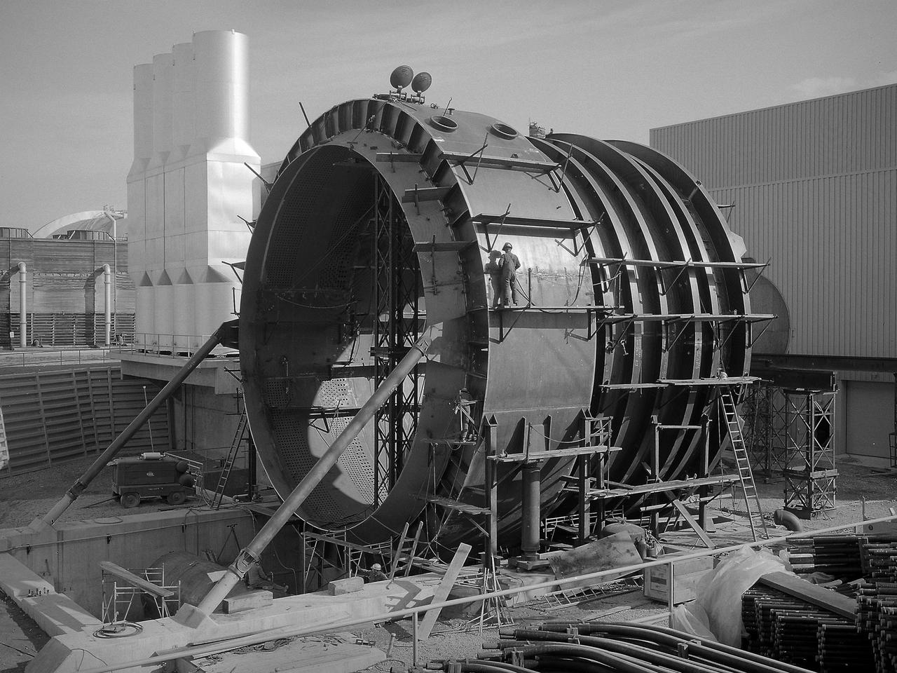
The 50-foot diameter primary cooler for the new Propulsion Systems Laboratory No. 3 and 4 facility constructed at the National Aeronautics and Space Administration (NASA) Lewis Research Center. In 1968, 20 years after planning began for the original Propulsion Systems Laboratory test chambers, No. 1 and 2, NASA Lewis began preparations to add two additional and more powerful chambers. The move coincided with the center’s renewed focus on aeronautics in 1966. The new 40-foot long and 24-foot diameter chambers were capable of testing engines twice as powerful any then in existence and significantly larger than those in the original two test chambers. After exiting the engine nozzle, the hot exhaust air passed through a 17-foot diameter water exhaust duct and the 50-foot diameter primary cooler. Twenty-seven hundred water-filled tubes inside the cooler reduced the temperature of the air flow as it passed between the tubes from 3000 to 600 °F. A spray cooler further reduced the temperature of the gases to 150 °F before they were sent to the Central Air Building. Excavations for the new facility were completed by October 1967, and the shell of the building was completed a year later. In September 1968, work began on the new test chambers and associated infrastructure. Construction was completed in late 1972, and the first test was scheduled for February 1973.
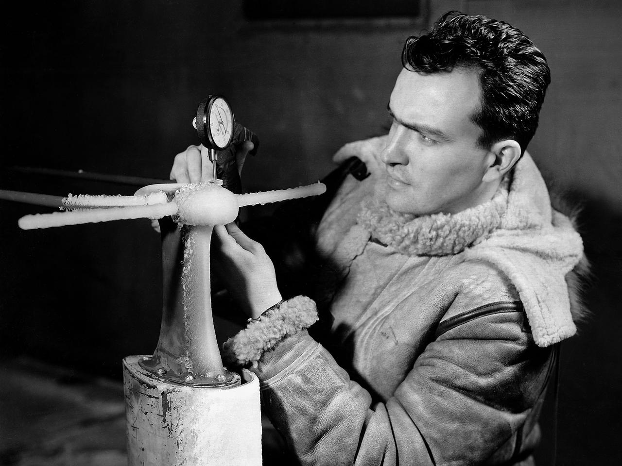
A National Advisory Committee for Aeronautics (NACA) researcher measures the ice thickness on a landing antenna model in the Icing Research Tunnel at the Aircraft Engine Research Laboratory. NACA design engineers added the Icing Research Tunnel to the original layout of the new Aircraft Engine Research Laboratory to take advantage of the massive refrigeration system being built for the Altitude Wind Tunnel. The Icing Research Tunnel was built to study the formation of ice on aircraft surfaces and methods of preventing or eradicating that ice. Ice buildup adds extra weight, effects aerodynamics, and sometimes blocks air flow through engines. The Icing Research Tunnel is a closed-loop atmospheric wind tunnel with a 6- by 9-foot test section. Carrier Corporation refrigeration equipment reduced the internal air temperature to -45 degrees F and a spray bar system injected water droplets into the air stream. The 24-foot diameter drive fan, seen in this photograph, created air flows velocities up to 400 miles per hour. The Icing Research Tunnel began testing in June of 1944. Early testing, seen in this photograph, studied ice accumulation on propellers and antenna of a military aircraft. The Icing Research Tunnel’s designers, however, struggled to develop a realistic spray system since they did not have access to data on the size of naturally occurring water droplets. The system would have to generate small droplets, distribute them uniformly throughout the airstream, and resist freezing and blockage. For five years a variety of different designs were painstakingly developed and tested before the system was perfected.
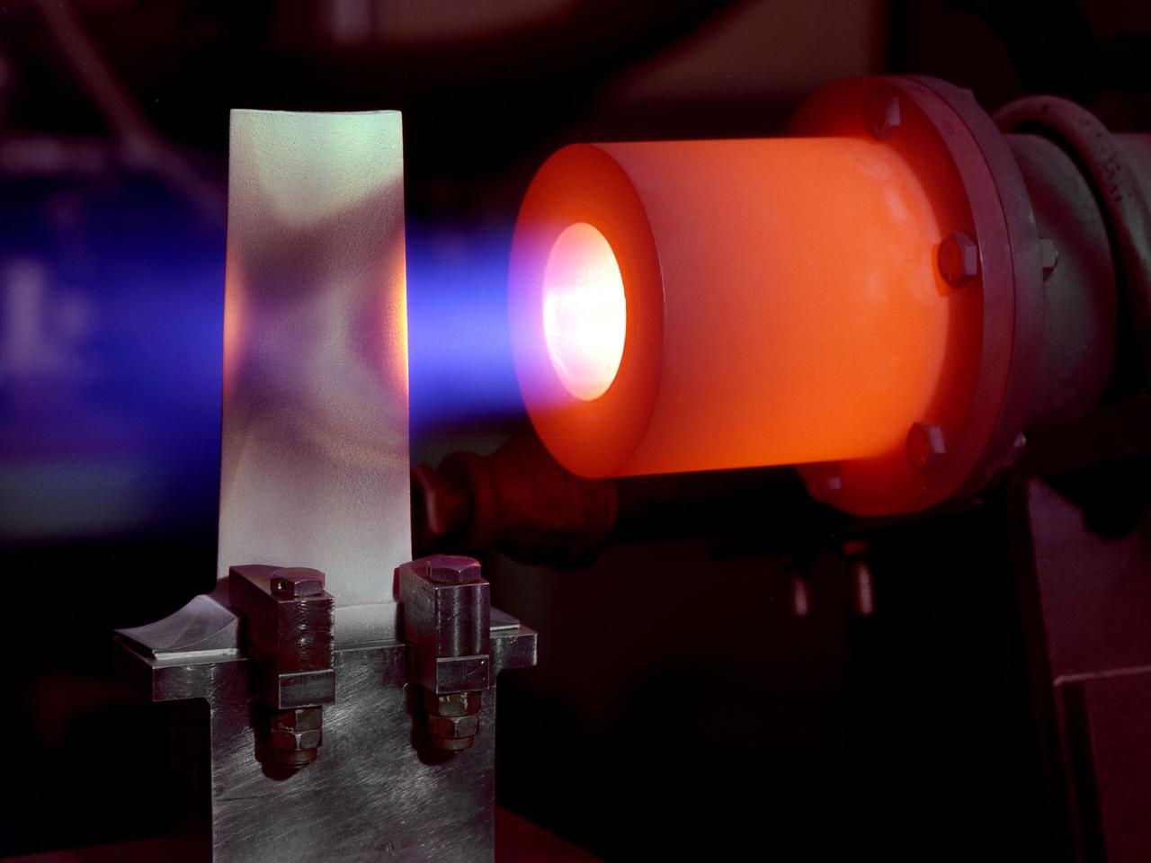
A 1-foot long stator blade with a thermal coating subjected to intense heat in order to test its strength at the National Aeronautics and Space Administration (NASA) Lewis Research Center. Lewis researchers sought to determine optimal types of ceramic coatings to increase the durability of metals. The research was primarily intended to support the design of stator blades for high-performance axial-flow compressor and turbofan engines. The coatings reduced the temperature of the metal and the amount of required cooling. As engines became more and more sophisticated, compressor blades were required to withstand higher and higher temperatures. Lewis researchers developed a dual-layer thermal-barrier coating that could be applied to turbine vanes and blades and combustion liners. This new sprayable thermal-barrier coating was evaluated for its durability, strength, fatigue, and aerodynamic penalties. This hot-gas rig fired the scorching gas at the leading edge of a test blade. The blade was cooled by an internal air flow. The blades were heated at two different velocities during the program. When using Mach 0.3 gases the entire heating and cooling cycle only lasted 30 seconds. The cycle lasted 60 minutes during tests at Mach 1.
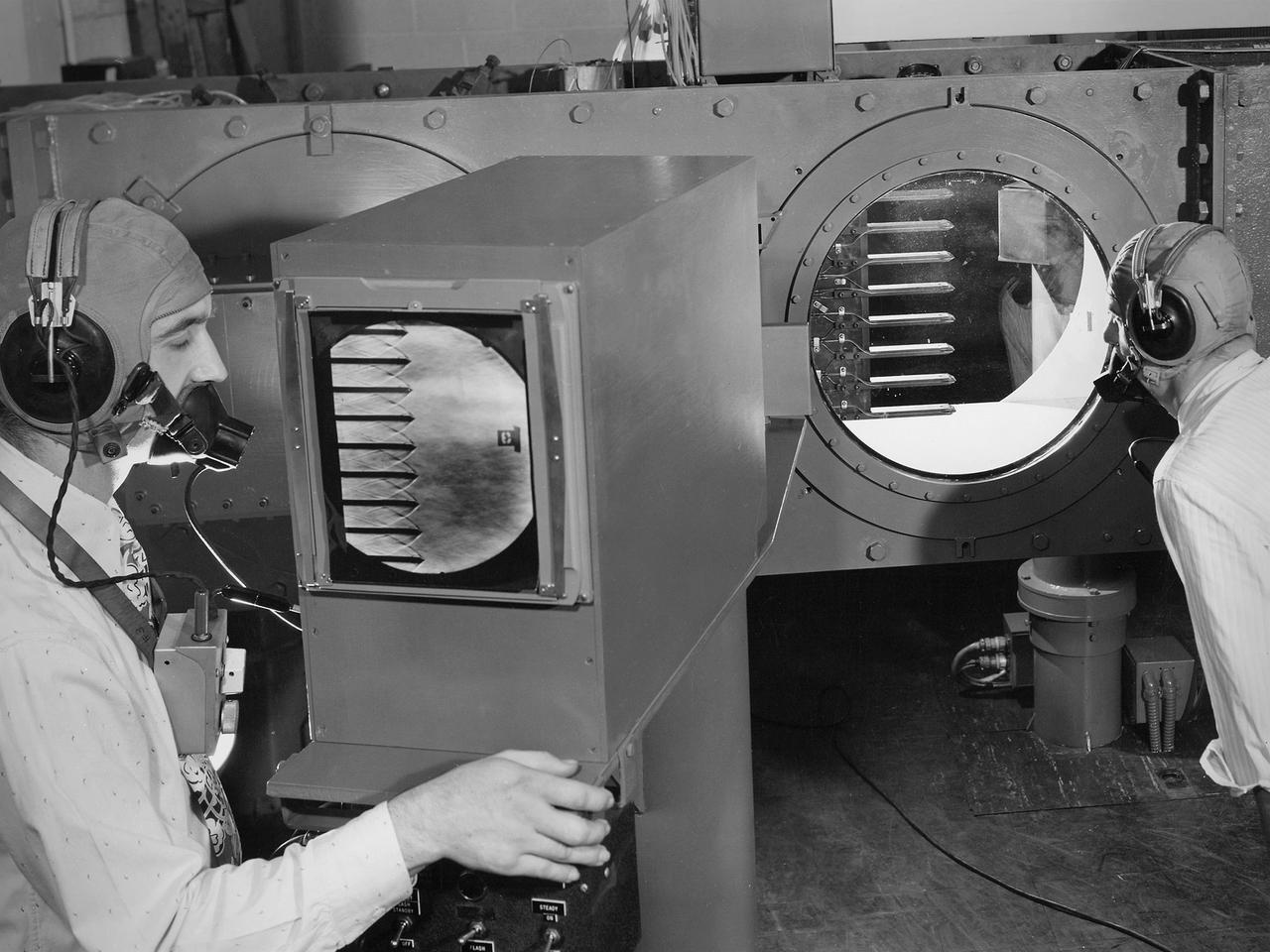
Engineers calibrate one of three small supersonic wind tunnels that were collectively referred to as the “Stack Tunnels” at the National Advisory Committee for Aeronautics (NACA) Lewis Flight Propulsion Laboratory. In late 1945 NACA Lewis reorganized its staff and began constructing a new wave of facilities to address high-speed flight and the turbojet and rocket technologies that emerged during World War II. While design work began on what would eventually become the 8- by 6-Foot Supersonic Wind Tunnel, NACA Lewis quickly built several small supersonic tunnels. These small facilities utilized the Altitude Wind Tunnel’s massive air handling equipment. Three of the small tunnels were built vertically on top of each other and thus were known as the Stack Tunnels. The first of the Stack Tunnels was an 18- by 18-inch tunnel that began operating in August 1945 at speeds up to Mach 1.91. The second tunnel, whose 24- by 24-inch test section is shown here, was added in 1949. It could generate air flows up to Mach 3.96. A third tunnel with an 18- by 18-inch test section began operating in 1951 with speeds up to Mach 3.05. The small tunnels were used until the early 1960s to study the aerodynamic characteristics of supersonic inlets and exits. The technician to the left in this photograph is operating a Schlieren camera to view the air flow dynamics inside the 24- by 24-inch test section. The technician on the right is viewing the pronged test article through the circular window. They are calibrating the tunnel and its equipment to prepare for the initial test runs.
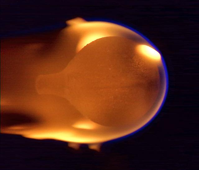
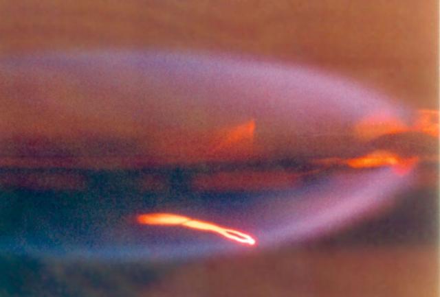
jsc2023e002281 (1/13/2023) --- The Solid Fuel Ignition and Extinction (SoFIE) Growth and Extinction Limits (GEL) experiment successfully conducted its first test in the Combustion Integrated Rack (CIR) aboard the International Space Station (ISS) on January 13th. This image shows a 4-cm diameter sphere of acrylic burning in microgravity. The atmosphere started at 17.5% oxygen in nitrogen and air flow is from right to left at 20 cm/s. The flame appears near the end of the burn, having engulfed the entire sphere after growing from a small ignition point on the right side. Image courtesy of NASA.
A mechanic checks the tubing on one of the many jacks which control the nozzle section of the 10- by 10-Foot Supersonic Wind Tunnel at the National Advisory Committee for Aeronautics (NACA) Lewis Flight Propulsion Laboratory. The 10- by 10-foot tunnel, which had its official opening in May 1956, was built under the Congressional Unitary Plan Act which coordinated wind tunnel construction at the NACA, Air Force, industry, and universities. The 10- by 10 was the largest of the three NACA tunnels built under the act. The 10- by 10 wind tunnel can be operated as a closed circuit for aerodynamic tests or as an open circuit for propulsion investigations. The 10-foot tall and 76-foot long stainless steel nozzle section just upstream from the test section can be adjusted to change the speed and composition of the air flow. Hydraulic jacks, seen in this photograph, flex the 1.37-inch thick walls of the tunnel nozzle. The size of the nozzle’s opening controls the velocity of the air through the test section. Seven General Electric motors capable of generating 25,000 horsepower produce the Mach 2.5 and 2.5 airflows. The facility was mostly operated at night due to its large power load requirements.
The resolution of the Boeing B-29 Superfortress’ engine cooling problems was one of the Aircraft Engine Research Laboratory’s (AERL) key contributions to the World War II effort. The B-29 leapfrogged previous bombers in size, speed, and altitude capabilities. The B–29 was intended to soar above anti-aircraft fire and make pinpoint bomb drops onto strategic targets. Four Wright Aeronautical R-3350 engines powered the massive aircraft. The engines, however, frequently strained and overheated due to payload overloading. This resulted in a growing number of engine fires that often resulted in crashes. The military asked the NACA to tackle the overheating issue. Full-scale engine tests on a R–3350 engine in the Prop House demonstrated that a NACA-designed impeller increased the fuel injection system’s flow rate. Single-cylinder studies resolved a valve failure problem by a slight extension of the cylinder head, and researchers in the Engine Research Building combated uneven heating with a new fuel injection system. Investigations during the summer of 1944 in the Altitude Wind Tunnel, which could simulate flight conditions at high altitudes, led to reduction of drag and improved air flow by reshaping the cowling inlet and outlet. The NACA modifications were then flight tested on a B-29 bomber that was brought to the AERL.
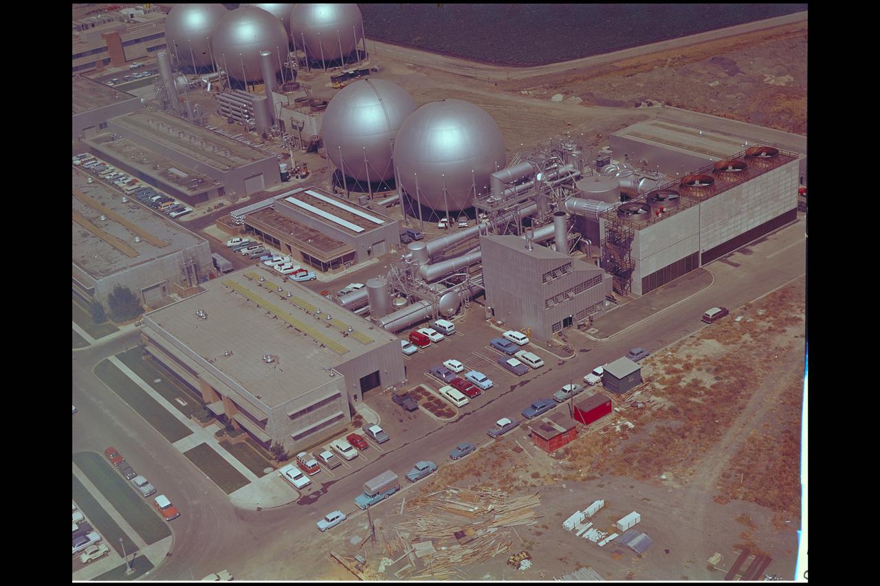
Aerial view of Gasdynamics facility in 1964 and the 20 inch helium tunnel Part of the Thermal Protection Laboratory used to research materials for heat shield applications and for aerodynamic heating and materials studies of vehicles in planetary atmospheres. This laboratory is comprised of five separate facilities: an Aerodynamic Heating Tunnel, a Heat Transfer Tunnel, two Supersonic Turbulent Ducts, and a High-Power CO2 Gasdynamic Laser. All these facilities are driven by arc-heaters, with the exception of the large, combustion-type laser. The arc-heated facilities are powered by a 20 Megawatt DC power supply. Their effluent gas stream (test gases; Air, N2, He, CO2 and mixtures; flow rates from 0.05 to 5.0 lbs/sec) discharges into a five-stage stream-ejector-driven vacuum system. The vacuum system and power supply are common to the test faciities in building N-238. All of the facilities have high pressure water available at flow rates up to 4, 000 gals/min. The data obtained from these facilities are recorded on magnetic tape or oscillographs. All forms of data can be handled whether from thermo-couples, pressure cells, pyrometers, or radiometers, etc. in addition, closed circuit T. V. monitors and various film cameras are available. (operational since 1962)
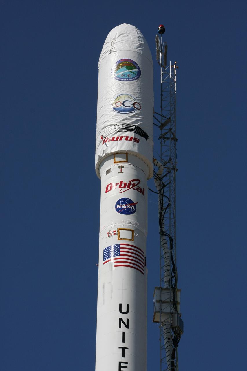
VANDENBERG AIR FORCE BASE, Calif. -- On Launch Complex 576-E at Vandenberg Air Force Base in California, NASA's Orbiting Carbon Observatory, or OCO, spacecraft awaits a GN2 instrument purge flow test in preparation for launch Feb. 24. The spacecraft sits atop Orbital Sciences' Taurus XL rocket. At right is a portion of the umbilical tower attached to the upper stack. The spacecraft sits atop Orbital Sciences' Taurus XL rocket. At right is a portion of the umbilical tower attached to the upper stack. The spacecraft will collect precise global measurements of carbon dioxide (CO2) in the Earth's atmosphere. Scientists will analyze OCO data to improve our understanding of the natural processes and human activities that regulate the abundance and distribution of this important greenhouse gas. Photo courtesy of Jim Stowers, Orbital Sciences
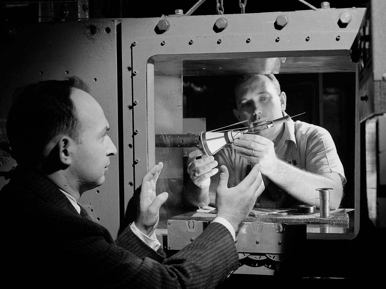
National Aeronautics and Space Administration (NASA) researchers install a small-scale model of the capsule for Project Mercury in the 1- by 1-Foot Supersonic Wind Tunnel at the Lewis Research Center. NASA Lewis conducted a variety of tests for Project Mercury, including retrorocket calibration, escape tower engine performance, and separation of the capsule from simulated Atlas and Redstone boosters. The test of this capsule and escape tower model in the 1- by 1-foot tunnel were run in January and February 1960. The 1-by 1-Foot Supersonic Wind Tunnel had a 15-inch long test section, seen here, that was one foot wide and one foot high. The sides were made of glass to allow cameras to capture the supersonic air flow over the models. The tunnel could generate air flows from Mach 1.3 to 3.0. At the time, it was one of nine small supersonic wind tunnels at Lewis. These tunnels used the exhauster and compressor equipment of the larger facilities. The 1- by 1 tunnel, which began operating in the early 1950s, was built inside a test cell in the expansive Engine Research Building. During the 1950s the 1- by 1 was used to study a variety of inlets, nozzles, and cones for missiles and scramjets. The Mercury capsule tests were among the last at the facility for many years. The tunnel was mothballed in 1960. The 1- by 1 was briefly restored in 1972, then brought back online for good in 1979. The facility has maintained a brisk operating schedule ever since.
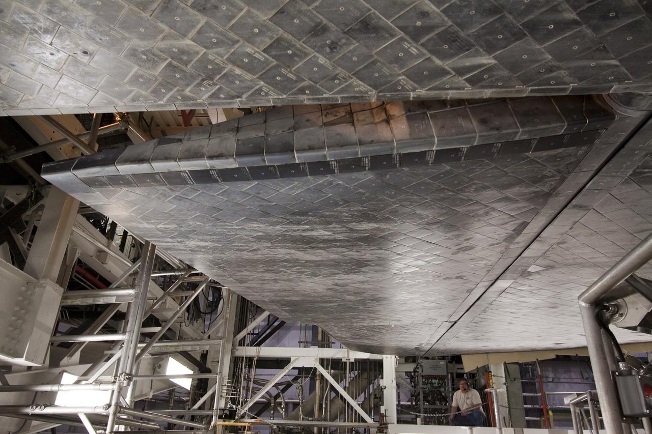
CAPE CANAVERAL, Fla. -- Space shuttle Atlantis goes through a routine landing gear test in Orbiter Processing Facility-1 at NASA's Kennedy Space Center in Florida. Technicians are checking to make sure the shuttle's wheels, brakes, elevons and body flap function properly. Seen here, the body flap is tested. The body flap blocks heat and air flow during the shuttle's re-entry into Earth's atmosphere. Atlantis is being prepared for the STS-135 mission, which will deliver the Raffaello multi-purpose logistics module packed with supplies, logistics and spare parts to the International Space Station. STS-135 is targeted to launch June 28, and will be the last spaceflight for the Space Shuttle Program. Photo credit: NASA/Jack Pfaller

Researcher Susan Johnson and a mechanic examine a flat-plate solar collector in the Solar Simulator Cell in the High Temperature Composites Laboratory at the National Aeronautics and Space Administration (NASA) Lewis Research Center. The Solar Simulator Cell allowed the researchers to control the radiation levels, air temperature, airflow, and fluid flow. The flat-plate collector, seen in a horizontal position here, was directed at the solar simulator, seen above Johnson, during the tests. Lewis researchers were studying the efficiency of various flat- plate solar collector designs in the 1970s for temperature control systems in buildings. The collectors consisted of a cover material, absorber plate, and parallel flow configuration. The collector’s absorber material and coating, covers, honeycomb material, mirrors, vacuum, and tube attachment could all be modified. Johnson’s study analyzed 35 collectors. Johnson, a lifelong pilot, joined NASA Lewis in 1974. The flat-plate solar collectors, seen here, were her first research project. Johnson also investigated advanced heat engines for general aviation and evaluated variable geometry combustors and liners. Johnson earned the Cleveland Technical Society’s Technical Achievement Award in 1984.

Technicians set up test hardware inside the test section of the Icing Research Tunnel at the National Aeronautics and Space Administration (NASA) Lewis Research Center. The Icing Research Tunnel was built in the early 1940s to study the formation of ice on aircraft surfaces and develop methods of preventing or eradicating that ice. Ice buildup is dangerous because it adds extra weight, effects aerodynamics, and sometimes blocks air flow through engines. The Icing Research Tunnel is a closed-loop atmospheric wind tunnel with a 6- by 9-foot test section. The tunnel can produce speeds up to 300 miles per hour and temperatures from 30 to -45 °F. NACA engineers struggled initially to perfect a spray bar system to introduce moisture into the airstream. The tunnel was shut down in the late 1950s as the center focused its energy exclusively on space. Industrial customers began using the tunnel sporadically, then steadily, in the 1960s. Boeing, Aerojet, Lockheed, Sikorsky, Beech and others ran tests during the 1960s. Boeing analyzed engine inlets for the CH-47 Chinook, CH-46 (Sea Knight) and CH-113. This photograph was taken during a series of 100 ice-phobic coatings for the Federal Aviation Administration. They found that many of the coatings reduced ice adhesion to the test sample, but they could not be used for aircraft applications.
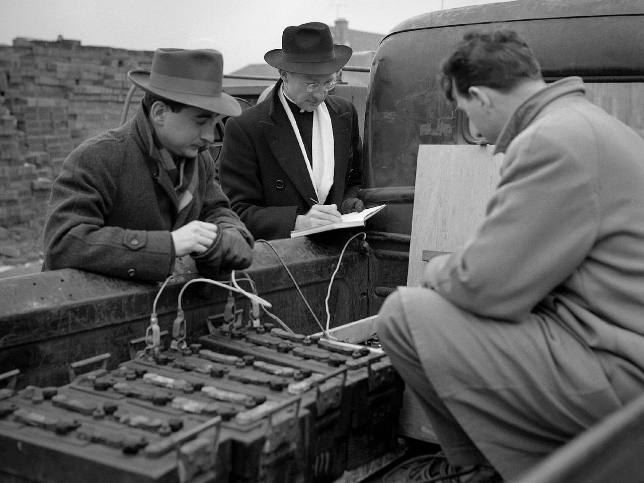
Reverend Henry Birkenhauer and E.F. Carome measure ground vibrations on West 220th Street caused by the operation of the 8- by 6-Foot Supersonic Wind Tunnel at the National Advisory Committee for Aeronautics (NACA) Lewis Flight Propulsion Laboratory. The 8- by 6 was the laboratory’s first large supersonic wind tunnel. It was also the NACA’s most powerful supersonic tunnel, and the NACA’s first facility capable of running an engine at supersonic speeds. The 8- by 6 was originally an open-throat and non-return tunnel. This meant that the supersonic air flow was blown through the test section and out the other end into the atmosphere. Complaints from the local community led to the installation of a muffler at the tunnel exit and the eventual addition of a return leg. Reverend Brikenhauer, a seismologist, and Carome, an electrical technician were brought in from John Carroll University to take vibration measurements during the 8- by 6 tunnel’s first run with a supersonic engine. They found that the majority of the vibrations came from the air and not the ground. The tunnel’s original muffler offered some relief during the facility checkout runs, but it proved inadequate during the operation of an engine in the test section. Tunnel operation was suspended until a new muffler was designed and installed. The NACA researchers, however, were pleased with the tunnel’s operation. They claimed it was the first time a jet engine was operated in an airflow faster than Mach 2.
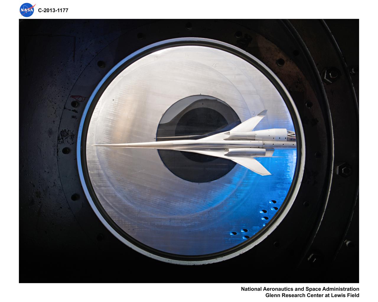
Supersonic Aircraft Model The window in the sidewall of the 8- by 6-foot supersonic wind tunnel at NASA's Glenn Research Center shows a 1.79 percent scale model of a future concept supersonic aircraft built by The Boeing Company. In recent tests, researchers evaluated the performance of air inlets mounted on top of the model to see how changing the amount of airflow at supersonic speeds through the inlet affected performance. The inlet on the pilot's right side (top inlet in this side view) is larger because it contains a remote-controlled device through which the flow of air could be changed. The work is part of ongoing research in NASA's Aeronautics Research Mission Directorate to address the challenges of making future supersonic flight over land possible. Researchers are testing overall vehicle design and performance options to reduce emissions and noise, and identifying whether the volume of sonic booms can be reduced to a level that leads to a reversal of the current ruling that prohibits commercial supersonic flight over land. Image Credit: NASA/Quentin Schwinn
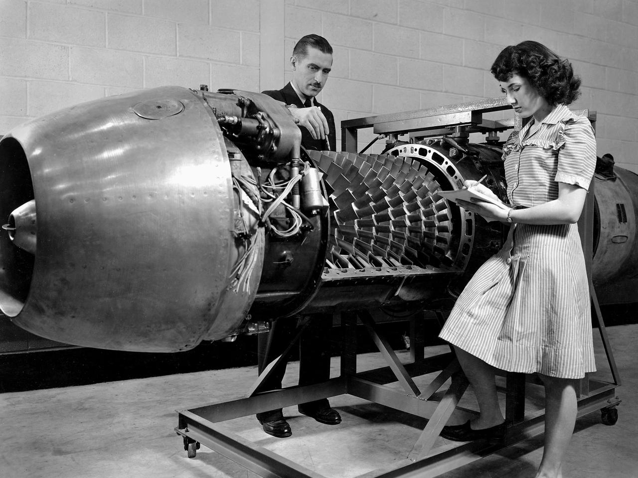
Researcher Robert Miller led an investigation into the combustor performance of a German Jumo 004 engine at the National Advisory Committee for Aeronautics (NACA) Lewis Flight Propulsion Laboratory. The Jumo 004 powered the world's first operational jet fighter, the Messerschmitt Me 262, beginning in 1942. The Me 262 was the only jet aircraft used in combat during World War II. The eight-stage axial-flow compressor Jumo 004 produced 2000 pounds of thrust. The US Army Air Forces provided the NACA with a Jumo 004 engine in 1945 to study the compressor’s design and performance. Conveniently the engine’s designer Anselm Franz had recently arrived at Wright-Patterson Air Force Base in nearby Dayton, Ohio as part of Project Paperclip. The Lewis researchers used a test rig in the Engine Research Building to analyze one of the six combustion chambers. It was difficult to isolate a single combustor’s performance when testing an entire engine. The combustion efficiency, outlet-temperature distribution, and total pressure drop were measured. The researchers determined the Jumo 004’s maximum performance was 5000 revolutions per minute at a 27,000 foot altitude and 11,000 revolutions per minute at a 45,000 foot altitude. The setup in this photograph was created for a tour of NACA Lewis by members of the Institute of Aeronautical Science on March 22, 1945.
Supersonic Aircraft Model The window in the sidewall of the 8- by 6-foot supersonic wind tunnel at NASA's Glenn Research Center shows a 1.79 percent scale model of a future concept supersonic aircraft built by The Boeing Company. In recent tests, researchers evaluated the performance of air inlets mounted on top of the model to see how changing the amount of airflow at supersonic speeds through the inlet affected performance. The inlet on the pilot's right side (top inlet in this side view) is larger because it contains a remote-controlled device through which the flow of air could be changed. The work is part of ongoing research in NASA's Aeronautics Research Mission Directorate to address the challenges of making future supersonic flight over land possible. Researchers are testing overall vehicle design and performance options to reduce emissions and noise, and identifying whether the volume of sonic booms can be reduced to a level that leads to a reversal of the current ruling that prohibits commercial supersonic flight over land. Image Credit: NASA/Quentin Schwinn
A technician checks a 0.25-scale engine model of a Vought Corporation V-530 engine in the test section of the 10- by 10-Foot Supersonic Wind Tunnel at the National Aeronautics and Space Administration (NASA) Lewis Research Center. Vought created a low-drag tandem-fan Vertical/Short and Takeoff and Landing (V/STOL) engine in the mid-1970s, designated as the V-530. The first fan on the tandem-fan engine was supplied with air through a traditional subsonic inlet, seen on the lower front of the engine. The air was exhausted through the nacelle during normal flight and directed down during takeoffs. The rear fan was supplied by the oval-shaped top inlet during all phases of the flight. The second fan exhausted its air through a rear vectorable nozzle. NASA Lewis and Vought partnered in the late 1970s to collect an array of inlet and nozzle design information on the tandem fan engines for the Navy. Vought created this .25-scale model of the V-530 for extensive testing in Lewis' 10- by 10-foot tunnel. During an early series of tests, the front fan was covered, and a turbofan simulator was used to supply air to the rear fan. The researchers then analyzed the performance of only the front fan inlet. During the final series of tests, the flow from the front fan was used to supply airflow to the rear fan. The researchers studied the inlet's recovery, distortion, and angle-of-attack limits over various flight conditions.
CAPE CANAVERAL, Fla. -- At NASA's Kennedy Space Center in Florida, testing of the Tilt-Up Umbilical Arm (TUUA) prototype's Environmental Control System Quick Disconnect takes place in the Launch Equipment Test Facility's 6,000-square-foot high bay. The prototype is used to demonstrate the safe disconnect and retraction of ground umbilical plates and associated hardware of a launch vehicle's upper stage and service module. The Environmental Control System consists of regulated air, which would be used to purge an inner tank and crew module. Since 1977, the facility has supported NASA’s Launch Services, shuttle, International Space Station, and Constellation programs, as well as commercial providers. The facility recently underwent a major upgrade to support even more programs, projects and customers. It houses a cable fabrication and molding shop, pneumatics shop, machine and weld shop and full-scale control room. Outside, the facility features a water flow test loop, vehicle motion simulator, 600-ton test fixture, launch simulation towers and a cryogenic system. Photo credit: NASA/Jack Pfaller
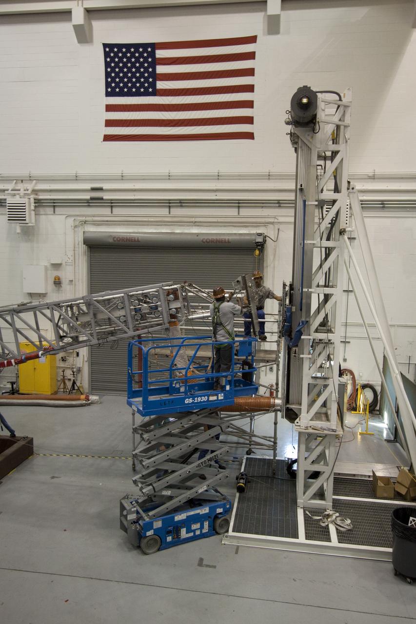
CAPE CANAVERAL, Fla. -- At NASA's Kennedy Space Center in Florida, testing of the Tilt-Up Umbilical Arm (TUUA) prototype's Environmental Control System Quick Disconnect takes place in the Launch Equipment Test Facility's 6,000-square-foot high bay. The prototype is used to demonstrate the safe disconnect and retraction of ground umbilical plates and associated hardware of a launch vehicle's upper stage and service module. The Environmental Control System consists of regulated air, which would be used to purge an inner tank and crew module. Since 1977, the facility has supported NASA’s Launch Services, shuttle, International Space Station, and Constellation programs, as well as commercial providers. The facility recently underwent a major upgrade to support even more programs, projects and customers. It houses a cable fabrication and molding shop, pneumatics shop, machine and weld shop and full-scale control room. Outside, the facility features a water flow test loop, vehicle motion simulator, 600-ton test fixture, launch simulation towers and a cryogenic system. Photo credit: NASA/Jack Pfaller
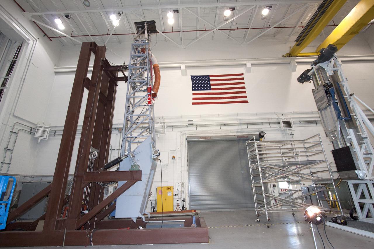
CAPE CANAVERAL, Fla. -- At NASA's Kennedy Space Center in Florida, testing of the Tilt-Up Umbilical Arm (TUUA) prototype's Environmental Control System Quick Disconnect takes place in the Launch Equipment Test Facility's 6,000-square-foot high bay. The prototype is used to demonstrate the safe disconnect and retraction of ground umbilical plates and associated hardware of a launch vehicle's upper stage and service module. The Environmental Control System consists of regulated air, which would be used to purge an inner tank and crew module. Since 1977, the facility has supported NASA’s Launch Services, shuttle, International Space Station, and Constellation programs, as well as commercial providers. The facility recently underwent a major upgrade to support even more programs, projects and customers. It houses a cable fabrication and molding shop, pneumatics shop, machine and weld shop and full-scale control room. Outside, the facility features a water flow test loop, vehicle motion simulator, 600-ton test fixture, launch simulation towers and a cryogenic system. Photo credit: NASA/Jack Pfaller
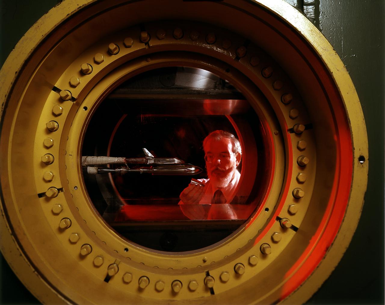
An engineer at the Marshall Space Flight Center (MSFC) observes a model of the Space Shuttle Orbiter being tested in the MSFC's 14x14-Inch Trisonic Wind Tunnel. The 14-Inch Wind Tunnel is a trisonic wind tunnel. This means it is capable of running subsonic, below the speed of sound; transonic, at or near the speed of sound (Mach 1,760 miles per hour at sea level); or supersonic, greater than Mach 1 up to Mach 5. It is an intermittent blowdown tunnel that operates by high pressure air flowing from storage to either vacuum or atmospheric conditions. The MSFC 14x14-Inch Trisonic Wind Tunnel has been an integral part of the development of the United States space program Rocket and launch vehicles from the Jupiter-C in 1958, through the Saturn family up to the current Space Shuttle and beyond have been tested in this Wind Tunnel. MSFC's 14x14-Inch Trisonic Wind Tunnel, as with most other wind tunnels, is named after the size of the test section. The 14-Inch Wind Tunnel, as in the past, will continue to play a large but unseen role in the development of America's space program.
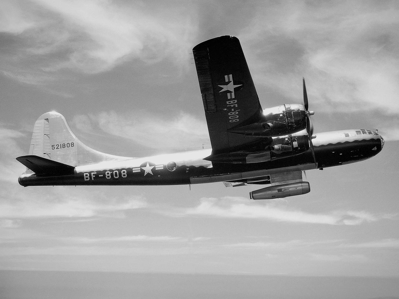
The NACA’s Lewis Flight Propulsion Laboratory used a Boeing B‒29 Superfortress as a testbed for ramjet investigations in the late 1940s. Lewis researchers conducted a wide variety of studies on ramjets to determine basic the operational data necessary to design missiles. Extensive wind tunnel and test stand studies were augmented by actual flight tests. Lewis engineers modified this B‒29 so that the ramjet could be stored in the bomb bay. Once the aircraft reached the desired altitude and speed, a mechanical arm suspended the ramjet 52 inches below the bomb bay. The ramjet’s angle-of-attack could be independently adjusted, and a periscope permitted a view of the test article from inside the aircraft. Researchers took measurements in free-stream conditions at speeds up to Mach 0.51 and at altitudes ranging from 5,000 to 30,000 feet. They then shut the ramjet down and retracted it into the aircraft. The researchers first determined that 14,000 feet was the maximum altitude at which the engine could be ignited by spark. They used flares to start the engine at altitudes up to 30,000 feet. They were able to determine maximum combustion efficiencies, response time to changes in fuel flow, and minimum fuel-air ratios. Overall the ramjet operated well at all speeds and altitudes.
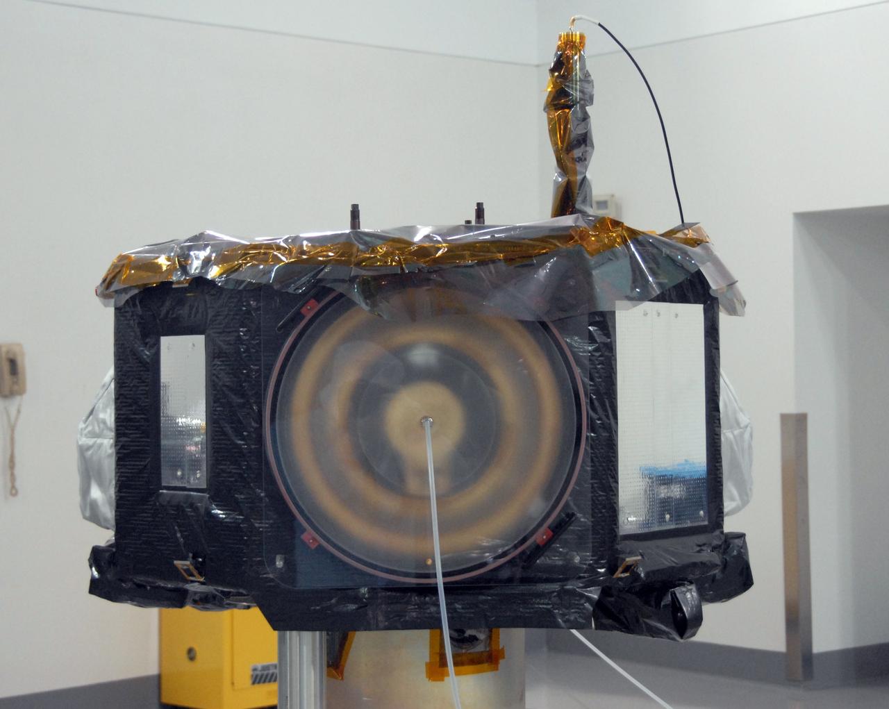
VANDENBERG AIR FORCE BASE, Calif. - At Vandenberg Air Force Base in California, the NASA's Interstellar Boundary Explorer, or IBEX, spacecraft seen here is being prepared for a spin balance test. The IBEX satellite will make the first map of the boundary between the Solar System and interstellar space. IBEX is the first mission designed to detect the edge of the Solar System. As the solar wind from the sun flows out beyond Pluto, it collides with the material between the stars, forming a shock front. IBEX contains two neutral atom imagers designed to detect particles from the termination shock at the boundary between the Solar System and interstellar space. IBEX also will study galactic cosmic rays, energetic particles from beyond the Solar System that pose a health and safety hazard for humans exploring beyond Earth orbit. IBEX will make these observations from a highly elliptical orbit that takes it beyond the interference of the Earth's magnetosphere. IBEX is targeted for launch from a Pegasus XL rocket on Oct. 5. Photo credit: NASA/VAFB
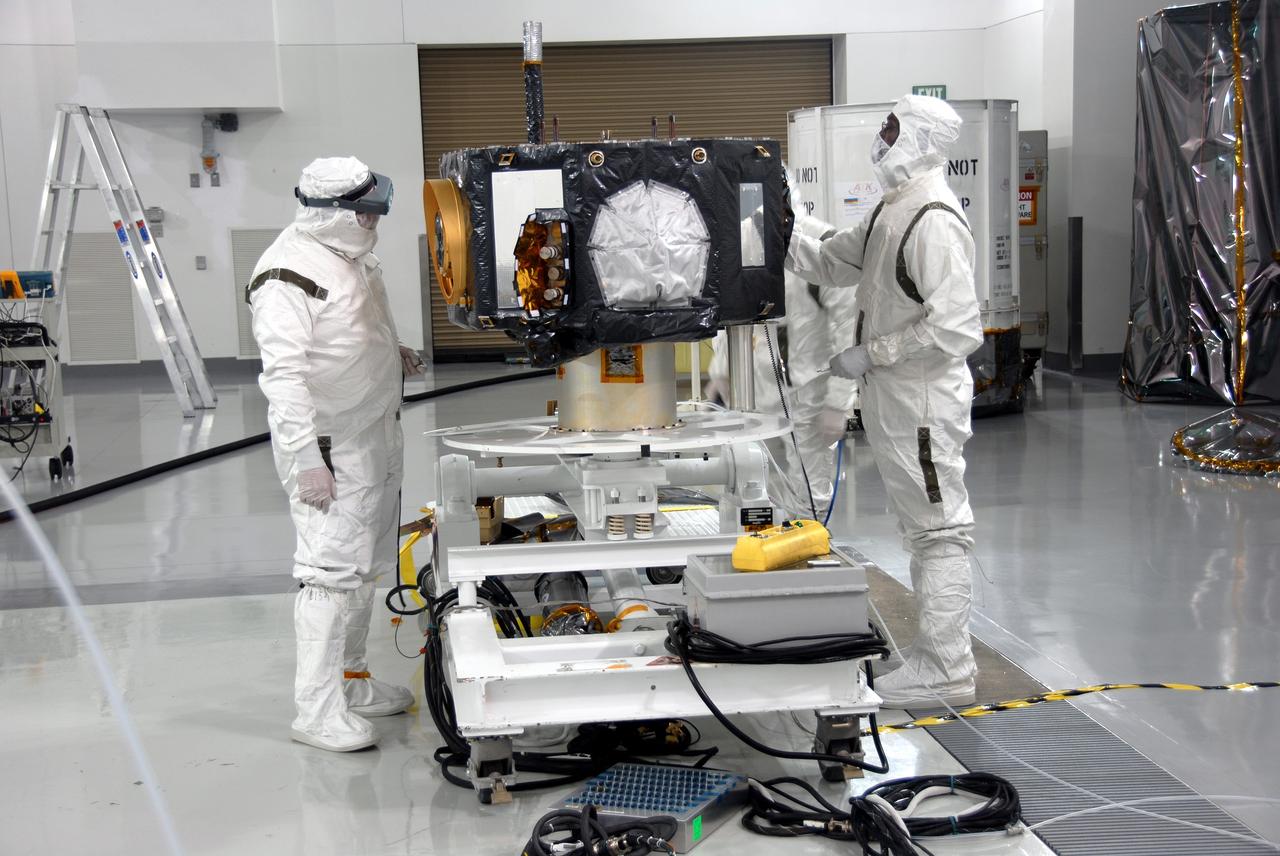
VANDENBERG AIR FORCE BASE, Calif. - At Vandenberg Air Force Base in California, NASA's Interstellar Boundary Explorer, or IBEX, spacecraft is ready for spin balance testing. The IBEX satellite will make the first map of the boundary between the Solar System and interstellar space. IBEX is the first mission designed to detect the edge of the Solar System. As the solar wind from the sun flows out beyond Pluto, it collides with the material between the stars, forming a shock front. IBEX contains two neutral atom imagers designed to detect particles from the termination shock at the boundary between the Solar System and interstellar space. IBEX also will study galactic cosmic rays, energetic particles from beyond the Solar System that pose a health and safety hazard for humans exploring beyond Earth orbit. IBEX will make these observations from a highly elliptical orbit that takes it beyond the interference of the Earth's magnetosphere. IBEX is targeted for launch from a Pegasus XL rocket on Oct. 5. Photo credit: NASA/VAFB
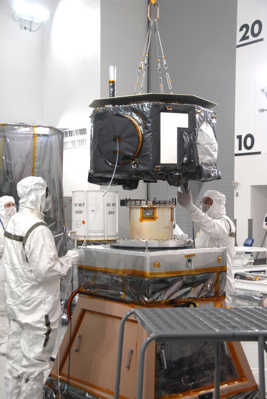
VANDENBERG AIR FORCE BASE, Calif. - At Vandenberg Air Force Base in California, a technician helps guide the placement of NASA's Interstellar Boundary Explorer, or IBEX, spacecraft onto a stand for spin balance testing. The IBEX satellite will make the first map of the boundary between the Solar System and interstellar space. IBEX is the first mission designed to detect the edge of the Solar System. As the solar wind from the sun flows out beyond Pluto, it collides with the material between the stars, forming a shock front. IBEX contains two neutral atom imagers designed to detect particles from the termination shock at the boundary between the Solar System and interstellar space. IBEX also will study galactic cosmic rays, energetic particles from beyond the Solar System that pose a health and safety hazard for humans exploring beyond Earth orbit. IBEX will make these observations from a highly elliptical orbit that takes it beyond the interference of the Earth's magnetosphere. IBEX is targeted for launch from a Pegasus XL rocket on Oct. 5. Photo credit: NASA/VAFB
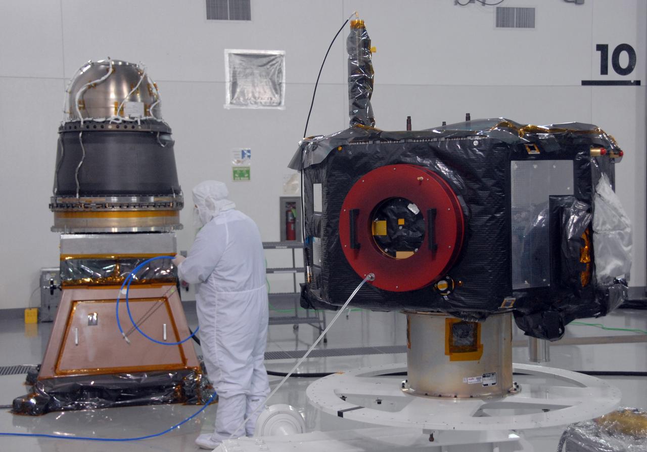
VANDENBERG AIR FORCE BASE, Calif. – At Vandenberg Air Force Base in California, at right is the NASA's Interstellar Boundary Explorer, or IBEX, spacecraft. At left are the Star-27 kick motor and nozzle for IBEX “on top” and the adapter cone, part of the IBEX flight system, underneath. The IBEX is being prepared for a spin balance test. The IBEX satellite will make the first map of the boundary between the Solar System and interstellar space. IBEX is the first mission designed to detect the edge of the Solar System. As the solar wind from the sun flows out beyond Pluto, it collides with the material between the stars, forming a shock front. IBEX contains two neutral atom imagers designed to detect particles from the termination shock at the boundary between the Solar System and interstellar space. IBEX also will study galactic cosmic rays, energetic particles from beyond the Solar System that pose a health and safety hazard for humans exploring beyond Earth orbit. IBEX will make these observations from a highly elliptical orbit that takes it beyond the interference of the Earth's magnetosphere. IBEX is targeted for launch from a Pegasus XL rocket on Oct. 5. Photo credit: NASA/VAFB
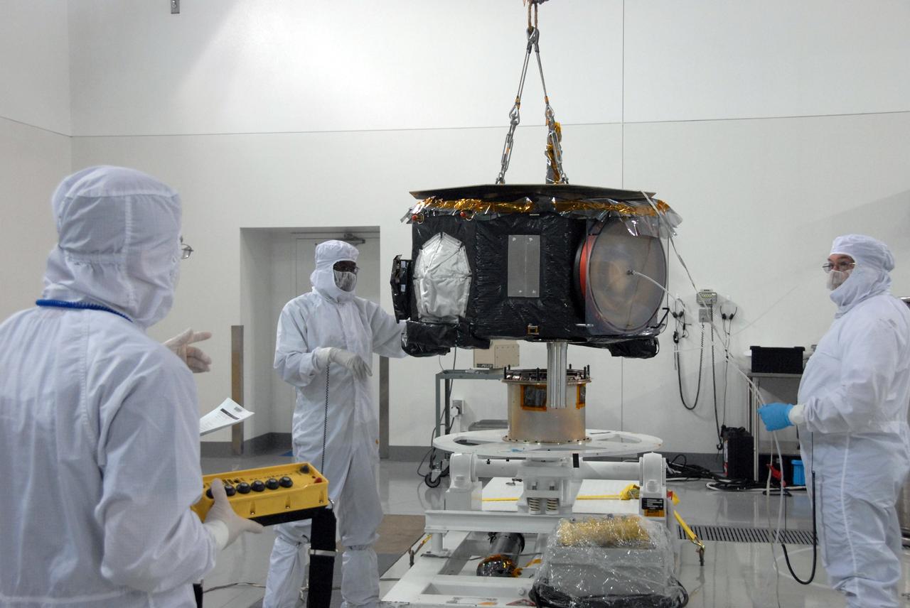
VANDENBERG AIR FORCE BASE, Calif. - At Vandenberg Air Force Base in California, the NASA's Interstellar Boundary Explorer, or IBEX, spacecraft is lifted toward a spin stand (behind it) for testing. The IBEX satellite will make the first map of the boundary between the Solar System and interstellar space. IBEX is the first mission designed to detect the edge of the Solar System. As the solar wind from the sun flows out beyond Pluto, it collides with the material between the stars, forming a shock front. IBEX contains two neutral atom imagers designed to detect particles from the termination shock at the boundary between the Solar System and interstellar space. IBEX also will study galactic cosmic rays, energetic particles from beyond the Solar System that pose a health and safety hazard for humans exploring beyond Earth orbit. IBEX will make these observations from a highly elliptical orbit that takes it beyond the interference of the Earth's magnetosphere. IBEX is targeted for launch from a Pegasus XL rocket on Oct. 5. Photo credit: NASA/VAFB