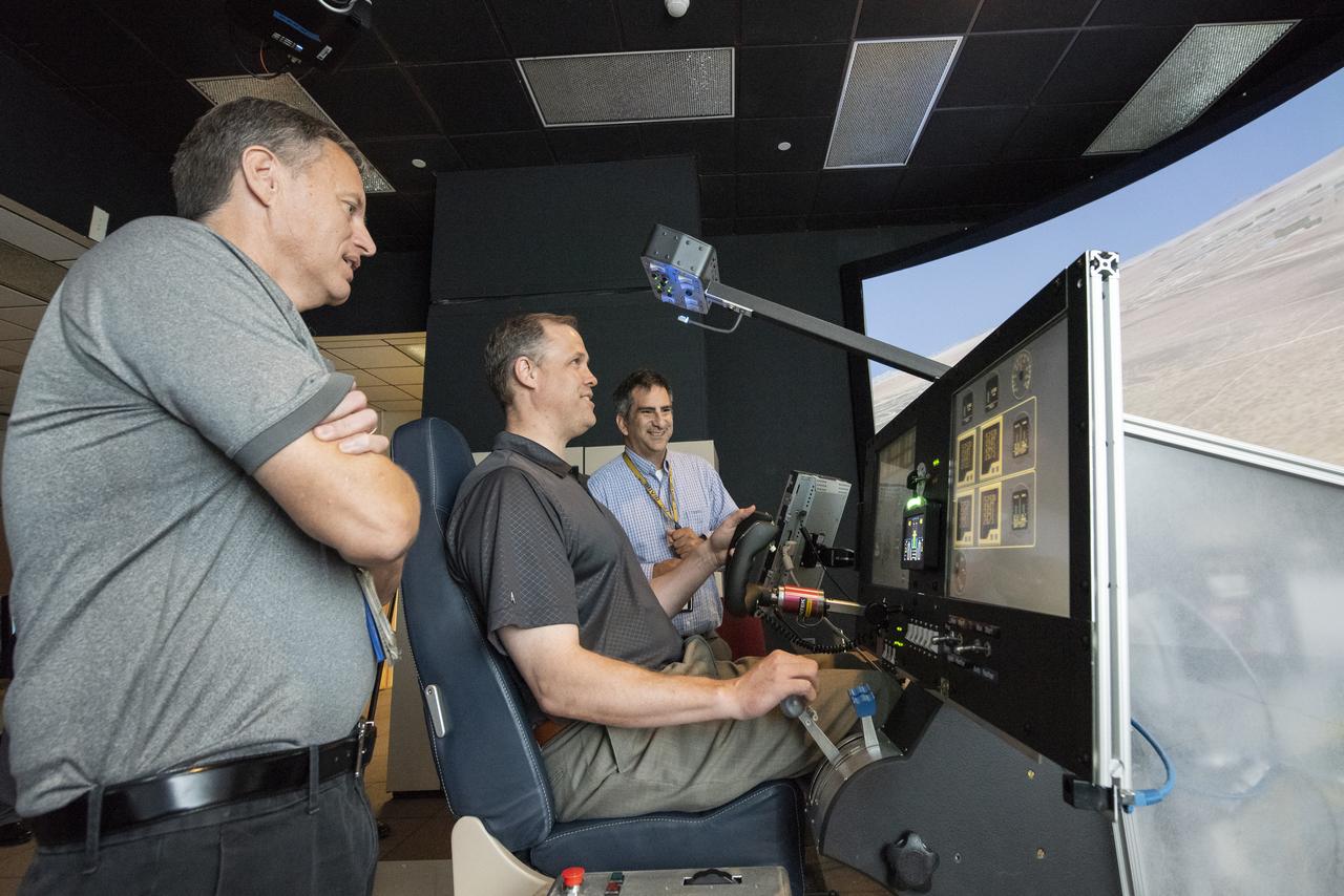
NASA Administrator Bridenstine tests the X-57 "Maxwell" simulator at NASA's Armstrong Flight Research Center. The simulator is designed to provide feedback to NASA test pilots based on the aircraft's unique design and distributed electric propulsion system.
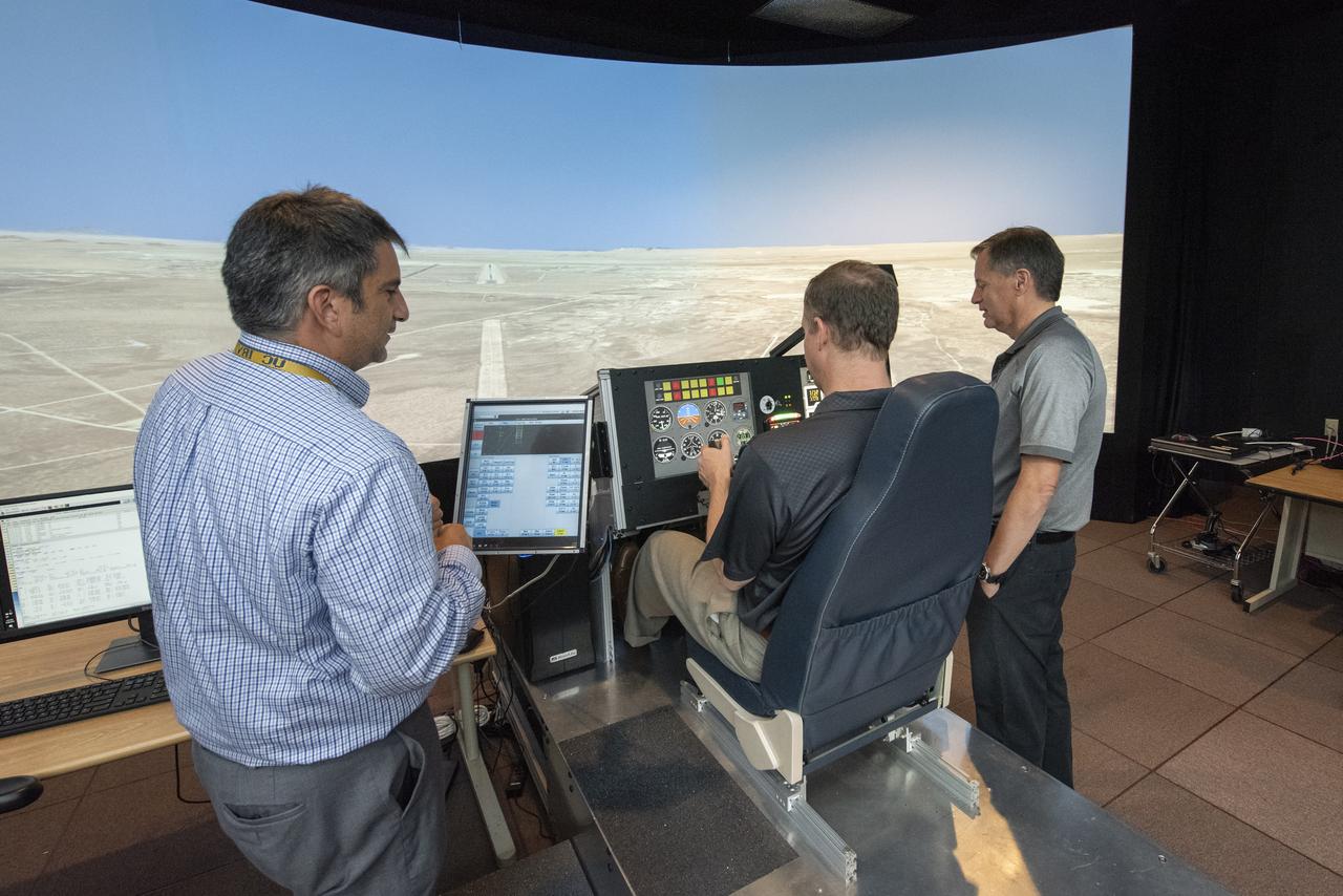
NASA Administrator Bridenstine tests the X-57 "Maxwell" simulator at NASA's Armstrong Flight Research Center. The simulator is designed to provide feedback to NASA test pilots based on the aircraft's unique design and distributed electric propulsion system.
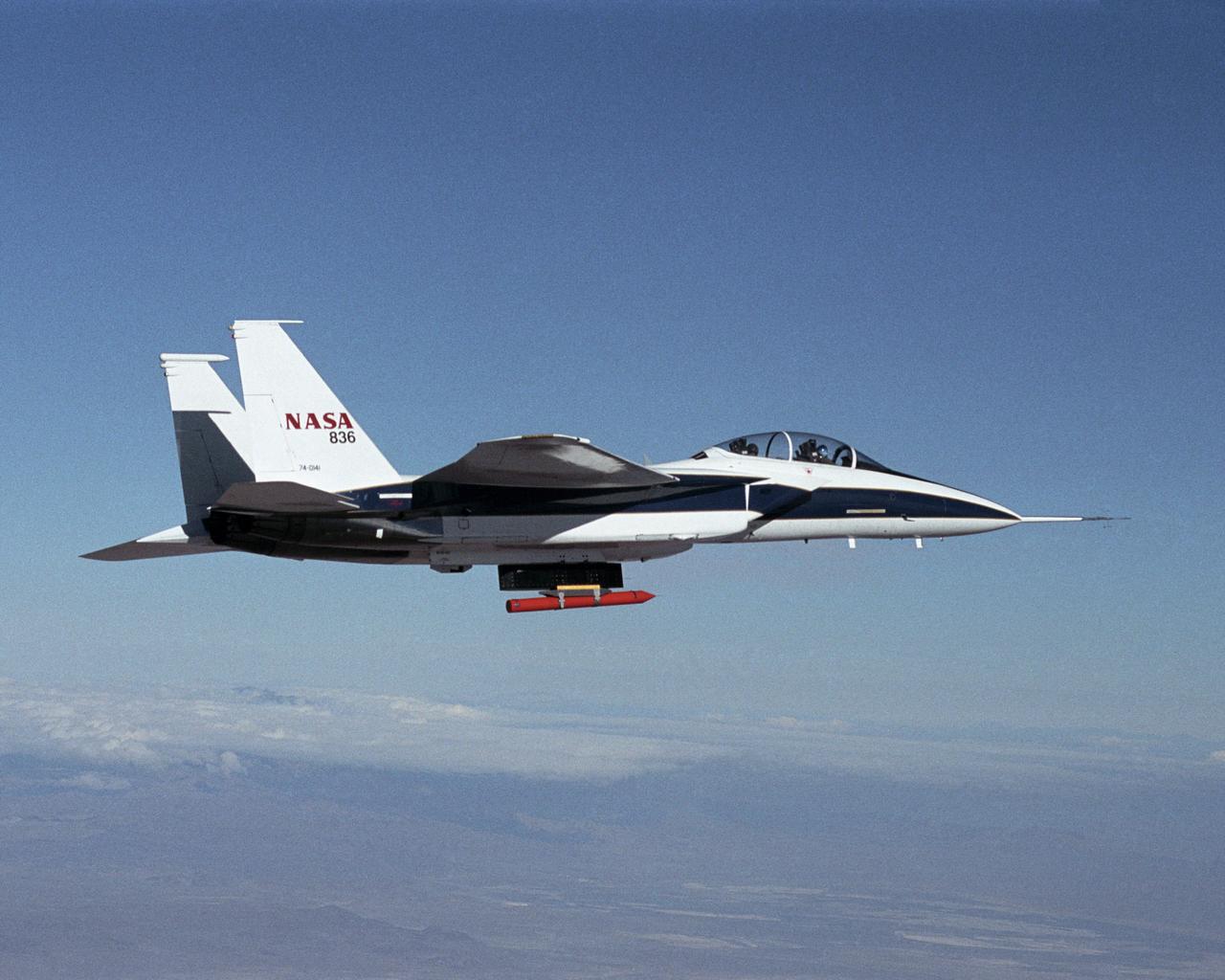
NASA Dryden's new in-house designed Propulsion Flight Test Fixture (PFTF) flew mated to a specially-equipped supersonic F-15B research aircraft during December 2001 and January 2002.
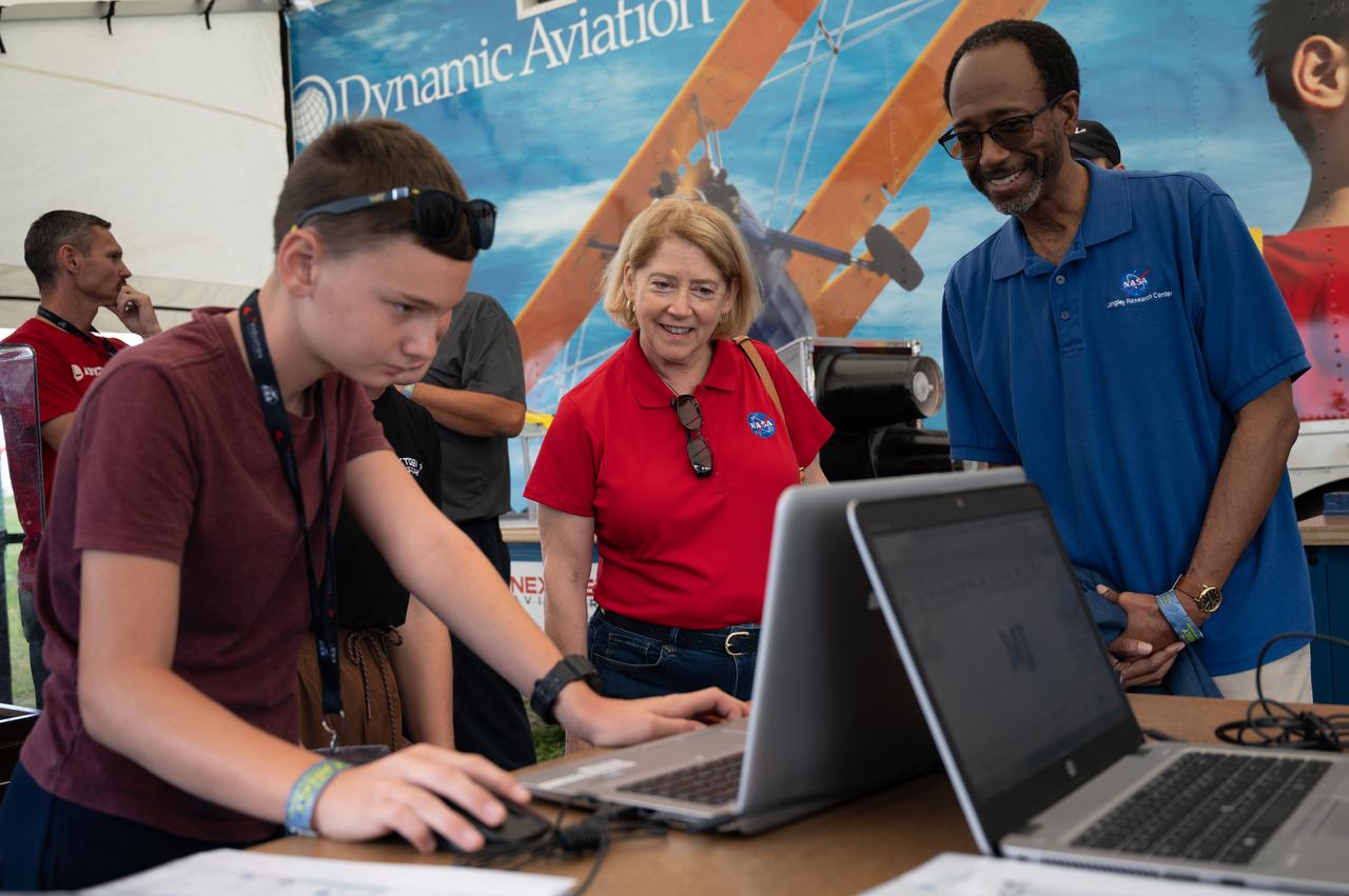
Silas Webb explains his CAD aircraft design to Deputy Administrator Pam Melroy and Langley Director Clayton Turner on Thursday, July 28, 2022, at the NEXTGEN Aviators exhibit at AirVenture Oshkosh.
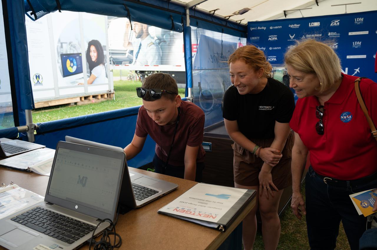
Deputy Administrator Pam Melroy tours the NEXTGEN Aviators exhibit on Thursday, July 28, 2022, at EAA AirVenture. Here Silas Webb explains his CAD aircraft design with the help of Kala Dougan.
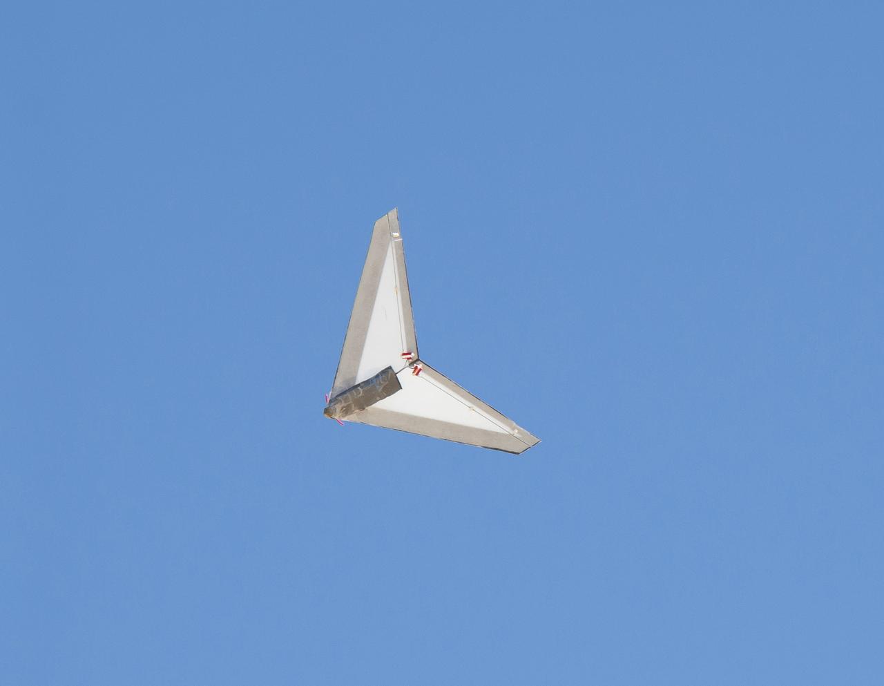
The Preliminary Research Aerodynamic Design to Land on Mars, or Prandtl-M, flies during a test flight. A new proposal based on the aircraft recently won an agencywide technology grant.
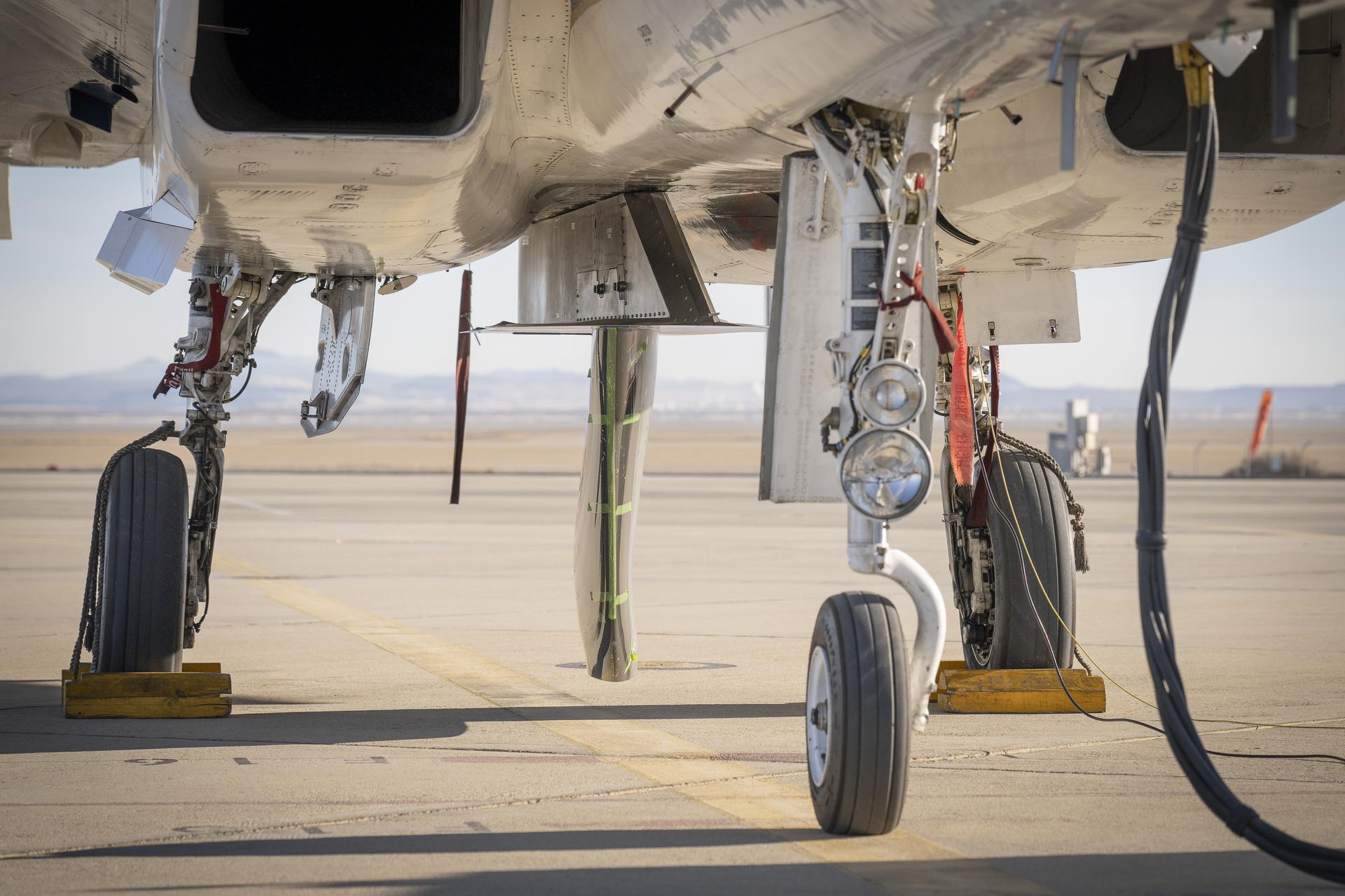
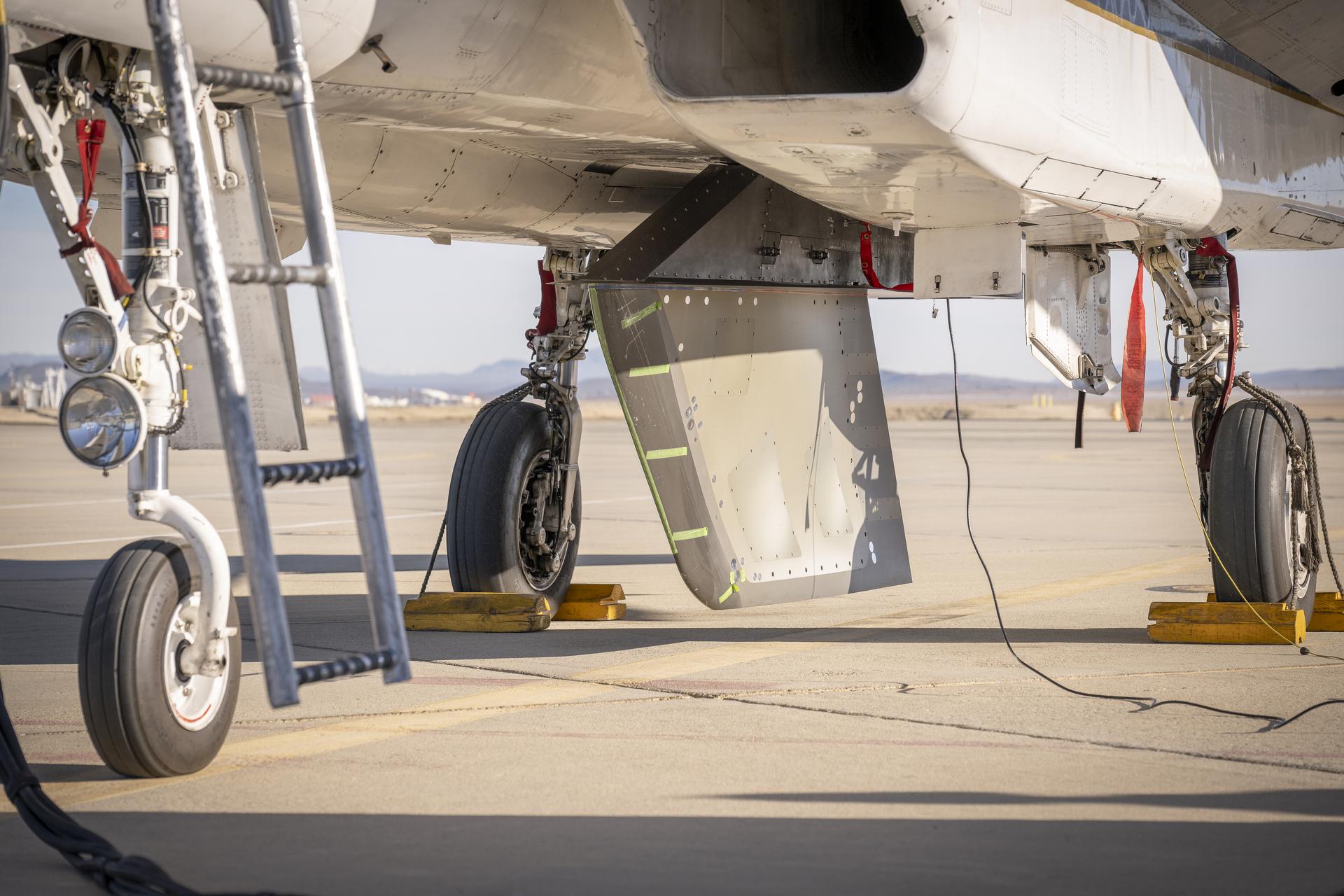
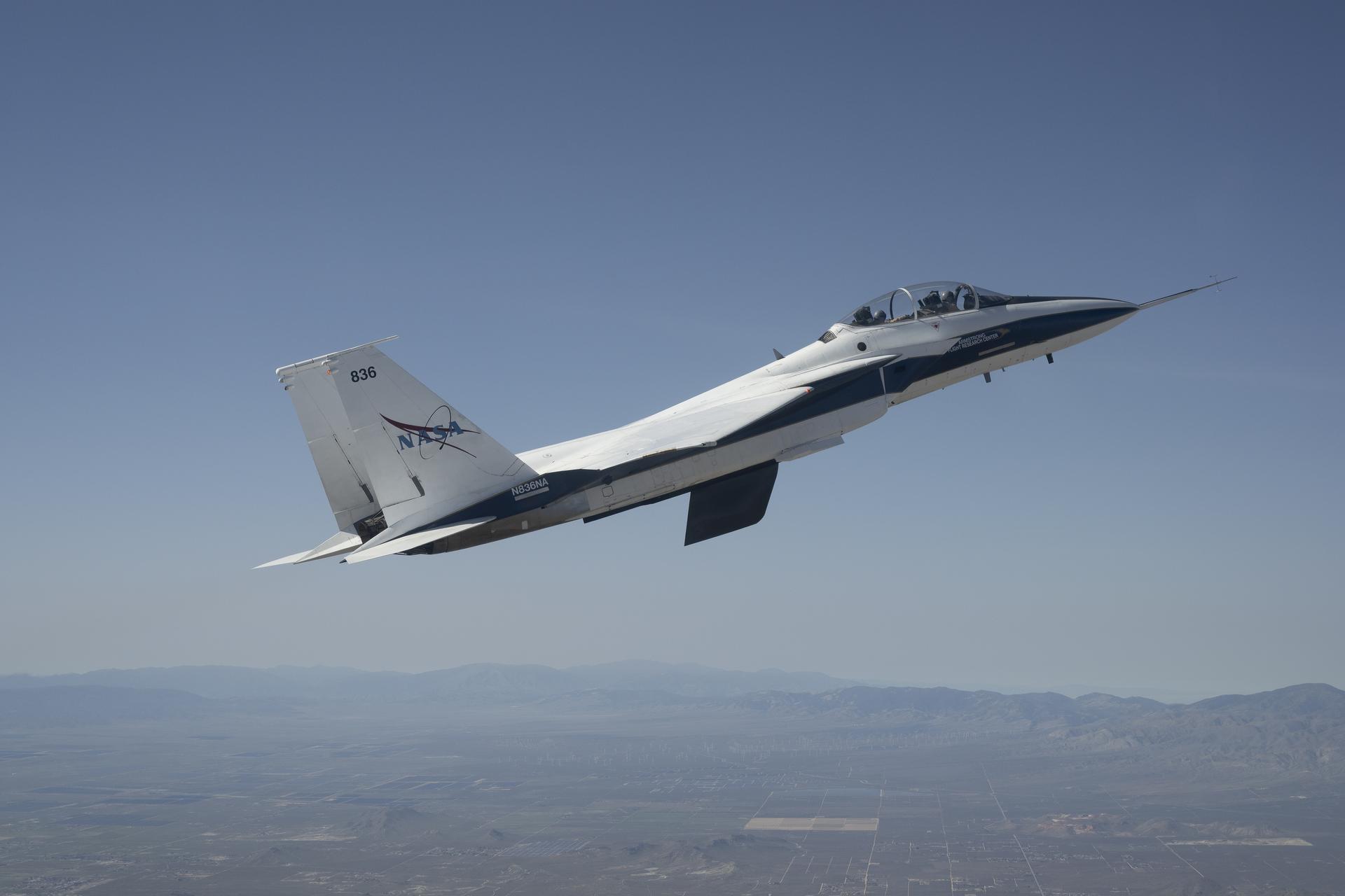
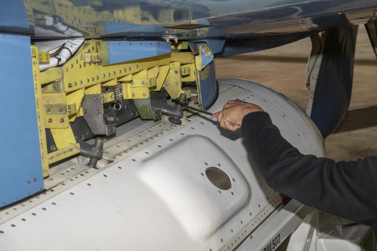
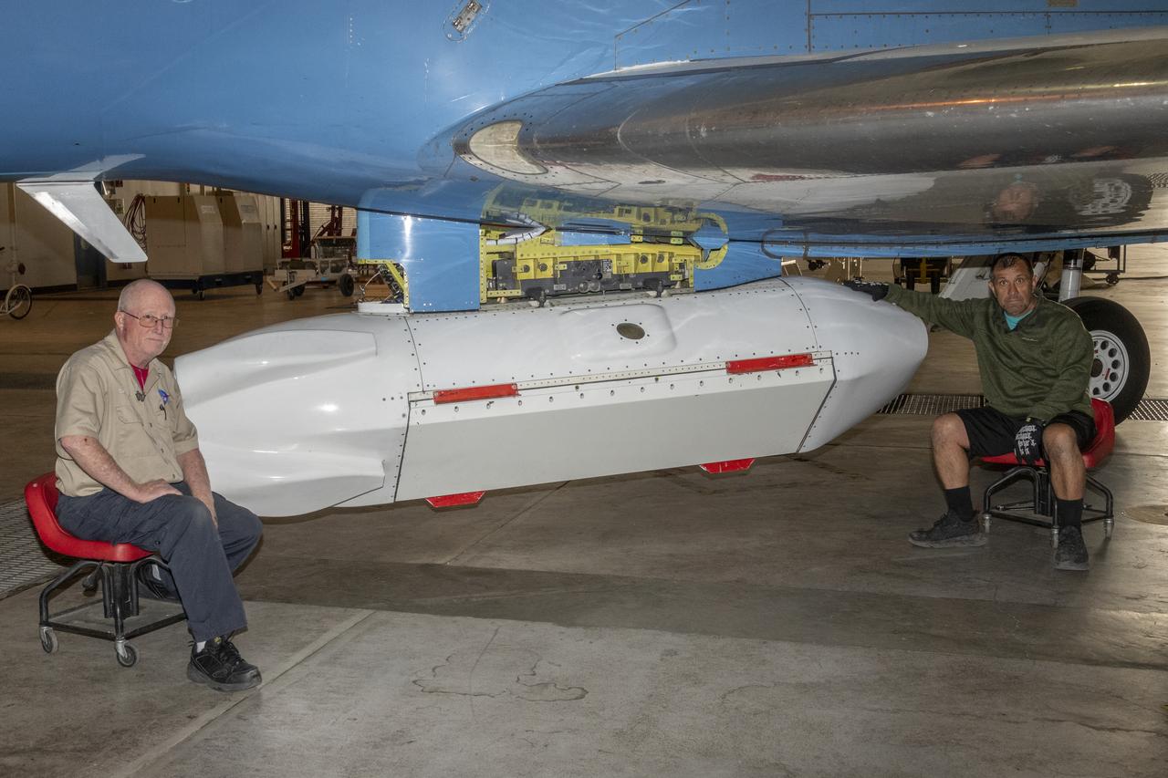
NASA’s Cross Flow Attenuated Natural Laminar Flow test article is mounted beneath the agency’s F-15 research aircraft ahead of the design’s high-speed taxi test on Tuesday, Jan. 12, 2026, at NASA’s Armstrong Flight Research Center in Edwards, California. The 3-foot-tall scale model is designed to increase a phenomenon known as laminar flow and reduce drag, improving efficiency in large, swept wings like those found on most commercial aircraft.
NASA’s Cross Flow Attenuated Natural Laminar Flow test article is mounted beneath the agency’s F-15 research aircraft ahead of the design’s high-speed taxi test on Tuesday, Jan. 12, 2026, at NASA’s Armstrong Flight Research Center in Edwards, California. The 3-foot-tall scale model is designed to increase a phenomenon known as laminar flow and reduce drag, improving efficiency in large, swept wings like those found on most commercial aircraft.
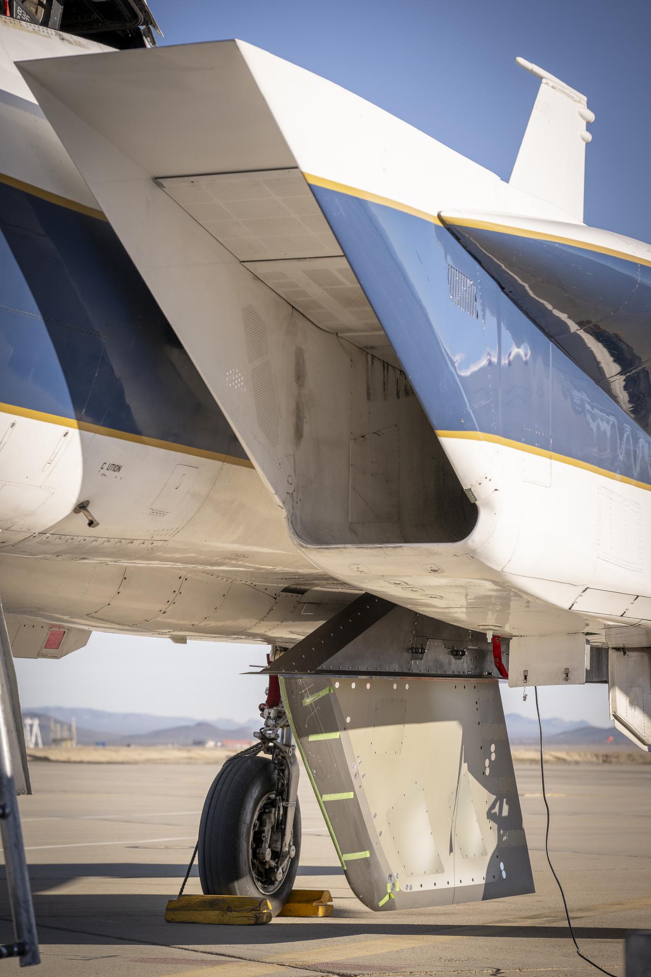
NASA’s Cross Flow Attenuated Natural Laminar Flow test article is mounted beneath the agency’s F-15 research aircraft ahead of the design’s high-speed taxi test on Tuesday, Jan. 12, 2026, at NASA’s Armstrong Flight Research Center in Edwards, California. The 3-foot-tall scale model is designed to increase a phenomenon known as laminar flow and reduce drag, improving efficiency in large, swept wings like those found on most commercial aircraft.
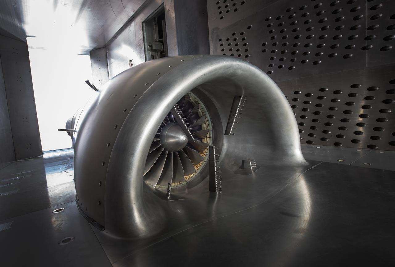
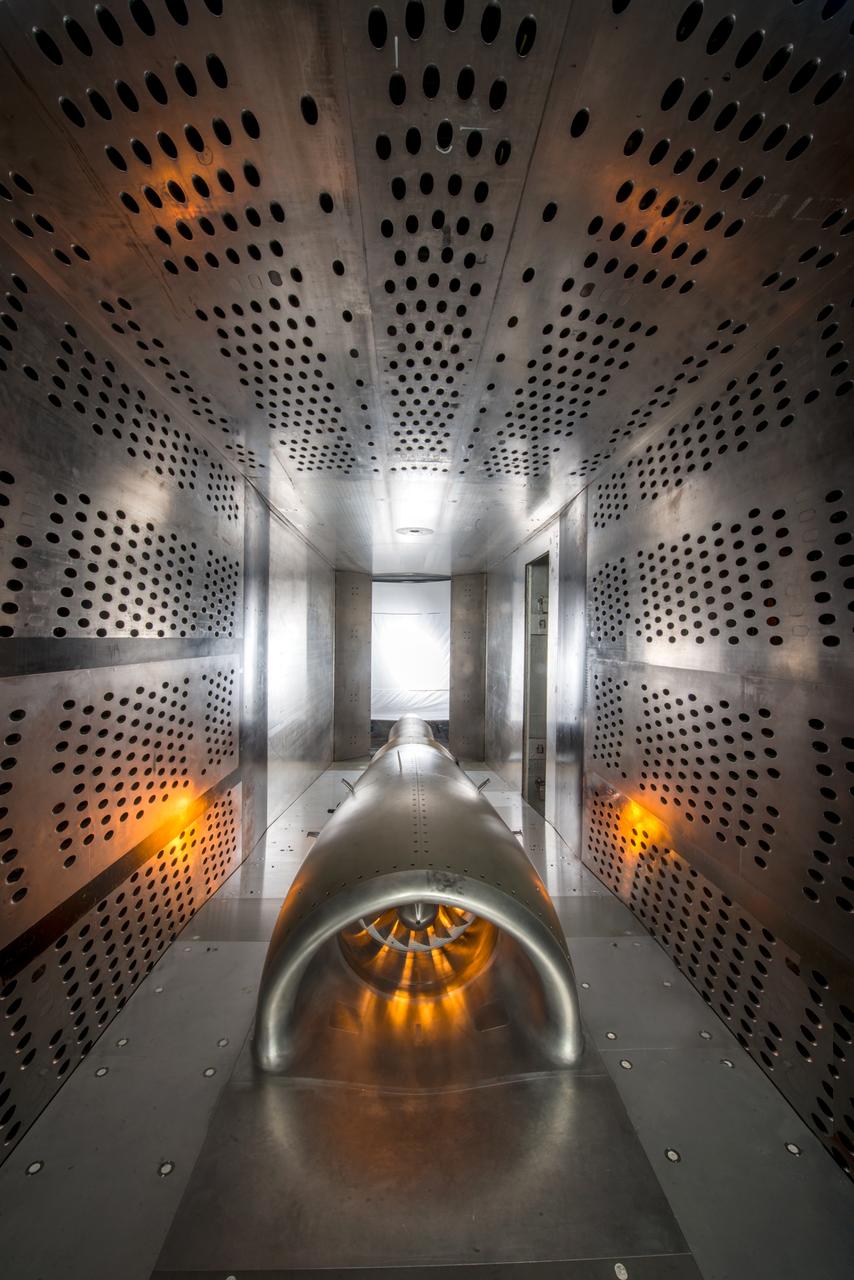
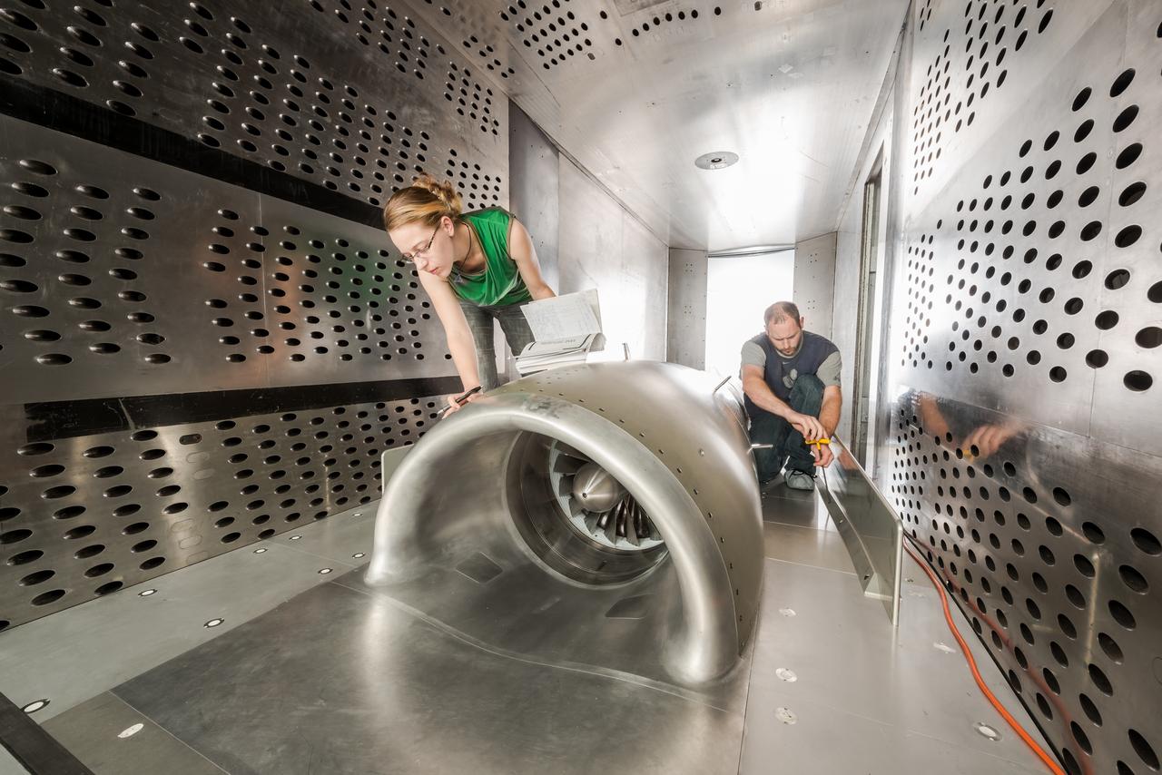
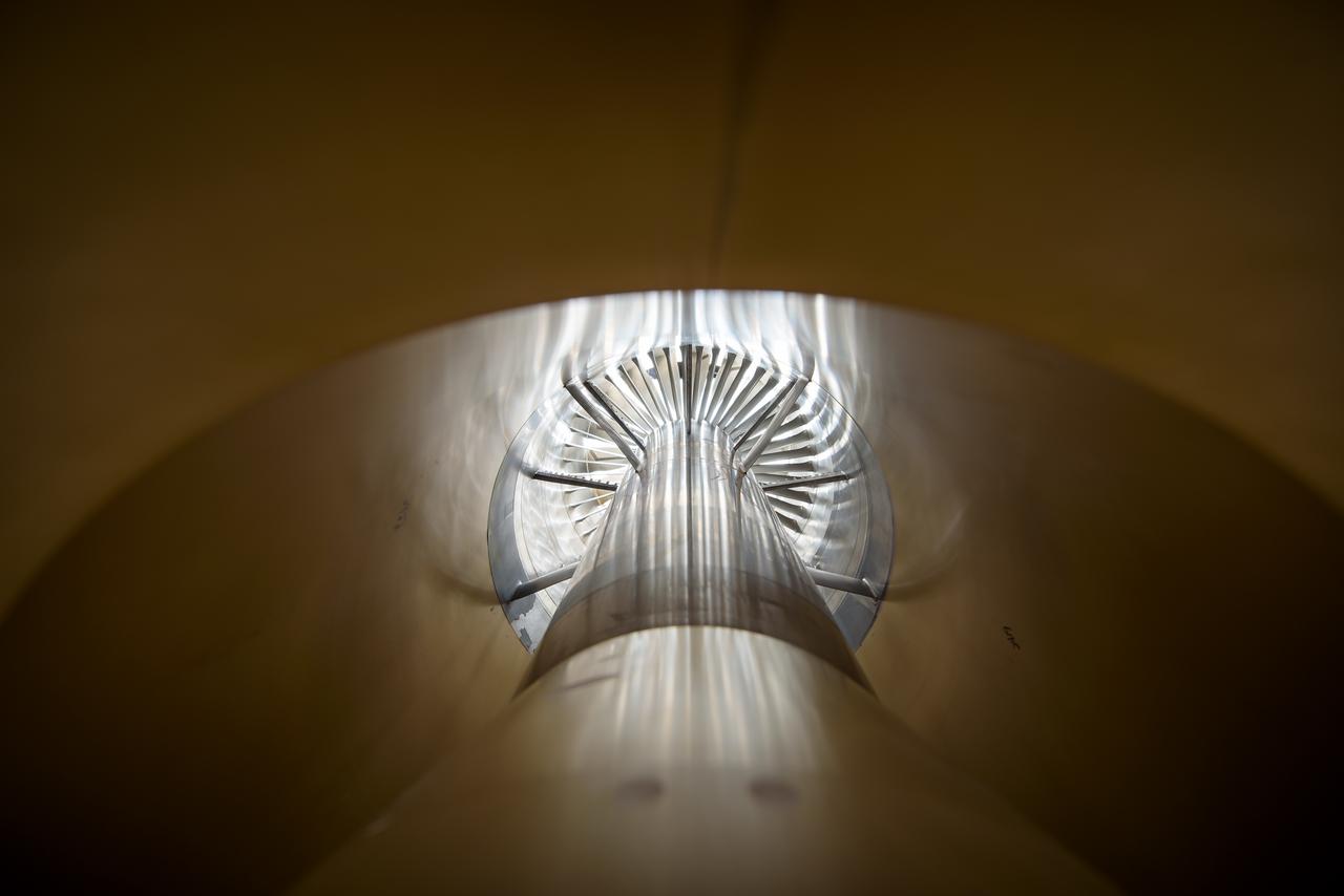
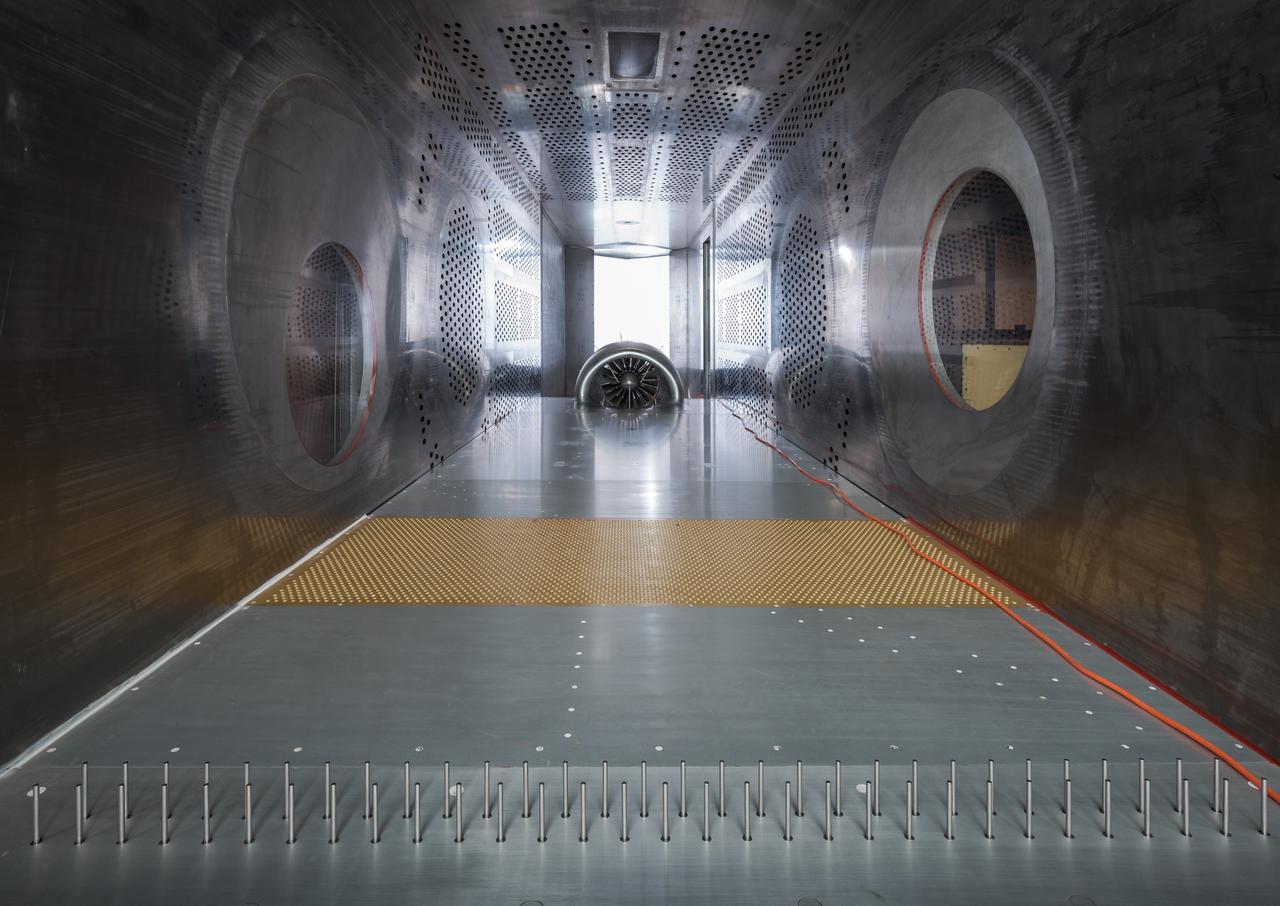
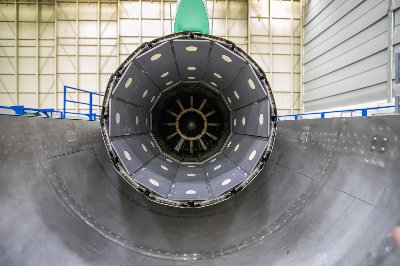
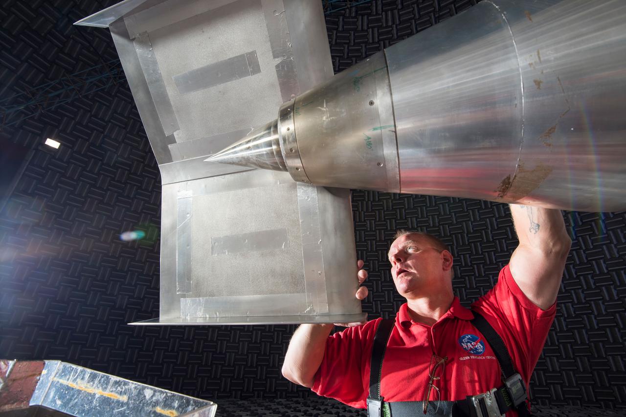
In an effort to improve fuel efficiency, NASA and the aircraft industry are rethinking aircraft design. Inside the 8' x 6' wind tunnel at NASA Glenn, engineers recently tested a fan and inlet design, commonly called a propulsor, which could use four to eight percent less fuel than today's advanced aircraft.
In an effort to improve fuel efficiency, NASA and the aircraft industry are rethinking aircraft design. Inside the 8' x 6' wind tunnel at NASA Glenn, engineers recently tested a fan and inlet design, commonly called a propulsor, which could use four to eight percent less fuel than today's advanced aircraft.
In an effort to improve fuel efficiency, NASA and the aircraft industry are rethinking aircraft design. Inside the 8' x 6' wind tunnel at NASA Glenn, engineers recently tested a fan and inlet design, commonly called a propulsor, which could use four to eight percent less fuel than today's advanced aircraft.
In an effort to improve fuel efficiency, NASA and the aircraft industry are rethinking aircraft design. Inside the 8' x 6' wind tunnel at NASA Glenn, engineers recently tested a fan and inlet design, commonly called a propulsor, which could use four to eight percent less fuel than today's advanced aircraft.
In an effort to improve fuel efficiency, NASA and the aircraft industry are rethinking aircraft design. Inside the 8' x 6' wind tunnel at NASA Glenn, engineers recently tested a fan and inlet design, commonly called a propulsor, which could use four to eight percent less fuel than today's advanced aircraft.
In an effort to improve fuel efficiency, NASA and the aircraft industry are rethinking aircraft design. Inside the 8' x 6' wind tunnel at NASA Glenn, engineers recently tested a fan and inlet design, commonly called a propulsor, which could use four to eight percent less fuel than today's advanced aircraft.
In an effort to improve fuel efficiency, NASA and the aircraft industry are rethinking aircraft design. Inside the 8' x 6' wind tunnel at NASA Glenn, engineers recently tested a fan and inlet design, commonly called a propulsor, which could use four to eight percent less fuel than today's advanced aircraft.

In an effort to improve fuel efficiency, NASA and the aircraft industry are rethinking aircraft design. Inside the 8' x 6' wind tunnel at NASA Glenn, engineers recently tested a fan and inlet design, commonly called a propulsor, which could use four to eight percent less fuel than today's advanced aircraft.

In an effort to improve fuel efficiency, NASA and the aircraft industry are rethinking aircraft design. Inside the 8' x 6' wind tunnel at NASA Glenn, engineers recently tested a fan and inlet design, commonly called a propulsor, which could use four to eight percent less fuel than today's advanced aircraft.
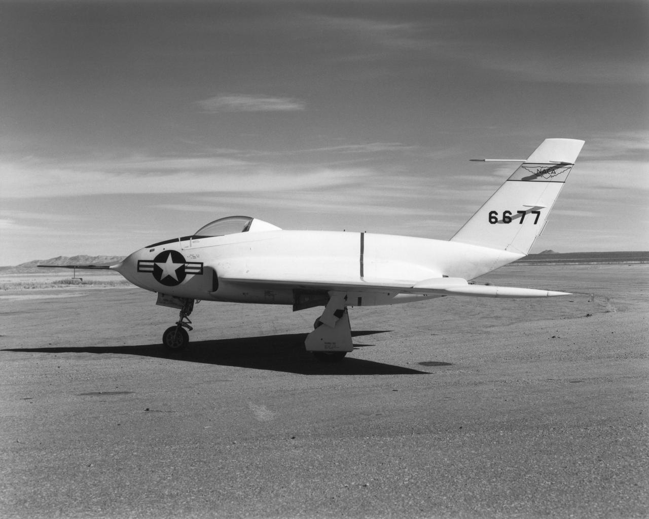
In this 1950 view of the left side of the NACA High-Speed Flight Research Station's X-4 research aircraft, the low swept wing and horizontal taillest design are seen. The X-4 Bantam, a single-place, low swept-wing, semi-tailless aircraft, was designed and built by Northrop Aircraft, Inc. It had no horizontal tail surfaces and its mission was to obtain in-flight data on the stability and control of semi-tailless aircraft at high subsonic speeds.
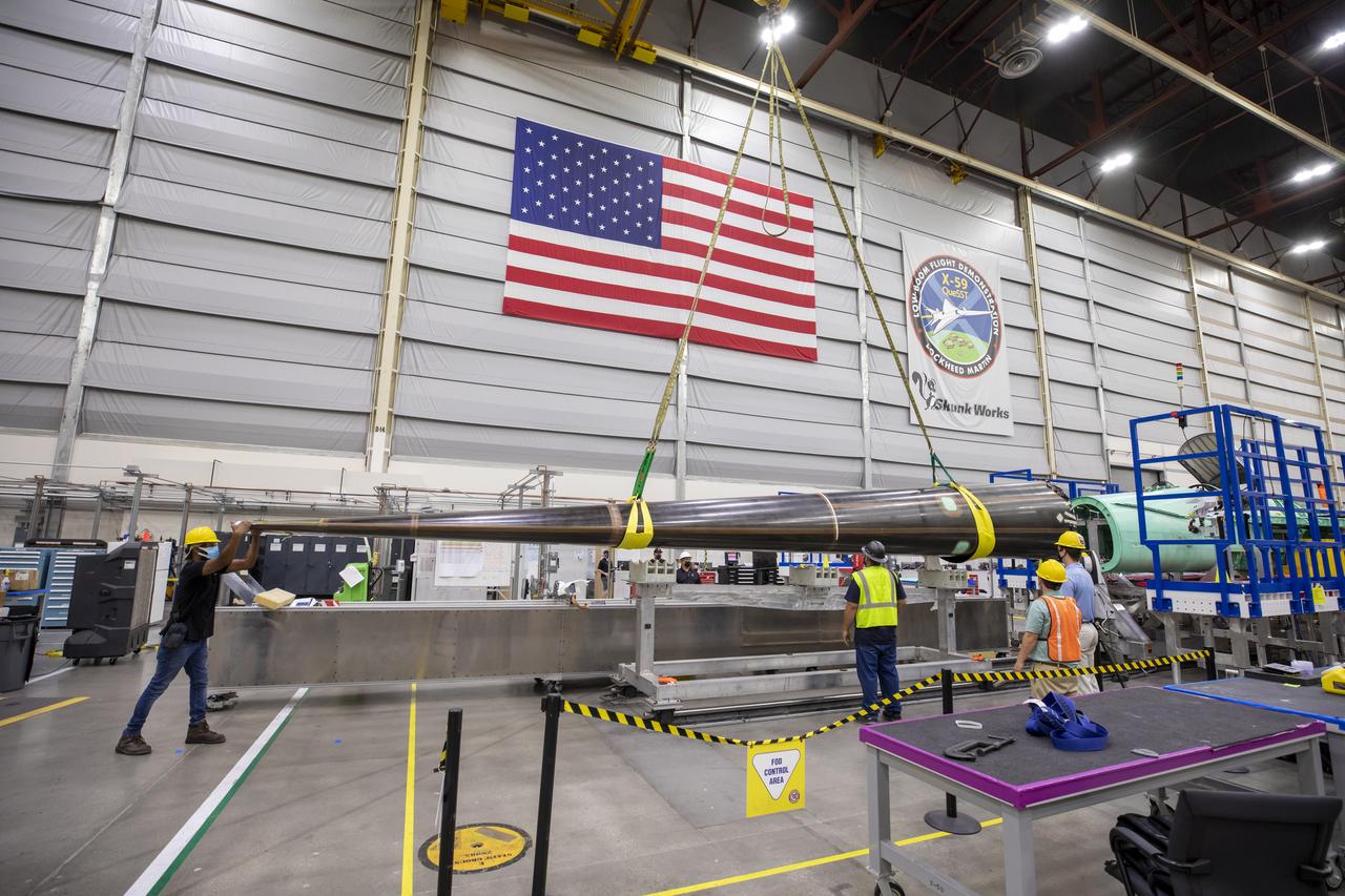
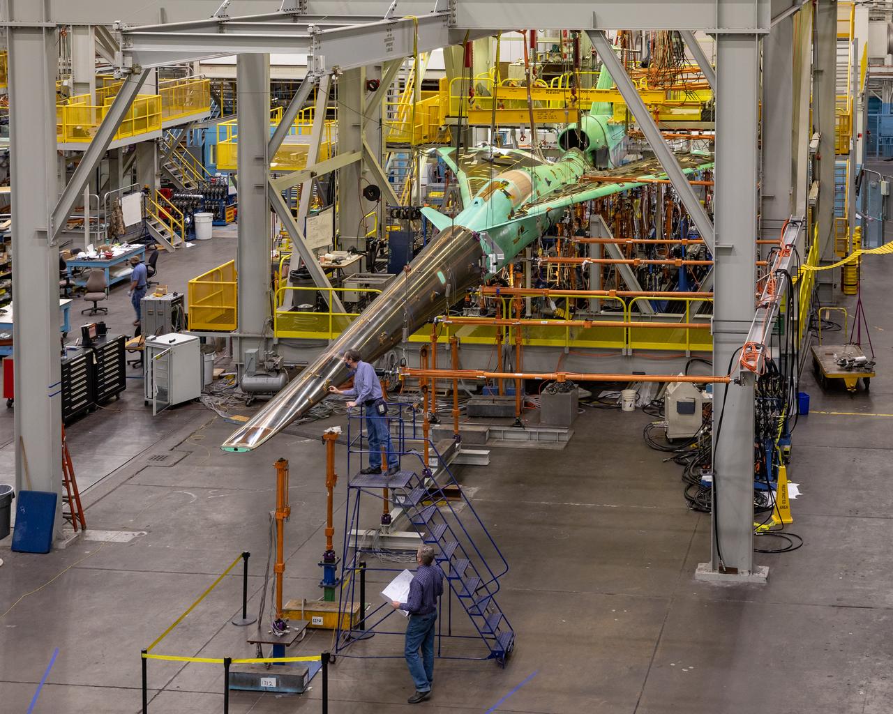
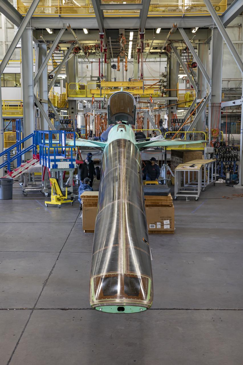
Event: SEG 230 Nose - Craned Onto Tooling A close up of the X-59’s duckbill nose, which is a crucial part of its supersonic design shaping. The team prepares the nose for a fit check. The X-59’s nose is 38-feet long – approximately one third of the length of the entire aircraft. The aircraft, under construction at Lockheed Martin Skunk Works in Palmdale, California, will demonstrate the ability to fly supersonic while reducing the loud sonic boom to a quiet sonic thump.
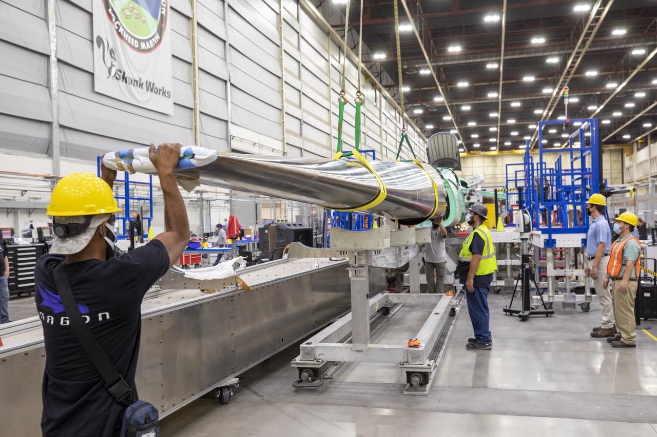
Event: SEG 230 Nose - Craned Onto Tooling A close-up of the X-59’s duckbill nose, which is a crucial part of its supersonic design shaping. The team prepares the nose for a fit check. The X-59’s nose is 38-feet long – approximately one third of the length of the entire aircraft. The aircraft, under construction at Lockheed Martin Skunk Works in Palmdale, California, will demonstrate the ability to fly supersonic while reducing the loud sonic boom to a quiet sonic thump.
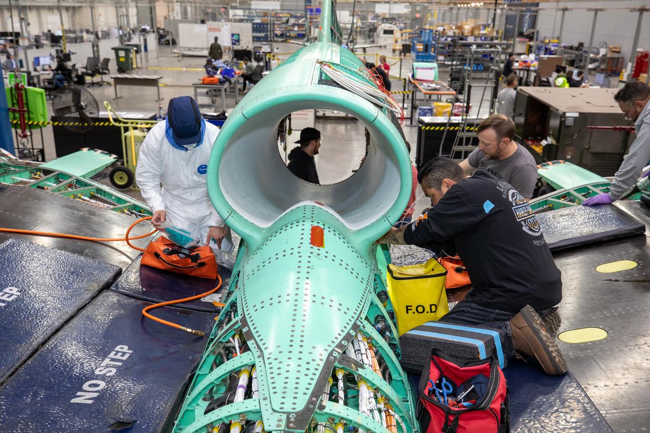
The X-59 team working on the aircraft’s wiring around the engine inlet prior to the engine being installed. Once complete, the X-59 is designed to fly supersonic while reducing the loud sonic boom. The Quesst mission could help change the rules for commercial supersonic air travel over land.
A look at the X-59’s engine nozzle, where the thrust -the force that moves the aircraft- will exit. Once complete, the X-59 is designed to fly supersonic while reducing the loud sonic boom. The Quesst mission could help change the rules for commercial supersonic air travel over land.
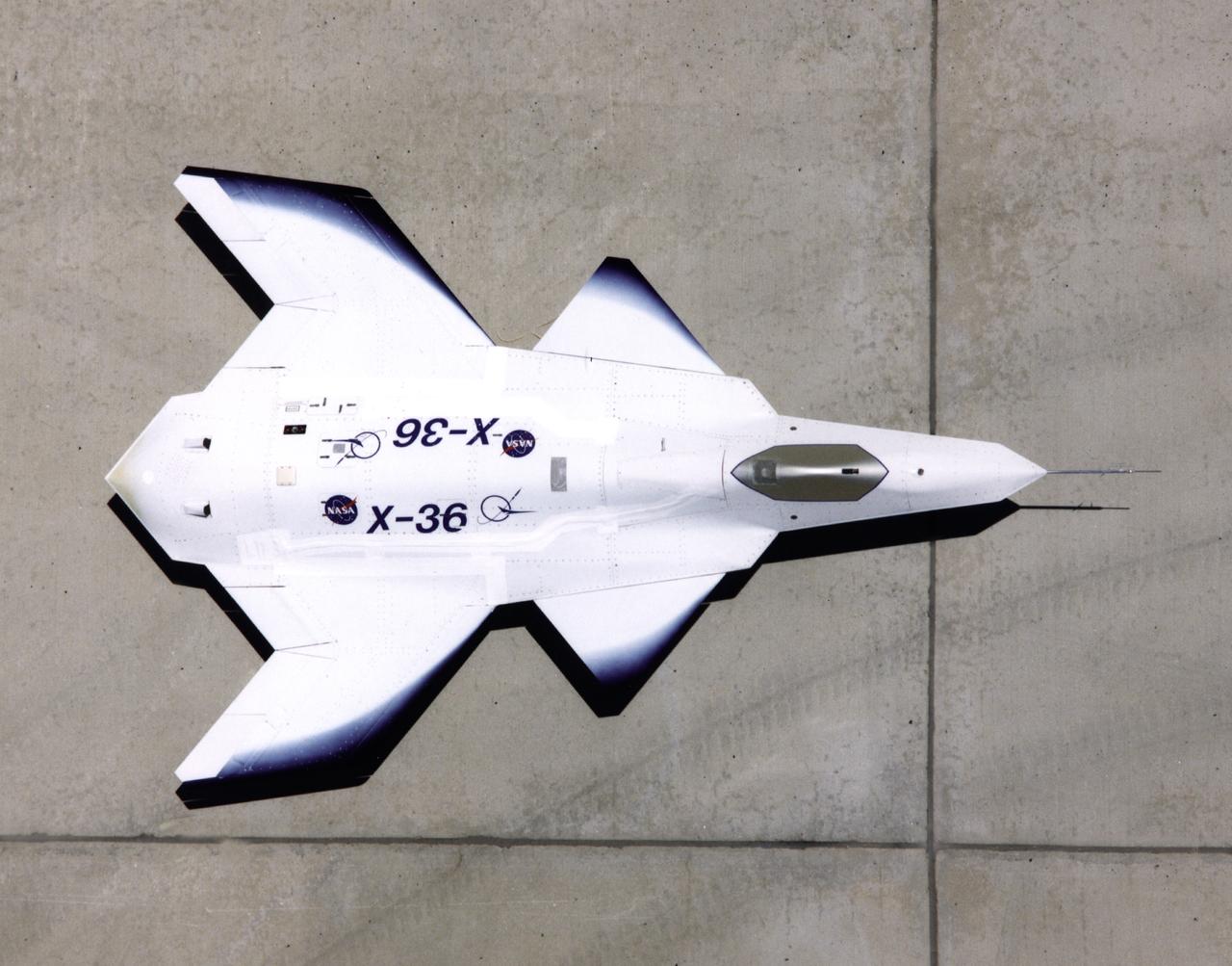
This look-down view of the X-36 Tailless Fighter Agility Research Aircraft on the ramp at NASA’s Dryden Flight Research Center, Edwards, California, clearly shows the unusual wing and canard design of the remotely-piloted aircraft.
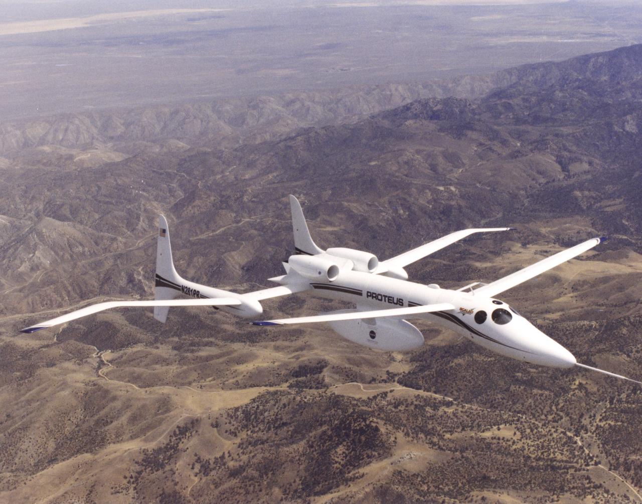
The unusual design of the Proteus high-altitude aircraft, incorporating a gull-wing shape for its main wing and a long, slender forward canard, is clearly visible in this view of the aircraft in flight over the Mojave Desert in California.
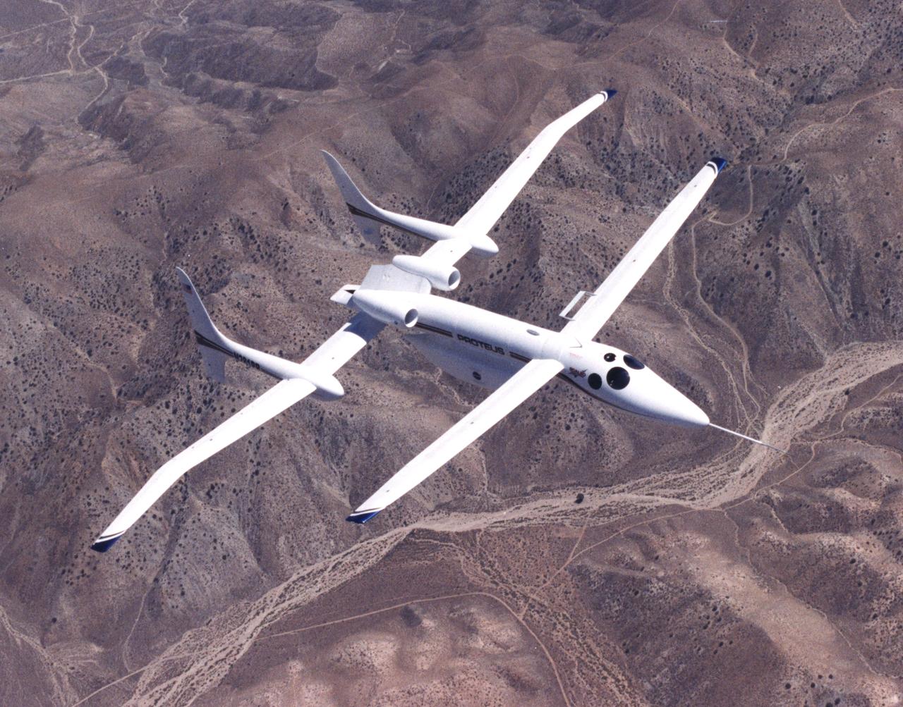
The unusual design of the Proteus high-altitude aircraft, incorporating a gull-wing shape for its main wing and a long, slender forward canard, is clearly visible in this view of the aircraft in flight over the Mojave Desert in California.
NASA’s Crossflow Attenuated Natural Laminar Flow (CATNLF) scale-model wing flies for the first time on a NASA F-15 research jet during a test flight from NASA’s Armstrong Flight Research Center in Edwards, California. The 75-minute flight confirmed the aircraft could maneuver safely with the approximately 3-foot-tall test article mounted beneath it. NASA will continue flight tests to collect data that validates the CATNLF design and its potential to improve laminar flow, reducing drag and lowering fuel costs for future commercial aircraft.
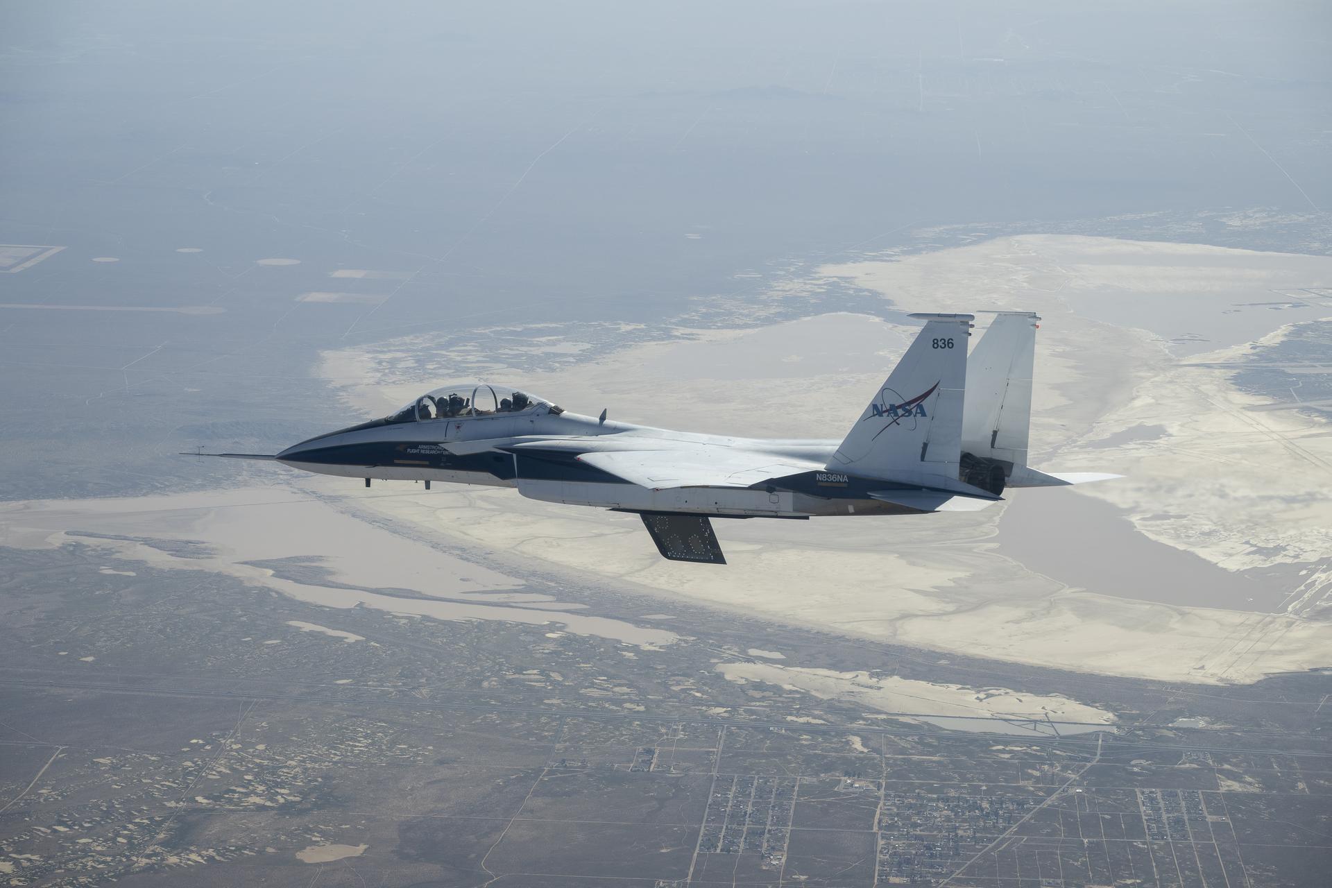
NASA’s Crossflow Attenuated Natural Laminar Flow (CATNLF) scale-model wing flies for the first time on a NASA F-15 research jet during a test flight from NASA’s Armstrong Flight Research Center in Edwards, California. The 75-minute flight confirmed the aircraft could maneuver safely with the approximately 3-foot-tall test article mounted beneath it. NASA will continue flight tests to collect data that validates the CATNLF design and its potential to improve laminar flow, reducing drag and lowering fuel costs for future commercial aircraft.

Ames engineers Allen Faye, Merrill Mead and John 'Jack' Boyd discuss aircraft design and handling
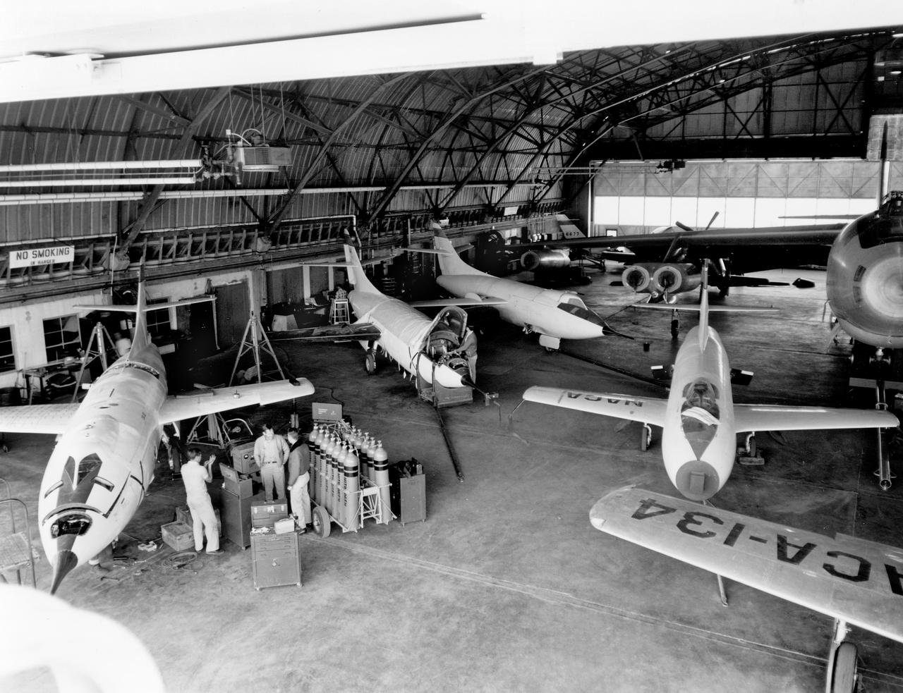
The aircraft in this 1953 photo of the National Advisory Committee for Aeronautics (NACA) hangar at South Base of Edwards Air Force Base showed the wide range of research activities being undertaken. On the left side of the hangar are the three D-558-2 research aircraft. These were designed to test swept wings at supersonic speeds approaching Mach 2. The front D-558-2 is the third built (NACA 145/Navy 37975). It has been modified with a leading-edge chord extension. This was one of a number of wing modifications, using different configurations of slats and/or wing fences, to ease the airplane's tendency to pitch-up. NACA 145 had both a jet and a rocket engine. The middle aircraft is NACA 144 (Navy 37974), the second built. It was all-rocket powered, and Scott Crossfield made the first Mach 2 flight in this aircraft on November 20, 1953. The aircraft in the back is D-558-2 number 1. NACA 143 (Navy 37973) was also carried both a jet and a rocket engine in 1953. It had been used for the Douglas contractor flights, then was turned over to the NACA. The aircraft was not converted to all-rocket power until June 1954. It made only a single NACA flight before NACA's D-558-2 program ended in 1956. Beside the three D-558-2s is the third D-558-1. Unlike the supersonic D-558-2s, it was designed for flight research at transonic speeds, up to Mach 1. The D-558-1 was jet-powered, and took off from the ground. The D-558-1's handling was poor as it approached Mach 1. Given the designation NACA 142 (Navy 37972), it made a total of 78 research flights, with the last in June 1953. In the back of the hangar is the X-4 (Air Force 46-677). This was a Northrop-built research aircraft which tested a swept wing design without horizontal stabilizers. The aircraft proved unstable in flight at speeds above Mach 0.88. The aircraft showed combined pitching, rolling, and yawing motions, and the design was considered unsuitable. The aircraft, the second X-4 built, was then used as a pilot traine
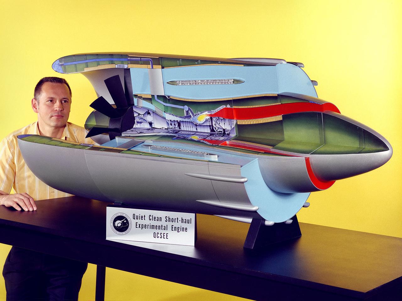
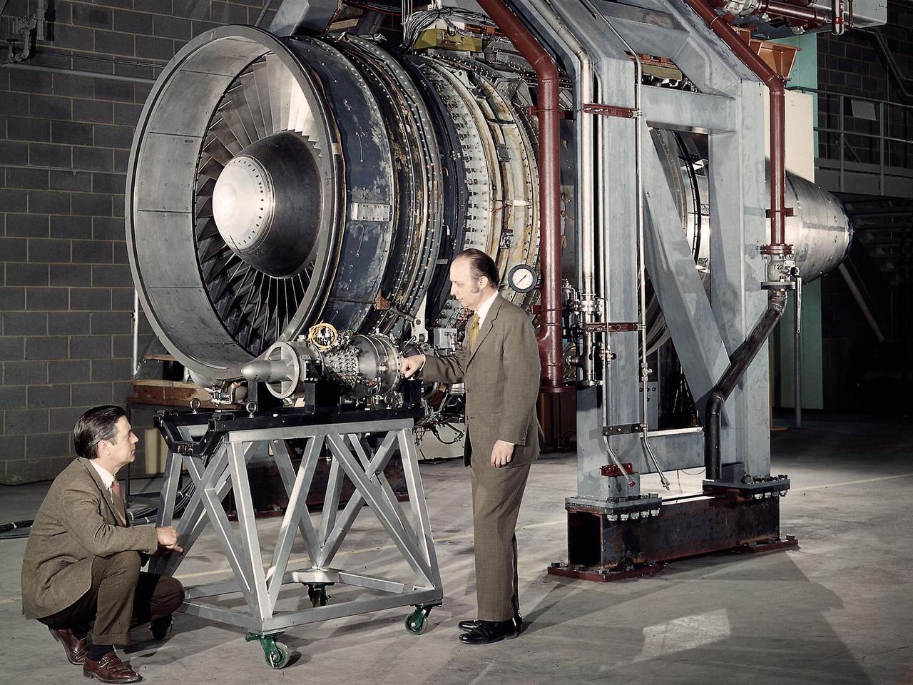
Program manager Carl Ciepluch poses with a model of the Quiet Clean Short Haul Experimental Engine (QCSEE) conceived by the National Aeronautics and Space Administration (NASA) Lewis Research Center. The QCSEE engine was designed to power future short-distance transport aircraft without generating significant levels of noise or pollution and without hindering performance. The engines were designed to be utilized on aircraft operating from small airports with short runways. Lewis researchers investigated two powered-lift designs and an array of new technologies to deal with the shorter runways. Lewis contracted General Electric to design the two QCSEE engines—one with over-the-wing power-lift and one with an under-the-wing design. A scale model of the over-the-wing engine was tested in the Full Scale Tunnel at the Langley Research Center in 1975 and 1976. Lewis researchers investigated both versions in a specially-designed test stand, the Engine Noise Test Facility, on the hangar apron. The QCSEE engines met the goals set out by the NASA researchers. The aircraft industry, however, never built the short-distance transport aircraft for which the engines were intended. Different technological elements of the engine, however, were applied to some future General Electric engines.
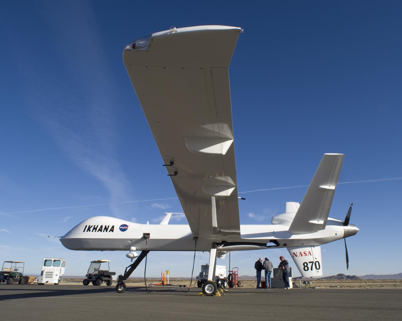
Bearing NASA tail number 870, NASA's Ikhana unmanned aircraft is a civil version of the Predator B designed for high-altitude, long-endurance science flights.
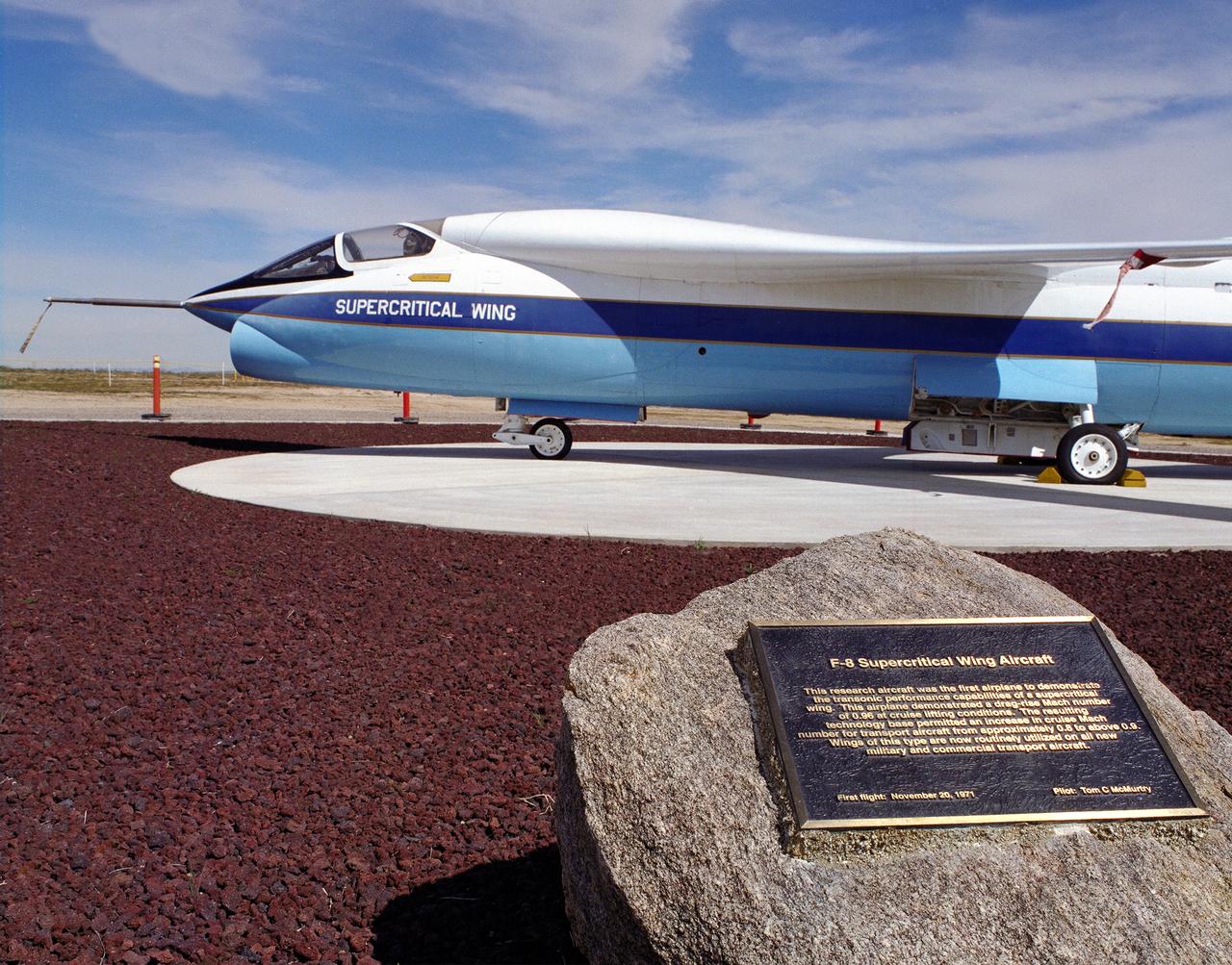
A Vought F-8A Crusader was selected by NASA as the testbed aircraft (designated TF-8A) to install an experimental Supercritical Wing (SCW) in place of the conventional wing. The unique design of the Supercritical Wing reduces the effect of shock waves on the upper surface near Mach 1, which in turn reduces drag. In the photograph the TF-8A Crusader with the Supercritical Wing is shown on static display in front of the NASA Dryden Flight Research Center, Edwards, California. The F-8 SCW aircraft, along with the F-8 Digital Fly-By-Wire aircraft were placed on display on May 27, 1992, at a conference marking the 20th anniversary of the start of the two programs.
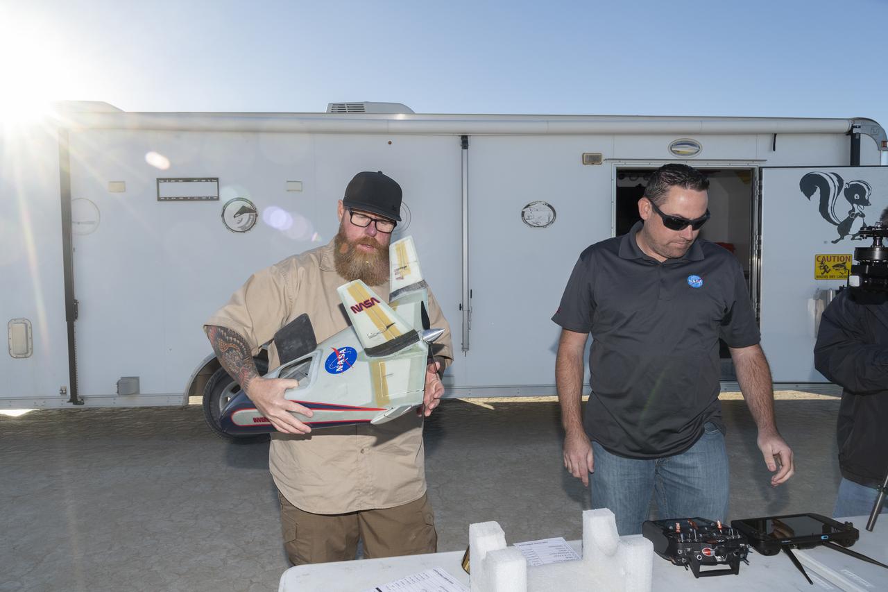
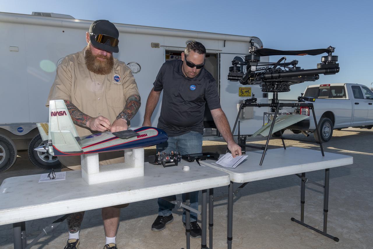
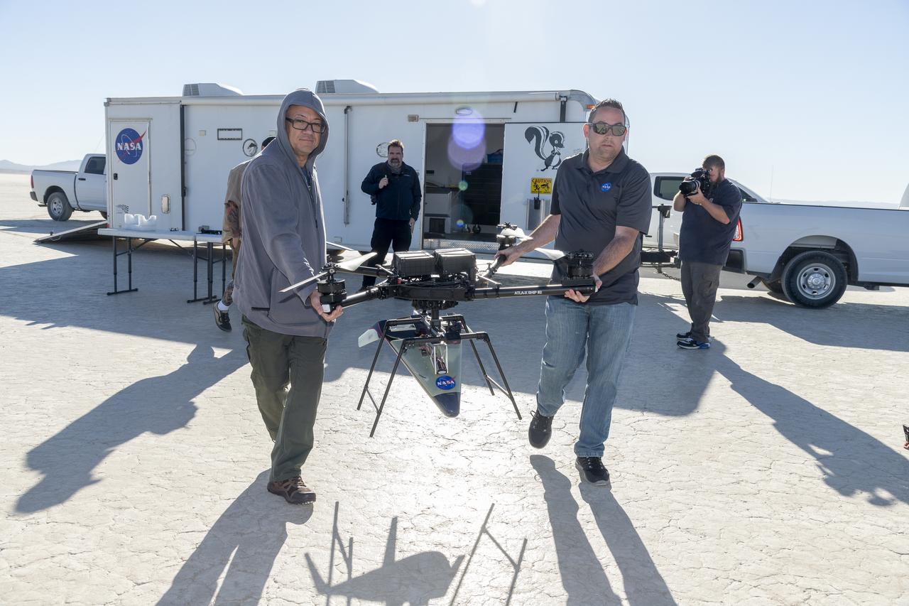
Justin Hall, left, chief pilot of small unmanned aircraft systems, carries the atmospheric probe at NASA’s Armstrong Flight Research Center in Edwards, California. The probe, which was designed and built at the center, flew after release from a quad rotor remotely piloted aircraft on Oct. 22, 2024, above Rogers Dry Lake, a flight area adjacent to the NASA center. At right, Justin Link, unmanned aircraft systems pilot, checks out the controllers for the two aircraft.
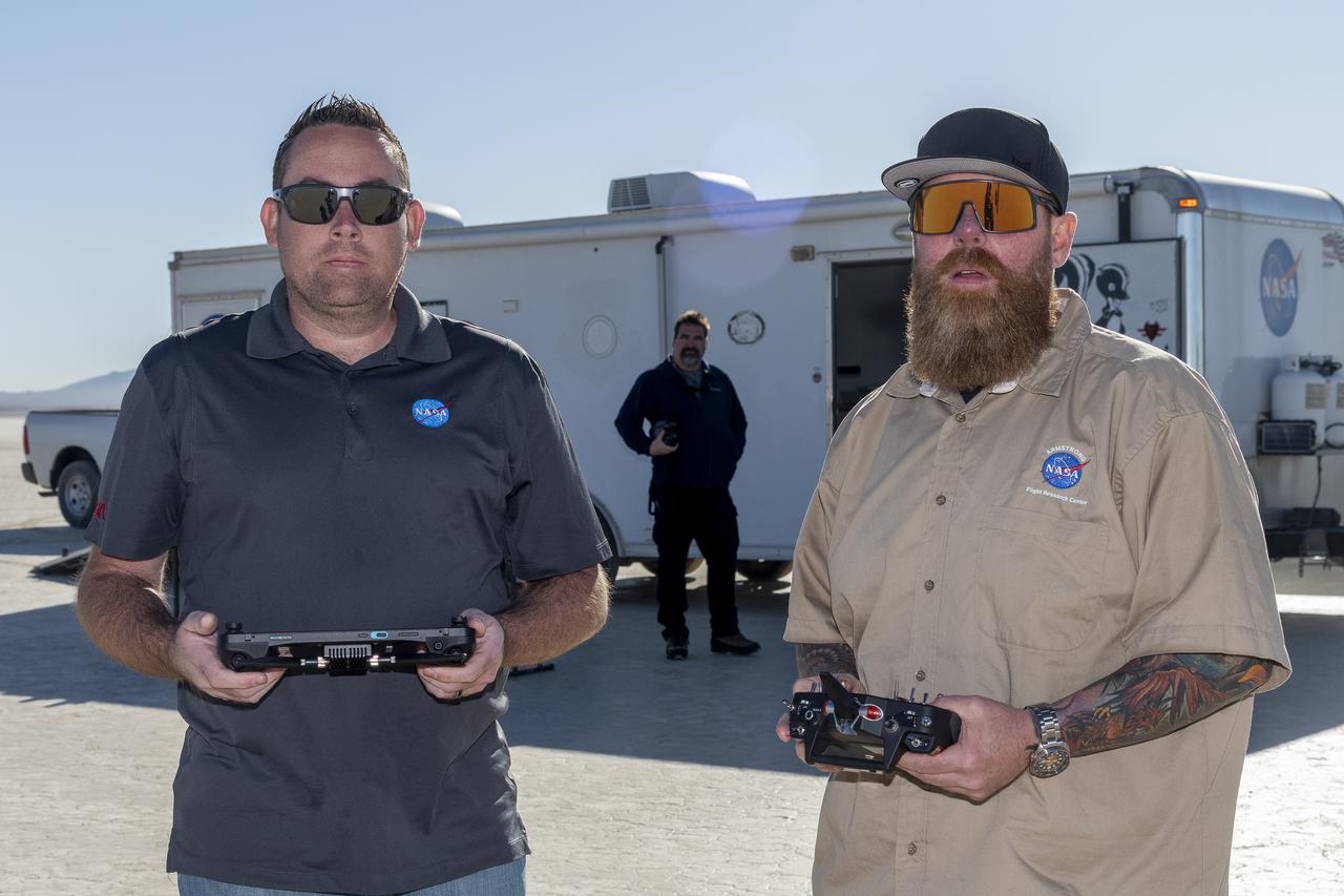
Justin Link, left, unmanned aircraft systems pilot, and Justin Hall, chief pilot for small unmanned aircraft systems, prepare to fly a quad rotor remotely piloted aircraft and an atmospheric probe model on Oct. 22, 2024. John Bodylski, probe principal investigator, watches the preparation for flight. The quad rotor aircraft released the probe above Rogers Dry Lake, a flight area adjacent NASA’s Armstrong Flight Research Center in Edwards, California. The probe was designed and built at the center.
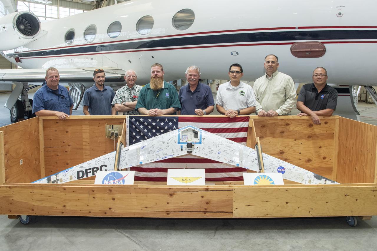
Preliminary Research Aerodynamic Design to Lower Drag, or Prandtl-D1, will be displayed in an upcoming Innovations Gallery at the National Air and Space Museum, the Smithsonian Institute. The aircraft, which flew from NASA's Armstrong Flight Research Center in California, uses a method of aircraft design that introduces a twist that results in a more efficient wing. From left are Robert "Red" Jensen, Logan Shaw, Christian Gelzer, Justin Hall, Al Bowers, Oscar Murillo, Brian Eslinger and Derek Abramson
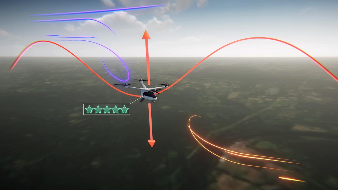
Electrical vertical takeoff and landing aircraft (eVTOLs), like the one shown in this concept art, could be a crucial part of the next generation of air transportation. In order to create a viable market, designers will have to create a comfortable passenger experience. NASA's Advanced Air Mobility mission is researching ride quality to better understand how these aircraft should be designed.
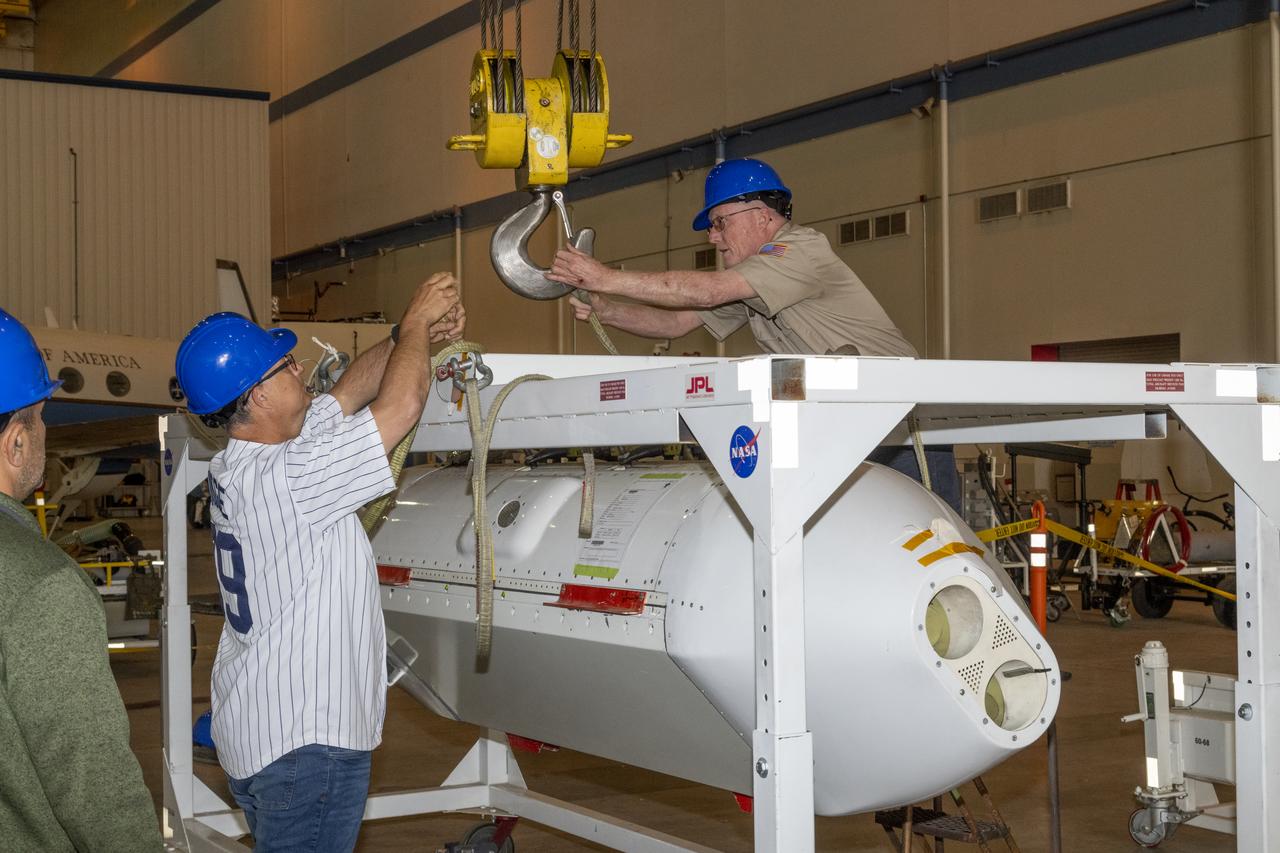
The Uninhabited Aerial Vehicle Synthetic Aperture Radar, UAVSAR, is prepared for installation onto NASA’s C-20A aircraft. THE UAVSAR uses a technique called interferometry to detect and measure very subtle deformations in the Earth’s surface, and the pod is specially designed to be interoperable with unmanned aircraft in the future. It will gather data from Gabon, Africa in September of 2023.
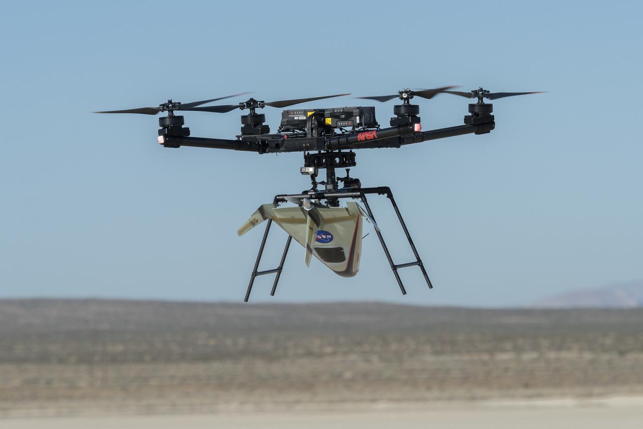
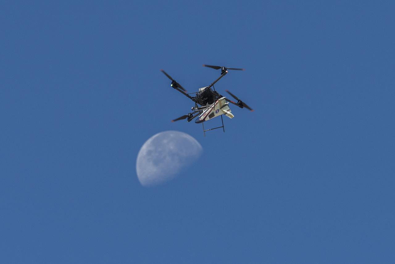
An atmospheric probe model attached upside down to a host quad rotor remotely piloted aircraft lifts off on Oct. 22, 2024. The quad rotor aircraft released the probe above Rogers Dry Lake, a flight area adjacent NASA’s Armstrong Flight Research Center in Edwards, California. The probe was designed and built at the center.
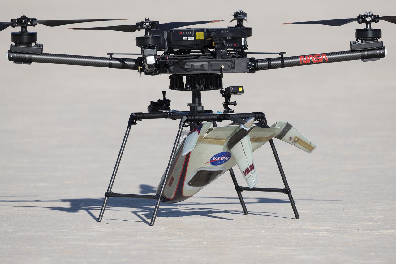
An atmospheric probe model is attached upside down to a quad rotor remotely piloted aircraft on Oct. 22, 2024. The quad rotor aircraft released the probe above Rogers Dry Lake, a flight area adjacent NASA’s Armstrong Flight Research Center in Edwards, California. The probe was designed and built at the center.
The Uninhabited Aerial Vehicle Synthetic Aperture Radar, UAVSAR, is prepared for installation onto NASA’s C-20A aircraft. THE UAVSAR uses a technique called interferometry to detect and measure very subtle deformations in the Earth’s surface, and the pod is specially designed to be interoperable with unmanned aircraft in the future. It will gather data from Gabon, Africa in September of 2023.
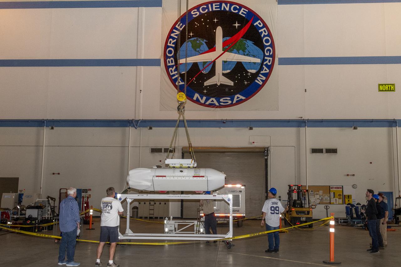
The Uninhabited Aerial Vehicle Synthetic Aperture Radar, UAVSAR, is prepared for installation onto NASA’s C-20A aircraft. THE UAVSAR uses a technique called interferometry to detect and measure very subtle deformations in the Earth’s surface, and the pod is specially designed to be interoperable with unmanned aircraft in the future. It will gather data from Gabon, Africa in September of 2023.
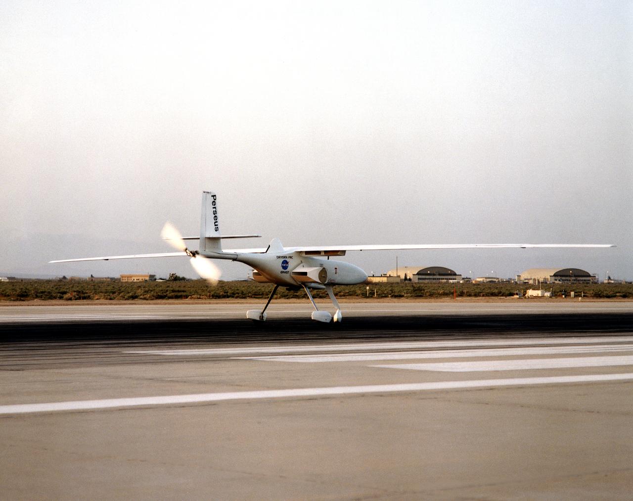
The Perseus B remotely piloted aircraft on the runway at Edwards Air Force Base, California at the conclusion of a development flight at NASA's Dryden flight Research Center. The Perseus B is the latest of three versions of the Perseus design developed by Aurora Flight Sciences under NASA's Environmental Research Aircraft and Sensor Technology (ERAST) program.
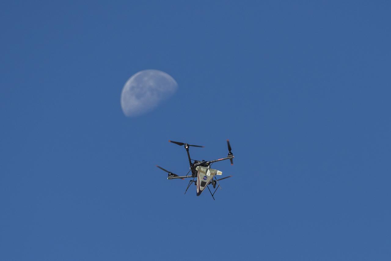
An atmospheric probe model attached upside down to a quad rotor remotely piloted aircraft ascends with the Moon visible on Oct. 22, 2024. The quad rotor aircraft released the probe above Rogers Dry Lake, a flight area adjacent NASA’s Armstrong Flight Research Center in Edwards, California. The probe was designed and built at the center.
An atmospheric probe model attached upside down to a quad rotor remotely piloted aircraft ascends with the Moon visible on Oct. 22, 2024. The quad rotor aircraft released the probe above Rogers Dry Lake, a flight area adjacent NASA’s Armstrong Flight Research Center in Edwards, California. The probe was designed and built at the center.
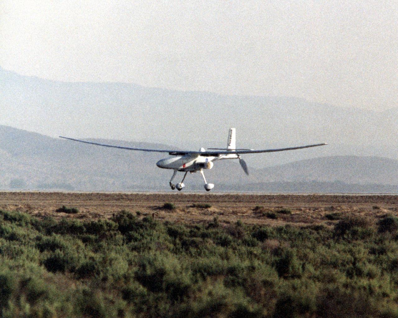
The Perseus B remotely piloted aircraft nears touchdown at Edwards Air Force Base, Calif. at the conclusion of a development flight at NASA's Dryden Flight Research Center. The Perseus B is the latest of three versions of the Perseus design developed by Aurora Flight Sciences under NASA's Environmental Research Aircraft and Sensor Technology (ERAST) program.

The MicroCub is the newest addition to NASA Armstrong's fleet of subscale research aircraft. The aircraft is a modified a Bill Hempel 60-percent-scale super cub, designed with a 21-foot wingspan, a Piccolo Autopilot guidance system and a JetCat SPT-15 Turboprop.
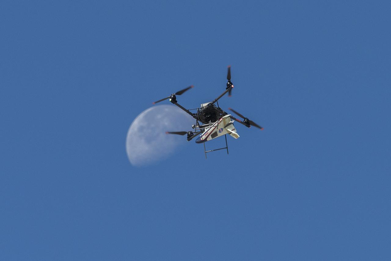
An atmospheric probe model attached upside down to a quad rotor remotely piloted aircraft ascends with the Moon visible on Oct. 22, 2024. The quad rotor aircraft released the probe above Rogers Dry Lake, a flight area adjacent NASA’s Armstrong Flight Research Center in Edwards, California. The probe was designed and built at the center.

The Uninhabited Aerial Vehicle Synthetic Aperture Radar, UAVSAR, is prepared for installation onto NASA’s C-20A aircraft. THE UAVSAR uses a technique called interferometry to detect and measure very subtle deformations in the Earth’s surface, and the pod is specially designed to be interoperable with unmanned aircraft in the future. It will gather data from Gabon, Africa in September of 2023.
The Uninhabited Aerial Vehicle Synthetic Aperture Radar, UAVSAR, is prepared for installation onto NASA’s C-20A aircraft. THE UAVSAR uses a technique called interferometry to detect and measure very subtle deformations in the Earth’s surface, and the pod is specially designed to be interoperable with unmanned aircraft in the future. It will gather data from Gabon, Africa in September of 2023.

An atmospheric probe model attached upside down to a quad rotor remotely piloted aircraft ascends with the Moon visible on Oct. 22, 2024. The quad rotor aircraft released the probe above Rogers Dry Lake, a flight area adjacent NASA’s Armstrong Flight Research Center in Edwards, California. The probe was designed and built at the center.
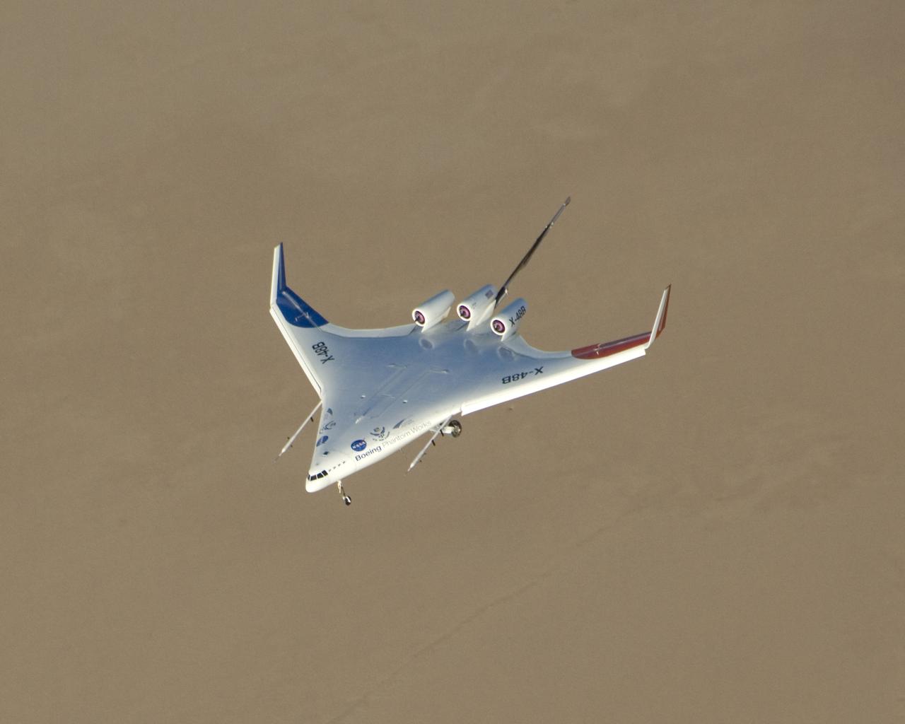
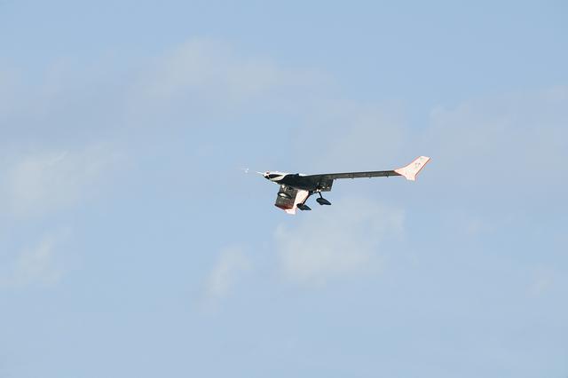
Boeing Phantom Works' subscale Blended Wing Body technology demonstration aircraft began its initial flight tests from NASA's Dryden Flight Research Center at Edwards Air Force Base, Calif. in the summer of 2007. The 8.5 percent dynamically scaled unmanned aircraft, designated the X-48B by the Air Force, is designed to mimic the aerodynamic characteristics of a full-scale large cargo transport aircraft with the same blended wing body shape. The initial flight tests focused on evaluation of the X-48B's low-speed flight characteristics and handling qualities. About 25 flights were planned to gather data in these low-speed flight regimes. Based on the results of the initial flight test series, a second set of flight tests was planned to test the aircraft's low-noise and handling characteristics at transonic speeds.
Justin Hall, chief pilot of small unmanned aircraft systems, prepares the atmospheric probe for flight above Rogers Dry Lake, a flight area adjacent NASA’s Armstrong Flight Research Center in Edwards, California. At right, Justin Link, small unmanned aircraft systems pilot, assists. The probe, designed and built at the center, flew after release from a quad rotor remotely piloted aircraft on Oct. 22, 2024.
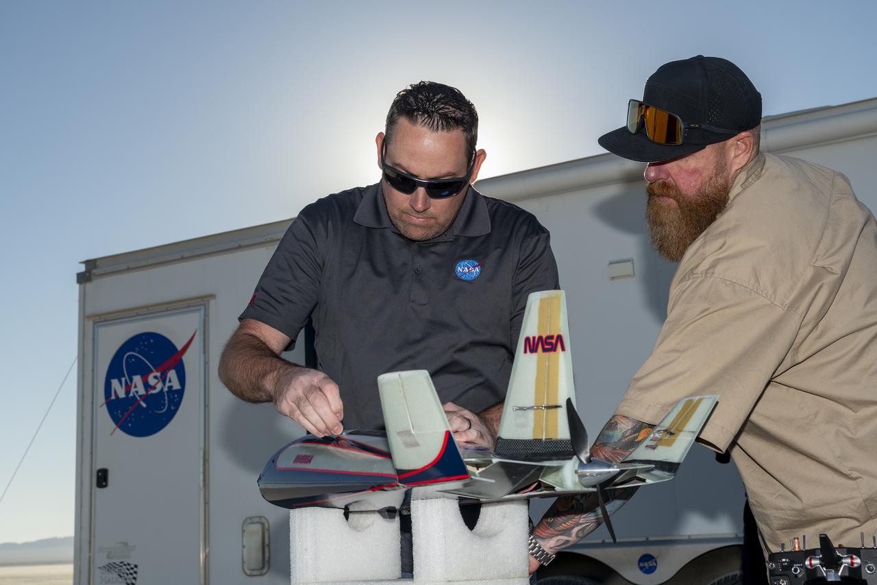
Justin Link, left, small unmanned aircraft systems pilot, and Justin Hall, chief pilot of small unmanned aircraft systems, prepare an atmospheric probe model for flight on Oct. 22, 2024. A quad rotor remotely piloted aircraft released the probe above Rogers Dry Lake, a flight area adjacent NASA’s Armstrong Flight Research Center in Edwards, California. The probe was designed and built at the center.
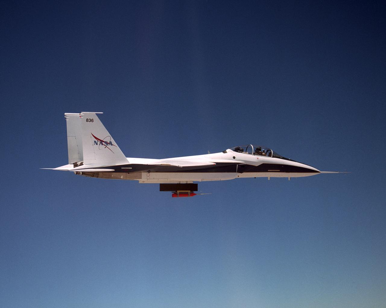
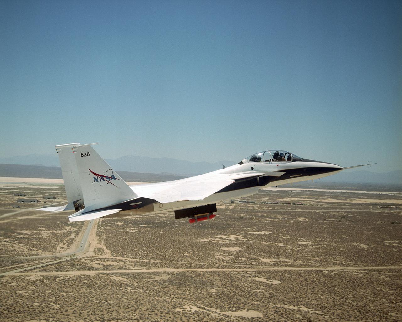
NASA's F-15B Research Testbed aircraft flew instrumentation in June 2004 called the Local Mach Investigation (LMI), designed to gather local airflow data for future research projects using the aircraft's Propulsion Flight Test Fixture (PFTF). The PFTF is the black rectangular fixture attached to the aircraft's belly. The LMI package was located in the orange device attached to the PFTF.
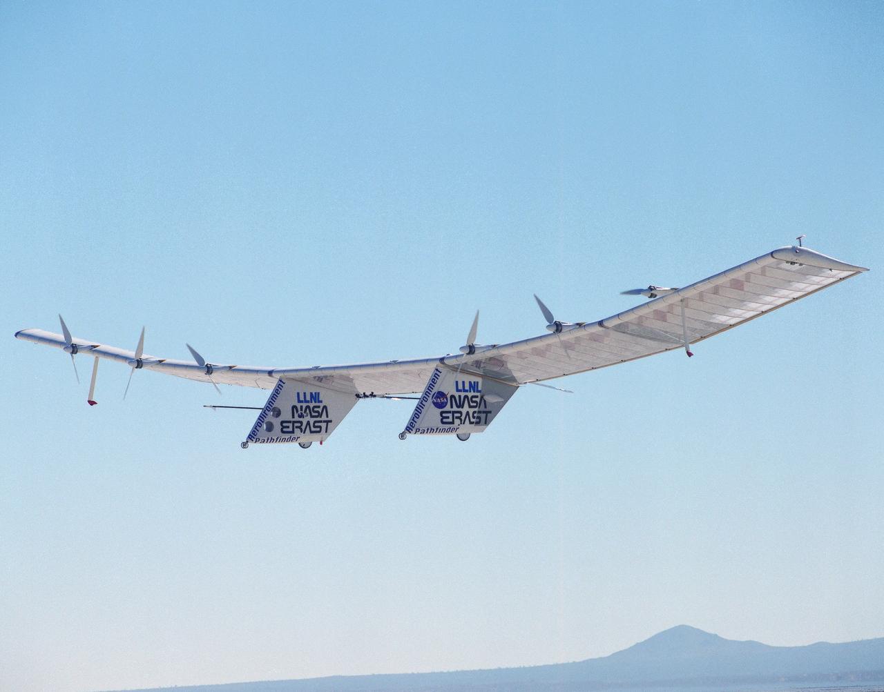
The Pathfinder solar-powered remotely piloted aircraft climbs to a record-setting altitude of 50,567 feet during a flight Sept. 11, 1995, at NASA's Dryden Flight Research Center, Edwards, California. The flight was part of the NASA ERAST (Environmental Research Aircraft and Sensor Technology) program. The Pathfinder was designed and built by AeroVironment Inc., Monrovia, California. Solar arrays cover nearly all of the upper wing surface and produce electricity to power the aircraft's six motors.
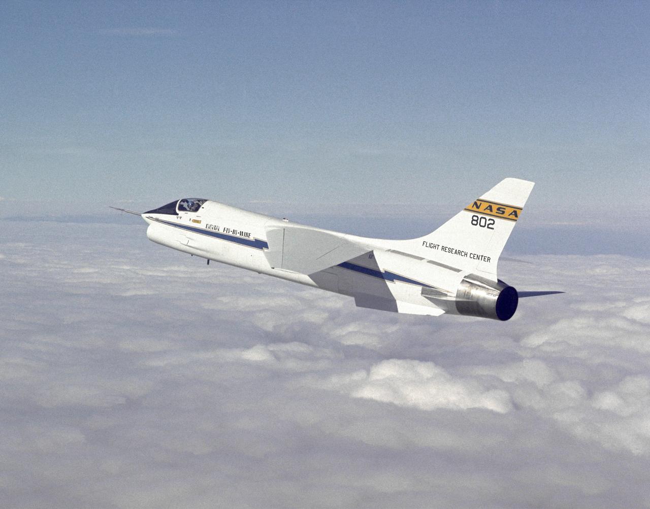
F-8 Digital Fly-By-Wire aircraft in flight. The computer-controlled flight systems pioneered by the F-8 DFBW created a revolution in aircraft design. The F-117A, X-29, X-31, and many other aircraft have relied on computers to make them flyable. Built with inherent instabilities to make them more maneuverable, they would be impossible for human pilots to fly if the computers failed or received incorrect data.

NASA's F-15B Research Testbed aircraft flew instrumentation in June 2004 called the Local Mach Investigation (LMI), designed to gather local airflow data for future research projects using the aircraft's Propulsion Flight Test Fixture (PFTF). The PFTF is the black rectangular fixture attached to the aircraft's belly. The LMI package was located in the orange device attached to the PFTF.
NASA's F-15B Research Testbed aircraft flew instrumentation in June 2004 called the Local Mach Investigation (LMI), designed to gather local airflow data for future research projects using the aircraft's Propulsion Flight Test Fixture (PFTF). The PFTF is the black rectangular fixture attached to the aircraft's belly. The LMI package was located in the orange device attached to the PFTF.
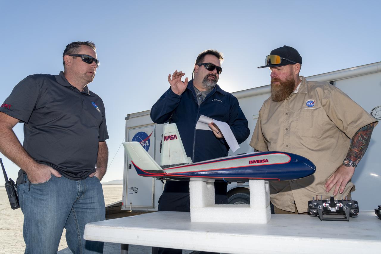
Justin Link, left, small unmanned aircraft systems pilot; John Bodylski, atmospheric probe principal investigator; and Justin Hall, chief pilot of small unmanned aircraft systems, discuss details of the atmospheric probe flight plan on Oct. 22, 2024. A quad rotor remotely piloted aircraft released the probe above Rogers Dry Lake, a flight area adjacent NASA’s Armstrong Flight Research Center in Edwards, California. The probe was designed and built at the center.
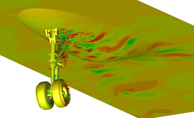
Snapshot from a simulation run on the Pleiades supercomputer. It depicts a fluctuating pressure field on aircraft nose landing gear and fuselage surfaces. The simulation helped scientists better understand the effects of landing gear and acoustic noise. The goal of the study was to improve the current understanding of aircraft nose landing gear noise, which will lead to quieter, more efficient airframe components for future aircraft designs. The visualization was produced with help from the NAS Data Analysis & Visualization group. Investigator: Mehdi Khorrami, NASA Langley Research Center.
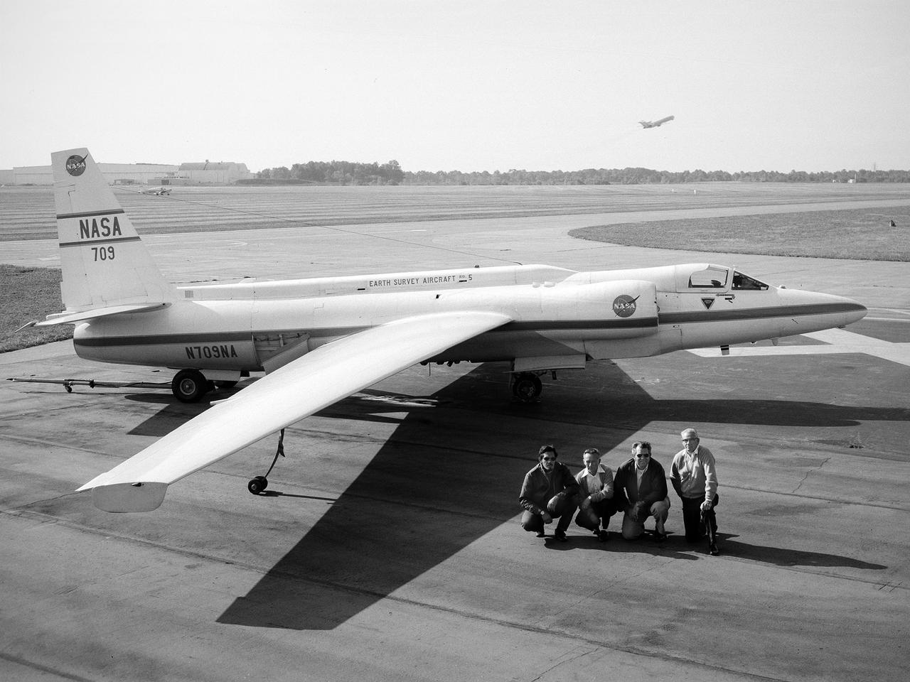
A National Aeronautics and Space Administration (NASA) Lockheed U-2 aircraft on display at the 1973 Inspection of the Lewis Research Center in Cleveland, Ohio. Lockheed developed the U-2 as a high-altitude reconnaissance aircraft in the early 1950s before satellites were available. The U-2 could cruise over enemy territory at 70,000 feet and remain impervious to ground fire, interceptor aircraft, and even radar. An advanced camera system was designed specifically for the aircraft. The pilot is required to use a pressure suit similar to those worn by astronauts. NASA’s Ames Research Center received two U-2 aircraft in April 1971 to conduct high-altitude research. They were used to study and monitor various Earth resources, celestial bodies, atmospheric chemistry, and oceanic processes. NASA replaced its U-2s with ER-2 aircraft in 1981 and 1989. The ER-2s were designed to carry up to 2600 pounds of scientific equipment. The ER-2 program was transferred to Dryden Flight Research Center in 1997. Since the inaugural flight for this program on August 31, 1971, NASA’s U-2 and ER-2 aircraft have flown more than 4500 data missions and test flights for NASA, other federal agencies, states, universities, and the private sector.

A wood router cuts precise holes in plywood for temporary floorboards on Aug. 26, 2024, in the Experimental Fabrication Shop at NASA’s Armstrong Flight Research Center in Edwards, California. The flooring was designed for the X-66 experimental demonstrator aircraft.
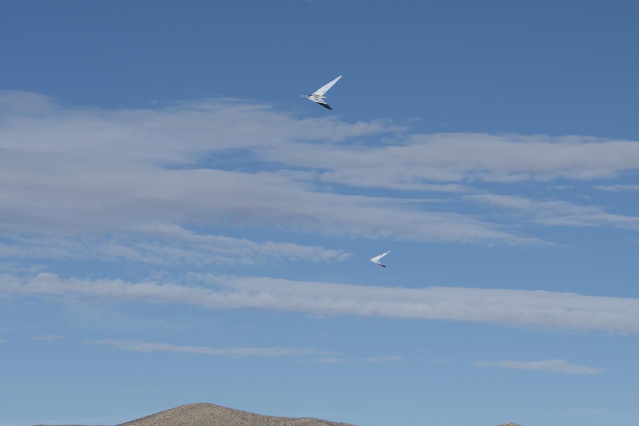
NASA Armstrong Flight Research Center conducted its first formation flight with the Preliminary Research Aerodynamic Design to Lower Drag (Prandtl) aircrafts Prandtl-D2 and Prandtl-3C.
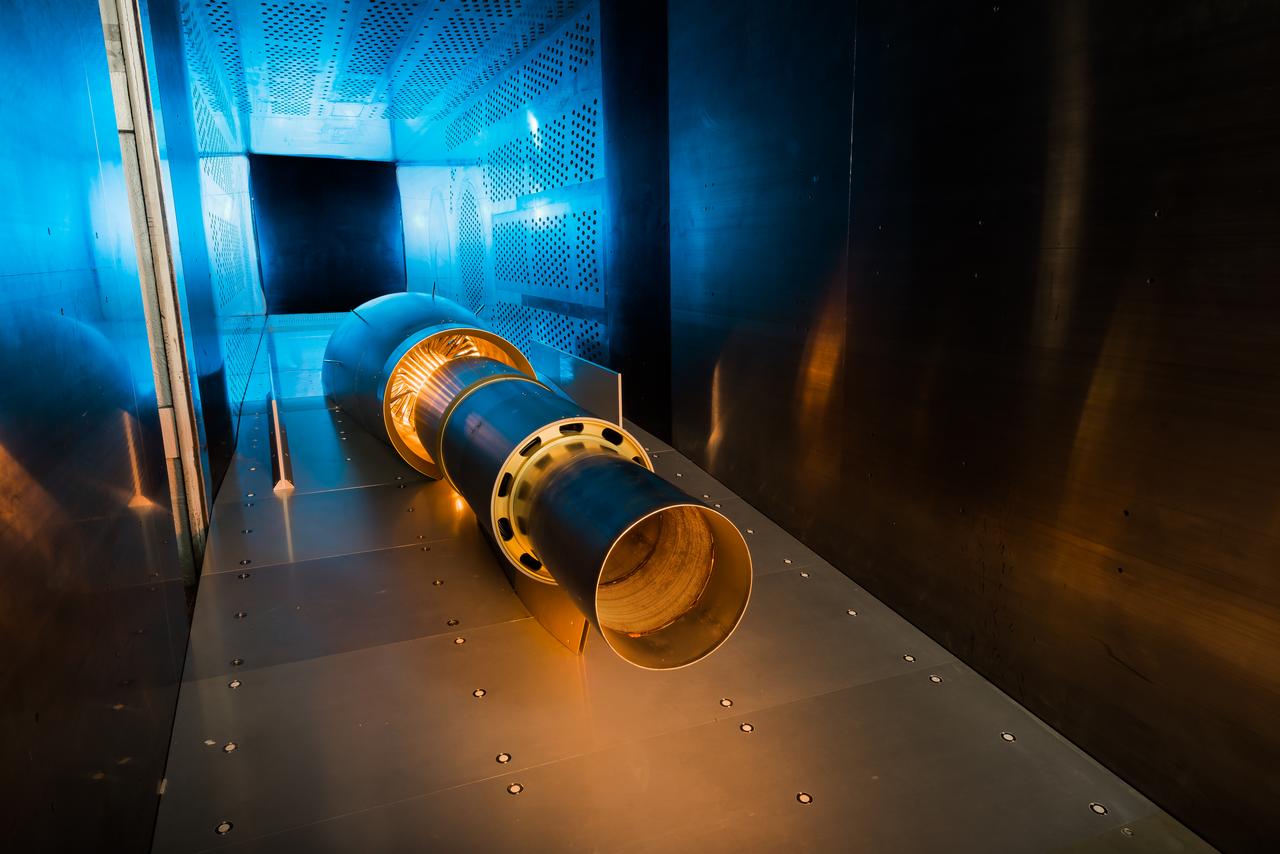
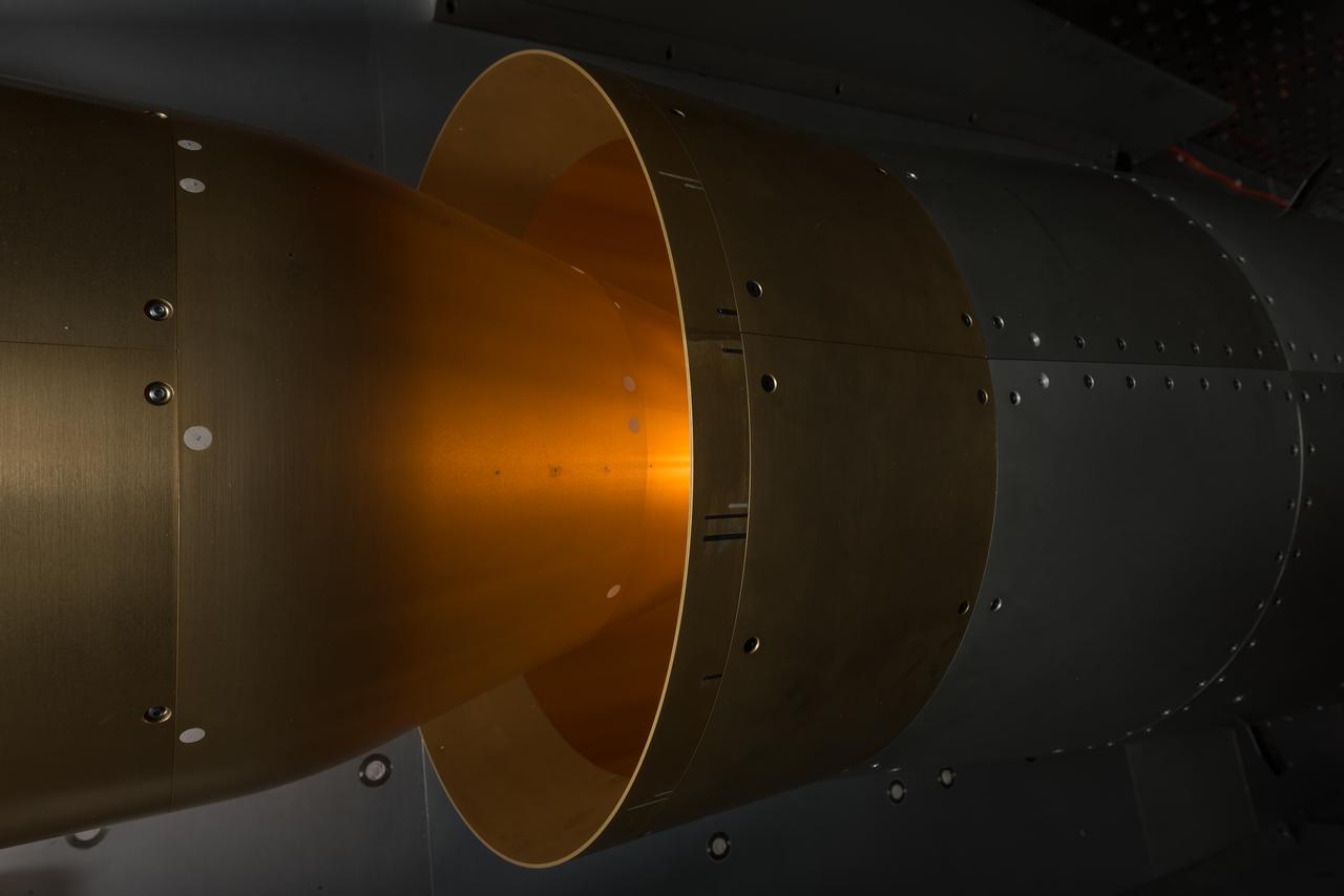
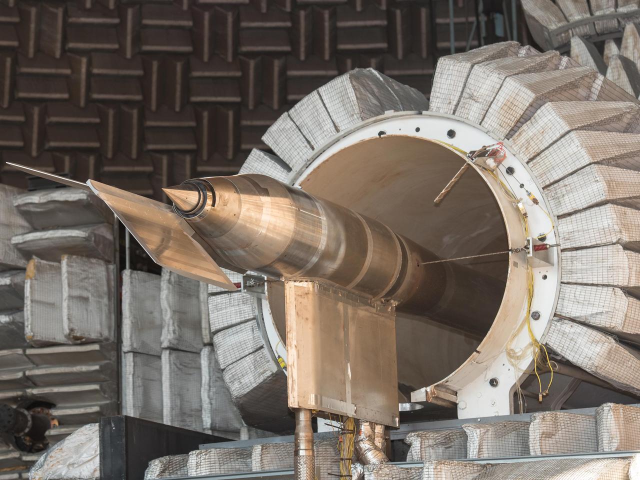
N+2 Nozzle in the Aero-Acoustic Propulsion Lab. As NASA works toward demonstrating low-sonic boom design, engineers at NASA Glenn have tested an engine nozzle that could make supersonic aircraft much quieter.
N+2 Nozzle in the Aero-Acoustic Propulsion Lab. As NASA works toward demonstrating low-sonic boom design, engineers at NASA Glenn have tested an engine nozzle that could make supersonic aircraft much quieter.

Administrator award (two) Center-Tracon Automation system Team Langley Res. CTR and Goal Award 1998, Next-Genreation Design Tools and Experimental Aircraft- acrylic
Researchers Robert Cummings, left, and Harold Gold with the small Low Cost Engine in the shadow of the much larger Quiet Engine at the National Aeronautics and Space Administration (NASA) Lewis Research Center. The two engines were being studied in different test cells at the Propulsion Systems Laboratory. Jet engines had proven themselves on military and large transport aircraft, but their use on small general aviation aircraft was precluded by cost. Lewis undertook a multiyear effort to develop a less expensive engine to fill this niche using existing technologies. Lewis researchers designed a four-stage, axial-flow engine constructed from sheet metal. It was only 11.5 inches in diameter and weighed 100 pounds. The final design specifications were turned over to a manufacturer in 1972. Four engines were created, and, as expected, the fabrication and assembly of the engine were comparatively inexpensive. In 1973 the Low Cost Engine had its first realistic analysis in the Propulsion Systems Laboratory altitude tank. The engine successfully operated at speeds up to Mach 1.24 and simulated altitudes of 30,000 feet. NASA released the engine to private industry in the hope that design elements would be incorporated into future projects and reduce the overall cost of small jet aircraft. Small jet and turboprop engines became relatively common in general aviation aircraft by the late 1970s.
A Highly Maneuverable Aircraft Technology (HiMAT) inlet model installed in the test section of the 8- by 6-Foot Supersonic Wind Tunnel at the National Aeronautics and Space Administration (NASA) Lewis Research Center. Engineers at the Ames Research Center, Dryden Flight Research Center, and Rockwell International designed two pilotless subscale HiMAT vehicles in the mid-1970s to study new design concepts for fighter aircraft in the transonic realm without risking the lives of test pilots. The aircraft used sophisticated technologies such as advanced aerodynamics, composite materials, digital integrated propulsion control, and digital fly-by-wire control systems. In late 1977 NASA Lewis studied the HiMAT’s General Electric J85-21 jet engine in the Propulsion Systems Laboratory. The researchers charted the inlet quality with various combinations anti-distortion screens. HiMAT employed a relatively short and curved inlet compared to actual fighter jets. In the spring of 1979, Larry Smith led an in-depth analysis of the HiMAT inlet in the 8- by 6 tunnel. The researchers installed vortex generators to battle flow separation in the diffuser. The two HiMAT aircraft performed 11 hours of flying over the course of 26 missions from mid-1979 to January 1983 at Dryden and Ames. Although the HiMAT vehicles were considered to be overly complex and expensive, the program yielded a wealth of data that would validate computer-based design tools.

VANDENBERG AIR FORCE BASE, CALIF. - The L-1011 carrier aircraft is ready for flight after undergoing a Combined Systems Test, an integrated test involving the Pegasus launch vehicle, SciSat-1 spacecraft and L-1011 aircraft. The SciSat-1 weighs approximately 330 pounds and after launch will be placed in a 400-mile-high polar orbit to investigate processes that control the distribution of ozone in the upper atmosphere. The data from the satellite will provide Canadian and international scientists with improved measurements relating to global ozone processes and help policymakers assess existing environmental policy and develop protective measures for improving the health of our atmosphere, preventing further ozone depletion. The mission is designed to last two years.
NASA’s X-59 undergoes a structural stress test at Lockheed Martin’s facility in Fort Worth, Texas. The X-59’s nose makes up one third of the aircraft, at 38-feet in length. The X-59 is a one-of-a-kind airplane designed to fly at supersonic speeds without making a startling sonic boom sound for the communities below. This is part of NASA’s Quesst mission, which plans to help enable supersonic air travel over land
NASA’s X-59 undergoes a structural stress test at a Lockheed Martin facility in Fort Worth, Texas. The X-59’s nose makes up one third of the aircraft, at 38-feet in length. The X-59 is a one-of-a-kind airplane designed to fly at supersonic speeds without making aa startling sonic boom sound for the communities below. This is part of NASA’s Quesst mission which plans to help enable supersonic air travel over land
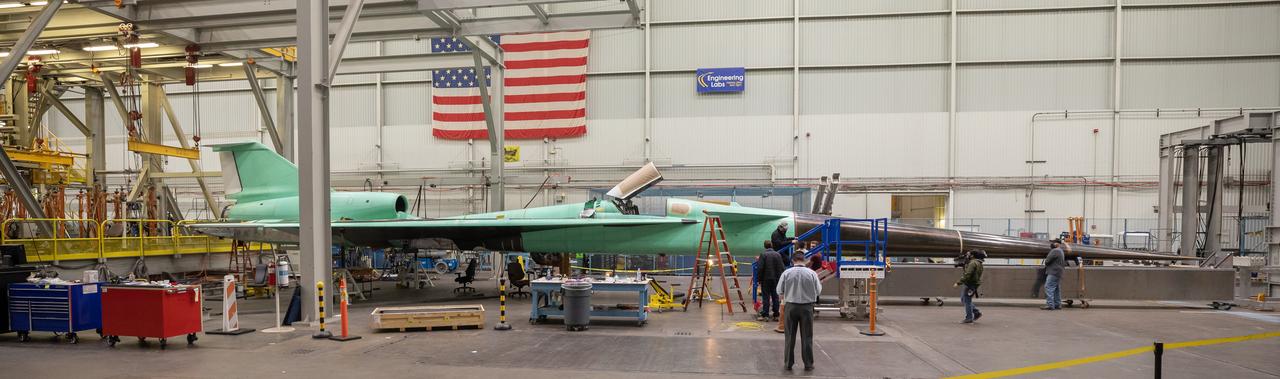
A panoramic view of NASA’s X-59 in Fort Worth, Texas to undergo structural and fuel testing. The X-59’s nose makes up one third of the aircraft, at 38-feet in length. The X-59 is a one-of-a-kind airplane designed to fly at supersonic speeds without making a startling sonic boom sound for the communities below. This is part of NASA’s Quesst mission which plans to help enable supersonic air travel over land.
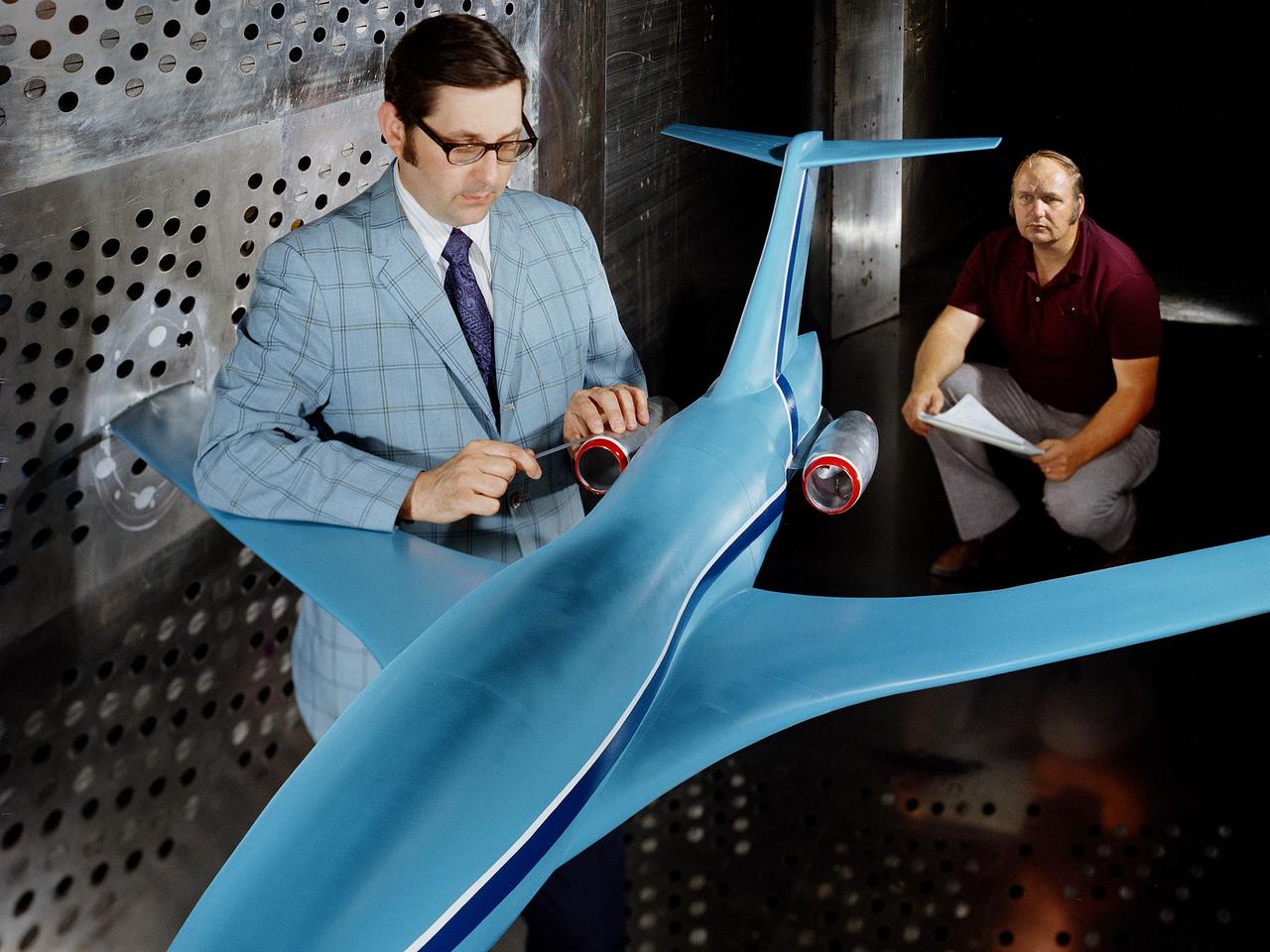
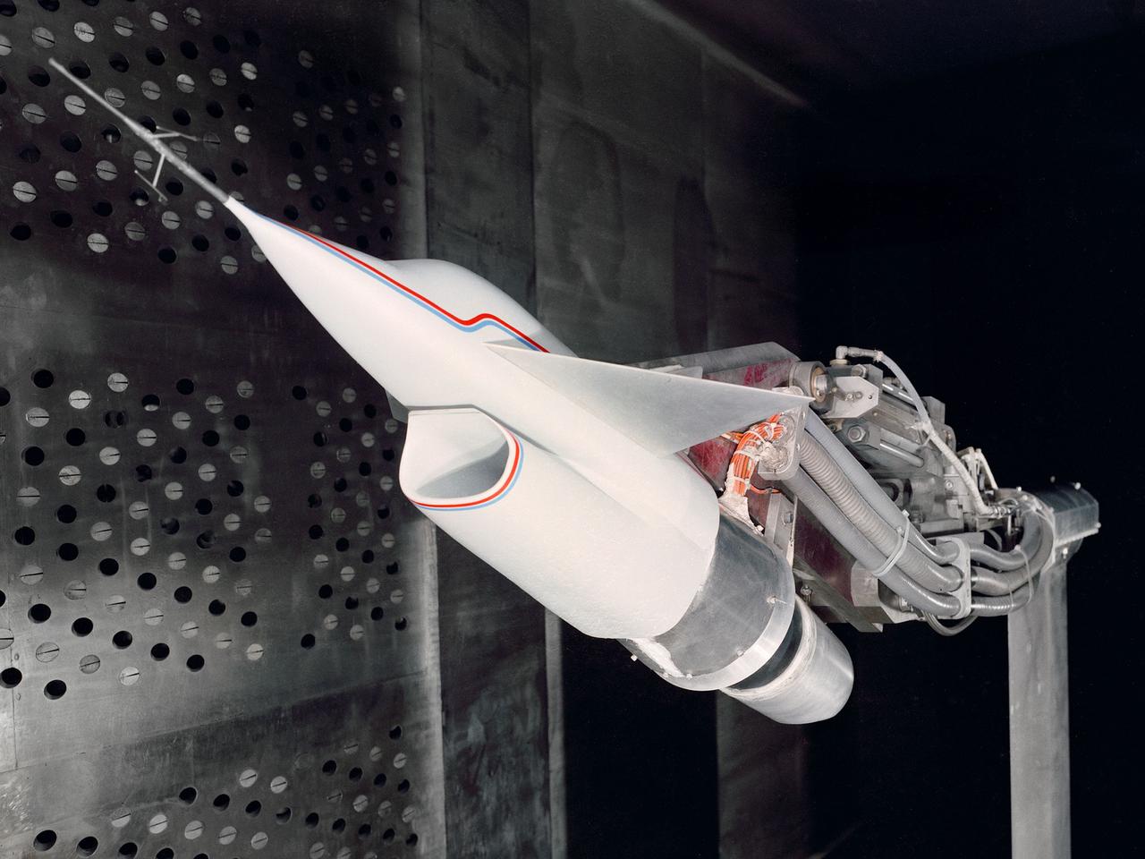
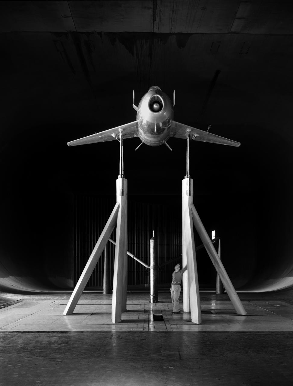
A researcher examines an Advanced Technology Transport model installed in the 8- by 6-Foot Supersonic Wind Tunnel at the National Aeronautics and Space Administration (NASA) Lewis Research Center. The Advanced Technology Transport concept was a 200-person supersonic transport aircraft that could cruise at Mach 0.9 to 0.98 with low noise and pollution outputs. General Electric and Pratt and Whitney responded to NASA Lewis’ call to design a propulsion system for the aircraft. The integration of the propulsion system with the airframe was one of the greatest challenges facing the designers of supersonic aircraft. The aircraft’s flow patterns and engine nacelles could significantly affect the performance of the engines. NASA Lewis researchers undertook a study of this 0.30-scale model of the Advanced Technology Transport in the 8- by 6-foot tunnel. The flow-through nacelles were located near the rear of the fuselage during the initial tests, seen here, and then moved under the wings for ensuing runs. Different engine cowl shapes were also analyzed. The researchers determined that nacelles mounted at the rear of the aircraft produced more efficient airflow patterns during cruising conditions at the desired velocities. The concept of the Advanced Technology Transport, nor any other US supersonic transport, has ever come to fruition. The energy crisis, environmental concerns, and inadequate turbofan technology of the 1970s were among the most significant reasons.
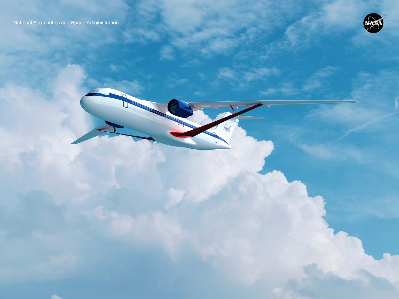
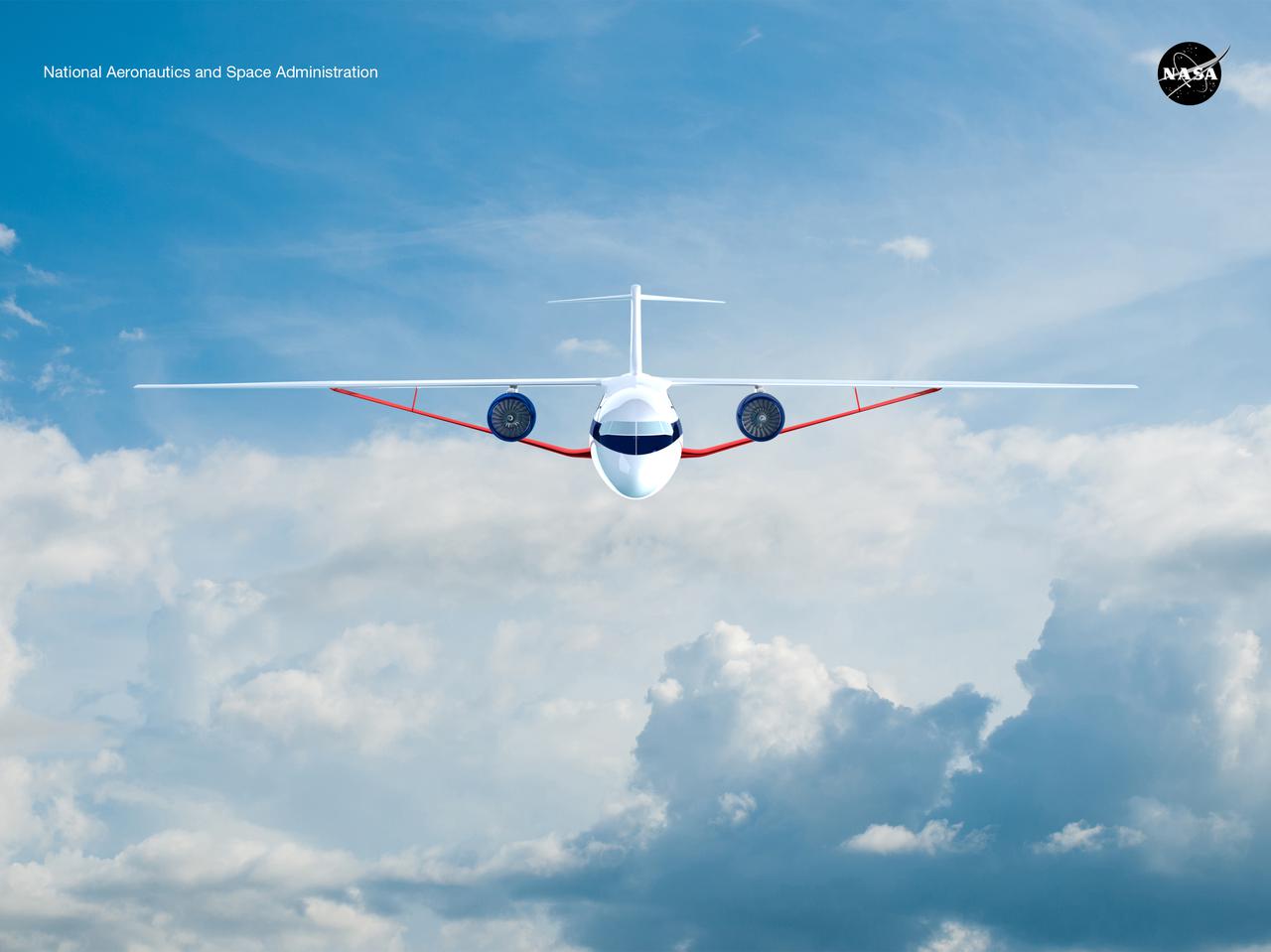
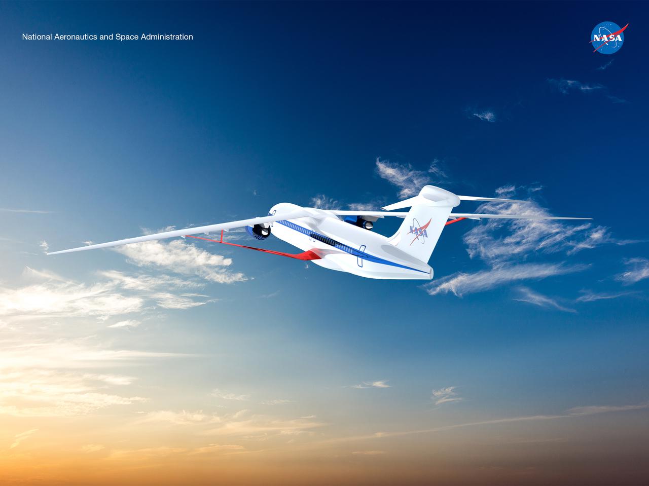
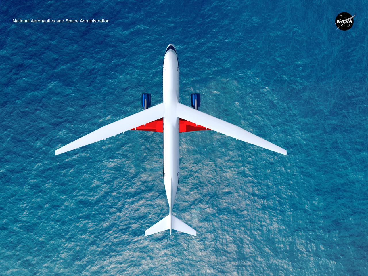
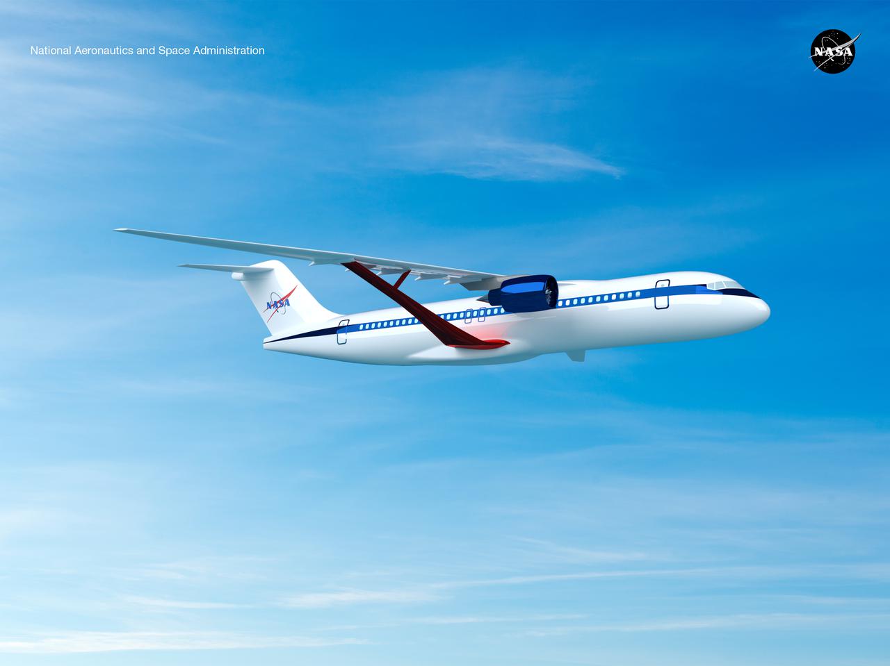
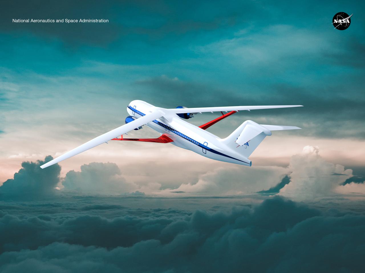
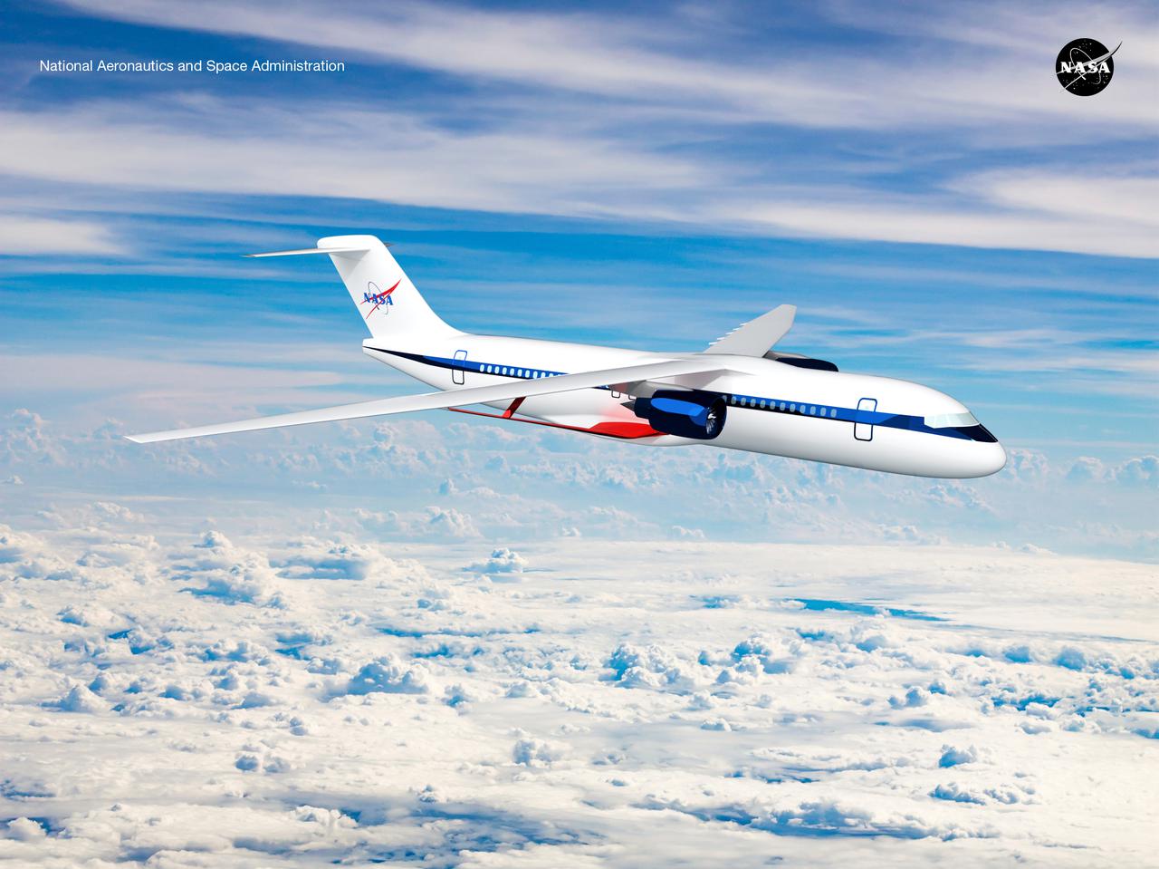
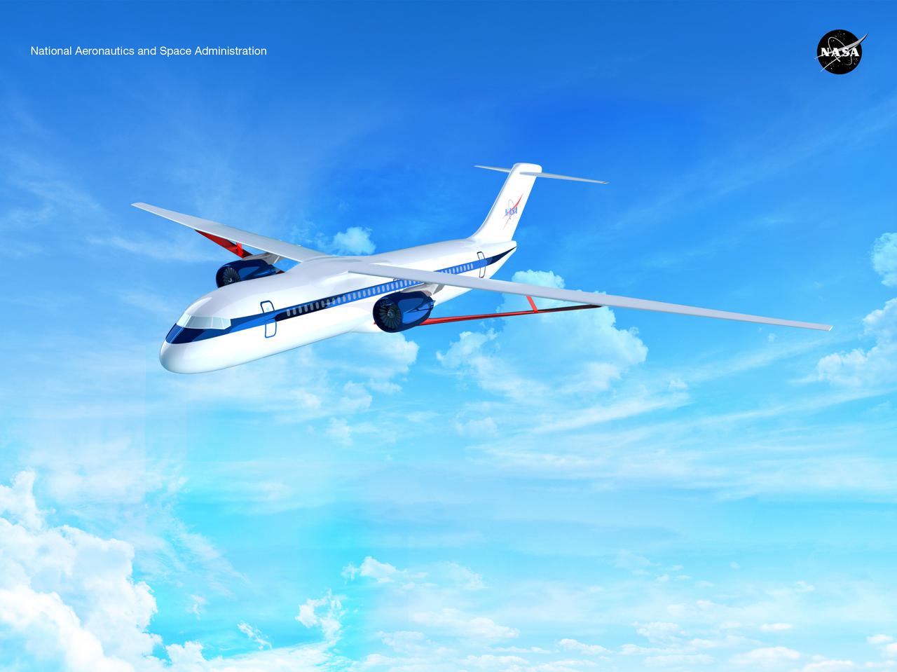
Notice anything different about the wings on this airliner? This conceptual truss-braced wing narrowbody is an aircraft with a 170ft span folding wing. By utilizing trusses, the aircraft can have longer, thinner wings with greater aspect ratios. This, in turn, translates into less drag and 5-10% less fuel burned. The Transonic Truss-Braced Wing aircraft originated from a joint effort by NASA and Boeing to develop subsonic commercial transport concepts – meeting NASA-defined metrics in terms of reduced noise, emissions, and fuel consumption. The design is currently undergoing wind tunnel testing and other studies by NASA researchers.
Derek Abramson, left, chief engineer for the Dale Reed Subscale Flight Research Laboratory, and Justin Link, small unmanned aircraft system pilot, carry the atmospheric probe model and a quad rotor remotely piloted aircraft to position it for flight on Oct. 24, 2024. John Bodylski, probe principal investigator, right, and videographer Jacob Shaw watch the preparations. Once at altitude, the quad rotor aircraft released the probe above Rogers Dry Lake, a flight area adjacent to NASA’s Armstrong Flight Research Center in Edwards, California. The probe was designed and built at the center.
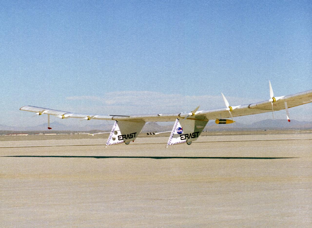
The Pathfinder solar-powered research aircraft settles in for landing on the bed of Rogers Dry Lake at the Dryden Flight Research Center, Edwards, California, after a successful test flight Nov. 19, 1996. The ultra-light craft flew a racetrack pattern at low altitudes over the flight test area for two hours while project engineers checked out various systems and sensors on the uninhabited aircraft. The Pathfinder was controlled by two pilots, one in a mobile control unit which followed the craft, the other in a stationary control station. Pathfinder, developed by AeroVironment, Inc., is one of several designs being evaluated under NASA's Environmental Research Aircraft and Sensor Technology (ERAST) program.
Notice anything different about the wings on this airliner? This conceptual truss-braced wing narrowbody is an aircraft with a 170ft span folding wing. By utilizing trusses, the aircraft can have longer, thinner wings with greater aspect ratios. This, in turn, translates into less drag and 5-10% less fuel burned. The Transonic Truss-Braced Wing aircraft originated from a joint effort by NASA and Boeing to develop subsonic commercial transport concepts – meeting NASA-defined metrics in terms of reduced noise, emissions, and fuel consumption. The design is currently undergoing wind tunnel testing and other studies by NASA researchers.
Notice anything different about the wings on this airliner? This conceptual truss-braced wing narrowbody is an aircraft with a 170ft span folding wing. By utilizing trusses, the aircraft can have longer, thinner wings with greater aspect ratios. This, in turn, translates into less drag and 5-10% less fuel burned. The Transonic Truss-Braced Wing aircraft originated from a joint effort by NASA and Boeing to develop subsonic commercial transport concepts – meeting NASA-defined metrics in terms of reduced noise, emissions, and fuel consumption. The design is currently undergoing wind tunnel testing and other studies by NASA researchers.
Notice anything different about the wings on this airliner? This conceptual truss-braced wing narrowbody is an aircraft with a 170ft span folding wing. By utilizing trusses, the aircraft can have longer, thinner wings with greater aspect ratios. This, in turn, translates into less drag and 5-10% less fuel burned. The Transonic Truss-Braced Wing aircraft originated from a joint effort by NASA and Boeing to develop subsonic commercial transport concepts – meeting NASA-defined metrics in terms of reduced noise, emissions, and fuel consumption. The design is currently undergoing wind tunnel testing and other studies by NASA researchers.
Notice anything different about the wings on this airliner? This conceptual truss-braced wing narrowbody is an aircraft with a 170ft span folding wing. By utilizing trusses, the aircraft can have longer, thinner wings with greater aspect ratios. This, in turn, translates into less drag and 5-10% less fuel burned. The Transonic Truss-Braced Wing aircraft originated from a joint effort by NASA and Boeing to develop subsonic commercial transport concepts – meeting NASA-defined metrics in terms of reduced noise, emissions, and fuel consumption. The design is currently undergoing wind tunnel testing and other studies by NASA researchers.
Notice anything different about the wings on this airliner? This conceptual truss-braced wing narrowbody is an aircraft with a 170ft span folding wing. By utilizing trusses, the aircraft can have longer, thinner wings with greater aspect ratios. This, in turn, translates into less drag and 5-10% less fuel burned. The Transonic Truss-Braced Wing aircraft originated from a joint effort by NASA and Boeing to develop subsonic commercial transport concepts – meeting NASA-defined metrics in terms of reduced noise, emissions, and fuel consumption. The design is currently undergoing wind tunnel testing and other studies by NASA researchers.
Notice anything different about the wings on this airliner? This conceptual truss-braced wing narrowbody is an aircraft with a 170ft span folding wing. By utilizing trusses, the aircraft can have longer, thinner wings with greater aspect ratios. This, in turn, translates into less drag and 5-10% less fuel burned. The Transonic Truss-Braced Wing aircraft originated from a joint effort by NASA and Boeing to develop subsonic commercial transport concepts – meeting NASA-defined metrics in terms of reduced noise, emissions, and fuel consumption. The design is currently undergoing wind tunnel testing and other studies by NASA researchers.
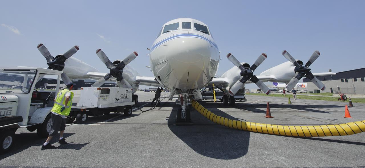
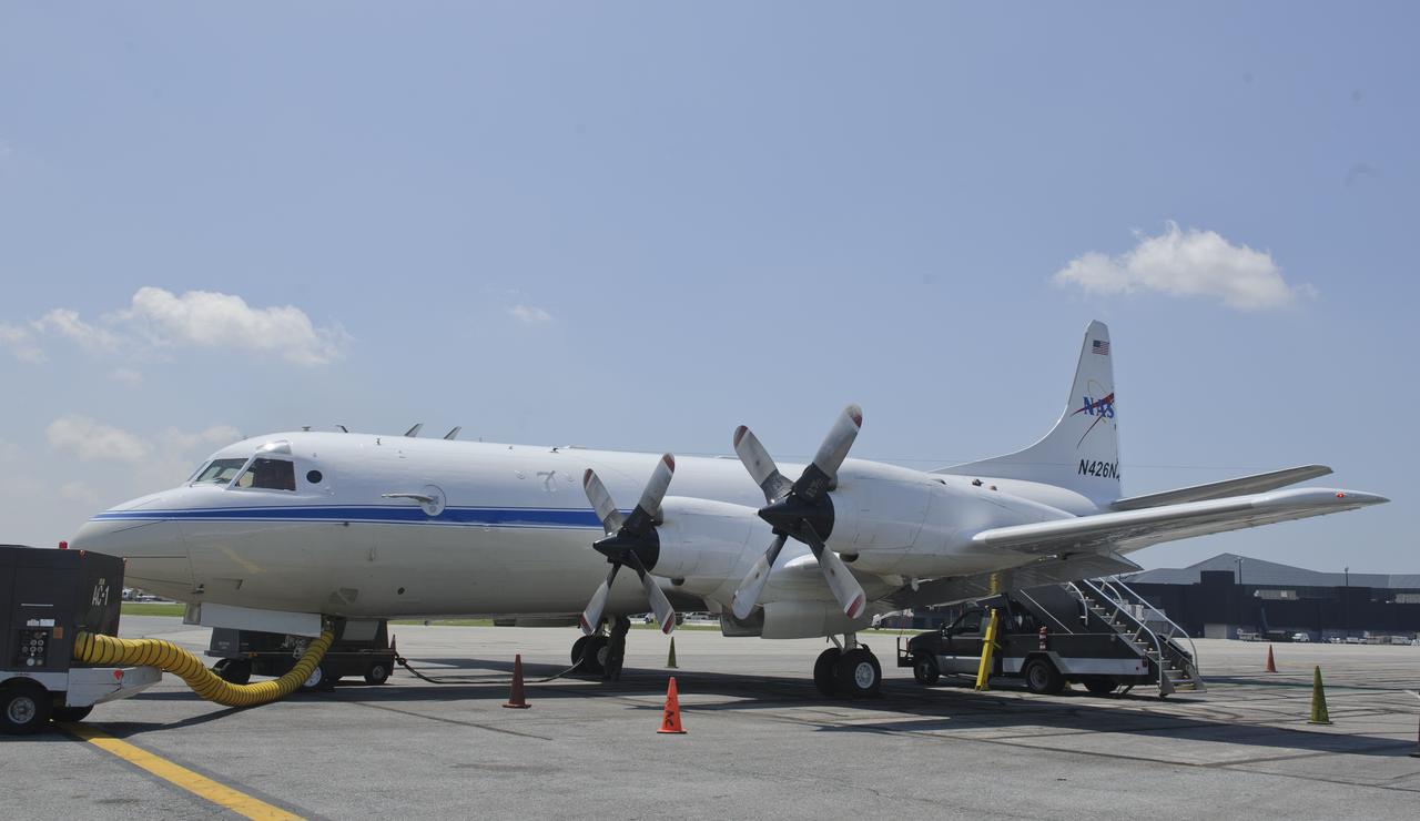
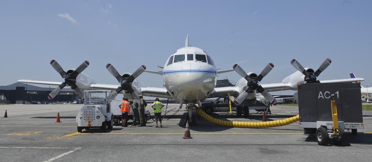
A 117-foot P-3B NASA research aircraft is seen on the tarmac at Baltimore/Washington International Thurgood Marshall Airport, Tuesday, June 28, 2011, in Baltimore, Md. The aircraft is part of a month-long field campaign designed to improve satellite measurements of air pollution. The name of the experiment -- Deriving Information on Surface conditions from Column and Vertically Resolved Observations Relevant to Air Quality (DISCOVER -- AQ) -- is a mouthful, but its purpose is simple. Come July, the aircraft will be flying spirals over six ground stations in Maryland. Photo Credit: (NASA/Paul E. Alers)
Notice anything different about the wings on this airliner? This conceptual truss-braced wing narrowbody is an aircraft with a 170ft span folding wing. By utilizing trusses, the aircraft can have longer, thinner wings with greater aspect ratios. This, in turn, translates into less drag and 5-10% less fuel burned. The Transonic Truss-Braced Wing aircraft originated from a joint effort by NASA and Boeing to develop subsonic commercial transport concepts – meeting NASA-defined metrics in terms of reduced noise, emissions, and fuel consumption. The design is currently undergoing wind tunnel testing and other studies by NASA researchers.
Notice anything different about the wings on this airliner? This conceptual truss-braced wing narrowbody is an aircraft with a 170ft span folding wing. By utilizing trusses, the aircraft can have longer, thinner wings with greater aspect ratios. This, in turn, translates into less drag and 5-10% less fuel burned. The Transonic Truss-Braced Wing aircraft originated from a joint effort by NASA and Boeing to develop subsonic commercial transport concepts – meeting NASA-defined metrics in terms of reduced noise, emissions, and fuel consumption. The design is currently undergoing wind tunnel testing and other studies by NASA researchers.
Long, thin, high-aspect-ratio wings are considered crucial to the design of future long-range aircraft, including fuel-efficient airliners and cargo transports. Unlike the short, stiff wings found on most aircraft today, slender, flexible airfoils are susceptible to uncontrollable vibrations, known as flutter, and may be stressed by bending forces from wind gusts and atmospheric turbulence. To improve ride quality, efficiency, safety, and the long-term health of flexible aircraft structures, NASA is using the X-56A Multi-Utility Technology Testbed (MUTT) to investigate key technologies for active flutter suppression and gust-load alleviation.
Notice anything different about the wings on this airliner? This conceptual truss-braced wing narrowbody is an aircraft with a 170ft span folding wing. By utilizing trusses, the aircraft can have longer, thinner wings with greater aspect ratios. This, in turn, translates into less drag and 5-10% less fuel burned. The Transonic Truss-Braced Wing aircraft originated from a joint effort by NASA and Boeing to develop subsonic commercial transport concepts – meeting NASA-defined metrics in terms of reduced noise, emissions, and fuel consumption. The design is currently undergoing wind tunnel testing and other studies by NASA researchers.
Notice anything different about the wings on this airliner? This conceptual truss-braced wing narrowbody is an aircraft with a 170ft span folding wing. By utilizing trusses, the aircraft can have longer, thinner wings with greater aspect ratios. This, in turn, translates into less drag and 5-10% less fuel burned. The Transonic Truss-Braced Wing aircraft originated from a joint effort by NASA and Boeing to develop subsonic commercial transport concepts – meeting NASA-defined metrics in terms of reduced noise, emissions, and fuel consumption. The design is currently undergoing wind tunnel testing and other studies by NASA researchers.

A 117-foot P-3B NASA research aircraft is seen on the tarmac at Baltimore/Washington International Thurgood Marshall Airport, Tuesday, June 28, 2011, in Baltimore, Md. The aircraft is part of a month-long field campaign designed to improve satellite measurements of air pollution. The name of the experiment -- Deriving Information on Surface conditions from Column and Vertically Resolved Observations Relevant to Air Quality (DISCOVER -- AQ) -- is a mouthful, but its purpose is simple. Come July, the aircraft will be flying spirals over six ground stations in Maryland. Photo Credit: (NASA/Paul E. Alers)
Front View of McDonald XP-85 Plan Model. Parasite Airplane designed to be carried in the B-36 bombay (never built) At the time it was the smallest Jet powered airplane. The McDonnell XF-85 Goblin was an American prototype fighter aircraft conceived during World War II by McDonnell Aircraft. It was intended to be deployed from the bomb bay of the giant Convair B-36 bomber as a parasite fighter. The XF-85's intended role was to defend bombers from hostile interceptor aircraft, a need demonstrated during World War II
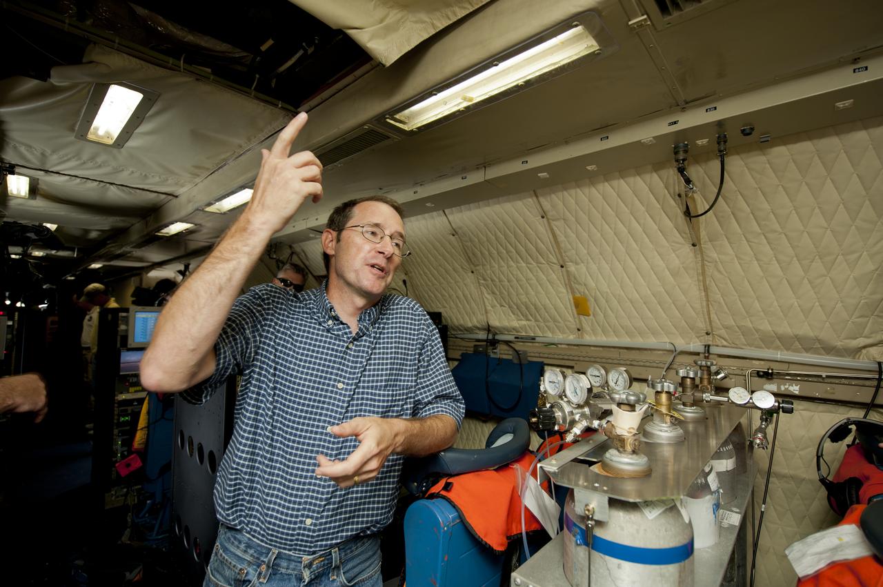
James Crawford, principal investigator and scientist based at NASA’s Langley Research Center in Hampton, Va., talks about the DISCOVER-AQ project on board the P-3B NASA research aircraft at Baltimore/Washington International Thurgood Marshall Airport, Tuesday, June 28, 2011, in Baltimore, Md. The aircraft is part of a month-long field campaign designed to improve satellite measurements of air pollution. The name of the experiment -- Deriving Information on Surface conditions from Column and Vertically Resolved Observations Relevant to Air Quality (DISCOVER -- AQ) -- is a mouthful, but its purpose is simple. Come July, the aircraft will be flying spirals over six ground stations in Maryland. Photo Credit: (NASA/Paul E. Alers)
Notice anything different about the wings on this airliner? This conceptual truss-braced wing narrowbody is an aircraft with a 170ft span folding wing. By utilizing trusses, the aircraft can have longer, thinner wings with greater aspect ratios. This, in turn, translates into less drag and 5-10% less fuel burned. The Transonic Truss-Braced Wing aircraft originated from a joint effort by NASA and Boeing to develop subsonic commercial transport concepts – meeting NASA-defined metrics in terms of reduced noise, emissions, and fuel consumption. The design is currently undergoing wind tunnel testing and other studies by NASA researchers.
Notice anything different about the wings on this airliner? This conceptual truss-braced wing narrowbody is an aircraft with a 170ft span folding wing. By utilizing trusses, the aircraft can have longer, thinner wings with greater aspect ratios. This, in turn, translates into less drag and 5-10% less fuel burned. The Transonic Truss-Braced Wing aircraft originated from a joint effort by NASA and Boeing to develop subsonic commercial transport concepts – meeting NASA-defined metrics in terms of reduced noise, emissions, and fuel consumption. The design is currently undergoing wind tunnel testing and other studies by NASA researchers.
Notice anything different about the wings on this airliner? This conceptual truss-braced wing narrowbody is an aircraft with a 170ft span folding wing. By utilizing trusses, the aircraft can have longer, thinner wings with greater aspect ratios. This, in turn, translates into less drag and 5-10% less fuel burned. The Transonic Truss-Braced Wing aircraft originated from a joint effort by NASA and Boeing to develop subsonic commercial transport concepts – meeting NASA-defined metrics in terms of reduced noise, emissions, and fuel consumption. The design is currently undergoing wind tunnel testing and other studies by NASA researchers.
A 117-foot P-3B NASA research aircraft is seen on the tarmac at Baltimore/Washington International Thurgood Marshall Airport, Tuesday, June 28, 2011, in Baltimore, Md. The aircraft is part of a month-long field campaign designed to improve satellite measurements of air pollution. The name of the experiment -- Deriving Information on Surface conditions from Column and Vertically Resolved Observations Relevant to Air Quality (DISCOVER -- AQ) -- is a mouthful, but its purpose is simple. Come July, the aircraft will be flying spirals over six ground stations in Maryland. Photo Credit: (NASA/Paul E. Alers)
A 117-foot P-3B NASA research aircraft is seen on the tarmac at Baltimore/Washington International Thurgood Marshall Airport, Tuesday, June 28, 2011, in Baltimore, Md. The aircraft is part of a month-long field campaign designed to improve satellite measurements of air pollution. The name of the experiment -- Deriving Information on Surface conditions from Column and Vertically Resolved Observations Relevant to Air Quality (DISCOVER -- AQ) -- is a mouthful, but its purpose is simple. Come July, the aircraft will be flying spirals over six ground stations in Maryland. Photo Credit: (NASA/Paul E. Alers)
Notice anything different about the wings on this airliner? This conceptual truss-braced wing narrowbody is an aircraft with a 170ft span folding wing. By utilizing trusses, the aircraft can have longer, thinner wings with greater aspect ratios. This, in turn, translates into less drag and 5-10% less fuel burned. The Transonic Truss-Braced Wing aircraft originated from a joint effort by NASA and Boeing to develop subsonic commercial transport concepts – meeting NASA-defined metrics in terms of reduced noise, emissions, and fuel consumption. The design is currently undergoing wind tunnel testing and other studies by NASA researchers.
Notice anything different about the wings on this airliner? This conceptual truss-braced wing narrowbody is an aircraft with a 170ft span folding wing. By utilizing trusses, the aircraft can have longer, thinner wings with greater aspect ratios. This, in turn, translates into less drag and 5-10% less fuel burned. The Transonic Truss-Braced Wing aircraft originated from a joint effort by NASA and Boeing to develop subsonic commercial transport concepts – meeting NASA-defined metrics in terms of reduced noise, emissions, and fuel consumption. The design is currently undergoing wind tunnel testing and other studies by NASA researchers.
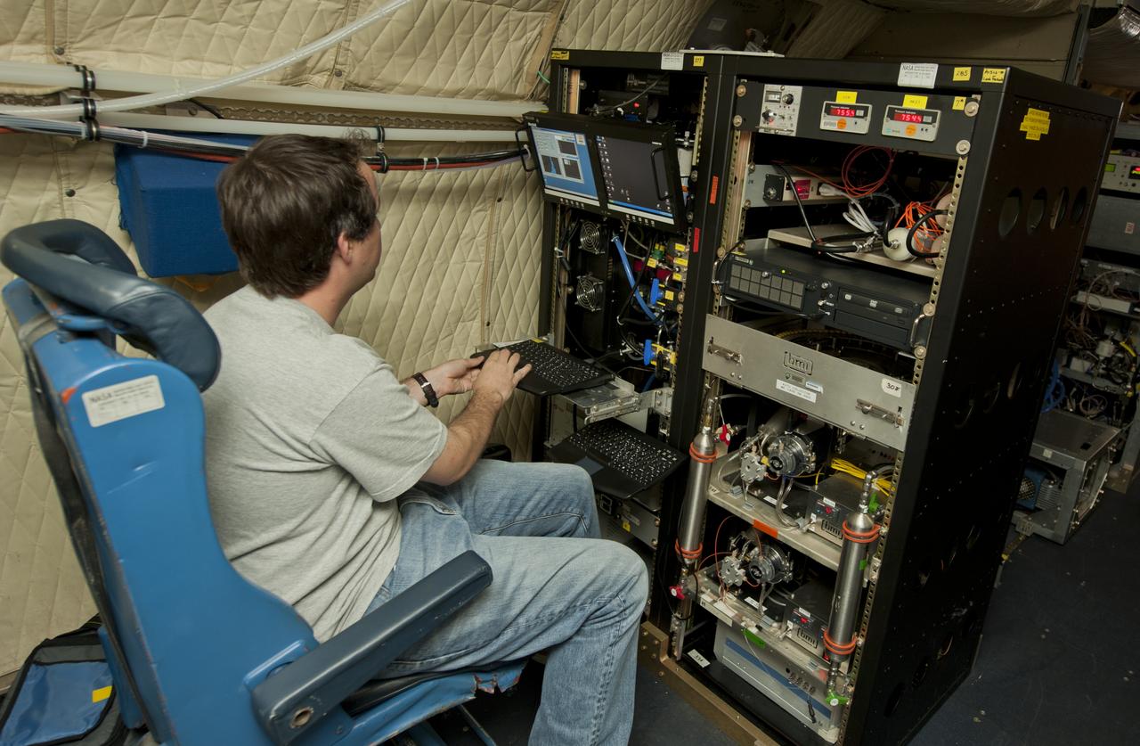
An unidentified researcher works aboard the P-3B NASA research aircraft at Baltimore/Washington International Thurgood Marshall Airport, Tuesday, June 28, 2011, in Baltimore, Md. The aircraft is part of a month-long field campaign designed to improve satellite measurements of air pollution. The name of the experiment -- Deriving Information on Surface conditions from Column and Vertically Resolved Observations Relevant to Air Quality (DISCOVER -- AQ) -- is a mouthful, but its purpose is simple. Come July, the aircraft will be flying spirals over six ground stations in Maryland. Photo Credit: (NASA/Paul E. Alers)