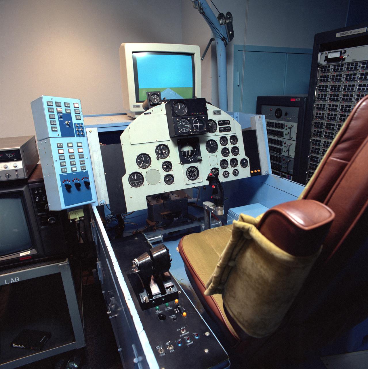
F-15 Propulsion Controlled Aircraft (PCA) simulation cockpit

A simple sketch on a TWA napkin by NASA Dryden engineer Frank W. "Bill" Burcham led to development and validation of the Propulsion-Controlled Aircraft concept.
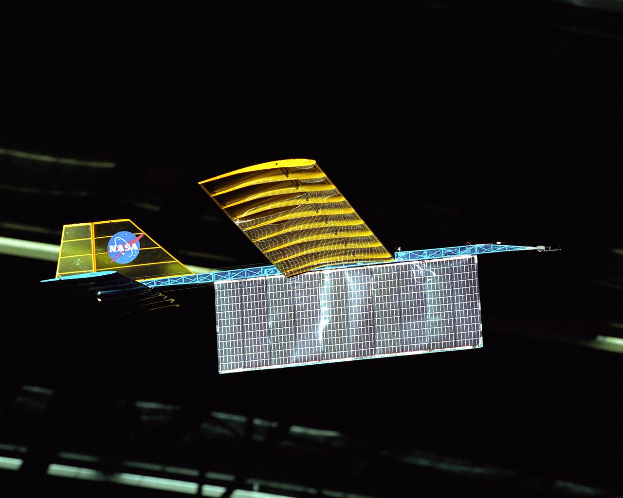
An experimental radio-controlled model aircraft is seen here in flight, powered only by light energy beamed to it by a spotlight.
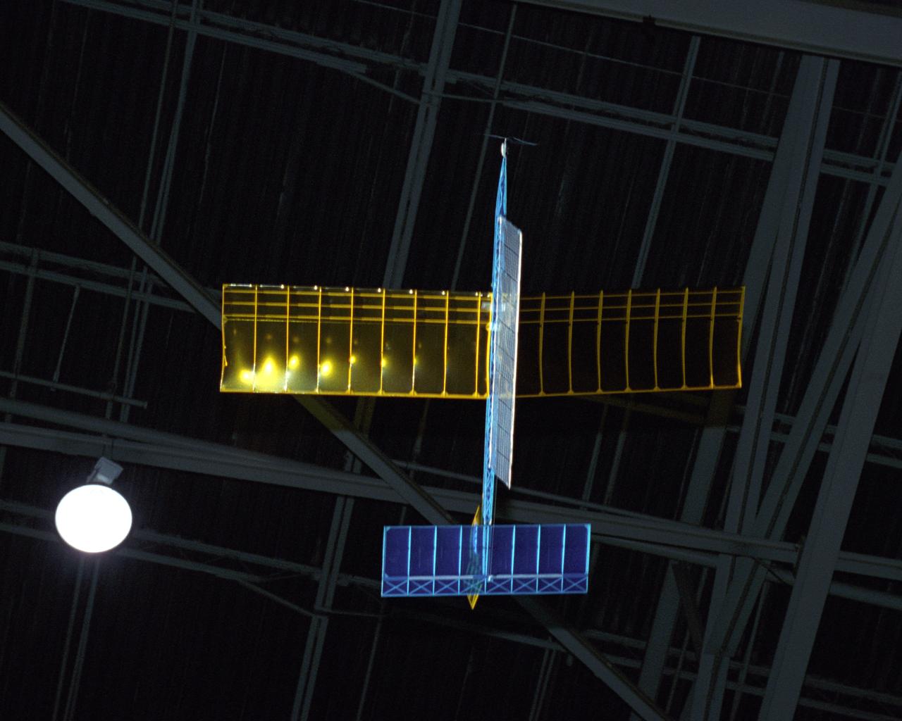
An experimental radio-controlled model aircraft is seen here in flight powered only by light energy beamed to it by a spotlight.

An experimental radio-controlled model aircraft is seen here in flight powered only by light energy beamed to it by a spotlight.
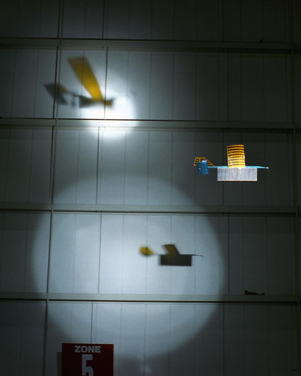
An experimental radio-controlled model aircraft casts two unique shadows as it flies inside a Dryden hangar using two spotlights as energy sources. This phase of testing was used to develop procedures and operations for "handing off" the aircraft between different sources of power.
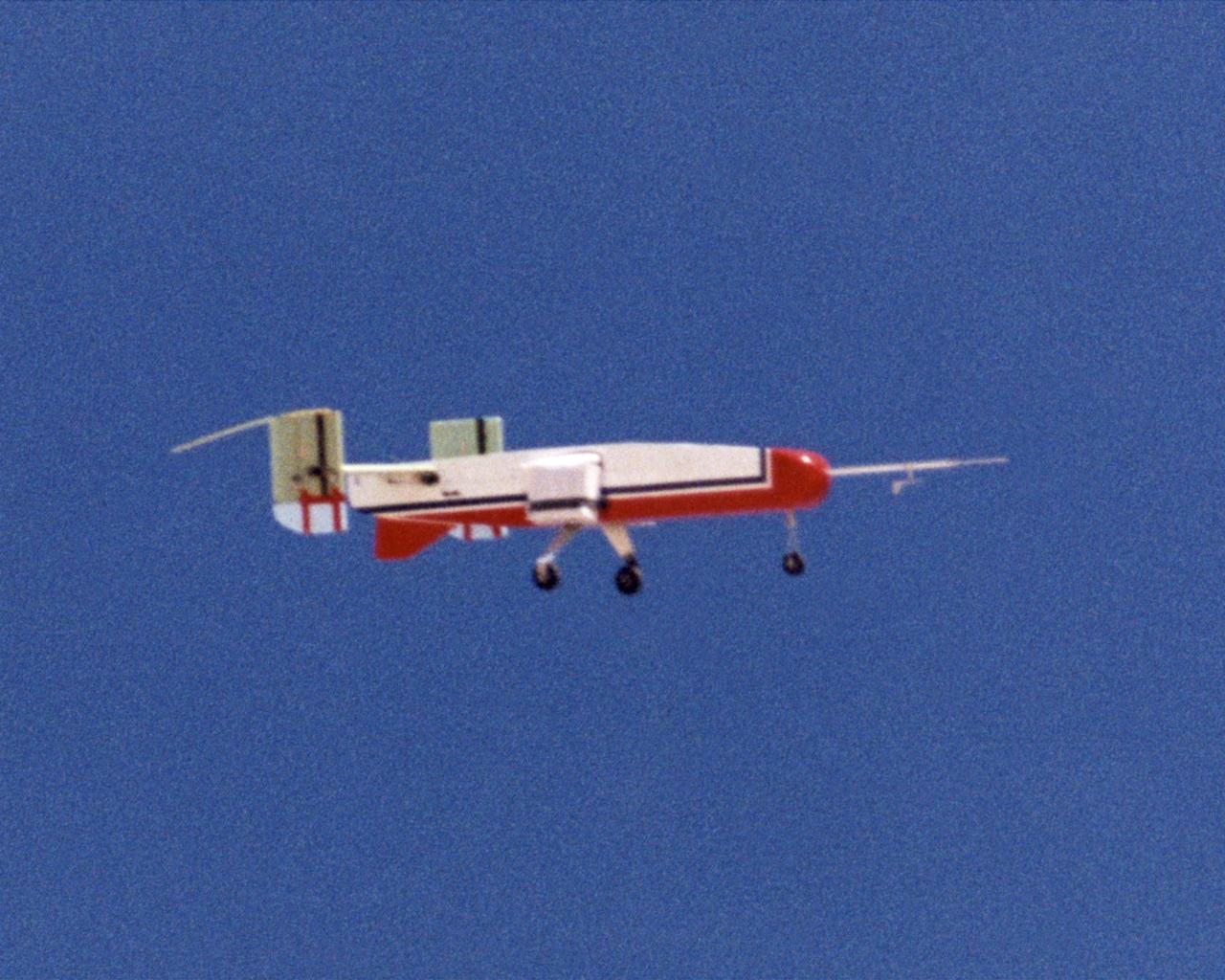
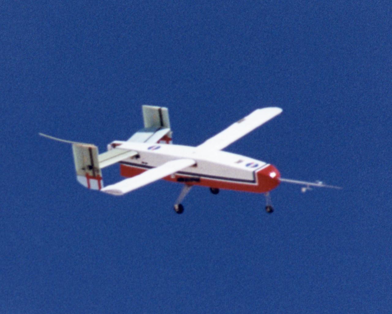
The deployable, inflatable wing technology demonstrator experiment aircraft maintains a steady attitude following separation from its carrier aircraft during a flight conducted by the NASA Dryden Flight Research Center, Edwards, California. The inflatable wing project represented a basic flight research effort by Dryden personnel. Three successful flights of the I2000 inflatable wing aircraft occurred. During the flights, the team air-launched the radio-controlled (R/C) I2000 from an R/C utility airplane at an altitude of 800-1000 feet. As the I2000 separated from the carrier aircraft, its inflatable wings "popped-out," deploying rapidly via an on-board nitrogen bottle. The aircraft remained stable as it transitioned from wingless to winged flight. The unpowered I2000 glided down to a smooth landing under complete control.
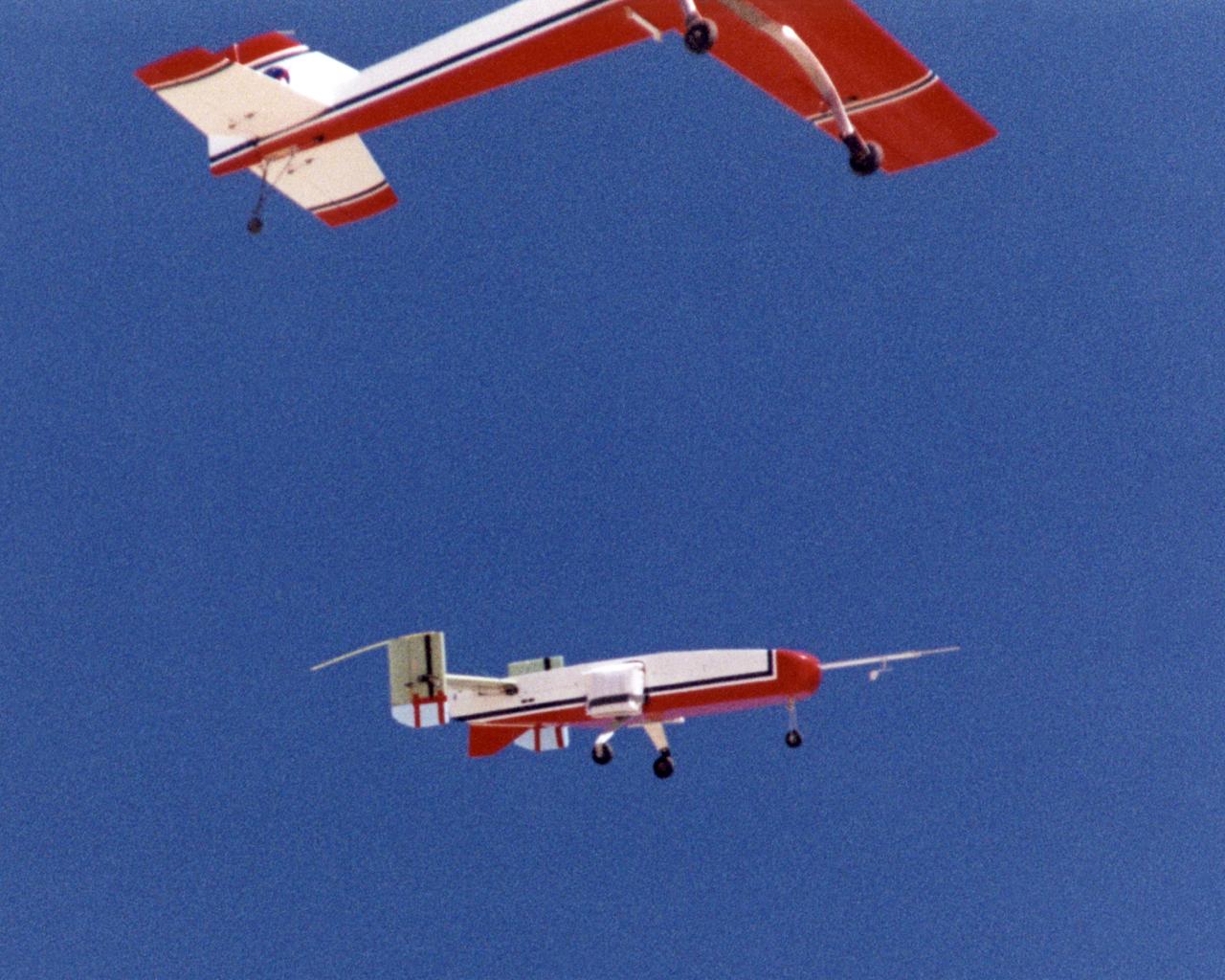
The deployable, inflatable wing technology demonstrator experiment separates from its carrier aircraft during a flight conducted by the NASA Dryden Flight Research Center, Edwards, California. The inflatable wing project represented a basic flight research effort by Dryden personnel. Three successful flights of the I2000 inflatable wing aircraft occurred. During the flights, the team air-launched the radio-controlled (R/C) I2000 from an R/C utility airplane at an altitude of 800-1000 feet. As the I2000 separated from the carrier aircraft, its inflatable wings "popped-out," deploying rapidly via an on-board nitrogen bottle. The aircraft remained stable as it transitioned from wingless to winged flight. The unpowered I2000 glided down to a smooth landing under complete control.

CID (Controlled Imact Demonstrator) Aircraft lakebed skid.

CID (Controlled Imact Demonstrator) Aircraft skid after wing cutter impact.

CID (Controlled Imact Demonstrator) Aircraft fireball after wing cutter impact.

CID (Controlled Imact Demonstrator) Aircraft fireball after wing cutter impact.
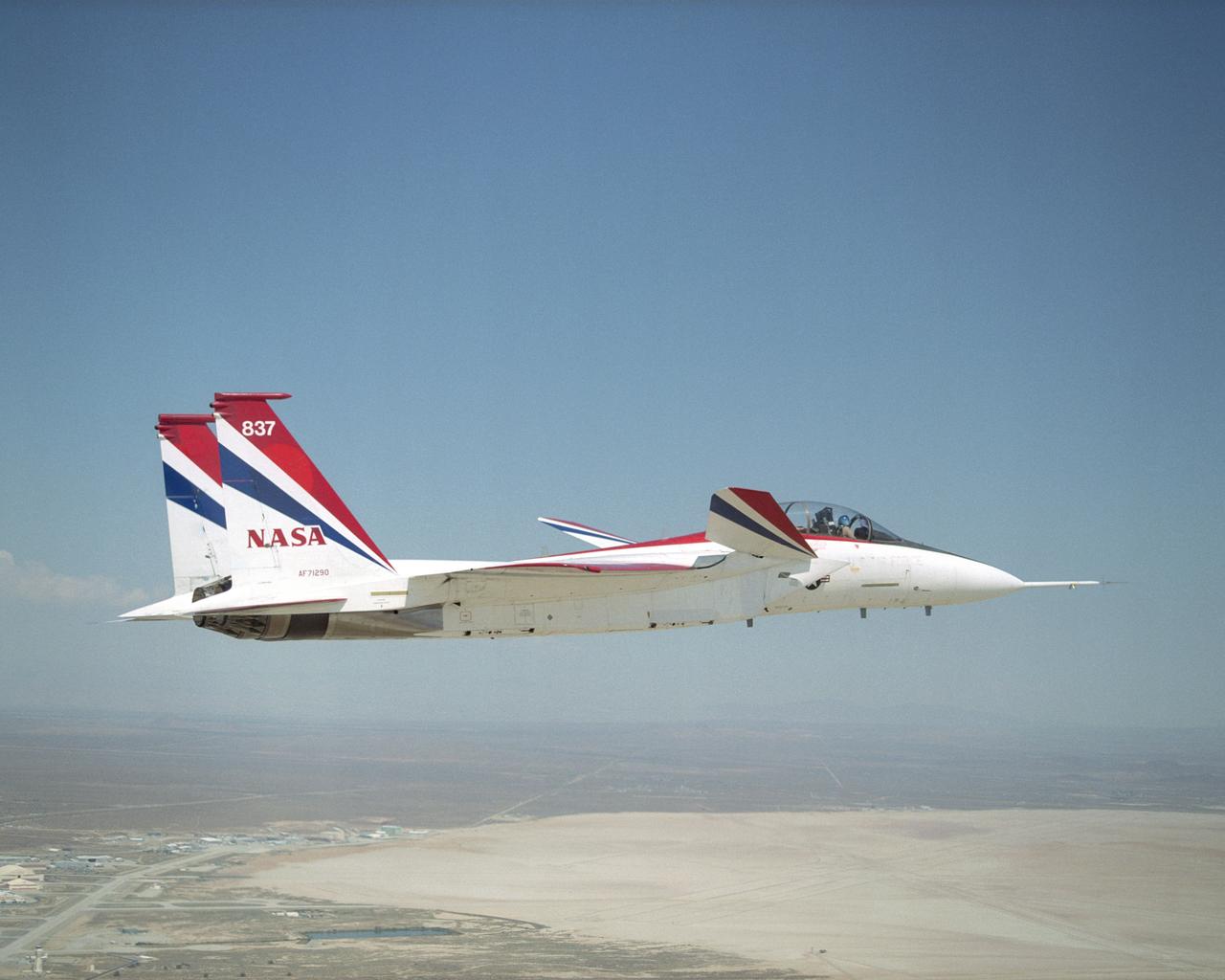
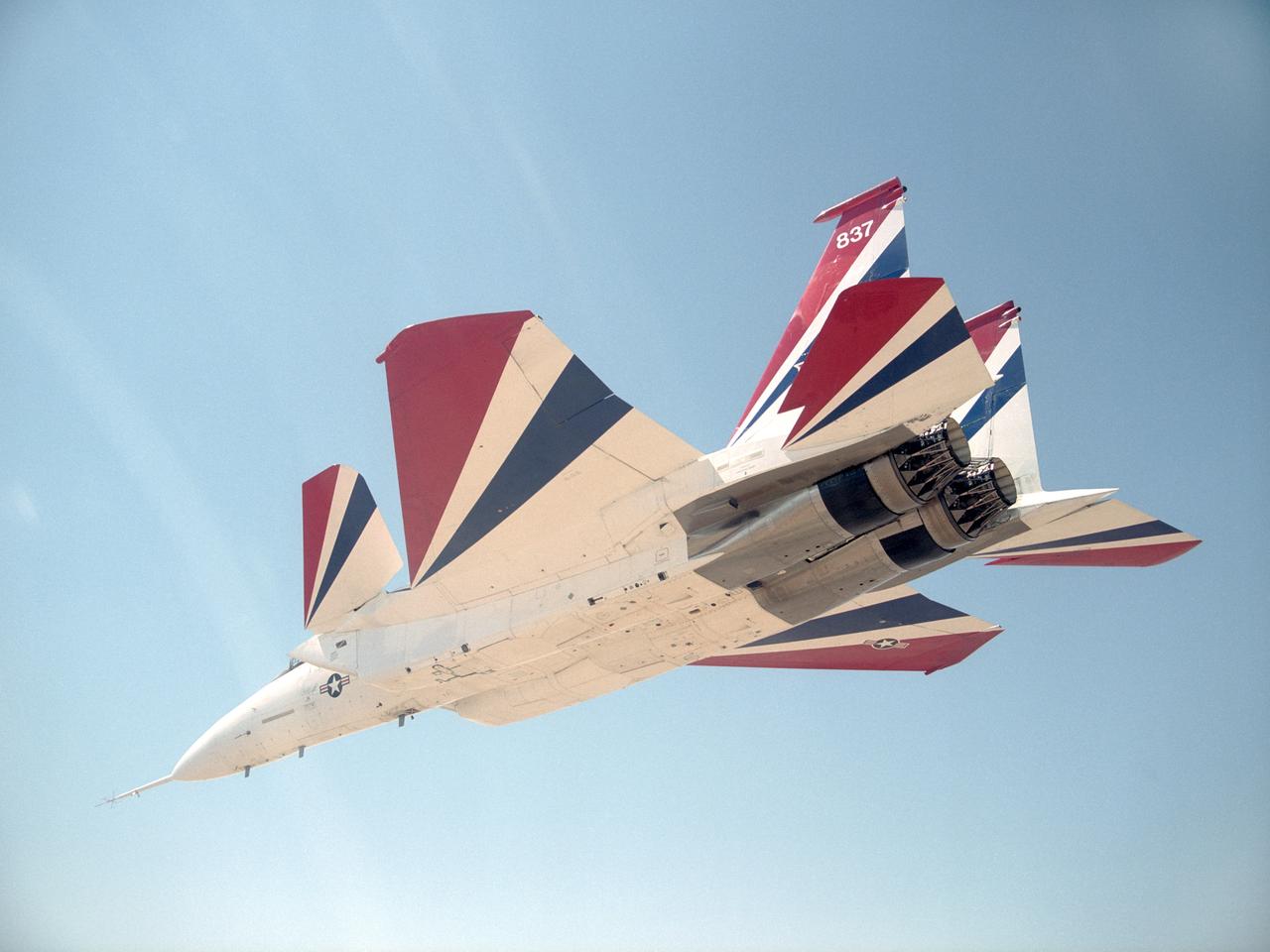
NASA Dryden's highly modified F-15B aircraft, tail number 837, serves as an Intelligent flight Control System (IFCS) research testbed aircraft.

NASA Dryden's highly modified F-15B aircraft, tail number 837, serves as an Intelligent flight Control System (IFCS) research testbed aircraft.
NASA Dryden's highly modified F-15B aircraft, tail number 837, serves as an Intelligent flight Control System (IFCS) research testbed aircraft.

NASA Dryden's highly modified F-15B aircraft, tail number 837, serves as an Intelligent flight Control System (IFCS) research testbed aircraft.

CID (Controlled Imact Demonstrator) Aircraft in practice flight above target impact site with wing cutters.

CID (Controlled Imact Demonstrator) Aircraft prior to wing cutter impact during lakebed skid.

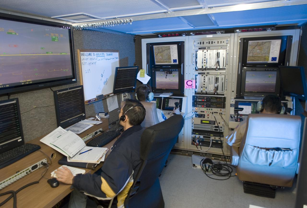
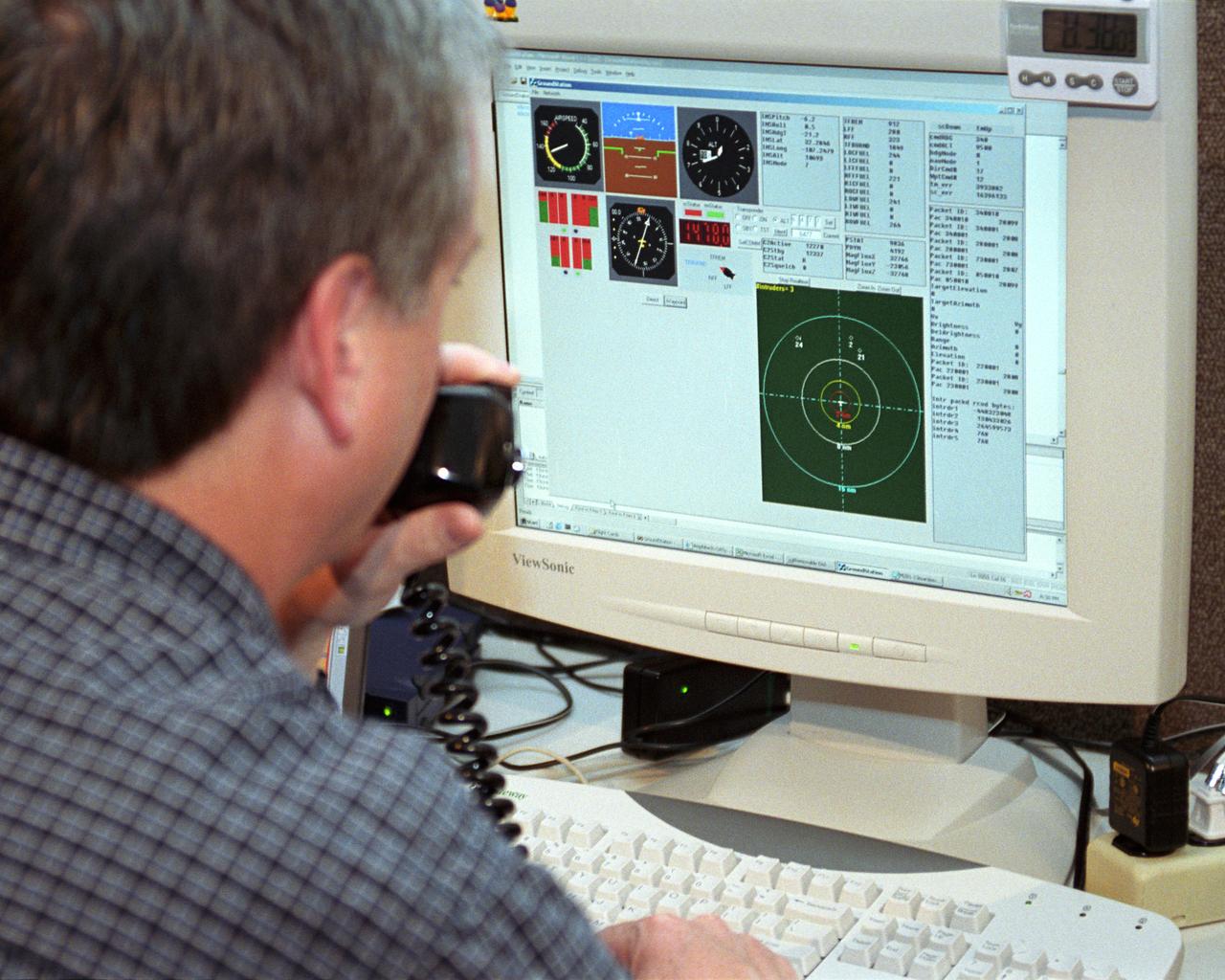
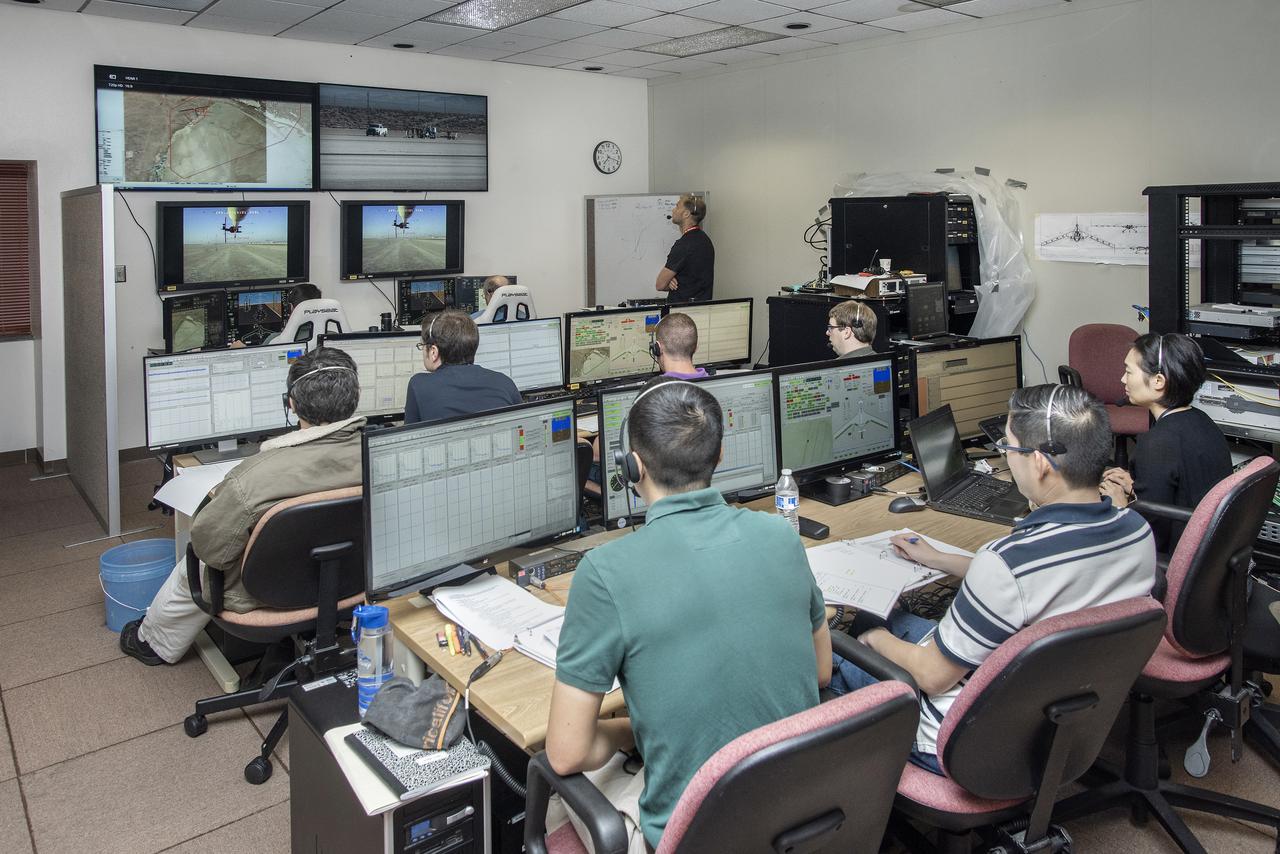
Engineers at NASA‘s Armstrong Flight Research Center sit in a control room to monitor the remotely-piloted Ikhana aircraft during a test flight. The test flight was used to validate key technologies and operations necessary to receive approval from the FAA’s to fly the aircraft in the National Airspace System June 12, 2018, without a safety chase aircraft.
Wing Deployment Sequence #3: The deployable, inflatable wing technology demonstrator experiment aircraft's wings fully deployed during flight following separation from its carrier aircraft during a flight conducted by the NASA Dryden Flight Research Center, Edwards, Californiaornia. The inflatable wing project represented a basic flight research effort by Dryden personnel. Three successful flights of the I2000 inflatable wing aircraft occurred. During the flights, the team air-launched the radio-controlled (R/C) I2000 from an R/C utility airplane at an altitude of 800-1000 feet. As the I2000 separated from the carrier aircraft, its inflatable wings "popped-out," deploying rapidly via an on-board nitrogen bottle. The aircraft remained stable as it transitioned from wingless to winged flight. The unpowered I2000 glided down to a smooth landing under complete control.
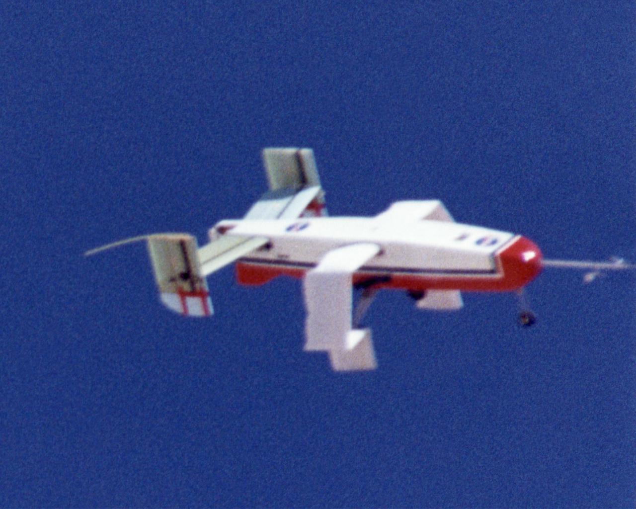
Wing Deployment Sequence #2: The deployable, inflatable wing technology demonstrator experiment aircraft's wings continue deploying following separation from its carrier aircraft during a flight conducted by the NASA Dryden Flight Research Center, Edwards, California. The inflatable wing project represented a basic flight research effort by Dryden personnel. Three successful flights of the I2000 inflatable wing aircraft occurred. During the flights, the team air-launched the radio-controlled (R/C) I2000 from an R/C utility airplane at an altitude of 800-1000 feet. As the I2000 separated from the carrier aircraft, its inflatable wings "popped-out," deploying rapidly via an on-board nitrogen bottle. The aircraft remained stable as it transitioned from wingless to winged flight. The unpowered I2000 glided down to a smooth landing under complete control.
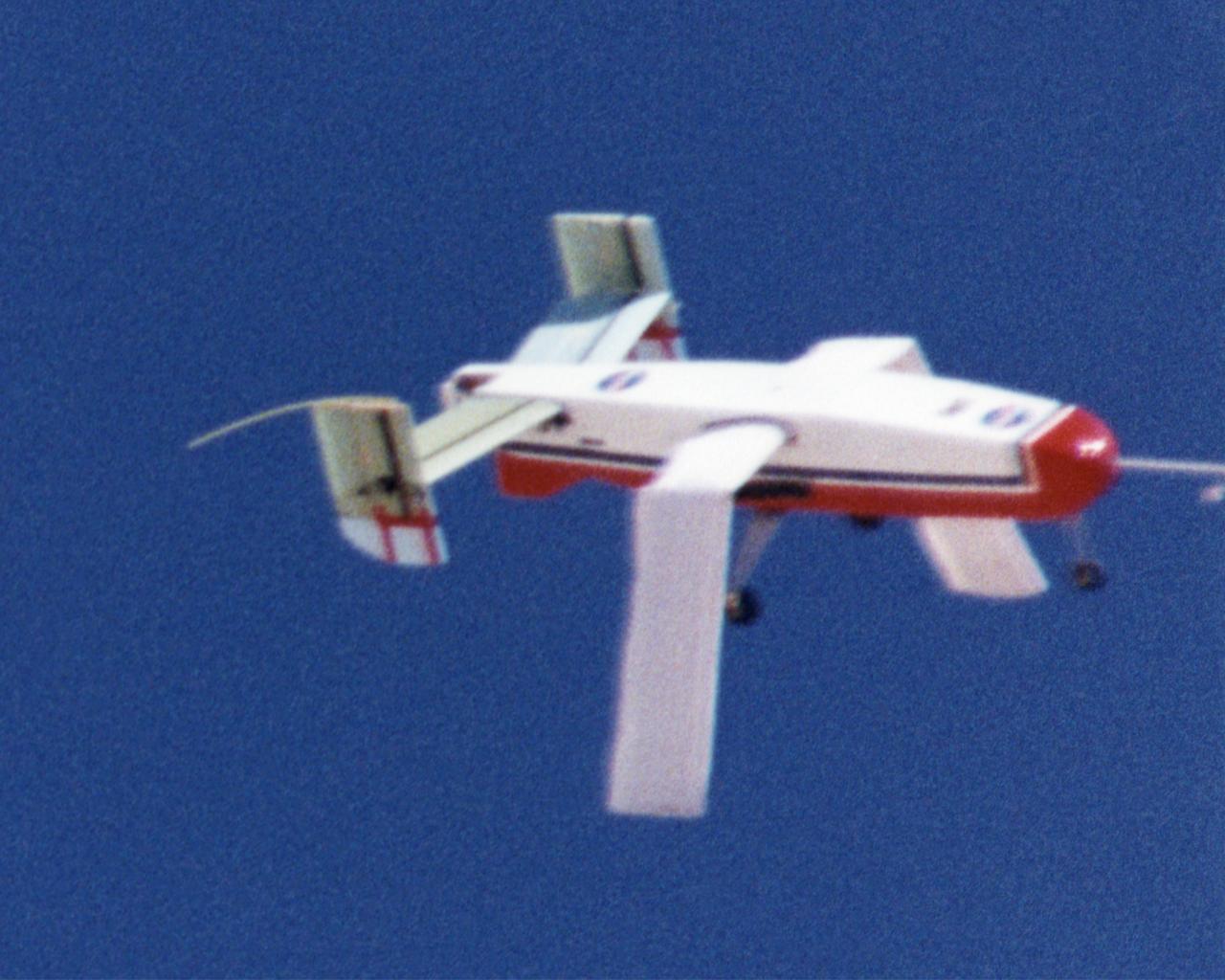
Wing Deployment Sequence #1: The deployable, inflatable wing technology demonstrator experiment aircraft's wings begin deploying following separation from its carrier aircraft during a flight conducted by the NASA Dryden Flight Research Center, Edwards, California. The inflatable wing project represented a basic flight research effort by Dryden personnel. Three successful flights of the I2000 inflatable wing aircraft occurred. During the flights, the team air-launched the radio-controlled (R/C) I2000 from an R/C utility airplane at an altitude of 800-1000 feet. As the I2000 separated from the carrier aircraft, its inflatable wings "popped-out," deploying rapidly via an on-board nitrogen bottle. The aircraft remained stable as it transitioned from wingless to winged flight. The unpowered I2000 glided down to a smooth landing under complete control.
The deployable, inflatable wing technology demonstrator experiment aircraft looks good during a flight conducted by the NASA Dryden Flight Research Center, Edwards, California. The inflatable wing project represented a basic flight research effort by Dryden personnel. Three successful flights of the I2000 inflatable wing aircraft occurred. During the flights, the team air-launched the radio-controlled (R/C) I2000 from an R/C utility airplane at an altitude of 800-1000 feet. As the I2000 separated from the carrier aircraft, its inflatable wings "popped-out," deploying rapidly via an on-board nitrogen bottle. The aircraft remained stable as it transitioned from wingless to winged flight. The unpowered I2000 glided down to a smooth landing under complete control.
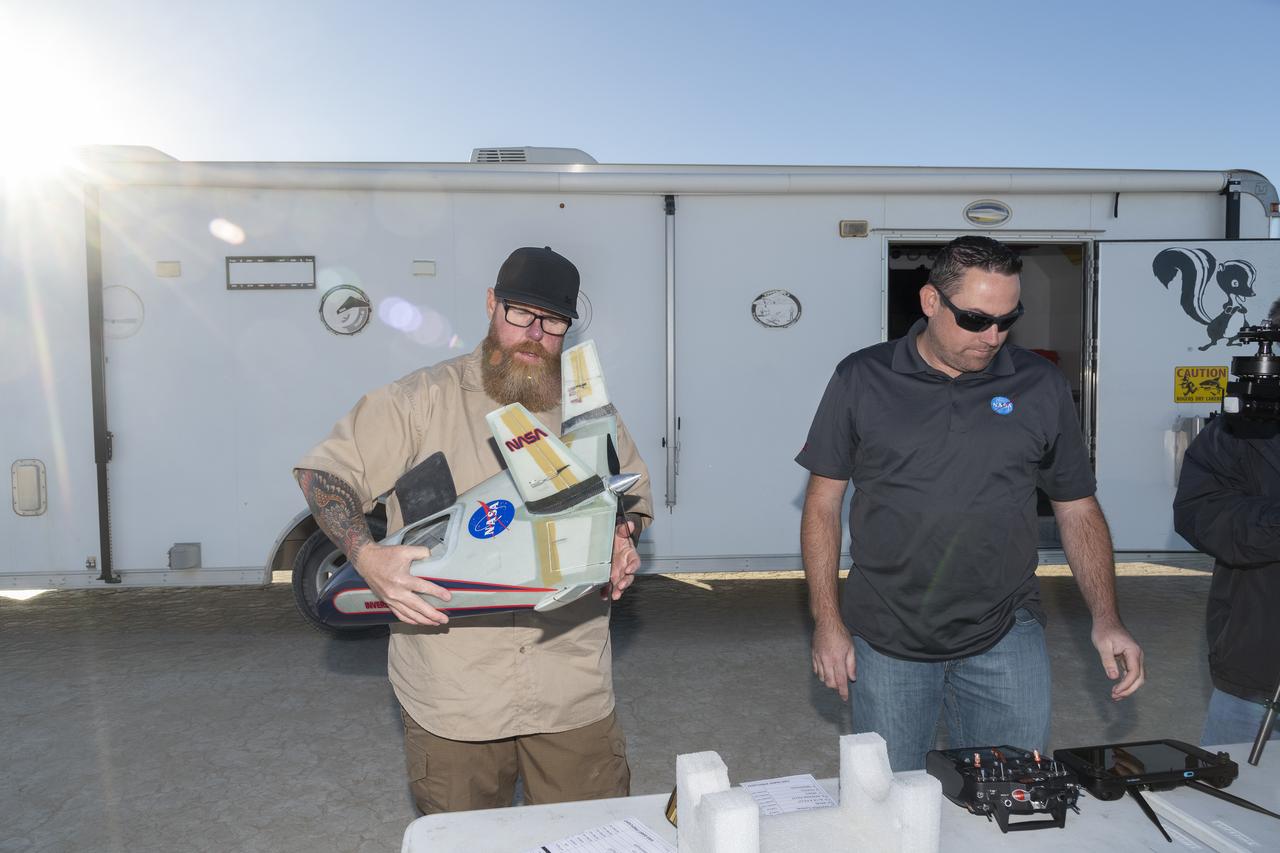
Justin Hall, left, chief pilot of small unmanned aircraft systems, carries the atmospheric probe at NASA’s Armstrong Flight Research Center in Edwards, California. The probe, which was designed and built at the center, flew after release from a quad rotor remotely piloted aircraft on Oct. 22, 2024, above Rogers Dry Lake, a flight area adjacent to the NASA center. At right, Justin Link, unmanned aircraft systems pilot, checks out the controllers for the two aircraft.
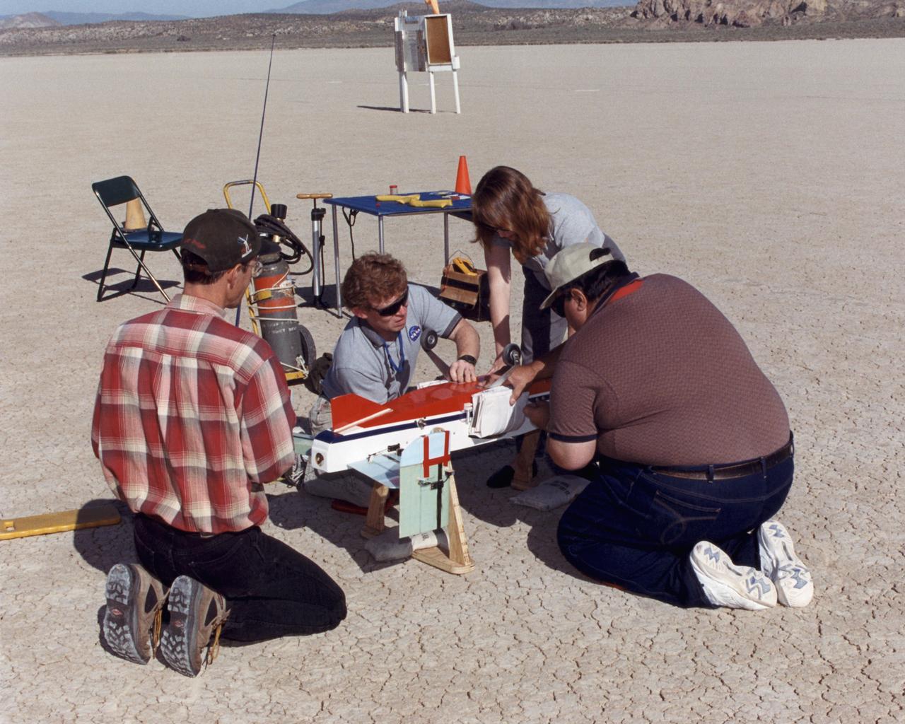
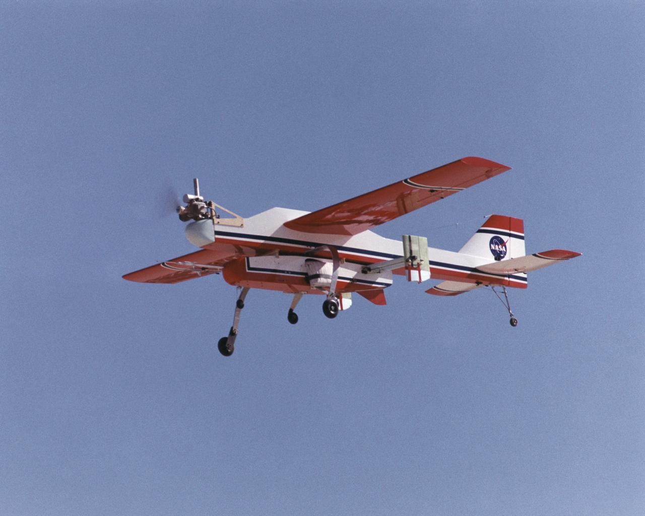
Inflatable Wing project personnel prepare a deployable, inflatable wing technology demonstrator experiment flown by the NASA Dryden Flight Research Center, Edwards, California. The inflatable wing project represented a basic flight research effort by Dryden personnel. Three successful flights of the I2000 inflatable wing aircraft occurred. During the flights, the team air-launched the radio-controlled (R/C) I2000 from an R/C utility airplane at an altitude of 800-1000 feet. As the I2000 separated from the carrier aircraft, its inflatable wings "popped-out," deploying rapidly via an on-board nitrogen bottle. The aircraft remained stable as it transitioned from wingless to winged flight. The unpowered I2000 glided down to a smooth landing under complete control.
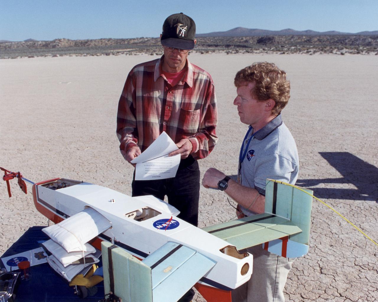
Engineers Jim Murray and Joe Pahle prepare a deployable, inflatable wing technology demonstrator experiment flown by the NASA Dryden Flight Research Center, Edwards, California. The inflatable wing project represented a basic flight research effort by Dryden personnel. Three successful flights of the I2000 inflatable wing aircraft occurred. During the flights, the team air-launched the radio-controlled (R/C) I2000 from an R/C utility airplane at an altitude of 800-1000 feet. As the I2000 separated from the carrier aircraft, its inflatable wings "popped-out," deploying rapidly via an on-board nitrogen bottle. The aircraft remained stable as it transitioned from wingless to winged flight. The unpowered I2000 glided down to a smooth landing under complete control.
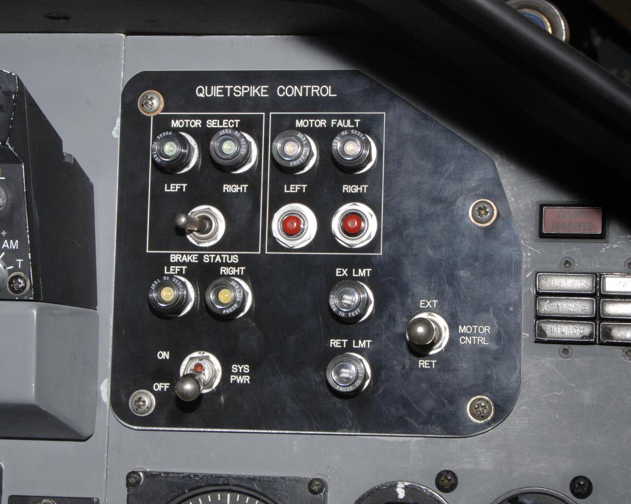
The control panel for the joint NASA/Gulfstream Quiet Spike project, located in the backseat of NASA's F-15B testbed aircraft. The project seeks to verify the structural integrity of the multi-segmented, articulating spike attachment designed to reduce and control a sonic boom.
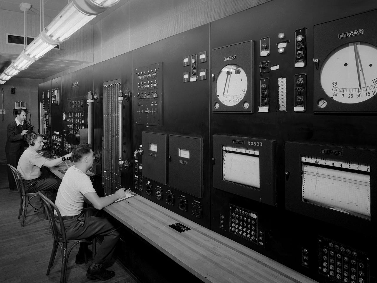
Operators in the control room for the Altitude Wind Tunnel at the National Advisory Committee for Aeronautics (NACA) Aircraft Engine Research Laboratory remotely operate a Wright R–3350 engine in the tunnel’s test section. Four of the engines were used to power the B–29 Superfortress, a critical weapon in the Pacific theater during World War II. The wind tunnel, which had been in operation for approximately six months, was the nation’s only wind tunnel capable of testing full-scale engines in simulated altitude conditions. The soundproof control room was used to operate the wind tunnel and control the engine being run in the test section. The operators worked with assistants in the adjacent Exhauster Building and Refrigeration Building to manage the large altitude simulation systems. The operator at the center console controlled the tunnel’s drive fan and operated the engine in the test section. Two sets of pneumatic levers near his right forearm controlled engine fuel flow, speed, and cooling. Panels on the opposite wall, out of view to the left, were used to manage the combustion air, refrigeration, and exhauster systems. The control panel also displayed the master air speed, altitude, and temperature gauges, as well as a plethora of pressure, temperature, and airflow readings from different locations on the engine. The operator to the right monitored the manometer tubes to determine the pressure levels. Despite just being a few feet away from the roaring engine, the control room remained quiet during the tests.
NASA's Ikhana unmanned science aircraft ground control station includes consoles for two pilots and positions for scientists and engineers along the side.
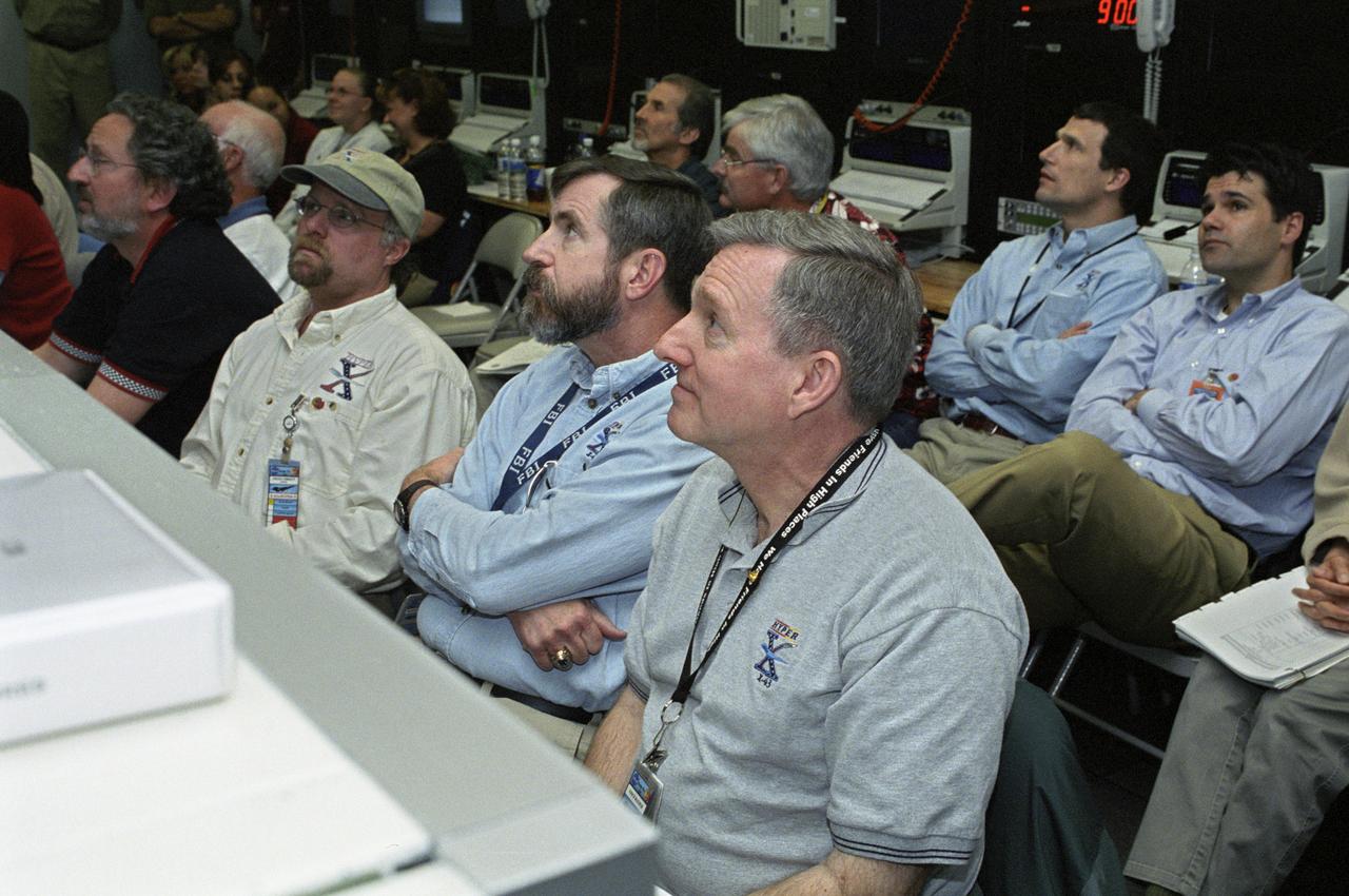
NASA personnel in a control room during the successful second flight of the X-43A aircraft. front row, left to right: Randy Voland, LaRC Propulsion; Craig Christy, Boeing Systems; Dave Reubush, NASA Hyper-X Deputy Program Manager; and Vince Rausch, NASA Hyper-X Program Manager. back row, left to right: Bill Talley, DCI/consultant; Pat Stoliker, DFRC Director (Acting) of Research Engineering; John Martin, LaRC G&C; and Dave Bose, AMA/Controls.
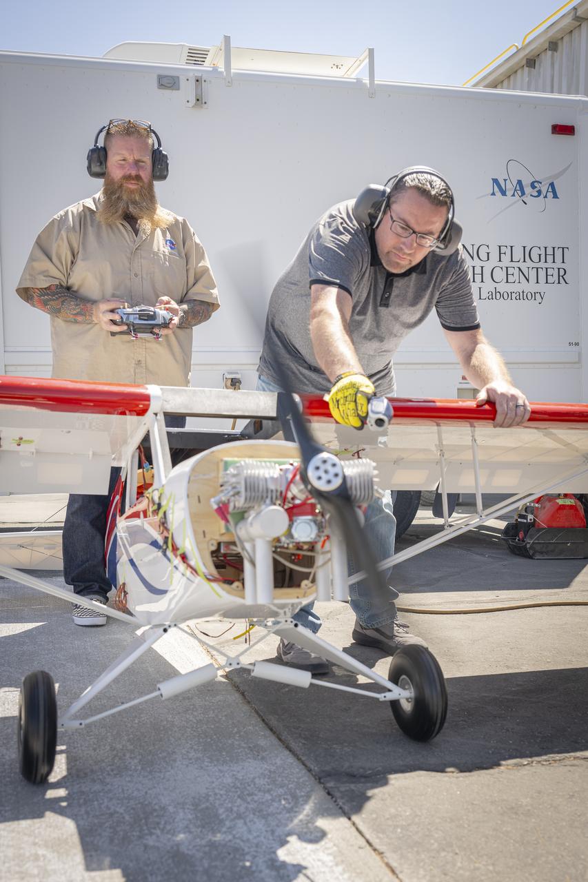
Justin Hall, left, controls a subscale aircraft as Justin Link holds the aircraft in place during preliminary engine tests on Friday, Sept. 12, 2025, at NASA’s Armstong Flight Research Center in Edwards, California. Hall is chief pilot at the center’s Dale Reed Subscale Flight Research Laboratory and Link is a pilot for small uncrewed aircraft systems.
Scaled Composites' Doug Shane examines the screen of his ground control station during tests in New Mexico. Shane used this configuration as the ground control station to remotely pilot the Proteus aircraft during a NASA sponsored series of tests.
Here is a close-up of the GE F414 engine, from the aft deck or rear, before the tail section of the X-59 is lifted into place and attached to the aircraft. The aft deck helps control the shockwaves at the end of the aircraft and reduce the noise of a sonic boom to more of a sonic thump.

Event: Horizontal Stabilator Install The Low Boom Flight Demonstrator manufacturing team installed the horizontal stabilizers to the aircraft. These are used along with the flight control computers to keep the airplane flying safely and providing the pitch control so that the pilot can fly the missions envisioned for the X-59

Event: Horizontal Stabilator Install The Low Boom Flight Demonstrator manufacturing team installed the horizontal stabilizers to the aircraft. These are used along with the flight control computers to keep the airplane flying safely and providing the pitch control so that the pilot can fly the missions envisioned for the X-59.

Event: Horizontal Stabilator Install The Low Boom Flight Demonstrator manufacturing team installed the horizontal stabilizers to the aircraft. These are used along with the flight control computers to keep the airplane flying safely and providing the pitch control so that the pilot can fly the missions envisioned for the X-59.

Event: Horizontal Stabilator Install The Low Boom Flight Demonstrator manufacturing team installed the horizontal stabilizers to the aircraft. These are used along with the flight control computers to keep the airplane flying safely and providing the pitch control so that the pilot can fly the missions envisioned for the X-59.
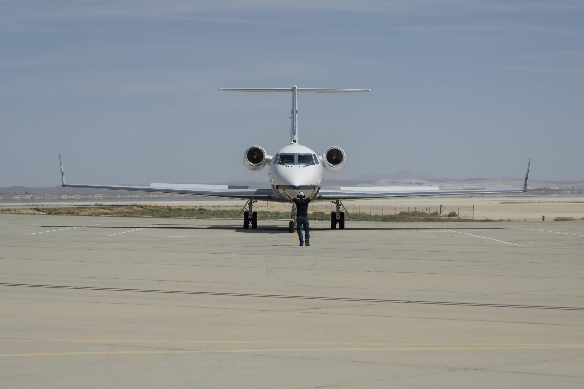
Manny Rodriguez, Gulfstream G-III crew chief, completes flight control checks with the pilots on Friday, March 27, 2026, at NASA’s Armstrong Flight Research Center in Edwards, California. The G-III will join other NASA aircraft to capture imagery of the Orion spacecraft’s heat shield during Artemis II reentry. The mission is part of NASA’s Scientifically Calibrated In-Flight Imagery (SCIFLI) project, based at NASA’s Langley Research Center in Hampton, Virginia.
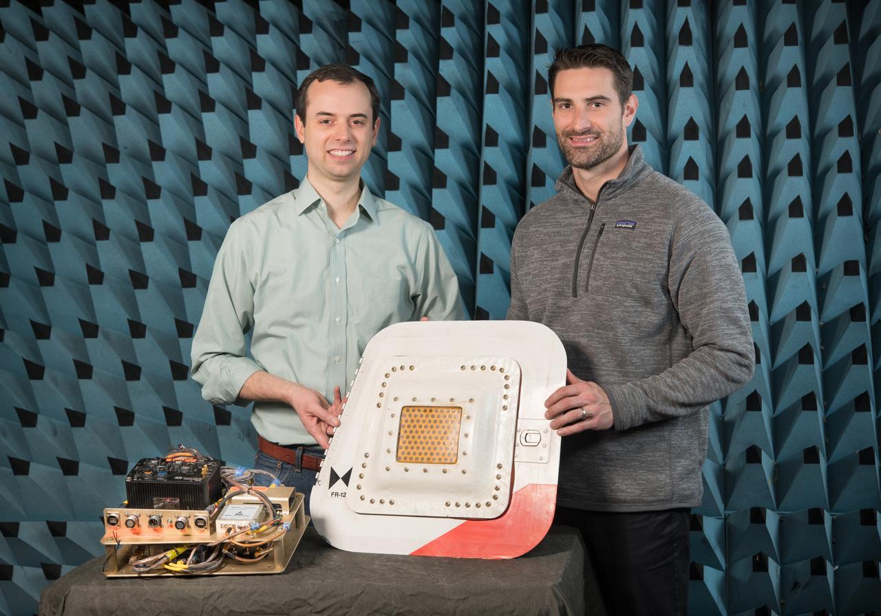
Flight Electronics Payload for Curved Confocal Lightweight Antenna Structures for Aeronautical Communications Technologies, CLAS-ACT, Phased Array Antenna on T-34-C Aircraft Door Flight Curved Confocal Lightweight Antenna Structures for Aeronautical Communications Technologies, CLAS-ACT, Phased Array Antenna Control / Flight Testing
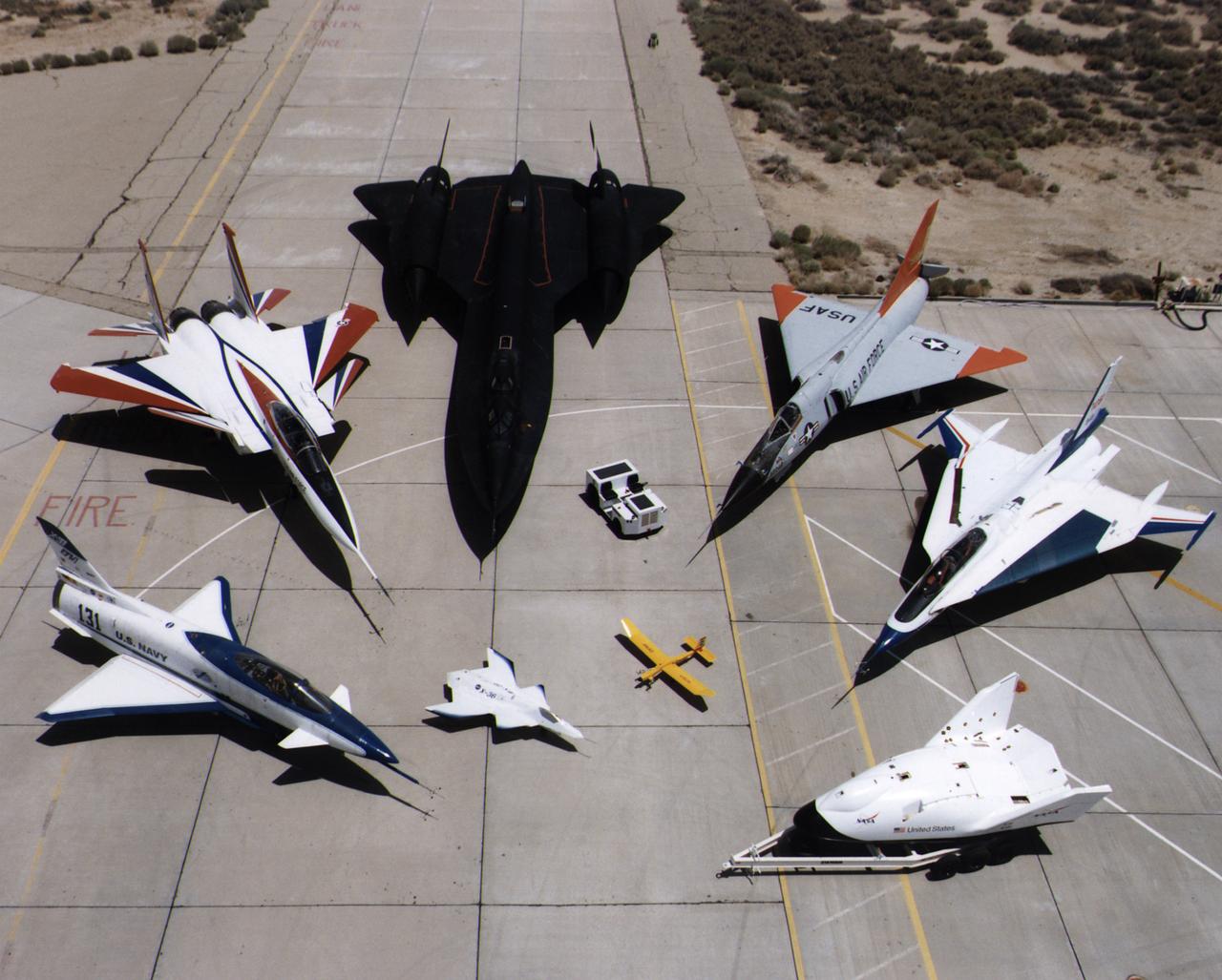
A collection of NASA's research aircraft on the ramp at the Dryden Flight Research Center in July 1997: X-31, F-15 ACTIVE, SR-71, F-106, F-16XL Ship #2, X-38, Radio Controlled Mothership and X-36.
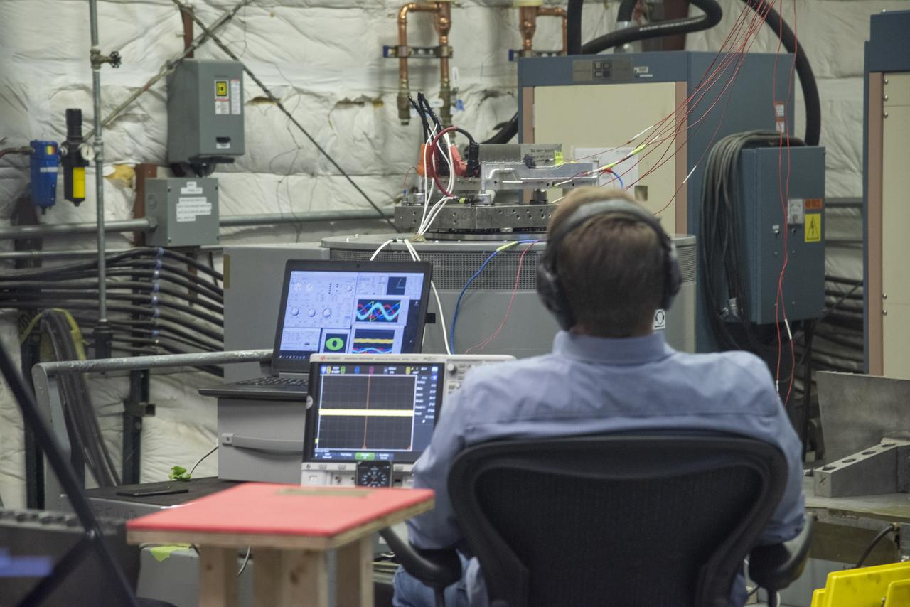
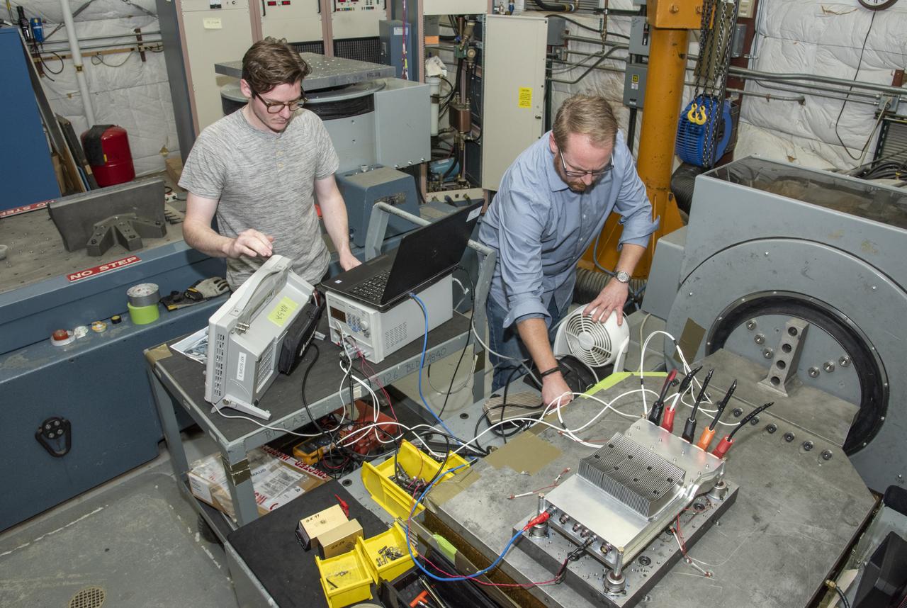
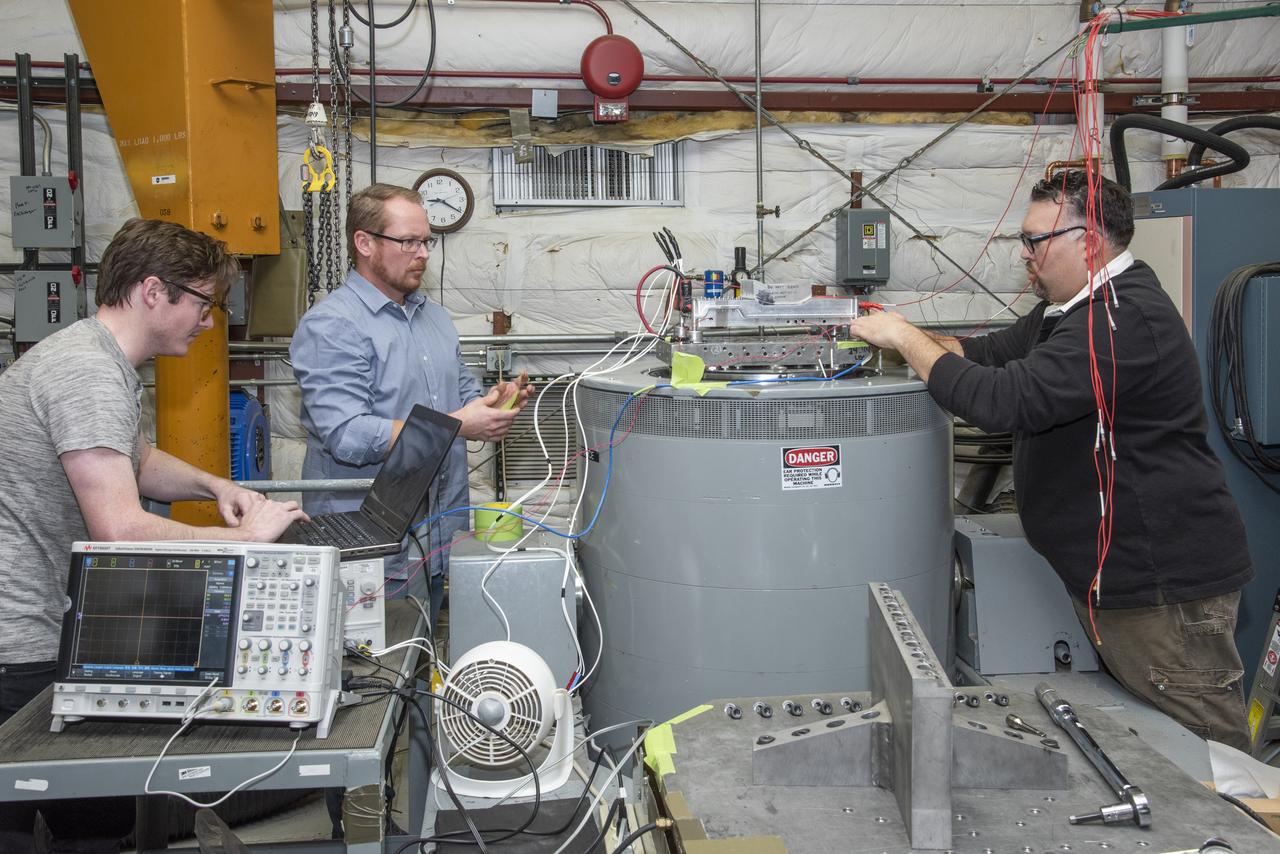
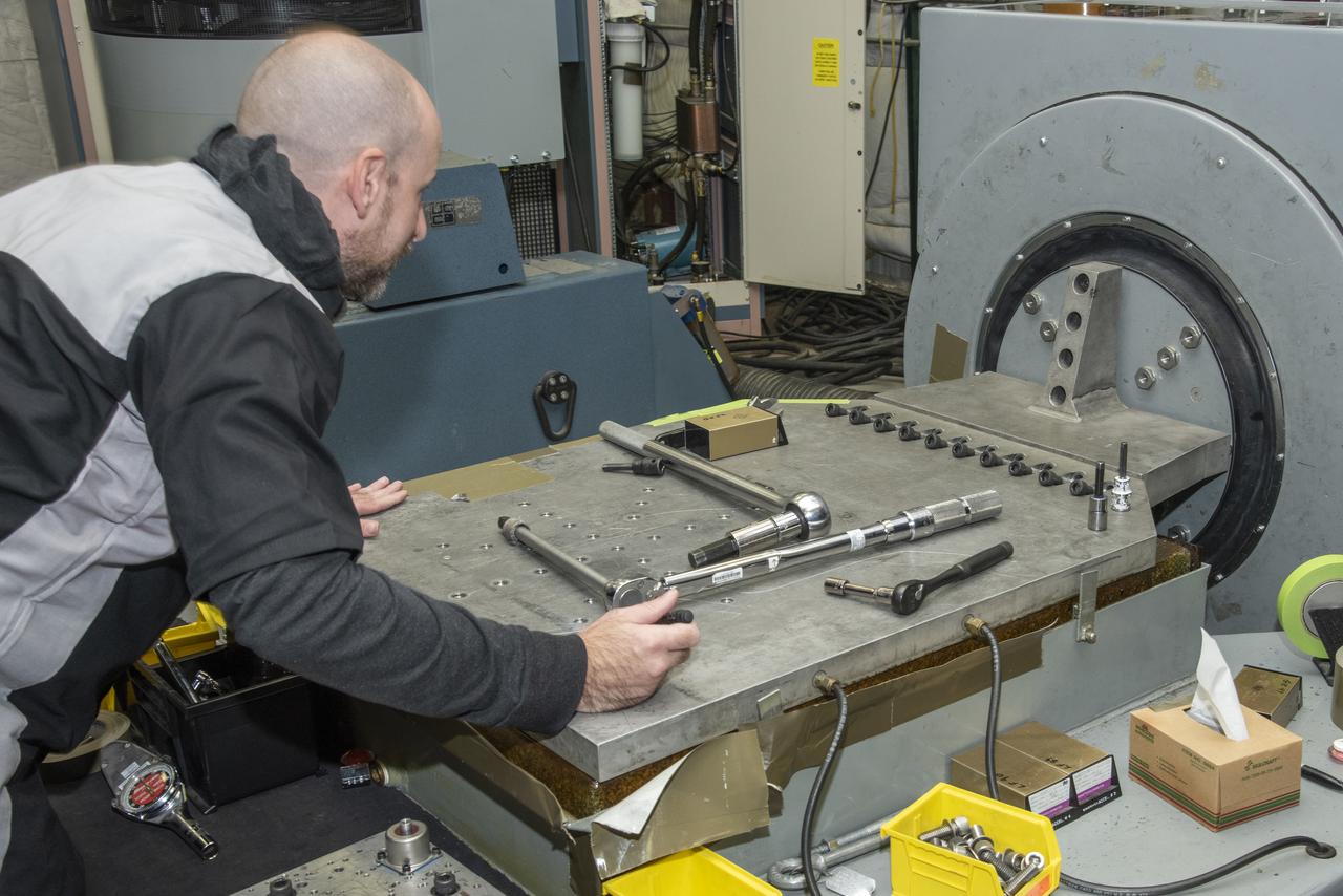
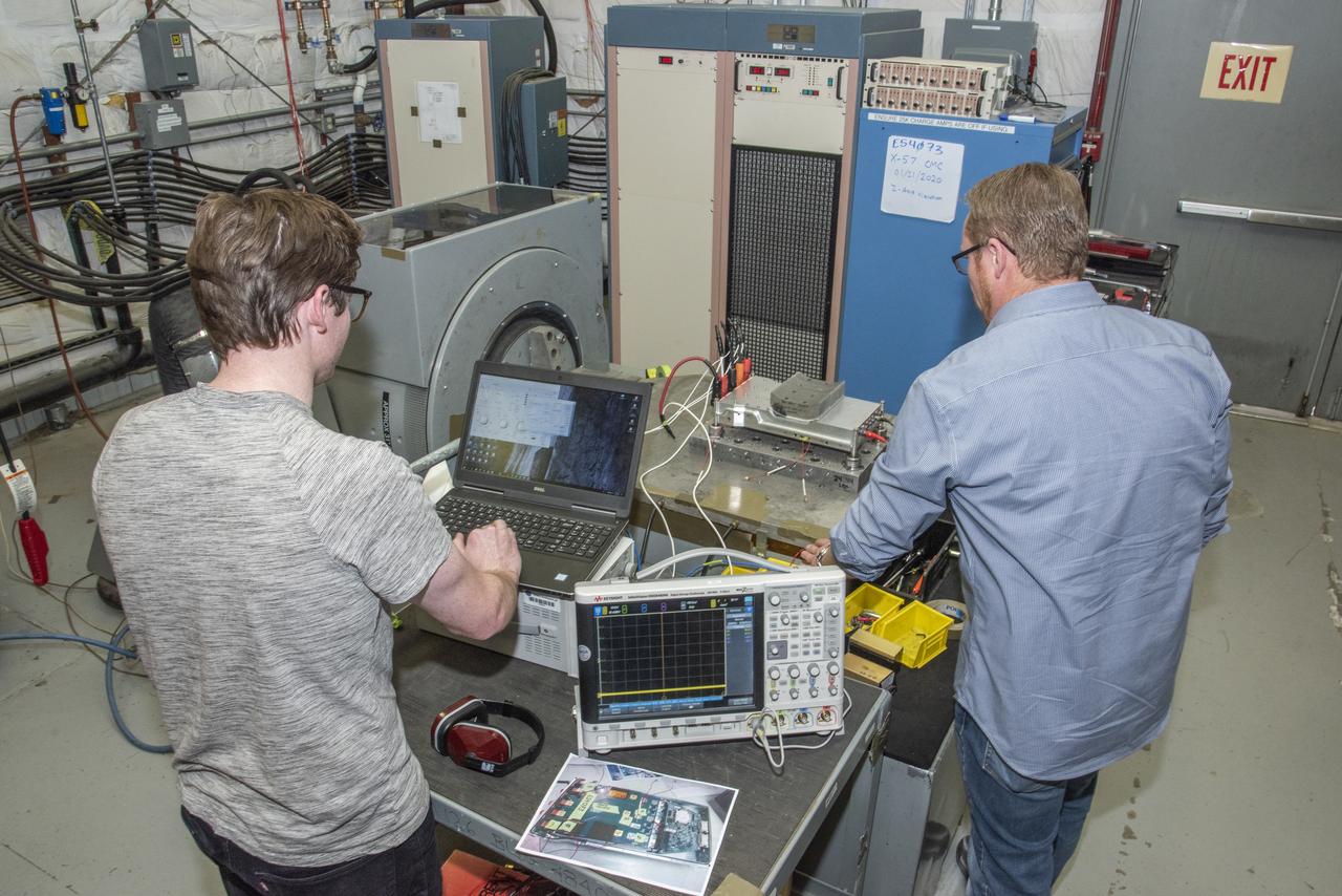
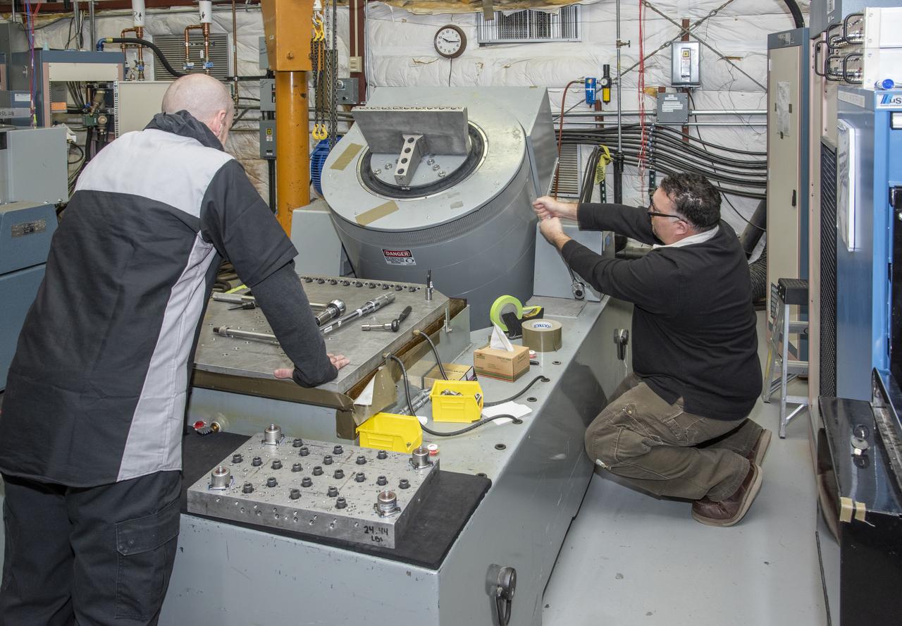
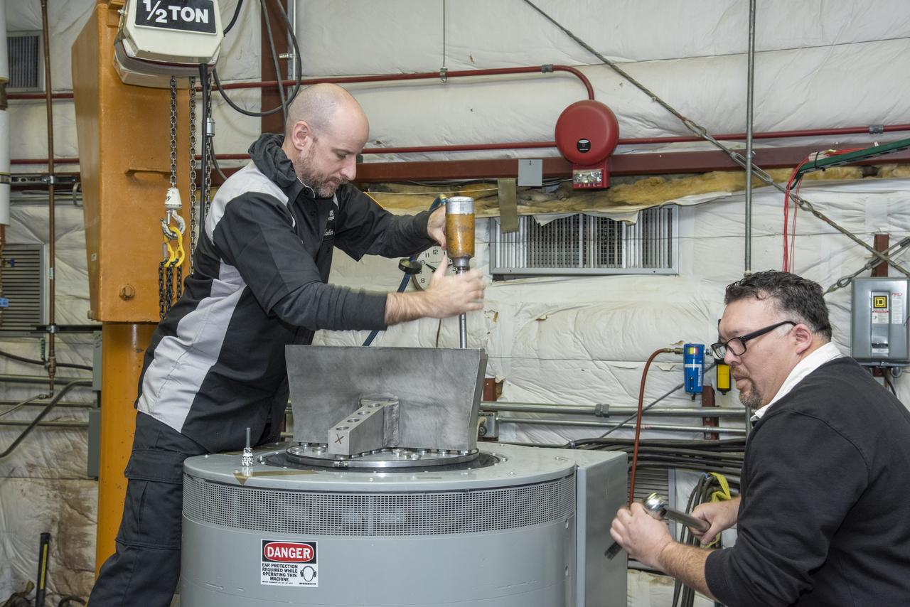
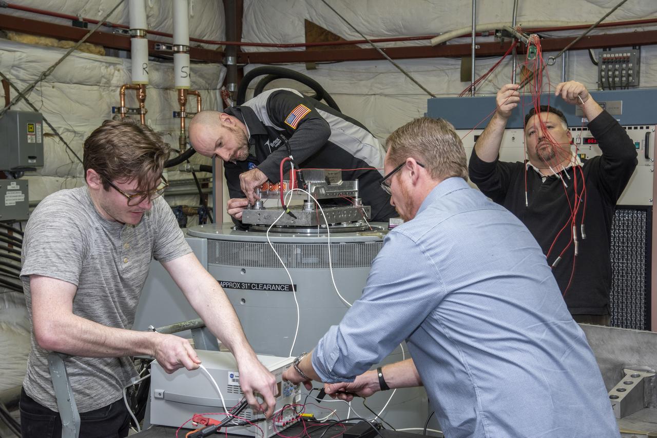
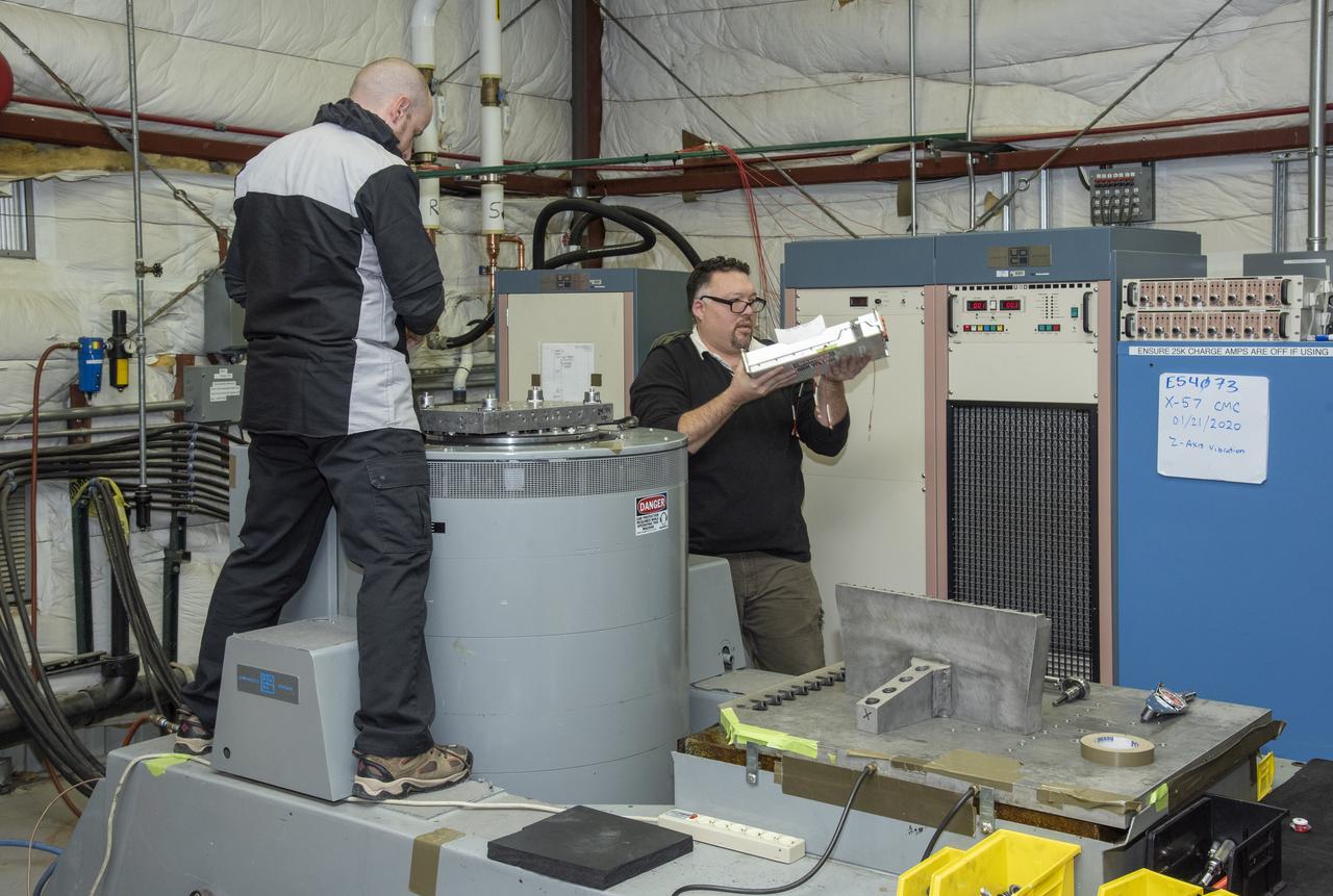
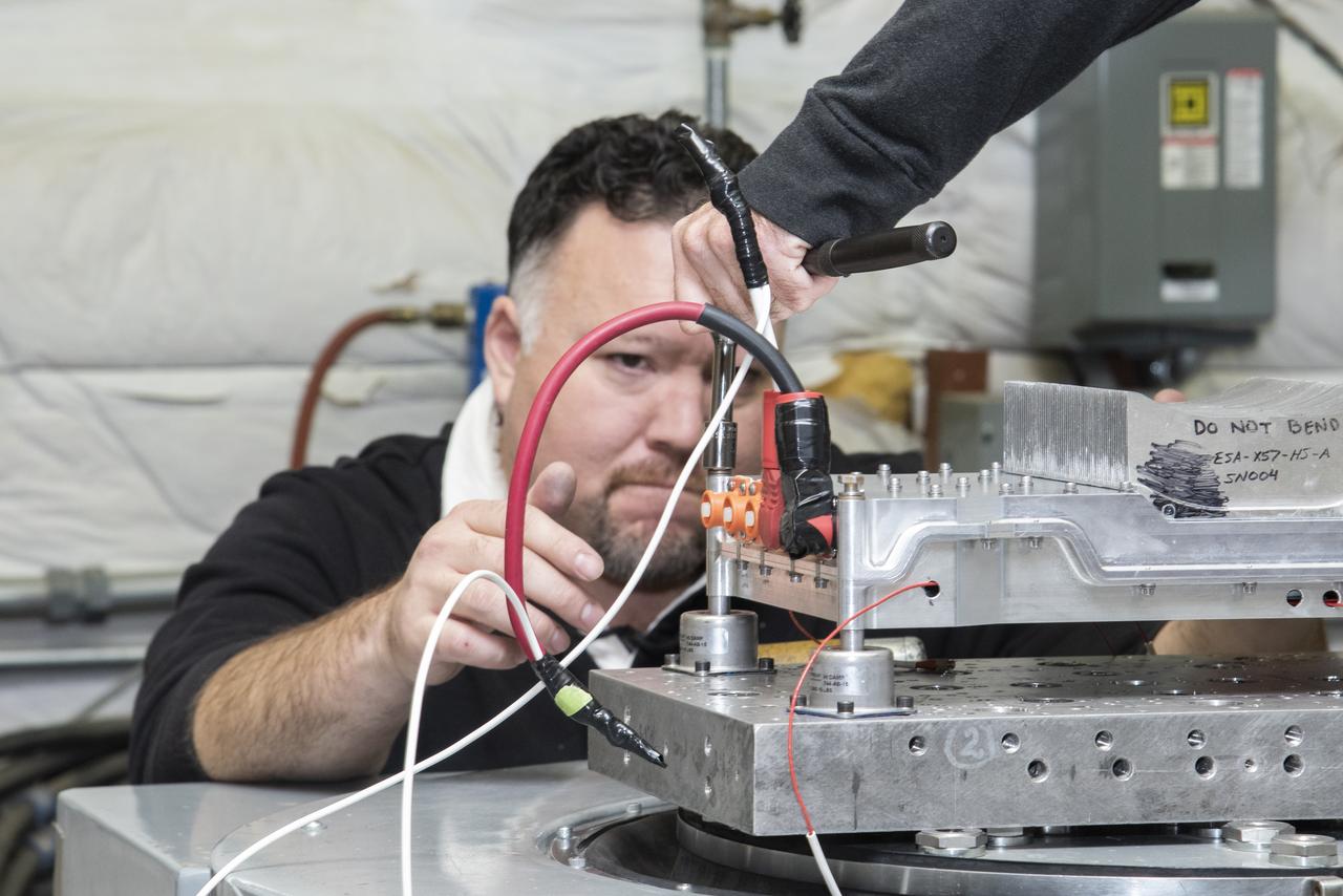
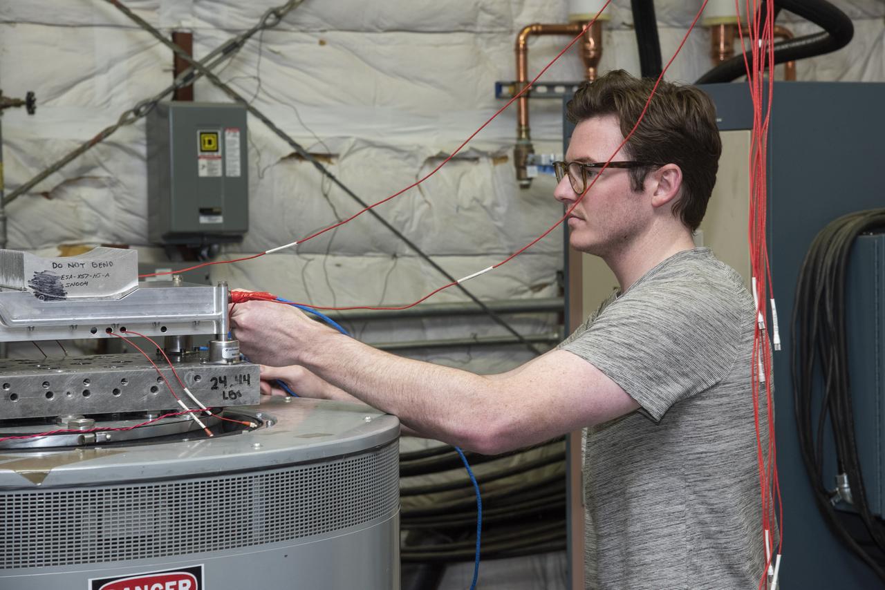
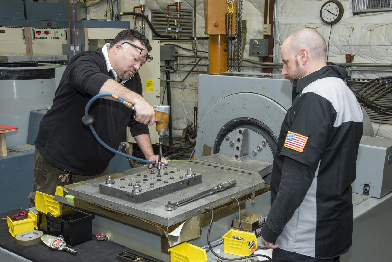
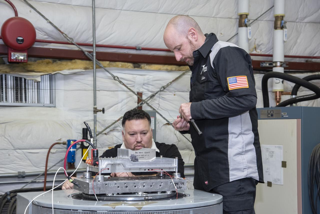
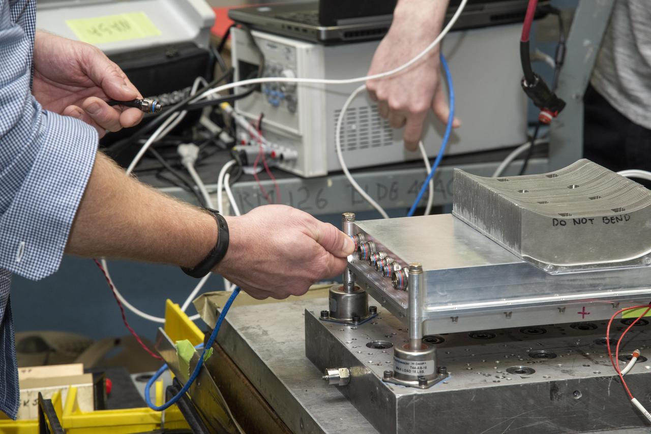
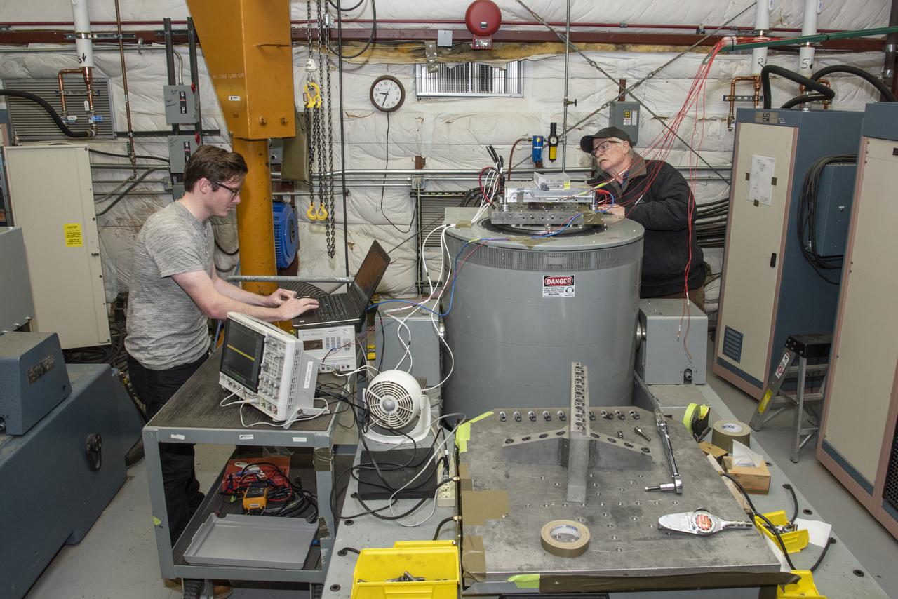
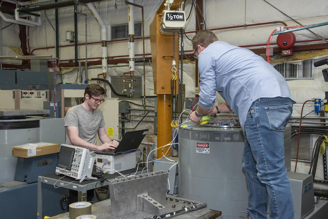
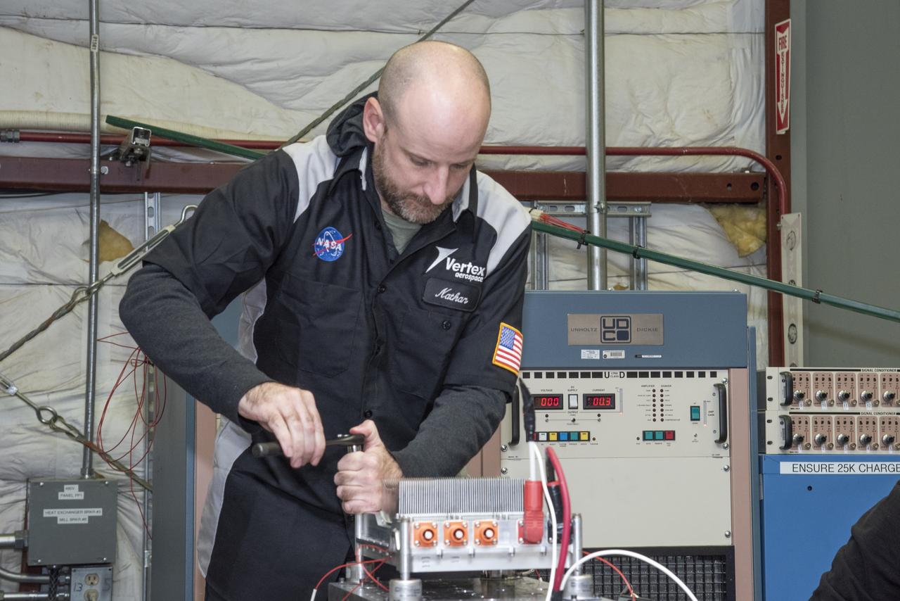
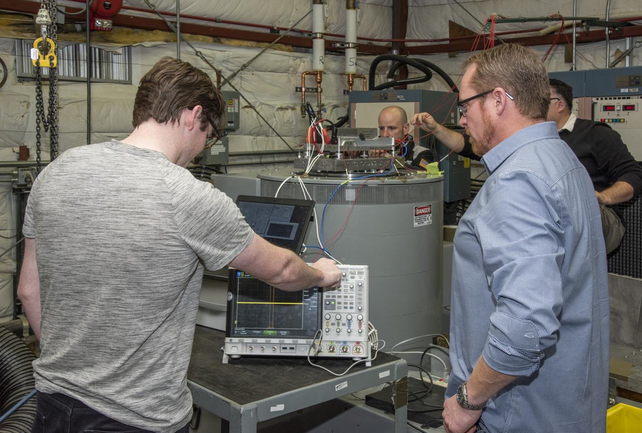
A cruise motor controller for the X-57 Maxwell, NASA's first all-electric X-plane, undergoes vibration testing at NASA Armstrong Flight Research Center's environmental lab. The cruise motor controller is exposed to two levels of vibration on three different axes, helping NASA to examine the integrity of the controller for flight conditions. The cruise motor controller will be a critical component for providing power to X-57's motors when the aircraft takes to the skies in 2020.
A cruise motor controller for the X-57 Maxwell, NASA's first all-electric X-plane, undergoes vibration testing at NASA Armstrong Flight Research Center's environmental lab. The cruise motor controller is exposed to two levels of vibration on three different axes, helping NASA to examine the integrity of the controller for flight conditions. The cruise motor controller will be a critical component for providing power to X-57's motors when the aircraft takes to the skies in 2020.
A cruise motor controller for the X-57 Maxwell, NASA’s first all-electric X-plane, undergoes vibration testing at NASA Armstrong Flight Research Center’s environmental lab. The cruise motor controller is exposed to two levels of vibration on three different axes, helping NASA to examine the integrity of the controller for flight conditions. The cruise motor controller will be a critical component for providing power to X-57’s motors when the aircraft takes to the skies in 2020.

Here is an image of the X-59’s 13-foot General Electric F414 engine as the team prepares for a fit check. Making sure components, like the aircraft’s hydraulic lines, which help control functions like brakes or landing gear, and wiring of the engine, fit properly is essential to the aircraft’s safety. Once complete, the X-59 aircraft will demonstrate the ability to fly supersonic while reducing the loud sonic boom to a quiet sonic thump and help enable commercial supersonic air travel over land.
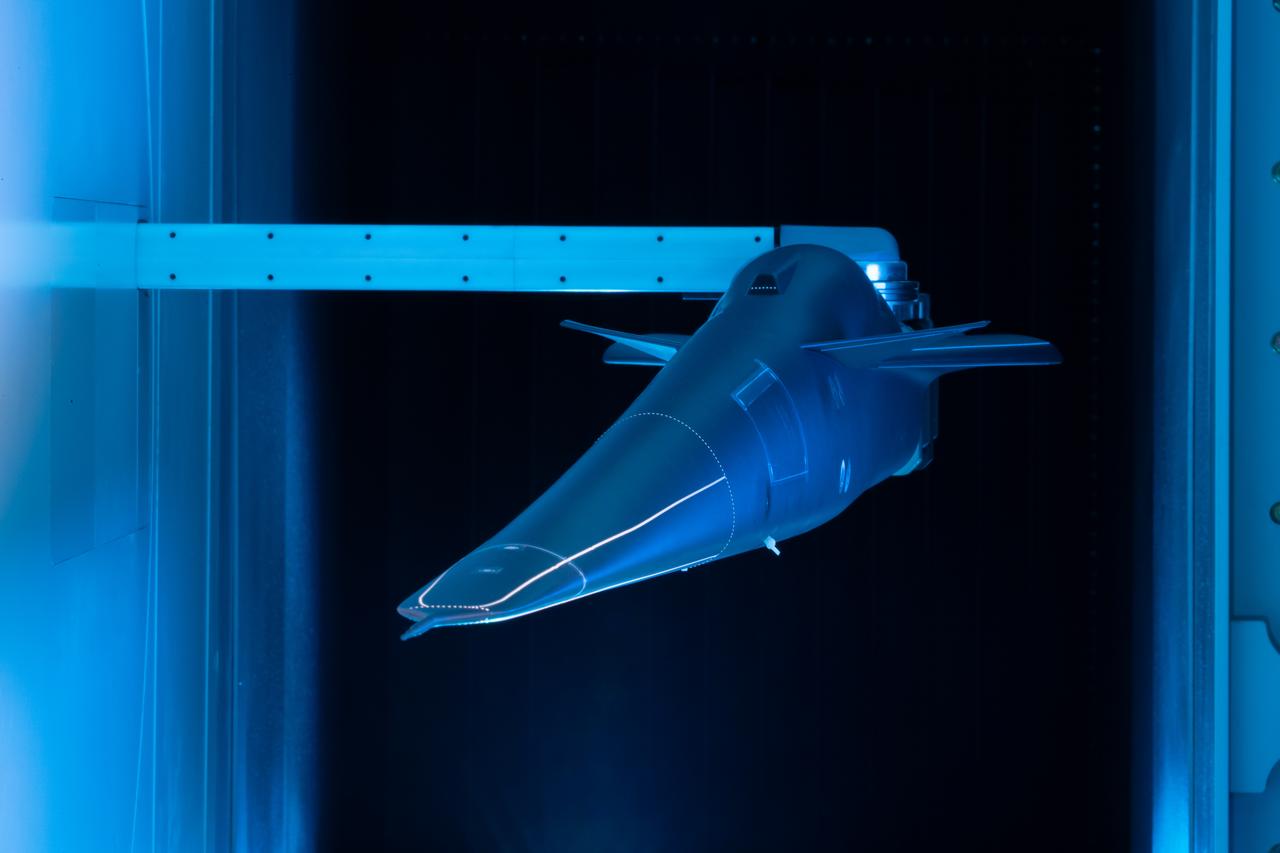
Event: Forebody and Nose - Windtunnel Testing A model of the X-59 forebody is shown in the Lockheed Martin Skunk Works’ wind tunnel in Palmdale, California. These tests gave the team measurements of wind flow angle around the aircraft’s nose and confirmed computer predictions made using computational fluid dynamics (CFD) software tools. The data will be fed into the aircraft flight control system to tell the pilot the aircraft’s altitude, speed and angle. This is part of NASA’s Quesst mission which plans to help enable supersonic air travel over land.
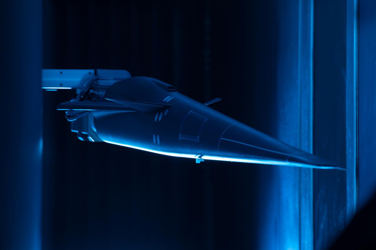
Event: Forebody and Nose - Windtunnel Testing A model of the X-59 forebody is shown in the Lockheed Martin Skunk Works’ wind tunnel in Palmdale, California. These tests gave the team measurements of wind flow angle around the aircraft’s nose and confirmed computer predictions made using computational fluid dynamics (CFD) software tools. The data will be fed into the aircraft flight control system to tell the pilot the aircraft’s altitude, speed and angle. This is part of NASA’s Quesst mission which plans to help enable supersonic air travel over land.
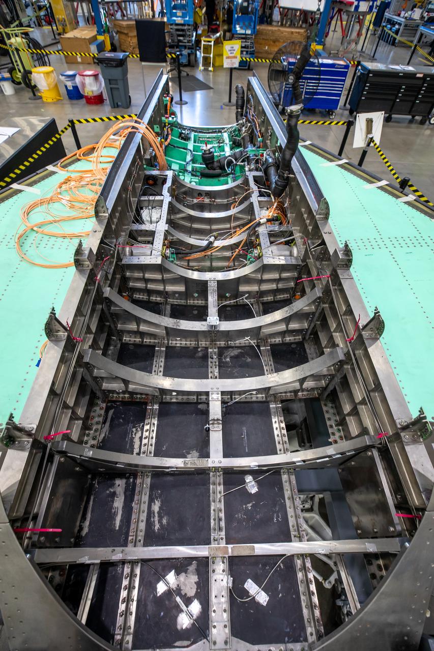
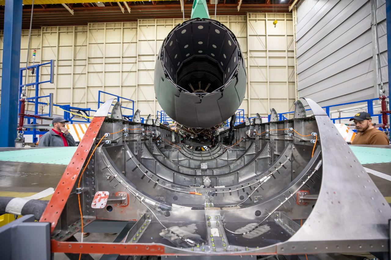
This image shows the X-59 aircraft’s lower empennage structure, or tail section of the plane, that was installed. The stabilators, the outer surfaces also seen in the photo, attach to the lower empennage and are used to help regulate the aircraft pitch which controls the up and down movement of the motion of the plane. The 13-foot engine will pack 22,000 pounds of propulsion and energy and power the X-plane to its planned cruising speed of Mach 1.4. Once complete, the X-59 aircraft will demonstrate the ability to fly supersonic while reducing the loud sonic boom to a quiet sonic thump and help enable commercial supersonic air travel over land. This aircraft is the centerpiece of NASA’s Quesst mission.

This view from a NASA Dryden F-18 chase aircraft shows Dryden's highly modified F-15B, tail number 837, which resumed Intelligent Flight Control System (IFCS) project flights on Dec. 6, 2002.
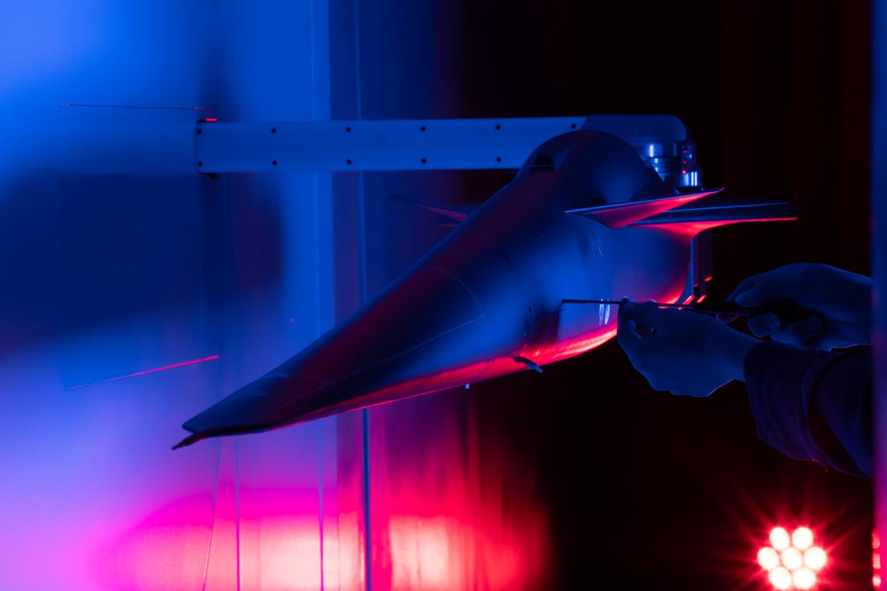
Event: Forebody and Nose - Windtunnel Testing A technician works on the X-59 model during testing in the low-speed wind tunnel at Lockheed Martin Skunk Works in Palmdale, California. These tests gave the team measurements of wind flow angle around the aircraft’s nose and confirmed computer predictions made using computational fluid dynamics (CFD) software tools. The data will be fed into the aircraft flight control system to tell the pilot the aircraft’s altitude, speed, and angle. This is part of NASA’s Quesst mission which plans to help enable supersonic air travel over land.
NASA engineer Larry Hudson and Ikhana ground crew member James Smith work on a ground validation test with new fiber optic sensors that led to validation flights on the Ikhana aircraft. NASA Dryden Flight Research Center is evaluating an advanced fiber optic-based sensing technology installed on the wings of NASA's Ikhana aircraft. The fiber optic system measures and displays the shape of the aircraft's wings in flight. There are other potential safety applications for the technology, such as vehicle structural health monitoring. If an aircraft structure can be monitored with sensors and a computer can manipulate flight control surfaces to compensate for stresses on the wings, structural control can be established to prevent situations that might otherwise result in a loss of control.

The F-8 Digital Fly-By-Wire aircraft had its hydro-mechanical control systems replaced by an Apollo Guidance Computer for the first such control system to fly.
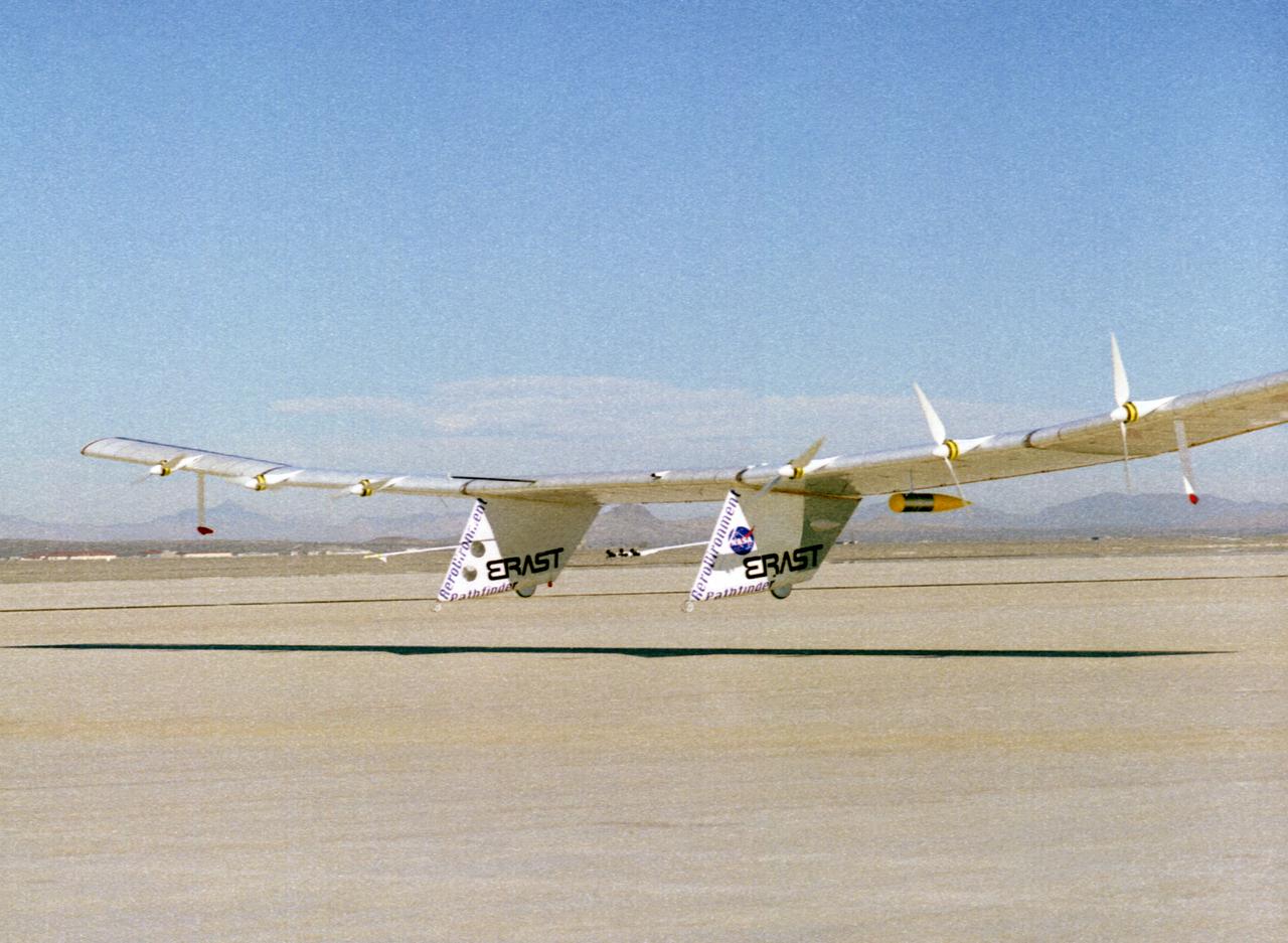
The Pathfinder solar-powered research aircraft settles in for landing on the bed of Rogers Dry Lake at the Dryden Flight Research Center, Edwards, California, after a successful test flight Nov. 19, 1996. The ultra-light craft flew a racetrack pattern at low altitudes over the flight test area for two hours while project engineers checked out various systems and sensors on the uninhabited aircraft. The Pathfinder was controlled by two pilots, one in a mobile control unit which followed the craft, the other in a stationary control station. Pathfinder, developed by AeroVironment, Inc., is one of several designs being evaluated under NASA's Environmental Research Aircraft and Sensor Technology (ERAST) program.
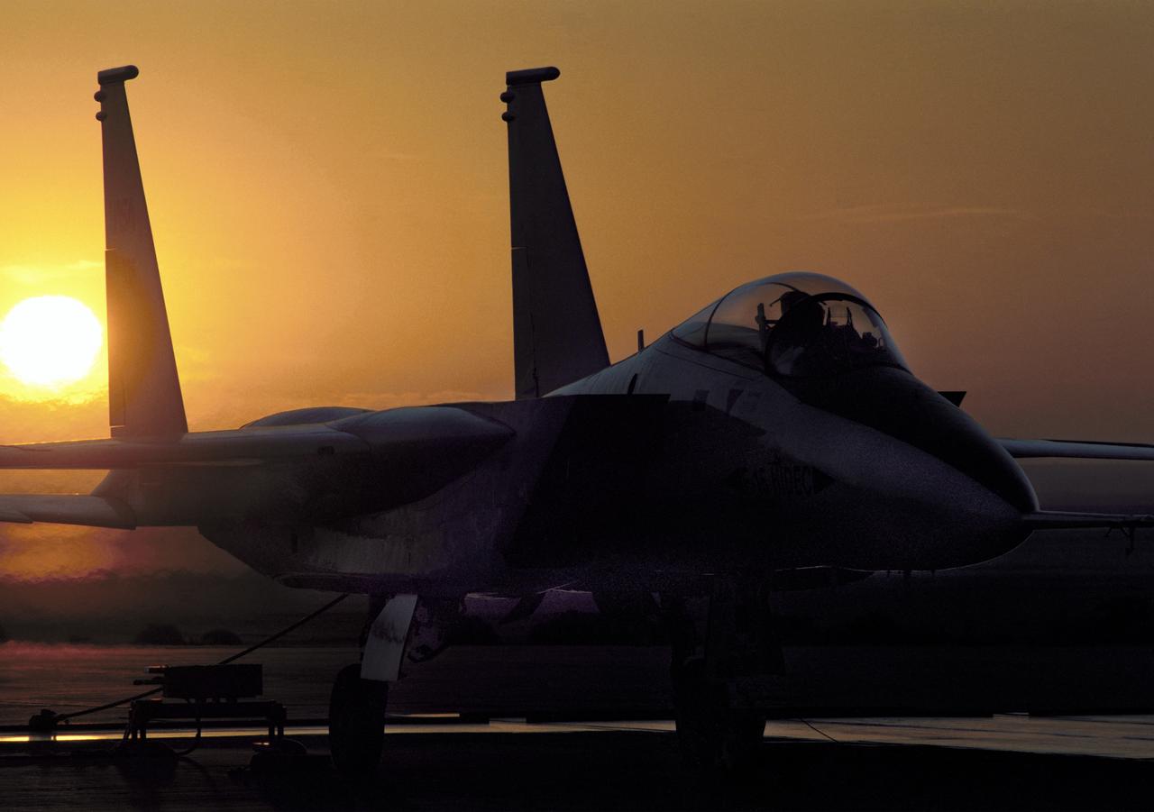
NASA's highly modified F-15A (Serial #71-0287) used for digital electronic flight and engine control systems research, at sunrise on the ramp at the Dryden Flight Research Facility, Edwards, California. The F-15 was called the HIDEC (Highly Integrated Digital Electronic Control) flight facility. Research programs flown on the testbed vehicle have demonstrated improved rates of climb, fuel savings, and engine thrust by optimizing systems performance. The aircraft also tested and evaluated a computerized self-repairing flight control system for the Air Force that detects damaged or failed flight control surfaces. The system then reconfigures undamaged control surfaces so the mission can continue or the aircraft is landed safely.
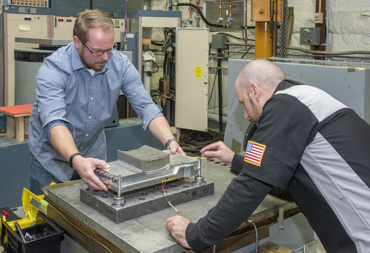
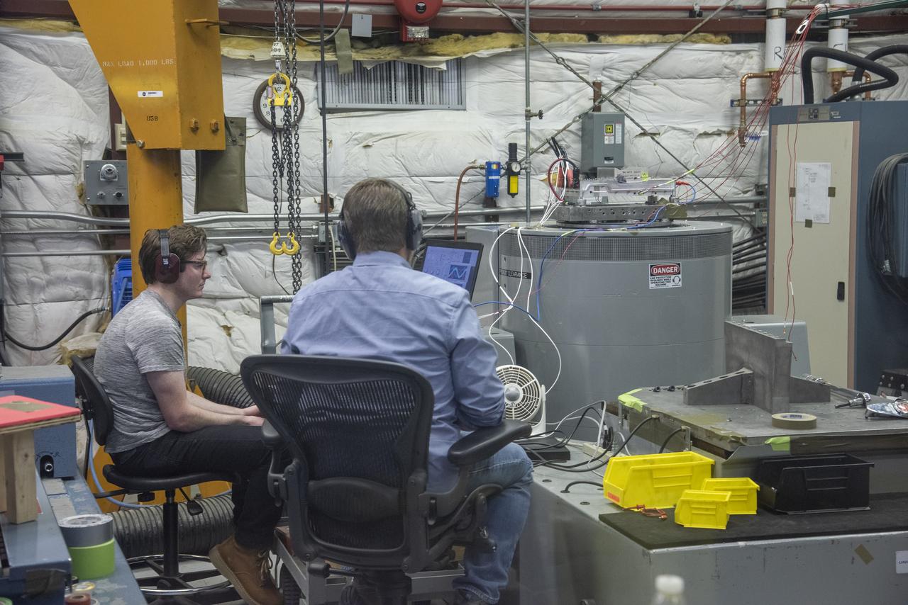
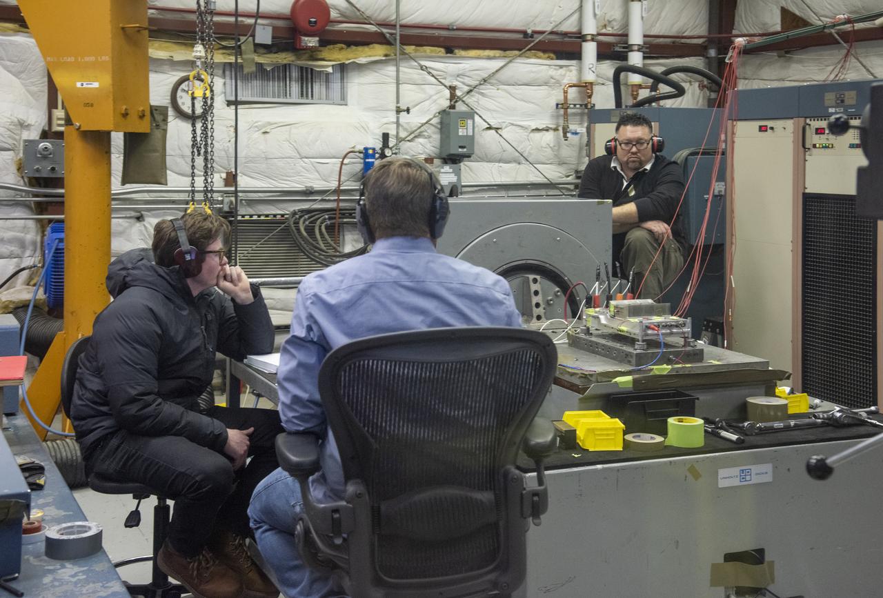
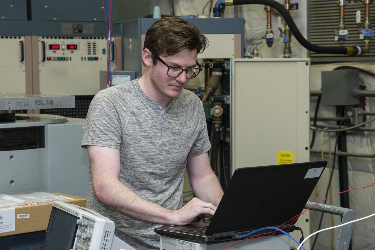
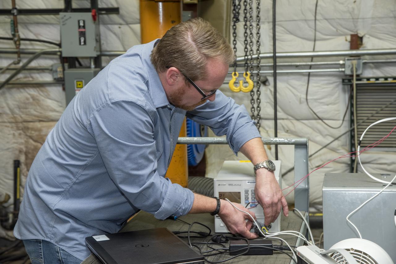
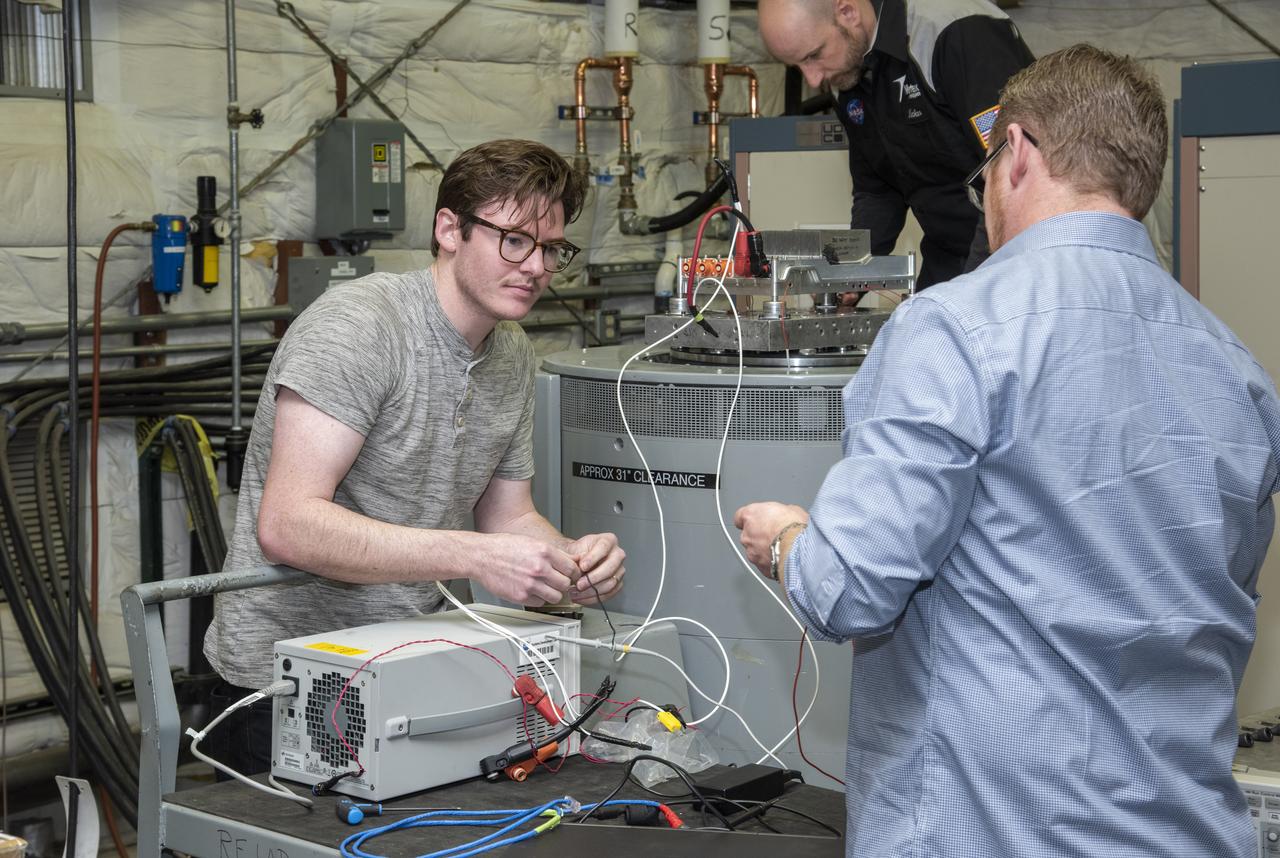
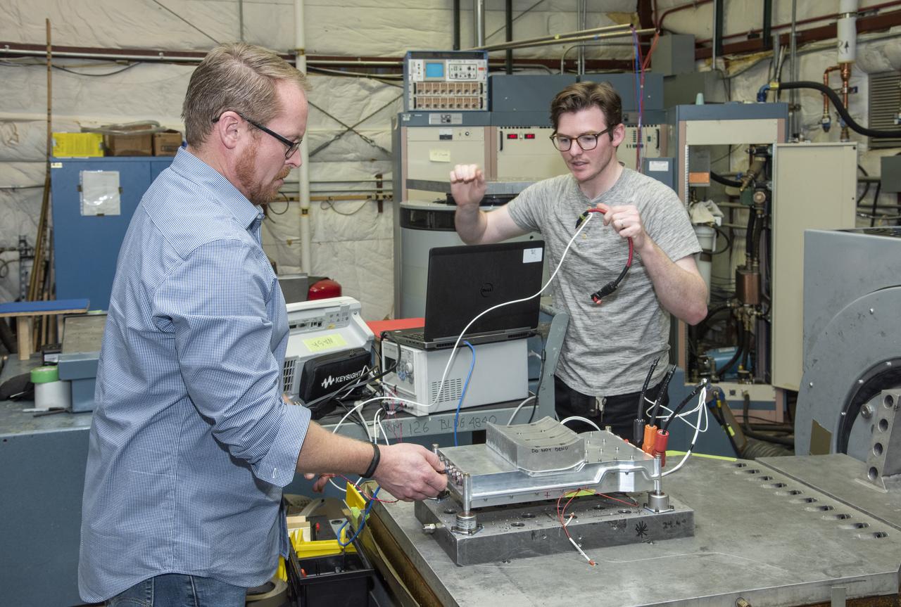
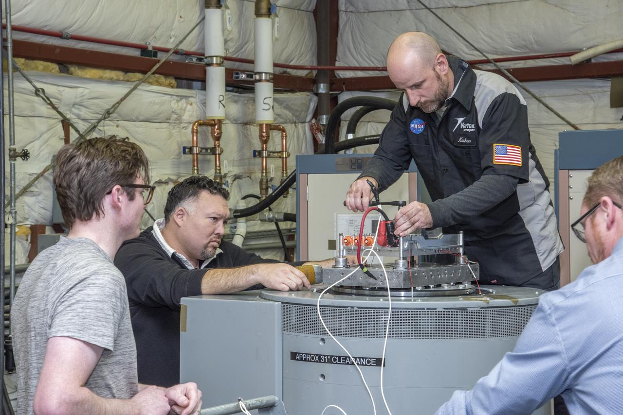
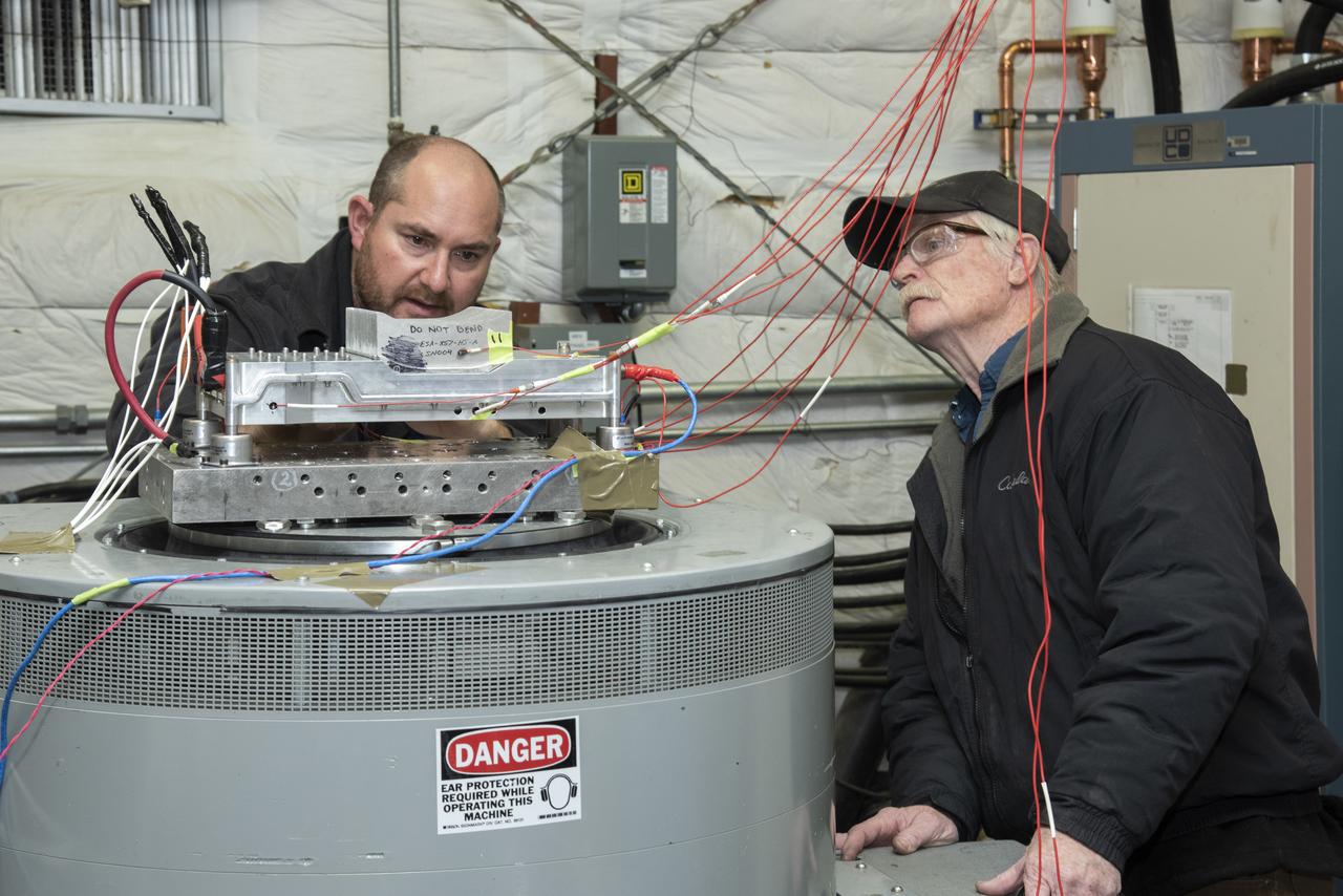
Engineers from NASA's Armstrong Flight Research Center and Empirical Systems Aerospace prepare a cruise motor controller, planned to be used on NASA's all-electric X-57 Maxwell, for vibration testing at Armstrong's environmental lab. Testing the cruise motor controller at various vibration levels, based on baseline flight testing in the project's first phase, helps ensure that the hardware will withstand similar vibration in flight conditions. X-57, NASA's first all-electric experimental aircraft, or X-plane, will fly in its first all-electric configuration in 2020.
Engineers from NASA’s Armstrong Flight Research Center and Empirical Systems Aerospace prepare a cruise motor controller, planned to be used on NASA’s all-electric X-57 Maxwell, for vibration testing at Armstrong’s environmental lab. Testing the cruise motor controller at various vibration levels, based on baseline flight testing in the project’s first phase, helps ensure that the hardware will withstand similar vibration in flight conditions. X-57, NASA’s first all-electric experimental aircraft, or X-plane, will fly in its first all-electric configuration in 2020.
Engineers from NASA's Armstrong Flight Research Center and Empirical Systems Aerospace prepare a cruise motor controller, planned to be used on NASA's all-electric X-57 Maxwell, for vibration testing at Armstrong's environmental lab. Testing the cruise motor controller at various vibration levels, based on baseline flight testing in the project's first phase, helps ensure that the hardware will withstand similar vibration in flight conditions. X-57, NASA's first all-electric experimental aircraft, or X-plane, will fly in its first all-electric configuration in 2020.
Engineers from NASA's Armstrong Flight Research Center and Empirical Systems Aerospace prepare a cruise motor controller, planned to be used on NASA's all-electric X-57 Maxwell, for vibration testing at Armstrong's environmental lab. Testing the cruise motor controller at various vibration levels, based on baseline flight testing in the project's first phase, helps ensure that the hardware will withstand similar vibration in flight conditions. X-57, NASA's first all-electric experimental aircraft, or X-plane, will fly in its first all-electric configuration in 2020.
Engineers from NASA's Armstrong Flight Research Center and Empirical Systems Aerospace prepare a cruise motor controller, planned to be used on NASA's all-electric X-57 Maxwell, for vibration testing at Armstrong's environmental lab. Testing the cruise motor controller at various vibration levels, based on baseline flight testing in the project's first phase, helps ensure that the hardware will withstand similar vibration in flight conditions. X-57, NASA's first all-electric experimental aircraft, or X-plane, will fly in its first all-electric configuration in 2020.
Engineers from NASA's Armstrong Flight Research Center and Empirical Systems Aerospace prepare a cruise motor controller, planned to be used on NASA's all-electric X-57 Maxwell, for vibration testing at Armstrong's environmental lab. Testing the cruise motor controller at various vibration levels, based on baseline flight testing in the project's first phase, helps ensure that the hardware will withstand similar vibration in flight conditions. X-57, NASA's first all-electric experimental aircraft, or X-plane, will fly in its first all-electric configuration in 2020.
Engineers from NASA's Armstrong Flight Research Center and Empirical Systems Aerospace prepare a cruise motor controller, planned to be used on NASA's all-electric X-57 Maxwell, for vibration testing at Armstrong's environmental lab. Testing the cruise motor controller at various vibration levels, based on baseline flight testing in the project's first phase, helps ensure that the hardware will withstand similar vibration in flight conditions. X-57, NASA's first all-electric experimental aircraft, or X-plane, will fly in its first all-electric configuration in 2020.
Engineers from NASA's Armstrong Flight Research Center and Empirical Systems Aerospace prepare a cruise motor controller, planned to be used on NASA's all-electric X-57 Maxwell, for vibration testing at Armstrong's environmental lab. Testing the cruise motor controller at various vibration levels, based on baseline flight testing in the project's first phase, helps ensure that the hardware will withstand similar vibration in flight conditions. X-57, NASA's first all-electric experimental aircraft, or X-plane, will fly in its first all-electric configuration in 2020.
Engineers from NASA's Armstrong Flight Research Center and Empirical Systems Aerospace prepare a cruise motor controller, planned to be used on NASA's all-electric X-57 Maxwell, for vibration testing at Armstrong's environmental lab. Testing the cruise motor controller at various vibration levels, based on baseline flight testing in the project's first phase, helps ensure that the hardware will withstand similar vibration in flight conditions. X-57, NASA's first all-electric experimental aircraft, or X-plane, will fly in its first all-electric configuration in 2020.
Engineers from NASA's Armstrong Flight Research Center and Empirical Systems Aerospace prepare a cruise motor controller, planned to be used on NASA's all-electric X-57 Maxwell, for vibration testing at Armstrong's environmental lab. Testing the cruise motor controller at various vibration levels, based on baseline flight testing in the project's first phase, helps ensure that the hardware will withstand similar vibration in flight conditions. X-57, NASA's first all-electric experimental aircraft, or X-plane, will fly in its first all-electric configuration in 2020.
Engineers from NASA’s Armstrong Flight Research Center and Empirical Systems Aerospace prepare a cruise motor controller, planned to be used on NASA’s all-electric X-57 Maxwell, for vibration testing at Armstrong’s environmental lab. Testing the cruise motor controller at various vibration levels, based on baseline flight testing in the project’s first phase, helps ensure that the hardware will withstand similar vibration in flight conditions. X-57, NASA’s first all-electric experimental aircraft, or X-plane, will fly in its first all-electric configuration in 2020.
Engineers from NASA’s Armstrong Flight Research Center and Empirical Systems Aerospace prepare a cruise motor controller, planned to be used on NASA’s all-electric X-57 Maxwell, for vibration testing at Armstrong’s environmental lab. Testing the cruise motor controller at various vibration levels, based on baseline flight testing in the project’s first phase, helps ensure that the hardware will withstand similar vibration in flight conditions. X-57, NASA’s first all-electric experimental aircraft, or X-plane, will fly in its first all-electric configuration in 2020.
Engineers from NASA's Armstrong Flight Research Center and Empirical Systems Aerospace prepare a cruise motor controller, planned to be used on NASA's all-electric X-57 Maxwell, for vibration testing at Armstrong's environmental lab. Testing the cruise motor controller at various vibration levels, based on baseline flight testing in the project's first phase, helps ensure that the hardware will withstand similar vibration in flight conditions. X-57, NASA's first all-electric experimental aircraft, or X-plane, will fly in its first all-electric configuration in 2020.
Engineers from NASA's Armstrong Flight Research Center and Empirical Systems Aerospace prepare a cruise motor controller, planned to be used on NASA's all-electric X-57 Maxwell, for vibration testing at Armstrong's environmental lab. Testing the cruise motor controller at various vibration levels, based on baseline flight testing in the project's first phase, helps ensure that the hardware will withstand similar vibration in flight conditions. X-57, NASA's first all-electric experimental aircraft, or X-plane, will fly in its first all-electric configuration in 2020.
Engineers from NASA's Armstrong Flight Research Center and Empirical Systems Aerospace prepare a cruise motor controller, planned to be used on NASA's all-electric X-57 Maxwell, for vibration testing at Armstrong's environmental lab. Testing the cruise motor controller at various vibration levels, based on baseline flight testing in the project's first phase, helps ensure that the hardware will withstand similar vibration in flight conditions. X-57, NASA's first all-electric experimental aircraft, or X-plane, will fly in its first all-electric configuration in 2020.
Engineers from NASA's Armstrong Flight Research Center and Empirical Systems Aerospace prepare a cruise motor controller, planned to be used on NASA's all-electric X-57 Maxwell, for vibration testing at Armstrong's environmental lab. Testing the cruise motor controller at various vibration levels, based on baseline flight testing in the project's first phase, helps ensure that the hardware will withstand similar vibration in flight conditions. X-57, NASA's first all-electric experimental aircraft, or X-plane, will fly in its first all-electric configuration in 2020.
Engineers from NASA's Armstrong Flight Research Center and Empirical Systems Aerospace prepare a cruise motor controller, planned to be used on NASA's all-electric X-57 Maxwell, for vibration testing at Armstrong's environmental lab. Testing the cruise motor controller at various vibration levels, based on baseline flight testing in the project's first phase, helps ensure that the hardware will withstand similar vibration in flight conditions. X-57, NASA's first all-electric experimental aircraft, or X-plane, will fly in its first all-electric configuration in 2020.
Engineers from NASA's Armstrong Flight Research Center and Empirical Systems Aerospace prepare a cruise motor controller, planned to be used on NASA's all-electric X-57 Maxwell, for vibration testing at Armstrong's environmental lab. Testing the cruise motor controller at various vibration levels, based on baseline flight testing in the project's first phase, helps ensure that the hardware will withstand similar vibration in flight conditions. X-57, NASAs first all-electric experimental aircraft, or X-plane, will fly in its first all-electric configuration in 2020.
Engineers from NASA's Armstrong Flight Research Center and Empirical Systems Aerospace prepare a cruise motor controller, planned to be used on NASA's all-electric X-57 Maxwell, for vibration testing at Armstrong's environmental lab. Testing the cruise motor controller at various vibration levels, based on baseline flight testing in the project's first phase, helps ensure that the hardware will withstand similar vibration in flight conditions. X-57, NASA's first all-electric experimental aircraft, or X-plane, will fly in its first all-electric configuration in 2020.
Engineers from NASA's Armstrong Flight Research Center and Empirical Systems Aerospace prepare a cruise motor controller, planned to be used on NASA's all-electric X-57 Maxwell, for vibration testing at Armstrong's environmental lab. Testing the cruise motor controller at various vibration levels, based on baseline flight testing in the project's first phase, helps ensure that the hardware will withstand similar vibration in flight conditions. X-57, NASA's first all-electric experimental aircraft, or X-plane, will fly in its first all-electric configuration in 2020.
Engineers from NASA's Armstrong Flight Research Center and Empirical Systems Aerospace prepare a cruise motor controller, planned to be used on NASA's all-electric X-57 Maxwell, for vibration testing at Armstrong's environmental lab. Testing the cruise motor controller at various vibration levels, based on baseline flight testing in the project's first phase, helps ensure that the hardware will withstand similar vibration in flight conditions. X-57, NASA's first all-electric experimental aircraft, or X-plane, will fly in its first all-electric configuration in 2020.
Engineers from NASA's Armstrong Flight Research Center and Empirical Systems Aerospace prepare a cruise motor controller, planned to be used on NASA's all-electric X-57 Maxwell, for vibration testing at Armstrong's environmental lab. Testing the cruise motor controller at various vibration levels, based on baseline flight testing in the project's first phase, helps ensure that the hardware will withstand similar vibration in flight conditions. X-57, NASA's first all-electric experimental aircraft, or X-plane, will fly in its first all-electric configuration in 2020.
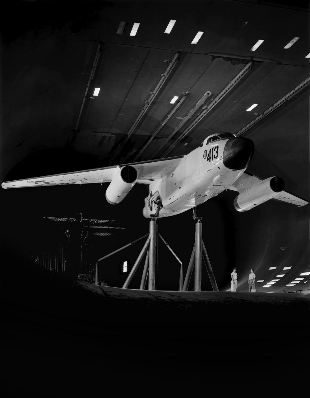
Testing the wing boundary layer control of the A3D in the 40 x 80 wind tunnel. Boundary layer control was added to increase the lift of the wing for aircraft carrier take off and landing.
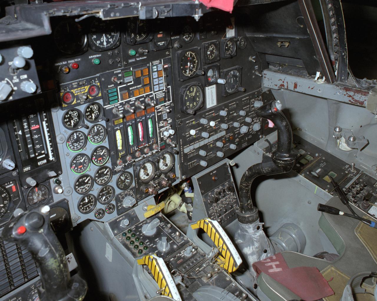
View of the right cockpit of the F-111 MAW aircraft. Unlike most fighter aircraft of the time, the F-111 had side-by-side seating. The pilot sat on the left side, and the weapons systems officer on the right. Both had control sticks to fly the aircraft.
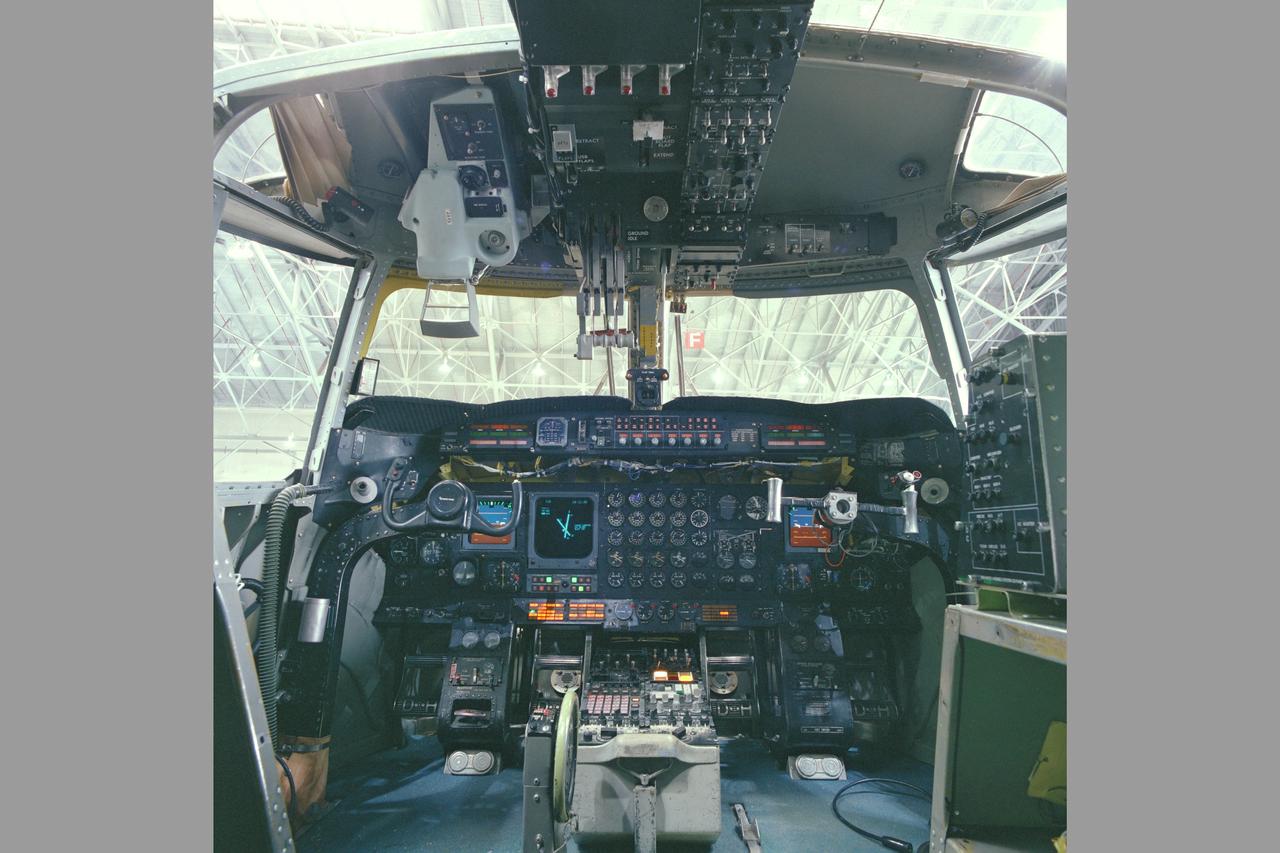
QSRA (QUIET STOL RESEARCH AIRCRAFT) COCKPIT SHOWING GUIDANCE EQUIPMENT, CONTROL AND DISPLAY
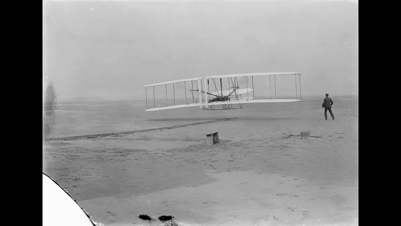
Orville Wright makes the first powered, controlled flight on Earth as his brother Wilbur looks on in this image taken at Kitty Hawk, North Carolina, on Dec. 17, 1903. Orville Wright covered 120 feet in 12 seconds during the first flight. The Wright brothers made four flights that day, each longer than the last. A small amount of the material that covered the wing of the aircraft, Flyer 1, during the first flight was flown to Mars aboard NASA's Ingenuity Mars Helicopter. An insulative tape was used to wrap the small swatch of fabric around a cable located underneath the helicopter's solar panel. Ingenuity is scheduled to attempt the first powered, controlled flight on another planet in April 2021. The Wrights had been using the same type of material – an unbleached muslin called "Pride of the West" – to cover their glider and aircraft wings since 1901. A different piece of the material, along with a small splinter of wood, from the Flyer 1 was flown to the Moon and back aboard Apollo 11. The image was taken by John Daniels, a member of the U.S. Life-Saving Station in Kill Devil Hills, North Carolina. Until the day of the flight, Daniels had never seen a camera. https://photojournal.jpl.nasa.gov/catalog/PIA24434
The control room for the remotely piloted X-56A has a feature that most do not – the pilot and co-pilot are in the front of the room, seen at left. The X-56A team has successfully suppressed flutter, which is a potentially destructive oscillation, with a classical and a modern controller. The controllers are essentially mathematical ways of directing the aircraft.
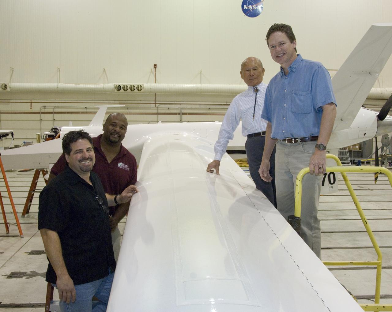
Ikhana fiber optic wing shape sensor team: clockwise from left, Anthony "Nino" Piazza, Allen Parker, William Ko and Lance Richards. The sensors, located along a fiber the thickness of a human hair, aren't visible in the center of the Ikhana aircraft's left wing. NASA Dryden Flight Research Center is evaluating an advanced fiber optic-based sensing technology installed on the wings of NASA's Ikhana aircraft. The fiber optic system measures and displays the shape of the aircraft's wings in flight. There are other potential safety applications for the technology, such as vehicle structural health monitoring. If an aircraft structure can be monitored with sensors and a computer can manipulate flight control surfaces to compensate for stresses on the wings, structural control can be established to prevent situations that might otherwise result in a loss of control.
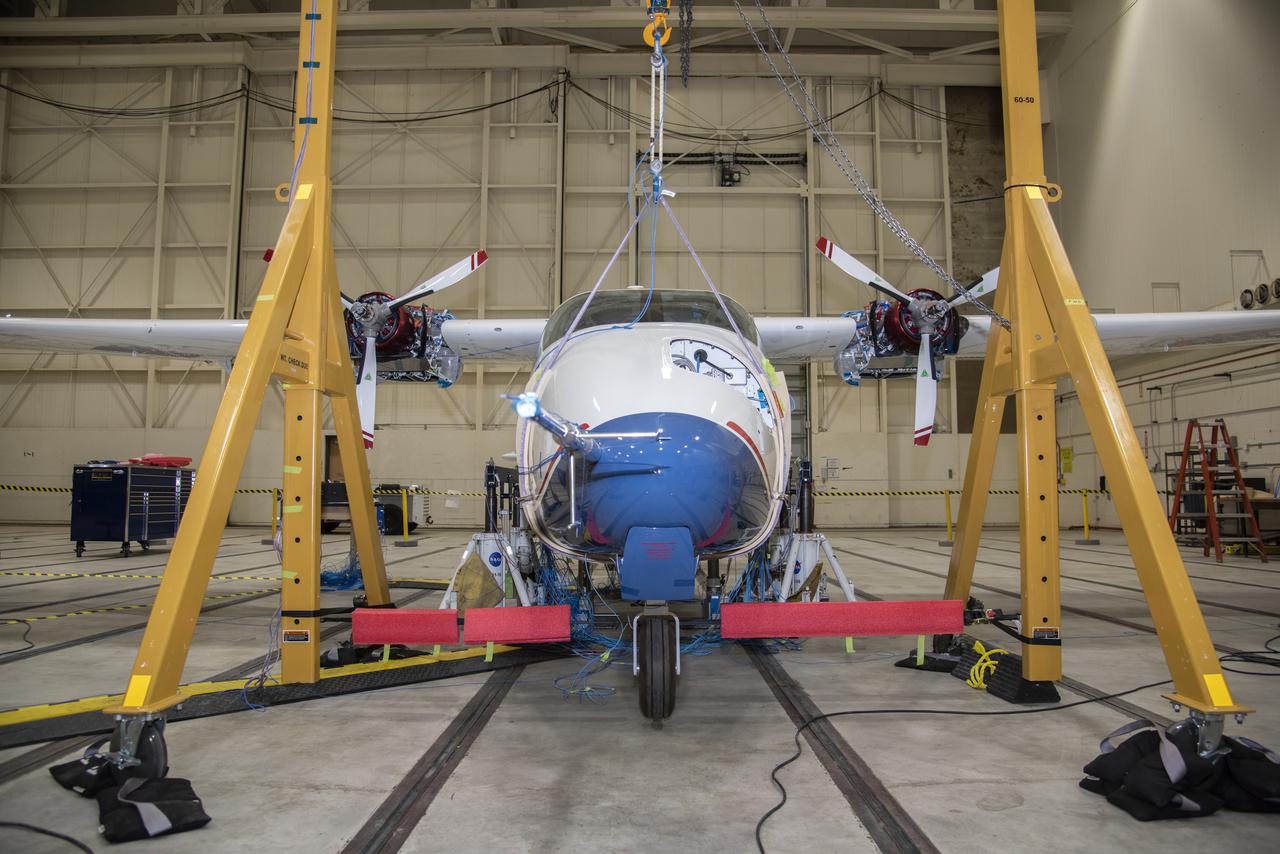
NASA’s all-electric X-57 Maxwell prepares for ground vibration testing, or GVT, at NASA’s Armstrong Flight Research Center in California. Done in parallel with cruise motor controller testing, the GVT tested the vehicle at various vibration levels, helping engineers to examine and validate the integrity of the vehicle for flight conditions. A goal of X-57 is to help the Federal Aviation Administration set certification standards for emerging electric aircraft markets.
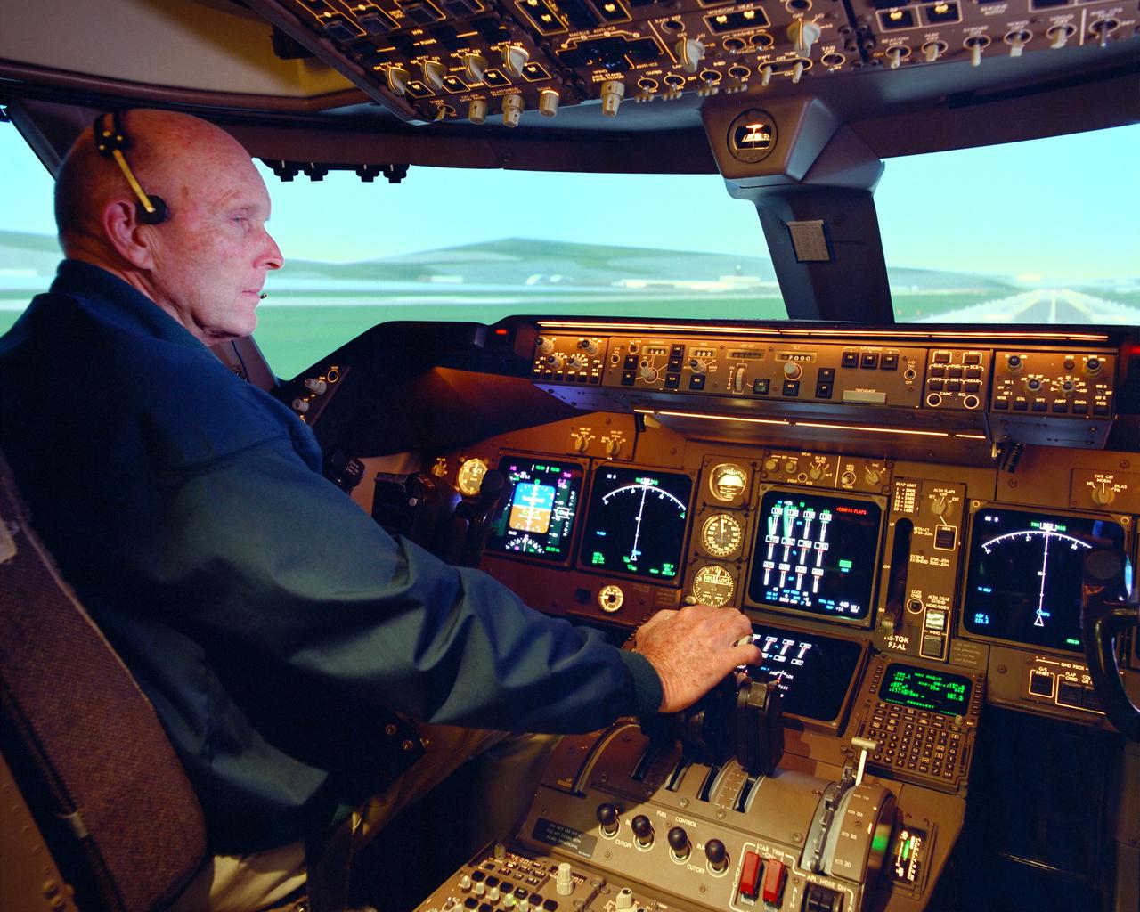
NASA research pilot Gordon Fullerton checked out how the PCA software worked in the multi-engine simulator at NASA Ames before fight-testing PCA in an MD-11.
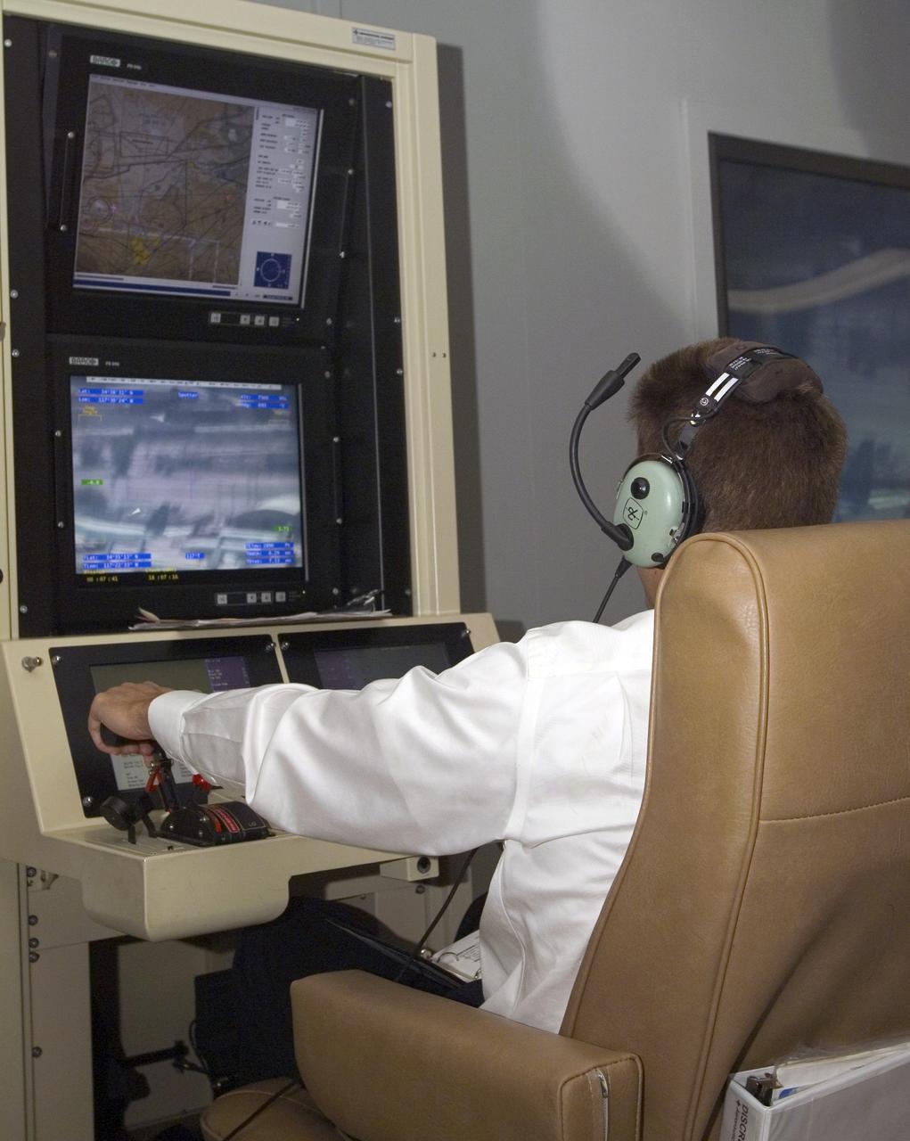
A pilot for General Atomics guides the Altair remotely operated aircraft from a ground control station using both visual and telemetered data.
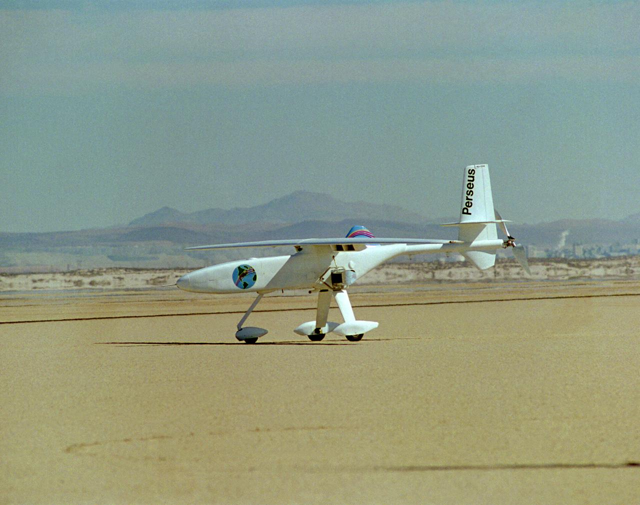
One of NASA's unmanned, remotely controlled aircraft, the Perseus B, is seen here before its first flight at the Dryden Flight Research Center, Edwards, California.
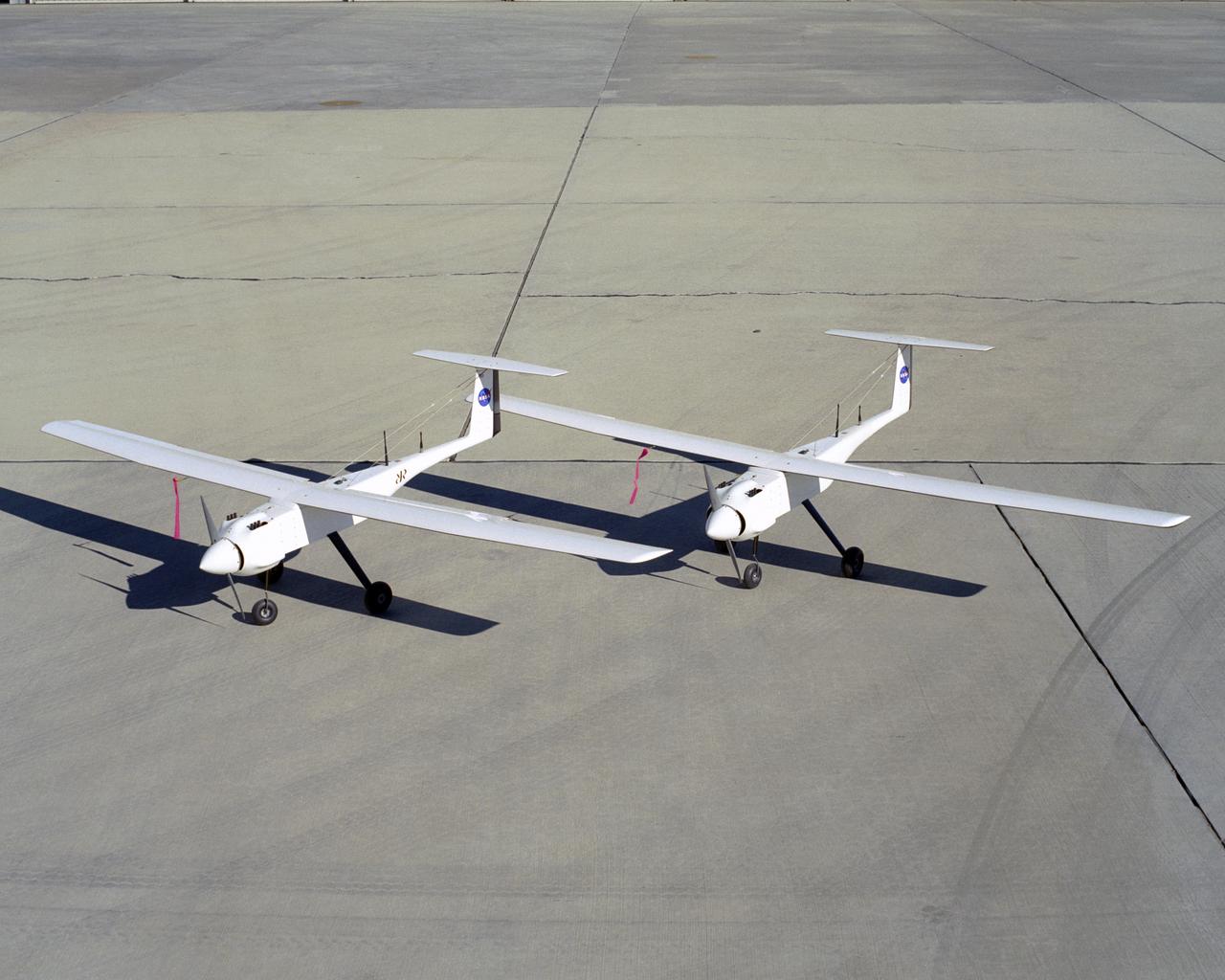
Two identical RnR Products APV-3 aircraft validated cooperative flight control software in the Networked UAV Teaming Experiment at NASA Dryden in early 2005.
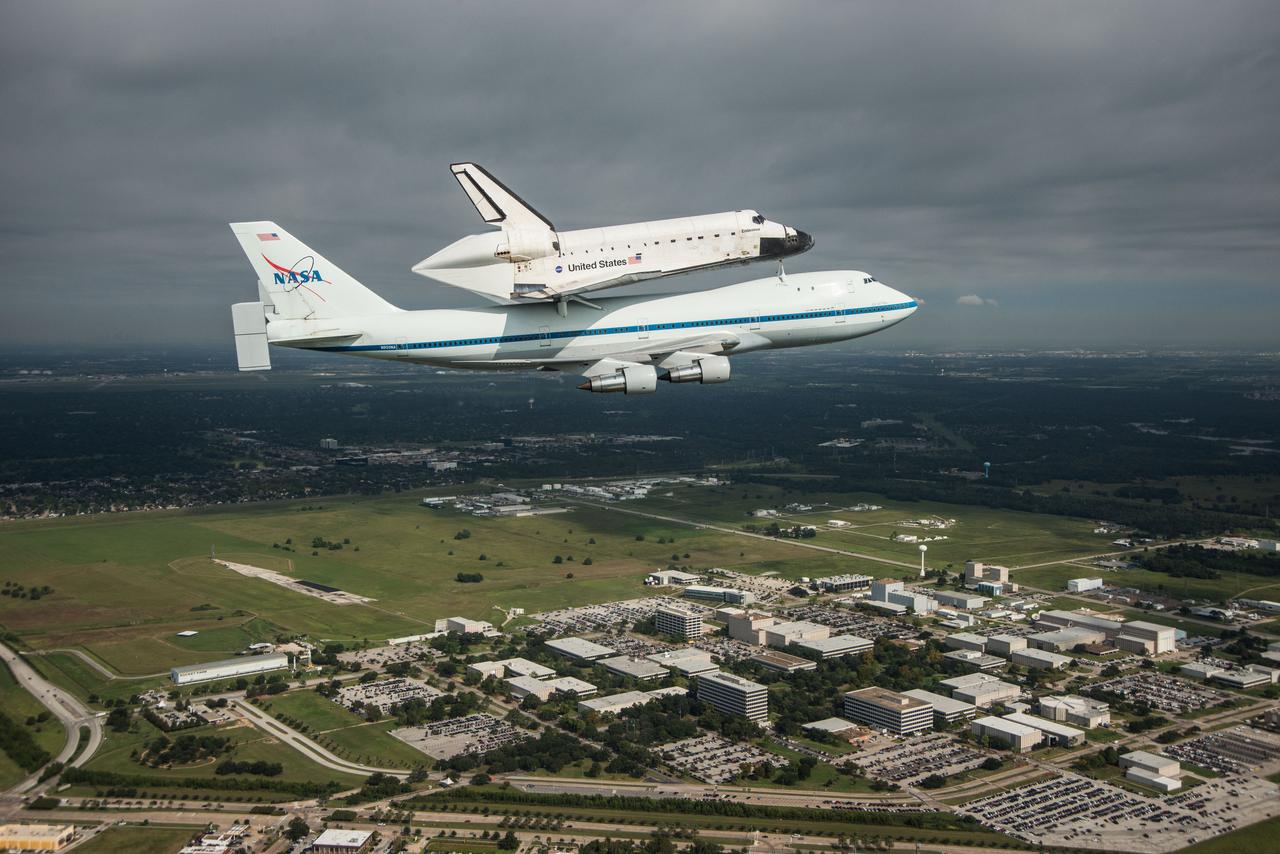
Space Shuttle Endeavour is ferried by NASA's Shuttle Carrier Aircraft (SCA) over the Johnson Space Center in Houston, Texas on September 19, 2012. NASA pilots Jeff Moultrie and Bill Rieke are at the controls of the Shuttle Carrier Aircraft. Photo taken by NASA photographer Sheri Locke in the backseat of a NASA T-38 chase plane with NASA pilot Thomas E. Parent at the controls. Photo Credit: NASA/ Sheri Locke
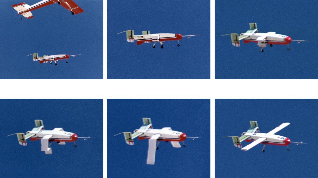
The deployable, inflatable wing technology demonstrator aircraft's wings begin deploying following separation from its carrier aircraft during a flight experiment conducted by the NASA Dryden Flight Research Center, Edwards, California. Wing deployment time is typically on the order of a third of a second, almost faster than the human eye can see. Three successful flights of the I2000 inflatable wing aircraft occurred. During the flights, the team air-launched the radio-controlled (R/C) I2000 from an R/C utility airplane at an altitude of 800-1000 feet. As the I2000 separated from the carrier aircraft, its inflatable wings "popped-out," deploying rapidly via an on-board nitrogen bottle. The aircraft remained stable as it transitioned from wingless to winged flight. The unpowered I2000 glided down to a smooth landing under complete control.
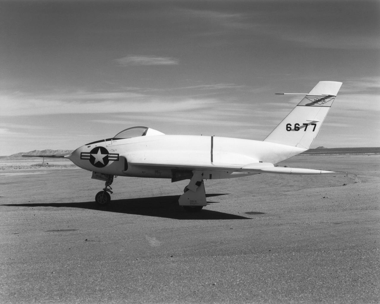
In this 1950 view of the left side of the NACA High-Speed Flight Research Station's X-4 research aircraft, the low swept wing and horizontal taillest design are seen. The X-4 Bantam, a single-place, low swept-wing, semi-tailless aircraft, was designed and built by Northrop Aircraft, Inc. It had no horizontal tail surfaces and its mission was to obtain in-flight data on the stability and control of semi-tailless aircraft at high subsonic speeds.
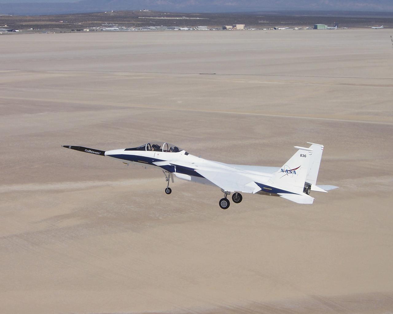
Approaching the runway after the first evaluation flight of the Quiet Spike project, NASA's F-15B testbed aircraft cruises over Roger's Dry Lakebed near the Dryden Flight Research Center. The Quiet Spike was developed by Gulfstream Aerospace as a means of controlling and reducing the sonic boom caused by an aircraft 'breaking' the sound barrier.
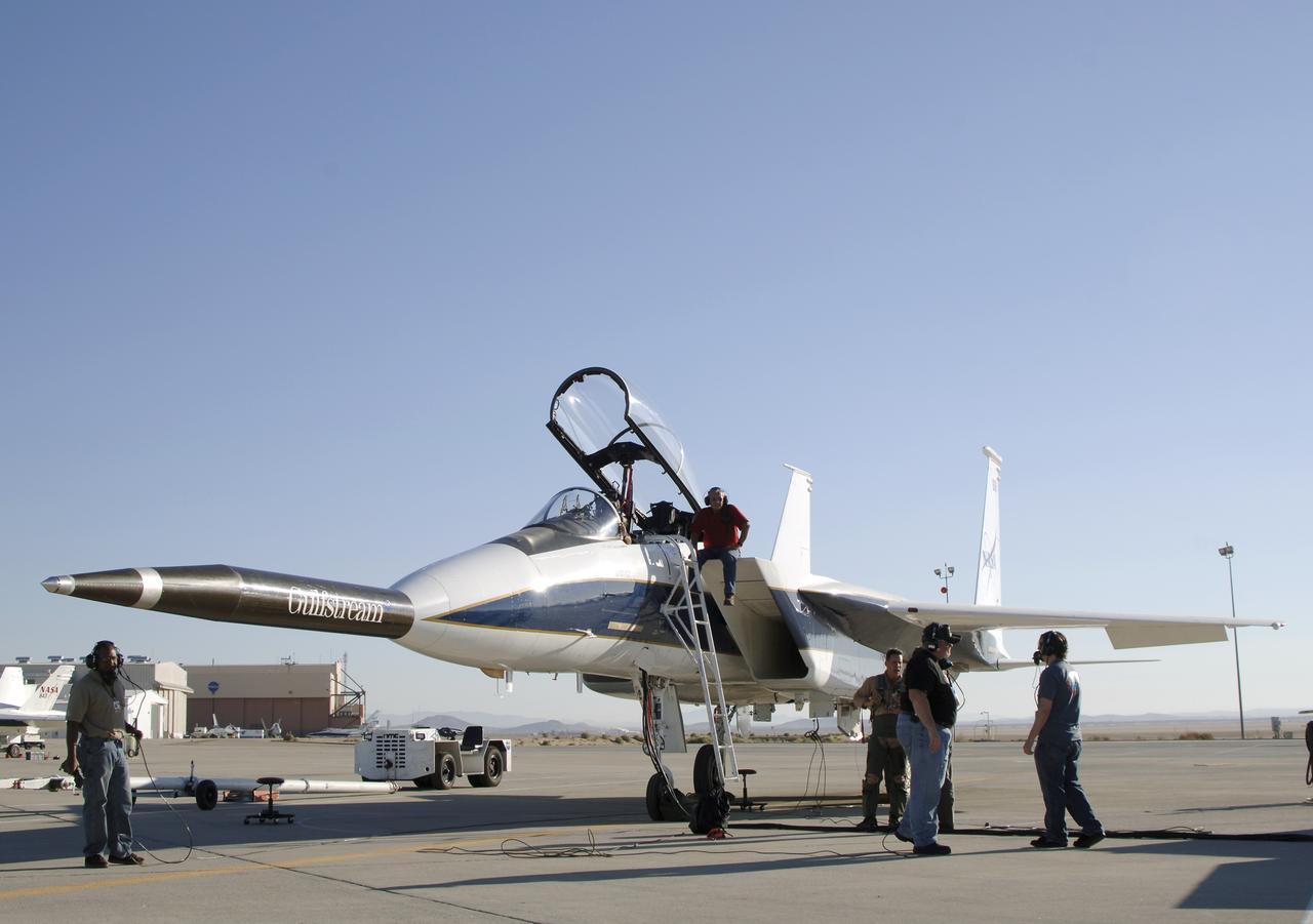
NASA's F-15B testbed aircraft undergoes pre-flight checks before performing the first flight of the Quiet Spike project. The first flight was performed for evaluation purposes, and the spike was not extended. The Quiet Spike was developed as a means of controlling and reducing the sonic boom caused by an aircraft 'breaking' the sound barrier.
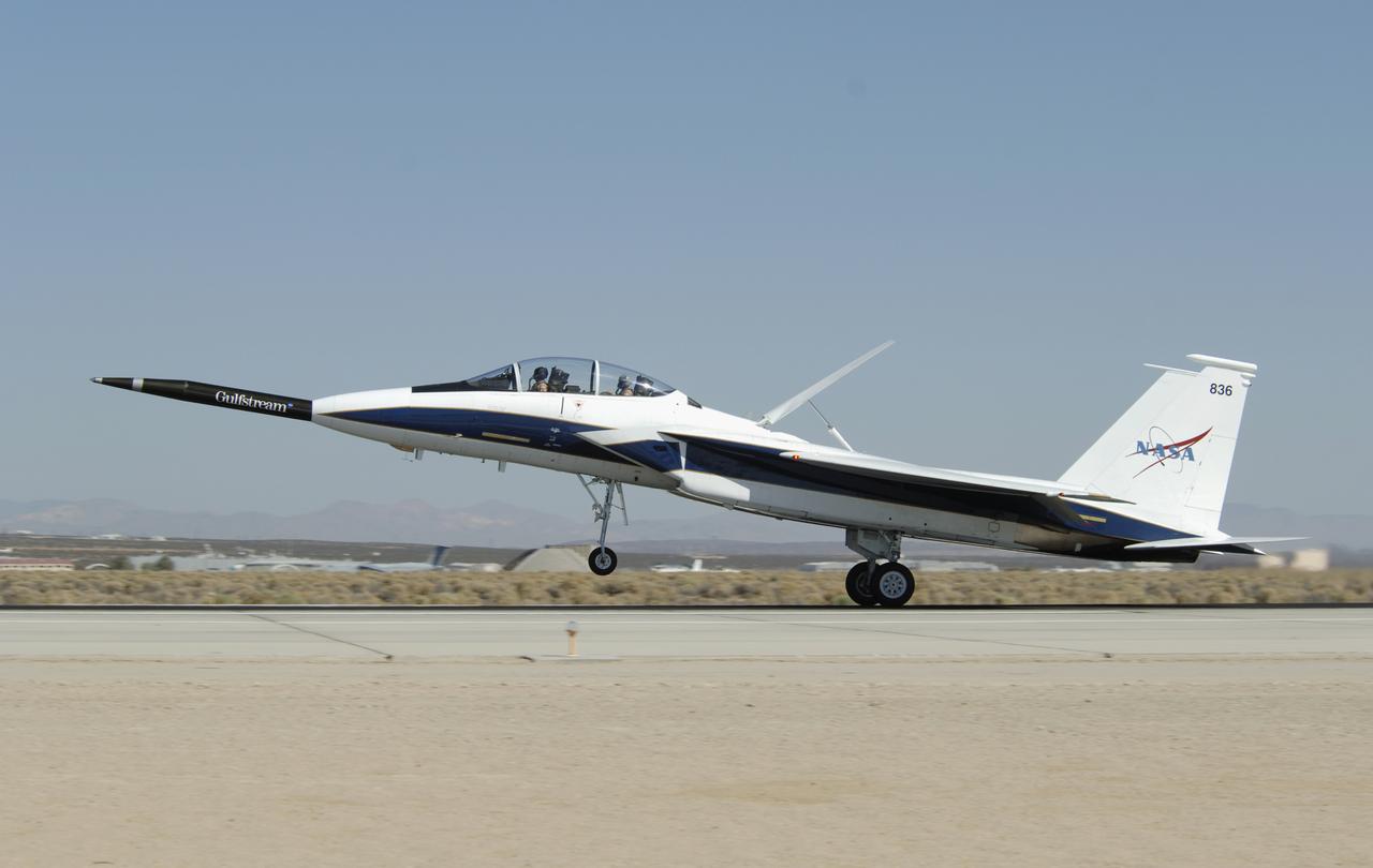
NASA's F-15B testbed aircraft lands after the first flight of the Quiet Spike project. The first flight was performed for evaluation purposes, and the spike was not extended. The Quiet Spike was developed as a means of controlling and reducing the sonic boom caused by an aircraft 'breaking' the sound barrier.

The communication antenna is used primarily for test flights to receive downlink flight data and video from test aircraft and also to support command uplink of data to test aircraft for command and control. It is one of two such assets of the Dryden Aeronautical Test Range at NASA’s Armstrong Flight Research Center in California.
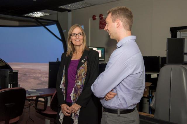
Jesse Brady, an early career NASA employee at NASA’s Armstrong Flight Research Center at Edwards, California, discusses a NASA aircraft simulation project with NASA Acting Deputy Chief Technologist Vicki Crisp. The simulation accesses aircraft controllability with limited pilot visibility, using only front view cameras and side windows.
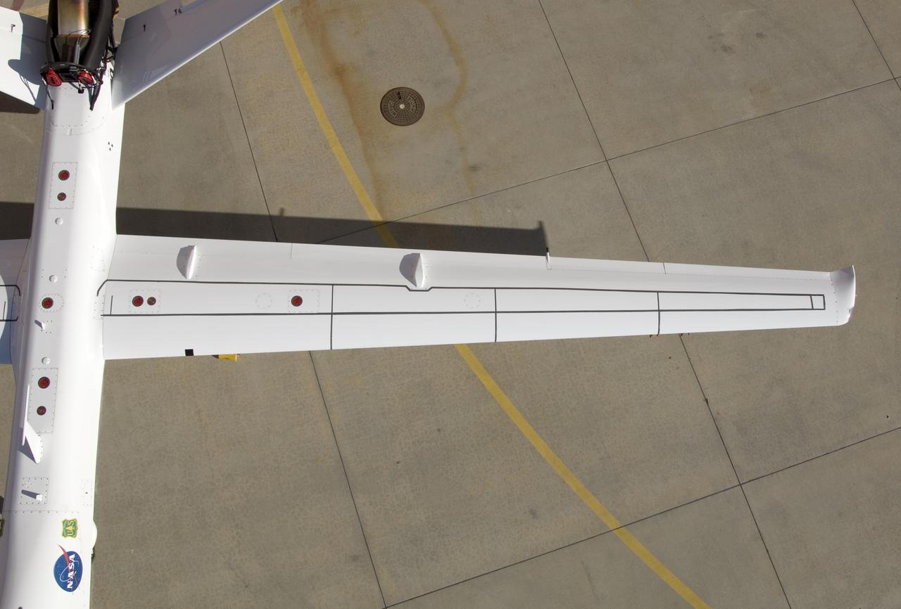
Although the new fiber optic sensors on the Ikhana, which are located on fibers that are the diameter of a human hair, are not visible, the sealant used to cover them can be seen in this view from above the left wing. NASA Dryden Flight Research Center is evaluating an advanced fiber optic-based sensing technology installed on the wings of NASA's Ikhana aircraft. The fiber optic system measures and displays the shape of the aircraft's wings in flight. There are other potential safety applications for the technology, such as vehicle structural health monitoring. If an aircraft structure can be monitored with sensors and a computer can manipulate flight control surfaces to compensate for stresses on the wings, structural control can be established to prevent situations that might otherwise result in a loss of control.
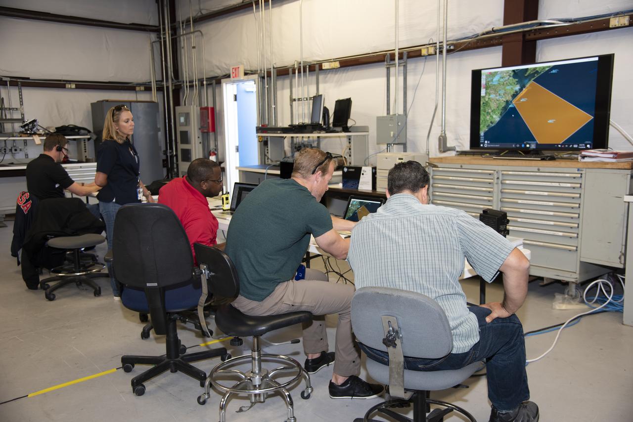
NASA mission controllers, engineers, pilots and communications specialists in the mission control room monitor the supersonic research flight off the coast of Galveston, as part of the QSF18 flight series. The flight operations crew tracks the status of the flights, maintains communications with the aircraft, communicates with U.S. Coast Guard, and coordinates community feedback data.

NASA mission controllers, engineers, pilots and communications specialists in the mission control room monitor the supersonic research flight off the coast of Galveston, as part of the QSF18 flight series. The flight operations crew tracks the status of the flights, maintains communications with the aircraft, communicates with U.S. Coast Guard, and coordinates community feedback data.
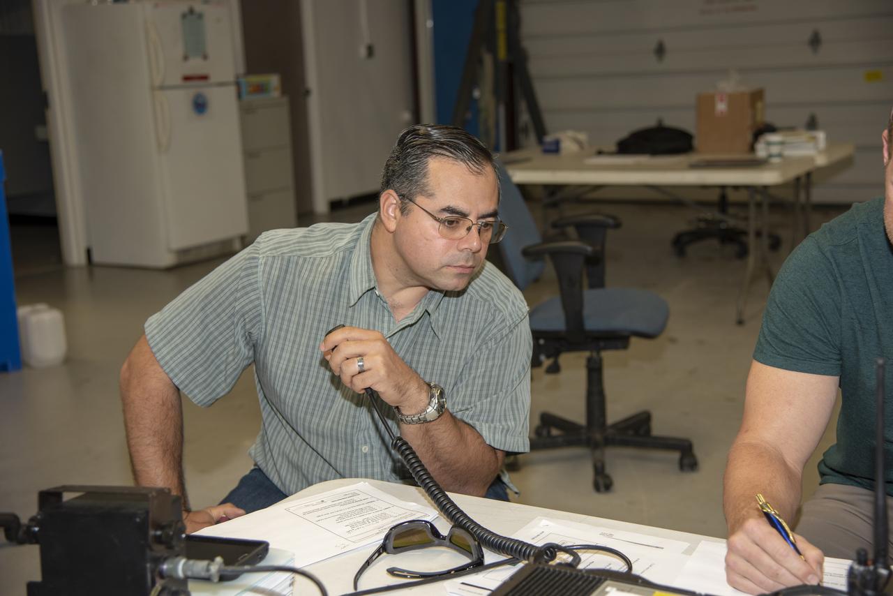
NASA mission controllers, engineers, pilots and communications specialists in the mission control room monitor the supersonic research flight off the coast of Galveston, as part of the QSF18 flight series. The flight operations crew tracks the status of the flights, maintains communications with the aircraft, communicates with U.S. Coast Guard, and coordinates community feedback data.