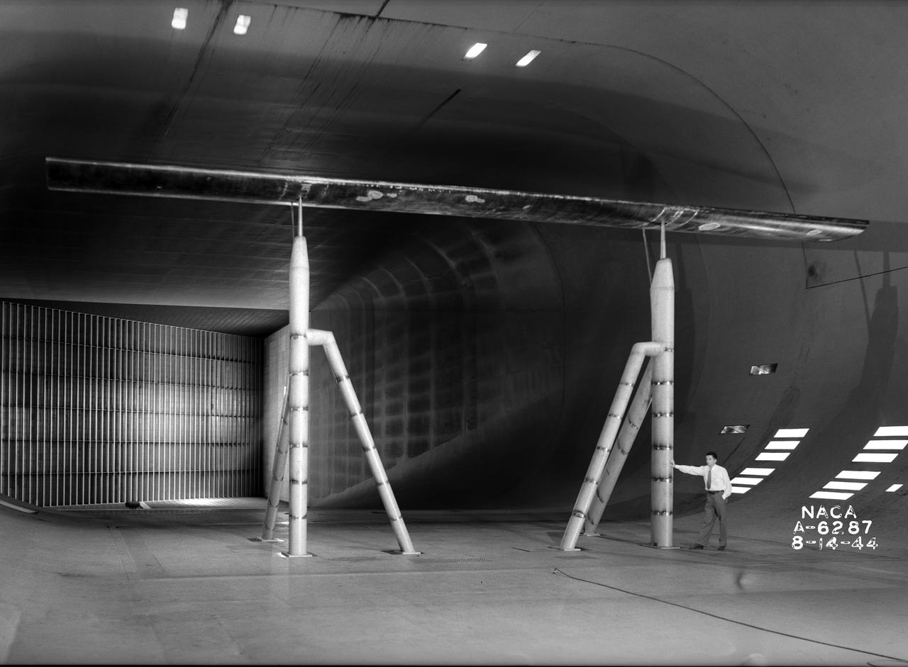
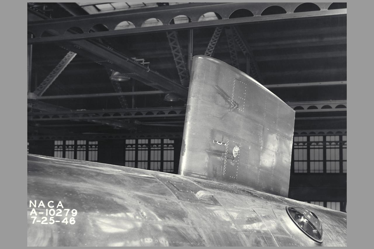
Clark Y Airfoil. 3/4 front view of 8x48 foot Clark Y Airfoil mounted (inverted) in the 40x80 foot wind tunnel at NACA's Ames Research Center.

Particle-image velocimetry (PIV) is performed on the upper surface of a pitching airfoil in the NASA Glenn Icing Research Tunnel. PIV is a laser-based flow velocity measurement technique used widely in wind tunnels. These experiments were conducted as part of a research project focused on enhancing rotorcraft speed, efficiency and maneuverability by suppressing dynamic stall.
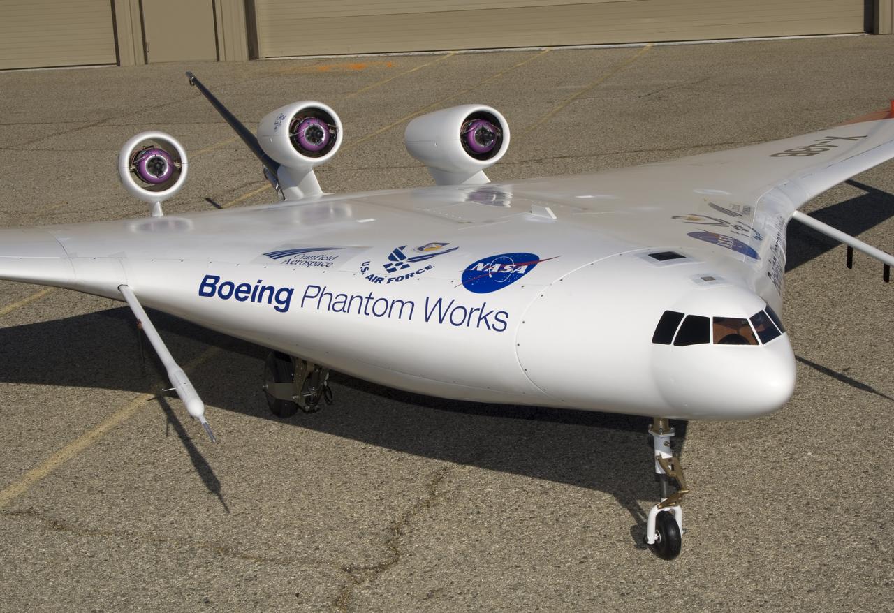
This closeup of Boeing Phantom Works' unique X-48B Blended Wing Body technology demonstrator shows off its unusual engine placement and supercritical airfoil.
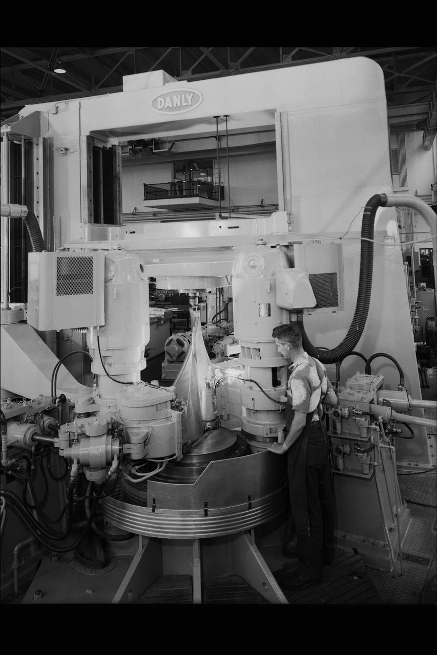
DANLY AIRFOIL CUTTING MACHINE.
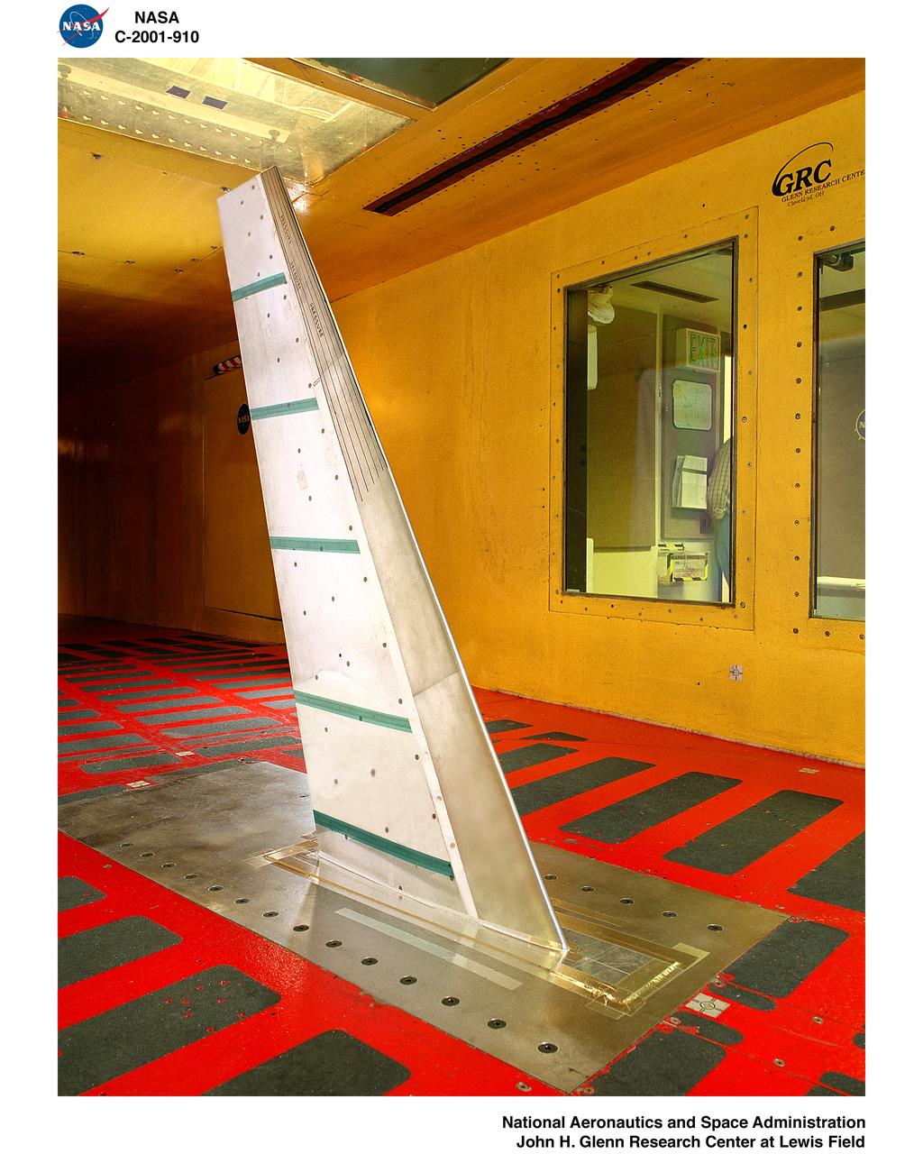
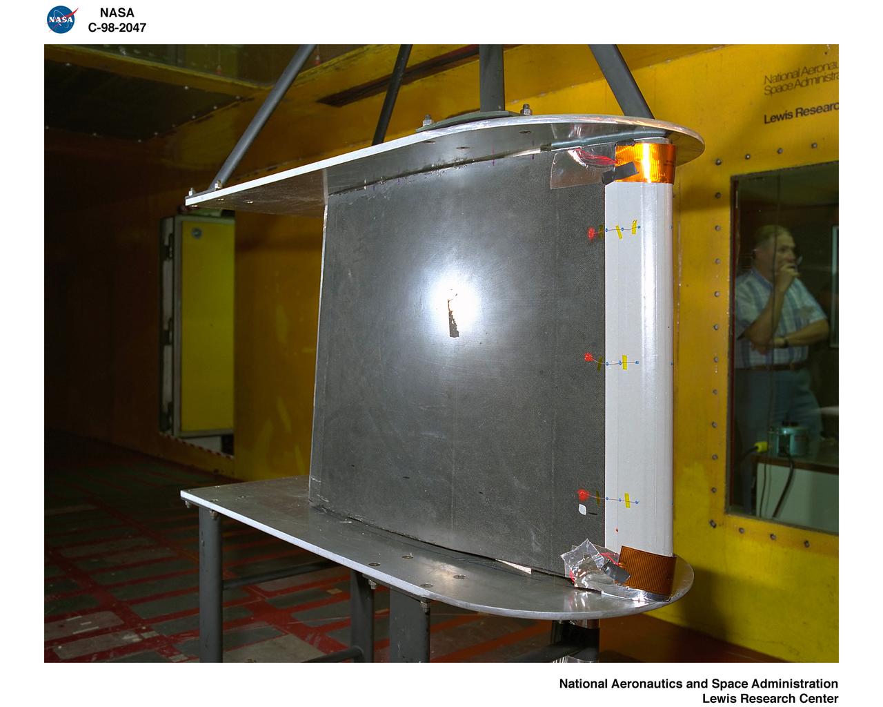
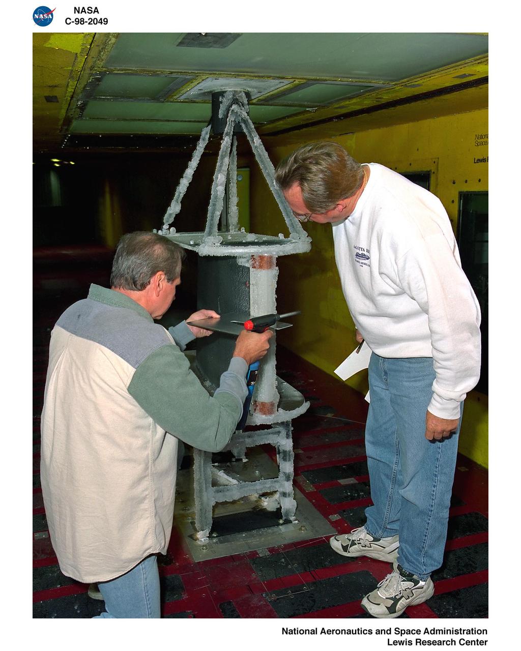
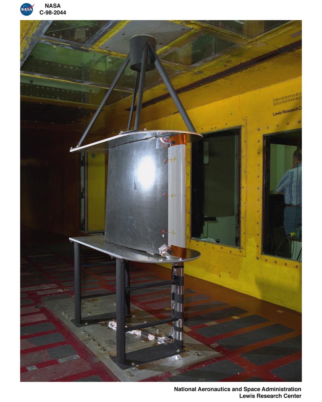
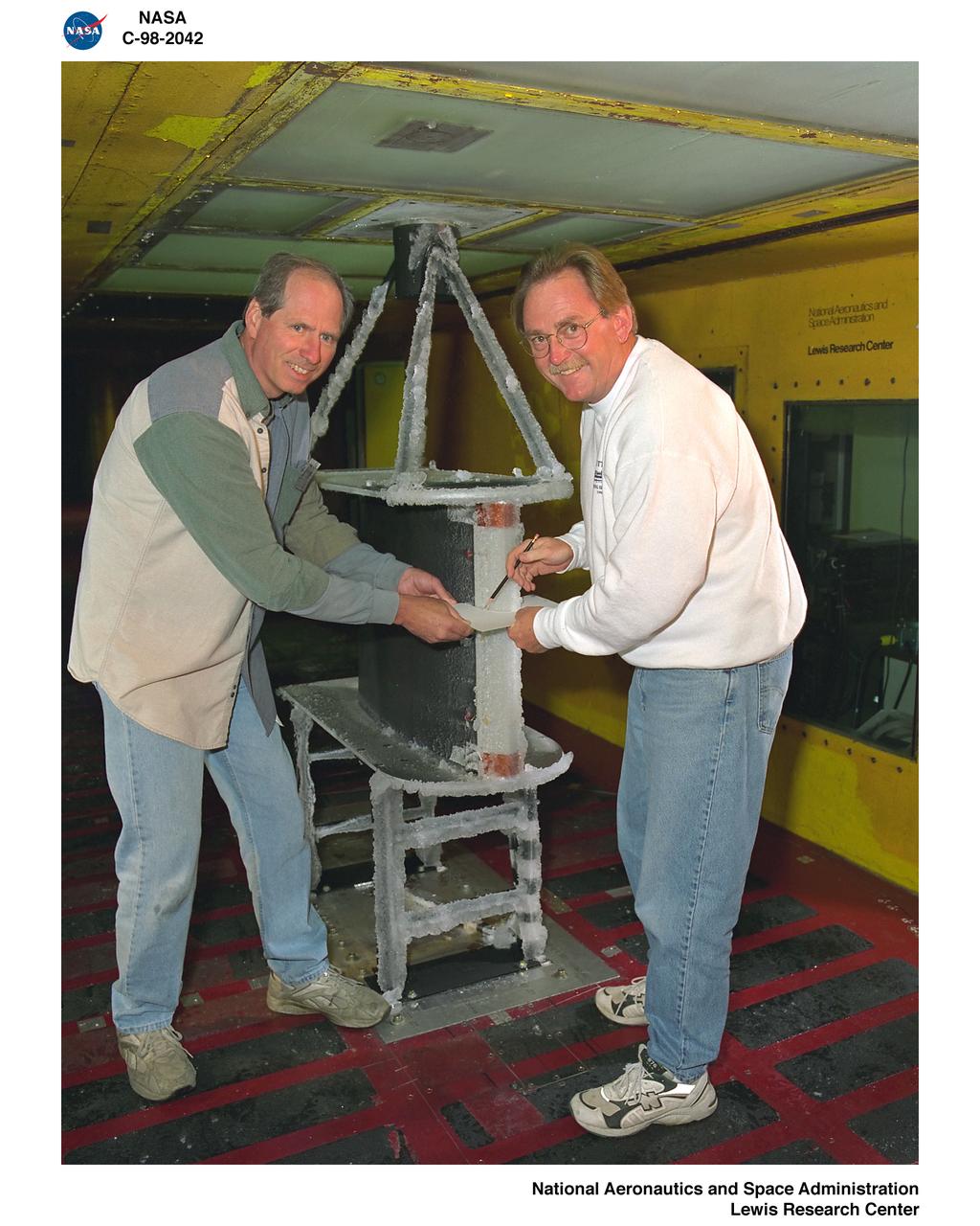
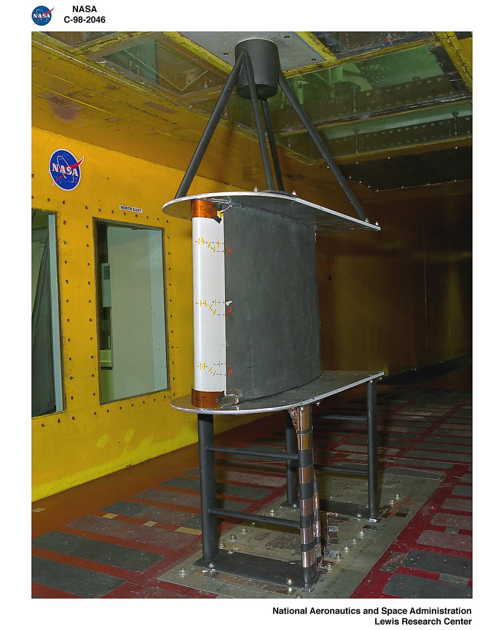
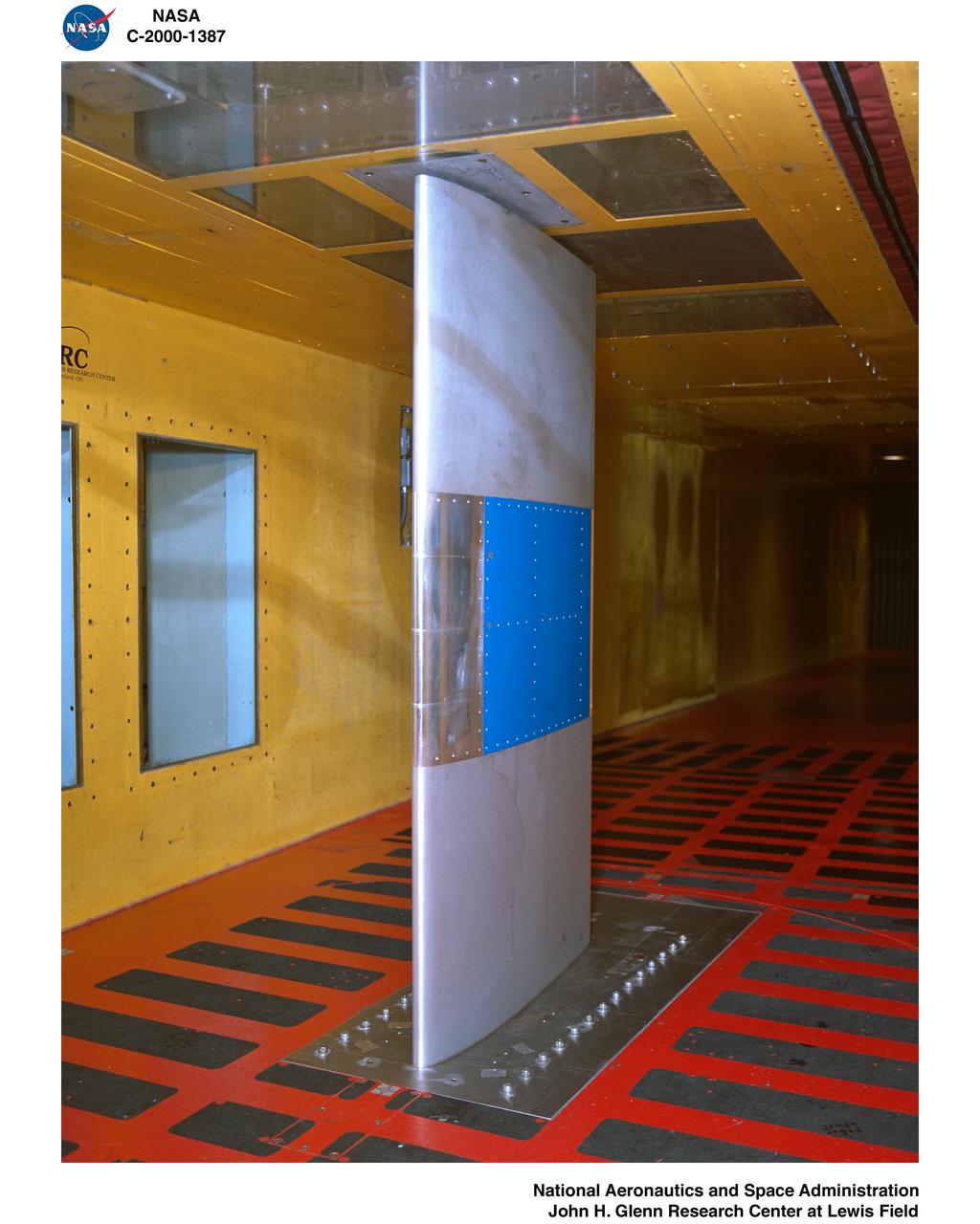
SWEPT GLC305 AIRFOIL TEST
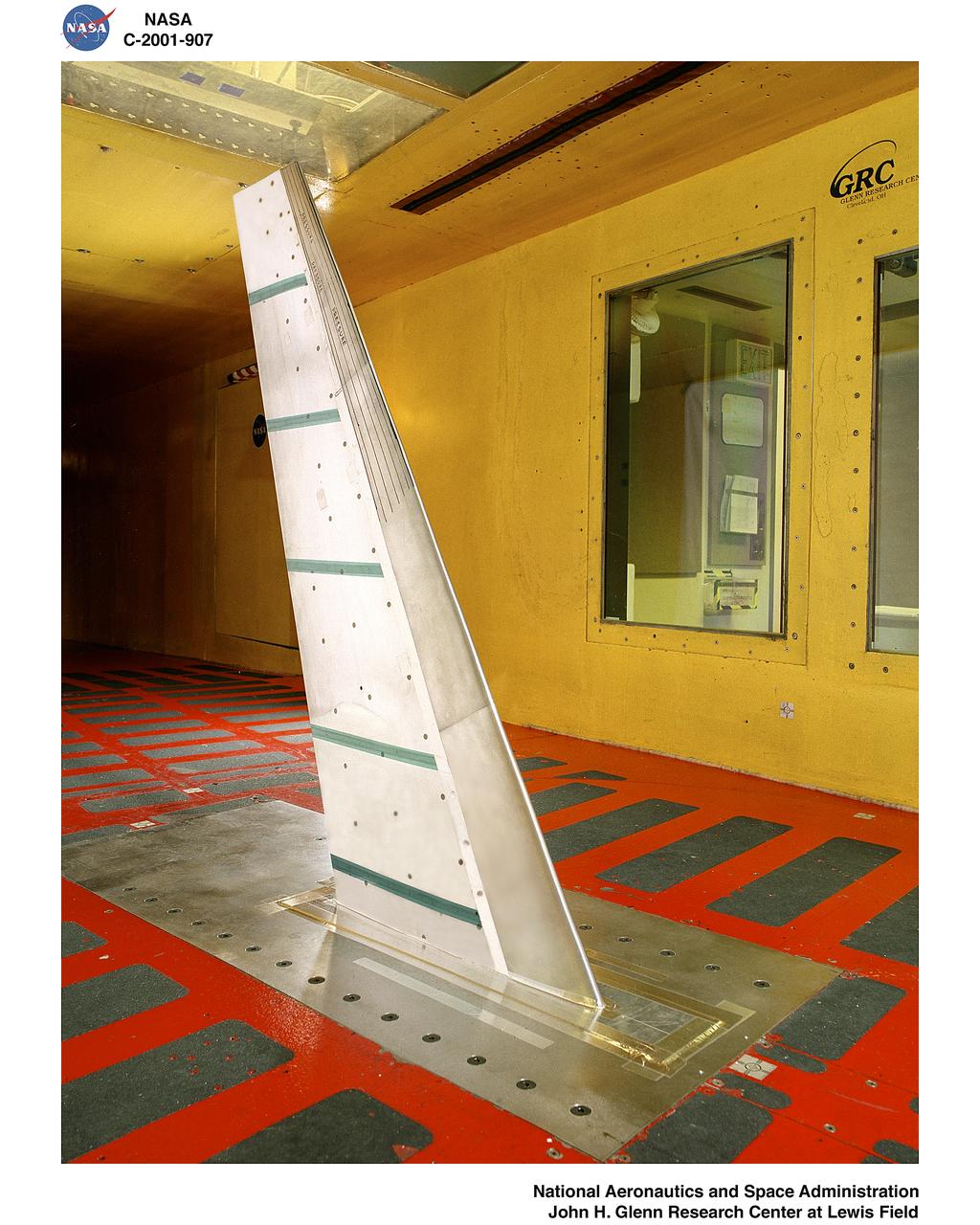
SWEPT GLC305 AIRFOIL TEST
LANCAIR AIRFOIL THERMO ICE PROTECTION
LANCAIR AIRFOIL THERMO ICE PROTECTION
LANCAIR AIRFOIL THERMO ICE PROTECTION
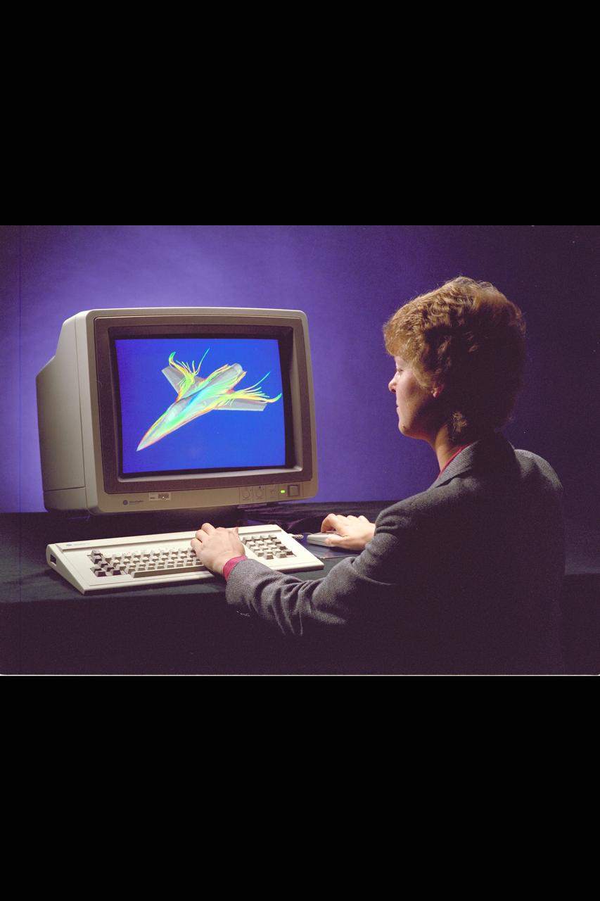
Iris Workstation with CFD CGI airfoil

LANCAIR AIRFOIL THERMO ICE PROTECTION
LANCAIR AIRFOIL THERMO ICE PROTECTION
LANCAIR AIRFOIL THERMO ICE PROTECTION
NACA Photographer Electrically heated airfoil - wing glove on C-46 airplane
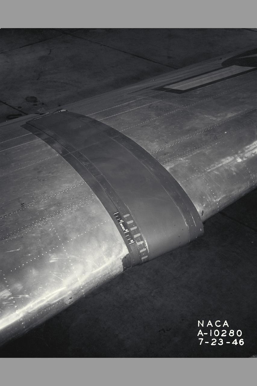
NACA Photographer Electrically heated airfoil - wing glove on C-46 airplane
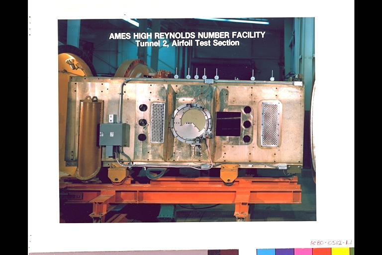
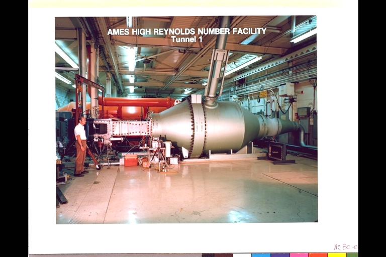
N-231 High Reynolds Number Channel Facility (Tunnel 2, Airfoil Test Section)
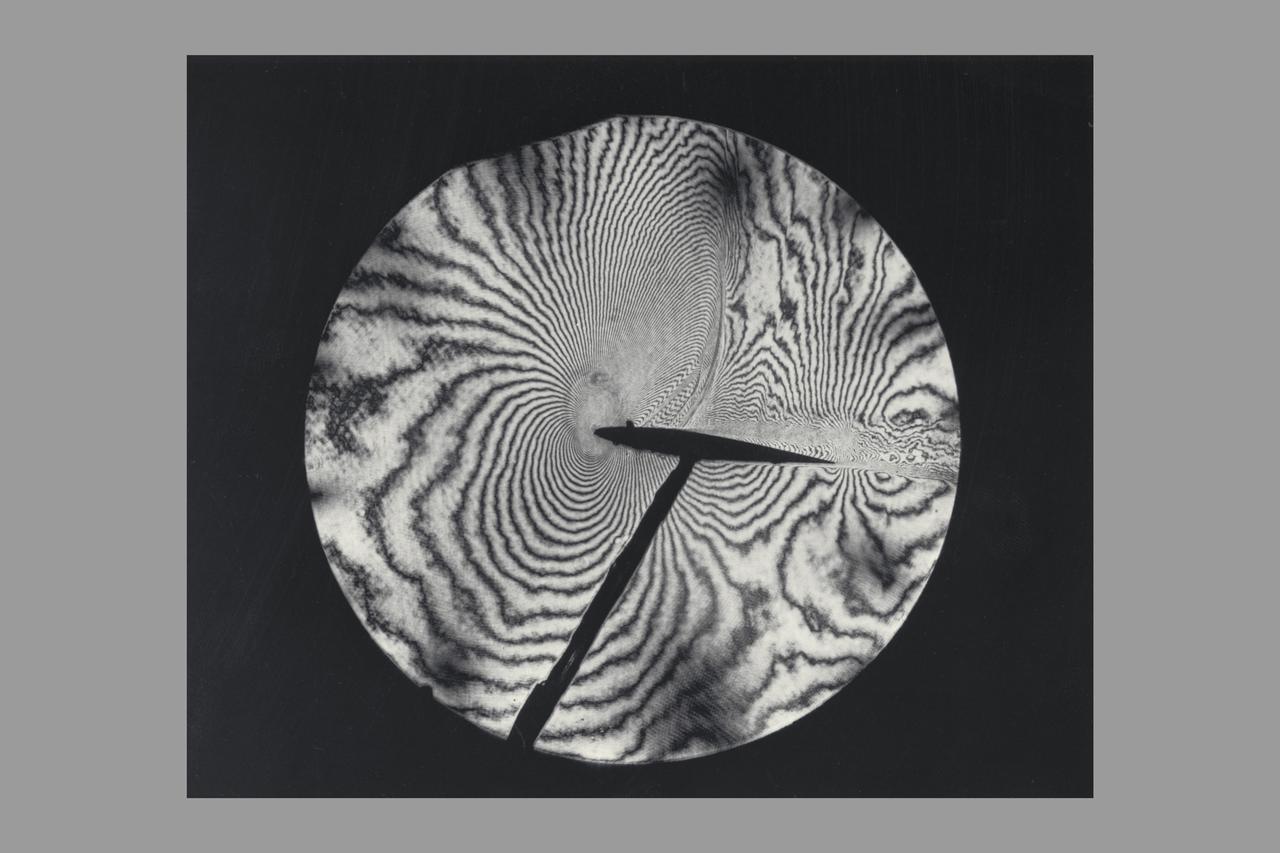
Interferogram of Transonic flow field - reconstructed laser hologram as an infinite-fringe interferogram shows shock-wave shape, location and separaton of the airfoil boundry layer
POST TEST FOR THE NATIONAL ADVISORY COMMITTEE FOR AERONAUTICS NACA 12 INCH AND 36 INCH CHORD 0012 AIRFOIL ABRASIONS TO SURFACE FOR FACILITY STANDARDIZATION
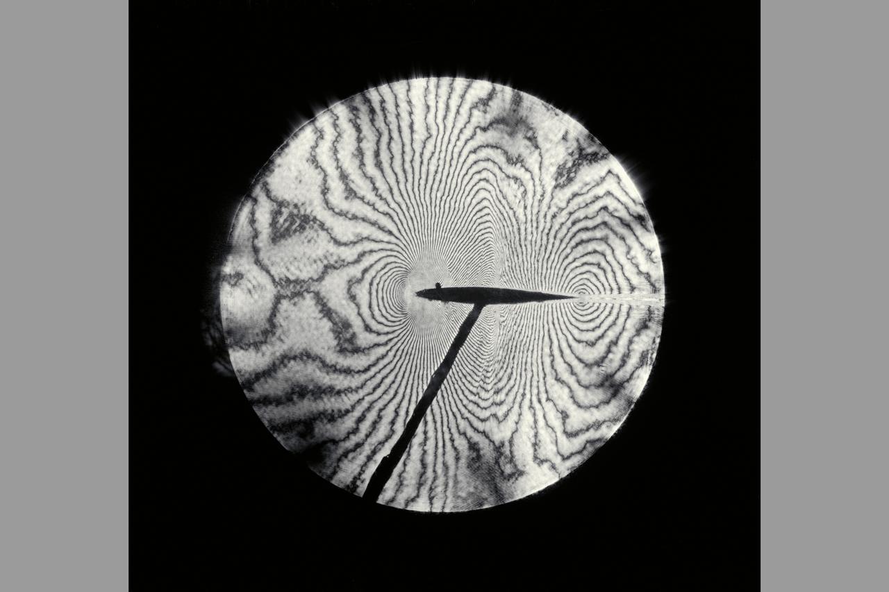
Interferogram of Transonic flow field - reconstructed laser hologram as an infinite-fringe interferogram shows shock-wave shape, location and separaton of the airfoil boundry layer
N-231 High Reynolds Number Channel II Facility In this timeframe the test section was designed specifically to test two-dimensional airfoil models. It is equipped with 'through-the-wall' turntables that remotely position the airfoil, with flexible upper and lower walls that can be adjusted to minimize wall interference. Porous side-wall panels provide boundary-layer removal.
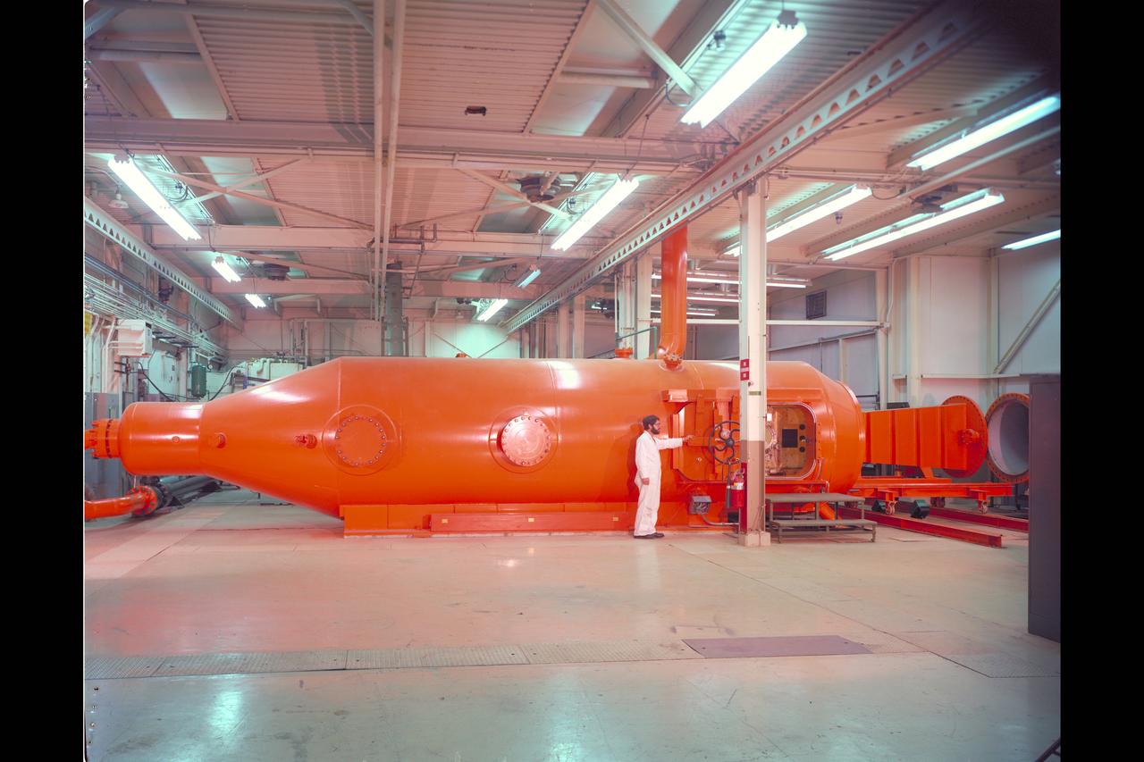
N-231 High Reynolds Number Channel Facility (An example of a Versatile Wind Tunnel) Tunnel 1 I is a blowdown Facility that utilizes interchangeable test sections and nozzles. The facility provides experimental support for the fluid mechanics research, including experimental verification of aerodynamic computer codes and boundary-layer and airfoil studies that require high Reynolds number simulation. (Tunnel 1)
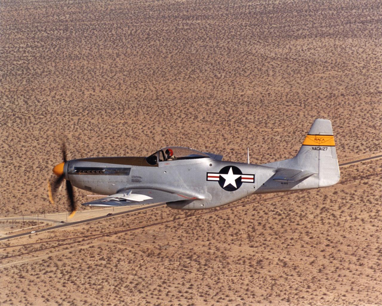
A white plate on the top of the wing of a restored National Advisory Committee for Aeronautics (NACA) P-51D Mustang mounts scale airfoil shapes as used by the NACA in the late 1940s for high-speed research. This former NACA testbed Mustang was rebuilt by John Muszala for Bill Allmon of Las Vegas, Nevada, who has been flying it since 1998. Allmon flew the vintage fighter to NASA's Dryden Flight Research Center at Edwards, California, Sept. 15, 2000 for a reunion of former NACA employees.
Long, thin, high-aspect-ratio wings are considered crucial to the design of future long-range aircraft, including fuel-efficient airliners and cargo transports. Unlike the short, stiff wings found on most aircraft today, slender, flexible airfoils are susceptible to uncontrollable vibrations, known as flutter, and may be stressed by bending forces from wind gusts and atmospheric turbulence. To improve ride quality, efficiency, safety, and the long-term health of flexible aircraft structures, NASA is using the X-56A Multi-Utility Technology Testbed (MUTT) to investigate key technologies for active flutter suppression and gust-load alleviation.
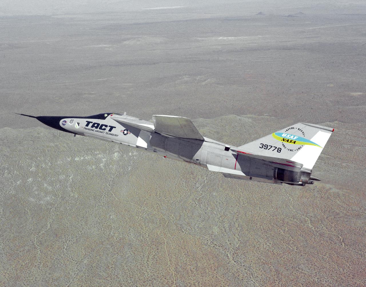
The General Dynamics TACT/F-111A Aardvark is seen In a banking-turn over the California Mojave desert. This photograph affords a good view of the supercritical wing airfoil shape. Starting in 1971 the NASA Flight Research Center and the Air Force undertook a major research and flight testing program, using F-111A (#63-9778), which would span almost 20 years before completion. Intense interest over the results coming from the NASA F-8 supercritical wing program spurred NASA and the Air Force to modify the General Dynamics F-111A to explore the application of supercritical wing technology to maneuverable military aircraft. This flight program was called Transonic Aircraft Technology (TACT).
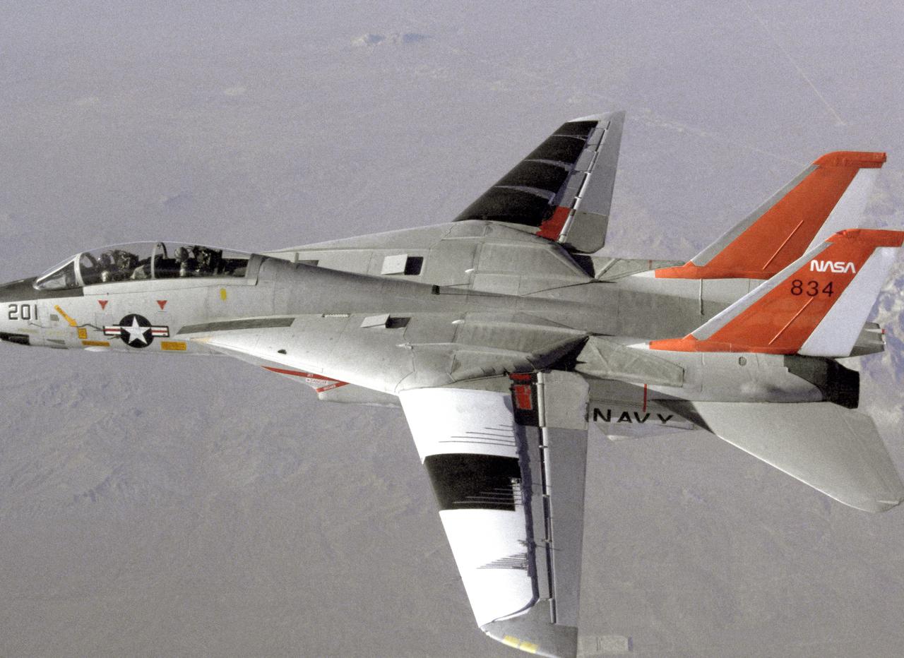
NASA 834, an F-14 Navy Tomcat, seen here in flight, was used at Dryden in 1986 and 1987 in a program known as the Variable-Sweep Transition Flight Experiment (VSTFE). This program explored laminar flow on variable sweep aircraft at high subsonic speeds. An F-14 aircraft was chosen as the carrier vehicle for the VSTFE program primarily because of its variable-sweep capability, Mach and Reynolds number capability, availability, and favorable wing pressure distribution. The variable sweep outer-panels of the F-14 aircraft were modified with natural laminar flow gloves to provide not only smooth surfaces but also airfoils that can produce a wide range of pressure distributions for which transition location can be determined at various flight conditions and sweep angles. Glove I, seen here installed on the upper surface of the left wing, was a "cleanup" or smoothing of the basic F-14 wing, while Glove II was designed to provide specific pressure distributions at Mach 0.7. Laminar flow research continued at Dryden with a research program on the NASA 848 F-16XL, a laminar flow experiment involving a wing-mounted panel with millions of tiny laser cut holes drawing off turbulent boundary layer air with a suction pump.
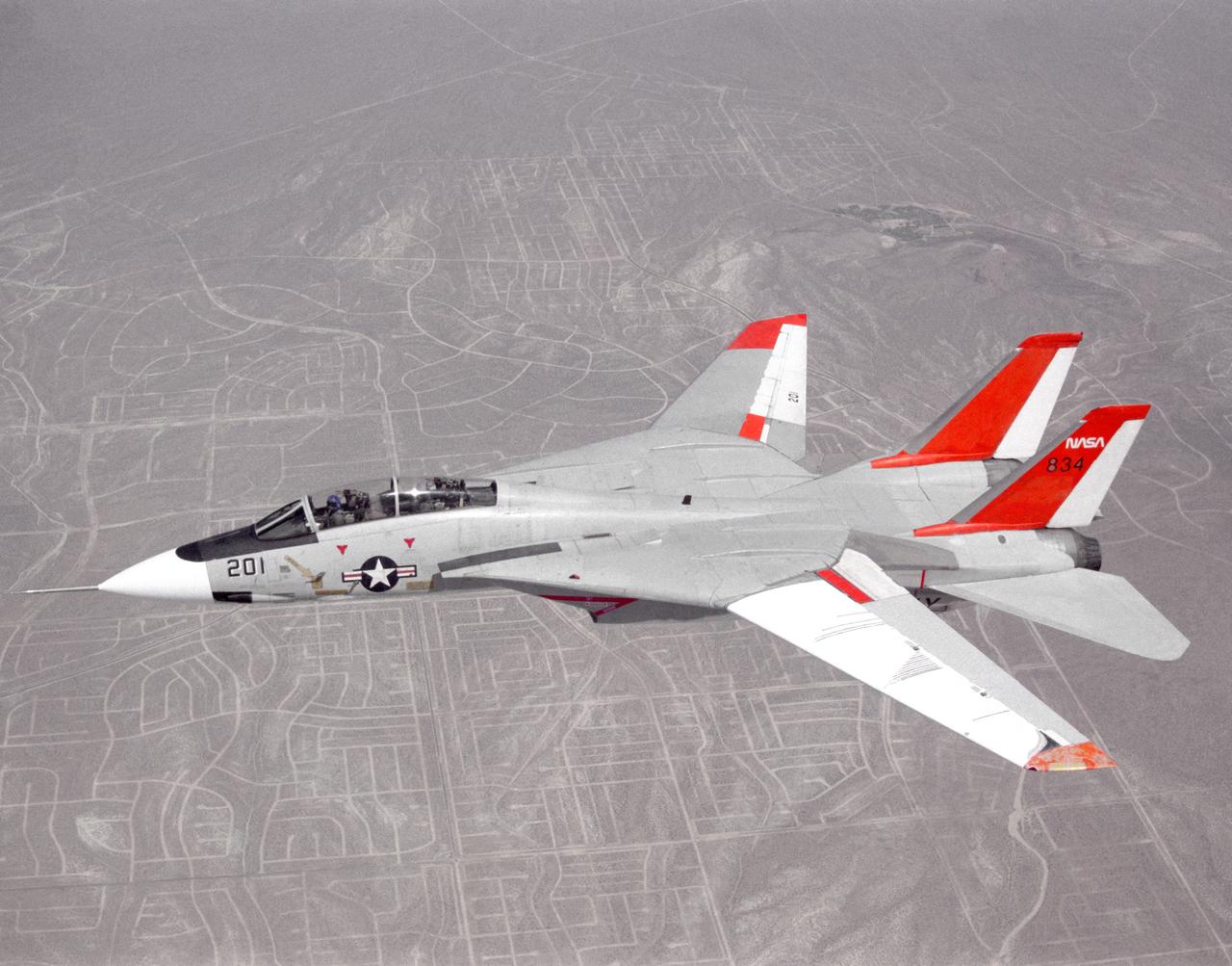
NASA 834, an F-14 Navy Tomcat, seen here in flight, was used at Dryden in 1986 and 1987 in a program known as the Variable-Sweep Transition Flight Experiment (VSTFE). This program explored laminar flow on variable sweep aircraft at high subsonic speeds. An F-14 aircraft was chosen as the carrier vehicle for the VSTFE program primarily because of its variable-sweep capability, Mach and Reynolds number capability, availability, and favorable wing pressure distribution. The variable sweep outer-panels of the F-14 aircraft were modified with natural laminar flow gloves to provide not only smooth surfaces but also airfoils that can produce a wide range of pressure distributions for which transition location can be determined at various flight conditions and sweep angles. Glove I, seen here installed on the upper surface of the left wing, was a "cleanup" or smoothing of the basic F-14 wing, while Glove II was designed to provide specific pressure distributions at Mach 0.7. Laminar flow research continued at Dryden with a research program on the NASA 848 F-16XL, a laminar flow experiment involving a wing-mounted panel with millions of tiny laser cut holes drawing off turbulent boundary layer air with a suction pump.
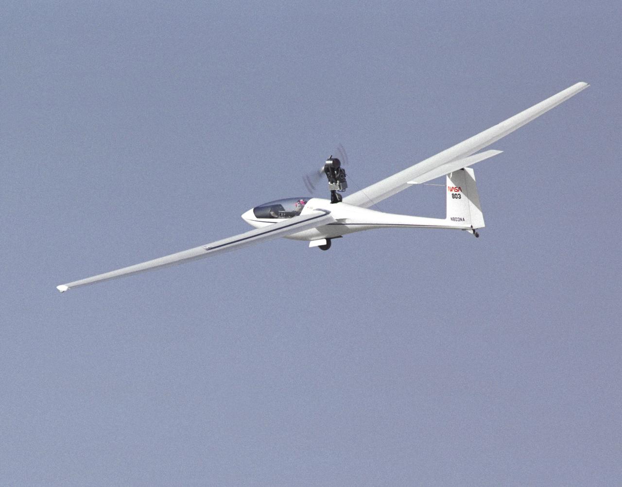
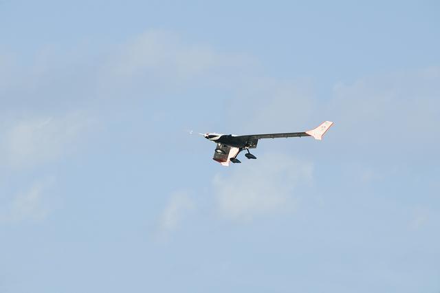
This photo shows NASA's PIK-20E motor-glider sailplane during a research flight from the Ames-Dryden Flight Research Facility (later, the Dryden Flight Research Center), Edwards, California, in 1991.
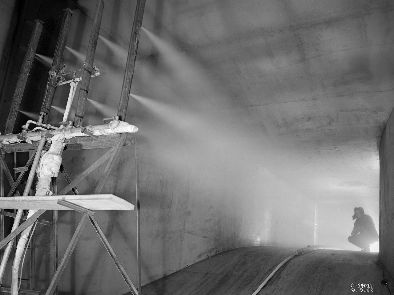
The spray bar system introduces water droplets into the Icing Research Tunnel’s air stream at the National Advisory Committee for Aeronautics (NACA) Lewis Flight Propulsion Laboratory. The icing tunnel was designed in the early 1940s to study ice accretion on airfoils and models. The Carrier Corporation designed a refrigeration system that reduced temperatures to -45° F. The tunnel’s drive fan generated speeds up to 400 miles per hour. The uniform injection of water droplets to the air was a key element of the facility’s operation. The system had to generate small droplets, distribute them uniformly throughout the airstream, and resist freezing and blockage. The Icing Research Tunnel’s designers struggled to develop a realistic spray system because they did not have access to data on the size of naturally occurring water droplets. For five years a variety of different designs were painstakingly developed and tested before the system was perfected. This photograph shows one of the trials using eight air-atomizing nozzles placed 48 feet upstream from the test section. A multi-cylinder device measured the size, liquid content, and distribution of the water droplets. The final system that was put into operation in 1950 included six horizontal spray bars with 80 nozzles that produced a 4- by 4-foot cloud in the test section. The Icing Research Tunnel produced excellent data throughout the 1950s and provided the basis for a hot air anti-icing system used on many transport aircraft.
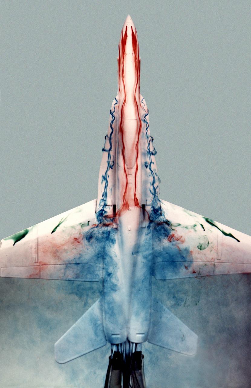
This image shows a plastic 1/48-scale model of an F-18 aircraft inside the "Water Tunnel" more formally known as the NASA Dryden Flow Visualization Facility. Water is pumped through the tunnel in the direction of normal airflow over the aircraft; then, colored dyes are pumped through tubes with needle valves. The dyes flow back along the airframe and over the airfoils highlighting their aerodynamic characteristics. The aircraft can also be moved through its pitch axis to observe airflow disruptions while simulating actual flight at high angles of attack. The Water Tunnel at NASA's Dryden Flight Research Center, Edwards, CA, became operational in 1983 when Dryden was a Flight Research Facility under the management of the Ames Research Center in Mountain View, CA. As a medium for visualizing fluid flow, water has played a significant role. Its use dates back to Leonardo da Vinci (1452-1519), the Renaissance Italian engineer, architect, painter, and sculptor. In more recent times, water tunnels have assisted the study of complex flows and flow-field interactions on aircraft shapes that generate strong vortex flows. Flow visualization in water tunnels assists in determining the strength of vortices, their location, and possible methods of controlling them. The design of the Dryden Water Tunnel imitated that of the Northrop Corporation's tunnel in Hawthorne, CA. Called the Flow Visualization Facility, the Dryden tunnel was built to assist researchers in understanding the aerodynamics of aircraft configured in such a way that they create strong vortex flows, particularly at high angles of attack. The tunnel provides results that compare well with data from aircraft in actual flight in another fluid-air. Other uses of the tunnel have included study of how such flight hardware as antennas, probes, pylons, parachutes, and experimental fixtures affect airflow. The facility has also been helpful in finding the best locations for emitting smoke from flight vehicles for flow vi
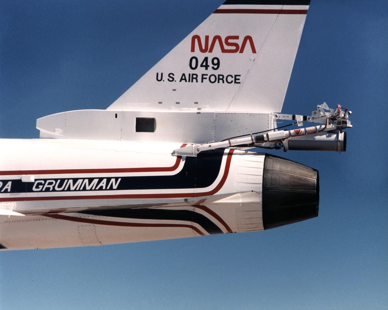
Because the number two X-29 at NASA's Ames-Dryden Flight Research Facility (later the Dryden Flight Research Center) flew at higher angles of attack than the number one aircraft, it required a spin chute system for safety. The system deployed a parachute for recovery of the aircraft if it inadvertently entered an uncontrolled spin. Most of the components of the spin chute system were located on a truss at the aft end of the aircraft. In addition, there were several cockpit modifications to facilitate use of the chute. The parachute was made of nylon and was of the conical ribbon type.
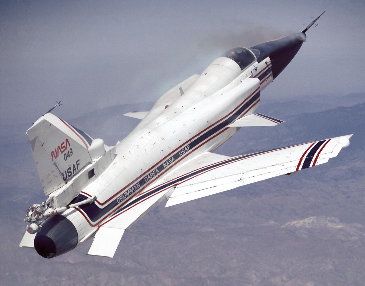
This photo shows the X-29 during a 1991 research flight. Smoke generators in the nose of the aircraft were used to help researchers see the behavior of the air flowing over the aircraft. The smoke here is demonstrating forebody vortex flow. This mission was flown September 10, 1991, by NASA research pilot Rogers Smith.