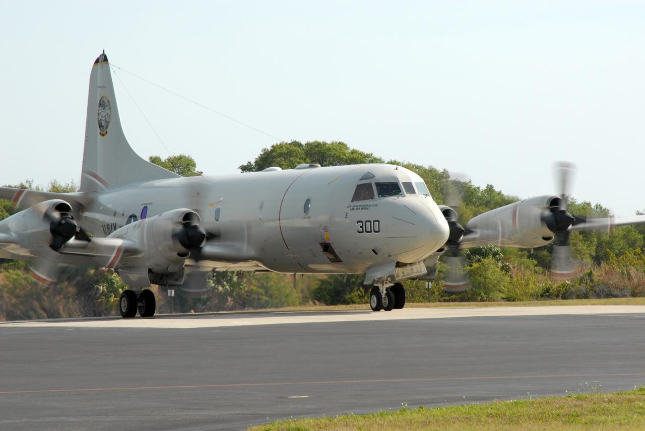
CAPE CANAVERAL, Fla. – The engines of U.S. Navy NP-3D Orion aircraft are started in preparation for takeoff from the Skid Strip at Cape Canaveral Air Force Station. The plane will fly below space shuttle Discovery as it approaches Kennedy Space Center for landing following the STS-119 mission. Onboard instruments will check the orbiter’s exterior temperatures and a long-range infrared camera will remotely monitor heating to the shuttle’s lower surface, part of the boundary layer transition flight experiment. For the experiment, a heat shield tile with a “speed bump” on it was installed under Discovery’s left wing to intentionally disturb the airflow in a controlled manner and make the airflow turbulent. The tile, a BRI-18, was originally developed as a potential heat shield upgrade on the orbiters and is being considered for use on the Constellation Program’s Orion crew exploration vehicles. The data will determine if a protuberance on a BRI-18 tile is safe to fly and will be used to verify and improve design efforts for future spacecraft. Photo credit: NASA/Jim Grossmann
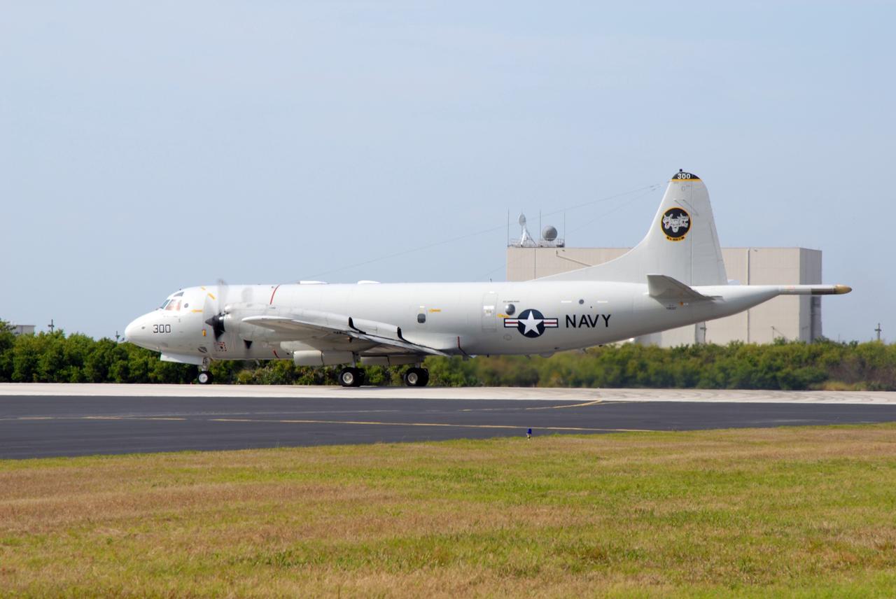
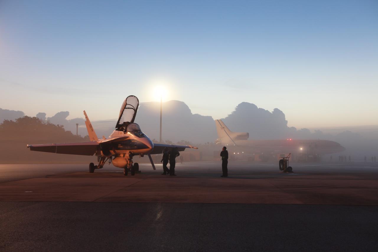
CAPE CANAVERAL, Fla. -- A U.S. Navy NP-3D Orion aircraft prepares for takeoff from the Skid Strip at Cape Canaveral Air Force Station. The plane will fly below space shuttle Discovery as it approaches Kennedy Space Center for landing following the STS-119 mission. Onboard instruments will check the orbiter’s exterior temperatures and a long-range infrared camera will remotely monitor heating to the shuttle’s lower surface, part of the boundary layer transition flight experiment. For the experiment, a heat shield tile with a “speed bump” on it was installed under Discovery’s left wing to intentionally disturb the airflow in a controlled manner and make the airflow turbulent. The tile, a BRI-18, was originally developed as a potential heat shield upgrade on the orbiters and is being considered for use on the Constellation Program’s Orion crew exploration vehicles. The data will determine if a protuberance on a BRI-18 tile is safe to fly and will be used to verify and improve design efforts for future spacecraft. Photo credit: NASA/Jim Grossmann
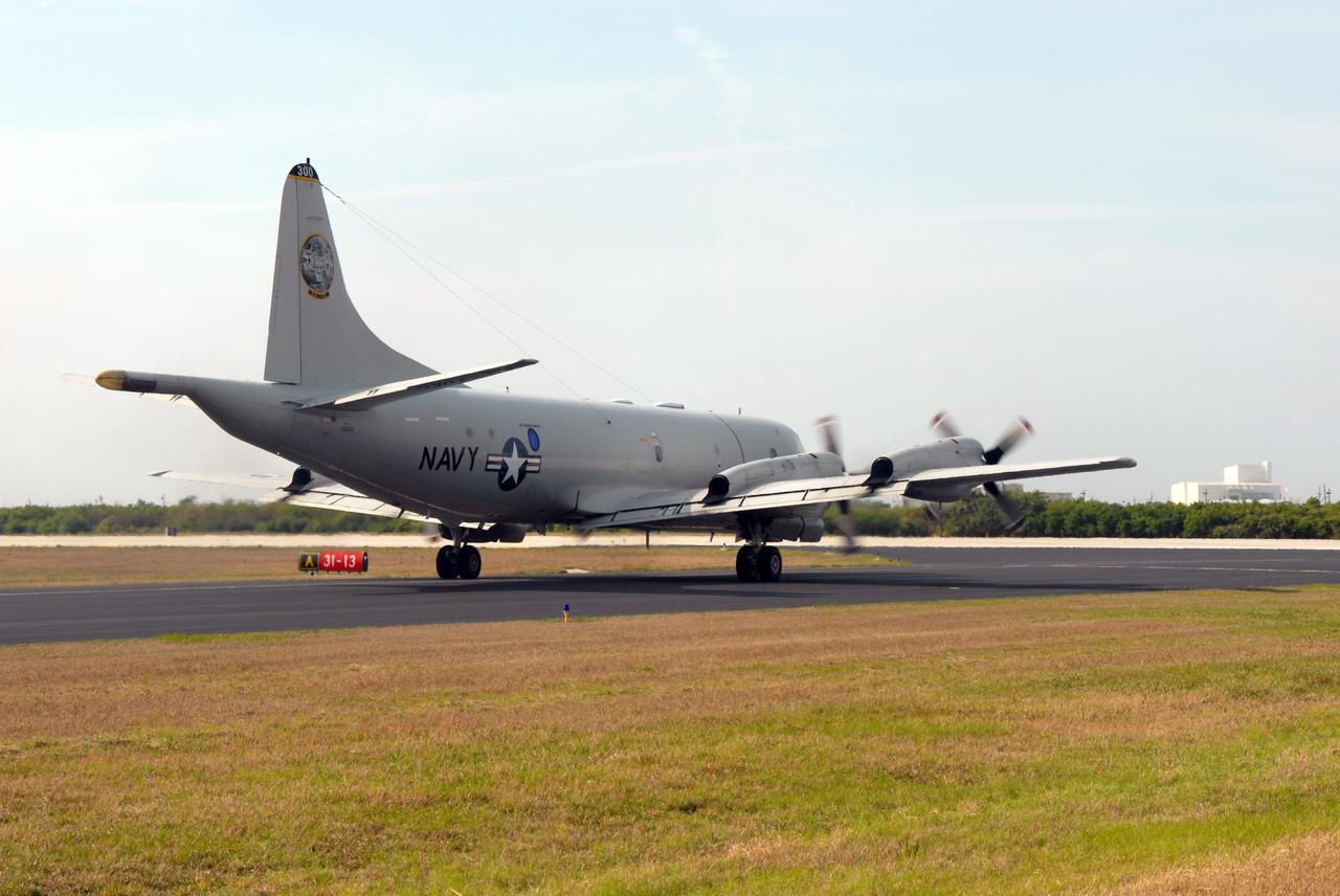
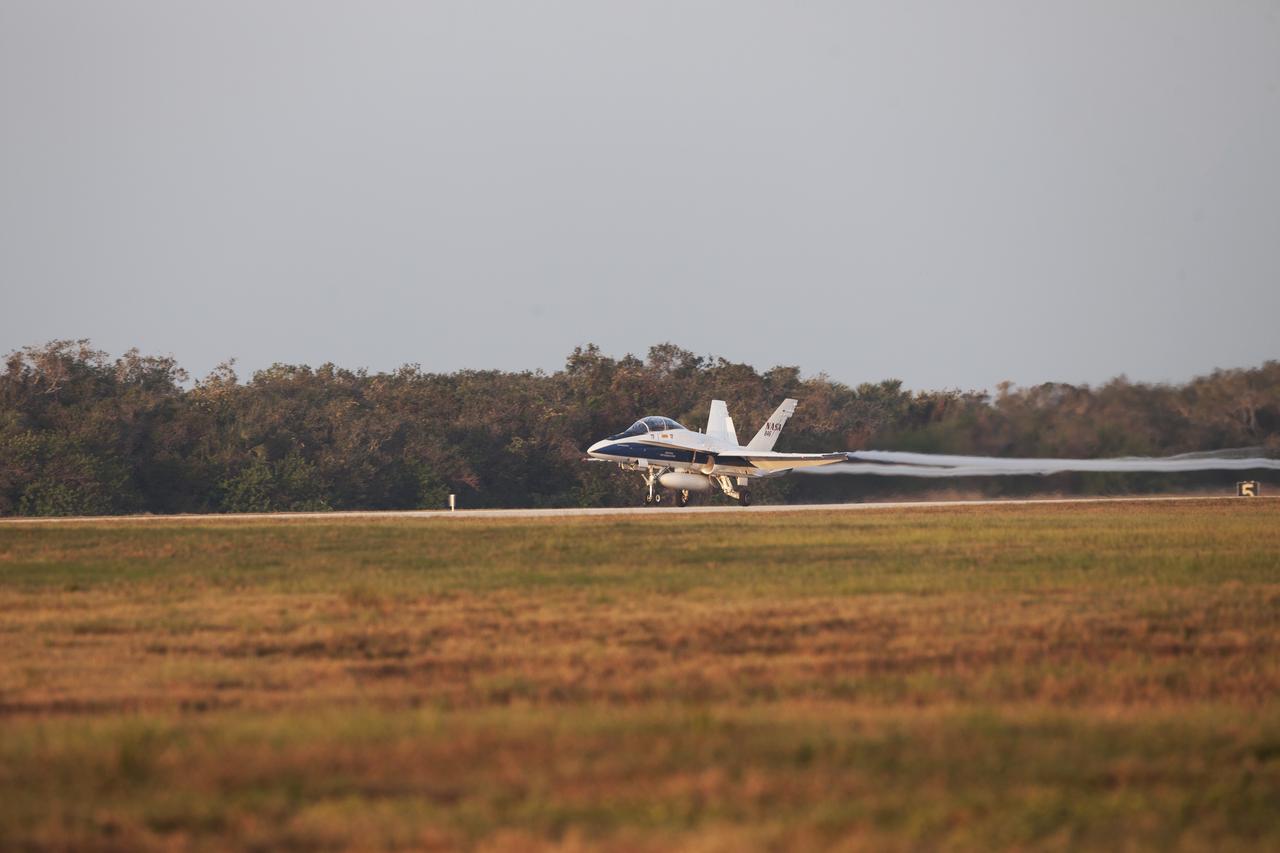
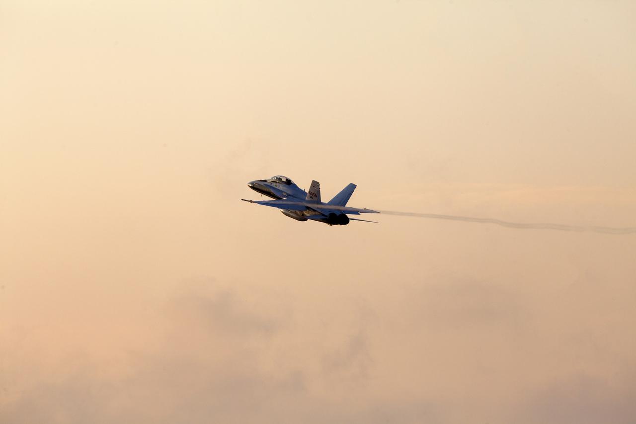
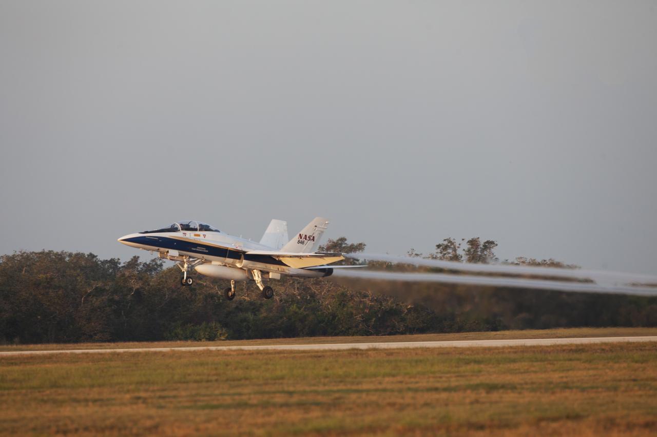
CAPE CANAVERAL, Fla. – A U.S. Navy NP-3D Orion aircraft takes off from the Skid Strip at Cape Canaveral Air Force Station. The plane will fly below space shuttle Discovery as it approaches Kennedy Space Center for landing following the STS-119 mission. Onboard instruments will check the orbiter’s exterior temperatures and a long-range infrared camera will remotely monitor heating to the shuttle’s lower surface, part of the boundary layer transition flight experiment. For the experiment, a heat shield tile with a “speed bump” on it was installed under Discovery’s left wing to intentionally disturb the airflow in a controlled manner and make the airflow turbulent. The tile, a BRI-18, was originally developed as a potential heat shield upgrade on the orbiters and is being considered for use on the Constellation Program’s Orion crew exploration vehicles. The data will determine if a protuberance on a BRI-18 tile is safe to fly and will be used to verify and improve design efforts for future spacecraft. Photo credit: NASA/Jim Grossmann
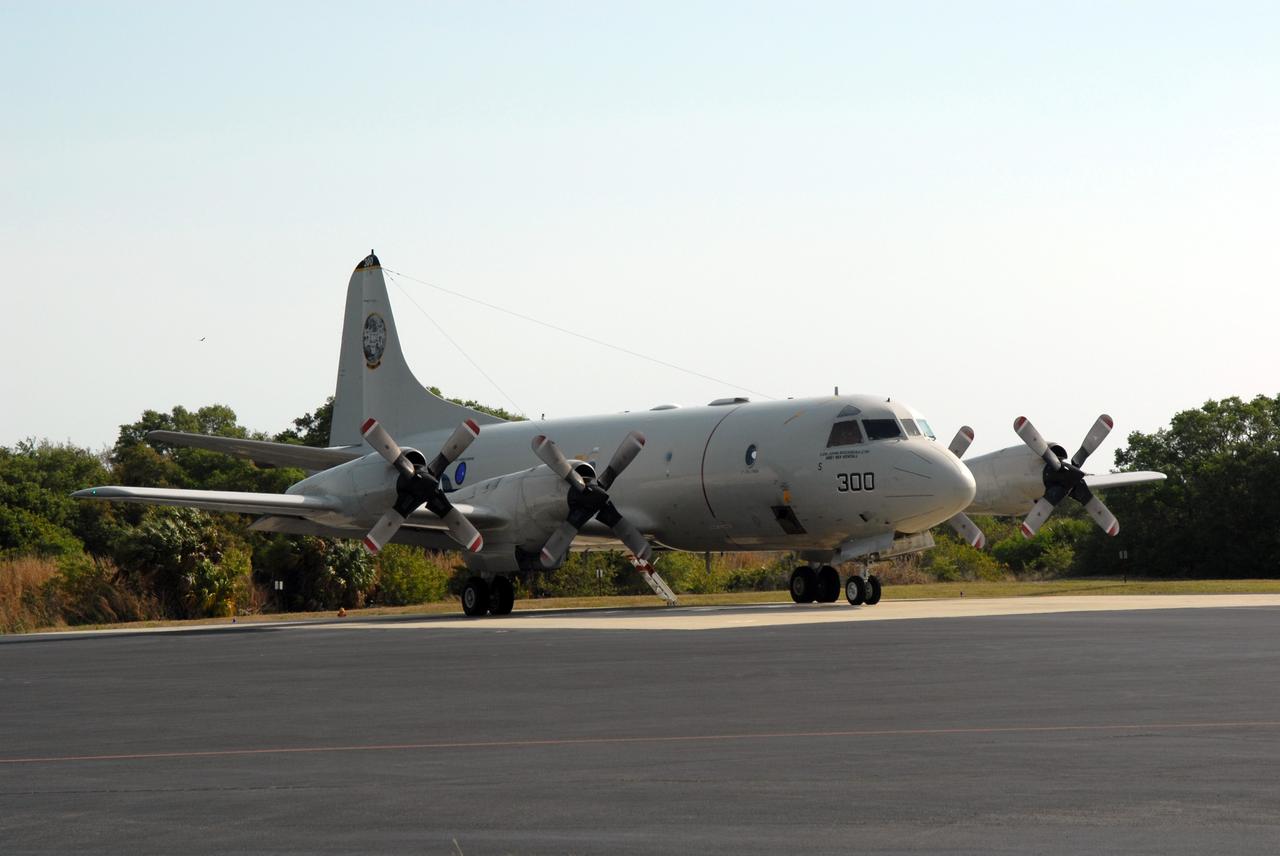
CAPE CANAVERAL, Fla. – A U.S. Navy NP-3D Orion aircraft taxies to the runway of the Skid Strip at Cape Canaveral Air Force Station in preparation for takeoff. The plane will fly below space shuttle Discovery as it approaches Kennedy Space Center for landing following the STS-119 mission. Onboard instruments will check the orbiter’s exterior temperatures and a long-range infrared camera will remotely monitor heating to the shuttle’s lower surface, part of the boundary layer transition flight experiment. For the experiment, a heat shield tile with a “speed bump” on it was installed under Discovery’s left wing to intentionally disturb the airflow in a controlled manner and make the airflow turbulent. The tile, a BRI-18, was originally developed as a potential heat shield upgrade on the orbiters and is being considered for use on the Constellation Program’s Orion crew exploration vehicles. The data will determine if a protuberance on a BRI-18 tile is safe to fly and will be used to verify and improve design efforts for future spacecraft. Photo credit: NASA/Jim Grossmann
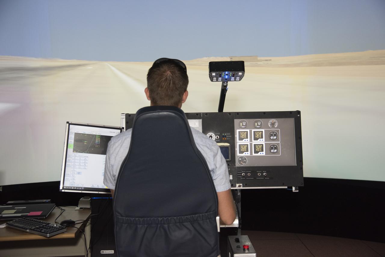
NASA's 2017 astronaut candidate Matthew Dominick practices flying in the X-57 aircraft simulator at Armstrong Flight Research Center in Southern California. Starting with the fuselage of a Tecnam P20067T, the X-57 Maxwell electric propulsion airplane is being built from ideas being researched that could lead to the development of electric propulsion-powered aircraft, which would be quieter, more efficient and environmentally friendly than today's commuter aircraft.
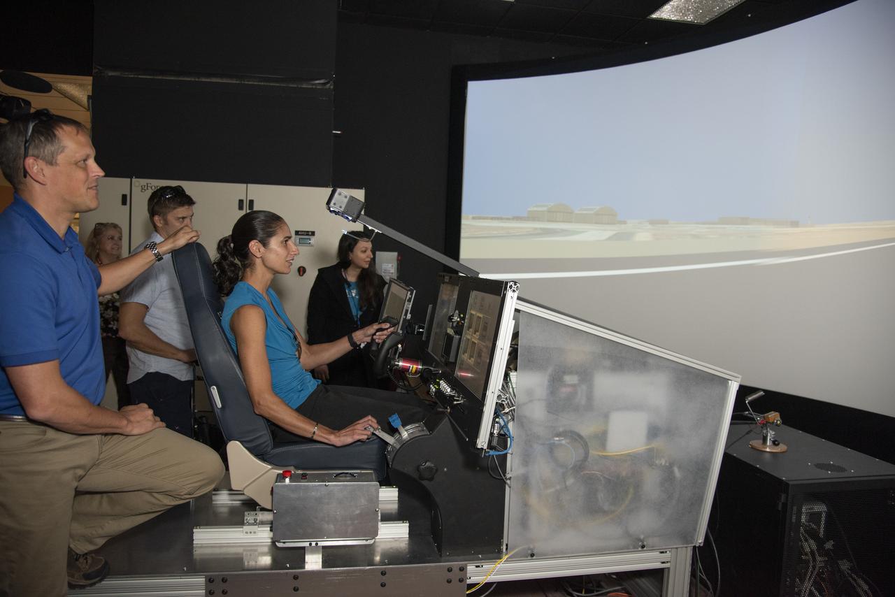
NASA's 2017 astronaut candidates (L to R) Bob Hines, Matthew Dominick and Jasmin Moghbeli practice flying in X-57 aircraft simulator at Armstrong Flight Research Center in Southern California. Starting with the fuselage of a Tecnam P20067T, the X-57 Maxwell electric propulsion airplane is being built from ideas being researched that could lead to the development of electric propulsion-powered aircraft, which would be quieter, more efficient and environmentally friendly than today's commuter aircraft.

Event: Horizontal Stabilator Install The Low Boom Flight Demonstrator manufacturing team installed the horizontal stabilizers to the aircraft. These are used along with the flight control computers to keep the airplane flying safely and providing the pitch control so that the pilot can fly the missions envisioned for the X-59
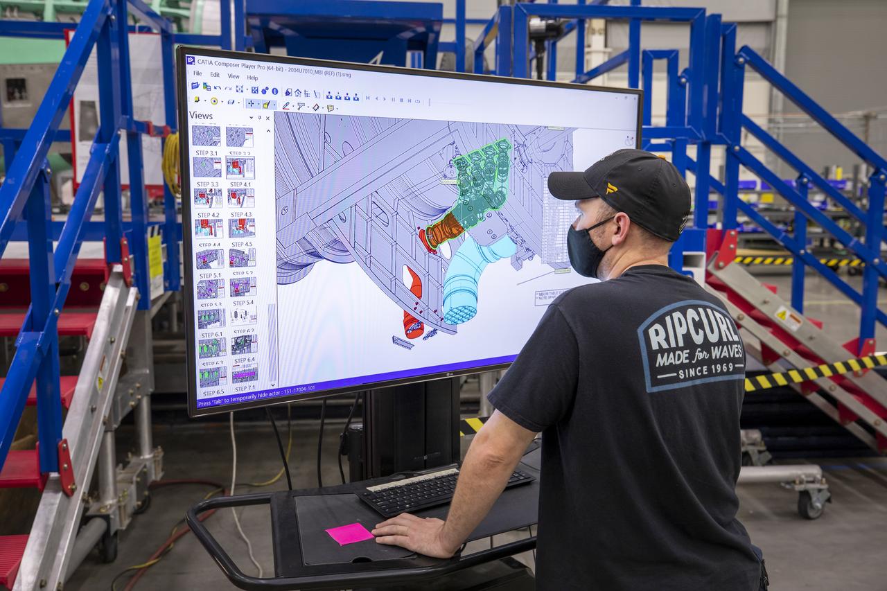
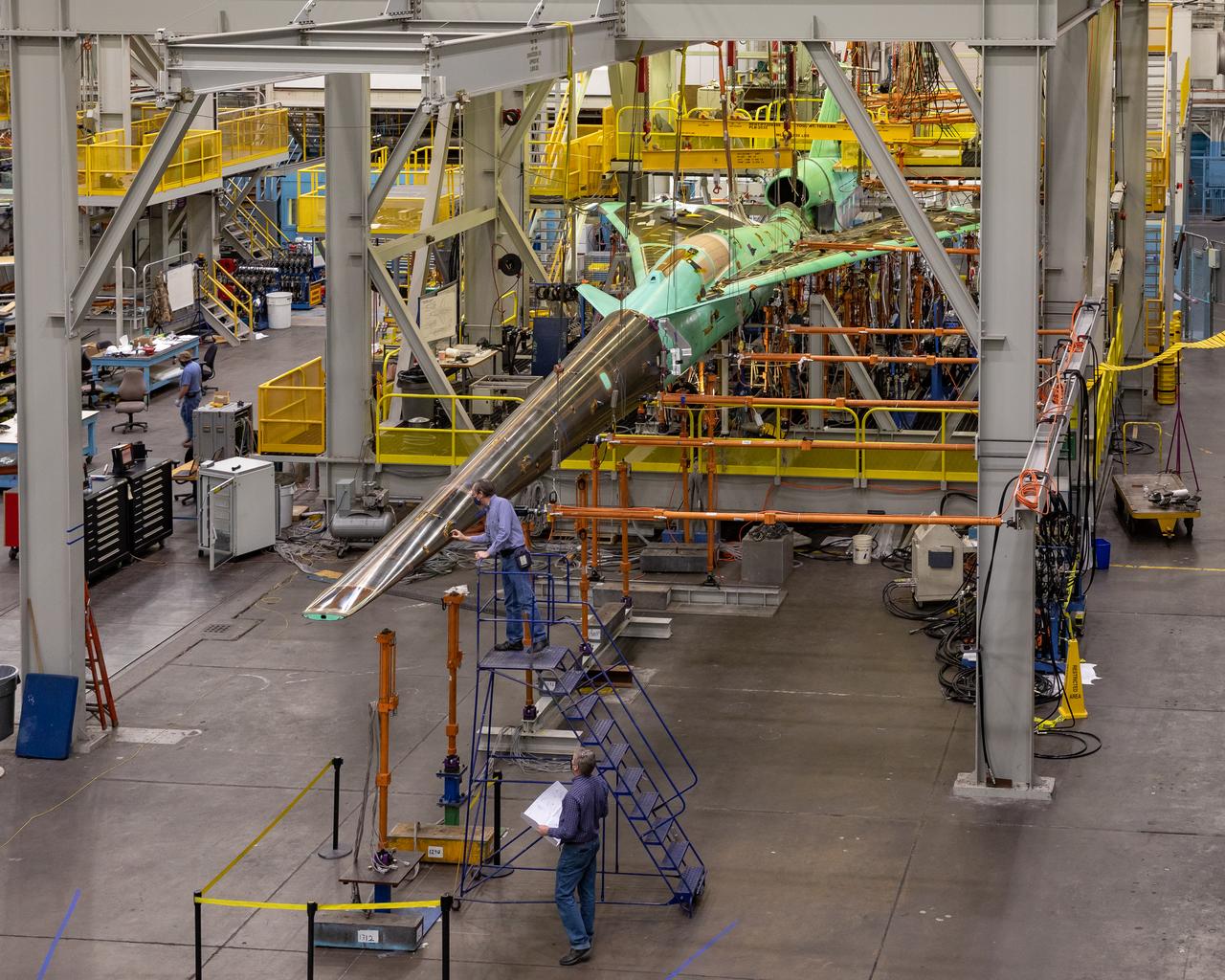
A Lockheed Martin technician looks at the connector installation on the cad model of the X-59 airplane. The aircraft, under construction at Lockheed Martin Skunk Works in Palmdale, California, will demonstrate the ability to fly supersonic while reducing the loud sonic boom to a quiet sonic thump.

Event: Horizontal Stabilator Install The Low Boom Flight Demonstrator manufacturing team installed the horizontal stabilizers to the aircraft. These are used along with the flight control computers to keep the airplane flying safely and providing the pitch control so that the pilot can fly the missions envisioned for the X-59.

Event: Horizontal Stabilator Install The Low Boom Flight Demonstrator manufacturing team installed the horizontal stabilizers to the aircraft. These are used along with the flight control computers to keep the airplane flying safely and providing the pitch control so that the pilot can fly the missions envisioned for the X-59.

Event: Horizontal Stabilator Install The Low Boom Flight Demonstrator manufacturing team installed the horizontal stabilizers to the aircraft. These are used along with the flight control computers to keep the airplane flying safely and providing the pitch control so that the pilot can fly the missions envisioned for the X-59.
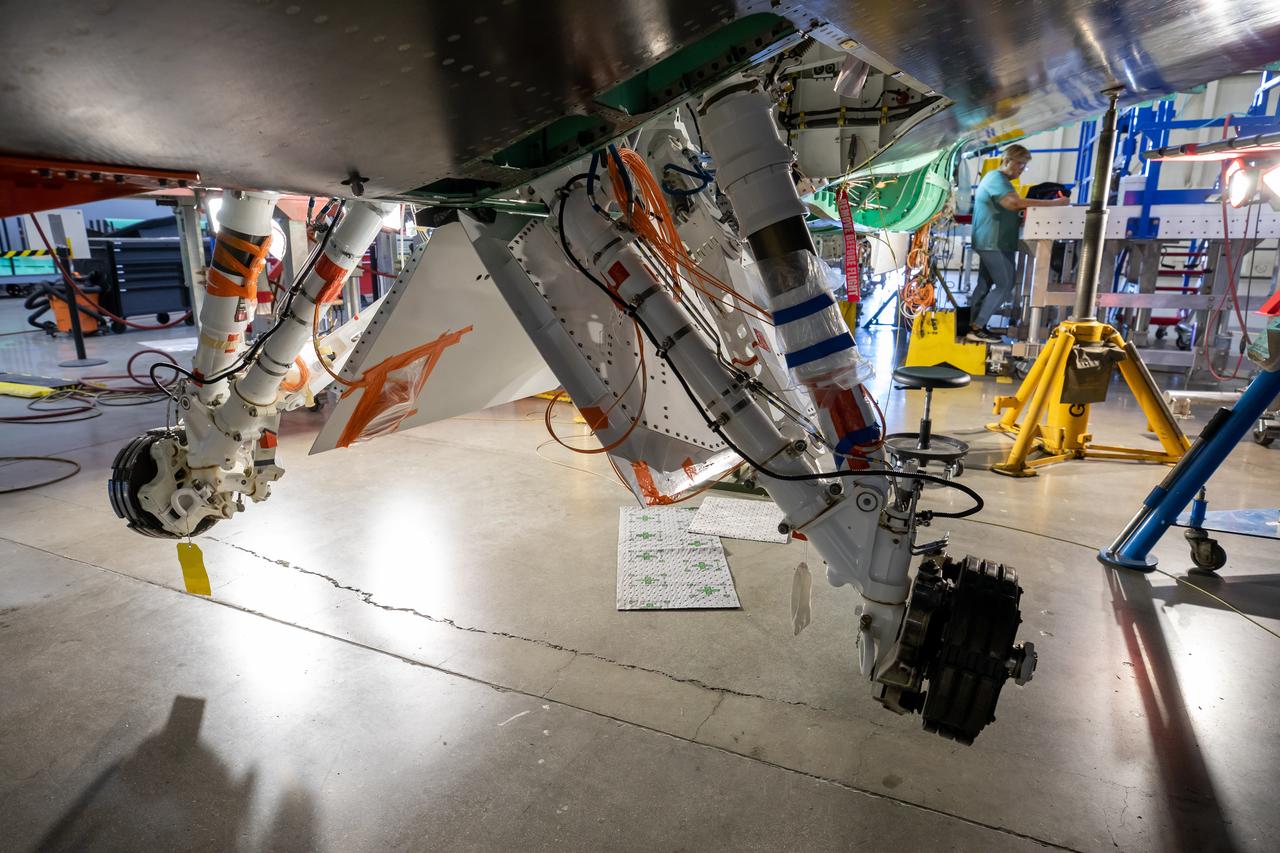
The Quesst team has repurposed the landing gear from an F-16 Fighting Falcon aircraft and is working on adjusting the fit onto the X-59 airplane. This is part of NASA’s Quesst mission which plans to help enable commercial supersonic air travel over land.
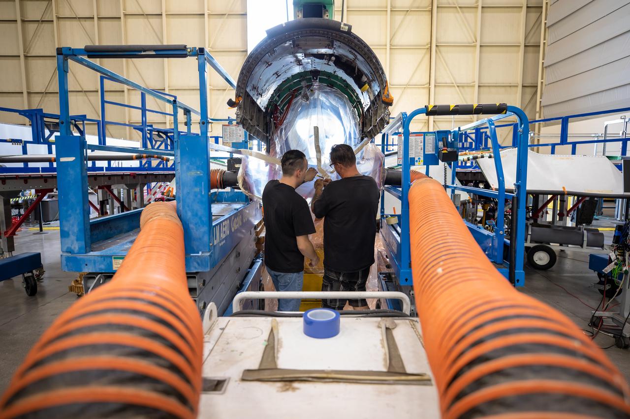
This image shows the extensive ventilation system that has been placed adjacent to the X-59 during the recent painting of the aircraft’s engine inlet. Once the aircraft build and ground testing are complete, the X-59 airplane will begin flight testing, working towards demonstrating the ability to fly supersonic while reducing the loud sonic boom to a quiet sonic thump and help enable commercial supersonic air travel over land.
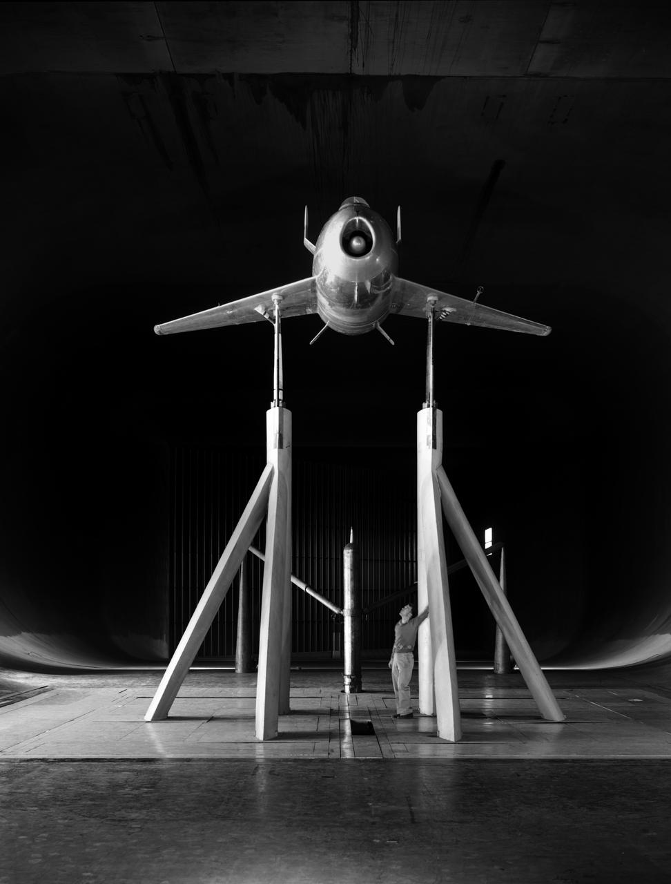
Front View of McDonald XP-85 Plan Model. Parasite Airplane designed to be carried in the B-36 bombay (never built) At the time it was the smallest Jet powered airplane. The McDonnell XF-85 Goblin was an American prototype fighter aircraft conceived during World War II by McDonnell Aircraft. It was intended to be deployed from the bomb bay of the giant Convair B-36 bomber as a parasite fighter. The XF-85's intended role was to defend bombers from hostile interceptor aircraft, a need demonstrated during World War II
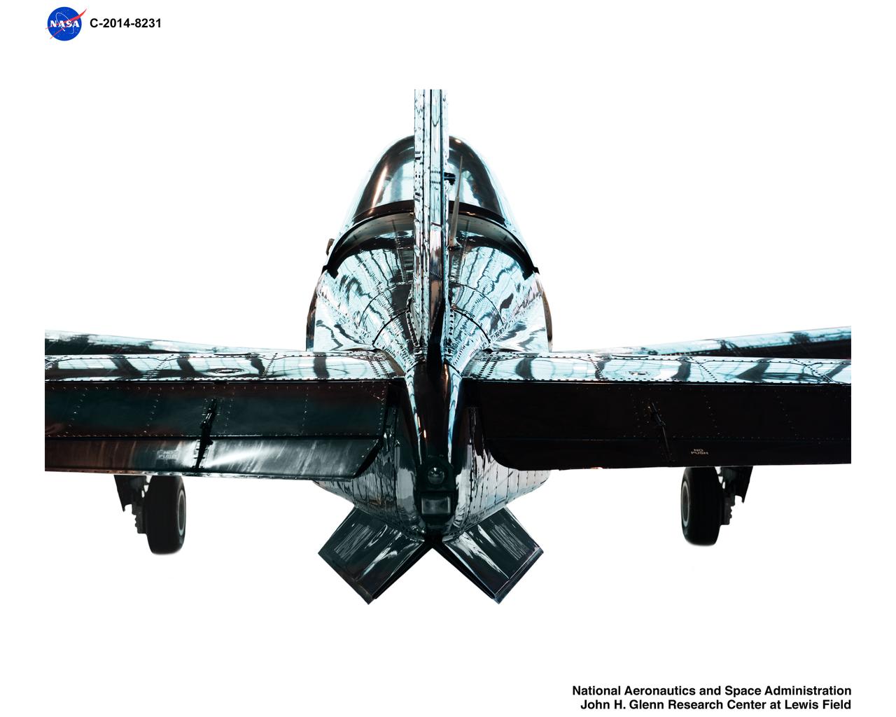
A T34-C aircraft reflects the large multi-paned windows on the Hangar doors. When NASA GRC obtained this T-34C from the Navy it was painted in ‚Äúthrowback‚Äù paint schemes from an earlier time in celebration of the 100th birthday of Naval Aviation. NASA kept it in the original paint job for posterity. This T-34C airplane will be GRCs surrogate aircraft for Unmanned Aircraft Systems in the National Airspace System aeronautics initiative. A T34-C aircraft reflects the large multi-paned windows on the Hangar doors. When NASA GRC obtained this T-34C from the Navy it was painted in “throwback” paint schemes from an earlier time in celebration of the 100th birthday of Naval Aviation. NASA kept it in the original paint job for posterity. This T-34C airplane will be GRCs surrogate aircraft for Unmanned Aircraft Systems in the National Airspace System aeronautics initiative.
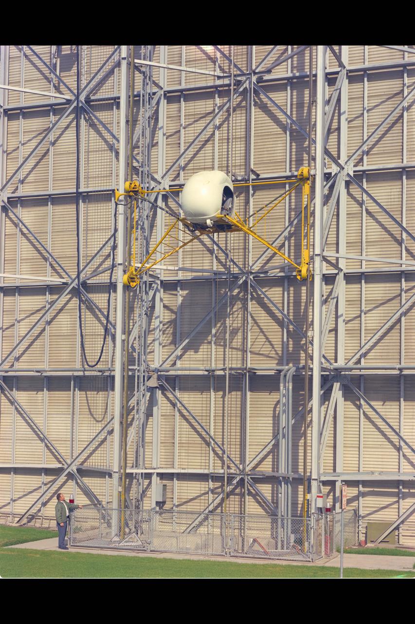
Height-Control Test Apparatus (HICONTA) Simulator mounted to the exterior of the 40x80ft W.T. Building N-221B and provided extensive vertical motion simulating airplanes, helicopter and V/STOL aircraft
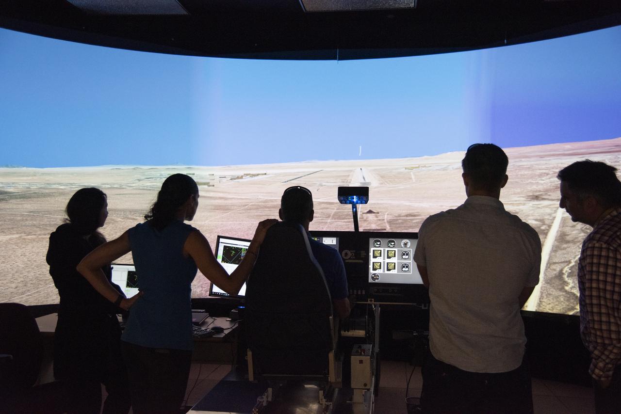
NASA's 2017 astronaut candidates toured aircraft hangar at Armstrong Flight Research Center, in Southern California. After tour of aircraft hangar and briefing on the use of aircraft for flight research, the astronauts practiced flying the X-57 simulator. Starting with the fuselage of a Tecnam P20067T, the X-57 Maxwell electric propulsion airplane is being built and could lead to the development of electric propulsion-powered aircraft, which would be quieter, more efficient and environmentally friendly than today's commuter aircraft.
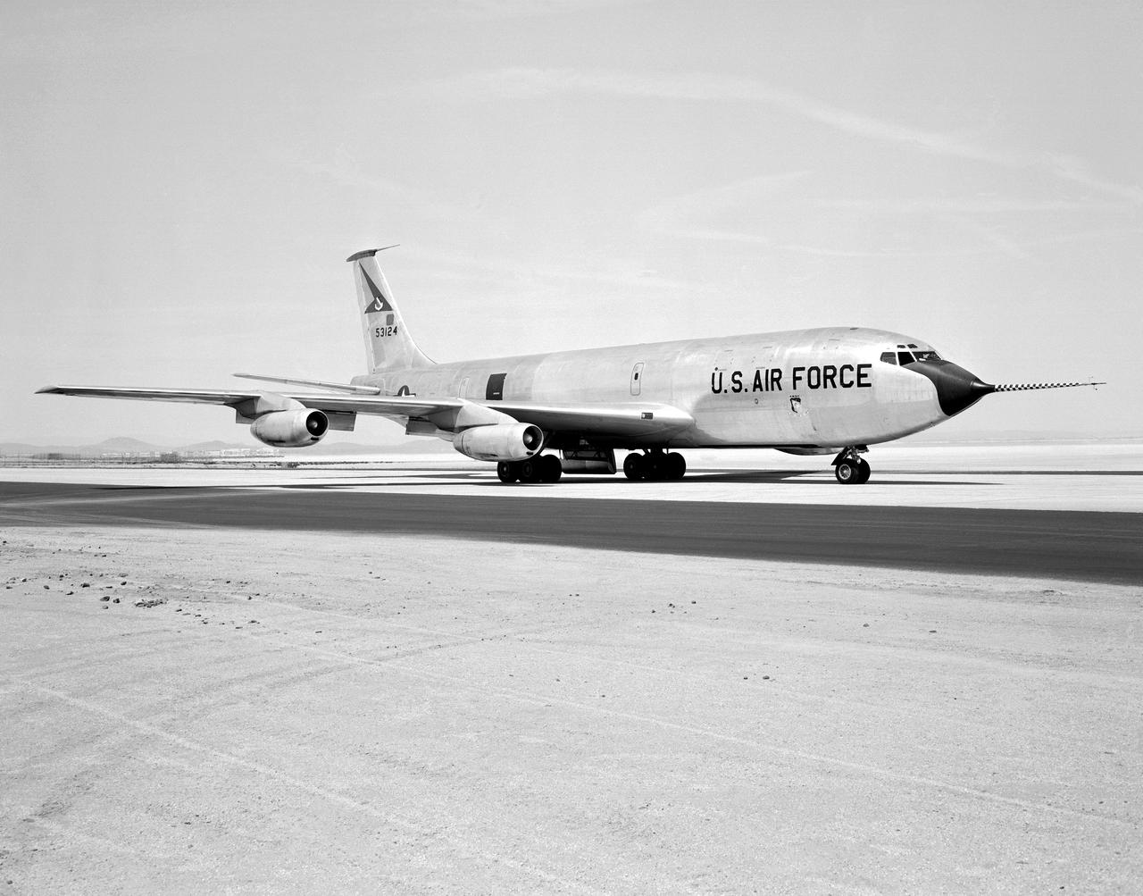
The Boeing KC-135 Stratotanker, besides being used extensively in its primary role as an inflight aircraft refueler, has assisted in several projects at the NASA Dryden Flight Research Center, Edwards, California. In 1957 and 1958, Dryden was asked by what was then the Civil Aeronautics Administration (later absorbed into the Federal Aviation Administration (FAA) in 1958) to help establish new approach procedure guidelines on cloud-ceiling and visibility minimums for Boeing's first jet airliner, the B-707. Dryden used a KC-135 (the military variant of the 707), seen here on the runway at Edwards Air Force Base, to aid the CAA in these tests. In 1979 and 1980, Dryden was again involved with general aviation research with the KC-135. This time, a special wingtip "winglet", developed by Richard Whitcomb of Langley Research Center, was tested on the jet aircraft. Winglets are small, nearly vertical fins installed on an airplane's wing tips to help produce a forward thrust in the vortices that typically swirl off the end of the wing, thereby reducing drag. This winglet idea was tested at the Dryden Flight Research Center on a KC-135A tanker loaned to NASA by the Air Force. The research showed that the winglets could increase an aircraft's range by as much as 7 percent at cruise speeds. The first application of NASA's winglet technology in industry was in general aviation business jets, but winglets are now being incorporated into most new commercial and military transport jets, including the Gulfstream III and IV business jets, the Boeing 747-400 and MD-11 airliners, and the C-17 military transport. In the 1980's, a KC-135 was used in support of the Space Shuttle program. Since the Shuttle was to be launched from Florida, researchers wanted to test the effect of rain on the sensitive thermal tiles. Tiles were mounted on special fixtures on an F-104 aircraft and a P-3 Orion. The F-104 was flown in actual rain conditions, and also behind the KC-135 spray tanker as it rel
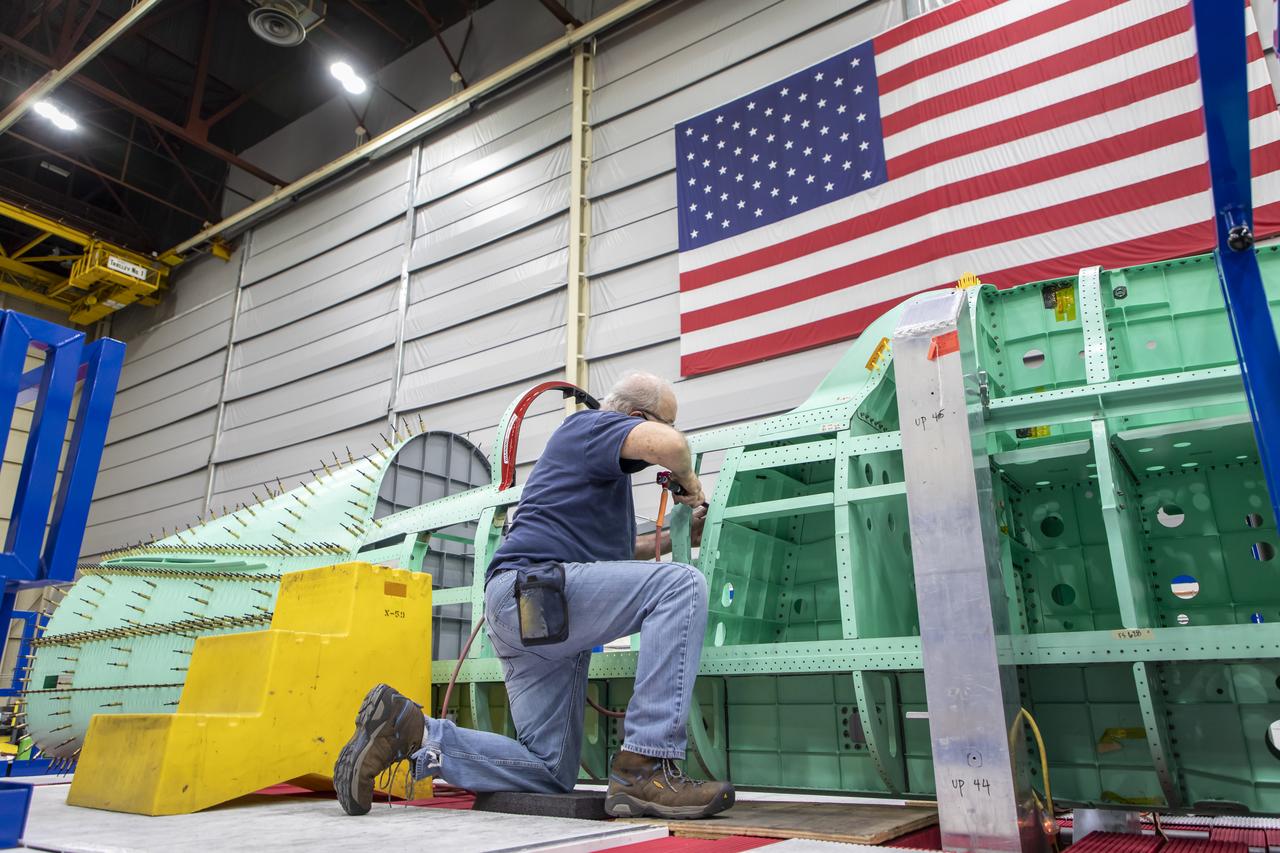
Event: SEG 210 Forebody A Lockheed Martin technician works on the ejection seat support structure and once complete, the ejection seat rails will be installed on the X-59 airplane. The aircraft, under construction at Lockheed Martin Skunk Works in Palmdale, California, will demonstrate the ability to fly supersonic while reducing the loud sonic boom to a quiet sonic thump.
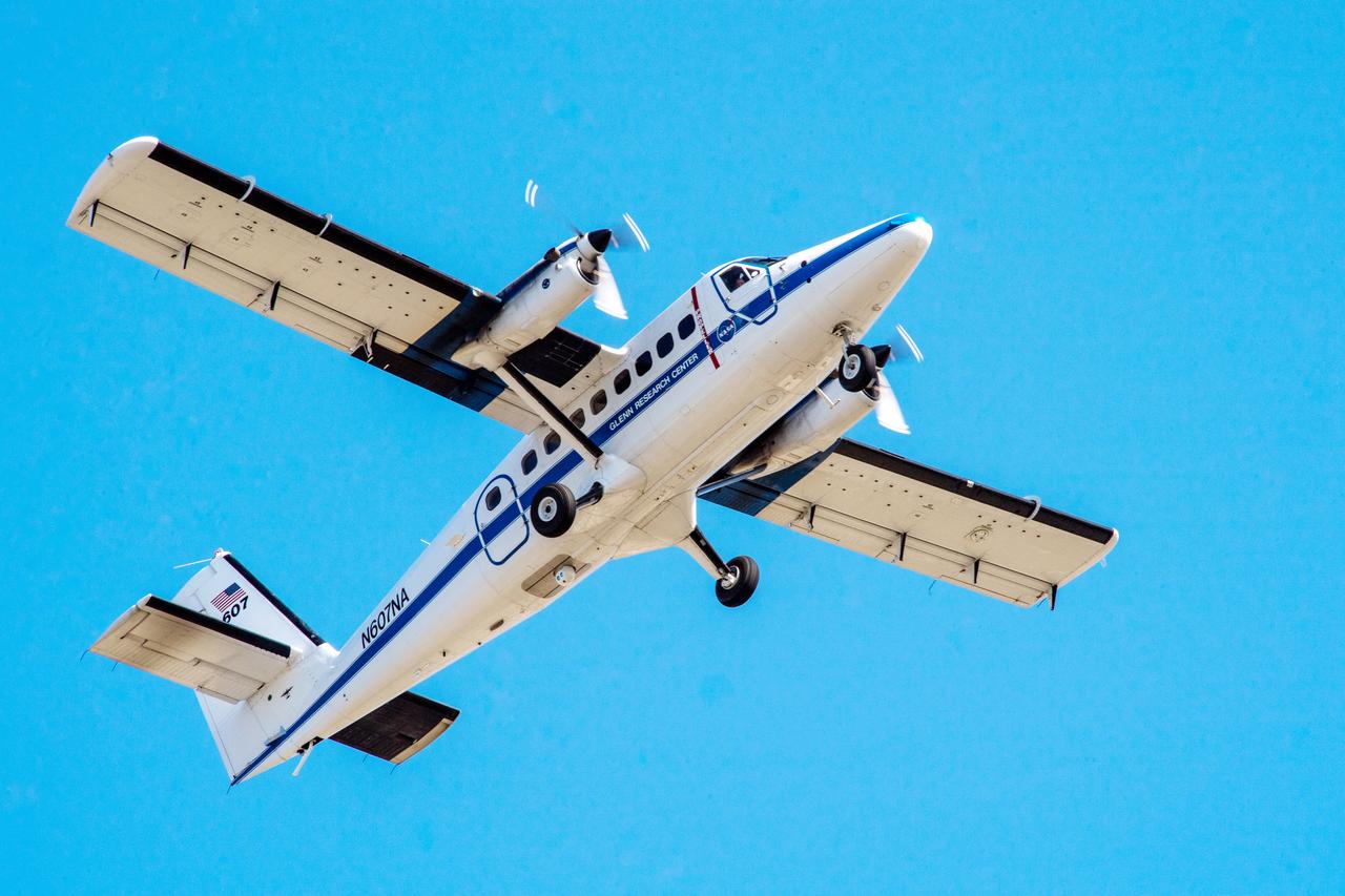
Twin Otter Aircraft, N607NA
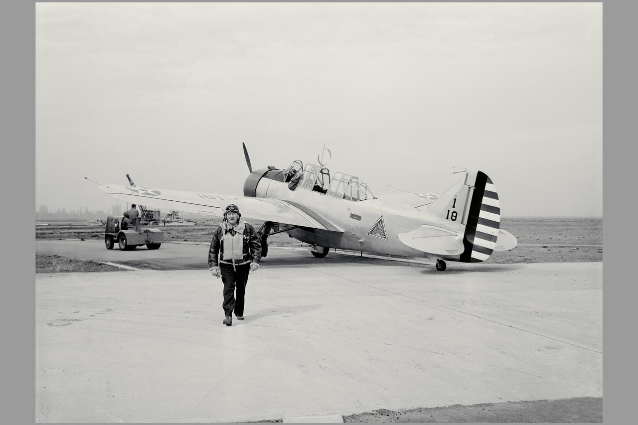
A new three-place North American O-47A observation airplane with Army Air Corps marking was the first ircraft to arrive at Ames. The Circular antenna on top of the canopy is for direction finding. A close look show that help from the front cockpit was needed for directional control when using a rope (instead of a tow bar) to tow the aircraft. (Sept 1940). W.H. McAvoy Ames test pilot returning from an early flight of first test airplane at Ames, a North American O-47A-1 (or 0-47 AAC37-323) This aircraft severed for a short time upon arrival as a research aircraft for heated-wing deicing. NOTE: printed in NASA Ames Publications: Adventures in Research - SP-4320 57 Years - Flight Research at AMES - NASA SP-1998-3300
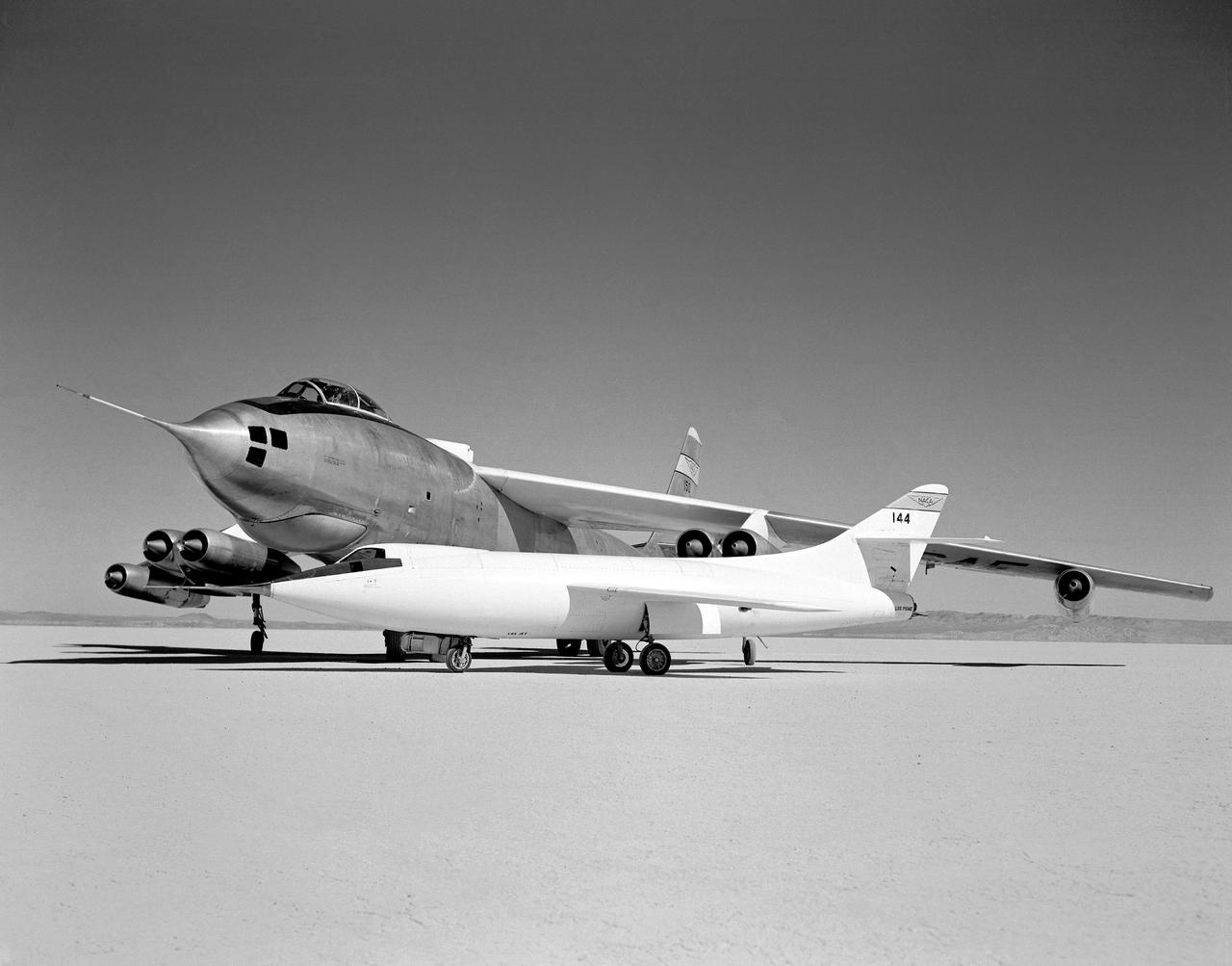
In 1954 this photo of two swept wing airplanes was taken on the ramp of NACA High-Speed Flight Research Station. The Douglas D-558-ll is a research aircraft while the Boeing B-47A Stratojet is a production bomber and very different in size. Both contributed to the studies for swept back wing research.
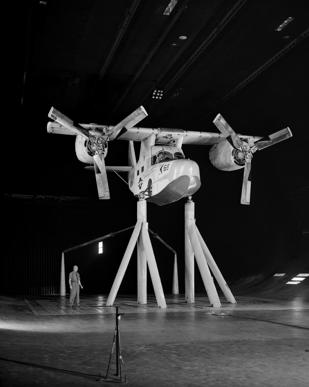
Test No. 175 Kaman K-16 in 40x80 Foot Wind Tunnel at Ames Research Center. Pictured with two Kaman employees. 3/4 Front view of Airplane. Kaman K-16B was an experimental tilt wing aircraft, it used the fuselage of a JRF-5 and was powered by two General Electric YT58-GE-2A engines.
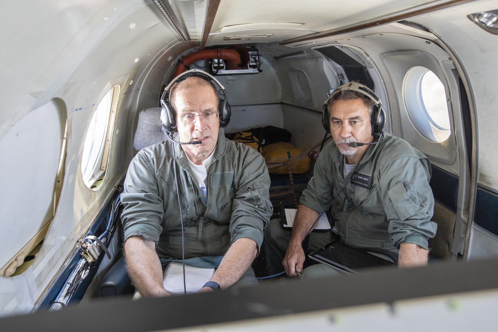
Aerospace Engineers, “from left to right” Peter Coen and Randy Bailey attempt to spot an incoming aircraft on the monitor while performing tests on the External Vision System (XVS) Software. The software testing is being conducted on the B200 King Air Beechcraft airplane.
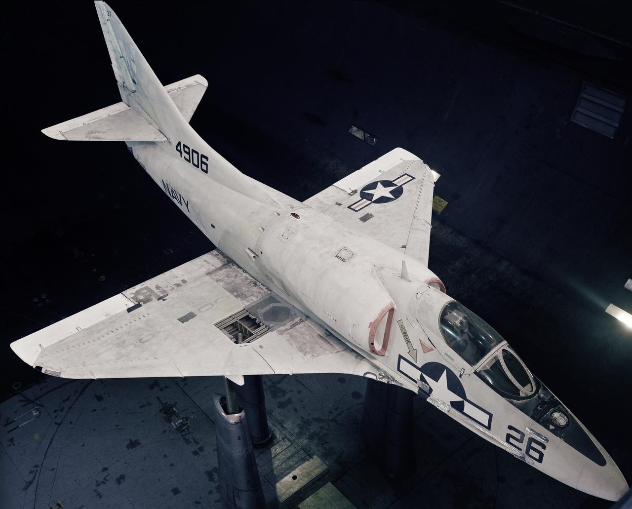
Battle Damage test conducted in the Ames 40x80ft. Subsonic Wind Tunnel, Ames Research Center Moffett Field, CA on the Navy A-4B airplane (The delta winged, single-engined Skyhawk was designed and produced by Douglas Aircraft Company model I.d. Numbers 4906 and 3A244)
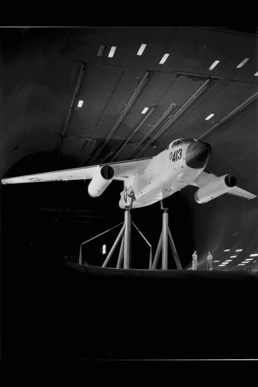
DOUGLAS XA3D-1 #413 AIRPLANE MOUNTED IN THE NACA AMES RESEARCH CENTER'S 40X80_FOOT SUBSONIC WIND TUNNEL sweptback wing Testing the wing boundary layer control of the A3D in the 40 x 80 wind tunnel. Boundary layer control was added to increase the lift of the wing for aircraft carrier take off and landing.
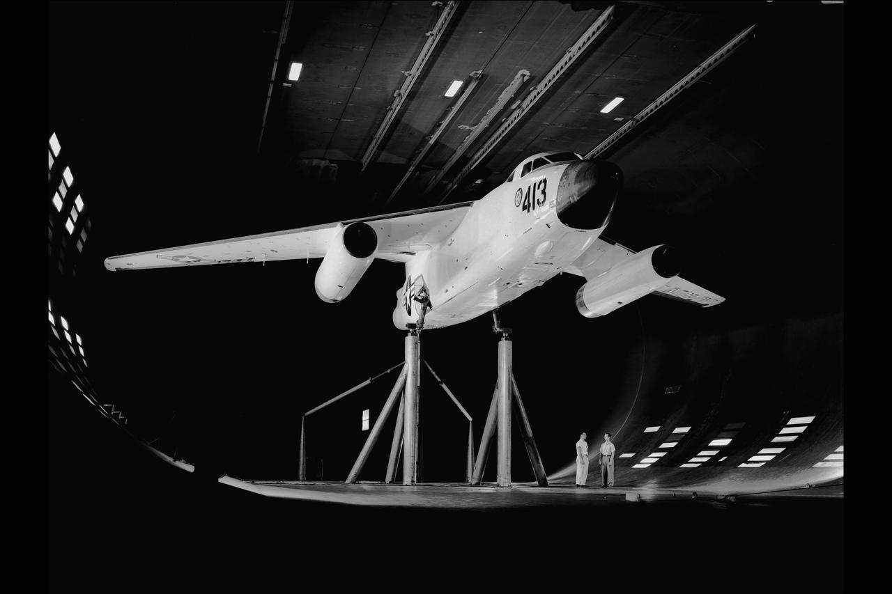
DOUGLAS XA3D-1 #413 AIRPLANE MOUNTED IN THE NACA AMES RESEARCH CENTER'S 40X80_FOOT SUBSONIC WIND TUNNEL Testing the boundary layer control of the A3D in the 40 x 80 wind tunnel. Boundary layer control was added to increase the lift of the wing for take off from an aircraft carrier.
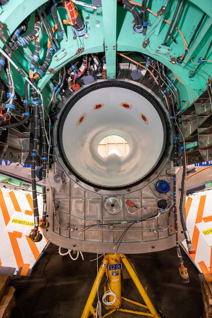
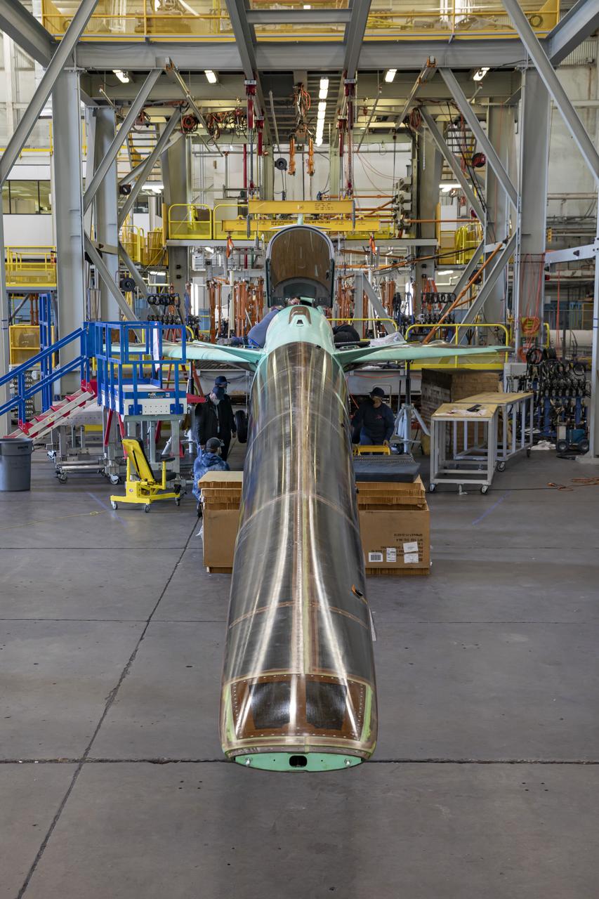
This image shows the X-59’s engine inlet from the aft view, which is the rear of the airplane, looking forward. Once the aircraft and ground testing are complete, the X-59 will undergo flight testing, which will demonstrate the plane’s ability to fly supersonic - faster than the speed of sound - while reducing the loud sonic boom. This could enable commercial supersonic air travel over land again.
NASA’s X-59 undergoes a structural stress test at Lockheed Martin’s facility in Fort Worth, Texas. The X-59’s nose makes up one third of the aircraft, at 38-feet in length. The X-59 is a one-of-a-kind airplane designed to fly at supersonic speeds without making a startling sonic boom sound for the communities below. This is part of NASA’s Quesst mission, which plans to help enable supersonic air travel over land
NASA’s X-59 undergoes a structural stress test at a Lockheed Martin facility in Fort Worth, Texas. The X-59’s nose makes up one third of the aircraft, at 38-feet in length. The X-59 is a one-of-a-kind airplane designed to fly at supersonic speeds without making aa startling sonic boom sound for the communities below. This is part of NASA’s Quesst mission which plans to help enable supersonic air travel over land
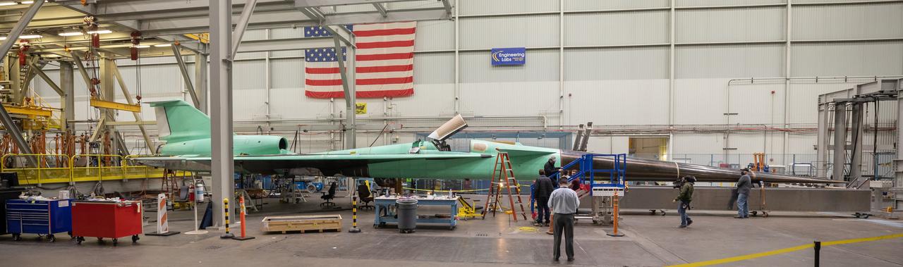
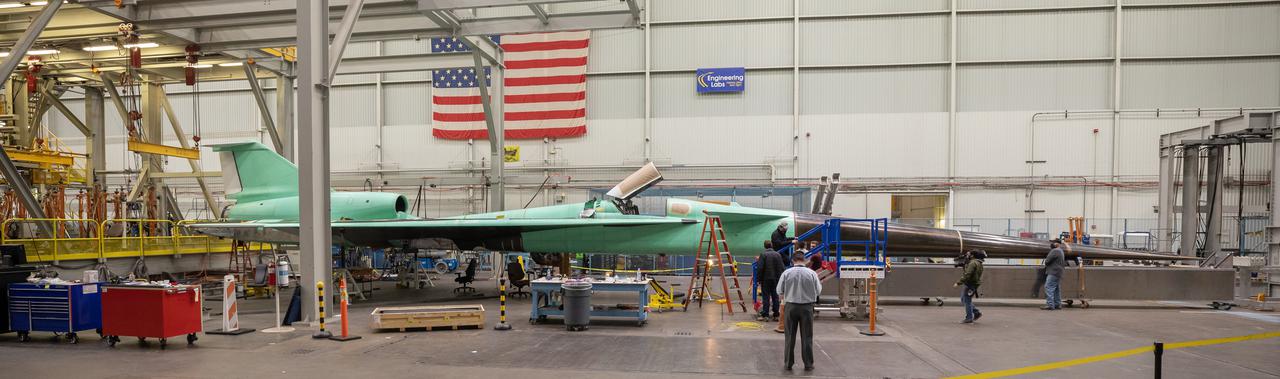
A panoramic view of NASA’s X-59 in Fort Worth, Texas to undergo structural and fuel testing. The X-59’s nose makes up one third of the aircraft, at 38-feet in length. The X-59 is a one-of-a-kind airplane designed to fly at supersonic speeds without making a startling sonic boom sound for the communities below. This is part of NASA’s Quesst mission which plans to help enable supersonic air travel over land.

This overview shot of the X-59 Quiet Supersonic Technology or QueSST aircraft shows the vehicle before a major merger of three major aircraft sections – the fuselage, the wing, and the tail assembly – together, making it looks more like an airplane. Lockheed Martin Photography By Garry Tice 1011 Lockheed Way, Palmdale, Ca. 93599 Event: Manufacture Area From Above Date: 3/30/2021
A pathfinder aircraft descends for touchdown at the Skid Strip at Cape Canaveral Air Force Station in Florida. The airplane provided photographic and video imagery of the Orbital ATK L-1011 Stargazer aircraft carrying a Pegasus XL Rocket with eight NASA Cyclone Global Navigation Satellite System, or CYGNSS, spacecraft. With the aircraft flying off shore, the Pegasus rocket was released at 8:37 a.m. EST. Five seconds later, the solid propellant engine ignited and boosted the eight hurricane observatories to orbit. The eight CYGNSS satellites will make frequent and accurate measurements of ocean surface winds throughout the life cycle of tropical storms and hurricanes.
A pathfinder aircraft begins its takeoff from the Skid Strip at Cape Canaveral Air Force Station in Florida. The airplane will provide photographic and video imagery of the Orbital ATK L-1011 Stargazer aircraft carrying a Pegasus XL Rocket with eight NASA Cyclone Global Navigation Satellite System, or CYGNSS, spacecraft. With the aircraft flying off shore, the Pegasus rocket will be released. Five seconds later, the solid propellant engine will ignite and boost the eight hurricane observatories to orbit. The eight CYGNSS satellites will make frequent and accurate measurements of ocean surface winds throughout the life cycle of tropical storms and hurricanes.
A pathfinder aircraft soars high after takeoff from the Skid Strip at Cape Canaveral Air Force Station in Florida. The airplane will provide photographic and video imagery of the Orbital ATK L-1011 Stargazer aircraft carrying a Pegasus XL Rocket with eight NASA Cyclone Global Navigation Satellite System, or CYGNSS, spacecraft. With the aircraft flying off shore, the Pegasus rocket will be released. Five seconds later, the solid propellant engine will ignite and boost the eight hurricane observatories to orbit. The eight CYGNSS satellites will make frequent and accurate measurements of ocean surface winds throughout the life cycle of tropical storms and hurricanes.
A pathfinder aircraft takes off from the Skid Strip at Cape Canaveral Air Force Station in Florida. The airplane will provide photographic and video imagery of the Orbital ATK L-1011 Stargazer aircraft carrying a Pegasus XL Rocket with eight NASA Cyclone Global Navigation Satellite System, or CYGNSS, spacecraft. With the aircraft flying off shore, the Pegasus rocket will be released. Five seconds later, the solid propellant engine will ignite and boost the eight hurricane observatories to orbit. The eight CYGNSS satellites will make frequent and accurate measurements of ocean surface winds throughout the life cycle of tropical storms and hurricanes.
A pathfinder aircraft prepares for takeoff from the Skid Strip at Cape Canaveral Air Force Station in Florida. The airplane will provide photographic and video imagery of the Orbital ATK L-1011 Stargazer aircraft carrying a Pegasus XL Rocket with eight NASA Cyclone Global Navigation Satellite System, or CYGNSS, spacecraft. With the aircraft flying off shore, the Pegasus rocket will be released. Five seconds later, the solid propellant engine will ignite and boost the eight hurricane observatories to orbit. The eight CYGNSS satellites will make frequent and accurate measurements of ocean surface winds throughout the life cycle of tropical storms and hurricanes.
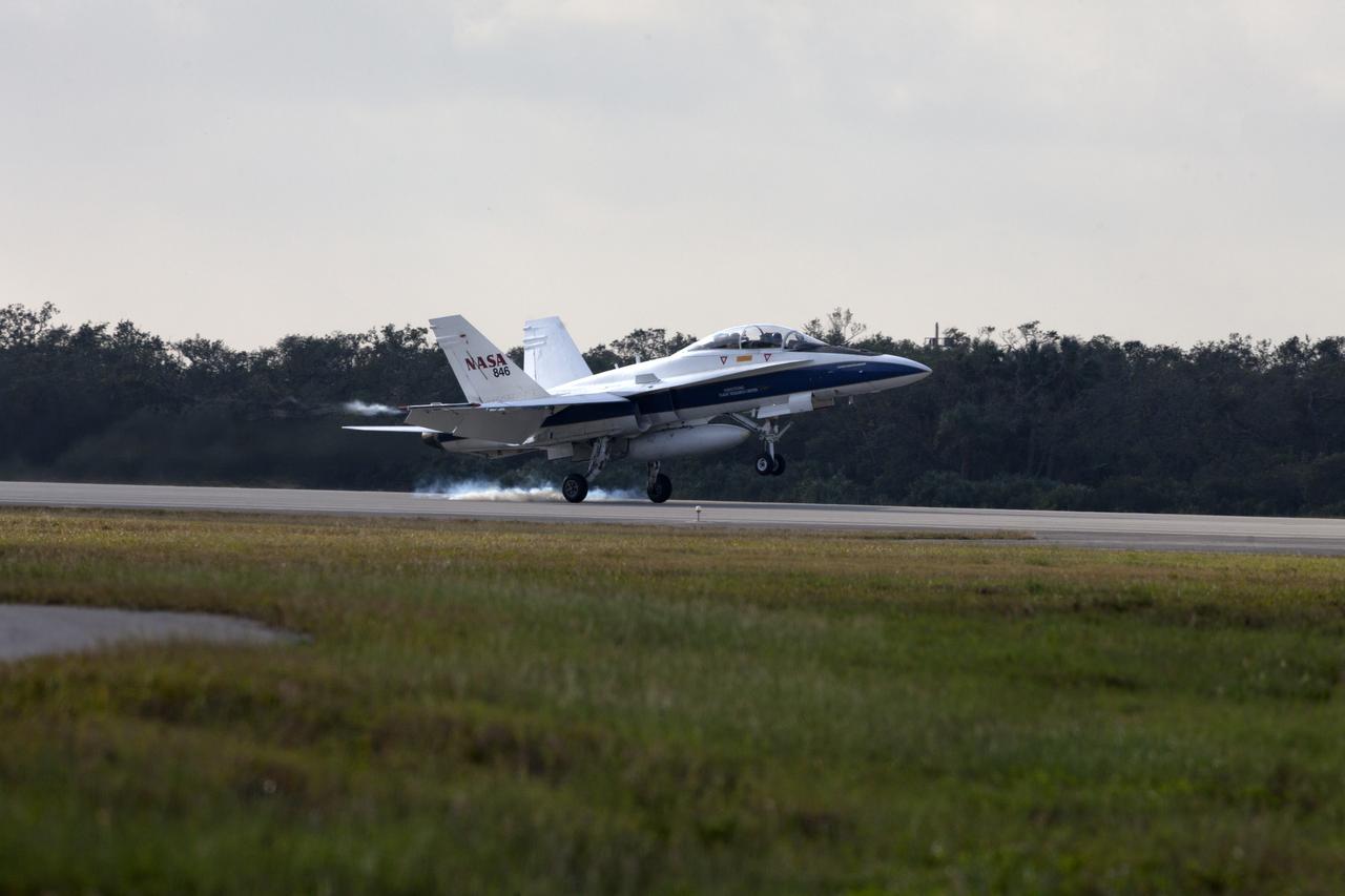
A pathfinder aircraft touches down at the Skid Strip at Cape Canaveral Air Force Station in Florida. The airplane provided photographic and video imagery of the Orbital ATK L-1011 Stargazer aircraft carrying a Pegasus XL Rocket with eight NASA Cyclone Global Navigation Satellite System, or CYGNSS, spacecraft. With the aircraft flying off shore, the Pegasus rocket was released at 8:37 a.m. EST. Five seconds later, the solid propellant engine ignited and boosted the eight hurricane observatories to orbit. The eight CYGNSS satellites will make frequent and accurate measurements of ocean surface winds throughout the life cycle of tropical storms and hurricanes.
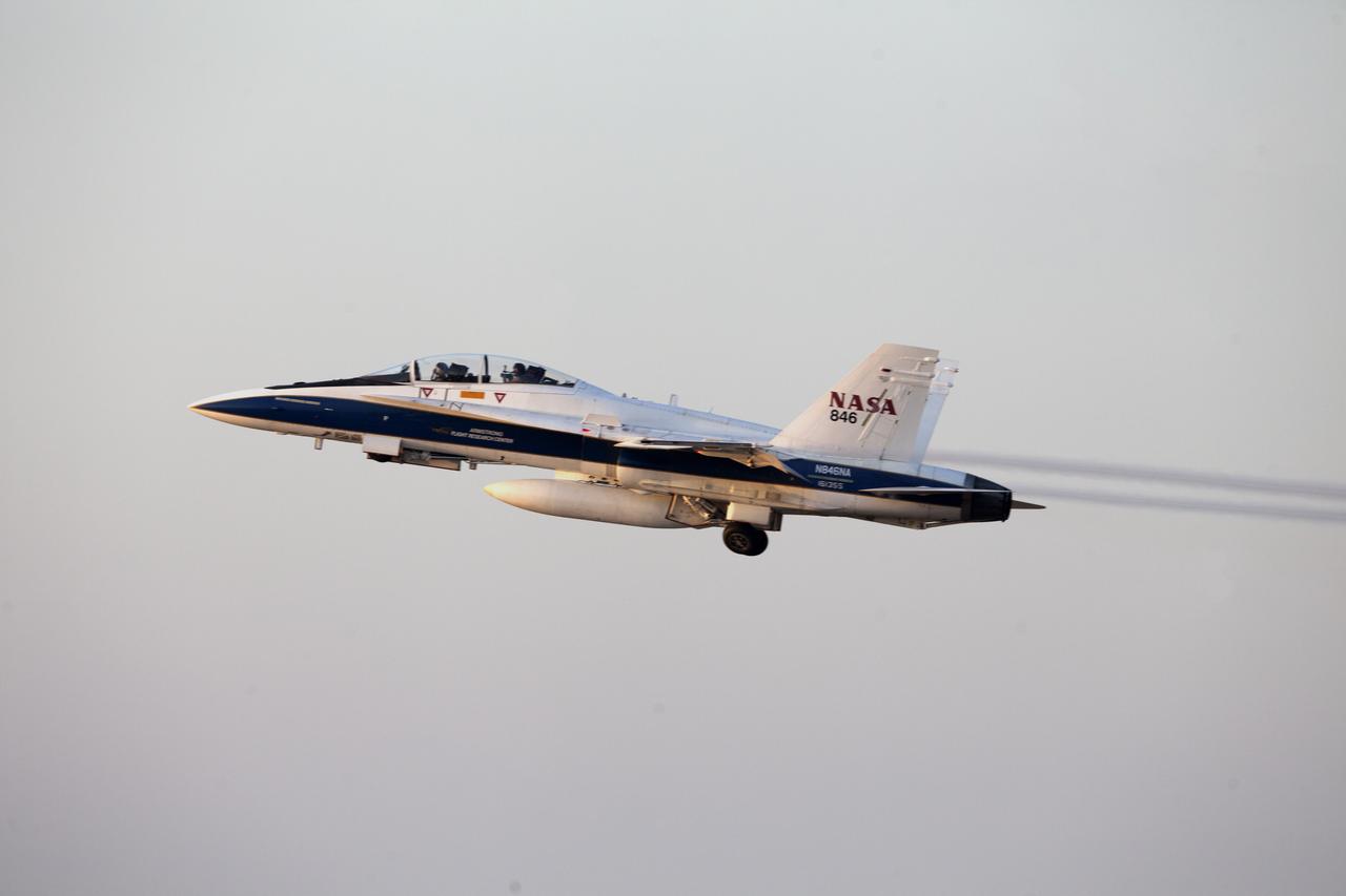
A pathfinder aircraft gains altitude after takeoff from the Skid Strip at Cape Canaveral Air Force Station in Florida. The airplane will provide photographic and video imagery of the Orbital ATK L-1011 Stargazer aircraft carrying a Pegasus XL Rocket with eight NASA Cyclone Global Navigation Satellite System, or CYGNSS, spacecraft. With the aircraft flying off shore, the Pegasus rocket will be released. Five seconds later, the solid propellant engine will ignite and boost the eight hurricane observatories to orbit. The eight CYGNSS satellites will make frequent and accurate measurements of ocean surface winds throughout the life cycle of tropical storms and hurricanes.
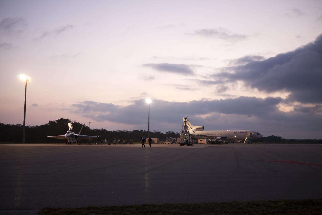
A pathfinder aircraft, at left, prepares for takeoff from the Skid Strip at Cape Canaveral Air Force Station in Florida. The airplane will provide photographic and video imagery of the Orbital ATK L-1011 Stargazer aircraft, in view at right, carrying a Pegasus XL Rocket with eight NASA Cyclone Global Navigation Satellite System, or CYGNSS, spacecraft. With the aircraft flying off shore, the Pegasus rocket will be released. Five seconds later, the solid propellant engine will ignite and boost the eight hurricane observatories to orbit. The eight CYGNSS satellites will make frequent and accurate measurements of ocean surface winds throughout the life cycle of tropical storms and hurricanes.
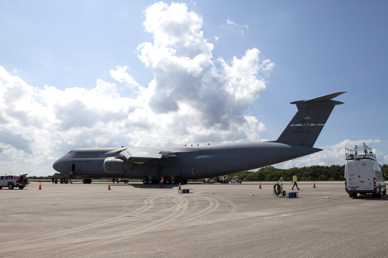
An Air Force C-5 Galaxy transport plane rolls to a stop at the Shuttle Landing Facility at NASA's Kennedy Space Center in Florida to deliver the GOES-R spacecraft for launch processing. The GOES series are weather satellites operated by NOAA to enhance forecasts. The spacecraft is to launch aboard a United Launch Alliance Atlas V rocket in November.
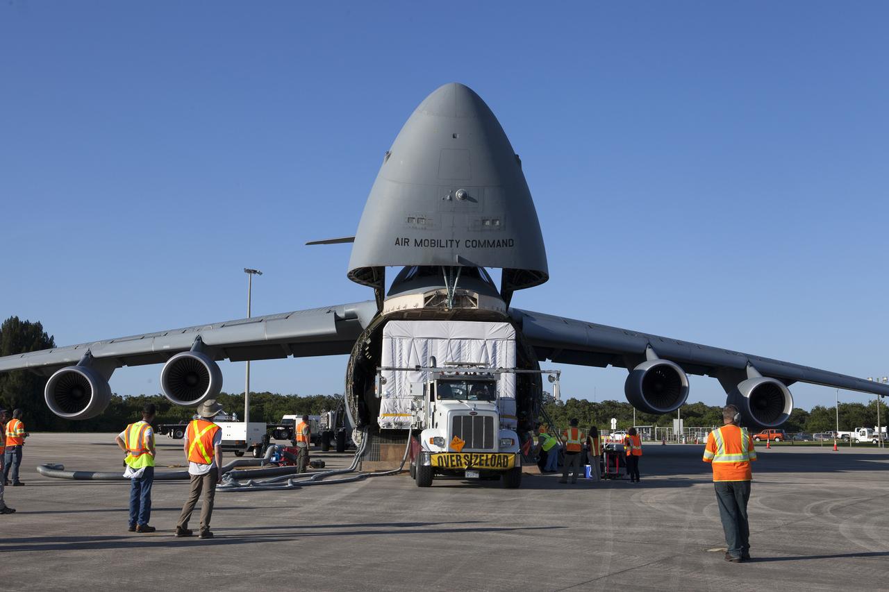
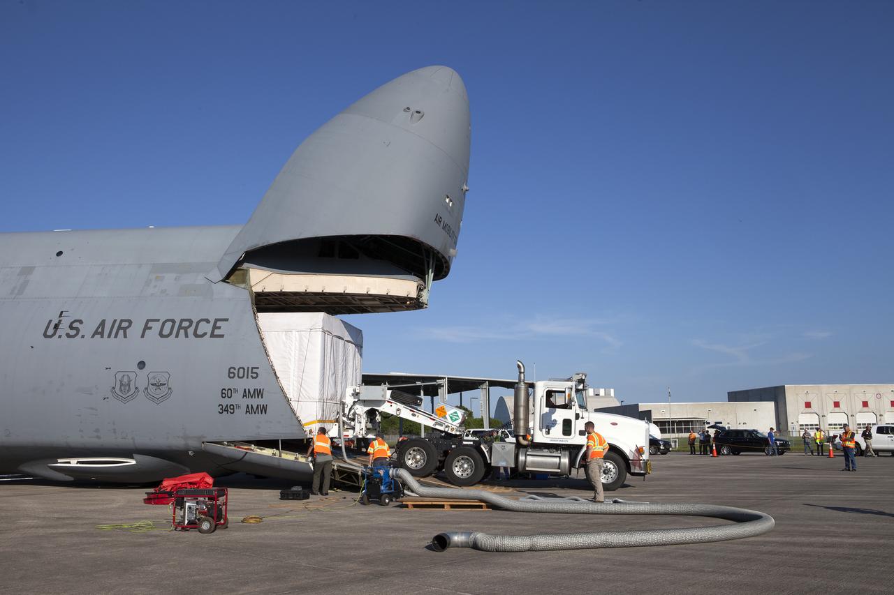
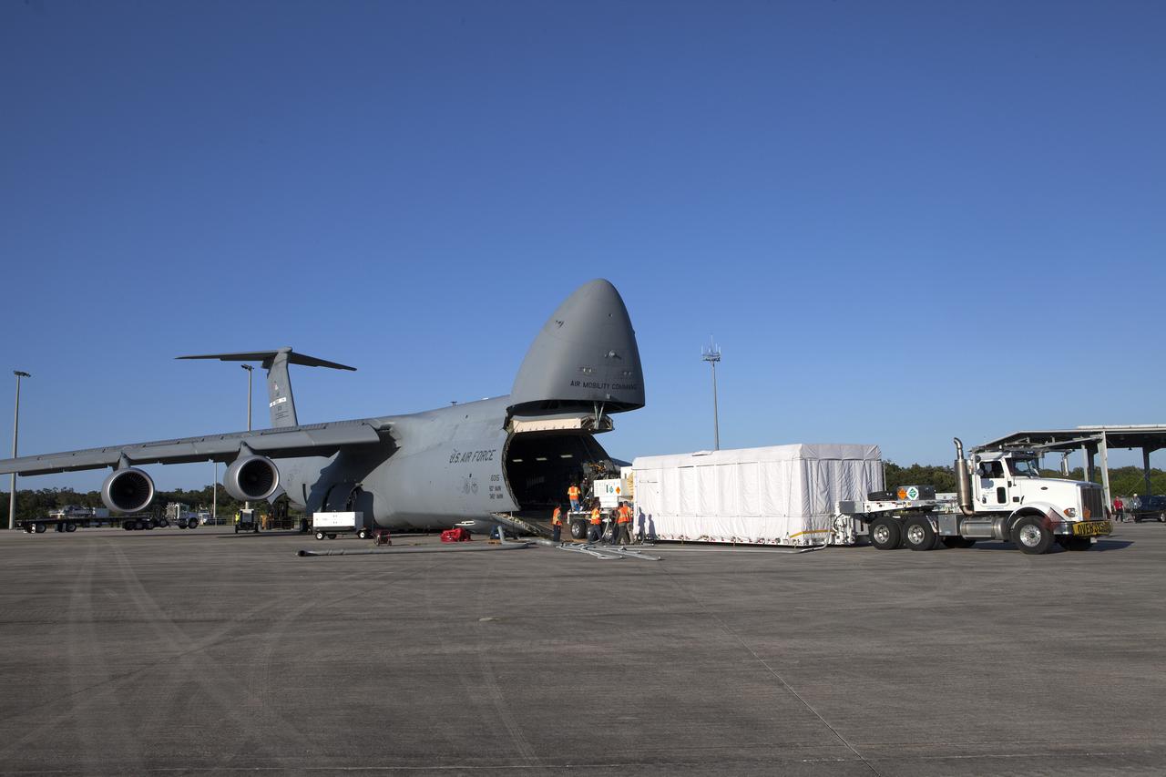
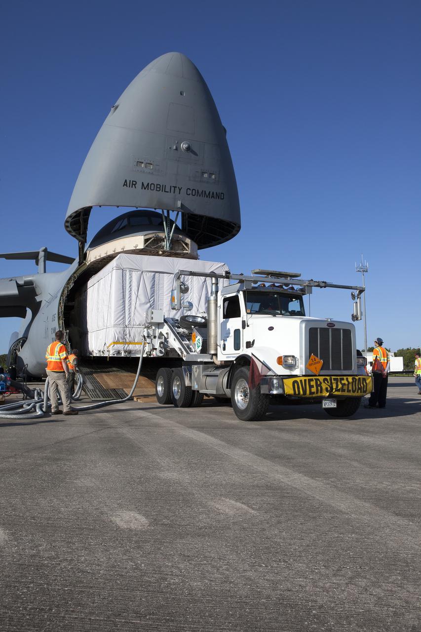
A truck with a specialized transporter drives out of the cargo hold of an Air Force C-5 Galaxy transport plane at the Shuttle Landing Facility at NASA's Kennedy Space Center in Florida to deliver the GOES-R spacecraft for launch processing. The GOES series are weather satellites operated by NOAA to enhance forecasts. The spacecraft is to launch aboard a United Launch Alliance Atlas V rocket in November.
A truck with a specialized transporter drives out of the cargo hold of an Air Force C-5 Galaxy transport plane at the Shuttle Landing Facility at NASA's Kennedy Space Center in Florida to deliver the GOES-R spacecraft for launch processing. The GOES series are weather satellites operated by NOAA to enhance forecasts. The spacecraft is to launch aboard a United Launch Alliance Atlas V rocket in November.
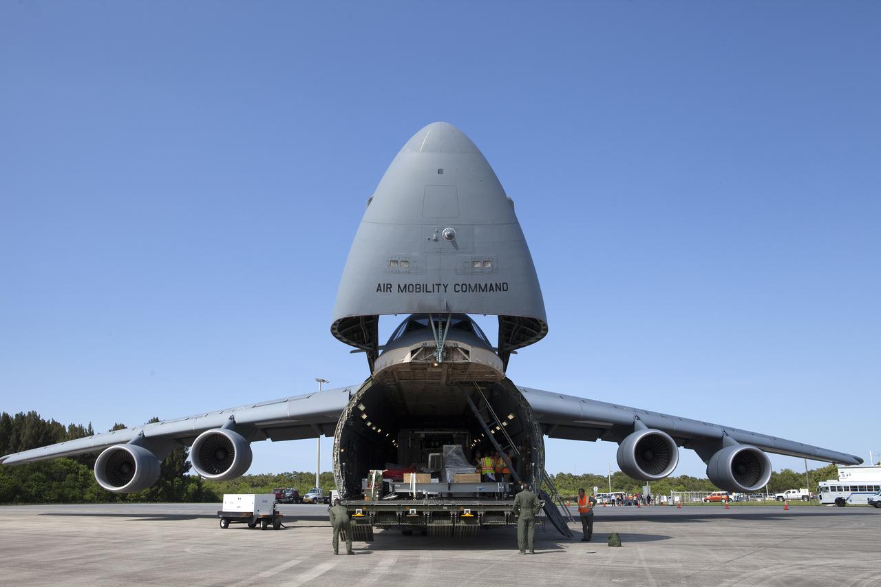
An Air Force C-5 Galaxy transport plane opens its nose section at the Shuttle Landing Facility at NASA's Kennedy Space Center in Florida to deliver the GOES-R spacecraft for launch processing. The GOES series are weather satellites operated by NOAA to enhance forecasts. The spacecraft is to launch aboard a United Launch Alliance Atlas V rocket in November.

A truck with a specialized transporter drives out of the cargo hold of an Air Force C-5 Galaxy transport plane at the Shuttle Landing Facility at NASA's Kennedy Space Center in Florida to deliver the GOES-R spacecraft for launch processing. The GOES series are weather satellites operated by NOAA to enhance forecasts. The spacecraft is to launch aboard a United Launch Alliance Atlas V rocket in November.
A truck with a specialized transporter drives out of the cargo hold of an Air Force C-5 Galaxy transport plane at the Shuttle Landing Facility at NASA's Kennedy Space Center in Florida to deliver the GOES-R spacecraft for launch processing. The GOES series are weather satellites operated by NOAA to enhance forecasts. The spacecraft is to launch aboard a United Launch Alliance Atlas V rocket in November.
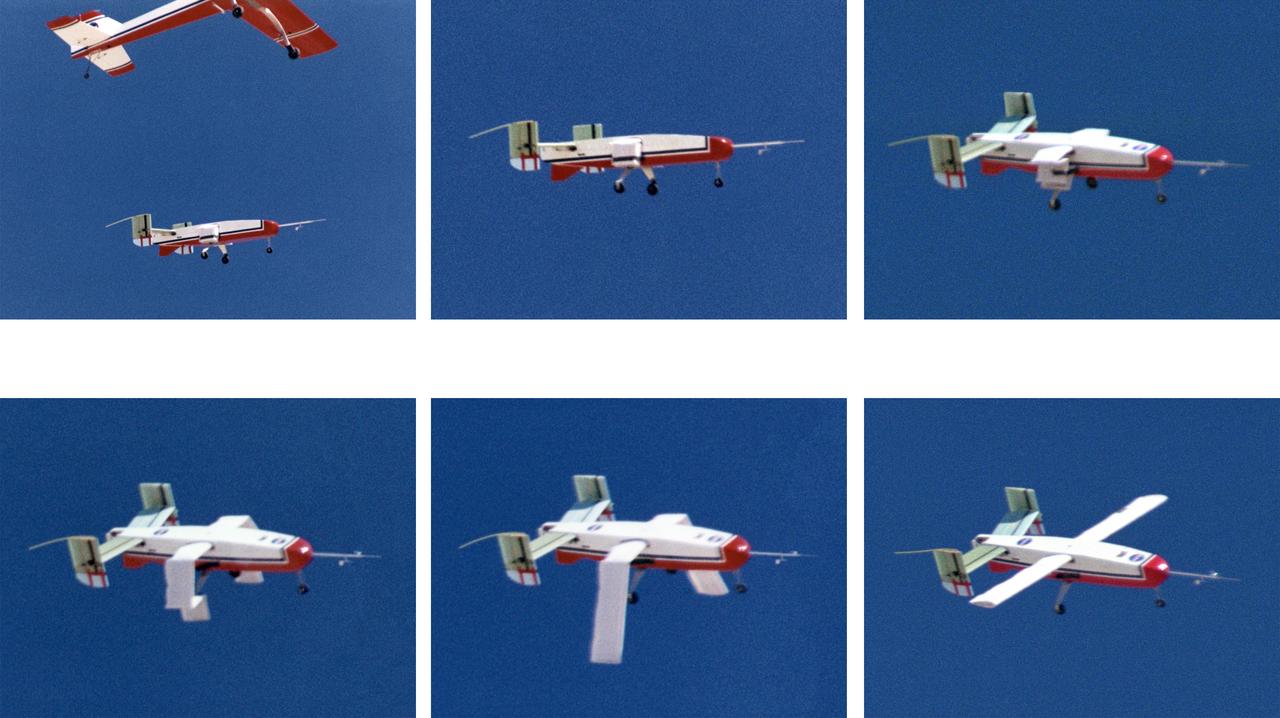
Wing Deployment Sequence #3: The deployable, inflatable wing technology demonstrator experiment aircraft's wings fully deployed during flight following separation from its carrier aircraft during a flight conducted by the NASA Dryden Flight Research Center, Edwards, Californiaornia. The inflatable wing project represented a basic flight research effort by Dryden personnel. Three successful flights of the I2000 inflatable wing aircraft occurred. During the flights, the team air-launched the radio-controlled (R/C) I2000 from an R/C utility airplane at an altitude of 800-1000 feet. As the I2000 separated from the carrier aircraft, its inflatable wings "popped-out," deploying rapidly via an on-board nitrogen bottle. The aircraft remained stable as it transitioned from wingless to winged flight. The unpowered I2000 glided down to a smooth landing under complete control.
The deployable, inflatable wing technology demonstrator aircraft's wings begin deploying following separation from its carrier aircraft during a flight experiment conducted by the NASA Dryden Flight Research Center, Edwards, California. Wing deployment time is typically on the order of a third of a second, almost faster than the human eye can see. Three successful flights of the I2000 inflatable wing aircraft occurred. During the flights, the team air-launched the radio-controlled (R/C) I2000 from an R/C utility airplane at an altitude of 800-1000 feet. As the I2000 separated from the carrier aircraft, its inflatable wings "popped-out," deploying rapidly via an on-board nitrogen bottle. The aircraft remained stable as it transitioned from wingless to winged flight. The unpowered I2000 glided down to a smooth landing under complete control.
Wing Deployment Sequence #2: The deployable, inflatable wing technology demonstrator experiment aircraft's wings continue deploying following separation from its carrier aircraft during a flight conducted by the NASA Dryden Flight Research Center, Edwards, California. The inflatable wing project represented a basic flight research effort by Dryden personnel. Three successful flights of the I2000 inflatable wing aircraft occurred. During the flights, the team air-launched the radio-controlled (R/C) I2000 from an R/C utility airplane at an altitude of 800-1000 feet. As the I2000 separated from the carrier aircraft, its inflatable wings "popped-out," deploying rapidly via an on-board nitrogen bottle. The aircraft remained stable as it transitioned from wingless to winged flight. The unpowered I2000 glided down to a smooth landing under complete control.
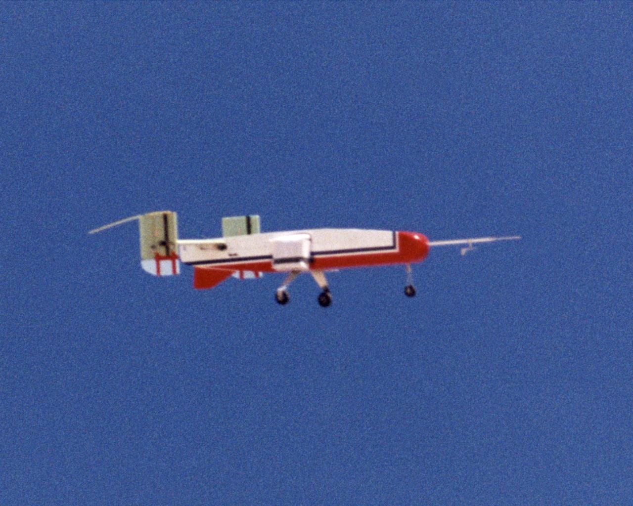
The deployable, inflatable wing technology demonstrator experiment aircraft maintains a steady attitude following separation from its carrier aircraft during a flight conducted by the NASA Dryden Flight Research Center, Edwards, California. The inflatable wing project represented a basic flight research effort by Dryden personnel. Three successful flights of the I2000 inflatable wing aircraft occurred. During the flights, the team air-launched the radio-controlled (R/C) I2000 from an R/C utility airplane at an altitude of 800-1000 feet. As the I2000 separated from the carrier aircraft, its inflatable wings "popped-out," deploying rapidly via an on-board nitrogen bottle. The aircraft remained stable as it transitioned from wingless to winged flight. The unpowered I2000 glided down to a smooth landing under complete control.
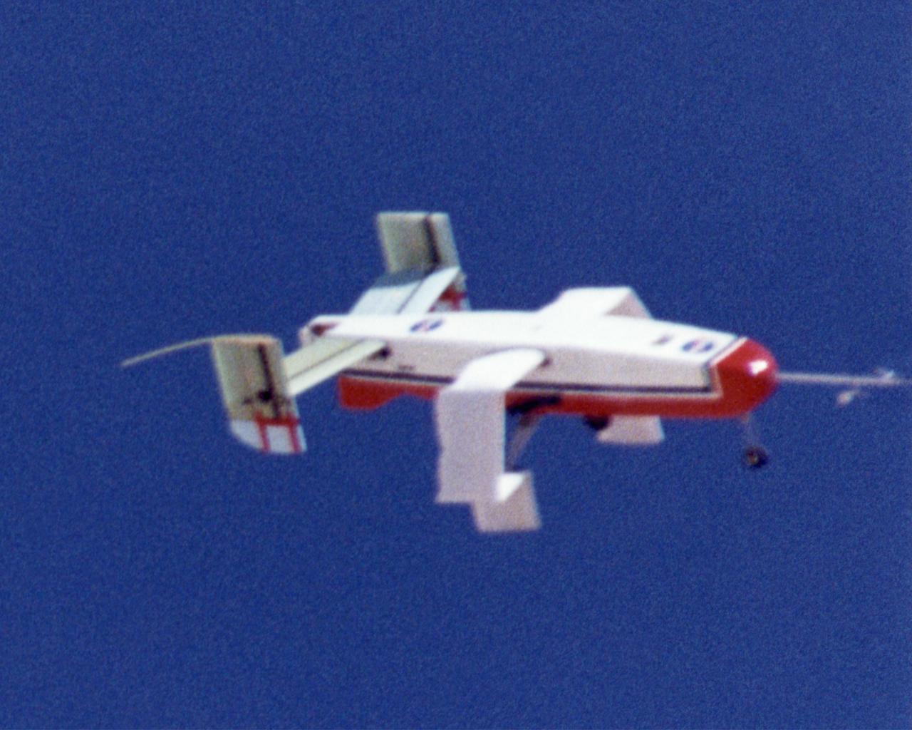
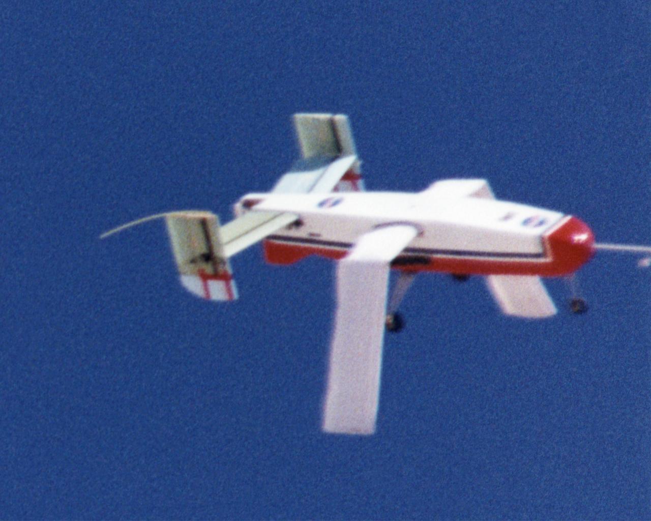
Wing Deployment Sequence #1: The deployable, inflatable wing technology demonstrator experiment aircraft's wings begin deploying following separation from its carrier aircraft during a flight conducted by the NASA Dryden Flight Research Center, Edwards, California. The inflatable wing project represented a basic flight research effort by Dryden personnel. Three successful flights of the I2000 inflatable wing aircraft occurred. During the flights, the team air-launched the radio-controlled (R/C) I2000 from an R/C utility airplane at an altitude of 800-1000 feet. As the I2000 separated from the carrier aircraft, its inflatable wings "popped-out," deploying rapidly via an on-board nitrogen bottle. The aircraft remained stable as it transitioned from wingless to winged flight. The unpowered I2000 glided down to a smooth landing under complete control.
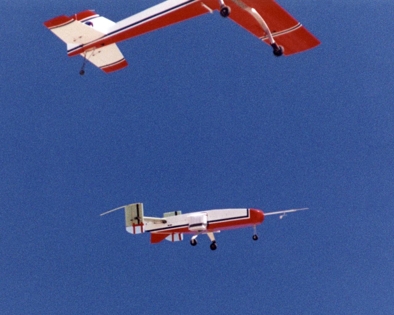
The deployable, inflatable wing technology demonstrator experiment separates from its carrier aircraft during a flight conducted by the NASA Dryden Flight Research Center, Edwards, California. The inflatable wing project represented a basic flight research effort by Dryden personnel. Three successful flights of the I2000 inflatable wing aircraft occurred. During the flights, the team air-launched the radio-controlled (R/C) I2000 from an R/C utility airplane at an altitude of 800-1000 feet. As the I2000 separated from the carrier aircraft, its inflatable wings "popped-out," deploying rapidly via an on-board nitrogen bottle. The aircraft remained stable as it transitioned from wingless to winged flight. The unpowered I2000 glided down to a smooth landing under complete control.
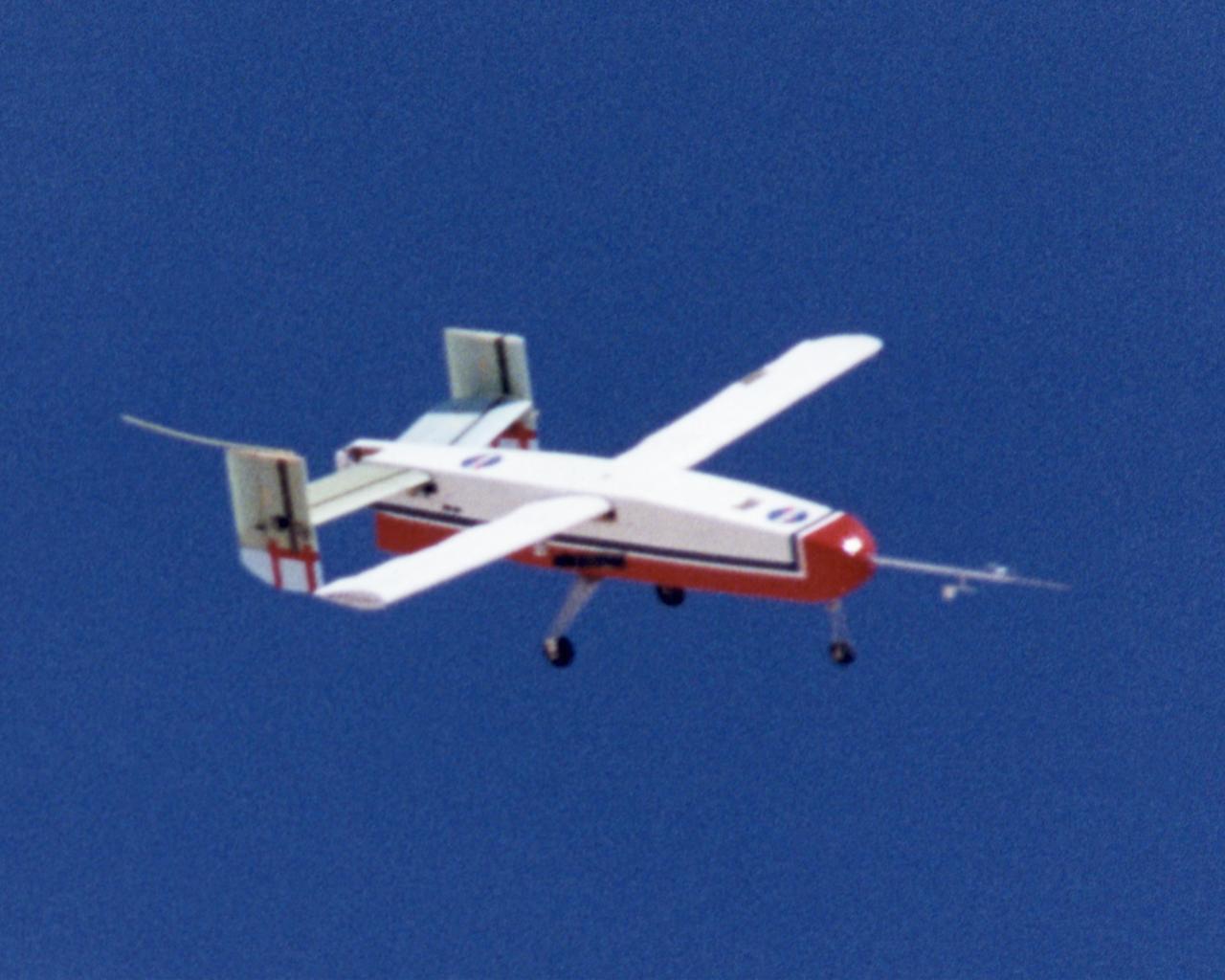
The deployable, inflatable wing technology demonstrator experiment aircraft looks good during a flight conducted by the NASA Dryden Flight Research Center, Edwards, California. The inflatable wing project represented a basic flight research effort by Dryden personnel. Three successful flights of the I2000 inflatable wing aircraft occurred. During the flights, the team air-launched the radio-controlled (R/C) I2000 from an R/C utility airplane at an altitude of 800-1000 feet. As the I2000 separated from the carrier aircraft, its inflatable wings "popped-out," deploying rapidly via an on-board nitrogen bottle. The aircraft remained stable as it transitioned from wingless to winged flight. The unpowered I2000 glided down to a smooth landing under complete control.

The XV-15 tilt rotor ships #1 and #2 parked on the NASA Dryden Flight Research Center ramp. The XV-15s, manufactured by Bell, were involved in limited research at Dryden in 1980 and 1981. The development of the XV-15 Tiltrotor research aircraft was initiated in 1973 with joint Army/NASA funding as a "proof of concept", or "technology demonstrator" program, with two aircraft being built by Bell Helicopter Textron (BHT) in 1977. The aircraft are powered by twin Lycoming T-53 turboshaft engines that are connected by a cross-shaft and drive three-bladed, 25 ft diameter metal rotors (the size extensively tested in a wind tunnel). The engines and main transmissions are located in wingtip nacelles to minimize the operational loads on the cross-shaft system and, with the rotors, tilt as a single unit. For takeoff, the proprotors and their engines are used in the straight-up position where the thrust is directed downward. The XV-15 then climbs vertically into the air like a helicopter. In this VTOL mode, the vehicle can lift off and hover for approximately one hour. Once off the ground, the XV-15 has the ability to fly in one of two different modes. It can fly as a helicopter, in the partially converted airplane mode. The XV-15 can also then convert from the helicopter mode to the airplane mode. This is accomplished by continuous rotation of the proprotors from the helicopter rotor position to the conventional airplane propeller position. During the ten to fifteen second conversion period, the aircraft speed increases and lift is transferred from the rotors to the wing. To land, the proprotors are rotated up to the helicopter rotor position and flown as a helicopter to a vertical landing.
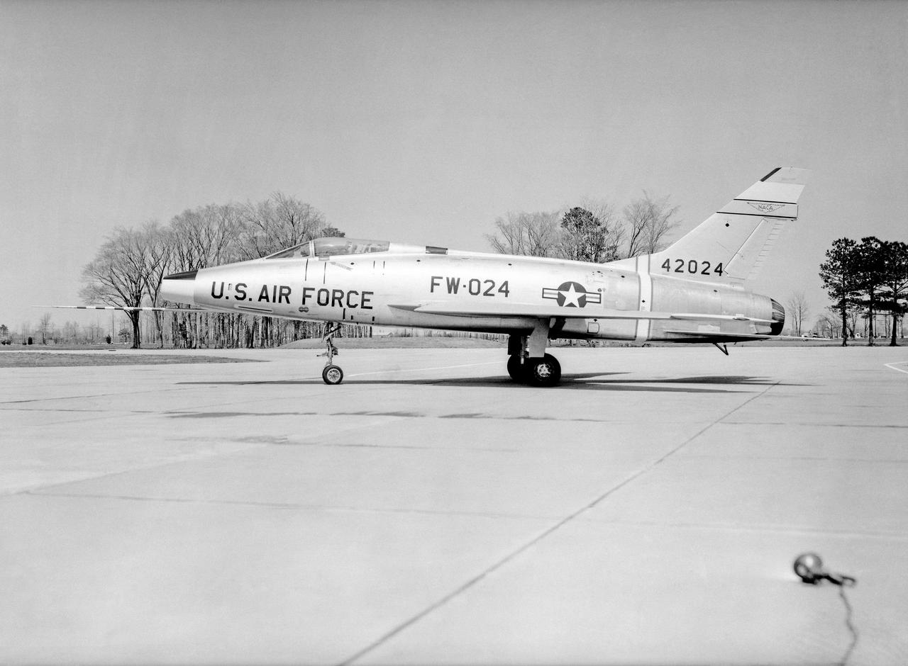
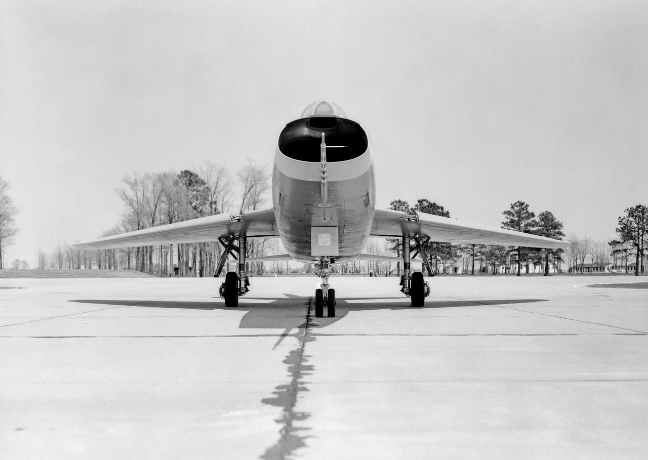
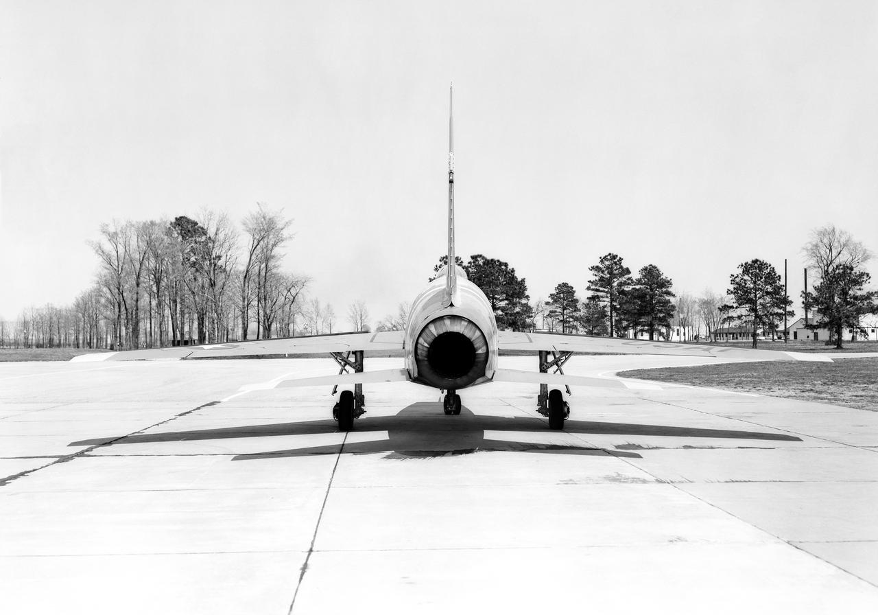
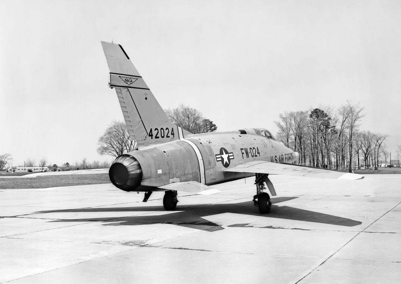
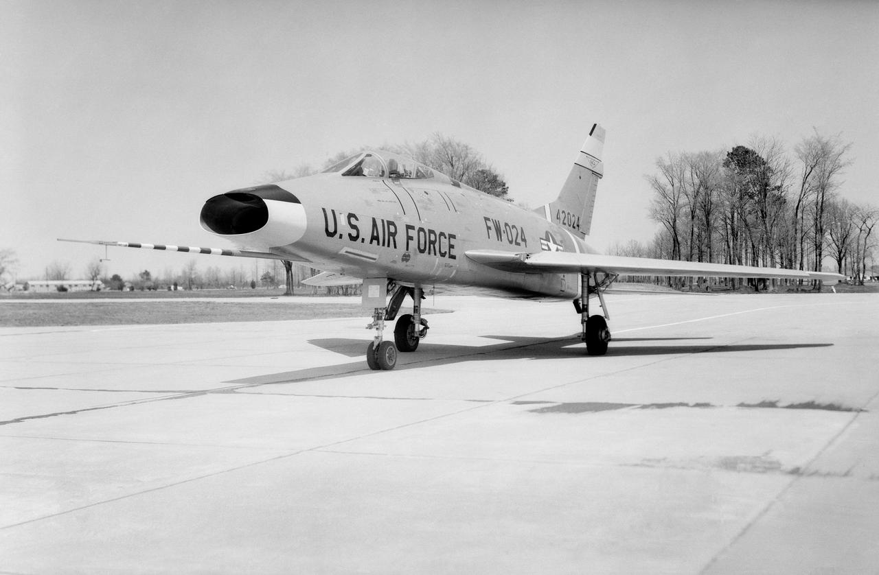
North American F-100 C airplane used in sonic boom investigation at Wallops, October 7, 1958. Photograph published in: A New Dimension Wallops Island Flight Test Range: The First Fifteen Years by Joseph Shortal. A NASA publication. Page 672. -- Aircraft number: NACA 42024. Side view, 3/4 view from front, 3/4 view from rear, rear view, and two front views.
North American F-100 C airplane used in sonic boom investigation at Wallops, October 7, 1958. Photograph published in: A New Dimension Wallops Island Flight Test Range: The First Fifteen Years by Joseph Shortal. A NASA publication. Page 672. -- Aircraft number: NACA 42024. Side view, 3/4 view from front, 3/4 view from rear, rear view, and two front views.
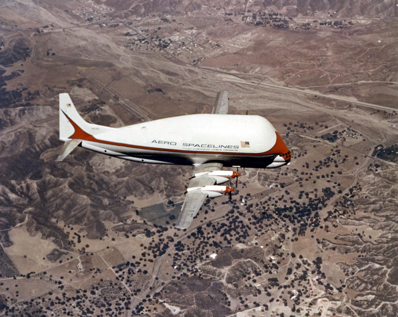
Super Guppy, bigger sister of the aptly named Pregnant Guppy, was the only airplane in the world capable of carrying a complete S-IVB stage. This aircraft was built by John M. Conroy of Aero Spaceliners, Incorporated, who started with the fuselages of a surplus Boeing C-97 Stratocruiser, ballooned out the upper decks enormously, and hinged the front sections so that they could be folded back 110 degrees. The Super Guppy flew smoothly at a 250-mph cruising speed, and its cargo deck provided a 25-foot clear diameter.
North American F-100 C airplane used in sonic boom investigation at Wallops, October 7, 1958. Photograph published in: A New Dimension Wallops Island Flight Test Range: The First Fifteen Years by Joseph Shortal. A NASA publication. Page 672. -- Aircraft number: NACA 42024. Side view, 3/4 view from front, 3/4 view from rear, rear view, and two front views.
North American F-100 C airplane used in sonic boom investigation at Wallops, October 7, 1958. Photograph published in: A New Dimension Wallops Island Flight Test Range: The First Fifteen Years by Joseph Shortal. A NASA publication. Page 672. -- Aircraft number: NACA 42024. Side view, 3/4 view from front, 3/4 view from rear, rear view, and two front views.
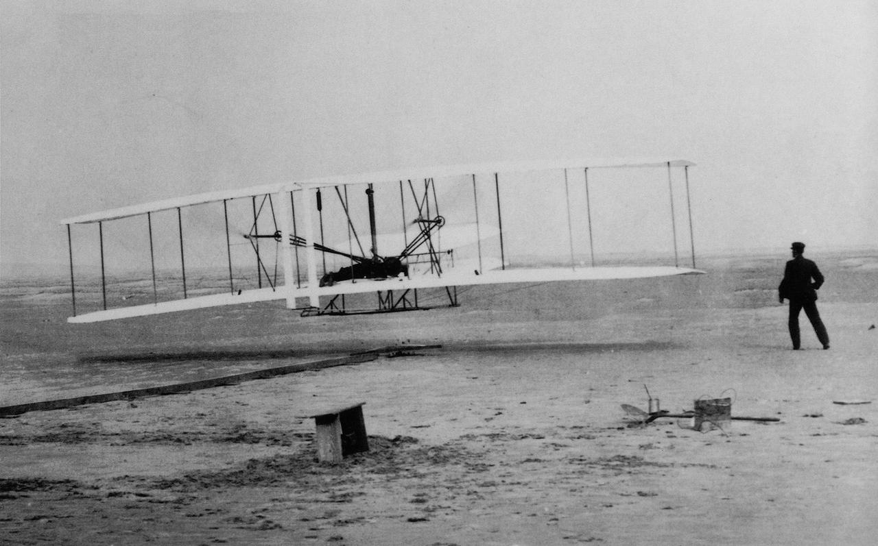
On December 17, 1903, two brothers from Dayton, Ohio, named Wilbur and Orville Wright, were successful in flying an airplane they built. Their powered aircraft flew for 12 seconds above the sand dunes of Kitty Hawk, North Carolina, making them the first men to pilot a heavier-than-air machine that took off on its own power, remained under control, and sustained flight.
This panoramic side view of NASA’s X-59 Quiet SuperSonic Technology airplane shows the aircraft sitting on jacks at a Lockheed Martin test facility in Fort Worth, Texas. Lockheed Martin Aeronautics Company - Fort Worth - Chris Hanoch Subject: SEG 230 Nose Attachement FP#: 21-03420 POC: Analiese Smith, Chris Higgins Other info: X-59 in Fort Worth, testing
North American F-100 C airplane used in sonic boom investigation at Wallops, October 7, 1958. Photograph published in: A New Dimension Wallops Island Flight Test Range: The First Fifteen Years by Joseph Shortal. A NASA publication. Page 672. -- Aircraft number: NACA 42024. Side view, 3/4 view from front, 3/4 view from rear, rear view, and two front views.
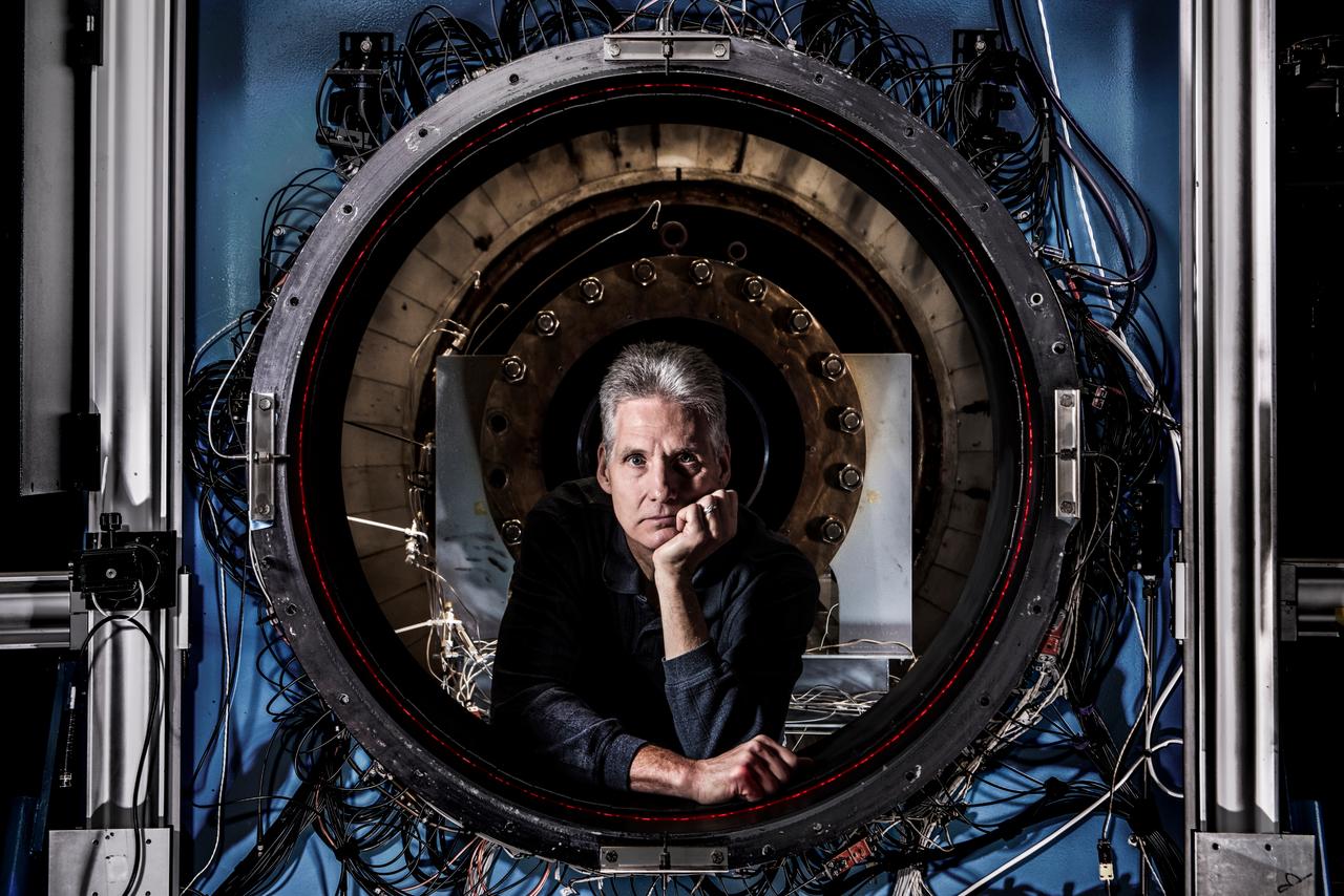
How do you measure a cloud? Tim Bencic does it with lasers. The NASA Glenn engineer invented a tomography system for our Propulsion Systems Lab to help understand the dangers of ice crystal icing on airplanes. Bencic’s system, affectionally called “Tim-ography” is like a CAT Scan. The laser light within its circular geometry bounces off the surface of ice particles in the cloud and fiber optic detectors map out its properties. This tool is helping NASA’s researchers make aircraft safer in challenging weather conditions.
North American F-100 C airplane used in sonic boom investigation at Wallops, October 7, 1958. Photograph published in: A New Dimension Wallops Island Flight Test Range: The First Fifteen Years by Joseph Shortal. A NASA publication. Page 672. -- Aircraft number: NACA 42024. Side view, 3/4 view from front, 3/4 view from rear, rear view, and two front views.
![ISS008-E-13304 (28 January 2004) --- This image featuring Mt. Everest and Makalu was taken by an Expedition 8 crewmember on the International Space Station (ISS). Crewmembers on board the Station have a unique view of the world because of their position in a low orbit (200 nautical miles, 360 kilometers) relative to satellites and their ability to look at any angle out the windows of the spacecraft. ISS crewmembers recently took advantage of their vantage point to photograph this oblique view of the Himalayas looking south from over the Tibetan Plateau. At first glance, one might think that the image looks like a picture taken from an airplane; until you remember that the summits of Makalu [left (8,462 meters: 27,765 feet)] and Everest [right (8,850 meters; 29,035 feet)] are at the heights typically flown by commercial aircraft, and could never be seen this way from an airplane.](https://images-assets.nasa.gov/image/iss008e13304/iss008e13304~medium.jpg)
ISS008-E-13304 (28 January 2004) --- This image featuring Mt. Everest and Makalu was taken by an Expedition 8 crewmember on the International Space Station (ISS). Crewmembers on board the Station have a unique view of the world because of their position in a low orbit (200 nautical miles, 360 kilometers) relative to satellites and their ability to look at any angle out the windows of the spacecraft. ISS crewmembers recently took advantage of their vantage point to photograph this oblique view of the Himalayas looking south from over the Tibetan Plateau. At first glance, one might think that the image looks like a picture taken from an airplane; until you remember that the summits of Makalu [left (8,462 meters: 27,765 feet)] and Everest [right (8,850 meters; 29,035 feet)] are at the heights typically flown by commercial aircraft, and could never be seen this way from an airplane.
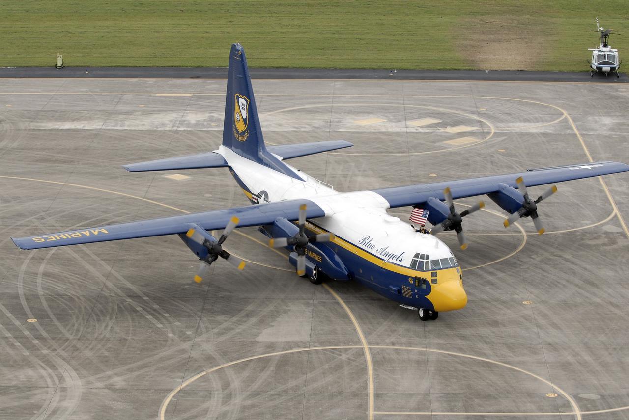
CAPE CANAVERAL, Fla. – A C-130 airplane flown by U.S. Marines lands at the Shuttle Landing Facility at NASA's Kennedy Space Center in Florida. The plane carries the support team for the U.S. Navy's Blue Angels, who are going to perform at the Kennedy Space Center Visitor Complex Space and Air Show Nov. 8-9. The Navy's elite flight demonstration squadron will take to the skies in military aircraft demonstrations by the F-16 Fighting Falcon and F/A-18 Super Hornet jets for the second annual Space & Air Show at Kennedy. This year’s show brings together the best in military aircraft, coupled with precision pilots and veteran astronauts to celebrate spaceflight and aviation. The event includes military aircraft demonstrations by the F-16 Fighting Falcon and a water rescue demonstration by the 920th Rescue Wing. Photo credit: NASA/Kim Shiflett
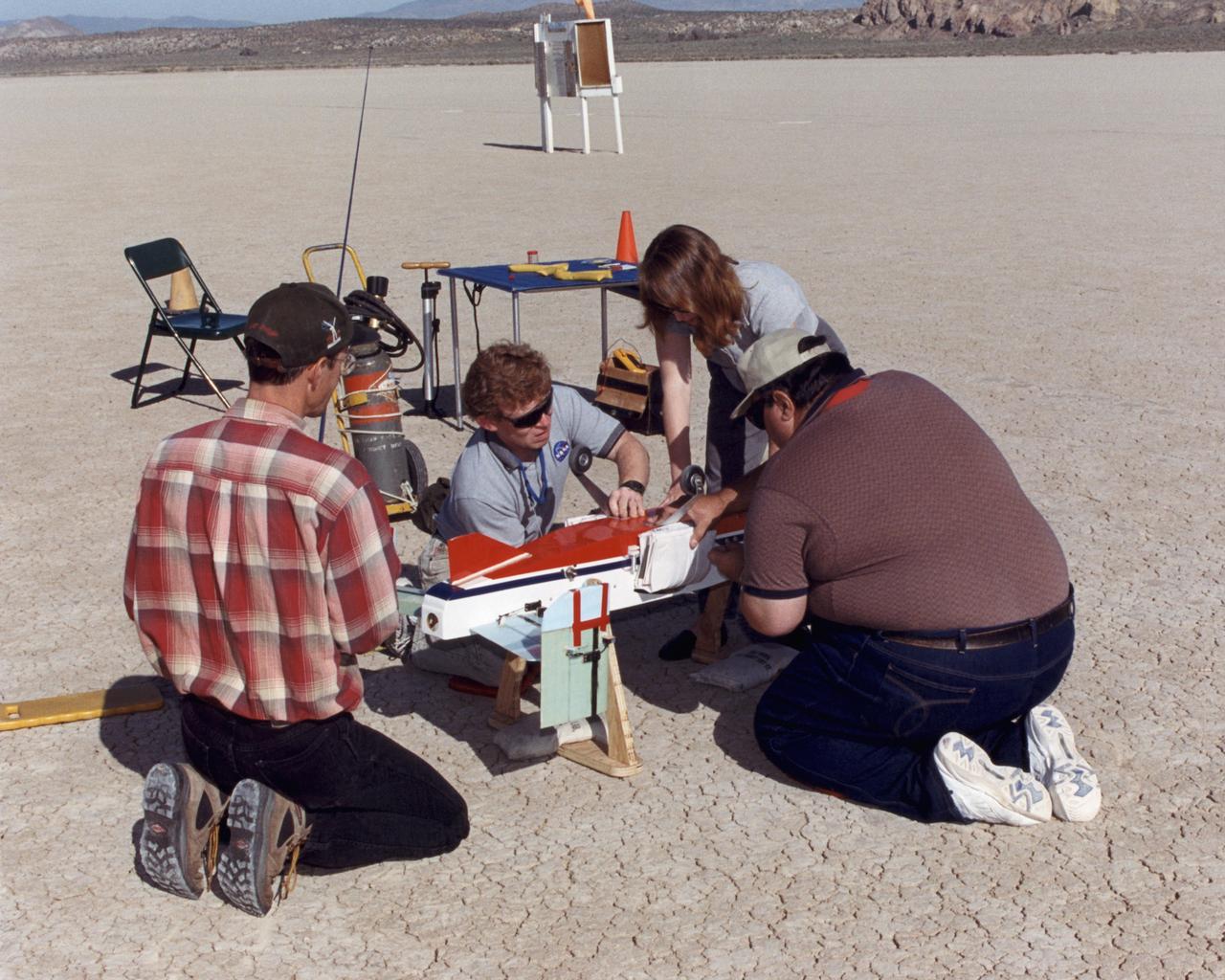
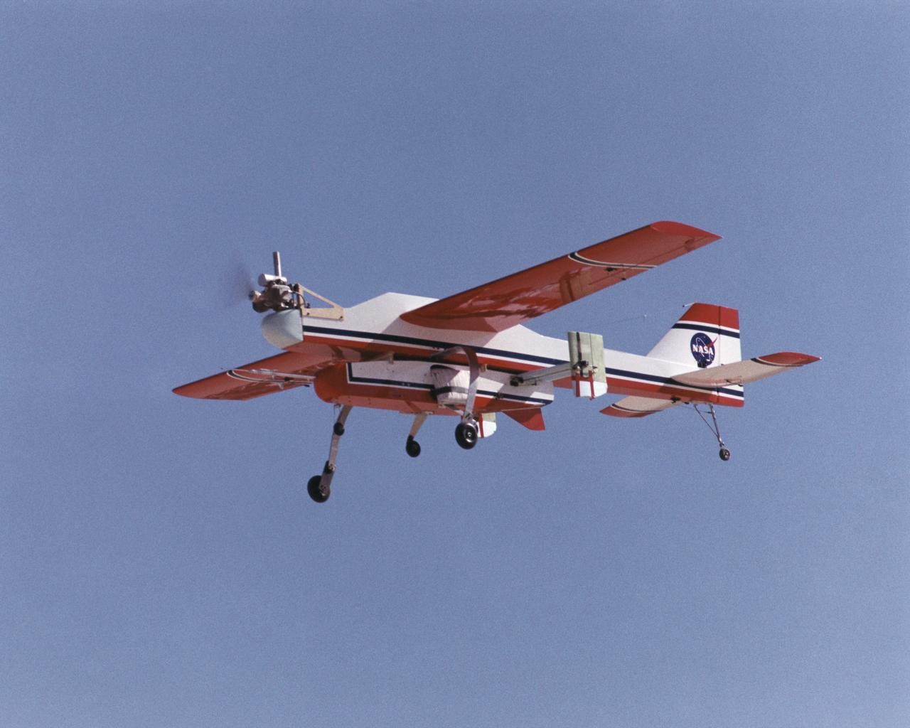
Inflatable Wing project personnel prepare a deployable, inflatable wing technology demonstrator experiment flown by the NASA Dryden Flight Research Center, Edwards, California. The inflatable wing project represented a basic flight research effort by Dryden personnel. Three successful flights of the I2000 inflatable wing aircraft occurred. During the flights, the team air-launched the radio-controlled (R/C) I2000 from an R/C utility airplane at an altitude of 800-1000 feet. As the I2000 separated from the carrier aircraft, its inflatable wings "popped-out," deploying rapidly via an on-board nitrogen bottle. The aircraft remained stable as it transitioned from wingless to winged flight. The unpowered I2000 glided down to a smooth landing under complete control.

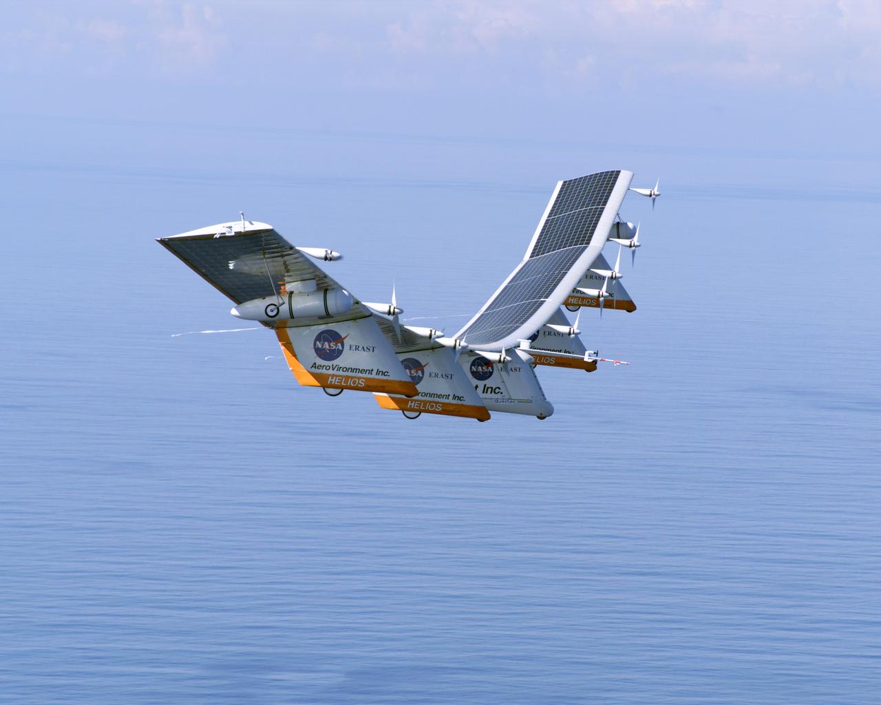
The takeoff set the stage for a two-day Helios endurance flight in the stratosphere planned for mid-July. The Helios wing, spanning 247 feet and weighing about 2,400 pounds, is giving NASA and industry engineers confidence that remotely piloted aircraft will be able to stay aloft for weeks at a time, providing environmental monitoring capabilities and telecommunications relay services Helios is an all-electric airplane. In addition to being non-polluting, Helios can fly above storms, and use the power of the sun to stay aloft during daylight. Key to the success of this type of aircraft is the ability to fly in darkness, using fuel cells when sunlight cannot furnish energy. Helios flew over the Navy's Pacific Missile Range Facility where favorable sun exposure and test ranges closed to other air traffic benefited the NASA research effort. In 2003 the aircraft was lost to a crash.
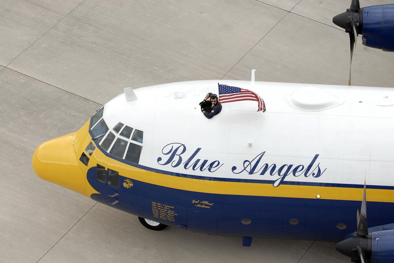
CAPE CANAVERAL, Fla. – A C-130 airplane flown by U.S. Marines stops at the Shuttle Landing Facility at NASA's Kennedy Space Center in Florida. The plane carries the support team for the U.S. Navy's Blue Angels, who are going to perform at the Kennedy Space Center Visitor Complex Space and Air Show Nov. 8-9. The Navy's elite flight demonstration squadron will take to the skies in military aircraft demonstrations by the F-16 Fighting Falcon and F/A-18 Super Hornet jets for the second annual Space & Air Show at Kennedy. This year’s show brings together the best in military aircraft, coupled with precision pilots and veteran astronauts to celebrate spaceflight and aviation. The event includes military aircraft demonstrations by the F-16 Fighting Falcon and a water rescue demonstration by the 920th Rescue Wing. Photo credit: NASA/Kim Shiflett
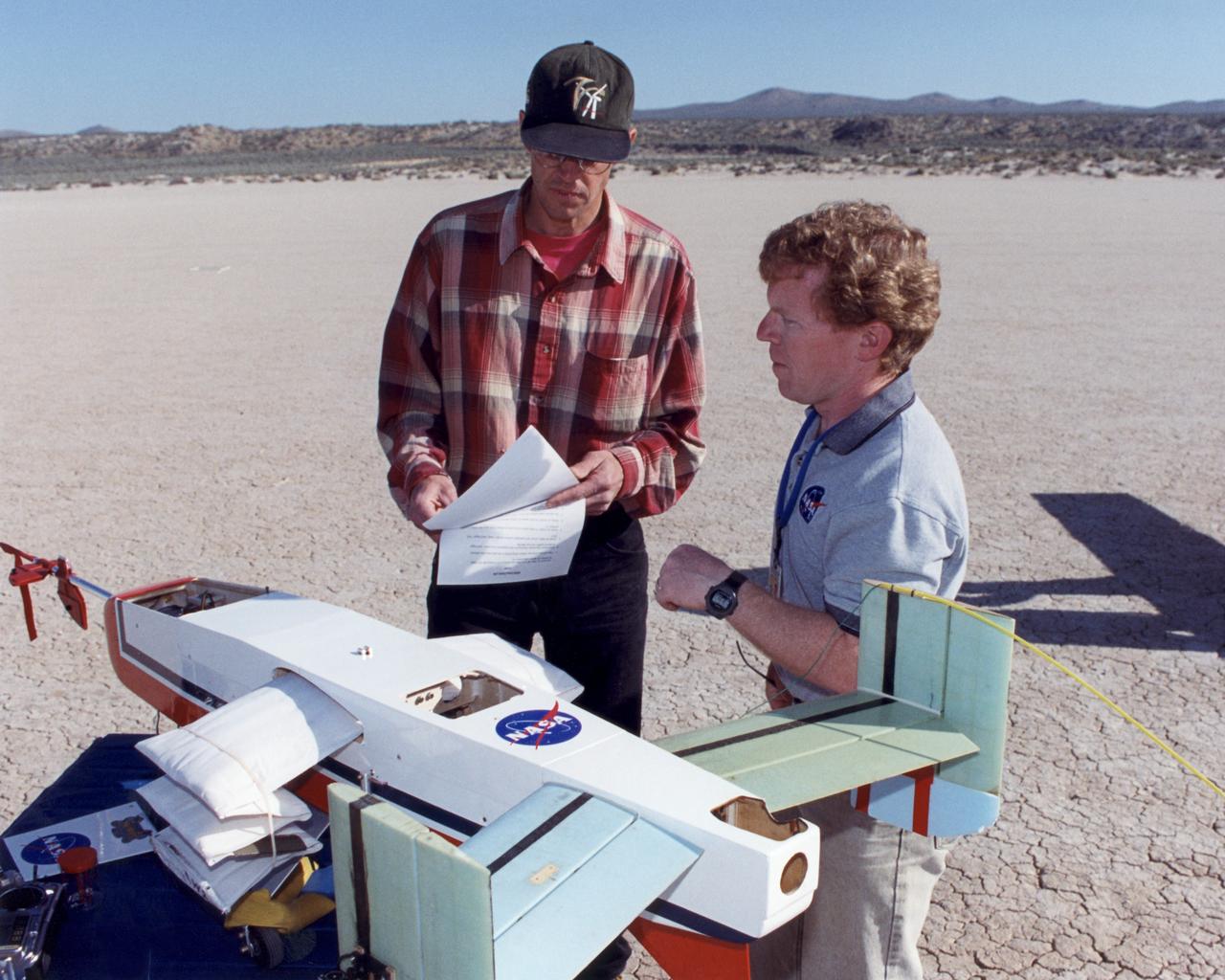
Engineers Jim Murray and Joe Pahle prepare a deployable, inflatable wing technology demonstrator experiment flown by the NASA Dryden Flight Research Center, Edwards, California. The inflatable wing project represented a basic flight research effort by Dryden personnel. Three successful flights of the I2000 inflatable wing aircraft occurred. During the flights, the team air-launched the radio-controlled (R/C) I2000 from an R/C utility airplane at an altitude of 800-1000 feet. As the I2000 separated from the carrier aircraft, its inflatable wings "popped-out," deploying rapidly via an on-board nitrogen bottle. The aircraft remained stable as it transitioned from wingless to winged flight. The unpowered I2000 glided down to a smooth landing under complete control.
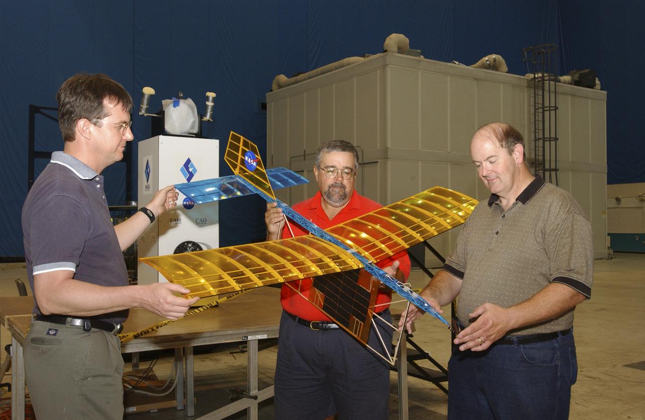
A team of NASA researchers from Marshall Space Flight Center (MSFC) and Dryden Flight Research center have proven that beamed light can be used to power an aircraft, a first-in-the-world accomplishment to the best of their knowledge. Using an experimental custom built radio-controlled model aircraft, the team has demonstrated a system that beams enough light energy from the ground to power the propeller of an aircraft and sustain it in flight. Special photovoltaic arrays on the plane, similar to solar cells, receive the light energy and convert it to electric current to drive the propeller motor. In a series of indoor flights this week at MSFC, a lightweight custom built laser beam was aimed at the airplane `s solar panels. The laser tracks the plane, maintaining power on its cells until the end of the flight when the laser is turned off and the airplane glides to a landing. The laser source demonstration represents the capability to beam more power to a plane so that it can reach higher altitudes and have a greater flight range without having to carry fuel or batteries, enabling an indefinite flight time. The demonstration was a collaborative effort between the Dryden Center at Edward's, California, where the aircraft was designed and built, and MSFC, where integration and testing of the laser and photovoltaic cells was done. Laser power beaming is a promising technology for consideration in new aircraft design and operation, and supports NASA's goals in the development of revolutionary aerospace technologies. Photographed with their invention are (from left to right): David Bushman and Tony Frackowiak, both of Dryden; and MSFC's Robert Burdine.

NASA research pilot Bill Dana stands in front of the HL-10 Lifting Body following his first glide flight on April 25, 1969. Dana later retired as Chief Engineer at NASA's Dryden Flight Research Center, (called the NASA Flight Research Center in 1969). Prior to his lifting body assignment, Dana flew the X-15 research airplane. He flew the rocket-powered aircraft 16 times, reaching a top speed of 3,897 miles per hour and a peak altitude of 310,000 feet (almost 59 miles high).
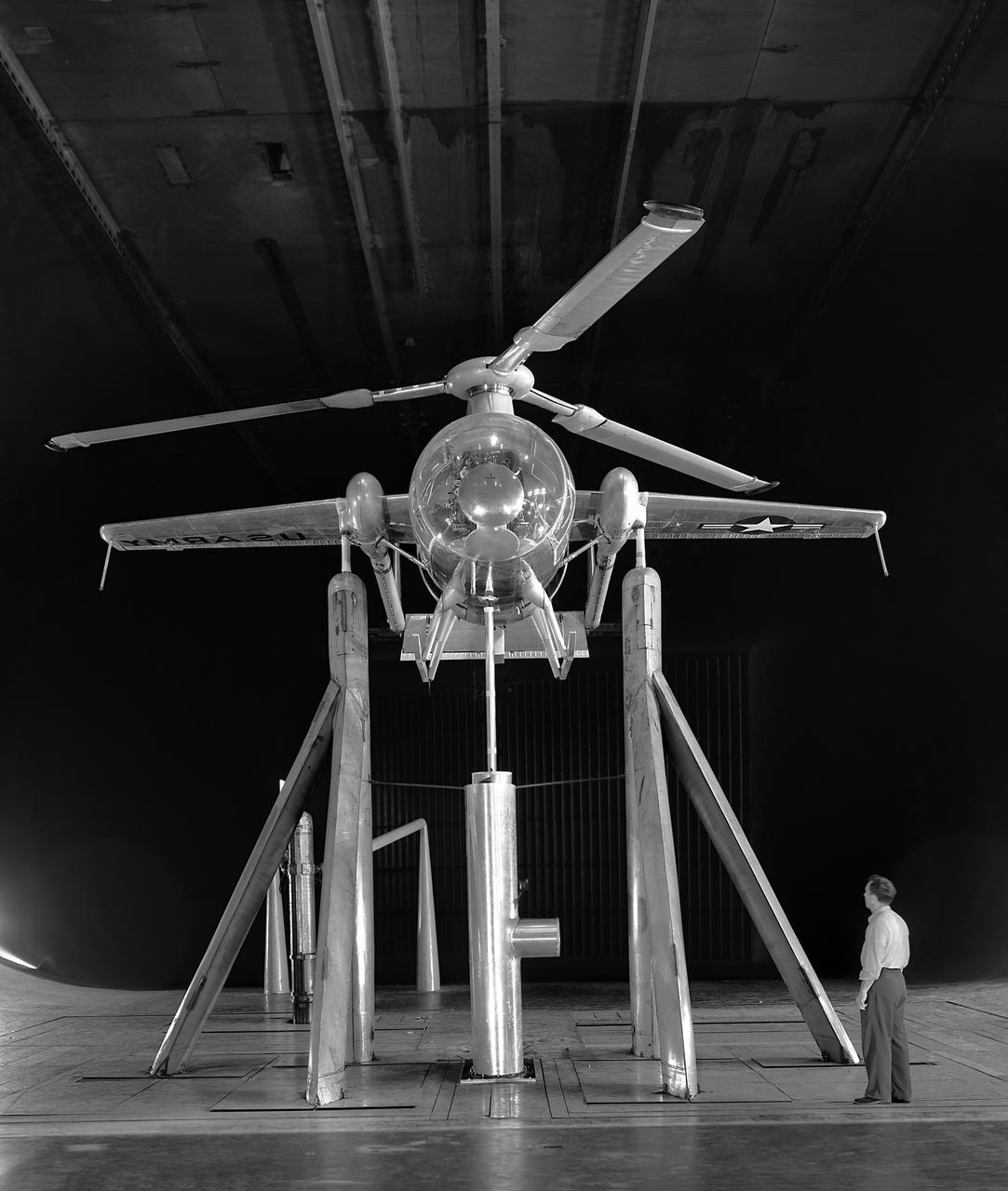
Foreword, front view of McDonnell Model XV-1 Convertiplane in the Ames 40x80 Foot Wind Tunnel. The McDonnell XV-1 was an experimental compound gyroplane developed for a joint research program between the United States Air Force and the United States Army to explore technologies to develop an aircraft that could take off and land like a helicopter but fly at faster airspeeds, similar to a conventional airplane. The XV-1 would reach a speed of 200 mph (322 km/h), faster than any previous rotorcraft, but the program was terminated due to the tip-jet noise and complexity of the technology which gave only a modest gain in performance.
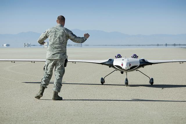
The X-56A Multi-Utility Technology Testbed (MUTT) is greeted on an Edwards Air Force Base runway by a U.S. Air Force Research Laboratory (AFRL) team member. NASA’s Armstrong Flight Research Center and the AFRL, along with participants from Langley Research Center and Glenn Research Center, and support from Lockheed Martin, are using the second X-56A (dubbed “Buckeye”) to check out aircraft systems, evaluate handling qualities, characterize and expand the airplane’s performance envelope, and verify pre-flight predictions regarding aircraft behavior. The 20-minute flight marked the beginning of a research effort designed to yield significant advances in aeroservoelastic technology using a low-cost, modular, remotely piloted aerial vehicle.

KENNEDY SPACE CENTER, FLA. -- NASA's "Super Guppy" aircraft arrives in KSC air space escorted by two T-38 aircraft after leaving Marshall Space Flight Center in Huntsville, Ala. The whale-like airplane carries the U.S. Laboratory module, considered the centerpiece of the International Space Station. The module will undergo final pre-launch preparations at KSC's Space Station Processing Facility. Scheduled for launch aboard the Shuttle Endeavour on mission STS-98, the laboratory comprises three cylindrical sections with two end cones. Each end-cone contains a hatch opening for entering and exiting the lab. The lab will provide a shirtsleeve environment for research in such areas as life science, microgravity science, Earth science and space science. Designated Flight 5A, this mission is targeted for launch in early 2000
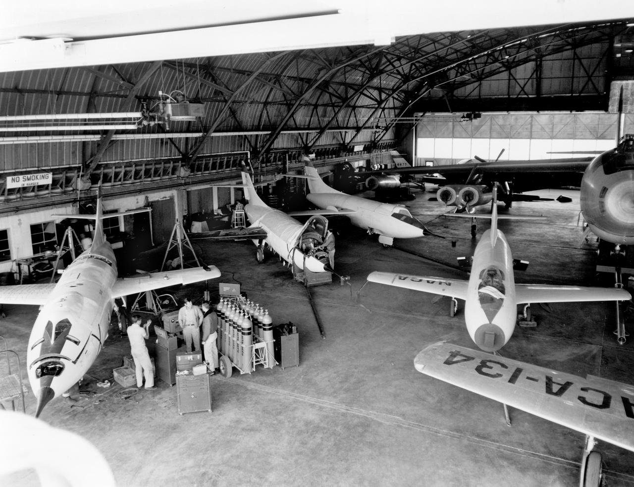
The aircraft in this 1953 photo of the National Advisory Committee for Aeronautics (NACA) hangar at South Base of Edwards Air Force Base showed the wide range of research activities being undertaken. On the left side of the hangar are the three D-558-2 research aircraft. These were designed to test swept wings at supersonic speeds approaching Mach 2. The front D-558-2 is the third built (NACA 145/Navy 37975). It has been modified with a leading-edge chord extension. This was one of a number of wing modifications, using different configurations of slats and/or wing fences, to ease the airplane's tendency to pitch-up. NACA 145 had both a jet and a rocket engine. The middle aircraft is NACA 144 (Navy 37974), the second built. It was all-rocket powered, and Scott Crossfield made the first Mach 2 flight in this aircraft on November 20, 1953. The aircraft in the back is D-558-2 number 1. NACA 143 (Navy 37973) was also carried both a jet and a rocket engine in 1953. It had been used for the Douglas contractor flights, then was turned over to the NACA. The aircraft was not converted to all-rocket power until June 1954. It made only a single NACA flight before NACA's D-558-2 program ended in 1956. Beside the three D-558-2s is the third D-558-1. Unlike the supersonic D-558-2s, it was designed for flight research at transonic speeds, up to Mach 1. The D-558-1 was jet-powered, and took off from the ground. The D-558-1's handling was poor as it approached Mach 1. Given the designation NACA 142 (Navy 37972), it made a total of 78 research flights, with the last in June 1953. In the back of the hangar is the X-4 (Air Force 46-677). This was a Northrop-built research aircraft which tested a swept wing design without horizontal stabilizers. The aircraft proved unstable in flight at speeds above Mach 0.88. The aircraft showed combined pitching, rolling, and yawing motions, and the design was considered unsuitable. The aircraft, the second X-4 built, was then used as a pilot traine
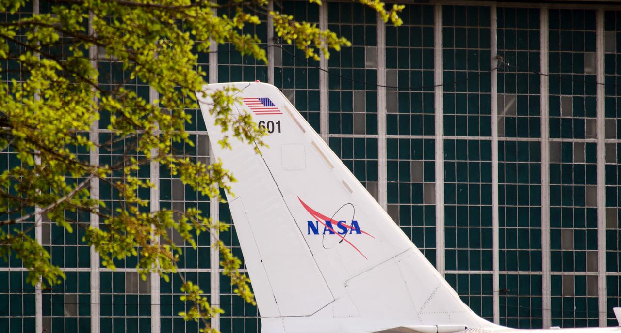
The Lockheed Viking S-3B aircraft was parked for re-fulling out near the hangar at Glenn Research Center in preparation for its departure and retirement from service. This former NAVY aircraft was the last such aircraft still flying. It has gone to a museum on the west coast. After leaving service with the NAVY, it came to GRC to be used in aircraft icing experiments. Tree branches frame the tail of this old war bird in front of the glass windows of the hangar door.
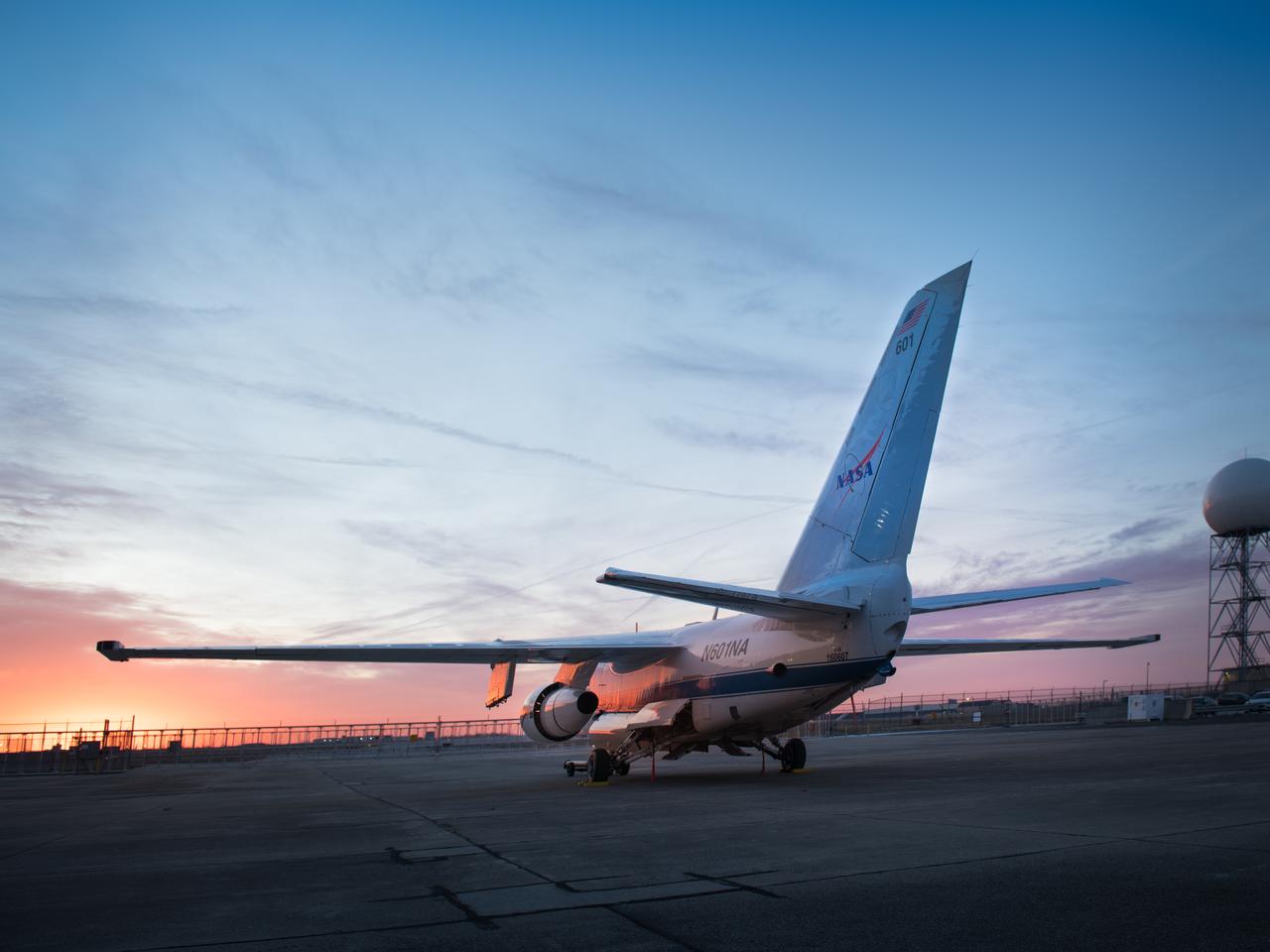
Glenn Research Center, Lockheed S-3 Viking Research Aircraft, N601NA at Sunrise
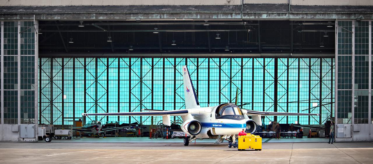
The Lockheed Viking S-3B aircraft is being pulled out of the hangar at Glenn Research Center in preparation for its departure and retirement from service. This former NAVY aircraft was the last such aircraft still flying. It has gone to a museum on the west coast. After leaving service with the NAVY, it came to GRC to be used in aircraft icing experiments. The swept wings made it suitable for such research as opposed to the straight wings on GRG’s other icing research aircraft, the De Havilland Twin Otter.
DC-9 PERFORMING MICROGRAVITY PARABALA -9/23/94
A truck with a specialized transporter drives out of the cargo hold of an Air Force C-5 Galaxy transport plane at the Shuttle Landing Facility at NASA's Kennedy Space Center in Florida to deliver the GOES-R spacecraft for launch processing. The GOES series are weather satellites operated by NOAA to enhance forecasts. The spacecraft is to launch aboard a United Launch Alliance Atlas V rocket in November.
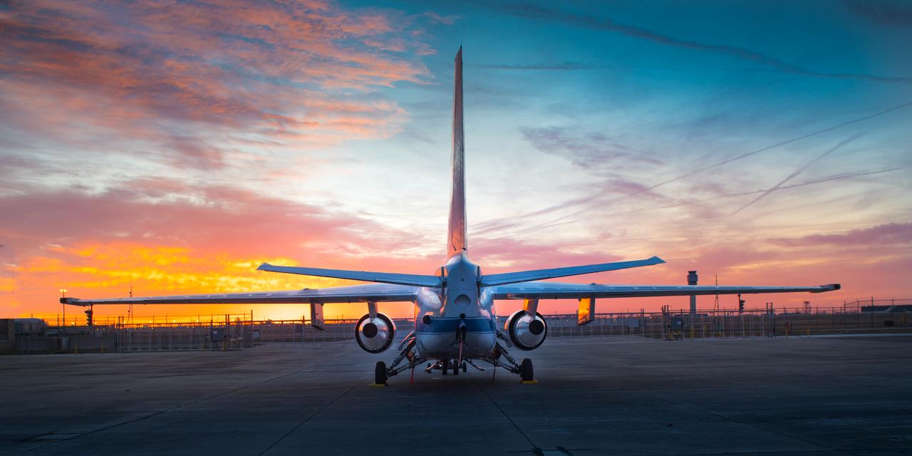
Lockheed S-3B Viking, N601NA at Sunrise on the Glenn Research Center Hangar Apron
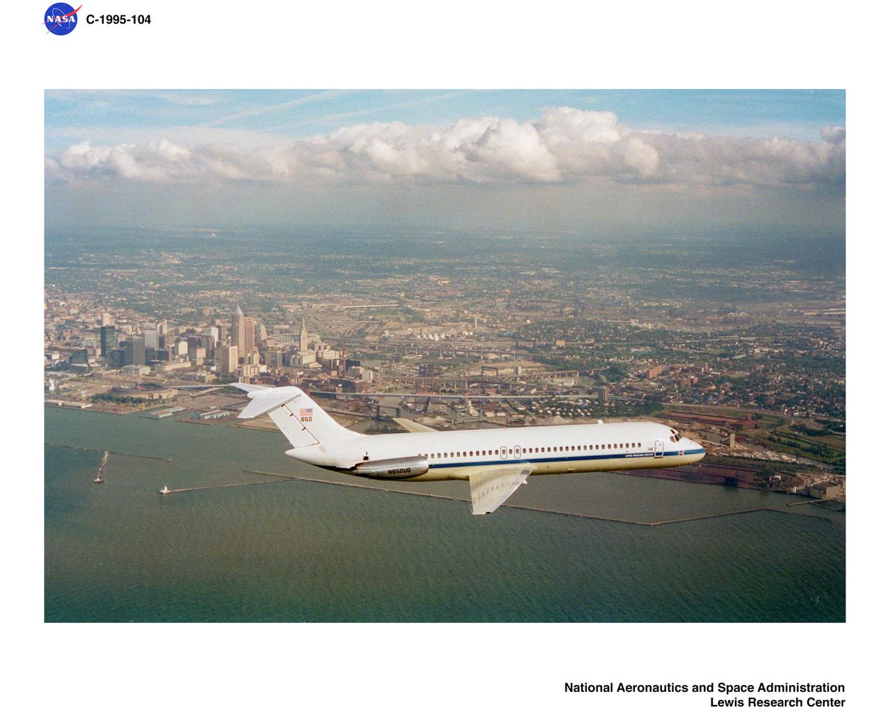
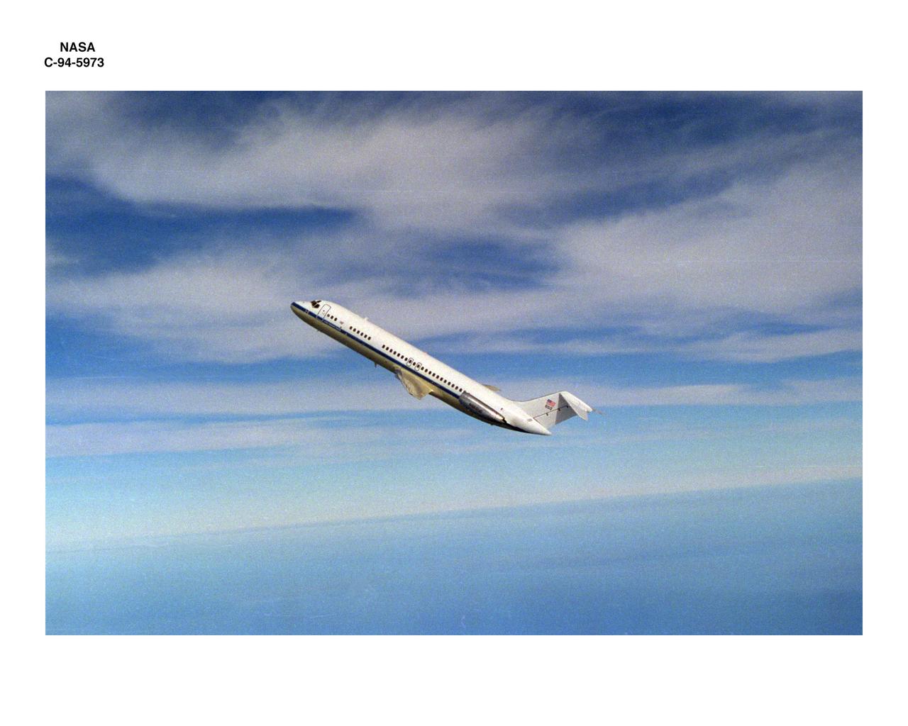
DC-9 AIRPLANE FLYING OVER CLEVELAND OHIO SEPTEMBER 23 1994
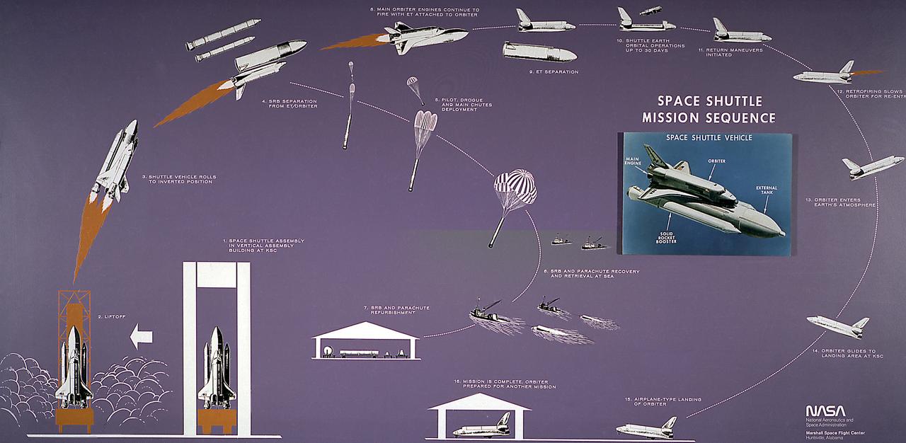
This diagram illustrates the Space Shuttle mission sequence. The Space Shuttle was approved as a national program in 1972 and developed through the 1970s. Part spacecraft and part aircraft, the Space Shuttle orbiter, the brain and the heart of the Space Transportation System (STS), required several technological advances, including thousands of insulating tiles able to stand the heat of reentry over the course of many missions, as well as sophisticated engines that could be used again and again without being thrown away. The airplane-like orbiter has three main engines, that burn liquid hydrogen and oxygen stored in the large external tank, the single largest structure in the Shuttle. Attached to the tank are two solid rocket boosters that provide the vehecile with most of the thrust needed for liftoff. Two minutes into the flight, the spent solids drop into the ocean to be recovered and refurbished for reuse, while the orbiter engines continue burning until approximately 8 minutes into the flight. After the mission is completed, the orbiter lands on a runway like an airplane.
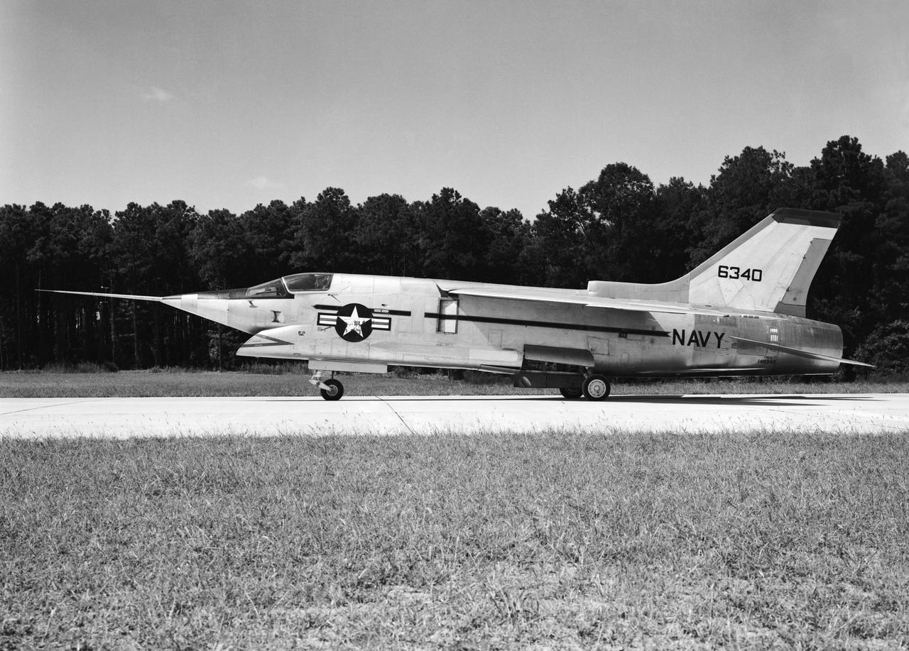
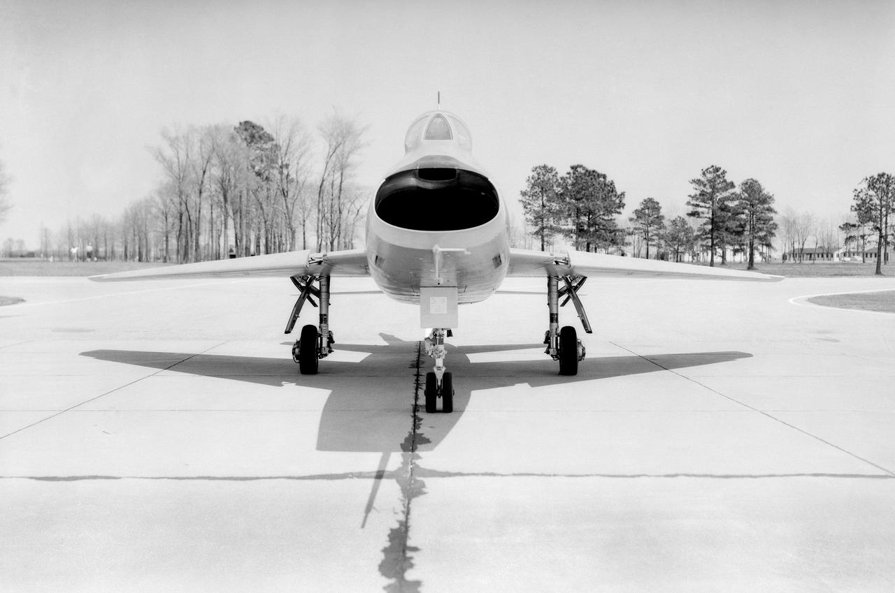
Crusader on runway. Navy aircraft number 6340. L59-6101 caption: The Navy's Vought XF8U-3 Supersonic Fighter was an entirely new design as compared to the earlier F8U Crusader series. This jet plane lost in competition with the McDonnell F4H, however, and was never put into production. Langley used the XF8U-3 in some of the first flight measurements of sonic boom intensity. Photograph published in Engineer in Charge A History of the Langley Aeronautical Laboratory, 1917-1958 by James R. Hansen. Page 507. Caption: Chance Vought F8U-3 airplane used in sonic boom investigation at Wallops, June-August 1959. Photograph published in A New Dimension Wallops Island Flight Test Range: The First Fifteen Years by Joseph Shortal. A NASA publication. Page 672.
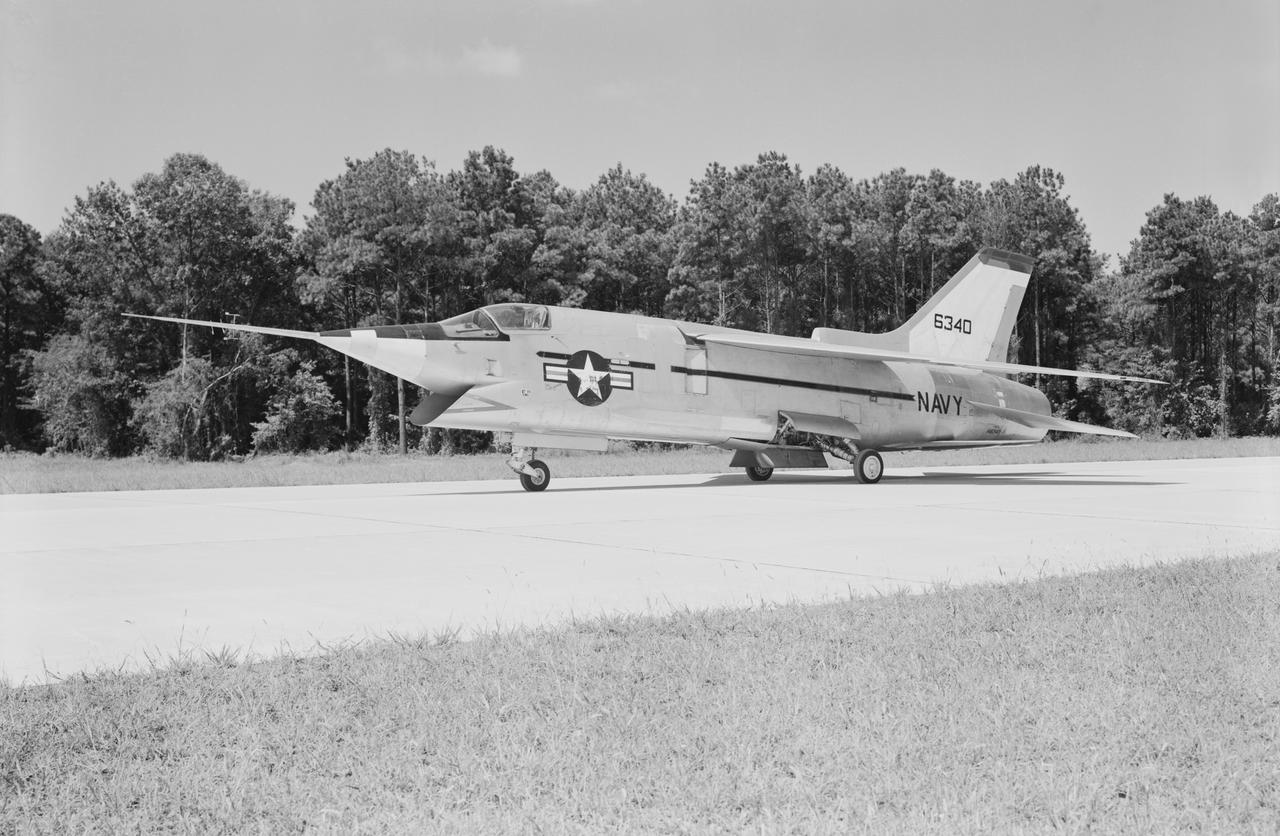
Crusader on runway. Navy aircraft number 6340. L59-6101 caption: The Navy's Vought XF8U-3 Supersonic Fighter was an entirely new design as compared to the earlier F8U Crusader series. This jet plane lost in competition with the McDonnell F4H, however, and was never put into production. Langley used the XF8U-3 in some of the first flight measurements of sonic boom intensity. Photograph published in Engineer in Charge A History of the Langley Aeronautical Laboratory, 1917-1958 by James R. Hansen. Page 507. Caption: Chance Vought F8U-3 airplane used in sonic boom investigation at Wallops, June-August 1959. Photograph published in A New Dimension Wallops Island Flight Test Range: The First Fifteen Years by Joseph Shortal. A NASA publication. Page 672.

The mural was created to celebrate the achievements of Wilbur and Orville Wright and to commemorate a century of powered flight. Central to the composition is the 1903 Wright Flyer. "On Dec. 17, 1903, the Wright brothers inaugurated the aerial age with their successful first flights of a heavier-than-air flying machine at Kitty Hawk, N.C. This airplane, known as the Wright Flyer, sometimes referred to as the Kitty Hawk Flyer, was the product of a sophisticated four-year program of research and development conducted by Wilbur and Orville Wright beginning in 1899. During the Wrights' design and construction of their experimental aircraft, they also pioneered many of the basic tenets and techniques of modern aeronautical engineering, such as the use of a wind tunnel and flight testing as design tools. Their seminal accomplishment encompassed not only the breakthrough first flight of an airplane, but also the equally important achievement of establishing the foundation of aeronautical engineering." Dr. Peter Jakab, Curator of Aviation, National Air and Space Museum, Smithsonian Institution "Celebrating One Hundred Years of Powered Flight, 1903-2003", documents many significant achievements in aeronautics and space flight from the dawn of powered flight to the present. Historic aircraft and spacecraft serve as the backdrop, highlighting six figures representing the human element that made these milestones possible. These figures stand, symbolically supported by the words of Wilbur Wright, "It is my belief that flight is possible…" The quote was taken from a letter written to his father on September 3rd, 1900, announcing Wilbur's intention to make "some experiments with a flying machine" at Kitty Hawk, North Carolina. "This year, Bob is helping us commemorate the Centennial of Flight with a beautiful mural slated for placement in our Dryden Flight Research Center that documents the history of flight from the Wright Flyer to the International Space Station. We should
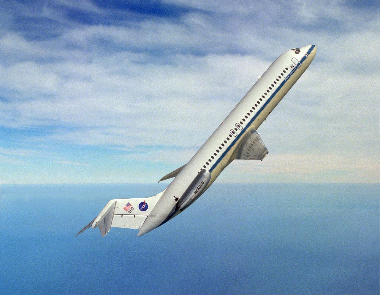
DC-9 AIRPLANE IN FLIGHT AT 50 DEGREES ANGLE OVER HORIZON
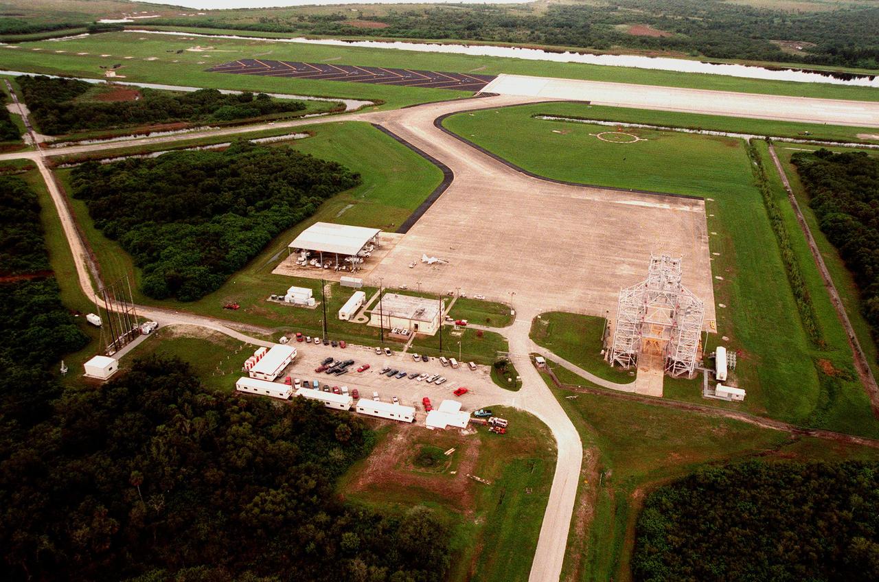
From the air over KSC can be seen the Shuttle Landing Facility. Orbiter landings at the Kennedy Space Center are made on one of the largest runways in the world. The runway is located 3.2 km (2 miles) northwest of the Vehicle Assembly Building and is 4,572 meters (15,000ft) long and 91.4 meters (300ft) wide -- about as wide as the length of a football field. It has 305 meters (1000ft) of paved overruns at each end and the paving thickness is 40.6cm (15 inches) at the center. At left in the photo is the Aircraft Ground Equipment Shed; in the center is the Landing Aids Control Building (LACB) which supports landing operations and houses operations personnel. Located at the northeast corner of the parking apron is the Mate/Demate device (MDD) used to raise and lower the orbiter from its 747 carrier aircraft during ferry operations. The open-truss steel structure is equipped with hoists, adapters and movable platforms for access to certain orbiter components and equipment. It also is equipped with lightning protection devices. The MDD is 45.7 meters (150ft) long, 28.3 meters (93ft) wide and 32 meters (105ft) high. On the landing area in front of the SLF is a T-38 jet airplane.
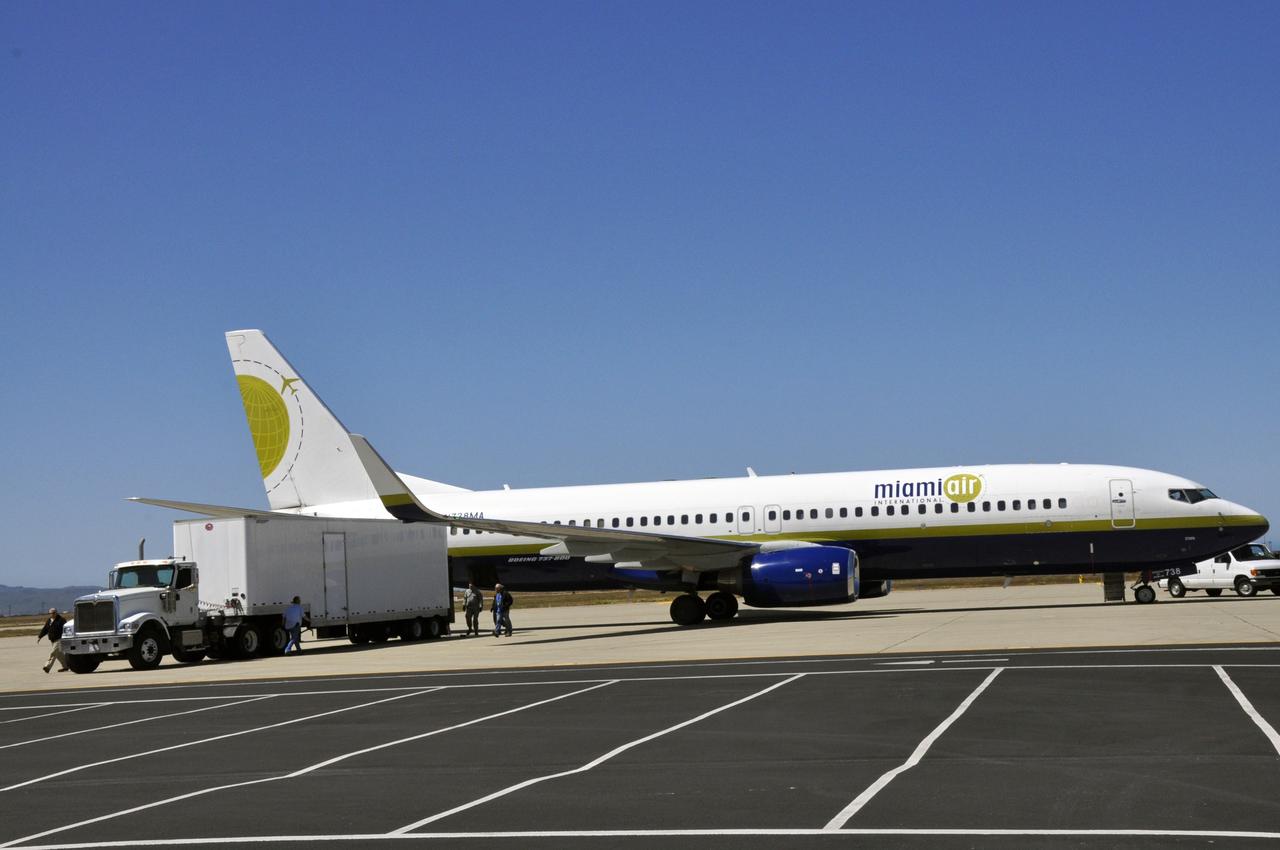
VANDENBERG AIR FORCE BASE, Calif. – Supplies are loaded onto the Miami Air International Boeing 737 airplane that will accompany Orbital Sciences’ L-1011 carrier aircraft from Vandenberg Air Force Base in California to the U.S. Army's Ronald Reagan Ballistic Missile Defense Test Site on Kwajalein Atoll, part of the Marshall Islands in the Pacific Ocean. Forty-nine passengers, including the launch team, are traveling to Kwajalein aboard the charter flight. The launch team is made up of employees of NASA, Orbital Sciences and a.i. solutions. The Pegasus, mated to its NuSTAR payload, will be launched from the carrier aircraft 117 nautical miles south of Kwajalein at latitude 6.75 degrees north of the equator. The high-energy X-ray telescope will conduct a census of black holes, map radioactive material in young supernovae remnants, and study the origins of cosmic rays and the extreme physics around collapsed stars. Launch is scheduled for June 13. For more information, visit http://www.nasa.gov/nustar. Photo credit: NASA/Randy Beaudoin, VAFB
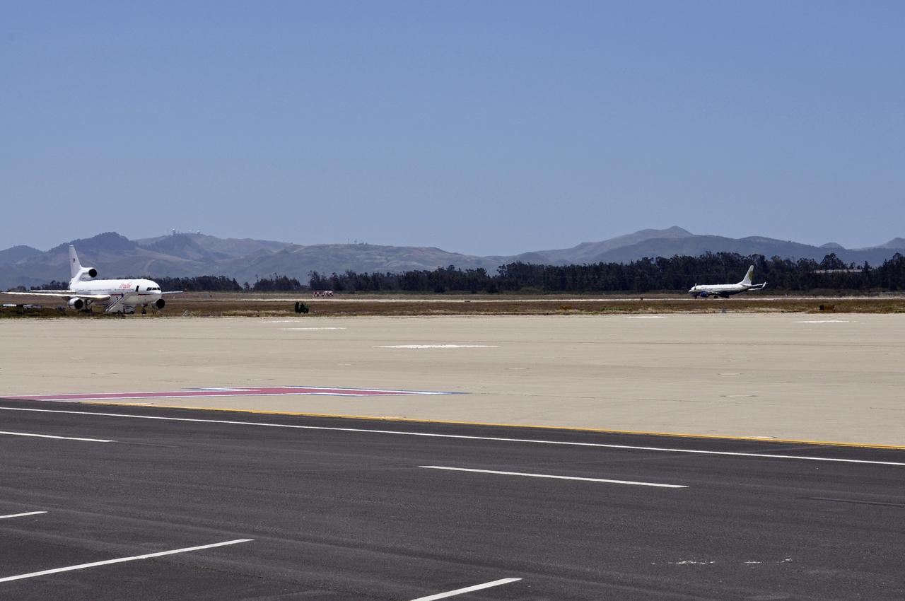
VANDENBERG AIR FORCE BASE, Calif. – The Miami Air International Boeing 737 airplane, at right, accompanying Orbital Sciences’ L-1011 carrier aircraft, prepares for takeoff from Vandenberg Air Force Base in California for the U.S. Army's Ronald Reagan Ballistic Missile Defense Test Site on Kwajalein Atoll, part of the Marshall Islands in the Pacific Ocean. Forty-nine passengers, including the launch team, are traveling to Kwajalein aboard the charter flight. The launch team is made up of employees of NASA, Orbital Sciences and a.i. solutions. Orbital’s L-1011, at left, transporting their Pegasus rocket and NASA’s Nuclear Spectroscopic Telescope Array, or NuSTAR, will follow close behind. The Pegasus, mated to its NuSTAR payload, will be launched from the carrier aircraft 117 nautical miles south of Kwajalein at latitude 6.75 degrees north of the equator. The high-energy X-ray telescope will conduct a census of black holes, map radioactive material in young supernovae remnants, and study the origins of cosmic rays and the extreme physics around collapsed stars. Launch is scheduled for June 13. For more information, visit http://www.nasa.gov/nustar. Photo credit: NASA/Randy Beaudoin, VAFB
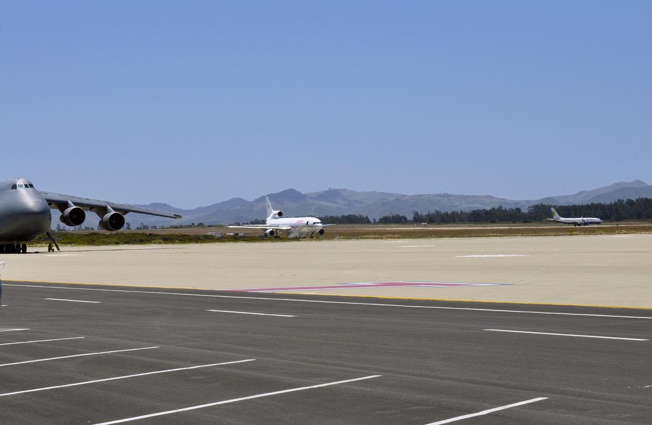
VANDENBERG AIR FORCE BASE, Calif. – The Miami Air International Boeing 737 airplane, at right, accompanying Orbital Sciences’ L-1011 carrier aircraft, takes off from Vandenberg Air Force Base in California for the U.S. Army's Ronald Reagan Ballistic Missile Defense Test Site on Kwajalein Atoll, part of the Marshall Islands in the Pacific Ocean. Forty-nine passengers, including the launch team, are traveling to Kwajalein aboard the charter flight. The launch team is made up of employees of NASA, Orbital Sciences and a.i. solutions. Orbital’s L-1011, at left, transporting their Pegasus rocket and NASA’s Nuclear Spectroscopic Telescope Array, or NuSTAR, will follow close behind. The Pegasus, mated to its NuSTAR payload, will be launched from the carrier aircraft 117 nautical miles south of Kwajalein at latitude 6.75 degrees north of the equator. The high-energy X-ray telescope will conduct a census of black holes, map radioactive material in young supernovae remnants, and study the origins of cosmic rays and the extreme physics around collapsed stars. Launch is scheduled for June 13. For more information, visit http://www.nasa.gov/nustar. Photo credit: NASA/Randy Beaudoin, VAFB
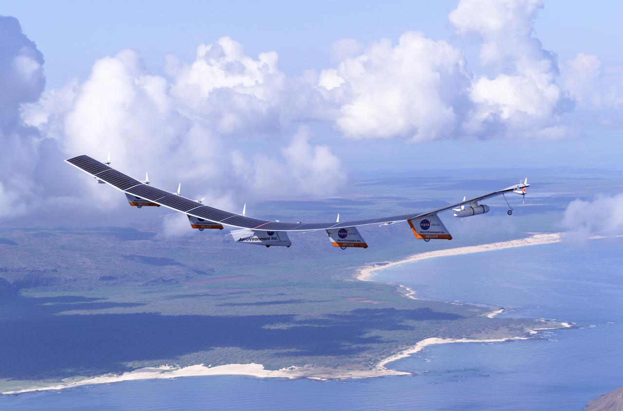
The first flight of a large aircraft to be powered by electric fuel cells began with a takeoff at 8:43 a.m. HST today from the Hawaiian island of Kauai. The Helios Prototype flying wing, built by AeroVironment, Inc., of Monrovia, Calif., as part of NASA's Environmental Research Aircraft and Sensor Technology (ERAST) program, used solar panels to power its 10 electric motors for takeoff and during daylight portions of its planned 20-hour shakedown flight. As sunlight diminishes, Helios will switch to a fuel cell system to continue flight into the night. The takeoff set the stage for a two-day Helios endurance flight in the stratosphere planned for mid-July. The Helios wing, spanning 247 feet and weighing about 2,400 pounds, is giving NASA and industry engineers confidence that remotely piloted aircraft will be able to stay aloft for weeks at a time, providing environmental monitoring capabilities and telecommunications relay services. Helios is an all-electric airplane. In addition to being non-polluting, Helios can fly above storms, and use the power of the sun to stay aloft during daylight. Key to the success of this type of aircraft is the ability to fly in darkness, using fuel cells when sunlight cannot furnish energy. Helios flew over the Navy's Pacific Missile Range Facility where favorable sun exposure and test ranges closed to other air traffic benefited the NASA research effort. In 2003 the aircraft was lost to a crash.
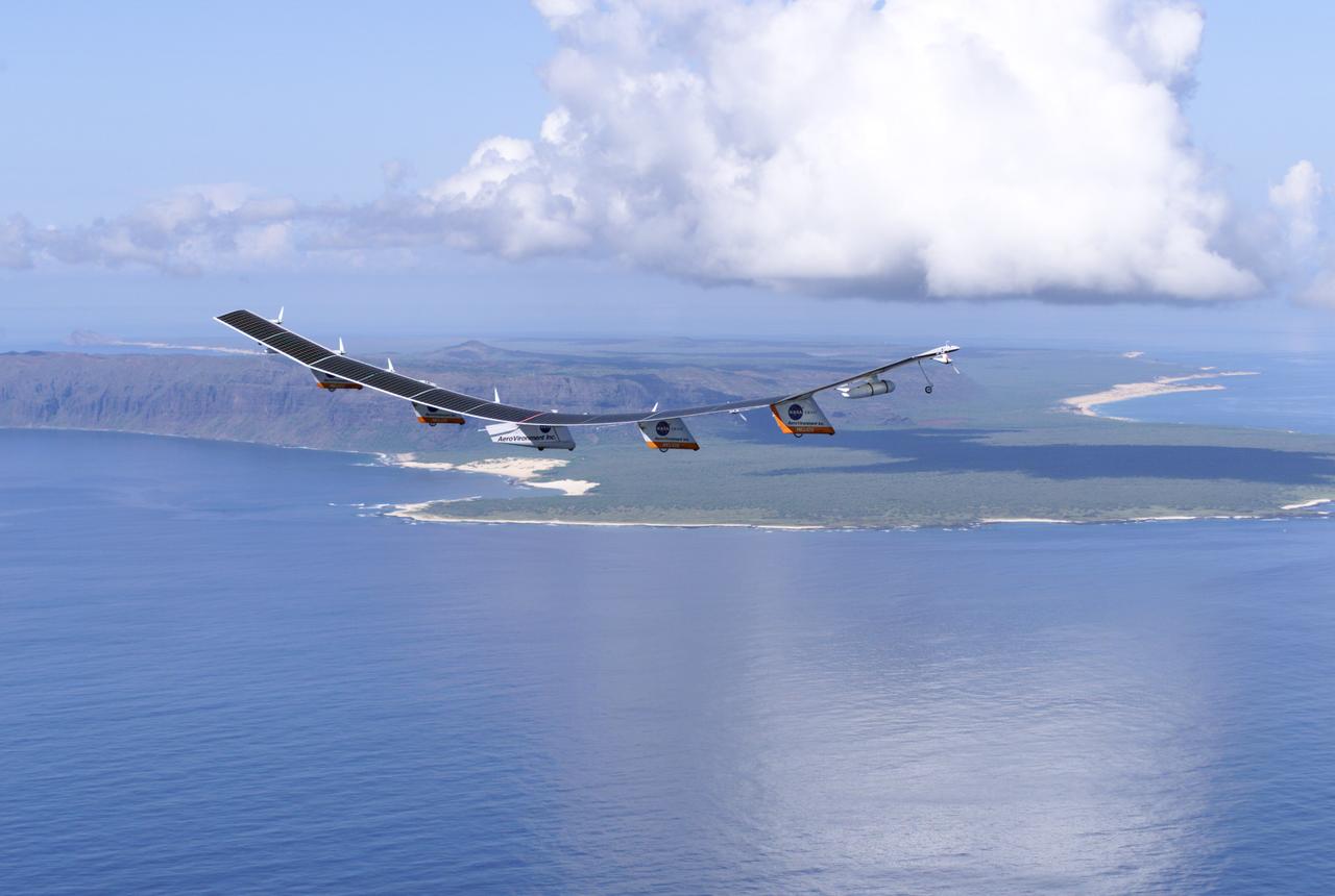
The first flight of a large aircraft to be powered by electric fuel cells began with a takeoff at 8:43 a.m. HST today from the Hawaiian island of Kauai. The Helios Prototype flying wing, built by AeroVironment, Inc., of Monrovia, Calif., as part of NASA's Environmental Research Aircraft and Sensor Technology (ERAST) program, used solar panels to power its 10 electric motors for takeoff and during daylight portions of its planned 20-hour shakedown flight. As sunlight diminishes, Helios will switch to a fuel cell system to continue flight into the night. The takeoff set the stage for a two-day Helios endurance flight in the stratosphere planned for mid-July. The Helios wing, spanning 247 feet and weighing about 2,400 pounds, is giving NASA and industry engineers confidence that remotely piloted aircraft will be able to stay aloft for weeks at a time, providing environmental monitoring capabilities and telecommunications relay services. Helios is an all-electric airplane. In addition to being non-polluting, Helios can fly above storms, and use the power of the sun to stay aloft during daylight. Key to the success of this type of aircraft is the ability to fly in darkness, using fuel cells when sunlight cannot furnish energy. Helios flew over the Navy's Pacific Missile Range Facility where favorable sun exposure and test ranges closed to other air traffic benefited the NASA research effort. In 2003 the aircraft was lost to a crash.
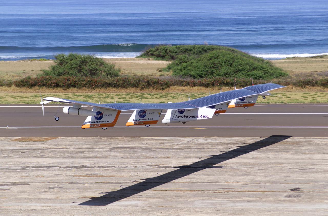
The first flight of a large aircraft to be powered by electric fuel cells began with a takeoff at 8:43 a.m. HST today from the Hawaiian island of Kauai. The Helios Prototype flying wing, built by AeroVironment, Inc., of Monrovia, Calif., as part of NASA's Environmental Research Aircraft and Sensor Technology (ERAST) program, used solar panels to power its 10 electric motors for takeoff and during daylight portions of its planned 20-hour shakedown flight. As sunlight diminishes, Helios will switch to a fuel cell system to continue flight into the night. The takeoff set the stage for a two-day Helios endurance flight in the stratosphere planned for mid-July. The Helios wing, spanning 247 feet and weighing about 2,400 pounds, gave NASA and industry engineers confidence that remotely piloted aircraft would be able to stay aloft for weeks at a time, providing environmental monitoring capabilities and telecommunications relay services. Helios was an all-electric airplane. In addition to being non-polluting, Helios flew above storms, and used the power of the sun to stay aloft during daylight. Key to the success of this type of aircraft was the ability to fly in darkness, using fuel cells when sunlight cannot furnish energy. Helios flew over the Navy's Pacific Missile Range Facility where favorable sun exposure and test ranges closed to other air traffic benefited the NASA research effort. In 2003 the aircraft was lost to a crash.
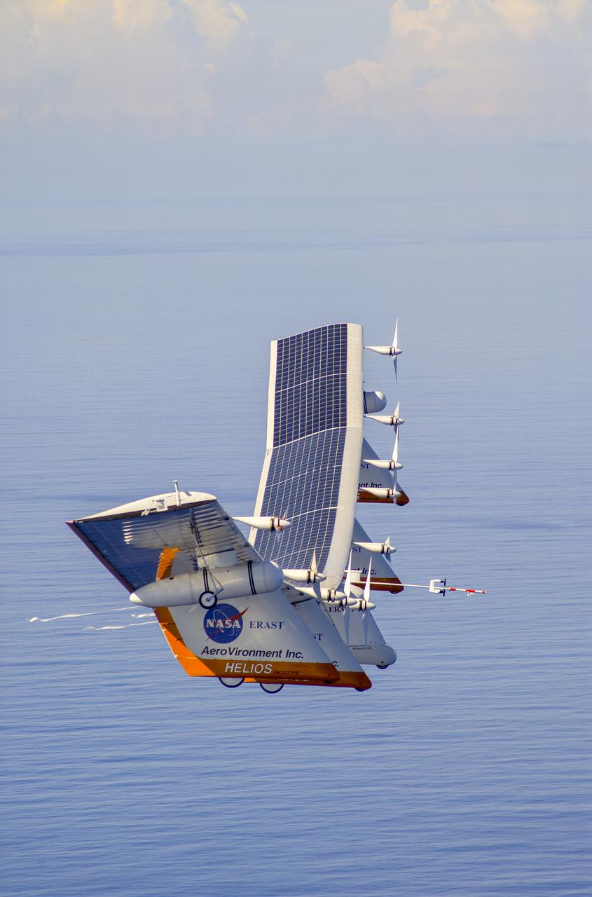
The first flight of a large aircraft to be powered by electric fuel cells began with a takeoff at 8:43 a.m. HST today from the Hawaiian island of Kauai. The Helios Prototype flying wing, built by AeroVironment, Inc., of Monrovia, Calif., as part of NASA's Environmental Research Aircraft and Sensor Technology (ERAST) program, used solar panels to power its 10 electric motors for takeoff and during daylight portions of its planned 20-hour shakedown flight. As sunlight diminishes, Helios will switch to a fuel cell system to continue flight into the night. The takeoff set the stage for a two-day Helios endurance flight in the stratosphere planned for mid-July. The Helios wing, spanning 247 feet and weighing about 2,400 pounds, is giving NASA and industry engineers confidence that remotely piloted aircraft will be able to stay aloft for weeks at a time, providing environmental monitoring capabilities and telecommunications relay services. Helios is an all-electric airplane. In addition to being non-polluting, Helios can fly above storms, and use the power of the sun to stay aloft during daylight. Key to the success of this type of aircraft is the ability to fly in darkness, using fuel cells when sunlight cannot furnish energy. Helios flew over the Navy's Pacific Missile Range Facility where favorable sun exposure and test ranges closed to other air traffic benefited the NASA research effort. In 2003 the aircraft was lost to a crash.
The first flight of a large aircraft to be powered by electric fuel cells began with a takeoff at 8:43 a.m. HST today from the Hawaiian island of Kauai. The Helios Prototype flying wing, built by AeroVironment, Inc., of Monrovia, Calif., as part of NASA's Environmental Research Aircraft and Sensor Technology (ERAST) program, used solar panels to power its 10 electric motors for takeoff and during daylight portions of its planned 20-hour shakedown flight. As sunlight diminishes, Helios will switch to a fuel cell system to continue flight into the night. The takeoff set the stage for a two-day Helios endurance flight in the stratosphere planned for mid-July. The Helios wing, spanning 247 feet and weighing about 2,400 pounds, is giving NASA and industry engineers confidence that remotely piloted aircraft will be able to stay aloft for weeks at a time, providing environmental monitoring capabilities and telecommunications relay services. Helios is an all-electric airplane. In addition to being non-polluting, Helios can fly above storms, and use the power of the sun to stay aloft during daylight. Key to the success of this type of aircraft is the ability to fly in darkness, using fuel cells when sunlight cannot furnish energy. Helios flew over the Navy's Pacific Missile Range Facility where favorable sun exposure and test ranges closed to other air traffic benefited the NASA research effort. In 2003 the aircraft was lost to a crash.
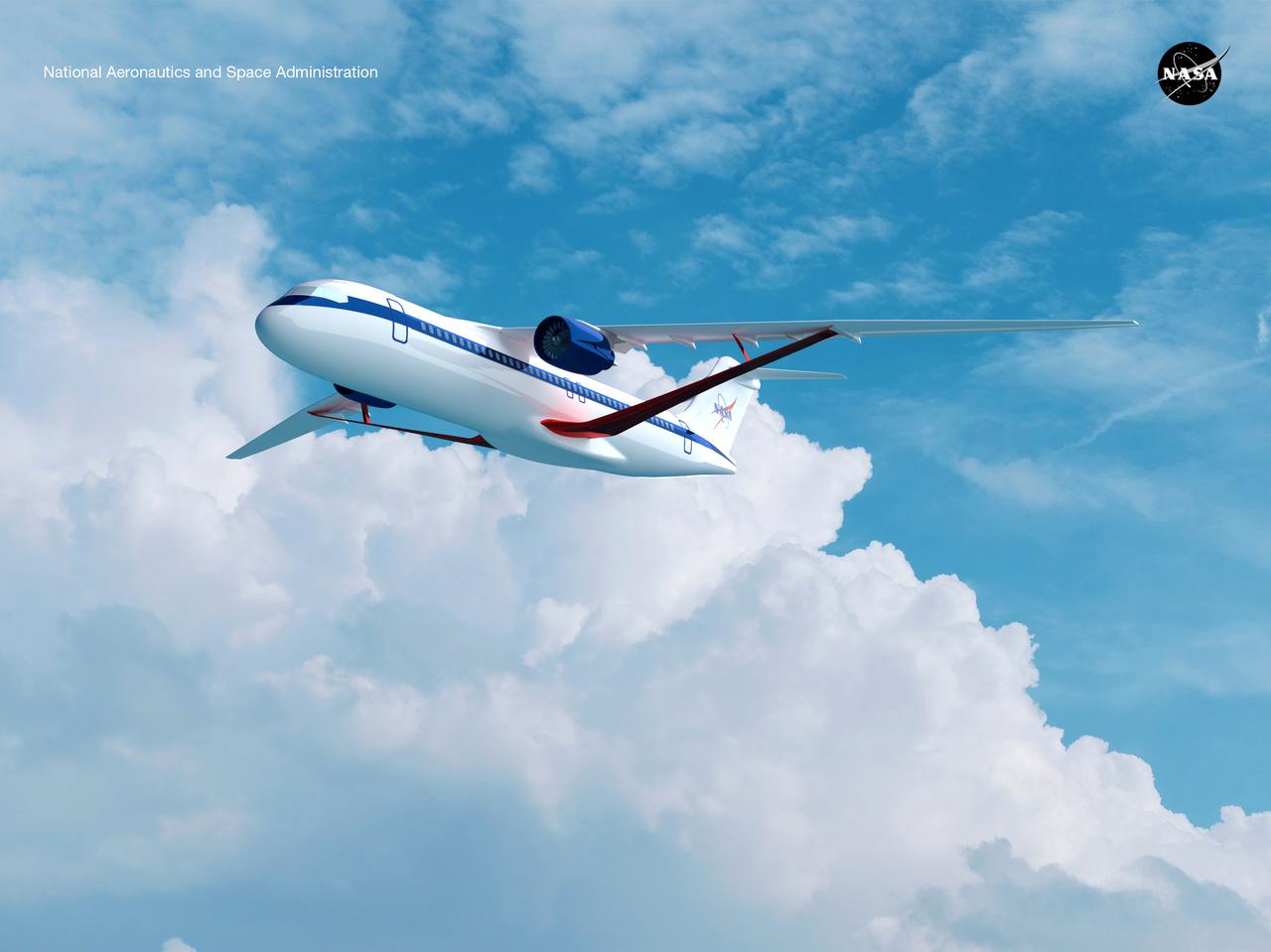
Notice anything different about the wings on this airliner? This conceptual truss-braced wing narrowbody is an aircraft with a 170ft span folding wing. By utilizing trusses, the aircraft can have longer, thinner wings with greater aspect ratios. This, in turn, translates into less drag and 5-10% less fuel burned. The Transonic Truss-Braced Wing aircraft originated from a joint effort by NASA and Boeing to develop subsonic commercial transport concepts – meeting NASA-defined metrics in terms of reduced noise, emissions, and fuel consumption. The design is currently undergoing wind tunnel testing and other studies by NASA researchers.
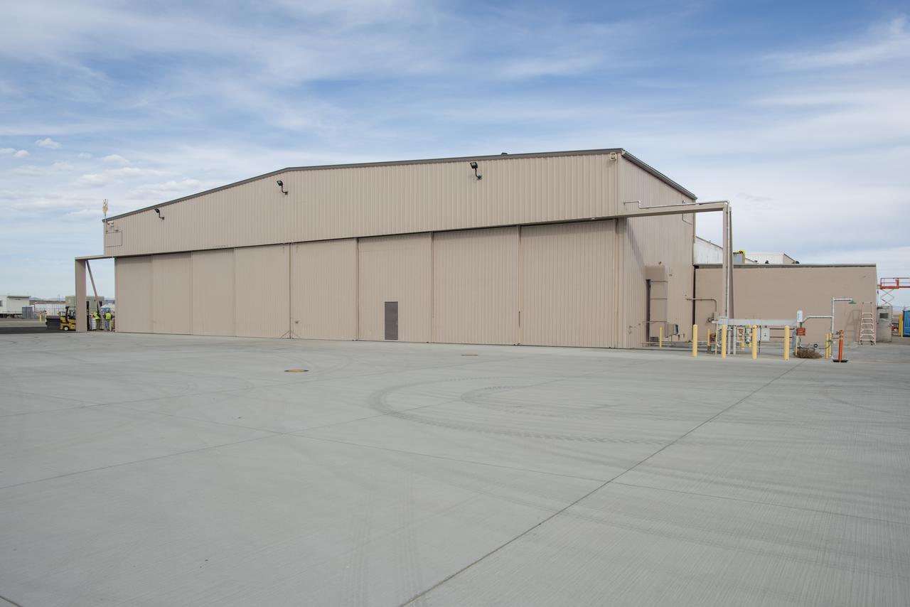
This is how Building 4826, the future home of the X-59 Quiet SuperSonic Technology aircraft, at NASA's Armstrong Flight Research Center in Edwards, California, looks as the building's renovations continue.
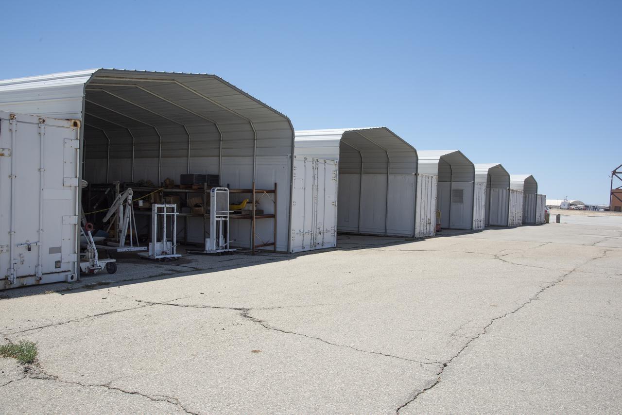
This 8,800-square-foot canopy area was demolished during the refurbishment of the east side of Building 4826, the future home of the X-59 Quiet SuperSonic Technology aircraft, at NASA's Armstrong Flight Research Center in Edwards, California.